owner's manual - c.searspartsdirect.com · parts list ... if this craftsman snow thrower is...
TRANSCRIPT

Owner's Manual
5.0 Horse Power
24" Two-Stage Wheel DriveSnow Thrower
Model No.
247.886640
CAUTION: Before
using this product,read this manual and
follow all safety rulesand operatinginstructions.
• Safety• Assembly• Operation• Service• Maintenance
• EspaSol
Sears, Roebuck And Co., Hoffman Estates, IL 60179, U.S.A.Visit our website: www.sears.com/craffsman
PRINTED IN U.S.A. FORM NO.770-10433
(8/2ooo)

Content Page
Warranty Information ......................................... 2
Safe Operation Practices ................................... 3
Hardware Pack .................................................. 5
Assembly ........................................................... 6
Operation ........................................................... 10
Maintenance ...................................................... t 3
Content Page
Service & Adjustment......................................... 15
Off-Season Storage ........................................... 19
Trouble-Shooting ............................................... 20
Parts List ............................................................ 21
Espanol .............................................................. 34
Two -Year Warranty on Craftsman Snow ThrowerFor two years from the date of purchase, when this Craftsman Snow Thrower is maintained, lubricated and tunedup according to the instructions in the owner's manual, Sears will repair, free of charge, any defect in materialand workmanship.
If this Craftsman snow thrower is used for commercial or rental purposes, this warranty applies for only 30 daysfrom the date of purchase.
Thls warranty does not cover:
Expendable items which become worn during normal use, such as skid shoes, shave plate and sparkplugs.
Repairs necessary because of operator abuse or negligence, including bent crankshafts and the failure tomaintain the equipment according to the instructions contained in the owner's manual
WARRANTY SERVICE IS AVAILABLE BY RETURNING THE CRAFTSMAN SNOW THROWER TO THE NEARESTSEARS SERVICE CENTER/DEPARTMENT IN THE UNITED STATES.
Thls warranty applies only while this product Is In use In the United States.
This warranty gives you specific legalrights and you may also have other dghts which may vary from state to state.
SEARS, ROEBUCK AND CO., D/817WA, HOFFMAN ESTATES, IL 60179
Horsepower: ......................... 5.0
Engine Oil ............................. SAE 5W30 oil
Spark Plug: ........................... RJ-19LM
Engine: .................................. 143.015007
Model Number 247.886640Serial Number ...........................................................Date of Purchase ......................................................Record both serial number and date of purchase andkeep in a safe place for future reference.
2
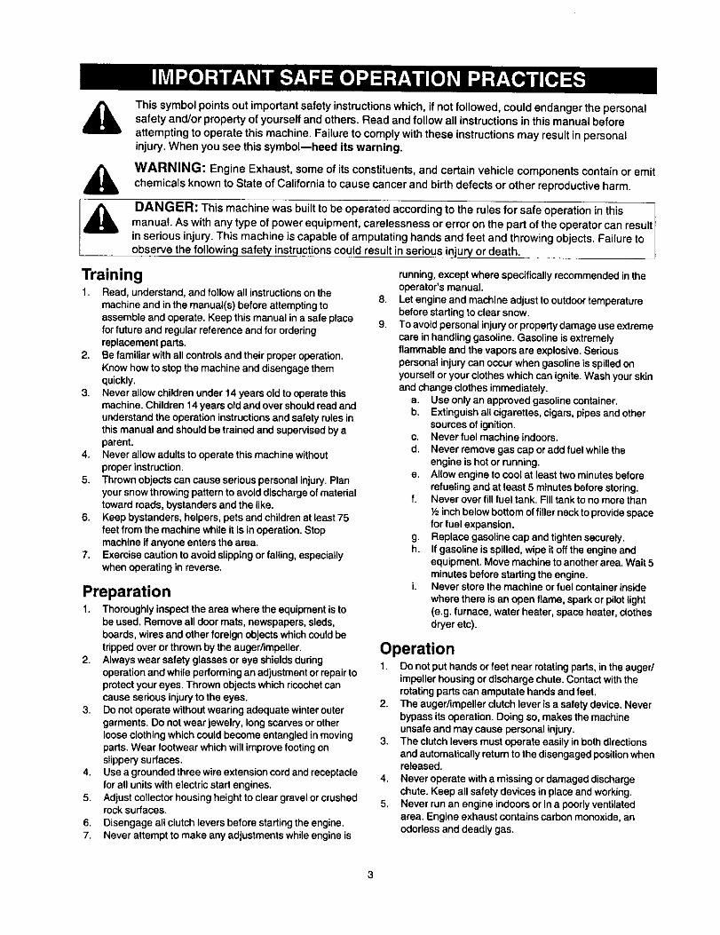
This symbolpoints out important safety instructionswhich, if not followed, could endanger the personalsafety and/or property of yourself and others. Read and follow all instructions in this manual beforeattempting to operate this machine. Failure to comply with these instructions may result in personalinjury. When you see this symbol--heed its warning.
A WARNING: Engine Exhaust, some of itsconstituents, and certain vehicle components containor emitchemicals known to State of Californiato cause cancer and birth defects or other reproductiveharm.
DANGER: This machine was built to be operated according to the rules for safe operation in this Imanual. As withany type of power equipment, carelessness or erroron the part of the operator can resultI
in seriousinjury.This machine is capable of amputating hands and feet and throwingobjects. Failure toobserve the following safety instructionscould resultin serious injuryor death.
Training1. Read, understand, and follow all instructionson the
machine and in the manual(s) before attempting toassemble and operate. Keep this manual in a safe placefor future and regular reference and for orderingreplacement parts.
2. Be familiar with all controls and their proper operation.Know how to stop the machine and disengage themquickly.
3. Never allow children under 14 years oldto operate thismachine. Children 14 years old and over shouldread andunderstand the operation instructions and safety rules inthis manual and should be trained and supervised by aparent.
4. Never allow adults to operate this machine withoutproper instruction.
5. Thrown objects can cause serious personal injury. Planyour snow throwing pattern to avoid discharge of materialtoward roads, bystanders and the like.
6. Keep bystanders, helpers, pets and children at least 75feet from the machine while it is inoperation. Stopmachine if anyone enters the area.
7. Exercise caution to avoid slippingor falling, especiallywhen operating in reverse.
Preparation1. Thoroughly inspect the area where the equipment is to
be used. Remove all door mats, newspapers, sleds,boards, wires and other foreign objectswhich could betrippedover or thrown by the auger/impeller.
2. Always wear safety glasses oreye shields duringoperation and while performing an adjustment or repairtoprotectyour eyes. Thrown objectswhich ricochetcancause serious injuryto the eyes.
3. Do not operate without wearing adequate winter outergarments. Do not wear jewelry, long scarves or otherloose clothingwhich coutd become entangled inmovingparts. Wear footwear which will improve footingonslippery surfaces.
4. Use a grounded three wireextension cord and receptaclefor all units with electricstart engines.
5. Adjust collector housingheight to clear gravel or crushedrock surfaces.
6. Disengage all clutch levers before starting the engine.7. Never attempt to make any adjustments while engine is
8.
9.
running, except where specifically recommended in theoperator's manual.Let engine and machine adjust to outdoortemperaturebefore stading to clear snow.To avoidpersonal injuryor propertydamage use extremecare in handling gasoline. Gasoline is extremelyflammable and the vapors are explosive. Seriouspersonal injurycan occur when gasoline is spilledonyourselfor your clothes which can ignite. Wash your skinand change clothes immediately.
a. Use only an approved gasoline container.b. Extinguishall cigarettes, cigars, pipes and other
sources of ignition.c. Neverfuel machine indoors.d. Never remove gas cap or add fuel while the
engine is hot or running.e. Allow engine to cool at least two minutes before
refueling and at least 5 minutes before storing.f. Never over fill fuel tank. Fill tank to no more than
1,6inch below bottom of filler neck to provide spacefor fuel expansion.
g. Replace gasoline cap and tighten securely.h. If gasoline is spilled, wipe it off the engine and
equipment. Move machine to another area. Wait 5minutes before starting the engine.
i. Never store the machine or fuel container insidewhere there is an open flame, spark or pilot light(e.g. furnace, water heater, space heater, clothesdryer etc).
Operation1. Do not put hands or feet near rotating parts, in the auger/
impeller housing or discharge chute. Contact with therotating parts can amputate hands and feet.
2. The auger/impeller clutch lever is a safety device, Neverbypass itsoperation. Doing so, makes the machineunsafe and may cause personal injury.
3. The clutch levers must operate easily in both directionsand automatically return to the disengaged position whenreleased.
4. Never operate with a missing or damaged dischargechute. Keep all safety devices in place and working.
5. Never run an engine indoors or in a poorly ventilatedarea. Engine exhaust contains carbon monoxide, anodorless and deadly gas.

6. Donot operate machine while under the influence ofalcoholor drugs.
7. Muffler and engine become hot and can cause a burn. Donottouch.
8. Exercise extreme caution when operating on orcrossinggravel surfaces. Stay alert for hidden hazards or traffic.
9. Exercise caution when changing direction and whileoperating on slopes.
tO. Plan your snow throwing pattern to avoid dischargetowards windows, walls, cars etc. To avoid propertydamage or personal injury caused by a ricochet.
t 1. Never direct discharge at children, bystanders and petsorallow anyone in frontof the machine.
12. Do not overload machine capacity by attempting to clearsnow at too fast of a rate.
13. Never operate thismachine without good visibilityorlight.Always be sure of your footing and keep a firmholdon the handles. Walk, never run.
14. Disengage power to the auger/impeller whentransportingor not in use.
15. Never operate machine at high transport speeds onslippery surfaces. Lookdown and behind and use carewhen in reverse.
16. If the machine shouldstart to vibrate abnormally,stop theengine, disconnect the spark plug and ground itagainstthe engine. Inspect thoroughly for damage. Repair anydamage before startingand operating.
17. Disengage all clutch levers and stop engine before youleave the operating position(behind the handles). Waituntil the auger/impeller comes to a complete stopbeforeuncloggingthe discharge chute, making anyadjustments, or inspections.
18. Never put your hand inthe discharge or collectoropenings. Always use a clearing tool to unclogthedischarge opening.
19. Use only attachments and accessories apprcved by themanufacturer (e.g. wheel weights, tire chains, cabs etc.).
20. If situabons occur which are not covered in thismanual,use care and goodjudgment. Contact your nearest Searsservice center for assistance.
Maintenance and Storage1. Never tamper with safety devices. Check their proper
operation regularly.2. Disengage all clutch leversand stopengine. Wait until
the auger/impeller come to a completestop. Disconnectthe spark plugwire and ground against the engine toprevent unintended startingbefore cleaning, repairing,orinspecting.
3. Check bolts, and screwsfor propertightness at frequentintervals to keep the machine insafe working condition,Also, visually inspect machine for any damage.
4. Do not change the engine governor settingor over-speedthe engine. The governor controlsthe maximum safeoperating speed of the engine.
5. Snow thrower shave plates and skidshoes are subject towear and damage. For your safety protection,frequentlycheck all components and replace withoriginalequipment manufacturer's (O.EM.) parts only. "Use ofparts which do not meet the originalequipmentspecifications may lead to improper performance andcompromise safety!"
6. Check clutch controls periodicallyto verify they engageand disengage properlyand adjust, if necessary. Refer tothe adjustment section in thisoperator's manual forinstructions.
7. Maintain or replace safety and instructionlabels, asnecessary.
8, Observe proper disposal laws and regulationsfor gas,oil, etc. to protectthe environment.
9. Prior to storing, runmachine a few minutes to clear snowfrom machine and prevent freeze up of auger/impeller.
tO. Never store the machine or fuel container inside where
there is an open flame, spark or pilot lightsuch asa waterheater, furnace ,clothesdryer etc.
11. Always refer to the operator's manual for praperinstructionson off-season storage.
Your Responsibility:Restnct the use of this power machine to persons who read,understand and follow the warnings and instructionsin thismanual and on the machine. The mostimportantsafety labelsare reproduced below. For a detailed labels map, seeParts List section.
1.BENPAWAYEROMROTATINGIMPeJ,.ERANDS. €_OT'_TEREHENPELL_ERACRERCANAMPUTATElaNDSAHDFEET.
E.DISENGAGECLUTCHLEVER|.STOPENGINE.ANDPJUIAIHIERIIiRHANOLEN6RILLALLMOERi6PARTSHAVEOTOPPEOBEFOREUNCLOG61i46ORSERVICINGMACHINE.
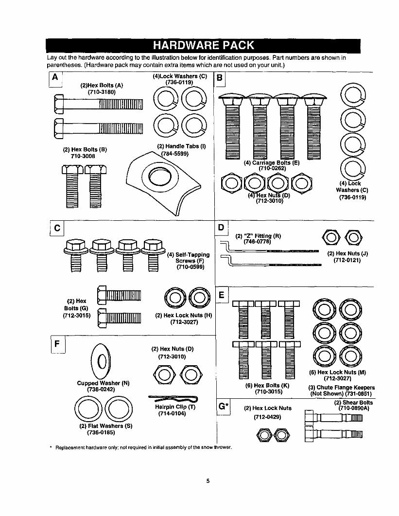
Lay outthe hardware according to the illustrationbelow for identificationpurposes. Part numbers are shown inparentheses. (Hardware pack may contain extra items which are not used on your unit.)
A!_ (2)Hex Bolts (A)
(710-3180)
1111111111111111111111
IIIIIIIIII11i1111111II
(2) Hex Bolts(B)710-3008
(4)Lock Washers (C) I:_(736-0119)
©©©©
12) Handle Tabs 11)
___ Screws (F)_ t_l _ FlO-O509)
(2)Hex @11t11111111111!111
Belle(G)_lllllllllllllllll](712-3015)
@Cupped Washer (N)
(736°0242)
Q©(2) Flat Washers IS)
(736-0185)
(2) Hex Nuts (D)
(712-3010)
©©Hairpin Clip IT)
(714-0104)
(4) Carriage Bolts (E)(710-0262)
G g,G
©
Washers (C)
(736-0119)
(7,,-'0'7%__")(2) Hex Nuts (J)
_. .............................. (712-0121 )
88oo
(6) He(_1L_.c,k2N;_ts (M)
(6) Hex Bolts (K)(710-3015)
(2) Hex Lock Nuts
(7120429)
@@" Replacement hardware only; not required in initial assembly of the snow thrower.
(3) Chute Flange Keepers(Not Shown) (731-0051)
(2) Shear Bolts(710-0890A)
L..._r
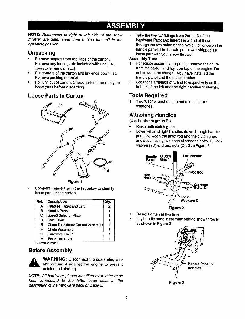
NOTE: References to right or left side of the snowthrower are determined from behind the unit in the
operatingposition.
UnpackingRemove staples fromtop flaps of the carton.Remove any loose parts included withunit (i.e.,operator's manual, etc.).Cut corners of the carton and lay ends down fiat,Remove packing material.
• Roll unit out of carton. Check carton thoroughly forloose parts before discarding.
Loose Parts In Carton
Figure 1
• Compare Figure 1with the list below to identifyloose parts inthe carton.
Ref. Description Qty.A Handles (Right and Left) 2B Handle Panel 1
C Speed Selector Plate 1D Shift Lever 1
E Chute Directional Control Assembl 1
F 3hute Assembly 1G Hardware Pack* 1H Extension Cord 1
• S_own on page 5
Before Assembly
WARNING: Disconnect the spark plug wireand ground it against the engine to preventunintended starting.
NOTE: All hardware pieces identified by a letter codehere correspond to the letter code used in thedescriptionof the hardware pack onpage 5.
• Take the two "Z" fittings from Group D of theHardware Pack and insert the Z end ofthesethroughthe two holes on the two clutchgripson thehandle panel. The handle panel was shipped asloose part withyour snow thrower.
Assembly Tips:1. For easier assembly purposes, removethe chute
from the carton and lay it on top of the engine, Donot unwrap the chute till you have installed thehandle panel and the clutch cables.
2. Lookfor stampinge of L and R respectivelyon thebottom of the left and the right handles to identify.
Tools Required1. Two 7/16" wrenches ora set of adjustable
wrenches.
Attaching Handles(Use hardware group B,)
• Raise bethclutch grips,• Lower left and right handles down throughhandle
panel between the pivot rod and the clutch gripsand attach using two each of carriage bolts (E), lockwashers (C) and hex nuts (D). See Figure 2.
_andle Clutch • Left Handle
_1I'.._ PivotRod
_// " Lock
//Figure 2
• Do nottighten at this time.• Lay handle panel assembly behind snowthrower
as shown in Figure 3,
Handle Panel &Handles
Figure 3

(Usehardware group A.)
• Insert one each of hex bolt (B) and lock washer (C),from Group A of the hardware pack, through thebottomhole in left handle and correspondingholeinsnowthrower housing. See Figure 4. Do nottighten. Repeat on the other side.Raise both handles up until the upper hole in eachhandle align with lhe upper hole on each side of thesnow thrower housing. Secure with hex bolt (A),lock washer (C) and handle tab (I) on each side.See Figure 4,
Left Handle\
Tab I
HexWasher C Bolt A
HexBolt B
Figure 4
Attaching Speed Selector Plate(Use hardware group C.)
• Assemble the speed selector plate to the outsideof the handles as shown in Figure 5. Secure usingtwo self-tappingscrews (F) from hardware group C,Repeat on the other side.
Self-TappingScrews F
Self-TappingScrews F
Figure 5
Attaching Shift Lever(Use hardware group C.)
• Insert the shift leverthroughslot inthe speedselector plate. See Figure 6. The bend in the levershouldbe towards the operator.
Plate
PlexLock Nuts H
Shift LeverSpring
Figure 6
Secure shift lever to the shift lever spring using twohex bolts (G) and hex locknuts (H). See Figure 6.Tighten both bolts finger tight. At this point the shiftlever and shift lever spring are not against eachother. As you tighten the bolts and nuts with twowrenches, these will pull together.Tighten all hardware assembled to this point. Makesure that clutch grips are moving freely.
Attaching Control Cables(Use hardware group D.)
• Since the Z fittingis already inserted into the holeon the clutch gripat thispoint, thread a hex nut (J)from hardware pack D onto each Z fitting. SeeFigure 7.Route the left cable between engine and speedselector plate and then between handle panel andclutch lever pivotrod.Thread cable onto the left"Z" fitting.Assemble the rightcable in the same manner.Both cables should have minimalslack, but nottight. Tighten or loosenhex nutson the "Z" fitting toadjust.
IMPORTANT:If the righthand lock-outcable is notadjusted correctly,the wheels will tend to turn. If the lefthand lock-outcable is not adjusted correctly,theaugers will keep on rotating.
NOTE: Thedriveclutchcab/eisroutedovertheaxle.

A WARNING: Do not over-tighten the clutchcables. Tension on either cable in the
disengaged (up) position may override thesafety features of the machine.
ClutchGrip
Hex Nut J
Figure 7
Attaching Chute Assembly(Use hardware group E,)
• Race chute assembly over chuteopening, with theopening inthe chute assembly facing the front ofthe unit,
• Place chute flange keepers beneath lip of chuteassembly, withthe flat side of chute flange keeperfacing downward, See Figure 8.
ChuteY
Hex Bolt K_Cl_ute Flange -----_
r_eeper
Figure 8
Insert two hex bolts (K) up through each chuteflange keeper and chute assembly as shown inFigure 8. Secure with hex lock nuts (M). Afterassembling all three chute flange keepers, tightenall nuts and bolts securely. Do not over-tighten.
NOTE: Lock nuts cannot be threadedby hand; use two7/16"sized or adjustable wrenches instead.
Attaching Chute Directional Control(Use hardware group F.)• Loosen the two hex nuts which secure the lower
chute directionalcontrol supportbracket (seeFigure 9 inset) to the snow thrower housing,
_ Loosen hex nuts
under this bracket
Hairpin Clip T &Flat Washer S Chute
DirectionalControl
Control Bracket
Figure 9
Place one flat washer (S), fromgroup F, over theend of the chute directional control, then insert theend of the chute directional control into the hole inthe plastic bushing on the chute bracket. SeeFigure 9. Place the remaining flat washer (S) onchute directional control, and secure with hairpinclip (T).Thread one hex nut (D), from group F, onto theeyebolt on the chute directional control assemblyuntil there is at least two inches of threads showingbetween the nut and the eyeboit head. See Figure10 inset.
Place the eyebolt intothe hole located half way upthe left handle. See Figure 10. Secure with cuppedwasher (N) and hex nut (D), from group F, makingsure that the cupped side of the washer is againstthe handle.
e Bolt
DirectionalControl
Figure 10
8

Adjust the chute directional control bracket so thatthe spiral on the chute directional control fullyengages the teeth on the chute assembly. SeeFigure 11. Tighten all hardware.
_ira[should engageteeth of chutehere
Figure 11
Check to make sure all nutsand bolts on the controlpanel and all four boltswhich secure the handles tothe frame are very tight.
Final Assembly & AdjustmentsAuger Control• To check the adjustment of the auger control,push
forward on the left hand clutchgrip (depress therubber bumper). There should be slack inthe cable.Release the clutchgrip. The cabte shouldbestraight. Make certain you can depress the augercontrolgrip against the left handle completely.
• Ifnecessary, loosenthe hex locknutand thread thecable in (for less slack) or out (formore slack) asnecessary. Refer to Figure7.
• Tighten the lock nutagainst the cable when correctadjustment is reached.
Traction Control & Shift Lever
To check the adjustment of the traction control andshift lever, move the shift lever all the way to theright to fifth (5) position. With the traction controlreleased, push the snow thrower forward. The unitshould move forward freely. Then engage thetraction control grip. The wheels should stopturning.Now release the traction control grip, and push theunit again. Move the shift lever back to the fastreverse position, then all the way forward again.There should be no resistance in the shift lever, andthe wheels should keep turning.If you feel resistance when moving the shift lever orthe wheels stop when they should not, loosen thejam nut on the traction control cable and unthreadthe cable one turn.
• If the wheels do not stop when you engage thetraction control grip, loosen the jam nut on thetraction control cable and thread the cable in oneturn.
• Recheck the adjustment and repeat as necessary.Tighten the jam nut to secure the cable whencorrect adjustment is reached.
NOTE: If you are not sure that you have adjustedcorrectly, refer to the Adjustment section onpage 15.
Skid Shoes
The space between the shave plate and the ground canbe adjusted.
a. For close snow removal on a smooth
surface, raise skid shoes higher on the augerhousing. See Figure 12.
b. Use a middle or lower position when the areato be cleared is uneven. See Figure 12.
oe Hex Nuts tr-CarriageBolts
Figure 12
• Adjustskid shoes by loosening the four hex nutsand carriage bolts as shown in Figure 12. Moveskid shoes to desired position.
• Make certain the entire bottom surface of skid shoeis against the ground to avoid uneven wear on theskid shoes. Retighten nuts and bolts securely.
Tire Pressure (Pneumatic Tires)The tiresare overinflated for shipping purposes.
• Check tire pressure. Maintain pressurebetween 15to 20 psi. Refer to tire sidewalls for recommendedtire pressure.
NOTE: If the tire pressure is not equal in both tires, theunitmay puff to one sideor the other.
A WARNING: Maximum tire pressure underany circumstance is 30 psi. Equal tirepressureshould be maintained at all times. Excessivepressure (over 30 psi) when seating beadsmay cause tire/rim assembly to burst withforce sufficient to cause serious injury.
IMPORTANT:After assembly, service enginewithgasoline, and check oillevel as instructedin theseparate engine manual packed with your unit.
9

Knowing your Snow Thrower
,_ WARNING: Be familiar with all the controlsand their proper operation. Know how to stop the machineand disengage them quickly.•, --Traction Control
Shift Lever
Gas Fill \
b_ Auger Control
Discharge Chute --- Chute DirectionalControl
Auger
Skid Shoe
Spark Plug _ _ 1
/
Ignition Key___X |
Throttle Le_er "_ RecoilStarter_
Figure 13
Operating ControlsShift Lever
The shiftlever is located below the handle panel. SeeFigure 13. The shift lever may be moved into one ofseven positions.Run engine withthrottle inthe fastposition.Use the shift lever to determine groundspeed.There are five forward and two reverse speeds on thissnowthrower. Among the forward speeds, positionone(1) isthe slowest and positionfive (5) is the fastest.Among reverse speeds, R2 is the faster.
Auger ControlThe auger control is located on the left handle.Squeeze the auger controlgripto engage the augers.Release to stopthe augers. See Figure 13.
Traction Control
The tractioncontrolis located on the righthandle.Squeeze the tractioncontrol gripto engage the wheeldrive. Release to stop. See Figure 13.
Throttle Control
The throttlecontrolis located on the engine. It regulatesthe speed of the engine. See Figure 13.
Chute Directional Control
The chute directional controlis located on left side ofthe snow thrower. See Figure 13. To change thedirection in which snow is thrown, turn chute directionalcontrol as follows:
• Crank clockwise to discharge to the left.• Crank counterclockwise to discharge to the right.
Ignition Key
The ignitionkey must be inserted inthe switchbeforethe unit willstart. See Figure 13 inset. Remove theignition kay when snow thrower is not in use. Do notturn ignitionkey.
Stopping the engine• To stop engine, move throttle controlto "stop" or
"off" position.Remove the ignitionkey. Do not turnkey.
• Disconnect the spark plug wire fromthe spark plugto prevent accidental starting while equipment isunattended.
10
Before Starting
WARNING: Read, understand, and followall instructions and warnings on the machineand in this manual before operating.
• The engine was shipped withoil. Check the oil levelbefore operating. After the initial use, you will haveto fill up as necessary. Be careful not to overfill.
• Before filling up gas in the engine for the first time,open the gas tank cap, and locate a white plasticcap underneath. Remove this cap and discard it.
• The spark plug wire was disconnected for safety.Attach spark plug wire to spark plug before starting.
Before Starting EngineFill Gas
& WARNING: Gasoline is flammableand cau-tion must be usedwhen handlingor storing it.
Do not fill fuel tank while the snow thrower isrunning, when it is hot or when it is in anenclosed area.
Keep your snow thrower away from any openflame or an electrical spark and do not smokewhile filling the fuel tank.
Never fill the fuel tank completely. Fill the tankto within 1/4"-1/2" from the top to providespace for expansion of fuel.
Always fill the fuel tank outdoors and use afunnel or spout to prevent spilling.
Make sure to wipe off any spilled fuel beforestarting the engine.
• Store gasoline ina clean, approved containerandkeep the cap in place on the container.Make sure that the container from which you pourthe gasoline is clean and free from rust or otherforeignparticles.
• Fillfuel tank with clean, fresh, unleaded gradeautomotive gasoline.
• At the end of the job, empty the fuel tank ifthesnowthrower is not going to be used for 30 daysorlonger. See storage instructionson page 19 ofthismanual.
CAUTION: Experience indicatesthat alcohol blendedfuels (called gasohol) or those using ethanol ormetha-nol can attract moisture which leads to separation andformation of acids during storage.
Acidic gas can damage the fuel system of an enginewhile in storage.
To avoid engine problems, the fuel system should beemptied before storage for 30 days or longer. Drain thegas tank, start the engine and let it run until the fuel lines
and carburetorare empty.Use fresh fuel nextseason.See storage Instructions for additionalinformation.
Never use engine or carburetor cleaner products in thefuel tank or permanent damage may occur.
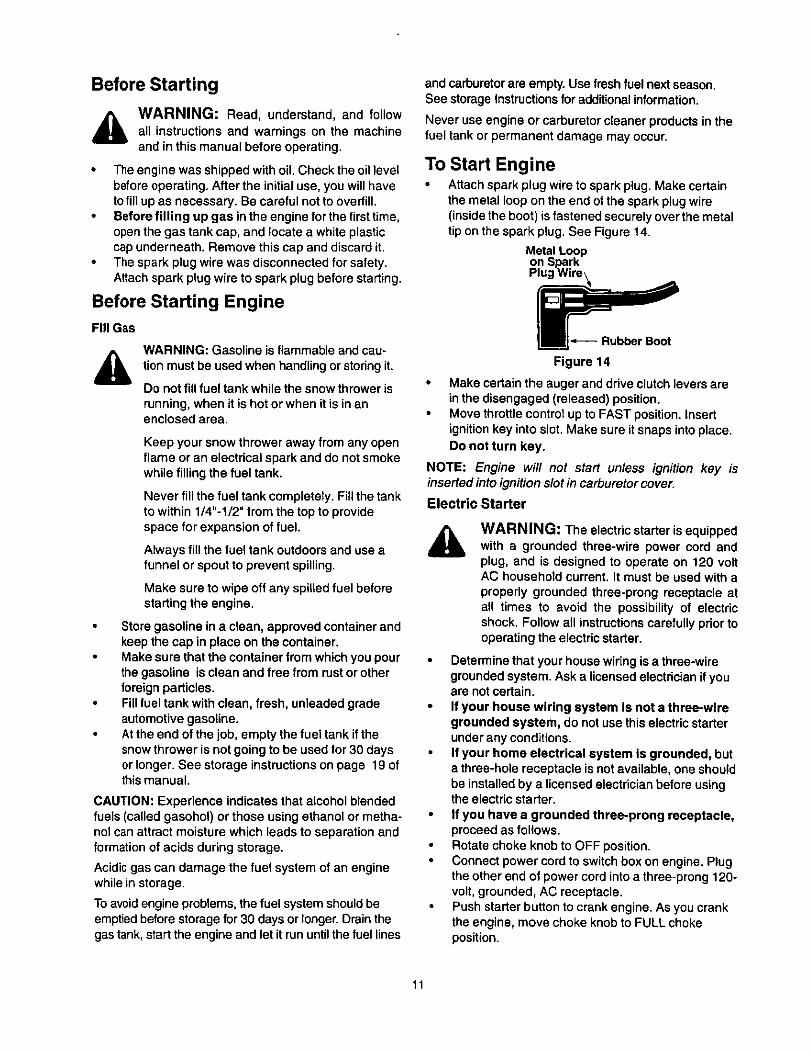
To Start Engine• Attach spark plug wire to spark plug. Make certain
the metal loop on the end of the spark plug wire(inside the boot) is fastened securely over the metaltip on the spark plug. See Figure 14.
Figure 14
Make certain the auger and drive clutch levers arein the disengaged (released) position.Move throttle control up to FAST position. Insertignition key into slot. Make sure it snaps into place.Do not turn key.
NOTE: Engine will not start unless ignition key isinserted into ignitionslot in carburetor cover.
Electric Starter
WARNING: The electric starter is equippedwith a grounded throe-wire power cord andplug, and is designed to operate on 120 voltAC household current. It must be used with aproperly grounded three-prong receptacle atall times to avoid the possibility of electricshock. Follow all instructionscarefullyprior tooperating the electric starter.
Determine that your house widng is a three-wiregrounded system. Ask a licensed electrician if youare not certain.If your house wiring system Is not a three-wiregrounded system, do notuse this electricstarterunder any conditions.If your home electrical system is grounded, buta three-hole receptacle is not available, one shouldbe installed by a licensedelectricianbefore usingthe electric starter.
If you have a grounded three-prong receptacle,proceedas follows.Rotate choke knob to OFF position.Connect power cord to switchbox on engine. Plugthe other end of power cord intoa three-prong 120-volt, grounded, AC receptacle.Push starterbutton to crank engine. As youcrankthe engine, move choke knob to FULL chokeposition,
11
When engine starts, release starter button, andmove choke gradually to OFF. If engine falters,move choke immediately to FULL and thengradually to OFF.When disconnecting the power cord, always unplugfrom the three-prong receptacle first, and then fromthe snow thrower.
Recoil Starter
• Rotate choke knob to FULL choke position (coldengine start).
• If engine is warm, place choke in OFF positioninstead of FULL.
• Push primer button two or three times for coldengine start.
• If engine is warm, push primer button only once.
NOTE: Always cover vent hole in primer button whenpushing. Additional priming may be necessary for firststart if temperature is below 15 degrees Fahrenheit.
• Grasp starter handle and pull rope out slowly,untilit pulls slightlyharder. Let rope rewind slowly.
• Pull starter handle rapidly. Do not allow handle tosnap back. Allow it to rewind slowly while keeping afirm hold on the starter handle.
• As engine warms up and begins to operate evenly,rotate choke knob slowly to OFF position. If enginefalters, return to FULL choke, then slowly move toOFF position.
To Stop EngineRun engine for a few minutes before stopping tohelp dry off any moisture on the engine.
• To help prevent possible freeze-up of starter,proceed as follows.
Electric Starter
• Connect power cord to switch box on engine, thento 120 voltAC receptacle. With the engine running,
push starterbutton and spin the starter for severalseconds. The unusual sound made by spinning thestarter will not harm engine or starter. Disconnectthe power cord from receptacle first, and then fromswitch box.
Recoil Starter
• With engine running, pull starter rope witha rapid,continuous full arm stroke three or four times.Pulling the starter rope will produce a loud clatteringsound, which is not harmful to engine or starter.To stop engine, move throttle control to "stop" or"off" position.
• Remove the ignitionkey. Do not turn key.• Disconnect the spark plug wire from the spark plug
to prevent accidental starting while equipment isunattended.
NOTE: Do not lose ignition key. Keep it in a safe place.Engine will not start without the ignition key.
• Wipe all snow and moisture from the carburetorcover in the area of the control levers. Also, movecontrol levers back and forth several times.
To Engage Drive• With the engine running near top speed, move shift
lever intoone of the five FORWARD positionsortwo REVERSE positions. Select a speedappropriatefor the snow conditionsthat exist.Usethe slower speeds untilyou are familiarwiththeoperationof the snow thrower.
• Squeeze the auger control grip and the augers willturn. Release it and the augers will stop.
• Squeeze tractioncontrol grip and the snowthrowerwillmove. Release it and drive motionwillstop.NEVER move shift lever withoutreleasing driveclutch.
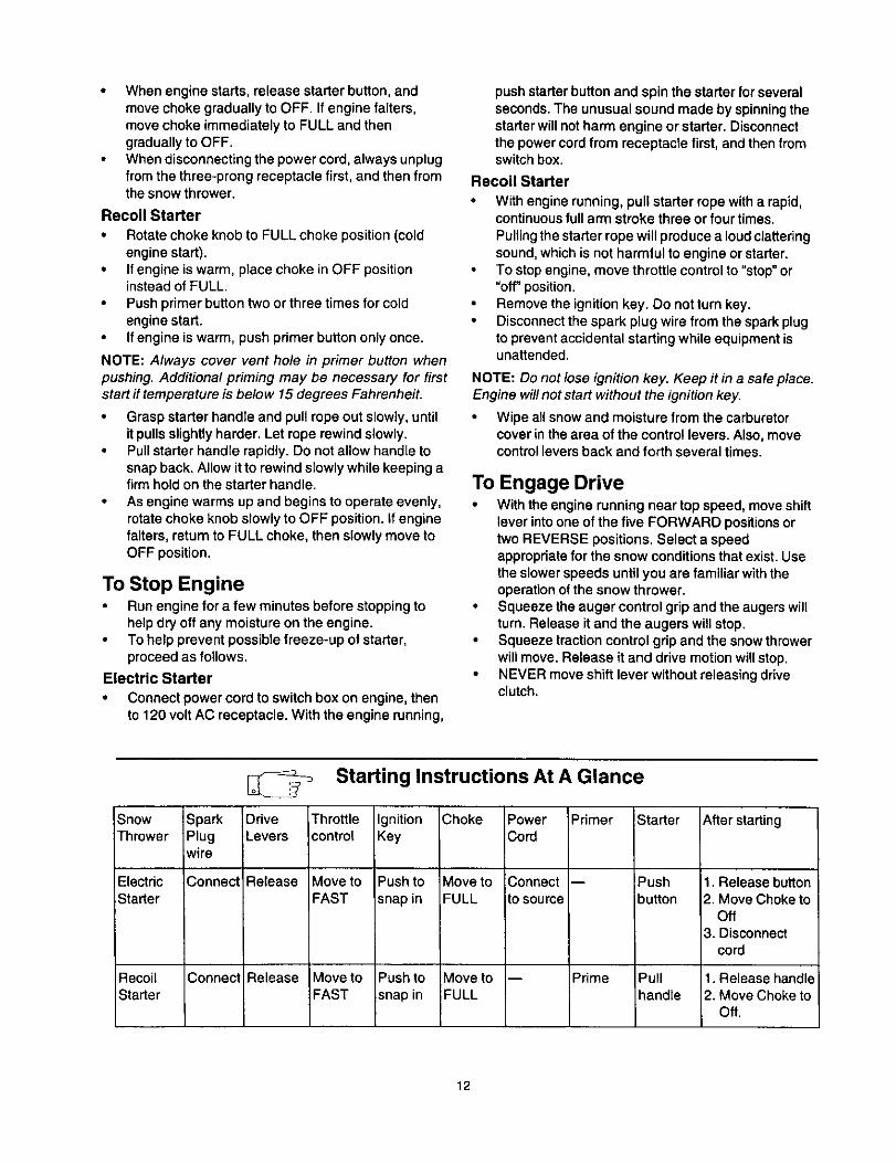
Snow SparkThrower Plug
wire
Electric ConnectStarter
Recoil ConnectStarter
Starting Instructions At A Glance
Drive ,ThrottleLevers control
Release Move toFAST
Release Move toFAST
IgnitionKey
Push to
snap in
Push tosnap in
Choke
Move toFULL
Move toFULL
PowerCo_
Connect
to source
Primer
Prime
Starter
Pushbutton
Pullhandle
After starting
1. Release button2. Move Choke to
Off3. Disconnect
cord
1. Release handle2. Move Choke to
Off.
12

To Engage Augers• To engage the augers and start throwingsnow,
squeeze the auger controlgrip against the lefthandle. Release to stopthe augers.
Operating Tips• Allowthe engine to warm up for a few minutesas
the engine will notdevelop futtpower until itreachesoperating temperature.
_k WARNING: Muffler, engine and surroundingareas become hot and can cause a burn. Donottouch.
• For most efficientsnowremoval, remove snowimmediately after it falls.
• Discharge snow downwind whenever possible.Slightly overlap each previous swath.
• Set the skidshoes 1/4"below the scraper bar fornormal usage. The skidshoes may be adjustedupward for hard-packed snow. Adjustdownwardwhen usingon gravel or crushed rock.
• Be certain to follow the precautionslistedunder "ToStop Engine" to prevent possiblefreeze-up.
• Clean the snowthrowerthoroughlyafter each use.
Tire Chains (ifequipped)• Tire chains, if your snowthrower is so equipped,
should be usedwhenever extra tractionis needed.
General RecommendationsAlwaysobserve safety ruleswhen performinganymaintenance.
• The warranty on thissnow thrower does not coveritems that have been subjected to operator abuseor negligence. To receive full value from thewarranty, operator must maintain the snow throweras instructed inthis manual.
Some adjustmentswillhave to be madeperiodically to maintainyour unit properly.All adjustments in the Service and Adjustmentssection of this manual should be checked at leastonce each season.Follow the maintenance schedule given below.Periodically check all fasteners and make surethese are tight.
Customer Responsibilities
MAINTENANCE SCHEDULE _ v-'_ <_P _ ¢ _ SERVICE DATES*
Lubricatepivotpoints ,_ '_
(_ Clean snowthrower _ '_
8 Clean shaveplateClean skidshoes
Check V-belts
Check frictionwheel _¢2rubber
Check engineoil
uJ Change engineoil _z
_Z Check spark plug _ <_LIJ
Check muffler
Emptyfuel system ,_
• Fill in dates as you complete regular serviceCheck; service ifneeded
13
Lubrication
& WARNING: Before lubricating, repairing, orinspecting, disengage all clutch levers andstop engine. Wait until all moving parts havecome to a complete stop. Disconnect sparkplug wire and ground it against the engine toprevent unintended starting.
iMPORTANT:When lubricating engine or draining oil,avoid drippingoil onto transmissionparts.
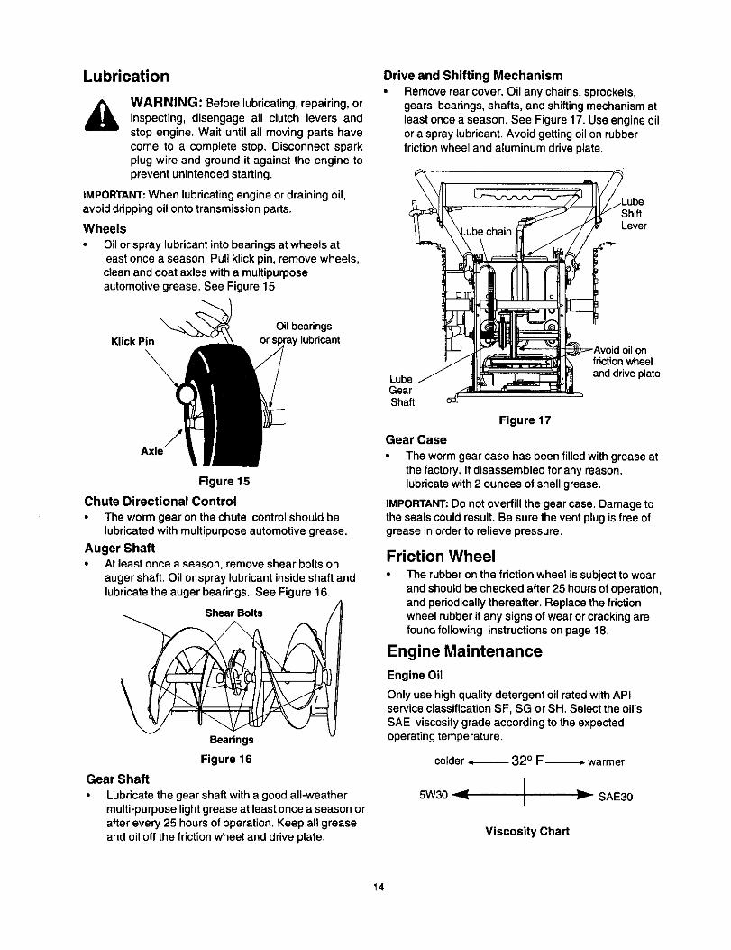
Wheels
Oil or spray lubricant into bearings at wheels atleast once a season. Pull klick pin, remove wheels,clean and coat axles with a multipurposeautomotive grease. See Figure 15
Drive and Shifting Mechanism• Remove rear cover. Oil any chains,sprockets,
gears, bearings,shafts, and shiftingmechanism atleast oncea season. See Figure 17. Use engine oilor a spray lubricant. Avoidgettingoil on rubberfriction wheel and aluminum drive plate.
Lever
KlickPin
\Oil bearings
' lubricant
Figure 15
Chute Directional Control
• The worm gear on the chute control should belubricatedwith multipurposeautomotive grease.
Auger Shaft• At least once a season, remove shear bolts on
auger shaft. Oil or spray lubricant insideshaft andlubricatethe auger bearings. See Figure 16.
Shear Bolts
Bearings
Figure 16
Gear Shaft
Lubricate the gear shaft with a good all-weathermulti-purposelightgrease at least once a season orafter every 25 hours of operation. Keep al! greaseand oil oft the friction wheel and drive plate.
LubeGearSha_
Gear Case
)nfriction wheel
and drive plate
Figure 17
• The worm gear case has been filledwithgrease atthe factory. If disassembled for any reason,lubricatewith2 ounces of shell grease.
iMPORTANT:Do not overfill the gear case. Damage tothe seals couldresult. Be sure the vent plugis free ofgrease inorderto relieve pressure.
Friction WheelThe rubber on the friction wheel is subjectto wearand should be checked after 25 hours of operation,and periodically thereafter. Replace the frictionwheel rubber if any signs of wear or cracking arefound following instructions on page 18.
Engine Maintenance
Engine Oil
Only use high qualitydetergent oil rated withAPIservice classificationSF, SG or SH. Select the oil'sSAE viscosity grade according to the expectedoperating temperature.
colder _ 320 F_ warmer
I _ SAE305w3o I
Viscosity Chart
14
NOTE: Althoughmulti-viscosity oils (5W30, 10W30etc.) improve startingin cold weather, these multi-viscosity oils will result inincreased oil consumptionwhenused above 32°F. Check your snow thrower'sengine oil level more frequently to avoid possibleengine damage from running low on oil
Referto the viscositychart for proper selectionofengineoil. Do not use SAE 10W40 oil.
Checking Oil Level
Before operating the snow thrower, check the oillevel. With engine on level ground, the oil must beto FULL mark on dipstick.Stop engine and wait several minutes beforechecking oil level. Remove oil fill cap and dipstick.Wipe dipstick clean, insert it into oil fill hole andtighten securely.Remove dipstick and check. If oil is not up to theFULL mark on dipstick, add oil.
Changing Oil
Change engine oil after first two hours of operationandevery 25 hours thereafter.In order to change the oil, you will have to first drain thespent engine oil from the engine and then refill withfresh oil.
• Drain oil while engine is warm. Remove oil draincap located at the bottom of the recoil starter of theengine. Catch oil in a suitable container.When engine is drained of all oil, replace drain plugsecurely.
• Remove the dipstick from the oil fill. Pour fresh oilslowly through the plug. Replace dipstick.
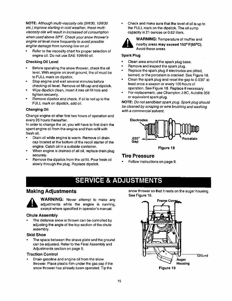
Check and make sure that the level of oil is up tothe FULL mark on the dipstick. The oil sumpcapacity is 21 ounces or 0.62 liters.
_k WARNING: Temperature of muffler andnearby areas may exceed 150° F(65°C).Avoidthese areas.
Spark Plug
• Clean area around the spark plug base.• Remove and inspect the spark plug.
Replace the spark plug if electrodes are pitted,burned, or the porcelain is cracked. See Figure 18.
• Clean the spark plug and reset the gap to 0.030" atleast once a season or every 100 hours ofoperation. See Figure 18. Replace if necessary.For replacement, use Champion J-8C, Autolite 356or equivalent spark plug.
NOTE: Do not sandblast spark plug. Spark plug shouldbe cleaned by scraping or wire brushing and washingwith a commercial solvent.
Gap
Figure 18
Tire Pressure• Follow instructionson page 9.
Making Adjustments
,_ WARNING: Never attempt to make anyadjustments while the engine is running,except where specified inoperator's manual.
Chute Assembly
The distance snow is thrown can be controlledbyadjustingthe angSeof the top section ofthe chuteassembly.
Skid Shoe
• The space between the shave plate and the groundcan be adjusted. Refer to the Final Assembly andAdjustments section on page 9.
Traction Control
Drain gasoline and engine oil from the snowthrower. Place plastic film under the gas cap if thesnow thrower has already been operated. Tip the
snow thrower so that it rests onthe auger housing.See Figure 19.
AugerHousing
Figure 19
15

Remove the frame cover underneath the snowthrower by removing six self-tapping screws. Forlocationof the frame cover, see Figure 19.
• When the traction control is released, there mustbeclearance between the friction wheel and the driveplate in all positions of the shift lever. When thetraction control is engaged, the fdction wheel mustcontact the drive plate. See Figure 20.
Figure 20
• If any one of these are not occuring, adjustmentisnecessary. Follow the steps below to adjust thetractioncontrol.
• Loosenthe locknut on the tractioncontrolcable
and thread the cable in or out as necessary.Tighten the lock nut to secure the cable whencorrect adjustment is reached. Reassemble theframe cover.
NOTE: ff you placed plastic under the gas cap earlier,remove it now.
Auger Control
• To adjust the auger clutch, refer to FinalAssemblyand Adjustments on page 9.
Carburetor
A WARNING: If any adjustments need to bemade to the engine while the engine is running(e.g. carburetor), keep clear of all movingparts. Be careful of muffler, engine and othersurrounding heated surfaces.
Minor carburetor adjustment may be required tocompensate for differences in fuel, temperature,altitude and load.
Drive Wheels
• The wheels may be adjusted for two differentmethods of operation. Follow the steps below foradjustment. See Figure 21.
Hole in Axle
Figure 21
One Wheel Driving• On the right side of the unit,place klick pin in the
outsideaxle hole only. Do not place pin throughwheel hub.This positiongives power drive to theleft wheel only, making the uniteasier to maneuver.
Both Wheels DrivingRotate wheel assembly to alignhole inthe hub withthe inner hole on the axle shaft. Insert klickpin inthe hole. Outer axle shaft hole should be visible.See Figure 21.
A WARNING: Before servicing, repairing, orinspecting, disengage all clutch levers andstop engine. Wait untilall moving parts havecome to a complete stop. Disconnect sparkplug wire and ground it against the engine toprevent unintended starting.
Servicing AugersThe augers are secured to the spiralshaft with twoshear bolts and hex lock nuts.See Figure 16. Ifyouhit a hard foreign object or ice jam, the snowthrower is designed so that the bolts may shear.
• If the augers will not turn,check to see if the boltshave sheared. Replacement shear boltsand hexlocknuts have been providedwith the snowthrower. When replacing bolts,spray an oillubricant intoshaft before insertingnew bolts.
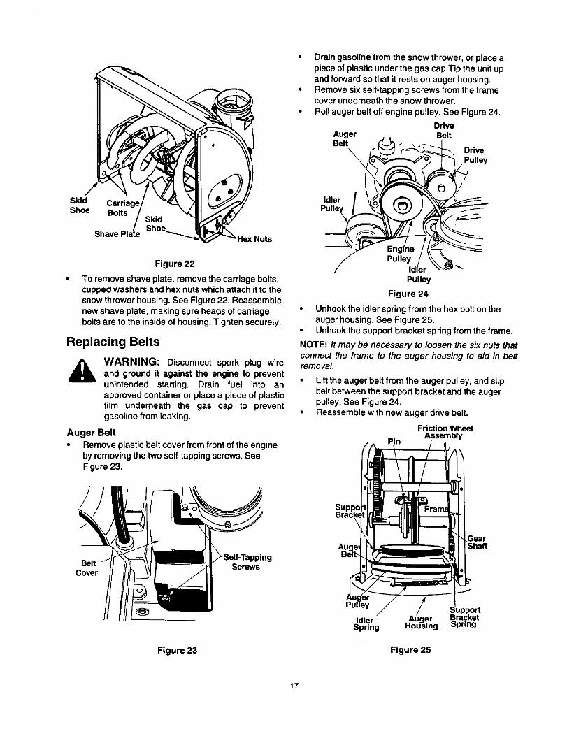
Shave Plate and Skid ShoesThe shave plate and skidshoes on the bottom ofthe snow thrower are subject to wear. They shouldbe checked periodically and replaced whennecessary.To remove skid shoes, remove the four carriagebolts, cupped washers and hex nuts which attachthem to the snow thrower. Reassemble new skidshoes with the four carriage bolts, cupped washers(cupped side goes against skid shoes) and hexnuts. See Figure 22.
16
Skid
Shoe Bolts
Figure 22
To remove shave plate, remove the carriage bolts,cupped washers and hex nuts which attach it to thesnowthrower housing.See Figure 22. Reassemblenew shave plate, making sure heads of carriageboltsare to the inside of housing.Tighten securely.
Replacing Belts
WARNING: Disconnect spark plug wireand ground it against the engine to preventunintended starting. Drain fuel into anapproved container or place a piece of plasticfilm underneath the gas cap to preventgasoline from leaking.
Auger Belt• Remove plastic beltcover from front of the engine
by removing the two self-tappingscrews. SeeFigure23.
Drain gasoline from the snow thrower, or place apiece of plastic under the gas cap.Tip the unit upand forward so that it rests on auger housing.Remove six self-tapping screws from the framecover underneath the snow thrower,Roll auger belt off engine pulley. See Figure 24.
DriveAuger BeltBelt L"_ r- \_T _i .
\ i_ '_ _;__-_'_, Drive
/_('_l_"_/ ' _. _ Pulley
/ Pulley / \\ "_/ IdI,' \_L-_ _-
Pulle
Figure 24
• Unhookthe idler springfrom the hex bolt ontheauger housing. See Figure 25.Unhook the support bracket spring from the frame.
NOTE: It may be necessary to loosen the six nuts thatconnect the frame to the auger housing to aid in beltremoval.
• Liftthe auger belt from the auger pulley, and slipbelt between the support bracket and the augerpulley, See Figure 24.
• Reassemble with new auger drive belt.
Friction Wheel
Pin Assembly
BeltCover
Figure 23
Screws
/Idler Auger
Spring Housing
Figure 25
Gear
17
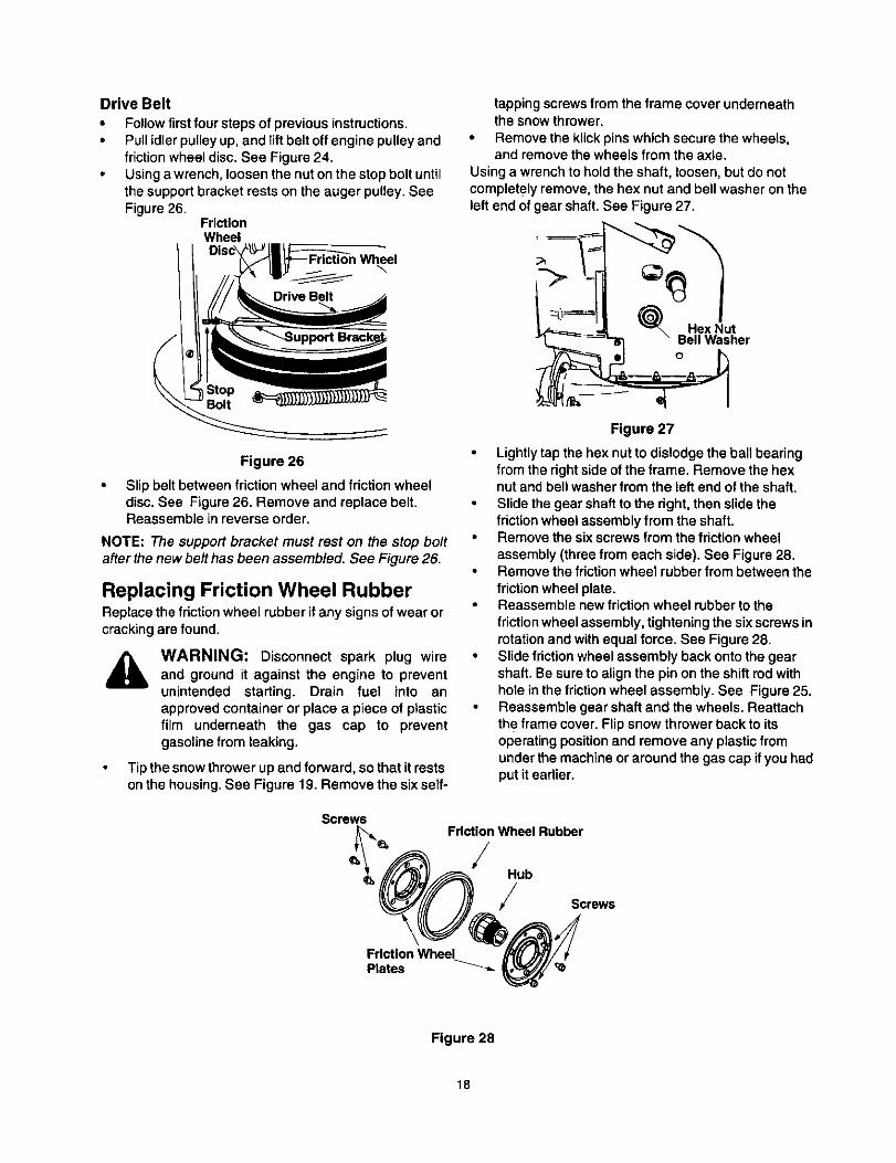
Drive Belt
• Follow first foursteps of previous instructions.• Pull idler pulley up, and liftbelt off engine pulley and
friction wheel disc. See Figure 24.• Using a wrench, loosen the nut on the stop bolt until
the support bracket rests on the auger pulley. SeeFigure 26.
FrictionWheel
\
Figure 26
Slip belt between friction wheel and friction wheeldisc. See Figure 26. Remove and replace belt.Reassemble in reverse order.
NOTE: The supportbracket must rest on the stop boltafter the new belt has been assembled. See Figure 26.
Replacing Friction Wheel RubberReplace the friction wheel rubber if any signs of wear orcrackingare found.
WARNING: Disconnect spark plug wireand ground it against the engine to preventunintended starting. Drain fuel into anapproved container or place a piece of plasticfilm underneath the gas cap to preventgasolinefrom leaking.
Tip the snow thrower up and forward, so that it restsonthe housing.See Figure 19. Remove the six self-
tapping screws from the frame cover underneaththe snow thrower.
• Remove the klick pins which secure the wheels,and remove the wheels from the axle.
Using a wrench to hold the shaft, loosen, but do notcompletely remove, the hex nut and bell washer on theleft end of gear shaft. See Figure 27.
Uter
Figure 27
Lightly tap the hex nut to dislodge the ball bearingfrom the right sideof the frame. Remove the hexnut and bell washer from the left end of the shaft.Slide the gear shaft to the right, then slide thefriction wheel assembly from the shaft.Remove the six screws from the friction wheelassembly (three from each side). See Figure 28.Remove the friction wheel rubber from between thefriction wheel plate.Reassemble new friction wheel rubber to the
friction wheel assembly, tightening the six screws inrotation and with equal force. See Figure 28.Slide friction wheel assembly back onto the gearshaft. Be sure to align the pin on the shift rod withhole in the friction wheel assembly. See Figure 25.Reassemble gear shaft and the wheels. Reattachthe frame cover. Flip snow thrower back to itsoperating position and remove any plastic fromunder the machine or around the gas cap if you hadput it earlier.
Screws
FrictionWheel Rubber
/Hub
Screws
Friction WheelPlates '_
Figure 28
18

Ifthe snow thrower will not be used for 30 days orlonger, or at the end of the snow season when the tastpossibility of snow is gone, the equipment needs to bestored properly. Follow storage instructions below toensure top performance from the snow thrower formany more years.
Preparing Engine
WARNING: Never store snow thrower with
fuel in tank indoors or in poorly ventilatedareas, where fuel fumes may reach an openflame, spark or pilot light as on a furnace,water heater, clothes dryer or gas appliance.
It is important to prevent gum deposits fromforming in essential fuel system parts of theengine such as the carburetor, fuel filter, fuelhose or tank during storage.
Also experience indicates that alcoholblended fuels (called gasohol or using ethanolor methanol) can attract moisture which leadsto separation and formation of acids dudngstorage. Acidic gas can damage the fuelsystem of an engine while in storage.
To avoid engine problems, the fuel systemshould be emptied before storage for 30 daysor longer. Follow these instructions to prepareyour snow thrower for storage:
Remove all gasoline from the carburetor and thefuel tank to prevent gum deposits from forming onthese parts and harming the engine.
Carbure__
BowS- -- Drain
Figure 29
WARNING: Drain fuel into approvedcontainer outdoors, away from any openflame. Be certain engine is cool. Do notsmoke.
Fuel left in engine during warm weatherdeteriorates and will cause serious startingproblems.
Run the engine until the fuel tank is empty and itstops due to lack of fuel.Drain carburetor by pressing upward on bowl drain,located below the carburetor cover. See Figure 29.
WARNING: Do not drain carburetor if usingfuel stabilizer. Never use engine or carburetorcleaning products in the fuel tank orpermanent damage may occur.
NOTE: Fuel stabilizer (such as STA-BIL) is anacceptable alternative in minimizing the formation offuel gum deposits during storage. Add stabilizer togasoline in fuel tank or storage container. Always followmix ratio found on stabilizer container. Run engine atleast 10 minutes after adding stabilizer to allow it toreach the carburetor. Do not drain carburetor ff usingfuelstabilizer.
Remove the spark plug and pour one (1) ounce ofengine oil through the spark plug hole into thecylinder. Cover spark plug hole with a rag and crankthe engine several times to distribute the oil.Replace spark plug.
Preparing Snow Thrower• When storingthe snow throwerin an unventilated
or metal storage shed, care should be taken torustproofthe equipment.Using a lightoilor silicone,coat the equipment, especiallyany chains,springs,bearings and cables.
• Remove all dirt fromexterior of engine andequipment.
• Follow lubricationrecommendations on page 14.• Store in a clean, dry area.
19

Trouble Possible Cause(s) Corrective ActionEnginefails to start Fuel tankempty,orstalefuel.
Engine runs erratic
Water or dirt in fuel system.Loss of power Spark plugwire loose.
Gas cap vent hole plugged.Exhaust port plugged.
Engine overheats Carburetor not adjustedproperly.
Blocked fuel line.
Choke not inON positionFaulty spark plug.Key not in switch on engine.Spark plug wire disconnected.Primer button not depressed.Unit running on CHOKE.Blocked fuel line or stale fueL
Fill tank withclean, fresh gasoline. Fuel willnot last over thirtydays unless a fuel stabilizer is used.Clean fuel line,
Move switch to ON positionClean, adjust gap or replace.Insert key.Connect spark plug wire.
Prime engine 5 times. See instructions for starting engine.Move choke lever to OFF position.Clean fuel line; fill tank with clean fresh gasoline. Fuel will not lastover thirty days unless a fuel stabilizer is used.Drain fuel tank. Refill with fresh fuel.Connect and tighten spark plug wire.Remove ice and snow from cap. Be certain vent hole is clear.Clean engine.Contact Sears service center.
Incorrect fuelmixture. Drain fuel tank. Refill with proper fuel mixture.Excessive vibration Loose parts or damaged Stop engine immediately and disconnect spark plug wire. Tighten
auger, allbolts and nuts. Make all necessary repairs. If vibrationcontinues, have unit serviced by an authorized service dealer.
Unit fails to propel Incorrect adjustment of drive Adjust drive cable. Refer to page 9 of this manual.itself cable.
Drive belt loose or damaged.Unit fails to Discharge chute clogged.discharge snow
Foreign object lodged inauger.Incorrect adjustment of drivecable.
Drive belt loose or damaged.Shear bolts have sheared.
Replace drive belt. Refer to page 17 of this manual.
Stop engine immediately and disconnect spark plug wire. Cleandischarge chute and inside of auger housing.Stop engine immediately and disconnect spark plug wire. Removeobject from auger.,Adjust drive cable. Refer to page 9 of this manual.
Replace drive belt. Refer to page 17 of this manual.Replace with new shear bolts.
NOTE: For repairs beyond the minor adjustments listed above, please contact your nearest Sears service center.
20

SEARS CRAFTSMAN 5.0 H.P. SNOW THROWER MODEL 247.886640
Safety & Decorative Labels Map
777120329
777D04651
777120330
777120327
7T/$30514
!1
777D04650
7"r/D04649
_ FRAM ER_j_'_DEPERiF
21
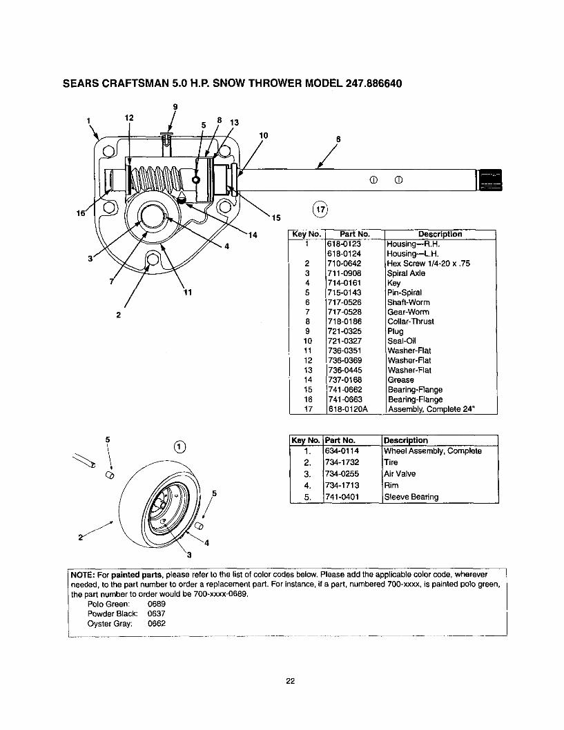
SEARS CRAFTSMAN 5.0 H.P. SNOW THROWER MODEL 247.886640
129
5
11
13
10 6
/• ©
15
Key No.1
Part No.618-0123618-0124
2 710-06423 711-09084 714-01615 715-01436 717-05267 717-05288 718-01869 721-032510 721-032711 736-035112 736-036913 736-044514 737-016815 741-066216 741-066317 618-0120A
DescriptionHousing--R.H.Housing--L.H,,Hex Screw 1/4-20 x .75
Spiral AxleKeyPin-Spiral_haft-Worm
Gear-WormCollar-ThrustPlugSeal-OilWasher-FlatWasher-FlatWasher-FlatGrease
Bearing-FtengeBearing-FlangeAssembly, Complete 24"
5®
5
/
Key No. Pa_ No.1. 634-0114
2. 734-1732
3. 734-0255
4. 734-1713
5. 741-0401
Description
Wheel Assembly, CompleteTire
Air Valve
Rim
Sleeve Bearing
NOTE: For painted parts, please refer to the list of color codes below. Please add the applicable color code, whereverneeded, to the part number to order a reptacement part. For instance, if s part, numbered 700-xxxx, is painted polo green, |the part number to order would be 700-xxxx-0689. I
Polo Green: 0689 [Powder Black: 0637 /Oyster Gray: 0662 |
i ...................................................
22

SEARS CRAFTSMAN 5.0 H.P. SNOW THROWER MODEL 247.886640
IMPORTANT: For a proper workingmachine, use Factory Approved Parts.V-BELTS are specially designed to engageand disengage safely. A substitute (nonOEM) V-Belt can be dangerous by notdisengagingcompletely.
22
2415
\ \
14 26
24
\
2_ 27
2%
KeyNo.1.2.3.4.5.6.7,8.9_10.11,12.13,14.15.16
PaN No.
05896A710-0230
i710-0627710-0654A
710-0696710-1245
710-1652710-3005
712-0181
731-1324732-0339
736-0242736-0247
736-0270
736-0331736-0505
Description
Idler Bracket
Hex Bolt 1/4-28 x 0.50"
Hex Bolt: Lock 5/16-24 x .750"
Self-Tapping Sems ScrewHex Bolt 3/8-24 x ,875"Hex Bolt : Lock 5/16-24 x .875"
Self-Tapping ScrewHex Screw 3/8-16 x 1.25"
aty, Key Part No. Description
Jam NutBelt Cover
Extension SpringBeleville WasherFlat Washer
Bell WasherBell Washer
Flat Washer
1
1
24
11
21
NO.
17.
18.19.
20.21.
22.23.
24.25.
26.27.
28.29.
736-0507737-3007
748-0234748-0360
754-0343754-0430A
756-0313
756-0569756-0967
756_0984756-0985
629-0071
Special WasherGrease
Shoulder Spacer
Pulley: AdapterV-BeltBelt
Idler: Flat
Pulley: Half1
1
11
1
11
1
30, 770-10433
Auger PulleyPulley Half
Pulley HalfExtension Cord
Engine, Craftsman model143.015007Operator's Manual (not shown)
11
11
1
21
11
1
23
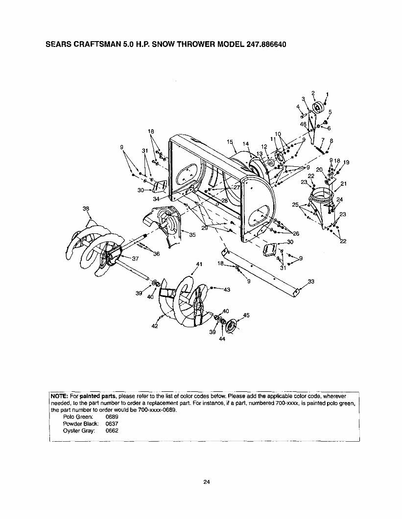
SEARS CRAFTSMAN 5.0 H.P. SNOW THROWER MODEL 247.886640
1
\
18
3114
21
41/
3944
%
NOTE: For painted parts, please refer to the list of color codes betow.Please add the applicable color code, whereverneeded, to the part number to order a replacement part. For instance, ifa part, numbered 700-xxxx, is painted polo green,the part number to order would be 700-xxxx÷0689.
Polo Green: 0689Powder Black: 0637
Oyster Gray: 0662
24

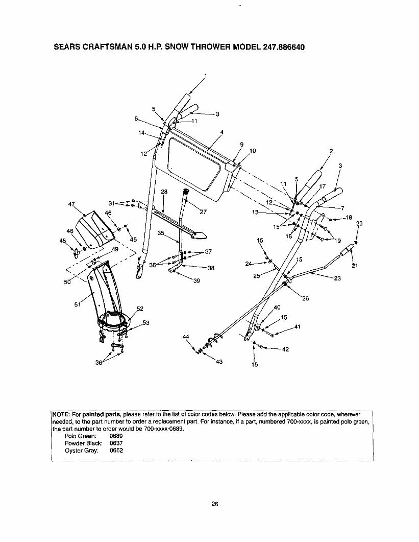
SEARS CRAFTSMAN 5.0 H.P. SNOW THROWER MODEL 247.886640
I Key No. PaN No,1 712-01162 756-01783 784-5632A4 710-0459A5 738-02815 736-01677 732-06118 712-30689 712-30t010 736-011911 0593112 741-030913 710-045114 705-522615 684-0039C17 736-011918 736-024219 741-047520 784-564721 731-1379B22 712-032423 736-0463
DescriptionLock Jam Nut 3/8-24Flat IdlerAuger Idler ArmHex Cap Screw 3/8-24 x 1.50Shoulder ScrewFlat WasherExtension SpringHex Nut 5/16-t8Hex Nut 5/16-18Lock Washer 5/16Bearing HousingBall BearingCarriage Bolt 5/16-18Reinforcement ChuteHousing AssemblyLock Washer 5/16Bell WasherBushingChute Crank Bracket
Chute AdapterHex Lock Nut 1/4-20IFlat Washer
Qty.11111111139I1411131011555
Key No.24252627282930313334353637*383940414243444546
Part No.710-0451710-0703710-0604736-0169712-0798710-0451784-5580736-0242784-5581A710-0260684-00657t5-0114618-0120A605-5188A736-0188741-0493A605-5189A710-0890A712-0429741-0245784-5618
Description Qty.Carriage Bolt 6Carriage Screw 1/4-20 x .75 1Hex Washer Screw 5/16-18 1Lock Washer 3/8 4Hex Nut 3/8-16 2Carriage Bolt5/16-18 x .75 4Skid Shoe 2Bell Washer 4Shave Plate 1Carriage Bolt 5/16-18 x ,62 2Impeller Assembly 1Roll Pin 2Gear Assembly 1Spiral RH 1Flat Washer 4Flange Bushing 4Spiral LH 1Shear Bolt 5/16-18 x 1.5 2Lock Nut 5/16-18 2Hex Flange Bearing 2Bearing Housing 1Grease
• See page 22 for breakdown ol this assembly.
25
SEARS CRAFTSMAN 5.0 H.P. SNOW THROWER MODEL 247.886640
53
6_
4
<
910 2
40
44
\
NOTE: For painted parts, please refer to the list of color codes below. Please add the applicable color code, whereverneeded, to the part number to order a replacement part. For instance, if a part, numbered 700-xxxx, is painted polo green,the part number to order would be 700-xxxx-0689.
Polo Green: 0689Powder Black: 0637Oyster Gray: 0662
26

SEARS CRAFTSMAN 5.0 H.P. SNOW THROWER MODEL 247.886640
Key No.12345679101112131415161718192O21232425
Part No. Description705-5234 Clutch Lever Assembly - RH705-5233 Clutch Lever Assembly - LH
720-0274 Grip784-5717 Handle Panel Assembly735-0199A Bumper749-0910B Handle RH749-0911B Handle LH731-1500 Pivot Rod Cover747-0984 Pivot Rod746-0778 I"Z" Fitting712-0121 Hex Nut
746-0897 Auger Clutch Cable746-0898 Drive Clutch Cable712-3010 Hex Nut 5/16-18736-0119 Lock Washer 5/16
750-1032 Spacer726-0135 Push Cap710-0262 Carriage Bolt 5/16-18 x 1.5726-0100 Push Cap720-0201A Chute Crank Knob
705-5204A Chute Crank Assembly736-0242 Bell Washer .340 ID x .873 OD
747-0697 Eyebolt
Qty. Key No,1 261 272 281 312 351 361 371 381 392 402 411 421 438 448 452 462 474 481 491 501 513 521 53
PaN No.735-0234720-0223705-5231710-0599747-0904710-3015,712-3027732-0733710-0788784-5599710-3180710-3008736-0185714-0104712-0429736-0159731-0921720-0284710-0276T10-0451731-1300A712-3027731-0851A
Description Qty.Rubber Grommet 1
Grip 1Speed Selector PlateHex Wash. Screw 1/4-20 x .50 4Shift LeverHex Cap Screw 1/4-20 x .75 9Hex Lock Nut 1/4-20 8Shift Lever SupportHex WasherHandle Tab 2
Hex Cap Screw 5/16-18 x 1.75 2Hex Cap Screw 5/16-18 x .75 2Flat Washer 3/8 ID x .738 OD 2Cotter Pin 1Hex Lock Nut 5/16-18 3Washer 5/16 2
Upper Chute 1Wing Knob 5/16-18 1Carriage Screw 5/16-18 x 1.0 1Carriage Bolt 5/16-18 x .75 3Lower Chute 1Hex Lock Nut 1/4-20 6
Chute Flange Keeper 13
27

SEARS CRAFTSMAN 5.0 H.P. SNOW THROWER MODEL 247.88664027
37
/ 39 Drive ClutchCable
137 11
41 5 Auger ClutchCaSle
26
10
NOTE: For paintedparts, please refer tothe list of color codesbelow. Please add the
applicable color code,wherever needed, tothe)art number to order a
replacement part. Forinstance, if a part, num-bered 700-xxxx, ispainted pologreen, the)art number to order
would be 700-xxxx-0689.
Polo Green: 0689Powder Black:0637Oyster Gray: 0662
KeyNo.!
23456789lO1112131415161718192o21
Housing
Part No,710-1652784-5688784-5687A756-0625736-0924684-0030741-0563736-0105712-0116741-0598736-0188784-5689A716-0538736-0242714-0474736-0160710-0788784-5590784-5638710-0699735-0351
Part DescriptionHex ScrewDrive Cable Guide BracketAuger Clutch Cable BracketRoller CableHex Screw 1/4-28
Frame AssemblyBall BearingBell WasherLock Jam Nut
Hex Flange BearingFlat WasherFront Support Guide BracketLock Hex ScrewBell Washer .340 ID x .872 ODCotter PinFlat Washer .536 ID x .930 ODHex Washer Screw 1/4-20Frame Shift BracketFrame CoverHex Washer Screw 1/4-20Flat Washer .780 ID x .50 OD
Qty. KeyNo._ PartNo.8 22 717-14451 23 714-01261 24 717-14443 25 715-02493 26 714-0!431 27 684-0042C2 28 656-0012A2 29 684-0013B1 30 746-06972 31 748-01903 32 684-00211 33 732-02641 34 712-07111 35 746-08981 36 738-O6691 37 784-5617A1 38 735-02431 39 718-0301A1 40 618-00636 41 712-07031
Part DescriptionGear
Key7-Tooth ShaftRoll PinKlik PinFrictionWheel AssemblyFriction Disc Wheel
Wheel Shift Rod AssemblyAuger CableSpacerFrictionWheel Bracket Assy.Extension SpringJam Nut 3/8-24Drive CableAxle 13" WheelsFriction PlateFrictionWheel RubberFrictionWheel Hub
FrictionWheel BearingNut Insert
Qty.11122111111111111114
28
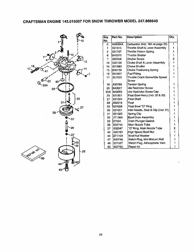
CRAFTSMAN ENGINE 143.015007 FOR SNOW THROWER MODEL 247.886640
II
31.1_
- 25
KeyNo.
01
2
67
1014
1516
17
18
2020A
2527
2829
3031
3233
3637
4044
4748
60
Part No. Description Qty,
i640084A631615
_31767
640070650506
632108631890
630735631807
651025
630766640027
640053
631951631024
632019631028
631021831022
27136A27554
632745132547
64018327110A
630748631027
632760
Carburetor (Incl. 184 on page 33)
Throttle Shaft & Lever Assembly
Throttle Return SpringThrottle Shutter
Shutter Screw
Choke Shaft & Lever AssemblyChoke Shutter
Choke PositioningSpring
Fuel FittingThrottle Crack Screw/Idle SpeedScrew
Tension SpringIdle Restrictor Screw
Idle Restrictor Screw CapFloatBowlAss'y (Incl. 32 & 33)Float ShaftFloat
Float Bowl "O" Ring
Inlet Needle, Seat & Clip (Incl. 31 )
SpringClipBowl Drain Assembly
Drain Plunger GasketMain Nozzle Tube
"O" Ring, Main Nozzle TubeHigh Speed Bowl NutBowlNut Washer
Welch Plug, Idle Mixture Well
Welch Plug, AtmosphericVent
Repair kit
11
1
12
11
11
1
1
111
1
11
11
11
12
11
11
1
29

CRAFTSMAN ENGINE 143.015007 FOR SNOW THROWER MODEL 247.886640
76
g_'150 60
/
2
287 390 3/70K
262
3O

CRAFTSMAN ENGINE 143.015007 FOR SNOW THROWER MODEL 247.886640
Key No. Part No.0
O
1 36469A
2 267274 0
5 3096914 28277
15 3133416 3,1510
,17 31335
18 65101819 31426
20 3260025 36552
26 65080230 35975
40 36073
40 3607440 36075
41 3607041 36071
41 36072
42 36076
42 3607742 36078
43 2038145 32875A
46 32610A48 27241
49 3265450 _36650
60 29745
64 3006364A 8345
65 65012869 27677A
70 34678A
75 2789776 30318
80 30574A81 30590A
82 3059,183 30588A
86 650488
89 6.1096190 6.11199
92 65081593 650816
160 34443B101 610118
102 651024
103 $51007
Description
RPM High 3450 to 3750RPM Low 1850 to 2150
Cylinder (Incl. 2,20,72 & 125)Dowel Pin
Oil Drain Exth. (Purchase Local)Extension CapWasher
Governor RodGovernor Lever
Governor Lever ClampScrew, Torx T- 15, 8-32 x 19/64"
Extension SpringOil Seal
Blower Housing Baffle (Incl. 262)Screw, 1/4-20 x 5/8"Crankshaft
Piston, Pin & Ring Set (Std.)Piston, Pin & Ring Set (.010" OS)
Piston, Pin & Ring Set (.020" OS)Piston & Pin Ass'y. (Std.) (Incl. 43)
Piston & Pin Ass'y. (.010" OS)(Incl. 43)Piston & Pin Ass'y. (.020" OS)(Incl. 43)Ring Set (Std.)
Ring Set (.010" OS)Ring Set (.020" OS)
Piston Pin Retaining RingConnect. Rod Ass'y. (Incl. 46, 49)
Connecting Rod BoltValve Lifter
Oil DipperCamshaft (BCR)
Btower Housing ExtensionScrew, Torx T-30, 1/4-20 x 1/2"Washer
Screw, 10-24 x 1/2"
Cylinder Cover Gasket
Cytinder Cover (Incl. 75 thin 83)Oil Seal
Camshaft Seal3overnor Shaft
Washer
Governor Gear Ass'y. (Incl. 81)
._overnorSpoolScrew, .1/4-20x ,1-1/4"
Flywheel KeyFlywheel (WIRing Gear)Belleville Washer
Flywheel Nut
Solid State IgnitionSpark Plug Cover
Solid State MountingStudScrew, Torx T-15, 10-24 x 15/16"
Qty.O
01
2
11
1
11
111
1
1
2
Key No. Part No.110 35182
110A 36874
119 36443
120 36441125 36471
125 36472126 32644A
126 32645A127 650691
130 602,1A
130A 650694A130B 650818135 35395
150 31672
151 3,16731 169 27234A
1 170 276661 171 11410
1 172 14146
1 173 353501 174 650783
176 297521 181 650870
182 62011 183 34583A
1 !84 267561 185 33691
2 186 32698
1 200 366772 203 313422 204 651029
1 206 6109731 209 650139
1 209A 30322
1 215 354401 219 34582
1 220 354381 222 28820
1 223 B506641 224 33673A
1 260 35656A1 262 650737
1 267 34212
1 268 302001 274 33670A
7 275 357711 277 650327
1 285 36467A,1 287 650926
1 290 307051 292 26460
1 298 650665
2 300 355842 301 35355
DescriptionGround Wire
Ground Wire
Cylinder Head Gasket
Cylinder Head (Incl. 131)ExhaustValve (Std.) (Incl. 151)Exhaust Val. (1/32" OS) (Incl. 151
Intake Valve (Std.) (Incl. 151)
Intake Valve (1/32" OS) (Incl. 151)Washer
Screw, 5/16-18 x 1-1/2"
Screw, 5/16-18 x 2"Screw, 5/16-18 x 1-1/2"
Resistor Spark Plug (RJ19LM)Valve Spring
Valve Spring CapValve Cover Gasket
Breather BodyBreather Element
Valve CoverBreather Tube
Screw, 10-24 x 3/4"
Nut & Lock Washer, 1/4-28"Screw, 1/4-28 x 1-11/16"
Screw, 1/4-26 x 7/8"Choke Bracket
Carburetor To Intake Pipe Gasket
Intake PipeGovernor Link
Control Bracket (Incl. 203-209A)CompressionSpring
Screw, Torx T-15, 5-40 x 7/16"terminal
Screw, 8-32 x 3/4"
Lock Nut, 8-32Control Knob
Choke RodChoke Knob
Screw, 10-32 x 1/2"
Screw, 1/4-20 x 1-19/32"
Intake Pipe GasketBtower HousingScrew, 1/4-20 x 1/2"Hold Down Bracket
Screw, !0-24 x 9/16"Exhaust Gasket
Muffler (Ind. 274)Screw, 1/4-20 x 2-27/64"
Starter CupScrew, 8-32 x 21/64"
Fuel Line
Fuel Line ClampScrew, 1/4-15 x 3/4"
Fuel Tank (Incl. 292 & 301)
Fuel Cap
Qty.1
1
11
11
1
11
2
511
2
22
11
11
22
,11
11
11
11
11
22
11
t2
21
1
21
1
11
21
21
42
1
1Table continued on next page
31

CRAFTSMAN ENGINE 143.015007 FOR SNOW THROWER MODEL 247.886640
Table continued from previous page:
Key No.3O53O7
308
310313
328329
335338
340345
35O
351355
364365
370A370B370C
370D370G
370K
38O390
3964OO
420
9OO
PaN No.
3555435499
35539
35556
3408035062610973
35072650257
36247
33344570682A
32180C590574
33333650735
362613528236501
3587836534
36695
640084A590742
33290E36444
730226
754303
DescriptionlOll FillTube
Oil FillTube "0" Ring
Oil FillTube ClipDipstickAss'y,
iSpacerIgnition KeyTerminal
Carburetor Cover
Screw, 8-32 x 5/16"Fuel Tank Bracket
Heat Baffle
Primer Ass'y.Primer Line
Starter Handle (Mitten Grip)Carburetor Cover Bracket
Screw, 10-24 x 3/8"Lubrication DecalInstructionDecalPrimer Decal
Warning DecalInstruction Decal
Starter Decal
Carburetor (Incl. 184)Rewind Starter
ElectricStarter
Qty.1
1
1
112
11
2!
11
11
11
11
11
11
1
11
Gasket Set (Incl. Items Marked PK 1in Notes)
SAE 5W30 4-Cycle Engine Oil 1(Quart)
Replacement Short Block, Order 1From 71-999
32
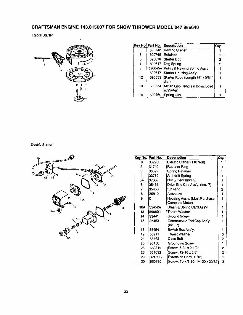
CRAFTSMAN ENGINE 143.015007 FOR SNOW THROWER MODEL 247.886640
Recoil Starter
m k-, 13
__, 14
Pad No.
590742590740
590616590617
590645A590647590535;
590574
590760'
Description Qty.Rewind Starter 1Retainer 1
Starter Dog 2
Dog Spring 2Pulley & Rewind Spring Ass'y 1
Starter Housing Ass'y tStarter Rope (Length 98" x 9/64" 1dia.)Mitten Grip Handle (Not included 1w/starter)Spring Clip 1
Electric Starter
16
25
24
18 15
Key No.02
345A
67
8
9
10A
1314
15
1619
2425
26
2629
30
PeN No.
33290E
,317493352213376937332
3546135450
35912
0
35452A
59050033441
35453
3545435911
3546235456
650819
65103232450B
650759
Description
Electric Starter (110 Volt)
Retainer RingSpring RetainerAnti-driftSpringNut & Gear (Incl. 2)
Drive End Cap Ass'y. (Incl. 7)"O" RingArmature
Housing Ass'y, (Must PurchaseComplete Motor)Brush & Spring Card Ass'y,Thrust WasherGround Screw
Commutator End Cap Ass'y,(Incl. 7)
Switch Box Ass'y.Thrust Washer
Case Bolt
Grounding ScrewScrew, 6-32 x 2-1/2"Screw, 12-16 x 5/8"
Extension Cord (10'6")Screw, Torx T-30, 1/4-20 x 23/32
_y.11
111
1
21
1
1
11
1
t
021
2
21
3
33