owner's manual snow thrower 247.888530 - …s manual 9 horse power 28" two-stage wheel...
TRANSCRIPT

Owner's Manual
9 Horse Power
28" Two-Stage Wheel Drive
Snow Thrower
Model No.
247.888530
CAUTION: Before
using this product,read this manual and
follow all safety rules
and operatinginstructions.
• Safety
• Assembly
• Operation• Service
• Maintenance
• EspaSol
Sears, Roebuck And Co., Hoffman Estates, IL 60179, U.S.A.
Visit our website: www.sears.com/craftsman FORM NO. 770-10057G
Prhted JnU.S.A. (8/2002)

Content Page
Warranty Information ......................................... 2
Safe Operation Practices ................................... 3
Assembly ........................................................... 6
Operation ........................................................... 12
Maintenance ...................................................... 17
Content Page
Service & Adjustment ......................................... 20
Off-Season Storage ........................................... 25
Trouble-Shooting ............................................... 26
Parts List ............................................................ 28
Espanbl .............................................................. 40
Two -Year Warranty on Craftsman Snow ThrowerFor two years from the date of purchase, when this Craftsman Snow Thrower is maintained, lubricated and tunedup according to the instructions in the owner's manual, Sears will repair, free of charge, any defect in materialand workmanship.
If this Craftsman snow thrower is used for commercial or rental purposes, this warranty applies for only 30 daysfrom the date of purchase.
This warranty does not cover:
Expendable items which become worn during normal use, such as skid shoes, shave plate and sparkplugs.
Repairs necessary because of operator abuse or negligence, including bent crankshafts and the failure tomaintain the equipment according to the instructions contained in the owner's manual.
WARRANTY SERVICE IS AVAILABLE BY RETURNING THE CRAFTSMAN SNOW THROWER TO THE NEARESTSEARS SERVICE CENTER!DEPARTMENT IN THE UNITED STATES.
This warranty applies only while this product is in use in the United States.
This warranty gives you specific legal rights and you may also have other rights which may vary from state to state.
SEARS, ROEBUCK AND CO., D/817WA, HOFFMAN ESTATES, IL60179
Horsepower: ......................... 9
Engine Oil ............................. SAE 5W30 oil
Fuel Capacity: ....................... 1 gallon
Spark Plug: ........................... RJ-19LM
Engine: .................................. 143.039001
Model Number 247.888530Serial Number ...........................................................
Date of Purchase ......................................................
Record both serial number and date of purchase andkeep in a safe place for future reference.

WARNING: This symbol points out important safety instructions which, if not followed, could endangerthe personal safety and/or property of yourself and others. Read and follow all instructions in this manualbefore attempting to operate this machine. Failure to comply with these instructions may result in personalinjury. When you see this symbol--heed its warning.
WARNING: Engine Exhaust, some of its constituents, and certain vehicle components containor emit chemicals known to State of California to cause cancer and birth defects or other
reproductive harm.
DANGER: This machine was built to be operated according to the rules for safe operation in this manual. As withany type of power equipment, carelessness or error on the pert of the operator can result in serious injury. This
machine is capable of amputating hands end feet and throwing objects. Failure to observe the following safetyinstructions could result in serious injury or death.
Training1. Read, understand, and follow all instructions on the
machine and in the manual(s) before attempting toassemble and operate. Keep this manual in a safe placefor future and regular reference and for orderingreplacement parts.
2. Be familiar with all controls and their operation. Knowhow to stop the machine and disengage controls.
3. Never allow children under 14 years old to operate thismachine. Children 14 years old and over should read andunderstand the operation instructions and safety rules inthis manual and should be trained and supervised by aparent.
4. Never allow adults to operate this machine withoutproper instruction.
5. Thrown objects can cause serious personal injury. Planyour snow-throwing pattern to avoid discharge of materialtoward roads, bystanders and the like.
6. Keep bystanders, helpers, pets and children at least 75feet from the machine while it is in operation. Stopmachine if anyone enters the area.
7. Exercise caution to avoid slipping or falling, especiallywhen operating in reverse.
Preparation1. Thoroughly inspect the area where the equipment is to
be used. Remove all doormats, newspapers, sleds,boards, wires and other foreign objects, which could betripped over or thrown by the auger/impeller.
2. Always wear safety glasses or eye shields duringoperation and while performing an adjustment or repair toprotect your eyes. Thrown objects which ricochet cancause serious injury to the eyes.
3. Do not operate without wearing adequate winter outergarments. Do not wear jewelry, long scarves or otherloose clothing, which could become entangled in movingparts. Wear footwear which will improve footing onslippery surfaces.
4. Use a grounded three-wire extension cord andreceptacle for all units with electric start engines.
5. Adjust collector housing height to clear gravel or crushedrock surfaces.
6. Disengage all clutch levers before starting the engine.7. Never attempt to make any adjustments while engine is
8,
9.
running, except where specifically recommended in theoperator's manual.Let engine and machine adjust to outdoor temperaturebefore starting to clear snow.To avoid personal injury or property damage use extremecare in handling gasoline. Gasoline is extremelyflammable and the vapors are explosive. Seriouspersonal injury can occur when gasoline is spilled onyourself or your clothes, which can ignite. Wash your skinand change clothes immediately.
a. Use only an approved gasoline container.b. Extinguish all cigarettes, cigars, pipes and other
sources of ignition.c. Never fuel machine indoors.
d. Never remove gas cap or add fuel while theengine is hot or running.
e. Allow engine to cool at least two minutes beforerefueling.
f. Never over fill fuel tank. Fill tank to no more than
Y2inch below bottom of filler neck to provide spacefor fuel expansion.
g. Replace gasoline cap and tighten securely.h. If gasoline is spilled, wipe it off the engine and
equipment. Move machine to another area. Wait 5minutes before starting the engine.
L Never store the machine or fuel container inside
where there is an open flame, spark or pilot light(e.g. furnace, water heater, space heater, clothesdryer etc.).
j. Allow unit to cool for 5 minutes before storing.
Operation1 DOnot put hands or feet near rotating parts, in the auger/
impeller housing or discharge chute. Contact with therotating parts can amputate hands and feet.
2. The auger/impeller clutch lever is a safety device. Neverbypass its operation. Doing so makes the machineunsafe and may cause personal injury.
3. The clutch levers must operate easily in both directionsand automatically return to the disengaged position whenreleased.
4. Never operate with a missing or damaged dischargechute. Keep all safety devices in place and working.
5. Never run an engine indoorsor in a poorly ventilated

area.Engineexhaustcontainscarbonmonoxide,anodorlessanddeadlygas.
6. Donotoperatemachinewhileundertheinfluenceofalcoholordrugs.
7. Mufflerandenginebecomehotandcancauseaburn.Donottouch.
8. Exerciseextremecautionwhenoperatingonorcrossinggravelsurfaces.Stayalertforhiddenhazardsortraffic.
9. Exercisecautionwhenchangingdirectionandwhileoperatingonslopes.
10.Planyoursnow-throwingpatterntoavoiddischargetowardswindows,walls,carsetc.Thus,avoidingpossiblepropertydamageorpersonalinjurycausedbyaricochet.
11.Neverdirectdischargeatchildren,bystandersandpetsorallowanyoneinfrontofthemachine.
12.Donotoverloadmachinecapacitybyattemptingtoclearsnowattoofastofarate.
13.Neveroperatethismachinewithoutgoodvisibilityorlight.Alwaysbesureofyourfootingandkeepafirmholdonthehandles.Walk,neverrun.
14.Disengagepowertotheauger/impellerwhentransportingornotinuse.
15.Neveroperatemachineathightransportspeedsonslipperysurfaces.Lookdownandbehindandusecarewheninreverse.
16.Ifthemachineshouldstarttovibrateabnormally,stoptheengine,disconnectthesparkplugwireandgrounditagainsttheengine. Inspect thoroughly for damage.Repair any damage before starting and operating.
17. Disengage all clutch levers and stop engine before youleave the operating position (behind the handles). Waituntil the augedimpeller comes to a complete stop beforeunclogging the discharge chute, making anyadjustments, or inspections.
18. Never put your hand in the discharge or collectoropenings. Always use the clean-out tool provided tounclog the discharge opening. Do not unclog dischargechute while engine is running. Before unclogging, shut offengine and remain behind handles until all moving partshave stopped completely.
19. Use only attachments and accessories approved bythemanufacturer (e.g. wheel weights, tire chains, cabs etc.).
20. If situations occur which are not covered in this manual,use care and good judgment. Contact Sears servicecenter for assistance.
Maintenance & Storage1 Never tamper with safety devices. Check their proper
operation regularly. Refer to the maintenance andadjustment sections of this manual.
2. Before cleaning, repairing, or inspecting machinedisengage all clutch levers and stop engine. Wait until theauger/impeller come to a complete stop. Disconnect thespark plug wire and ground against the engine to preventunintended starting.
3. Check bolts and screws for proper tightness at frequentintervals to keep the machine in safe working condition.Also, visually inspect machine for any damage.
4. Do not change the engine governor setting or over-speedthe engine. The governor controls the maximum safeoperating speed of the engine.
5. Snow thrower shave plates and skid shoes are subject towear and damage. For your safety protection, frequentlycheck all components and replace with originalequipment manufacturer's (OEM) parts only. "Use ofparts which do not meet the original equipmentspecifications may lead to improper performance andcompromise safety!"
6. Check clutch controls periodically to verify they engageand disengage properly and adjust, if necessary. Refer tothe adjustment section in this operator's manual forinstructions.
7. Maintain/replace safety/instruction labels, as necessary.8. Observe proper disposal laws and regulations for gas,
oil, etc. to protect the environment.9. Prior to storing, run machine a few minutes to clear snow
from machine and prevent freeze up of auger/impeller.10. Never store the machine or fuel container inside where
there is an open flame, spark or pilot light such as a waterheater, furnace, clothes dryer etc.
11. Always refer to the operator's manual for properinstructions on off-season storage.
Your ResponsibilityRestrict the use of this power machine to persons whoread, understand and follow the warnings andinstructions in this manual and on the machine. The
safety labels are shown below for your reference.

Laythehardwarepiecesfromthehardwarepackonthefigurehereandyouwillhaveautomaticallysortedtheseaccordingtothestepsoftheassemblyproceduredescribedlater. (Only one unit of each hardware has been shown per group.The number in parenthesis indicates the total number of the hardware needed in that group.)
A
B
Hex Bolt (2)
_ ,,,.
__ 5/16-18 x 1.75
Hex Bolt (2)
5116-18 X .75
Lock Washer (4)
,©HandleTab (2)
/
C
/HairpinClip (1)
Hairpin Clip (2)
Flat
Washer (2) c
5/16 C) Ferrule(t)
D: Spare Parts
HexNut (2)**Lock
'--- Shear Bolt (2)* Nut (2)* _'_--_'_
* Used on auger; ** used on clutch lever
Hex Bolt_ (6) /_ /NutFlanged(6)
- 1/4-20 x .75 114-20
I
Chute Flange Keeper (3)
Hairpin Clip (1) Flat
"_ __asher(2)
3/8
m
G -
_/ Cable Tie (2)

/Discharge Chute
Handle & HandlePanel Assembly _,
Right
Front
Rear
\Chute
Crank
Figure 1
IMPORTANT: This unit is shipped with engine oil in theengine, but without gasoline. After assembly, seeOPERATION section of this manual for fuel selection
and fill-up.
Removing From Carton• Cut the corners of the carton and lay the sides flat
on the ground. Remove all packing inserts.• Remove all loose parts. For a complete list of the
loose parts, refer to the following section.• Move the snow thrower out of the carton.
• Make certain all parts and literature have beenremoved before discarding the carton.
Loose PartsYour snow thrower has been assembled at the factory
except the parts shipped loose in the carton. These arelisted below.
(See Figure 1 .)a. Handle and Handle Panel Assemblyb. Chute Assemblyc. Electric Start Cord
d. Two-piece Chute Crank Assemblye. Shift Rod
f. Hardware Pack
ShiftRod
ElectricStart Cord
Tools Required1. 1/2", 7/16", 3/8" wrenches or a set of adjustable
wrenches
2. Set of pliers3. Set of philips head screw drivers
4. Funnel to fill up gasoline
Before Assembly• Disconnect spark plug wire and ground it against
the engine to prevent unintended starting.
NOTE: All references in this manual to the left or rightside of the snow thrower is from the operating position
only. Exceptions, if any, will be specified.
Attaching Handle Assembly• Stretch out the control cables and place the
handles and handle panel assembly on the floor.See Figure 2.
• Position the two ends of the handles on the snow
thrower frame as indicated by arrows in Figure 2.
For your convenience, you may place thedischarge chute on the chute opening. Align thetwo lower holes on each handle to the
corresponding holes on the snow thrower frame.
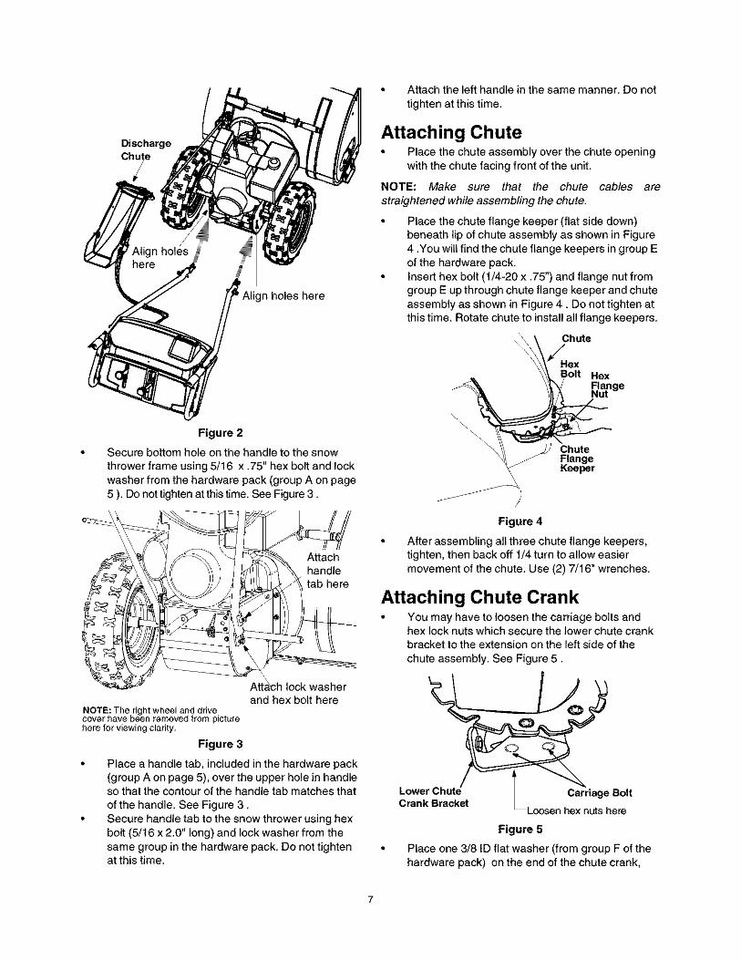
Discharge
n holes here
Figure 2
Secure bottom hole on the handle to the snow
thrower frame using 5/16 x .75" hex bolt and lock
washer from the hardware pack (group A on page5 ). Do not tighten at this time. See Figure 3.
Attachhandletab here
Atta_ch lock washer
and hex bolt hereNOTE: The right wheel and drivecover have been removed from picturehere for viewing clarity,
Figure 3
• Place a handle tab, included in the hardware pack(group A on page 5), over the upper hole in handleso that the contour of the handle tab matches that
of the handle. See Figure 3.• Secure handle tab to the snow thrower using hex
bolt (5/16 x 2.0" long) and lock washer from thesame group in the hardware pack. Do not tightenat this time.
• Attach the left handle in the same manner. Do not
tighten at this time.
Attaching Chute• Place the chute assembly over the chute opening
with the chute facing front of the unit.
NOTE: Make sure that the chute cables are
straightened while assembling the chute.
• Place the chute flange keeper (flat side down)beneath lip of chute assembly as shown in Figure
4 .You will find the chute flange keepers in group Eof the hardware pack.
• Insert hex bolt (1/4-20 x .75") and flange nut fromgroup E up through chute flange keeper and chute
assembly as shown in Figure 4. Do not tighten atthis time. Rotate chute to install all flange keepers.
Chute/
HexBolt Hex
Range
\ChuteFlange
\ Keeper\
Figure 4
After assembling all three chute flange keepers,tighten, then back off 1/4 turn to allow easier
movement of the chute. Use (2) 7/16" wrenches.
Attaching Chute Crank• You may have to loosen the carriage bolts and
hex lock nuts which secure the lower chute crankbracket to the extension on the left side of the
chute assembly. See Figure 5.
Lwr h _
Figure 5
• Place one 3/8 ID flat washer (from group F of thehardware pack) on the end of the chute crank,

theninserttheendofthechutecrankintotheeyeholeintheplasticbushinginthelowerchutecrankbracket.SeeFigure6.
Hairpin CI Plastic Bushing
Chute Crank
Slip the cables that run from the handle panel to thechute into the cable guide located on top of the
engine. See Figure 8.
Cable CableGuide
Lower ChuteCrank Bracket Flat Washer
Figure 6
• Place the other 3/8 ID flat washer (from the samegroup of hardware) on the end of the chute crank
and insert hairpin clip into hole at the end of thechute crank. See Figure 6.
• Adjust the chute bracket so that the spiral on thechute crank fully engages the teeth on the chute
assembly. Tighten hardware (Figure 6) on thelower chute crank bracket, if loosened earlier.
• Slide the upper chute crank through the plastic
bushing in the upper chute crank bracket and theninto the lower chute crank. See Figure 7. Align the
holes on the two pieces of the chute crank, andsecure with hairpin clip from group B of thehardware pack.
UpperChuteCrank
UpperChuteCrankBracket
Crank
Figure 7
Fully rotate the chute, using the chute crank, tomake sure that it moves freely.
Using a wrench, tighten the hex bolt and the hexnut on the upper chute crank bracket.
Figure 8
• Tighten all loose hardware on the handle assembly
nOW.
Attaching Clutch CablesThe clutch control cables are attached to the snow
thrower. For shipping purposes, if the cables areattached to the top of the engine with cable ties, cut thecable ties now. The Z ends of the clutch cables are
hooked into the clutch grips on each handle.• Ensure there is a hex jam nut threaded all the way
up the threaded portion of the Z fitting; extras aresupplied in the hardware pack. See Figure 9.
• Place the clutch grip in the raised (up) position.
Outerof cut-out
\
Hex JamNut
Nut
:LFerrule
(Viewedfromthe undersideof thehandlepanel)
Figure 9
Swing the left auger cable up making sure the cableis routed correctly in the cable roller guides locatedat the lower rear of the unit.Hold the end of the cable at the barrel so the ferrule
turns freely without twisting the cable. Thread theferrule on to the Z fitting. You may have to pull onthe cable slightly to relieve tension. Keep the
ferrule turning without twisting the cable.

• Youwillreachcorrectadjustmentwhenthereisminimalslackinthecablebutitisnottight.Holdtheflatsontheferrulewithpliersandtightenthejamnutagainsttheferrule.
CAUTION:Cableswillbecomelooseifyoudonottightenthejamnut.
WARNING: There must not be any tension
on either clutch cable with the drive or augerclutch grip in the disengaged (up) position.
These clutches are a safety feature. Do notoverride their function.
Attaching Shift Rod• Place the shift lever in the sixth (6) speed.• Place the bent end of the shift rod into the hole in the
shift arm assembly. See Figure 10. Secure with 5/16flat washer and hairpin clip from group D of thehardware pack.
• Thread ferrule (included in group C) from the rightside onto the other end of the shift rod till it lines up
with the upper hole in the shift lever (beneath thehandle panel). While aligning the ferrule, push
down on the shift rod and the shift arm assemblyas far as it will go.
NOTE: You may have to pull the shift lever out of thesixth speed position and move it towards the fifth speed
position until the ferrule slides into the hole withoutforce.
Once the ferrule slides into the hole, turn itcounter-clockwise one more full turn and insert it
in the hole in the shift lever. For proper positioningof the ferrule and the associated hardware, see
Figure 10.ShiftLever Chute Distance
Control
TractionDrive
ClutchClip
Washer
HairpinClip
FinWasher
Shift ArmAssembly
Figure 10
• Secure the ferrule to the shift lever with another 5/
16 flat washer and hairpin clip from group C of the
hardware pack. See Figure 10.• Check for correct adjustment of the shift rod, as
instructed in the Adjustment section, beforeoperating the snow thrower.
Attaching Turn Triggers• Check and make sure that the right hand trigger
cable is routed in front of the traction drive cable.
• Feed the trigger cable up through the outer side of
the slot in the handle panel. Do not feed the cablethrough the same side of the slot as the Z fitting.
• Place the cable barrel fitting into the hole in thetrigger. You can find the triggers and associated
hardware in group H of the hardware pack. SeeFigu re 11.
Trigger
Inner Cabl[_sem_
/Barrel SlotFitting Cable snaps in at
this end
Figure 11
• Pull on the cable and rotate it around the bottom of
the trigger, with the inner cable in the slot, until the
cable end can be pushed into the trigger housingand snapped tight. See Figure 11 .
NOTE: When the cable is installed correctly, you
should not be able to pull the cable out of the triggerhousing.
Place the right turn trigger in position underneath
the right handle. Insert screw, from group G of thehardware pack, into the hole on the handle and theweld nut molded on the turn trigger assembly. See
Figure 5. Tighten screw with a Philips screw driver.Repeat on the left side.
/I I "_ _ TurnSlot" _ ,_.,....._......_ _Trigger
Figure 12

Secure the right turn trigger cable to the right lowerhandle using cable tie provided in the hardware
pack. Make sure not to wrap the drive cable. SeeFigure 13.
Tie\_ Trigger CableCable
Figure 13
Secure the left turn trigger cable to the Iower handleusing the other cable tie. Make sure to route the
cable tie below the auger drive cable so that whenthe trigger cable is secured by the cable tie, theauger drive cable is left outside the cable tie. Trimexcess ends from each cable tie.
NOTE: The right side cable tie must be used to keepcable from coming in contact with the moving shift armfrom the transmission.
Lamp Wiring• Wrap the wire from the lamp down the right handle
as shown in Figure 15.
• Plug wire into the alternator lead wire under the fueltank. See Figure 14.
Final Adjustments
Auger Control• To check the adjustment of the auger control, push
forward the left hand clutch grip until the rubber
bumper is compressed. There should be slack inthe clutch cable.
• Release the clutch grip. The cable should bestraight. Make certain you can depress the augercontrol grip against the left handle completely.
• If adjustment is necessary, loosen the hex jam nut
and thread the cable in (for less slack) or out (formore slack). See Figure 15.
• Recheck the adjustment. Tighten the jam nutagainst the cable when correct adjustment isreached.
AugerControl_
Z-End j
Jam Nut j
Auger
Alternator Lead
NOTE: Wheetsare omittedfrom illustrationforclarity.
Figure 14
IMPORTANT: Assemble your snow thrower, then checkthe adjustments as instructed and make any finaladjustments necessary before operating the unit.
Failure to follow these instructions may cause damageto the snow thrower.
Chute Clean-Out Tool• This tool is fastened with a cable tie to the rear of
the auger housing for shipping purposes. Cut thecable tie and remove the tool before operating thesnow thrower.
Figure 15
Traction Drive Clutch and Shift Lever• Tip the snow thrower forward so that it rests on the
auger housing.• Move the shift lever all the way forward to the sixth
(6) position.
• With the traction drive lever released, spin the snowthrower wheels by hand. The wheels should turn;
however, you may feel some resistance.• Engage the traction drive clutch grip. The wheels
should no longer turn.• Now release the traction drive clutch grip, and spin
the wheels again.• Move the shift lever back to the fast reverse
position, then all the way forward again. Thereshould be no resistance in the shift lever, and thewheels should turn.
10

• Ifyoufaceresistancewhenmovingtheshiftleverorthesnowthrowerwheelsstopwhentheyshouldnot,loosenthelocknutonthetractiondrivecableandunthreadthecableoneturn.
• Ifthewheelscanstillbeturnedwhenyouengagethetractiondriveclutchgrip,loosenthelocknutonthetractiondrivecableandthreadthecableinoneturn.
• Rechecktheadjustmentandrepeatadjustmentasnecessary.Tightenthejamnuttosecurethecablewhencorrectadjustmentisreached.
NOTE:If you are not sure that you have reachedcorrect adjustment, refer to the Adjustment section on
page 20.
Skid Shoe
The space between the shave plate end the ground
can be adjusted. For close snow removal, place skidshoes in the low position. Use middle or high positionwhen area to be cleared is uneven.
NOTE: It is not recommended that you operate thissnow thrower on gravel as loose gravel can be easilypicked up and thrown by the auger causing an injury ordamage to the snow thrower.
• If for some reason, you have to operate the snowthrower on gravel, keep the skid shoe in the highest
position for maximum clearance between theground and the shave plate.
• Adjust skid shoes by loosening the four hex nutsand carriage bolts and moving skid shoes to
desired position.• Make certain the entire bottom surface of skid shoe
is against the ground to avoid uneven wear on theskid shoes.
• Tighten nuts and bolts securely.
_Skid Shoe
Loosen these hardware
to adjust skid shoeFigure 16
Tire Pressure (Pneumatic Tires)The tires ere over-inflated for shipping purposes.
Check tire pressure and reduce to 15 to 20 psi.
NOTE: If the tire pressure is not equal in both tires, theunit may pull to one side or the other.
11

Knowing Your Snow ThrowerRead this owner's manual and safety rules before operating your snow thrower. Compare illustration below with
your snow thrower to familiarize yourself with the location of various controls and adjustments. Save this manual forfuture reference.
Traction Shift Lever
Auger Control Lock jr/erContml
Chute Crank
DischargeChute
Chute "_
Clean-Out
Aug6rSkid Shoe
Oil
Spark FillPlug
Choke
Electric
Starter _Ignition JKey
Primer j
Throttle J
Fuel
Fuel
_TankStarterHandle
RecoilStarter
Figure 17
Operating Controls(See Figure 17 .)
Traction Control / Auger Control Lock
The traction control is located on the right handle.Squeeze the traction control to engage the wheel drive.
Release to stop.
This same lever also locks the auger control so you canoperate the chute crank without interrupting the snow
throwing process. If the auger control is engagedsimultaneously with the traction control, the operatorcan release the auger control (on the left handle) and
the augers will remain engaged. Release the tractioncontrol to stop the augers and wheel drive (the augercontrol must also be released).
IMPORTANT: Always release the traction control beforechanging speeds.
Auger ControlThe auger control is located on theleft handle. Squeeze the augercontrol to engage the augers.
Release to stop the snow throwingaction. The traction control must also
be released in order to stop auger.
HeadlightThe headlight is on whenever the engine is running.
Throttle Control
The throttlecontrolis located on the engine. It regulatesthe speed ofthe engine.
Safety Ignition KeyThe safety ignition key must be fully inserted in theswitch before the unit will start. Remove key when snow
thrower is not in use. Do not attempt to turn the key.
Meets ANSI Safety StandardsSears snow throwers conform to the safety standards B71.3 of the American National Standards Institute (ANSI).
12

Shift Lever
The shift lever is located in the center
of the handle panel and is used to
determine ground speed anddirection of travel. It can be moved
into any of eight positions.
IMPORTANT: Always release tractionthe control before changing speeds.
Forward: The snow thrower has six
forward (F) speeds. Position one (1)is the slowest and position six (6) isthe fastest.
Reverse: The snow thrower has two
reverse (R) speeds--R1 is the slowerof the two.
6 m
5--
4--
3--
2--
1--
R1--
R2--
Discharge ChuteThe angle of the discharge chute controls the distancethat the snow is thrown. Tilt the discharge chute up forgreater distance; tilt down for less distance.
Chute CrankThe chute crank is located on the lefthand side of the snow thrower. Use it
to change the direction in which snowis thrown. Avoid targetting persons,animals or cars and buildings.
CLOCKWISE TODISCHARGE LEFT
COUNTIER CLOCKWISE
TO DISCHARGE RIGHT
Chute Distance ControlThe distance snow is thrown can be
changed by adjusting the angle of thechute assembly. Move the chutedistance control forward to decrease
the distance and toward the rear toincrease the distance.
Chute Clean-Out Tool
The chute clean-out tool is designed to clear a cloggeddischarge chute. Refer to page 16 for instructions onhow to properly use it.
WARNING: Never use your hand to clear aclogged discharge chute. Shut off engine andremain behind handles until all moving partshave stopped before unclogging.
Wheel Steering ControlsThe left and right wheel steeringcontrols are located on the undersideof the handles.
• Squeeze the right control to turn right; squeeze theleft control to turn left.
NOTE: Operate the snow thrower in open areas untilyou are familiar with these controls.
Skid Shoe
The skid shoe position is determined by the condition ofthe ground from where snow has to be removed. Higher
the snow level, lower will be the skid shoe. Adjust itaccordingly.
Stopping Snow Thrower• To stop the wheels, release the traction drive lever
of the snow thrower.
• To stop throwing snow, release the auger drive lever.• To stop the engine, push throttle control lever to
OFF and pull out the ignition key. Do not turn key.
Before Starting Engine
Fill Gas
WARNING: Gasoline is flammable; usecaution when handling or storing it.
Do not fill fuel tank while the snow thrower is
running, when it is hot or when it is in anenclosed area.
Keep your snow thrower away from any openflame or an electrical spark and do not smokewhile filling the fuel tank.
Never fill the fuel tank completely. Fill the tankto within 1/4"-1/2" from the top to provide spacefor expansion of fuel.
Always fill the fuel tank outdoors and use a
funnel or spout to prevent spilling.
Make sure to wipe off any spilled fuel beforestarting the engine.
• Store gasoline in a clean, approved container and
keep the cap in place on the container.• Make sure that the container from which you pour
the gasoline is clean and free from rust or otherforeign particles.
• A plastic cap is provided inside the fuel fill opening
on the fuel tank. Remove and discard this capbefore filling up the tank. Use the separate fuel tank
cap to close after fill-up.• Fill fuel tank with clean, fresh, unleaded grade
automotive gasoline.• At the end of the job, empty the fuel tank if the snow
thrower is not going to be used for 30 days orlonger. See storage instructions on 25 of thismanual.
CAUTION: Experience indicates that alcohol blended
fuels (called gasohol) or those using ethanol ormethanol can attract moisture which leads to
separation and formation of acids during storage.
Acidic gas can damage the fuel system of an
13

enginewhileinstorage.Toavoidengineproblems,thefuelsystemshouldbeemptiedbeforestoragefor30daysorlonger.Drainthegastank,starttheengineandletitrununtilthefuellinesandcarburetorareempty.Usefreshfuelnextseason.SeestorageInstructionsforadditionalinformation.Neveruseengineorcarburetorcleanerproductsinthefueltankorpermanentdamagemayoccur.
Fill Oil
The engine was shipped with oil in the engine. Checkthe levell of oil before each operation and make sure
there is adequate oil in the engine. Refer to instructionson page 18 for correct procedure.
To Start EngineWARNING: Be sure no one other than the
operator is standing near the snow thrower
while starting or operating. Do not operate thissnow thrower unless the discharge chuteassembly has been properly installed and issecured.
Electric Starter
For location of all the engine controls referred to in thissection, see Figure 17 inset. For illustration of starting
instructions, see Figure 18.
Before starting, make sure that the engine has suffi-cient oil. The snow thrower engine is equipped with a120 volt A.C. electric starter and recoil starter. The
electric starter is equipped with a three-wire powercord and plug and is designed to operate on 120 volt
AC household current. Follow all instructions carefully.
Cold Start
NOTE: If the unit shows any sign of motion (drive oraugers) with the clutch grips disengaged, shut theengine off immediately. Readjust as instructed in the"Final Adjustments" section of the AssemblyInstructions.
WARNING: The electric starter must be
properly grounded at all times to avoid thepossibility of electric shock which may beinjurious to the operator.
• Determine whether your house wiring is a three-wire grounded system. Ask a licensed electrician ifyou are not certain.
_ ARNING: If your house wiring system is nota three-wire grounded system, do not use thiselectric starter under any conditions.
• If your house wiring system is grounded and athree-hole receptacle is not available at the point
the snow thrower starter will normally be used, oneshould be installed by a licensed electrician.
• When connecting the power cord, always connectcord to starter on engine first, then plug the other
end into a three-hole grounded receptacle.• When disconnecting the power cord, always
unplug the end from the three-hole, grounded
receptacle first.• Attach spark plug wire to spark plug.• Make sure that the auger drive and the traction
drive levers are in the disengaged position.
Connect sparkplug wire
Move
Pushbu_on
Pull starter ifusing RecoilStarterprocedure
Figure 18
• Move throttle control lever to FAST position.• Remove the keys from the plastic bag. Push key
into the ignition slot. Make sure it snaps into place.Do not turn key.
• Rotate the choke knob to FULL choke position.• Connect the power cord to the switch box on the
engine.• Plug the other end of the power cord into a three-
hole, grounded 120 volt A.C. receptacle.
,_ WARNING: Do not use primer while startingthe engine with an electric starter.
• Push down on the starter button until the enginestarts. Do not crank for more than 10 seconds at a
time. This electric starter is thermally protected. Ifoverheated, it will stop automatically and can berestarted only when it has cooled to a safe
temperature (a wait of about 5 to 10 minutes isrequired).
• When the engine starts, release the starter buttonand slowly rotate the choke to OFF position. If theengine falters, rotate the choke to FULL and then
gradually to OFF.
14

Disconnectthepowercordfromthereceptaclefirstandthenfromtheswitchboxontheengine.Allowtheenginetowarmupforafewminutesbecausetheenginewillnotdevelopfullpoweruntilit reachesoperatingtemperature.Operatetheengineatfullthrottle(FAST)whenthrowingsnow.
Warm Start
• If restarting a warm engine, rotate choke to OFF
instead of FULL and press the starter button.
Recoil Starter
Make sure that the engine has sufficient oil and theauger drive and the traction drive levers are released.
• Move throttle control to FAST position.• Push key into the ignition slot so that it snaps into
place. Do not turn key.• Rotate choke control to FULL choke position.• Push the primer button while covering the vent hole.
Remove your finger from the primer between primes.
Do not prime if temperature is above 50° F; prime
two times between 50° F and 15° F; and prime fourtimes below 15' F.
• Pull the starter handle rapidly. Do not allow thehandle to snap back, but allow it to rewind slowly
while keeping a firm hold on the starter handle.• As the engine warms up and begins to operate
evenly, rotate the choke knob slowly to OFFposition. If the engine falters, return to FULL choke,
then slowly move to OFF choke position.• Allow the engine to warm up for a few minutes
because the engine will not develop full power until
it reaches operating temperature.• Operate the engine at full throttle (FAST) when
throwing snow.
Warm Start
• If restarting a warm engine after a temporary shutdown, rotate choke to OFF instead of FULL and do
not prime. Press the starter button.
Frozen Recoil Starter
If the starter is frozen and will not turn the engine, pro-ceed as follows:
• Pull as much rope out of the starter as possible.• Release the starter handle and let it snap back
against the starter.• If the engine still fails to start, repeat the first two
steps. If continued attempts do not free starter,follow the electric starter procedures to start.
• Avoid possible freezing of recoil starter and the
engine controls.
To Engage Drive• With the engine running near top speed, move shift
lever to one of six FORWARD positions or twoREVERSE positions. Select a speed appropriate
for the snow conditions that exist. Use slower
speeds until you are familiar with the operation ofthe snow thrower.
Squeeze the traction drive clutch grip against the
right handle and the snow thrower will move.Release it and the drive motion will stop.
To Engage Augers• To engage the augers and start snow throwing,
squeeze the left hand auger clutch grip against theleft handle. Release to stop augers.
• While the auger control is engaged, squeeze thetraction drive control to move, release to stop. Do
not shift speeds while the drive is engaged.
NOTE: This same lever also locks the auger control soyou can turn the chute crank without interrupting the
snow throwing process.
• Release the auger control; the interlock mechanismshould keep the auger control engaged until thetraction drive control is released.
• Release the traction drive control to stop both theaugers and the wheel drive.
,_ WARNING: To stop the auger, both leversmust be released
To Throw Snow
CAUTION: Check the area to be cleared for foreignobjects. Remove, ifany.
• Start the engine following starting instructions.• Rotate the discharge chute to the desired direction,
away from bystanders and/or buildings. Move thechute distance control forward or backward to
adjust the distance the snow is to be thrown.• Select the speed according to snow condition.
CAUTION: Never movethe shift lever without first
releasing the drive clutch.
• Engage the auger control and traction drive control
levers following instructions above.• The interlock feature will allow you to remove your
left hand from the auger control lever.• When clearing the first pass through the snow,
control the traction speed of the snow throweraccording to the depth and condition of snow.
• To turn the unit left, squeeze left trigger; to turnright, squeeze right trigger.
• On each succeeding pass, readjust the chute
deflector to the desired position and slightly overlapthe previously cleared path.
• After the area is cleared, stop the snow thrower
following instructions given below.
15

Operating Tips
NOTE: Allow the engine to warm up for a few minutesas the engine will not develop full power until it reaches
operating temperature.
_Chute Clean-Out Tool
/Clip
,_ WARNING: The temperature of muffler andsurrounding areas may exceed 150 ° F. Avoidthese areas.
• For most efficient snow removal, remove snow
immediately after it falls.• Discharge snow downwind whenever possible.
Slightly overlap each previous swath.• Set the skid shoes 1/4" below the scraper bar for
normal usage. The skid shoes may be adjustedupward for hard-packed snow.
NOTE: It is not recommended that you operate thissnow thrower on gravel as loose gravel can be easilypicked up and thrown by the auger causing an injury ordamage to the snow thrower.
• If for some reason, you have to operate the snow
thrower on gravel, keep the skid shoe in the highestposition for maximum clearance between the
ground and the shave plate.• Clean the snow thrower thoroughly after each use.
Chute Clean-Out ToolThe chute clean-out tool is conveniently fastened to therear of the auger housing with a mounting clip. Never
use your hand to clean a clogged chute.
• Release both the auger control lever and thetraction/auger control lock lever.
• Stop the engine by removing the ignition key.• Remove the clean-out tool from the clip which
secures it to the rear of the auger housing. SeeFigure 19.
• Use the shovel-shaped end of the clean-out tool to
remove any snow and ice in the discharge chute.• Re-fasten the clean-out tool to the mounting clip on
the rear of the auger housing and restart engine.
• While standing in the operator's position (behindthe snow thrower), engage the auger clutch lever
for a few seconds to clear any remaining snow orice from the discharge chute before continuing toclear snow.
Figure 19
Before Stopping• Run engine for a few minutes to help dry off any
moisture on engine.
• To avoidpossible freeze-up of the starter, followthese steps:
Recoil Starter
a. With the engine running, pull the starter ropewith a rapid, continuous full arm stroke threeor four times.
Electric Starter
a. Connect power cord to switch box, then to120 Volt AC receptacle.
b. While the engine is running, push the starterbutton and spin the starter for severalseconds.
c. Disconnect power cord from the receptacle
first, then from the snow thrower.
NOTE: The unusual sound from pulling the starter ropein the case of the recoil starter, or from spinning thestarter in the case of the electric starter, will not harmthe engine.
To Stop The Snow Thrower• To stop the wheel, release the traction drive lever
on the snow thrower.
• To stop throwing snow, release auger drive lever.• To stop engine, push throttle control lever to OFF
and pull out the key. Do nottum key.
Snow Spark DriveThrower Plugwire Levers
Electric Connect ReleaseStarter
Recoil Connect ReleaseStarter
Thro_lecontrol
Move toFAST
Move toFAST
Starting Instructions At A Glance
ignitionKey
Push to
snap in
Push tosnap in
Shake Power PrimerCord
Move to Connect --FULL [o source
Move to -- PrimeFULL
Starter
Pushbutton
Pullhandle
After starting
1. Release button2. Move Choke to Off3. Disconnect cord
1. Release handle2. Move Choke to Off.
16

General Recommendations• Always observe safety rules when performing any
maintenance.
• The warranty on this snow thrower does not cover
items that have been subjected to operator abuseor negligence. To receive full value from the
warranty, operator must maintain the snow throweras instructed in this manual.
• Some adjustments will have to be madeperiodically to maintain your unit properly.
• All adjustments in the Service and Adjustmentssection of this manual should be checked at least
once each season.
• Follow the maintenance schedule given below.
• Periodically check all fasteners and make surethese are tight.
,_ WARNING: Always stop the engine anddisconnect the spark plug wire beforeperforming any maintenance or adjustments.
Lubrication
IMPORTANT: Avoid spillage of oil on rubber frictionwheel and aluminum drive plate.
Auger Shaft• At least once a season, remove the shear bolts
from the auger shaft and spray lubricant inside theshaft. See Figure 21.
Vent Plu
Bolts
Figure 21
Auger Bearings and Shaft• Every season lubricate the auger bearings and the
bearings on the side of the frame with light oil. Seeto Figure 21.
Discharge Chute• The base of the discharge chute and the spirals on
the chute crank should be lubricated at least every
25 hours of use. Apply the lubricant under the baseof the chute and where the spirals contact the
discharge chute. See Figure 22.
Notes: For more details on thelube points, check the nextfour figures,
Figure 20: Lubrication Chart
Drive and Shifting Mechanism
• At least once a season or after every 25 hours ofoperation, remove rear cover. Lubricate any chains,
sprockets, gears, bearings, shafts, and the shiftingmechanism at least once a season. Use engine oilor a spray lubricant.
Lube under f
chute base
Figure 22
Chute CrankSpirals
17

Wheels
• Oil or spray lubricant into bearings at wheels at
least once a season. Pull klick pin, remove wheels,clean and coat axles with a multipurpose
automotive grease. See Figure 23.
_ .,____Klick Pin
Figure 23
Traction Control / Auger Control LockThe cams on the ends of the control rods which
interlock the traction drive and auger drive clutchesmust be lubricated at least once a season or every 25hours of operation using a multi-purpose automotive
grease. The cams can be accessed beneath the handlepanel. See Figure 24.
anel
Control Rods _ube Cams Here
Figure 24
Gear Shaft• Lubricate the gear shaft with 6-in-1 grease (part
number 737-0170) at least once a season, or after
every 25 hours of operation.
IMPORTANT: Keep all grease and oil off the rubber
friction wheel and drive plate.
Gear Case
The gear case is lubricated with grease at the factoryand does not require further lubrication regularly.
• However, if disassembled for any reason, lubricate
with 2 ounces of Shell AIvania TM grease EPR00,
part number 737-0168. Before reassembling,
remove old sealant and apply new sealant.
IMPORTANT: Do not overfill the gear case, sincedamage to the seals could result. Be sure the vent plugis free of grease in order to relieve pressure.
Check V-BeltsFollow instrcutions below to check the condition of the
drive belts every 50 hours of operation.• Remove the plastic belt cover on the front of the
engine by removing two self-tapping screws.• Visually inspect for frayed, cracked, or excessively
worn out belts.
Check Friction WheelFollow the instructions below to check the condition of
the friction wheel rubber every 25 hours of operation.
• Remove the six self-tapping screws from the framecover underneath the snow thrower.
• Visually inspect the friction wheel rubber forexcessive wear, cracks, or loose fit on the frictionwheel drive hub.
• Also engage the traction control and check if thefriction wheel is making contact with friction plate. If
it does not make contact, adjust the traction drivecable and recheck the friction wheel.
• Replace friction wheel rubber ifnecessary. Refer to
instructions on page 23.• After maintenance on friction wheel is over, re-
attach the frame cover to the snow thrower with the
hardware removed earlier.
Engine Maintenance
Engine Oil
Only use high quality detergent oil rated with APIservice classification SF, SG or SH. Select the oil's
SAE viscosity grade according to the expectedoperating temperature.
colder .,_,_ 320 F-_-warmer
5W30 _ II r- SAE30
Viscosity Chart
NOTE: Although multi-viscosity oils (5W30, 10W30etc.) improve starting in cold weather, these multi-viscosity oils will result in increased oil consumptionwhen used above 32°F. Check your snow thrower'sengine oil level more frequently to avoid possibleengine damage from running low on oil.
18

Refertotheviscositychartforproperselectionofengineoil.CheckingOilLevelCAUTION:Beforeoperatingthesnowthrower,check
theengineoillevel.• Withengineonlevelground,theoilmustbeto
FULLmarkondipstick.• Stopengineandwaitseveralminutesbefore
checkingoillevel.Removeoilfillcapanddipstick.• Wipedipstickclean,insertit intooilfillholeand
tightensecurely.• Removedipstickandcheck.Ifoilisnotuptothe
FULLmarkondipstick,addoilChangingOilChangeengineoilafterfirsttwohoursofoperationandevery25hoursthereafter.Inordertochangetheoil,youwillhavetofirstdrainthespentengineoilfromtheengineandthenrefillwithfreshoil• Drainoilwhileengineiswarm.Removeoildrain
caplocatedatthebottomoftherecoilstarteroftheengine.CatchoilinasuRablecontainer.
• Whenengineisdrainedofalloil,replacedrainplugsecurely.
• Removethedipstickfromtheoilfie Forlocationoftheoilfill,seeFigure17.Pourfreshoilslowlythroughtheplug.Replacedipstick.
,_ WARNING: Temperature of muffler andnearby areas may exceed 150 ° F(65°0).Avoid these areas.
Spark Plug• Clean area around the spark plug base.• Remove and inspect the spark plug.
• Replace the spark plug if electrodes are pitted,burned, or the porcelain is cracked. See Figure 25.
• Clean the spark plug and reset the gap to 0.030" at
least once a season or every 50 hours of operation.
See Figure 25.• Spark plug replacement is recommended at the
start of each season. Refer to engine parts list forcorrect spark plug type.
NOTE: Do not sandblast spark plug. Spark plug shouldbe cleaned by scraping or wire brushing and washingwith a commercial solvent.
Electr_
Gap
Figure 25
MAINTENANCE
SCHEDULE
Lubricatepivotpoints
Cleansnow throwerS_ Clean shave plateoI_ Clean skid shoes
Check V-belts
Check friction wheelrubber
Check engine oil
Change engine oiluJZ
Check spark plugZuJ
Check muffler
Empty foel system
SERVICEDATES
19

WARNING: Always stop the engine,disconnect spark plug wire and move it awayfrom the spark plug before performing anyadjustments or repairs.
Adjustments
Chute AssemblyThe distance that snow is thrown can be adjusted by
adjusting the angle of the chute assembly. Refer to theControls section of this manual.
• The remote chute control cables have been pre-adjusted at the factory. Move the remote chutelever on the control panel back and forward toadjust angle of the chute asssembly.
,_ WARNING: Never attempt to clean chute ormake any adjustments while engine is running.
Skid Shoe
The space between the shave plate and the groundcan be adjusted. For close snow removal, place skid
shoes in the low position. Use middle or high positionwhen area to be cleared is uneven.
• Adjust skid shoes by loosening the four hex nutsand carriage bolts and moving skid shoes todesired position.
• Make certain the entire bottom surface of skid shoe
is against the ground to avoid uneven wear on theskid shoes.
• Retighten nuts and bolts securely.
NOTE: It is not recommended that you operate this
snow thrower on gravel as loose gravel can be easilypicked up and thrown by the auger causing an injury or
damage to the snow thrower.
• If for some reason, you have to operate the snow
thrower on gravel, keep the skid shoe in the highestposition for maximum clearance between the
ground and the shave plate.
Traction Drive Clutch
Refer to the Final Adjustment section of the Assemblyinstructions to adjust the traction drive clutch. To
check the adjustment, proceed as follows:• With the snow thrower tipped forward (be certain to
drain the gasoline or place plastic film under thegas cap if the snow thrower has already beenoperated), remove the frame cover underneath the
snow thrower by removing sixself-tapping screws.
• With the traction drive clutch released, there mustbe clearance between the friction wheel and the
drive plate in all positions of the shift lever.
• With the traction drive clutch engaged, the friction
wheel must contact the drive plate (Figure 34).• If adjustment is necessary, loosen the jam nut on
the traction drive cable and thread the cable in or
out as necessary. See Figure 26. Tighten the jamnut to secure the cable when correct adjustment isreached. Reassemble the frame cover.
NOTE: If you placed plastic under the gas cap, becertain to remove it.
Auger ClutchTo adjust the auger clutch, refer to Final Adjustmentsection of Set-Up Instructions.
HandlePanel
Jam Nut
nuthere)
Clip
\
Cable is straightbut not tight
(Viewed from under _he h_ndle panel)
\ ShiftRod
Figure 26
Shift ROd
To adjust the shift rod, proceed as follows.• Remove the hairpin clip and flat washer from the
shift handle under the handle panel.• Place shift lever in sixth (6) position or the fastest
forward speed.
• Push shift arm assembly down as far as it will go.• Rotate the ferrule up or down on the shift rod as
necessary until the ferrule lines up with the upperhole in the shift lever. See Figure 26.
• Insert ferrule from the left side of the snowthrower
into the upper hole in shift lever.• Reinstall the hairpin clip and the washer.• Check for correct adjustment before operating the
snow thrower.
2O

Carburetor
WARNING: If any adjustments are made tothe engine while the engine is running (e.g.carburetor), keep clear of all moving parts. Becareful of heated surfaces and mufflers.
Minor carburetor adjustments may be required tocompensate for differences in fuel temperature, altitudeand load.
Service
AugersThe augers are secured to the spiral shaft with twoshear bolts and hex lock nuts. See Figure 27. If you hit
a foreign object or ice jam, the snow thrower isdesigned so that the bolts will shear. This type of nut isused where vibration occurs.
• If the augers do not turn, check to see if the bolts
have sheared. Two replacement shear bolts andhex lock nuts have been provided with the snowthrower. Since lock nuts cannot be threaded onto a
bolt by hand, use a wrench. When replacing bolts,
spray an oil lubricant into shaft before inserting newbolts.
• To remove shave plate, remove carriage bolts,belleville washers and hex nuts which attach shave
plate to the snow thrower housing. For location ofshave plate, see Figure 27.
• Reassemble new shave plate, making sure headsof the carriage bolts are to the inside of the housing.Tighten securely.
Replacing Belt
,_ WARNING: Disconnect the spark plug wirefrom the spark plugand ground.
Auger Belts
• Remove the plastic belt cover on the front of theengine by removing the two self-tapping screws.See Figure 28.
Self-Tapping Screw
Hex Nut
CarriageBolt Shave
Plate
Figure 27
Shave Plate and Skid Shoes
• The shave plate and skid shoes on the bottom ofthe snow thrower are subject to wear. They should
be checked periodically and replaced when
necessary.• Remove the four carriage bolts, belleville washers
and hex nuts which attach skid shoes tothe snow
thrower on two sides. See Figure 27.
• Reassemble new skid shoes with the four carriagebolts, belleville washers (cupped side goes against
skid shoes) and hex nuts. Make certain the skidshoes are adjusted to be level.
Self-Tapping Screw
Figure 28
Disconnect chute crank assembly at the discharge
chute by removing the hairpin clip and the two flatwashers. See Figure 29.
Chute
Crank
Hairpin
Figure 29
21

• Removethesixhexnutsendlockwasherswhichattachtheaugerhousingassemblytotheframeassembly.SeeFigure30.
WARNING: Do not attempt to change the
auger belt without the help of an assistant. It is
very important that one person, standing at theoperating position, firmly hold the snow throwerhousing to prevent it from tipping while the
other person replaces the belt. Failure tocomply may cause injury.
To remove the front auger drive belt, push the idlerpulley to the left. See Figure 32. The belt brake
should move outward. Lift the front auger drivebelt from the front auger pulley.
Idler Pulley
Hex Nuts,Lock
Washer
Figure 30
• Standing in the operating position, lift up on thehandles end pull the frame assembly towards the
rear. The frame and the housing will separate, endthe rear auger belt will come off the pulley. Maintain
control of the frame assembly while pulling it.• Remove the two belts from the two engine pulleys.
For location of the pulleys, see Figure 31.
\
Rear
EnginePulley
Belt
FrontEngine
Pulley
Figure 31
Figure 32
Place new belts on the two auger pulleys makingsure that the front auger belt is under the belt brake.Route belts under and to the left of the flat idler
pulley. Hold the belts upward in this position.While lifting up on the handles, bring the frame
assembly close to the auger housing, and place thetwo belts on the front and rear engine pulleys. SeeFigure 33.
Auger
Housing
Pt
FrameAssembly
Figure 33
• Lift the frame assembly and tip the auger housing
forward to align studs with the corresponding holeson both sides of the frame assembly. See Figure
30. Push the frame assembly fully on to the studs.
NOTE: Use care to avoid pinching the control cable.
From the frame assembly side, insert six lockwashers and hex nuts on to the studs. These
pieces of hardware were removed earlier. See
Figure 30. Tighten the nuts securely.
22
• Reinstallthebeltcoveronfrontoftheenginewiththetwoself-tappingscrewsandflatwashers.
• Reattachthechutecranktothechuteassemblywiththehairpinclipandflatwasher.
NOTE:Make sure that the auger cable is routed in frontof the belt.
Drive Belt
• Check drive belt every 50 hours of operation forwear and tear.
• Drain the gasoline from the snow thrower, or place
a piece of plastic under the gas cap.• Remove the plastic belt cover on the front of the
engine by removing the two self-tapping screws.• Tip the snow thrower up and forward, so that it
rests on the housing.
• Remove six self-tapping screws from frame coverunderneath the snow thrower.
• Pull the idler pulley away from the drive belt and
remove the belt from the engine pulley. You willfind the idler pulley in front of the engine and under
the belt cover that you removed earlier. SeeFigure 31.
• Working from the underside of the frame, slip beltbetween the friction wheel and the friction wheel
disc. See Figure 34. You may have to twist the beltflat in order to slide it through the clearancebetween the friction wheel and the friction wheeldisc. Remove the belt.
• Install new belt. Reassemble following theinstructions in reverse order.
FrictionJWheel
FrictionWheel Disc
Changing Friction Wheel Rubber
• Check the rubber on the friction wheel after 25
hours of operation, and periodically thereafter.
Replace the rubber if any signs of wear or crackingare found.
• Drain the gasoline from the snow thrower, or placea piece of plastic under the gas cap.
• Tip the snow th rower up and forward, so that it restson the housing.
• Remove six screws from the frame coverunderneath the snow thrower.
• Remove klick pin securing the left wheel, andremove the wheel from the axle.
• Remove the four screws securing the left drivecover to the frame. Remove the drive cover from
the side of the frame. See Figure 35.
\DriveCover
Figure 35
• Holding the friction wheel assembly, slide the hexshaft out of the left side of the unit. The spacer on
the right side of the hex shaft will fall and thesprocket should remain hanging lose in the chain.
• Lift the friction wheel assembly out between theaxle shaft and the drive shaft assemblies.
• Remove the four screws from the friction wheel
assembly. Remove friction wheel rubber from
between the friction wheel plate. See Figure 36.• Reassemble new friction wheel rubber to the
friction wheel assembly, tightening the four screwsin rotation and with equal force. It is important toassemble the rubber on the friction wheel equally
for proper functioning. See Figure 36.
Figure 34
23

Screws
Friction Wheel_Plates
Figure 36
• Insert the pin from the shift arm assembly into thefriction wheel assembly and hold assembly inposition. See Figure 37.
• Slide hex shaft through left side of the housing andthe friction wheel assembly.
• Insert the hex shaft through the sprocket and thespacer. See Figure 37. Make certain that chainengages both the large and the small sprocket.
NOTE: If the sprocket fell from the snow thrower whileremoving the hex shaft, place the sprocket on the hex
shaft. Position the hex hub of the sprocket toward thefriction wheel when sliding the sprocket on to the hexshaft. See Figure 37.
• Align the hex shaft with the right hand bearing and
carefully guide the left hand bearing into the leftside of the housing.
• Reassemble the drive cover with the four screws
that were earlier removed.
NOTE: If you placed plastic under the gas cap, becertain to remove it.
Shift Arm
Spacer
Figure 37
Carburetor
If you think the carburetor needs to be adjusted, seeyour nearest authorized Sears Service Outlet.
If your snow thrower is left unused for 30 days orlonger, it needs to be prepared for storage. Also, at theend of the snow season, you should follow the same setof instructions and store the snow thrower properly for
the off-season. Proper storage ensures longer life ofthe snow thrower.
WARNING: If any adjustments are made to
the engine while the engine is running (e.g.carburetor), keep clear of all moving parts. Becareful of heated surfaces and muffler.
24

Ifthesnowthrowerwillnotbeusedfor30daysorlonger,orattheendofthesnowseasonwhenthelastpossibilityofsnowisgone,theequipmentneedstobestoredproperly.Followstorageinstructionsbelowtoensuretopperformancefromthesnowthrowerformanymoreyears.
Preparing the Engine
WARNING: Never store snow thrower with
fuel in tank indoors or in poorly ventilated
areas, where fuel fumes may reach an openflame, spark or pilot light as on a furnace, water
heater, clothes dryer or gas appliance.
NOTE: It is important to prevent gum deposits fromforming in essential fuel system parts of the enginesuch as the carburetor, fuel filter, fuel hose or tankduring storage. Also experience indicates that alcohol
blended fuels (called gasohol or using ethanol ormethanol) can attract moisture which leads to
separation and formation of acids during storage.Acidic gas can damage the fuel system of an engine
while in storage.
• To avoid engine problems, the fuel system shouldbe emptied before storage for 30 days or longer.
Follow these instructions to prepare your snowthrower for storage:
• Remove all gasoline from the carburetor and the
fuel tank to prevent gum deposits from forming onthese parts and harming the engine.
Carburet__j
BowlDrain
Figure 38
,_ WARNING: Drain fuel into approvedcontainer outdoors, away from any open flame.Be certain engine is cool. Do not smoke.
Fuel left in engine during warm weather deteriorates
and will cause serious starting problems.
• Run the engine until the fuel tank is empty and itstops due to lack of fuel.
• Drain carburetor by pressing upward on bowl drain,located below the carburetor cover. See Figure 38.
,_ WARNING: Do not drain carburetor if usingfuel stabilizer. Never use engine or carburetorcleaning products in the fuel tank or permanentdamage may occur.
NOTE: Fuel stabilizer (such as STA-BIL) is an
acceptable alternative in minimizing the formation offuel gum deposits during storage. Add stabilizer to
gasoline in fuel tank or storage container. Always followmix ratio found on stabilizer container. Run engine at
least 10 minutes after adding stabilizer to allow it toreach the carburetor. Do not drain carburetor if usingfuel stabilizer.
Remove the spark plug and pour one (1) ounce ofengine oil through the spark plug hole into thecylinder. Cover spark plug hole with a rag andcrank the engine several times to distribute the oil.
Replace spark plug.
Preparing the Snow Thrower• When storing the snow thrower in an unventilated
or metal storage shed, care should be taken to
rustproof the equipment. Using a light oil orsilicone, coat the equipment, especially any
chains, springs, bearings and cables.• Remove all dirt from exterior of engine and
equipment.
• Follow lubrication recommendations on page 17.• Store in a clean, dry area.
25

Problem Cause
Engine fails to start. 1. Fuel tank empty, or stale fuel. 1.2. Blocked fuel line. 2.
3. Choke not in ON position 3.
4. Faulty spark plug. 45. Safety key not in ignition switch on engine 5.6. Spark plug wire disconnected. 67. Primer button nat being used properly. 7
Engine runs erratic. 1. Unit running on CHOKE. 12. Blocked fuel line or stale fuel. 2.
3. Water or dirt in fuel system 3.
4. Carburetor out of adjustment. 4
Loss of power 1. Spark plug wire loose. 12. Gas cap vent hole plugged. 2.
3. Exhaust part plugged. 3.
Engine overheats. 1. Carburetor not adjusted properly. 1.
Excessive vibration. 1. Loose parts or damaged auger. 1.
Unit fails 1. Traction control cable in need of adjustment. 1.
to propel itself.2. Drive belt loose or damaged. 2.
Unit fails 1. Discharge chute clogged. 1.to discharge snow.
2. Foreign object lodged in auger.
3. Auger control cable in need of adjustment.
2.
3.
NOTE: For repairs beyond the minor adjustments listed above,service center.
Remedy
Fill tank with fresh gasolineClean the fuel lineMove switch to ON positionClean, adjust gap or replace.Insert the key fully into the switch.Connect spark plug wire.Refer to the engine manual.
Move choke lever to OFF position.Clean fuel line and fill tank with clean, freshgasoline.Drain fuel tank and carburetor. Refill withfresh fuel.Refer to the engine manual.
Connect and tighten spark plug wire.Remove ice and snow from gas cap. Becertain vent hole is clear.
Refer to the engine manual.
Refer to the engine manual or have thecarburetor adjusted by an authorizedengine service dealer.
Stop engine immediately and disconnectspark plug wire. Tighten all bolts and nuts. Ifvibration continues, have unit serviced byan authorized service dealer.
Adjust traction control cable. Refer toAdjustments.Replace drive belt.
Stop engine immediately and disconnectspark plug wire. Clean discharge chute andinside of auger housing.Stop engine immediately and disconnectspark plug wire. Remove object from auger.Refer to Final Adjustments in AssemblySection.
4. Auger belt loose or damaged. 4 Refer to Adjustments.5. Shear bolt(s) sheared. 5. Replace shear bolt(s).
please contact your nearest SEARS
26

777D05309
777_20729 777120728 777120727
777D00334
(MODELPLATECENTEREDWITH TOP OF FRAME COVER)
777120329777120330
(CENTER MODEL PLATE
777S32065
777S32066
777D03094
27

SEARS CRAFTSMAN 9.0 H.P. SNOW THROWER MODEL 247.888530
44
29
4
3\
2O
17 24_ \31 15
13 \
/ 38 _ \36 " 39
\1o
/37
31/2328
f
NOTE: For painted parts, please refer to the list of color codes below. Please add the applicable color code, whereverneeded, to the part number to order a replacement part. For instance, if a part, numbered 700-xxxx, is painted polo green,
the part number to order would be 700-xxxx-0689.Polo Green: 0689Powder Black: 0637
28
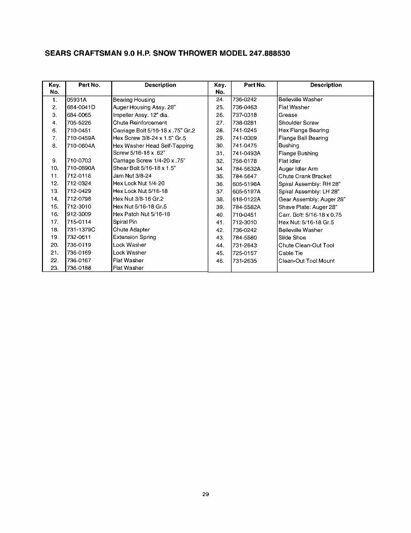
SEARS CRAFTSMAN 9.0 H.P. SNOW THROWER MODEL 247.888530
Key, Part No.No,
1. 35931A
2. 584-0041 D
3. 584-0065
4. 705-5226
6. 710-0451
7. 710-0459A
8. 710-0604A
9. 710-0703
10. 710-0890A
11. 712-0116
12. 712-0324
13. 712-0429
14. 712-O798
15. 712-3010
16. )12-3009
17. 715-0114
18. 731-1379C
19. 732-0611
20. 736-0119
21. 736-0169
22. 736-0167
23. 736-O188
Description Key, Part No.No,
Bearing Housing 24, 736-0242
Auger Housing Assy. 28" 25, 736-0463
impeller Assy, 12" dia. 26, 737-0318
Chute Reinforcement 27. 738-0281
Carriage Bolt 5/16-18 x .75" Gr,2 28. 741-0245Hex Screw 3/8-24 x 1.5" Gr.5 29. 741-0309
Hex Washer Head Self-Tapping 30, 741-0475Screw 5/16-18 x .62" 31, 741-0493A
Carriage Screw 1/4-20 x .75" 32, 756-0178
Shear Bolt 5/16-18 x 1.5' 34, 784-5632A
Jam Nut 3/8-24 35, 784-5647
Hex Lock Nut 1/4-20 36, 605-5196A
Hex Lock Nut 5/16-18 37, 605-5197A
Hex Nut 3/8-16 Gr,2 38, 618-0122A
Hex Nut 5/16-18 Gr.5 39. 784-5582A
Hex Patch Nut 5/16-18 40, 710-0451
Spiral Pin 41, 712-3010
Chute Adapter 42, 736-0242
Extension Spring 43, 784-5580
Lock Washer 44, 731-2643
Lock Washer 45, 725-0157
Flat Washer 46, 731-2635Flat Washer
Description
Betleville Washer
Flat Washer
Grease
Shoulder Screw
Hex Flange Bearing
Flange Ball Bearing
Bushing
Flange Bushing
Flat Idler
Auger Idler ArmChute Crank Bracket
Spiral Assembly: RH 28"
Spiral Assembly: LH 28"
Gear Assembly: Auger 28"
Shave Plate: Auger 28"
Cam Bolt: 5/16-18 x 0.75
Hex Nut: 5/16-18 Gr,5
Belleville Washer
Slide Shoe
Chute Clean-Out Tool
Cable Tie
Clean-Out Tool Mount
29

SEARS CRAFTSMAN 9.0 H.P. SNOW THROWER MODEL 247.888530
43
\\\\\\\\
6(23
44
27
15
Drive Clutch Cablerouted below axleand hooked here
55
58
9
\\\
NOTE: For painted parts, please refer to the list of
color codes below. Please add the applicable colorcode, wherever needed, to the part number to order a
replacement part. For instance, if a part, numbered700-xxxx, is painted polo green, the part number toorder would be 700-xxxx-0689.
Polo Green: 0689Powder Black: 0637
47
14I
32 .748
32 14J
3 /I
36
42
lO
41
11
\ 3649
7
13
43
57
,//
14
3O

SEARS CRAFTSMAN 9.0 H.P. SNOW THROWER MODEL 247.888530
Key, Part No.No,1. 618-0043
2. 618-0044
3. 618-0575
4. 656-0012A
5. 684-0014B
6. 684-0042C
7. 784-5731B
8. 684-0131A
9. 710-0599
10. 710-0809
11. 710-1652
12. 711-1267
13. 711-1268
14. 711-1364
15. 712-0711
16. 712-3017
17. 713-0233
18. 713-0374
19. 713-0413
20. 713-0472
21. 714-0507
22. 736-0142
23. 714-0474
24. 716-0102
25. 721-0263
26. 732-O2O9
27. 732-O264
28. 736-0105
29. 736-0160
Description
Degg Assembly RH
Degg Assembly LH
Shift Assembly: Steerable Drive
Friction Wheel Disc Assy,
Shift Rod Assembly
Bearing
Transmission Frame
Support Bracket Assembly
TT Screw 1/4-20 x 0.5"
TT Screw 1/4-20 x 1,25"
TT Screw 1/4-20 x .625"
Key, Part No.No.30. 736-0169
32. 736-0351
33. 736-0626
35. 737-0318
36. 738-0924
37. 741-1111
38. 741-04026
39. 741-0600
40. 741-0701
41. 746-0897
42. 746-0898B
Description
Lock Washer
Flat Washer
Flat Washer
Grease
Shoulder Screw
Hex Flange Bearing
Hex Flange Bearing
Ball Bearing
Flange Bushing
Auger Clutch CableDrive Clutch Cable
Drive Shaft
Actuator Shaft
Pin
Jam Nut 3/8-24 Gr8
Hex Nut: 3/8-16
Chain
Chain
Sprocket: 10T
SprocketCotter Pin
Flat Washer
Cotter Pin
Snap RingAdhesive: Lectite TM
Extension Spring
Extension SpringBell Washer
Flat Washer
43. 746-0956
44. 748-0190
45. 750-1161A
46. 750-1162
47. 756-0625
48. 784-559O
49. 784-5687A
50. 784-5689A
51. 784-5730A
52. 784-5740
53. 784-5732
54. 784-5733
55. 710-1233
57. 725-0157
58. 746-0950
59. 712-0703A
Steering Cable
Spacer
Support Tube: Axle
SpacerRoller Cable
Shift Bracket
Auger Clutch Cable Guide Bracket
Front Support Guide Bracket
Retaining Shaft: Actuator Drive RH
Retaining Shaft: Actuator Drive LHFrame Cover
Roller Bracket: Drive Cable
Oval C-Sunk Machine Screw
Cable Tie
Turn TriggerNut Insert
31

SEARS CRAFTSMAN 9.0 H.P. SNOW THROWER MODEL 247.888530
63
49
61
75
_6751
27
2O
4/ 67 9
19
69
81
21
62
781
28
59
68f
NOTE: For painted parts, please refer to the list of
color codes below. Please add the applicable colorcode, wherever needed, to the part number to order a
replacement part. For instance, if a part, numbered 700-xxxx, is painted polo green, the part number to orderwould be 700-xxxx-0689.
Polo Green: 0689
Powder Black: 0637
32

SEARS CRAFTSMAN 9.0 H.P. SNOW THROWER MODEL 247.888530
Key Part No.No.
1 629-0058
2 684-0008A
3 684-0053B
4 684-0066
5 684-0102
6 684-0111A
7 684-0112
8 710-0262
9 710-0442
10 710-0451
11 710-0459
12 710-0599
13 710-0896
14 710-1003
15 711-0653
16 712-0116
17 712-0415
18 712-0429
19 712-3068
20 714-0104
21 715-0138
22 720-0201A
23 720-0300
24 725-1300
25 726-0100
26 731-1300A
27 731-1313B
28 731-1317
29 731-1320
30 731-1773A
31 732-0145
32 732-0193
33 732-0705
34 732-0746
35 735-0199A
36 736-0105
37 736-0159
38 736-0506
39 736-0509
40 737-0133
Description
Harness for Headlight
Shift Arm Assembly
Lower Chute Crank Assembly
Hardware Pack*
Handle Pane{ Assembly w/Tilt
Handle Assembly Engagement LH
Handle Assembly Engagement RH
Carriage Bolt 5/16-18 x 1.50
Hex Bolt 5/16-18 x 1.5
Carriage Bolt 5/16-18 x.75
Hex Screw 3/8-24 x 1.5
TT Screw1/4-20 x 0.5"
Hex AB Tap Screw 1/4 x .62
Hex B-Tapp Screw # 10-16 x .62
Clevis Pin
Hex Ins. Lock Nut 3/8-24
Key PaN No.No.
43 746-0896
44 746-0901
45 747-0798A
46 747-0877
47 748-0362
48 748-0363
49 749-0908A
50 749-0909
51 784-5594
52 784-5604
53 784-5619A
54 784-5679
55 784-5680
56 784-5681
57 784-5682
58 712-3068
Description
Chute Deflector Control Cable
Chute Deflector Cable w/ClipShift Rod
Cam Rod
Cam Handle Lock
Pawl Handle {ock
Right HandleLeft Handle
Cable Bracket
Chute Tilt Handle
Shift Handle
Handle Support Bracket 5/8 LH
Handle Support Bracket 5/8 RH
Handle Support Bracket 3/8 LH
Handle Support Bracket 3/8 RHLock Nut 5/16-18 Thd.
Self-Threading Nut
Lock Nut 5/16-18
Lock Nut 5/16-18
Cotter Pin
Roll Pin
Chute Crank Knob
Shift Knob
Headlight
Push CapLower Chute
Cable Guide
Headlight Bezel
Upper ChuteHandle Panel
Compression Spring
Compression SpringCable Control Wire
Torsion Spring
Rubber Bumper
Bell Washer 380 x .880 x .062
Washer 5/6 I.D.
Special Washer
Special WasherGrease
59 712-3027
60 712-0287
61 736-0119
62 784-5599
63 710-04039
64 710-1880
65 736-0275
66 736-0185
67 714-0104
68 731-0851A
69 710-3015
70 711-0677
71 710-0262
72 746-0778
73 712-0121
74 705-5266
75 736-0242
76 714-0101
77 750-0785
78 747-0737
79 736-0270
80 715-0138
81 741-0475
Hex Flange Locked Nut 1/4-20 Thd.
Hex Nut 1/4-20
Lock Washer 5/16
Handle Tab
Hex Bolt 5/16-18 x 2.0"
Hex Bolt 5/16-18 x 0,75"
Flat Washer 5/16
Flat Washer 3/8 x .738 x .063"
Hairpin Clip
Chute Flange Keeper
Hex Bolt 1/4-20 x 075"
Ferrule
Carriage Bolt 5/16-18 x 150
Z Fitting
Hex Nut # 10-24
Chute Crank Reinforcement Bracket
Cupped Washer
Hairpin Clip
Spacer
Upper Chute Crank
Bell Washer
Roll Pin
Plastic Bushing
* Includes references 19 and 58 through 75
33

SEARS CRAFTSMAN 9.0 H.P. SNOW THROWER MODEL 247.888530
3\\\\
Key. Part No. DescriptionNo.
1. 712-0324 Hex Lock Nut: 1/4-20
2. 732-0705 Cable Guide
3. -- Craftsman Engine model143.039001
Key, Part NO. DescriptionNO,
1. 734-1709A- Wheel Assembly3662
2. 738-0994A Axle
3. 714-0104 Klick Pin
4. 731-04043 Spacer
\\\\,
1
34

SEARS CRAFTSMAN 9.0 H.P. SNOW THROWER
MODEL 247.888530
IMPORTANT: For a properly working machine, use Factory Approved Parts.
V-Belts are specially designed to engage and disengage safely. A substitute(non-OEM) V-Belt can be dangerous by not disengaging completely.
NOTE: For painted parts, please refer to the list of color codes below.Please add the applicable color code, wherever needed, to the part numberto order a replacement part. For instance, if a part, numbered 700-xxxx, ispainted polo green, the part number to order would be 700-xxxx-0689.
Pole Green: 0689Powder Black: 0637
1315\
\
5\\
23
21\\
21 23
\
14\\\
2
26\\
2025
\\
3 11
22
16
Key NO1.2.3.4.5.6.7.8.9.10.11,12.13.
\_19 24
Part No.
D5896A
710-0230
710-0627
710-0654A
710-0696
710-1245B
710-1652
710-3005
712-0181
731-1324
732-0710
736-0242
736-0247
DescriptionIdler Bracket
Hex Bolt 1/4-28 x 0.5" Gr.5
Hex Screw w/patch: 5/16-24 x 0.75"
Hex Washer HeadTT Sems Screw
Hex Bolt 3/8-24 x .875" Gr.8
Hex Screw w/Patch: 5/16-24 x .875"
Hex Washer Head TT
Hex Screw: 3/8-16 x 1.0"
Top Lock Jam Nut: 3/8-16
Belt Cover
Extension Spring
Bellevile Washer
Flat Washer
Key No.14.15.16.17.18.19.20.21.22.23.24.25.26.
Part No,
736-0270
736-0331
736-0505
737-0318
748-0234
748-0360
754-0346
754-0430B
756-0313
756-0569
756-0967
756-0986
756-0987
DescriptionBell Washer
Bell Washer
Flat Washer
Grease
Shoulder Spacer
Adapter PulleyV-Belt
Belt
Fiat Idler
Pulley Half
Auger Pulley
Pulley Half
Pulley Half
35

Craftsman Engine Model No. 143.039001 for CraftsmanSnow Thrower Model 247.888530
18\
87
70
305
83
119
69
30
308
"60
101
I
2526
37OH
03 323
/315
>300
282
q370C
'_" )00
36

Craftsman Engine Model No. 143.039001 for CraftsmanSnow Thrower Model 247.888530
KeyNo.
12345141515A15B161718192025262830353637384O4O414142424345474849506065697071757680818283848687899O
Par_No.
3538527652650820
309692827730699C3070065049433454299166510283466335319364606505613032235980A29826299182921629642400114001240009400104001340014278883689765103334034368963665533273A65012835262A35445A3537735319289263184530590A3537830588A2919365083365083232589611093
Key Pa_Description Qty. No. No.
Cylinder 1 92 650880Dowel Pin 2 93 650881Screw 2 100 35135Oil Drain Extension 1 101 610118Extension Cap 1 102 651024Washer 1 103 651007Governor Rod 1 110 35187Governor Yoke 1 110A 37047Screw 1 119 36448Governor Lever 1 120 36449Governor Lever Clamp 1 125 27878AScrew, Torx 1 125 27880ASpeed Control Spring 1 126 34035Oil Seal 1 127 650691Blower Housing Baffle 1 130 6021AScrew 2 130A 650727Lock Nut 1 130B 651055Crankshaft 1 135 35395Screw 1 139 33369Lock Washer 1 140 650836Lock Nut 1 149 27882Retaining Ring 1 149A 35862Piston, Pin & Ring Set (Std.) 1 150 27881Piston, Pin & Ring Set (.010" O__) 1 151 32581Piston, & Pin Ass'y.(Std.) 1 169 27896APiston, & Pin Ass'y.(.010" OS) 1 170 28423Ring Set (Std.) 1 171 28424Ring Set (.010" OS) 1 172 28425Piston Pin Retaining Ring 2 173 35350Connecting Rod Ass'y. 1 174 650128Connecting Rod Bolt 2 178 29752Valve Lifter 2 182 30088AOil Dipper 1 183 34587ACamshaft (MCR) 1 184 33263Blower Housing Extension 1Screw 1 185 33877Cylinder Cover Gasket 1 186 34667Cylinder Cover 1 186B 36652Crankshaft Bushing 1 200 34677Oil seal 1 203 31342Camshaft Seal 1 204 651029Governor Shaft 1 206 610973Washer 1 207 33878Governor Gear Asss'y. 1 209 650821Governor Spool 1 215 35440Retaining Ring 1 219 34586Screw 7 220 35438Screw 1 222 28820Flywheel Key 1 223 650378Flywheel (W/Ring Gear) 1 224 27915A
Description
Belteville Washer
Flywheel NutSolid State IgnitionSpark Plug CoverSolid State Mounting StudScrew, TorxGround WireGround WireCylinder Head GasketCylinder HeadExhaust Valve (Std.)Exhaust Valve (1/32" Os)Intake Valve(Std.)WasherScrewScrewScrewResistor Spark PlugGovernor Gear BracketScrewValve Spring CapValve Spring CapValve SpringValve Spring KeeperValve Cover Gasket
Breather BodyBreather ElementValve CoverBreather TubeScrewNut & Lock WasherScrewChoke BracketCarburetor to intake
pipe gasketIntake PipeGovernor Link
Choke SpringControl Bracket
Compression SpringTorx. ScrewTerminalThrottle LinkScrewControl KnobChoke RodChoke KnobScrewScrew, TorxIntake Pipe Gasket
Qty.
111122111111127221121122111112221
111111112111221
37 Table continued on next page

Craftsman Engine Model No. 143.039001 for CraftsmanSnow Thrower Model 247.888530Table continued from previous page
KeyNo.
260261262264A265275276277281282285287291292298300301305307308310314315322323
PartNo.
35447A65078829747B65080233272B35056315886510023301365076035985B29752309622646065066534156A3535535554354993554036205650873611111611117611118
KeyDescription Qty. No.
Blower Housing 1 325Screw 2 327Screw, Torx 2 328Screw 1 329Cylinder Head Cover 1 335Muffler 1 336
Locking Plate 1 338Screw 2 340Starter Bubble Cover 1 341Screw 1 342Starter Cup 1 343Nut & Lock Washer 4 343AFuel Line 1 350Fuel Line Clamp 4 351Screw 2 355Fuel Tank 1 364Fuel Cap 1 365Oil Fill Tube 1 370C
"O" Ring 1 370HFill Tube Clip 1 3701Dipstick 1 380Screw 1 390Alternator Coil 1 396Connector Body 1 400Terminal 1 900
9OO
Par_No.
29443353923559361097335057A65076528942341543415565056135079651060570682_32180C590574333776507673650135077358786400525907493700036450A
Description
Wire ClipStarter PlugIgnition KeyTerminalCarburetor CoverScrewScrewFuel Tank BracketFuel Tank BracketScrew
Key Switch BracketScrewPrimer BulbPrimer LineStarter HandleCarburetor Cover BracketScrewPrimer DecalChoke Decal
Warning DecalCarburetorRewind StarterElectric Starter MotorGasket Set
Replacement Engine--noneShort Block 756325C
Qty.
1121112111111111211111110
Recoil Starter
13
PartNo.590749590599A590600590679590601590678590680590412590682590750A590535
590574
Description Qty.Rewind Starter 1Spring Pin (Incl. 4) 1Washer 1Retainer 1Washer 1Brake Spring 1Starter Dog 2Dog Spring 2Pulley & Rewind Spring Ass'y 1Starter Housing Ass'y. 1Starter Rope (Length 98" x
9/64" Dia.) 1Mitten Grip Handle (Not
Included With Starter) 1
38
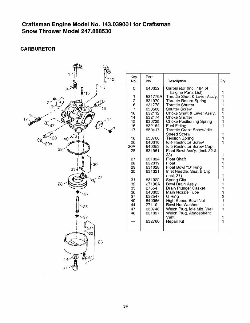
Craftsman Engine Model No. 143.039001 for CraftsmanSnow Thrower Model 247.888530
CARBURETOR
_10
I -4
IJI .-
18,.. _*" fLOf_f_ J_/.,_,_
_2o 48-.© I
_"_ 20A 29/_
3J,
28
'_',s7
I, }
40/t_
Key PutNo. No. Description Q_.
0 640052
1 631776A2 6319706 6317787 650506
10 63211214 63217415 63073516 63216417 650417
18 63076620 640016
20A 64005325 631951
27 63102428 63201929 63102830 631021
31 63102232 27136A33 2755436 64000537 63254740 64005544 2711047 63074848 631027
632760
Carburetor (Incl. 184 ofEngine Parts List)
Throttle Shaft & Lever Ass'y.Throttle Return SpringThrottle ShutterShutter ScrewChoke Shaft & Lever Ass'y.Choke ShutterChoke Positioning SpringFuel FittingThrottle Crack Screw/IdleSpeed ScrewTension SpringIdle Restrictor ScrewIdle Restrictor Screw CapFloat Bowl Ass'y. (Incl. 32 &33)Float ShaftFloatFloat Bowl "O" RingInlet Needle, Seat & Clip(Incl. 31)Spring ClipBowl Drain Ass'y.Drain Plunger GasketMain Nozzle TubeO RingHigh Speed Bowl NutBowl Nut WasherWelch Plug, Idle Mix. WeltWelch Plug, AtmosphericVentRepair Kit
111121111
111
1111
111112111
39

PorunalsodesdelafechadecompracuandoesteexpulsordenieveCraftsmanseamantenido,lubricadoypuestoapuntodeacuerdoconlasinstruccionesdeoperaciSny mantenimientoenelmanualdelproprietario,Searsreparar_,libredecostocualquierdefectodematerialodemanodeobra.
Estagarantiaseaplicapor30diassotamenteapartirdelafechadecompra,sielexpulsordenieveseusaparafinescomercialesodealquiler.
Estagarantfanocubre:Articulosdesechablesquesedesgastanduranteelusonormal,talescomozapatasdeslizantes,placaraspodaray bujias.Reparacionesnecesariasacausadeabusoonegligenciaporpartedeloperador,incluyendocigL)eSlesdobladosy lafallaenmantenerelequipodeacuerdoconlasinstruccionescontenidasenelmanualdelproprietario.
Elservici5degarantiaestadisponiblesisedevuetveelexpulsordenieveCraftsmanalcentro/departamentodeserviciodeSearsmascercanoenlosestadosunidos.
Estagarantiaseaplicasolamentemientrasesteproductoest6enusoenlosEstadosUnidos.Estagaranti_,leotorgaderechoslegalesespecificosy ustedouedetambi6ntenerotrosderechosquevariandeEstadoaEstado.
Sears,RoebuckandCo.,D817/WA,HoffmanEstates,IL60179
Especificaciones Del Producto
Caballos de Fuerza: ....................... 9
Desplazamiento ............................. 19.43 pies.cub.
Capacidad de Combustible ............ 4 cuartos
Bujfa ............................................... RJ-19LM
Motor .............................................. Modelo 143.039001
Numero De Modelo ....247:.888530 ................
Numero De Serie .............................................
Fecha De Compra ............................................
Los numeros de modelo y de serie se encuentran en elrotulo pegado al armazon del expulsor de nieve.
Usted deberia registrar el numero de serie y la fecha de
compra y guardarios en un lugar seguro para referencfafutura.
4O

ADVERTENCIA: Este simbolo indica importantes instrucciones de seguridad las cuales, si no se
respetan, podffan poner en peligro la seguridad personal y/o bienes suyos o de terceros. Lea y siga todas lasinstrucciones que aparecen en este manual antes de intentar operar esta mAquina. La falta de cumplimiento
con estas instrucciones podffa resultar en lesiones personales. Cuando vea este sfmbolo - haga caso a suadvertencia.
_1_ ADVERTENCIA: El escape del motor, algunos de sus componentes, y determinados componentes delvehfculo contienen o emiten sustancias quimicas qua de acuerdo con el Estado de California, causan cancer ydefectos de nacimiento u otros daffos reproductivos.
PEMGRO: Esta m_.quina fue construida para ser operada de acuerdo con las normas de operaci6n seguracontenidas en este manual. AI igual que con cualquier tipo de equipo eldctrico, la falta de atencidn o los errorespor parte del operador pueden resultar en lesiones graves. Esta maquina puede Ilegar a amputar manos y pies yarrejar objetos. La falta de observancia de las instrucciones de seguridad podr/a resultar en lesiones graves o lamuerte
Capacitaci6n1. Lea, comprenda, y siga todas las instrucciones que aparecen
en la m_quina yen el manual o en los manuales antes deintentar ensamblarla y operarla. Guarde este manual en unlugar segure para consultado en un futuro de manere regular ypare solicitar las piezas de repuesto.
2. Familiar[cese con todos los contreles y su operecidn. Sepacdmo detener la mAquina y desenganchar los controles.
3. Nunca permita que los niffos menores de 14 afros de edadoperen esta maquin& Los niffes de 14 afros de edad y demayor edad deben leer y comprender las instrucciones defuncionamiento y las normas de seguridad contenidas en estemanual y deben capacitarse en su uso y ser supervisados poruno de los padres.
4. Nunca permita que los adultos operen esta maquina sin lainstruccidn adecuada.
5. Los objetos arrojados pueden causer lesiones personalesgraves. Planifique un pat r6n pare arrojar nieve con el prop6sitode evitar descargar el material hacia las calles, transet]ntes,etc.
6. Mantenga a transedntes, ayudantes, mascotas y niffos por Iomenos a 75 pies de distancia de la mAquina mientres estefuncionando. Detenga la mAquina si alguien ingresa en el Area.
7. Tenga cuidado de no resbalarse ocaerse, especialmentecuando esta operando la mAquina marcha atrA.
Preparaci6n1. Inspecciene con mucho cuidado el Area donda se usar& el
equipo. Quite todes los felpudos, peri6dicos, trineos, tablas,cables y otros objetes extraffos, que podrian sat atropeUados oarrojados por 18helice / el propu[sor.
2. Siempre use anteojos de protecci6n o viseres protectoresdurante la operacion y mientres realice un ajuste o unareparecidn con el fin de proteger sus ojos.
3. No opere la mAquina sin user prendas exteriores de invierno.No use joyas, bufandas largas u otre vestimenta floja, quapodda quedar enredada en las partes m6viles. Use calzadoque contribuya al equilibrio sobre superficies resbaladizas.
4. Utilice un alargador de tres hilos con conexidn a tierra yreceptaculo pare todas las unidades con motores electricos.
5. Ajuste 18alture de 18caja del colector pare despejar superficiescon grave o g revilla.
6. Desenganche todas las palancas del embregue antes de poneren marcha el motor.
7. Nunca intente realizer ajustes mientras el motor estafuncionando, excepto cuando este especificamente indicadoen el manual de instrucciones.
8. Deje que el motor y la mAquina se ajusten ala temperatureexterior antes de comenzar a despejar la nieve.
9. Pare evitar lesiones personales o daffos materiales, tengamucho cuidado cuando manipule gasoline. La gasoline es
extremadamente inflamable y los vapores son explosivos.Pueden ocurrir lesiones personales graves cuando se derremegasoline sobre su persona o sobre su vestimenta, la cual sepuede prender fuego. Lave su piel y c&mbiese la ropeinmediatamente.
a. Utilice L_nicamente un recipiente de gasolina aprobado.b. Apague todos los cigarrillos, cigarros, pipas, y otres
fuentes de ignicidn.c. Nunca coloque combustible ala maquina en interiores.d. Nunca quite la tape de gasoline o agregue combustible
mientres el motor estA caliente o est& en marcha.e. Permita que el motor se entrie por Io menos durente
dos minutos antes de volver a abastecer concombustible.
f. Nunca coloque combustible en el tanque en exceso.Uene el tanque hasta no mAs de V2pulgada por debajodel fendo del cuello pare que haya espacio suficientepare la expansi6n del combustible.
g. Vuelva a colocar la tape de la gasoline y ajustefirmemente.
h. Si la gasolina se derrama, limpiela del motor y delequipo. Mueva la m&quina a otre Area. Espere 5minutos antes de poner en marcha el motor.
L Nunca almacene la mAquina o el recipiente decombustible en interiores cuando hay una llamaabierta, chispa o luz piloto (por ejemplo, home,calentador de agua, calentador de ambientes, secadorde rope, etc.)
j. Deje qua la unidad se enfrie pot 5 minutos antes deguardarla.
Funcionamiento1. No coloque las manes o pies cerca de las partes giretorias, en
la caja de la h_lice e del propulsor e en la canaleta dedescarga. El contacto con las partes giratorias puede amputarmanos y pies.
2. La palanca del embregue de 18helice/del propulsor es undispositivo de seguridad. Nunca deje de utilizarta, ya que de Iocont rario 18mAquina se transforma en poco segure y puedenproducirse lesiones personales.
3. La palanca del embregue de la helice/del propulsor debefuncionar fAcilmente en ambas direcciones y automaticamenteretomar ala posicidn de desenganche cuando se suelta.
4. Nunca opere 18mAquina con una canaleta de descarga que noeste en su lugar o que este dahada. Mantenga todos losdispositives de seguridad en su lugar correspondiente yenbuenas condiciones operetivas.
5. Nunca encienda un motor en interiores o en un Area sin
ventilacidn adecuada. El escape del motor contiene monoxidode carbona, un gas inodoro y mortal.
6. No haga funcionar la maquina mientras este bajo los efectosdel alcohol o drogas.
41

7. El silenciador y el motor se calientan y pueden causarquemaduras. No toque.
8. Tenga mucho cuidado cuando utilice la m&quina sobre o atraves de super[icies con grava. Mantengase ale[to paradetectar riesgos ocultos o trAnsito.
9. Tenga cuidado cuando cambie de direcci6n y cuando trabajesobre pendientes.
10. Planifique su patron para arrojar nieve para evitar descargarhacia ventanas, paredes, autom6viles, etc., de esta maneraevitando posibles daSos materiales o lesiones personalescausadas pot un rebote.
11. Nunca dirija la descarga a niSos, transeQntes y mascotas opermita que alguien se pare delante de la m&quina.
12. No sobrecargue la capacidad de la m&quina al intentar despejarla nieve a una velocidad muy r&pida.
13. Nunca opere esta m&quina sin tenet buena visibilidad o buenailuminaci6n. Siempre este seguro de mantener un buenequilibrio y que las manos est_n agarradas firmemente a lasmanijas. Camine, nunoa corra.
14. Desconecte la energfa de la h61ice o del propulsor cuandotranspo[te la m&quina o cuando no est6 en uso.
15. Nunca opere la mAquina a altas velocidades de transportesobre superficies resbaladizas. Mire hacia abajo y detr&s suyo yutilice mucho cuidado cuando de marcha atrAs.
16. Si la maquina comienza a vibrar de una manera anormal,detenga el motor, desconecte el cable de la bujfa y conectelo atierra contra el motor. Inspeccione cuidadosamente en busca dedaSos. Repare cualquier da5o antes de poner en marcha yoperar la maquina.
17. Desenganche todas las palancas de embrague y detenga elmotor antes de dejar la posici6n de funcionamiento (detr&s delas manijas). Espere hasta que la h6lice/el propulsor sedetengan pot complete antes de desobst ruir la canaleta dedescarga, haciendo todos los ajustes o inspeccionesneoesarios.
18. Nunca coloque su mano en las aberturas de descarga o delcolector. Siempre utilice la herramienta de limpiezasuministrada para desatascar la abe[tufa de descarga. Nodesatasque la canaleta de descarga mientras el motor esta enmarcha. Antes de proceder con la limpieza, apague el motor ypermanezca detr_s de las manijas hasta que todas las partesmoviles se hayan detenido por completo.
19. Utilice t]nicamente accesorias y fijaciones aprobadas pot elfabricante (por ejemplo, pesos para ruedas, cadenas deneum&ticos, cabinas, etc.)
20. Si ocurren situaciones que no estan cubie[tas por este manual,sea cuidadoso y sensato. P6ngase en contacto con el cent ro deservicio tecnico de Sears para obtener asistencia.
Mantenimiento & Almacenamiento1. Nunca toque los dispositivos de seguridad. Verifique con
regularidad si funcionan correctamente. Consulte las seccionesde mantenimiento y ajustes de este manual.
2. Antes de limpiar, reparar, O inspeccionar la mAquina,desenganche todas las palancas del embrague y detenga elmotor. Espere hasta que la h61ice / el propulsor se detengan porcompleto. Desconecte el cable de la bujfa y conectelo a tierracontra el motor para evitar que comience a funcionar de maneraimprevista.
3. Inspeccione con trecuencia los pernos y tornillos paraasegurarse de que est_n correctamente ajustados paramantener la m_quina en buenas condiciones operativas.Asimismo, inspeccione visualmente la maquina en busca deposibles dartos.
4. No cambie el ajuste del regulador del motor o aceleredemasiado el motor. El regulador controla la m_.xima velocidadoperativa segura del motor.
5. Las placas raspadoras del expulsor de nieve y zapatasdeslizantes estAn sujetas a sufrir desgaste y daSos. Para suprotecci6n personal, veritique con frecuencia todos loscomponentes y reemplace _nicamente con pa[tes gel fabricantedel equipo original (OEM). "iEI uso de partes que no cumplancon las especificaciones del equipo original puede originar unreal funcionamiento y comprometer la seguridad!"
6. Verifique los controles del embrague de manera peri6dica paracomprobar que se enganchan y desenganchan correctamente yajuste, en case de set necesario. Consulte la secci6n de ajustesen este manual de instrucciones.
7. Mantenga / reemplace las etiquetas de instrucci6n/seguridad,segL_n sea necesario.
8. Cumpla con las [eyes y regulaciones de eliminaci6n adecuadaspara gas, aceite, etc., para proteger el medio ambiente.
9. Antes de almacenar la mAquina, haga funcionar la m_quinadurante unos pocos minutos para sacar toda la nieve que hayaquedade en la maquina y evitar asi que la helice / el propulsorse congelen.
10. Nunca almacene la maquina o el recipiente de combustible eninteriores donde haya una llama abierta, chispas, o [uz pilotocomo las que se encuentran en calentadores de agua, hornos,secador de ropa, etc.
11. Siempre consulte el manual de instrucciones para leer lasinstrucciones correctas sobre almacenamiento de la m&quinatuera de temporada.
Su responsabilidadLimite el uso de esta m_quina el_ctrica a personas quelean, comprendan y sigan las advertencias e instrucciones
contenidas en este manual y que aparecen en la m_quina.Las etiquetas de seguridad se muestran a continuaci6n
para su referencia.
t.KE_ tLW_,YFH_81__OTAI[_ I_ELL[_AtlOAUGER.C8HT_TWITHIMP£LLERQ_A_J_R_ _P_T/tI_ HAII_ .l_riFEEr_
A_D 8E_AIHBEHINDHAH_LE8L_rnLALLM_VIN_ PANTSHAYEST_PPEPB_OREUNCLOGGINGDRSERIIICI_ M,_CHINE.
42

Desplieguelaferreteriadeacuerdoconlailustraci6nparafinesdeidentificaci6n.Laspiezasest_nilustradasalamitaddesutamaSoaproximadamente.Losnt3merosdepiezasemuestranentrepar_ntesis.(Elcenjuntodeferreteriapuedecentenerarticulosadicionalesquenoseusanensuunidad.)
C
A
Perno hexagonal(2)
_ -.,,
Arandela de segurJdad (4)
,©m
__ 5/16-18 x 1.75
Perno hexagonal (2)
_._ 3/16-18 x .75
Ateta delmango (2)
,/
B
D
Broche decabello (1)
_/_oche de cabello (2)
i
Casquillo
Arandela plana (2) (_ (1)
Piezas de Repuesto
i
"_ Pemo deI
corte (2)
Arandela de /_
seguridad (2)
E Perno._hexagona._ (6) /,_\ rT_o¢Srd_l_) [_
Ret_n del reborde de la canaleta (3) _1
F
G t0 IlllllllI_IllllllllllllllllllllllIOII
TomilloPhillips(2) _I
_i_toi,l_)de /_ _ _ _
Arnarre del cable (2)
43

Panelde Mango,Mangos
Parte
derecha _.
Partedelantera
Parteposterior
Parteizquierda
\Manivela dela canaleta
Vara decambios
Conjunto de
ferreteria
Figura 1
IMPORTANTE: Esta unidad ha sido despachada con aceite
del motor paro sin gasolina en el motor. Despu6s delensamblado, yea la secci6n de OPERACION de este
manual para selecci6n y Ilenado de combustible.
Extraccion De La Unidad De La CajaCotte las esquinas de la caja.Extraiga todas las inserciones de empaque..Ruede el expulsor de nieve fuera de la caja.Antes de descattar la caja, asegt3rese que se hayanextraido todas las pattes y la Iiteratura.
Piezas SueltasSu expulsor de nieve ha sido completamente ensambladode f&brica, excepto el mango y el panel del mango, elconjunto de la canaleta de descarga, el conjunto de lamanivela de la canaleta y la vara de cambios. Esas pattes sedespachan sueltas en la caja. (Vea la Figura 1)
a. Conjunto del mango y panel del mangob. Canaletac. Conjunto de la manivela de la canaletad. Varadecambiose. Conjunto deferreter_af. Conjunto deferreteriadeferreteria
Herramientas Requeridas1. Llaves de 1/2", 7/16", 3/8" o un juego de Ilaves
ajustables
2. Un juego de destornilladores de cabezal phillips3. Embudo
Antes del ensambladoAntes de ensamblar el expulsor de nieve ase_ldreseque el cable de la bujfa est_ desconectado y al6jese dela bujfa.
NOTA: Para determinar los lados derecho e izquierdo
de su expulsor de nieve, p_rese detr_s de la unidad
con el motor en la posici6n mas alejada de usted. Vea
el recuadro de la Figura 1.
Fijacion Del Conjunto Del MangoExtienda los cables de control y coloque el con junto delmango y panel del mango sobre el piso. Vea la Figura 2.Coloque los dos extremos de los mangos sobre elbastidor del expulsor de nieve como Io indican lasflechas de la Figura 2. Para su comodidad, puedecolocar la canaleta de descarga en la abertura de lacanaleta. Alinee los dos orificios inferiores en cadamango con los orificios correspondientes en el bastidordel expulsor de nieve.
44

Canaleta de
Alinee orificios aquf
arandela de seguridad del mismo grupo en el conjunto deferreterfa No apriete en este momento.Acople el mango izquierdo de la misma manera. Noapriete en este momento.
Fijacion De La CanaletaColoque el conjunto de la canaleta sobre la abedura dela canaleta, con la abettura en el conjunto de la canaletaenfrentando la parte delantera de la unidad.
NOTA: Aseg#rese que los cables de la canaleta est#nrectos mientras ensambla la canaleta.
Coloque la guarda de la brida de la canaleta (lado pianohacia abajo) debajo del reborde del conjunto de lacanaleta segQn se muestra en la Figura 4. UstedencontrarA las guardas de la brida de la canaleta en elGrupo E del conjunto de la ferreterfa.lnserte el perno hexagonal de 1/4-20 del grupo E delconjunto de ferreteria (en la pAgina 6) a trav6s de laguarda de la brida de la canaleta y del conjunto de lacanaleta segQn se muestra en la Figura 4. No ajuste eneste momento. Gire la canaleta para instalar todas lasguardas de la brida.
Figura 2
Asegure el orificio inferior en el mango al bastidor delexpulsor de nieve utilizando pemos hexagonales 5/16x.75" y la arandela de seguridad del conjunto deferreteria (grupo A en la pAgina 5). No apriete en estemomento. Vea Figura 3.
Acople la aletadel mango
aqui
Aco_le la arandelade seguridad y el pemo
hexagonal aqui
NOTA:La rueda derecha y lacubierta del propulsor se han quitadodel dibujo aqui para poder ver con m_s claridad.
Figura 3
Coloque una aleta del mango, incluida en el conjunto deferreterfa (grupo A en la pAgina 5), sobre el orificiosuperior en el mango de manera que el oontorno de laaleta del mango coincida con la del mango. Vea Figura 3.Asegure la aleta del mango al expulsor de nieveutilizando un perno hexagonal (5/16 x 2.0 de largo) y la
\ la canaleta\
Figura 4
Despu6s de ensamblar todas las tres guardas de la bridade la canaleta, ajt3stelas y afloje 1/4 de vuelta parapermitir un movimiento mAs fAcil de la canaleta. Use dos(2) Ilaves de 7/16".
Fijacion De La Manivela De LaCanaleta
Usted puede tener que aflojar los pernos del carro y lascontratuercas hexagonales que aseguran el sopoiteinferior de la manija de la canaleta a la prolongaci6n dellado izquierdo del conjunto de la canaleta. Vea la Figura5.
/
inferior de la canaleta Perno del carro
Figura 5
45

Coloqueunaarandelaplanade3/8deDI(delgrupoFdelconjuntodeferreteria)enelextremodelamanijadelacanaleta,acontinuaciSninsetteelextremodelamanijaenelorificiodelcasquillopl_sticoenelsopor_edelamanijadelacanaleta.VealaFigura6.Coloquelaotraarandelaplanade3/8deDI(delmismogrupodeferreteria)alextremodelamanijadelacanaletae inserteelbrochedelcabellodentrodelorificioalextremodelamanijadelacanaleta.VealaFigura6.Ajusteelsopor_edelacanaletademaneraquelaespiralenlamanijadelacanaletaseenganchecompletamenteconlosdientesdelconjuntodelacanaleta.Ajustebienlastuercasenelsoporteinferiordelamanijadelacanaleta.
UsandounaIlave,ajusteelpernohexagonalylatuercahexagonalenelsoportesuperiordelamaniveladelacanaleta.Usandolamaniveladelacanaleta,girecompletamenteesta01tima, para asegurar que se mueve libremente.Deslice los cables que se extienden desde el panel delmango a la canaleta dentro de la gufa de cable ubicadaal tope del motor. Vea la Figura 8.Asegure toda la ferreteria suelta en el con junto el mangoy panel del mango ahora.
Cable Guia deCable
Pasador
/Arandela plana
Casquillo pl_stico
Manija dela canaleta
Arandela plana
Figura 6
Deslice la manija superior de la canaleta dentro de lamanija inferior de la canaleta seg0n se muestra en laFigura 7. Alinee los orificios en las dos partes de lamanija de la canaleta, y asegure con el broche delcabello del grupo F del con junto de la ferreteria.Gire completamente la canaleta, usando la manija de lacanaleta, para asegurarse que se mueve libremente.Usando una Ilave inglesa ajuste el perno hexagonal y latuerca hexagonal en el soporte de la manija superior dela canaleta.
Cable de
la canaleta'\\\
Q Manijasuperior
de laI canamta
Soporte de laManija dela Canaleta
Manija inferiorde la canaleta
Figura 7
Figura 8
Fijacion De Los Cables Del EmbragueLos cables de control del embrague est_n fijados a la
limpiadora de nieve. Si los cables est_n fijados al tope delmotor con amarras de cable, corte las amarras ahora. Los
extremos en Z de los cables del embrague estfinenganchados dentro de las empufiaduras de cada manija.
Aseg0rese que haya una contratuerca enroscada todahasta la porciSn enroscada del adaptador en Z; seproveen extras en el conjunto de ferreteria. Vea laFigura 9. Coloque la manija del embrague en la posici6nelevada (up).
,_ _F AdagtadorMango del _= en Zembrague -_-_Contra-\ _tuerca de
_ / _ seguridad
Figura 9
Gire hacia arriba la espiral sin fin izquierdaasegurAndose que el cable est_ encaminadocorrectamente en las guias del rodillo del cable ubicadosen la parte posterior inferior de la unidad.Sujete el extremo del cable en el tambor de manera queel casquillo gire libremente sin torcer el cable. Enrosqueel casquillo en el adaptador en Z. Para aliviar la tensi6nusted puede tenet que tirar ligeramente del cable.Mantenga girando el casquillo sin torcerel cable.Usted alcanzarA un ajuste correcto cuando haya unexceso minimo en el cable pero no est_ ajustado. Sujetelas _reas planas del casquillo con pinzas y ajuste lacontratueroa oontra el casquillo.
46

PRECAUCION: Los cables se aflojar_n si usted no ajusta lacontratuerca.
ADVERTENCIA: NO debe haber tensi6n en
ninguno de los cables del embrague con elpropulsor o la empufiadura del embrague de la
espiral sin fin en la posici6n desengan-chada(up). Esos embragues sen una caracterfstica de
seguridad. No cancele su funci6n permitiendoque exista tensi6n en cualquiera de los cables
con los embragues desenganchados.
Fijacion De La Vara De CambiosColoque la palanca de cambios en la posici6n de sexta(6) velocidad.Coloque el extremo doblado de la vara de cambio dentrodel orificio en el conjunto del brazo de cambios. Vea laFigura 10. Asegure con la arandela plana de 5/16 y elbroche de cabello del con junto de ferreterfa (grupo C).Comience a enroscar el casquillo (incluido en el mismogrupo en el conjunto de ferreteria) dentro del otroextremo de la vara de cambios. Tiene que alinearse conel orificio superior en la palanca de cambios (debajo delpanel del mange). Mientras alinea el casquillo, empujehacia abajo la vara de cambios y el conjunto del brazo decambios tanto como pueda.
Control dela h61ice
Embrague del Palanca _ontrolpropulsor de cambios _ de lade _/rtdistancia detracci6n la canaleta
del cabello
unto delbrazo de cambios
Brochedel cabello
- Vara decambios
\
Arandela plana
Figura 10
Una vez que el casquillo se deslice dentro del orificio,girelo en sentido contrario alas agujas del reloj unavuelta completa e inserte en el orificio en la palanca decambios.
NOTA: Puede ser necesario mover la palanca decambios fuera de la posiciSn de sexta velocidad ymoverla hacia la posiciSn de quinta velocidad hastaque el casquillo se deslice dentro del orificio sin fuerza.
Asegure el casquillo a la palanca de cambios con otraarandela plana de 5/16 y broche del cabello del grupo Cdel conjunto de ferreteria. Vea la Figura 10.Antes de operar el expulsor de nieve, asegL_rese deinspeccionar el ajuste correcto de la vara de cambiossegL_nlas instrucciones de la secci6n de Ajustes.
Fijacion De Los Gatillos De GiroAlimente el cable del gatillo a traves del lado exterior dela ranura en el panel del mango. No alimente el cable atraves del mismo lado de la ranura que adaptador en Z.
Conjunto del
tAadma_t°ad°r_ ,_ _/_li I01
Cable \ _-_( l,/_/-_-j g_atillo
:&_.zeFo-,eoo"/_ Ran_ra'a'a'a'a'a'a'a'a'_r:_
Figura 11
NOTA: Usted no puede tirar del cable fuera delarmaz6n del mismo, cuando el cable estecorrectamente instalado.
Asegt3rese que el cable del gatillo de la mano derechaest_ encaminado al frente del cable propulsor detracci6n.Coloque el adaptador del tambor del cable dentro delorificio del gatillo. Usted puede encontrar los gatillos y laferreteria relacionada en el grupo G del conjunto deferreteria. Tire del cable y girelo alrededor del fondo delgatillo, con el cable interior en la ranura, hasta que elextremo del cable pueda ser empujado dentro delarmaz6n del gatillo y calzado firme. Vea la Figura 12.Ponga el disparador derecho de la vuelta en la posici6npor debajo de la manija derecha, lnserte el tornillo, delgrupo G del paquete del hardware, en el agujero en lamanija y la tuerca de la aut6gena moldeadas en laasamblea del disparador de la vuelta. Vea la Figura 12.Apriete el tornillo con un destornillador de Philips. Repitaen el lade izquierdo.
e con el tomilloGatillo de giro
triggerTriggercable del gatillo
Figura 12
Asegure el cable del gatillo de giro a la derecha al mangoderecho inferior, usando el amarre de cable provisto enel conjunto de ferreteria. Vea la Figura 13.
Amarre del cabl_
Cable del gatillo
Figura 13
47

Asegure el cable del gatillo de giro izquierdo de la mismamanera. CorSelos extremes excesivos de cada amarrede cable.
NOTA: El amarre del cable del lado derecho debeusarse para evitar el contacto con el brazo m6vil decambios de la transmisiSn.
Cableado de la LdmparaEnvuelva el cable de la I_mpara hacia abajo del mangoderecho. Enchufe el cable dentro del cable guia delalternador debajo del tanque de combustible. Vea laFigura 14.
Cable del alternador
Cable de lal_mpara
Alternador
Nota: las ruedas han sido omitidasdel dibujo por razones de claridad
Figura 14
IMPORTAWrE: Ensamble su expulsor de nieve, acontinuaciSn inspeccione los ajustes segt3n las instruccionesy efectt3e los ajustes finales necesarios antes de operar launidad. El no seguir las instrucciones puede causar averias alexpulsor de nieve.
Herramienta de limpieza de lacanaleta
Esta herramienta es sujetada con un amarre del cable ala parte posterior de la caja de la h_lice para fines detransporte. Corte el amarre del cable y extraiga laherramienta antes de operar el expulsor de nieve.
Ajustes Finales
Control Deh_lice
Control de la H_licePara inspeccionar el ajuste del control de la helice,empuje hacia adelante sobre la empufiadura izquierdadel embrague hasta que est_ comprimido elamortiguador de goma. Debe haber exceso en el cabledel embrague. Vea la Figura 15.Suelte la empufiadura del embrague. El cable debe estarrecto. Asegt3rese de poder bajar completamente elmango de control de la helice contra el mango izquierdo.Si es necesario ajustar, afloje la tuerca de seguridadhexagonal y enrosque el cable hacia adentro (paramenos exceso) o hacia afuera (para m_s exceso).Vuelva a inspeccionar el ajuste. Ajuste la tuerca deseguridad contra el cable cuando se alcanza el ajustecorrecto.
Control del Propulsor de TraccibnPara inspeccionar el ajuste del control del propulsor detracciSn y de la palanca de cambios, mueva la palancade cambios todo el recorrido hasta la sexta (6) posiciSn.Con el control del propulsor de tracciSn desenganchado,mueva los gatillos hacia arriba hasta el mango y acontinuaciSn empuje el expulsor de nieve hacia adelantepara verificar que giren las wheel.Suelte el control del propulsor de tracciSn y tirenuevamente del arrancador. La unidad no debemoverse.Antes de proceder con el ajuste, inspeccione paraasegurarse que la bujia esta desconectada.Si el control del propulsor de tracciSn requiere ajustes,afloje la tuerca de seguridad en el cable del propulsor detracciSn y enrosque el cable una vuelta. Vuelva ainspeccionar el ajuste y repita segL_nsea necesario.
Ajuste de la Zapata DeslizantePuede cambiarse el espacio entre la plata raspadora y el
suelo ajustando la zapata deslizante.Retorne la palanca de transferencia de peso (mostradaen la Figura 16) a su posiciSn normal antes de ajustar laszapatas deslizantes.Para una eliminaciSn estrecha de nieve, ajuste laszapatas deslizantes tan altas como sea posible paraminimizar la separaciSn entre la placa raspadora y elsuelo.Para eliminar la nieve de terrenos irregulares tales comepedregullo, ajuste las zapatas deslizantes hacia abajopara crear suficiente espacio entre el berde inferior de laplaca raspadora y el suele.Ajuste las zapatas deslizantes aflojando las cuatrotueroas hexagenales y los pernos del carro y moviendolas zapatas deslizantes a la posici6n deseada.Asegurese que toda la superficie inferior de la zapatadeslizante est6 apoyada sebre el suelo para evitar undesgaste irregular de las zapatas deslizantes. Vea laFigura 16.Vuelva a ajustar seguramente las tuercas y los pernos.
Extrernoen Z J
Contratuerca F
Cable Decontrol de h_lice
Figura 15
Zapata desliz_nte _
Pernos del la carro
Figura 16
48

Conociendo a su expulsor de nieve
Por favor lea este manual del usuario y las etiquetas de seguridad anexadas a la unidad antes de operar suexpulsor de nieve. Compare la ilustraci6n que figura mas abajo con su equipo para conocer la ubicaci6n ycaracterfsticas de los diversos controles del mismo. Guarde este manual para referencia futura.
Control del propulsorde traccion Palanca de
cambios Control de distancia de la canaleta
Control de la h_lice
Lampara_Cana|eta de Manivela de la canaleta
descarg_ Tanque de\ gasolina
Herramienta\ Tapa de combustible \de limpieza \de la canalet Tap6n de lenado de aciete_ \\\
\ \ \\ \ \
\\ Bujia \ \\\ Manivela de giro\ a la derecha
H_liceZapata deslizante
Silenciador _
Arrancadorel_ctrico
CebadorLlave de encendido
Arrancador de retroceso
Figura 17
Conozca Su Expulsor De Nieve
Propulsor De Traccion/Seguro Del EmbragueDe La Espiral Sin FinEl embrague del propulsor de tracci6n est_ ubicado en elmango derecho. Accione el embrague del propulsor detracci6n para enganchar la rueda motdz. Suelte para parar.Esta misma palanca tambien fija el embrague de la espiralsin fin de manera que se puede girar la manijade la canaleta sin interrumpir el proceso de limpieza denieve. Si se engancha el embrague del propulsor de laespiral sin fin con el embrague del propulsor de traccci6nenganchado, el operador puede soltar el embrague delpropulsor de la espiral sin fin (en el mango izquierdo)ylas espirales sin fin permanecerAn enganchadas. Suelte elembrague del propulsor de tracci6n para detener lasespirales sin fin y la rueda motriz (debe soltarse tambien elembrague del propulsor de la espiral sin fin).
Control De La Helice
El embrague del propulsor de la espiralsin fin est_ ubicado en el mangoizquierdo. Apriete la empu£_adura delembrague para enganchar las espiralessin fin. Suelte para detener la acci6n delimpieza de nieve. (Debe soltarsetambien el embrague del propulsor detracci6n).
Palanca Del Gatillo
Los gatillos para giro izquierdo y dereeho est_n ubicados dellado inferior de los mangos y se usan para ayudar a manejarsu limpiadora de nieve. Accione el gatillo de giro dereehocuando gire a la derecha y el gatillo izquierdo cuando gire ala izquierda.
Control Del AceleradorElcontroldel acelerador est_ubicadoan el motor.Regulalavelocidad del motor. AI soplar la nieve, siempre hagafuncionar el motor con el acelerador en la posici6n r_pida.
CUMPLE CON LOS REQUERIMIENTOS DE SEGURIDAD ANSI B71.3Los expulsores de nieve Sears conforman con las normas de seguridad del American National Standards Institute
(ANSI).
49

Interruptor De Encendido De SeguridadEl interrupter de la Ilave de encendido debe insertarsecompletamente en el interrupter antes que arranque la
unidad. No intente girar la Ilave.
Valvula De Corte De Combustible
La v_lvula de corte de combustible, ubicada debajo deltanque de combustible controla el fluje de combustible deltanque. Asegt3rese que no est_ en la posici6n "off" antes dearrancar el motor.
Manivela De La CanaletaLa manivela de la canaleta est'. ubicada
del lade izquierdo de la limpiadora denieve.
Para cambiar la direcci6n en la cual selimpia la nieve, gire la manija de lacanaleta come sigue:
Gire la manija en el sentide de las
agujas del reloj para descargar a la izquierda.Gire en sentido centrarie alas agujas del reloj para
descargar a la derecha.
Palanca De CambiosLa palanca de cambios est_ ubicada en el
centre del panel del mango. La palancade oambios puede moverse a una deecho posiciones. Use la palanca decambios para determinar la velocidadsebre el suelo.Avance--una de seis velocidades. La
posici6n nL_mero uno (1) es la m_s lenta.La posici6n ntTmero seis (6) esla m_s r_pida.Retreceso--dos velocidades de
retroceso (R). La "R" m_s cercana al
operador (tede hacia atr_s) es la m_sveloz de las dos.
CLOCKWISE TO
DISCHARGE LEFT
COUNTER CLOCKWISETO DISCHARGE RIGHT
5--
4--
3--
2--
1--
Control De Inclinacion De La
Canaleta
La distancia a la que se despide la nievepuedeajustarse ajustande el _ngule delcenjuntode la canaleta.Muevael controlde inclinaci6n hacia adelante paradisminuir la distancia, hacia atr_s paraaumentarla.
RI--
R2=
Herramienta De Limpieza De CanaletaLa herramienta de limpieza de canaleta est_ disefiadapara despejar una canaleta de descarga obturada. Vea la
p#,gina 53 para instrucciones sobre c6mo utilizadacorrectamente.
ADVERTENCIA: Nunca utilice su mane para
limpiar una canaleta de descarga obturada. Apagueel motor y permanezca detrAs de las manijas hasta
que todas las pattes m6viles se hayan detenideantes de preceder a desatascar.
Controles De Direccibn De
RuedaLos controles de direcci6n de ruedaizquierda y derecha est_n ubicados enla parte inferior de los mangos.
Apriete el control derecho para girar hacia la derecha;apriete el control izquierdo para girar hacia la izquierda.
NOTA: Haga funcionar el expulsor de nieve en areasabiertas hasta que est# familiarizado con estoscontroles.
Zapata deslizante
La posici6n de la zapata deslizante est_ determinada per
la condici6n del terreno del que se debe sacar la nieve.Cuanto m&s alto sea el nivel de la nieve, m_s baja debe
estar la zapata deslizante. Ajuste segQn sea necesario.
Detencion Del Expulsor De NievePara detener la expulsi6n de nieve, desenganche lapalanca del prepulsor de la helice.Para apagar el motor, empuje la palanca de control delacelerader a OFF y extraiga la Ilave de encendido. Nogire la Ilave.
Antes de poner en marcha el motor
Llene Con Gasolina
ADVERTENCIA: La gasolina es
inflamable; tenga mucho cuidado cuando la
manipule o la almacene.
No coloque combustible en el tanque mientras
el expulsor de nieve est_ funcionando, cuandoest_ caliente o cuando est_ un area cerrada.
Mantenga su expulsor de nieve a distancia deuna llama abierta o de una chispa el_ctrica y no
fume mientras est_ Ilenando el tanque concombustible.
Nunca Ilene el tanque de combustiblecompletamente. Uene el tanque a 1/4"-1/2" de
distancia de la parte superior para que hayaespacio suficiente para la expansi6n delcombustible.
Siempre Ilene el tanque de combustible en
exteriores y utilice un embudo o pico para evitarderrames.
Asegt3rese de limpiar el combustiblederramado antes de encender el motor.
Almacene la gasolina en un recipiente limpio, aprobado ymantenga la tapa en su lugar en el recipiente.Asegt3rese de que el recipiente del cual vierte la gasolinaeste limpio, libre de 6xide y de otras partfculas extrafias.Se provee una tapa de plAstico dentro de la abertura deIlenado de combustible en el tanque de combustible.Saque y deseche esta tapa antes de Ilenar el tanque.Utilice la otra tapa del tanque de gaselina para cerrarluege del Ilenado.
50

Lleneeltanquedecombustiblecongasolinalimpia,sinnueva,paraautom6vilsinplome.AIfinalizareltrabajo,vacfeeltanquedecombustiblesielexpalserdenievenovaasetusadedurante30dfasemAs.VeainstruccionesdealmacenamientoenlapAgina25deestemanual.
PRECAUCl6N: La experiencia indica que loscombustibles con mezcla de alcohol (llamadosgasohol) o los que utilizan etanol o metanol puedenatraer la humedad que resulta en la separaci6n yformaci6n de _.cidos durante el almacenamiento. Elgas acido puede daSar el sistema de combustiblede un motor durante et almacenamiento. Paraevitar problemas del motor, et sistema decombustible debe vaciarse antes de almacenar por30 dfas o mas. Drene el tanque de gasolina, pongaen marcha et motor y dejeto andar hasta que laslfneas de combustible y el carburador esten vacfos.Utilice combustible nuevo la pr6xima temporada.Vea instrucciones de almacenamiento paraobtener informaci6n adicionaL Nunca utiliceproductos de limpieza del motor o del carburadoren et tanque de combustible o puede resultar endaSos permanentes.
Llenado De AceiteEl motor fue enviado con aceite en el motor. Controle el
nivel de aceite antes de cada operaci6n y asegt3rese de
que haya aceite suficiente en el motor. Vea lasinstrucciones en la p_gina 18 para el procedimientocorrecto.
Para Poner En Marcha El Motor
Arrancador Eldctrico
_, ADVERTENCIA: El arrancador el_ctricoest_ equipado con un cordSn de potencia de
tres conductores y un enchufe y est_ diseRadopara operar con una corriente casera de 120voltios de CA. Debe conectarse
apropiadamente a tierra en todo momento para
evitar la posibilidad de un choque el_ctrico quepuede ser daSino para el operador.Observecuidadosamente todas las instrucciones.
Determine que el cableado de su casa es unsistema conectado a tierra de tres conductores.
Si no est_ seguro pregunte a un electricistalicenciado. No use este arrancador el_ctrico
bajo ninguna condici6n si el sistema decableado de su casa no es un sistema de tres
conductores conectado a tierra. Si el sistemade cableado el_ctrico de su casa est_
conectado a tierra pero no est& disponible un
recept_culo de tres orificios en el punto dondese usar_ normalmente el arrancador, debe
instalarse uno por un electricista licenciado.
AI conectar el cordSn de potencia, conecte siempreprimero el cerd6n al arrancader del motor, a centinuaci6nenchufe el otro extreme a un recept_culo de tres orificiosconectado a tierra.
AI desconectar el cordsn de potencia, desenchufesiempre primere el extremo del recept_culo de tresorificies cenectado a tierra.
Arranque Del Motor
(Vea la Figura 18.)
ADVERTENCIA: Apague el motorinmediatamente si la unidad muestra se_ales
de movimiento (rueda motriz o espirales sin fin)con las empuRaduras del embrague
desenganchadas. Reajuste segt3n lasinstrucciones en la secci6n de "Ajuste final" de
las instrucciones de Preparaci6n.
Fije el cable de la bujfa a la bujfa. AsegL_rese que el buclede metal al extremo del cable de la bujfa (dentre de labota) est_ bien fijo a la punta de metal de la bujfa.Asegt3rese que la v_lvula de corte de combustible esteen la posici6n abier_a (vertical).Asegt3rese que las palancas del embrague del propulserest_n en la posici6n desenganchada (suelta).Mueva el control del acelerador a la posici6n FAST(RAPIDA).lnserte la Ilave de encendido en la ranura. AsegtTreseque calce en su lugar. No gire la Ilave.
Fije el cablede la bujia
Presioneel bot6n
lnserte-_la Ilave
el c .J_Conecte al
cord6nelectrico
Gire elregulador
\Tire del mango
Figura 18
En el caso de arranque el_ctrico solamente siga los trespr6ximos pasos.
Gire la perilla del regulador a la posici6n OFF.Oprima el bot6n del cebador mientras cubre el orificio deventilaci6n. Saque el dedo del cebador entre cebados. Nocebe para arrancar un motor caliente.Si la temperatura es mayor de 15 grados Fcebe dos o tresveces y cuatro veces si es menor de 15 grados F.Conecte el cord6n de potencia a la caja del interrupter enel motor. Enchufe el otro extremodel cord6n de potencia a un recept&culo de tres orificios,conectado a tierra, de 120 voltios de CA.Optima el bot6n del arrancador para intentar arrancar elmotor. Cuando el motor arranque,suelte el bot6n del arrancador y mueva el reguladorlentamente a FULL (PLENO), y a continuaci6ngradualmente a la posici6n OFF. Si el motor vacila,
51

muevaelreguladorinmediatamentealaposiciSnFULLyacontinuaciSnmuevagradualmentealaposiciSnOFF.
Paraelarranque de tettoceao solamente siga los tresprSxirnos pasos:
Gire la perilla del regulador a la posiciSn FULL. Coloqueel regulador en la posiciSn OFF en lugar de la posiciSnFULL, si el motor todavfa est_ caliente.Optima el botSn del cebador dos o tres veces. Optima elbotSn del cebador una vez solamente, si el motor estAcaliente.Sujete el mango del arrancador y tire lentamente de lasoga hasta que comience a ejercer m_s resistencia.Permita que la soga se enrolle lentamente. TirerApidamente del mango del arrancador. No permita queel mango retroceda bruscamente. Permita que se enrollelentamente mientras sujeta firmemente el mango delarrancador. Repita hasta que el motor arranque. Amedida que el motor se calienta y comienza a funcionarsuavemente, gire lentamente la perilla del regulador a laposiciSn OFF. Si el motor vacila, regrese a regulador enFULL y a continuaciSn mueva lentamente a la posiciSnOFF.
Como Apagar El MotorHaga funcionar el motor por unos pocos minutos antesde apagar para ayudar a secar la humedad del motor.Proceda como sigue para avitar una posiblacongelaci6n del arrancador.Arrancador eldctrico: Conecte el cord6n de potencia ala caja del interruptor del motor, a continuaci6n a unrecept_culo de 120 voltios de CA. Con el motorfuncionando, oprima el botSn del arrancador y gire elarrancador pot varios segundos. El sonido raro emitido algirar el arrancador no daSar_ el motor o el arrancador.Desconecte primero el cordSn de potencia delrecept_culo y a continuaciSn de la caja del interruptor.Arrancador a retroceso: Con el motor funcionando,tire de la soga del arrancador con una pasada r_pida ycontinua con todo el brazo, tres o cuatro veces. El tirar dela soga del arrancador producir_ un sonido intenso degolpeteo, que no es daSino para el motor o el arrancador.Para apagar el motor, empuje todo hacia abajola palanca del acelerador o saque la Ilave de encendido.No gire la Ilave. Desconecte el cablede la bujia de la misma para evitar un arranqueaccidental mientras el equipo est_ desatendido.
NOTA: No pierda la Ilave de encendido. Mantengala enun lugar seguro. El motor no arrancara sin la Ilave deencendido.
Limpie toda la nieve y humedad de la cubierta delcarburador en el _rea de las palancas de control.Tambien, avance y retroceda varias veces las palancasde control. Deje la palanca de control del acelerador en laposici6n STOP u OFF. Deje el control del regulador en laposici6n FULL.
Enganche De La PropulsionCon el motor funcionando cerca de la velocidad m_xima,mueva la palanca de cambios a una de las posiciones deforward (avance) o alas dos de reverse (retroceso).Seleccione una velocidad apropiada para lascondiciones de nieve existentes. Use las velocidadesm&s lentas hasta que est_ familiarizado con la operaci6nde la limpiadora de nieve.Optima la empuSadura del embrague de la espiral sin finizquierda contra el mango, para engancharla.Mientras la empuSadura del embrague de la espiral sinfin est_ enganchada, optima la empuSadura delembrague del propulsor derecho.Suelte la empuf_adura del embrague de la espiral sinfin izquierda, solamente. El mecanismo de interbloqueodebe mantener el embrague izquierdo enganchadohasta que se suelte el embrague derecho.
NOTA: NUNCA mueva la palanca de cambios sinsoltar primero el embrague del propulsor.
Manejo De La Limpiadora De NieveLas palancas de los gatillos est_n ubicadas en laparte inferior de los mangos y se usan para manejarsu limpiadora de nieve.
NOTA: El embrague del propulsor debe estarenganchado al usar los gatillos para manejar lalimpiadora de nieve.
Para girar a la derecha, optima la palanca del gatilloderecho y gufa la limpiadora de nievehacia la derecha.Para girar a la izquierda, oprima la palanca del gatilloizquierdo y gufe la limpiadora de nieve hacia la izquierda.Optima ambos gatillos para transporlar la unidad cuandoel motor no est_ funcionando.
NOTA: Esos controles deben usarae mientras operasu limpiadora de nieve en areas abiertas, hastafamiliarizarse con su operaci6n.
Instrucciones Abreviadas de Arranque
Expulsorde Cable Palancas Controldel Llavede Regulador Cord6nde Cebador Arrancador DespuesdeNieve dela propulsoras acelerador encendidc )otencia arrancar
bujfa
Arrancador Conecte Suelte Muevaa Presione Muevaa Conectea -- Presioneel 1. Suelteelbot6nEl_ctrico FAST )ara FULL la fuente bot6n 2. Mueva el
calzar Cebado regulador a Off3. Desconecte elcord6n
Arrancador Conecte Suelte Muevaa Presione Muevaa -- Cebe Tiredel 1. Suelte el mangode FAST )ara FULL mango 2. Mueva elRetroceso calzar regulador a Off
52

Enganche De Las Espirales Sin FinOptima la empu_adura del embrague de la espiral sin fincontra el mango izquierdo, para enganchar las espiralessin fin y comenzar la acci6n de despedir la nieve. Sueltepara detener las espirales sin fin (debe soltarse tambi6nla empuSadura del embrague del propulsor de tracci6n).Puede fijarse tambi_n el embrague del propulsor de laespiral sin fin de manera que usted pueda girar la manijade la canaleta sin interrumpir el proceso de despedirnieve. Refierase a "Propulsi6n de Tracci6n/Fijaci6n delEmbrague de la Espiral Sin Fin" en la secci6n de Control.
Presion De La RuedasLas ruedas est_n sobreinfladas para fines de
transporte. Reduzca la presi6n de las ruedas a10-15 p.s.i para la operaci6n de la limpiadora de nieve.Use ruedas neum_ticas solamente en su unidad
limpiadora de nieve.
Deben usarse cadenas para ruedas (equipo opcional)siempre que se requiera una tracci6n adicional.
Herramienta De Limpieza De LaCanaletaLa herramienta de limpieza de la canaleta est_convenientemente asegurada a la parte posterior de la
caja de la h61ice con un broche de montaje. Nunca utilicesu mano para limpiar una canaleta obturada o la abertura
de la canaleta; utilice esta herramienta de limpieza en sulugar.
Suelte la palanca de control de la h_lice y la palanca deseguridad de control de la h_lice/tracci6n.Detenga el motor retirando la Ilave de ignici6n.Saque la herramienta de Iimpieza del broche que laasegura a la patte posterior de la caja de la helice. VeaFigura 19.
Herramienta de limpieza de canale
Broche de cabello
Utilice el extremo en forma de pala de la herramienta delimpieza para quitar la nieve y el hielo de la canaleta dedescarga.Vuelva a ajustar la herramienta de limpieza al broche demontaje en la parte posterior de la caja de la helice yreinicie el motor.Mientras est_ parado en la posici6n del operador (detr_sdel expulsor de nieve), enganche la palanca deembrague de la h_lice durante unos pocos segundospara limpiar toda la nieve o el hielo remanente de lacanaleta de descarga antes de continuar despejando lanieve.
Consejos De Operacion
NOTA: Dado que el motor no desarrollara su potenciaplena hasta que alcance la temperatura de operaci6n,permita que el motor se caliente por unos pocosminutos.
_, ADVERTENCIA: La temperaturadelsilenciador y de las _reas circundantes puedeexceder 150°F. Evite esas #,reas.
Limpie la nieve inmediatamente despu6s de caer, parauna limpieza m_s eficiente de la misma.Despida la nieve en la direcci6n del viento siempre quesea posible. Superponga ligeramente cada pasada. Ladistancia a la que puede despedirse la nieve puedeajustarse alterando el _ngulo del con junto de la canaleta.Cuanto m_s agudo sea el Angulo m_s corta serA ladistancia a la que se despide la nieve.Gradt3e las zapatas deslizantes a 1/4" por debajo de labarra raspadora para un uso normal. Las zapatasdeslizantes pueden ajustarse hacia arriba para la nieveendurecida. AI usar sobre pedregullo o roca triturada,ajuste hacia abajo.Asegt3rese de seguir las precauciones listadas abajo"Apagado del Motor" para prevenir una posiblecongelaci6n.Despu6s de cada uso Iimpie bien la Iimpiadorade nieve.
,_ ADVERTENCIA: Nunca intentelimpiar lacanaleta ni efectuara ajustes mientras est_funcionando el motor.
Figura 19
53

Recomendaciones GeneralesObserve siempre las reglas de seguridad al efectuar elmantenimiento.La garanfia en este expulsor de nieve no cubre art{culosque han estado sujetos a abuso o negligencia pot eloperador. El operador debe mantener el expulsor denieve segL_nlas instrucciones de este manual pararecibir el valor completo de la garant{a.Para mantener adecuadamente su unidad, debenefectuarse ajustes peri6dicamente.Todos los ajustes en la Secci6n de Servicio y Ajustes deeste manual deben inspeccionarse una vez portemporada pot Io menos.Observe el programa de mantenimiento indicado abajo.Inspeccione peri6dicamente todos los sujetadores yasegurese que est6n bien ajustados.
,_ ADVERTENCIA: Antes de efectuarcualquier ajuste o reparaciSn, siempre apagueel motor, desconecte el cable de la bujia y
al6jelo de la bujfa.
Lubricacion
Eje De EngranajesLubrique el eje de engranajes con grasa una vez portemporada por Io menos o despu6s de cada 25 horas defuncionamiento.
IMPORTANTE: Mantenga toda la grasa y aceite fuera de larueda de fricci6n y de la placa propulsora.
Mecanismo De Cambios
Lubrique el mecanismo de oambios y los puntos depivote en la vara de cambios con aceite de motor unavez por temporada por Io menos o despues de cada 25horas de funcionamiento.
Notas: Para obtener mils detallessobre los puntos de lubricacidn,yea las prdximas cuatro figuras.
Figura 20: Lubricacion charte
Propulsor De Traccion/Control Del PropulsorDe Traccion
Lubrique las levas en los extremos de las varas decontrol que bloquean entre si los controles del propulsorde tracci6n y de la h61ice una vez por temporada por Iomenos o cada veinticinco horas de funcionamiento con
Responsabilidades del cliente
PROGRAMA DE MANTEN|MIENTO
Lubrique los puntos de pivote
0 Umpie el expulsor de nieve
Limpie la plata raspadora
O_ himpie las zapatas deslizantes
Inspeccione las correas en V
delnSr_i_idnCci°ne la goma de la rueda
Inspeccione el aceite del motor
Gamble el aceite del motor
OO Umpie el filtro de aire
Inspeccione la bujl a
,/
,t ,t
,t,t
,t,t
,/,t 4
Inspeccione el silenciador
Anote las fechas a medida que completa el servicio regular
,/
Marca
54
dgrasa. Puede obtenerse acceso alas levas por debajoel panel del mango. Yea la Figura 21.
ango
Varilla/de_ contro/i _ I ev s de ub "caci_alUi
Figura 21
Caja De EngranajesLa caja de engranajes est& lubricada con grasa def_brica y no requiere inspecciSn. Si se desarma potcualquier motivo, lubrique con 2 onzas de grasa.
RodamientosLubrique una vez por temporada, los rodamientos de lash_lices, los rodamientos de las ruedas y los rodamientosde la secci6n lateral del armaz6n, con aceite liviano.
Tapbn de cierre detuberia de ventilaci6n
Figura 22
Ruedas
Coloque aceite o rocie con lubricante dentro de loscojinetes de las ruedas pot Io menos una vez pottemporada. Tire de la clavija, saque las ruedas, limpie yrecubra los ejes con una grasa de automSvil de multiuso.Vea Figura 23.
_ -d_ Clavija
Eie
Canaleta De DescargaLa base de la canaleta de descarga y los espirales en lamanivela de la canaleta deben lubricarse pot Io menoscada 25 horas de uso. Aplique el lubricante debajo de labase de la canaleta y donde los espirales hagan contactocon la canaleta de descarga. Vea Figura 24.
Espirales de lamanivelade la canaleta.
Lubrique debajo dela base de la canaleta
Figura 24
Verificar Las Correas En VSiga las instrucciones a continuaci6n para verificar la
condici6n de las correas propulsoras cada 50 horas deoperaci6n.
Saque la cubietta de la correa de pl_stico en la pattefrontal del motor extrayendo los dos tornillosautosuficientes.lnspeccione visualmente en busca de correas peladas,rotas, o excesivamente desgastadas.
Verificar La Rueda De Fricci6nSiga las instrucciones a continuaci6n para verificar lacondici6n de la goma de la rueda de fricci6n cada 25
horas de operaci6n.
Saque los seis tornillos autosuficientes de la cubietta delbastidor por debajo del expulsor de nieve.lnspeccionevisualmente la goma de la rueda de fricci6n en busca dedesgaste excesivo, roturas o un ajuste flojo en el ejepropulsor de la rueda de fricci6n.Asimismo, enganche el control de tracci6n y verifique sila rueda de fricci6n est_ haciendo contacto con la placade fricci6n. Si no hace contacto, ajuste el cable propulsorde tracci6n y vuelva a chequear la rueda de fricci6n.Reemplace la goma de la rueda de fricci6n en caso deset necesario.Una vez que ha concluido el mantenimiento de la ruedade fricci6n, vuelva a acoplar la cubierta del bastidor alexpulsor de nieve habiendo extrafdo previamente laferreteria.
Figura 23
55

Mantenimiento Del Motor
Aceite De Motor
mAs frio _32 ° --*'- mAs calienteI
5w30 _ I _- SAE30I
Tabla de la Viscosidad
Use aceitedetergente de alta calidad solamenteclasificado con la clasificaci6n API de servicio SF, SG oSH. Seleccione el gradode viscosidad SAEdel aceite deacuerdo con latemperatura operativa esperada.
NOTA: A pesar que los aceites de viscosidad mtJltiple(5W30, 10W30, etc.) mejore el arranque en tiempo frfo,esos aceites de viscosidad m#ltiple resultaran en unconsumo mayor de aceite cuando se usen atemperatures superiores a 32°F. Para evitar averfasposibles a su motor debidas a tener poco ace#e,inspeccione el nivel de aceite de su expulsor de nievemas frecuentemente.
Para una selecci6n adecuada del aceite del motor,refi_rase a la tabla de viscosidad. El aceite debe estar enla marca FULL de la varilla medidora, con el motor sobreun suelo nivelado.
Cambio De Aceite
Cambie el aceite del motor despuAs de las primeras doshoras de operaciAn y cada 25 horas posteriormente.
Apague el motor y espere varios minutos antes deinspeccionar el nivel de aceite. Extraiga el tap6n deIlenado de aceite y a varilla medidora.Frote limpia la varilla medidora, ins_dela firmementedentro del orificio de Ilenado de aceite.
• Extraiga la varilla e inspeccione. Si el aceite no est_hasta la marca FULL en la varilla, agregue aceite 5W30.
Para cambiar el aceite cada 25 horas de operaci6n, ustedtendrA primero que drenar el aceite usado del motor y Ilenarcon aceite fresco.
Drene el aceite mientras el motor est_ caliente. Extraigael tap6n de drenaje de aceite. Vietta el aceite en unrecipiente adecuado. Vuelva a colocar seguramente eltap6n de drenaje, cuando se ha drenado todo el aceite.Extraiga la varilla del tap6n de Ilenado de aceite. Vea laFigura 17 para la ubicaci6n del tap6n de Ilenado deaceite. Vietta lentamente aceite fresco a traves deltap6n. Vuelva a colocar la varilla.lnspeccione y asegt3rese que el nivel de aceite est_hasta la mama FULL en la varilla.
i_ ADVERTENCIA: La temperatura del silenciador yde las _reas cercanas puede exceder los 150°F(65°C). Evite esas _reas.
BujiaLimpie el Area alrededor de la base de la bujfa.Extraiga e inspeccione la bujfa.Reemplace la bujfa si los electrodos estAn mellados,quemados o estA agrietada la porcelana. Para mAsdetalles refi_rase al manual del motor.Limpia la bujfa y reajuste la separaci6n .030" una vez portemporada por Io menos o cada 50 horas de operaci6n.Se recomienda el reemplazo de la bujia al comienzo decada temporada. Refi_rase a la lista de piezas del motorpara el tipo correcto de bujia. Vea la Figura 25.
NOTA: No limpie la bujfa con chorro de arena. La bujfadebe limpiarse raspando o cepillando con un cepillo dealambre y lavando con un solvente comercial.
de .030
Figura 25
56

ADVERTENCIA: Antes de efectuar
cualquier ajuste o reparaci6n, siempre apagueel motor, desconecte el cable de la bujfa yal_jelo de la bujfa.Mientras el motor est&funcionando, nunca trate de limpiar la canaletani efectuar ajustes.
Ajustes
Zapata DeslizantePuede ajustarse el espacio entre la plancha raspadora yel suelo. Para una limpieza de nieve m&s cercana alsuelo coloque las zapatas deslizantes en la posici6ninferior. Cuando el Area a limpiar es irregular, use laposici6n del medio o elevada.
Ajuste las zapatas deslizantes aflojando las cuatrotuercas hexagonales y los pemos del carro y moviandolas zapatas deslizantes a la posici6n deseada.Asegt_reseque toda la superficie inferior de la zapatadeslizante est6 contra el suelo para evitarun desgaste irrregularde las zapatas deslizantes.Vuelva a ajustar bien las tuercas y pemos.
NOTA: No se recomienda que opere esta limpiadorade nieve sobre pedregullo ya que el pedregullo sueltopuede ser facilmente tomado y despedido por laespiral sin fin causando lesiones personales o daSos a/a lim-piadora de nieve.
Si pot alguna raz6n, tiene que operar la limpiadora denieve sobre pedregullo, mantenga la zapata deslizanteen la posici6n superior para una separaci6n m_ximaentre el suelo y la plancha raspadora.
Embrague Del Propulsor De TraccionPara ajustar el embrague del propulsor de tracci6n,refi_rase a la secci6n de Ajuste Final de las Instrucciones
de Preparaci6n. Proceda como sigue para inspeccionarel ajuste:
Con la Iimpiadora de nieve inclinada hacia adelante(asegt3rese de dranar la gasolina o colocar un trozo deplAstico debajo de la tapa de gasolina si ya se haoperado la limpiadora de nieve), extraiga la cubierta delbastidor debajo de la limpiadora de nieve extrayendoseis tornillos autoroscantes.Con el embrague del propulsor de tracci6n suelto, debehaber separaci6n entre la rueda de fricci6n y la placa delpropulsor en todas las posiciones de la palanca decambios.Con el embrague de tracci6n enganchado, la rueda defricci6n debe tocar la plancha del propulsor (ilustrado enla Figura 26).
Si fuera necesario ajustar, afloje la contratuerca del cabledel propulsor de tracci6n y enrolle el cable hacia adentro
o afuera segQn sea necesario. Ajuste la contratuerca
para asegurar el cable cuando se alcance el ajustecorrecto.
NOTA: Recuerde de extraer la tela pl#stica si la coloc5debajo de la tapa de gasolina.
Vara De Cambios
Para ajustar la vara de cambios, proceda como sigue.
Extraiga el broche del cabello y la arandela plana delcasquillo debajo del panel de cambios. Extraiga elcasquillo del orificio de la palanca de cambios. Vea laFigura 26.Coloque la palanca de cambios del panel del mango enla sexta (6) posici6n (todo hacia adelante).Presione hacia abajo sobre la vara de cambios (yconjunto del brazo de cambios) tan lejos como seaposible. Mantenga en esta posici6n.Enrosque el casquillo hacia arriba o hacia abajo de lavara de cambios segt3n sea necesario hasta que elcasquillo se alinee con el orificio superior de la palancade cambios. Vea la Figura 26.Inserte el casquillo dentro del orificio superior de lapalanca de cambios desde el lado derecho cuando elajuste es correcto. Asegure con la arandela plana y elbroche del cabello.
Panel demanijas
deZ
uillo
ajustado pero no tenso
Varilla decambios
(Visto desde abajo del panel de manijas)
Figura 26
Inspeccione pot el ajuste correcto del control delpropulsor de tracci6n segt)n instruidoen la secci6n deAjuste Final antes de operar el expulsor de nieve.
Conjunto De La CanaletaPuede ajustarse la distancia a la cual se despide la nieve,mediante el ajuste del _.ngulo del conjunto de la canaleta.Refi_rase a la secci6n de Control de este manual.
Los cables de control remoto de la canaleta se hanpreajustado de fb,brica. Para ajustar el _ngulo delconjunto de la canaleta, avarice y retroceda la palancade control remoto de la canaleta en el panel de control.
Service
HelicesLas h_lices est_maseguradas al eje de la espiralmediante dos pernos de corte y contratuercashexagonales. Si usted golpea un objeto extrafio o seatasca con hielo, el expulsor de nieve est,. disefiado de
57

manera que los pernos hexagonales se cortar_m. Vea laFigura 27.
Si las helices no giran, inspeccione para verificar si lospernos se han cortado.Reemplace si fuera necesario. Se han provisto dospernos hexagonales y contratuercas hexagonales derepuesto con el expulsor de nieve.
Pernos de_orte _
Pemo de carroRacaRaspadora
Figura 27
Plancha Raspadora Y Zapatas DeslizantesLa plancha raspadora y las zapatas deslizantes en
la parte inferior de la limpiadora de nieve estAn sujetasa desgaste. Las mismas deben inspeccionarse
periSdicamente y reemplazarse cuando fuera necesario.
Extraiga los cuatro pemos del carro, arandelas bellevilley tuercas hexagonales que fijan las zapatas deslizantesa la limpiadora de nieve de dos lados.Reensamble las nuevas zapatas deslizantes con loscuatro pernos de carro, arandelas belleville (el ladoacopado se coloca contra las zapatas deslizantes)y tuercas hexagonales. Asegt3rese que las zapatasdeslizantes se ajusten para ser niveladas.Para extraer la plancha raspadora, extraiga la zapatadeslizante y el resto de la ferreterfas incluyendo pernosde carro, arandelas belleville y tuercas hexagonales quefijan la plancha raspadora al bastidor de la limpiadora denieve. Vea la Figura 27 para la ubicaci6n de la plancharaspadora.Reensamble la nueva plancha raspadora, asegur_ndoseque las cabezas de los pernos de carro est_n del ladointerior del bastidor. Vuelva a instalar la zapatadeslizante. Ajuste bien.
Reemplazo De La Correa
ADVERTENCIA: Desconecte el cable de labujia de la bujia y de la conexiSn a tierra.
Correas de la espiral sin fin
Reemplace la cubier_a pl_stica de la correa al frente delmotor, extrayendo los dos tornillos autoroscantes. Vea laFigura 28.
Extraigala cubiertade la correa
Figura 28
Disconecte el conjunto de la manija de la canaletaextrayendo el broche de cabello y las dos arandelasplanas. Vea la Figura 29.
Extraiga el broche de
cabello y la arandela plana@ / _ _'_
Figura 29
Extraiga las seis tuercas hexagonalesy arandelas deseguridad quefijan el conjunto del bastidor de la espiralsin fin al conjunto del bastidor. Vea la Figura 30.
_ ADVERTENCIA: No intente cambiar lacorrea de la espiral sin fin sin la ayuda de unasistente. Es muy importante que una persona,parada en la posiciSn operativa, sujetefirmemente el bastidor de la limpiadora de nievepara evitar que vuelque mientras que la otrapersona reemplaza la correa. El no hacerlo asi
puede resultar en lesiones.
Arandelade
hexagonal
58
Figura 30

Par_ndose en la posici6n operativa, levante de lasmanijas y tire hacia atr_s el conjunto del bastidor.Seseparar&n el bastidor y la armadura y saldr_ de la poleala correa de la espiral sin fin posterior. Mantenga elcontrol del con junto del bastidor al tirar del mismo.Extraiga las dos correas de las dos poleas del motor. Veala Figura 31 para la ubicaci6n de las poleas.
':_ (,n/t°eeaa_edia ;e°lenatera
_ de la correa
Figura 31
Para extraer la correa propulsora de la espiral sin findelantera, empuje la polea intermedia hacia la izquierda.La m_nsula de la correa debe moverse hacia afuera. Veala Figura 32. Levante la correa propulsora de la espiralsin fin delantera de la polea de la espiral sin fin delantera.
_Freno dela polea
Figura 32
Coloque nuevas correas en las dos poleas de lasespirales sin fin asegur_ndose que la correa de la espiralsin fin delantera est_ debajo del freno de la polea.Encamine las correas debajo de y hacia la izquierda de lapolea plana intermedia. Mantenga las correas haciaarnba en esta posici6n.AI levantar de las manijas, acerque el conjunto delbastidor a la armadura de las espirales sin fin y coloquelas dos correas en las poleas delantera y posterior delmotor. Vea la Figura 33.
Conjunto delbastidor
Armadurad_las
espirales sin finFigura 33
Nivele el conjunto del bastidor e incline hacia adelante laarmadura de las espirales sin fin para alinear los pernosprisioneros con los orificios correspondientes a amboslados del conjuntodel bastidor. Empuje el conjunto del bastidorcompletamente sobre los pernos prisioneros dela armadura de las espirales sin fin.
NOTA: Sea precavido para evitar apretar el cable decontrol.
Del lado del conjunto del bastidor, insette seis arandelasde seguridad y tuercas hexagonales en los pernosprisioneros. Estas piezas de ferreterfa fueron extraidasantes. Ajuste bien las tuercas.Vuelva a instalar la cubieda de la correa enla par_edelantera del motor con los dos tornillosautoroscantes y las arandelas planas.Vuelva a fijar la manija de la canaleta al conjuntode la canaleta con el broche de cabello y la arandelaplana.
NOTA: AsegEtrese que el cable de la espiral sin fin esteencaminado al frente de la correa.
Correa propulsoraDrene la gasolina de la limpiadora de nieve o coloque untrozo de plAstico debajo de la tapa de gasolina.Extraiga la cubier_a pl_stica de la correa al frente delmotor extrayendo los dos tornillos autoroscantes.Incline la limpiadora de nieve hacia arnba y adelante demanera que se apoye sobre la armadura.Extraiga los seis tornillos autoroscantes de la cubier_a delbastidor debajo de la limpiadora de nieve.Separe la polea intermedia de la polea del propulsor yextraiga la polea de la polea del motor. Encontrar_ lapolea intermedia en la parte delantera del motor y debajode la cubierta de la correa que extrajo previamente. Veala Figura 32.Trabajando desde la par_e inferior del bastidor, deslice lacorrea entre la rueda de fricci6n y el disco de la rueda defricci6n. Vea la Figura 34. Usted puede tenet que retorcerplana la correa para deslizarla por la separaci6n entre larueda de fncci6n y el disco de la rueda de fricci6n.Extraiga completamente la correa.Coloque la nueva correa. Reensamble siguiendo lasinstrucciones en orden inverso.
59
\ Rueda de/ friccion
Disco de larueda defricci_n
Figura 34
Cambio De La Goma De La Rueda De FriccionInspeccione la goma de la rueda de fricci6n despu_s de25 horas de operaci6n y peri6dicamente despu_s. Si se
hallan seSales de desgaste o grietas, reemplace la goma.
Drene la gasolina de la limpiadora de nieve o coloque untrozo de plAstico debajo de la tapa de gasolina.Incline la limpiadora de nieve hacia arriba y adelante demanera que se apoye sobre la armadura.Extraiga los seis tornillos de la cubierta del bastidor,debajo de la limpiadora de nieve.Extraiga la clavija clik que asegura la rueda izquierda yextraiga la rueda del eje.Extraiga los cuatro tornillos que aseguran la cubierta delpropulsor izquierdo al bastidor. Extraiga la cubierta delpropulsor del lado del bastidor. Vea la Figura 35.
Levante el conjunto de la rueda de fricci6n entre el eje ylos conjuntos del eje propulsor.Extraiga los seis tornillos de ambos lados del con junto dela rueda. Extraiga la goma de la rueda de fricci6n deentre la plancha de la rueda de fricci6n.Reensamble la nueva goma de la rueda de fricci6n alcon junto de la rueda de fricci6n, ajustando los seistornillos en rotaci6n y con igual fuerza (Figura 36).
Tomillos Goma de la ruedade I icci6n
Eje
de fricci6n
Figura 36
NOTA: Es importante ensamblar simetricamente lagoma en la rueda de fricci6n para un funcionamientoapropiado.
lnse,le la clavija del conjunto del brazo de cambiosdentro del conjunto de la rueda de fricci6n y mantenga elconjunto en posici6n. Vea la Figura 37.
Clavija del conjunto delbrazo de campios
\
del
propulsor
Figura 35
Sujetando el con junto de la rueda de fricci6n, deslice eleje hexagonal fuera del lado izquierdo de la unidad.Caer_ el separador del lado derecho del eje hexagonal yel piSon deber_ colgar suelto en la cadena.
_nal
Figura 37
Deslice el eje hexagonal a trav6s del lado izquierdo de laarmadura y a traves del con junto de la rueda de fricci6n.lnserte el eje hexagonal a traves del pi56n y delseparador. Vea la Figura 37. Asegt3rese que la ca(lenaenganche los piSones pequeSo y grande.
NOTA: Coloque el pi6 nen el eje hexagonal, si elmismo cay6 de la limpiadora de nieve al extraer el ejehexagonal Coloque en posici6n el cubo hexagonal delpi5 n hacia la rueda de fricci6n al deslizar el pitonsobre el eje hexagonal
60

Alineeelejehexagonalconelrodamientoderechoygufecuidadosamenteelrodamientoizquierdodentrodelladoizquierdedelaarmadura.Reensamblelacubiettadelpropulserconloscuatrotornillosqueseextrajeronantes.
NOTA: AsegtJrese de extraer el trozo de pl#sticocolocado debajo de la tapa de gasolina, de haberlocolocado.
CarburadorSi usted considera que el carburador necesita serajustado, consulte con su Servicio T_cnico autorizado deSears m_s cercano.
Si su expulsor de nieve no se usa durante 30 dias o m_s,
debe ser preparado para su almacenamiento. Asimismo,al finalizar la temporada de nieve, debe seguir las mismas
instrucciones y almacenar el expulsor de nievecorrectamente para la estaci6n sin nieve. El
almacenamiento adecuado garantiza una vida m_sprolongada de nieve.
ADVERTENCIA: En caso de que se hagan
ajustes al motor mientras est_ funcionando (porejemplo carburador), mant_ngase a distancia de
todas las partes m6viles. Tenga cuidado con lassuperficies recalentadas y con el silenciador.
61

Preparaci6n del motor
ADVERTENCIA: Nunca almacene el motor
con combustible en el tanque, bajo techo o enadreas mal ventiladas, donde los humos del
combustible pueden Ilegar a una llama expuesta,chispas o una llama piloto ni sobre una cochina,
calentador de agua, secador de ropas ni otrosartefactos a gas
Si la unidad va a almacenarse por m&s de 30 dias,prepare para almacenamiento como sigue:
Es importante evitar que se formen dep6sitos degoma en las parses esenciales del sistema decombustible del motor tales como el carburador,
filtro de combustible, manguera de combustible otanque durante el almacenamiento. Tambien, laexperiencia indica que los combustibles
mezclados con alcohol (llamados gasohol ousando etanol o metanol) pueden atraer humedadque conduce a la separaci6n y formaci6n deAcidos durante el almacenamiento. El gas acfdico
puede averiar el sistema de combustible de unmotor mientras est_ en almacenamiento.
Extraiga toda la gasolina del carburador y del tanque decombustible para prevenir que se formen dep6sitos degoma sobre esas piezas y causando un realfuncionamiento posible del motor.Haga funcionar el motor hasta que se vacfe el tanque decombustible y el motor se apague debido a la falta decombustible.Drene el carburador presionando hacia arriba sobre eldrenaje del taz6n, ubicado debajo de la cubierta delcarburador. Vea la Figura 38.
Carburador
N
Drenajedel taz6n
I-igura 38
_b ADVERTENCIA: Drene el combustible dentro deun recipiente aprobado al aire libre, alejado de las
llamas expuestas. Asegt_rese que el motor est_frfo. No fume.
El combustible dejado en el motor durante el tiempocaluroso se deteriora y causa problemas graves dearranque.
NOTA: El estabilizador de combustible (tal como STA-BIL) es una alternafiva aceptable para minimizar laformacidn de depdsitos de goma de combustibledurante el almacenamiento. Siga siempre la relacidnde mezcla indicada en el recipiente del estabilizador.haga funcionar el motor por 10 minutos por Io menosdespues de agregar estabilizador para permitirle queIlegue al carburador. No drene el carburador si usaestabilizador de combustible.
ADVERTENCIA: Drene el combustible dentro de
un recipiente aprobado al aire libre, alejado de lasllamas expuestas. AsegL_rese que el motor est6fr[o. No fume.
El combustible dejado en el motor durante el tiempooaluroso se deteriora y oausa problemas graves dearranque.
ADVERTENCIA: Si usa estabilizador de
combustible, no drene el carburador. Nunca useproductos limpiadores de motor o carburador en eltanque de combustible ya que pueden ocurrir
daSos permanentes.
NOTA: El estabilizador de combustible (tal como STA-BIL) es una alternafiva aceptable para minimizar laformaciSn de dep6sitos de goma de combustibledurante el almacenamiento. Siga siempre la relaciSnde mezcla indicada en el recipiente del estabilizador.haga funcionar el motor por 10 minutos por Io menosdespues de agregar estabilizador para permitirle queIlegue al carburador. No drene el carburador si usaestabilizador de combustible.
Extraiga la bujfa y vier_a una (1) onza de aceite de motora trav_s del orificio de la bujia dentro del cilindro. Intentearrancar el motor varias veces para distribuir el aceite.Vuelva a colocar la bujfa.
Preparaci6n del Expulsor de NieveAI almacenar cualquier tipo de equipo motorizado en ungalp6n de almacenamiento no ventilado o de metal,debe tenerse cuidado en proteger el equipo contra laoxidaci6n. Recubra el equipo, usando un aceite liviano osiliconas, especialmente las cadenas, resortes,rodamientos y cables.Limpie toda la suciedad del exterior del motor y delequlpo.Siga las recomendaciones de lubricaci6n en la pAgina54. Almacene en un _rea limpia y seca.
62

ProblemaEl motor fun-
ciona err_tico
Causa(s)Unidad funcionando en CHOKE (REGU-LADOR)Tuberia de gasolina bloqueada o combusti-ble rancio.
Agua o suciedad en el sistema de combus-tible.
Carburador mal ajustado.
Perdida de Cable de la bujfa flojo.)otencia Orificio de ventilaci6n de la tapa de gaso-
lina taponado.Orificio de escape taponado.
El motor ca- El carburador no estA bien ajustado.lienta en
exceso
Vibraci6n Piezas flojas o daSadas de la espiral sinexcesiva fin.
La unidad falla Mal ajuste del cable propulsor.en propulsarse Correa propulsora floja o daSada.
Goma de la rueda de fricci6n gastada.
La unidad no Canaleta de descarga taponadadescarganieve
Objeto extraSo atrapado en la espiral sinfin
Ajuste incorrecto del cable propulsor.Correa propulsora floja o daSada.
Accion correctora
Mueva la palanca del regulador a la posici6n OFF.
Limpie la tuberfa de combustible, Ilene el tanque con gasolinalimpia y fresca. El combustible no durar_, m_.s de treinta dfas amenos que se use un estabilizador de combustible.Drene el tanque de combustible. Llene con combustiblefresco.
Refi_rase al manual del motor empacado con su unidad o
haga ajustar su carburador pot un distribuidor autorizado deservicio.Conecte y ajuste el cable de la bujfa.Extraiga el hielo y la nieve de la tapa. Asegurese que est_despejado el orificio de ventilaci6n.
Limpie-vea la secci6n de Mantenimiento del manual del motor.Refi_rase al manual del motor empacado con su unidad o
haga ajustar su carburador pot un distribuidor autorizadode servicio.
Apague inmediatamente el motor y desconecte el cable dela bujfa. Ajuste todos los pernos y tuercas. Efectue todaslas reparaciones necesarias. Haga que la unidad sea
reparada por un distribuidor autorizado de servicio, si lavibraci6n continua.
Ajuste el cable propulsor.Refierase a la secci6n de Ajustesde este manual. Reemplace la correa propulsora. Refi_rase aReemplazo de la Correa en la secci6n de Mantenimiento desste manual.
Reemplace la goma siguiendo las instrucciones.Apague inmediatamente el motor y desconecte el cable dela bujfa. Limpie la canaleta de descarga y el interior de laarmadura de la espiral sin fin.Apague inmediatamente el motor y desconecte el cable
de la bujfa.Extraiga el objeto de la espiral sin fin.
Ajuste el cable propulsor. Refierase a la secci6n de Ajustesde este manual.
Reemplace la correa propulsora.Refi_rase a la secci6n deAjustes de este manual.Reemplace la correa propulsora. Refi_rase a reemplazo de lacorrea en la secci6n de mantenimiento de este manual.
63

Get it fixed, at your home or ours!
Your Home
For repair-in your home-of all major brand appliances,lawn and garden equipment, or heating and cooling systems,
no matter who made it, no matter who sold it!
For the replacement parts, accessories andowner's manuals that you need to do-it-yourself.
For Sears professional installation of home appliancesand items like garage door openers and water heaters.
1-800-4-MY-HOME ® (1-800-469-4663)Call anytime, day or night (U.S.A. and Canada)
www.sears.com www.sears.ca
Our Home
For repair of carry-in items like vacuums, lawn equipment,and electronics, call or go on-line for the location of your nearest
Sears Parts & Repair Center.
1-800-488-1222Call anytime, day or night (U.S.A. only)
www.sears.com
To purchase a protection agreement on a product serviced by Sears:
1-800-827-6655 (U.S.A.) 1-800-361-6665 (Canada
Para pedir servic=o de reparaciona domicdio, y para ordenar piezas:
1-888-SU-HOGAR sM
(1-888-784-6427)
Au Canada pour service en fran(_a=s:
1-800-LE-FOYER Mc
(1-800-533-6937)www.sears ca
TF _FA,Registered Trademark / "_Trademark / "'_Serv=ce Mark of Sears Roebuck and CoTrl Fabrlca / -TIA, Marca Reg_strada / Marca de = Marca de Servlclo de Sears, Roebuck and Co
rT 10• c Marque de commerce / _ Marque deposee de Sears Roebuck and Co _, Sears, Roebuck and Co