page 1 x-ray crystallography: "molecular photography" object irradiate scattering lens...
TRANSCRIPT

Page 1
X-ray crystallography: "molecular photography"
Object
Irradiate
Scattering
lens
Combination
Image
• Need wavelengths smaller than or on the order of the size of the objects that we wish to see - for atomic spacings, need ~1 Å wavelength. ==> X-rays
• X-rays: two fundamental problems:
1. No X-ray lens! But: we know the mathematical relationship between scattering and the image (Fourier transform) - computer can simulate the lens
2. Scattering from one molecule is very weak
==> crystals: amplify scattering by aligning many (~1012) molecules

Page 2
X-ray scattering
• A charge which interacts with an electromagnetic wave experiences a force and oscillates.
• Oscillating (i.e. accelerating) charges act as new sources.
• Strength of scattering 1/mass, so electrons scatter >> protons
• Strength of scattering no. of electrons, so C, N, O, S, P scatter >> H
• Scattering from more than one point leads to interference between the scattered radiation

Page 3
a = amplitudeh = spatial frequency (how many repeats/unit length)= relative separation
1 cycle = 360° = 2 radWave travels in one cycleAt point x, travel 2x/ part of cycle
y1=a cos (2hx)y2=a cos (2hx+ )
-a
a
x
y
= phase angle = 2
A wave with arbitrary phase can be represented by y = a [cos (2hx) + i sin (2hx)] = a ei2hx
Page 4
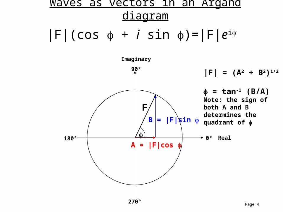
Waves as vectors in an Argand diagram
|F|(cos + i sin )=|F|ei
Real
Imaginary
0°180°
270°
90°
F
A = |F|cos
B = |F|sin
|F| = (A2 + B2)1/2
= tan-1 (B/A)Note: the sign of both A and B determines the quadrant of

Page 5
Two Point Scatterers
2
#1
#2
E
B
Incident radiationis in phase
Radiation scatteredfrom two pointsat angle 2will in general be out of phase
Observe at distance >> spacing of scatterers

Page 6
2
#1 (origin)
#2
x12
l1
l2
x12
ni
ni = unit vector in direction of incident radiation ns
ns = unit vector in direction of scattered radiation
Define unit vectors:
Path length difference l l1 l2 ˆ n s x ˆ n i x ˆ n s ˆ n i x
Phase shift of radiation scattered from #2 relative to that scattered from #1:
2 l
2
ˆ n s ˆ n i x

Page 7
ˆ n s
ˆ n i
s=ˆ n s ˆ n i
Scattering Vector
Ewald sphereradius = 1/
We define the scattering vector s as shown. The tip of s lies on the"Ewald sphere" (this is also called the"sphere of reflection").
Since the scattering angle is 2, the magnitude of the scatteringvector is:
s 2sin( )
In terms of s, the phase shift of radiationscattered from #2, relative to thatscattered from #1, is:
ns
ni
s
x12
2
ˆ n s ˆ n i x
2sx
2
ˆ n s ˆ n i x
2sx

Page 8
For each scatterer, only a fraction of the incident radiation will be scattered; the ratio of scattered to incident radiation is called the "scattering factor" or "scattering power", denoted f.
The contribution of each scatterer to the total scattering amplitude of a group will then include both the scattering factor f (the magnitude of its contribution) and a phase relative to an origin.
E0
f E0
incident scattered
contribution = f ei() length=f
Re
Im
Multiple scatterers - at a given angle 2, see sum of all scattering in that direction
For a group of scatterers, the total scattered wave at a given observation angle is given by the sum of all contributions:
x2
x3
1
2
3
x1origin
F(s) f j
all scatterers j e
i(j) fj
all scatterers j ei(2 sx j )

Page 9
F(s) = | F(s)| ei is called the structure factor
|F(s)| is the amplitude and is the phase of the wave that results from superposition of the scattered waves of the individual atoms in the direction given by s (|s| = 2 sin /).
Real axis
Im. a
xis
f2
f3
f1
F
For electromagnetic radiation, the observed intensity I(s) is given by the absolute square of the amplitude I(s) = F*(s) F(s).

Page 10
Scattering pattern = Fourier transform of the object
The structure factors are the component waves that represent the object. Structure factors at higher angle are higher frequency components, provide more detail.
Object Diffraction pattern Image Fourier transform Fourier transform
Any complex waveform can be built up by superposition of waves of different frequencies(Fourier synthesis), or decomposed into its component frequencies (Fourier analysis).

Page 11
Crystal = motif that repeats in spaceThe repeat unit = UNIT CELL
Diffraction from crystals
The repeat lengths define a lattice
c
b
a
The crystal can be considered as a single motif that is laid down on every lattice point.

Page 12
Scattering from a 1-D lattice of spacing a
a.…. …..
-4 0-3 -2 -1 1 2 3 4n =
There are 2N + 1 identical scatterers. The scattering from the nth scatterer at s is f(s) ei2ns a
N sin[(2N+1) s a]The total scattering from the array is F(s) = f(s) ei2n s a = f(s)
n = -N sin( s a)
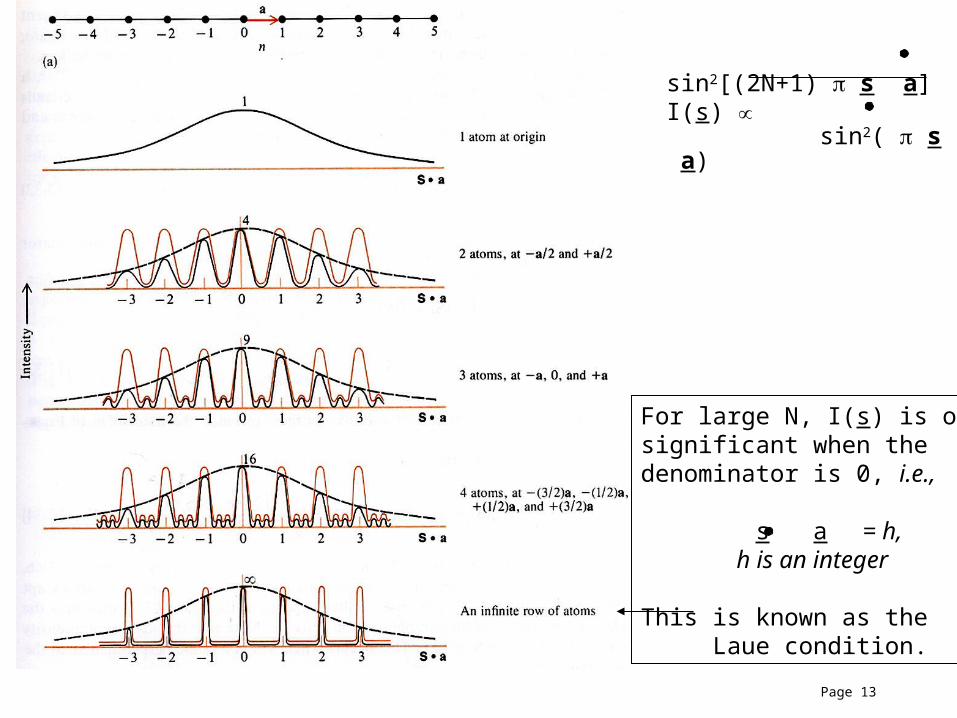
We observe intensity, so for N scatterers the intensity profile is given by
sin2[(2N+1) s a] I(s) sin2( s a)
Page 13
sin2[(2N+1) s a]I(s)
sin2( s a)
For large N, I(s) is onlysignificant when the denominator is 0, i.e.,
s a = h, h is an integer
This is known as the Laue condition.

Page 14
We see diffracted intensity from a lattice of spacing a only when s a = h (projection of s on a). |s| = h / |a| , i.e. see scattering in only in discrete planes perpendicular to a, spaced at integral multiples of 1/a.

Page 15
s lies on planes perpendicular to a, spaced at 1/a s lies on Ewald sphere
We observe intensity only when the reciprocal lattice intersectsthe Ewald sphere (meets both requirements for s)

Page 16
3-d:s a = h s b = k s c = l
Define reciprocal lattice:1. r.l. axis length inversely related to corresponding real axis
a a* = 1 b b* = 1 c c* = 1
2. A r.l. axis is perpendicular to the other two corresponding real axes, e.g., a* is perpendicular to the b, c plane.
3. The distance from the origin to any r.l. point is given by
d* = ha* + kb* + lc*
Laue equations
Tip of s at lattice points

Page 17
Scattering Vectorˆ n s
ˆ n i
s=ˆ n s ˆ n i
radius = 1/
ˆ n s
ˆ n i
radius = 1/
2sin()
nd * Where d* is a reciprocal lattice spacing
=> see scattering where the reciprocal lattice intersects the Ewald sphere
General scattering: s lies on Ewald sphere Single crystal: s defines reciprocal lattice
d*
|s| =

Page 18
Bragg's treatment of diffraction as reflection from planes in the crystal lattice
Scattered waves from parallel planes are in phase and constructively interfere if their path lengths differ by an integral number of wavelengths:
2 d sinn
With d the spacing between planes.
Planes denoted (h,k,l) - integers indicate the number of times that the planes intersect the unit cell edge. The planes contain the scattering centers.
Planes populated with many scatterers give strong scattering.
Finer spacing of planes (larger h, k, l) corresponds to more interatomic detail - higher resolution

Page 19
2sin()
nd * Where d* is a reciprocal lattice spacing|s| =
Rearrange Bragg's Law:2sin()/ =nd
d = spacing of lattice planes
ˆ n s
ˆ n i
radius = 1/
2d*ˆ n s
ˆ n i
radius = 1/
d*n = 0
n = 2
n = 3
n = 1
d* = 1/d
d d/2
= spacing ofr.l. points
The reciprocal lattice points indexed by h, k, l are equivalent to reflection from crystal planes (h k l) in the Bragg treatment, hence they are often called "reflections".

Page 20
There is an inverse relationship between the distances of the real space lattice and the spacing of the reciprocal lattice points.

Page 21
Single molecule would give a continuous scattering pattern
Incidentradiation
Scatteredradiation
Intensity
Scatterin
g angle

Page 22
Intensity
Scatterin
g angle
Scatteredradiation
Incidentradiation
A lattice of identical points acts as a diffraction grating
When a copy of the molecule is placed on each point of the lattice, its continuous transform is multiplied by the lattice transform. This gives a diffraction pattern in which the spacing of spots is determined by the lattice spacing and the intensity is determined by scattering profile of the molecule.
Page 23
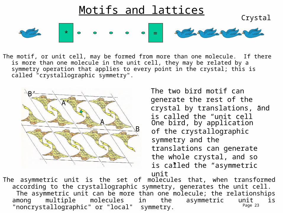
Motifs and latticesCrystal
* =
The motif, or unit cell, may be formed from more than one molecule. If there is more than one molecule in the unit cell, they may be related by a symmetry operation that applies to every point in the crystal; this is called "crystallographic symmetry".
A
A’
B
B’ The two bird motif can generate the rest of the crystal by translations, and is called the “unit cell”
One bird, by application of the crystallographic symmetry and the translations can generate the whole crystal, and so is called the “asymmetric unit”
The asymmetric unit is the set of molecules that, when transformed according to the crystallographic symmetry, generates the unit cell. The asymmetric unit can be more than one molecule; the relationships among multiple molecules in the asymmetric unit is "noncrystallographic" or "local" symmetry.

Page 24
Lattices and space groups• Molecules in the unit cell can be related by various kinds
of symmetry operations. The set of symmetry operations that generate the unit cell from the asymmetric unit is called the space group.
• Enantiomorphic molecules have restricted types of symmetry:
– Rotations
• Pure
- Centering operations
• Screw180 180

Page 25
P C I F
[P]
[P,C][P,C,I,F]
[P,I]
[P][P]
[P,I,F]
Particular types of crystallographic symmetry impose particular constraints on the geometry of the crystal lattice, giving rise to 7 “crystal systems”.

Page 26
Orthorhombic symmetry generated by perpendicular twofold axes.e.g. twofolds about a single point: 222 symmetry
180°
180°
Angles between axes are constrained by symmetry to be 90°.

Page 27
The three perpendicular twofolds constrain the orthorhombic cell to have 90° angles
Hence,a ≠ b ≠ c but = = = 90°
a
b
c

Page 28
Data collection: move crystal so that its associated reciprocal lattice intersects the Ewald sphere.
1. The reciprocal lattice obeys symmetry relationships of the corresponding real lattice.
ˆ n s
ˆ n i
detector
X-ray beam
2. The symmetry of the unit cell contents is present in the scattering pattern. Therefore, it is generally not necessary to measure diffraction data in all scattering directions, as some reflections are equivalent to others by symmetry.

Page 29
Scattering pattern = Fourier transform of the object
The structure factors are the component waves that represent the object. Structure factors at higher angle are higher frequency components, provide more detail.
Object Diffraction pattern Image Fourier transform Fourier transform
Any complex waveform can be built up by superposition of waves of different frequencies(Fourier synthesis), or decomposed into its component frequencies (Fourier analysis).
To reconstruct the image, we need the component structure factors. However , the observed intensity I(s) = F*(s) F(s). When we measure the diffraction pattern, we measure I(s), so we only obtain the amplitude of the structure factor, and lose its phase. This is the central problem in crystallography.

Page 30
Atomic scattering
• A charge which interacts with an electromagnetic wave
experiences a force and oscillates.
• Oscillating (i.e. accelerating) charges act as new sources.
• The atomic scattering factor f describes the scattering given the
arrangement of electrons in the atom (interference
between charges)
• For free electrons, the scattered radiation has a constant phase
shift of 180° relative to the incident radiation

Page 31
Anomalous scattering
Scattering by free electrons: energy (wavelength) invariant; constant phase shift. Real atoms: electrons are not free, but bound in orbitals
-- absorption occurs near energies corresponding to transitions between orbitals-- the scattered radiation experiences a phase shift that is energy dependent
Energy ( = hc/) Scattering angle
f
"Normal" atomic scattering Anomalous scattering
f

Page 32
The atomic scattering factor f can be described by the normal (energy-invariant, treating electrons as free scatterers) and anomalous (energy dependent) scattering. Because of the energy-dependent phase shift, the scattering must now be described as a complex number. The real part of the anomalous scattering is f' , and the imaginary component is f''. Away from the absorption edge, these anomalous "corrections" are generally small, but near the edge they are significant.
Real axis
Im. a
xis
f'fnormal
f''f
Atom at origin Atom at general position in unit cell
Real axis
Im. a
xis
f'
fnormal
f''f

Page 33
Real axis
Im. a
xis
f2
f3
f1
F(h k l)
F(-h -k -l)
f'
f''
f''
f'
F(h k l)
F(-h -k -l)
The f'' component is alwaysadvanced 90°
This means that when anomalousscattering is significant,
|F(hkl)| ≠ |F (-h -k -l)|
Normal scattering:
I(hkl) = I (-h -k -l) or |F(hkl)| = |F(-h -k -l)|
This is called Friedel's law.