paper 8 : harmonics mitigation using active power filter : a technological review
DESCRIPTION
By Zainal Salam, Tan Perng Cheng, Awang Jusoh.TRANSCRIPT

Faculty of Electrical Engineering Universiti Teknologi Malaysia
VOL. 8, NO. 2, 2006, 17‐26 ELEKTRIKA
Harmonics Mitigation Using Active Power Filter: A Technological Review Zainal Salam*, Tan Perng Cheng and Awang Jusoh
Department of Energy Conversion, Faculty of Electrical Engineering, Universiti Teknologi Malaysia, 81310 UTM, Skudai, Johor, Malaysia.
*Corresponding author: [email protected] (Z. Salam), Tel: 607-5535363, Fax: 607-5566272
Abstract: This paper is intended to review the development of active power filter (APF) technologies that are commonly used to mitigate harmonics in utility power lines. This review can also be considered as a “tutorial-type paper” as it provides a holistic coverage of the APF technologies by omitting the tedious details, but without losing the main essence of the subject matter. It is hoped that by this approach, it would be possible to lure more power engineering readers to be involved in this important and growing field. The discussion starts with a brief overview of harmonic distortion problems and their impacts on electric power quality. The operation of common APF topologies, namely the shunt, series and hybrid APFs are described in detail. This is followed by a review on different types of reference signal estimation extraction techniques. In particular, the application of the p-q and extension p-q theorems to extract the reference signals are elaborated, as they are the most commonly found in practical APF systems. Finally, an overview of the APF control strategies is provided. A brief discussion on the APF-solar photovoltaic system is also given. At the end of the paper, important references are cited to assist readers who are interested to explore the subject in greater detail.
Keywords: Active power filter, Harmonics mitigation, Power electronics, Power quality, Voltage source inverter.
1. INTRODUCTION The power quality (PQ) problems in power utility distribution systems are not new, but only recently their effects have gained public awareness. Advances in semiconductor device technology have fuelled a revolution in power electronics over the past decade, and there are indications that this trend will continue [1]. However the power electronics based equipments which include adjustable-speed motor drives, electronic power supplies, DC motor drives, battery chargers, electronic ballasts are responsible for the rise in PQ related problems [2],[3]. These nonlinear loads appear to be prime sources of harmonic distortion in a power distribution system. Harmonic currents produced by nonlinear loads are injected back into power distribution systems through the point of common coupling (PCC). As the harmonic currents pass through the line impedance of the system, harmonic voltages appear, causing distortion at the PCC.
Harmonics have a number of undesirable effects on the distribution system. They fall into two basic categories: short-term and long-term. Short-term effects are usually the most noticeable and are related to excessive voltage distortion. On the other hand, long-term effects often go undetected and are usually related to increased resistive losses or voltage stresses [4]. In addition, the harmonic currents produced by nonlinear loads can interact adversely with a wide range of power system equipment, most notably capacitors, transformers, and motors, causing additional losses, overheating, and overloading. These harmonic currents can also cause interferences
with telecommunication lines and errors in metering devices [2]-[3]. Because of the adverse effects that harmonics have on PQ, Standard has been developed to define a reasonable framework for harmonic control [5]. Its objective is to ensure steady-state harmonic limits that are acceptable by both electric utilities and their customers.
Harmonic distortion in power distribution systems can be suppressed using two approaches namely, passive and active powering. The passive filtering is the simplest conventional solution to mitigate the harmonic distortion [6]-[8]. Although simple, the use passive elements do not always respond correctly to the dynamics of the power distribution systems [9]. Over the years, these passive filters have developed to high level of sophistication. Some even tuned to bypass specific harmonic frequencies.
Conventional passive filters consist of inductance, capacitance, and resistance elements configured and tuned to control harmonics. Figure 2.3 shows common types of passive filters and their configurations. The single-tuned “notch” filter is the most common and economical type of passive filter [8]. The notch filter is connected in shunt with the power distribution system and is series-tuned to present low impedance to a particular harmonic current. Thus, harmonic currents are diverted from their normal flow path through the filter. Another popular type of passive filter is the high-pass filter (HPF) [7]. A HPF will allow a large percentage of all harmonics above its corner frequency to pass through. HPF typically takes on one of the three forms, as shown in Figure 1. The first-order, which is characterised by
17

ZAINAL SALAM, TAN PERNG CHENG, AWANG JUSOH/ ELEKTRIKA, 8(2), 2006, 17‐26
large power losses at fundamental frequency, is rarely used. The second-order HPF is the simplest to apply while providing good filtering action and reduced fundamental frequency losses [9]. The filtering performance of the third-order HPF is superior to that of the second-order HPF. However, it is found that the third-order HPF is not commonly used for low-voltage or medium-voltage applications since the economic, complexity, and reliability factors do not justify them [8].
Figure 1. Common types of passive filters and their configurations
Although simple and least expensive, the passive filter
inherits several shortcomings. The filter components are very bulky because the harmonics that need to be suppressed are usually of the low order [4], [9]. Furthermore the compensation characteristics of these filters are influenced by the source impedance. As such, the filter design is heavily dependent on the power system in which it is connected to [8]. Passive filters are known to cause resonance, thus affecting the stability of the power distribution systems [9]. Frequency variation of the power distribution system and tolerances in components values affect the filtering characteristics. The size of the components become impractical if the frequency variation is large [8], [9]. As the regulatory requirements become more stringent, the passive filters might not be able to meet future revisions of a particular Standard. This may required a retrofit of new filters.
2. ACTIVE POWER FILTERS Remarkable progress in power electronics had spurred interest in APF for harmonic distortion mitigation. The basic principle of APF is to utilise power electronics technologies to produce specific currents components that cancel the harmonic currents components caused by the nonlinear load. Figure 2 shows the components of a typical APF system and their connections. The information regarding the harmonic currents and other system variables are passed to the compensation current/voltage reference signal estimator. The compensation reference signal from the estimator drives the overall system controller. This in turn provides the control for the gating signal generator. The output of the gating signal generator controls the power circuit via a suitable interface. Finally, the power circuit in the generalised block diagram can be connected in parallel, series or parallel/series configurations depending on the interfacing inductor/transformer used.
APFs have a number of advantages over the passive filters. First of all, they can suppress not only the supply current harmonics, but also the reactive currents.
supplyinterfacinginductor/
transformernonlinear Load
power circuit
interface
system variablesdetection
reference signalestimator
overall systemcontroller
gating signalsgenerator
switchingpattern
controleffort
referencesignal
compensatedvariables
Single-tuned 1st-orderHigh-pass
2nd-orderHigh-pass
3rd-orderHigh-pass
L
CR
CR L
R L
C
C
Figure 2. Generalised block diagram for APF
Moreover, unlike passive filters, they do not cause harmful resonances with the power distribution systems. Consequently, the APFs performances are independent on the power distribution system properties [9], [34]. On the other hand, APFs have some drawbacks. Active filtering is a relatively new technology, practically less than four decades old. There is still a need for further research and development to make this technology well established.
An unfavourable but inseparable feature of APF is the necessity of fast switching of high currents in the power circuit of the APF. This results in a high frequency noise that may cause an electromagnetic interference (EMI) in the power distribution systems [34]. APF can be connected in several power circuit configurations as illustrated in the block diagram shown in Figure 3. In general, they are divided into three main categories, namely shunt APF, series APF and hybrid APF.
Figure 3. Subdivision of APF according to power circuit
configurations
2.1 Shunt Active Power Filter This is most important configuration and widely used in active filtering applications [10]-[15], [36]. A shunt APF consists of a controllable voltage or current source. The voltage source inverter (VSI) based shunt APF is by far the most common type used today, due to its well known topology and straight forward installation procedure. Figure 4 shows the principle configuration of a VSI based shunt APF. It consists of a DC-bus capacitor (Cf), power electronic switches and an interfacing inductors (Lf).
C
Load
Load
Load
Load
Active Power Filter
series APF hybrid APFshunt APF
current-sourceinverter
voltage-sourceinverter
shunt APF+
series APF
series APF+
shunt PF
shunt APF+
shunt PF
APF in serieswith
shunt PF
Note:APF: Active power filter, PF: Passive filter
18

ZAINAL SALAM, TAN PERNG CHENG, AWANG JUSOH/ ELEKTRIKA, 8(2), 2006, 17‐26
Shunt APF acts as a current source, compensating the harmonic currents due to nonlinear loads. The operation of shunt APF is based on injection of compensation current which is equals to the distorted current, thus eliminating the original distorted current. This is achieved by “shaping” the compensation current waveform (if), using the VSI switches. The shape of compensation current is obtained by measuring the load current (iL) and subtracting it from a sinusoidal reference. The aim of shunt APF is to obtain a sinusoidal source current (is) using the relationship: fLs ii −=i .
Figure 4. Principle configuration of a VSI based shunt
APF
Suppose the nonlinear load current can be written as the sum of the fundamental current component (iL,f) and the current harmonics (iL,h) according to
hLfLL iii ,, += (1)
then the injected compensation current by the shunt APF should be
(2) hLf ii ,=
the resulting source current is
fLfLs iiii ,=−= (3)
which only contains the fundamental component of the nonlinear load current and thus free from harmonics. Figure 5 shows the ideal source current when the shunt APF performs harmonic filtering of a diode rectifier. The injected shunt APF current completely cancels the current harmonics from the nonlinear load, resulting in a harmonic free source current.
From the nonlinear load current point of view, the shunt APF can be regarded as a varying shunt impedance. The impedance is zero, or at least small, for the harmonic frequencies and infinite in terms of the fundamental frequency. As a result, reduction in the voltage distortion occurs because the harmonic currents flowing through the source impedance are reduced. Shunt APFs have the advantage of carrying only the compensation current plus a small amount of active fundamental current supplied to compensate for system losses. It can also contribute to reactive power compensation. Moreover, it is also possible to connect several shunt APFs in parallel to cater
for higher currents, which makes this type of circuit suitable for a wide range of power ratings [34].
Figure 5. Shunt APF harmonic filtering operation principle
2.2 Series Active Power Filter The series APF is shown in Figure 6. It is connected in series with the distribution line through a matching transformer [38], [39]. VSI is used as the controlled source, thus the principle configuration of series APF is similar to shunt APF, except that the interfacing inductor of shunt APF is replaced with the interfacing transformer.
Figure 6. Principle configuration of a VSI based series
APF The operation principle of series APF is based on
isolation of the harmonics in between the nonlinear load and the source. This is obtained by the injection of harmonic voltages (vf) across the interfacing transformer. The injected harmonic voltages are added/subtracted, to/from the source voltage to maintain a pure sinusoidal voltage waveform across the nonlinear load. The series APF can be thought of as a harmonic isolator as shown in Figure 7. It is controlled in such a way that it presents zero impedance for the fundamental component, but appears as a resistor with high impedance for harmonic frequencies components. That is, no current harmonics can flow from nonlinear load to source, and vice versa.
Series APFs are less common than their rival, i.e. the shunt APF . This is because they have to handle high load currents. The resulting high capacity of load currents will increase their current rating considerably compared with shunt APF, especially in the secondary side of the interfacing transformer. This will increase the
20 40
1
60 t [ms]-1
0
i Li f
i s
-1
0
1
-1
0
1
+-
Cf
VSI
NonlinearLoad
Lf
is
if
AC Source iL
+-
Cf
VSI
NonlinearLoad
is vf
AC Source iL
19
ZAINAL SALAM, TAN PERNG CHENG, AWANG JUSOH/ ELEKTRIKA, 8(2), 2006, 17‐26
(c)
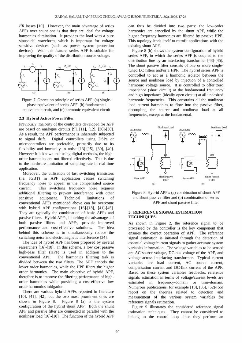
I2R losses [10]. However, the main advantage of series APFs over shunt one is that they are ideal for voltage harmonics elimination. It provides the load with a pure sinusoidal waveform, which is important for voltage sensitive devices (such as power system protection devices). With this feature, series APF is suitable for improving the quality of the distribution source voltage.
(b)
Figure 7. Operation principle of series APF: (a) single-phase equivalent of series APF, (b) fundamental
equivalent circuit, and (c) harmonic equivalent circuit
2.3 Hybrid Active Power Filter Previously, majority of the controllers developed for APF are based on analogue circuits [9], [11], [12], [36]-[38]. As a result, the APF performance is inherently subjected to signal drift. Digital controllers using DSPs or microcontrollers are preferable, primarily due to its flexibility and immunity to noise [13]-[15], [39], [40]. However it is known that using digital methods, the high-order harmonics are not filtered effectively. This is due to the hardware limitation of sampling rate in real-time application.
Moreover, the utilisation of fast switching transistors (i.e. IGBT) in APF application causes switching frequency noise to appear in the compensated source current. This switching frequency noise requires additional filtering to prevent interference with other sensitive equipment. Technical limitations of conventional APFs mentioned above can be overcome with hybrid APF configurations [16]-[18], [41]-[45]. They are typically the combination of basic APFs and passive filters. Hybrid APFs, inheriting the advantages of both passive filters and APFs, provide improved performance and cost-effective solutions. The idea behind this scheme is to simultaneously reduce the switching noise and electromagnetic interference [34].
The idea of hybrid APF has been proposed by several researchers [16]-[18]. In this scheme, a low cost passive high-pass filter (HPF) is used in addition to the conventional APF. The harmonics filtering task is divided between the two filters. The APF cancels the lower order harmonics, while the HPF filters the higher order harmonics. The main objective of hybrid APF, therefore is to improve the filtering performance of high-order harmonics while providing a cost-effective low order harmonics mitigation.
There are various hybrid APFs reported in literature [10], [41], [42], but the two most prominent ones are shown in Figure 8. Figure 8 (a) is the system configuration of the hybrid shunt APF. Both the shunt APF and passive filter are connected in parallel with the nonlinear load [16]-[18]. The function of the hybrid APF
can thus be divided into two parts: the low-order harmonics are cancelled by the shunt APF, while the higher frequency harmonics are filtered by passive HPF. This topology lends itself to retrofit applications with the existing shunt APF.
Figure 8 (b) shows the system configuration of hybrid series APF, in which the series APF is coupled to the distribution line by an interfacing transformer [43]-[45]. The shunt passive filter consists of one or more single-tuned LC filters and/or a HPF. The hybrid series APF is controlled to act as a harmonic isolator between the source and nonlinear load by injection of a controlled harmonic voltage source. It is controlled to offer zero impedance (short circuit) at the fundamental frequency and high impedance (ideally open circuit) at all undesired harmonic frequencies. This constrains all the nonlinear load current harmonics to flow into the passive filter, decoupling the source and nonlinear load at all frequencies, except at the fundamental.
Figure 8. Hybrid APFs: (a) combination of shunt APF and shunt passive filter and (b) combination of series
APF and shunt passive filter
3. REFERENCE SIGNAL ESTIMATION TECHNIQUES As shown in Figure 2, the reference signal to be processed by the controller is the key component that ensures the correct operation of APF. The reference signal estimation is initiated through the detection of essential voltage/current signals to gather accurate system variables information. The voltage variables to be sensed are AC source voltage, DC-bus voltage of the APF, and voltage across interfacing transformer. Typical current variables are load current, AC source current, compensation current and DC-link current of the APF. Based on these system variables feedbacks, reference signals estimation in terms of voltage/current levels are estimated in frequency-domain or time-domain. Numerous publications, for example [10], [35], [52]-[55] report on the theories related to detection and measurement of the various system variables for reference signals estimation.
Figure 9 illustrates the considered reference signal estimation techniques. They cannot be considered to belong to the control loop since they perform an
(a)
+-vf
Zs
vs
+
-
Zf
if
is iL
Zs,f
vs,f
+
-
Zf
if,f
is,f iL,fZeq=0
Zs,h
vs,h
+
-
Zf
if,h
is,h iL,h∞Zeq=
Nonlinear LoadAC Source
Shunt PassiveFilterShunt APF
(a)
AC SourceNonlinear Load
Series APF Shunt PassiveFilter
(b)
20

ZAINAL SALAM, TAN PERNG CHENG, AWANG JUSOH/ ELEKTRIKA, 8(2), 2006, 17‐26
independent task by providing the controller with the required reference for further processing. This section presents the considered reference signal estimation techniques, providing for each of them a short description of their basic features.
Figure 9. Subdivision of reference signal estimation
techniques
3.1 Frequency Domain Approaches Reference signal estimation in frequency-domain is suitable for both single- and three- phase systems. They mainly derived from the principle of Fourier analysis as follows.
3.1.1 Fourier Transform Techniques In principle, Fourier Transform (either conventional or Fast Fourier Transform (FFT)) is applied to the captured voltage/current signal. The harmonic components of the captured voltage/current signal are first separated by eliminating the fundamental component. Inverse Fourier Transform is then applied to estimate the compensation reference signal in time domain [9], [10], [35], [52]-[55].
The main drawback of this technique is the accompanying time delay in system variables sampling and computation of Fourier coefficients. This makes it impractical for real-time application with dynamically varying loads. Therefore, this technique is only suitable for slowly varying load conditions.
In order to make computation much faster, some modifications was proposed and practiced in [56]. In this modified Fourier-series scheme, only the fundamental component of current is calculated and this is used to separate the total harmonic signal from the sampled load-current waveform.
3.2 Time Domain Approaches Time-domain approaches are based on instantaneous estimation of reference signal in the form of either voltage or current signal from distorted and harmonic-polluted voltage and current signals. These approaches are applicable for both single-phase and three-phase systems except for the synchronous-detection theorem [59], [61] and synchronous-reference-frame theorem [13], [15], [17], [18], [40], [43], [44], [50] which can only be adopted for three-phase systems.
3.2.1 Instantaneous Reactive-Power Theorem The instantaneous reactive-power (p-q) theorem is proposed by Akagi et al. [57]. This theorem is based on
0αβ transformation which transforms three-phase voltages and currents into the 0αβ stationary reference frame [14], [45], [58]. From this transformed quantities, the instantaneous active and reactive power of the nonlinear load is calculated, which consists of a DC component and an AC component. The AC component is extracted using HPF and taking inverse transformation to obtain the compensation reference signals in terms of either currents or voltages. This theorem is suitable only for three-phase system and its operation takes place under the assumption that three-phase system voltage waveforms are symmetrical and purely sinusoidal. If this technique is applied to contaminated supplies, the resulting performance is proven to be poor [59].
Reference SignalEstimation Techniques
FrequencyDomain
TimeDomain
Fourier Transform
p-q Theorem
Extension p-q Theorem
Synchronous-Detection Theorem
Synchronous-Reference-FrameTheorem
Sine-Multiplication Theorem
In order to make the p-q theorem applicable for single-phase system, some modifications in the original p-q theorem were proposed and implemented by Dobrucky et al. [27]. Assume that the source voltage ( sv ) and load current ( Li ) of a single-phase system are defined as
)sin(2)( tVtv ss ω= (4)
)sin(2)( θω += tIti LL (5)
After complementing by fictitious imaginary phase (shifted by 90˚), the complemented source voltage ( '
sv )
and load current ( 'Li ) are defined as
)90sin(2)(' o−= tVtv ss ω (6)
)90sin(2)( −+= θωtIti LL' o (7)
the αβ orthogonal co-ordinate system is obtained, whereas
)(tvv s=α and (8) )(' tvv s=β
)(tii L=α and i (9) )(ti 'L=β
Thus, the instantaneous active power of the load can be derived as
ppivivp ~+=⋅+⋅= ββαα (10)
The instantaneous reactive power of the load can be derived as
qqivivq ~+=⋅−⋅= αββα (11)
From the obtained instantaneous active and reactive power, the AC components ( p~ and q~ ) are extracted
21

ZAINAL SALAM, TAN PERNG CHENG, AWANG JUSOH/ ELEKTRIKA, 8(2), 2006, 17‐26
using HPF. The extracted AC components are then used for compensation reference signal estimation.
3.2.2 Extension Instantaneous Reactive-Power Theorem The conventional p-q theorem is revised and extended by Komatsu and Kawabata [26] to make it applicable for three-phase unsymmetrical and distorted voltage system. It differs from the conventional p-q theorem presented in [57]. In extension p-q theorem, the source voltages are shifted by 90° for instantaneous reactive power calculation [24]. Instead of the AC components in conventional p-q theorem, the DC components are extracted using low-pass filters (LPFs) and taking inverse transformation to obtain the compensation reference signals in terms of either currents or voltages. The main advantage of this technique is that it is simpler to find three-phase instantaneous reactive power than the conventional p-q theorem [26].
This technique is also suitable for single-phase APF systems [25], [60]. In order to illustrate the difference between the extension p-q theorem with its former, the basics of extension p-q theorem for single-phase system are presented in this sub-section. Assume that the source voltage ( sv ) and load current ( Li ) of a single-phase system are defined in equation (2.5) and (2.6) respectively. The instantaneous active power of the load can be derived as
pptitvp Ls~)()( +=⋅= (12)
The instantaneous reactive power of the load can be derived as
qqtitvq Ls~)()(' +=⋅= (13)
where )(' tvs denotes the source voltage shifted by . o90The DC components ( qp and ) are extracted from the
derived instantaneous active and reactive power using LPFs. The extracted DC components are then used for compensation reference signal estimation. It is clearly seen that the resulting equations for the instantaneous active and reactive power of the load based on extension p-q theorem are simpler compared with the p-q theorem [27] presented in sub-section 3.2.1.
3.2.3 Synchronous-Detection Theorem Synchronous-detection theorem [59], [61] is very similar to p-q theorem. This technique is suitable only for three-phase system and its operation relies in the fact that the three-phase currents are balanced. It is based on the idea that the APF forces the source current to be sinusoidal and in phase with the source voltage despite the load variations. The average power is calculated and divided equally between the three-phases. The reference signal is then synchronised relative to the source voltage for each phase. Although this technique is easy to implement, it suffers from the fact that it depends to a great extent on the harmonics in the source voltage [10].
3.2.4 Synchronous-Reference-Frame Theorem This theorem relies on the Park’s Transformations to transform the three phase system voltage and current variables into a synchronous rotating frame [13], [15], [17], [18], [40], [43], [44], [50]. The active and reactive components of the three-phase system are represented by the direct and quadrature components respectively. In this theorem, the fundamental components are transformed into DC quantities which can be separated easily through filtering.
This theorem is applicable only to three-phase system. The system is very stable since the controller deals mainly with DC quantities. The computation is instantaneous but incurs time delays in filtering the DC quantities [54].
3.2.5 Sine-Multiplication Theorem This theorem is based on the process of multiplying the nonlinear load current signal by a sine wave of fundamental frequency and integrating the result to calculate the real fundamental component of nonlinear load current [11], [12], [36]. It is applicable for both single- and three- phase systems. The difference between the instantaneous nonlinear load current and this fundamental component is the command current for the APF. Although this technique eliminates the time delay due to low/high-pass filtering, its performance is still slow (for more than one complete mains cycle), due to integration and sampling [54]. This technique is similar to the Fourier Technique. It is, however, differently implemented.
4.0 CONTROL TECHNIQUES FOR ACTIVE POWER FILTER The aim of APF control is to generate appropriate gating signals for the switching transistors based on the estimated compensation reference signals. The performance of an APF is affected significantly by the selection of control techniques [62]. Therefore, the choice and implementation of the control technique is very important for the achievement of a satisfactory APF performance.
A variety of control techniques, such as linear control [9], [11]-[13], [18], [23]-[25], [36], [37], [40], digital deadbeat control [14], [15], [63]-[65], hysteresis control [17], [26], [27], [57], [58], [60], etc., are implemented for the APF applications. Several publications [10], [52], [54], [55], [62] comprehensively report the theories related to APF control techniques. This section briefly describes the considered control techniques and their basic features. 4.1 Linear Control Technique The linear control of APF is accomplished by using a negative-feedback system as shown in Figure 10. In this control scheme, the compensation current ( fi ) or voltage ( fv ) signal is compared with its estimated reference
22
ZAINAL SALAM, TAN PERNG CHENG, AWANG JUSOH/ ELEKTRIKA, 8(2), 2006, 17‐26
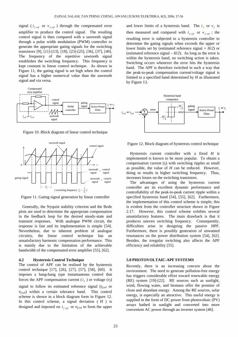
signal ( reffi , or reffv , ) through the compensated error amplifier to produce the control signal. The resulting control signal is then compared with a sawtooth signal through a pulse width modulation (PWM) controller to generate the appropriate gating signals for the switching transistors [9], [11]-[13], [18], [23]-[25], [36], [37], [40]. The frequency of the repetitive sawtooth signal establishes the switching frequency. This frequency is kept constant in linear control technique. As shown in Figure 11, the gating signal is set high when the control signal has a higher numerical value than the sawtooth signal and via versa.
Figure 10. Block diagram of linear control technique
Figure 11. Gating signal generation by linear controller
Generally, the Nyquist stability criterion and the Bode
plots are used to determine the appropriate compensation in the feedback loop for the desired steady-state and transient responses. With analogue PWM circuit, the response is fast and its implementation is simple [54]. Nevertheless, due to inherent problem of analogue circuitry, the linear control technique has an unsatisfactory harmonic compensation performance. This is mainly due to the limitation of the achievable bandwidth of the compensated error amplifier [55], [62].
4.2 Hysteresis Control Technique The control of APF can be realised by the hysteresis control technique [17], [26], [27], [57], [58], [60]. It imposes a bang-bang type instantaneous control that forces the APF compensation current ( fi ) or voltage (vf)
signal to follow its estimated reference signal (if,ref or vf,ref) within a certain tolerance band. This control scheme is shown in a block diagram form in Figure 12. In this control scheme, a signal deviation ( H ) is designed and imposed on reffi , or vf,ref to form the upper
and lower limits of a hysteresis band. The fi or fv is then measured and compared with reffi , or reffv , ; the resulting error is subjected to a hysteresis controller to determine the gating signals when exceeds the upper or lower limits set by (estimated reference signal + H/2) or (estimated reference signal – H/2). As long as the error is within the hysteresis band, no switching action is taken. Switching occurs whenever the error hits the hysteresis band. The APF is therefore switched in such a way that the peak-to-peak compensation current/voltage signal is limited to a specified band determined by H as illustrated by Figure 13.
controlsignal
PWMcontroller
Active PowerFilter
gatingsignal
if,ref or vf,ref
+_
Compensatederror amplifier
if or vf
sawtoothsignal
error
Hysteresis bandcomparator
Active PowerFilter
gatingsignal
if,ref or vf,ref + _
if or vf
∑ error2
H+
2H−
Figure 12. Block diagram of hysteresis control technique sawtooth signalcontrol signal
0 t
gating signal
Ts( switching frequency fs =
1Ts
)
sawtoothsignal
controlsignal<
sawtoothsignal
controlsignal>
Hysteresis current controller with a fixed H is
implemented is known to be more popular. To obtain a compensation current (if) with switching ripples as small as possible, the value of H can be reduced. However, doing so results in higher switching frequency. Thus, increases losses on the switching transistors.
The advantages of using the hysteresis current controller are its excellent dynamic performance and controllability of the peak-to-peak current ripple within a specified hysteresis band [54], [55], [62]. Furthermore, the implementation of this control scheme is simple; this is evident from the controller structure shown in Figure 2.17. However, this control scheme exhibits several unsatisfactory features. The main drawback is that it produces uneven switching frequency. Consequently, difficulties arise in designing the passive HPF. Furthermore, there is possibly generation of unwanted resonances on the power distribution system [54], [62]. Besides, the irregular switching also affects the APF efficiency and reliability [55].
5.0 PHOTOVOLTAIC-APF SYSTEMS Recently, there is an increasing concern about the environment. The need to generate pollution-free energy has triggers considerable effort toward renewable energy (RE) system [19]-[22]. RE sources such as sunlight, wind, flowing water, and biomass offer the promise of clean and abundant energy. Among the RE sources, solar energy, is especially an attractive. This useful energy is supplied in the form of DC power from photovoltaic (PV) arrays bathed in sunlight and converted into more convenient AC power through an inverter system [46].
23

ZAINAL SALAM, TAN PERNG CHENG, AWANG JUSOH/ ELEKTRIKA, 8(2), 2006, 17‐26
Efforts have been made to combine the shunt APF with PV system [23]-[25], [50], [51]. The PV interactive shunt APF system can supply real power from the PV array to loads, and support reactive and harmonic power simultaneously to utilise its utmost installation capacity.
Figure 13. Gating signal generation by hysteresis controller
Generally, the distribution line interactive PV system
extracts power from the PV array, providing current to the distribution line. When the distribution power sources need to provide the peak power to the load, the energy provided by PV array can alleviate the burden of distribution power sources. At night and during no sunlight periods, the power required by the loads is received from the distribution line.
Recently, researchers have spent efforts in developing PV interactive shunt APF systems [23]-[25], [50], [51]. The PV interactive shunt APF can inject PV power into distribution line. In addition, it can support reactive power compensation and filter harmonic currents caused by nonlinear load. Figure 14 illustrates the configuration of a PV interactive shunt APF system which is similar to the standard distribution line interactive PV inverter system. This scheme employs only one inverter to have the reactive power compensation, harmonic currents mitigation, and real power supply functions.
Figure 14. Configuration of a PV interactive shunt APF
system
In the day-time with intensive sunlight, the PV interactive shunt APF system brings all its functions into operation. At night and during no sunlight periods, the power required by the loads is received from the distribution system while the inverter system only provides reactive power compensation and filter harmonic currents. Thus, the utilisation level of the PV interactive shunt APF system is higher than the distribution line interactive PV inverter system.
t
reference signal
actual signal
gating signal
( uneven frequency fs )
H
if or vfif or vf
if,ref or vf,ref
6. CONCLUSION This paper gives an overall view on the development of APF technologies. A brief discussion on the harmonic distortion problems and their impacts on electric PQ are given. The conventional mitigation methods using passive filters are presented first, followed by the improved mitigation methods using APFs. It also reviews different types of reference signal estimation techniques which is an integral part of the APF. An overview of the control strategies for APF is presented. Finally recent efforts in combining the PV system with the shunt APF are discussed briefly.
REFERENCES [1] H. Akagi, “New Trends in Active Filters for Power
Conditioning,” IEEE Trans. on Industry Applications, vol. 32, no. 6, pp. 1312-1322, 1996.
[2] W. E. Kazibwe and M. H. Sendaula. Electric Power Quality Control Techniques. Van Nostrand Reinhold, 1993, New York, USA.
[3] R. C. Dugan, M. F. McGranaghan, S. Santoso and H. W. Beaty. Electrical Power Systems Quality 2nd. ed. McGraw-Hill, 2002, USA.
[4] W. M. Grady and S. Santoso, “Understanding Power System Harmonics,” IEEE Power Engineering Review, vol. 21, no. 11, pp. 8-11, 2001.
[5] Institute of Electrical and Electronics Engineers. Recommended Practices and Requirements for Harmonic Control in Electrical Power Systems. IEEE Standard 519., 1993, USA.
[6] D. A. Gonzalez and J. C. McCall, “Design of Filters to Reduce Harmonic Distortion in Industrial Power Systems,” IEEE Trans. on Industry Applications, vol. IA-23,pp. 504-512, 1987. PCC
AC Source
ElectricalLoad
+
-
Shunt APF
PV Array
NonlinearLoad
[7] A. Ludbrook, “Harmonic Filters for Notch Reduction,” IEEE Trans. on Industry Applications, vol. 24, pp. 947-954, 1988.
[8] J. K. Phipps, “A Transfer Function Approach to Harmonic Filter Design,” IEEE Industry Applications Magazine, vol. 3, no. 2, pp. 68-82, 1997.
[9] J. C. Das, “Passive Filters – Potentialities and Limitations,” IEEE Trans. on Industry Applications, vol. 40, no. 1, pp. 232-241, 2004.
[10] M. El-Habrouk, M. K. Darwish and P. Mehta, “Active Power Filters: A Review,” Proc. IEE Electric Power Applications, vol. 147, no. 5, pp. 403-413, 2000..
[11] H. L. Jou and H. –Y. Wu, “New Single-Phase Active Power Filter,” Proc. IEE Electric Power Applications, vol. 141, no. 3, pp. 129-134, 1994.
24

ZAINAL SALAM, TAN PERNG CHENG, AWANG JUSOH/ ELEKTRIKA, 8(2), 2006, 17‐26
[12] C. Y. Hsu and H. –Y. Wu, “A New Single-Phase Active Power Filter with Reduced Energy-Storage Capacity,” Proc. IEE Electric Power Applications, vol. 143, no. 1, pp. 25-30, 1996.
[13] S. G. Jeong and M. H. Woo, “DSP-Based Active Power Filter with Predictive Current Control,” IEEE Trans. on Industrial Electronics, vol. 44, no. 3, pp. 329-336, 1997.
[14] S. Buso, L. Malesani, P. Mattavelli and R. Veronese, “Design and Fully Digital Control of Parallel Active Power Filters for Thyristor Rectifiers to Comply with IEC-1000-3-2 Standards,” IEEE Trans. on Industry Applications, vol. 34, no. 3, pp. 508-517, 1998.
[15] P. Jintakosonwit, H. Fujita and H. Akagi, “Control and Performance of a Fully-Digital-Controlled Shunt Active Filter for Installation on Power Distribution System,” IEEE Trans. on Power Electronics, vol. 17, no. 1, pp. 132-140, 2002.
[16] S. Fukuda and T. Endoh, “Control Method for a Combined Active Filter System Employing a Current Source Converter and a High Pass Filter,” IEEE Trans. on Industry Applications, vol. 31, no. 3, pp. 590-597, 1995.
[17] S. Khositkasame and S. Sangwongwanich, “Design of Harmonic Current Detector and Stability Analysis of a Hybrid Parallel Active Filter,” Proceedings of the Power Conversion Conference (PCC), Nagaoka, Japan, 1997 pp. 181-186.
[18] M. Routimo, M. Salo and H. Tuusa, “A Novel Control Method for Wideband Harmonic Compensation,” Proceedings of the IEEE International Conference on Power Electronics and Drive Systems (PEDS), Singapore, 2003, pp. 799-804.
[19] K. Hassmann, “Electric Power Generation,” Proc. IEEE, vol. 81, no. 3, pp. 346-354, 1993.
[20] T. J. Hammons, et al., ”Renewable Energy Alternatives for Developed Countries,” IEEE Trans. on Energy Conversion, vol. 15, no. 4, pp. 481-493, 2000.
[21] S. R. Bull, “Renewable Energy Today and Tomorrow,” Proc. IEEE, vol. 89, no. 8, pp. 1216-1226, 2001.
[22] N. M. Maricar, et al., “Photovoltaic Solar Energy Technology Overview for Malaysia Scenario,” Proceedings of the IEEE National Conference on Power and Energy Conference (PECon), Bangi, Malaysia, 2003, pp. 300-305.
[23] S. Kim, G. Yoo and J. Song, “A Bifunctional Utility Connected Photovoltaic System with Power Factor Correction and U.P.S. Facility,” Proceedings of the IEEE Conference on Photovoltaic Specialist, Washington, USA, 1996, pp. 1363-1368.
[24] Y. Komatsu, “Application of the Extension pq Theory to a Mains-Coupled Photovoltaic System,” Proceedings of the Power Conversion Conference (PCC), Osaka, Japan, 2002, pp. 816-821.
[25] T. –F. Wu, C. –L. Shen, C. H. Chang and J. –Y. Chiu, “1/spl phi/ 3W Grid-Connection PV Power Inverter with Partial Active Power Filter,” IEEE Trans. on Aerospace and Electronic Systems, vol. 39, no. 2, pp. 635-646, 2003.
[26] Y. Komatsu and T. Kawabata, “Characteristics of Three Phase Active Power Filter using Extension pq Theory,” Proceedings of the IEEE International Symposium on Industrial Electronics (ISIE), Guimaraes, Portugal, 1997, pp. 302-307.
[27] B. Dobrucky, H. Kim, V. Racek, M. Roch and M. Pokorny, “Single-Phase Power Active Filter and Compensator using Instantaneous Reactive Power Method,” Proceedings of the Power Conversion Conference (PCC), Osaka, Japan, 2002, pp. 167-171.
[28] A. Ghosh and G. Ledwich, Power Quality Enhancement Using Custom Power Devices. Kluwer Academic Publishers, 2002, Massachusetts, USA.
[29] J. Stones and A. Collinson, “Power Quality,” IEE Power Engineering Journal, vol. 15, no. 2, pp. 58-64, 2001.
[30] C. W. Jr. Smith, “Power Systems and Harmonic Factors,” IEEE Potentials, vol. 20, no. 5, pp. 10-12, 2001.
[31] J. C. Balda, et al., “Effects of Harmonics on Equipment,” IEEE Trans. on Power Delivery, vol. 8, no. 2, pp. 672-680, 1993.
[32] K. C. Umeh, A. Mohamed and R. Mohamed, “Comparing the Harmonic Characteristics of Typical Single-Phase Nonlinear Loads,” Proceedings of the IEEE National Conference on Power and Energy (PECon), Bangi, Malaysia, 2003, pp. 383-387.
[33] L. S. Czarnecki, “An Overview of Methods of Harmonic Suppression in Distribution Systems,” Proceedings of the IEEE Power Engineering Society Summer Meeting, Washington, USA, 2000, pp. 800-805.
[34] B. Singh, K. Al-Haddad and A. Chandra, “A Review of Active Filters for Power Quality Improvement,” IEEE Trans. on Industrial Electronics, vol. 46, no. 5, pp. 960-971, 1999.
[35] J. –C. Wu and H. –L. Jou, “Simplified Control Method for the Single-Phase Active Power Filter,” Proc. IEE Electric Power Applications, vol. 143, no. 3, pp. 219-224, 1996.
[36] J. Perez, V. Cardenas, F. Pazos and S. Ramirez, “Voltage Harmonic Cancellation in Single-Phase Systems using a Series Active Filter with Low-Order Controller,” Proceedings of the IEEE International Power Electronics Congress (CIEP), Guadalajara, Mexico, 2002, pp. 270-274.
[37] V. B. Bhavaraju and P. Enjeti, “A Fast Active Power Filter to Correct Line Voltage Sags,” IEEE Trans. on Industrial Electronics, vol. 41, no. 3, pp. 333-338, 1994.
[38] G. Blajszczak, “Direct Method for Voltage Distortion Compensation in Power Networks by Series Converter Filter,” Proc. IEE Electric Power Applications, vol. 142, no. 5, pp. 308-312, 1995.
[39] B. S. Rigby and R. G. Harley, “The Design and Control of an Inverter-Based Series Compensator for Dynamic Performance,” Proceedings of the IEEE Power Engineering Society Summer Meeting, Alberta, Canada, 1999, pp. 1146-1151.
[40] R. Li, A. T. Johns, M. M. Elkateb and F. V. P. Robinson, “Comparative Study of Parallel Hybrid Filters in Resonance Damping,” Proceedings of the
25

ZAINAL SALAM, TAN PERNG CHENG, AWANG JUSOH/ ELEKTRIKA, 8(2), 2006, 17‐26
IEEE International Conference on Electric Power Engineering, Hungary, 1999, pp. 230.
[41] L. Chen and A. Jouanne, “A Comparison and Assessment of Hybrid Filter Topologies and Control Algorithms,” Proceedings of the IEEE Power Electronics Specialists Conference (PESC), Vancouver, Canada, 2001, pp. 565-570.
[42] S. Bhattacharya and D. Divan, “Design and Implementation of a Hybrid Series Active Filter System,” Proceedings of the IEEE Power Electronics Specialists Conference (PESC), Georgia, USA, 1995, pp. 189-195.
[43] S. Bhattacharya and D. Divan, “Synchronous Frame Based Controller Implementation for a Hybrid Series Active Filter System,” Proceedings of the IEEE Industry Applications Conference, Florida, USA, 1995, pp. 2531-2540.
[44] F. Z. Peng, H. Akagi and A. Nabae, “A New Approach to Harmonic Compensation in Power Systems – a Combined System of Shunt Passive and Series Active Filters,” IEEE Trans. on Industry Applications, vol. 26, no. 6, pp. 983-990, 1990.
[45] J. –S. Lai, “Power Electronics Applications in Renewable Energy Systems,” Proceedings of the IEEE Industrial Electronics Society Annual Conference, Virginia, USA, 2003, pp. 3025-3026.
[46] D. C. Martins, R. Demonti and I. Barbi, “Usage of the Solar Energy from the Photovoltaic Panels for the Generation of Electrical Energy,” Proceedings of the IEEE International Telecommunications Energy Conference (INTELEC’99), Copenhagen, Denmark, 1999, pp. 17-3.
[47] H. Dehbone, Nayar, Chem, L. Borle and M. Malengret, “A Solar Photovoltaic In-Line UPS System using Space Vector Modulation Technique,” Proceedings of the IEEE Power Engineering Society Summer Meeting, Vancouver, Canada, 2001. pp. 632-637.
[48] U. Herrmann, H. G. Langer and H. Broeck, “Low Cost DC to AC Converter for Photovoltaic Power Conversion in Residential Applications,” Proceedings of the IEEE Power Electronics Specialist Conference (PESC), Washington, USA, 1993, pp. 588-594.
[49] N. G. Sung, J. D. Lee, B. T. Kim, M. Park and I. K. Yu, “Novel Concept of a PV Power Generation System Adding the Function of Shunt Active Filter,” Proceedings of the IEEE Transmission and Distribution Conference, Yokohama, Japan, 2002, pp. 1658-1663.
[50] S. J. Chiang, K. T. Chang and C. Y. Yen, “Residential Photovoltaic Energy Storage System,” IEEE Trans. on Industrial Electronics, vol. 45, no. 3, pp. 385-394, 1998.
[51] M. El-Habrouk, M. K. Darwish and P. Mehta, “A Survey of Active Filters and Reactive Power Compensation Techniques,” Proceedings of the IEE International Conference on Power Electronics and Variable Speed Drives, London, UK, 2000, pp. 7-12.
[52] W. M. Grady, M. J. Samotyj and A. H. Noyola, “Survey of Active Power Line Conditioning Methodologies,” IEEE Trans. on Power Delivery, vol. 5, no. 3, pp. 1536-1542, 1990.
[53] M. Norman, A. Ahsanul, M. Senan and H. Hashim, “Review of Control Strategies for Power Quality Conditioners,” Proceedings of the IEEE National Conference on Power and Energy Conference (PECon), Kuala Lumpur, Malaysia, 2004, pp. 109-115.
[54] D. –H. Chen and S. –J. Xie, “Review of Control Strategies Applied to Active Power Filters,” Proceedings of the IEEE International Conference on Electric Utility Deregulation, Restructuring and Power Technologies (DRPT), Hong Kong, 2004, pp. 666-670.
[55] M. El-Habrouk and M. K. Darwish, “Design and Implementation of a Modified Fourier Analysis Harmonic Current Computation Technique for Power Active Filters using DSPs,” Proc. IEE Electric Power Applications, vol. 148, no. 1, pp. 21-28, 2001.
[56] H. Akagi, Y. Kanazawa and A. Nabae, “Instantaneous Reactive Power Compensators Comprising of Switching Devices without Energy Storage Components,” IEEE Trans. on Industry Applications, vol. 20, no. 3, pp. 625-630, 1984.
[57] P. L. Leow and A. A. Naziha, “SVM Based Hysteresis Current Controller for a Three Phase Active Power Filter,” Proceedings of the IEEE National Conference on Power and Energy Conference (PECon), Kuala Lumpur, Malaysia, 2004, pp. 132-136.
[58] H. –L. Jou, “Performance Comparison of the Three-Phase Active-Power-Filter Algorithms,” Proc. IEE Generation, Transmission and Distribution, vol. 142, no. 6, pp. 646-652, 1995.
[59] T. –F. Wu, C. –L. Shen, J. –Y. Chiu and C. –C. Chen, “An APF with MAPPT Scheme to Improve Power Quality,” Proceedings of the IEEE International Conference on Electrical and Electronic Technology, Singapore, 2001, pp. 620-626.
[60] C. L. Chen, E. L. Chen and C. L. Huang, “An Active Filter for Unbalanced Three-Phase System using Synchronous Detection Method,” Proceedings of the Power Electronics Specialist Conference (PESC), Taipei, Taiwan, 1994, pp. 1451-1455.
[61] S. Buso, L. Malesani and P. Mattavelli, “Comparison of Current Control Techniques for Active Filter Applications,” IEEE Trans. on Industrial Electronics, vol. 45, no. 5, pp. 722-729, 1998.
[62] L. Malesani, P. Mattavelli and S. Buso, “Dead-Beat Current Control for Active Filters,” Proceedings of the Industrial Electronics Conference (IECON), Aachen, Germany, 1998, pp. 1859-1864.
[63] K. Nishida, Y. Konishi and M. Nakaoka, “Current Control Implementation with Deadbeat Algorithm for Three-Phase Current-Source Active Power Filter,” Proc. IEE Electric Power Applications, vol. 149, no. 4, pp. 275-282, 2002.
[64] K. Nishida, M. Rukonuzzman and M. Nakaoka, “Advanced Current Control Implementation with Robust Deadbeat Algorithm for Shunt Single-Phase Voltage-Source Type Active Power Filter,” Proc. IEE Electric Power Applications, vol. 151, no. 3, pp. 283-288, 2004.
26