paradox spectra spc 319 programming/reference manual
DESCRIPTION
Paradox Spectra SPC-319 900MHz Wireless Module Programming/Reference/Installer manual for system installersTRANSCRIPT

900MHz Wireless Bus Module V1.0SPC-319
Reference & Installation Manual

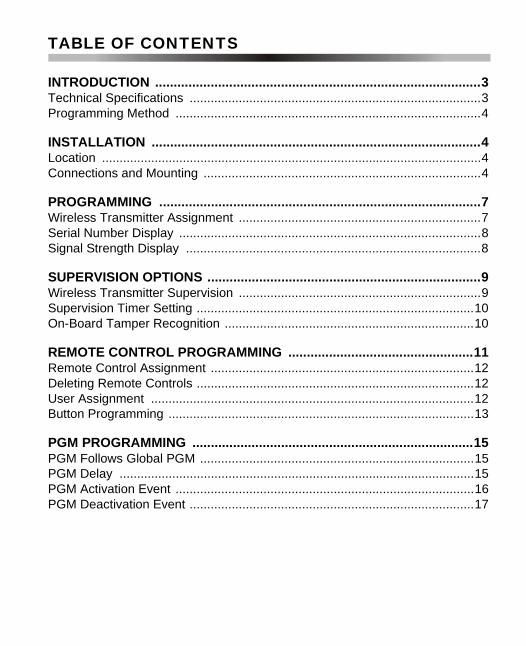
TABLE OF CONTENTS
INTRODUCTION ........................................................................................3Technical Specifications ...................................................................................3Programming Method .......................................................................................4
INSTALLATION .........................................................................................4Location ............................................................................................................4Connections and Mounting ...............................................................................4
PROGRAMMING .......................................................................................7Wireless Transmitter Assignment .....................................................................7Serial Number Display ......................................................................................8Signal Strength Display ....................................................................................8
SUPERVISION OPTIONS ..........................................................................9Wireless Transmitter Supervision .....................................................................9Supervision Timer Setting ...............................................................................10On-Board Tamper Recognition .......................................................................10
REMOTE CONTROL PROGRAMMING ..................................................11Remote Control Assignment ...........................................................................12Deleting Remote Controls ...............................................................................12User Assignment ............................................................................................12Button Programming .......................................................................................13
PGM PROGRAMMING ............................................................................15PGM Follows Global PGM ..............................................................................15PGM Delay .....................................................................................................15PGM Activation Event .....................................................................................16PGM Deactivation Event .................................................................................17


1.0 INTRODUCTION
The SPC-319 Wireless Bus Module allows you to add up to eight fullyprogrammable remote controls and up to eight Liberator Wireless Motion Detectors(LIB-474B) and/or Door Contacts (LIB-400B). The SPC-319 also comes with oneprogrammable 5A output. A second 5A PGM is available as an option.
1.1 TECHNICAL SPECIFICATIONSPower Input: 9-16VDCCurrent Consumption: 70mAFrequency Hopping: @ 902MHz - 928MHzDetector & Door Contact Range:1000m (3280’) for 900MHzRemote Control Range: 30m (100’)Data Rate: 10 KB/sSensitivity: -105dBmDimensions (without antenna): 15cm H x 16cm L x 3cm W
(6” H x 6.5” L x 1.1” W)Operating Temperature: 0°C - 50°C (32°F - 122°F)Operating Humidity: 85%PGM Outputs: 1 (+1 optional)PGM Output Current: 5A relayCompatibility: Spectra control panels (V1.0 or higher):
except 1758 and 1758EXWireless Door Contacts: LIB-400BWireless Motion Detectors: LIB-474B4-button Remote Controls: LIB-349
SPC-319 Wireless Bus Module 3

1.2 PROGRAMMING METHODProgramming the SPC-319 can be accomplished through any keypad connected tothe communication bus.
The SPC-319’s programming guide can be found in the appropriate SpectraProgramming Guide.
2.0 INSTALLATION
2.1 LOCATIONMount the SPC-319 on a wall allowing at least 5cm (2”) around the module to permitadequate ventilation and heat dissipation. Select a site that is not susceptible todrastic temperature changes. Avoid installation near or in the path of strong RFfields (i.e. neon lights, computers), on or near metal objects, circuit breaker boxes,air conditioners, and heater ducts since they may cause interference and reduce itssensitivity. We recommend installing it in a centralized location on the main floor.Avoid installing it in the basement.
2.2 CONNECTIONS AND MOUNTINGFirmly screw the two antennas into the connectors marked "ANT" on the SPC-319 asshown in Figure 2.1 on page 6. Using a drill or screwdriver, punch out the fourmounting holes on the back of the plastic case. Align the six holes of the printedcircuit board with the six pins on the back plastic mounting case and snap into place.If placed correctly, the antennas will lean directly over the grooves in the mountingcase. Connect the “GRN” and “YEL” terminals from SPC-319 to the corresponding“GRN” and “YEL” terminals of the control panel. Connect the “RED” terminal from theSPC-319 to the “AUX+” terminal of the control panel. Connect the “BLK” terminal from
How Do I Enter Programming Mode?1. Press [ENTER].2. Enter your [INSTALLER CODE].3. Enter 3-digit [SECTION] you wish to program.4. Enter required [DATA].
4 Reference & Installation Manual

the SPC-319 to the “AUX-” terminal of the control panel. Please refer to Figure 2.1 onpage 6.
The SPC-319 does not function with 1758 and 1758EX Spectra controlpanels. Do not cut, bend, or alter the antennas. Avoid mounting thereceiver module near or on metal as this may affect its sensitivity.Remove AC power and then remove the battery before adding a busmodule to the system. Do not connect more than one SPC-319 Module tothe control panel.
SPC-319 Wireless Bus Module 5

Figure 2.1: Connecting the SPC-319
6 Reference & Installation Manual

3.0 PROGRAMMING
3.1 WIRELESS TRANSMITTER ASSIGNMENTSECTIONS [601] TO [608]
The first step is to assign each wireless transmitter to a zone in the system. To doso, enter the wireless transmitter’s 6-digit serial number into the appropriate sectionas described below. The serial number can be located on the inside of thetransmitter or you can use the Serial Number Display method (refer to section 3.2 onpage 8) to determine its serial number. Each section from [601] to [608] representsExpansion Inputs 1 through 8 respectively. Each Expansion Input represents aspecific zone in the system depending on the type of Spectra control panel beingused and whether the ATZ option is enabled (refer to the appropriate Spectra controlpanel Programming Guide). Once the transmitters have been assigned, theirassociated zones must be programmed as described in Zone Programming in theSpectra Reference & Installation Manual. You cannot assign more than 8 wirelesstransmitters to the Spectra System.
Do not assign detection devices from different modules to the sameexpansion input. For example, do not assign a wireless transmitter tosection [601], then connect a detection device to input Z1 of the SPC-ZX8.
Section[601] = 6-digit Serial Number = Expansion Input 1
[602] = 6-digit Serial Number = Expansion Input 2
[603] = 6-digit Serial Number = Expansion Input 3
[604] = 6-digit Serial Number = Expansion Input 4
[605] = 6-digit Serial Number = Expansion Input 5
[606] = 6-digit Serial Number = Expansion Input 6
[607] = 6-digit Serial Number = Expansion Input 7
[608] = 6-digit Serial Number = Expansion Input 8
SPC-319 Wireless Bus Module 7

3.2 SERIAL NUMBER DISPLAYSECTION [630]
This feature will display the serial number of any Liberator Motion Detector, DoorContact or Remote Control on any Spectra keypad. To do so:
3.3 SIGNAL STRENGTH DISPLAYSECTIONS [631] TO [638]
This feature allows you to determine whether the SPC-319 will effectively receivesignals from specific wireless motion detectors and door contacts. Each sectionrepresents the signal strength viewer for a specific device. For example, section[631] is the viewer for the device assigned in section [601], and section [638] is theviewer for the device assigned in section [608]. Please note that this feature will onlywork with wireless transmitters that have already been assigned to an ExpansionInput (zone) (refer to section 3.1 on page 7). A reading of 1 is the weakest and areading of 8 is the strongest. An average reading of 3 and up is acceptable.Sometimes moving the transmitter or receiver by a small amount will greatlyincrease the signal reception.
How Do I Display a Transmitter’s Serial Number?1. Enter section [630].2. If it is a Liberator Motion Detector or Door Contact, press its tamper switch.
If it is a Remote Control, press any two buttons on the remote control. Thekeypads will emit a confirmation beep.
3. LED Keypads: The serial number digits will appear one at a time byilluminating the corresponding light. To view the next digit, press the[ENTER] key.LCD Keypads: The first 3 digits of the serial number will appear. Press the[ENTER] key 3 times to view the next 3 digits.
4. Return to step 2 to continue or press [CLEAR] to exit.
8 Reference & Installation Manual

After entering the desired section, ignore the first reading as it will not beaccurate.
4.0 SUPERVISION OPTIONS
4.1 WIRELESS TRANSMITTER SUPERVISIONSECTION [610]: OPTION [1]
The SPC-319 can be programmed to send a Supervision Loss signal to the controlpanel when it has detected that one or more wireless transmitters have notcommunicated any signals for the period defined by the Supervision Timer Setting(refer to section 4.2 on page 10). The control panel will process this signal asdefined by the Wireless Transmitter Supervision Options (refer to the SpectraReference & Installation Manual for more details).
How Do I View a Transmitter’s Signal Strength?
1. Enter the desired [SECTION NUMBER] (631-638).2. LED Keypads: The keypad will illuminate numbers 1 to 8.
LCD Keypads: The keypad will display from 1 to 8 characters on thescreen. For example, in the figure below the LCD screen shows a signalstrength reading of 5.
How Do I Enable or Disable Transmitter Supervision?1. Enter section [610].2. Enable or disable option [1].
Option [1] OFF = Transmitter Supervision disabled (default)Option [1] ON = Transmitter Supervision enabled
SPC-319 Wireless Bus Module 9

4.2 SUPERVISION TIMER SETTINGSECTION [610]: OPTION [2]
If the SPC-319 does not receive a signal from one of its wireless transmitters withinthe period defined here, it can send a Supervision Loss signal to the control panel(refer to section 4.1 on page 9).
The Supervision Timer must be set to the same value as defined by thejumpers on the wireless transmitters.
4.3 ON-BOARD TAMPER RECOGNITIONSECTION [615]
The SPC-319 comes equipped with an on-board tamper switch. This feature willallow a module tamper to report through one of the module’s Expansion Inputs(zone). When a tamper is detected on the module, it will send a Zone Tamper reportcode to the control panel via the communication bus. The Zone Tamper report codewill originate from the zone defined by the Expansion Input (001-008) you haveprogrammed in section [615]. Please note that the corresponding zone must beprogrammed (refer to the Spectra Reference & Installation Manual for more details).
Example: If you program 003 (Expansion Input 3) in section [615] of a Spectra 1728panel and the ATZ feature is enabled, when a tamper occurs on the SPC-319module, the control panel will transmit the Zone Tamper report code as originatingfrom zone 15.
How Do I Set the Supervision Timer?1. Enter section [610].2. Enable or disable option [2].
Option [2] OFF = 12 hours (default)Option [2] ON = 12 minutes
How Do I Set the On-Board Tamper?1. Enter section [615].2. Enter an [INPUT NUMBER] (001-008).
000=Disabled (default)
10 Reference & Installation Manual
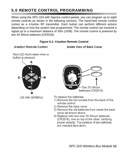
5.0 REMOTE CONTROL PROGRAMMING
When using the SPC-319 with Spectra control panels, you can program up to eightremote controls as shown in the following sections. The hand-held remote controlcomes as a 4-button RF transmitter. Each button can perform different actionsdepending on how the system was programmed. The remote control can transmit asignal up to a maximum distance of 30m (100ft). The remote control is powered bytwo 3V lithium batteries (CR2016).
Figure 5.1: 4-button Remote Control
SPC-319 Wireless Bus Module 11

5.1 REMOTE CONTROL ASSIGNMENTSECTIONS [721] TO [728]
These sections are used to assign up to eight remote controls to the system. Afterassigning a remote control to the system, you must assign a User Access Code anddefine which actions will be performed by the remote control’s buttons as explainedin sections 5.3 and 5.4. Sections [721] to [728] represent remote control numbers 1through 8. Use the Serial Number Display method (refer to section 3.2 on page 8) todetermine the remote control’s serial number.
5.2 DELETING REMOTE CONTROLSSECTION [721] TO [728]
5.3 USER ASSIGNMENTSECTIONS [701] TO [708]
When a user presses a button, the receiver will transmit the assigned User AccessCode to the control panel. This means that the remote control has access to thesame user options and partitions defined by the assigned User Access Code.Assign the User Access Code (001 to 048) into the section corresponding to thedesired remote control, where sections [701] to [708] represent remote controls 1through 8 respectively (refer to section 5.1 on page 12).
How Do I Assign Remote Controls to the System?1. Enter the desired [SECTION NUMBER] (721 to 728).2. Enter the remote control’s 6-digit serial number.
How Do I Delete a Remote Control Assigned to the System?1. Enter the desired [SECTION NUMBER] (721 to 728).2. Enter [000000].
How Do I Assign Remote Controls to Users?1. Enter the desired [SECTION NUMBER] (701-708).2. Enter the User Number (001-048) to be assigned to the remote control.
12 Reference & Installation Manual
5.4 BUTTON PROGRAMMINGSECTIONS [711] TO [718]
Each button or combination of buttons on every remote control can individually beprogrammed to perform specific actions. Each section from [711] to [718]represents remote controls 1 through 8 respectively (refer to section 5.1 on page12). Each section can be programmed with up to 8 digits. Each digit represents abutton or combination of buttons (refer to Table 5.1 on page 14) and each digit canbe any value from 1 to D (refer to Table 5.2 on page 14). If a programmed buttonoption does not work, it may be because the User Access Code assigned to theremote control does not have access to that feature (refer to the Spectra Reference& Installation Manual).
Please note that the User Code assigned to the remote control must havethe same User Options enabled. For example, if you enable the ForceArming button option, you must enable the appropriate Force Arming useroption. Also, if you enable any Panic button options, you must enable thePanic options in the Spectra control panel (refer to the Spectra Reference& Installation Manual).
How Do I Program the remote control buttons?1. Enter the desired [SECTION NUMBER] (711-718).2. Enter the hexadecimal value (1 to D) of the desired options from Table 5.2
on page 14 in the appropriate space (refer to Table 5.1 on page 14). If youdo not wish to program all the buttons or button combinations, simply pressthe [ENTER] button at any time to save and exit.
Note: To delete the hexadecimal values in a particular section (711-718),press the [FORCE] button once for every button.
SPC-319 Wireless Bus Module 13

Table 5.1: Button Programming
Table 5.2: Button Options
Remote Control Button ProgrammingSection
[711] ____/____/____/____/____/____/____/____ A B C D A+B C+D A+C B+D
remote control #1
[712] ____/____/____/____/____/____/____/____ A B C D A+B C+D A+C B+D
remote control #2
[713] ____/____/____/____/____/____/____/____ A B C D A+B C+D A+C B+D
remote control #3
[714] ____/____/____/____/____/____/____/____ A B C D A+B C+D A+C B+D
remote control #4
[715] ____/____/____/____/____/____/____/____ A B C D A+B C+D A+C B+D
remote control #5
[716] ____/____/____/____/____/____/____/____ A B C D A+B C+D A+C B+D
remote control #6
[717] ____/____/____/____/____/____/____/____ A B C D A+B C+D A+C B+D
remote control #7
[718] ____/____/____/____/____/____/____/____ A B C D A+B C+D A+C B+D
remote control #8
[FORCE] = Button Disabled [7] = Regular Arm and Disarm[1] = Regular Arm [8] = Generate a Panic 1 Alarm (Police)[2] = Stay Arm [9] = Generate a Panic 2 Alarm (Medical)[3] = Instant Arm [A] = Generate a Panic 3 Alarm (Fire)[4] = Force Arm [B] = Activates any PGMs that have Event Group
#07 as their Activation Event [5] = Disarm [C] = Activates any PGMs that have Event Group
#08 as their Activation Event[6] = Disarm when there is no alarm
[D] = Activates any PGMs that have Event Group #09 as their Activation Event
14 Reference & Installation Manual

6.0 PGM PROGRAMMING
The SPC-319 provides one programmable 5A relay (PGM). A second 5A PGM isavailable as an option. A PGM is a programmable output that toggles to its oppositestate (i.e. a normally open PGM will close) when a specific event has occurred in thesystem. For example, a PGM can be used to reset smoke detectors, active bells orstrobe lights, open/close garage doors and much more. Refer to Figure 2.1 on page6 to see how to connect the PGM(s).
6.1 PGM FOLLOWS GLOBAL PGMSECTION [610]: OPTIONS [3] AND [4]
Each PGM on the SPC-319 can be programmed to follow the events and/or PGMDelay Timer defined by the Global PGM. This means if the option is enabled, theSPC-319’s PGM will ignore its activation/deactivation events and timer. Instead it willfollow the Global PGM activation and deactivation events programmed in theSpectra control panel. For more information, refer to the Spectra Reference &Installation Manual.
6.2 PGM DELAYSECTIONS [616] AND [617]
After the PGM activation, the PGM will deactivate after the period programmed herehas elapsed. If a delay value from 001 to 255 is programmed, the PGM willdeactivate after the set time elapses and the PGM Deactivation Event set in sections[621] and [623] can be used as a second PGM activation event. If a delay value of
How Do I Enable or Disable the Global PGM?1. Enter section [610].2. Enable or disable options [3] and [4].
Option [3] OFF = PGM1 follows Global PGM disabled (default)Option [3] ON = PGM1 follows Global PGM enabledOption [4] OFF = PGM2 follows Global PGM disabled (default)Option [4] ON = PGM2 follows Global PGM enabled
SPC-319 Wireless Bus Module 15

000 is programmed, the PGM will follow the PGM Deactivation Event set in sections[621] and [623].
6.3 PGM ACTIVATION EVENTSECTIONS [620] AND [622]
This feature allows you to program the SPC-319 to activate its PGM when a specificevent occurs in the system. The PGM will remain in its active state until theprogrammed PGM Deactivation Event occurs (refer to section 6.4 on page 17) orwhen the PGM Delay period has elapsed (refer to section 6.2 on page 15).
Also, refer to section 6.1 on page 15.
How Do I Set the PGM Delay?1. Enter the desired [SECTION NUMBER].
PGM1 = [616]PGM2 = [617]
2. Enter a delay value (001-255) in seconds.default = 5 seconds000 = PGM follows deactivation event (refer to 6.4)
How Do I Program the PGM Activation Event?1. Enter the desired [SECTION NUMBER].
PGM1 = [620]PGM2 = [622]
2. Enter the Event Group # (refer to Table 6.1 on page 18).3. Enter the Sub-Group # (refer to Table 6.1 on page 18).4. Enter the Partition # (refer to Table 6.1 on page 18).
16 Reference & Installation Manual

6.4 PGM DEACTIVATION EVENTSECTIONS [621] AND [623]
After PGM activation (refer to section 6.3 on page 16), the PGM will return to itsnormal state (deactivate) when the programmed PGM Deactivation Event occurs.Instead of deactivating the PGM on the occurrence of a specific event, the PGM candeactivate after a programmed period has elapsed (refer to section 6.2 on page 15).
If a PGM’s Delay is programmed (refer to section 6.2 on page 15), thecorresponding deactivation event can be used as a second activationevent. Also, refer to section 6.1 on page 15.
How Do I Program the PGM Deactivation Event?1. Enter the desired [SECTION NUMBER]:
PGM1 = [621]PGM2 = [623]
2. Enter the Event Group # (refer to Table 6.1 on page 18).3. Enter the Sub-Group # (refer to Table 6.1 on page 18).4. Enter the Partition # (refer to Table 6.1 on page 18).
SPC-319 Wireless Bus Module 17

Table 6.1: PGM Table
18 Reference & Installation Manual

WARRANTYThe Seller warrants its products to be free from defects in materials andworkmanship under normal use for a period of one year. Except as specificallystated herein, all express or implied warranties whatsoever, statutory or otherwise,including without limitation, any implied warranty of merchantability and fitness for aparticular purpose, are expressly excluded. Because Seller does not install orconnect the products and because the products may be used in conjunction withproducts not manufactured by Seller, Seller cannot guarantee the performance ofthe security system. Seller obligation and liability under this warranty is expresslylimited to repairing or replacing, at Seller's option, any product not meeting thespecifications. In no event shall the Seller be liable to the buyer or any other personfor any loss or damages whether direct or indirect or consequential or incidental,including without limitation, any damages for lost profits, stolen goods or claims byany other party caused by defective goods or otherwise arising from the improper,incorrect or otherwise faulty installation or use of the merchandise sold.
SPC-319 Wireless Bus Module 19

NOTES


