part 1 – understanding the landfill gas resource … · 19399 (6) 6 conestoga-rovers &...
TRANSCRIPT

19399 (6) 6 CONESTOGA-ROVERS & ASSOCIATES
PART 1 – UNDERSTANDING THE LANDFILLGAS RESOURCE AND POTENTIALAPPLICATIONS
2
Landfill Gas – Understanding the Resource
2.1 LFG Generation and Generation Factors
LFG is generated as a result of physical, chemical, and microbial processes occurringwithin the refuse. Due to the organic nature of most waste, it is the microbial processesthat govern the gas generation process (Christensen, 1989). These processes are sensitiveto their environment and therefore, there are a number of natural and man-madeconditions, which will affect the microbial population and thus, the LFG production rate.Short-term studies done on full-size landfills, using data from LFG extraction tests,indicate a range of LFG production between 0.05 and 0.40 m3 of LFG per kilogram ofwaste placed into a landfill (Ham, 1989). The mass of waste accounts for both solidmaterials (75-80% by mass) and moisture (20-25% by mass). This range is a function ofthe organic content of the waste that is placed into the landfill. The range in LFGproduction values may at first glance not appear to be large. However, using thepopulation base in LAC and the fuel value of the LFG, the annual quantity of LFG fuel isequivalent to tens of millions of cubic metres of natural gas each year. Typical pipelinegrade natural gas has approximately double the heating value or fuel content of a typicalLFG.

7 Landfill Gas – Understanding the Resource
Waste composition is the most important factor in assessing the LFG generation potentialof a site. The maximum potential volume of LFG is dependent on the quantity and typeof organic content within the waste mass (Environment Canada, 1996) since thedecomposing organic wastes are the source for all LFG produced. Other factors thatinfluence the rate of LFG production include moisture content; nutrient content; bacterialcontent; pH level; temperature; and the site-specific design and operations plans. Wastesproduced in LAC typically have higher organic content and moisture content than mostNorth American or European waste and therefore would be expected to generate LFG atequivalent or higher rates.
Moisture is the primary limiting factor in the rate of waste decomposition (McBean etal., 1995; Reinhart, 1996). The moisture conditions within the landfill are a function ofmany factors. Landfills are typically constructed and filled in sequential layered pattern.This factor is important in understanding how moisture moves into and through thewaste. The layering effect tends to result in substantially different flow characteristics forthe movement of leachate and infiltration water into the landfill. Controlling the moisturecontent and other factors which influence the microbial population that produces LFGcan have a great impact on the percentage of potential total LFG that is produced, and therate at which it is produced. It is possible to somewhat control the rate of LFGproduction through engineered waste management systems. Conventional sanitarylandfills as practiced in North America in the 1970s and 80s are generally referred to as"dry tombs" because the approach taken in designing them was to minimize watercontacting the waste with a view toward minimizing excursions of the resulting leachateinto the groundwater. However, this practice also limits the rate of anaerobic activitywithin the waste. The current trend is towards Landfill Bioreactor Technology (LBT)systems, which augment the amount of water contacting the waste, to rapidly stabilize thewastes. This technique can produce large initial LFG generation rates while decreasingtheir rate of generation sharply after a few years.
For the purpose of an initial site characterization, LFG production can be simplified as afunction of the size and age of the waste volume, waste type, and moisture content. Thevolume of greenhouse gases released is directly proportional to the LFG-generatingpotential. It is also relevant to other potential impacts such as odor complaints andhazardous situations. In general, the more gas that is produced, the higher the likelihoodthat health, safety and odor nuisance issues will be raised, and equally importantly, thatfor economically feasible LFG utilization to exist.
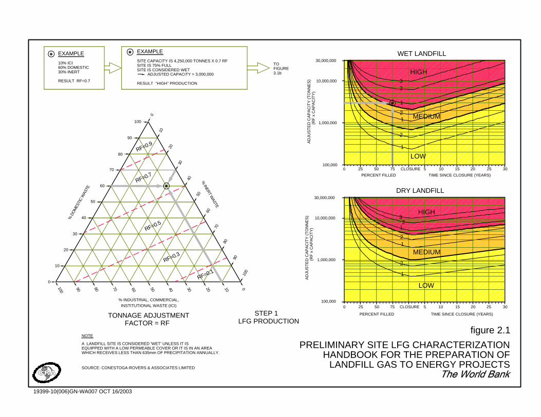
Figure 2.1 provides a method of characterizing a site based on its LFG productionpotential. The first step is to determine the tonnage adjustment factor based on wastecomposition. This correction factor accounts for the proportion of inert wastes in thelandfill, which will not produce LFG, and the proportion ofindustrial/commercial/institutional (ICI) wastes in the landfill that will produce less LFGthan typical domestic wastes. The adjustment factor is determined from the trianglediagram shown in Figure 2.1 based on the proportion of waste types that are in place or
1,000,000
30,000,000
10,000,000
100,000
1,000,000
10,000,000
100,000
30,000,000
INSTITUTIONAL WASTE (ICI)% INDUSTRIAL, COMMERCIAL,
TONNAGE ADJUSTMENTFACTOR = RF
WHICH RECEIVES LESS THAN 635mm OF PRECIPITATION ANNUALLY.EQUIPPED WITH A LOW PERMEABLE COVER OR IT IS IN AN AREAA LANDFILL SITE IS CONSIDERED 'WET' UNLESS IT IS
NOTE
LFG PRODUCTIONSTEP 1
AD
JUS
TE
D C
AP
AC
ITY
(TO
NN
ES
)(R
F x
CA
PA
CIT
Y)
(RF
x C
AP
AC
ITY
)A
DJU
ST
ED
CA
PA
CIT
Y (T
ON
NE
S)
FIGURE
PERCENT FILLED
0 25 50 75 CLOSURE
TIME SINCE CLOSURE (YEARS)
105 15 2520 30
LOW
MEDIUM
HIGH
CLOSURE
DRY LANDFILL
1
2
12
PERCENT FILLED
0 25
3
12
50 75
TIME SINCE CLOSURE (YEARS)
105 15 2520 30
LOW
MEDIUM
HIGH
WET LANDFILL
1
2
21
1
23
30RF=0.7
0
30
80100
90
20
10
70 60
% D
OM
ESTI
C W
ASTE
40
50
60
70
90
3050 40
RF=0.3
RF=0.1
20 10
80
40
RF=0.5
% INERT W
ASTE
60
70
50
0
100
RESULT "HIGH" PRODUCTION
SITE IS CONSIDERED WETSITE IS 75% FULLSITE CAPACITY IS 4,250,000 TONNES X 0.7 RF
EXAMPLE
RF=0.9
80
90
100
60% DOMESTIC30% INERT
RESULT RF=0.7
10% ICI
EXAMPLE
10
20
0
ADJUSTED CAPACITY = 3,000,000 3.1b
TO
SOURCE: CONESTOGA-ROVERS & ASSOCIATES LIMITED
figure 2.1
PRELIMINARY SITE LFG CHARACTERIZATIONHANDBOOK FOR THE PREPARATION OF
LANDFILL GAS TO ENERGY PROJECTS
19399-10(006)GN-WA007 OCT 16/2003

9 Landfill Gas – Understanding the Resource
will be accepted at the landfill. The landfill capacity is multiplied by the tonnageadjustment factor to determine the adjusted site capacity.
The landfill is then classified as dry or wet. A dry landfill will decompose more slowlythan a wet landfill and hence the LFG production rate will be lower, and the productiontime will be longer. Some of the factors that influence the moisture content of a landfillinclude precipitation and temperature at the site, type of landfill cover, condition of cover(i.e., slope, integrity), type of leachate collection system, and type of landfill base ornatural liner. The classification of the site as dry or wet is mainly a function of theamount of precipitation that infiltrates into the waste mass. A conservative approach toclassifying a site as wet or dry based on the average annual rainfall. A landfill where asignificant portion of the waste is located within a groundwater/leachate mound shouldalso be considered a wet site. For general discussion within this Handbook, sites locatedin areas with: less than 500 mm/year will be classified as relatively dry sites; more than500 but less than 1000 mm/year as relatively wet sites; and sites located in areas withmore than 1000 mm/year as wet sites. Most LAC landfills are considered to be relativelywet or wet sites. Further discussion regarding the importance of this aspect of LAC siteswill be provided with the modeling discussions and the applicable parameterassignments.
The adjusted site capacity is located on the left axis of the wet or dry landfill chart. Thisaddresses the effect that the size of the site (small, medium, large) has on gas production.The current status of site filling is located on the bottom axis. This is defined asthe percentage that the site is filled or the number of years since closure of the site. Thisaddresses the age of the site.
LFG production is determined by the intersection of the adjusted site capacity and thecurrent filling status. LFG production is categorized as "high", "medium" or "low". Eachcategory is delineated by numbers, which indicate an increasing level of severity withinthe category. The maximum LFG production typically occurs within two years of siteclosure if the site has had a fairly uniform annual filling schedule. It is important toconsider future LFG production potential in assessing and planning the need for LFGcontrols. Figure 2.1 demonstrates that a site's LFG production increases as it is filled,and then slowly declines after site closure.
Other issues related to the production of LFG, which are of concern, include the LFGsubsurface migration hazard and the impact of LFG on air quality.
The primary factors that influence the distance gas migrates from the wastes into adjacentsoils are the permeability of the soil adjacent to the landfill and the type of ground surfacecover around the landfill. Generally, the greater the permeability of the soil adjacent tothe landfill, the greater the possible migration distance. The water content of the soil hasan important effect on its permeability with respect to LFG flow. As the water contentincreases, the effective soil or waste transmissivity to gas flow decreases. In addition, thetype of ground surface cover affects the venting of LFG that can escape to theatmosphere. Frozen or paved ground surfaces limit venting of gas to the atmosphere and
10 Landfill Gas – Understanding the Resource
hence increase the potential migration distance. A landfill liner can greatly reduce thepotential for subsurface migration. The presence of heterogeneous soils around the siteor sewers and other buried utility service will increase the potential migration distancealong those corridors. LFG can migrate a significant distance from the landfill in sewersor sewer bedding. When evaluating the potential for subsurface migration from a sitethese factors should be considered.
The primary determinants of air quality impacts are the quantity of LFG emitted to theatmosphere, the concentration of trace gas compounds in the LFG, the proximity of thereceptor to the site and meteorological conditions.
2.2 The Scholl-Canyon Model
Mathematical models are a useful and economical tool for estimating the LFG generationpotential at the site. The results of the model can be used to assess the potential forhazardous LFG emissions/migration, and for assessing the feasibility of the LFGmanagement project.
There are numerous models available to calculate LFG production. All of these modelscan be used to develop an LFG generation curve that predicts the gas generation overtime. The total gas yield and rate at which the gases are generated can vary somewhatwith the different models but the most important input parameter that is common to allmodels is the quantity of decomposable waste that is assumed. The other inputparameters can vary depending on the model used, and are influenced by a number ofvariables including those factors influencing LFG generation, uncertainties in theavailable information for the site, and how the management of LFG extraction affectsLFG generation by inducing any air infiltration. Another important factor is the assumedlag time between the placement of waste and the beginning of the anaerobicdecomposition or methanogenic phase within the waste mass. (Augenstein, 1991.)
The heterogeneous and time-variable nature of all landfills lends an inherent difficultywith collecting accurate data from a site without a large ongoing cost outlay. Any modeloutput is only as good as the input data and often there are very broad assumptionsnecessary with respect to estimating waste quantities and types. Therefore, it isappropriate to use a simple model, which employs fewer parameters that can be morereasonably assigned according to specific site conditions. The predictive success of anymodel is dependent mostly on the degree of accuracy needed, the reliability of the inputdata, the experience of the individual analyzing the data, and the degree of similaritybetween the subject site and other sites which have been successfully modeled. (Zison,1990.)
All models used for determining the estimated LFG production rate of the site should besubject to a thorough sensitivity analysis to determine a range of potential outcomes andanalyze which parameters have the greatest influence on LFG production values.Identification of sensitive parameters can lead to directed data collection and futureimprovement in LFG production predictions. Given the heterogeneous nature of the
11 Landfill Gas – Understanding the Resource
conditions within the landfill and the typical limitations in the input data that is mostoften available for a candidate site, it is recommended that a range of values and asensitivity assessment be established for the LFG generation assessment. Using theupper and lower bounds of a LFG generation versus time profile based on the likelyconditions within the landfill, it is possible to assign values and design inputs that aresuitable for use in assessing the potential for a site and any risk factors that may beapplicable.
First-order kinetic models are frequently used to estimate the production of methane overthe life of a landfill. These models are tailored to specific landfills by a number ofassumptions about conditions at the site. The empirical, first-order decay model mostwidely accepted and used by industry and regulatory agencies, including the U.S. EPA, isthe relatively simple and straightforward Scholl Canyon Model. This model is based onthe assumption that there is a constant fraction of biodegradable material in the landfillper unit of time. The first-order equation is given below:
QCH4i = k * Lo * mi * e-kt [1]
QCH4i = methane produced in year i from the ith section of waste
k = methane generation constant
Lo = methane generation potential
mi = waste mass disposed of in year i
ti = years after closure
It is typical practice to assume that the LFG generated consists of fifty percent methaneand fifty percent carbon dioxide so that the total LFG produced is equal to twice thequantity of methane calculated from Equation [1].
Equation [1] is the basis for the U.S. EPA's LFG Emissions Model (LandGEM), which isavailable from the United States Environmental Protection Agency (U.S. EPA) website(http://www.epa.gov/ttn/atw/landfill/landflpg.html). The Scholl Canyon Model predictsLFG production over time as a function of the LFG generation constant (k), the methanegeneration potential (L0), and the historic waste filling records and future wasteprojections at a site. The U.S. EPA assigns default values for each of these parametersfor a conservative preliminary site assessment. However, these input parameters must beselected with knowledge of the specific site conditions and geographic location. In LAC,differences in the organic content of the waste, the presence of moisture, or the level towhich the waste is compacted will vary and in most cases increase the potential for LFGgeneration from that typically found in the North America and Europe. This model hasbeen selected for use in this Handbook not because it is the only available model, or eventhe best model available. However, the Scholl Canyon Model: is adequate for thepurpose intended; is the most commonly employed and accepted model in North andSouth America; and has the best available data base for sites in LAC. The Scholl CanyonModel is also simple to understand and apply, and is generally accepted by those
12 Landfill Gas – Understanding the Resource
financing agencies and institutions that are interested in supporting these types of projectsin North America and LAC.
BOX 1: IMPORTANCE OF LFG GENERATION MODELING & ASSESSMENTOF FUEL RESOURCE POTENTIAL
There are 2 major aspects to the LFG assessment. Firstly it must be estimated how muchLFG there is being produced at a landfill. Secondly, but much more important, it isnecessary to assess what proportion of the LFG can reasonably and reliably be collectedover the long life of a project (>20 years).
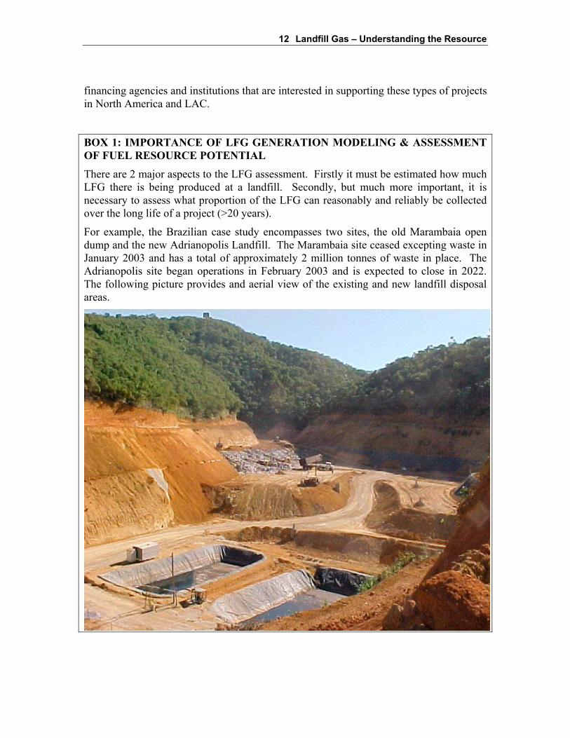
For example, the Brazilian case study encompasses two sites, the old Marambaia opendump and the new Adrianopolis Landfill. The Marambaia site ceased excepting waste inJanuary 2003 and has a total of approximately 2 million tonnes of waste in place. TheAdrianopolis site began operations in February 2003 and is expected to close in 2022.The following picture provides and aerial view of the existing and new landfill disposalareas.
13 Landfill Gas – Understanding the Resource
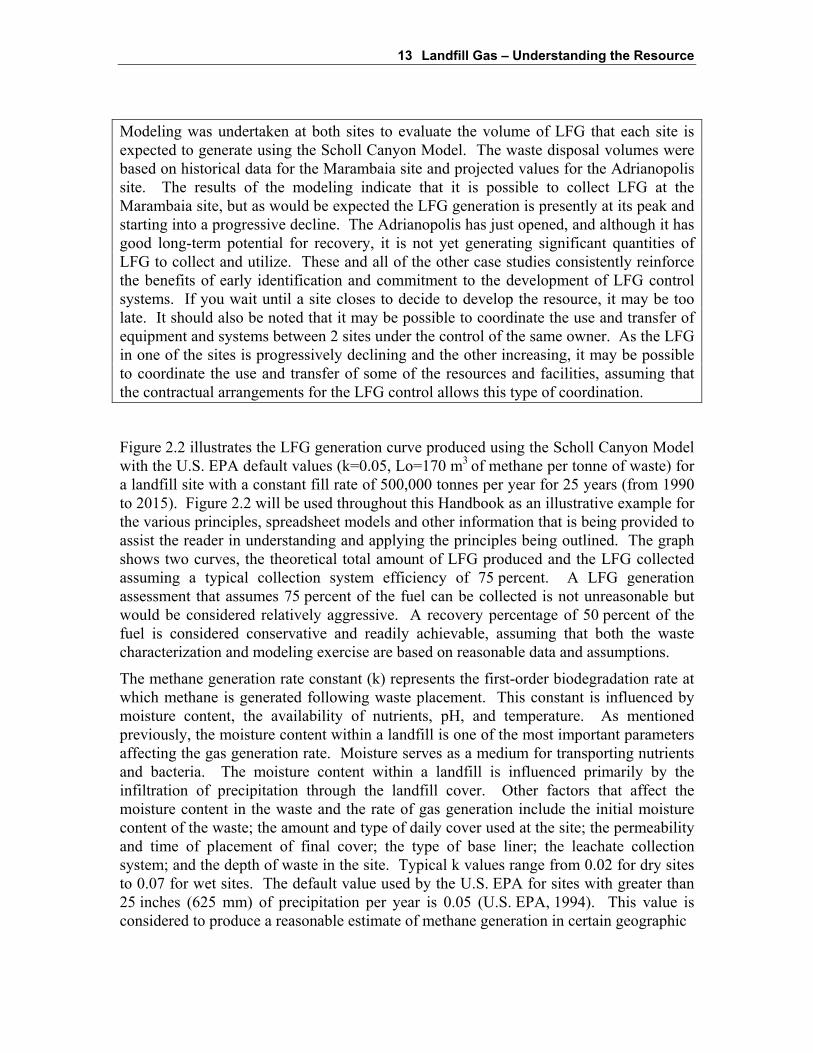
Modeling was undertaken at both sites to evaluate the volume of LFG that each site isexpected to generate using the Scholl Canyon Model. The waste disposal volumes werebased on historical data for the Marambaia site and projected values for the Adrianopolissite. The results of the modeling indicate that it is possible to collect LFG at theMarambaia site, but as would be expected the LFG generation is presently at its peak andstarting into a progressive decline. The Adrianopolis has just opened, and although it hasgood long-term potential for recovery, it is not yet generating significant quantities ofLFG to collect and utilize. These and all of the other case studies consistently reinforcethe benefits of early identification and commitment to the development of LFG controlsystems. If you wait until a site closes to decide to develop the resource, it may be toolate. It should also be noted that it may be possible to coordinate the use and transfer ofequipment and systems between 2 sites under the control of the same owner. As the LFGin one of the sites is progressively declining and the other increasing, it may be possibleto coordinate the use and transfer of some of the resources and facilities, assuming thatthe contractual arrangements for the LFG control allows this type of coordination.
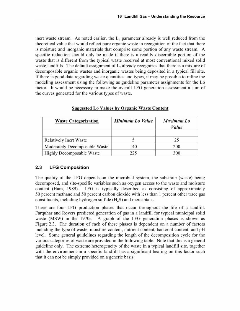
Figure 2.2 illustrates the LFG generation curve produced using the Scholl Canyon Modelwith the U.S. EPA default values (k=0.05, Lo=170 m3 of methane per tonne of waste) fora landfill site with a constant fill rate of 500,000 tonnes per year for 25 years (from 1990to 2015). Figure 2.2 will be used throughout this Handbook as an illustrative example forthe various principles, spreadsheet models and other information that is being provided toassist the reader in understanding and applying the principles being outlined. The graphshows two curves, the theoretical total amount of LFG produced and the LFG collectedassuming a typical collection system efficiency of 75 percent. A LFG generationassessment that assumes 75 percent of the fuel can be collected is not unreasonable butwould be considered relatively aggressive. A recovery percentage of 50 percent of thefuel is considered conservative and readily achievable, assuming that both the wastecharacterization and modeling exercise are based on reasonable data and assumptions.
The methane generation rate constant (k) represents the first-order biodegradation rate atwhich methane is generated following waste placement. This constant is influenced bymoisture content, the availability of nutrients, pH, and temperature. As mentionedpreviously, the moisture content within a landfill is one of the most important parametersaffecting the gas generation rate. Moisture serves as a medium for transporting nutrientsand bacteria. The moisture content within a landfill is influenced primarily by theinfiltration of precipitation through the landfill cover. Other factors that affect themoisture content in the waste and the rate of gas generation include the initial moisturecontent of the waste; the amount and type of daily cover used at the site; the permeabilityand time of placement of final cover; the type of base liner; the leachate collectionsystem; and the depth of waste in the site. Typical k values range from 0.02 for dry sitesto 0.07 for wet sites. The default value used by the U.S. EPA for sites with greater than25 inches (625 mm) of precipitation per year is 0.05 (U.S. EPA, 1994). This value isconsidered to produce a reasonable estimate of methane generation in certain geographic

figure 2.2
EXAMPLE LFG GENERATION CURVESHANDBOOK FOR THE PREPARATION OF LANDFILL GAS TO ENERGY PROJECTS
The World Bank
0
20,000,000
40,000,000
60,000,000
80,000,000
100,000,000
120,000,000
140,000,000
1990 2000 2010 2020 2030 2040 2050 2060Years
An
nu
al L
FG P
rod
uct
ion
(m3 /y
r)
0
1,000
2,000
3,000
4,000
5,000
6,000
7,000
8,000
9,000
Average A
nn
ual L
FG Flow
(cfm)
Theoretical LFG Generation Curve
Recoverable LFG Curve

15 Landfill Gas – Understanding the Resource
regions and under certain site conditions. The following table presents suggested rangesand recommended parameter assignment for the rate constant.
Suggested k Value Ranges for Corresponding Annual Precipitation
Annual Precipitation Range of k ValuesRelatively Inert Moderately
DecomposableHighly
Decomposable<250 mm 0.01 0.02 0.03
>250 to <500 mm 0.01 0.03 0.05>500 to <1000 mm 0.02 0.05 0.08
>1000 mm 0.02 0.06 0.09
The methane generation potential (Lo) represents the total yield of methane (m3 ofmethane per tonne of waste). The Lo value is dependent on the composition of the waste,and in particular, the fraction of organic matter present. The Lo value is estimated basedon the carbon content of the waste, the biodegradable carbon fraction, and astoichiometric conversion factor. Typical values for this parameter range from 125 m3 ofmethane/tonne of waste to 310 m3 of methane/tonne of waste. Increased compaction ofthe waste has no direct effect on the Lo parameter. However, compaction and density ofwaste do have a direct bearing on the mass of waste in a given volume, and therefore onthe potential LFG quantity that can be produced over time, as well as the performancecharacteristics of the systems that will be necessary to collect the LFG.
There has also been a perception that as recycling and composting programs increase andimprove, more organic material, such as food waste and paper, may be diverted from thelandfill reducing the quantity of LFG produced. However, recycling initiatives have hadmore success to date at removing inorganic materials from the waste stream, in bothdeveloped and developing countries. As a consequence, typical practice has not seen theapplicable Lo value decreased significantly. The U.S. EPA uses a default Lo value of170 m3 of methane/tonne of waste. (U.S. EPA, 1994). The model user may increase ordecrease the Lo to reflect specific knowledge of the waste characterization with eitherhigher or lower organic waste contents. The amount (in tonnes) of typical wastelandfilled in a particular year is represented by "m" in the Scholl Canyon Model equation.In landfills where there are good data indicating that there is a significant portion of thewaste that is inert (will not decompose) such as construction and demolition debris, thisparameter could be reduced to represent only the amount of waste that is not inert.However, in many cases there is insufficient data to determine the percentage of thewaste that is inert.
It is only recommended that the Lo parameter be reduced or the quantity of contributingwaste be decreased if there is clear and concise data quantifying the inert or relatively
16 Landfill Gas – Understanding the Resource
inert waste stream. As noted earlier, the Lo parameter already is well reduced from thetheoretical value that would reflect pure organic waste in recognition of the fact that thereis moisture and inorganic materials that comprise some portion of any waste stream. Aspecific reduction should only be made if there is a readily discernible portion of thewaste that is different from the typical waste received at most conventional mixed solidwaste landfills. The default assignment of Lo already recognizes that there is a mixture ofdecomposable organic wastes and inorganic wastes being deposited in a typical fill site.If there is good data regarding waste quantities and types, it may be possible to refine themodeling assessment using the following as guideline parameter assignments for the Lofactor. It would be necessary to make the overall LFG generation assessment a sum ofthe curves generated for the various types of waste.
Suggested Lo Values by Organic Waste Content
Waste Categorization Minimum Lo Value Maximum LoValue
Relatively Inert Waste 5 25Moderately Decomposable Waste 140 200Highly Decomposable Waste 225 300
2.3 LFG Composition
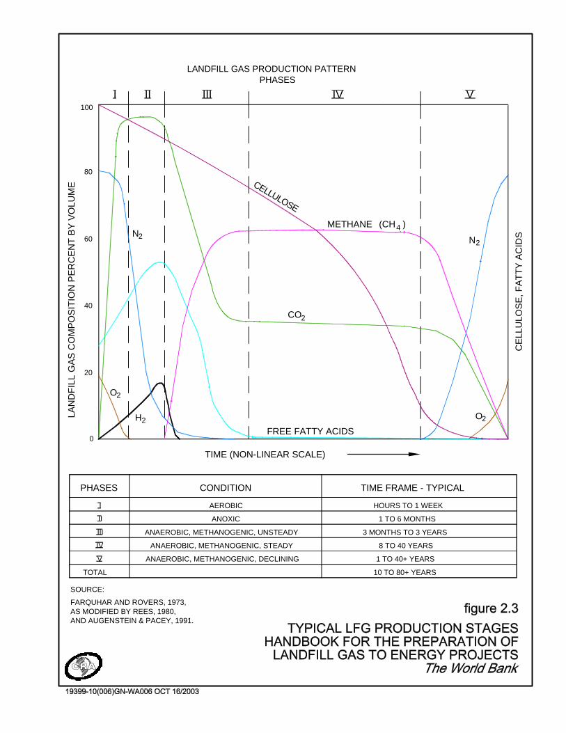
The quality of the LFG depends on the microbial system, the substrate (waste) beingdecomposed, and site-specific variables such as oxygen access to the waste and moisturecontent (Ham, 1989). LFG is typically described as consisting of approximately50 percent methane and 50 percent carbon dioxide with less than 1 percent other trace gasconstituents, including hydrogen sulfide (H2S) and mercaptans.
There are four LFG production phases that occur throughout the life of a landfill.Farquhar and Rovers predicted generation of gas in a landfill for typical municipal solidwaste (MSW) in the 1970s. A graph of the LFG generation phases is shown asFigure 2.3. The duration of each of these phases is dependent on a number of factorsincluding the type of waste, moisture content, nutrient content, bacterial content, and pHlevel. Some general guidelines regarding the length of the decomposition cycle for thevarious categories of waste are provided in the following table. Note that this is a generalguideline only. The extreme heterogeneity of the waste in a typical landfill site, togetherwith the environment in a specific landfill has a significant bearing on this factor suchthat it can not be simply provided on a generic basis.
100
80
60
40
20
0
LAN
DF
ILL
GA
S C
OM
PO
SIT
ION
PE
RC
EN
T B
Y V
OLU
ME
TIME (NON-LINEAR SCALE)
N2
O2
2H
CELLULOSE
LANDFILL GAS PRODUCTION PATTERNPHASES
IIIIII IV
PHASES CONDITION
V
TIME FRAME - TYPICAL
TOTAL
ANOXIC
ANAEROBIC, METHANOGENIC, UNSTEADY
AEROBIC
ANAEROBIC, METHANOGENIC, STEADY
ANAEROBIC, METHANOGENIC, DECLINING
HOURS TO 1 WEEK
1 TO 6 MONTHS
3 MONTHS TO 3 YEARS
8 TO 40 YEARS
1 TO 40+ YEARS
10 TO 80+ YEARS
SOURCE:
FARQUHAR AND ROVERS, 1973,AS MODIFIED BY REES, 1980,AND AUGENSTEIN & PACEY, 1991.
METHANE
CO2
FREE FATTY ACIDS
N2
CE
LLU
LOS
E, F
AT
TY
AC
IDS
(CH4 )
O2
I
II
III
IV
V

18 Landfill Gas – Understanding the Resource
Half-Lives of Biodegradation Byproducts
Waste Category Minimum Half-Life Maximum Half-Life
Rapidly Decomposable (food& garden wastes etc.)
½ year 1 ½ year
Moderately Decomposable(paper etc.)
5 years 25 years
Poorly Decomposable (someportions of construction &demolition wastes etc.)
10 years 50 years
The first phase, aerobic decomposition, occurs immediately after the waste has beenplaced, while oxygen is present within the refuse. Aerobic decomposition producescarbon dioxide, water, and heat. The next stage is the anoxic, non-methanogenic phasewhere acidic compounds and hydrogen gas are formed and while there is continuedcarbon dioxide production. The third phase is the unsteady methanogenic phase. Duringthis phase, the carbon dioxide production begins to decline because waste decompositionmoves from aerobic decomposition to anaerobic decomposition. Anaerobicdecomposition produces heat and water, but unlike aerobic decomposition, it alsoproduces methane. During the fourth phase methane is generated at between 40 and70 percent of total volume (McBean, 1995). Typically, the waste in most landfill siteswill reach the stable methanogenic phase within less than 2 years after the waste has beenplaced. Depending on the depth of the waste lifts, and the moisture content of the waste,the methanogenic phase might be reached as early as six months after placement. LFGmay be produced at a site for a number of decades with emissions continuing at declininglevels for up to 100 years from the date of placement. This can be seen in Figure 2.2,which will be used for discussion purposes in the Handbook as a typical representation ofa moderately sized site in LAC.
2.4 Potential LFG Impacts
The emission rate at which the release of LFG becomes an issue with regulatoryauthorities and neighboring property owners is related to a number of physical parametersincluding: the location of the landfill; the surrounding topography; adjacent land uses;ambient meteorological conditions; and the site characteristics that impact LFGgeneration and collection (Mosher, 1996).
It is generally the trace constituents, hydrogen sulfide (H2S) and mercaptans, which arethe primary compounds that are associated with nuisance odor emissions from landfills.These compounds typically constitute less than 1 percent of LFG, but odors arecompound-specific and can be detected for specific chemical concentrations of as little as

19 Landfill Gas – Understanding the Resource
0.001 to 0.005 parts per million (ppm). The level at which these chemicals might be ofharm to human-health varies, but is typically orders of magnitude greater than thosereferenced. This means that the detection of odor is not necessarily an indication of ahealth concern but it can be a real nuisance and an adverse condition with regard to thequality of life in the area of the landfill.
Odor resulting from the release of LFG operates on a threshold principle. Thus, if theamount of LFG exceeds the threshold level for the particular conditions at the landfill,there will be odor related to the production of LFG. The following analogy can be usedto better understand the concept of an odor threshold. Let the volume of a cup representthe total amount of LFG that can be released before reaching the odor threshold. The sizeof this "cup" for each landfill is determined by a number of factors, including the landfilllocation, surrounding topography and ambient meteorological conditions. Let waterpoured into the cup represent the release of untreated LFG. The cup can be "full to thebrim" and still not spill any liquid. However, if the capacity of the cup is exceeded, byeven one drop, it will overflow and liquid will spill out. Therefore, the amount of waterin the cup can vary up to the capacity of the cup, so long as that threshold volume is notexceeded. This concept is analogous for LFG odor emissions. To ensure that nuisanceodor is not a concern, the amount of LFG released would need to be lower than the odorthreshold of the landfill site, for the given meteorological and other conditions.Therefore, in the situation where LFG odor is a major concern, it is less important howmuch LFG is collected in comparison with how much LFG is released from the landfill(Mosher, 1996), and whether or not that amount of LFG released exceeds the site'sthreshold. This issue is somewhat complicated by the fact that the threshold limit is not afixed number. It varies depending upon time sensitive meteorological conditions andseparating distance between the landfill and odor receptors (e.g., residents).
The most important component of LFG from most perspectives is methane, whichconstitutes approximately 50 percent of the LFG volume produced. Methane is apotential hazard since it is combustible and explosive at concentrations between 5 and15 percent in air. LFG can migrate below ground surface in the unsaturated soil zones,especially during winter and spring months when the ground is frozen or saturated withmoisture at surface. LFG can then accumulate in enclosed structures causing apotential hazard. Methane has no odor and, is therefore, impossible to detect withoutproper instrumentation.
Methane released from landfills has also been identified as a significant contributor togreenhouse gas (GHG) emissions, which contribute to global warming. Over a 100-yeartime horizon, in comparison with carbon dioxide, methane is considered to be 21 timesmore efficient at trapping heat within the atmosphere (IPCC, 1995). This value iscurrently under review and could potentially be revised upwards in the future, furtherincreasing the incentive for LFG management projects. Methane generated from solidwaste and wastewater, through anaerobic decomposition, represents about 20 percent ofhuman-induced methane emissions (IPCC, 1999). LFG emissions to the atmosphere canbe reduced through traditional waste reduction measures, such as recycling and

20 Landfill Gas – Understanding the Resource
composting. Emissions can also be reduced by capturing and flaring the LFG at a hightemperature, converting the methane fraction of the gas into less harmful carbon dioxideand water vapor.
2.5 Potential LFG Benefits
Although there are several negative issues that can arise from the presence of LFG, thereare also a number of benefits associated with the proper management of LFG, and itspotential for use as an energy source. LFG management projects that collect and flare theLFG have the potential to generate revenue through the sale and transfer of emissionreduction credits, which provide an incentive and means to improve the design andoperation of the landfill and to develop a better overall waste management system.
LFG is approximately 50 percent methane, and can be considered a low/medium gradefuel. This resource can be harnessed in a number of applications including direct fuel usefor heating, electrical generation, and commercial chemical byproducts. In addition tomitigating LFG migration and odor concerns, LFG utilization can also generate revenuesfrom the sale of "green power" and other LFG products that can defray the costs oflandfill operation and maintenance and provide incentive to improve landfill design andoperation.
Emission reductions represent the global and national objectives for improving global airquality. Emission Credits (GHG Credits) and Green Power energy premiums are two ofthe key mechanisms that are being proposed to help to achieve the goal of "EmissionReductions". The sale of these credits can be used to improve the economics of apotential project. There is differing terminology used to refer to the emission reductionssuch as ERs, CERs and GHG credits. These terms refer essentially to the same item,which is best defined as the quantity of emission reductions converted and presented inthe common unit of equivalent tonnes of carbon dioxide emission reductions. For thebalance of the Handbook, the term CER will be used and the unit of definition willalways be equivalent tonnes of carbon dioxide. The CER designation assumes that theemission reductions have been certified to meet a specific set of standards andrequirements. There may be other certifying agencies or bodies that may use differentacronyms but the principles and underlying basis for recognition and quantification willremain the same.
Before any LFG management project is undertaken, the LFG emissions and resultingCERs must be carefully assessed and the potential markets explored. This is discussed inmuch more detail in later sections.
2.6 LFG Collection System
There are extensive reference materials and information with respect to the successfulmeans and methods to collect and flare LFG that are generally beyond the scope of thisHandbook. However, a basic understanding of the nature and operation of the LFGcollection systems is necessary to understand the fundamental elements of a LFG

21 Landfill Gas – Understanding the Resource
management project and risk factors inherent in the management of the LFG resource.To appreciate the interconnection and interdependence issues, a brief outline of theelements of a collection system is being provided. A typical LFG collection system iscomprised of the following components:
• LFG collection field (wells and trenches);
• Collection piping (laterals, subheaders, headers, etc.);
• Condensate drop-out and disposal system;
• Blower system and related appurtenances; and
• LFG flare.
LFG management can be achieved through the use of these components and there ispotential, through the development of the international carbon market, for this type ofsystem to generate revenue through the creation of GHG emission reduction credits.Revenue provided by such a system creates an incentive for better landfill design andmanagement, and a contribution towards improvement of the overall waste managementsystem.
Appendix A provides a number of figures illustrating various components of a typicalLFG collection and flaring system for review and reference.
LFG Collection Field
A network of vertical LFG extraction wells and/or horizontal LFG collection trenches areinstalled into the waste to collect the LFG. The basic operating principle is quite simple,apply a vacuum to extract the gases from the waste mass as closely matched to the rate atwhich the gas is being generated within the influence area of the well or trench as ispractical. The idealized target objective is to establish a neutral pressure/vacuumgradient continuously over the entire surface of the landfill. It is important to recognizethat the ideal condition cannot be achieved at reasonable cost and therefore, it isimportant to balance the cost-benefit of installing additional wells in a tighter grid ofwells together with a complementary cap system versus the value inherent in the fuelrecovery.
The cost increase to extract LFG up to approximately 75 percent of the actual LFG beinggenerated is considered relatively linear in nature. However, to achieve very highrecovery efficiencies, it may be necessary to employ a very tight grid of extractionwells/trenches and/or a synthetic cover system, which would result in major capital costincreases relative to the gain in LFG recovery. Figure 2.4 illustrates the relationshipbetween the efficiency of the LFG collection system and the relative cost.
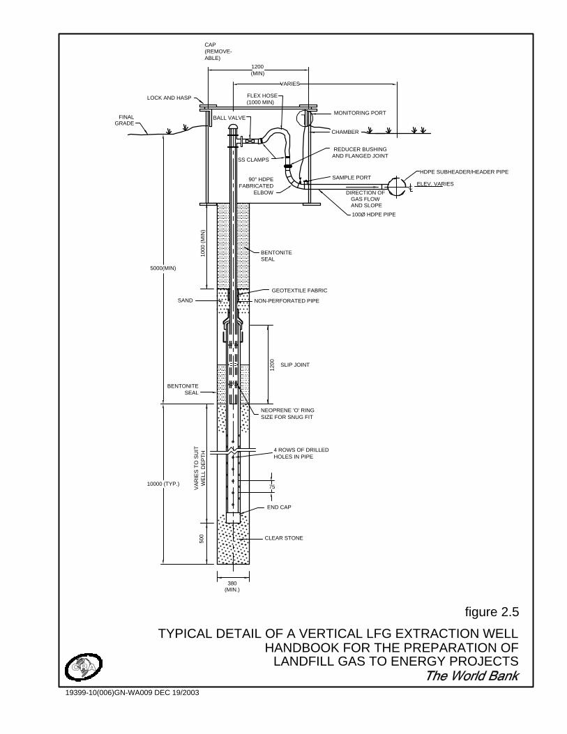
Vertical wells are typically installed in a landfill once filling operations have beencompleted. Figure 2.5 shows the construction of a typical vertical LFG extraction well.Figure 2.6 shows the construction of a typical horizontal LFG extraction trench. Usingvertical LFG extraction wells has the following advantages:

0 40 70 90 100
% RECOVERY
0
$ 0.50 USD/cfm
$ 3.00 USD/cfm
CO
ST
/cfm
$ 1.00 USD/cfm
figure 2.4
COST VERSUS RECOVERY EFFICIENCYHANDBOOK FOR THE PREPARATION OF
LANDFILL GAS TO ENERGY PROJECT
19399-10(006)GN-WA023 DEC 19/2003
ABLE)(REMOVE-CAP
FINAL
LOCK AND HASP
HDPE SUBHEADER/HEADER PIPE
ELEV. VARIESC
100Ø HDPE PIPE
HOLES IN PIPE
CLEAR STONE
(MIN.)380
500
WE
LL D
EP
TH
VA
RIE
S T
O S
UIT
END CAP
SIZE FOR SNUG FITNEOPRENE 'O' RING
4 ROWS OF DRILLED
SAND
1200 SLIP JOINT
NON-PERFORATED PIPE
1000
(M
IN)
SEALBENTONITE
GEOTEXTILE FABRIC
GRADE
DIRECTION OFGAS FLOW
CHAMBER
90° HDPE FABRICATED
ELBOW
REDUCER BUSHINGAND FLANGED JOINT
BENTONITE SEAL
SAMPLE PORT
AND SLOPE
SS CLAMPS
MONITORING PORT
75
5000(MIN)
BALL VALVE
VARIES
1200(MIN)
FLEX HOSE(1000 MIN)
10000 (TYP.)
figure 2.5
TYPICAL DETAIL OF A VERTICAL LFG EXTRACTION WELLHANDBOOK FOR THE PREPARATION OF
LANDFILL GAS TO ENERGY PROJECTS
19399-10(006)GN-WA009 DEC 19/2003
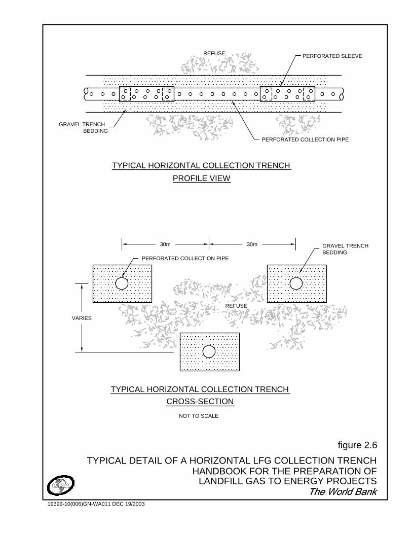
CROSS-SECTION
TYPICAL HORIZONTAL COLLECTION TRENCH
NOT TO SCALE
PROFILE VIEW
TYPICAL HORIZONTAL COLLECTION TRENCH
GRAVEL TRENCH BEDDING
PERFORATED COLLECTION PIPE
PERFORATED SLEEVE
GRAVEL TRENCH BEDDING
PERFORATED COLLECTION PIPE
REFUSE
REFUSE
30m 30m
VARIES
figure 2.6
TYPICAL DETAIL OF A HORIZONTAL LFG COLLECTION TRENCHHANDBOOK FOR THE PREPARATION OF
LANDFILL GAS TO ENERGY PROJECTS
19399-10(006)GN-WA011 DEC 19/2003

25 Landfill Gas – Understanding the Resource
• improved areal control of gas emissions;
• well field may be expanded to reflect the changing landfill site conditions; and,
• condensate collection may be minimized.
To maximize collection efficiency, wells should be sited in consideration of the wastedepth, age and the physical geometry of the site. If there is a concern regardingsubsurface migration of LFG, wells placed close to the outer limits of the waste should begrouped closer together to act as a migration control system.
Some of the general rules for the installation of vertical extraction wells are:
• minimum of 3 to 6 m of landfill depth to be maintained above the extraction wellperforations to minimize air entering the LFG collection system;
• the depth from surface to perforations should be increased near side slopes; and
• the ability to install wells along the steeper (4:1) side slopes is limited withconventional drilling equipment.
These conditions may not be absolutely identical at every landfill site, however theyserve as a good guideline to ensure proper function of the LFG collection system andminimize the intrusion of air into the flare or LFGTE plant.
Horizontal LFG collection trenches are typically used to collect gas while the site is stillactive. Following the placement and compaction of a lift of waste, perforated collectionpipes are installed and then covered with another layer of waste. This allows for LFG tobe collected from waste directly below an area where active filling is taking place. Whilethis technique can control LFG emissions in active areas of the site, horizontal collectiontrenches are not generally suitable for localized gas control.
In general, the operating principles for vertical wells and horizontal trenches are thesame. Both types of collectors should be equipped with telescoping sections ofnon-perforated pipe to allow for refuse settlement, which occurs over time. It has beenfound that 10 to 15 inches of water column vacuum at the wellhead or trench represents areasonable compromise between maximizing zones of influence and minimizing airintrusion into the refuse, while using economical LFG extraction equipment. The radiusof the zone of influence with this vacuum ranges from less than 20 m to more 100 m,depending on the waste's heterogeneity and other related characteristics.
The LFG collection system should be used in concert with good leachate managementpractices. Leachate mounding within the refuse can dramatically impact the rate of LFGrecovery because liquid in the extraction wells and collection trenches effectivelyrestricts their ability to collect and convey LFG. In extremely damp sites, the effectiveLFG fuel recovery may drop to less that 50 percent of the estimated quantity of LFG thatmay be available.
The costs to install vertical wells can vary dramatically as a function of: local costs formaterials such as aggregate, pipe and grout; contractor availability; available equipment
26 Landfill Gas – Understanding the Resource
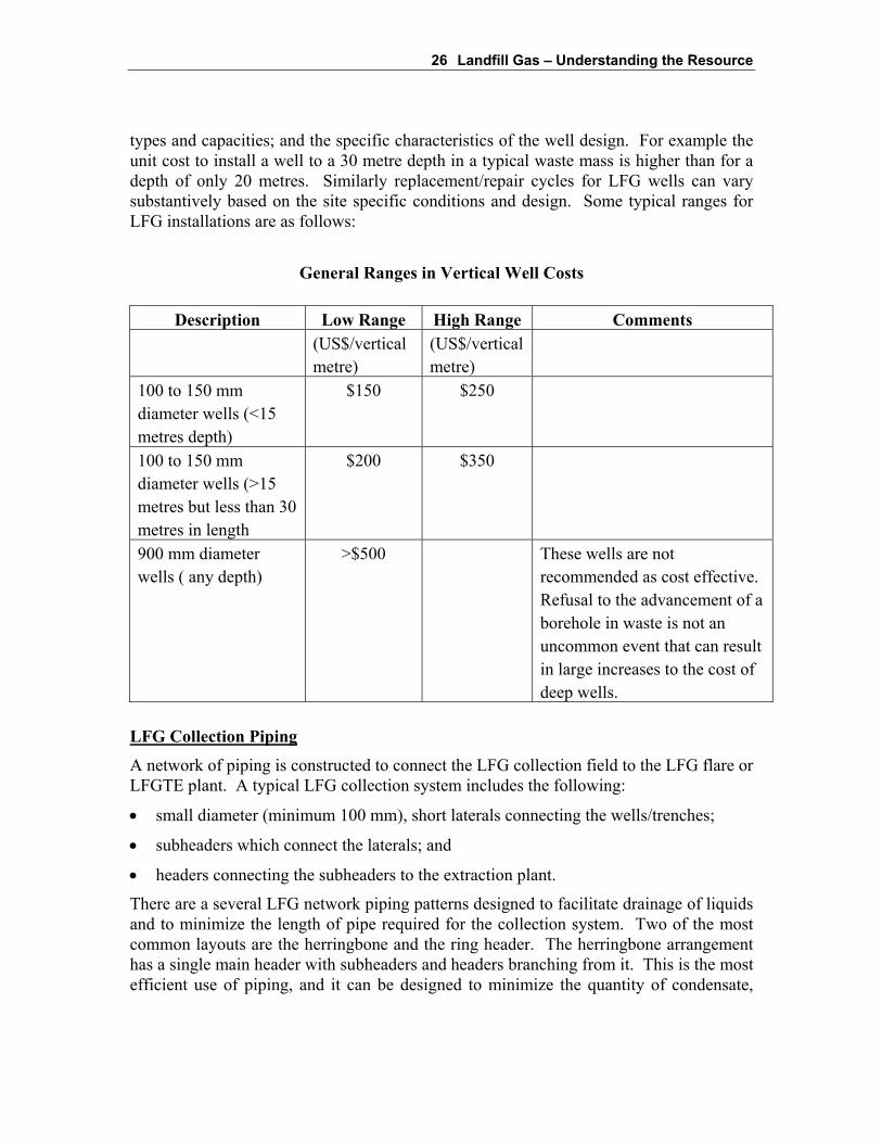
types and capacities; and the specific characteristics of the well design. For example theunit cost to install a well to a 30 metre depth in a typical waste mass is higher than for adepth of only 20 metres. Similarly replacement/repair cycles for LFG wells can varysubstantively based on the site specific conditions and design. Some typical ranges forLFG installations are as follows:
General Ranges in Vertical Well Costs
Description Low Range High Range Comments(US$/verticalmetre)
(US$/verticalmetre)
100 to 150 mmdiameter wells (<15metres depth)
$150 $250
100 to 150 mmdiameter wells (>15metres but less than 30metres in length
$200 $350
900 mm diameterwells ( any depth)
>$500 These wells are notrecommended as cost effective.Refusal to the advancement of aborehole in waste is not anuncommon event that can resultin large increases to the cost ofdeep wells.
LFG Collection Piping
A network of piping is constructed to connect the LFG collection field to the LFG flare orLFGTE plant. A typical LFG collection system includes the following:
• small diameter (minimum 100 mm), short laterals connecting the wells/trenches;
• subheaders which connect the laterals; and
• headers connecting the subheaders to the extraction plant.
There are a several LFG network piping patterns designed to facilitate drainage of liquidsand to minimize the length of pipe required for the collection system. Two of the mostcommon layouts are the herringbone and the ring header. The herringbone arrangementhas a single main header with subheaders and headers branching from it. This is the mostefficient use of piping, and it can be designed to minimize the quantity of condensate,

27 Landfill Gas – Understanding the Resource
which accumulates in the LFG collection system, by sloping the majority of pipingtowards the LFG wells.
An on-site ring header may be used when there is no land available for construction of aheader system outside the limit of waste. Off-site ring headers reduce some of theproblems associated with placement of piping into the refuse. Ring headers should beequipped with valves to allow isolation of portions of the site, and monitoring ports tomonitor gas quality and quantity. Dual header systems have been utilized at some largeand deep landfill sites that have a long active site life to segregate the methane-rich gasfrom the deeper portions of the site from the gas collected from near the surface that maybe diluted via air intrusion. There are numerous design criteria/constraints related to thepiping installations to specify such as minimum and maximum slopes; condensatemoisture removal; differential and total settlement stresses; and dead and live loadstresses.
The relative costs of the piping systems to collect and transport the LFG to the facilitycan vary substantively based on site specific conditions and the applicable design basis.For example, above grade piping systems are the least expensive to construct and areoften used for temporary systems or for short term repairs but also have successfully beenused for full-scale long-term systems. There are advantages and disadvantages to bothabove and below ground approaches to the installation of the connecting piping systems.The costs for small diameter above grade piping can be less than $30/metre but largerdiameter buried piping can cost up to, and more than, $200/metre. The cost is highlyinfluenced by factors such as:
• the nature of the design (e.g., above or below grade);
• the need to remove and relocate any waste;
• the need to add fill or grade areas of the cap and perimeter areas;
• the extent and number of condensate removal traps;
• the cost of petroleum and associated products; and
• the availability and costs for suitable construction contractors.
The specific characteristics of a landfill site will have many direct implications for thedesign options and related costs of the piping systems. As such, it is highlyrecommended that these costs be reviewed carefully on a project specific basis. It is alsoimportant to note that high density polyethylene (HDPE) piping is highly recommendedfor most of the LFG piping and its price is largely controlled by the relative cost ofpetroleum and the proximity to suitable pipe manufacturing facilities.
Blower System and Related Appurtenances
The blower system includes all components that are used to generate and apply thevacuum to collect the LFG and supply it for its subsequent end use. A blower systemshould be centrally located with sufficient space for expansion, close to the end user
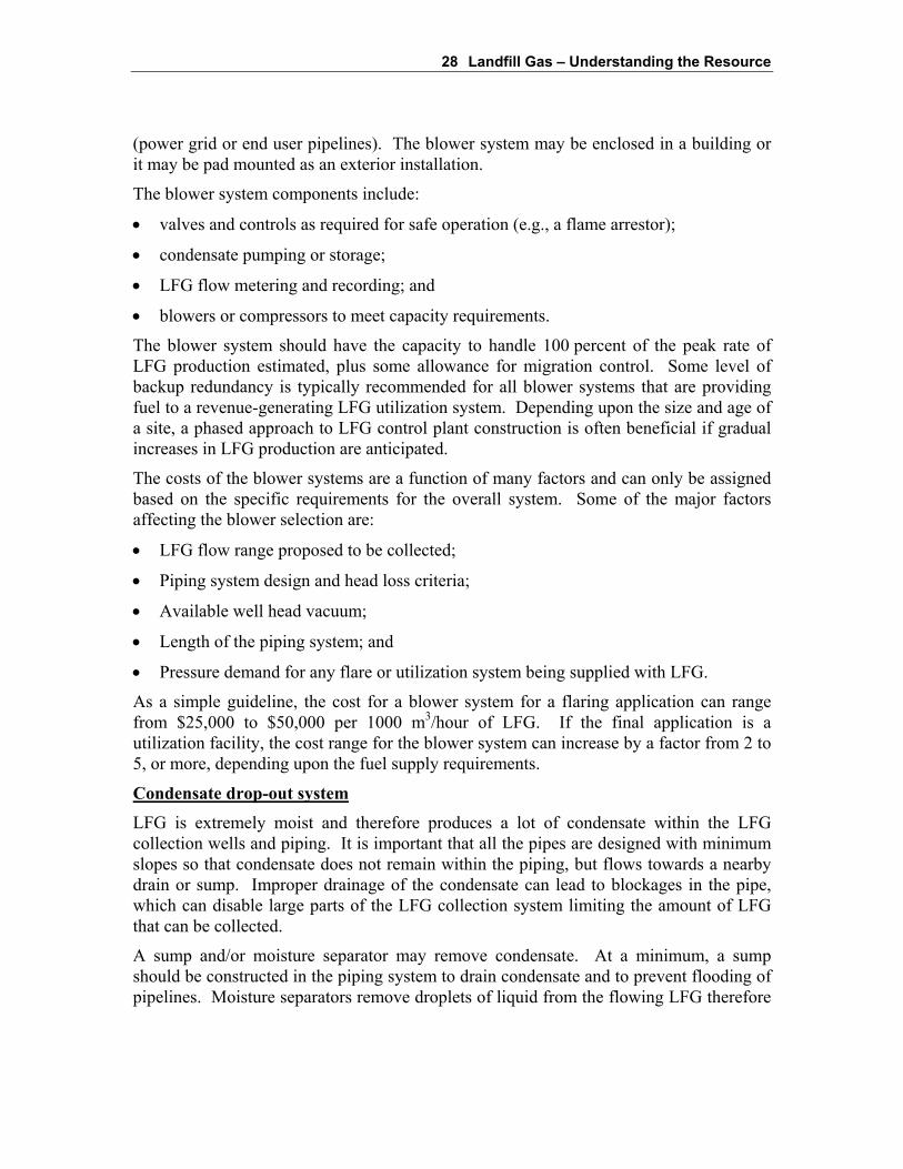
28 Landfill Gas – Understanding the Resource
(power grid or end user pipelines). The blower system may be enclosed in a building orit may be pad mounted as an exterior installation.
The blower system components include:
• valves and controls as required for safe operation (e.g., a flame arrestor);
• condensate pumping or storage;
• LFG flow metering and recording; and
• blowers or compressors to meet capacity requirements.
The blower system should have the capacity to handle 100 percent of the peak rate ofLFG production estimated, plus some allowance for migration control. Some level ofbackup redundancy is typically recommended for all blower systems that are providingfuel to a revenue-generating LFG utilization system. Depending upon the size and age ofa site, a phased approach to LFG control plant construction is often beneficial if gradualincreases in LFG production are anticipated.
The costs of the blower systems are a function of many factors and can only be assignedbased on the specific requirements for the overall system. Some of the major factorsaffecting the blower selection are:
• LFG flow range proposed to be collected;
• Piping system design and head loss criteria;
• Available well head vacuum;
• Length of the piping system; and
• Pressure demand for any flare or utilization system being supplied with LFG.
As a simple guideline, the cost for a blower system for a flaring application can rangefrom $25,000 to $50,000 per 1000 m3/hour of LFG. If the final application is autilization facility, the cost range for the blower system can increase by a factor from 2 to5, or more, depending upon the fuel supply requirements.
Condensate drop-out system
LFG is extremely moist and therefore produces a lot of condensate within the LFGcollection wells and piping. It is important that all the pipes are designed with minimumslopes so that condensate does not remain within the piping, but flows towards a nearbydrain or sump. Improper drainage of the condensate can lead to blockages in the pipe,which can disable large parts of the LFG collection system limiting the amount of LFGthat can be collected.
A sump and/or moisture separator may remove condensate. At a minimum, a sumpshould be constructed in the piping system to drain condensate and to prevent flooding ofpipelines. Moisture separators remove droplets of liquid from the flowing LFG therefore

29 Landfill Gas – Understanding the Resource
reducing the detrimental effects that the corrosive condensate may have on the LFGhandling equipment.
BOX 2: IMPORTANCE OF CONDENSATE MANAGEMENT TO LFGCOLLECTION SYSTEM PERFORMANCE
One of the most common operational problems for LFG collection systems is liquidblockage in the piping or wells, which has the potential to cripple the operation of thesystem. Blockage of the laterals or subheaders usually results from a build up ofcondensate. Condensate removal systems should be installed to collect and remove LFGcondensate from the piping systems. The blockage problems caused by inadequatelysized piping or piping designed with an inadequate slope, can effectively terminate LFGcollection from the affected section of the landfill. Another reason for condensatebuild-up is the uneven or differential settlement of the waste, which can cause a dip orlow point in the piping systems that can then fill with condensate. It is for this reasonthat LFG collection systems should be designed with a great deal of excess capacity andspecific consideration in the design for identifying and addressing settlement issues.
A demonstration of the potentially catastrophic consequences that ineffective condensatemanagement can have is the Kemerburgaz LFGTE project in Turkey. During the startupand commissioning phase, it was found initially that two thirds of the LFG extractionwells had no suction pressure, which meant that there was not enough LFG to supply theengines that were being commissioned. Thankfully, this condition was remedied after aweek when it was discovered that a section of pipe had been installed such thatcondensate was collecting and blocking the pipe, preventing LFG extraction from asignificant portion of the site.
The LFGTE project in Krakow, Poland has experienced difficulties with the flooding oftheir horizontal LFG collection trenches because of leachate mounding within the wastemass. In the future, they are planning to use only vertical LFG extraction wells to combatthis problem. The LFGTE project in Olsztyn, Poland has experienced such high leachatelevels that all the perforations in the vertical LFG extraction wells are blocked and thewells have been rendered dysfunctional.
At the Waterloo Landfill in Canada, the quantity of LFG recovered has not increased tocorrespond with the quantity of wells that are presently in-place. Conditions at this siteserve to reinforce the importance of understanding the landfill and its operation as well asthe physical conditions within the landfill. The Site was found to be very wet, hamperingthe ability to obtain the gas that is being generated in some portions of the Site. Systemsto address the presence of condensate and trace gas impurities in the LFG can requiresscrubbers and other treatment systems similar to the equipment shown in the attachedpicture of a portion of the gas treatment room at the Waterloo Landfill Site.

30 Landfill Gas – Understanding the Resource
The importance and benefits associated with effective condensate management to boththe short and long-term performance of the LFG management systems can not beoverstated. This is a critical item to the success of all LFG management projects that isnot always given the consideration that is warranted.
Once separated from LFG, condensate must be disposed of in an environmentally soundmanner. Condensate is generally more concentrated than leachate and may be considereda hazardous liquid waste in some jurisdictions.
LFG flare
The LFG collected from a site must be disposed of in an environmentally sound mannersuch as an enclosed drum flare and/or utilization system. A LFG flare can be used as abackup to the utilization system in case of lengthy downtimes for both scheduled andunscheduled equipment operating and maintenance events. The need for a backup flareand equipment redundancy is optional depending upon the overall systems reliability andthe sensitivity to short term loss of LFG extraction and control capability. Hightemperature flaring of LFG results in conversion of methane components of the LFG tocarbon dioxide and water. As well, this high temperature combustion ensures that thetrace compounds in LFG are largely destroyed. Most LFG utilization systems provide fordestruction efficiencies equal to or better than those achieved in the enclosed drum flares.

31 Landfill Gas – Understanding the Resource
As with most of the other system components, the cost of flaring systems is a function ofthe overall design of the LFG management system and the performance requirements thatare expected for the flare. There are 2 basic flare designs; the enclosed drum flarediscussed above; and a waste gas flare that simply ignites the methane without anyextensive combustion controls. This second type of flare is in common use in manyjurisdictions but has not been the focus of this Handbook, primarily because its use is notdeemed acceptable if there is any intent to qualify for CERs.
To give a simple cost guideline, a waste gas flare capable of combusting 1000 m3/hour ofLFG would cost in the range between $50,000 and $100,000 depending upon theperipheral controls and safety features required. For relative comparison, an encloseddrum flare with a similar capacity with have a cost range about twice that of the wastegas flare. Some components such as the refractory and control systems can varysubstantively in price depending upon the performance requirements.
2.7 Operation of LFG Collection System
Active LFG collection and utilization are highly effective for mitigation of on-site andoff-site LFG impacts as well as reduction of GHG emissions to the atmosphere. TheLFG capture potential is highly dependent on site design related factors, such as:
• Site configuration (depth of waste, landfill area, depth of water table);
• liner system design;
• cover system design;
• moisture addition/leachate recirculation; and
• operational constraints.
Site configuration has a great impact on the LFG collection potential for a site. Sites thatare filled above the natural grade tend to have larger surface areas, therefore increasingthe chances of LFG emissions. Sites filled below grade have a greater tendency foroff-site LFG migration through the surrounding soils.
A low permeability soil or synthetic liner system combined with a leachate collectionsystem is beneficial in controlling both LFG migration and mounding of leachate withinthe refuse. The primary purpose for a low permeability liner is to mitigate potentialgroundwater impacts by allowing leachate recovery from the bottom of the refuse, but itis also recommended for the control of LFG migration.
The permeability of the final cover system is an important factor in LFG managementand system performance. Low permeability covers minimize LFG venting to theatmosphere, air intrusion into the waste, as well as moisture infiltration. A lowpermeability cover can help to improve the performance and areas of influence forvertical extraction wells. However, if the cover system is very tight and allows very littleinfiltration, it can retard or slow down the rate of decomposition in the upper portion of
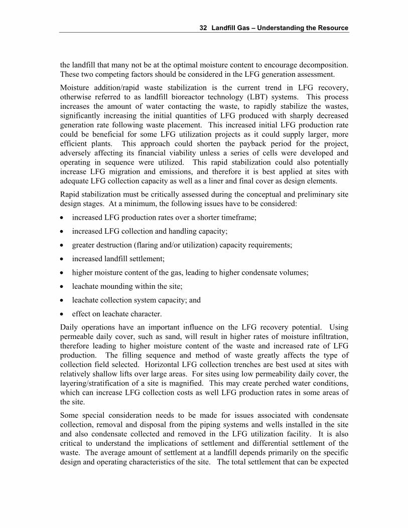
32 Landfill Gas – Understanding the Resource
the landfill that many not be at the optimal moisture content to encourage decomposition.These two competing factors should be considered in the LFG generation assessment.
Moisture addition/rapid waste stabilization is the current trend in LFG recovery,otherwise referred to as landfill bioreactor technology (LBT) systems. This processincreases the amount of water contacting the waste, to rapidly stabilize the wastes,significantly increasing the initial quantities of LFG produced with sharply decreasedgeneration rate following waste placement. This increased initial LFG production ratecould be beneficial for some LFG utilization projects as it could supply larger, moreefficient plants. This approach could shorten the payback period for the project,adversely affecting its financial viability unless a series of cells were developed andoperating in sequence were utilized. This rapid stabilization could also potentiallyincrease LFG migration and emissions, and therefore it is best applied at sites withadequate LFG collection capacity as well as a liner and final cover as design elements.
Rapid stabilization must be critically assessed during the conceptual and preliminary sitedesign stages. At a minimum, the following issues have to be considered:
• increased LFG production rates over a shorter timeframe;
• increased LFG collection and handling capacity;
• greater destruction (flaring and/or utilization) capacity requirements;
• increased landfill settlement;
• higher moisture content of the gas, leading to higher condensate volumes;
• leachate mounding within the site;
• leachate collection system capacity; and
• effect on leachate character.
Daily operations have an important influence on the LFG recovery potential. Usingpermeable daily cover, such as sand, will result in higher rates of moisture infiltration,therefore leading to higher moisture content of the waste and increased rate of LFGproduction. The filling sequence and method of waste greatly affects the type ofcollection field selected. Horizontal LFG collection trenches are best used at sites withrelatively shallow lifts over large areas. For sites using low permeability daily cover, thelayering/stratification of a site is magnified. This may create perched water conditions,which can increase LFG collection costs as well LFG production rates in some areas ofthe site.
Some special consideration needs to be made for issues associated with condensatecollection, removal and disposal from the piping systems and wells installed in the siteand also condensate collected and removed in the LFG utilization facility. It is alsocritical to understand the implications of settlement and differential settlement of thewaste. The average amount of settlement at a landfill depends primarily on the specificdesign and operating characteristics of the site. The total settlement that can be expected

33 Landfill Gas – Understanding the Resource
from a landfill site can range from 20 to 40 percent of the total depth of the wastefollowing initial placement and compaction. In simple terms, a 30 metre deep landfillcould experience total settlement from 6 to 12 metres by the time the process iscompleted. The rate of settlement is at its peak when the site is still actively receivingwaste. Both the load related settlement and decomposition related settlement aretypically at their peak during the active site life. More important than total settlement isdifferential settlement. Settlement in localized areas can be much greater and much morerapid than the average depending on the material landfilled, the amount of compaction itreceives, and other factors such as air intrusion or the infiltration of surface water.Features such as vertical gas wells can be localized problem areas if not taken intoaccount during both the design phase and as a key consideration of the operations andmaintenance phase of any project.
2.8 Best Management Practices for Operations of LFGProjects to Maximize Energy Recovery Potential
Optimizing LFG collection is directly related to maximizing LFG utilization potential,realizing economic benefits from the sale of LFG energy and reducing GHG emissions.It must always be understood that the landfill operation itself is the primary purpose ofthe site activities and all other systems or supporting activities, whether beneficial or not,must remain subservient to this activity. One problem area that has been notedthroughout the history of the LFG management projects is that improper operation of aLFG collection system to support a utilization system can pose risks of landfill fires andfuel quantity reduction that are both dangerous and counterproductive for both of thesystems. Understanding the links and interactions between these two systems isimportant to developing and sustaining a viable project through the entire term of a20-year or longer contract term, which can be critical for a LFGTE plant.
LFG COLLECTION FIELD
A well designed, constructed and operated LFG recovery system can collect 75 percent ormore of the LFG produced at a site. It is important for a collection system to be designedand operated to match the site's changing LFG generation potential without over or underdrawing on the collection field. In addition to the changing LFG generation rate over thelife of the landfill, the effective LFG generation rate also varies somewhat over the shortterm as a function of factors such as; meteorological conditions; differential settlement;equipment efficiencies; and cover system conditions. The collection field must beadjusted to match the changing effective generation rate. The LFG collection field mustbe periodically monitored and adjusted to optimize the effectiveness of the collectionsystem. The adjustment of valve settings to reduce or increase LFG flows from low orhigh production areas of the landfill is required to maximize LFG collection withoutoverdrawing from those areas of the site that may be susceptible to air intrusion. Oneprinciple that is often misunderstood or ignored, even by those working in the LFGindustry, is that the operating basis for an individual well or trench must be based solely

34 Landfill Gas – Understanding the Resource
on LFG quality at that individual well or trench. Operating a well or trench on the basisof target recovery rates or expected performance yields is counter-productive.
Air intrusion into the landfill must be minimized since it has a negative impact on thenatural decomposition of waste. Within a few months following placement, thewaste-in-place has typically reached a stable phase of anaerobic (oxygen-free)decomposition. At this point, introducing oxygen will return this environment intoaerobic conditions, with the result of: reducing methane generation and an associateddecline in potential fuel recovery; increased localized rates of differential settlement;higher subsurface temperatures in the waste; and potentially increased odor problems.This condition may also lead to landfill fires and increases the potential for spreading anyfires that are started.
Field monitoring at each of the collection points (wellheads/trenches) should include:
• vacuum;
• differential pressure;
• temperature;
• LFG composition (methane and O2 content); and
• valve position
Monitoring of each collection point should start with vacuum/pressure measurement toavoid interference with the action of extraction for the LFG sample. The essentialmonitoring data to collect is the vacuum, LFG composition and valve position. Thefollowing indicates readings under ideal operating conditions to maximize energyrecovery at each collection point:
• Vacuum maximum 20 inches WC;
• methane 45 to 55 percent by volume;
• O2 less than 2 percent by volume.
Table 2.1 presents a simple diagnosis tool to highlight some common problems in theoperation of the LFG collection and utilization facilities and their probable solutions.

35 Landfill Gas – Understanding the Resource
Table 2.1 – Common LFG Collection System and Fuel Recovery Issues
Diagnosis Potential results Recommended solution
O2 > 2 percent v/v • Diluting LFG fuel thereforereducing energy recovery
• Increased rates of differentialsettlement
• High subsurface temperatures• Odor problems• Landfill fires
• Adjust valves and rebalancebased on gas quality
• Check well head for indicationsof differential settlement stresses
CH4 < 45 percentv/v
• Same as above • Adjust valves and rebalancebased on gas quality
• Check well head for indicationsof differential settlement stresses
CH4 > 55 percentv/v
• Increased energy content per unitLFG recovered
• Odor problems• Vegetation stress• Increased emissions and
migration
• Adjust valves and rebalancebased on gas quality
• If gas quality and quantity areindicative of additional gas inarea, add wells to system
Vacuum > 20 "WC with highrelative flow rates
• Potential air intrusion• Increased rates of differential
settlement• Landfill fires• Odor problems
• Adjust valves and rebalancebased on gas quality
• If gas quality and quantity areindicative of additional gas inarea, add wells to system
Vacuum < 10 "WC with lowrelative flow rates
• Blockage/breakage of extractionpiping
• Condensate issues• Odor problems• Vegetation stressIncreased emissions migration
• Check well head for indicationsof differential settlement stresses
• Identify and address for blockedpiping
As part of the regular monitoring program the well head valves should be adjusted tomaximize effectiveness. This adjustment must be made based upon review of historicperformance data and within the context of the overall field operation. For instance anygreat variation of vacuum readings from historical monitoring may indicate defects with
36 Landfill Gas – Understanding the Resource
the LFG collection piping, such as break or flooding of pipe runs due to excessivesettlement. For this reason all the data collected must be looked at as a whole.
At a closed landfill site the LFG generation potential is decreasing with time, thereforesome areas of the site may require reduced LFG collection to match this decreasedgeneration. At active landfills LFG generation potential increases until a few years pastclosure. Therefore, LFG collection system design at active sites must allow forprogressive expansion to accommodate the increasing LFG generation.
LFG COLLECTION PLANT
Proper operation and regular maintenance of the LFG collection plant (includingcondensate drop-out(s), blower(s), flare and associated equipment) enhances collectionsystem efficiency and maximizes equipment life.
Regular inspection should be undertaken at the LFG collection plant to record the gasflow, flare temperature, combustible and oxygen concentrations of LFG, bearingtemperatures, motor run times and any other critical parameters. Only personnel familiarwith the operation of the LFG collection system should carry out correction ofirregularities or adjustment to the system operation.
Minor maintenance procedures, such as greasing bearings, changing belts, and calibratingdetectors may be carried out on a monthly cycle. Major system shutdown and equipmentoverhaul should be undertaken annually as per equipment manufacturer'srecommendations.
SYSTEM INTERCONNECTION AND INTERFERENCE ISSUES
Active LFG collection must tie in with other active systems on a site, such as activelandfilling operations, leachate collection, base liner and final cover systems. The overallsite design must take into considerations all systems in a progressive manner to ensureinterconnection of systems and potential progressive site expansion. Some of theinterconnection/interference issues with active LFG collection include:
• Connecting the LFG collection system to the leachate collection system. Thequantity and quality of LFG that may be collected from the leachate system can besignificant. A valve must be installed at the connection point to allow adjustment offlow and pressure applied onto the leachate collection system. The risk of thisconnection is that if excessive vacuum is applied oxygen may be pulled into both theLFG and leachate collection systems. Oxygen intrusion into both of these systemscan be both a safety and operational hazard.
• Ongoing landfilling operations may result in air intrusion into the LFG collectionsystem as well as the landfill itself. At active landfills, care must be taken toprotect/cover the LFG collection pipes with adequate waste/interim cover prior toactivation to minimize air intrusion. Excessive air intrusion will dilute the LFGcollected, reducing its energy content, may cause landfill fires. At open sites anotherrisk is heavy equipment damaging exposed or shallow buried piping.

37 Landfill Gas – Understanding the Resource
• Progressive expansion of LFG collection field is beneficial in increasing LFGcollection capacity but may interfere with existing liner and final cover systems.Following LFG collection field expansion (installation of wells/trenches andassociated laterals) any interruption to the final cover must be replaced to its originalcondition.
Generally, it is always important to remember that a LFG management system is asupplementary operation to the core business of landfilling on the candidate site. Thisfactor must always be considered when looking at installing and operating LFGcollection systems in areas of a site that are still receiving waste and cover materials.

19399 (6) 38 CONESTOGA-ROVERS & ASSOCIATES
3Landfill Gas Utilization Technologies
All LFG utilization facilities require a LFG collection system, which is optimized tomaximize the recovery of the LFG without causing air intrusion. The collection andflaring of LFG is by itself an effective means of LFG management by reducing odor andmigration problems. In addition, flaring LFG in an enclosed drum flare effectivelyconverts the methane in LFG to carbon dioxide, effectively reducing its GHG potential.The implications of this fact, in concert with the development of an international carbonmarket are discussed further in Section 6. Flaring the LFG does not, however, recoverany of the energy from the LFG. This section discusses a number of technologiesavailable to recover some of the energy from the LFG and potentially provide asupplementary source of income to the landfill through the sale of LFG related products.
An effective collection system, associated with a LFG utilization facility, would alsoprotect against odor and other emissions, but as a byproduct of the fuel recovery ratherthan as the primary objective. In an effectively designed and operated LFG collectionsystem, these two sets of objectives can be made fully compatible.
However, LFG is a wet gas with variable concentrations for a number of trace gases,which must be considered in the design of a LFG utilization system. The high moisturecontent of LFG guarantees the presence of moisture in the collection system, which maycause problems related to condensate removal/interference with the ability to collect theLFG through the piping system. In addition, some of the trace gases present incombination with moisture may cause corrosion of the equipment. Other operationalrestrictions such as health hazards such as the danger of explosion from the presence ofLFG in confined spaces prevent the use of LFG for household domestic use. The releaseof contaminants to the atmosphere through air emissions also requires considerationwhen selecting what type of utilization facility to develop. Depending upon theapplication, the raw LFG may require some level of gas processing prior to being utilizedin order to reduce these concerns.
LFG can be classified into three categories, based on the level of pretreatment/processingprior to utilization. These are:
39 Landfill Gas Utilization Technologies
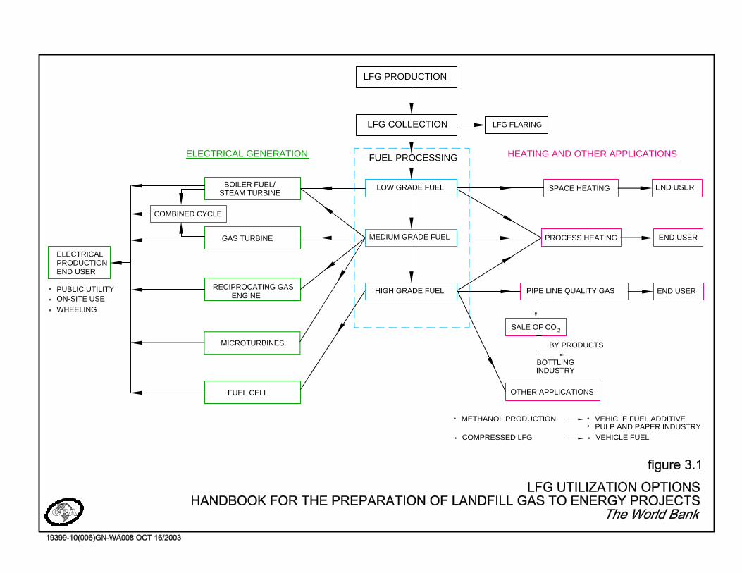
Low-grade LFG fuel - Utilization of LFG as a low-grade fuel typically requiresminimal processing, involving condensate removalchamber(s) as part of the LFG collection system andmoisture knockout pots to reduce the amount of moisture inthe gas stream.
Medium-grade fuel - Additional gas treatment devices are used to extract moremoisture (with contaminants) and finer particulate matter.The process typically involves compression andrefrigeration of LFG and/or chemical treatment orscrubbing to remove additional moisture and trace gascompounds such as mercaptans, sulfur compounds,siloxanes, and volatile organic compounds.
High-grade fuel - Utilization of LFG as a high-grade fuel involves extensivegas pretreatment to separate the carbon dioxide and othermajor constituent gases from the methane and to removeimpurities including mercaptans, sulfur compounds,hydrogen sulfide and volatile organic compounds, and gascompression to dehydrate the gas.
Low- and medium-grade fuel produced from LFG has a heating value of approximately16.8 MJ/m3. This heat value is roughly one-half the heating value of natural gas. LFGthat has been further processed and treated to produce high-grade fuel has a higherheating value (37.3 MJ/m3) than low and medium grade fuel, and can be substituteddirectly for natural gas in pipeline applications (CRA, 1996).
Figure 3.1 provides a visual tool to aid in understanding the following discussion on thevarious applications for the three grades of fuel that can be produced from raw LFG. Italso illustrates the increasing degree of processing that is required to transform the LFGfrom a low-grade fuel into a more refined fuel source.
ELECTRICALPRODUCTIONEND USER
PUBLIC UTILITYON-SITE USE
END USER
END USER
ELECTRICAL GENERATION HEATING AND OTHER APPLICATIONS
END USER
COMPRESSED LFG
METHANOL PRODUCTION VEHICLE FUEL ADDITIVE
VEHICLE FUELPULP AND PAPER INDUSTRY
WHEELING
OTHER APPLICATIONS
SALE OF CO
LFG FLARING
FUEL CELL
STEAM TURBINE
COMBINED CYCLE
ENGINE RECIPROCATING GAS
GAS TURBINE
BOILER FUEL/
FUEL PROCESSING
HIGH GRADE FUEL
MEDIUM GRADE FUEL
LOW GRADE FUEL
LFG COLLECTION
LFG PRODUCTION
2
BY PRODUCTS
INDUSTRYBOTTLING
PIPE LINE QUALITY GAS
PROCESS HEATING
SPACE HEATING
MICROTURBINES

41 Landfill Gas Utilization Technologies
3.1 Low-Grade Fuel Applications
Heating
LFG can be used with minimal treatment to fuel an on-site or off-site furnace, dryingkiln, or boiler. Due to the relatively low heating value, such equipment must be designedto operate on the LFG fuel. The end user must have a constant and adequate demand forthe fuel and be within close proximity to the site. The gas is typically transported to aneighboring facility through a dedicated pipeline. It is necessary to design the supplypipeline to avoid condensate accumulation within the pipeline resulting in possibleblockage. Raw LFG can also be used for small pilot or demonstration projects, such asheating an on-site greenhouse.
Although direct use of the LFG makes intuitive sense, it is necessary for a suitable user toalready exist in close proximity to the site. A "suitable user" means an application thathas a base load user profile, which demonstrates an adequate and continuous year roundfuel demand exceeding the supply available at the site. It also requires the use ofequipment that combusts the fuel with suitable retention time and temperature to ensureadequate destruction efficiency of the numerous trace gas components in the LFG.Criteria for determining the feasibility and suitability of this type of project are furtherdiscussed later in this section.
The costs to develop and implement a low grade heating application are minimal if asuitable application exists in close proximity to the site. There will be some costs for thepiping to deliver the LFG fuel to the desired location. This cost is a function of thequantity of fuel to be delivered and the distances involved. One practical problem withtransmission of low grade fuel is the need for supplementary moisture removal to ensurethat there are no fuel transmission issues with condensate dropout and pipe blockage.The fuel delivery requirements may entail some limited gas processing or possibly anupgrade to the supply pressure for the heating systems. There may also be retrofit costsfor the fuel gas train to supply LFG to the system. It is typically recommended that anyheating system using LFG also be fed with another fuel supply for any periods when theLFG may, for any reason, be unavailable.
Boiler / Steam Turbine
Low-grade LFG can also be used as a fuel for boilers to produce steam for heating orelectricity generation. This utilization method requires minimal treatment because thepotentially damaging LFG does not contact any moving parts because the gases arecontained within the boiler tubes, which are more robust.
The steam produced by the boiler could be used for space heating, process heating, orelectricity via a steam turbine. However, steam turbine technology requires additionalequipment such as condensers, cooling towers, makeup water treatment, and boiler feedpumps. This technology has the potential for application at very large landfills withpotential for electrical generating capacity of more than 10 MW. (CRA, 1996)
42 Landfill Gas Utilization Technologies
As with the discussion for other heating applications noted above, the use of LFG as thefuel supply for a boiler/steam turbine system requires minimal additional preparationexcept for the fuel supply system to the units and any burner system modificationsnecessary to use the lower heat content fuel.
Microturbines
Microturbines can use low grade LFG gas with a heating capacity of as little as350 Btu/scfm. They can typically provide up to 75 kW of electrical power and 85 kW ofheat for combined heat and power applications. Microturbine systems contain acompressor, recuperator, combustor, turbine, and permanent magnet generator, butrequire a very small footprint for operation (Capstone, 2002). The smaller capacity ofthese units makes them most suitable at older, smaller or remote sites with low LFGproduction rates (Environment Canada, 2002).
To date, microturbines have not proven the most cost effective option for the larger sizedof LFG projects that are generally considered applicable for LAC and the Caribbean.They are adaptable to small installations and may become much more applicable forremote and small applications if the value of electrical power or CERs continues toincrease to revenue values that are applicable in Europe. One exception to this may bespecific applications in the Caribbean where costs for electrical power are alreadyapproaching those seen in Europe. At net revenue values of more than $0.08/kWh, smallscale microturbine or reciprocating engine projects may become viable.
3.2 Medium-Grade Fuel Applications
Heating
Medium-grade fuel has a broader range of fuel applications than low-grade fuel becauseof the reduction in corrosive constituents. It may be used in industrial boilers, dryers,kilns, or gas furnaces. Costs incurred as a result of processing the gas may by offset by areduction in operation and maintenance costs, and an increased life in the heatingequipment. As with low-grade fuel, it is necessary to have a nearby market to which theheat produced can be sold.
As a project moves into the fuel upgrade category, the supplementary costs that must bebalanced in the economic assessment are as follows:
• Condensers and chillers;
• Scrubbers and filters;
• Reheating systems;
• Enhanced blower/compressor systems to compensate for head losses; and
• All associated piping, valves, instrumentation and controls.
The costs for these systems will vary as a function of the delivery conditions specified forthe LFG. A gas processing system can range in value from $100,000 to $200,000, or

43 Landfill Gas Utilization Technologies
more, per 1000 m3/hour of LFG. As systems increase in size there may be someeconomies of scale that could be expected. One of the most important cost itemsassociated with gas processing is not the capital cost implications but rather the operatingand maintenance cost components. The gas processing systems can be one of the mostlabor intensive sub-systems of a LFGTE facility and the costs of increased parasiticpower and other disposables must be factored into the economics assessment in thefeasibility studies on a site and project specific basis.
Reciprocating Gas Engines
Reciprocating engines that use medium grade LFG as a fuel are readily available and maybe obtained as modular units or within a complete parallel generator package. They areavailable in various sizes with electrical outputs ranging from less than 0.5 MW to morethan 3.0 MW per unit. They have a comparatively low capital cost per kW and a higherefficiency than most gas turbines and the modular nature of reciprocating engine systemsprovides flexibility for incremental expansion that may be required due to the uncertainnature of future LFG production. These units can be added in smaller incremental stagesthan gas turbines. The disadvantages of this technology include higher maintenance coststhan for gas turbines and a requirement for skilled maintenance personnel. Exhaust gasesmay contain some products of incomplete combustion and there is a high lubricating-oilconsumption, which includes need for provision of disposal of the waste oil.
Most of the reciprocating engines that have been adapted for LFG applications andproven in use at numerous sites are manufactured in the United States and in Europe.The basic costs of these equipment items are generally well known and well defined. Thecapital cost of these engine-generator sets is in the range between $600,000 and $800,000per MW of generating capacity depending upon the size of the facility and the specificengine(s) that is selected for the application. Be careful using these costs because theytypically only represent between 40 to 60% of the total facility cost to generate theelectrical power and the costs of the LFG collection system is also additional to this costas well.
Note that import duties and any related taxes may be a significant item and must alwaysbe included in any economic assessment as a specific cost item. The time that it may taketo import any equipment must also be a key item in any project schedule development.The need and extent of any recommended spare parts must also be specifically discussedand assessed based on the availability of these parts in the specific country, as well as thetime that may be required to import the parts. A specific consideration for LAC and theCaribbean that does not exist in most of North America and Europe is that a much moreextensive spare parts inventory may be recommended than may be necessary in either ofthese other jurisdictions.
Gas Turbines
Gas turbines are available as modular and packaged systems. Gas turbines may havesome application for sites with higher, more stable LFG production rates. Gas turbinesare generally larger than reciprocating engines with electrical outputs ranging from

44 Landfill Gas Utilization Technologies
1 MW to 8 MW for each unit. Gas turbines also offer the flexibility of modularexpansion to suit changes in LFG production however, the incremental stages are largerthan for reciprocating engines. Gas turbines usually have a higher capital cost associatedwith initial set up with somewhat lower energy conversion efficiencies compared toreciprocating engines. However, they generally offer superior exhaust emissioncharacteristics, reduced operating and maintenance costs and greater operationalflexibility (in the ability to maintain reasonable efficiency despite fluctuations in LFGflow and characteristics) than reciprocating engines. In addition, gas turbines also offerthe flexibility to proceed directly to the combined cycle option (as described below) inthe future, should LFG production warrant. These positive features of gas turbines havebeen evaluated by operators in the United States and, in a few cases, have been found tooffset the lower capital cost and higher energy conversion efficiency of reciprocatingengines.
There are a few gas turbines that have been successfully adapted for LFG applications.However, the compression package that must precede the turbine is the more sensitivepiece of equipment for the efficient long-term reliability of the facility. Typically, it isthe requirements for the compression stage that will govern the level of LFG processingthat will be necessary to ensure reasonable operating and maintenance costs for thefacility.
Given the relatively limited number of turbine applications that are expected in the LACand the Caribbean, it highly recommended that specific pricing be obtained for large sitesat the pre-investment stage to ensure that this technology option is given a fairassessment.
Combined Cycle Systems
The combined cycle uses both gas turbine(s) and steam turbine(s) together to produceelectricity. This process produces a significant improvement in electrical conversionefficiency to over 40 percent and can be realized by recovering and utilizing the highquality waste heat from the gas turbines in a waste heat boiler. The waste heat is thenused to produce steam for the steam turbine. Use of waste heat from the gas turbine(s)reduces the volume of LFG required for the boiler. Combined cycle plants are generallyonly cost-effective for plants with greater than 10 MW output.
The costs for a combined cycle facility at a suitable large site may have a lower capitalcost per installed MW of electrical generating capacity because of the significant energyconversion efficiency gain that can be achieved. Because this technology would onlyapply to large landfills, it is not recommended that any generic costs be used. For theselarge sites there may be significant merit in looking for used equipment components tooptimize the overall economics for the facility. For example, the large LFG utilizationfacility in Toronto Canada at the Keele Valley Landfill Site has successfully installed asteam turbine facility using a combination of new and used equipment. The capital costof that facility is less than $500,000 per MW of electrical generating capacity.
45 Landfill Gas Utilization Technologies
3.3 High-Grade Fuel Applications
Pipeline Quality Gas
Utilization of high quality LFG to produce pipeline quality gas has been undertaken atseveral landfills in the United States and Europe. The methane component of refinedLFG is generally used as a direct substitute for natural gas. The pipeline quality gas isdelivered under pressure either to the local utility or directly to a customer(s). Therefore,the markets for this type of product are nearby natural gas utilities or industrial users.
Production of pipeline quality gas involves the removal of carbon dioxide and other gasespresent in LFG, resulting in gas that is approximately 98 percent methane by volume.The first LFG utilization process developed was LFG upgrading to high Btu gas by"GSF" at Palos Verdes, California in 1975. The revenue from gas product sales did notcovered the high capital and operating costs of this system and it has not developed aswell as originally expected. In 1992, LFG upgrading installations in North Americaincluded Houston, Texas (relocated from Palos Verdes); Calumet City, Illinois;Cincinnati, Ohio; Freshkills, New York; and Pompano Beach, Florida. LFG upgrading isalso being practiced in other locations including Wellington, New Zealand.
The capital costs to develop a LFG pipeline grade gas supply is governed by the gasquality standards that must be achieved. This approach must always be developed on asite specific and project specific basis and it is not appropriate to suggest general costranges and allowances. There are often some conflicting requirements associated withfranchise rights to distribute natural gas that can pose schedule and approval difficultiesfor a LFGTE project. The LFG must be supplied directly to 1 major fuel user, whichdoes not constitute a distribution network or alternatively, the major utility companyagrees to accept the upgraded LFG on a specified quality basis.
Commercial Sale of Carbon Dioxide
Production of carbon dioxide results from the separation of LFG into its majorconstituents and is considered to be a by-product of the production of high Btu fuelderived from LFG. Carbon dioxide can be removed from LFG by surface adsorption(molecular sieves), membrane separation, or a solvent treatment system. Solventexamples include methyl diethanolamine (MDEA), methyl ethanolamine -diethanolamine adsorption (MEA-DEA), diglycolamine (DGA), hot potassium carbonate,propylene carbonate and selexol. All of these systems utilize liquid solvents that haveindividual affinities for carbon dioxide and hydrogen sulfide and in some instances,water, but show minimal affinity for methane. This allows the methane to be separatedfrom the other gases to produce pipeline quality gas.
Although technically viable, there are no known existing or planned facilities that sellcarbon dioxide derived from LFG. The largest use of carbon dioxide is in the foodprocessing and beverage industries. The use of carbon dioxide from LFG for this use hasboth perceptual and liability implications that would tend to limit access to this market.

46 Landfill Gas Utilization Technologies
Chemical Products Production
Methane and carbon dioxide, the principal components of LFG, may be used as feedstockfor certain chemical products such as methanol, fertilizers, and fuel cells. There areproprietary processes available to produce methanol from LFG. Methanol can be used asan alternative fuel or fuel-additive for gasoline and diesel-powered engines, and as analternative bleaching agent for the pulp and paper industry. The high capital costs,limited markets for products, and complexity of the process make this option a lessfavored alternative. Compressed gas storage and subsequent use is also technically viablealthough the present market conditions do not make it economically viable at the presenttime.
Fuel Cells
Fuel cells are a new technology that directly converts hydrogen to energy. Use of LFGfor fuel cells would require the use of a high-grade fuel processor, including a fuel cellstack power transformer, and a cooling tower for waste heat treatment. A fuel cell basedpower generation plant would be constructed using a number of individual fuel cells.This would make the system incremental, allowing for expansion to coincide with thefuel resource.
Currently, the price of fuel cells is much higher than other LFG utilization technologybecause the required fuel cells are not produced in commercial quantities. As the numberof cells produced increases, it is expected that the price will drop, increasing theeconomic viability of a fuel cell based utilization project.
Vehicle Fuel
Compressed LFG (CNG) and Liquefied LFG (LNG), produced through proprietaryprocesses, have been used to fuel vehicles as part of a demonstration project at the PuenteHills Landfill in California. In order to utilize the gas, it must first be treated to removeimpurities and boost its fuel value before it is compressed. Advantages of thisapplication include a reduction in fossil fuel consumption and local ozone pollution.However, there are significant costs associated with the retrofitting of vehicles to acceptthis type of fuel and the cost of building fueling stations. (Pappas, 2002)
These technologies are generally proprietary in nature and project specific costing isnecessary to assess the application of this technology to a site.
3.4 LFG Processing
To employ most of the LFG utilization technologies described above, the LFG needs tobe processed, at least to some extent. The primary form of treatment of the LFG is toremove some portion of the water vapor from the saturated LFG. Reducing the moisturecontent of the LFG and the number of trace constituents and particulates reduces thecorrosive nature of the LFG, which reduces the maintenance costs for the utilizationequipment. The production of high-grade fuel also requires the separation of the methaneportion of the LFG from other gases that have no heat value. As with some of the high
47 Landfill Gas Utilization Technologies
grade fuel applications, the following technologies are generally proprietary in nature andproject specific costing is necessary to assess the application of these technology to a site.
Moisture Removal
The degradation of organic waste is an exothermic process and therefore LFG is warmand essentially saturated with water vapor. High moisture content, in combination withcarbon dioxide, hydrogen sulfide, and VOCs, creates a potentially corrosive gas.Moisture reduction techniques that can be applied include moisture separators, misteliminators, direct cooling, compression followed by cooling, absorption, and adsorption.
Some moisture separators function by swirling gas through a large cylinder, slowingdown the gas velocity and allowing moisture in the form of droplets to collect on thewalls of the cylinder. Mist eliminators, or coalescing filters, are typically used inconjunction with a moisture separator to collect droplets too small to have beenintercepted by the separator. These are typically constructed of a wire mesh screenthrough which the LFG passes. Mist eliminators also intercept particulate matterentrained within the water droplets.
Cooling and compression of the gas decreases the ability of the LFG to hold water. Thisprocess is usually achieved through the use of air/air or air/liquid heat exchangers.Compression following cooling serves to further dehydrate the air. However, it alsoincreases the temperature of the gas, which must be considered with the end utilization ofthe gas.
Absorption uses a liquid with a high affinity for water. The LFG to be absorbed is eitherintroduced to the bottom of a column of absorbing medium, or the medium is sprayedonto the LFG stream. The water is removed from the gas through a process of physicaland chemical reactions with the absorbing medium. The success of this process dependson the specific absorbing medium and the LFG characteristics.
Adsorption techniques use a granular solid material, which has an affinity for water. Inthis process, the water "sticks" to the granular material as the gas passes. Examples ofthis media include silica gel, alumina, and silicates known as molecular sieves. Thistechnique is sometimes used in conjunction with absorption in systems such as packedtowers, plate columns, spray towers, and venturri scrubbers. Over time, contamination ofthe specialized media employed in these systems causes reduced efficiency andreplacement is required.
Particulate Removal
The solid particles carried within the LFG stream must be removed in applications for useof medium to high-grade fuel to avoid damage to the blower systems and otherequipment components. The majority of the fine particulate matter is entrained withinthe moisture droplets in the gas. Therefore, moisture removal serves the dual purpose ofalso removing the particulate matter. Particulate filters can also be used to reduceparticulate content of the gas but these filters require a high level of maintenance andmust be frequently cleaned and/or replaced.

48 Landfill Gas Utilization Technologies
Trace Gas Removal
The trace gases normally removed from LFG are sulfur compounds, non-methane organiccompounds (NMOCs), and volatile organic compounds (VOCs). These can be removedthrough the use of granular activated carbon (GAC), selective solvents, or iron sponge.GAC is the most commonly-used tool to deal with hydrocarbon and VOC treatment. Onesignificant disadvantage of using GAC for LFG polishing applications is its high affinityfor moisture. This can be mitigated by the implementation of a good moisture removalprocess prior to use of the GAC.
Selective solvent processes use various solvents to selectively adsorb trace gases. Ironsponge processes can be used to remove hydrogen sulfide from the LFG. The systemuses hydrated iron oxide supported on wood shavings to react and produce iron sulfide.
Carbon Dioxide Stripping
Carbon dioxide has no caloric value, and creates a corrosive liquid when combined withwater vapor. By using extraction, adsorption and membrane separation methods, carbondioxide can be removed from the LFG, increasing the heating value of the gas andcollecting the carbon dioxide for other end products. Some proprietary technology existsto remove the carbon dioxide using a solvent, low temperatures and high pressure. Someprocesses use multiple stages of molecular sieves to adsorb the carbon dioxide.. Inaddition, membranes that are permeable to only the carbon dioxide fraction of the LFGcan be used to separate the major LFG fractions. All of these technologies are expensiveand tend to limit their application to the LFGTE projects unless there is a very highmarket value for the fuel products.
3.5 Utilization Selection Factors
As noted above, various technologies exist for the utilization of LFG. The alternativethat is best suited for a specific site is dependent upon a number of factors including:
• projected LFG availability;
• presence and location of suitable markets;
• market price for end products;
• environmental and regulatory factors; and
• capital and operating costs of utilization system options, including processing andtransporting issues/costs.
The viability of a LFGTE project is largely influenced by the degree to which the LFG isprocessed and this, in part, is a function of the economics of the specific application.

49 Landfill Gas Utilization Technologies
Electrical Generation Selection Factors
Several factors must be evaluated when considering generating electricity with LFG,whether the technology involves microturbines, reciprocating engines, gas turbines,combined cycle, or steam turbines.
Electrical conversion efficiency, which is an indication of what portion of the energyvalue of the LFG can be converted into electrical power, varies with each technology.The efficiency can be described in terms of net plant "heat rate" (Btu/kWh) or grossequipment efficiency. This efficiency is equal to the total energy value in the collectedLFG divided by the energy value of the power fed to the grid. The net power fed to thegrid is equal to the total output from the generator less any plant parasitic losses. Theseparasitic losses include energy spent on gas compressors, jacket water pumps, lube oilpumps, radiator fans, generator fans, station transformer, and other station auxiliaries.
Other important factors that must be considered when deciding on whether or not toutilize the LFG for electrical generation include availability, installation cost, operationand maintenance costs, and emissions, all of which are site specific. Availability is theactual time of power generation divided by the available hours annually. This is mainly ameasure of reliability of power generation equipment and the supply of the fuel to thefacility. Cost/kW installed describes the cost per installed kW of a given technology.Operation and maintenance costs include all labor and materials used to produce power,and are expressed as $/kWh for equipment operation. Maintenance charges cover majorand minor overhauls. The emissions from exhausts of a LFG flare or a piece ofgeneration equipment must be controlled to within acceptable limits set by governmentalagencies. Emissions of concern can include nitrogen oxides, carbon dioxide, carbonmonoxide, non-methane hydrocarbons, volatile organic compounds (VOCs), andproducts of incomplete combustion.
Table 3.1 presents the typical flow ranges required to make the implementation of thefollowing electrical power generation technologies viable. It also shows the typicalpower ranges associated with the various LFG technologies and flow rates.
Table 3.1 – LFG Utilization Technologies and Typical Flow/Power Ranges
Technology Typical Flow Range Preferred PlantSize
Electrical ConversionEfficiency (net to grid
without waste heatrecovery)
Microturbines < 100 cfm < 100 kW 25-30%
Reciprocatingengines
>150 to 5,000 cfm 0.5 to 12 MW 32-40%
Gas turbines >4,000 to 20,000 cfm 3 to 18 MW 26-32%

50 Landfill Gas Utilization Technologies
Steam turbines >6,000 to >25,000cfm
10 to 50 MW 24-29%
Combined CycleSystems
>5,000 to >25,000cfm
>10 MW 38-45%
Source: Environment Canada, 1996.BOX 3: APPLICATION OF RECIPROCATING ENGINE TECHNOLOGY
One of the most common LFG utilization technologies for small to relatively largeLFGTE projects is the reciprocating engine. This type of technology is well suited forprojects from 0.5 MW to 12 MW or more, which is the size of the majority of potentialsites in LAC. Reciprocating engines are smaller in size than turbines and can add asmaller increment of capacity with a smaller capital cost as the development of theLFGTE project progresses to mirror the production of LFG at the site.
Reciprocating engine technology is reliable and the costs for operating and maintainingthe engines has dropped significantly since their initial adaptation for use with LFG fuelduring the 1980’s and 1990’s. The Waterloo LFGTE project has had an availability ofgreater than 98 percent since it came on-line in 1999. This is largely attributed to acareful maintenance schedule developed by the reciprocating engine manufacturer that ismonitored by a full-time operator with familiarity with all aspects of the engineoperations and performance characteristics. The following picture provides an exampleof a Jenbacher reciprocating engine that has been used to generate electrical power at theInstanbul site in Turkey. Also note that a picture of the Caterpillar engines used at theWaterloo Landfill Site is provided on the cover to the Handbook.
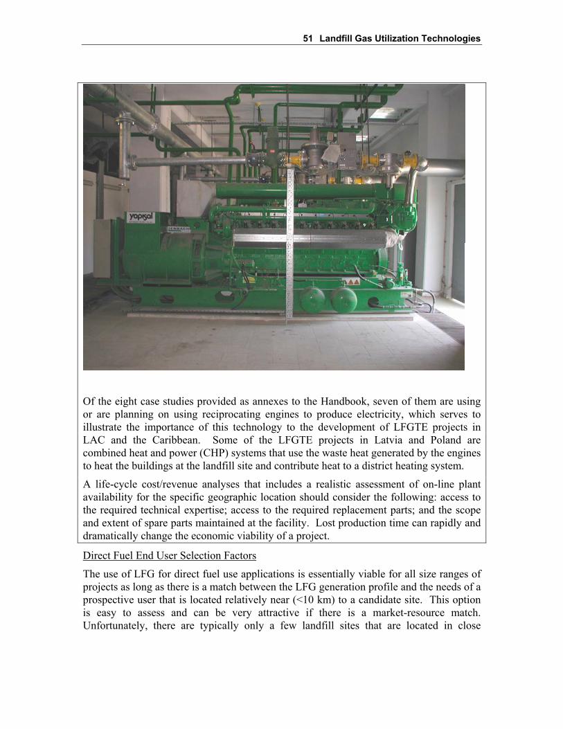
51 Landfill Gas Utilization Technologies
Of the eight case studies provided as annexes to the Handbook, seven of them are usingor are planning on using reciprocating engines to produce electricity, which serves toillustrate the importance of this technology to the development of LFGTE projects inLAC and the Caribbean. Some of the LFGTE projects in Latvia and Poland arecombined heat and power (CHP) systems that use the waste heat generated by the enginesto heat the buildings at the landfill site and contribute heat to a district heating system.
A life-cycle cost/revenue analyses that includes a realistic assessment of on-line plantavailability for the specific geographic location should consider the following: access tothe required technical expertise; access to the required replacement parts; and the scopeand extent of spare parts maintained at the facility. Lost production time can rapidly anddramatically change the economic viability of a project.
Direct Fuel End User Selection Factors
The use of LFG for direct fuel use applications is essentially viable for all size ranges ofprojects as long as there is a match between the LFG generation profile and the needs of aprospective user that is located relatively near (<10 km) to a candidate site. This optionis easy to assess and can be very attractive if there is a market-resource match.Unfortunately, there are typically only a few landfill sites that are located in close

52 Landfill Gas Utilization Technologies
proximity to a suitable fuel consumer. Factors to consider in determining suitability of anend user include:
• location of consumer to determine the length and location of a pipeline;
• energy requirements of user in terms of quantity and quality;
• daily and seasonal energy use profile of the prospective market;
• off-gas emission and treatment;
• costs associated with gas treatment, pipeline, and conversion of equipment to utilizeLFG;
• operating and maintenance costs; and
• cost of alternative fuels.
Each of these items must be evaluated for the conditions specific to the potential projectsite to determine the technical feasibility and financial viability of the project. Generally,the end user must consume large volumes of energy on a year round basis and be locatedin close proximity to the site to achieve an adequate return on investment for this type ofLFGTE project development. End users with large daily and/or seasonal fluctuations infuel demand are less desirable as LFG is produced in the Site at a relatively constant rateand there is little volume for storage of gas within the landfill site.