past cigre and emerging ieee guide documents on...
TRANSCRIPT

Past CIGRE and Emerging IEEE
Guide Documents on FCLs
Michael “Mischa” Steurer Leader Power Systems Research Group at FSU-CAPS
Email: [email protected], phone: 850-644-1629
Presented by W. Hassenzahl Advanced Energy Analysis
11th EPRI Superconductivity Conference
Oct 29, 2013, Houston, TX

Why FCLs ?
High short-circuit capacity
during normal operation
(low short-circuit impedance)
- Low voltage drops
- High power quality
- High steady-state and transient stability
- Low system pertubations
Low short-circuit capacity
during fault conditions
(high short-circuit impedance)
- Low thermal and mechanical strain
- Reduced breaker capacity
Design trade off in power systems
Optimal solution FCL
- Low impedance during normal operation
- Fast and effective current limitation
- Automatic and fast recovery
2
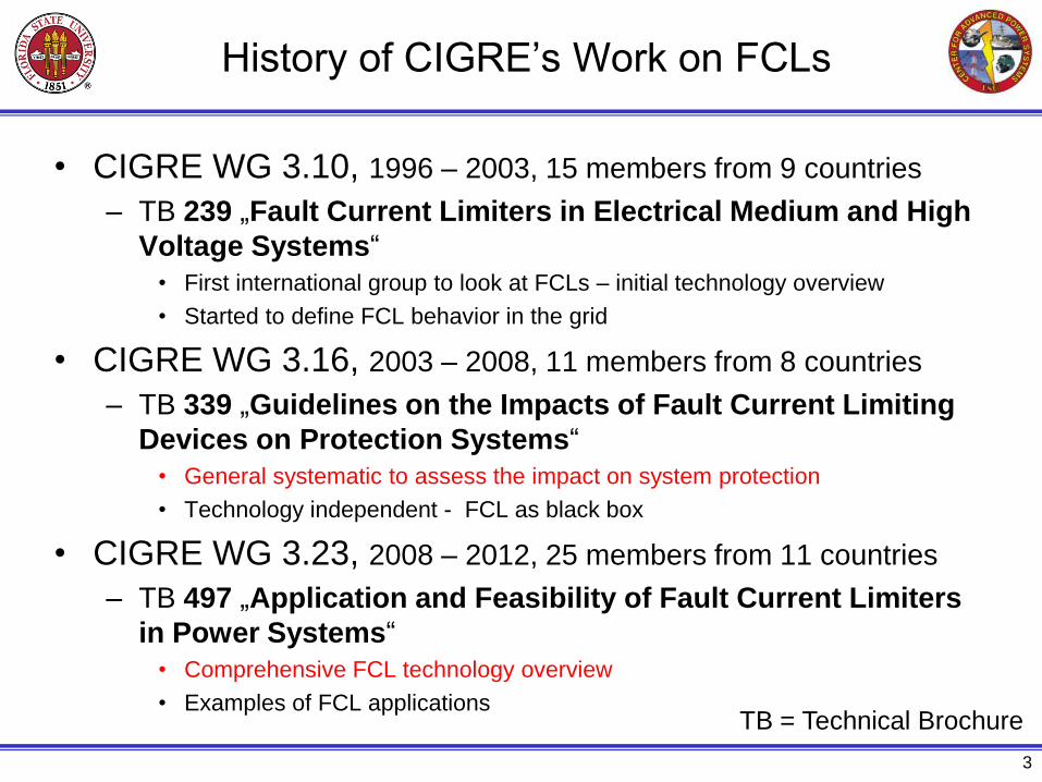
History of CIGRE’s Work on FCLs
• CIGRE WG 3.10, 1996 – 2003, 15 members from 9 countries
– TB 239 „Fault Current Limiters in Electrical Medium and High
Voltage Systems“
• First international group to look at FCLs – initial technology overview
• Started to define FCL behavior in the grid
• CIGRE WG 3.16, 2003 – 2008, 11 members from 8 countries
– TB 339 „Guidelines on the Impacts of Fault Current Limiting
Devices on Protection Systems“
• General systematic to assess the impact on system protection
• Technology independent - FCL as black box
• CIGRE WG 3.23, 2008 – 2012, 25 members from 11 countries
– TB 497 „Application and Feasibility of Fault Current Limiters
in Power Systems“
• Comprehensive FCL technology overview
• Examples of FCL applications
3
TB = Technical Brochure

Fault Current Limiting Measures
4
• Splitting into
sub grids
• Introducing a
higher voltage
range
• Splitting of
bus bars
• High
impedance
transformers
• Current
limiting
reactors
Emerging Concepts
• Superconductors
• Solid-State Devices
• Magnetic Effects
• Hybrid Systems
Topological
measures
Apparatus
measures
Permanent impedance increase
during nominal and fault conditions
Condition based impedance increase
Small impedance at nominal load
fast increase of impedance at fault
• Fuse based devices
(< 36 kV)
• Stand alone HV fuse
(< 1 kA)
• Commutating Current
Limiters (< 5 kA) • Sequential
tripping
Old term:
“passive” Old term:
“active”
Apparatus
measures
Topological
measures
Fault Current Limiting Devices
Fault Current LimitersPC37.302 adopted from CIGRE TB 497
Scope of IEEE
PC37.302
&
FCL must limit the
first peak

IEEE WG PC37.302
Guide for Fault Current Limiter Testing
• Established: June 2010, PAR expires Dec 2014
– Recognizing the need for general guidance on FCL testing to ease
market introduction
• Sponsors: IEEE Switchgear (PE/SWG) Committee
– Power & Energy Society/Substations (PE/SUB)
– Power Electronics Society/Standards Committee (PEL/SC)
• Balloting planned for Dec 2013
– Register and ballot via IEEE Standards Association
• Contact: Mischa Steurer
– [email protected], 850-644-1629
– Chair of IEEE WG PC37.302
– Former member of CIGRE WG A3.16, A3.23
5

IEEE WG PC37.302
Guide for Fault Current Limiter Testing
• Follows template/structure of other equipment testing
standards with clauses
3. Definitions
4. Introduction
5. Specification
6. Design Tests
7. Production (Routine) Tests
8. Field Tests
• Does not prescribe any specific value
– Provides parameter definitions for fully describing any FCL
behavior
• References numerous other IEEE and IEC standards for
applicable procedures, test setups, etc.
6
Major effort to develop general framework which maintains FCL
technology independence
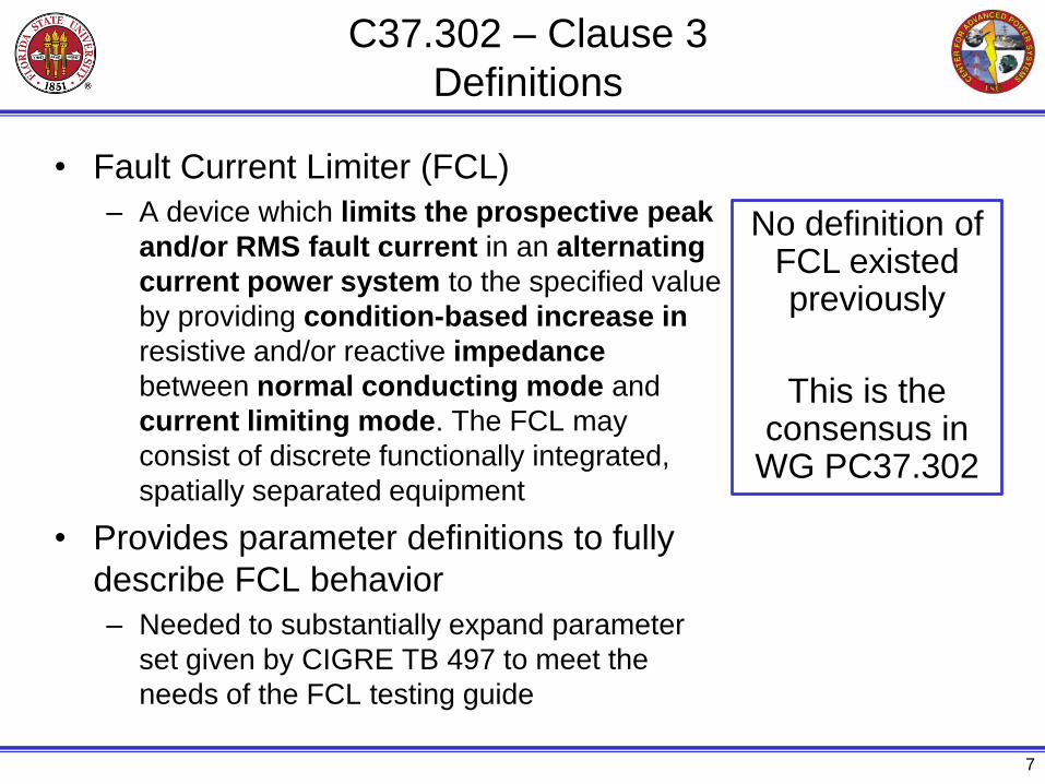
C37.302 – Clause 3
Definitions
• Fault Current Limiter (FCL)
– A device which limits the prospective peak
and/or RMS fault current in an alternating
current power system to the specified value
by providing condition-based increase in
resistive and/or reactive impedance
between normal conducting mode and
current limiting mode. The FCL may
consist of discrete functionally integrated,
spatially separated equipment
• Provides parameter definitions to fully
describe FCL behavior
– Needed to substantially expand parameter
set given by CIGRE TB 497 to meet the
needs of the FCL testing guide
7
No definition of FCL existed previously
This is the consensus in
WG PC37.302

C37.302 – Clause 3
Definitions – FCL modes
• C mode: normal conducting
– the FCL is in its low
impedance state
• CL mode: current limiting
– generally, the FCL is in
its high impedance state
– some technologies may
constantly transition between
high and low impedance
during the current limiting phase
• I mode: interruption
– the FCL has interrupted the fault
current flow (if applicable)
– Transitions to and from other
modes: IC, CLI, ICL
8
C mode
CL mode
ip,max
ip,LT
tk,CL
tLT
RI*22
max,kI*22
Prospective currentLimited current
I mode

C37.302 – Clause 4
FCL Technical Principles
• Treats FCL as black box
– Refers to CIGRE TB 497 for technology
overview in open literature
• FCL types consistent with TB 497
– A1: behavior with a current waveform that can
be accurately described by power
frequency and DC components after
transitioning into CL mode
– A2: current waveform, which after transitioning
into CL mode, requires additional
parameters or information during each
current loop besides power frequency and DC
components in order to be accurately
described
– B: A1 or A2 but with interruption by FCL
9
Example: Air core reactor
parallel with solid state switch
Example: Saturated iron
core type

Example: Type A1 – Resistive Behavior
10
Current through FCL
AND
Voltage across FCL
waveforms are parameterized
Fault inception
Fault clearing by
circuit breaker
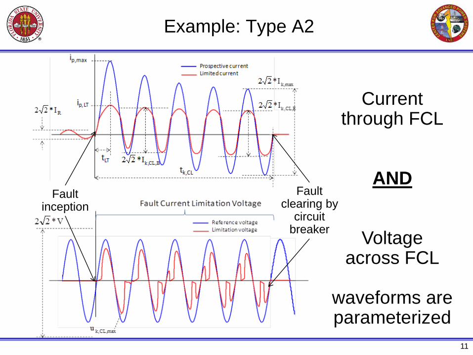
Example: Type A2
11
Fault inception
Fault clearing by
circuit breaker
Current through FCL
AND
Voltage across FCL
waveforms are parameterized

C37.302 – Clause 5
Specifications
• Provides parameter descriptions (no values) by
which FCLs may be specified & rated
– Electrical
• Prospective fault current, Rated power frequency, Rated
steady-state voltage drop, Rated losses, etc
– Physical and Operational
• Footprint, Height, Weight, Cryogenic system maintenance, etc.
– Environmental
• Proper thermal performance, Temperature regulation for
electronics, Transport conditions, Storage, etc.
– Safety
– Lifespan
12

C37.302 – Clause 5
Specifications – Recovery Process
• Provides guidance on how to parameterize the fault
current limitation and recovery process
• Technology
independent;
applicable to
all types of
FCLs
A1, A2, B
13
FCL in CL
mode limiting fault
current
Pa
rtia
l re
co
ve
ry p
roce
ss
Time
tpr
FCL is CL
mode recovered
Fault
inception Fault cleared
with load current
without
load current
FCL in CL mode, ready to limit
rated fault current
tr
FCL in C mode, ready to
limit rated fault current and enter CCL transition
trR
FCL is C mode
recovered
and ready to
carry below rated
continuous
current
and ready to carry
up to rated continuous
current
and ready
to carry up to rated
continuous
current
and ready to
carry below rated
continuous
current
tprR
with fault
current
FCL in
C mode ready to
limit
with
load current
FCL is fully
recovered
FCL is CL mode
rated recovered
tk,CL
tda
FC
L in
C m
od
e

C37.302 – Clause 6
Design Tests
• Voltage Withstand: Power Frequency,
Lightning Impulse, Switching Impulse,
Chopped-Wave, Partial Discharge
• Current Withstand: Continuous, Surge,
Short-Time and Peak Withstand
• Harmonic Distortion
• EMC, Audible Sound, Seismic, Visual
Inspection
• Short-circuit current limitation
• Recovery
• FCL Technology-Specific
14
Similar to other
equipment
FCL specific

Short-Circuit Current Limitation Test
15
G
Generator
FCL
Digital recorder
LoadLine CB
PT
CT
External
bypass CB
Short Circuit
CB
PT
Test
number
Applied current condition Duration Remark
1 Rated continuous current
of FCL (Ir)
3 sec. minimum To verify the expected insertion
impedance
2 Rated maximum
prospective short-circuit
current of FCL (ip,max,
ik,max )
10 cycles To verify the rated limited short circuit
withstand current of the FCL during
peak and RMS current limiting action
3 Rated continuous current
of FCL (Ir)
twice the expected
recovery time To verify the recovery time. The
duration should be long enough to
ensure recovery.
4 Rated maximum
prospective short-circuit
current of FCL (ip,max,
ik,max )
10 cycles To repeat test 2
1
Test Circuit
Example of test Sequence

Conclusions
• CIGRE TB 239, 339, and 497 provide very good
overview on FCL technologies, applications, and
power system impact
• IEEE C37.302 will provide the first guide for testing
– Substantially expanded the definitions of waveforms and
associated parameters to adequately describe FCL
behavior
– Defines a framework for FCL recovery
– Maintains technology independence
• Possible topic for next WG
– Guide for Application of FCLs in Power Systems
16