undercarriage installation...
TRANSCRIPT
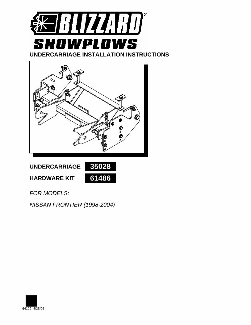
UNDERCARRIAGE INSTALLATION INSTRUCTIONS
UNDERCARRIAGE
HARDWARE KIT
FOR MODELS:
NISSAN FRONTIER (1998-2004)
64122 4/25/06
35028 61486
INSTALLATION INSTRUCTIONS
64122 (35028) 4/25/06 2 OF 4
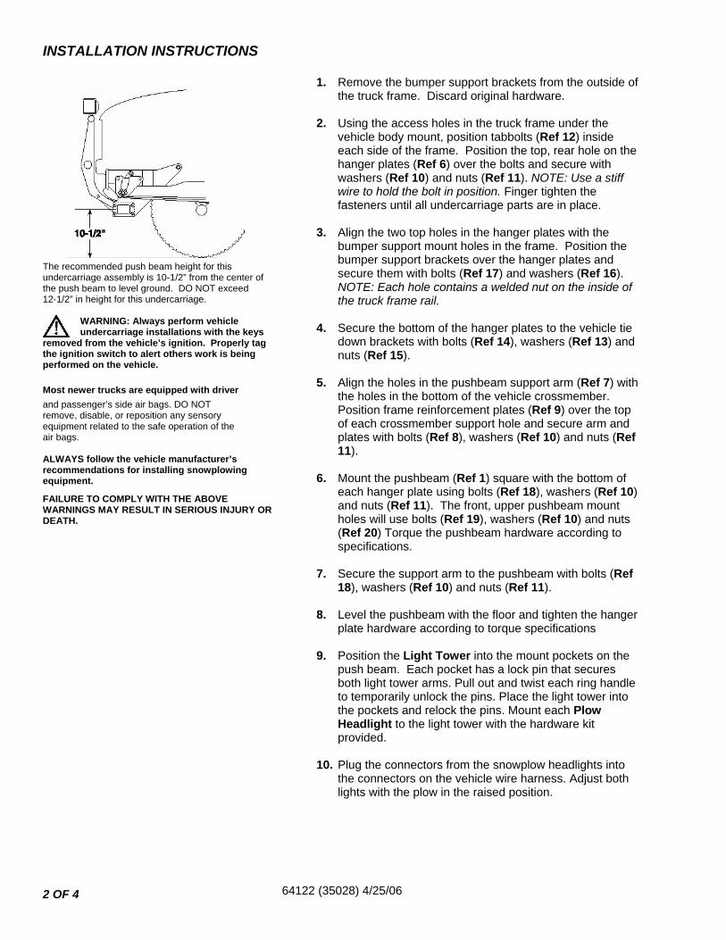
The recommended push beam height for this undercarriage assembly is 10-1/2” from the center of the push beam to level ground. DO NOT exceed 12-1/2” in height for this undercarriage.
WARNING: Always perform vehicle undercarriage installations with the keys
removed from the vehicle’s ignition. Properly tag the ignition switch to alert others work is being performed on the vehicle.
Most newer trucks are equipped with driver and passenger’s side air bags. DO NOT remove, disable, or reposition any sensory equipment related to the safe operation of the air bags. ALWAYS follow the vehicle manufacturer’s recommendations for installing snowplowing equipment.
FAILURE TO COMPLY WITH THE ABOVE WARNINGS MAY RESULT IN SERIOUS INJURY OR DEATH.
1. Remove the bumper support brackets from the outside of the truck frame. Discard original hardware.
2. Using the access holes in the truck frame under the
vehicle body mount, position tabbolts (Ref 12) inside each side of the frame. Position the top, rear hole on the hanger plates (Ref 6) over the bolts and secure with washers (Ref 10) and nuts (Ref 11). NOTE: Use a stiff wire to hold the bolt in position. Finger tighten the fasteners until all undercarriage parts are in place.
3. Align the two top holes in the hanger plates with the
bumper support mount holes in the frame. Position the bumper support brackets over the hanger plates and secure them with bolts (Ref 17) and washers (Ref 16). NOTE: Each hole contains a welded nut on the inside of the truck frame rail.
4. Secure the bottom of the hanger plates to the vehicle tie
down brackets with bolts (Ref 14), washers (Ref 13) and nuts (Ref 15).
5. Align the holes in the pushbeam support arm (Ref 7) with
the holes in the bottom of the vehicle crossmember. Position frame reinforcement plates (Ref 9) over the top of each crossmember support hole and secure arm and plates with bolts (Ref 8), washers (Ref 10) and nuts (Ref 11).
6. Mount the pushbeam (Ref 1) square with the bottom of
each hanger plate using bolts (Ref 18), washers (Ref 10) and nuts (Ref 11). The front, upper pushbeam mount holes will use bolts (Ref 19), washers (Ref 10) and nuts (Ref 20) Torque the pushbeam hardware according to specifications.
7. Secure the support arm to the pushbeam with bolts (Ref
18), washers (Ref 10) and nuts (Ref 11). 8. Level the pushbeam with the floor and tighten the hanger
plate hardware according to torque specifications 9. Position the Light Tower into the mount pockets on the
push beam. Each pocket has a lock pin that secures both light tower arms. Pull out and twist each ring handle to temporarily unlock the pins. Place the light tower into the pockets and relock the pins. Mount each Plow Headlight to the light tower with the hardware kit provided.
10. Plug the connectors from the snowplow headlights into
the connectors on the vehicle wire harness. Adjust both lights with the plow in the raised position.
UNDERCARRIAGE PARTS
64122 (35028) 4/25/06 3 OF 4
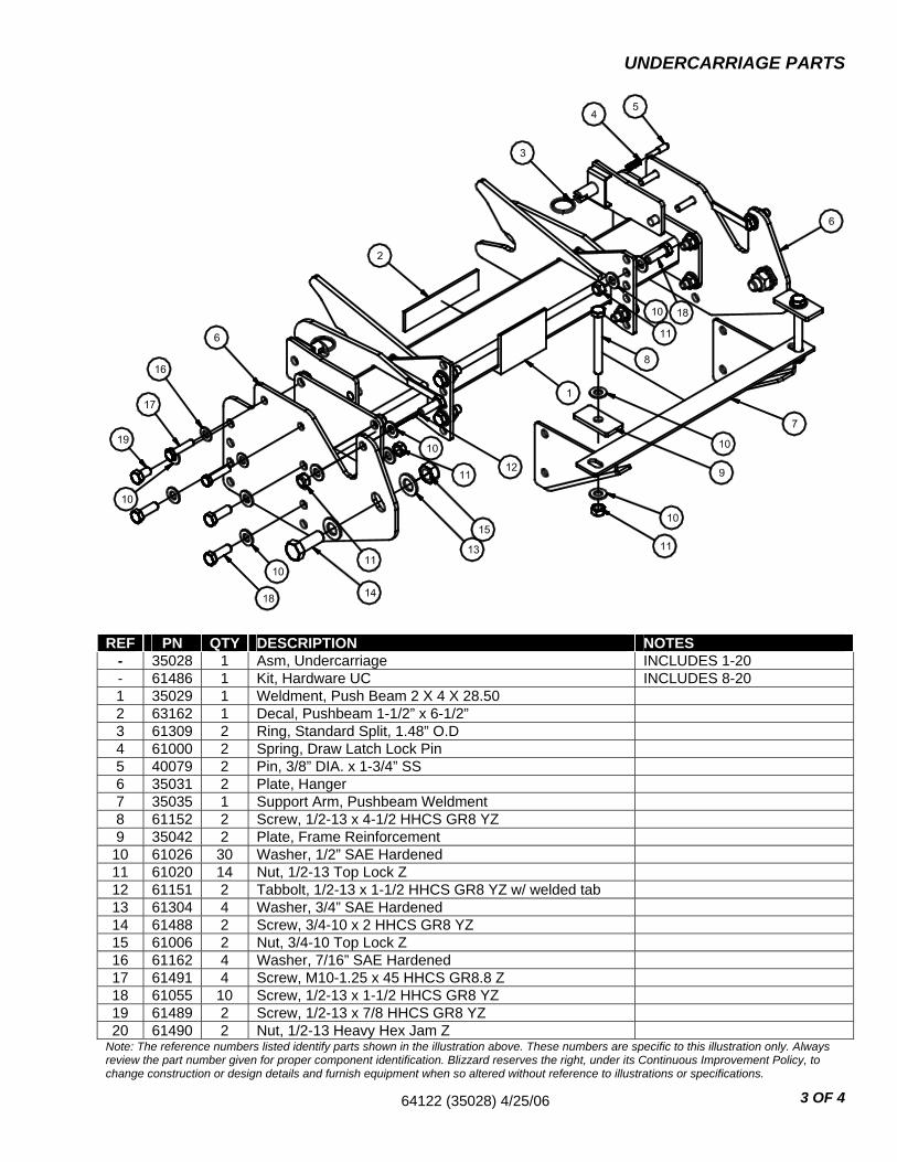
Note: The reference numbers listed identify parts shown in the illustration above. These numbers are specific to this illustration only. Always review the part number given for proper component identification. Blizzard reserves the right, under its Continuous Improvement Policy, to change construction or design details and furnish equipment when so altered without reference to illustrations or specifications.
REF PN QTY DESCRIPTION NOTES - 35028 1 Asm, Undercarriage INCLUDES 1-20 - 61486 1 Kit, Hardware UC INCLUDES 8-20 1 35029 1 Weldment, Push Beam 2 X 4 X 28.50 2 63162 1 Decal, Pushbeam 1-1/2” x 6-1/2” 3 61309 2 Ring, Standard Split, 1.48” O.D 4 61000 2 Spring, Draw Latch Lock Pin 5 40079 2 Pin, 3/8” DIA. x 1-3/4” SS 6 35031 2 Plate, Hanger 7 35035 1 Support Arm, Pushbeam Weldment 8 61152 2 Screw, 1/2-13 x 4-1/2 HHCS GR8 YZ 9 35042 2 Plate, Frame Reinforcement
10 61026 30 Washer, 1/2” SAE Hardened 11 61020 14 Nut, 1/2-13 Top Lock Z 12 61151 2 Tabbolt, 1/2-13 x 1-1/2 HHCS GR8 YZ w/ welded tab 13 61304 4 Washer, 3/4” SAE Hardened 14 61488 2 Screw, 3/4-10 x 2 HHCS GR8 YZ 15 61006 2 Nut, 3/4-10 Top Lock Z 16 61162 4 Washer, 7/16” SAE Hardened 17 61491 4 Screw, M10-1.25 x 45 HHCS GR8.8 Z 18 61055 10 Screw, 1/2-13 x 1-1/2 HHCS GR8 YZ 19 61489 2 Screw, 1/2-13 x 7/8 HHCS GR8 YZ 20 61490 2 Nut, 1/2-13 Heavy Hex Jam Z
64122 (35028) 4/25/06 4 OF 4
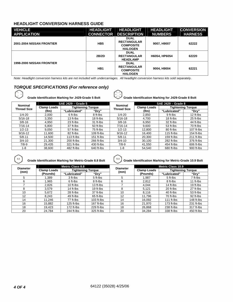
HEADLIGHT CONVERSION HARNESS GUIDE
Note: Headlight conversion harness kits are not included with undercarriages. All headlight conversion harness kits sold separately.
TORQUE SPECIFICATIONS (For reference only)
Grade Identification Marking for J429-Grade 5 Bolt Grade Identification Marking for J429-Grade 8 Bolt
SAE J429 – Grade 5 SAE J429 – Grade 8 Tightening Torque Tightening Torque Nominal
Thread Size Clamp Loads (lbs) “Lubricated” “Dry”
Nominal Thread Size Clamp Loads
(lbs) “Lubricated” “Dry” 1/4-20 2,000 6 ft-lbs 8 ft-lbs 1/4-20 2,850 9 ft-lbs 12 ft-lbs
5/16-18 3,350 13 ft-lbs 18 ft-lbs 5/16-18 4,700 18 ft-lbs 25 ft-lbs 3/8-16 4,950 23 ft-lbs 31 ft-lbs 3/8-16 6,950 32 ft-lbs 44 ft-lbs
7/16-14 6,800 37 ft-lbs 50 ft-lbs 7/16-14 9,600 53 ft-lbs 70 ft-lbs 1/2-13 9,050 57 ft-lbs 75 ft-lbs 1/2-13 12,800 80 ft-lbs 107 ft-lbs
9/16-12 11,600 82 ft-lbs 109 ft-lbs 9/16-12 16,400 115 ft-lbs 154 ft-lbs 5/8-11 14,500 113 ft-lbs 151 ft-lbs 5/8-11 20,300 159 ft-lbs 211 ft-lbs 3/4-10 21,300 200 ft-lbs 266 ft-lbs 3/4-10 30,100 282 ft-lbs 376 ft-lbs 7/8-9 29,435 321 ft-lbs 430 ft-lbs 7/8-9 41,550 454 ft-lbs 606 ft-lbs 1-8 38,600 482 ft-lbs 640 ft-lbs 1-8 54,540 680 ft-lbs 900 ft-lbs
Grade Identification Marking for Metric-Grade 8.8 Bolt Grade Identification Marking for Metric-Grade 10.9 Bolt
Metric Class 8.8 Metric Class 10.9 Tightening Torque Tightening Torque Diameter
(mm) Clamp Loads (Pounds) “Lubricated” “Dry”
Diameter (mm) Clamp Loads
(Pounds) “Lubricated” “Dry” 5 1,389 3 ft-lbs 5 ft-lbs 5 1,987 5 ft-lbs 7 ft-lbs 6 1,965 6 ft-lbs 8 ft-lbs 6 2,812 8 ft-lbs 11 ft-lbs 7 2,826 10 ft-lbs 13 ft-lbs 7 4,044 14 ft-lbs 19 ft-lbs 8 3,579 14 ft-lbs 19 ft-lbs 8 5,121 20 ft-lbs 27 ft-lbs
10 5,672 28 ft-lbs 37 ft-lbs 10 8,116 40 ft-lbs 53 ft-lbs 12 8,243 49 ft-lbs 65 ft-lbs 12 11,796 70 ft-lbs 92 ft-lbs 14 11,246 77 ft-lbs 103 ft-lbs 14 16,092 111 ft-lbs 148 ft-lbs 16 15,882 125 ft-lbs 167 ft-lbs 16 21,970 173 ft-lbs 231 ft-lbs 18 19,423 172 ft-lbs 229 ft-lbs 18 26,868 238 ft-lbs 317 ft-lbs 20 24,784 244 ft-lbs 325 ft-lbs 20 34,284 338 ft-lbs 450 ft-lbs
VEHICLE APPLICATION
HEADLIGHT CONNECTOR
HEADLIGHT DESCRIPTION
HEADLIGHT NUMBERS
CONVERSION HARNESS
2001-2004 NISSAN FRONTIER HB5 DUAL
RECTANGULAR COMPOSITE HALOGEN
9007, H9007 62222
2B/2D DUAL
RECTANGULAR HEADLAMP
H6054, HP6054 62220
1998-2000 NISSAN FRONTIER
HB1 DUAL
RECTANGULAR COMPOSITE HALOGEN
9004, H9004 62221