performance analysis and development of a semiconductor
TRANSCRIPT
Research ArticlePerformance Analysis and Development of a SemiconductorJunction Rectifier with Multicolor Coding for IndoorFarm Applications
E. D. Kanmani Ruby ,1 M. Umadevi,2 C. Kanmani Pappa,1 W. Edwin Santhkumar,3
P. Janani,1 and P. Shanmugasundaram 4
1Vel Tech Rangarajan Dr. Sagunthala R & D Institute of Science and Technology, Chennai, Tamilnadu, India2Er Perumal Manimegalai College of Engineering, Hosur, India3Sri Sakthi Institute of Engineering and Technology, Coimbatore, India4Mizan-Tepi University, Tepi, Ethiopia
Correspondence should be addressed to E. D. Kanmani Ruby; [email protected]
Received 4 August 2021; Revised 18 August 2021; Accepted 8 September 2021; Published 18 October 2021
Academic Editor: Samson Jerold Samuel Chelladurai
Copyright © 2021 E. D. Kanmani Ruby et al. (is is an open access article distributed under the Creative Commons AttributionLicense, which permits unrestricted use, distribution, and reproduction in any medium, provided the original work isproperly cited.
(is paper aims to build a smart lighting system with applications such as remote for controlling power supply and optimizingheat management in the metal body of the semiconductor diode and with a printed circuit board for agriculture. (e semi-conductor diode strips with multiple colors are lined up and configured as a LED lamp with proper casing and heat sink. It has adriver circuit with required power regulation that is able to control the intensity of light for photosynthesis and plant growthrequirements. (e system uses hydroponics to plant the water, thus decreasing the usage of fertilizers. (e entire system iscontrolled remotely using necessary communication interface application.
1. Introduction
(e most important mutable factor with respect to plantgrowth and development is light. (e lights in green houseapplication are advantages for plant growth research. (epurpose for using grow lights differs and includes increasinglight levels for plant photosynthesis or altering the photo-period [1].(e photoperiod is defined as the period of light aplant perceives. (e different lighting sources that growerscan use include incandescent (INC) lamps, tungsten-halo-gen lamps, fluorescent lamps, and high-intensity discharge(HID) lamps. Light-emitting diodes (LEDs) are fourth-generation lighting sources and are an emerging technologyin horticulture.
Lead-wire, surface-mounted, and high-power LEDs arethree main structural types. LEDs are solid-state semicon-ductors and when turned on or off, the action is instant andis about 70 percent from initial installation which can
operate up to 50,000 hours. It is not necessary to replacesingle diodes or lamps constantly because LEDs do not burnout. Factors such as design, materials used, and heat releaseaffect life expectancy. As for consumption of energy, LEDsare more efficient and use less energy than any other tra-ditional greenhouse lights [2]. In addition, operating costsand carbon emissions are lowered when using LEDs.
2. Related Works
(e authors in [1] have devised a new digital control strategythat is presented for a bridgeless single-stage multioutputAC/DC converter previously proposed as an semiconductordiode grow light. (e proposed control system can regulatethe output current flowing through each individual diodestring, perform power factor correction at the AC side, andprovide zero-voltage switching characteristics for all powersemiconductors, and the new method reduces conduction
HindawiAdvances in Materials Science and EngineeringVolume 2021, Article ID 6585680, 12 pageshttps://doi.org/10.1155/2021/6585680
losses associated with transformer windings and powersemiconductors by adaptively varying the DC bus voltage;thus, the new control system can result in superior transientresponse.
(e relationship between LEDs and plant growth withrespect to a small hydroponic plant is described in [3]. (eglobal population growth and the ongoing climate crisis poseimmense risk to the stable food supplies in the future. So, it isnecessary to develop a small hydroponic plant cultivationsystem to ensure supply of nutrients even in extreme cir-cumstances. To build a sustainable system, they have utilizedan LED lighting system together with conserved energygenerated by sunlight. Such hydroponic plant cultivationsystems have to operate at an affordable yet efficientprinciple.
(e authors in [4] specified how we can use Internet of(ings (IoT) and build smart garden systems. Internet of(ings (IoT) consists of devices that connect to the Internetand communicate with each other. It enables these devices tocollect and exchange data with a consumer. (is paperpresents an IoT-based Smart Garden with Weather Stationsystem, which can be used to monitor the growth of plantsevery day and predict the probability for raining. Manypeople interested in growing plants always forget to waterthe plants. Hence, in this study, the device is equipped with awater pump, where it can be monitored and controlled byusing a smartphone. In addition, the device also consists offour main sensors, which are a barometric pressure sensor, aDHT11 temperature and humidity sensor, a soil moisturesensor, and a light intensity module sensor.(e soil and lightintensity sensor is used to measure the value in percentages.Besides, two actuators, which are the water pump and LEDlight, can be used remotely or by using a button on thedevice. (e LED is purposely used to replicate the sunlightand make the plant grow faster. (is IoT-based SmartGarden with Weather Station System can record the dataand send the result to the user through the smartphoneapplication named “Blynk apps.” (is research is beneficial,and the system can be easily managed by all users such asresearchers, farmers, and children.
(e way the light supplementation can increase the cropyield in greenhouses by promoting photosynthesis and plantgrowth has been explained by the authors in [5]. However,the high energy costs associated with light supplementationare a predominant factor that limits development and profitimprovement of controlled environment agriculture.
In [6], the authors studied an effective way of light usagefor plant growth. (e light types included LED, grow light,and natural light. Investigated periods are germination andgrowth. A plant nursery of 1.2×1.2×1.5m in dimension wasused.(e structure was made up of PVC tubes. It was coveredby black canvas. (e system was controlled by a micro-controller. (e sensor module DHT22 detected both tem-perature and humidity. (e plant nursery was separated intotwo rooms for LED and grow light testing. Cooling pads andwater dispenser were used for the cooling system. A fan wasinstalled for flowing air. (e plant was watered automatically.From the experimental results, it was observed that the plantunder LED light had the fastest rate of germination.
In [7], the current agriculture and its advancement areexplained, with sustainable food production and security in ademographically obese world, and considered to be thechallenging issue. Different technologies were employed toenable farming practices to adapt and build resilience againstirregular microclimate shifts. Alternate farming technolo-gies like hydroponic culture technique and integration ofsmart artificial light and IoT system are deemed promisingsolutions to the aforementioned problems.
(e authors in [8] discussed how to develop a smart LEDlighting system [8], which is remotely controlled by Androidapps via handheld devices, e.g., smartphones, tablets, and soforth. (e status of energy use is reflected by readingsdisplayed on a handheld device, and it is treated as a cri-terion in the lighting mode design of a system. (e wirelessdata communication is designed to operate in compliancewith the ZigBee standard, and signal processing on senseddata is made through a self-adaptive weighted data fusionalgorithm. A low variation in data fusion together with ahigh stability is experimentally demonstrated in this work.
In [9], the authors described how light-emitting diodes(LEDs) have tremendous potential as supplemental or sole-source lighting systems for crop production both on and offearth. (eir small size, durability, long-operating lifetime,wavelength specificity, relatively cool emitting surfaces, andlinear photon output with electrical input current makethese solid-state light sources ideal for use in plant lightingdesigns.
3. Designing of LEDs: Manufacturing Process
3.1. Frame Precuring for Die Bond. To begin, it all starts withthe precuring of the LED frames [1] in oven 1 for 1 hour at150 degrees. (is is because the metal becomes soft, and itwill be easy to do the die bond.
3.2. Expanding Crystal. Now, the LED crystals are taken;initially, they are all placed very close to each other, so acompression machine is used to expand the spaces betweenthem. Before that, the LED crystals should be exposed topolarized air for a couple of seconds.
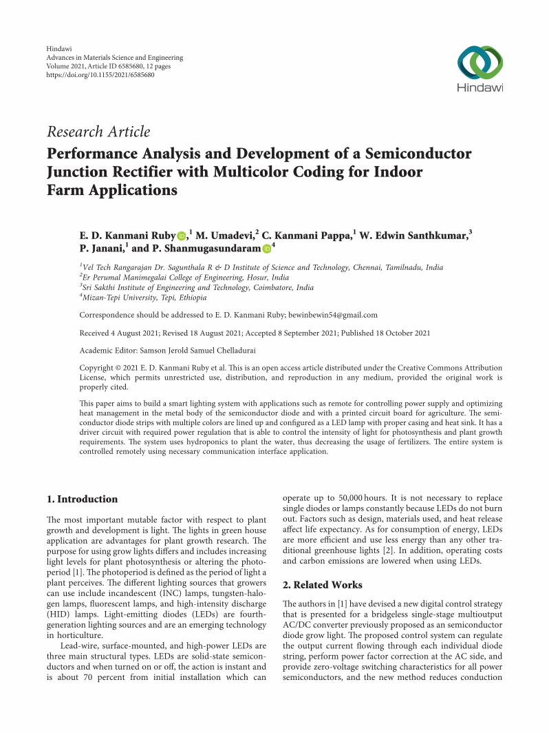
3.3. Die Bonding. Die bonding is a manufacturing processused in the packaging of semiconductors, as shown inFigure 1. It is the process of attaching a die (or chip) to asubstrate or package by epoxy or solder, also known as dieplacement or die attach.(e process starts with picking a diefrom a wafer or waffle pack and then placing it at a specificlocation on the substrate. (e die is placed into a previouslydispensed epoxy or placed into solder.
(e die-attach material plays a key role in the perfor-mance and reliability of mid, high, and super high-powerLEDs. [10] (e selection of the suitable die-attach materialfor a particular chip structure and application depends onseveral considerations. (ese include the packaging process(throughput and yield); performance (thermal dissipationand light output); reliability (lumen maintenance); and cost.Eutectic gold-tin, silver-filled epoxies, solder, silicone, and
2 Advances in Materials Science and Engineering
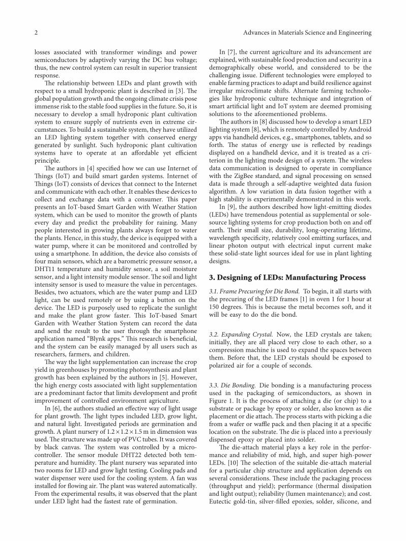
sintered materials have all been used for LED die-attach.(euse of a particular technology platform often results in trade-offs between different attributes. Mid- to super high-powerLEDs are operated at increasing current and power levels(for lighting and mobile ash applications, among others).(is trend has brought to the forefront the need for robustthermal dissipation. If the heat is not managed properly [11],the LED performance can degrade significantly, resulting inloss of radiant flux, increase in forward voltage, wavelengthshift, and consequently, reduced lifetime. Figures 1 and 2show the die-bonding machine and mechanism of diebonding, respectively.
3.4. Die-Bonded Frame for Curing. After the die bonding isperformed, the frames are again placed in oven 2 at 175degrees for 2 hours. (us, the LED gets well settled andbecomes rigid in place.
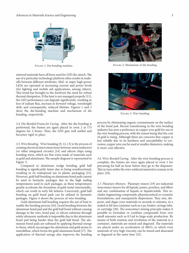
3.5.Wire Bonding. Wire bonding [9, 12, 13] is the process ofcreating electrical interconnections between semiconductors(or other integrated circuits) [14] and silicon chips usingbonding wires, which are fine wires made of materials suchas gold and aluminum.(e sample diagram is represented inFigure 3.
Compared to aluminum wedge bonding, gold ballbonding is significantly faster due to being nondirectional,resulting in its widespread use in plastic packaging [15].However, gold ball bonding on aluminum bond pads cannotbe used in hermetic packages due to the high sealingtemperatures used in such packages, as these temperaturesgreatly accelerate the formation of gold-metal intermetallic,which can result in early life failures. Conversely, gold ballbonding on gold bond pads can be utilized in hermeticpackages. Figure 4 shows the process of wire bonding.
Gold-aluminum ball bonding requires the use of heat toenable the bonding process [16]. Good bonding between thealuminum bond pad and the gold ball bond without causingdamage to the wire, bond pad, or silicon substrate throughsolely ultrasonic methods is impossible due to the aluminumbond pad being harder than the gold ball bond. (e alu-minum bond pads are softened by applying thermal energyto them, which encourages the aluminum and gold atoms tointerdiffuse, which forms the gold-aluminum bond [17].(eapplication of thermal energy also improves the bonding
process by eliminating organic contaminants on the surfaceof the bond pad. Recent transitioning in the wire bondingindustry has seen a preference in copper over gold for use inthe wire bonding process, with the reason being that the costof gold is rising. Although there are concerns that copper isless reliable due to its hardness and susceptibility to cor-rosion, copper wire can be used at smaller diameters, makingit more cost-effective.
3.6. Wire-Bonded Curing. After the wire-bonding process iscomplete, the frames are once again placed in oven 1 forprecuring for half an hour before they go to the dispenser.(is in turn settles the wire-solderedmaterial to remain in itsplace [18].
3.7. Planetary Mixture. Planetary mixers [19] are industrialnoncontact mixers for all liquids, pastes, powders, and fillersand any combination of liquids or liquids/solids. (is in-cludes engineering compounds, pharmaceutical or cosmeticformulations, and nanoparticle dispersions. (ey mix, dis-perse, and degas your materials in seconds to minutes, in asealed or lid-less container such as a jar, beaker, syringe tube,or cartridge [20]. (e noncontact mixing principle makes itpossible to formulate or combine compounds from verysmall amounts such as 0.5ml to large-scale production. Bymeans of both rotation and revolution of the material in acontainer, materials are mixed and degassed. (e materialsare placed under an acceleration of 400G, in which evenmaterials of very high viscosity can be mixed and deaeratedor degassed at the same time [21].
Figure 2: Mechanism of die bonding.
Figure 3: Wire bonding.
Figure 1: Die-bonding machine.
Advances in Materials Science and Engineering 3
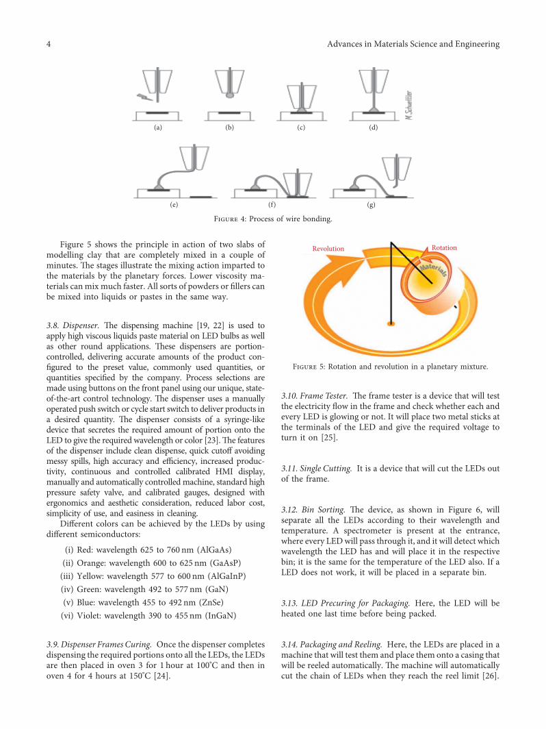
Figure 5 shows the principle in action of two slabs ofmodelling clay that are completely mixed in a couple ofminutes. (e stages illustrate the mixing action imparted tothe materials by the planetary forces. Lower viscosity ma-terials canmix much faster. All sorts of powders or fillers canbe mixed into liquids or pastes in the same way.
3.8. Dispenser. (e dispensing machine [19, 22] is used toapply high viscous liquids paste material on LED bulbs as wellas other round applications. (ese dispensers are portion-controlled, delivering accurate amounts of the product con-figured to the preset value, commonly used quantities, orquantities specified by the company. Process selections aremade using buttons on the front panel using our unique, state-of-the-art control technology. (e dispenser uses a manuallyoperated push switch or cycle start switch to deliver products ina desired quantity. (e dispenser consists of a syringe-likedevice that secretes the required amount of portion onto theLED to give the required wavelength or color [23].(e featuresof the dispenser include clean dispense, quick cutoff avoidingmessy spills, high accuracy and efficiency, increased produc-tivity, continuous and controlled calibrated HMI display,manually and automatically controlled machine, standard highpressure safety valve, and calibrated gauges, designed withergonomics and aesthetic consideration, reduced labor cost,simplicity of use, and easiness in cleaning.
Different colors can be achieved by the LEDs by usingdifferent semiconductors:
(i) Red: wavelength 625 to 760 nm (AlGaAs)(ii) Orange: wavelength 600 to 625 nm (GaAsP)(iii) Yellow: wavelength 577 to 600 nm (AlGaInP)(iv) Green: wavelength 492 to 577 nm (GaN)(v) Blue: wavelength 455 to 492 nm (ZnSe)(vi) Violet: wavelength 390 to 455 nm (InGaN)
3.9. Dispenser Frames Curing. Once the dispenser completesdispensing the required portions onto all the LEDs, the LEDsare then placed in oven 3 for 1 hour at 100°C and then inoven 4 for 4 hours at 150°C [24].
3.10. Frame Tester. (e frame tester is a device that will testthe electricity flow in the frame and check whether each andevery LED is glowing or not. It will place two metal sticks atthe terminals of the LED and give the required voltage toturn it on [25].
3.11. Single Cutting. It is a device that will cut the LEDs outof the frame.
3.12. Bin Sorting. (e device, as shown in Figure 6, willseparate all the LEDs according to their wavelength andtemperature. A spectrometer is present at the entrance,where every LEDwill pass through it, and it will detect whichwavelength the LED has and will place it in the respectivebin; it is the same for the temperature of the LED also. If aLED does not work, it will be placed in a separate bin.
3.13. LED Precuring for Packaging. Here, the LED will beheated one last time before being packed.
3.14. Packaging and Reeling. Here, the LEDs are placed in amachine that will test them and place them onto a casing thatwill be reeled automatically. (e machine will automaticallycut the chain of LEDs when they reach the reel limit [26].
(a) (b) (c) (d)
(e) (f) (g)
Figure 4: Process of wire bonding.
Revolution Rotation
Figure 5: Rotation and revolution in a planetary mixture.
4 Advances in Materials Science and Engineering

3.15. Packing. (e reels are placed in a cover and then usinga vacuum, the air is sucked out and sealed.
4. LED Grow Lights
An LED grow light is an electric light source, which helpsplants to grow [1–5]. Grow lights either attempt to provide alight spectrum similar to that of the sun or a spectrum that ismore tailored to the needs of the plants being cultivated.Outdoor conditions are mimicked with varying colors,temperatures, and spectral outputs from the grow light, aswell as varying the intensity of the lamps. Depending on thetype of plants being cultivated, the stage of cultivation, andthe photoperiod required by the plants, the specific ranges ofspectrum, luminous efficacy, and color temperature areconsidered to be desirable parameters for some specificplants.
Energy-efficient LED grow lights are the lighting of thefuture of agriculture [6]. (ey not only are economic in theiruse, but produce better plants as well, in comparison to alltraditional lighting options.
LEDs outperform incandescent lights in many ways,especially when it comes to energy efficiency. According toEnergy Star, the LEDs can save energy at a rate of 90 percentmore than incandescent bulbs. (e way LED lighting worksis when the light source is turned on, it is directional. (ismeans that the LED light aims in a certain direction toprovide illumination. But in a compact fluorescent lamp orCFL as well as incandescent bulbs, the light travels in alldirections, which decreases energy efficiency due todispersion of light unnecessarily. Not only do LEDs make asmarter choice for the environment then, but for our walletsas well. Most LED lights will last about 50,000 hours.
4.1. LED Grow Lights. (ese do not solely have to be LEDlights. We may also choose to grow your plants with high-intensity discharge lights or HIDs, fluorescents, and in-candescent grow lights. No matter which we choose, growlights generate the right amount of light, so a plant canphotosynthesize [27]. (is means of conversion gives theplant the energy. Most grow lights are electric, and all areartificial. Plant owners will use grow lights if a plant needs anextra light source besides the sun or if the plant cannot getaccess to the sun for any reason. For instance, maybe wegrow a plant in a cubicle, grow lights, although artificial, tryto mimic the sun as naturally as possible. In doing this, wetypically have a varying light spectrum available for our grow
lights. Besides the color spectrum, it is also possible to havecontrol over the color temperature and the luminous efficacywith grow lights.
5. Hydroponics
Hydroponics is a method of growing plants indoors withoutusing any soil [3–5, 7]. Instead of pulling mineral nutrientsneeded for growth from the ground, plants get all of theirnutrition through a nutrient solution supplied to their roots.Hydroponics works in a variety of scenarios from growing asmall collection of herbs in a kitchen all the way up tonumerous plants in a large-scale commercial operation.People with limited or no outdoor space, such as urbanresidents, apartment dwellers, or renters who cannot have anoutdoor garden, find hydroponic growing especially useful[28–33].
(e advantages of hydroponics are as follows [8, 9, 34]:firstly, it requires far lesser space that plants grown in soil,and the roots do not have to spread out to search for nu-trients and moisture as in hydroponics water, and nutrientsare delivered to the roots directly, either intermittently orconstantly. Secondly, it conserves a lot of water whencompared to soil growing plants. (irdly, it requires lesslabor, as it does not require tilling, weeding, and herbicideand insecticide application, as the user is just required tomake sure to change water time to time. Fourthly, as it doesnot require artificial fertilizers, the plants are more naturaland organic and have higher quality. Finally, the reason tochoose this technology is that the customer using this devicecan grow his/her own plants or vegetables anywhere theywant, and also it is very easy to control it as it is equippedwith Wi-Fi and its own app with easy settings. It grows theplants with the highest quality without compromising on thebest form of its organic, natural, and nutritious state [35].
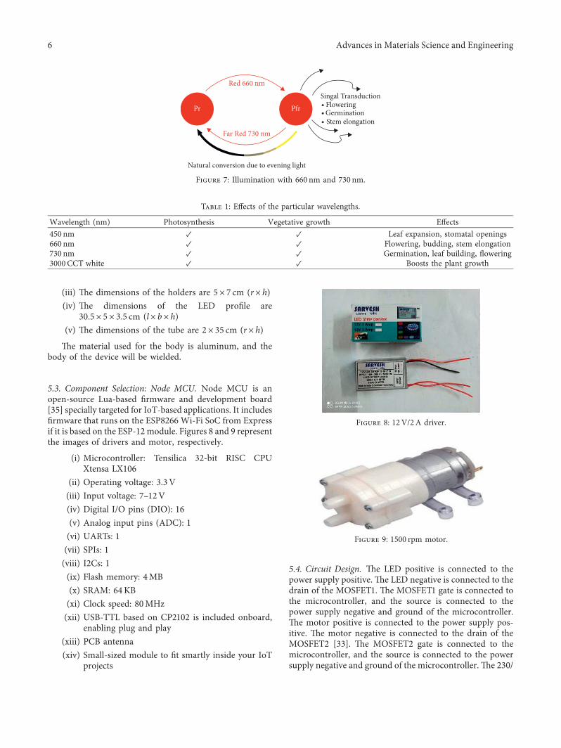
5.1. Selection of Wavelength. (e LEDs selected are 450 nm,660 nm, 730 nm, and 3000CCT [9]. (e amount of lightaffects the photosynthesis process in the plant. (is processis a photochemical reaction within the chloroplasts of theplant cells, in which CO is converted into carbohydrateunder the influence of the light energy. (e spectral com-position of the different wavelength regions (blue, green,yellow, red, far red, or invisible, e.g., UV or IR) is importantfor the growth, shape, development, and flowering (pho-tomorphogenesis) of the plant. Figure 7 shows the illumi-nation with various wavelengths. Table 1 shows variouswavelengths, vegetative growth, and its effects.
5.2. Design of the Body. (e body of the design consists of 2plant holders, a container with partitions for the compo-nents, a lid to close the container, and a tube to hold andsupport the LED profile.
(i) (e dimensions of the container are 35× 20×10 cm(l× b× h)
(ii) (e dimensions of the plant container are30×17×10 cm (l× b× h)
Figure 6: Mechanism inside a bin-sorting machine.
Advances in Materials Science and Engineering 5
(iii) (e dimensions of the holders are 5× 7 cm (r× h)(iv) (e dimensions of the LED profile are
30.5× 5× 3.5 cm (l× b× h)(v) (e dimensions of the tube are 2× 35 cm (r× h)
(e material used for the body is aluminum, and thebody of the device will be wielded.
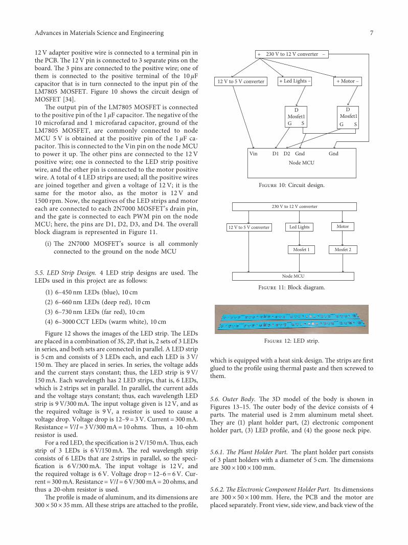
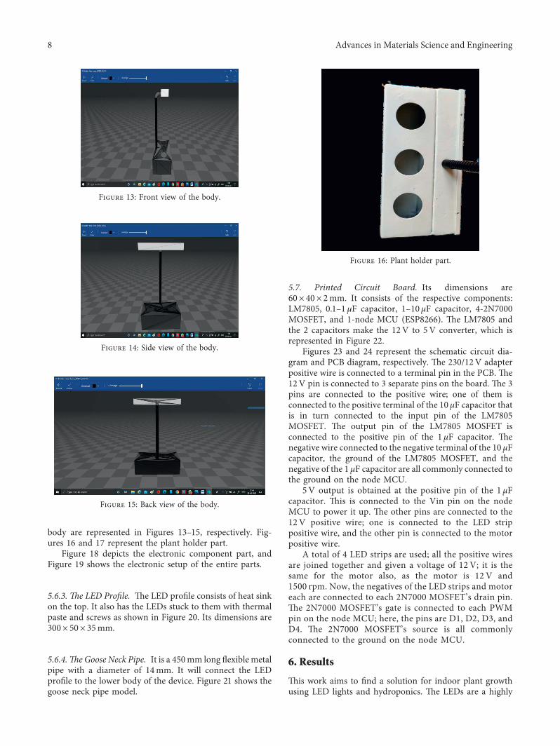
5.3. Component Selection: Node MCU. Node MCU is anopen-source Lua-based firmware and development board[35] specially targeted for IoT-based applications. It includesfirmware that runs on the ESP8266 Wi-Fi SoC from Expressif it is based on the ESP-12 module. Figures 8 and 9 representthe images of drivers and motor, respectively.
(i) Microcontroller: Tensilica 32-bit RISC CPUXtensa LX106
(ii) Operating voltage: 3.3 V(iii) Input voltage: 7–12V(iv) Digital I/O pins (DIO): 16(v) Analog input pins (ADC): 1(vi) UARTs: 1(vii) SPIs: 1(viii) I2Cs: 1(ix) Flash memory: 4MB(x) SRAM: 64KB(xi) Clock speed: 80MHz(xii) USB-TTL based on CP2102 is included onboard,
enabling plug and play(xiii) PCB antenna(xiv) Small-sized module to fit smartly inside your IoT
projects
5.4. Circuit Design. (e LED positive is connected to thepower supply positive. (e LED negative is connected to thedrain of the MOSFET1. (e MOSFET1 gate is connected tothe microcontroller, and the source is connected to thepower supply negative and ground of the microcontroller.(e motor positive is connected to the power supply pos-itive. (e motor negative is connected to the drain of theMOSFET2 [33]. (e MOSFET2 gate is connected to themicrocontroller, and the source is connected to the powersupply negative and ground of the microcontroller. (e 230/
Table 1: Effects of the particular wavelengths.
Wavelength (nm) Photosynthesis Vegetative growth Effects450 nm ✓ ✓ Leaf expansion, stomatal openings660 nm ✓ ✓ Flowering, budding, stem elongation730 nm ✓ ✓ Germination, leaf building, flowering3000CCT white ✓ ✓ Boosts the plant growth
Red 660 nm
Far Red 730 nm
Singal TransductionFloweringGerminationStem elongation
Pr Pfr
Natural conversion due to evening light
Figure 7: Illumination with 660 nm and 730 nm.
Figure 8: 12V/2A driver.
Figure 9: 1500 rpm motor.
6 Advances in Materials Science and Engineering
12V adapter positive wire is connected to a terminal pin inthe PCB. (e 12V pin is connected to 3 separate pins on theboard. (e 3 pins are connected to the positive wire; one ofthem is connected to the positive terminal of the 10 μFcapacitor that is in turn connected to the input pin of theLM7805 MOSFET. Figure 10 shows the circuit design ofMOSFET [34].
(e output pin of the LM7805 MOSFET is connectedto the positive pin of the 1 μF capacitor.(e negative of the10 microfarad and 1 microfarad capacitor, ground of theLM7805 MOSFET, are commonly connected to nodeMCU 5V is obtained at the positive pin of the 1 μF ca-pacitor. (is is connected to the Vin pin on the node MCUto power it up. (e other pins are connected to the 12 Vpositive wire; one is connected to the LED strip positivewire, and the other pin is connected to the motor positivewire. A total of 4 LED strips are used; all the positive wiresare joined together and given a voltage of 12 V; it is thesame for the motor also, as the motor is 12 V and1500 rpm. Now, the negatives of the LED strips and motoreach are connected to each 2N7000 MOSFET’s drain pin,and the gate is connected to each PWM pin on the nodeMCU; here, the pins are D1, D2, D3, and D4. (e overallblock diagram is represented in Figure 11.
(i) (e 2N7000 MOSFET’s source is all commonlyconnected to the ground on the node MCU
5.5. LED Strip Design. 4 LED strip designs are used. (eLEDs used in this project are as follows:
(1) 6–450 nm LEDs (blue), 10 cm(2) 6–660 nm LEDs (deep red), 10 cm(3) 6–730 nm LEDs (far red), 10 cm(4) 6–3000CCT LEDs (warm white), 10 cm
Figure 12 shows the images of the LED strip. (e LEDsare placed in a combination of 3S, 2P, that is, 2 sets of 3 LEDsin series, and both sets are connected in parallel. A LED stripis 5 cm and consists of 3 LEDs each, and each LED is 3V/150m. (ey are placed in series. In series, the voltage addsand the current stays constant; thus, the LED strip is 9V/150mA. Each wavelength has 2 LED strips, that is, 6 LEDs,which is 2 strips set in parallel. In parallel, the current addsand the voltage stays constant; thus, each wavelength LEDstrip is 9 V/300mA. (e input voltage given is 12V, and asthe required voltage is 9V, a resistor is used to cause avoltage drop. Voltage drop is 12–9� 3V. Current� 300mA.Resistance�V/I� 3V/300mA� 10 ohms. (us, a 10-ohmresistor is used.
For a red LED, the specification is 2V/150mA.(us, eachstrip of 3 LEDs is 6V/150mA. (e red wavelength stripconsists of 6 LEDs that are 2 strips in parallel, so the speci-fication is 6V/300mA. (e input voltage is 12V, andthe required voltage is 6V. Voltage drop� 12–6� 6V. Cur-rent� 300mA. Resistance�V/I� 6V/300mA� 20 ohms, andthus a 20-ohm resistor is used.
(e profile is made of aluminum, and its dimensions are300× 50× 35mm. All these strips are attached to the profile,
which is equipped with a heat sink design.(e strips are firstglued to the profile using thermal paste and then screwed tothem.
5.6. Outer Body. (e 3D model of the body is shown inFigures 13–15. (e outer body of the device consists of 4parts. (e material used is 2mm aluminum metal sheet.(ey are (1) plant holder part, (2) electronic componentholder part, (3) LED profile, and (4) the goose neck pipe.
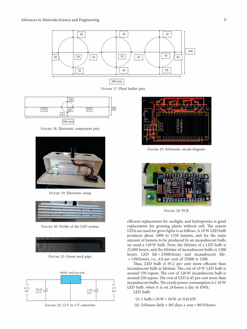
5.6.1. >e Plant Holder Part. (e plant holder part consistsof 3 plant holders with a diameter of 5 cm. (e dimensionsare 300×100×100mm.
5.6.2.>e Electronic Component Holder Part. Its dimensionsare 300× 50×100mm. Here, the PCB and the motor areplaced separately. Front view, side view, and back view of the
230 V to 12 V converter
12 V to 5 V converter
+ –
+ Led Lights – + Motor –
D DMosfet1G S
Mosfet1G S
Vin D1 D2 Gnd GndNode MCU
Figure 10: Circuit design.
230 V to 12 V converter
12 V to 5 V converter Led Lights Motor
Mosfet 1 Mosfet 2
Node MCU
Figure 11: Block diagram.
Figure 12: LED strip.
Advances in Materials Science and Engineering 7
body are represented in Figures 13–15, respectively. Fig-ures 16 and 17 represent the plant holder part.
Figure 18 depicts the electronic component part, andFigure 19 shows the electronic setup of the entire parts.
5.6.3. >e LED Profile. (e LED profile consists of heat sinkon the top. It also has the LEDs stuck to them with thermalpaste and screws as shown in Figure 20. Its dimensions are300× 50× 35mm.
5.6.4.>e Goose Neck Pipe. It is a 450mm long flexible metalpipe with a diameter of 14mm. It will connect the LEDprofile to the lower body of the device. Figure 21 shows thegoose neck pipe model.
5.7. Printed Circuit Board. Its dimensions are60× 40× 2mm. It consists of the respective components:LM7805, 0.1–1 μF capacitor, 1–10 μF capacitor, 4-2N7000MOSFET, and 1-node MCU (ESP8266). (e LM7805 andthe 2 capacitors make the 12V to 5V converter, which isrepresented in Figure 22.
Figures 23 and 24 represent the schematic circuit dia-gram and PCB diagram, respectively. (e 230/12V adapterpositive wire is connected to a terminal pin in the PCB. (e12V pin is connected to 3 separate pins on the board. (e 3pins are connected to the positive wire; one of them isconnected to the positive terminal of the 10 μF capacitor thatis in turn connected to the input pin of the LM7805MOSFET. (e output pin of the LM7805 MOSFET isconnected to the positive pin of the 1 μF capacitor. (enegative wire connected to the negative terminal of the 10 μFcapacitor, the ground of the LM7805 MOSFET, and thenegative of the 1 μF capacitor are all commonly connected tothe ground on the node MCU.
5V output is obtained at the positive pin of the 1 μFcapacitor. (is is connected to the Vin pin on the nodeMCU to power it up. (e other pins are connected to the12V positive wire; one is connected to the LED strippositive wire, and the other pin is connected to the motorpositive wire.
A total of 4 LED strips are used; all the positive wiresare joined together and given a voltage of 12 V; it is thesame for the motor also, as the motor is 12 V and1500 rpm. Now, the negatives of the LED strips and motoreach are connected to each 2N7000 MOSFET’s drain pin.(e 2N7000 MOSFET’s gate is connected to each PWMpin on the node MCU; here, the pins are D1, D2, D3, andD4. (e 2N7000 MOSFET’s source is all commonlyconnected to the ground on the node MCU.
6. Results
(is work aims to find a solution for indoor plant growthusing LED lights and hydroponics. (e LEDs are a highly
Figure 13: Front view of the body.
Figure 14: Side view of the body.
Figure 15: Back view of the body.
Figure 16: Plant holder part.
8 Advances in Materials Science and Engineering
efficient replacement for sunlight, and hydroponics is goodreplacement for growing plants without soil. (e reasonLEDs are used for grow lights is as follows. A 10W LED bulbproduces about 1000 to 1250 lumens, and for the sameamount of lumens to be produced by an incandescent bulb,we need a 120W bulb. Now, the lifetime of a LED bulb is25,000 hours, and the lifetime of incandescent bulbs is 1200hours. LED life� 25000 hours and incandescent life-� 1200 hours, i.e., 4.8 per cent of 25000 is 1200.
(us, LED bulb is 95.2 per cent more efficient thanincandescent bulb in lifetime. (e cost of 10W LED bulb isaround 550 rupees. (e cost of 120W incandescent bulb isaround 250 rupees. (e cost of LED is 45 per cent more thanincandescent bulbs.(e yearly power consumption is 1 10WLED bulb, when it is on 24 hours a day in kWh.
LED bulb:
(i) 1 bulb× 10W� 10W or 0.01 kW(ii) 24 hours daily× 365 days a year� 8670 hours
30
20 20
45 4550 50
30 30
20
10050
30
30
300 mm
Figure 17: Plant holder part.
300 mm
143
10
143148
50
Figure 18: Electronic component part.
Figure 19: Electronic setup.
Figure 20: Profile of the LED system.
Figure 21: Goose neck pipe.
++ +
–
+
–
10 uF25 V
1 uF10 v
5 V12 VDC DC
7805IC with heat sink
12
3
Figure 22: 12V to 5V converter.
Figure 23: Schematic circuit diagram.
Figure 24: PCB.
Advances in Materials Science and Engineering 9
(iii) 0.01 kW× 8760 hours� 87.6 kWh(iv) So, in one year 87.6 kWh is consumed.
Incandescent bulb:
(i) 7 bulbs are needed to run for 1 year continuously(ii) 7 bulb× 120W� 840W or 0.84 kW(iii) 24 hours daily× 365 days a year� 8670 hours(iv) 0.84 kW× 8760 hours� 7358.4 kWh(v) So, in one year, 7358.4 kWh is consumed. (us,
when compared, the LED bulb is 84 per cent moreefficient than the incandescent bulb. (is is thesolution that is achieved through this project. Fig-ure 25 shows the simulation result of the work.
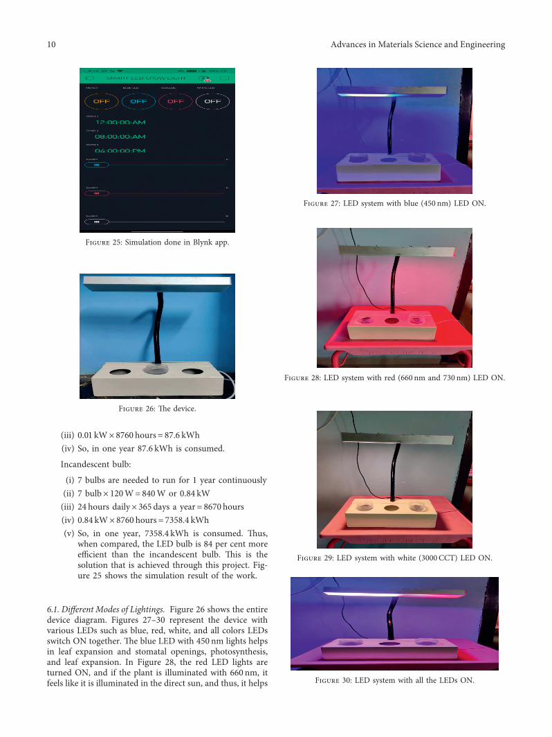
6.1. Different Modes of Lightings. Figure 26 shows the entiredevice diagram. Figures 27–30 represent the device withvarious LEDs such as blue, red, white, and all colors LEDsswitch ON together. (e blue LED with 450 nm lights helpsin leaf expansion and stomatal openings, photosynthesis,and leaf expansion. In Figure 28, the red LED lights areturned ON, and if the plant is illuminated with 660 nm, itfeels like it is illuminated in the direct sun, and thus, it helps
Figure 25: Simulation done in Blynk app.
Figure 26: (e device.
Figure 27: LED system with blue (450 nm) LED ON.
Figure 28: LED system with red (660 nm and 730 nm) LED ON.
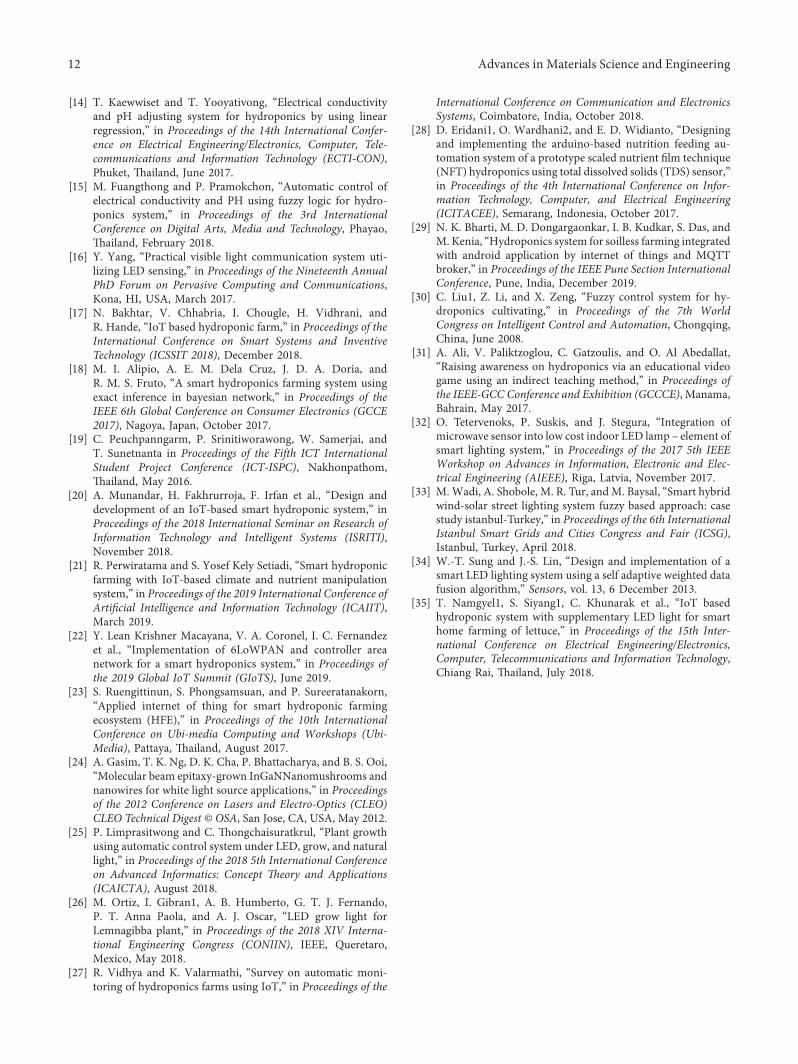
Figure 29: LED system with white (3000CCT) LED ON.
Figure 30: LED system with all the LEDs ON.
10 Advances in Materials Science and Engineering
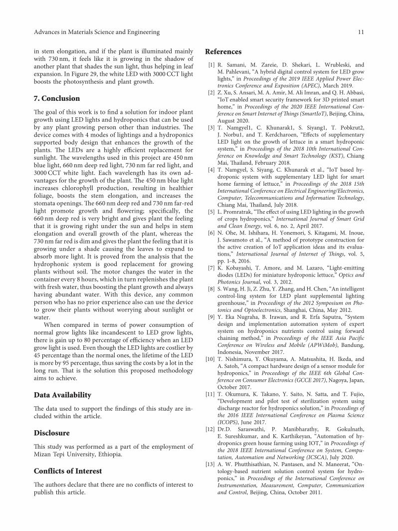
in stem elongation, and if the plant is illuminated mainlywith 730 nm, it feels like it is growing in the shadow ofanother plant that shades the sun light, thus helping in leafexpansion. In Figure 29, the white LED with 3000CCT lightboosts the photosynthesis and plant growth.
7. Conclusion
(e goal of this work is to find a solution for indoor plantgrowth using LED lights and hydroponics that can be usedby any plant growing person other than industries. (edevice comes with 4 modes of lightings and a hydroponicssupported body design that enhances the growth of theplants. (e LEDs are a highly efficient replacement forsunlight. (e wavelengths used in this project are 450 nmblue light, 660 nm deep red light, 730 nm far red light, and3000 CCT white light. Each wavelength has its own ad-vantages for the growth of the plant. (e 450 nm blue lightincreases chlorophyll production, resulting in healthierfoliage, boosts the stem elongation, and increases thestomata openings. (e 660 nm deep red and 730 nm far-redlight promote growth and flowering; specifically, the660 nm deep red is very bright and gives plant the feelingthat it is growing right under the sun and helps in stemelongation and overall growth of the plant, whereas the730 nm far red is dim and gives the plant the feeling that it isgrowing under a shade causing the leaves to expand toabsorb more light. It is proved from the analysis that thehydrophonic system is good replacement for growingplants without soil. (e motor changes the water in thecontainer every 8 hours, which in turn replenishes the plantwith fresh water, thus boosting the plant growth and alwayshaving abundant water. With this device, any commonperson who has no prior experience also can use the deviceto grow their plants without worrying about sunlight orwater.
When compared in terms of power consumption ofnormal grow lights like incandescent to LED grow lights,there is gain up to 80 percentage of efficiency when an LEDgrow light is used. Even though the LED lights are costlier by45 percentage than the normal ones, the lifetime of the LEDis more by 95 percentage, thus saving the costs by a lot in thelong run. (at is the solution this proposed methodologyaims to achieve.
Data Availability
(e data used to support the findings of this study are in-cluded within the article.
Disclosure
(is study was performed as a part of the employment ofMizan Tepi University, Ethiopia.
Conflicts of Interest
(e authors declare that there are no conflicts of interest topublish this article.
References
[1] R. Samani, M. Zareie, D. Shekari, L. Wrubleski, andM. Pahlevani, “A hybrid digital control system for LED growlights,” in Proceedings of the 2019 IEEE Applied Power Elec-tronics Conference and Exposition (APEC), March 2019.
[2] Z. Xu, S. Ansari, M. A. Amir, M. Ali Imran, and Q. H. Abbasi,“IoT enabled smart security framework for 3D printed smarthome,” in Proceedings of the 2020 IEEE International Con-ference on Smart Internet of>ings (SmartIoT), Beijing, China,August 2020.
[3] T. Namgyel1, C. Khunarak1, S. Siyang1, T. Pobkrut2,J. Norbu1, and T. Kerdcharoen, “Effects of supplementaryLED light on the growth of lettuce in a smart hydroponicsystem,” in Proceedings of the 2018 10th International Con-ference on Knowledge and Smart Technology (KST), ChiangMai, (ailand, February 2018.
[4] T. Namgyel, S. Siyang, C. Khunarak et al., “IoT based hy-droponic system with supplementary LED light for smarthome farming of lettuce,” in Proceedings of the 2018 15thInternational Conference on Electrical Engineering/Electronics,Computer, Telecommunications and Information Technology,Chiang Mai, (ailand, July 2018.
[5] L. Promratrak, “(e effect of using LED lighting in the growthof crops hydroponics,” International Journal of Smart Gridand Clean Energy, vol. 6, no. 2, April 2017.
[6] N. Ohe, M. Ishihara, H. Yonemori, S. Kitagami, M. Inoue,J. Sawamoto et al., “A method of prototype construction forthe active creation of IoT application ideas and its evalua-tions,” International Journal of Internet of >ings, vol. 5,pp. 1–8, 2016.
[7] K. Kobayashi, T. Amore, and M. Lazaro, “Light-emittingdiodes (LEDs) for miniature hydroponic lettuce,” Optics andPhotonics Journal, vol. 3, 2012.
[8] S. Wang, H. Ji, Z. Zhu, Y. Zhang, and H. Chen, “An intelligentcontrol-ling system for LED plant supplemental lightinggreenhouse,” in Proceedings of the 2012 Symposium on Pho-tonics and Optoelectronics, Shanghai, China, May 2012.
[9] Y. Eka Nugraha, B. Irawan, and R. Erfa Saputra, “Systemdesign and implementation automation system of expertsystem on hydroponics nutrients control using forwardchaining method,” in Proceedings of the IEEE Asia PacificConference on Wireless and Mobile (APWiMob), Bandung,Indonesia, November 2017.
[10] T. Nishimura, Y. Okuyama, A. Matsushita, H. Ikeda, andA. Satoh, “A compact hardware design of a sensor module forhydroponics,” in Proceedings of the IEEE 6th Global Con-ference on Consumer Electronics (GCCE 2017), Nagoya, Japan,October 2017.
[11] T. Okumura, K. Takano, Y. Saito, N. Satta, and T. Fujio,“Development and pilot test of sterilization system usingdischarge reactor for hydroponics solution,” in Proceedings ofthe 2016 IEEE International Conference on Plasma Science(ICOPS), June 2017.
[12] Dr.D. Saraswathi, P. Manibharathy, R. Gokulnath,E. Sureshkumar, and K. Karthikeyan, “Automation of hy-droponics green house farming using IOT,” in Proceedings ofthe 2018 IEEE International Conference on System, Compu-tation, Automation and Networking (ICSCA), July 2020.
[13] A. W. Phutthisathian, N. Pantasen, and N. Maneerat, “On-tology-based nutrient solution control system for hydro-ponics,” in Proceedings of the International Conference onInstrumentation, Measurement, Computer, Communicationand Control, Beijing, China, October 2011.
Advances in Materials Science and Engineering 11
[14] T. Kaewwiset and T. Yooyativong, “Electrical conductivityand pH adjusting system for hydroponics by using linearregression,” in Proceedings of the 14th International Confer-ence on Electrical Engineering/Electronics, Computer, Tele-communications and Information Technology (ECTI-CON),Phuket, (ailand, June 2017.
[15] M. Fuangthong and P. Pramokchon, “Automatic control ofelectrical conductivity and PH using fuzzy logic for hydro-ponics system,” in Proceedings of the 3rd InternationalConference on Digital Arts, Media and Technology, Phayao,(ailand, February 2018.
[16] Y. Yang, “Practical visible light communication system uti-lizing LED sensing,” in Proceedings of the Nineteenth AnnualPhD Forum on Pervasive Computing and Communications,Kona, HI, USA, March 2017.
[17] N. Bakhtar, V. Chhabria, I. Chougle, H. Vidhrani, andR. Hande, “IoT based hydroponic farm,” in Proceedings of theInternational Conference on Smart Systems and InventiveTechnology (ICSSIT 2018), December 2018.
[18] M. I. Alipio, A. E. M. Dela Cruz, J. D. A. Doria, andR. M. S. Fruto, “A smart hydroponics farming system usingexact inference in bayesian network,” in Proceedings of theIEEE 6th Global Conference on Consumer Electronics (GCCE2017), Nagoya, Japan, October 2017.
[19] C. Peuchpanngarm, P. Srinitiworawong, W. Samerjai, andT. Sunetnanta in Proceedings of the Fifth ICT InternationalStudent Project Conference (ICT-ISPC), Nakhonpathom,(ailand, May 2016.
[20] A. Munandar, H. Fakhrurroja, F. Irfan et al., “Design anddevelopment of an IoT-based smart hydroponic system,” inProceedings of the 2018 International Seminar on Research ofInformation Technology and Intelligent Systems (ISRITI),November 2018.
[21] R. Perwiratama and S. Yosef Kely Setiadi, “Smart hydroponicfarming with IoT-based climate and nutrient manipulationsystem,” in Proceedings of the 2019 International Conference ofArtificial Intelligence and Information Technology (ICAIIT),March 2019.
[22] Y. Lean Krishner Macayana, V. A. Coronel, I. C. Fernandezet al., “Implementation of 6LoWPAN and controller areanetwork for a smart hydroponics system,” in Proceedings ofthe 2019 Global IoT Summit (GIoTS), June 2019.
[23] S. Ruengittinun, S. Phongsamsuan, and P. Sureeratanakorn,“Applied internet of thing for smart hydroponic farmingecosystem (HFE),” in Proceedings of the 10th InternationalConference on Ubi-media Computing and Workshops (Ubi-Media), Pattaya, (ailand, August 2017.
[24] A. Gasim, T. K. Ng, D. K. Cha, P. Bhattacharya, and B. S. Ooi,“Molecular beam epitaxy-grown InGaNNanomushrooms andnanowires for white light source applications,” in Proceedingsof the 2012 Conference on Lasers and Electro-Optics (CLEO)CLEO Technical Digest © OSA, San Jose, CA, USA, May 2012.
[25] P. Limprasitwong and C. (ongchaisuratkrul, “Plant growthusing automatic control system under LED, grow, and naturallight,” in Proceedings of the 2018 5th International Conferenceon Advanced Informatics: Concept >eory and Applications(ICAICTA), August 2018.
[26] M. Ortiz, I. Gibran1, A. B. Humberto, G. T. J. Fernando,P. T. Anna Paola, and A. J. Oscar, “LED grow light forLemnagibba plant,” in Proceedings of the 2018 XIV Interna-tional Engineering Congress (CONIIN), IEEE, Queretaro,Mexico, May 2018.
[27] R. Vidhya and K. Valarmathi, “Survey on automatic moni-toring of hydroponics farms using IoT,” in Proceedings of the
International Conference on Communication and ElectronicsSystems, Coimbatore, India, October 2018.
[28] D. Eridani1, O. Wardhani2, and E. D. Widianto, “Designingand implementing the arduino-based nutrition feeding au-tomation system of a prototype scaled nutrient film technique(NFT) hydroponics using total dissolved solids (TDS) sensor,”in Proceedings of the 4th International Conference on Infor-mation Technology, Computer, and Electrical Engineering(ICITACEE), Semarang, Indonesia, October 2017.
[29] N. K. Bharti, M. D. Dongargaonkar, I. B. Kudkar, S. Das, andM. Kenia, “Hydroponics system for soilless farming integratedwith android application by internet of things and MQTTbroker,” in Proceedings of the IEEE Pune Section InternationalConference, Pune, India, December 2019.
[30] C. Liu1, Z. Li, and X. Zeng, “Fuzzy control system for hy-droponics cultivating,” in Proceedings of the 7th WorldCongress on Intelligent Control and Automation, Chongqing,China, June 2008.
[31] A. Ali, V. Paliktzoglou, C. Gatzoulis, and O. Al Abedallat,“Raising awareness on hydroponics via an educational videogame using an indirect teaching method,” in Proceedings ofthe IEEE-GCC Conference and Exhibition (GCCCE), Manama,Bahrain, May 2017.
[32] O. Tetervenoks, P. Suskis, and J. Stegura, “Integration ofmicrowave sensor into low cost indoor LED lamp – element ofsmart lighting system,” in Proceedings of the 2017 5th IEEEWorkshop on Advances in Information, Electronic and Elec-trical Engineering (AIEEE), Riga, Latvia, November 2017.
[33] M.Wadi, A. Shobole, M. R. Tur, andM. Baysal, “Smart hybridwind-solar street lighting system fuzzy based approach: casestudy istanbul-Turkey,” in Proceedings of the 6th InternationalIstanbul Smart Grids and Cities Congress and Fair (ICSG),Istanbul, Turkey, April 2018.
[34] W.-T. Sung and J.-S. Lin, “Design and implementation of asmart LED lighting system using a self adaptive weighted datafusion algorithm,” Sensors, vol. 13, 6 December 2013.
[35] T. Namgyel1, S. Siyang1, C. Khunarak et al., “IoT basedhydroponic system with supplementary LED light for smarthome farming of lettuce,” in Proceedings of the 15th Inter-national Conference on Electrical Engineering/Electronics,Computer, Telecommunications and Information Technology,Chiang Rai, (ailand, July 2018.
12 Advances in Materials Science and Engineering