performance analysis of bldc motor drive ... three phase voltage source is fed to the motor. a...
TRANSCRIPT

International Research Journal of Engineering and Technology (IRJET) e-ISSN: 2395-0056
Volume: 02 Issue: 06 | Sep-2015 www.irjet.net p-ISSN: 2395-0072
© 2015, IRJET ISO 9001:2008 Certified Journal Page 916
PERFORMANCE ANALYSIS OF BLDC MOTOR DRIVE USING PI AND
FUZZY LOGIC CONTROL SCHEME
Sudhanshu Mitra*Amit Ojha**
1 Mtech Scholar, Electrical Engineering Department, Manit Bhopal, India 2Assistant Professor, Electrical Engineering Department, Manit Bhopal, India
---------------------------------------------------------------------***---------------------------------------------------------------------Abstract - In this paper a comparative study on the
performance analysis of BLDC Motor is presented. The
mathematical model of the BLDC motor is developed
and it is used to examine the performance of the
controllers. Initially a PI controller is developed for
the speed control of the given BLDC motor. Then a
fuzzy logic based controller is developed. Through
extensive simulations it is observed that the
performance of fuzzy logic controller is slightly better
than PI controller.
Key Words: Modelling, Control schemes, PI, Fuzzy.
I. INTRODUCTION
Brushless DC Motors (BLDC) are widely used in many applications such as automotive, computer, industrial, aerospace etc. BLDC Motors have several advantages over brushed DC Motor. They have lower maintenance due to the elimination of the mechanical commutator and they have a high power density which makes them ideal for high torque to weight ratio applications. Compared to induction machines, they have lower inertia allowing for faster dynamic response to reference commands. Also, they are more efficient due to the permanent magnets which results in virtually zero rotor losses.
Due to overweighing merits of this motor, modeling is done in order to enhance the performance of the system. Modeling of BLDC Motor by using any particular control scheme is beneficial in carrying out the comprehensive simulation studies and further practical implementation. SIMULINK/ MATLAB environment provides accurate behaviour of the system in reality.
This paper presents a comparative study on the speed control of brushless DC Motor. The mathematical model of the BLDC Motor is developed and it is used to examine the performance of the controllers. Initially a PI controller is developed for the speed control of the BLDC Motor, than a Fuzzy Logic controller is developed for the same.
Through extensive simulations it is observed that the performance of Fuzzy Logic control scheme is better than the PI control scheme. Various simulation and experimental results are presented. The theoretical considerations are verified by simulation.
II. MODELLING OF BLDC MOTOR
BLDC motor which is modeled in this paper is a 3 phase 4 pole motor. A synchronous machine with Permanent magnet rotor can also be considered as BLDC motor and the only difference is the rotor construction due to which the dynamic characteristics of the machine changes and the three phase voltage source is fed to the motor. A sinusoidal square wave is not necessarily used as source or the other wave shape can also be used but it should not exceed the maximum voltage limits.
Fig.1 Equivalent circuit diagram of BLDC Motor
The modeled equations for the armature winding are as follows:- 𝑉𝑎 = R𝑖𝑎 + 𝐿 𝑑𝑖𝑎/𝑑𝑡 (1) 𝑉𝑏 = 𝑅𝑖𝑏 + 𝐿 𝑑𝑖𝑏/𝑑𝑡 (2) 𝑉𝑐 = 𝑅𝑖𝑐 + 𝐿 𝑑𝑖𝑐/𝑑𝑡 (3) Where L-armature selfinduction in [H] R-armature resistance in [Ω] Va, Vb, Vc –terminal phase voltage in [V] ia, ib, ic-motor input current in [A] ea, eb, ec-motor back-Emf in [V] Back-Emf of each phase has a phase difference of 120 electrical degrees and back- Emf and rotor position are related via some function. Equation of each phase for back-Emf is as follows:-
𝑒a= (𝜃𝑒)𝜔 (4) 𝑒b=(𝜃𝑒 − 2𝜋/3) (5)
International Research Journal of Engineering and Technology (IRJET) e-ISSN: 2395-0056
Volume: 02 Issue: 06 | Sep-2015 www.irjet.net p-ISSN: 2395-0072
© 2015, IRJET ISO 9001:2008 Certified Journal Page 917
𝑒c=(𝜃𝑒+2𝜋/3) (6)
Where Kw - back-Emf constant of one phase [V/rads-1] θe- rotor angle in electrical degree ω- rotor speed[rad.S-1] Rotor angel electrical [𝜃e] and Rotor angle mechanical [𝜃m] are related as:-
𝜃𝑒 = 𝑃/2𝜃𝑚 (7) Where P is the no of poles on rotor Thus the total electromagnetic torque Te in N-M can be expressed as follows:- 𝑇e = (𝑒𝑎𝑖𝑎+𝑒𝑏𝑖𝑏+𝑒𝑐𝑖𝑐)/ 𝜔 (8) The mechanical torque transferred to the motor shaft:- 𝑇𝑒 − 𝑇𝑙= 𝐽𝑑𝑤/𝑑𝑡+ 𝐵𝜔 (9) Where Tl = load torque [N-M] J = inertia of the rotor shaft [Kgm2] B = friction constant [Nms.rads-1]
III. BLDC MOTOR DRIVE CONTROL SCHEME
The block diagram of proposed BLDC Motor drive control scheme is shown in Fig. 2.
Fig.2 Block Diagram of BLDC Motor Drive Control Scheme
The basic block diagram of BLDC Motor control consist power converter, permanent magnet- synchronous machine (PMSM) sensors, and control algorithm. Three phase inverter transforms power from the source to the PMSM which in turn converts electrical energy to mechanical energy. BLDC motor has rotor position sensors controlled by the command signals, the command signal may be classified as torque, voltage, speed command and so on. The type of the BLDC motor is determined by the structure of the control algorithms due to which there are two main types voltage source and current source based drives. Permanent magnet synchronous machine with either sinusoidal or non-sinusoidal back-emf waveforms is used by both voltage source and current
source based drive. The speed control is obtained by using either PI controller or by using Fuzzy Logic controller.
.
IV. PI CONTROL SCHEME
For integral control action the actuating signal consists of proportional error signal added with integral of the error signal. Therefore the transfer function of PI controller is given as
(10)
Here kp is called as proportional gain constant or proportional sensitivity. Proportional mode responds to a change in the process variable proportional to the current measured error value, that improves dynamic response. ki is called as integration constant, which brings steady state error value to zero, Thus improves steady state response. With integral mode, the controller output is proportional to the amount and duration of the error signal. The integral mode algorithm calculates the accumulated proportional offset over time that should have been corrected previously (finding the offset's integral). While this will force the controller to approach the set point quicker than a proportional controller alone and eliminate steady state error. also settling time and peak overshoot closely depends on kp and ki value, thus selection of kp and ki value is very important for designing a PI controller. The block diagram of PI control scheme is shown in Fig.3.
Fig.3 Block Diagram of PI Control Scheme
V. FUZZY CONTROL SCHEME
Fuzzy Logic as an program of artificial intelligence is a branch on engineering that concerned with the construction of control programs based on the study of human thinking process, Fuzzy Logic outlook is mainly based on taking decisions with non-specific, uncertain and inaccurate information, it is a power tool to construct complex controllers. It gives a simple control mechanism which is facile to understand and also Fuzzy Logic Controller offer more efficient and controlled performance as compared to conventional control methods. It allows

International Research Journal of Engineering and Technology (IRJET) e-ISSN: 2395-0056
Volume: 02 Issue: 06 | Sep-2015 www.irjet.net p-ISSN: 2395-0072
© 2015, IRJET ISO 9001:2008 Certified Journal Page 918
constructing a control system of linear or non-linear variation in the system parameters thus is more effective as compare to conventional methods.
In conventional set theory based on Boolean logic, a particular variable is either a part of a given set or not, on the other hand in fuzzy set theory based on fuzzy logic a particular variable has a degree of membership function that can have any value between range of 0 and 1. The block diagram of Fuzzy control scheme is shown in Fig.4.
Fig.4 Block Diagram of Fuzzy Logic Control Scheme
To define the shapes of all the membership functions associated with each variable. The range of each membership function is obtained from the knowledge of the system parameter. In our work we use seven membership functions for both input and output. The membership functions used for the inputs and output is shown in Fig.5 and 6.
Fig.5 Membership Function For The Change in Power Factor
Fig.6 Membership Function For The Change in Firing Angle
The design of a Fuzzy Logic Controller desires the choice of membership function, after a appropriate membership functions are chosen, a rule based should be created, it consists of If-Then rules that completely determines the behavior of the system, these rules very much resembles the human thought process and thus provides artificial intelligence to the system. The rules implemented for the control of BLDC Motor with the help of DC link voltage topology in Rule Base Editor is shown in Fig.7.
Fig.7 Rule Base Editor For Fuzzy Logic System
VI. RESULTS AND DISCUSSION
The simulation model using PI and Fuzzy control scheme is shown in Fig.8.

International Research Journal of Engineering and Technology (IRJET) e-ISSN: 2395-0056
Volume: 02 Issue: 06 | Sep-2015 www.irjet.net p-ISSN: 2395-0072
© 2015, IRJET ISO 9001:2008 Certified Journal Page 919
Fig.8 Simulation Model of BLDC Motor Using PI and Fuzzy Controller
The simulation is carried out for both PI control scheme as well as for Fuzzy control scheme. Simulation is carried out in MATLAB/SIMULINK environment and results are presented to compare these control techniques.
Fig.9 Stator current waveform for PI control scheme
Fig.10 Stator current waveform for Fuzzy control scheme
Fig.11 Speed obtained from PI control scheme
Fig.12 Speed obtained from Fuzzy control scheme
International Research Journal of Engineering and Technology (IRJET) e-ISSN: 2395-0056
Volume: 02 Issue: 06 | Sep-2015 www.irjet.net p-ISSN: 2395-0072
© 2015, IRJET ISO 9001:2008 Certified Journal Page 920
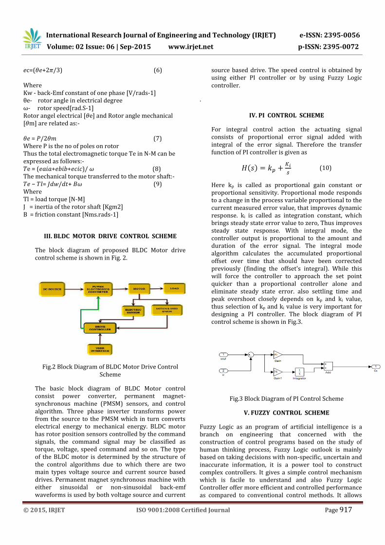
Fig.13 Stator Back Emf for PI Control Scheme
Fig.14 Stator Back Emf for Fuzzy control scheme
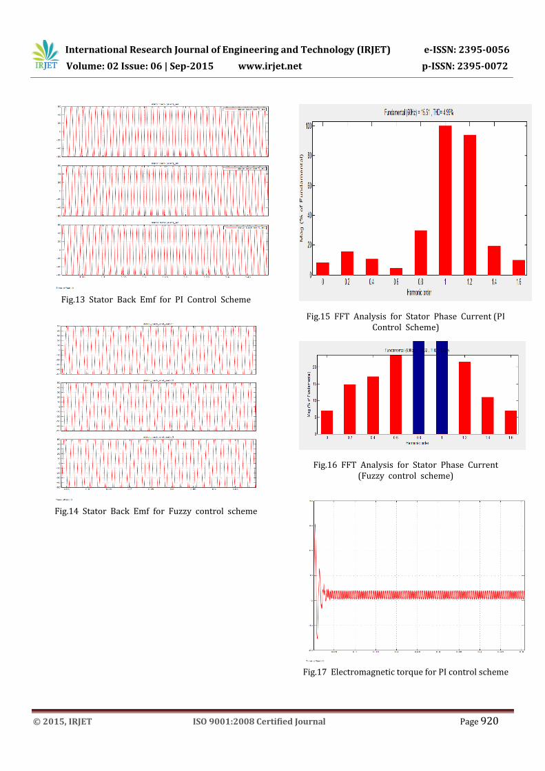
Fig.15 FFT Analysis for Stator Phase Current (PI Control Scheme)
Fig.16 FFT Analysis for Stator Phase Current (Fuzzy control scheme)
Fig.17 Electromagnetic torque for PI control scheme

International Research Journal of Engineering and Technology (IRJET) e-ISSN: 2395-0056
Volume: 02 Issue: 06 | Sep-2015 www.irjet.net p-ISSN: 2395-0072
© 2015, IRJET ISO 9001:2008 Certified Journal Page 921
Fig.18 Electromagnetic Torque for Fuzzy control scheme
VII. CONCLUSION
A detailed Simulink model for a BLDC Motor drive system with stator current control by using Simulink blocks has been developed and operated at rated speed.
Two different control schemes i.e. PI (Proportional Integral) and Fuzzy Logic control schemes have been developed here. Simulation has been carried out from several simulation tools because of its flexibility in working with digital and analog devices. A mathematical model is easily incorporated in the matlab simulation and the presence of numerous tool boxes and support guides simplifies the simulation of large control system. Simulink is capable of showing real time results with reduced simulation time process and debugging.
Usually in such drive system the inverter is driven either by PI or by Fuzzy Logic controller. A comparative study has been made of the PI and Fuzzy Logic control schemes in terms of power quality, speed error and current control ability.
After reviewing the results of the simulation, observations are prepared which shows the essential points in performance comparision. The Simulink simulation allows performance study of BLDC Motor drives with two current control techniques. Table 1 presents the summary obtained from simulated results and it shows use of specific controller for particular application.
Table 1 Performance Analysis
S. No.
Specifications
PI Control Scheme
Fuzzy Control Scheme
1 Current Fluctuation
25 Amp.
22 Amp.
2 Attain Rated Speed at
42 msec.
37 msec.
3 Speed fluctuation
damped out
32 msec.
25 msec.
4 THD 4.99 % 4.58%
This study proves that Fuzzy Logic controllers are better than PI controllers. The simulation with Fuzzy Logic controller allows faster simulations with reduced time and computational resources.
A speed controller has been designed successfully for closed loop operation of the BLDC Motor drive system so that the motor runs at the reference or commanded speed. The modeled simulated system has a fast response with least error thus validating the design method of the speed controller.
REFERENCES
[1] Neethu U., Jisha V. R.,“Speed Control of Brushless DC Motor : A Comparative Study”, IEEE International Conference on Power Electronics, Drives and Energy Systems, Vol. 8, No. 12, 16-19 December 2012, Bengaluru India.
[2] Chee W. Lu,“Torque Controller for Brushless DC Motors”, IEEE Transactions on Industrial Electronics, Vol. 46, No. 2, April 1999.
[3] Tony Mathew, Caroline Ann Sam,”Closed Loop Control of BLDC Motor Using a Fuzzy Logic Controller and Single Current Sensor”, International Conference on Advanced Computing and Communication Systems (ICACCS), Vol. 2, No. 13, 19-21 December 2013, Coimbatore India.
[4] T. Raghu, S. Chandra Sekhar, J. Srinivas Rao,“SEPIC Converter based – Drive for Unipolar BLDC Motor”, International Journal of Electrical and

International Research Journal of Engineering and Technology (IRJET) e-ISSN: 2395-0056
Volume: 02 Issue: 06 | Sep-2015 www.irjet.net p-ISSN: 2395-0072
© 2015, IRJET ISO 9001:2008 Certified Journal Page 922
Computer Engineering (IJECE), Vol.2, No.2, April 2012, pp. 159-165.
[5] M. A. Jabbar, Hla Nu Phyu, Zhejie Liu, Chao Bi,“Modelling and Numerical Simulation of a Brushless Permanent – Magnet DC Motor in Dynamic Conditions by Time – Stepping Technique”, IEEE Transactions on Industry Applications, Vol. 40, no. 3, MAY/JUNE 2004.
[6] A. Halvaei Niasar, Abolfazl Vahedi, Hassan Moghbeli,“Torque Control of Brushless DC Motor Drive based on DSP Technology”, Proceeding of International Conference on Electrical Machines and Systems 2007, Oct. 8~11, Seoul, Korea.
[7] Santanu Kumar Nayak, Pallav Dutta, “A Comparative Study of Speed Control of DC Brushless Motor Using PI and Fuzzy Controller”, IEEE Transactions on Industrial Electronics, Vol. 15, No. 2, 2015.
[8] Md Mustafa Kamal, Lini Mathew,”Speed Control of Brushless DC Motor Using Fuzzy Based Controllers”, IEEE Students’ Conference on Electrical, Electronics and Computer Science, Vol. 14, No. 1, 2014.
[9] Madhusudan Singh, Archana Garg,“Performance Evaluation of BLDC Motor with Conventional PI and Fuzzy Speed Controller”, IEEE Transactions on Industrial Electronics, Vol. 12, No. 9, 2012.
[10] M. Surya Kalavathi, C. Subba Rami Reddy,“Performance Evaluation of Classical and Fuzzy Logic Control Techniques for Brushless DC Motor Drive”, IEEE Transactions on Industrial Electronics, Vol 12, No 7, 2012, pp. 488-491.