performance of yielding seam structural plate pipe...
TRANSCRIPT
36 TRANSPORTATION RESEARCH RECORD 1231
Performance of Yielding Seam Structural Plate Pipe Culvert
EARLE w. MAYBERRY AND MARK A. GOODMAN
During project development for construction of Interstate 94, northeast of Miles City, Montana, several alternatives were evaluated regarding perpetuation of two large drainages under extensive fills. The alternative selected consisted of installing two structural steel plate culverts. These culverts used the yielding seam concept to relieve the load on the structure by providing controlled slippage in the longitudinal lapped seams. The subsequent reduction in pipe circumference would allow the soil to carry a portion of the load, therefore allowing a reduction in plate thickness and material savings as compared to a conventionally designed structure. Use of this product, relatively new to highway construction applications in 1983, was approved as an experimental feature. Experimental status required preparation of an acceptable work plan, including monitoring of fill settlements, fill pressures, pipe diameter changes, and strain gauge measurements. The purpose of this experimental feature was twofold. First, a reduction in plate gauge was intended to reduce pipe material costs, yet still provide a structurally sound installation. Second, it would be beneficial to monitor and obtain measurements of earth pressures generated in highway fills of this nature. The measurements would allow comparison of actual fill pressures generated versus design pressures as computed by standard methods and procedures. Additionally, information regarding settlement of foundations under high fills, pipe strain measurements, and pipe diameter changes could be obtained. Reduction in vertical loads was realized as a result of seam slippage, and the installations have performed as expected and as designed. A discussion of the site and installation, instrumentation procedures and observations, and data obtained and recommendations for future projects of this nature are contained within.
The Montana Department of Highways became involved with th potential use of yield ing seam pipe in 1979. It had become apparent that constructi n of a portion oflntcrs1a1 94, nonbea t of Miles ity, lontana. would pose unusual structural and cost requirements for the culvert installations at two sites due to extremely high roadway fills.
A relatively new culvert product, Key-Hole Slot, which incorporated the feature of yiel ling eams, offered potential plate-gauge and co"t ic du~ti'""n :; over conventionally designed multiplatc pipe and was proposed for use. Bridges w re also con idcrcd, but cost were thought to be excessiv due t fill heights .
The first installation was a 12.5-ft-diameter structural plate pipe located under 78 ft of cover in 1he pring reek drainage at plan cation I ()2- + 05. The Spring reek cul e rt required a plate thicknes of 0.18 -i n. (7-gauge) utilizing tbe yie lding ·cam concept. By comparison a conventionall y designed structure, using design criteria as published by the Federal
Montana Department of Highways, 2701 Prospect Avenue, Helena, Mont. 59620.
Highway Administration (1), would exceed recommended fill height requirements for 0.280-in . (1-gauge) steel.
The second installation was a 15.0-ft-diameter structural plate pipe located under 45 ft of cover in the Deep Creek drainage at plan Station 1201+10. The Deep Creek installation required a plate thickness of 0.138-in. (10-gauge) using the yielding seam concept , while a conventionally designed structure would have required a plate thickness of 0.249-in. (3-gauge) steel.
At both pipe locations , the natural foundation materials consisted of loose silt overlying sandstone stringers and shale. The loose silt and sandstone stringers were removed to a depth of 5 ft and a width equal to three pipe diameters. The area was then backfilled with A-2-4 material to provide a foundation of uniform quality and density. Backfill for both pipes consisted mainly of sandy silt to silty, sandy gravel derived from local Yellowstone River terrace deposits.
The water table at Deep Creek was 3 ft below the ground line; however, at Spring Creek, the water table was at the surface. Fabric-wrapped cut-off drains were installed west of this pipe to provide free drainage within the pipe foundation.
Backfill procedures for Key-Hole Slot pipe are the same as for any structural plate installation. Proper foundation preparation and backfilling procedures must be followed.
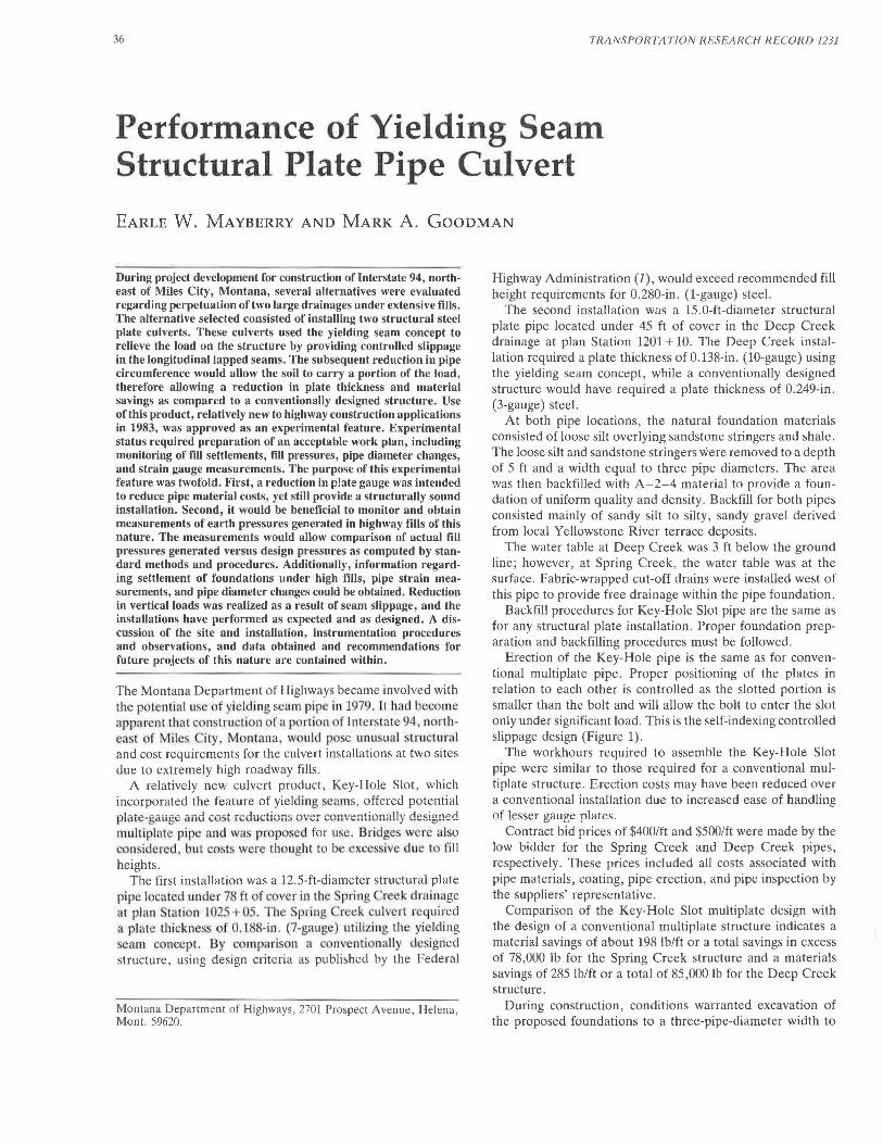
Erection of the Key-Hole pipe is the same as for conventional multiplate pipe. Proper positioning of the plates in relation to each other is controlled as the slotted portion is smaller than the bolt and will allow the bolt to enter the slot only under significant load. This is the self-indexing controlled slippage design (Figure 1) .
The workhours required to assemble the Key-Hole Slot pipe were similar to those required for a conventional multiplate structure. Erection costs may have been reduced over a conventional installation due to increased ease of handling of lesser gauge plates.
Contract bid prices of $400/ft and $500/ft were made by the low bidder for the Spring Creek and Deep Creek pipes, respectively. These prices included all costs associated with pipe materials, coating, pipe erection, and pipe inspection by the suppliers' representative.
Comparison of the Key-Hole Slot multiplate design with the design of a conventional multiplate structure indicates a material savings of about 198 lb/ft or a total savings in excess of 78,000 lb for the Spring Creek structure and a materials savings of 285 lb/ft or a total of 85,000 lb for the Deep Creek structure.
During construction, conditions warranted excavation of the proposed foundations to a three-pipe-diameter width to
Mayberry and Goodman
- - - - - ----- ----- ~ - -- - -- -- - -~ - ---
' '
'./,6' RAlJ
I
A.-J
OVERLAPPED PLATES FIGURE 1 Keyhole-Hole slot detail.
insure uniformity of any settlement surrounding the pipes. This increased total excavation costs by approximately $30,000.
INSTRUMENTATION PROCEDURES AND OBSERVATIONS
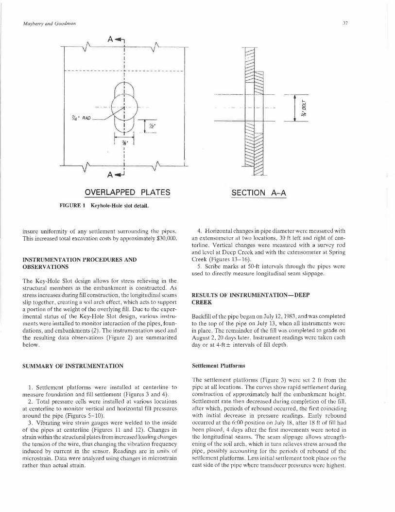
The Key-Hole Slot design allows for stress relieving in the structural members as the embankment is constructed. As stress increases during fill construction, the longitudinal seams slip together, creating a soil arch effect, which acts to support a portion of the weight of the overlying fill. Due to the experimental status of the Key-Hole Slot design, various instruments were installed to monitor interaction of the pipes, foundations, and embankments (2). The instrumentation used and the resulting data observations (Figure 2) are summarized below.
SUMMARY OF INSTRUMENTATION
1. Settlement platforms were installed at centerline to measure foundation and fill settlement (Figures 3 and 4).
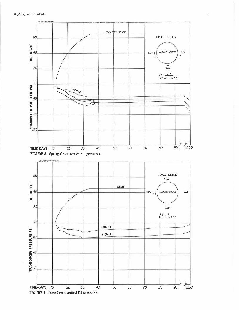
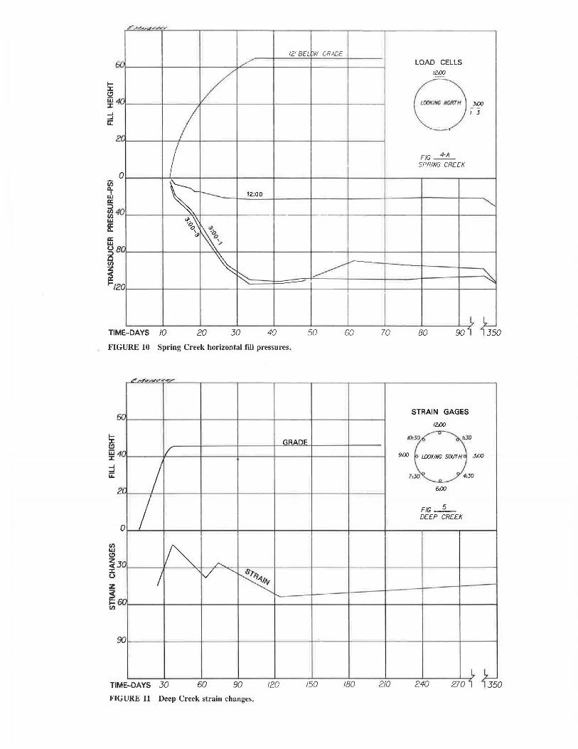
2. Total pressure cells were installed at various locations at centerline to monitor vertical and horizontal fill pressures around the pipe (Figures 5-10).
3. Vibrating wire strain gauges were welded to the inside of the pipes at centerline (Figures 11 and 12). Changes in strain within the structural plates from increased loading changes the tension of the wire, thus changing the vibration frequency induced by current in the sensor. Readings are in units of microstrain. Data were analyzed using changes in microstrain rather than actual strain.
37
SECTION A-A
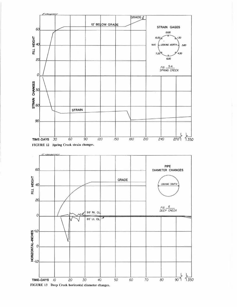
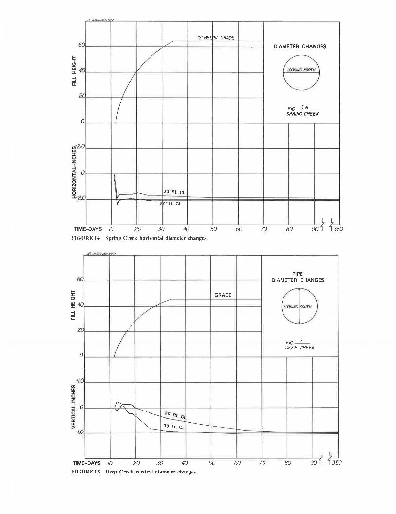
4. Horizontal changes in pipe diameter were measured with an extensometer at two locations, 30 ft left and right of centerline. Vertical changes were measured with a survey rod and level at Deep Creek and with the extensometer at Spring Creek (Figures 13-16).
5. Scribe marks at 50-ft intervals through the pipes were used to directly measure longitudinal seam slippage.
RESULTS OF INSTRUMENTATION-DEEP CREEK
Backfill of the pipe began on July 12, 1983, and was completed to the top of the pipe on July 13, when all instruments were in place. The remainder of the fill was completed to grade on August 2, 20 days later. Instrument readings were taken each day or at 4-ft ± intervals of fill depth .
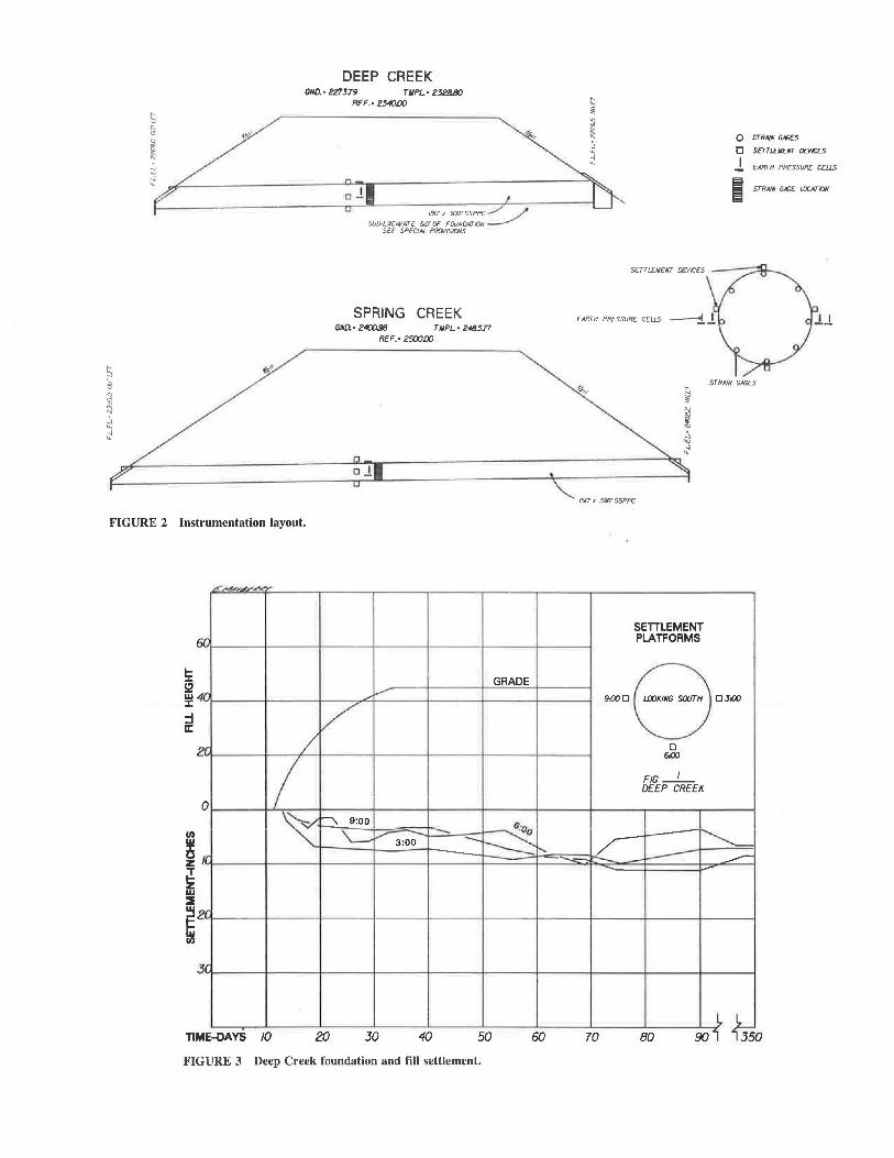
Settlement Platforms
The settlement platforms (Figure 3) were set 2 ft from the pipe at all locations. The curves show rapid settlement during construction of approximately half the embankment height. Settlement rate then decreased during completion of the fill, after which, periods of rebound occurred, the first coinciding with initial decrease in pressure readings. Early rebound occurred at the 6:00 position on July 18, after 18 ft of fill had been placed, 4 days after the first movements were noted in the longitudinal seams. The seam slippage allows strengthening of the soil arch, which in turn relieves stress around the pipe, possibly accounting for the periods of rebound of the settlement platforms. Less initial settlement took place on the east side of the pipe where transducer pressures were highest.
I''
DEEP CREEK GND.• 227379 TllPL· 2J2/J.IJO
REF.• 2340lXJ
180' x JOO' SSPPC _./' ~ SUB-EXCPVATE 5UOF FOUNDATION ___...,.
SEE SPECIAL PROllSIONS
SPRING CREEK GND. • 2400.98 T llPL. • 248377
REF.• 2500lXJ
oJ
FIGURE 2 Instrumentation layout.
!c !2 w ::c :I u:::
Cl) w
~ ;! z w
I
Tl
L!:',,.,,,,_.,,~,e,.
er
411 ·
zr,
0
f(
2r
3'
ME-OAYS 10
GRADE ,,..,-
/ /
I \v ~ 9:00
- fl:oo ---'-----v 3:00 ---~~ --
20 30 40 50 60
FIGURE 3 Deep Creek foundation and fill settlement.
0 STRNN G-'GES
0 SETTL£11E/ff DEVICES
l EARTH PRESSURE CEUS
' I STRNN G-'GE LOCIV/ON
EARTH PRESSLJRE CEUS
STRNN G-'GES
15[/ A 396' SSPPC
SETILEMENT PLATFORMS
~DeD~ D
61)()
FIG-1-
DEEP CREEK
~ ~ _,...--
70 BO 90 1~ ~ 50

i
ffi :::c u z ~ w ~
£. ..J..4#~-.1 .... ~,.e.<Y'
6 r,
r.
'( 2
0
r(
'( ~2 (/)
'( 3
I I ~
12' BEL DW GRADE
/
v 3:oo
1~"0--- . ..........,
s:on - :---...... .......... -
TIM E-DAYS 10 20 30 40 50 60
FIGURE 4 Spring Creek foundation and fill settlement.
6 0
'O
•r. 2
0
ii5
~ 0 !52
(/) (/) w a: II..
0
~ ',r71'i"~.<'
/
I \'--
-~ ""-
\:
·- -
,,,i.---
v
3:00-1 9:00-1 --~ --------...,. 3:00 3
..!_:00,3
GRADE
6:00
ffi4 u ::::> c (/) ""- i-----~ z ~6 0 t-
TIM E-OAYS 10 20 30 40 50
FIGURE 5 Deep Creek horizontal fill pressures.
60
SETILEMENT PLATFORMS
9iXJO LOOKING NOffTH OJ.00
0 6:00
FIG_!±_ SPRING CREEK
~ "-
70 80 90 i~ fJs 0
LOAD CELLS
9iXJ J 1 LOOKING SOIJT H 1 J J.00
-6:00
FIG-2-DEEP CREEK
--~ J-
-:_;
70 80 90j~ ~ 50
/.....,.-1.,..l"L.---
12' BEL p.v GR/llJE
;n 6
4n
2r
0 ii> ~ a:
m40 w a: ll..
a: w u :J 0 en z
EJfl
~I 20
TIM E-OAYS 10
_,,/---
/ I I ~~ \~
........... 9:00-1
............ .......... 9:00-3
20 30 40
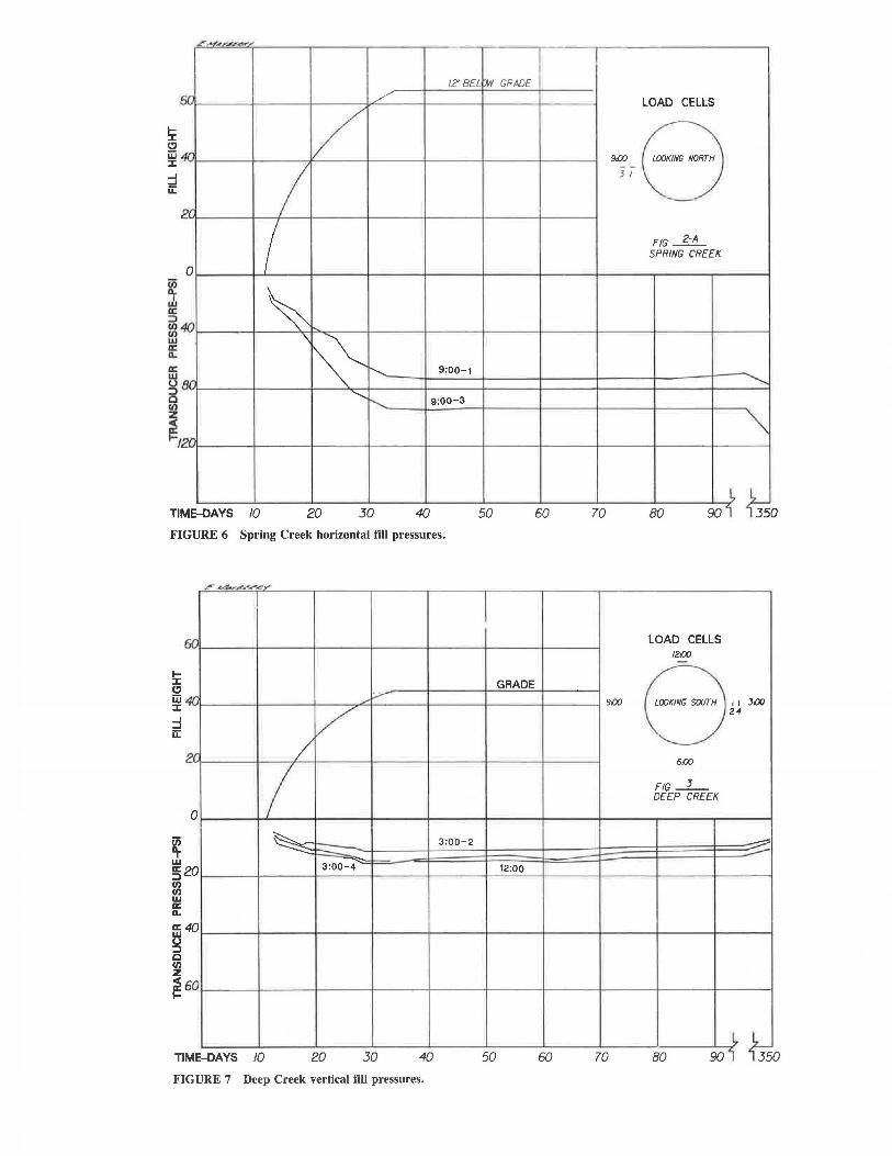
FIGURE 6 Spring Creek horizontal fill pressures.
~ A. ,,_4.,,,,.,._,,,,,,,..~.,,,,.
60
.di'".
2r
0
~ a: :J (/) (/) w a: ll..
20
a: g 40
c ~ ~ 60
Tl ME-OAYS
/ /
I ~
------ -3:00 4
10 20
/;,..-
30 40
FIGURE 7 Deep Creek vertical fill pressures.
3:00-2
50
I
GRADE
12:00
50
LOAD CELLS
9:00 WOKING NORTH - -JI
FIG~ SPRING CREEK
-............
~
60 70 80 90jl ~ 0
LOAD CELLS 12:00 -
9:00 LOOKINfJ S()(fT H I I J,()Q 24
6:00
FIG-3-DEEP CREEK
_......, :::--
60 70 80 90'1L ~ 0
Mayberry and Goodman
'A'l'.b'. ~A' -~·- --- --- --- -
!i: (!) jjj ::c ::I u::
5r:
IJf'.
2r
0
40
ar.
20
TIME-DAYS /0
I/ v
I I ~ 9·o ~ ~" -~
•-v-2
s:oo
20 30 40
FIGURE 8 Spring Creek vertical fill pressures .
.J."f".~_..,.....,.""-... ~ .. ~.i""
!i: (!) jjj ::c ::I u::
60
40
2r.
0
0
40
60
TIM E-OAVS 10
-.,,.-
/ /
I ~ ~
-----
20 30 40 FIGURE 9 Deep Creek vertical fill pressures.
12.' BEL rM' GRADE
- ----::iO
GRADE
9:00-2
9:00 4
50
41
LOAD CELLS
9,00 I LOOKING NORTH I J..oo I 2 2
-6:00
FJG--2L SPRING CREEK
" ~
60 70 80 90 i~ {Ts 0
LOAD CELLS /2{X)
="8 J:OO 4 2
6{X)
FIG - 4-DEEP CREEK
__..,..,
___.,.
60 70 80 90 i~ {Ts 0
~ (!) iii ::c ...J ...J u:::
if iL a: :::> Cl.I Cl.I w f a: w (.)
5 Cl.I z
,..,.,,,..,,,.._..,,,...,.,,,e,,
i::.1·
dr
2.1".
0
40
ar:
~I 20
Tl ME-DAYS 10
12'Ba tM' GRADE /.-'
/ I I
~ r--... 12:00
<?;,~
~ o'.;
',.
" ~ ~
20 30 40 50 60
FIGURE 10 Spring Creek horizontal fill pressures.
Cl.I w
~ 5 z
~ Cl.I
50
4[1
2r
0
30
60
90
,,,...;,,,,,,,,..e'<<.,,,....
r.R.11.ni:
f
I I ~ /'....
I 'V ""'- .s.,.,
~ ....
LOAD CELLS /2.{)(] -
8-~ I J
FIG~ SPRING CREEK
""
~ ~
70 80 90i~ ~ 0
STRAIN GAGES
/2.{)(]
/(),JI) /:JO
9.-00 l.IXJKING SOIJT"H J{)(J
1(JO 4:30
6.-00
FIG-5-DEEP CREEK
270i ~ ME-OAYS 30 60 90 120 150 180 210 240 TI 0
FIGURE 11 Deep Creek strain changes.
ff,,..,,,,.,.,,,,r,;e.--
12' BE OW GAAi ~E _,/ /
r:;r. ~
"" I 2r I 0 I
30 \ 6G \
\.. 1-.. STRAIN
\
(/)
i u z
~
90
TIM E-DAYS 30 60 90 120 150 180 210
FIGURE 12 Spring Creek strain changes.
~ :c (!) w :c :::l u:::
6f1
4fl
2r
0
(/) . w 1.0
0 z
~ !z § IC 0 :c .
0
/[)
~ ~~~ -"';,.-,.. ,_
,,,i.......-
v /
I~ ~ 30' Rt . CL
\ f.J'\j 30 ' Lt . CL
\
GRADE
,,,.
STRAIN GAGES
12.00
JO..JO 1:30
-9.00 /.001(/NG //OffrH 3:00
MO 4:JO
6.<XJ
FIG~ SPRING CREEK
240 2701~ ~ 0
PIPE DIAMETER CHANGES
8 F/G_6_
DEEP CREEK
~
90jl ~ ME-DAYS 10 20 JO 40 50 60 70 80 Tl 0 FIGURE 13 Deep Creek horizontal diameter changes.
5r.
40
2/.
0
.0 (/)·2 w :c u z "T
~ 0
§ IC 0 :c.z .0
~
Tl ME-DAYS
~,,
'
10
12' BEL M' GRADE
/ v I
v--: 30' Rt. CL.
y l O' Lt. Cl.
20 30 40 50 60
FIGURE 14 Spring Creek horizontal diameter changes.
...-; w4",..._..,~~-""
r: 6
GRADE
·r. ,,, ......--
/ •r. 2 /
0 I .o
0 /~ v \...__
~ ao· ~ r---30' Lt. CL r---......
0
TIM E-DAYS 10 20 30 40 50 60 FIGURE 15 Deep Creek vertical diameter changes.
DIAMETER CHANGES
8 FIG~
SPRING CREEK
70 80 90IL fu 0
PIPE DIAMETER CHANGES
EB FIG-7-DEEP CREEK
70 80 90{ ~ 0
Mayberry and Goodman 45
~~,,.~~~.,
12' BEL iJW GRADE
6n ./
4(] v 2r, I 0
.0 /\
JV \ CL.
0 J --.0
TIM E-DAYS 10 20 30 40
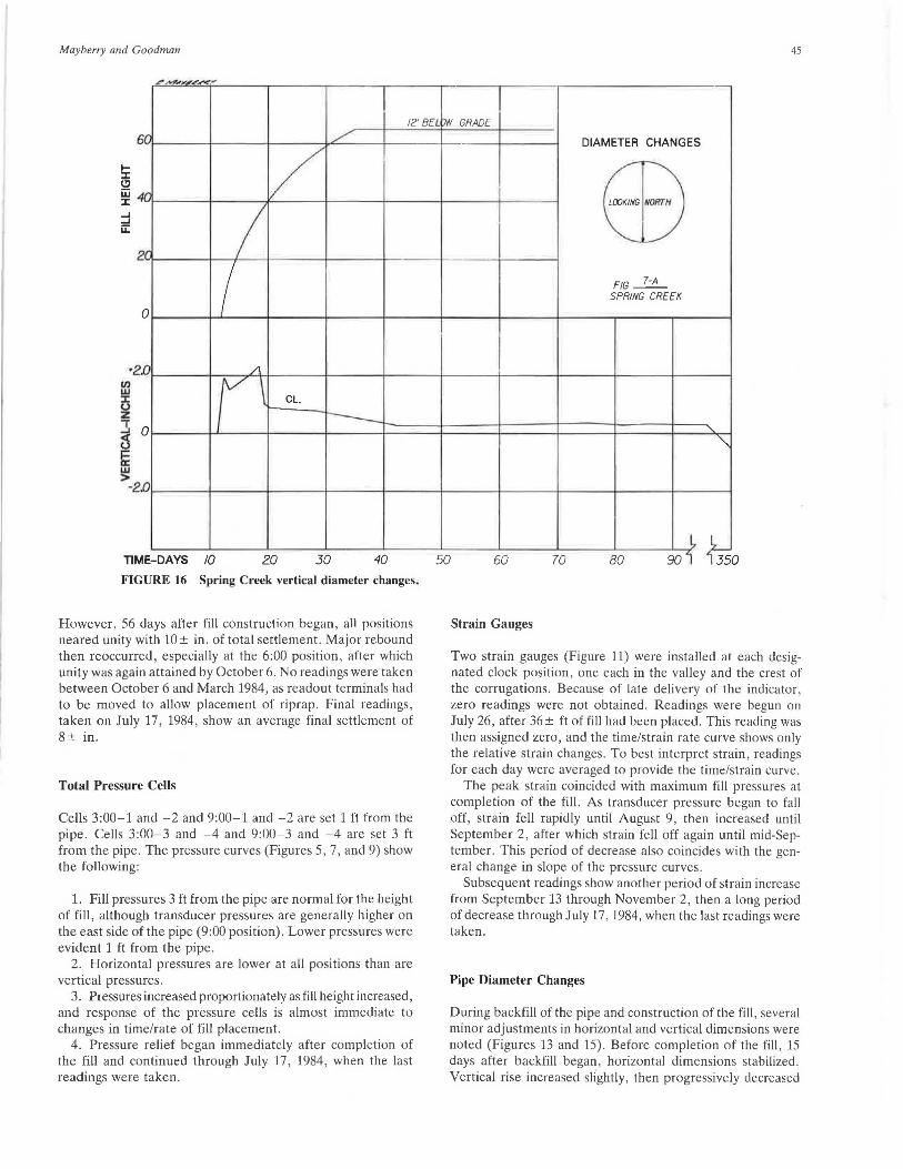
FIGURE 16 Spring Creek verlical diameler changes.
However, 56 days after fill construction began, all positions neared unity with 10 ± in. of total settlement. Major rebound then reoccurred, especially at the 6:00 position, after which unity was again attained by October 6. No readings were taken between October 6 and March 1984, as readout terminals had to be moved to allow placement of riprap . Final readings , taken on July 17, 1984, show an average final settlement of 8± in.
Total Pressure Cells
Cells 3:00-1 and -2 and 9:00-1 and -2 are set 1 ft from the pipe. Cells 3:00-3 and -4 and 9:00-3 and -4 are set 3 ft from the pipe. The pressure curves (Figures 5, 7, and 9) show the following :
1. Fill pressures 3 ft from the pipe are normal for the height of fill, although transducer pressures are generally higher on the east side of the pipe (9:00 position). Lower pressures were evident 1 ft from the pipe.
2. Horizontal pressures are lower at all positions than are vertical pressures.
3. Pressures increased proportionately as fill height increased, and response of the pressure cells is almost immediate to changes in time/rate of fill placement.
4. Pressure relief began immediately after completion of the fill and continued through July 17, 1984, when the last readings were taken.
DIAMETER CHANGES
E8 FIG~
SPRING CREEK
'
""
~ 50 60 70 BO 90 i 35 0
Strain Gauges
Two strain gauges (Figure 11) were installed at each designated clock position, one each in the valley and the crest of the corrugations. Because of late delivery of the indicator, zero readings were not obtained. Readings were begun on July 26, after 36 ± ft of fill had been placed. This reading was then assigned zero, and the time/strain rate curve shows only the relative strain changes. To best interpret strain, readings for each day were averaged to provide the time/strain curve .
The peak strain coincided with maximum fill pressures at completion of the fill. As transducer pressure began to fall off, strain fell rapidly until August 9, then increased until September 2, after which strain fell off again until mid-September. This period of decrease also coincides with the general change in slope of the pressure curves.
Subsequent readings show another period of strain increase from September 13 through November 2, then a long period of decrease through July 17, 1984, when the last readings were taken.
Pipe Diameter Changes
During backfill of the pipe and construction of the fill, several minor adjustments in horizontal and vertical dimensions were noted (Figures 13 and 15) . Before completion of the fill, 15 days after backfill began, horizontal dimensions stabilized. Vertical rise increased slightly, then progressively decreased

46
due to seam slippage, starting 7 days after fill operations began or at 21 ft of fill over the pipe (20 ± psi) .
RESULTS OF INSTRUMENTATION-SPRING CREEK
Backfill of this pipe began on September 9, 1983, and was completed to the top of the pipe on September 13. The fill was then constructed to a height of 63 ft by October 5, 22 days later. Approximately 12 ft of fill remained to reach grade. Instrument readings were taken each day or at 5 ft± intervals of fill depth.
Because of failure of several strain gauges placed in the valleys of the pipe corrugations at Deep Creek, only one gauge was placed at each clock position between the valleys and crests at Spring Creek. In addition, the vertical pressure cells at 3:00-4 and 9:00-4 were eliminated because they were not believed to be essential in the fill pressure analysis. The remaining instruments were placed exactly as at Deep Creek.
Settlement Platforms
Initial settlement rate continued high until the fill height reached 55 ft, when the rate decreased (Figure 4); whereas at Deep Creek settlement, the rate decreased after approximately 20 ft of fill were placed. The last readings on July 17, 1984, show an average settlement of 12 ± in.
Total Pressure Cells
Pressure relationships around the pipe are generally similar to those at Deep Creek except that pressure curves are abnormally high at 3:00-1 and -3 and 9:00-1 and -1 (Figures 6, 8, and 10). In addition, at the 3:00 position, where pressures were highest, the 1 and 3 cells show nearly identical readings, which is not the case at Deep Creek. The high fill pressures at the sides of the pipe could be caused by excessive compaction of the backfill and/or the rate of fill construction. At Deep Creek, 45 ft of fill were placed over a 20-day period. At Spring Creek, 63 ft of fill were placed over a 22-day period, or nearly one-third more fill was placed in the same time span. Little pressure relief took place around the pipe between October 1983 and February 1984 when fill construction began once again. Pressures then increased around the pipe and remained high through July 17 , 19114, when final readings were taken.
Strain Gauges
The time/strain curve is nearly proportional to the time/fill height curve (Figure 12). However, strain remained constant through February 1984, with only a minor decrease. Strain increased during completion of the fill in 1984, after which some decrease occurred through July 1984.
Pipe Diameter Changes
Unlike the pipe at Deep Creek, which, after initial adjustments, returned to the original horizontal diameter 15 days
rnANSPORTA TION RESEARCH RECORD 1231
after backfill began, the Spring Creek pipe (Figures 14 and 16) remains about 2 in. less than the original horizontal diameter. Vertical rise first increased then decreased exactly as the Deep Creek pipe did, after 23 ft of fill were in place over the pipe. However , the rise increase was more than 2 in. as compared with .25 in. at Deep Creek.
Photos of the various stages of construction are included in Figures 17-24.
CONCLUSIONS
Comparison of the data obtained from the instrumentation and seam slippage survey at Deep Creek indicates the soil arch began to form after the embankment reached a height of 10 to 15 ft over the pipe. The period of strain change , change in slope of pressure, and settlement rebound suggest the soil arch forms by a series of dynamic adjustments through construction until about 40 days after fill completion. Thereafter , long-term adjustment takes place over a period of several months.
FIGURE 17 Pipe assembly on preshaped bed at Deep Creek.
FIGURE 18 Backfill operation at Deep Creek.
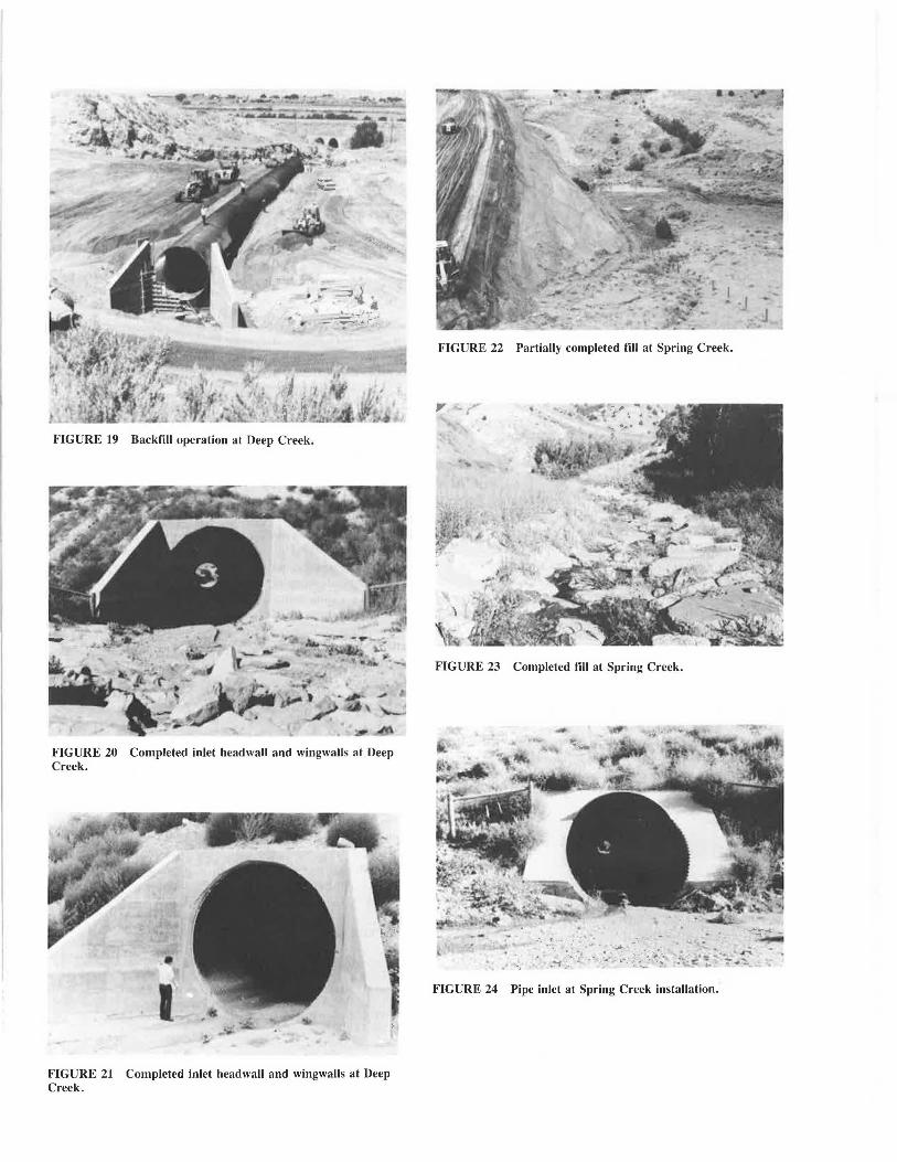
FIGURE 19 Backfill operation at Deep Creek.
FIGURE 20 Completed inlet headwall and wingwalls at Deep Creek.
FIGURE 21 Completed inlet headwall and wingwalls at Deep Creek.
FIGURE 22 Partially completed fill at Spring Creek.
FIGURE 23 Completed fill at Spring Creek.
FIGURE 24 Pipe inlet at Spring Creek installation.
48 TRANS PO RTATION RESEARCH R ECORD 123 1
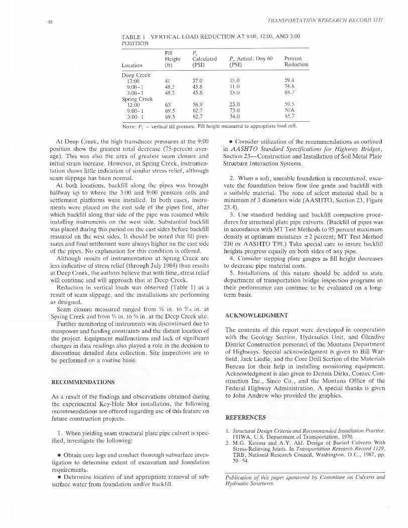
TABLE 1 VERTICAL LOAD REDUCTION AT 9:00, 12:00, AND 3:00 POSITION
Fill P,. Height Calculated P, Actual, Day 60 Percent
Location (ft) (PSI) (PSI) Reduction
Deep Creek 59.4 12:00 41 37.0 15.0
9:00-1 48.5 43 .8 11.0 74.8 3:00-1 48.5 43.8 15.U 6':J .7
Spring Creek 12:00 63 56.9 23.0 59 .5 9:00-1 69.5 62.7 73.0 NIA 3:00-1 69.5 62.7 34.0 45.7
NoTE: P, = vertical fill pressure. Fill height measured to appropriate load cell.
At Deep Creek, the high transducer pressures at the 9:00 position show the greatest total decrease (75-percent average). This was also the area of greatest seam closure and initial strain increase. However, at Spring Creek, instrumentation shows little indication of similar stress relief, although seam slippage has been normal.
At both locations, backfill along the pipes was brought halfway up to where the 3:00 and 9:00 pressure cells and settlen1ent platforms were installed . In both cases , instruments were placed on the east side of the pipes first, after which backfill along that side of the pipe was resumed while installing instruments on the west side. Substantial backfill was placed during this period on the east sides before backfill resumed on the west sides. It should be noted that fill pressures and final settlement were always higher on the east side of the pipes. No explanation for this condition is offered.
Although results of instrumentation at Spring Creek are less indicative of stress relief (through July 1984) than results at Deep Creek, the authors believe that with time, stress relief will continue and will approach that at Deep Creek.
Reduction in vertical loads was observed (Table 1) as a result of seam slippage, and the installations are performing as designed.
Seam closure measured ranged from Ys in. to 911 6 in. at
Spring Creek and from Y4 in. to 3ls in. at the Deep Creek site. Further monitoring of instruments was discontinued due to
manpower and funding constraints and the distant location of the project. Equipment malfunctions and lack of significant changes in data readings also played a role in the decision to discontinue detailed data collection. Site inspections are to be performed on a routine basis .
RECOMMENDATIONS
As a result of the findings and observations obtained during the experimental Key-Hole Slot installation, the following recommendations are offered regarding use of this feature on future construction projects.
l. When yielding seam structural plate pipe culvert is specified , investigate the following:
• Obtain core logs and conduct thorough subsurface investigation to determine extent of excavation and foundation requirements.
• Determine location of and appropriate removal of subsurface water from foundation and/or backfill.
• Consider utilization of the recommendations as outlined in AASHTO Standard Specifications for Highway Bridges, Section 23-Construction and Installation of Soil Metal Plate Structure Interaction Systems.
2. When a soft, unstable foundation is encountered, excavate the foundation below flow line grade and backfill with a suitable material. The zone of select material shall be a minimum of 3 diameters wide (AASHTO, Section 23, Figure 23.4).
3. Use standard bedding and backfill compaction procedures for structural pl ate pipe culverts. (Backfill of pipes was in accordance with MT Test Methods to 95 percent maximum density at optimum moistures ± 2 percent; MT Test Method 210 or AASHTO T99.) Take special care to insure backfill heights progress equally on both sides of any pipe.
4. Consider stepping plate gauges as fill height decreases to decrease pipe material costs.
5. Installations of this nature should be added to state department of transportation bridge inspection programs so their performance can continue to be evaluated on a longterm basis.
ACKNOWLEDGMENT
The contents of this report were developed in cooperation with the Geology Section , Hydraulics Unit, and Glendive District Construction personnel of the Montana Department of Highways. Special acknowledgment is given to Bill Warfield, Jack Liedle, and the Core Drill Section of the Materials Bureau for their help in installing monitoring equipment. Acknowledgment is also given to Dennis Dirks, Contee Construction Inc., Sinco Co., and the Montana Office of the Federal Highway Administration. A special thanks is given to John Andrew who provided the graphics.
REFERENCES
1. Structural Design Criteria and Recommended Installation Practice. FHWA, U.S. Department of Transportation, 1970.
2. M.G. Katona and A.Y. Aki. Design of Buried Culverts With Stress-Relieving Joints. In Transportation Research Record 1129, TRB, National Research Council, Washington , D.C., 1987, pp . 39-.'i4
Publication of this paper sponsored by Committee on Culverts and Hydraulic Structures.