performance specification test program setsperformance specification test program sets comments,...
TRANSCRIPT

AMSC N/A AREA ATTS
MIL-PRF-32070A 10 January 2012 SUPERSEDING MIL-PRF-32070 30 January 2002
PERFORMANCE SPECIFICATION
TEST PROGRAM SETS
Comments, suggestions, or questions on this document should be addressed to the NavalAir Systems Command (Commander, Naval Air Warfare Center Aircraft Division, Code 4L8000B120-3, Highway 547, Lakehurst, NJ 08733-5100) or emailed to [email protected]. Since contact information can change, you may want to verify the currency of this address information using the ASSIST online database at https://assist.daps.dla.mil.
INCH-POUND
MIL-PRF-32070A
ii
CONTENTS
1. SCOPE ................................................................................................................................. 1 1.1 Scope ....................................................................................................................... 1 2. APPLICABLE DOCUMENTS ............................................................................................... 1 2.1 General .................................................................................................................... 1 2.2 Government documents .......................................................................................... 1 2.2.1 Standards and Handbooks ....................................................................................... 1 2.2.2 Other Government documents, drawings and publications .................................... 1 2.3 Non-Government publications ................................................................................ 2 2.4 Order of precedence ................................................................................................ 2 3. REQUIREMENTS .................................................................................................................. 3 3.1 First article inspection ............................................................................................. 3 3.2 General performance requirements ......................................................................... 3 3.2.1 Environment ............................................................................................................ 3 3.2.2 Fault isolation (FI) .................................................................................................. 3 3.2.2.1 Test Program Hardware (TPH) fault isolation ........................................................ 3 3.2.2.2 Weapons Replaceable Assembly/Line Replaceable Unit
(WRA/LRU fault isolation ...................................................................................... 3 3.2.2.3 Shop Replaceable Assembly/Shop Replaceable Unit (SRA/SRU)
fault isolation .......................................................................................................... 3 3.2.3 TPS hook-up time ................................................................................................... 4 3.2.4 Operational footprint ............................................................................................... 4 3.2.5 Operating personnel ................................................................................................ 4 3.2.6 Technical architecture interface requirements ........................................................ 4 3.2.7 Test Accuracy Ratio (TAR) .................................................................................... 4 3.2.8 TPS transportability ................................................................................................ 4 3.2.9 Unit Under Test (UUT) and Automated Test Equipment (ATE) integrity ............. 4 3.3 Software requirements ............................................................................................ 5 3.3.1 Test Program (TP) format ....................................................................................... 5 3.3.2 Naming convention ................................................................................................. 5 3.3.3 Procedures ............................................................................................................... 5 3.3.4 Comments ............................................................................................................... 5 3.3.4.1 Major comments ..................................................................................................... 5 3.3.4.2 Minor comments ..................................................................................................... 5 3.3.4.3 Functional comments .............................................................................................. 6 3.3.4.4 Program flow comments ......................................................................................... 6 3.3.4.5 Test program header comments .............................................................................. 6 3.3.4.5.1 TP title block ........................................................................................................... 6 3.3.4.5.2 UUT configuration data .......................................................................................... 6 3.3.4.5.3 TP configuration data .............................................................................................. 6 3.3.4.5.4 Distribution Statement ............................................................................................ 6 3.3.5 UUT confirmation section ...................................................................................... 6

MIL-PRF-32070A
iii
CONTENTS 3.3.6 Testing sequence ..................................................................................................... 7 3.3.6.1 TPS resource items ................................................................................................. 7 3.3.6.2 ATE survey tests ..................................................................................................... 7 3.3.6.3 TPH pre-performance testing .................................................................................. 7 3.3.6.4 TPH performance test ............................................................................................. 7 3.3.6.5 TPH diagnostic test ................................................................................................. 8 3.3.6.6 TP termination ........................................................................................................ 8 3.3.7 UUT testing ............................................................................................................. 8 3.3.7.1 UUT pre-performance tests ..................................................................................... 8 3.3.7.2 UUT performance test............................................................................................. 9 3.3.7.3 UUT diagnostic (see 6.3.4) ................................................................................... 10 3.3.7.4 TP termination ...................................................................................................... 10 3.3.8 Standard messages ................................................................................................ 10 3.3.9 Main menu options ............................................................................................... 10 3.3.10 Test results ............................................................................................................ 11 3.3.11 Graphics ................................................................................................................ 11 3.4 Hardware requirements ......................................................................................... 11 3.4.1 Nomenclature ........................................................................................................ 11 3.4.2 Accessory set ........................................................................................................ 11 3.4.3 Ancillary equipment .............................................................................................. 11 3.4.4 Cable assemblies (see 6.4.4) ................................................................................. 11 3.4.4.1 Cable design .......................................................................................................... 11 3.4.4.2 Cable assembly branching limit ............................................................................ 12 3.4.5 Holding fixture (HF) ............................................................................................. 12 3.4.6 Interface Device (ID) (see 6.4.14) ........................................................................ 12 3.4.7 Test fixture (TF) (see 6.4.19) ................................................................................ 13 3.4.8 Item Unique Identification (IUID) marking of US military property ................... 14 3.4.9 Product marking .................................................................................................... 14 3.4.10 Maintainability ...................................................................................................... 14 3.4.11 Reliability .............................................................................................................. 14 3.4.11.1 Mean-time-between-failure (MTBF) .................................................................... 14 3.4.11.2 Connector durability ............................................................................................. 14 3.4.12 Safety .................................................................................................................... 14 3.4.13 Workmanship ........................................................................................................ 15 3.4.13.1 Soldering ............................................................................................................... 15 3.4.13.2 Cleaning ................................................................................................................ 15 3.4.13.3 Threaded parts or devices ..................................................................................... 15 3.4.13.4 Wiring ................................................................................................................... 15 3.4.13.5 Shielding ............................................................................................................... 15 3.4.14 Construction .......................................................................................................... 16 4. VERIFICATION ................................................................................................................... 16 4.1 Classification of inspections ................................................................................. 16 4.2 Requirements ........................................................................................................ 16 4.2.1 First article inspection ........................................................................................... 16
MIL-PRF-32070A
iv
CONTENTS 4.2.2 General performance characteristics ..................................................................... 16 4.2.2.1 Environment .......................................................................................................... 16 4.2.2.2 Fault isolation........................................................................................................ 16 4.2.2.2.1 TPH fault isolation ................................................................................................ 16 4.2.2.2.2 WRA/LRU fault isolation ..................................................................................... 16 4.2.2.2.3 SRA/SRU fault isolation ....................................................................................... 16 4.2.2.3 TPS hook-up time ................................................................................................. 16 4.2.2.4 Operational footprint ............................................................................................. 17 4.2.2.5 Usability of TPD for operating personnel ............................................................. 17 4.2.2.6 Technical architecture interface requirements ...................................................... 17 4.2.2.7 Test Accuracy Ratio (TAR) .................................................................................. 17 4.2.2.8 TPS transportability .............................................................................................. 17 4.2.2.9 UUT and ATE integrity ........................................................................................ 17 4.2.3 Software requirements .......................................................................................... 17 4.2.3.1 TP format .............................................................................................................. 17 4.2.3.2 Naming convention ............................................................................................... 17 4.2.3.3 Procedures ............................................................................................................. 17 4.2.3.4 Comments ............................................................................................................. 17 4.2.3.4.1 Major comments ................................................................................................... 17 4.2.3.4.2 Minor comments ................................................................................................... 17 4.2.3.4.3 Functional comments ............................................................................................ 18 4.2.3.4.4 Program flow comments ....................................................................................... 18 4.2.3.4.5 Test program header comments ............................................................................ 18 4.2.3.4.5.1 TP title block ......................................................................................................... 18 4.2.3.4.5.2 UUT configuration data ........................................................................................ 18 4.2.3.4.5.3 TP configuration data ............................................................................................ 18 4.2.3.4.5.4 Distribution Statement .......................................................................................... 18 4.2.3.5 UUT confirmation section .................................................................................... 18 4.2.3.6 Testing sequence ................................................................................................... 18 4.2.3.6.1 TPS resource items ............................................................................................... 18 4.2.3.6.2 ATE survey tests ................................................................................................... 18 4.2.3.6.3 TPH pre-performance tests ................................................................................... 18 4.2.3.6.4 TPH performance tests .......................................................................................... 18 4.2.3.6.5 TPH diagnostic test ............................................................................................... 18 4.2.3.6.6 TP termination ...................................................................................................... 19 4.2.3.7 UUT testing ........................................................................................................... 19 4.2.3.7.1 UUT pre-performance tests ................................................................................... 19 4.2.3.7.2 UUT performance tests ......................................................................................... 19 4.2.3.7.3 UUT diagnostics ................................................................................................... 19 4.2.3.7.4 TP termination ...................................................................................................... 19 4.2.3.8 Standard messages ................................................................................................ 19 4.2.3.9 Main menu options ............................................................................................... 19 4.2.3.10 Test results ............................................................................................................ 19 4.2.3.11 Graphics ................................................................................................................ 19 4.2.4 Hardware requirements ......................................................................................... 19
MIL-PRF-32070A
v
CONTENTS 4.2.4.1 Nomenclature ........................................................................................................ 19 4.2.4.2 Accessory set ........................................................................................................ 19 4.2.4.3 Ancillary equipment .............................................................................................. 19 4.2.4.4 Cable assemblies ................................................................................................... 19 4.2.4.4.1 Cable design .......................................................................................................... 19 4.2.4.4.2 Cable assembly branching limit ............................................................................ 19 4.2.4.5 Holding fixture (HF) ............................................................................................. 20 4.2.4.6 Interface device (ID) ............................................................................................. 20 4.2.4.7 Test fixture (TF) .................................................................................................... 20 4.2.4.8 IUID marking of US military property ................................................................. 20 4.2.4.9 Product marking .................................................................................................... 20 4.2.4.10 Maintainability ...................................................................................................... 20 4.2.4.11 Reliability .............................................................................................................. 20 4.2.4.11.1 Mean-time-between-failure (MTBF) .................................................................... 20 4.2.4.11.2 Connector durability ............................................................................................. 20 4.2.4.12 Safety .................................................................................................................... 20 4.2.4.13 Workmanship ........................................................................................................ 20 4.2.4.13.1 Soldering ............................................................................................................... 20 4.2.4.13.2 Cleaning ................................................................................................................ 20 4.2.4.13.3 Threaded parts or devices ..................................................................................... 20 4.2.4.13.4 Wiring ................................................................................................................... 20 4.2.4.13.5 Shielding ............................................................................................................... 20 4.2.4.14 Construction .......................................................................................................... 21 5. PACKAGING........................................................................................................................ 21 5.1 Packaging .............................................................................................................. 21 6. NOTES ............................................................................................................................... 21 6.1 Intended use .......................................................................................................... 21 6.2 Acquisition requirements ...................................................................................... 21 6.3 Successful techniques ........................................................................................... 22 6.3.1 Reliability and test hierarchy ................................................................................ 22 6.3.2 Electromagnetic interference (EMI) ..................................................................... 22 6.3.3 Cable assemblies ................................................................................................... 22 6.3.4 UUT diagnostics ................................................................................................... 22 6.3.5 Built-In Test (BIT)/Built-In Test Equipment (BITE) ........................................... 22 6.4 Definitions............................................................................................................. 22 6.4.1 Accessory set ........................................................................................................ 22 6.4.2 Ancillary equipment .............................................................................................. 22 6.4.3 ATE survey test..................................................................................................... 22 6.4.4 Cable assembly ..................................................................................................... 22 6.4.5 Cable assembly set ................................................................................................ 22 6.4.6 Component ............................................................................................................ 22 6.4.7 Demonstration ....................................................................................................... 23 6.4.8 Detectable fault ..................................................................................................... 23

MIL-PRF-32070A
vi
CONTENTS 6.4.9 Diagnostic tests ..................................................................................................... 23 6.4.10 Examination .......................................................................................................... 23 6.4.11 Fault ...................................................................................................................... 23 6.4.12 Fault isolation (FI) percentages ............................................................................ 23 6.4.13 Holding fixture (HF) ............................................................................................. 23 6.4.14 Interface devices (ID) ........................................................................................... 23 6.4.15 Performance tests .................................................................................................. 23 6.4.16 Receiver fixture interface ...................................................................................... 23 6.4.17 Test ........................................................................................................................ 24 6.4.18 Test Accuracy Ratio (TAR) .................................................................................. 24 6.4.19 Test fixture (TF) .................................................................................................... 24 6.4.20 Test Program (TP)................................................................................................. 24 6.4.21 Test Program Hardware (TPH) ............................................................................. 24 6.4.22 Test Program Set (TPS) ........................................................................................ 24 6.4.23 TPS hook-up time ................................................................................................. 24 6.4.24 TPS transportability .............................................................................................. 24 6.4.25 UUT configuration data ........................................................................................ 24 6.4.26 UUT firmware ....................................................................................................... 24 6.5 Safety .................................................................................................................... 25 6.6 Changes from previous issue ................................................................................ 25 6.7 Subject term (key word) listing ............................................................................. 25 APPENDICES Appendix A - Ambiguity Group Size Calculations ..................................................................... 30 Appendix B - Standard messages ................................................................................................ 33

MIL-PRF-32070A
1
This specification is approved for use by all Departments and Agencies of the Department of Defense. 1. SCOPE 1.1 Scope. This specification covers the technical requirements for Test Program Sets (TPSs) (see 6.4.22). 2. APPLICABLE DOCUMENTS 2.1 General. The documents listed in this section are specified in sections 3 and 4 of this specification. This section does not include documents cited in other sections of this specification or recommended for additional information or as examples. While every effort has been made to ensure the completeness of this list, document users are cautioned that they must meet all specified requirements of documents cited in sections 3 or 4 of this specification, whether or not they are listed herein. 2.2 Government documents. 2.2.1 Standards. The following standards form a part of this document to the extent specified herein. Unless otherwise specified, the version of these documents are those cited in the solicitation or contract (see 6.2). DEPARTMENT OF DEFENSE STANDARDS
MIL-STD-130 - Identification Marking of U.S. Military Property MIL-STD-1472 - Human Engineering
(Copies of these documents are available online at https://assist.daps.dla.mil/quicksearch/ or from the Standardization Document Order Desk, 700 Robbins Avenue, Building 4D, Philadelphia, PA 19111-5094.) 2.2.2 Other Government documents, drawings, and publications. The following other Government documents, drawings, and publications form a part of this document to the extent specified herein. Unless otherwise specified, the issues of these documents are those specified in the contract.
H-6 CATALOG - Federal Item Name Directory
(Copies of this document are available online at http://www.dlis.dla.mil/H6/search.aspx.) DEPARTMENT OF DEFENSE DIRECTIVE
DoD Directive 5230.24 - Distribution Statements on Technical Documents
(Copies of this document are available online at http://www.dtic.mil/whs/directives/.)
MIL-PRF-32070A
2
2.3 Non-Government publications. The following documents form a part of this document to the extent specified herein. Unless otherwise specified the issues of the documents are those cited in the solicitation or contract (see 6.2). AMERICAN SOCIETY OF MECHANICAL ENGINEERS (ASME) ASME Y14.38 - Abbreviations and Acronyms for use on Drawings and Related
Documents. (DoD adopted) ASME Y14.44 - Reference Designations for Electrical and Electronics Parts and Equipment. (DoD adopted) (Copies of this document are available from http://[email protected] or American Society of Mechanical Engineers, Three Park Avenue, New York, NY 10016-5990.) JOINT ELECTRONIC DEVICE ENGINEERING COUNCIL (JEDEC) JESD-625 - Requirements for Handling Electrostatic-Discharge-Sensitive
(ESDS) Devices (Copies of this document are available from http://www.jedec.org or Joint Electronic Device Engineering Council, 3103 North 10th Street, Suite 240-5, Arlington, VA 22201-2107.) IPC – ASSOCIATION CONNECTING ELECTRONICS INDUSTRIES J-STD-001 - Requirements for Soldered Electrical and Electronic Assemblies. (DoD adopted) (Copies of this document are available from http://www.ipc.org or IPC-Association Connecting Electronic Industries, 3000 Lakeside Drive, Suite 3095, Bannockburn, IL 60015-1249.) INTERNATIONAL ELECTROTECHNICAL COMMISSION (IEC) IEC-61010-1 - Safety Requirements for Electrical Equipment for Measurement,
Control and Laboratory Use (General Requirements) (Copies of this document are available from http://webstore.ansi.org or American National Standards Institute, 11 West 42nd Street, New York, NY 10036.) 2.4 Order of precedence. Unless otherwise noted herein or in the contract, in the event of a conflict between the text of this document and the references cite herein, the text of this document takes precedence. Nothing in this document, however, supersedes applicable laws and regulations unless a specific exception has been obtained.

MIL-PRF-32070A
3
3. REQUIREMENTS 3.1 First article inspection. When specified (see 6.2.b), the Test Program Set (TPS) (see 6.4.22) shall be subjected to first article inspection in accordance with 4.2.1. 3.2 General performance requirements. No additional test hardware, active components, or manual testing shall be used to comply with requirements of this specification without prior approval from the acquisition authority (see 6.4.6). 3.2.1 Environment. The operational and storage requirements of the TPS shall meet the operational and storage requirements of the target Automatic Test Equipment (ATE) (for example, electromagnetic interference, shock, vibration, temperature) unless the contract specifies otherwise (for example, for use at a depot) (see 6.2.c).
3.2.2 Fault isolation (FI). FI and ambiguity group size shall be calculated in accordance with Appendix A (see 6.4.12). 3.2.2.1 Test Program Hardware (TPH) fault isolation. Test Program (TP) diagnostic tests for the TPH shall isolate faults according to the percentages and ambiguity group sizes specified in table I.
TABLE I. TPH fault isolation.
Percentage of faults Ambiguity group size
100 1 component
3.2.2.2 Weapons Replaceable Assembly/Line Replaceable Unit (WRA/LRU) fault isolation. TP diagnostic tests for a Unit Under Test (UUT) identified by contract as a WRA/LRU for testing purposes shall isolate faults to the percentages and ambiguity group sizes specified in table II. The term “Shop Replaceable Assembly/Shop Replaceable Unit (SRA/SRU)” can be a component or circuit card assembly.
TABLE II. WRA/LRU fault isolation.
Percentage of faults Ambiguity group sizes 100 ≤2 SRA/SRUs 90 = 1 SRA/SRU
3.2.2.3 SRA/SRU fault isolation. TP diagnostic tests for a UUT identified by contract as a
SRA/SRU for testing purposes shall isolate faults to the percentages and ambiguity group sizes specified in table III.

MIL-PRF-32070A
4
TABLE III. SRA/SRU fault isolation.
Ambiguity group sizes Percentage of faults with ≤10 Components on
SRA/SRU with > 10 Components on
SRA/SRU 100 ≤3 ≤5 95 ≤2 ≤4 90 ≤1 ≤3
3.2.3 TPS hook-up time. The TPS shall have a hook-up time not greater than 10 minutes for a SRA/SRU or 25 minutes for a WRA/LRU (see 6.4.23).
3.2.4 Operational footprint. The operational footprint of a TPS will be identified in the acquisition requirements. If not defined, the minimum requirements shall be the following: the TPH in any combination and any configuration, when in use with the ATE, shall not be greater than the ATE height and width, and shall not extend more than 24 inches from the front of the receiver-fixture interface (see 6.2.d and 6.4.16). 3.2.5 Operating personnel. The TPS shall be operated and maintained by personnel who have been trained to operate the target ATE and have received the appropriate Navy Enlisted Classification (NEC) or Military Occupational Specialist (MOS) classifications. 3.2.6 Technical architecture interface requirements. The TPS shall conform to the ATE application programming interface to access instrument capability as defined in the applicable TPS programming guide (see 6.2.e). Any element of the DoD Automatic Test Set (ATS) Framework that is implemented shall not be bypassed by a direct communication to another interface or layer further on in the process (e.g., non-ATLAS modules for an ATLAS program, no direct calls to instrumentations, functional extension programs, not to exceed source language application programming interface). 3.2.7 Test Accuracy Ratio (TAR). The TPS shall exhibit a minimum measurement TAR of 4:1 and a minimum stimulus TAR of 1:1 (see 6.4.18). 3.2.8 TPS transportability. The TPS shall be transportable and operate with the designated UUT with all target ATE defined in the acquisition requirements, without revisions or modifications to the TPS or ATE (see 6.4.24).
3.2.9 UUT and ATE integrity. The TPS shall: a. maintain UUT and ATE integrity.
b. not degrade or damage the UUT/ATE.
c. not change hardware and/or software functions or capabilities of a UUT or ATE.

MIL-PRF-32070A
5
Software functions of the UUT shall only be changed when reprogramming, reloading or updating UUT firmware is required and is identified in the acquisition requirements (see 6.4.26). 3.3 Software requirements. 3.3.1 Test Program (TP) format. The TP shall be formatted in accordance with the target ATE style requirements, as identified in the acquisition requirements (see 6.2.e, 6.4.20). 3.3.2 Naming convention. Naming convention shall reflect the primary attribute (variable, procedures, object, function, class names, etc.) that they represent. Reserved words of each language shall be identified in the target ATE style guide. Abbreviations, when used, shall be those listed in ASME Y14.38. Abbreviations that are not in ASME Y14.38 will be included in the target ATE TP style requirements. 3.3.3 Procedures. Programs shall use the following standard procedures and procedure names, when applicable. a. TPSINFO - displays the TPS and UUT identification data to the ATE operator and requires verification by the ATE operator. b. IDHOOKUP - instructs the ATE operator to connect and install the TPH on the target ATE. c. UUTHOOKUP - instructs the ATE operator to connect and install the UUT on the TPH. d. REPLACE - instructs the ATE operator to remove and replace faulty components or assemblies from the UUT (diagnostic callout of faulty devices). e. PROBE - instructs the ATE operator to connect a probe to a point on the UUT. f. POWERON - contains the instructions to apply all power to the UUT. g. POWEROFF - contains the instructions to remove all power and stimulus from the UUT. 3.3.4 Comments. Five types of comments shall be used. 3.3.4.1 Major comments. Major comment headers shall be used to both separate and identify major sections of coding throughout the TP. This technique may be used anywhere throughout the program to enhance readability of the code. 3.3.4.2 Minor comments. Minor comment headers shall be used to identify the function of each module of code within the TP. These headers shall consist of one or more lines, convey the function of the code, and shall be centered and in capital letters. Within the ATE survey tests (if required), TPH tests and UUT pre-performance tests, each test shall have a minor comment header to identify the circuitry or components being tested. Within the UUT performance tests,
MIL-PRF-32070A
6
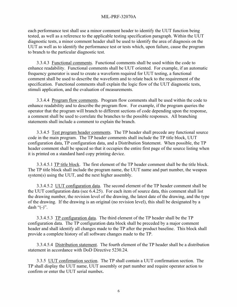
each performance test shall use a minor comment header to identify the UUT function being tested, as well as a reference to the applicable testing specification paragraph. Within the UUT diagnostic tests, a minor comment header shall be used to identify the area of diagnosis on the UUT as well as to identify the performance test or tests which, upon failure, cause the program to branch to the particular diagnostic test. 3.3.4.3 Functional comments. Functional comments shall be used within the code to enhance readability. Functional comments shall be UUT oriented. For example, if an automatic frequency generator is used to create a waveform required for UUT testing, a functional comment shall be used to describe the waveform and to relate back to the requirement of the specification. Functional comments shall explain the logic flow of the UUT diagnostic tests, stimuli application, and the evaluation of measurements. 3.3.4.4 Program flow comments. Program flow comments shall be used within the code to enhance readability and to describe the program flow. For example, if the program queries the operator that the program will branch to different sections of code depending upon the response, a comment shall be used to correlate the branches to the possible responses. All branching statements shall include a comment to explain the branch. 3.3.4.5 Test program header comments. The TP header shall precede any functional source code in the main program. The TP header comments shall include the TP title block, UUT configuration data, TP configuration data, and a Distribution Statement. When possible, the TP header comment shall be spaced so that it occupies the entire first page of the source listing when it is printed on a standard hard copy printing device. 3.3.4.5.1 TP title block. The first element of the TP header comment shall be the title block. The TP title block shall include the program name, the UUT name and part number, the weapon system(s) using the UUT, and the next higher assembly. 3.3.4.5.2 UUT configuration data. The second element of the TP header comment shall be the UUT configuration data (see 6.4.25). For each item of source data, this comment shall list the drawing number, the revision level of the drawing, the latest date of the drawing, and the type of the drawing. If the drawing is an original (no revision level), this shall be designated by a dash “(-)”. 3.3.4.5.3 TP configuration data. The third element of the TP header shall be the TP configuration data. The TP configuration data block shall be preceded by a major comment header and shall identify all changes made to the TP after the product baseline. This block shall provide a complete history of all software changes made to the TP.
3.3.4.5.4 Distribution statement. The fourth element of the TP header shall be a distribution statement in accordance with DoD Directive 5230.24. 3.3.5 UUT confirmation section. The TP shall contain a UUT confirmation section. The TP shall display the UUT name, UUT assembly or part number and require operator action to confirm or enter the UUT serial number.

MIL-PRF-32070A
7
3.3.6 Testing sequence. 3.3.6.1 TPS resource items. The TP shall display the TPH items required for testing the UUT. TPS and UUT Data Sheet, when selected, shall be displayed. This data shall include but not be limited to the ID part number and nomenclature, cable part numbers and quantities, accessories required, and any additional equipment needed to execute the TP. It shall display any CAUTIONS and/or WARNINGS and other safety messages as applicable. It shall identify supporting UUT documentation (for example, technical manuals (TM) reference, parts lists). It shall display the approximate End-To-End/GO CHAIN execution/run time. 3.3.6.2 ATE survey tests. When selected, this test group will, at a minimum, exercise and evaluate the ATE instruments that the TP will utilize during performance testing of the UUT. At the completion of this test group, the TP shall return to the MAIN MENU (see 6.4.3). 3.3.6.3 TPH pre-performance testing. The following three TPH pre-performance tests shall precede the UUT tests. These tests shall not damage the ATE or UUT and shall be in the following order: a. TPH ID hookup. The TPH ID hookup shall display the TPH connections on the ATE display. All required hardware shall be identified by part number and/or reference designator. All connections made between the TPH and the ATE shall be identified on the ATE display (for example, system interconnect and test set-up diagrams). b. TPH signature test. The TPH signature test shall confirm that the correct TPH is connected to the ATE prior to a TPH Safe-To-Turn-On (STTO) testing sequence. c. TPH Safe-To-Turn-On tests. The TPH STTO tests shall check for conditions on power pins, power busses, or power switching assemblies that may cause damage to the TPH or the ATE. 3.3.6.4 TPH performance test. The TPH performance test shall functionally test and evaluate the TPH. If a failure is detected, the TP will halt any further testing, including UUT testing. The TP shall direct the operator to execute the TPH diagnostics to effect repair of the TPH. At the completion of this test group, the TP shall return to the MAIN MENU. The TP shall: a. contain modules that provide test segregation to allow verification of applicable TPH for testing a specific UUT with the UUT disconnected (for example, wraparound test using shorting plugs or cables). b. have a run time interval not greater than ten minutes for each performance module and/or entry point.
c. detect 100 percent of detectable TPH faults, including faulty wire paths. d. allow the ATE operator to repeat/cycle each test or test sequence if more than one

MIL-PRF-32070A
8
individual test is required to set up a test condition. A TPH GOOD message shall not result if a test is repeated due to a failed performance test. e. be performed without removing TPH covers, using TPH extender boards, or probing of the TPH. f. not require an additional interface device (ID). 3.3.6.5 TPH diagnostic test. The TPH diagnostic test shall: a. isolate detected faults to either (1) a single component, (2) a single non-repairable assembly, or (3) a group of components in the case of bus failures or parallel component implementation. The failed component(s) shall be logged and displayed. b. fault isolate to the failed wire path. All failed component(s) shall be logged and displayed. c. by way of TPH design, not require probing, adjustment, and alignment. d. have the capability to reprogram all programmable TPH components via operator selectable routines in case of component failure or firmware updates. 3.3.6.6 TP termination. When selected, this test shall ensure that all instrument stimuli have been removed, measurement instruments are disconnected, and UUT power is properly removed prior to terminating the TP and returning to the run-time environment. 3.3.7 UUT testing. 3.3.7.1 UUT pre-performance tests. UUT tests shall consist of four parts in the following order. a. UUT startup. At start of UUT test, the operator shall be instructed to enter the serial number of UUT under test. b. UUT hookup. The UUT hookup test shall display the UUT connections on the ATE display. All required hardware shall be identified by part number and/or reference designator. All connections made between the UUT, TPH and the ATE shall be identified on the ATE display (for example, system interconnect and test set-up diagrams). c. UUT signature test. The UUT pre-performance test shall perform a signature test to confirm that the correct UUT is connected to the ATE prior to the UUT STTO testing sequence. d. UUT Safe-To-Turn-On tests. A UUT STTO test shall check for conditions on power pins, power busses, or power switching assemblies that may cause damage to the UUT, TPH, or ATE.

MIL-PRF-32070A
9
3.3.7.2 UUT performance test. The UUT performance test shall functionally test and evaluate the UUT for compliance with the UUT’s operational specifications. If the UUT successfully completes end-to-end (ETE) testing, the TP shall log all test results. The printout shall also display, as a minimum, a message stating ALL TESTS PASSED, the UUT part number, serial number, date and time. If a failure is detected, the TP shall notify the operator of the failure. The TP shall branch to diagnostics testing of the faulted circuit. Upon the completion of the diagnostic testing and evaluation, the TP shall display a fault ambiguity group identifying, in most logical order, the defective component(s) and shall log all test results. The TP shall provide for an option to print test results. The printout shall display, as a minimum, a message stating UUT Failed End-To-End Testing, the UUT part number, serial number, date and time, the test results data and faulted components. At the completion of this test group, the TP shall return to the MAIN MENU. The UUT TP shall: a. have an ETE test run time less than 60 minutes for WRA/LRU UUTs and less than 15 minutes for SRA/SRU UUTs, with no faults being detected. The ETE test time shall be measured from the start of UUT performance tests to the display of UUT PASSED ALL PERFORMANCE TESTS, not to include manual operator action time and TPS setup time. b. successfully execute an ETE test before the applicable message specified in Appendix B is displayed on the ATE. c. test all redundant (identical parallel) circuitry. d. automatically detect 100 percent of detectable faults in the UUT, including redundant circuitry (see 6.4.8). e. have a test hierarchy applied to reduce the UUT mean time to repair by first testing the least reliable assemblies, subassemblies and components of the UUT (see 6.3.1) (for example, internal power supplies, internal clocks, input-output busses. This test hierarchy shall also consider the use of built in test/built in test equipment (BIT/BITE) (see 6.3.5)). f. conclude performance testing with a failure message for any out-of-tolerance measurement. This message shall identify the cause of failure and provide the recommended maintenance action, lead an operator to additional diagnostic tests, or lead an operator to specific UUT alignment procedures. The applicable message as specified in Appendix B shall be displayed. g. allow the ATE operator to repeat or cycle each failed test and test condition. A UUT GOOD message shall not result if a test is repeated due to a failed performance test.
h. be performed without removing UUT covers, using UUT extender boards, or probing of the UUT except when adjustment and alignment procedures are required during the performance test.
MIL-PRF-32070A
10
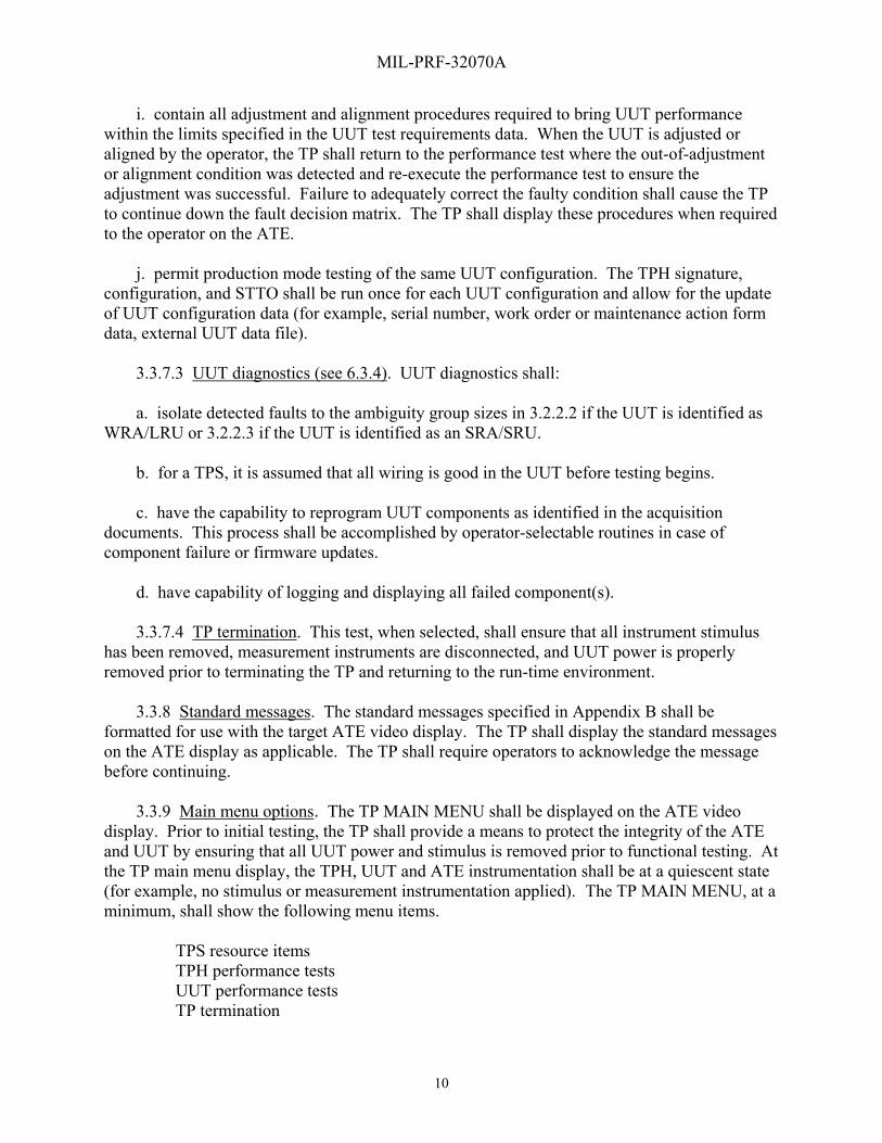
i. contain all adjustment and alignment procedures required to bring UUT performance within the limits specified in the UUT test requirements data. When the UUT is adjusted or aligned by the operator, the TP shall return to the performance test where the out-of-adjustment or alignment condition was detected and re-execute the performance test to ensure the adjustment was successful. Failure to adequately correct the faulty condition shall cause the TP to continue down the fault decision matrix. The TP shall display these procedures when required to the operator on the ATE. j. permit production mode testing of the same UUT configuration. The TPH signature, configuration, and STTO shall be run once for each UUT configuration and allow for the update of UUT configuration data (for example, serial number, work order or maintenance action form data, external UUT data file). 3.3.7.3 UUT diagnostics (see 6.3.4). UUT diagnostics shall: a. isolate detected faults to the ambiguity group sizes in 3.2.2.2 if the UUT is identified as WRA/LRU or 3.2.2.3 if the UUT is identified as an SRA/SRU. b. for a TPS, it is assumed that all wiring is good in the UUT before testing begins. c. have the capability to reprogram UUT components as identified in the acquisition documents. This process shall be accomplished by operator-selectable routines in case of component failure or firmware updates. d. have capability of logging and displaying all failed component(s). 3.3.7.4 TP termination. This test, when selected, shall ensure that all instrument stimulus has been removed, measurement instruments are disconnected, and UUT power is properly removed prior to terminating the TP and returning to the run-time environment. 3.3.8 Standard messages. The standard messages specified in Appendix B shall be formatted for use with the target ATE video display. The TP shall display the standard messages on the ATE display as applicable. The TP shall require operators to acknowledge the message before continuing. 3.3.9 Main menu options. The TP MAIN MENU shall be displayed on the ATE video display. Prior to initial testing, the TP shall provide a means to protect the integrity of the ATE and UUT by ensuring that all UUT power and stimulus is removed prior to functional testing. At the TP main menu display, the TPH, UUT and ATE instrumentation shall be at a quiescent state (for example, no stimulus or measurement instrumentation applied). The TP MAIN MENU, at a minimum, shall show the following menu items. TPS resource items TPH performance tests UUT performance tests TP termination

MIL-PRF-32070A
11
Additional menus and sub-menu items shall be in accordance with the target ATE style requirements (see 6.2.e). 3.3.10 Test results. The TP shall provide automatic logging of test results and allow an option to print test results or messages. 3.3.11 Graphics. The TP shall provide on the ATE display graphics of specific operations, procedures, and diagrams required for the ATE operator to conduct testing of the designated UUT (for example, the systems interconnect diagrams and test set-up diagrams). All adjustment locations, alignment locations, test point locations, designated probe point locations, and additional test information, as they appear on the UUT, shall be displayed. All potentially unsafe hazardous points associated with test and diagnosis of the UUT or the TPH shall be identified by warning and caution messages. 3.4 Hardware requirements. 3.4.1 Nomenclature. The following TPH items, as a minimum, shall be identified as the standard nomenclatures. Accessory set Ancillary equipment Cable assembly (set) Holding fixture Interface Device (ID) Test fixture If additional standard nomenclature is required, the H-6 catalog should be consulted. 3.4.2 Accessory set. An accessory set, if required, shall be provided as part of the TPS (see 6.4.1). 3.4.3 Ancillary equipment. Ancillary equipment, if required, shall be provided as part of the TPS (see 6.4.2). 3.4.4 Cable assemblies (see 6.4.4). 3.4.4.1 Cable design. The cable design shall: a. protect cables and wiring from breakage by providing strain relief so that the weight of a connector, or a cable assembly and connector, does not damage the UUT, the ATE, or the TPH. b. have cable connectors that are free of potting compound. c. not use cable ties on wire bundles within a protective covering. d. have assemblies constructed such that a minimum of three inches of wire shall be

MIL-PRF-32070A
12
exposed between the cable covering and the connector when the connector shell is removed (see 6.3.3). e. not have woven, braided wiring, or ribbon cable used for ID external connections. f. be repairable by the end user using standard shop tools. Any special tools shall be provided as part of the TPH. g. contain no electrical components. h. have individual wires of length and flexibility such as to prevent damage when being bent during use, repair, and storage. i. have connector shells to protect any exposed contacts from damage when protective covers are removed. 3.4.4.2 Cable assembly branching limit. A maximum of one branch per cable assembly shall be used. The maximum number of connectors per cable assembly shall be three. 3.4.5 Holding fixture (HF). The size, mounting, and weight of holding fixtures shall be compatible with the target ATE and the maximum weight of the holding fixture shall be 74 pounds. The holding fixture shall be labeled with the actual weight and specify a two-person lift if the weight is over 37 pounds (see 6.4.13). 3.4.6 Interface device (ID) (see 6.4.14). The ID shall: a. require only one person to mount it onto the ATE interface. The weight of the ID shall be not greater than 37 pounds. b. have signal and power grounds that do not degrade the performance of the TPS. The TPH grounding scheme shall be optimized for the target ATE. c. adhere to the requirements of MIL-STD-1472 for external connectors, including the following: i) the mating connector-engaging mechanism shall lock or tighten in its fully closed position. Identical TPH connectors shall be keyed differently. ii) each external connector on TPH items shall be provided with an attachable or attached protective cover. iii) connector placement shall not require connecting or disconnecting any adjacent connector during mate or demate actions. iv) power connector contacts supplying power shall have socket contacts while those receiving power shall have pin contacts.

MIL-PRF-32070A
13
v) individual connector contacts shall be removable and replaceable without removing other contacts. d. incorporate its internal wiring scheme in such a manner that the wiring will not be damaged during normal maintenance. e. not use wire wrap within the TPH. f. not exceed the requirements of the target ATE for the moment of force at the ATE/ID interface, with the cables attached, including when the UUT, and any other required items, are connected. 3.4.7 Test fixture (TF) (see 6.4.19). The test fixture shall: a. have a maximum weight of 74 pounds. The test fixture shall be labeled with the actual weight and specify a two-person lift if the weight is over 37 pounds. b. be of a size, mounting, and weight that is compatible with the target ATE. c. have signal and power grounds that do not degrade the performance of the TPS. The TPH grounding scheme shall be optimized for the target ATE. d. adhere to the requirements of MIL-STD-1472 for external connectors, including the following:
i) the mating connector-engaging mechanism shall lock or tighten in its fully closed position and identical TPH connectors shall be keyed differently. ii) each external connector on TPH items shall be provided with an attachable or attached protective cover. iii) connector placement shall not require connecting or disconnecting any adjacent connector during mate or demate actions. iv) power connector contacts supplying power shall have socket contacts while those receiving power shall have pin contacts. v) individual connector contacts shall be removable and replaceable without removing other contacts.
e. meet the requirement that the internal wiring shall not be damaged during normal maintenance. f. not use wire wrap within the test fixture.

MIL-PRF-32070A
14
3.4.8 Item Unique Identification (IUID) marking of U.S. military property. Items shall be identified in accordance with MIL-STD-130. 3.4.9 Product marking. Identification shall be permanently affixed to a non-removable part of the ID, test fixture and holding fixtures. Permanent identification shall be provided on each cable, except for multi-purpose cables. Each mating connector shall be permanently identified with “J” or “P” reference designators in accordance with ASME Y14.44. 3.4.10 Maintainability. TPH items shall not require periodic maintenance or calibration. The TPH design shall allow for item repair in less than 45 minutes. This time shall include all clock time to conduct removal of assemblies and subassemblies, component replacement actions, wiring repairs and incidental repair actions. Fault detection, isolation and subsequent TPH verification shall not be included in maximum time to repair calculations. 3.4.11 Reliability. 3.4.11.1 Mean-time-between-failure (MTBF). The MTBF of the TPH, in any combination and in any configuration of TPH items necessary to comply with test, diagnosis, and alignment requirements stated herein, shall be greater than 10,000 operating hours (excluding external connectors identified in table IV). Operating hours shall include the sum of all times the item is used for TPH hookup, tests, diagnosis, alignments, and adjustments. 3.4.11.2 Connector durability. The number of mating and de-mating cycles without failure shall meet or exceed the minimum requirements in table IV.
TABLE IV. Mating/de-mating requirements.
Utilization Minimum number of mating/de-mating cycles
ID to ATE interface connection
Conform to the requirement of target ATE system.
External TPH connector 500
UUT interface connector Conform to the UUT requirement
Internal ID (inside) connection 100
RF cables 500
3.4.12 Safety. The TPS when connected, operated (in the “OFF” or in any operational mode), and disconnected, shall comply with the safety requirements of IEC-61010-1 and use the electrostatic discharge protection information in JESD-625. Suitable protective measures are defined in table V (see 6.5).

MIL-PRF-32070A
15
TABLE V. Protective measures.
Voltage range
1/
Type of Protection
None
Guards &
barriers
Enclosures
Marking Interlocks Discharge devices 5/
Caution
2/
Warning
3/
Danger
4/ Bypassable
Non-Bypassable
Automatic Shorting
rods
0 to 30V X X
30 - 70 V X X X X
70 to 500V
X X X X X
>500V X X X X X X
1/ Voltage range applies to total differential voltage.
2/ Under the marking CAUTION, identify maximum voltage (for example, 34 VDC).
3/ Under the marking WARNING, identify maximum voltage (for example, 110 VAC).
4/ Under the marking DANGER, add the words HIGH VOLTAGE and identify maximum voltage (for example, 550 VAC)
5/ For voltages of 70 to 500 V and voltages greater than 500 V, both automatic and shorting rod discharge devices shall be used.
3.4.13 Workmanship.
3.4.13.1 Soldering. Electrical and electronic equipment shall be assembled, soldered, and
cleaned in accordance with IPC J-STD-001.
3.4.13.2 Cleaning. After fabrication, parts and assembled equipment shall be cleaned of smudges; loose, spattered, or excess solder; weld metal; metal chips; mold release agents; or any other foreign material which detracts from the intended operation, function, or appearance of the equipment.
3.4.13.3 Threaded parts or devices. Screws, nuts, and bolts shall be firmly secured, of proper length, and show no evidence of cross threading, mutilation, or detrimental or hazardous burrs.
3.4.13.4 Wiring. Wires and cables shall be positioned or protected to avoid contact with rough or irregular surfaces and sharp edges, and to avoid damage to conductors or adjacent parts.
3.4.13.5 Shielding. Shielding on wires and cables shall be secured in a manner that will
prevent contacting or shorting exposed current-carrying parts. The ends of the shielding or braid shall be secured to prevent fraying.
MIL-PRF-32070A
16
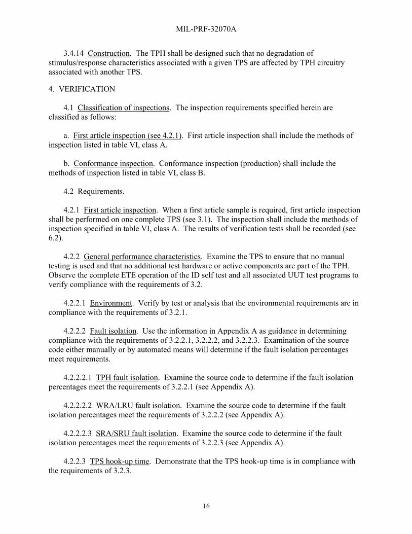
3.4.14 Construction. The TPH shall be designed such that no degradation of stimulus/response characteristics associated with a given TPS are affected by TPH circuitry associated with another TPS. 4. VERIFICATION 4.1 Classification of inspections. The inspection requirements specified herein are classified as follows: a. First article inspection (see 4.2.1). First article inspection shall include the methods of inspection listed in table VI, class A. b. Conformance inspection. Conformance inspection (production) shall include the methods of inspection listed in table VI, class B. 4.2 Requirements. 4.2.1 First article inspection. When a first article sample is required, first article inspection shall be performed on one complete TPS (see 3.1). The inspection shall include the methods of inspection specified in table VI, class A. The results of verification tests shall be recorded (see 6.2). 4.2.2 General performance characteristics. Examine the TPS to ensure that no manual testing is used and that no additional test hardware or active components are part of the TPH. Observe the complete ETE operation of the ID self test and all associated UUT test programs to verify compliance with the requirements of 3.2. 4.2.2.1 Environment. Verify by test or analysis that the environmental requirements are in compliance with the requirements of 3.2.1. 4.2.2.2 Fault isolation. Use the information in Appendix A as guidance in determining compliance with the requirements of 3.2.2.1, 3.2.2.2, and 3.2.2.3. Examination of the source code either manually or by automated means will determine if the fault isolation percentages meet requirements. 4.2.2.2.1 TPH fault isolation. Examine the source code to determine if the fault isolation percentages meet the requirements of 3.2.2.1 (see Appendix A). 4.2.2.2.2 WRA/LRU fault isolation. Examine the source code to determine if the fault isolation percentages meet the requirements of 3.2.2.2 (see Appendix A). 4.2.2.2.3 SRA/SRU fault isolation. Examine the source code to determine if the fault isolation percentages meet the requirements of 3.2.2.3 (see Appendix A). 4.2.2.3 TPS hook-up time. Demonstrate that the TPS hook-up time is in compliance with the requirements of 3.2.3.

MIL-PRF-32070A
17
4.2.2.4 Operational footprint. Measure the overall height, width, and length of the TPH when it is connected to the target ATE to determine compliance with the requirements of 3.2.4. 4.2.2.5 Usability of TPS for Operating personnel. Examine all elements of the TPS (Test Program Instruction (TPI), Technical Manuals (TMs), displays, etc.) to determine usability by operating personnel in 3.2.5. 4.2.2.6 Technical architecture interface requirements. To determine compliance with the requirements of 3.2.6, examine the TPS code or other software to verify that the implemented technical architecture elements of the TP have not been bypassed by any type of direct communication to another interface or layer further in the process. 4.2.2.7 Test accuracy ratio (TAR). Verify the TAR by examining the source code test setups to determine compliance with the requirements of 3.2.7. 4.2.2.8 TPS transportability. Perform the following tests to verify compliance with requirements of 3.2.8. First, perform an ETE test on one known good UUT, using the TPS with the target ATE. Second, perform an ETE test using the same UUT and TPS on a different serial number ATE of the same configuration. Third, perform an ETE test using the TPS on a different serial number of the UUT on an ATE of the same configuration. When a TPS is host to more than one UUT, the above cycle shall be performed for each UUT. 4.2.2.9 UUT and ATE integrity. Examine the source code and run the TP to ensure that the operation of the UUT and ATE is in compliance with the requirements of 3.2.9. 4.2.3 Software requirements. 4.2.3.1 TP format. Examine the TP format to determine compliance with the target ATE style requirements as specified in 3.3.1. 4.2.3.2 Naming convention. Examine the naming conventions used in the TP to ensure compliance with the requirements of 3.3.2. 4.2.3.3 Procedures. Examine the TP to ensure that standard procedures and procedure names used are in compliance with the requirements of 3.3.3. 4.2.3.4 Comments. 4.2.3.4.1 Major comments. Examine the source code and demonstrate by running the TPS to ensure that the format used for the major comment headers is compliant with the requirements specified in 3.3.4.1. 4.2.3.4.2 Minor comments. Examine the source code and demonstrate by running the TPS to ensure that the format used for the minor comment headers is compliant with the requirements specified in 3.3.4.2.
MIL-PRF-32070A
18
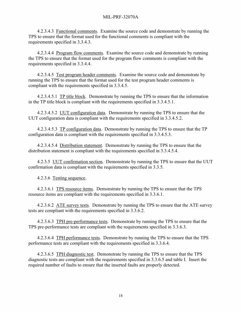
4.2.3.4.3 Functional comments. Examine the source code and demonstrate by running the TPS to ensure that the format used for the functional comments is compliant with the requirements specified in 3.3.4.3. 4.2.3.4.4 Program flow comments. Examine the source code and demonstrate by running the TPS to ensure that the format used for the program flow comments is compliant with the requirements specified in 3.3.4.4. 4.2.3.4.5 Test program header comments. Examine the source code and demonstrate by running the TPS to ensure that the format used for the test program header comments is compliant with the requirements specified in 3.3.4.5. 4.2.3.4.5.1 TP title block. Demonstrate by running the TPS to ensure that the information in the TP title block is compliant with the requirements specified in 3.3.4.5.1. 4.2.3.4.5.2 UUT configuration data. Demonstrate by running the TPS to ensure that the UUT configuration data is compliant with the requirements specified in 3.3.4.5.2. 4.2.3.4.5.3 TP configuration data. Demonstrate by running the TPS to ensure that the TP configuration data is compliant with the requirements specified in 3.3.4.5.3. 4.2.3.4.5.4 Distribution statement. Demonstrate by running the TPS to ensure that the distribution statement is compliant with the requirements specified in 3.3.4.5.4. 4.2.3.5 UUT confirmation section. Demonstrate by running the TPS to ensure that the UUT confirmation data is compliant with the requirements specified in 3.3.5. 4.2.3.6 Testing sequence. 4.2.3.6.1 TPS resource items. Demonstrate by running the TPS to ensure that the TPS resource items are compliant with the requirements specified in 3.3.6.1. 4.2.3.6.2 ATE survey tests. Demonstrate by running the TPS to ensure that the ATE survey tests are compliant with the requirements specified in 3.3.6.2. 4.2.3.6.3 TPH pre-performance tests. Demonstrate by running the TPS to ensure that the TPS pre-performance tests are compliant with the requirements specified in 3.3.6.3. 4.2.3.6.4 TPH performance tests. Demonstrate by running the TPS to ensure that the TPS performance tests are compliant with the requirements specified in 3.3.6.4. 4.2.3.6.5 TPH diagnostic test. Demonstrate by running the TPS to ensure that the TPS diagnostic tests are compliant with the requirements specified in 3.3.6.5 and table I. Insert the required number of faults to ensure that the inserted faults are properly detected.

MIL-PRF-32070A
19
4.2.3.6.6 TP termination. Demonstrate by running the TPS to ensure that the TP termination requirements of 3.3.6.6 have been satisfied. 4.2.3.7 UUT testing.
4.2.3.7.1 UUT pre-performance tests. Demonstrate by running the TPS to ensure that the UUT pre-performance tests are compliant with the requirements specified 3.3.7.1. 4.2.3.7.2 UUT performance tests. Demonstrate by running the TPS to ensure that the TPS performance tests are compliant with the requirements specified 3.3.7.2. 4.2.3.7.3 UUT diagnostics. Demonstrate by running the TPS to ensure that the UUT diagnostic tests are compliant with the requirements specified in 3.3.7.3. Insert the required number of faults to ensure that the inserted faults are properly detected. 4.2.3.7.4 TP termination. Demonstrate by running the TPS to ensure that the TP termination requirements of 3.3.7.4 have been satisfied. 4.2.3.8 Standard messages. Demonstrate by running the TPS to ensure that the standard messages on the target ATE display are in compliance with the requirements of 3.3.8. 4.2.3.9 Main menu options. Demonstrate by running the TPS to ensure that the main menu options of the target ATE are compliant with the requirements of 3.3.9. 4.2.3.10 Test results. Demonstrate by running the TPS to ensure that the requirements of 3.3.10 have been satisfied. 4.2.3.11 Graphics. Demonstrate by running the TPS to ensure that the requirements of 3.3.11 have been satisfied. 4.2.4 Hardware requirements. 4.2.4.1 Nomenclature. Examine the nomenclature to determine compliance with the requirements of 3.4.1. 4.2.4.2 Accessory set. Examine each accessory set for compliance with the requirements of 3.4.2. 4.2.4.3 Ancillary equipment. Examine the ancillary equipment for compliance with the requirements of 3.4.3. 4.2.4.4 Cable assemblies. 4.2.4.4.1 Cable design. Examine each cable assembly for compliance with the requirements of 3.4.4.1. 4.2.4.4.2 Cable assembly branching limit. Examine each cable assembly for compliance

MIL-PRF-32070A
20
with the requirements of 3.4.4.2. 4.2.4.5 Holding fixture (HF). Examine the HF to ensure compliance with the requirements of 3.4.5. 4.2.4.6 Interface device (ID). Examine the ID to ensure compliance with the requirements of 3.4.6. 4.2.4.7 Test fixture (TF). Examine the TF to ensure compliance with the requirements of 3.4.7. 4.2.4.8 IUID marking of US military property. Examine the hardware items to ensure that the IUID marking is compliant with 3.4.8. 4.2.4.9 Product marking. Examine the ID to ensure compliance with the requirements of 3.4.9. 4.2.4.10 Maintainability. Verify by test that the maintainability requirements of 3.4.10 have been satisfied. 4.2.4.11 Reliability. 4.2.4.11.1 Mean-time-between-failure (MTBF). Verify by test that the MTBF satisfies the requirements of 3.4.11.1. 4.2.4.11.2 Connector durability. Verify by examination that connector durability satisfies the requirements of 3.4.11.2. 4.2.4.12 Safety. Verify by demonstration that the safety conditions are compliant with the requirements of 3.4.12.
4.2.4.13 Workmanship.
4.2.4.13.1 Soldering. Examine soldering connections to ensure compliance with the requirements of 3.4.13.1.
4.2.4.13.2 Cleaning. Examine the hardware to ensure a thorough cleaning of the product
has been performed and is compliant with the requirements of 3.4.13.2. 4.2.4.13.3 Threaded parts or devices. Examine the hardware to ensure compliance with the
requirements of 3.4.13.3. 4.2.4.13.4 Wiring. Examine the hardware to ensure compliance with the requirements of
3.4.13.4. 4.2.4.13.5 Shielding. Examine the shielding on wires and cables to ensure compliance with
the requirements of 3.4.13.5.

MIL-PRF-32070A
21
4.2.4.14 Construction. Demonstrate and test that the requirements of 3.4.14 have been satisfied. During testing of each TPH sub-set, observe for any test performance issues related to any other TPH sub-set. Review the TPS software to determine if the circuitry of any associated TPS sub-set is coupled in a manner that causes TPS performance issues. 5. PACKAGING 5.1 Packaging. For acquisition purposes, the packaging requirements shall be as specified in the contract or order (see 6.2). When packaging of materiel is to be performed by DoD or in-house contractor personnel, these personnel need to contact the responsible packaging activity to ascertain packaging requirements. Packaging requirements are maintained by the Inventory Control Point’s packaging activities within the Military Service or Defense Agency, or within the military service’s system commands. Packaging data retrieval is available from the managing Military Department’s or Defense Agency’s automated packaging files, CD-ROM products, or by contacting the responsible packaging activity. 6. NOTES (This section contains information of a general or explanatory nature which may be helpful, but is not mandatory.) 6.1 Intended use. TPSs described herein consist of software, hardware, and operating instructions and are intended to be used with Government-furnished ATE for testing, diagnosing, adjusting, and aligning UUTs. Military systems are tested and diagnosed using a combination of ATE and TPSs. TPSs are used in the maintenance of military avionics, weapon systems, and ground-based equipment, and do not have commercial applications. 6.2 Acquisition requirements. Acquisition documents should specify the following: a. Title, number, and date of this specification. b. When first article inspection is required (see 3.1). c. Operational and storage environmental requirements of the target ATE (for example, electromagnetic interference, shock and vibration) (see 3.2.1). d. The operational footprint (see 3.2.4). e. The target ATE/TP style requirements (for example, TPS Programming Guide) (see 3.2.6 and 3.3.1). . f. UUTs as WRA/LRU or SRA/SRU for testing purposes. g. How the tests are to be conducted and results of the verification recorded (see 4.2.1). h. Packaging requirements (see 5.1).

MIL-PRF-32070A
22
6.3 Successful techniques. The following non-binding guidance may be helpful in satisfying the requirements of section 3.
6.3.1 Reliability and test hierarchy. Faults with the highest probability of occurrence may be derived from UUT Failure Mode, Effects and Analysis (FMEA) or other available UUT reliability data. 6.3.2 Electromagnetic interference (EMI). EMI shielding gaskets, as applicable, should be used on TPH enclosure covers. TPH enclosure covers containing wire mesh screens for cooling may also provide EMI shielding. Connectors may incorporate a conductive elastomer (see 3.2.1). 6.3.3 Cable assemblies. Cables with multiple pin connectors may be protected by annular convolution type tubing. Cable outer jackets may be attached to connector shells by a screw-on coupling. 6.3.4 UUT diagnostics. Removal of UUT covers, use of UUT extender boards and probing of the UUT is permitted during diagnostic testing of the UUT. 6.3.5 Built-In Test (BIT)/Built-In Test Equipment (BITE). UUT BIT/BITE execution is permitted. If a UUT BIT/BITE is used for fault detection, the TP should display the applicable message when a fault is detected by the TP (see 3.3.7.2.e). 6.4. Definitions. 6.4.1 Accessory set. Various hardware items such as special tools, extender cards, adapters, probes, cable assemblies, indicator overlays, alignment fixtures, and other items to support testing of UUTs on an ATE as required by the TPS (see 3.4.2). 6.4.2 Ancillary equipment. Equipment external to test program hardware required to complete testing of a UUT, and specifically required for a UUT TPS (for example, a load assembly). Common shop equipment is not ancillary equipment (see 3.4.3). 6.4.3 ATE survey test. A test designed to check that the ATE resources required by the TPS are present and operational for TP requirements. The ATE survey test is normally an optional test performed at the operator’s discretion (see 3.3.6.2). 6.4.4 Cable assemblies. A specifically designed item, with or without branches, having one or more ends processed or terminated in fittings for use between UUTs, ATE, and IDs (see 3.4.4). 6.4.5 Cable assembly set. A cable assembly set is a grouping of items having the same basic name for use with two or more cable assemblies. 6.4.6 Component. Single part or a replaceable non-repairable sub-assembly, these parts or sub-assemblies can be plug-in, chassis mounted, or hardwired. In the case of a bus failure or

MIL-PRF-32070A
23
parallel component implementation (for example nodal failure), the bus or parallel component components are considered to be a single component when calculating ambiguity group size (see Appendix A). 6.4.7 Demonstration. Demonstration is an element of verification which generally denotes the actual operation, adjustment, or re-configuration of items to provide evidence that the designed functions were accomplished under specific scenarios. The items may be instrumented and quantitative limits of performance monitored. 6.4.8 Detectable fault. A detectable fault is a fault that can be detected using the functionality of the ATE/TPS (see 3.3.7.2.d). 6.4.9 Diagnostic tests. Diagnostic tests are a set of tests that isolates and identifies faults detected by the performance tests. 6.4.10 Examination. An element of verification and inspection consisting of investigation of items without use of special laboratory appliances or procedures, to determine conformance to those specified requirements by such investigations. Examination is generally nondestructive and typically includes the use of sight, hearing, smell, touch, and taste; simple physical manipulation; mechanical and electrical gauging and measurement; and other forms of investigation. 6.4.11 Fault. Degradation outside of normal performance limits on UUT operation due to maladjustment, misalignment, component tolerance drift, or a failure of a component(s) 6.4.12 Fault isolation (FI) percentages. FI is the number of ambiguity groups with 'n' items divided by the total number of ambiguity groups. The size of a group is determined by quantity of items within a group. Items are subassemblies or components, depending on level of fault isolation required for the UUT. 6.4.13 Holding fixture (HF). An HF is a specifically designed hardware device used to maintain proper positioning of a UUT during testing. The holding fixture provides the means to support and restrain the UUT to prevent damage to or performance degradation of the UUT during testing. The holding fixture provides access for cooling if required by the UUT. The holding fixture has no electrical interface with the UUT, ID, or ATE. 6.4.14 Interface device (ID). An ID is a device that provides the required mechanical, electrical, hydraulic, pneumatic, radiated, or optical interconnections between a UUT and ATE to allow execution of the test program (see 3.4.6). 6.4.15 Performance tests. Performance tests are a sequence of tests that automatically detects and identifies the presence of all detectable faults, misalignments, or mis-adjustments. 6.4.16 Receiver fixture interface. This interface resides on the ATE and provides the means to accomplish the mechanical and electrical connections between the UUT stimulus/response signals passing through the UUT’s unique ID and the signals to and from the ATE test

MIL-PRF-32070A
24
instrumentation. These signals are applied directly to the ATE test instrument or through an ATE hardware switch. 6.4.17 Test. A procedure or action taken to determine under real or simulated conditions the capabilities, limitations, characteristics, effectiveness, reliability or suitability of a material, device, system, or method. 6.4.18 Test Accuracy Ratio (TAR). The TAR maximum permitted error of the unit to be measured or calibrated divided by the known error of the measuring or generating device used to perform the measurement. For example, if it is required that a system or equipment output parameter be accurate to within 8 percent (maximum permitted error) and a known accuracy (maximum known error) of the measuring device used to measure the output parameter is 2 percent, then the TAR is 4 (see 3.2.7). 6.4.19 Test Fixture (TF). A TF is a fixture that provides additional circuitry to resolve incompatibilities between a UUT and an ATE, which is not appropriate for inclusion in an ID due to weight, size, signal conditioning or heat limitations. It may also be used as a fixture to secure a UUT (see 3.4.7). 6.4.20 Test Program (TP). A coded sequence, when executed by an ATE, provides instruction, UUT stimuli, measurements of UUT responses, detection of UUT faults, isolation of UUT faults, and alignment/adjustment procedures for fault correction. The test program is formatted in accordance with the targeted ATE style guides to provide uniformity in the functionality and appearance of the TP (see 3.3.1). 6.4.21 Test Program Hardware (TPH). TPH is various hardware items required by a TPS to function. These may include an ID, or a combination of an ID, cable assembly (set), test fixture(s), holding fixture(s), accessories, and ancillary equipment. 6.4.22 Test Program Set (TPS). A TPS is a collection of hardware, software, and applicable documentation used for testing, fault detection and isolation, maintenance, and any other evaluations of components and equipment (see 3.1). 6.4.23 TPS hook-up time. Time required for setting up the ATE/TPH/TPS configuration for testing a UUT. 6.4.24 TPS transportability. The capability of executing a TPS on all ATE of the same configuration, or on other ATE configurations that include the sufficient instrumentation to execute the TPS (see 3.2.8). 6.4.25 UUT configuration data. The section of comments, preceded by a major comment header, which lists all of the configuration data packages used to provide relevant UUT source data during the development of the TPS (see 3.3.4.5.2). 6.4.26 UUT firmware. Software that is installed on a device in the UUT as read-only computer instructions (see 3.2.9).

MIL-PRF-32070A
25
6.5 Safety. MIL-HDBK-454, guideline 1 provides guidance for safety design criteria and personnel protection. 6.6 Changes from previous issue. Marginal notations are not used in this revision to identify changes with respect to the previous issue due to the extent of the changes. 6.7 Subject term (key word) listing. Ancillary equipment Calculations, Ambiguity Group Size Fault isolation Fixture Fixture, Holding Footprint, operational Interface device Line Replaceable Unit Shop Replaceable Assembly Shop Replaceable Unit Weapons Replaceable Assembly
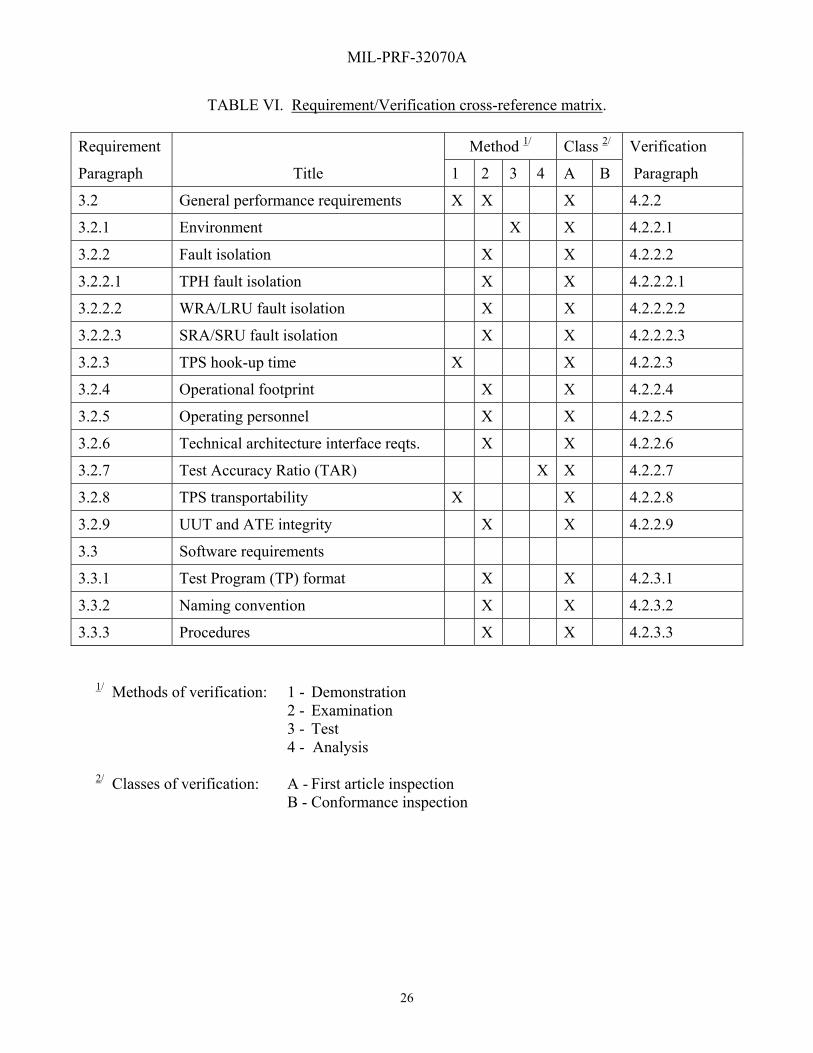
MIL-PRF-32070A
26
TABLE VI. Requirement/Verification cross-reference matrix.
Requirement Method 1/ Class 2/ Verification
Paragraph Title 1 2 3 4 A B Paragraph
3.2 General performance requirements X X X 4.2.2
3.2.1 Environment X X 4.2.2.1
3.2.2 Fault isolation X X 4.2.2.2
3.2.2.1 TPH fault isolation X X 4.2.2.2.1
3.2.2.2 WRA/LRU fault isolation X X 4.2.2.2.2
3.2.2.3 SRA/SRU fault isolation X X 4.2.2.2.3
3.2.3 TPS hook-up time X X 4.2.2.3
3.2.4 Operational footprint X X 4.2.2.4
3.2.5 Operating personnel X X 4.2.2.5
3.2.6 Technical architecture interface reqts. X X 4.2.2.6
3.2.7 Test Accuracy Ratio (TAR) X X 4.2.2.7
3.2.8 TPS transportability X X 4.2.2.8
3.2.9 UUT and ATE integrity X X 4.2.2.9
3.3 Software requirements
3.3.1 Test Program (TP) format X X 4.2.3.1
3.3.2 Naming convention X X 4.2.3.2
3.3.3 Procedures X X 4.2.3.3
1/ Methods of verification: 1 - Demonstration 2 - Examination 3 - Test 4 - Analysis 2/ Classes of verification: A - First article inspection B - Conformance inspection

MIL-PRF-32070A
27
TABLE VI. Requirement/Verification cross-reference matrix – Continued.
Requirement Method 1/ Class 2/ Verification
Paragraph Title 1 2 3 4 A B Paragraph
3.3.4 Comments
3.3.4.1 Major comments X X 4.2.3.4.1
3.3.4.2 Minor comments X X 4.2.3.4.2
3.3.4.3 Functional comments X X 4.2.3.4.3
3.3.4.4 Program flow comments X X 4.2.3.4.4
3.3.4.5 Test program header comments X X 4.2.3.4.5
3.3.4.5.1 TP title block X X 4.2.3.4.5.1
3.3.4.5.2 UUT configuration data X X 4.2.3.4.5.2
3.3.4.5.3 TP configuration data X X 4.2.3.4.5.3
3.3.4.5.4 Distribution Statement X X 4.2.3.4.5.4
3.3.5 UUT confirmation section X X 4.2.3.5
3.3.6 Testing sequence
3.3.6.1 TPS resource items X X 4.2.3.6.1
3.3.6.2 ATE survey tests X X 4.2.3.6.2
3.3.6.3 TPH pre-performance testing X X X 4.2.3.6.3
3.3.6.4 TPH performance test X X X 4.2.3.6.4
3.3.6.5 TPH diagnostic test X X 4.2.3.6.5
3.3.6.6 TP termination X X X 4.2.3.6.6
3.3.7 UUT testing
3.3.7.1 UUT pre-performance tests X X X 4.2.3.7.1
1/ Methods of verification: 1 - Demonstration 2 - Examination 3 - Test 4 - Analysis 2/ Classes of verification: A - First article inspection B - Conformance inspection

MIL-PRF-32070A
28
TABLE VI. Requirement/Verification cross-reference matrix – Continued.
Requirement Method 1/ Class 2/ Verification
Paragraph Title 1 2 3 4 A B Paragraph
3.3.7.2 UUT performance tests X X X 4.2.3.7.2
3.3.7.3 UUT diagnostics X X X X 4.2.3.7.3
3.3.7.4 TP termination X X X 4.2.3.7.4
3.3.8 Standard messages X X 4.2.3.8
3.3.9 Main menu options X X 4.2.3.9
3.3.10 Test Results X X X 4.2.3.10
3.3.11 Graphics X X 4.2.3.11
3.4 Hardware Requirements
3.4.1 Nomenclature X X 4.2.4.1
3.4.2 Accessory set X X X 4.2.4.2
3.4.3 Ancillary set X X X 4.2.4.3
3.4.4 Cable assemblies
3.4.4.1 Cable design X X X 4.2.4.4.1
3.4.4.2 Cable assembly branching limit X X X 4.2.4.4.2
3.4.5 Holding fixture (HF) X X X 4.2.4.5
3.4.6 Interface Device (ID) X X X 4.2.4.6
3.4.7 Test fixture (TF) X X X 4.2.4.7
3.4.8 Item Unique Identification (IUID) Marking of Military Property
X X X 4.2.4.8
3.4.9 Product marking X X X 4.2.4.9
3.4.10 Maintainability X X 4.2.4.10
1/ Methods of verification: 1 - Demonstration 2 - Examination 3 - Test 4 - Analysis 2/ Classes of verification: A - First article inspection B - Conformance inspection

MIL-PRF-32070A
29
TABLE VI. Requirement/Verification cross-reference matrix – Continued.
Requirement Method 1/ Class 2/ Verification
Paragraph Title 1 2 3 4 A B Paragraph
3.4.11 Reliability X X
3.4.11.1 Mean-time-between-failure (MTBF) X X X 4.2.4.11.1
3.4.11.2 Connector durability X X X 4.2.4.11.2
3.4.12 Safety X X 4.2.4.12
3.4.13 Workmanship X
3.4.13.1 Soldering X X X X 4.2.4.13.1
3.4.13.2 Cleaning X X 4.2.4.13.2
3.4.13.3 Threaded parts or devices X 4.2.4.13.3
3.4.13.4 Wiring X X 4.2.4.13.4
3.4.13.5 Shielding X X X 4.2.4.13.5
3.4.14 Construction X X X 4.2.4.14
1/ Methods of verification: 1 - Demonstration 2 - Examination 3 - Test 4 - Analysis 2/ Classes of verification: A - First article inspection B - Conformance inspection
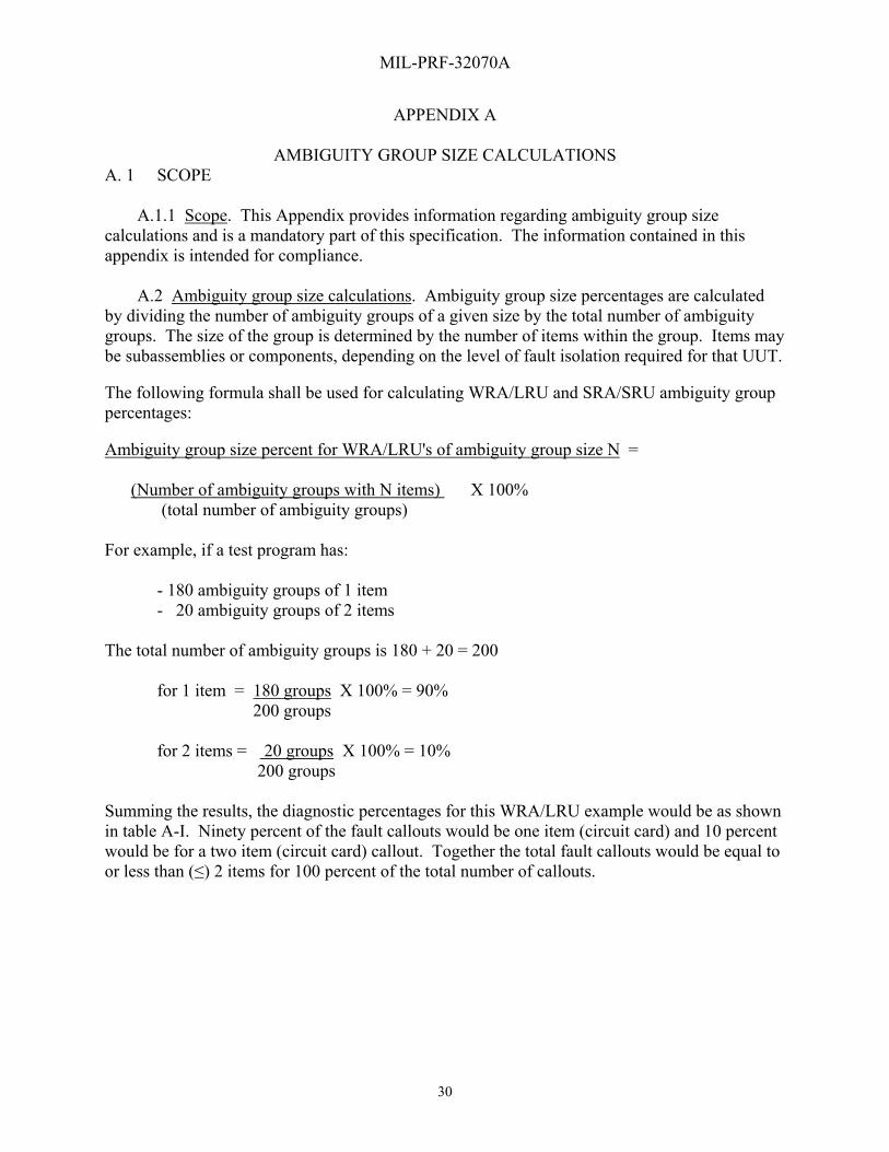
MIL-PRF-32070A
30
APPENDIX A
AMBIGUITY GROUP SIZE CALCULATIONS A. 1 SCOPE A.1.1 Scope. This Appendix provides information regarding ambiguity group size calculations and is a mandatory part of this specification. The information contained in this appendix is intended for compliance. A.2 Ambiguity group size calculations. Ambiguity group size percentages are calculated by dividing the number of ambiguity groups of a given size by the total number of ambiguity groups. The size of the group is determined by the number of items within the group. Items may be subassemblies or components, depending on the level of fault isolation required for that UUT. The following formula shall be used for calculating WRA/LRU and SRA/SRU ambiguity group percentages: Ambiguity group size percent for WRA/LRU's of ambiguity group size N = (Number of ambiguity groups with N items) X 100% (total number of ambiguity groups) For example, if a test program has: - 180 ambiguity groups of 1 item - 20 ambiguity groups of 2 items The total number of ambiguity groups is 180 + 20 = 200 for 1 item = 180 groups X 100% = 90% 200 groups for 2 items = 20 groups X 100% = 10% 200 groups Summing the results, the diagnostic percentages for this WRA/LRU example would be as shown in table A-I. Ninety percent of the fault callouts would be one item (circuit card) and 10 percent would be for a two item (circuit card) callout. Together the total fault callouts would be equal to or less than (≤) 2 items for 100 percent of the total number of callouts.

MIL-PRF-32070A
31
APPENDIX A
TABLE A-I. Diagnostic percentage example.
Diagnostic percentage Ambiguity group size
90% (1 item) + 10% (2nd item) = 100 % ≤2 Items
90% = 1 Item
Ambiguity group size % for SRA/SRUs of ambiguity group size N = (Number of ambiguity groups with N items from column 8 of the FAM Table) X 100% (Total number of ambiguity groups from column 8 of the Fault Accountability Matrix (FAM) Table (*See note below)) For example, if a test program has: - 184 ambiguity groups of 1 item. - 10 ambiguity groups of 2 items - 6 ambiguity groups of 3 items The total number of ambiguity groups is 184 + 10 + 6 = 200 for 1 item = 184 groups X 100% = 92% 200 groups for 2 items = 10 groups X 100% = 5% 200 groups for 3 items = 6 groups X 100% = 3% 200 groups Summing the results, the diagnostic percentages for this SRA/SRU example would be as shown in table A-II. Ninety two percent of the fault callouts would be 1 item (component), 5 percent would be 2 item (component) fault callouts, and 3 percent of the fault callouts would be to three items (components). Together the total fault callouts would be equal to or less than (≤) 3 items for 100 percent of the total number of callouts.
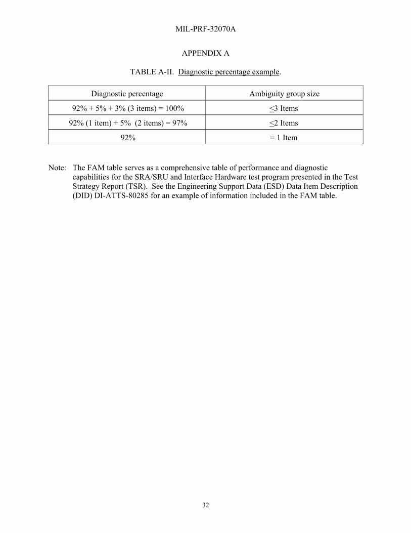
MIL-PRF-32070A
32
APPENDIX A
TABLE A-II. Diagnostic percentage example.
Diagnostic percentage Ambiguity group size
92% + 5% + 3% (3 items) = 100% <3 Items
92% (1 item) + 5% (2 items) = 97% <2 Items
92% = 1 Item
Note: The FAM table serves as a comprehensive table of performance and diagnostic
capabilities for the SRA/SRU and Interface Hardware test program presented in the Test Strategy Report (TSR). See the Engineering Support Data (ESD) Data Item Description (DID) DI-ATTS-80285 for an example of information included in the FAM table.
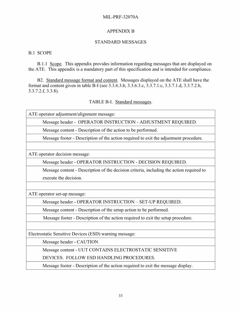
MIL-PRF-32070A
33
APPENDIX B
STANDARD MESSAGES
B.1 SCOPE B.1.1 Scope. This appendix provides information regarding messages that are displayed on the ATE. This appendix is a mandatory part of this specification and is intended for compliance. B2. Standard message format and content. Messages displayed on the ATE shall have the format and content given in table B-I (see 3.3.6.3.b, 3.3.6.3.c, 3.3.7.1.c, 3.3.7.1.d, 3.3.7.2.b, 3.3.7.2.f, 3.3.8).
TABLE B-I. Standard messages.
ATE operator adjustment/alignment message:
Message header - OPERATOR INSTRUCTION - ADJUSTMENT REQUIRED.
Message content - Description of the action to be performed.
Message footer - Description of the action required to exit the adjustment procedure.
ATE operator decision message:
Message header - OPERATOR INSTRUCTION - DECISION REQUIRED.
Message content - Description of the decision criteria, including the action required to
execute the decision.
ATE operator set-up message:
Message header - OPERATOR INSTRUCTION – SET-UP REQUIRED.
Message content - Description of the setup action to be performed.
Message footer - Description of the action required to exit the setup procedure.
Electrostatic Sensitive Devices (ESD) warning message:
Message header - CAUTION
Message content - UUT CONTAINS ELECTROSTATIC SENSITIVE
DEVICES. FOLLOW ESD HANDLING PROCEDURES.
Message footer - Description of the action required to exit the message display.

MIL-PRF-32070A
34
APPENDIX B
Table B-I. Standard messages - Continued.
Power on message (less than 30 volts):
Message header - NOTE.
Message content- (actual voltage value) VOLTS PRESENT
Message footer - Description of the action required to exit the message display
Power on warning message (greater than 30 volts and less than 500 volts):
Message header - WARNING.
Message content - (actual voltage value) VOLTS PRESENT
Message footer - Description of the action required to exit the message display.
Power on danger message (greater than 500 volts):
Message header - DANGER
Message content - (actual voltage value) VOLTS PRESENT
Message footer - Description of the action required to exit the message display.
Power off message:
Message header - UUT POWER OFF.
Message content - ALL POWER HAS BEEN REMOVED.
Message footer - Description of the action required to exit the message display.
UUT pass end of program message:
Message header - END OF PROGRAM - UUT GOOD.
Message content - UUT HAS PASSED ALL PERFORMANCE TESTS.
Message footer - Description of the action required to exit the message display.
UUT failed end of program message:
Message header - END OF PROGRAM - UUT FAULTY.
Message content - UUT DID NOT COMPLETE ALL PERFORMANCE TESTS.
Message footer - Description of the action required to exit the message display.
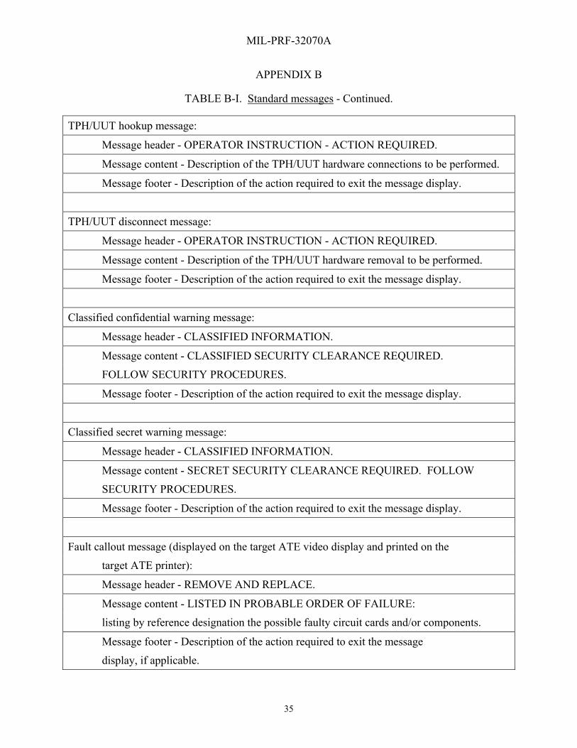
MIL-PRF-32070A
35
APPENDIX B
TABLE B-I. Standard messages - Continued.
TPH/UUT hookup message:
Message header - OPERATOR INSTRUCTION - ACTION REQUIRED.
Message content - Description of the TPH/UUT hardware connections to be performed.
Message footer - Description of the action required to exit the message display.
TPH/UUT disconnect message:
Message header - OPERATOR INSTRUCTION - ACTION REQUIRED.
Message content - Description of the TPH/UUT hardware removal to be performed.
Message footer - Description of the action required to exit the message display.
Classified confidential warning message:
Message header - CLASSIFIED INFORMATION.
Message content - CLASSIFIED SECURITY CLEARANCE REQUIRED.
FOLLOW SECURITY PROCEDURES.
Message footer - Description of the action required to exit the message display.
Classified secret warning message:
Message header - CLASSIFIED INFORMATION.
Message content - SECRET SECURITY CLEARANCE REQUIRED. FOLLOW
SECURITY PROCEDURES.
Message footer - Description of the action required to exit the message display.
Fault callout message (displayed on the target ATE video display and printed on the
target ATE printer):
Message header - REMOVE AND REPLACE.
Message content - LISTED IN PROBABLE ORDER OF FAILURE:
listing by reference designation the possible faulty circuit cards and/or components.
Message footer - Description of the action required to exit the message
display, if applicable.
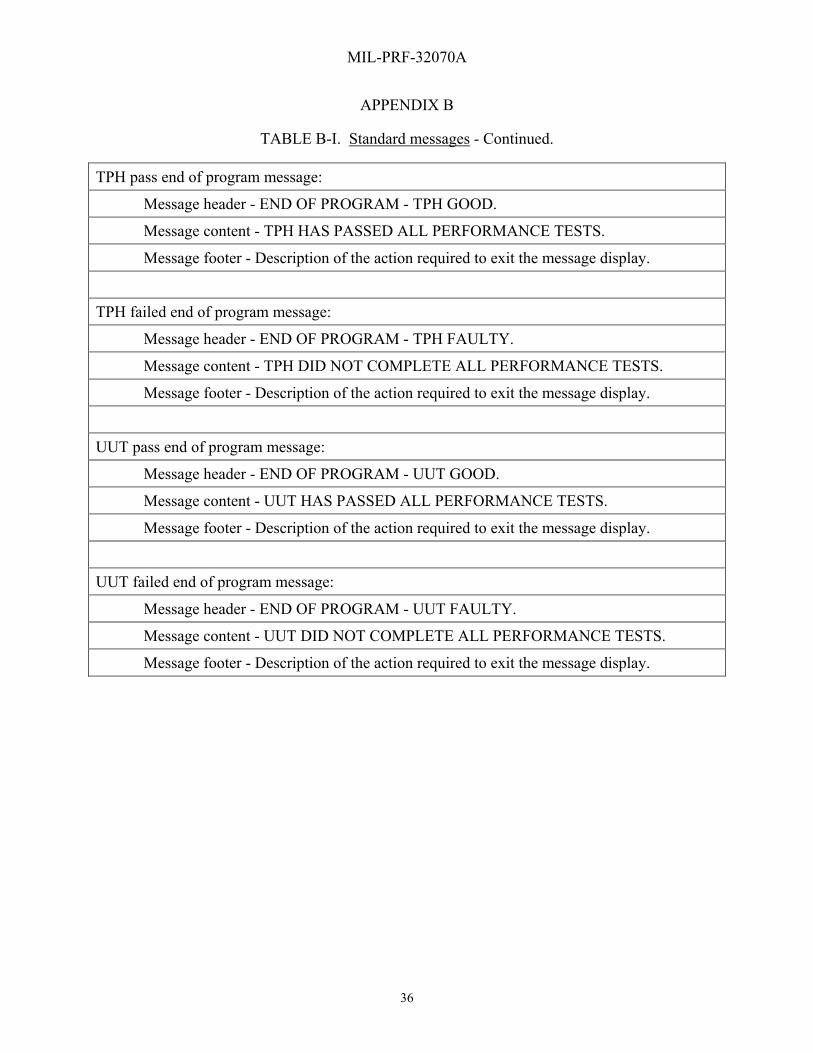
MIL-PRF-32070A
36
APPENDIX B
TABLE B-I. Standard messages - Continued.
TPH pass end of program message:
Message header - END OF PROGRAM - TPH GOOD.
Message content - TPH HAS PASSED ALL PERFORMANCE TESTS.
Message footer - Description of the action required to exit the message display.
TPH failed end of program message:
Message header - END OF PROGRAM - TPH FAULTY.
Message content - TPH DID NOT COMPLETE ALL PERFORMANCE TESTS.
Message footer - Description of the action required to exit the message display.
UUT pass end of program message:
Message header - END OF PROGRAM - UUT GOOD.
Message content - UUT HAS PASSED ALL PERFORMANCE TESTS.
Message footer - Description of the action required to exit the message display.
UUT failed end of program message:
Message header - END OF PROGRAM - UUT FAULTY.
Message content - UUT DID NOT COMPLETE ALL PERFORMANCE TESTS.
Message footer - Description of the action required to exit the message display.

MIL-PRF-32070A
37
Custodians: Preparing activity: Army – AR Navy – AS Navy – AS (Project ATTS-2011-001) Air Force – 70 Review activities: Army – AV Navy – MC Air Force – 10, 13, 71, 84 NOTE: The activities listed above were interested in this document as of the date of this document. Since organizations and responsibilities can change, you should verify the currency of the information above using the ASSIST Online data base at https://assist.daps.dla.mil.