performance | technology | innovation
TRANSCRIPT
PERFORMANCE | TECHNOLOGY | INNOVATION
BORETS U.S. INC.
HORIZONTAL PUMPING SYSTEM
What is HPS?HPS classification, Pumps, Stages, Impellers, Curves/Performance, Components
Why use HPS?Delivery/Cost/Modular, Radial Loads, Comparison vs. Traditional Pumps
What are common HPS Applications/Installation?Produced Water/Injection, Lean Amine, Crude Oil, NGL, Liquid CO2, etc.
Horizontal Pumping System
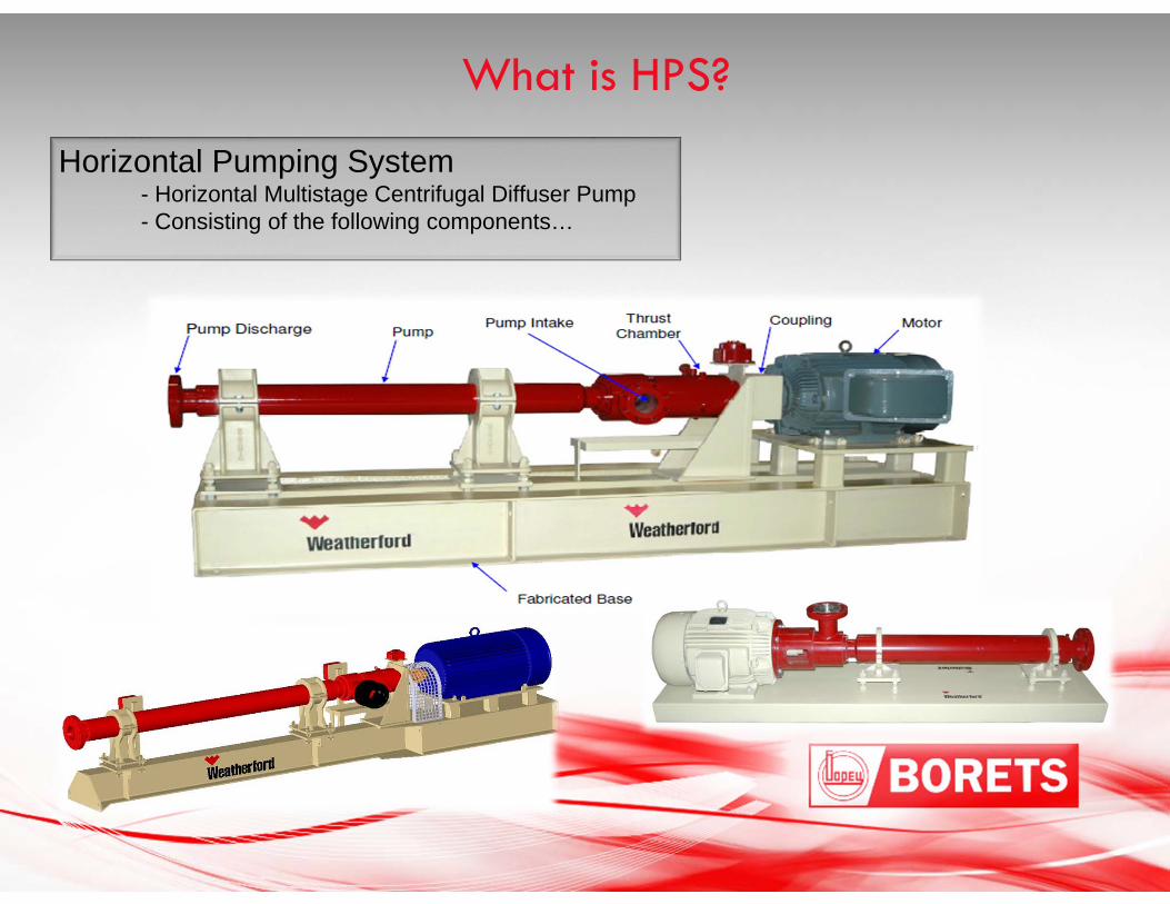
Horizontal Pumping System- Horizontal Multistage Centrifugal Diffuser Pump- Consisting of the following components…
What is HPS?
*
* * ** *
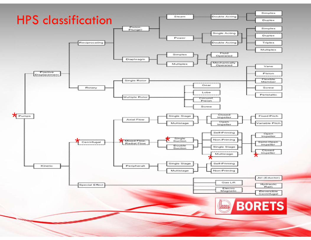
HPS classification
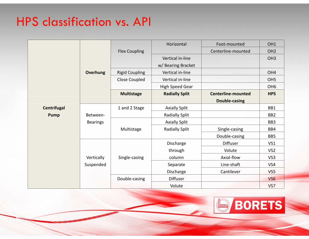
HPS classification vs. APIHorizontal Foot‐mounted OH1
Flex Coupling Centerline‐mounted OH2Vertical in‐line OH3
w/ Bearing BracketOverhung Rigid Coupling Vertical in‐line OH4
Close Coupled Vertical in‐line OH5High Speed Gear OH6
Multistage Radially Split Centerline‐mounted HPSDouble‐casing
Centrifugal 1 and 2 Stage Axially Split BB1Pump Between‐ Radially Split BB2
Bearings Axially Split BB3Multistage Radially Split Single‐casing BB4
Double‐casing BB5Discharge Diffuser VS1through Volute VS2
Vertically Single‐casing column Axial‐flow VS3Suspended Separate Line‐shaft VS4
Discharge Cantilever VS5Double‐casing Diffuser VS6
Volute VS7
Pumps
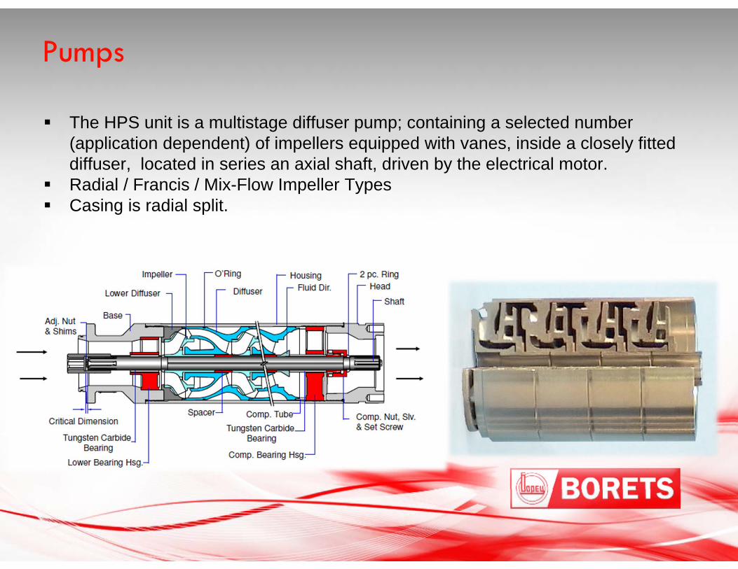
The HPS unit is a multistage diffuser pump; containing a selected number (application dependent) of impellers equipped with vanes, inside a closely fitted diffuser, located in series an axial shaft, driven by the electrical motor.
Radial / Francis / Mix-Flow Impeller Types Casing is radial split.
Stages
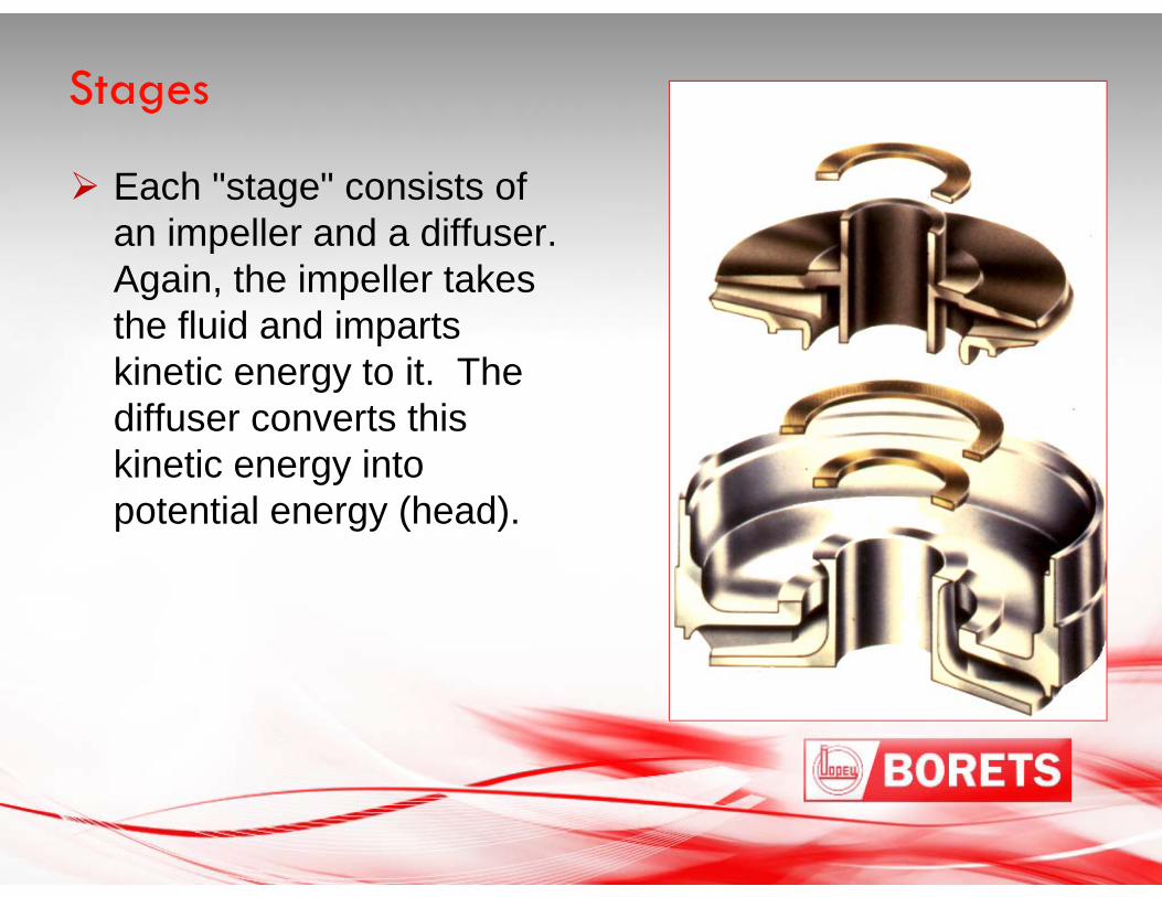
Each "stage" consists of an impeller and a diffuser. Again, the impeller takes the fluid and imparts kinetic energy to it. The diffuser converts this kinetic energy into potential energy (head).
Operation
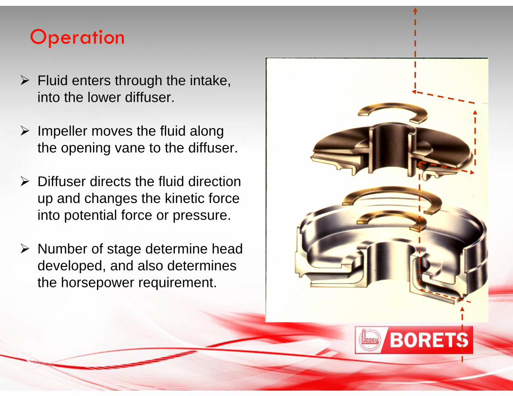
Fluid enters through the intake, into the lower diffuser.
Impeller moves the fluid along the opening vane to the diffuser.
Diffuser directs the fluid direction up and changes the kinetic force into potential force or pressure.
Number of stage determine head developed, and also determines the horsepower requirement.
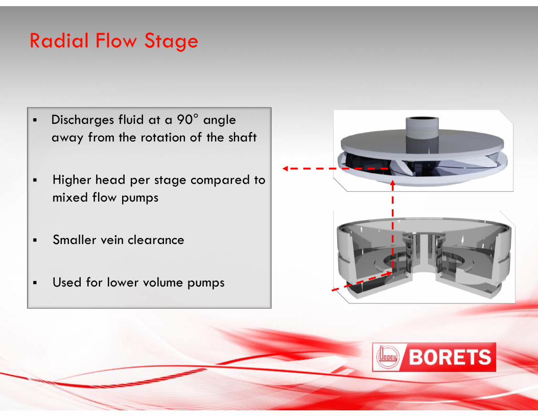
Radial Flow Stage
Discharges fluid at a 90° angle away from the rotation of the shaft
Higher head per stage compared to mixed flow pumps
Smaller vein clearance
Used for lower volume pumps
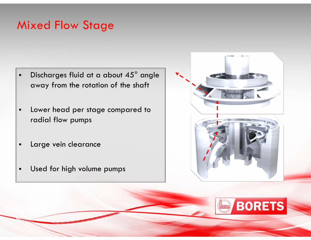
Mixed Flow Stage
Discharges fluid at a about 45° angle away from the rotation of the shaft
Lower head per stage compared to radial flow pumps
Large vein clearance
Used for high volume pumps
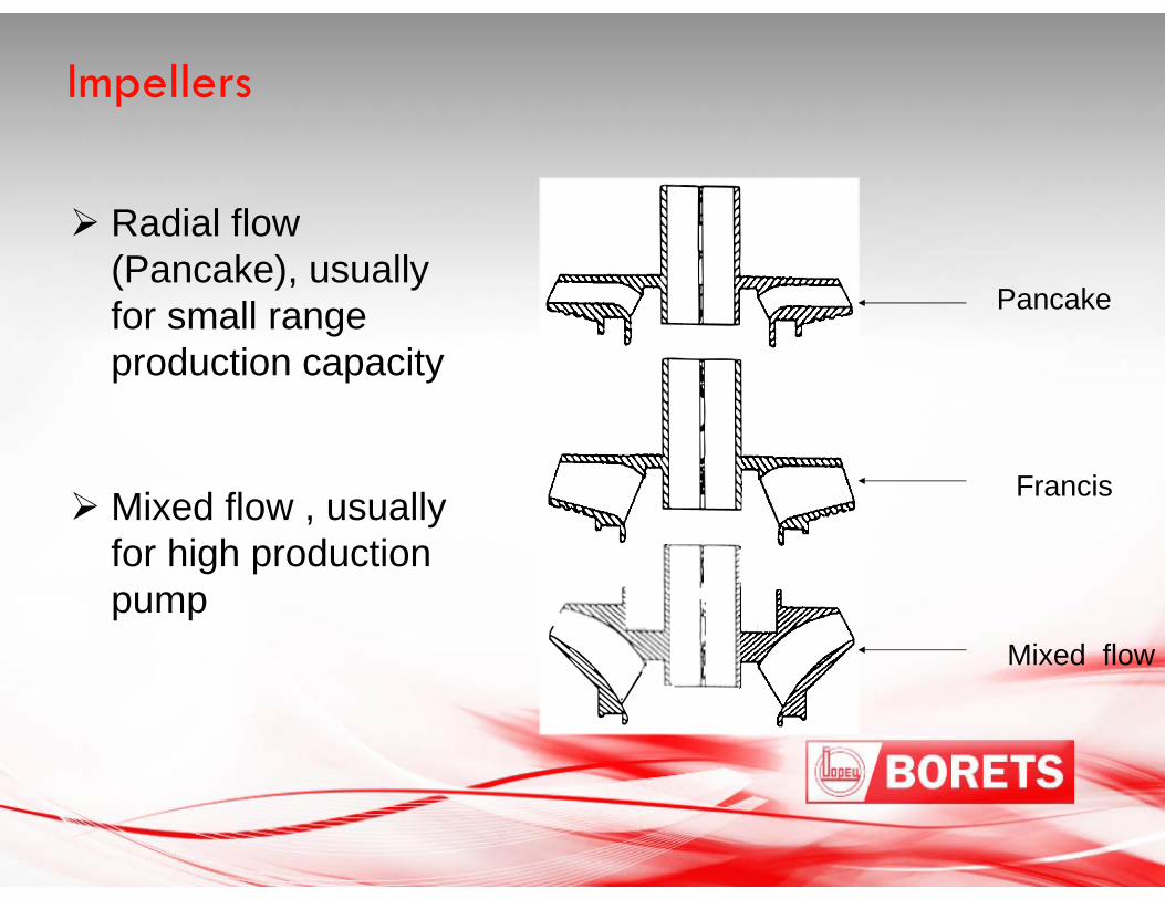
Impellers
Radial flow (Pancake), usually for small range production capacity
Mixed flow , usually for high production pump
Pancake
Francis
Mixed flow
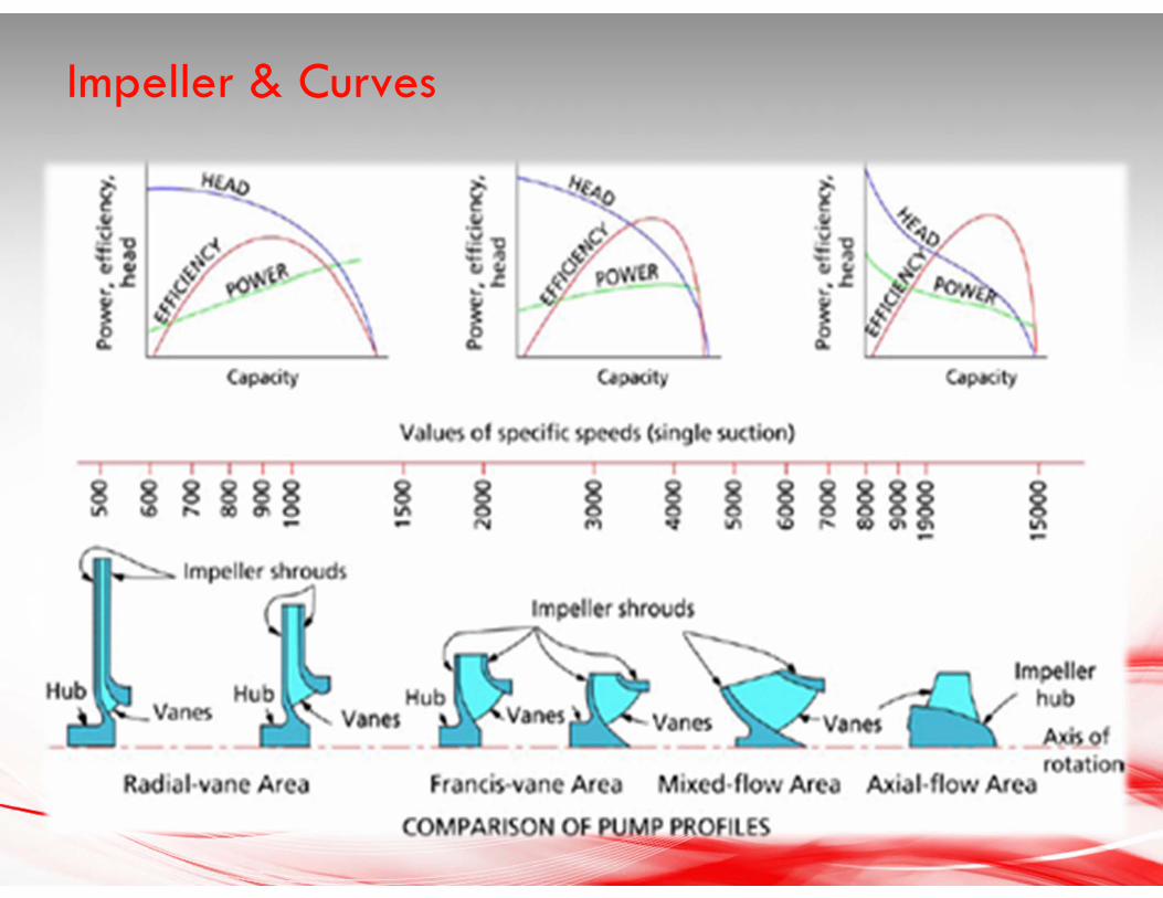
Impeller & Curves
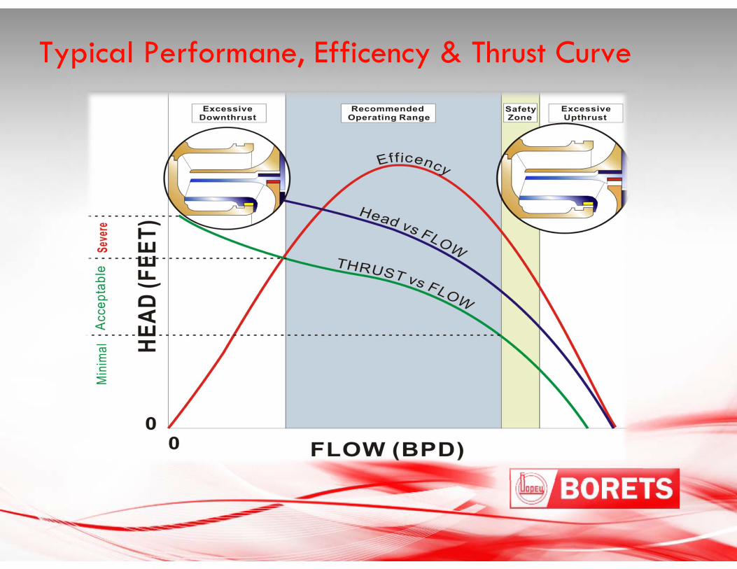
Typical Performane, Efficency & Thrust Curve
Pumps come in two basic varieties:
“Floater" construction - each impeller is free to move side to side on the shaft as it wants to so it is said to "float" on the shaft.
“Compression" construction - every impeller is fixed to the shaft rigidly so that it cannot move without the shaft moving. All the impellers are "compressed" together to make one rigid rotating assembly.
Pumps
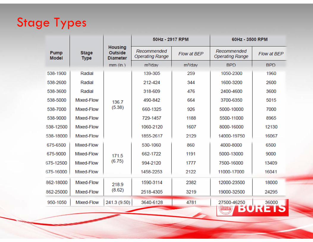
Stage Types

Thrust Chamber & Intake
Modular Design
Minimal Moving Parts
Largest Thrust Bearings 7315
Oil Flood Lubrication
2 bearing = 4000# thrust
3 bearing = 6000# thrust
4 bearing = 12000# thrust
Standard 316 S/S or Carbon Steel Construction
Standard ANSI B16.5 Class Flange Ratings
- 150/300/600/900/1500/2500 lb
Suction Flange Locations Rotates
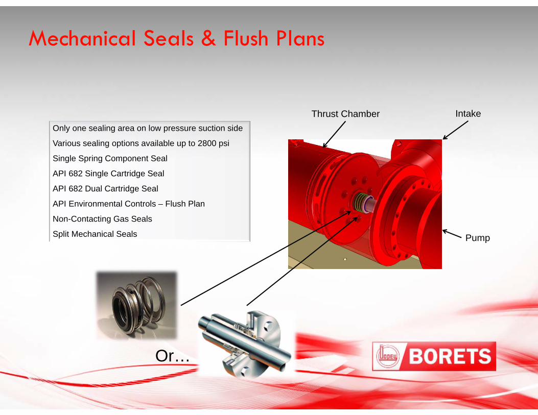
Mechanical Seals & Flush Plans
Only one sealing area on low pressure suction side
Various sealing options available up to 2800 psi
Single Spring Component Seal
API 682 Single Cartridge Seal
API 682 Dual Cartridge Seal
API Environmental Controls – Flush Plan
Non-Contacting Gas Seals
Split Mechanical Seals
Thrust Chamber Intake
Pump
Or…
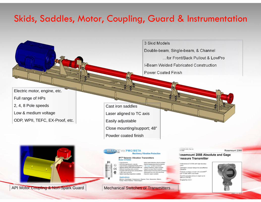
Skids, Saddles, Motor, Coupling, Guard & Instrumentation
3 Skid Models
Double-beam, Single-beam, & Channel
…for Front/Back Pullout & LowPro
I-Beam Welded Fabricated Construction
Power Coated Finish
Mechanical Switches or Transmitters…
Cast iron saddles
Laser aligned to TC axis
Easily adjustable
Close mounting/support; 48”
Powder coated finish
Electric motor, engine, etc.
Full range of HPs
2, 4, 8 Pole speeds
Low & medium voltage
ODP, WPII, TEFC, EX-Proof, etc.
API Motor Coupling & Non-Spark Guard
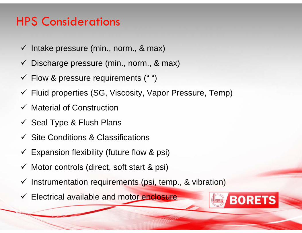
Intake pressure (min., norm., & max)
Discharge pressure (min., norm., & max)
Flow & pressure requirements (“ “)
Fluid properties (SG, Viscosity, Vapor Pressure, Temp)
Material of Construction
Seal Type & Flush Plans
Site Conditions & Classifications
Expansion flexibility (future flow & psi)
Motor controls (direct, soft start & psi)
Instrumentation requirements (psi, temp., & vibration)
Electrical available and motor enclosure
HPS Considerations

Quick Delivery - 8 to 12 Weeks
Low Capital Cost
Extended Run LifeIncreased Reliability & MTBFLow Maintenance
High Quality Standards
Modular Design Easy replacement & minimal “down-time”Easy to Re-rate in the futureMinimal Spare Parts Inventory
Environmentally Friendly
Low Life Cycle Cost
Why use HPS?
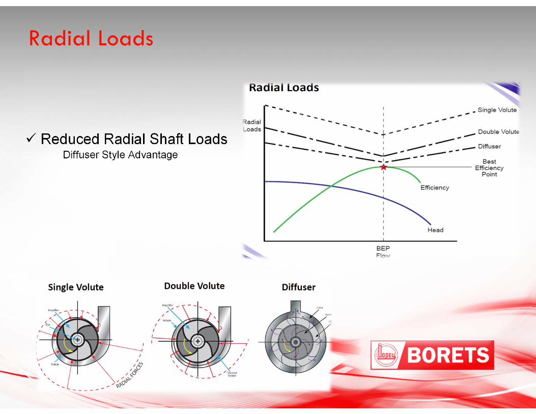
Reduced Radial Shaft Loads Diffuser Style Advantage
Radial Loads
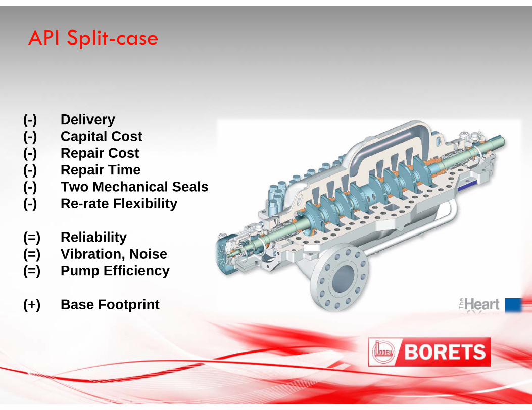
(-) Delivery(-) Capital Cost(-) Repair Cost(-) Repair Time(-) Two Mechanical Seals(-) Re-rate Flexibility
(=) Reliability(=) Vibration, Noise(=) Pump Efficiency
(+) Base Footprint
API Split-case
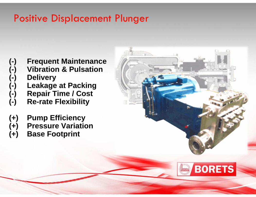
(-) Frequent Maintenance(-) Vibration & Pulsation(-) Delivery(-) Leakage at Packing(-) Repair Time / Cost(-) Re-rate Flexibility
(+) Pump Efficiency(+) Pressure Variation(+) Base Footprint
Positive Displacement Plunger
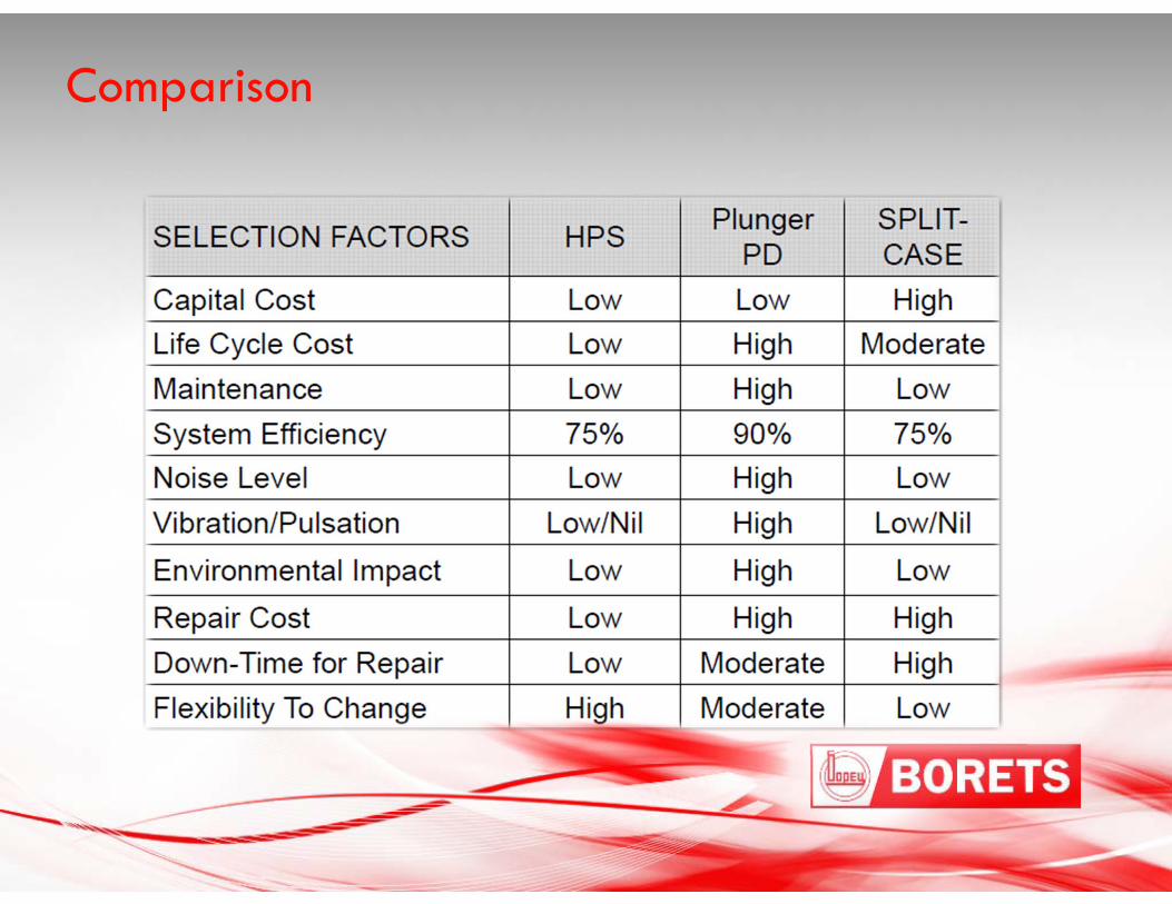
Comparison
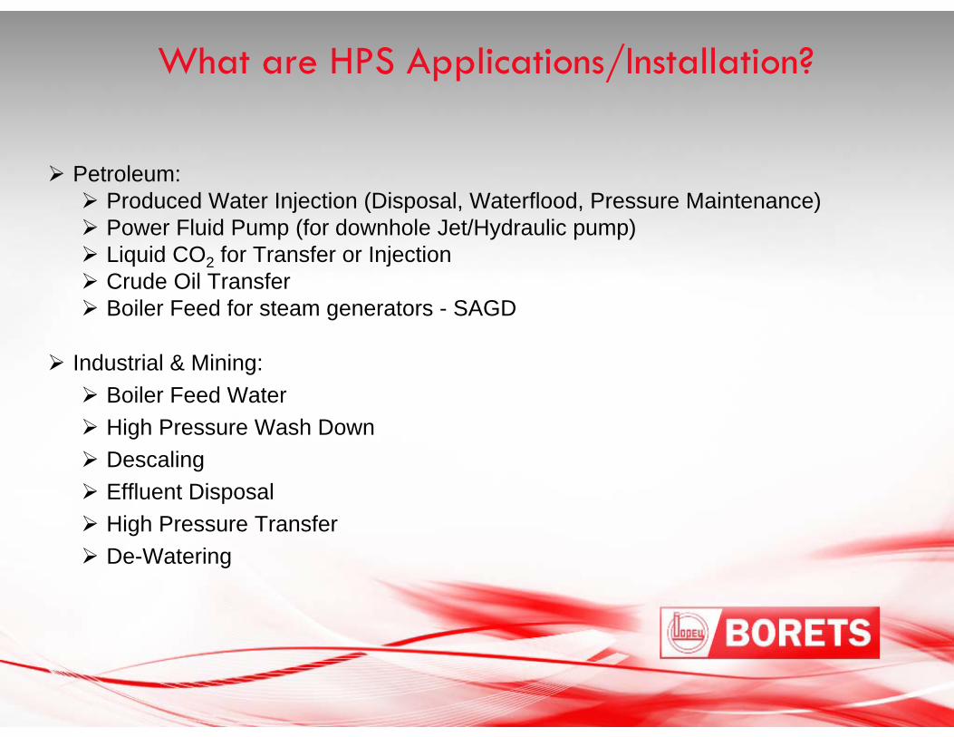
Petroleum: Produced Water Injection (Disposal, Waterflood, Pressure Maintenance) Power Fluid Pump (for downhole Jet/Hydraulic pump) Liquid CO2 for Transfer or Injection Crude Oil Transfer Boiler Feed for steam generators - SAGD
Industrial & Mining: Boiler Feed Water High Pressure Wash Down Descaling Effluent Disposal High Pressure Transfer De-Watering
What are HPS Applications/Installation?
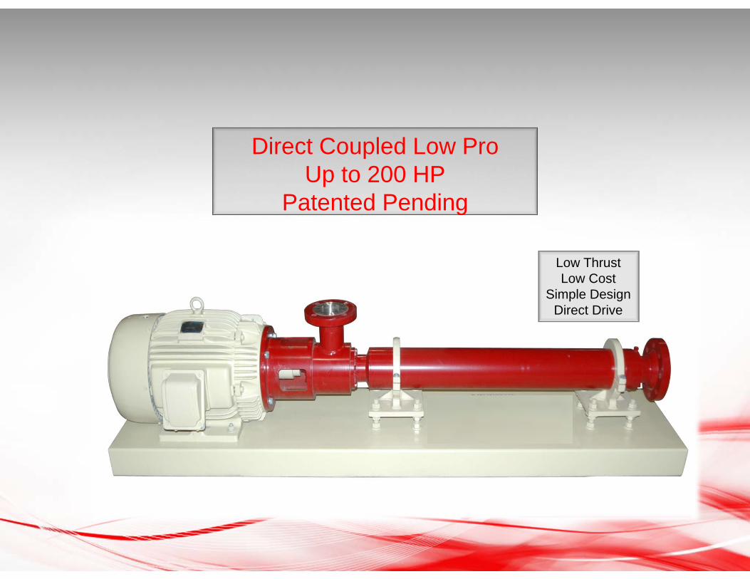
Direct Coupled Low ProUp to 200 HP
Patented Pending
Low ThrustLow Cost
Simple DesignDirect Drive
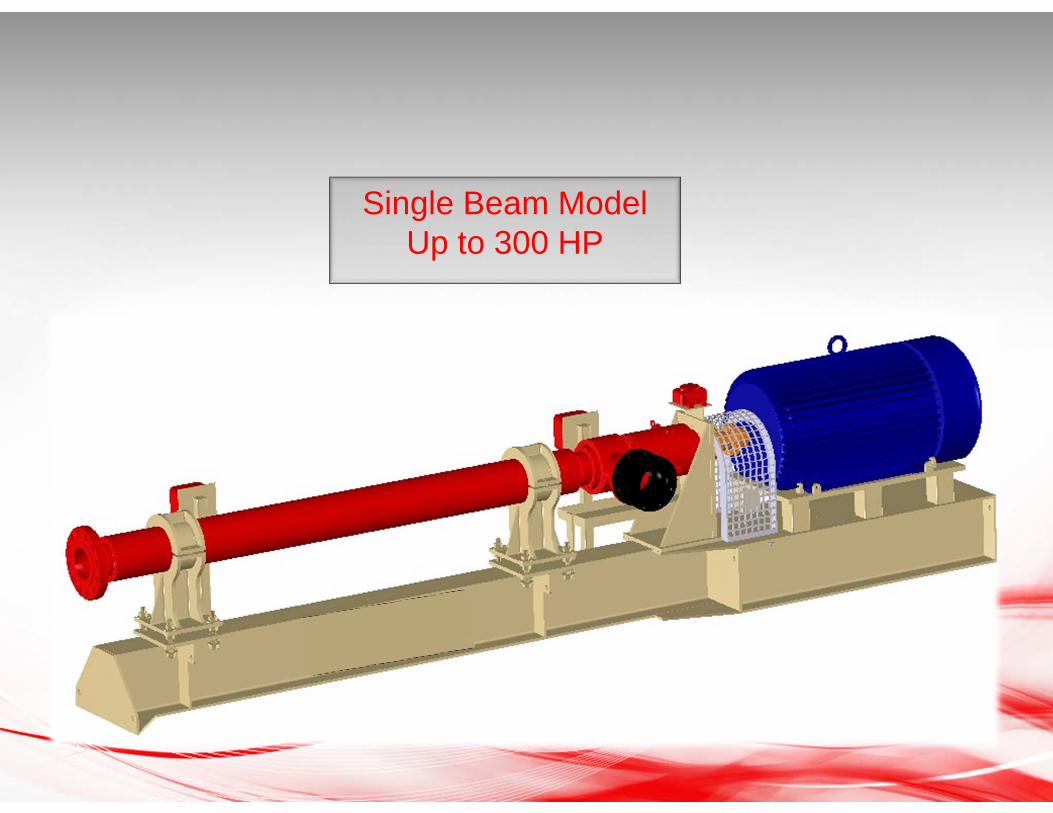
Single Beam ModelUp to 300 HP
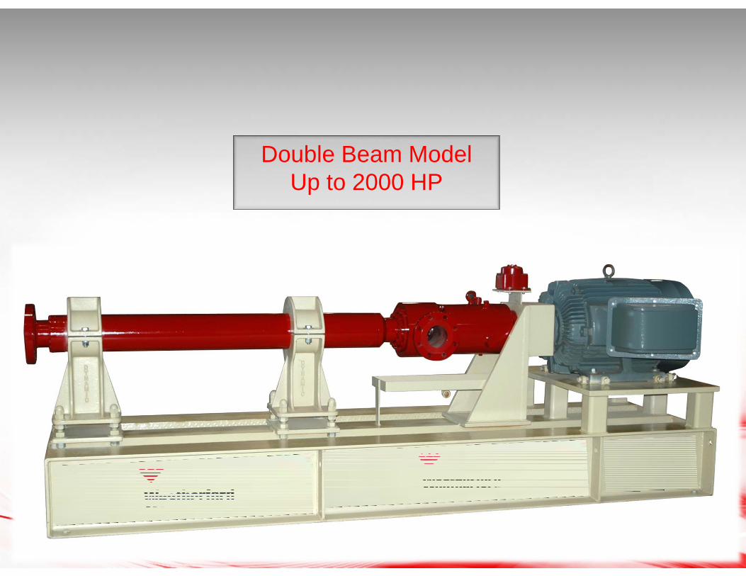
Double Beam ModelUp to 2000 HP
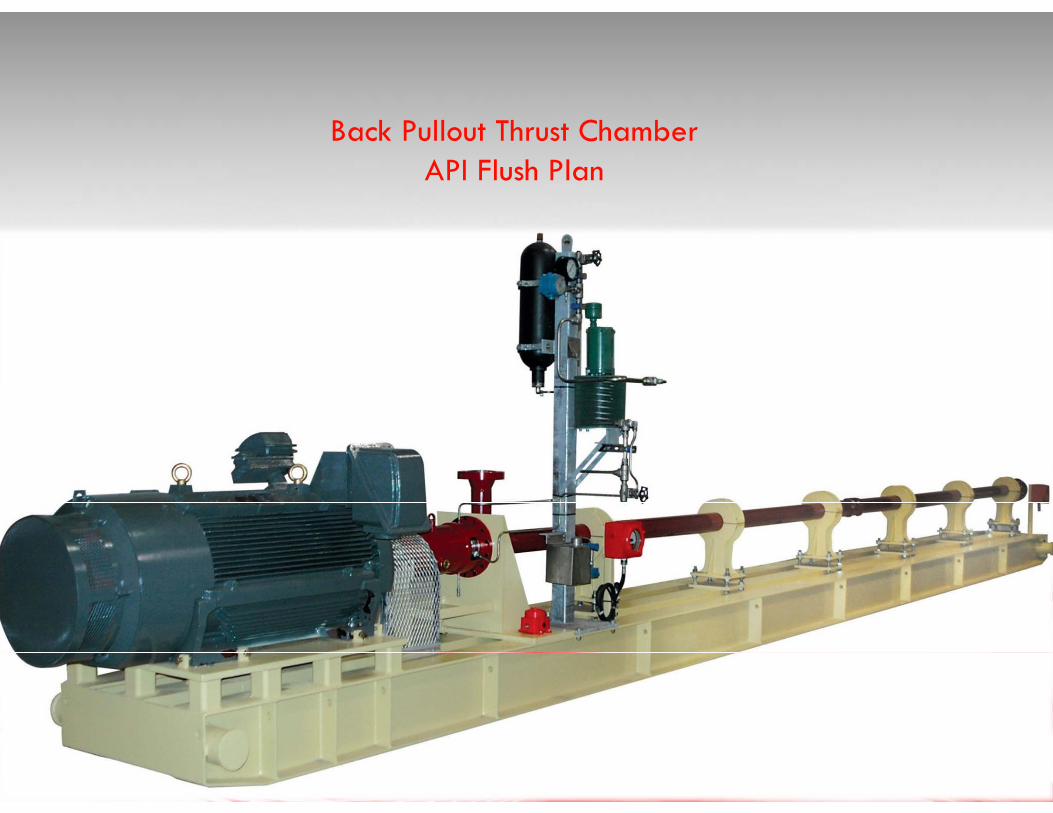
Back Pullout Thrust ChamberAPI Flush Plan
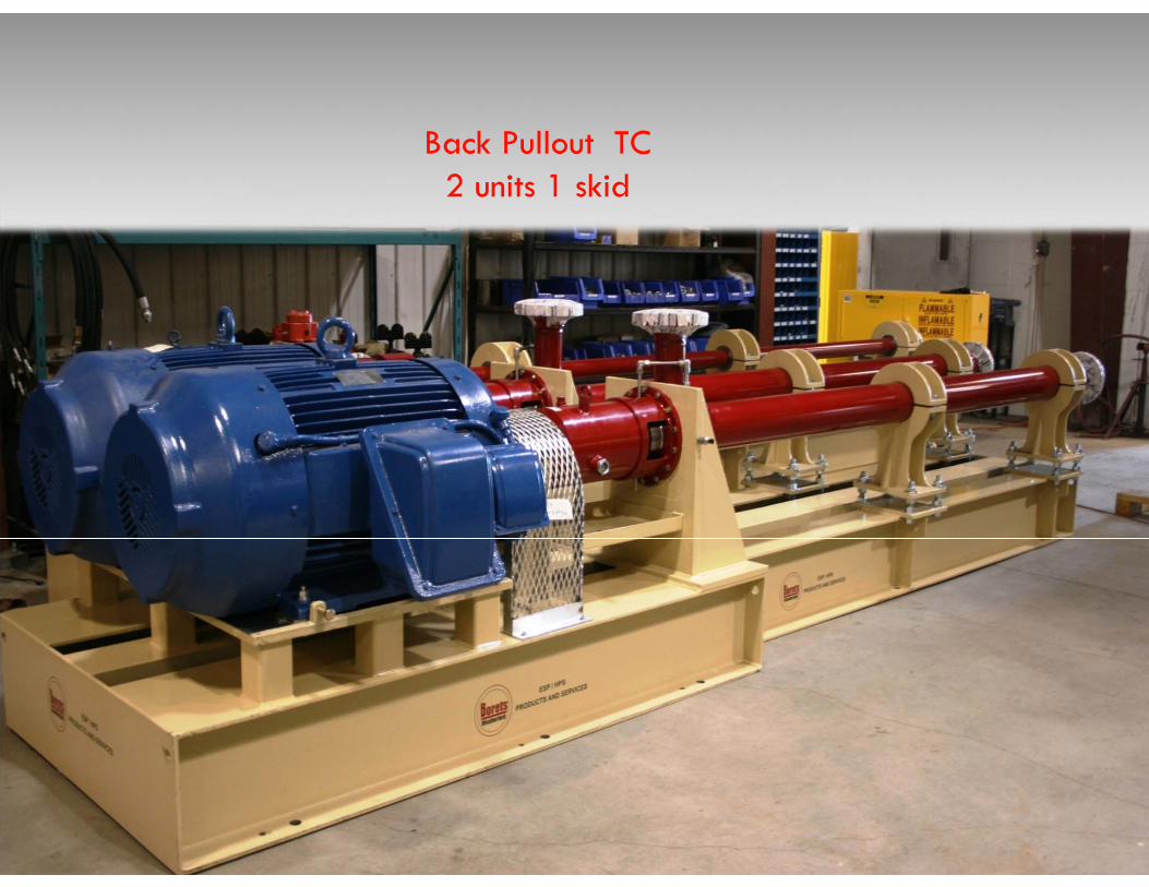
Back Pullout TC2 units 1 skid
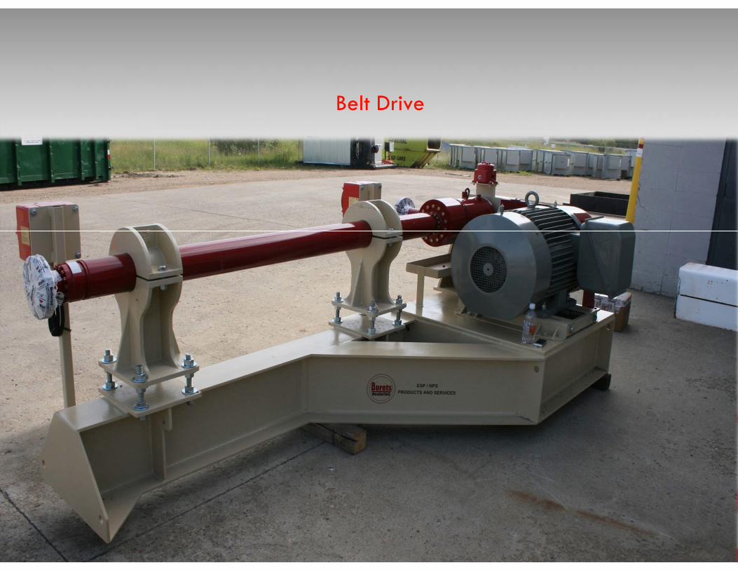
Belt Drive

Crude Oil Transfer – Texas, USA
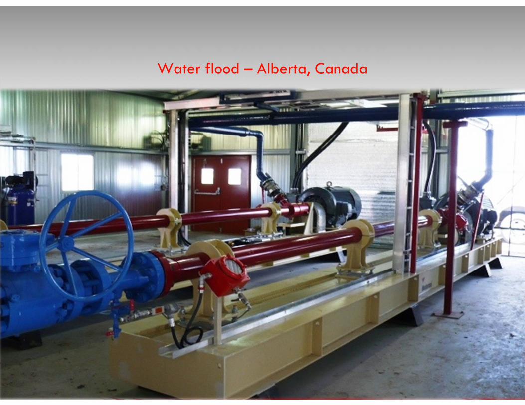
Water flood – Alberta, Canada
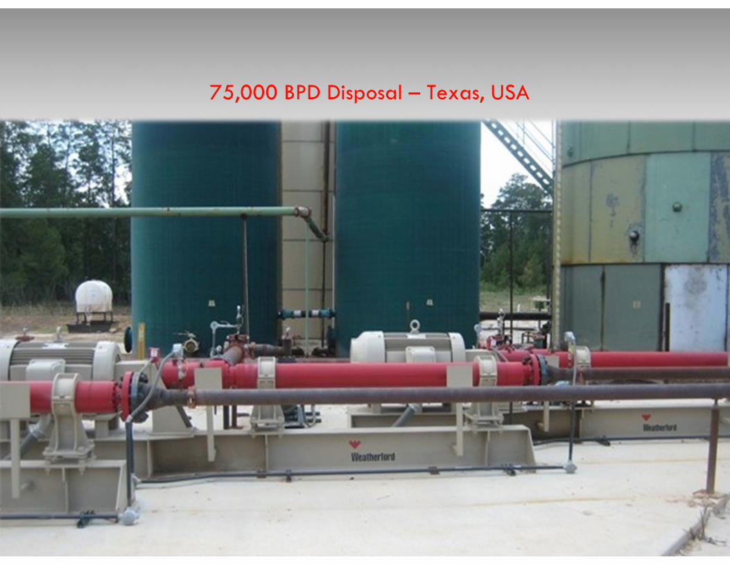
75,000 BPD Disposal – Texas, USA
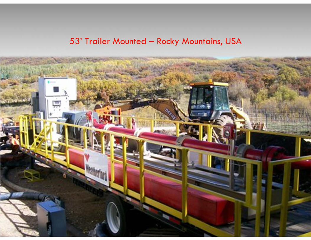
53’ Trailer Mounted – Rocky Mountains, USA
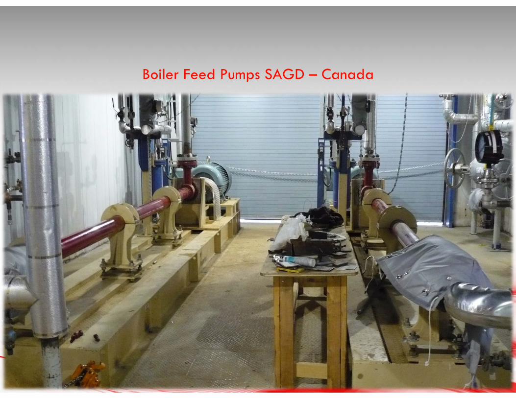
Boiler Feed Pumps SAGD – Canada
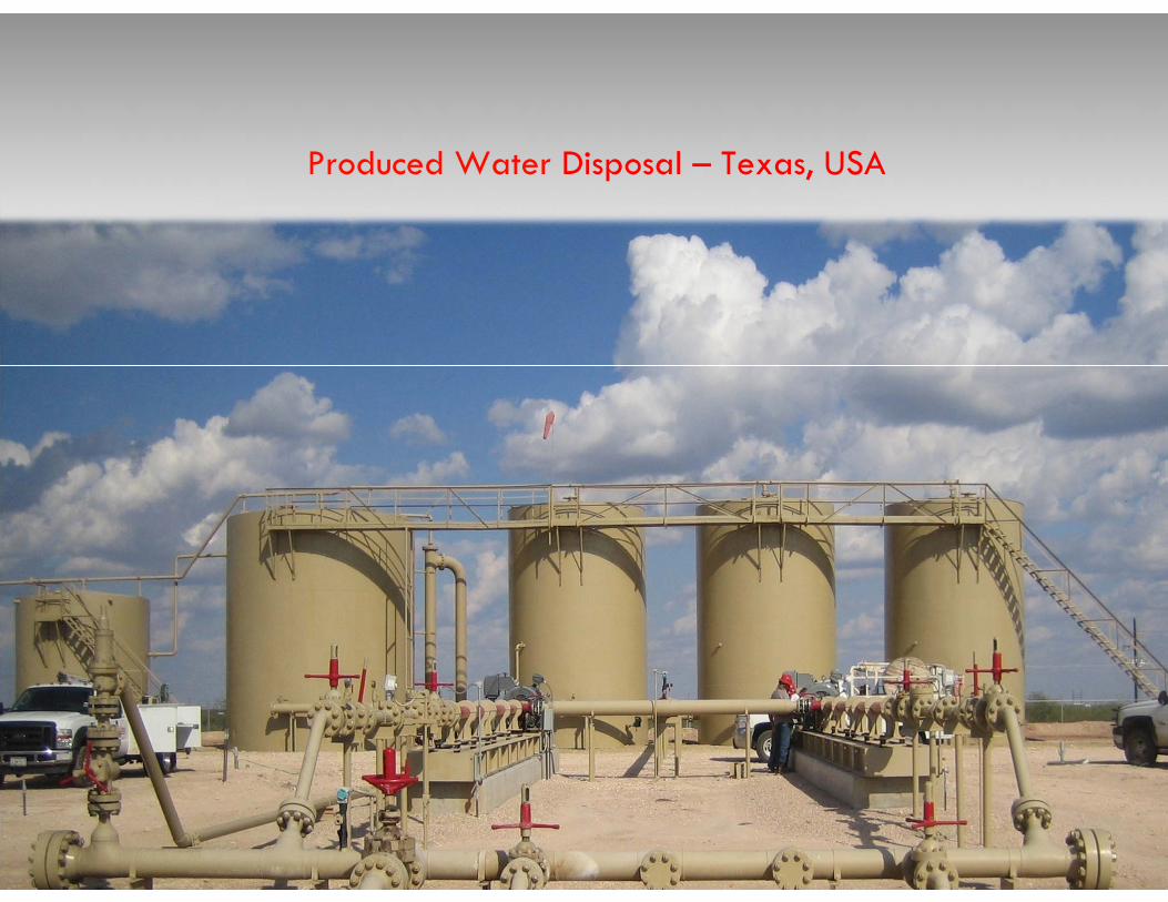
Produced Water Disposal – Texas, USA
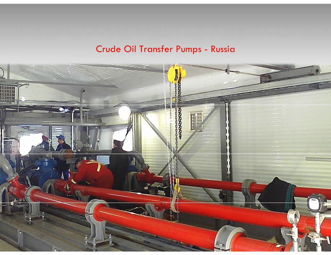
Crude Oil Transfer Pumps - Russia
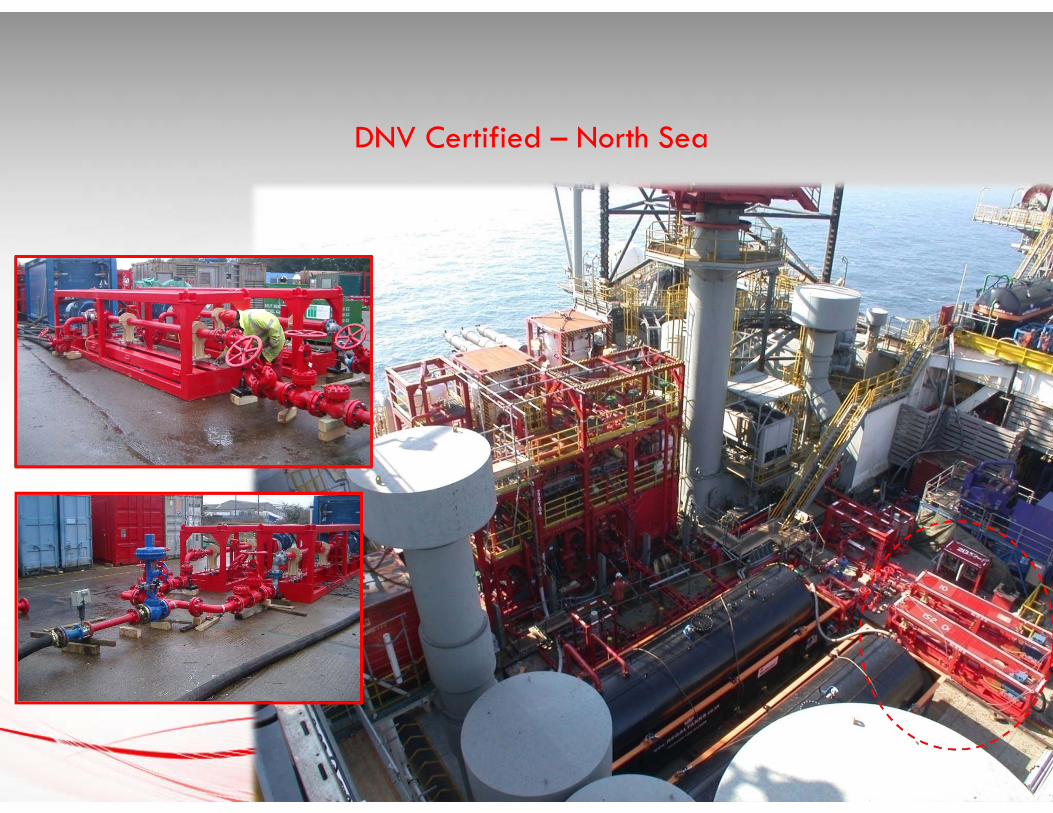
DNV Certified – North Sea
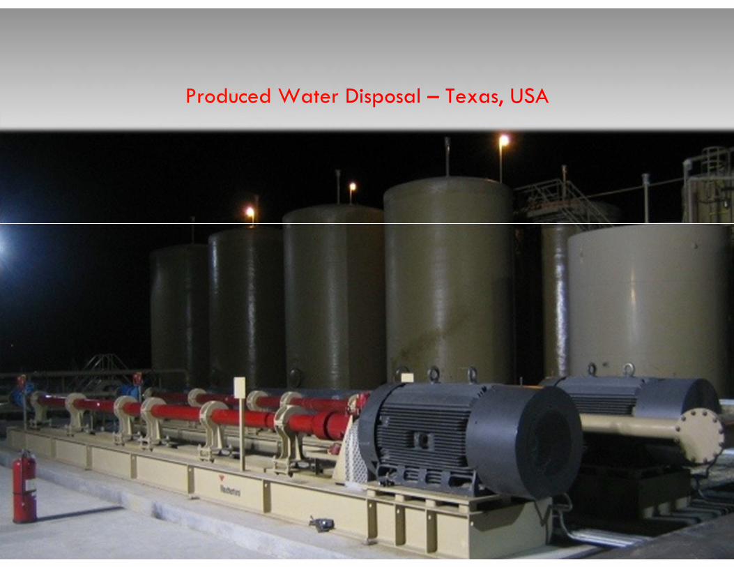
Produced Water Disposal – Texas, USA
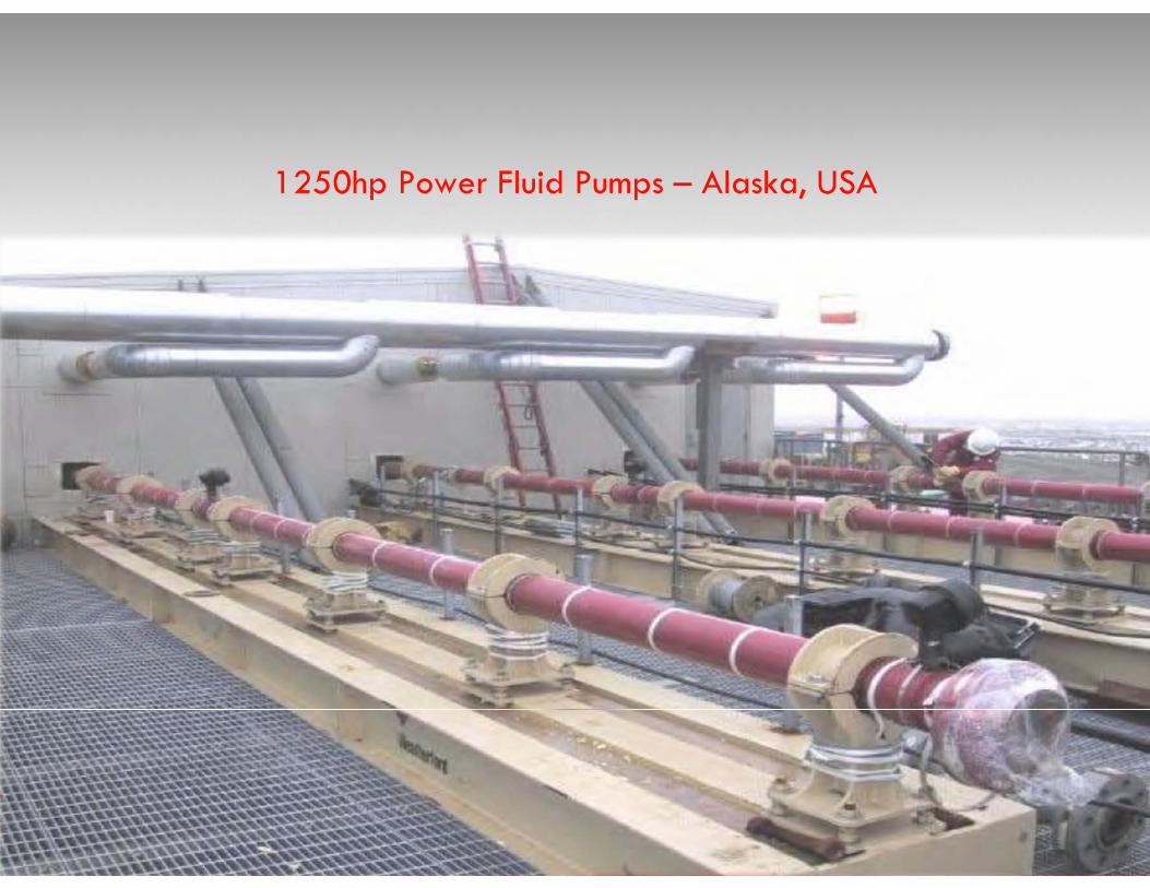
1250hp Power Fluid Pumps – Alaska, USA
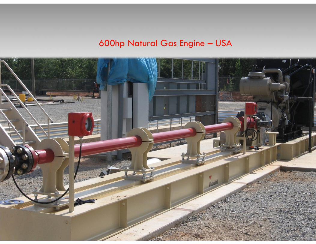
600hp Natural Gas Engine – USA
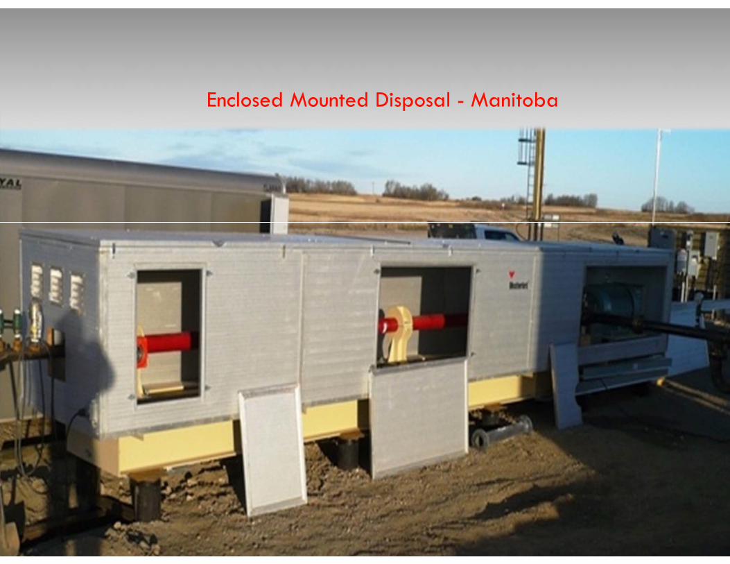
Enclosed Mounted Disposal - Manitoba
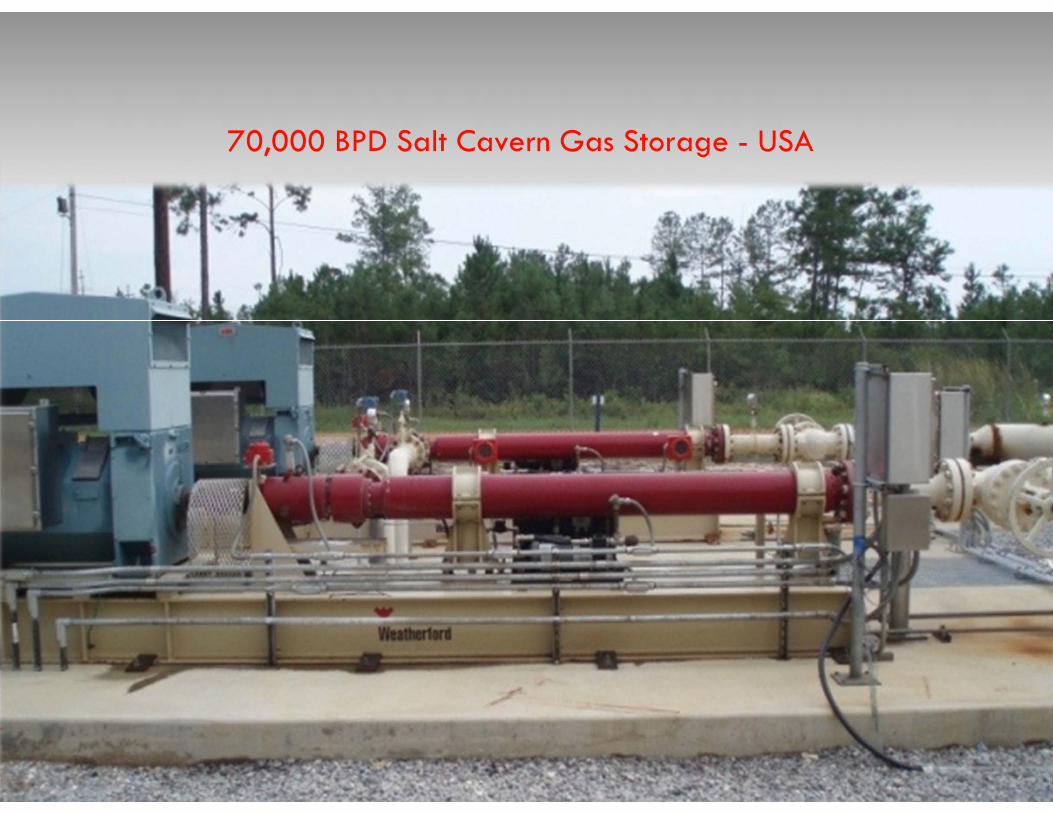
70,000 BPD Salt Cavern Gas Storage - USA

PERFORMANCE | TECHNOLOGY | INNOVATION&
CUSTOMER SERVICE
HORIZONTAL PUMPING SYSTEM
QUESTIONS?