permanent magnets for linear colliders
DESCRIPTION
Permanent Magnets for Linear Colliders. James T Volk Fermilab. People already working on Permanent magnets. LBNL Jose Alonso, Jin-Young Jung. SLAC Seung Rhee, Cherrill Spencer, Jim Spencer. SLAC Magnetic Measurement Group Scott Anderson, Zack Wolf. Fermilab Magnetic Measurement. - PowerPoint PPT PresentationTRANSCRIPT
James T Volk June 2002 1
f
Permanent Magnets forLinear Colliders
James T Volk
Fermilab
James T Volk June 2002 2
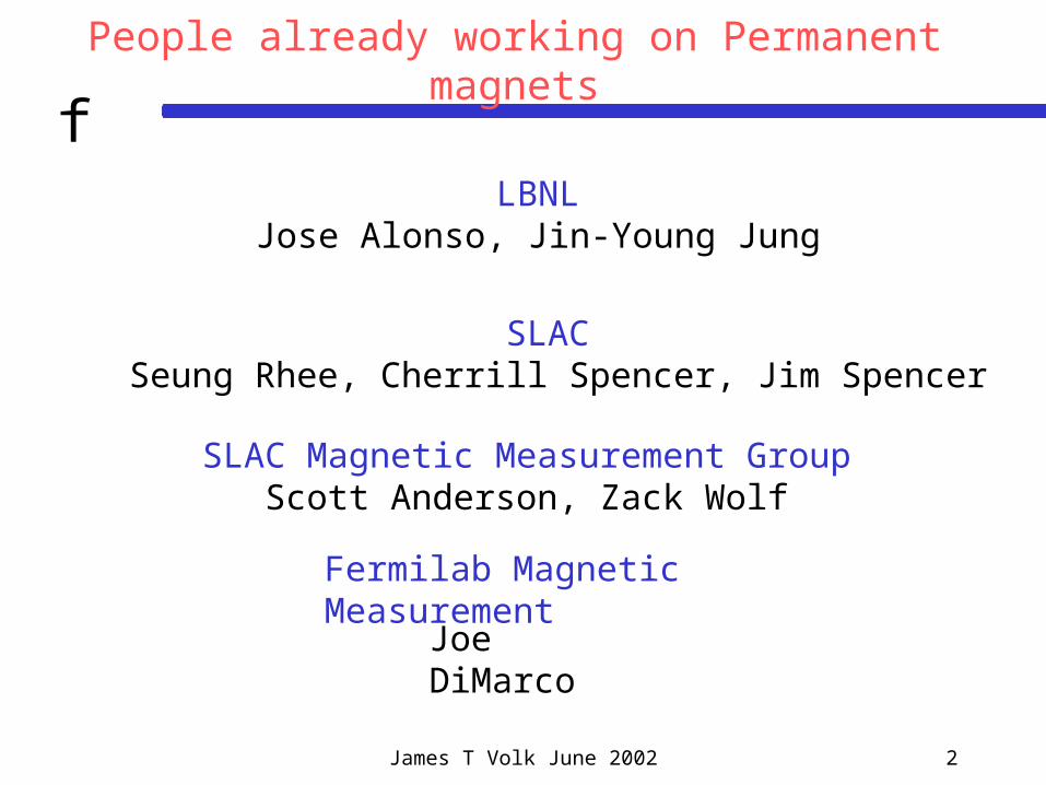
fPeople already working on Permanent magnets
SLAC Seung Rhee, Cherrill Spencer, Jim Spencer
SLAC Magnetic Measurement GroupScott Anderson, Zack Wolf
Fermilab Magnetic Measurement
Joe DiMarco
LBNLJose Alonso, Jin-Young Jung
James T Volk June 2002 3
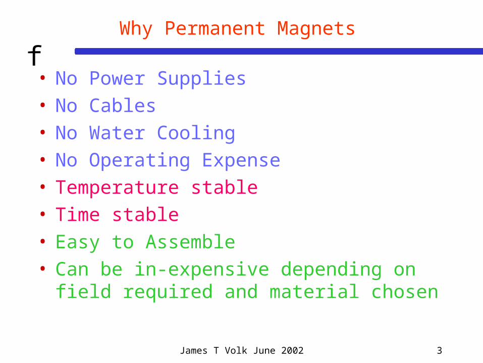
fWhy Permanent Magnets
• No Power Supplies• No Cables• No Water Cooling• No Operating Expense• Temperature stable• Time stable• Easy to Assemble• Can be in-expensive depending on field required
and material chosen

James T Volk June 2002 4
fWhere can they be used
• Fixed energy transport lines • Bending
• Focusing
• Injection or extraction
• Storage Rings• Final Focus near or inside of detectors• Quadrupoles in the NLC• Damping Rings
James T Volk June 2002 5
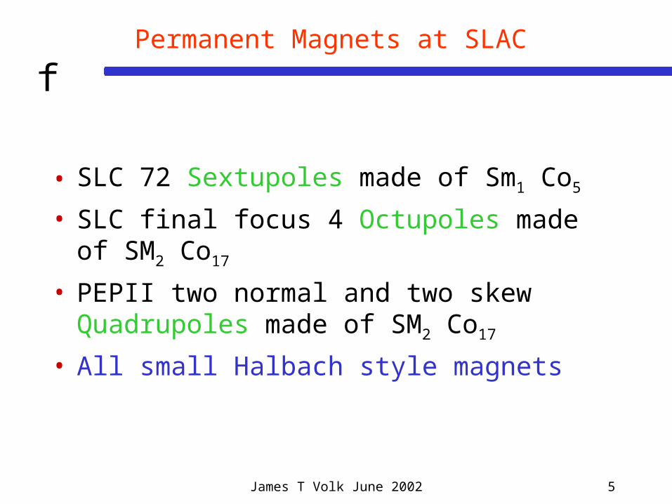
fPermanent Magnets at SLAC
• SLC 72 Sextupoles made of Sm1 Co5
• SLC final focus 4 Octupoles made of SM2 Co17
• PEPII two normal and two skew Quadrupoles made of SM2 Co17
• All small Halbach style magnets
James T Volk June 2002 6
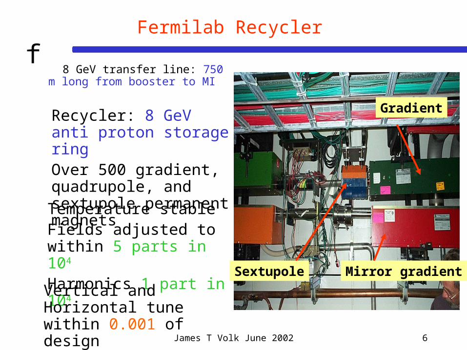
fFermilab Recycler
8 GeV transfer line: 750 m long from booster to MI
Gradient
Mirror gradientSextupole
Recycler: 8 GeV anti proton storage ring Over 500 gradient, quadrupole, and sextupole permanent magnets
Temperature stableFields adjusted to within 5 parts in 104 Harmonics 1 part in 104
Vertical and Horizontal tune within 0.001 of design

James T Volk June 2002 7
fRepresentative Dipole Technologies
0
0.2
0.4
0.6
0.8
1
1.2
1.4
1.6
0 100 200 300 400 500 600 700 800
Full gap [mm]
On
-ax
is f
ield
[T
]
NdFeB
Electromagnet
Ferrite
From Kem Robinson LBNL
James T Volk June 2002 8
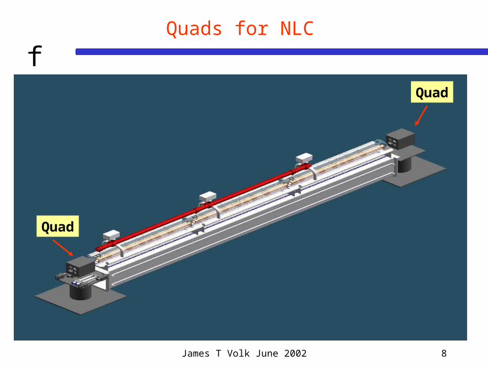
fQuads for NLC
Quad
Quad
James T Volk June 2002 9
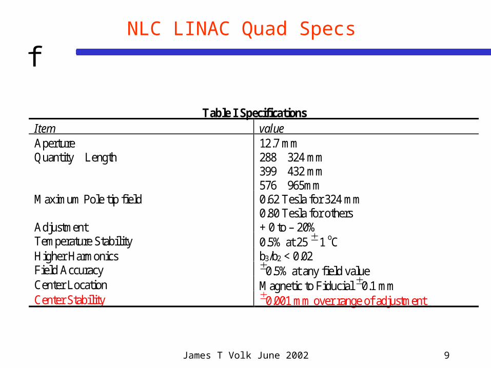
fNLC LINAC Quad Specs
Table I SpecificationsItem valueAperture 12.7 mmQuantity Length 288 324 mm
399 432 mm576 965mm
Maximum Pole tip field 0.62 Tesla for 324 mm0.80 Tesla for others
Adjustment + 0 to – 20%Temperature Stability 0.5% at 25 1 oCHigher Harmonics b3/b2 < 0.02Field Accuracy 0.5% at any field valueCenter Location Magnetic to Fiducial 0.1 mmCenter Stability 0.001 mm over range of adjustment

James T Volk June 2002 10
f
Wedge QuadRods rotate to adjust field
Pole Magnets
Tuning Rods
Wedge Magnets
Flux Return
Poles

James T Volk June 2002 11
fNLC adjustable quad on SSW stand
Quad
Stretched wire stages
James T Volk June 2002 12
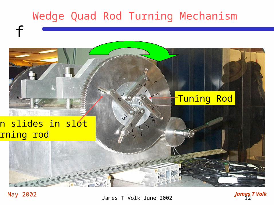
fWedge Quad Rod Turning Mechanism
Tuning Rod
May 2002 James T Volk
Pin slides in slot turning rod

James T Volk June 2002 13
fCenter shifts wedge quad
FWSQ001-6
-5.0
-4.0
-3.0
-2.0
-1.0
0.0
1.0
2.0
3.0
20.5 21.5 22.5 23.5 24.5 25.5
YGdl Tesla
y c
en
ter
mic
rom
ete
rs
1st pass
2nd pass
3rd pass
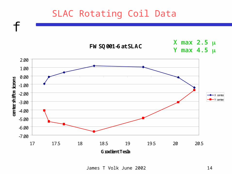
James T Volk June 2002 14
fSLAC Rotating Coil Data
FWSQ001-6 at SLAC
-7.00
-6.00
-5.00
-4.00
-3.00
-2.00
-1.00
0.00
1.00
2.00
17 17.5 18 18.5 19 19.5 20 20.5
Gradient Tesla
cen
ter
shif
t m
icro
ns
X center
Y center
X max 2.5 Y max 4.5
James T Volk June 2002 15
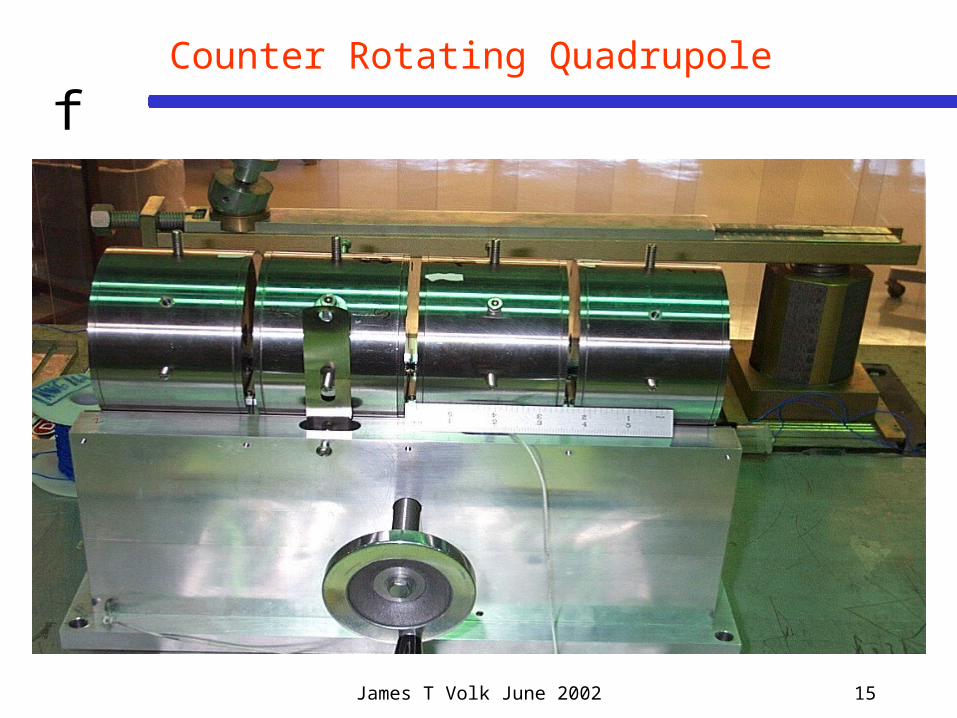
fCounter Rotating Quadrupole
James T Volk June 2002 16
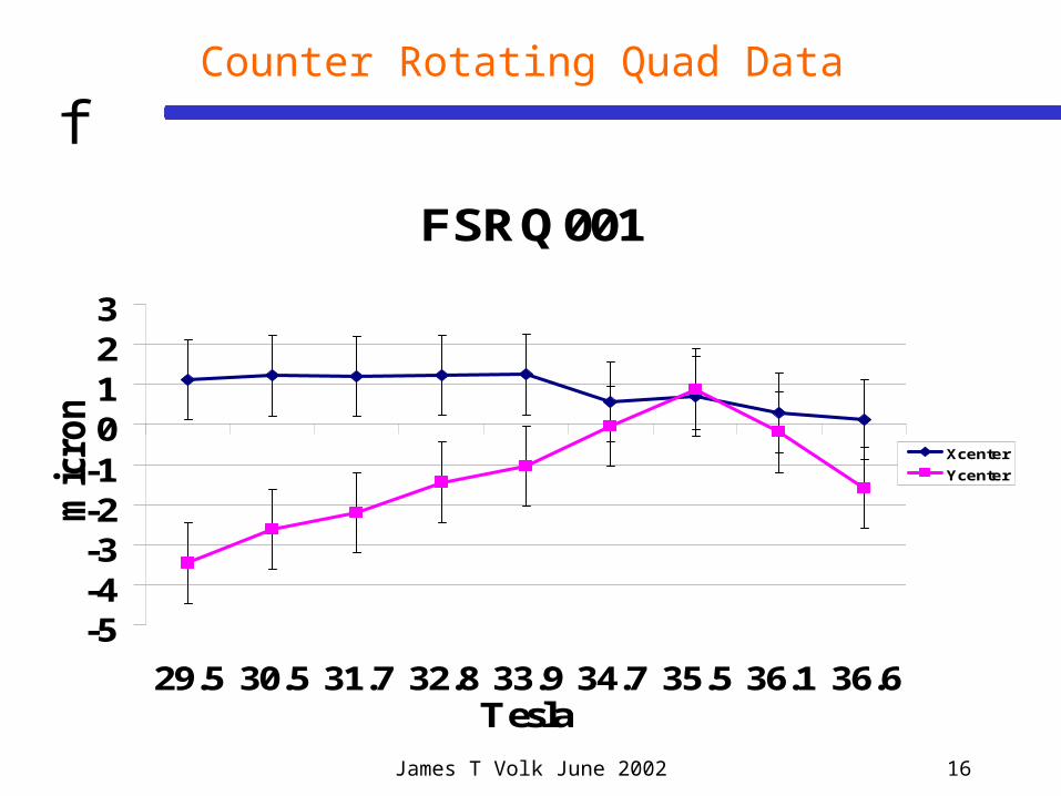
fCounter Rotating Quad Data
FSRQ001
-5-4-3-2-10123
29.5 30.5 31.7 32.8 33.9 34.7 35.5 36.1 36.6Tesla
mic
ron
s
Xcenter
Ycenter

James T Volk June 2002 17
fResults
Max Grad Tesla
Min Grad Tesla
Center Shift Microns
Corner 17.5 14.1 60.0
Wedge 1 23.7 18.4 20.0
Wedge 2 26.4 23.0 >4.0
Sliding Shunt 25.9 21.8 15.0
Rotating 36.3 30.3 4.5
Electromagnet 33.2 27.4 1.0

James T Volk June 2002 18
fIssues
• Improve center stability• Time stability• Temperature stability• Motor controls• Optimize Design• New Designs

James T Volk June 2002 19
fLBNL & SLAC work on designing magnets (PMs and EMs)
for the damping rings
• Main Damping Ring lattices have been published with detailed requirements on all magnets
• Have 2-D model of DR quadrupoles and transport line dipoles. The Nd Iron style magnets are of reasonable size
• Investigated the Nd Iron quads, with rotating rods to generate the +/-10% adjustability, in more detail to see if they could meet all the requirements.
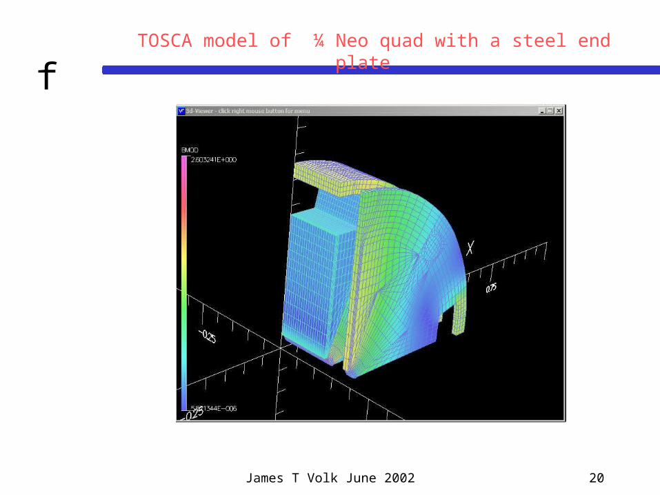
• Jin-Young Jung (LBNL) used TOSCA to make a 3-D model of damping ring magnets
James T Volk June 2002 20
fTOSCA model of ¼ Neo quad with a steel end plate
James T Volk June 2002 21
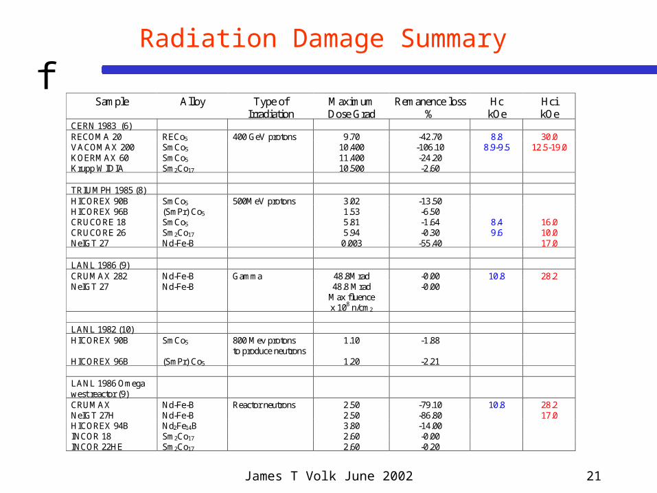
fRadiation Damage Summary
Sample Alloy Type ofIrradiation
MaximumDose Grad
Remanence loss%
HckOe
HcikOe
CERN 1983 (6)RECOMA 20 RECo5 400 GeV protons 9.70 -42.70 8.8 30.0VACOMAX 200 SmCo5 10.400 -106.10 8.9-9.5 12.5-19.0KOERMAX 60 SmCo5 11.400 -24.20Krupp WIDIA Sm2Co17 10.500 -2.60
TRIUMPH 1985 (8)HICOREX 90B SmCo5 500MeV protons 3.02 -13.50HICOREX 96B (SmPr) Co5 1.53 -6.50CRUCORE 18 SmCo5 5.81 -1.64 8.4 16.0CRUCORE 26 Sm2Co17 5.94 -0.30 9.6 10.0NeIGT 27 Nd-Fe-B 0.003 -55.40 17.0
LANL 1986 (9)CRUMAX 282 Nd-Fe-B Gamma 48.8Mrad -0.00 10.8 28.2NeIGT 27 Nd-Fe-B 48.8 Mrad -0.00
Max fluencex 108 n/cm2
LANL 1982 (10)HICOREX 90B SmCo5 800 Mev protons
to produce neutrons1.10 -1.88
HICOREX 96B (SmPr) Co5 1.20 -2.21
LANL 1986 Omegawest reactor (9)CRUMAX Nd-Fe-B Reactor neutrons 2.50 -79.10 10.8 28.2NeIGT 27H Nd-Fe-B 2.50 -86.80 17.0HICOREX 94B Nd2Fe14B 3.80 -14.00INCOR 18 Sm2Co17 2.60 -0.00INCOR 22HE Sm2Co17 2.60 -0.20
James T Volk June 2002 22
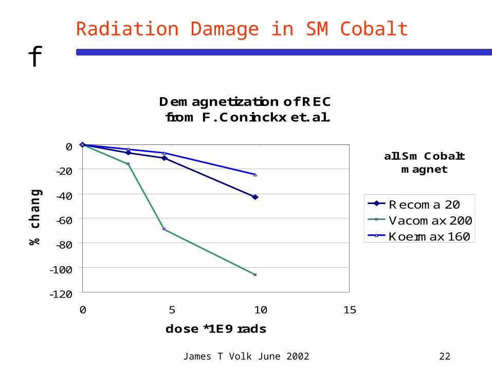
fRadiation Damage in SM Cobalt
Demagnetization of RECfrom F. Coninckx et. al.
-120
-100
-80
-60
-40
-20
0
0 5 10 15
dose *1E9 rads
% c
ha
ng
e
Recoma 20
Vacomax 200
Koermax 160
all Sm Cobalt magnet

James T Volk June 2002 23
f
Radiation-Induced Demagnetization(Japanese experience with 200 MeV protons)
• Material Type has large impactRed: N48 High Br (1.4T)
Low Hc (1.15 MA/m)
Blue: N32Z Lower Br (1.14 T)Higher Hc (2.5
MA/m)
• Material Shape has large impact(All samples are discs 10 mm dia)Circle: thickness = 2 mm (Pc = 0.5)Triangle: thickness = 4 mm (Pc = 1.0)Square: thickness = 7 mm (Pc = 2.0)- Higher Permeance coefficient
increases resistance (x 10)
• SmCo is much more resistant than NdFeB
James T Volk June 2002 24
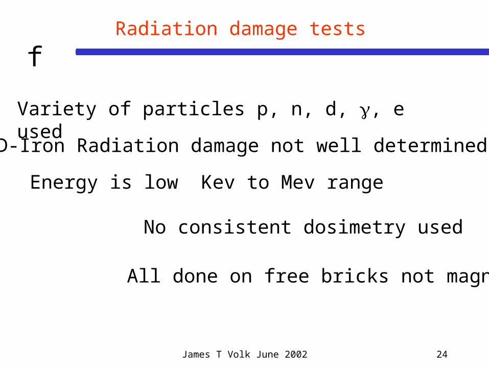
fRadiation damage tests
Variety of particles p, n, d, , e used
ND-Iron Radiation damage not well determined
Energy is low Kev to Mev range
No consistent dosimetry used
All done on free bricks not magnets!
James T Volk June 2002 25
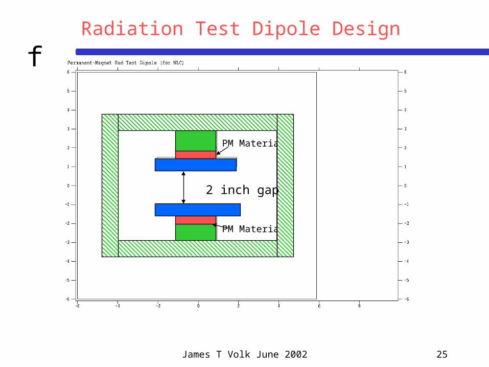
fRadiation Test Dipole Design
PM Material
PM Material
2 inch gap
James T Volk June 2002 26
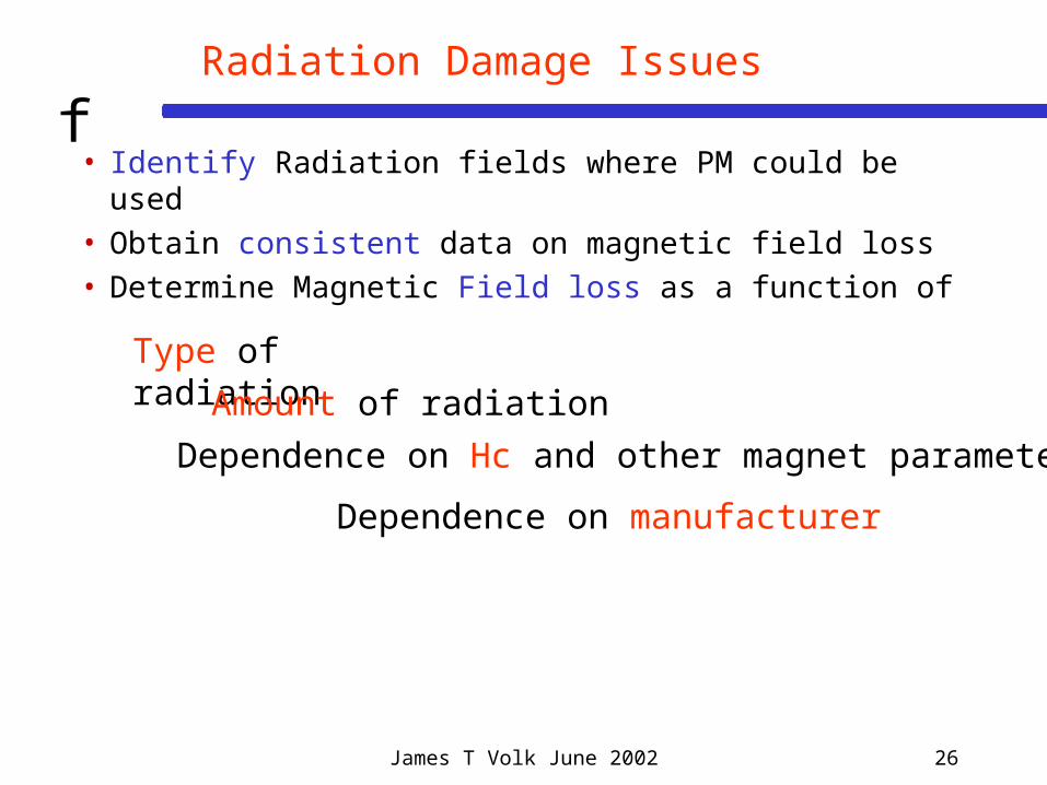
fRadiation Damage Issues
• Identify Radiation fields where PM could be used• Obtain consistent data on magnetic field loss• Determine Magnetic Field loss as a function of
Type of radiationAmount of radiation
Dependence on Hc and other magnet parameters
Dependence on manufacturer
James T Volk June 2002 27
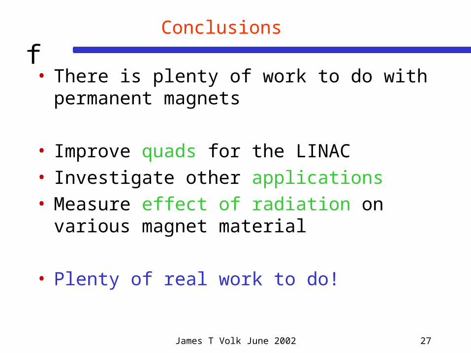
fConclusions
• There is plenty of work to do with permanent magnets
• Improve quads for the LINAC• Investigate other applications• Measure effect of radiation on various magnet
material
• Plenty of real work to do!