p.e.s. college of engineering, mandya - 571 401pescemandya.org/pdf/ee/ee_model_qp.pdf ·...
TRANSCRIPT

P.E.S. College of Engineering, Mandya - 571 401
(An Autonomous Institution affiliated to VTU, Belgaum)
Seventh Semester, B.E. - Electrical and Electronics Engineering Model paper: AC&DC Drives(P15EE73)
Time: 3 hrs Max. Marks: 100
Note: i) Answer FIVE full questions, selecting ONE full question from each Unit. ii) Assume suitable missing data if any.
UNIT - I M
1. a. Draw the block diagram of electric drive and explain each components of it. 4
b. With the basic fundamentals Derive and explain the speed torque characteristics of dc shunt motors.
6
c. Explain and analyze the operation of single phase half controlled converter fed separately excited dc drive under discontinuous mode with relevant circuit and waveforms. 10
2 a. Explain and analyze the operation of single phase fullycontrolled converter fed separately excited dc drive under discontinuous mode with relevant circuit and waveforms.
12
b. Explain the four quadrant operating modes of separately exited DC motor and state the conditions to be satisfied for each quadrant.
8
UNIT - II
3 a. Explain and analyze the operation of three phase half controlled converter fed dc series motor drive under discontinuous mode with relevant circuit and waveforms
10
b. Explain and analyze the operation of single phase dual converter with relevant circuit and waveforms with circulating current mode
10
4 a. Explain and analyze the operation of three phase fully controlled converter fed separately excited dc drive under continuous mode with relevant circuit and waveforms 10
b. Explain the operation of four quadrant chopper with the circuit diagram & operating characteristics.
10
UNIT - III
5 a. Derive an expression for closed loop control of a separately excited DC motor for change in voltage.
10
b. Explain in briefly the various types of breaking in DC motor. 10 6. a Derive an expression for closed loop control of a separately excited DC motor for change
in load torque. 10
b. With the help of block diagram explain the closed loop control scheme for a DC drive using micro computer.
10
UNIT - IV
7 a. Derive & explain the performance equations of an IM Drive
10
b. With neat circuit and wave forms explain the operation VSI fed IM drive 10
8 a. Using (V/F)control principle explain how speed control for IM Drive 10
b. With Necessary Circuit and Speed Torque Curve explain the operation of static scherbius drive
10
U.S.N

UNIT - V
9 a. Explain the variable frequency control scheme for true synchronous mode of operation of synchronous motor drive
10
b. Draw the single line diagram and explain the various stages of operation in paper mill 10
10 a. With Necessary Circuit and waveforms explain the operation of self controlled synchronous motor drive employing load commutated inverter
10
b. Draw the single line diagram and explain the various stages of operation in rolling mill 10

SI.NO Model Question Paper Marks CO’s Levels
UNIT-I
1.a) For the clamping circuit shown draw the output waveform assume VT = 0.7V
07 CO1 L3
b) For a voltage divider bias configuration derive an expression for Ic & VCE 07 CO1 L2
c) Explian Frequency Response of RC Coupled Amlifier. 06 CO1 L4
2.a) Assume ideal diode for the circuit shown below, Draw the output waveform for
the given input signal
07 CO1 L3
b) Explain various distortions of amplifiers. 06 CO1 L1
c) With Circuit diagram explain voltage doubler circuit. 07 CO1 L2
UNIT-II
3.a) With the help of circuit diagram explain the RC Phase shift oscillator? State
condition for sustained oscillations.
07 CO2 L2
b) A transistor connected as a commmon emitter amplifier is driving a load of
10k. It is supplied by a source of 1K internal resistance. The hybrid parameters
of the transistors used are hie =1100Ω, hfe=2.5x10⁻⁴ , hoe=1/40k. Find a)
current gain b)voltage gain c) input impedence d)output impedence.
07 CO2 L3
c) Draw the circuit diagram and explain the working of crystal oscillator. 06 CO2 L2
4.a) Differentiate between RC Phase shift and wein bridge oscillator. 06 CO2 L2
b) Transisitor amplifier using h-Parameter derive an expression for i) Current gain
ii) input impedence iii) Voltage gain
08 CO2 L3
c) From the two port network & hybrid model.Derive an expression for hybrid
parameters.
06 CO2 L4
UNIT-III
5.a) Derive an expression for gain of a negative feedback amplifier. 05 CO3 L3
b) Obtain magnitude and phase angle of gain at different frequecies for a low
frequecy response of the amplifer and plot gain and phase.
08 CO3 L3
c) Explain Current shunt and Current series Feedback amplifier. 07 CO3 L2

6.a) Obtain magnitude and phase angle of gain at different frequecies for a High
frequecy response of the amplifer and plot gain and phase .
08 CO3 L3
b) Explain RC Coupled amplifier and explain its frequency response. 05 CO3 L4
c) Explain Voltage series & Voltage shunt feedback amplifier. 07 CO3 L2
UNIT-IV
7.a) Explain series fed class A power amplifer ? Derive an expression for PO(ac) 07 CO4 L2
b) A class A transformer coupled audio power amplifier is required to derive a
maximum of 100W into a loud speaker of 10Ω resistance. If the output
resistance of the amplifier is 1000Ω calculate
a) turns ratio of the transformer required
b) Power supply voltage . assume an ideal transformer h
08 CO4 L3
c) A transistor supplies 0.85W to a 4K load. The zero signal DC Collector current
is 31 Ma and the dc collector current with signal is 34mA. Determine the
second harmonic
05 CO4 L3
8.a) Explain the working of Class-B push-pull power amplifier 08 CO4 L4
b) what is harmonic distortion ? obtain an expression for collector current interms
of second harmonic distortion
08 CO4 L2
c) A class A Series fed power amplifier is required to deliver a maximum power
of 20W to a load of 4Ω. Calculate the rquired supply voltage
04 CO4 L3
UNIT-V
9.a) Explain inverting and non-inverting op-amp circuit 08 CO5 L4
b) Explain the working of Schmitt Trigger using op-amp 06 CO5 L2
c) List the characteristics of Ideal OP-Amp 06 CO5 L1
10. a) With neat figure explain the working of R-2R ladder D/A, successive
approximation A/D Converter
10 CO5 L2
b) Explain following op-amp circuits
1. Differential Amplifier 2. Comparators and 3.Voltage follower.
10 CO5 L2
Model Question Paper
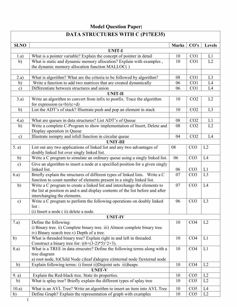
DATA STRUCTURES WITH C (P17EE35)
SI.NO Marks CO’s Levels UNIT-I
1.a) What is a pointer variable? Explain the concept of pointer in detail 10 CO1 L1 b) What is static and dynamic memory allocation? Explain with examples ,
the dynamic memory allocation function MALLOC( ) 10 CO1 L2
2.a) What is algorithm? What are the criteria to be followed by algorithm? 08 CO1 L3 b) Write a function to add two matrices that are created dynamically 06 CO1 L4 c) Differentiate between structures and union 06 CO1 L4
UNIT-II 3.a) Write an algorithm to convert from infix to postfix. Trace the algorithm
for expression (a+b)/(c+d) 10 CO2 L2
b) List the ADT’s of stack? Illustrate push and pop an element in stack 10 CO2 L3
4.a) What are queues in data structures? List ADT’s of Queue 08 CO2 L1 b) Write a complete C-Program to show implementation of Insert, Delete and
Display operation in Queue 08 CO2 L2
c) Illustrate isempty and isfull function in circular queue 04 CO2 L4 UNIT-III
5. a) List out any two applications of linked list and any two advantages of doubly linked list over singly linked list.
08 CO3 L2
b) Write a C program to simulate an ordinary queue using a singly linked list. 06 CO3 L4
c) Give an algorithm to insert a node at a specified position for a given singly linked list.
06
CO3
L1
6.a) Briefly explain the structures of different types of linked lists. Write a C function to count number of elements present in a singly linked list.
07 CO3 L3
b) Write a C program to create a linked list and interchange the elements to the list at position m and n and display contents of the list before and after interchanging the elements.
07 CO3 L4
c) Write a C program to perform the following operations on doubly linked list : (i) Insert a node ( ii) delete a node.
06 CO3 L3
UNIT-IV 7.a) Define the following:
i) Binary tree. ii) Complete binary tree. iii) Almost complete binary tree. iv) Binary search tree.v) Depth of a tree.
10 CO4 L2
b) What is threaded binary tree? Explain right in and left in threaded. Construct a binary tree for: ((6+(3-2)*5)^2+3).
10 CO4 L1
8.a) What is a TREE in data strucutre? Define the following terms along with a tree diagram a) root node, b)Child Node c)leaf d)degree e)internal node f)external node
10 CO4 L1
b) Explain following terms: i) forest ii)Disjoint sets iii)heaps 10 CO4 L2 UNIT-V 9. a) Explain the Red-black tree. State its properties. 10 CO5 L2 b) What is splay tree? Briefly explain the different types of splay tree 10 CO5 L2
10.a) What is an AVL Tree? Write an algorithm to insert an item into AVL Tree 10 CO5 L4 b) Define Graph? Explain the representation of graph with examples 10 CO5 L2

P.E.S. College of Engineering, Mandya - 571 401
(An Autonomous Institution affiliated to VTU, Belgaum)
Seventh Semester, B.E. - Electrical and Electronics Engineering Model paper: Digital Electronic Circuits(P17EE34)
Time: 3 hrs Max. Marks: 100
Note: i) Answer FIVE full questions, selecting ONE full question from each Unit. ii) Assume suitable missing data if any.
UNIT - I M
1. a. Realize the X-OR function using i)AOI logic ii)NAND logic iii)NOR logic 8
b. Prove that i) (X + Y). (W'X'Z) + (X + Y). (W'X'Z)'= x+y
ii) ABC + ABC' + AB'C + A'BC = AB + AC + BC 6
c. Complement of function in sum-of-products form
i) F= A’B’C’ + A’BC’ + AB’C’
ii) F = A’B’C + A’BC + AB’C + ABC’ + ABC
6
2 a. Subtract 14 from 46 using the 8-bit 2’s complement arthmetic 6
b. State and prove i) consensus theorem ii) transposition theorem 8
c. Complement of function in product-of-sums form
i) (A + B + C’) (A + B’ + C’) (A’ + B + C’) (A’ + B’ + C) (A’ + B’ + C’)
ii) (A + B + C) (A + B’ + C) (A’ + B + C)
6
UNIT - II
3 a. F(A,B,C,D)=∑ (0,1,3,5,6,11,12,13,14) reduce by k-map
i) SOP form ii) POS form realize using i) AOI Logic ii) NAND Gates 10
b. Obtain the minimal expression for F=(A,B,C,D)=∑ (1,2,3,5,6,7,8,9,12,13,15) using
Tabular method 10
4 a. What is Full adder? Realize Full adder using i) NAND Gates ii) NOR Gates 10
b. What is parallel adder? Design four bit look ahead carry generator 10
UNIT - III
5 a. Give the comparison between encoder and decoder 4
b. What is flip flop? Discuss the working of SR flip flop with its truth table and timing
diagram 8
c. Obtain the characteristic equations of:
i ) JK Flip-flop ii) T-flip-flop iii) D-Flip-flop 8
U.S.N

6. a Give the comparison between multiplexer and demultiplexer 5
b. Configure a 5:32 decoder using four 3:8 decoder IC’s and a 2:4 decoder IC 7
c What is race around condition in Flip-flops? Explain how it is eliminated? 8
UNIT - IV
7 a. with neat timing diagram, explain the working of a 4 bit SISO register. 10
b. Design a synchronous mod 6 up counter using JK flip flop 10
8 a. Explain mealy and Moore models of a clocked synchronous sequential network 10
b. With the help of logic diagram and state diagram explain the operation of Johnson
Counter and ring counter 10
UNIT - V
9 a. With the aid of a circuit diagram, explain the operation of 2-input TTL NAND gate With
Totem-pole output 10
b. Draw a 4 bit D/A converter using R-2R resistors and explain its working 10
10 a. what is accuracy and resolution of the D/A converter? What is the resolution of a 12-bit
D/A converter which uses a binary ladder? If the full scale o/p is +10Volts what is the
resolution in volts.
10
b. Explain the operation of 2-input CMOS NOR gate with the help of a circuit diagram 10


P17EE44
Page number… 1
P.E.S. College of Engineering, Mandya - 571 401
(An Autonomous Institution affiliated to VTU, Belagavi)
Fourth Semester, B.E. –Model Question Paper Electromagnetic Field Theory
Time: 3 hrs Max. Marks: 100
Note: Answer FIVE full questions, selecting ONE full question from each unit.
UNIT-I
1 a. State and explain coulomb’s law in vector form. 6
b. Point charges of 50nC each are located at A(1, 0, 0), B(-1, 0, 0), C(0, 1, 0)
and D(0, -1, 0) meters. Find the total force on charge at A. 7
c. Determine E at P(1, 1, 1) caused by 4 identical, 3nC point charges located at 7
P1(1, 1, 0), P2(-!, 1, 0), P3(-1, -1, 0), and P4(1, -1, 0).
2 a. Explain the terms: (i) Electric Flux and (ii) Electric flux density. 6
b. Starting from fundamental prove Gauss divergence theorem 7
c. Given, D=x2ax+xyay+yzaz; C/m2. Verify divergence theorem over a cube of 7
one unit for each side. The cube is situated in the first actant of the
Cartesian coordinate system with one corner at the origin.
UNIT-II
3 a. Bring out the relation between electric field intensity and electric potential. 6
b. Determine the work done in carrying a charge of -2C from (2, 1,-1) to (8, 2, -1) 8
in the electric field E=yax + xay; v/m, considering the path along the parabola
x=2y2
c. Derive an expression for energy density in an electrostatic field 6
4 a. Starting from fundamental derive the expressions for Laplace and Poison’s 7
equations.
b. Determine whether or not the following field satisfies Laplace equation. 7
(i) V=x2-y2+z2 (ii) V = ῤ*cosɸ+z.
c. Discuss the application of Laplace equation to concentric spherical conductor 6
system.
U.S.N

P17EE44
Page number… 2
UNIT-III
5 a. Derive the continuity equation of current in integral and point differential form. 6
b. Discuss the properties of a conductor subjected to electric field. 6
c. Discuss the nature of dielectric material 8
6 a. Discuss the boundary conditions between two dielectric medium interfaces. 8
b. The region z<0 is composed of a uniform dielectric material with ὲr=3.2 and 6
the region z>0 is characterized by ὲr=2. If D1=(-30ax+50ay+70 az); nC/m2,
determine (i) D2 (ii) ɵ1 and (iii) ɵ2
c. Derive the expression for capacitance of a coaxial cable. 6
UNIT-IV
7 a. State Biot-Savart’s law. Derive the expression for magnetic flux density at a 6
given point due to a current carrying element of finite length.
b. Explain the concept of scalar and vector magnetic potential. 6
c. State and prove Stroke’s theorem 8
8 a. Write a note on magnetic flux, magnetic flux density and give magnetic field 6
properties.
b. State and prove ampere’s law. 6
c. Using Ampere’s law find the magnetic field due to solid cylindrical conductor. 8
UNIT-V
9 a. Two homogeneous, linear, isotropic material have interface at x=0 in which 7
there is a surface current k=200uz; A/m. For x<0, ur=2 and H1= (150ax+400ay+250uz);
AT/m. In region 2, when x>0, find (i) H2 (ii) |B1| and (iii) α1
b. State and explain Faraday’s law of electromagnetic induction. Write the point 7
form of it.
c. Derive the Maxwell’s equation based on ampere’s circuital law for time 8
varying fields.
10 a. Derive an expression for force on a moving charge. 6
b. Derive the expression for inductance of a solenoid. 6
c. Derive the expression for force between two current carrying conductors. 8

P15EE552 Page No... 1
P.E.S. College of Engineering, Mandya - 571 401
(An Autonomous Institution affiliated to VTU, Belgaum) Fifth Semester, B.E. - Electrical and Electronics Engineering
FUZZY LOGIC – P15EE552 Model Paper
Time: 3 hrs Max. Marks: 100
Sl. No.
Model Questions Marks
Unit-I
1(a) Define the different operation on classical (crisp) sets. Give suitable example for each type of operations.
06
.(b) Define fuzzy sets? For the given two fuzzy sets, A & B, Find the followings:
=
+
.
+
.
+
.
+
+
.
And, =
.
+
.
+
.
+
.
+
.
+
() ∪ () ∩ () A ∩ () ∩ () ∪ () ∪ (vii) ∩
08
.(c) Consider two fuzzy sets. = .
+
.
+
.
& =
.
+
.
+
.
+
. Find the
algebraic sum, algebraic product, bounded sum, bounded difference of the given Fuzzy sets.
06
2(a) Discuss various the operations on fuzzy sets and mention their properties.
08
.(b) For the given two fuzzy sets as shown in fig.2 (b), Find graphically (i) ∪ (ii) ∩ and (iii) prove that (AUB) = ∩
Figure.2.(b)
05
.(c) 2.(c) Given the two fuzzy sets A& B.
= .
+
.
+
+
.
+
.
And, =
.
+
.
+
+
.
+
.
Find the following: (i) (ii) (iii) A U B () ∩ (v) A|B (vi) (A+B) (vii) (A•B)
07
Unit-II 3(a) List and discuss the operations on classical relation. Explain briefly the composition of
crisp or classical relations.
06
U.S.N

P15EE552 Page No... 2
.(b) Explain briefly the composition of fuzzy relation.
06
.(c) Find the fuzzy Cartesian product using "Min-Max" composition, for the given fuzzy sets.
= .
.+
.
.+
+
.
.+
.
. , V=
.
+
.
+
+
.
+
.
and
= .
.+
.+
.
.
Find (i) T = I x C, (ii) P = V x I (iii) E = P • T.
08
4.(a) What are tolerance and equivalence relations? Describe the classical equivalence relations.
06
.(b) Explain with suitable diagrams and examples fuzzy equivalence relations.
06
.(c) For a speed control of a D.C. motor , the membership functions of series resistance Rse, armature current Ia and speed N are given as follows:
Given: Rse= .
+
.
+
.
+
.
,
Ia= .
+
.
+
.
+
.
+
.
+
.
and N=
.
+
.
+
.
+
.
Find: i) Fuzzy Cartesian product, R = Rse X Ia ii) Fuzzy Cartesian product, S = Ia X N iii) T = R • S using max- min composition.
08
Unit-III 5(a) Explain briefly the features of the membership functions with relevant figures. List the
various methods employed for the membership value assignment.
08
.(b) Explain the inference method adopted for assigning membership values. Using inference approach, obtain the membership values for the different triangular shapes (I, R, T) for a triangle with angles 400, 600, and 800.
06
.(c) Given three (3) fuzzy sets as shown in fig.6(c), Find z* using COG method.
06
6(a) Explain briefly core, support, boundaries, convexity, normality and cross over points with reference to membership functions.
08
.(b) Define fuzzyfication. Discuss in detail the membership value assignments using angular fuzzy sets.
06
.(c) Explain briefly the Lambda cuts for fuzzy sets and fuzzy relations. Determine the defuzzyfier output by these methods: Centre Of Gravity (COG) defuzyfication, Sum Of
06

P15EE552 Page No... 3
Average (Centre Of Sum) and Centre Of Average defuzzyfication method for given fuzzy sets:
Unit-IV
7(a) What are linguistic variables and linguistic hedges? Explain their relevance in fuzzy logic.
08
.(b) Discuss with examples, the fuzzy logic propositions.
06
.(c) Explain how fuzzy conditional (IF-THEN) production rules are interpreted? Illustrate with suitable examples.
06
8(a) What is approximate reasoning? Describe the general Inference rules used in Approximate reasoning.
07
.(b) In computer systems there is a relationship between CPU board temperatures and power supply voltage. Following membership functions are defined :
"Temperature is high" , = .
+
.
+
.
+
.
+
And, "Voltage is low”, =
.+
.
.+
.
.+
.
.+
.
(i) Using classical implication, find relation A→B (ii) Suppose we consider another temperature; say A1 = “temperature is high.”
"Temperature is high" , 1 =
+
.
+
.
+
.
+
Find appropriate voltage for this temperature using max - product composition with the relation found in sub question (i).
06
.(c) With a block diagram explain the feature of Fuzzy Information Systems (FIS).
07
Unit-V 9(a) With a neat diagram, explain the architecture of a fuzzy logic controller (FLC).
10
.(b) What are the steps involved in designing a fuzzy logic controller?
05
.(c) Give the design elements that are adopted for the design of general FLC system.
05
10(a) What are the special forms of FLC system models? Explain.
05
.(b) List the various applications of fuzzy logic controller.
05
.(c) With a suitable application case study, explain a fuzzy logic controller. 10

P.E.S. College of Engineering, Mandya - 571 401
(An Autonomous Institution under VTU, Belgaum) Eighth Semester, B.E. – Electrical and Electronics Engineering
Model Question Paper HVDC Power Transmission (P15EE831)
Time: 3 hrs Max. Marks: 100
Note: i) Answer any FIVE full questions, selecting at least TWO full questions from each part
ii) Smith chart will be provided.
Marks COs Levels 1. a. Compare AC and DC transmission based on their relative, technical
performance and reliability. 10 CO1
L4
b. Mention the principle applications and limitations of DC transmission.
6 CO1 L2
c. Explain the various types of DC links along with their schematic connections diagrams.
4 CO1 L2
or 2. a. State any three HVDC projects in India and mention their technical
specifications. 6
CO1 L1
b. Bring out the comparison between AC and DC transmission systems on the economics of power transmission front. Explain the significance of ‘Breakeven distance’ in this context.
6 CO1 L4
c. Discuss the choice of optimum system voltage for a fixed power transfer over long distance transmission lines.
8 CO1 L6
3.a. Discuss the turn- on and turn – off switching characteristics of thyristor.
10 CO2 L5
b. Discuss the properties of converter circuits. 5 CO2 L6 c. Define pulse number and comment on choice of best converter
configuration. 5
CO2 L1
or 4.a. With neat circuit diagram, explain three phase one way rectifier and
derive an expression for Vd 10
CO2 L2
b. Explain the characteristics of a twelve pulse converter 10 CO2 L2 5.a. Perform the analysis of Gratez circuit with overlap less than 60
degrees. Obtain the expression for average direct voltage in each case.
10 CO3 L3
b. A bridge connected rectifier is fed from 220 kV / 110 kV transformer with primary connected to 220 kV. Determine the DC output voltage when the communtation angle is 15º and delay angle is 30º.
10
CO3 L5
or 6. a. A Graetz circuit operating at 50 Hz has a line to line voltage of
440V. Considering AC line inductance ‘Lc’ = 1 Henry, alpha = 15 and u = 10. Compute: i) Average current and voltage ii) Equivalent Communication resistance. Also draw the equivalent circuit of the bridge converter
12
CO3 L1
b. Perform the analysis of Gratez circuit without overlap. Obtain the expression for average direct voltage.
8 CO3 L3
7. a. Explain the basic principles of controlling the voltage at any point 10 CO4 L2

on the DC line and the current. Mention the considerations influencing the selection of control characteristics.
b. Discuss the actual characteristics of converter control. In this context, explain the significance of current margin and its range.
10 CO4 L5
or 8. a. Mention the limitations of manual control. 5 CO4 L1 b. What are MTDC systems? Explain the two configurations of MTDC
systems. 5
CO4 L1
c. What is mode ambiguity and in this context explain the modification of V-I characteristic for mode stabilization.
10 CO4 L1
9. a. Explain the basic types of faults that can occur in converters 10 CO5 L2 b. Discuss the procedure for clearing the line faults and re-energizing
the line. 10
CO5 L6
or
10. a. Explain the phenomenon of ‘Telephone interference’ and the factors affecting it in detail.
10 CO5 L2
b. Define Characteristic and Non-characteristic harmonics. Explain the troubles caused by harmonics and functioning of harmonics filters.
10 CO5 L1

P.E.S COLLEGE OF ENGINEERING, MANDYA-571 401 (An Autonomous Institution under VTU, Belgaum)
VII Semester BE (Electrical & Electronics Engineering) Course with code: High Voltage Engineering (P15EE72)
MODEL QUESTION PAPER Time: 3Hrs Max marks. 100
marks CO’s Level
1 a. Discuss the need for generation of high voltages in laboratory. 5 CO1 L1
b. Derive an expression for growth of current in gaseous medium under uniform field condition assuming both Townsend’s first and second ionization process to be in progress.
10 CO1 L3
c. Discuss breakdown phenomena in electro negative gases. 5 CO1 L4
OR 2 a. Explain Suspended particle theory of breakdown in liquid dielectrics. 8 CO1 L2 b. What is Paschen’s law? Discuss the breakdown effect of breakdown voltage over a
wide range for the product of pressure and gap spacing. 8 CO1 L1
c. Explain thermal breakdown phenomenon in solid dielectrics. 6 CO1 L2 3 a. What is Paschen’s law? Discuss the effect of breakdown voltage over a wide range
for the product of pressure and gap spacing. 10 CO2 L3
b. Explain suspended particle theory of breakdown in liquid dielectrics. 5 CO2 L2 c. Explain thermal breakdown phenomena in solid dielectrics. 5 CO2 L1 OR 4 a. Explain how HVDC is generated using Cockroft – Walton voltage multiplier circuit. 8 CO2 L2 b. Derive an expression for ripple voltage and regulation using Cockroft – Walton
Voltage multiplier circuit. 8 CO2 L3
c. Explain how HVAC is generated using cascaded transformer. 6 CO2 L2 5 a. Explain how HVAC can be generated using Tesla coil. 5 CO3 L2 b. Explain with neat sketch three stage cascade connection of transformer for producing
HVAC. 10 CO3 L2
c. A 100 kVA, 400 V/250 kV testing transformer has 8% leakage reactance and 2% resistance on 100 kVA base. A cable has to be tested at 500 kV using the above transformer as a resonant transformer at 50 Hz. If the charging current of the cable at 500 kV is 0.4 A, find the series inductance required.
5 CO3 L4
OR
6 a. An impulse current generator has a total capacitance of 8 uF. The charging voltage is 25 kV. If the generator has to give an output current of 10kA with 8/20us waveform. Calculate The circuit inductance & The dynamic resistance in the circuit.
8 CO3 L4
b. Explain Trigation gap method for triggering an impulse generator. 6 CO3 L2
c. Derive an expression for the output impulse voltage. 6 CO3 L5
7 a. Explain photo ionization phenomena in gas discharges. 6 CO4 L2
b. Explain principle of operation of voltage doubler circuit to generate HVDC. 8 CO4 L2 c. A Cockcroft – Walton type voltage multiplier has eight stages with capacitances all
equal to 0.05 µF. The supply transformer secondary voltage is 125 kV at a frequency of 150 Hz. If the load current to be supplied is 5 mA, find;
6 CO4 L4

(i) The percentage ripple (ii) The regulation (iii) The optimum number of stages for minimum regulation.
OR 8 a. Explain how surge current measurements are made using Klydonograph. 6 CO4 L2 b. Explain how capacitance dividers are used to measure impulse voltage. 8 CO4 L2 c. Explain the construction and working principle of series resistance microammeter for
HVDC measurement. 8 CO4 L3
9 a. Compare standard lightning impulse voltage with standard switching voltage. 5 CO5 L3 b. Explain the construction and principle of operation of five stage marx impulse
generator. 10 CO5 L2
c. Briefly explain the factors affecting the discharge detection 5 CO5 L4 OR 10 a. Explain the high voltage Schering bridge used for capacitance and loss tangent
measurements. 8 CO5 L2
b. Explain the basic principle of PD measurement using straight detector method. 8 CO5 L2 c. Discuss the various tests conducted on Insulators. 4 CO5 L3

Model Question Paper Course Title: Microcontrollers Course Code: P17EE45
UNIT-I
Q.No. Questions Marks CO Blooms
level
UNIT-I
1.
(a)
Give a brief summary about evolution of microcontrollers. 06 CO1 L1
(b) Compare the following: Microprocessors and Micro controllers 06 CO1 L3
(c) Draw the block diagram and Write a note on 8 register of 8051
microcontroller
08 CO1 L3
OR
2.
(a)
Give the Comparison between the RISC and CISC
architectures.
08 CO1 L1
(b) Draw the block diagram of 8051 microcontroller and explain
the special function registers.
06 CO1 L3
(c) Explain the ROM & RAM internal memory organization 06 CO1 L2
UNIT-II
3.
(a)
State and explain the addressing modes used in each of the
following instructions.
i) MOV A, # 25h ii) MOV A, @ Ri iii) MOV R2, 40H
iv) MOVC A, @ A + PC
06 CO2 L2
(b) Explain the following instructions i)MOVX ii)SWAP iii)XCHD 06 CO2 L2
(c) Explain the various bit level logical operation. 08 CO2 L2
OR
4.
(a)
Explain the operation of stack and stack pointer with an example. 06 CO2 L2

(b) What is the need of addressing modes? Explain any three
addressing modes with an example.
06 CO2 L1
(c) Explain the various byte level logical operation 08 CO2 L2
UNIT-III
5.(a) Write a note on jump instructions with their relative program
range.
08 CO3 L1
(b) Explain the following jump instructions with examples:
i) AJMP ii) DJNZ iii) CJNE iv) JZ
06 CO3 L2
(C) Write an ALP to find the sum of ten 8-bit numbers. 06 CO3 L5
OR
6(a) Write a note on CALL instructions with their relative jump
program range.
06 CO3 L1
(b) Write a program to find the largest of a number given in an
array
08 CO3 L5
(c) Explain the following jump instructions with examples:
i) RLC A ii) JNZ iii) RRC A iv) JC
06 CO3 L2
UNIT-IV
7(a) Explain various modes of operation of timers/counters. 06 CO4 L2
(b) Illustrate the contents of TMOD register 06 CO4 L3
( c) Explain the steps involved in mode1 operation of Timer 08 CO4 L2
OR
8(a) What is the difference between timer and counter?Explain with
an example.
06 CO4 L2
(b) Explain the steps involved in mode 2 operation of Timer 08 CO4 L2
(C) Write an ALP to generate a square wave of 100KHz on pin 2.3
using Timer 1 in mode 1. Clock frequency is 22 MHz.
04 CO4 L5
UNIT-V
9 (a) What do you mean by simplex, half duplex and full duplex data 06 CO5 L1

transfers.
(b) What is Interrupt? Compare the interrupt and polling methods 08 L2
(c) Explain the format SCON register in detail. 06 CO5 L2
OR
10 (a) What is serial communication? how is this achieved with 8051
using RS 232 standard
06 CO5 L1
(b) Explain different bits in TCON register 06 CO5 L2
(c ) With the help of vector table explain the various interrupts in
8051.
08 CO5 L2

P.E.S. College of Engineering, Mandya - 571 401
(An Autonomous Institution under VTU, Belgaum) First Semester, B.E. – Electrical and Electronics Engineering
Basic Electrical Engineering (P17EE15/25)
Model Question paper
Time: 3 hrs Max. Marks: 100
Q.No. Questions Marks 1. (a)
Calculate the combined resistance of four conductors of 6, 9, 12 and 18Ω connected in parallel. If current flowing in the circuit is 2A,find the current flowing in the 9Ω resistor.
06
(b) Derive an expression for the energy stored in a magnetic field. 06 (c) State and explain faraday’s laws of electromagnetic induction, Lenz’s law,
Fleming’s right hand rule and Fleming left hand rule. 08
OR 2. (a)
State and explain Kirchhoff’s law. 06
(b) An 8 ohm resistor is in series with parallel combination of two resistors 12Ω and
6Ω the current in the 6 Ω resistor is 5A, determine the total power dissipated in the circuit.
06
(c) Two identical coils of 1200 turns each are placed side by side such that, 60% of the flux produced one coil links the other. A current of 10A in the first coil, sets up a flux of 0.12mwb the current the first coil changes from +10A to -10A in 20ms. Find
i. The self-inductance of the coils ii. The emf induced in both the coils.
08
3. (a)
Define RMS value and derive an expression for RMS value of sinusoidally varying AC voltage.
06
(b) How is current of 10A shared by two impedances Z1= 2-j5Ω , and z2 =
6.708<26.56oΩ
06
(c) Derive an expression for the instantaneous power in a pure capacitor energized by sinusoidal voltage. Draw the wave shapes of voltage, current and power signals involved
08
OR 4. (a)
With a neat sketch briefly explain how an alternating voltage is produced when a coil is rotated in a magnetic field.
06
(b) An inductive coil draws a current of 2A, when connected to a 230V, 50Hz supply. The power taken by the coil is 100W. Calculate the resistance and inductance of the coil.
06
(c) An alternating voltage of e= Emsin is applied across a pure inductor of L H. i. Derive an expression for the resulting current
08

ii. What is its active power consumption? iii. Draw the phase diagram iv. Show the waveforms of voltage, current and power.
5.(a) Obtain the relationship between line voltages and phase voltages in a star
connected balanced, 3-phase supply system. 06
(b) Explain the effect of power factor on two wattmeter readings connected to measure the three phase power.
06
(c) With a neat sketch explain the construction and working of a single phase induction type energy water.
08
6(a) What is necessity of earthing? Explain any one type of earthing.. 06 (b) Explain with neat diagram the working of dynamo meter type wattmeter. 06 (c) A star connected load consists of 6Ωresistances in series with an 8 Ω inductive
reactance in each phase. Asupply voltage of 440V at 50Hz is applied to the load. Find the line current power factor and power consumed by the load.
08
7(a) A three phase, 50Hz 16 pole alternator with star connected winding has 144 slots
with 10 conductors per slot. The flux per pole 24.8 mWb is sinusoidally distributed, the coils are full pitched. Find (i) speed (ii) the line emf. Assume winding factor kd = 0.96.
06
(b) Derive an expression for the torque developed in a DC motor. 06 (c) Draw the cross sectional view of DC machine and explain the function of each
part. 08
OR 8(a) Obtain an expression for emf of an alternator and explain the significance of
winding factor. 08
(b) Discuss the different types of rotor construction of alternator mentioning their typical advantages and applications.
06
(c) A 120V DC shunt motor has an armature resistance of 0.2Ω and shunt field
resistance of 60 Ω. It runs at 1800RPM, when it takes full load current of 40A. Find the speed of the motor while it is operating at half the full load, with load terminal voltage remaining same.
06
9 (a) Explain the principle operation of a single phase transformer and derive its EMF equation.
08
(b) A 3 phase induction motor with 4 poles is supplied from an alternator having 6 poles and running at 10000RPM. Calculate (i) synchronous speed of the induction motor (ii) its speed when slip is 0.04 and (iii) frequency of the rotor emf, when speed is 600RPM.
06
(c) What ate the transformer losses? On what factors do they depend? And how are they minimized.
06
OR 10 (a) Explain the principles of operation of a 3 phase induction motor. 06
(b) Discuss the important features and advantages of squirrel cage and phase wound rotor constructions in an induction motor.
06
(c) A 250KVA, 1ϕ transformer has 98.135% efficiency at full load and 0.8 lagging p.f. the efficiency at half load and 0.8 lagging p.f is 97.751%. Calculate the iron loss and full- load copper loss.
08


P.E.S. College of Engineering, Mandya - 571 401
(An Autonomous Institution affiliated to VTU, Belgaum)
Third Semester, B.E. - Electrical and Electronics Engineering
Subject/Code: Electrical Measurements and Instrumentation (P17EE36)
Model Question Paper
Time: 3 hrs Max. Marks: 100
Note: Answer FIVE full questions, selecting ONE full question from each Unit.
Unit-I
Q1a) Write short notes on SI system of units stating the advantages of it. 7M
b) The eddy current loss in a round wire/unit length is given by, ecbae dfBP max , find the
values of a, b, c and e using dimensional analysis and write the equation for Pe. 7M
c) The expression for the eddy current produced in a metallic former moving in the field of a
permanent magnet is found as, lb
BlbakIe
2, check for the dimensional correctness of the
equation. 6M
Q2a) Describe the construction and working principle of single phase energy meter 7M
b) The meter constant of a 230V, 10 A energy meter is 1800 rev/kwhr. The meter is tested at half load and rated voltage at upf. The meter is found to make 80 revolutions in 138 seconds. Determine the meter error at half load. 6M
c) Explain the special features of electrodynamometer type wattmeter so that it can be used for LPF measurement. 7M
Unit-II
Q3a) A supply of 450 Hz is given between a and c and the detector is connected between b and d of the bridge. Arm ab is an unknown impedance, arm bc=200 ohm resistance, arm ad=0.5 microfarad standard capacitor in series with a resistance of 5.2 ohm and arm cd=2850 ohm resistance. Find the elements of unknown arm impedance and its dissipation factor at balance. 6M
b) Define sensitivity of the Wheatstone’s bridge and hence obtain an expression for the bridge sensitivity. 7M
c) With the help of circuit and phasor diagram show that how unknown inductance can be measured using Anderson’s bridge. 7M
Q4a) The ratio arms of a Kelvin’s double bridge are 100 ohm each. Rg=500 ohm. Sensitivity, K=200 mm/microampere, R=0.1002 ohm and S=0.1 ohm. A current of 10 A is passed through R and S from a 2.2 volts battery in series with a rheostat. Neglecting the link resistance, find; (1) Galvanometer deflection (2) Total internal resistance of the battery. 7M

b) With the help of circuit and phasor diagram show that how the unknown capacitance can be measured using Schering Bridge. 7M
c) Write short notes on (i) Sources and detectors (ii) Shielding of bridge. 6M
Unit-III
Q5a) What are shunts and multipliers, explain. 7M
b) A moving coil instrument has a resistance of 5 ohm and gives a full scale reading of 50 mA. Calculate (i) the resistance value required to increase the range to 200 A (ii) the resistance value required to increase the range to 750 V (iii) the power consumed in both cases. 7M
c) Discuss the advantages of instrument transformers over shunts and multipliers. 6M
Q6a) With the help of equivalent circuit and phasor diagram write the expressions for ratio and phase angle of CT, naming the terms involved. 7M
b) A potential transformer of ratio 2000/100 -Volts has the following constants, rp=105 ohm, rs=0.7 ohm, xp=75.2 ohm, xs=0.087 ohm. The no load current is 0.03 A at 0.36 pf lag. Find (i) phase angle error at no load (ii) phase angle error on a load of 5 A at 0.92 pf lag (iii) Burden in VA at upf to have zero phase angle. 7M
c) Define and explain turns compensation in CTs and PTs. 6M
Unit-IV
Q7a) With the help of block diagram, explain the working of Electronic energy metre. 7M
b) Mention the different types of digital voltmeters (DVM) and hence, explain successive approximation type DVM. 7M
c) Explain the procedure for interfacing resistive transducers to electronic circuits. 6M
Q8a) What are transducers? Discuss the classification of transducers. 6M
b) With a neat sketch, explain the use of LVDT in displacement measurement. 7M
c) The resistance of strain guage wire with a guage factor of 2 is bonded to steel structure, subjected to a stress of 100 MN/m2. The modulus of elasticity of steel is 200 GN/m2. Calculate the % change in the value of guage resistance due to applied stress. 7M
Unit-V
Q9a) A coil with a resistance of 10 ohm is connected in direct connection in Q meter. Resonance occurs when the oscilloscope frequency is 1MHz and the resonating capacitor is 65 pF. Calculate the % error introduced in the calculated value of Q when a resistance of 0.02 ohm is inserted. 4M
b) With a neat sketch, explain the working of a dual trace oscilloscope. 8M
c) Discuss the role of lissajious figures in frequency and amplitude measurement. 8M
Q10a) Write short notes on LCD and LED display. 6M

b) With the help of neat sketch, explain the working of digital storage oscilloscope. 8M
c) With a neat sketch, explain the working of XY-recorder. 6M

P.E.S. College of Engineering, Mandya - 571 401
(An Autonomous Institution under VTU, Belgaum) Fifth Semester, B.E. – Electrical and Electronics Engineering
Power electronics (P15EE51)
Time: 3 hrs Model Question paper Max. Marks: 100
Q.No. Questions Marks 1. (a)
Mention the advantages of Electric heating 4
(b) Describe the construction and working principle of an induction furnace 10 (c) Explain the different types of resistance welding 06
2. (a)
Describe the construction and principle of working of an induction furnace 10
(b) A 20 kW single phase, 220 V resistance oven employs circular nickel chrome wire for its heating elements. If the wire temperature is not to exceed 11700 C and the temperature of the charge is to be 5000 C. Calculate the length and size of wire required. Assume a radiating efficiency of 0.6 and specific resistance of the nickel-chrome 101.6x10⁻⁶ Ω cm .
06
(c) Explain the various methods of resistance welding 04
3. (a)
Explain the law of illumination 06
(b) Define the following: i) Brightness ii)Polar curve iii)MSCP iv) Utilization factor 04 (c) Explain the construction and working principle of mercury vapour lamp 10
4. (a)
A 250 V lamp takes a current 0.8 A it produces a total lux 3260 lumens calculate i) MSCP of the lamp ii) the efficiency of the lamp
04
(b) Explain the following : i) Factory lighting ii) Flood lighting 06 (c) Explain the construction and working principle of fluorescent lamp
10
5.(a) Explain the various types of traction system and mention the advantages and
disadvantages 10
(b) Explain clearly systems of railway electrification 10 6(a) List the requirement of an ideal traction system 06 (b) State the advantages of electric traction over other non electric system of traction 06 (c) What are the merits and demerits of DC system of traction electrification 08 7(a) Draw and explain a typical speed –time curve for an electric train movement 08 (b) Define crest speed , Schedule speed, coefficient of adhesion 06

( c) An electric train is to have acceleration and breaking retardation of 0.8 km/h/s and 3.2 km/h/s respectively. If the ratio of maximum to average speed is 1.3 and time for stop 26 seconds. Find the schedule speed from a run of 1.5 km. Assume simplified trapezoidal speed time curve
06
8(a) Derive an expression for the tractive effort developed by an train unit. 10 (b) Derive an expression for specific energy output on level track using a simplified
speed-time curve 10
9 (a) Discuss briefly desirable properties of traction motors 10 (b) Discuss the suitability of series motors for traction duties with the help of
characteristics curve 10
10 (a) Explain with the help of suitable circuit diagram i) shunt transition ii) bridge
transition applied to a pair of D C traction motors 08
(b) What are the advantages and disadvantages of regenerative breaking as applied to traction
06
(c ) Explain the control of single phase AC series motors 06

P.E.S. College of Engineering, Mandya - 571 401
(An Autonomous Institution under VTU, Belgaum) Fifth Semester, B.E. – Electrical and Electronics Engineering
Electrical Machines-II (P15EE53)
Time: 3 hrs Model Question paper Max. Marks: 100
Q.No. Questions Marks 1. (a)
Explain what is meant by CRITICAL FIELD RESISTANCE in a D.C. Shunt Generator and the method of determining it.
5
(b) With relevant diagrams explain armature reaction in D.C. generators and also explain the measures adopted to reduce its effect.
10
(c) Explain why compensating windings are used in D.C. machines. 05
2. (a)
What is commutation? With neat figures explain the process of commutation in a coil undergoing short circuit.
07
(b) A 8 pole lap connected D.C. shunt generator delivers 240 A at 500 V. The armature has 1408 conductors and there are 160 commutator segments. If the brushes are given a load of 4 segments from the no load neutral axis, estimate the demagnetizing and cross-magnetizing Amp turns per pole.
06
(c) What are inter poles? Explain the uses of inter poles in improving commutation by minimizing sparking.
07
3. (a)
Explain typical electrical and N/Ia characteristics of shunt and series D.C. motor 12
(b) Explain any two methods of speed control of D.C shunt motor 08 4. (a)
Derive an expression for torque in a D.C motor 06
(b) Write a note on Three point starter 08 (c) A 4 pole d.c. shunt motor takes 22 A from 220 V supply. The armature and field
resistances are respectively 0.5 Ω and 100 Ω. The armature is lap-connected with 300 conductors. If the flux/pole is 20 mwb. Calculate the speed and the developed torque
06
5.(a) Explain how the efficiency of a series motor can be computed by conducting Field
test 12
(b) A retardation test is carried out on a 1000 rpm D.C. machine. The time taken for
the speed to fall from 1030 rpm to 970 rpm is
A) 36 seconds with no excitation B) 15 seconds with full excitation C) 9
seconds with full excitation and armature supplying an extra load of 10 A at 219
V. Calculate:
08

i) Moment of inertia of armature in kg-m2 ii) Iron losses
iii) The mechanical losses at the mean speed of 1000 rpm 6(a) Explain with a circuit diagram how efficiency can be determined for D.C.
machines by Hopkinson test. 07
(b) Write short note on permanent magnet D.C. Motor. 06 (c) A 500V, D.C. Shunt motor running on No-load takes 5 A. Armature resistances is
0.5 Ω. And shunt field resistance is 250 Ω. Find the output in kW and efficiency of the motor when running on full load and taking a current of 50 A.
07
7(a) Distinguish clearly between salient pole rotor and cylindrical rotor of synchronous
generator. 08
(b) . A 3-phase 6000 V alternator has the following OCC at Normal speed.
Field Amperes 14 18 23 30 43
TERMINAL VOLTS (LINE VALUE)
4000 5000 6000 7000 8000
With armature short circuited and full load current flowing the field current is 17 A and when the machine is supplying full load of 200 kVA at zero power factor, the field current is 42.5 A and the terminal voltage is 6000 V. Determine the field current required when the machine is supplying full load 0.8 pf lag by Zpf method.
12
8(a) Derive the emf equation of a synchronous generator taking into consideration the
pitch factor and breadth factor 06
(b) Describe the synchronous Impedance method to determine regulation of an alternator for lagging and leading power factor.
08
(c) Calculate the no-load terminal voltage of a 3 phase, 8 pole ster-connected alternator running at 750 rpm, having the following data: Flux/pole = 55 mwb, number of slots = 72, number of conductors/slot = 10, coil span = 160° electrical.
06
9 (a) What are the conditions to be satisfied for a successful parallel operation of alternators?
04
(b) Explain with necessary circuit diagram how Xd and Xq of an alternator is determined experimentally.
08
(c) An alternator is supplying constant load. With suitable vector diagrams explain the effect of variations on excitation on armature current and power factor.
08
10 (a) Write Explanatory notes on the following topics.
Hunting in Synchronous machines. ii) V-curves and inverted V-curves of
Synchronous motor. iii) Synchronization of alternator with bus bar
15
(b) A 6.6 kV 3 phase star connected synchronous motor takes a line current of 50 A. The effective resistance and reactance per phase are respectively 1.5 Ω and 8 Ω. Find: i) The power supplied to the motor ii) The induced emf for p.f. of 0.8 lead.
05

Operational Amplifiers & Linear Integrated Circuits (P15EE551) Model Question Paper – Foundation Elective - I
UNIT - I
1. a. Sketch and explain the operation of high Zin capacitor coupled non-inverting amplifier, with necessary equations.
10
b. Design a capacitor coupled voltage follower using a 741 Op-amp. The lower cut off frequency to be 50 Hz and the load resistance RL = 3.9 kΩ.
10
2. a. With necessary circuit, explain the operation of capacitor coupled voltage follower. Derive the necessary conditions.
10
b. A capacitor coupled inverting amplifier with an input signal of 30 mV and a load resistance of 2.2 kΩ is to have Av = 150 and f1 = 80 Hz. Design a suitable circuit using BIFET Op-amp.
10
UNIT - II 3. a. How instability can be minimized in Op-amps? Explain the frequency response of single
stage amplifier circuit with necessary frequency plot. 8
b. Define slew rate and derive an expression for the same. 4 c. Explain in detail how stray capacitance effects the circuit instability with suitable equations 8 4. a. With examples comment on stability for high and low gain amplifiers. 6 b. Explain Zin mod compensation. 6 c. Using LM108 Op-amp, design an inverting amplifier is used to amplify 100 mV signals by a
factor of 3. Select suitable frequency compensation. 8
UNIT - III 5. a. With relevant circuit and waveforms, explain the operation of precision half wave rectifier
with dead zone circuit with an additional resistor. 10
b. With necessary circuit and waveforms, explain the operation of triangular/rectangular wave generator.
10
6. a. With necessary circuit, explain the operation of diode clamping and precision clamping circuits.
10
b. With relevant circuit and waveforms, explain the operation of Wein bridge oscillator. 10 UNIT - IV 7. a. Explain the operation of Schmitt trigger inverting circuit. Draw the relevant circuit and
waveforms. 6
b. With relevant circuit and waveforms, explain the operation of zero crossing detectors. 6 c. Sketch the circuit of a single stage band pass filter. Explain the low pass and high pass
operation for the same. 8
8. a. Explain the operation of non-inverting Schmitt trigger, with relevant circuit and waveforms. 6 b. With relevant circuit and waveforms, explain the operation of monostable multivibrator. 6 c. Design a second order filter high pass to have cutoff frequency of 12 kHz. Use a 715
Op-amp and estimate the highest signal frequency that will be passed. 8
UNIT - V 9. a. What is PLL? Explain the operation of PLL with the help of block diagram. 8 b. Sketch the circuit and explain the operation of voltage follower regulator using Op-amp. 6 c. Sketch and explain the operation of precision voltage regulator. 6 10.a. Sketch the circuit Universal Active Filter and briefly explain 10 b. Sketch the basic circuit of 723 integrated circuit dc voltage regulator. Explain 10

P.E.S. College of Engineering, Mandya - 571 401
(An Autonomous Institution under VTU, Belgaum) Fifth Semester, B.E. – Electrical and Electronics Engineering
Utilization of Electrical Power (P15EE561)
Time: 3 hrs Model Question paper Max. Marks: 100
Q.No. Questions Marks 1. (a)
Mention the advantages of Electric heating 4
(b) Describe the construction and working principle of an induction furnace 10 (c) Explain the different types of resistance welding 06
2. (a)
Describe the construction and principle of working of an induction furnace 10
(b) A 20 kW single phase, 220 V resistance oven employs circular nickel chrome wire for its heating elements. If the wire temperature is not to exceed 11700 C and the temperature of the charge is to be 5000 C. Calculate the length and size of wire required. Assume a radiating efficiency of 0.6 and specific resistance of the nickel-chrome 101.6x10⁻⁶ Ω cm .
06
(c) Explain the various methods of resistance welding 04
3. (a)
Explain the law of illumination 06
(b) Define the following: i) Brightness ii)Polar curve iii)MSCP iv) Utilization factor 04 (c) Explain the construction and working principle of mercury vapour lamp 10
4. (a)
A 250 V lamp takes a current 0.8 A it produces a total lux 3260 lumens calculate i) MSCP of the lamp ii) the efficiency of the lamp
04
(b) Explain the following : i) Factory lighting ii) Flood lighting 06 (c) Explain the construction and working principle of fluorescent lamp
10
5.(a) Explain the various types of traction system and mention the advantages and
disadvantages 10
(b) Explain clearly systems of railway electrification 10 6(a) List the requirement of an ideal traction system 06 (b) State the advantages of electric traction over other non electric system of traction 06 (c) What are the merits and demerits of DC system of traction electrification 08 7(a) Draw and explain a typical speed –time curve for an electric train movement 08 (b) Define crest speed , Schedule speed, coefficient of adhesion 06

( c) An electric train is to have acceleration and breaking retardation of 0.8 km/h/s and 3.2 km/h/s respectively. If the ratio of maximum to average speed is 1.3 and time for stop 26 seconds. Find the schedule speed from a run of 1.5 km. Assume simplified trapezoidal speed time curve
06
8(a) Derive an expression for the tractive effort developed by an train unit. 10 (b) Derive an expression for specific energy output on level track using a simplified
speed-time curve 10
9 (a) Discuss briefly desirable properties of traction motors 10 (b) Discuss the suitability of series motors for traction duties with the help of
characteristics curve 10
10 (a) Explain with the help of suitable circuit diagram i) shunt transition ii) bridge
transition applied to a pair of D C traction motors 08
(b) What are the advantages and disadvantages of regenerative breaking as applied to traction
06
(c ) Explain the control of single phase AC series motors 06

P.E.S. College of Engineering, Mandya - 571 401
(An Autonomous Institution under VTU, Belgaum) Fifth Semester, B.E. – Electrical and Electronics Engineering
Electrical Machines-II (P15EE53)
Time: 3 hrs Model Question paper Max. Marks: 100
Q.No. Questions Marks 1. (a)
Explain what is meant by CRITICAL FIELD RESISTANCE in a D.C. Shunt Generator and the method of determining it.
5
(b) With relevant diagrams explain armature reaction in D.C. generators and also explain the measures adopted to reduce its effect.
10
(c) Explain why compensating windings are used in D.C. machines. 05
2. (a)
What is commutation? With neat figures explain the process of commutation in a coil undergoing short circuit.
07
(b) A 8 pole lap connected D.C. shunt generator delivers 240 A at 500 V. The armature has 1408 conductors and there are 160 commutator segments. If the brushes are given a load of 4 segments from the no load neutral axis, estimate the demagnetizing and cross-magnetizing Amp turns per pole.
06
(c) What are inter poles? Explain the uses of inter poles in improving commutation by minimizing sparking.
07
3. (a)
Explain typical electrical and N/Ia characteristics of shunt and series D.C. motor 12
(b) Explain any two methods of speed control of D.C shunt motor 08 4. (a)
Derive an expression for torque in a D.C motor 06
(b) Write a note on Three point starter 08 (c) A 4 pole d.c. shunt motor takes 22 A from 220 V supply. The armature and field
resistances are respectively 0.5 Ω and 100 Ω. The armature is lap-connected with 300 conductors. If the flux/pole is 20 mwb. Calculate the speed and the developed torque
06
5.(a) Explain how the efficiency of a series motor can be computed by conducting Field
test 12
(b) A retardation test is carried out on a 1000 rpm D.C. machine. The time taken for
the speed to fall from 1030 rpm to 970 rpm is
A) 36 seconds with no excitation B) 15 seconds with full excitation C) 9
seconds with full excitation and armature supplying an extra load of 10 A at 219
V. Calculate:
08

i) Moment of inertia of armature in kg-m2 ii) Iron losses
iii) The mechanical losses at the mean speed of 1000 rpm 6(a) Explain with a circuit diagram how efficiency can be determined for D.C.
machines by Hopkinson test. 07
(b) Write short note on permanent magnet D.C. Motor. 06 (c) A 500V, D.C. Shunt motor running on No-load takes 5 A. Armature resistances is
0.5 Ω. And shunt field resistance is 250 Ω. Find the output in kW and efficiency of the motor when running on full load and taking a current of 50 A.
07
7(a) Distinguish clearly between salient pole rotor and cylindrical rotor of synchronous
generator. 08
(b) . A 3-phase 6000 V alternator has the following OCC at Normal speed.
Field Amperes 14 18 23 30 43
TERMINAL VOLTS (LINE VALUE)
4000 5000 6000 7000 8000
With armature short circuited and full load current flowing the field current is 17 A and when the machine is supplying full load of 200 kVA at zero power factor, the field current is 42.5 A and the terminal voltage is 6000 V. Determine the field current required when the machine is supplying full load 0.8 pf lag by Zpf method.
12
8(a) Derive the emf equation of a synchronous generator taking into consideration the
pitch factor and breadth factor 06
(b) Describe the synchronous Impedance method to determine regulation of an alternator for lagging and leading power factor.
08
(c) Calculate the no-load terminal voltage of a 3 phase, 8 pole ster-connected alternator running at 750 rpm, having the following data: Flux/pole = 55 mwb, number of slots = 72, number of conductors/slot = 10, coil span = 160° electrical.
06
9 (a) What are the conditions to be satisfied for a successful parallel operation of alternators?
04
(b) Explain with necessary circuit diagram how Xd and Xq of an alternator is determined experimentally.
08
(c) An alternator is supplying constant load. With suitable vector diagrams explain the effect of variations on excitation on armature current and power factor.
08
10 (a) Write Explanatory notes on the following topics.
Hunting in Synchronous machines. ii) V-curves and inverted V-curves of
Synchronous motor. iii) Synchronization of alternator with bus bar
15
(b) A 6.6 kV 3 phase star connected synchronous motor takes a line current of 50 A. The effective resistance and reactance per phase are respectively 1.5 Ω and 8 Ω. Find: i) The power supplied to the motor ii) The induced emf for p.f. of 0.8 lead.
05

P.E.S. College of Engineering, Mandya - 571 401
(An Autonomous Institution under VTU, Belgaum) Fifth Semester, B.E. – Electrical and Electronics Engineering
Power electronics (P15EE51)
Time: 3 hrs Model Question paper Max. Marks: 100
Q.No. Questions Marks UNIT 1 1. (a)
Mention the various types of power converter systems. Explain any four of them with their circuit, input and output voltage waveforms.
10
(b) Sketch and explain the switching characteristics of a BJT. 06 © What are the peripheral effects of a power electronic converter system? What are
the remedies for them 04
OR 2. (a)
Explain the control characteristics of any four semiconductor devices with the relevant circuit and waveforms.
10
(b) Sketch and explain the switching characteristics of a power MOSFET. 06
(c) Give the comparison between MOSFET and BJT. 04
UNIT 2 3. (a)
What is the need of base drive control? Explain anti saturation and proportional control with their circuit.
08
(b) Explain the static V-I characteristics of a thyristor with their modes of operation. 08 (c) Draw and explain the operation of snubber circuit. 04
OR 4. (a)
What is need of isolation circuits? Explain the two isolation schemes generally used with their circuit.
08
(b) Using the two transistor analogy of a thyristor, explain the switching characteristics of a thyristor.
08
(c) What is the effect of
and
in a thyristor? Explain the methods to overcome
these effects.
04
UNIT 3 5.(a) What do you mean by commutation? With relevant circuit and waveforms,
explain complementary commutation. 08
(b) With relevant circuit and waveforms, explain the operation of ON- OFF control and derive the expression for output voltage.
08
(c) The resonant pulse commutation circuit has C=30μF and L=4μH. The initial capacitor voltage is V0=200V. determine the circuit turn OFF time, if the load current Im is 250 A.
04
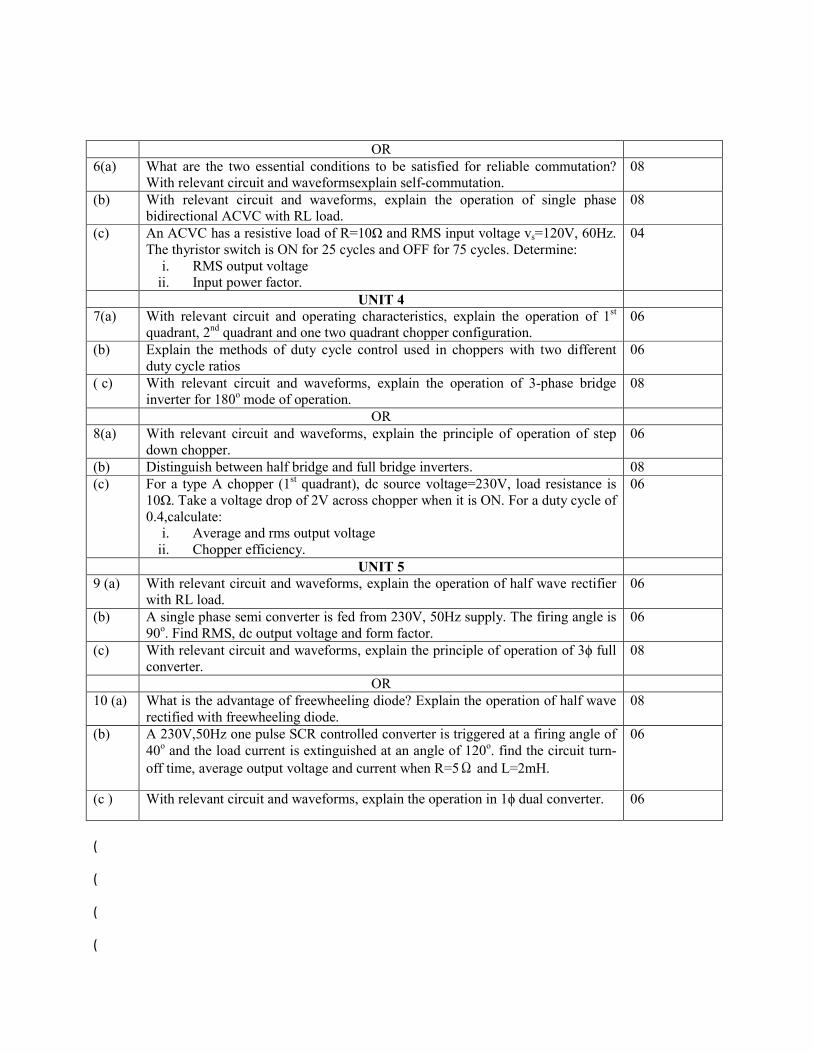
OR 6(a) What are the two essential conditions to be satisfied for reliable commutation? 08

With relevant circuit and waveforms explain self-commutation. (b) With relevant circuit and waveforms, explain the operation of single phase
bidirectional ACVC with RL load. 08
(c) An ACVC has a resistive load of R=10Ω and RMS input voltage vs =120V, 60Hz. The thyristor switch is ON for 25 cycles and OFF for 75 cycles. Determine:
i. RMS output voltage ii. Input power factor.
04
UNIT 4 7(a) With relevant circuit and operating characteristics, explain the operation of 1st
quadrant, 2nd quadrant and one two quadrant chopper configuration. 06
(b) Explain the methods of duty cycle control used in choppers with two different duty cycle ratios
06
( c) With relevant circuit and waveforms, explain the operation of 3-phase bridge inverter for 180o mode of operation.
08
OR 8(a) With relevant circuit and waveforms, explain the principle of operation of step
down chopper. 06
(b) Distinguish between half bridge and full bridge inverters. 08 (c) For a type A chopper (1st quadrant), dc source voltage=230V, load resistance is
10Ω. Take a voltage drop of 2V across chopper when it is ON. For a duty cycle of 0.4,calculate:
i. Average and rms output voltage ii. Chopper efficiency.
06
UNIT 5 9 (a) With relevant circuit and waveforms, explain the operation of half wave rectifier
with RL load. 06
(b) A single phase semi converter is fed from 230V, 50Hz supply. The firing angle is 90o. Find RMS, dc output voltage and form factor.
06
(c) With relevant circuit and waveforms, explain the principle of operation of 3ϕ full converter.
08
OR 10 (a) What is the advantage of freewheeling diode? Explain the operation of half wave
rectified with freewheeling diode. 08
(b) A 230V,50Hz one pulse SCR controlled converter is triggered at a firing angle of 40o and the load current is extinguished at an angle of 120o. find the circuit turn-
off time, average output voltage and current when R=5Ω and L=2mH.
06
(c ) With relevant circuit and waveforms, explain the operation in 1ϕ dual converter. 06
P.E.S. College of Engineering, Mandya - 571 401

(An Autonomous Institution under VTU, Belgaum) Fifth Semester, B.E. – Electrical and Electronics Engineering
Basic Electrical Engineering (P13EE15)
Time: 3 hrs Model Question paper Max. Marks: 100
Q.No. Questions Marks 1. (a)
Calculate the combined resistance of four conductors of 6, 9, 12 and 18Ω connected in parallel. If current flowing in the circuit is 2A, find the current flowing in the 9Ω resistor.
06
(b) Derive an expression for the energy stored in a magnetic field. 06 (c) State and explain faraday’s laws of electromagnetic induction, Lenz’s law,
Fleming’s right hand rule and Fleming left hand rule. 08
OR 2. (a)
State and explain Kirchhoff’s law. 06
(b) An 8 ohm resistor is in series with parallel combination of two resistors 12Ω and
6Ω the current in the 6 Ω resistor is 5A, determine the total power dissipated in the circuit.
06
(c) Two identical coils of 1200 turns each are placed side by side such that, 60% of the flux produced one coil links the other. A current of 10A in the first coil, sets up a flux of 0.12mwb the current the first coil changes from +10A to -10A in 20ms. Find
i. The self-inductance of the coils ii. The emf induced in both the coils.
08
3. (a)
Define RMS value and derive an expression for RMS value of sinusoidally varying AC voltage.
06
(b) How is current of 10A shared by two impedances Z1= 2-j5 Ω, and z2 =
6.708<26.56o Ω
06
(c) Derive an expression for the instantaneous power in a pure capacitor energized by sinusoidal voltage. Draw the wave shapes of voltage, current and power signals involved
08
OR 4. (a)
With a neat sketch briefly explain how an alternating voltage is produced when a coil is rotated in a magnetic field.
06
(b) An inductive coil draws a current of 2A, when connected to a 230V, 50Hz supply. The power taken by the coil is 100W. Calculate the resistance and inductance of the coil.
06
(c) An alternating voltage of e= Emsin is applied across a pure inductor of L H. i. Derive an expression for the resulting current
ii. What is its active power consumption? iii. Draw the phase diagram iv. Show the waveforms of voltage, current and power.
08

5.(a) Obtain the relationship between line voltages and phase voltages in a star connected balanced, 3-phase supply system.
06
(b) Explain the effect of power factor on two wattmeter readings connected to measure the three phase power.
06
(c) With a neat sketch explain the construction and working of a single phase induction type energy water.
08
6(a) What is necessity of earthing? Explain any one type of earthing.. 06 (b) Explain with neat diagram the working of dynamo meter type wattmeter. 06 (c) A star connected load consists of 6 Ω resistances in series with an 8 Ω inductive
reactance in each phase. A supply voltage of 440V at 50Hz is applied to the load. Find the line current power factor and power consumed by the load.
08
7(a) A three phase, 50Hz 16 pole alternator with star connected winding has 144 slots
with 10 conductors per slot. The flux per pole 24.8 mWb is sinusoidally distributed, the coils are full pitched. Find (i) speed (ii) the line emf. Assume winding factor kd = 0.96.
06
(b) Derive an expression for the torque developed in a DC motor. 06 (c) Draw the cross sectional view of DC machine and explain the function of each
part. 08
OR 8(a) Obtain an expression for emf of an alternator and explain the significance of
winding factor. 08
(b) Discuss the different types of rotor construction of alternator mentioning their typical advantages and applications.
06
(c) A 120V DC shunt motor has an armature resistance of 0.2 Ω and shunt field
resistance of 60 Ω. It runs at 1800RPM, when it takes full load current of 40A. Find the speed of the motor while it is operating at half the full load, with load terminal voltage remaining same.
06
9 (a) Explain the principle operation of a single phase transformer and derive its EMF equation.
08
(b) A 3 phase induction motor with 4 poles is supplied from an alternator having 6 poles and running at 10000RPM. Calculate (i) synchronous speed of the induction motor (ii) its speed when slip is 0.04 and (iii) frequency of the rotor emf, when speed is 600RPM.
06
(c) What ate the transformer losses? On what factors do they depend? And how are they minimized.
06
OR 10 (a) Explain the principles of operation of a 3 phase induction motor. 06
(b) Discuss the important features and advantages of squirrel cage and phase wound rotor constructions in an induction motor.
06
(c) A 250KVA, 1ϕ transformer has 98.135% efficiency at full load and 0.8 lagging p.f. the efficiency at half load and 0.8 lagging p.f is 97.751%. Calculate the iron loss and full- load copper loss.
08

P.E.S. College of Engineering, Mandya - 571 401
(An Autonomous Institution under VTU, Belgaum) Fifth Semester, B.E. – Electrical and Electronics Engineering
Power electronics (P15EE51)
Model Question paper
Time: 3 hrs MaxMarks: 100
Q.No. Questions Marks UNIT 1 1. (a)
Mention the various types of power converter systems. Explain any four of them with their circuit, input and output voltage waveforms.
10
(b) Sketch and explain the switching characteristics of a BJT. 06 © What are the peripheral effects of a power electronic converter system? What are
the remedies for them 04
OR 2. (a)
Explain the control characteristics of any four semiconductor devices with the relevant circuit and waveforms.
10
(b) Sketch and explain the switching characteristics of a power MOSFET. 06
(c) Give the comparison between MOSFET and BJT. 04
UNIT 2 3. (a)
What is the need of base drive control? Explain anti saturation and proportional control with their circuit.
08
(b) Explain the static V-I characteristics of a thyristor with their modes of operation. 08 (c) Draw and explain the operation of snubber circuit. 04
OR 4. (a)
What is need of isolation circuits? Explain the two isolation schemes generally used with their circuit.
08
(b) Using the two transistor analogy of a thyristor, explain the switching characteristics of a thyristor.
08
(c) What is the effect of
and
in a thyristor? Explain the methods to overcome
these effects.
04
UNIT 3 5.(a) What do you mean by commutation? With relevant circuit and waveforms,
explain complementary commutation. 08
(b) With relevant circuit and waveforms, explain the operation of ON- OFF control and derive the expression for output voltage.
08
(c) The resonant pulse commutation circuit has C=30μF and L=4μH. The initial capacitor voltage is V0=200V. determine the circuit turn OFF time, if the load current Im is 250 A.
04
OR 6(a) What are the two essential conditions to be satisfied for reliable commutation?
With relevant circuit and waveformsexplain self-commutation. 08
(b) With relevant circuit and waveforms, explain the operation of single phase bidirectional ACVC with RL load.
08
(c) An ACVC has a resistive load of R=10Ω and RMS input voltage vs=120V, 60Hz. The thyristor switch is ON for 25 cycles and OFF for 75 cycles. Determine:
i. RMS output voltage ii. Input power factor.
04
UNIT 4 7(a) With relevant circuit and operating characteristics, explain the operation of 1st
quadrant, 2nd quadrant and one two quadrant chopper configuration. 06
(b) Explain the methods of duty cycle control used in choppers with two different duty cycle ratios
06
( c) With relevant circuit and waveforms, explain the operation of 3-phase bridge inverter for 180o mode of operation.
08
OR 8(a) With relevant circuit and waveforms, explain the principle of operation of step
down chopper. 06
(b) Distinguish between half bridge and full bridge inverters. 08 (c) For a type A chopper (1st quadrant), dc source voltage=230V, load resistance is
10Ω. Take a voltage drop of 2V across chopper when it is ON. For a duty cycle of 0.4,calculate:
i. Average and rms output voltage ii. Chopper efficiency.
06
UNIT 5 9 (a) With relevant circuit and waveforms, explain the operation of half wave rectifier
with RL load. 06
(b) A single phase semi converter is fed from 230V, 50Hz supply. The firing angle is 90o. Find RMS, dc output voltage and form factor.
06
(c) With relevant circuit and waveforms, explain the principle of operation of 3ϕ full converter.
08
OR 10 (a) What is the advantage of freewheeling diode? Explain the operation of half wave
rectified with freewheeling diode. 08
(b) A 230V,50Hz one pulse SCR controlled converter is triggered at a firing angle of 40o and the load current is extinguished at an angle of 120o. find the circuit turn-off time, average output voltage and current when R=5Ω and L=2mH.
06
(c ) With relevant circuit and waveforms, explain the operation in 1ϕ dual converter. 06

P.E.S. College of Engineering, Mandya - 571 401
(An Autonomous Institution under VTU, Belgaum) Fifth Semester, B.E. – Electrical and Electronics Engineering
Utilization of Electrical Power (P15EE561)
Time: 3 hrs Model Question paper Max. Marks: 100
Q.No. Questions Marks 1. (a)
Mention the advantages of Electric heating 4
(b) Describe the construction and working principle of an induction furnace 10 (c) Explain the different types of resistance welding 06
2. (a)
Describe the construction and principle of working of an induction furnace 10
(b) A 20 kW single phase, 220 V resistance oven employs circular nickel chrome wire for its heating elements. If the wire temperature is not to exceed 11700 C and the temperature of the charge is to be 5000 C. Calculate the length and size of wire required. Assume a radiating efficiency of 0.6 and specific resistance of the nickel-chrome 101.6x10⁻⁶ Ω cm .
06
(c) Explain the various methods of resistance welding 04
3. (a)
Explain the law of illumination 06
(b) Define the following: i) Brightness ii)Polar curve iii)MSCP iv) Utilization factor 04 (c) Explain the construction and working principle of mercury vapour lamp 10
4. (a)
A 250 V lamp takes a current 0.8 A it produces a total lux 3260 lumens calculate i) MSCP of the lamp ii) the efficiency of the lamp
04
(b) Explain the following : i) Factory lighting ii) Flood lighting 06 (c) Explain the construction and working principle of fluorescent lamp
10
5.(a) Explain the various types of traction system and mention the advantages and
disadvantages 10
(b) Explain clearly systems of railway electrification 10 6(a) List the requirement of an ideal traction system 06 (b) State the advantages of electric traction over other non electric system of traction 06 (c) What are the merits and demerits of DC system of traction electrification 08 7(a) Draw and explain a typical speed –time curve for an electric train movement 08 (b) Define crest speed , Schedule speed, coefficient of adhesion 06

( c) An electric train is to have acceleration and breaking retardation of 0.8 km/h/s and 3.2 km/h/s respectively. If the ratio of maximum to average speed is 1.3 and time for stop 26 seconds. Find the schedule speed from a run of 1.5 km. Assume simplified trapezoidal speed time curve
06
8(a) Derive an expression for the tractive effort developed by an train unit. 10 (b) Derive an expression for specific energy output on level track using a simplified
speed-time curve 10
9 (a) Discuss briefly desirable properties of traction motors 10 (b) Discuss the suitability of series motors for traction duties with the help of
characteristics curve 10
10 (a) Explain with the help of suitable circuit diagram i) shunt transition ii) bridge
transition applied to a pair of D C traction motors 08
(b) What are the advantages and disadvantages of regenerative breaking as applied to traction
06
(c ) Explain the control of single phase AC series motors 06

P.E.S. College of Engineering, Mandya - 571 401
(An Autonomous Institution under VTU, Belgaum) Fifth Semester, B.E. – Electrical and Electronics Engineering
Electrical Machines-II (P15EE53)
Time: 3 hrs Model Question paper Max. Marks: 100
Q.No. Questions Marks 1. (a)
Explain what is meant by CRITICAL FIELD RESISTANCE in a D.C. Shunt Generator and the method of determining it.
5
(b) With relevant diagrams explain armature reaction in D.C. generators and also explain the measures adopted to reduce its effect.
10
(c) Explain why compensating windings are used in D.C. machines. 05
2. (a)
What is commutation? With neat figures explain the process of commutation in a coil undergoing short circuit.
07
(b) A 8 pole lap connected D.C. shunt generator delivers 240 A at 500 V. The armature has 1408 conductors and there are 160 commutator segments. If the brushes are given a load of 4 segments from the no load neutral axis, estimate the demagnetizing and cross-magnetizing Amp turns per pole.
06
(c) What are inter poles? Explain the uses of inter poles in improving commutation by minimizing sparking.
07
3. (a)
Explain typical electrical and N/Ia characteristics of shunt and series D.C. motor 12
(b) Explain any two methods of speed control of D.C shunt motor 08 4. (a)
Derive an expression for torque in a D.C motor 06
(b) Write a note on Three point starter 08 (c) A 4 pole d.c. shunt motor takes 22 A from 220 V supply. The armature and field
resistances are respectively 0.5 Ω and 100 Ω. The armature is lap-connected with 300 conductors. If the flux/pole is 20 mwb. Calculate the speed and the developed torque
06
5.(a) Explain how the efficiency of a series motor can be computed by conducting Field
test 12
(b) A retardation test is carried out on a 1000 rpm D.C. machine. The time taken for
the speed to fall from 1030 rpm to 970 rpm is
A) 36 seconds with no excitation B) 15 seconds with full excitation C) 9
seconds with full excitation and armature supplying an extra load of 10 A at 219
V. Calculate:
08

i) Moment of inertia of armature in kg-m2 ii) Iron losses
iii) The mechanical losses at the mean speed of 1000 rpm 6(a) Explain with a circuit diagram how efficiency can be determined for D.C.
machines by Hopkinson test. 07
(b) Write short note on permanent magnet D.C. Motor. 06 (c) A 500V, D.C. Shunt motor running on No-load takes 5 A. Armature resistances is
0.5 Ω. And shunt field resistance is 250 Ω. Find the output in kW and efficiency of the motor when running on full load and taking a current of 50 A.
07
7(a) Distinguish clearly between salient pole rotor and cylindrical rotor of synchronous
generator. 08
(b) . A 3-phase 6000 V alternator has the following OCC at Normal speed.
Field Amperes 14 18 23 30 43
TERMINAL VOLTS (LINE VALUE)
4000 5000 6000 7000 8000
With armature short circuited and full load current flowing the field current is 17 A and when the machine is supplying full load of 200 kVA at zero power factor, the field current is 42.5 A and the terminal voltage is 6000 V. Determine the field current required when the machine is supplying full load 0.8 pf lag by Zpf method.
12
8(a) Derive the emf equation of a synchronous generator taking into consideration the
pitch factor and breadth factor 06
(b) Describe the synchronous Impedance method to determine regulation of an alternator for lagging and leading power factor.
08
(c) Calculate the no-load terminal voltage of a 3 phase, 8 pole ster-connected alternator running at 750 rpm, having the following data: Flux/pole = 55 mwb, number of slots = 72, number of conductors/slot = 10, coil span = 160° electrical.
06
9 (a) What are the conditions to be satisfied for a successful parallel operation of alternators?
04
(b) Explain with necessary circuit diagram how Xd and Xq of an alternator is determined experimentally.
08
(c) An alternator is supplying constant load. With suitable vector diagrams explain the effect of variations on excitation on armature current and power factor.
08
10 (a) Write Explanatory notes on the following topics.
Hunting in Synchronous machines. ii) V-curves and inverted V-curves of
Synchronous motor. iii) Synchronization of alternator with bus bar
15
(b) A 6.6 kV 3 phase star connected synchronous motor takes a line current of 50 A. The effective resistance and reactance per phase are respectively 1.5 Ω and 8 Ω. Find: i) The power supplied to the motor ii) The induced emf for p.f. of 0.8 lead.
05

P.E.S. College of Engineering, Mandya - 571 401 (An Autonomous Institution affiliated to VTU, Belgaum)
Third Semester, B.E. – Electrical and Electronics Engineering Semester End Examination; Dec 2018/Jan 2019.
P17EE32 Network Analysis Time: 3 hrs MODEL QUESTION PAPER Max. Marks: 100
Note: Answer FIVE full questions, selecting ONE full question from each unit.
SI. No Questions Marks Unit-I 1.a) Write a brief note on Dependent and Independent Sources.Write their representations in
an electrical circuit. 04
b) Determine the mode voltages with respect to the reference node, voltages V1 and V2 and
the voltage V12 across nodes 1 and 2, using nodal analysis for circuit Fig. Q 1(b).
Fig. Q 1(b).
08
c) For the network shown in fig. Q 1(c) solve for the loop currents I1 and I2 using mesh
analysis and determine the voltage across the inductor j 10.
fig. Q 1(c)
08
OR 2.a) Using superposition principle, find the current in 6 ohm resistor in the network shown in
Fig.Q 2(a)
Fig.2(a)
10
b) State Thevenin’s theorem and obtain the current through 1 resistor connected across
AB of the network shown in Fig.Q 2(b) using Thevenin’s theorem.
10

Fig. Q 2(b)
Unit-II 3.a) Find the maximum possible number of trees for the network shown in Fig. Q 3(a)
Fig.Q 3(a)
05
b) Write a note on complete and reduced incidence matrix 05 c) For the network shown in Fig.Q 3(c) calculate I1, I2, I3 using graph theory and network
equilibrium equation based on KVL
Fig.Q 3(c)
10
OR 4.a) What are the Dirichlets conditions? Write a note on Waveform symmetry. 06 b) Obtain the trigonometric fourier series for a half wave rectified sine wave. 06 c) A series RL circuit consists of a resistance of 5 ohm and inductance of 0.02 H is
connected across the voltage of V = (100+50 sin100t=25 sin 150t) volts.Find the (1) current (ii) Average power (iii) power factor.Also write the expression for the current in the circuit.
08
Unit-III 5.a) For the circuit shown in Fig.Q 5(a) steady state is reached with switch K open. Switch K
is opened at t = 0. Determine the values of i1, i2,
1di
dt and
2di
dt all at t = 0+. Also find 2
12
d i
dt &
22
2
d i
dt at t = 0+.
10

Fig.Q 5(a)
b) For the network shown in Fig.Q 5(b) switch K is closed at t = 0. Find the values
i) V1 & V2 at t =0+ ii) V1 & V2 at t = ii)
1dv
dt &
2dv
dt at t = 0+
iii)
21
2
d v
dt at t = 0+
Fig.Q 5(b)
10
OR 6.a) Show that Laplace transform of (t) = 1 04
b) Find the Laplace transform of the wave form shown in Fig.Q 6(b). 06 c) Find the Laplace transform of the periodic wave form shown, in Fig.Q 6(c).by waveform
synthesis.
Fig.Q 6(b). Fig.Q 6(c)
10
Unit-IV 7.a) For the circuit given in Fig.Q 7(a), the switch is opened at t = 0. Determine the terminal
voltage ( )a t
using Laplace Transformation method.
Fig.Q 7(a)
10
b) In the two circuits shown in Fig.Q 7(b) v1(t) = sin 103t and v2(t) = e-1000t and c = 1 F. Determine the values of R and L to satisfy i1(t) = i2(t)
Fig.Q 7(b)
10

OR 8.a) A series RL circuit is excited by a source V(t) = 4e –3t with R = 2 & L = 1 H. Find an
expression for the voltage across the inductor VL(t) by using convolution theorem 10
b) A pulse is of amplitude 5V for duration of 4 sec with its starting point t = 0, Find the convolution of this pulse with itself and draw the convolution versus time.
10
Unit-V 9.a) For the network shown in Fig. Q.9 (a), Obtain driving point impedance function.
Fig. Q.9 (a)
10
b) For the network shown in Fig. Q.9 (b), Obtain Z and Y parameters.
Fig. Q.9 (b)
10
OR 10.a) A 3-Phase, 440v mesh connected system has the loads as follows. The voltage coils are
connected between R&Y and B&Y Branch RY > 20Kw at UPF Branch YB > 30KvA at 0.8 PF Lagging Branch BR > 20KvA at 0.6 PF lead.
Find the line currents and readings of Watt meters whose current coils are in phases R&B.
10
b) A system of 3 phase symmetrical voltages of value 200v is connected to a delta connected balanced 0.8 PF induction motor load of 6Kw across the terminals ABC. A 4Kw UPF load is connected across AB. The phase sequence is ACB. Find the two watt meter readings which are connected such that their current coils are in line A & C with the potential coils connected to B.
10

P17EE43 Page No... 1
P.E.S. College of Engineering, Mandya - 571 401
(An Autonomous Institution affiliated to VTU, Belagavi) Fourth Semester, B.E. - Electrical and Electronics Engineering
Model question paper Electrical Machines - I
Time: 3 hrs Max. Marks: 100
Note: Answer FIVE full questions, selecting ONE full question from each unit.
UNIT - I
1 a. Explain the construction of shell and core type single phase transformer. 6
b. Explain the concepts of transformer on load with suitable vector diagram for leading power factor. 6
c. A 33 kVA, 2200/200 V 50 Hz single phase transformer has the following parameters :
Primary winding: R1 = 2.4 and X1 = 6 ; Secondary winding: R2 = 0.03 and X2 = 0.07 .
Find; i) Primary resistance and Leakage accountancy referred to secondary
ii) Secondary resistance and Leakage reactance referred to primary
iii) Equivalent resistance and Equivalent reactance referred to both primary and secondary
iv) Full load ohmic loss.
8
2 a. Derive an expression for copper saving in an auto transformer as compared to two winding
transformer. 6
b. With a neat diagram, explain the construction and working of constant voltage transformer. 6
c. A single phase transformer 3300/400 V has the following details :
R1 = 0.75 , X1 = 3.6 , R2 = 0.011 and X2 = 0.045 .
The secondary winding is connected to a coil having resistance of 4.5 and Inductive resistance
of 3.2 . Calculate the secondary terminal voltage and the power consumed by the coil.
8
UNIT - II
3 a. Derive an expression for regulation of a transformer for lagging power factor. 6
b. A transformer has its maximum efficiency of 0.98 at 15 kVA, UPF. During a day it is loaded as;
i) 12 hr : 2 kW at 0.5 PF lag ii) 06 hr: 12 kW at 0.8 PF lag iii) 06 hr: 18 kW at 0.9 PF lag
Find its all day efficiency.
8
c. Two single phase transformer share a load of 400 kVA at 0.8 PF lag. Their equivalent impedances
referred to secondary winding are (1+J2.5) and (1.5+J3) respectively. Calculate the load shared
by each transformer.
6
4 a. With neat circuit diagram, explain regenerative test for determining the efficiency of a transformer. 6
b. A 10 kVA , 2500/250 V, single phase transformer have the following test results :
OC test: 250 V, 0.8 A, 50 W; SC test: 60 V, 3 A, 45 W; Calculate;
i) Efficiency at 75% and 125% of FL at 0.8 PF lag
ii) The load at which maximum efficiency occurs and also the value of efficiency @ 0.8 PF
iii) Regulation and secondary terminal voltage under rated load at 0.8 PF lag and 0.8 PF lead
8
U.S.N
Contd…2

P17EE43 Page No... 2 c. Show the condition at which efficiency of transformer is maximum? 6
UNIT - III
5 a. With the help of circuit and Phasor diagram, explain how 2-phase supply can be obtained from
3-phase supply using Scott connection? 12
b. Show that open delta communication has a kVA rating of 58% of rating of the normal delta-delta
connection. 8
6 a. A single phase 3 winding transformer have the following results from three short circuit test :
Secondary shorted, primary exited : 125 V, 25 A, 700 W
Tertiary shorted, primary excited : 130 V, 25 A, 800 W
Tertiary shorted, Secondary excited : 30 V, 120 A, 830 W
The ratings of winding are as follows :
Primary 100 kVA, 3300 V; Secondary 50 kVA, 1100 V; Tertiary 50 kVA, 400 V.
Find the resistances and leakage reactance of star equivalent circuit.
12
b. List out the advantages of three phase transformer. 4
c. Mention the conditions to be satisfied for parallel connection of 3-phase transformers. 4
UNIT - IV
7 a. With suitable sketches, explain the construction of squirrel cage and slipping induction motor. 8
b. Derive an expression for torque developed by an induction motor. 6
c. A 24 pole 50 Hz star connected IM has rotor resistance of 0.016 per phase and rotor reactance of
0.265 per phase at stand still. It is achieving its full load torque at a speed of 247 rpm. Calculate
the ratio of, i) Full load torque to maximum torque ii) Starting torque to maximum torque.
6
8 a. With relevant sketches, explain the concepts of rotating magnetic field in 3-phase induction motor. 8
b. With neat circuit, explain the working of star-delta starter. 6
c. An 18650 W, 4 pole, 50 Hz, 3 phase IM has friction and windage loses of 2.5% of the output. The
full load slip is 4% compute for full load, i) Rotor Cu loss ii) Rotor input iii) Shaft torque. 6
UNIT - V
9 a. Draw the circuit diagram of a 20 HP, 50 Hz, 3 phase star connected IM with the following data :
No load test : 400 V, 9 A, 0.2 PF lagging; Blocked rotor test: 200 V, 50 A, 0.4 PF lagging
Determine the line current and efficiency for full load condition from the circle diagram.
(Choose the scale of 1 cm = 5 A).
12
b. With neat circuit and phase diagram, explain the working of capacitor start IM. Also sketch torque-
speed characteristics. 8
10 a. Explain the principle of operation of a single phase IM using double revolving field theory. 10
b. Write a short note on :
i) Split phase induction motor
ii) Cogging and Crawling in induction motor
6
4
* * * *

Code: P15EE71 P a g e . . . 1
P.E.S. College of Engineering, Mandya - 571 401 (An Autonomous Institution affiliated to VTU, Belgaum)
Seventh Semester, B.E. – Electrical and Electronics Engineering Semester End Examination Dec.2018/Jan - 2019
Computer Techniques in Power System Analysis Subject code: P15EE71
Time: 3 hrs MODEL QUESTION PAPER Max. Marks: 100
Note: Answer FIVE full questions, selecting ONE full question from each unit.
UNIT - I
1(a) With a neat sketch define (i) Tree and co-tree (ii) Branch and link (iii) Basic loops and Basic cut sets.
08
(b) Explain the significance of primitive network and hence get the performance equations in both impedance and admittance form.
06
(c) The bus incidence matrix A, of 8-elements, 5-node system is given below. Obtain the element node incidence matrix and the oriented graph. The columns represent elements and the rows represent buses.
1 0 0 0 -1 0 1 0 0 0 1 0 0 -1 0 1 0 0 1 1 0 0 0 1 0 0 -1 0
06
2(a) Define (i) branch-path incidence matrix, (ii) basic loop incidence matrix , and (iii) Performance equations in both impedance and admittance form for primitive networks.
06
(b) The terminal nodes of the elements of a 5 – nodes graph, having 8- elements are as in the table given below. Each element is oriented from node ‘p’ to node ‘q’. Draw the graph and find the matrices Ậ, A, B, C & K.
Element No. 1 2 3 4 5 6 7 8
From node ‘p’ 1 1 1 3 2 4 3 2
To node ‘q’ 2 3 4 5 3 5 4 5
08
(c) For the above obtained graph and incidence matrices, verify the relations: (i) AbK
t = U, (ii) Cb= -Blt.
06
UNIT - II
3(a) Derive the expression for the bus admittance matrix, Ybus using singular transformation technique.
06
(b) Determine the bus admittance matrix Ybus using the singular transformation method for the sample power system who’s the line data is as shown in table below. Verify the result by inspection method.
Line No. 1 2 3 4 5 Bus-code (p-q) 0 - 1 1 - 2 2 -3 3 - 0 2 – 0 Impedance p.u 0.8 0.5 0.4 0.5 0.25
08
(c) Obtain the equivalent circuit of the tap changing transformer having the off-nominal turns ratio, a.
06
4.(a) Explain the modification for the formation of Ybus , when a line is having a tap changing transformer at any one end.
06

Code: P15EE71 P a g e . . . 2
.(b) In the network shown below in figure 4(b), the series reactances of the lines are marked in p.u. By selecting the node (1) as reference node, obtain bus admittance matrix by singular transformation technique. Verify the result by inspection method.
Figure.4(b)
08
(c) Explain the steps to modify the ZBUS for the removal of a line or modification of the line impedance.
06
UNIT - III
5(a) What are different types of buses considered during power system load flow analysis? Explain briefly.
05
(b) Determine the voltages at the end of first iteration using Gauss-Seidal method for the system data given below. Assume an acceleration factor of 1.6. (i) Line Data
Bus Code 1 - 2 1 - 3 2 - 3 2 - 4 3 - 4 Admittance 2 – j 8 1 – j 4 0.66– j0.664 1 – j 4 2 – j 8
(ii) Bus Data
Bus No. P Q V Remarks 1 - - 1.06|_0 SLACK 2 0.5 0.2 1+ j 0 PQ 3 0.4 0.3 1+ j 0 PQ 4 0.3 0.1 1+ j 0 PQ
15
6(a) Derive the expression in polar form for the typical diagonal elements of the sub matrices of the Jacobian in the Newton Raphson method of load flow analysis.
08
(b) Write notes on Fast decoupled load flow analysis 06 (c) Compare NR and GS method LFS procedure in respect of the followings:
(i) Time per iteration (ii) Total solution time. (iii) Acceleration of convergence of iterative solution.
06
UNIT - IV
7(a) Explain the input – out curves and other performance curves of thermal plant. 04 (b) Explain and derive the necessary condition for Economic operation of generators with
transmission loss considered. 08
(c) The fuel costs per hour for plants 1 and 2 are given by: F1 = 0.2 P12+40 P1 + 120 Rs./Hr. F2 = 0.25 P22+ 30P2 + 150 Rs./Hr. Determine the economic operating schedule and the corresponding cost of generation if the maximum and minimum loading on each unit is 100 MW and 25 MW, the demand is 180 MW and the transmission losses are neglected. If the load is equally shared by both the units, determine the saving obtained by loading the units as per equal incremental production cost.
08
8(a) What are transmission line coefficients? Obtain the general loss coefficient formula with usual notations.
10

Code: P15EE71 P a g e . . . 3
b) A two bus system is shown in the fig.8 (b). If the load of the125 MW is transmitted from plant 1 to the load, a loss of 15.65MW is incurred. Determine the generation schedule and the load demand if the cost of received power is Rs. 24/MW-hr. Solve the problem using co-ordination equations and penalty factor method approach. The incremental production costs of the plants are: (dF1/dP1) = 0.025P1 +15. (dF2/dP2) = 0.05P2 +20.
Figure.8.(b)
10
UNIT - V
9(a) Explain the point by point method of solving the swing equation.
10
(b) With the help of a flow chart and equation explain the transient stability analysis using Modified Euler’s method.
10
10(a) Explain Runge -Kutta method for the solution of Swing equation.
10
10(b) Explain Milne’s Predictor Corrector method of solving the differential equation.
10

Model Question paper
P15EE743 : Testing and commissioning of Electrical Equipments
Time: 3 hrs Max. Marks: 100
Note: i) Answer FIVE full questions, selecting ONE full question from each Unit.
ii) Assume suitable missing data if any.
UNIT-I
Q.No. Questions Marks CO Blooms level
1. (a)
Explain the various accessories and fitments of
power transformer
10 CO1 L2
(b) What is drying out of transformer . Explain different
methods of drying out of a transformer
10 CO1 L2
OR
2. (a)
State the various commissioning test on power transformer
10 CO1 L2
(b) Explain impulse testing on transformer 10 CO1 L2
UNIT-II
3. (a)
List the steps involved in Installation of an alternator
05 CO2 L2
(b) Explain the procedure of drying out of synchronous machines
05 CO2 L2
(c) Explain different methods of cooling of turbo generator
10 L2
OR
4. (a)
Explain the sudden 3 phase short circuit test on generator
05 CO2 L2
(b) Explain the open circuit test on synchronous generator
05 CO2 L2
(c) Explain the procedure of measurement of dc resistance of windings in alternator
10 CO2 L2
UNIT-III 5.(a) What are the information to be given with enquiry
and placing the order for induction motor
10 CO3 L1
(b) Explain the foundation details used for induction motor
10 CO3 L2
OR 6(a) What are the different methods of drying out of an 10 CO3 L2

induction motor ? Explain. (b) How temperature test is carried out in induction
motor
05 CO3 L1
(c) Explain blocked rotor test on induction motor 05 CO3 L2 UNIT-IV
7(a) List the different test to be conducted on a circuit
breaker
10 CO4 L1
(b) Explain different routine test conducted on CTs 05 CO4 L2 ( c) How mechanical test is conducted on circuit breaker 05 CO4 L1
OR 8(a) Mention the possible troubles, causes and corrective
actions for out door circuit breaker
10 CO4 L1
(b) List the specifications of high voltage circuit breaker 05 CO4 L2 ( c) Enumerate type test conducted on CTs 05 CO4 L3
UNIT-V 9 (a) State the seven principles of safety management 10 CO5 L2
(b) Explain the safety management interface with O and
M
10 CO5 L2
OR 10 (a) Mention the Recommend safety precautions against
electrical shock in small building, shops and LV
stations.
10 CO5 L2
(b) State and explain the principles of live line working 10 CO5 L2

PES COLLEGE OF ENGINEERING, MANDYA-571401 (An Autonomous Institution under VTU, Belgaum)
VIII Semester B.E(ELECTRICAL & ELECTRONICS ENGG) Course with code: ENERGY AUDITING & DEMAND SIDE MANAGEMENT (P15EE821)
MODEL QUESTION PAPER
Time: 3Hrs Max marks. 100
Q.No. Questions Marks C O
Blooms level
1.a) Discuss the energy scenario in the world and in India. 12 CO1 L2 b) Which are the issues addressed by Energy conservation Act? 08 CO1 L1
OR 2.a) What is time value of money concept? What are the different cash-flow
models? 04 CO1 L1
b) What is ABT? What are the broad features of ABT design? 08 CO1 L1 c) Calculate the depreciation rate using the (i) Straight-line, (ii) Sum-of-years
digit and Salvage is Rs.0 Life of the equipment, n = 5years Initial expenditure p = Rs. 150000
For declining balance use a 200% rate.
08 CO1 L3
3.a) Define energy audit. Explain the importance of energy audit in industry. 7 CO2 L1 b) Explain the detailed energy audit activities. 5 CO2 L2 c) Explain the different steps of presenting the energy audit results. 8 CO2 L2
OR 4.a) Give the 10 methodology steps for detailed energy auditing explain 10 CO2 L1
b) What is energy use profile? What are the audits required for constructing the energy use profile?
10 CO2 L1
5.a) Derive an expression for most economical power factor considering constant active Power. Draw relevant Vector diagram.
10 CO3 L3
b) A 3- phase, 50 Hz, 400 V motor develops 200 H.P (149.2 kW) the power
factor being 0.75 lagging and efficiency 90%. A bank of capacitors is
connected in delta across the supply terminals and power factor raised to
0.95 lagging. Each of the capacitance units is built of 4 similar 100 V
capacitors; determine the capacitance of each capacitor.
10 CO3 L3
OR
6.a) Explain the calculation of power factor correction. 8 CO3 L2 b) An alternator in supplying a load of 300KW at a p.f. of 0.6 lagging. If the
power factor is raised to Unity, how many more KW can the alternator Supply for the same KVA loading?
6 CO3 L3
c) Write a note on energy efficient motors. 6 CO3 L2 7.a) What is DSM? What is scope of DSM? How did the concept of DSM
evolve? 10 CO4 L1
b) Explain the various steps in DSM planning and implementation. 10 CO4 L2 OR

8.a) Discuss tariff options for DSM. Which tariffs promote DSM? 10 CO4 L3 b) Explain peak clipping, valley filling and strategic energy conservation 10 CO4 L2
9.a) Explain the load management as DSM strategy. 12 CO5 L2 b) With a flow chart, explain corporate level organization of energy
Conservation programme.
08 CO5 L3
OR 10.a) Explain energy conservation opportunities in Agriculture sector &
Illumination sector. 10 CO5 L2
b) With a flow chart, explain Plant level and Division level organization of energy Conservation programme.
10 CO5 L3

Model Question paper
P15EE842 : Utilization of Electrical Power
Time: 3 hrs Max. Marks: 100
Note: i) Answer FIVE full questions, selecting ONE full question from each Unit.
ii) Assume suitable missing data if any.
UNIT-I
Q.No. Questions Marks CO Blooms level
1. (a)
Mention the advantages of Electric heating 4 CO1 L1
(b) Describe the construction and working principle of an induction furnace
10 CO1 L3
(c) Explain the different types of resistance welding 06
OR
2. (a)
Describe the construction and principle of working of an induction furnace
10 CO1 L3
(b) A 20 kW single phase, 220 V resistance oven
employs circular nickel chrome wire for its heating
elements. If the wire temperature is not to exceed
11700 C and the temperature of the charge is to be
5000 C. Calculate the length and size of wire
required. Assume a radiating efficiency of 0.6 and
specific resistance of the nickel-chrome 101.6x10⁻⁶
Ω cm .
06 CO1 L3
(c) Explain the various methods of resistance welding 04 CO1 L2
UNIT-II
3. (a)
Explain the law of illumination 06 CO2 L2
(b) Define the following: i) Brightness ii)Polar curve iii)MSCP iv) Utilization factor
04 CO2 L1
(c) Explain the construction and working principle of
Sodium lamp
10 CO2 L2
OR 4. (a)
A 250 V lamp takes a current 0.8 A it produces a total lux 3260 lumens calculate i) MSCP of the lamp ii) the efficiency of the lamp
04 CO2 L3
(b) Explain the following : i) Factory lighting ii) Flood lighting
06 CO2 L2
(c) Explain the construction and working principle of 10 CO2 L2

fluorescent lamp
UNIT-III 5.(a) Explain the various types of traction system and
mention the advantages and disadvantages 10 CO3 L2
(b) Explain clearly systems of railway electrification 10 L2
OR 6(a) List the requirement of an ideal traction system 06 CO3 L1 (b) State the advantages of electric traction over other
non electric system of traction 06 CO3 L1
(c) What are the merits and demerits of DC system of traction electrification
08 CO3 L1
UNIT-IV 7(a) Draw and explain a typical speed –time curve for an
electric train movement 08 CO4 L3
(b) Define crest speed , Schedule speed, coefficient of adhesion
06 CO4
( c) An electric train is to have acceleration and breaking retardation of 0.8 km/h/s and 3.2 km/h/s respectively. If the ratio of maximum to average speed is 1.3 and time for stop 26 seconds. Find the schedule speed from a run of 1.5 km. Assume simplified trapezoidal speed time curve
06 CO4 L3
OR 8(a) Derive an expression for the tractive effort
developed by an train unit. 10 CO4 L4
(b) Derive an expression for specific energy output on level track using a simplified speed-time curve
10 CO4 L4
UNIT-V 9 (a) Discuss briefly desirable properties of traction
motors 10 CO5 L3
(b) Discuss the suitability of series motors for traction duties with the help of characteristics curve
10 CO5 L3
OR 10 (a) Explain with the help of suitable circuit diagram i)
shunt transition ii) bridge transition applied to a pair of D C traction motors
08 CO5 L2
(b) What are the advantages and disadvantages of
regenerative breaking as applied to traction
06 CO5 L1
(c ) Explain the control of single phase AC series motors 06 CO5 L2

P18EE15 Page No... 1
P.E.S. College of Engineering, Mandya - 571 401
(An Autonomous Institution affiliated to VTU, Belagavi)
First Semester, B.E. –Model Question Paper Basic Electrical Engineering
(Common to All Branches) Time: 3 hrs Max. Marks: 100
Note: Answer FIVE full questions, selecting ONE full question from each unit.
UNIT - I
1 a. Define RMS value and derive an expression for RMS value of sinusoidally varying alternating
voltage. 6
b. Derive an expression for Instantaneous power in an RC series circuit. Draw the related
waveforms and vector diagrams. 8
c. A circuit having resistance of 12 , an Inductance of 0.15 H and a capacitance of 100 µF in
series is connected across 100 V, 50 Hz supply. Calculate the impedance, current and the
phase angle between voltage and current.
6
2 a. Define Average value and derive an expression for Average value of sinusoidally varying
alternating current. 6
b. Derive an expression for Instantaneous power in an RL series circuit. Draw the related
waveforms and vector diagram.
8
c. A resistance of 100 is connected in series with 100 µF across a 230 V, 60 Hz. Find the
Impedance, current, power factor, power voltage across resistor and voltage across capacitor in
the circuit
6
UNIT - II
3 a. Obtain a relationship between line voltages and phase voltages in star connected balanced
3-phase system. 6
b. What is earthing ? with neat sketch explain the consturction of plate earthing. 8
c. With neat diagrams and waveforms, explain the generation of three phase voltage. 6
4 a. With neat circuit and switching table, explain two-way of three way control of lamps. 6
b. A balanced star connected load of (8+J6) per phase is connected to a three phase, 230 V
supply. Find the line current, power factor, power and reactive power. 6
c. With a neat sketch explain the construction and working of a single phase induction type
energy meter. 8
UNIT - III
5 a. Draw the cross sectional view of DC machine. Explain the construction and function of each
part. 8
b. Obtain an expression for EMF of a synchronous generator. 6
c. A 3, 6 pole star connected alternator has 48 slots and 12 conductors per slot on the armature,
if the rotor rotates at 1200 rpm and the flux per pole is 0.3 Wb. Calculate the EMF Induced in
the armature. The coils are full pitched and the winding factor is 0.95.
6
6 a. Derive an expression for torque developed in a DC motor. 6
b. A 4 pole, 220 V, lap connected dc shunt motor has 36 slots, each slot containing 8
U.S.N
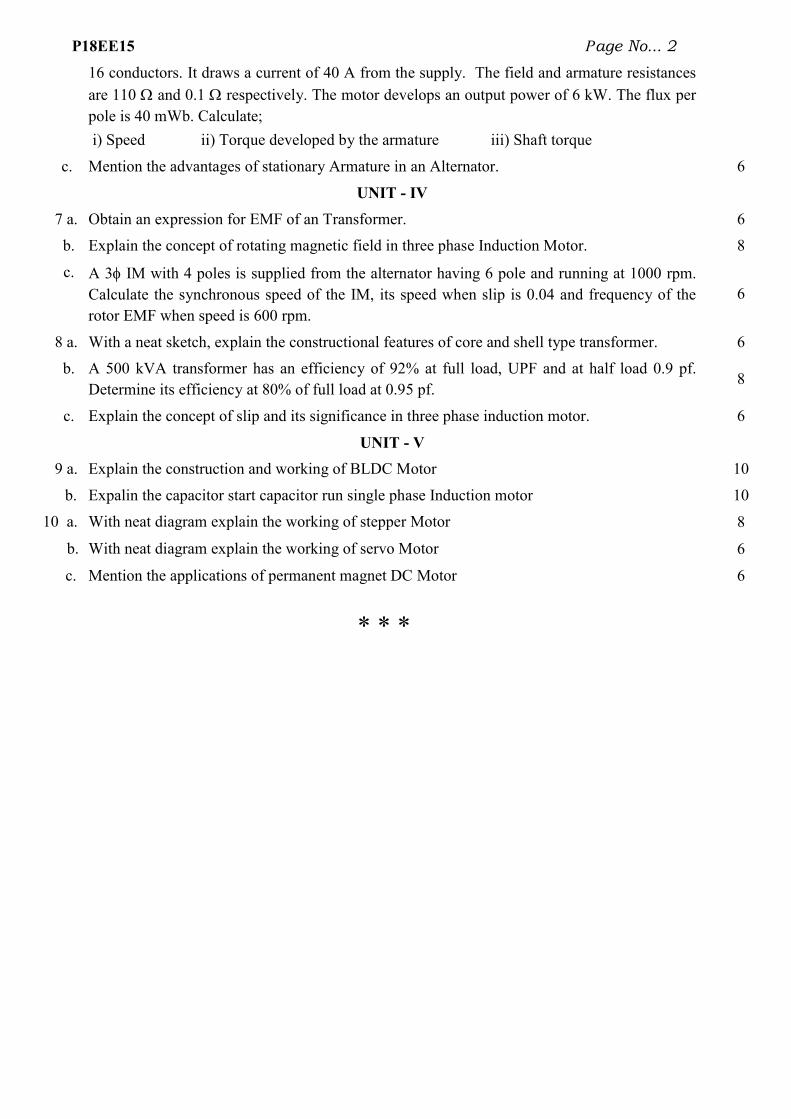
P18EE15 Page No... 2
16 conductors. It draws a current of 40 A from the supply. The field and armature resistances
are 110 and 0.1 respectively. The motor develops an output power of 6 kW. The flux per
pole is 40 mWb. Calculate;
i) Speed ii) Torque developed by the armature iii) Shaft torque
c. Mention the advantages of stationary Armature in an Alternator. 6
UNIT - IV
7 a. Obtain an expression for EMF of an Transformer. 6
b. Explain the concept of rotating magnetic field in three phase Induction Motor. 8
c. A 3 IM with 4 poles is supplied from the alternator having 6 pole and running at 1000 rpm.
Calculate the synchronous speed of the IM, its speed when slip is 0.04 and frequency of the
rotor EMF when speed is 600 rpm.
6
8 a. With a neat sketch, explain the constructional features of core and shell type transformer. 6
b. A 500 kVA transformer has an efficiency of 92% at full load, UPF and at half load 0.9 pf.
Determine its efficiency at 80% of full load at 0.95 pf. 8
c. Explain the concept of slip and its significance in three phase induction motor. 6
UNIT - V
9 a. Explain the construction and working of BLDC Motor 10
b. Expalin the capacitor start capacitor run single phase Induction motor 10
10 a. With neat diagram explain the working of stepper Motor 8
b. With neat diagram explain the working of servo Motor 6
c. Mention the applications of permanent magnet DC Motor 6
* * *

Course Title: Power Plant Engineering Course Code: P15EE751
Model Question Paper Marks Blooms
level
COs
UNIT – I
1. a. Write a brief note on site selection and classification of the site for hydroelectric power generation. 10 L1 CO1
b. Explain main components of different types of hydroelectric power
plants. 10 L2 CO1
2 a. Explain the main parts of steam power plant. 10 L2 CO1
b. Explain the coal handling and ash disposal schemes for thermal power
plant. 10 L2 CO1
UNIT – II
3 a. Write a brief note on site selection nuclear power station and Explain
main components of reactors of the nuclear power plants. 10 L1 CO2
b. With a neat diagram, explain boiling water reactor (BWR) and
pressurized water reactor (PWR). 10 L2 CO2
4 a. What are the types of diesel plants? Explain the components of diesel
electric station. 10 L2 CO2
b. Write a brief note on choice & characteristic of the diesel station. 10 L1 CO2
UNIT – III
5 a. With a neat schematic diagram, write a note on solar power plant. 10 L1 CO3
b. List out & explain the components of wind power plant. 10 L1 CO3
6. a What are the different schemes for harnessing tidal energy? 10 L2 CO3
b. What are all the common factors which are normally used in electricity
system planning, operation and management? 10 L2 CO3
UNIT – IV
7 a. Explain diversity factor and plant capacity factor. 10 L2 CO4
b. What are the several measures by which low power factor can be
avoided? 10 L2 CO4
8 a. Explain two ways of improving power factor. 10 L2 CO4
b. What do you understand by electrical tariff? Discuss two and three part
tariff and power factor tariff. 10 L2 CO4
UNIT – V
9 a. What are the main neutral grounding practices? 10 L2 CO5
b. Explain the resistant grounding system and obtain an expression for
screening coefficient for n electrodes. 10 L2 CO5
10 a. What is neutral grounding? What are the advantages of neutral ground-
ing? 10 L2 CO5
b. Define resonant grounding. With a neat phasor diagram, explain 3-phase
isolated neutral system. 10 L2 CO5

Course Title: Power Plant Engineering Course Code: P17EE46
Model Question Paper Marks Blooms
level
COs
UNIT – I
1. a. Write a brief note on site selection and classification of the site for hydroelectric power generation. 10 L1 CO1
b. Explain main components of different types of hydroelectric power
plants. 10 L2 CO1
2 a. Explain the main parts of steam power plant. 10 L2 CO1
b. Explain the coal handling and ash disposal schemes for thermal power
plant. 10 L2 CO1
UNIT – II
3 a. Write a brief note on site selection nuclear power station and Explain
main components of reactors of the nuclear power plants. 10 L1 CO2
b. With a neat diagram, explain boiling water reactor (BWR) and
pressurized water reactor (PWR). 10 L2 CO2
4 a. What are the types of diesel plants? Explain the components of diesel
electric station. 10 L2 CO2
b. Write a brief note on choice & characteristic of the diesel station. 10 L1 CO2
UNIT – III
5 a. With a neat schematic diagram, write a note on solar power plant. 10 L1 CO3
b. List out & explain the components of wind power plant. 10 L1 CO3
6. a What are the different schemes for harnessing tidal energy? 10 L2 CO3
b. What are all the common factors which are normally used in electricity
system planning, operation and management? 10 L2 CO3
UNIT – IV
7 a. Explain diversity factor and plant capacity factor. 10 L2 CO4
b. What are the several measures by which low power factor can be
avoided? 10 L2 CO4
8 a. Explain two ways of improving power factor. 10 L2 CO4
b. What do you understand by electrical tariff? Discuss two and three part
tariff and power factor tariff. 10 L2 CO4
UNIT – V
9 a. What are the main neutral grounding practices? 10 L2 CO5
b. Explain the resistant grounding system and obtain an expression for
screening coefficient for n electrodes. 10 L2 CO5
10 a. What is neutral grounding? What are the advantages of neutral ground-
ing? 10 L2 CO5
b. Define resonant grounding. With a neat phasor diagram, explain 3-phase
isolated neutral system. 10 L2 CO5

P15EE833 Page No... 1
P.E.S. College of Engineering, Mandya - 571 401
(An Autonomous Institution affiliated to VTU, Belgaum) Eight Semester, B.E. - Electrical and Electronics Engineering
Power system operation & control – P15EE833 Model Paper
Time: 3 hrs Max. Marks: 100
Sl.No. Model Questions Marks Unit-I
1.(a) What is Energy Control Centre (ECC)? Discuss the functions of ECC.
07
.(b) Explain with a neat block diagram the digital computer configuration for the SCADA systems.
08
.(c) What is Area control error (ACE)? Give the expression for ACE. Explain how ACE (error) can be reduced?
05
2.(a) Derive the expression for the tie line power flow and frequency deviation for two area system.
07
.(b) Explain parallel operation of generators for AGC, with relevant droop characteristic graphs. 08
.(c) Two areas A & D are inter-connected by a tie line. The generating capacity of area ‘A’ is 36,000MW and its regulating characteristic is 1.5% of capacity per 0.1 Hz. Area ‘D’, has a generating capacity of 4,000 MW and its regulating characteristic is 1% of capacity per 0.1 Hz. Find the each area’s share of +400 MW disturbance (load increase) occurring in area ‘D’ and the resulting tie–line flow.
05
Unit-II 3.(a) Explain with a neat diagram, the turbine speed governing system for turbo generators and
obtain (derive) the mathematic model of the speed governing system for AGC. 10
.(b) Two generators are rated 200 MW and 400 MW are operating in parallel. The droop characteristics of their governors are 4% and 5% respectively from no load to full load. Assuming that the generators are operating at 50 Hz at no load, how would load of 600 MW be shared between them? What will be the system frequency at this load? Assume free governor action operation. Repeat the problem, if both governors have a droop of 4%.
10
4.(a) Draw and explain the complete Block diagram representation of single control area having a turbo – generator supplying an isolated load, for load frequency (LFC) problem. Discuss the response of the system for a sudden change demand.
10
.(b) Determine the primary ALFC loop parameters (Kp and Tp) for a control area having the following data: Total area capacity, Pr= 2000MW, Normal operating load, PD
0 = 1000 MW, Inertia constant = 5.05, frequency, f0 = 60 c/s, Regulation, R = 2.4 Hz/pu MW
05
.(c) What is the object of using PI – controller in LFC? How is it useful to the system? 05 Unit-III
5.(a) Show that the power flow between two nodes is determined largely by the transmission angle and the flow of reactive power is determined by the scalar voltage difference between two nodes.
06
.(b) Discuss briefly the following methods of voltage control in a power system: (i) Injection of reactive Power, (ii) Tap-changing Transformer.
08
.(c)
In a radial transmission system shown in fig.Qn.5(c) all p.u. values are referred to the voltage buses shown and 100MVA. Determine the power factor at which the generator must operate.
06
U.S.N

P15EE833 Page No... 2
figure.Qn.5(c)
6.(a) Derive the relationships between voltage, real power and reactive power.
07
.(b) Three supply points A,B and C are connected to a common bus bar M. Supply point A is maintained at a nominal 275kV and is connected to M through a 275/132kV transformer (0.1p.u reactance) and a 132kV line of reactance of 50Ω reactance. Supply point C is normally at 275kV and is connected to M by a 275/132kV transformer (0.1p.u. reactance) and a 132kV line of 50Ω reactance. If, at a particular system load, the line voltage of M falls below its nominal value by 5kV, calculate the magnitude of the reactive volt-ampere injection required at M to re-establish the original voltage. The p.u. values are expressed on a 500MVA base and resistance may be neglected throughout.
07
.(c) What is Voltage instability? Explain the phenomenon of voltage collapse with relevant to PV diagrams.
06
Unit-IV 7.(a) Explain and discuss the problem of unit commitment in optimal power system operation.
Mention the constraints involved in solving the unit commitment problem? 10
.(b) Explain briefly any one method of solving unit commitment problem with suitable example 10 8.(a) What are the constraints in solving the unit commitment problem? Explain the thermal unit
constraints and spinning reserve. 10
.(b) Discuss briefly the priority list method of solving unit commitment problem. Construct a priority list for the units of the given below data. Unit-1: F1= (561+7.92P1 + 0.001562P1
2) Rs./hr with Pmin=150 MW &Pmax = 600MW Unit-2: F2= (310+7.85P2+ 0.00194P2
2) Rs./hr with Pmin=100 MW &Pmax = 400MW Unit-3: F3= (93.6+9.564P3+0.0015P3
2) Rs./hr with Pmin=50 MW &Pmax = 200MW
10
Unit-V 9.(a) Define the steady state security of power system. Explain the importance of power system
security analysis bringing out the factors affecting the security. 10
.(b) What are credible contingencies? Explain any one method of analysing such contingencies. 10 10.(a) What are the different contingencies that may occur in a power system? Explain the D.C.
load flow method for contingency evaluation? 10
.(b) Explain any two types of Network sensitivity factors. 10

PES College of Engineering, Mandya
Subject Title: Renewable Energy Sources Subject Code: P15EE81
Max. Marks:100 Duration: 3Hrs
Model Question paper
Note: Answer any FIVE full questions, selecting ONE full question from each unit.
Unit-I
Q1a) Discuss the negative impacts of fossil fuel utilization and compare them with renewable
energy sources. 10M
b) State and explain the advantages and limitations of renewable energy sources. 10M
Q2a) Define the terms 1) Solar constant 2) Declination angle 3) Beam radiation 4) Diffused
radiation. 4M
b) Calculate the angle made by beam radiation with the normal on a flat collector on
December 21st at 3 pm solar time for a location at 25 degrees 30’ N. The collector is tilted at
an angle of latitude plus 15 degrees with the horizontal and a pointing due south. 6M
c) Estimate the value of solar radiation on a tilted surface. 10M
Unit-II
Q3a) Derive the expression for conversion efficiency and power output of a solar cell.
10M
b) Daily energy demand for a typical remote village is given below:
Appliances Number AC/DC Rating of appliances (Watts)
Operating Hour
Indoor Room Lights 30 DC(40V) 9 4 Kichen Lights 10 DC(40V) 7 4 Street Lights 5 DC(40V) 11 10 TV sets 8 DC(40V) 25 4
Determine the following: 10M
(i) Total daily load
(ii) Number of modules for the solar radiation of 6.8kWhr/day, if the module output is
50Wp and nominal voltage is 20V.
Q4a) What is solar pond. With a neat sketch explain the working of solar pond power plant
(SPPP). 10M

b) Determine the rate of thermal energy delivered and thermal efficiency of a flat plate
collector which is installed for intensity of solar radiation measured at tilted surface as
900W/m2. The values for heat removal factor for collector, transmittance of the glass,
absorptance of the plate and overall loss coefficient for collector are 0.81, 0.88, 0.9 and
6.8W/m2 degree C. Assume ambient temperature as 15degree C and fluid inlet temperature as
60degree C. 10M
Unit-III
Q5a) Starting from fundamental derive the expression for available power in the wind.
10M
b) With a neat sketch explain the working of wind energy conversion system for generation
of electrical energy. 10M
Q6a) Explain the factors that determine the location of wind electric generators. 10M
b) Discuss clearly how the available wind energy of a particular site is estimated.
10M
Unit-IV
Q7a) Explain the following as applied to biomass conversion 1) Thermo chemical conversion
2) Anaerobic digestion 3) Fermentation. 10M
b) With a suitable diagram explain the KVIC and Janatha model of biogas plant. 10M
Q8a) What is biomass? Give a description on classification of biomass resources. 10M
b) Write a note on (i) Energy plantation (ii) Biogas resources 10M
Unit-V
Q9a) What is the basic principle of tidal power? With a neat sketch explain the operation of
double basin tidal power plant. 10M
b) A tidal power plant of the simple single basin type has a basin area of 30*106 m2. The
tide has a range of 10m. The turbine, however, stops operating when the head on it falls
below 3m. Calculate the energy generated in one filling (or emptying) process, in kWhr, if
the turbine- generator efficiency is 0.73. 10M
Q10a) Enumerate the advantages and limitations of tidal power plant?
10M
b) With suitable diagram, explain closed cycle OTEC system for ocean thermal energy.
10M

PES COLLEGE OF ENGINEERING, MANDYA(An Autonomous Institution under VTU, Belgaum)
IVCourse with code:
Answer five full questions:
1. a. Determine the periodicity of the continuous signal given by
prove the same.
b. Determine the even and odd parts of
c. A triangular pulse x t is shown below. Sketch (i)
(ii) 2 2 1y t x t (iii) 3y t x t
2 a. Determine the power and Energy of the
b. For the system given by y n x k
(i) memory less (ii) linear (iii) Time in variant iv) Casual (v) Stable
c. Plot the standard continuous time signals. Write the functional relations of each of it.
3 a. Perform the convolution of the following signals by graphical method.
2x t t u t .
b. Determine the linear convolution of the function:
1 1
2 0
0,
for n
x n for n h n
otherwise
4 a. A LTI system has impulse response given by
of the system when the input is
b. ) Check weather the following systems with h(t)(or ) h(n) are stable ,causal
& memory less ; i) h(t)= e-2t
5 a. Find the zero-input response and zero
functions given by 2
25 4
d y t dy t
dt dt dt
PES COLLEGE OF ENGINEERING, MANDYA-571401 (An Autonomous Institution under VTU, Belgaum)
IV semester B.E (ACADEMIC YEAR: 2018-19) Course with code: SIGNALS &SYSTEMS (P17EE42)
UNIT-I
Determine the periodicity of the continuous signal given by 2 2
2cos 3cos3 7
x t
and odd parts of sin 2 cos sin cos 2x t t t t t
is shown below. Sketch (i) 1 2y t x t
3 2 2y t x t
OR
Determine the power and Energy of the 03cos5x t t
0
n
k n
y n x k
determine, whether the system is
(i) memory less (ii) linear (iii) Time in variant iv) Casual (v) Stable
Plot the standard continuous time signals. Write the functional relations of each of it.
UNIT-II
Perform the convolution of the following signals by graphical method.
the linear convolution of the function:
2 0
3 12 0
2 2
0
n
nx n for n h n
n
otherwise
OR
A LTI system has impulse response given by 7h n u n u n . Determine the output
of the system when the input is 2 2 5x n u n u n .
weather the following systems with h(t)(or ) h(n) are stable ,causal
2t ii) h(t)= cost u(t) iii) h(t)= 3 (t)
UNIT-III
input response and zero-state response and hence find total response of the
5 4
d y t dy t dy t x t
dt dt dt
Time: 3HRS
M
2 22cos 3cos
3 7
t t and
8
6
6
8
determine, whether the system is
(i) memory less (ii) linear (iii) Time in variant iv) Casual (v) Stable
6
Plot the standard continuous time signals. Write the functional relations of each of it. 6
Perform the convolution of the following signals by graphical method. 31
tx t e u t , 10
10
. Determine the output 10
weather the following systems with h(t)(or ) h(n) are stable ,causal
(t) 10
state response and hence find total response of the
8

given by
0
0 0, = 1 xt
dy ty t e u t
dt
b. Draw the direct form I and direct form II block diagram representatives of the system
described by 2
22 3 4 5
d y t dy t dx t
dt dt dt
c. What are the conditions to be satisfied for the Fourier representation
three forms of CTFS of periodic signal.
6. a Determine the forced response for the system given by
x(t),4y(t)3yI(t) (t)y
b. Determine the trigonometric form of Fourier series of the wave forms.
7 a. State and prove linearity time shifting, frequency shifting and symmetry property of DTFT.
b. Use partial fractions expansion and linearity to determine the inverse Fourier transfer in the
following functions.
(i)
23 2
jwx jw
jw jw
8 a. Find the DTFT of the following finite durations sequence of length L.
0 1
0
A for n Lx n
otherwise
A = 1 V.
b. The impulse response of the circuit shown is
the frequency response and plot the magnitude of phase response.
9 a. Find the initial value 0x and final value
(i) 2
1
1X z
z
(ii) X z
b. Find the one sided Z-transform of the discrete time signal generates by mathematically
simplify of Cartesians time signal
2
0
0 0, = 1 x t
t
dy ty t e u t
Draw the direct form I and direct form II block diagram representatives of the system
2 3 4 5
d y t dy t dx ty t x t
dt dt dt .
What are the conditions to be satisfied for the Fourier representation of a signal? Write the
three forms of CTFS of periodic signal.
OR
Determine the forced response for the system given by
3t -4e with x(t), 4(0)y 3,y(0) x(t),
Determine the trigonometric form of Fourier series of the wave forms.
UNIT-IV
State and prove linearity time shifting, frequency shifting and symmetry property of DTFT.
Use partial fractions expansion and linearity to determine the inverse Fourier transfer in the
3 2 (ii) 2
4
4 3x jw
w jw
OR
Find the DTFT of the following finite durations sequence of length L.
0 1A for n L
otherwise
also find the inverse DTFT to verify x(n) for L = 3 and
The impulse response of the circuit shown is R
Re
tLh t u t
L
. Find the expression for
the frequency response and plot the magnitude of phase response.
UNIT- V
and final value x of the following Z- domain
2
2
1.8 0.8
zX z
z z
transform of the discrete time signal generates by mathematically
simplify of Cartesians time signal sinatox t e t
Draw the direct form I and direct form II block diagram representatives of the system
6
of a signal? Write the 6
10
10
State and prove linearity time shifting, frequency shifting and symmetry property of DTFT. 10
Use partial fractions expansion and linearity to determine the inverse Fourier transfer in the
10
Find the DTFT of the following finite durations sequence of length L.
also find the inverse DTFT to verify x(n) for L = 3 and 10
. Find the expression for
10
domain
8
transform of the discrete time signal generates by mathematically 6

c. Find the Z-transform of the following sequences
(i) 1
3 2 3 12
nn
x n u n u n
(ii) 1
102
n
x n u n u n
Write Time shifting property and linearity property.
6
OR
10 a. Determine the IZT of 1 2
1
1 1.5 0.5X z
z z
for ROC
1 11, 1,
2 2z z z 10
b. The impulse response of a discrete line LTI system is given by
1 1
2 3
n n
h n u n u n
Find the Z-transform of h n and its ROC and hence find
(i) is the system casual or non-casual
(ii) is the system is stable
(iii) Obtain the difference equation realization of the system.
10