peterbilt model 387 operators manual
TRANSCRIPT

7/31/2019 Peterbilt Model 387 Operators Manual
http://slidepdf.com/reader/full/peterbilt-model-387-operators-manual 1/188

7/31/2019 Peterbilt Model 387 Operators Manual
http://slidepdf.com/reader/full/peterbilt-model-387-operators-manual 2/188
CaliforniaProposition 65 Warning
• Diesel engine exhaust and some of its constituents areknown to the State of California to cause cancer, birth
defects, and other reproductive harm.
• Other chemicals in this vehicle are also known to the
State of California to cause cancer, birth defects or
other reproductive harm.
• Battery posts, terminals, and related accessories con-
tain lead and lead compounds, chemicals known to the
State of California to cause cancer and reproductive
harm. Wash hands after handling.
Quick Table of Contents
•Introduction .....................1•Cab And Frame Access.........5
•Getting To Your Engine ................8
•Controls And Displays ......................10
•Seat And Restraint Systems...................50
•Driver’s Checklists .......................................61
•Starting And Operating The Vehicle ....................65
•Maintenance and Service .......................................99•Vehicle Identification.................. .....................................177
•Consumer Information...................... .....................................178
•Subject Index...............................................................................180

7/31/2019 Peterbilt Model 387 Operators Manual
http://slidepdf.com/reader/full/peterbilt-model-387-operators-manual 3/188
PART 1: INTRODUCTION
PB1328 —1— 22-02011 (R02/02)
This manual contains useful information for the safe and efficientoperation of your Peterbilt Model 387 vehicle. It also provides informa-tion on maintaining your vehicle in the best condition, with an outlinefor performing safety checks and basic preventive maintenance
inspections.
We have tried to present the information you’ll need to learn aboutyour vehicle’s functions, controls, and operation - and to present it asclearly as possible. We hope you’ll find this manual easy to use.
Please remember, though -- this manual is not a training manual. Itcan’t tell you everything you need to know about driving your Peterbiltvehicle. For that you need a good training program or truck drivingschool. If you have not been trained, get the proper training before
you drive. Only qualified drivers should drive this vehicle.There will be times when you need to take this manual out of yourPeterbilt. When you do, please be sure to return it to the cab whenyou are finished using it. That way it will be there when you need it thenext time or when you pass the vehicle on to the next user.
How to Find What You Want
There are several tools built into this manual to help you find what youneed quickly and easily.
First is the Quick Table of Contents. Located at the front of the man-ual, this lists the main subjects covered and gives page numberswhere you can find these subjects. Use the Quick Table of Contentsto find information on a large subject like “Maintenance.”
Cross-referenced citations also help you get the information youneed. If some other part of the manual contains further information onthe subject you are reading about, we’ll indicate that in a cross-refer-ence like this: (See PART 6: DRIVER’S CHECKLIST). You won’t have
to go searching for more information.Finally you’ll find a helpful PART 11: SUBJECT INDEX. It’s in the backof the manual and alphabetically lists the subjects covered. So if youwant information on brakes, for example, just look under ”Brake" inthe Subject Index. You’ll find all the pages listed where brakes orbraking are discussed.
A Special Word about Repairs
Your Peterbilt dealer’s service center is the best place to have your
vehicle repaired. You can find Peterbilt dealers all over the countrywith the equipment and trained personnel to get you back on the roadquickly - and keep you there.
Your vehicle is a complex machine. Anyone attempting repairs on itneeds good mechanical training and the proper tools. If you are sureyou have these requirements, then you can probably perform somerepairs yourself. However, all warranty repairs must be performed byan authorized Peterbilt service facility. If you aren’t an experienced

7/31/2019 Peterbilt Model 387 Operators Manual
http://slidepdf.com/reader/full/peterbilt-model-387-operators-manual 4/188
PART 1: INTRODUCTION
PB1328 —2— 22-02011 (R02/02)
mechanic, or don’t have the right equipment, please leave all repairsto an authorized service facility. They are the ones equipped to do the job safely and correctly.
Maintenance Manuals. If you do decide to do any complex repairwork, you’ll need the Peterbilt Maintenance manuals. Order themfrom your authorized dealer. Please provide your Chassis Serial
Number when you order, to be sure you get the correct manuals foryour vehicle. Allow about four weeks for delivery. There will be acharge for these manuals.
Final Chassis Bill of Material. A complete, nonillustrated computerprintout listing of the parts used to custom-build your Peterbilt vehicleis available through the Peterbilt dealer from whom your purchasedyour vehicle.
Additional Sources of Information
Operator’s manuals are also supplied by the manufacturers of compo-nents such as the engine, seats, transmission, and radio in yourPeterbilt. If you are missing any of these manuals, ask your Peterbilt
dealer to supply them.
Your Model 387’s glove box also contains a copy of the TruckDriver’s Handbook, published by the American Trucking Association.Refer to it for important information on driving your vehicle. Anotherplace to learn more about trucking is a local truck driving school. Con-tact one near you to find out what kinds of instruction it offers.
Federal and state agencies also have information you can ask for.The Interstate Commerce Commission can give you information
about regulations governing transportation across state lines. Andvarious agencies in state governments are sources for regulationsthat differ from state to state.
Warnings
We’ve put a number of warning messages in this manual. They arethere for your protection and information. Please read them and followthem. They can help you to avoid injury to yourself and your passen-
WARNING! Attempting repair work without sufficient training, service manuals, and the proper tools can be
dangerous. You could be injured or you could make
your truck unsafe. Do only those tasks you are fully
qualified to do.
WARNING! Modifying your vehicle can make it unsafe.
Some modifications can affect your truck’s electrical system, stability, or other important functions. Before
modifying your vehicle, check with your dealer to make
sure it can be done safely.

7/31/2019 Peterbilt Model 387 Operators Manual
http://slidepdf.com/reader/full/peterbilt-model-387-operators-manual 5/188
PART 1: INTRODUCTION
PB1328 —3— 22-02011 (R02/02)
gers as well as to prevent costly damage to your vehicle. We’ve usedcertain symbols and “signal words” to indicate what kind of messageis going to follow. When you see these symbols & words, you knowthat you need to pay special attention. Please don’t ignore any of
these signals.
When you see this symbol & word, the message that follows is espe-cially vital. This signals something that can cause serious injury ordeath. This message will tell you what the hazard is, what can happenif you don’t heed the warning, and how to avoid it. For example:
This symbol & word signals something that could damage your vehi-cle. And you might receive an injury, too. For example:
Gives you information we feel you’d like to have. It could have to dowith care of your vehicle or with driving more efficiently:
WARNING!
WARNING! Attempting repair work without sufficient training, service manuals, and the proper tools can be dangerous. You could be injured or you could make your vehicle unsafe. Do only those tasks you are fully qualified to do.
CAUTION:
CAUTION: Continuing to operate a vehicle with insuf- ficient oil pressure will cause serious engine damage.
NOTE:
NOTE: A cold compressor can cause refrigerant to liquefy and warp the valve plates or cause a hydraulic lock. Warm the engine before starting the air conditioner.

7/31/2019 Peterbilt Model 387 Operators Manual
http://slidepdf.com/reader/full/peterbilt-model-387-operators-manual 6/188
PART 1: INTRODUCTION
PB1328 —4— 22-02011 (R02/02)
Please take the time to read the preceding messages when you seethem. And remember:
WARNING! Something that could injure you seriously.
CAUTION: Something that could cause injury to you or your vehicle.
NOTE: Useful information.
Vehicle Safety
Make sure your Peterbilt is in top working condition before heading out on
the road—it is the responsible driver's duty to do so. Inspect the vehicle
according to PART 6: DRIVER’S CHECKLIST.
Please remember, this manual is not a training manual. It cannot tellyou everything you need to know about driving your Peterbilt vehicle.For that you need a good training program or truck driving school. Ifyou have not been trained, get the proper training before you drive.Only qualified drivers should drive this vehicle.
Every new Peterbilt vehicle is designed to conform to all Federal
Motor Vehicle Safety Standards applicable at the time of manufacture.However, even with these safety features, continued safe and reliableoperation depends greatly upon regular vehicle maintenance. Thevehicle must be operated within the range of its mechanical capabili-ties and the limits of its load ratings. See the axle and tire load ratinginformation located on the driver’s door jamb.
WARNING! Do not drink and drive. Your reflexes, percep-
tions, and judgment can be affected by even a small
amount of alcohol. You could have a serious—or even fatal
accident—if you drive after drinking. Please do not drink
and drive or ride with a driver who has been drinking.
WARNING! The use of alcohol, drugs, and certain medica-
tions will seriously impair perception, reactions, and driv-
ing ability. These circumstances can substantially increase the risk of an accident and personal injury.

7/31/2019 Peterbilt Model 387 Operators Manual
http://slidepdf.com/reader/full/peterbilt-model-387-operators-manual 7/188
PART 2: GETTING INTO AND OUT OF THE
CAB AND FRAME ACCESS
PB1328 —5— 22-02011 (R02/02)
Be careful whenever you get into or out of your vehicle’s cab. Alwaysmaintain at least three points of contact with your hands on the grabhandles and your feet on the steps.
The illustrations below show the best ways to enter and exit a cab.
Vehicle With Standard External Grab Handle
Vehicle Without Standard External Grab Handle
WARNING! Jumping out of the cab or getting into the cab without proper caution is dangerous. You could slip and fall, possibly suffering a serious injury. Keep steps clean. Clean any fuel, oil, or grease off of your shoes and the steps before entering the cab. Use the steps and grab handles provided, and always keep at least three points of contact between your hands and feet and the truck. Look where you are going.
02958-A
02958-B

7/31/2019 Peterbilt Model 387 Operators Manual
http://slidepdf.com/reader/full/peterbilt-model-387-operators-manual 8/188
PART 2: GETTING INTO AND OUT OF THE
CAB AND FRAME ACCESS
PB1328 —6— 22-02011 (R02/02)
Door Lock and Keys
Doors can be locked from the inside by using the lock button. Close thedoor then push the button down to lock. Doors automatically unlockwhen you open them from inside, and can be locked from the outsidewith the key only.
To lock or unlock the doors from outside the cab, insert the key in the
lock.Turn the key toward the rear to lock; forward to unlock.
Climbing Onto the Deck Plate
When you are climbing onto and off the deck plate, maintain at leastthree points of contact with your hands on the grab handles and yourfeet on the steps.
WARNING! To lessen the chance and/or severity of per- sonal injury in case of an accident, always lock the doors while driving. Along with using the lap/shoulder belts properly, locking the doors helps prevent occu- pants from being thrown from the vehicle.
WARNING!
• You can be hurt if you aren’t careful climbing onto
and off the deck plate. You can slip and fall, espe- cially if the surfaces are wet or icy, or if you step in oil, fuel, or grease. Keep steps clean. Always main- tain at least three points of contact between your hands and feet and the steps and deck plate.
• Do not climb onto and off the deckplate–use steps and grabhandle provided. If there is no deck plate,or if proper steps and grab handles aren’t provided,
don’t climb onto the area behind the cab. Peterbilt did not intend for the area to be a step if handrails or proper steps are not provided.
WARNING! Do not step on vehicle components without
antiskid surfaces or use components not designed for
entry-and-exit use. You could fall and injure yourself if
you step on a slippery surface. For example:
•You could fall and injure yourself if you step onto a
fuel tank surface. A fuel tank is not a step. The tank surface can get very slippery, and you might not be able to prevent a fall. Don’t step onto the surface of a fuel tank. Use only the steps and handholds provided,not chain hooks, quarter fenders, etc.
•Always reinstall steps before entering the cab or accessing the deck plate. Without steps, you could slip and fall, resulting in possible injury to yourself.

7/31/2019 Peterbilt Model 387 Operators Manual
http://slidepdf.com/reader/full/peterbilt-model-387-operators-manual 9/188
PART 2: GETTING INTO AND OUT OF THE
CAB AND FRAME ACCESS
PB1328 —7— 22-02011 (R02/02)
The pictures below show you the right way to get on and off the areabehind your cab.
NOTE: Any alteration (adding bulkheads, headache racks,
tool boxes, etc.) behind the cab or sleeper that affects the utilization of grab handles, deck plates, or frame access
steps installed by Peterbilt must comply with FMCSR 399.
Hold handles as you step up Three points of contact
Three points of contact as youreach the deck area
Three points of contact as youstep to the deckplate

7/31/2019 Peterbilt Model 387 Operators Manual
http://slidepdf.com/reader/full/peterbilt-model-387-operators-manual 10/188
PART 3: GETTING TO YOUR ENGINE
PB1328 —8— 22-02011 (R02/02)
Hood Tilt
Follow this procedure to tilt the hood.
1. To open your hood, find the hood release handle on the cab floor
beside the driver’s seat.
2. Grasp the lever and turn it towards you. The hood will release and
pop open to a neutral position, approximately 2” above the closed
position.
WARNING! Before opening or closing the hood, be sure
there are no people or objects in the way. A hood could
hurt someone in the way of its opening or descent.
Hoodreleasehandle

7/31/2019 Peterbilt Model 387 Operators Manual
http://slidepdf.com/reader/full/peterbilt-model-387-operators-manual 11/188
PART 3: GETTING TO YOUR ENGINE
PB1328 —9— 22-02011 (R02/02)
3. Proceed to the front of the vehicle and face the hood. Grasp the
hood ornament on the top of the crown molding. Pull forward and
down until the hood is fully open and rotation stops.
4. To close the hood, firmly push upward and rearward on the hood
ornament to start the hood tilting backwards. Continue to push
until the hood moves through its neutral position. The hood will
continue to tilt backwards. Apply a firm push to the hood orna-
ment to engage the hood latches located on both sides of the fire-
wall.
WARNING! The hood uses hydraulic dampers to control
movement during opening. Do not tilt the hood with
these dampers disconnected. Replace damaged, worn,
or leaking dampers as soon as possible. Tilting a hood with the dampers disconnected or defective may cause
the hood to tilt too rapidly. You could be injured and the
hood could be damaged.
WARNING! If the hood falls, anyone under it could be injured. Always ensure that a hood is fully tilted open any time anyone gets under a hood for any reason.

7/31/2019 Peterbilt Model 387 Operators Manual
http://slidepdf.com/reader/full/peterbilt-model-387-operators-manual 12/188
PART 4: CONTROLS AND DISPLAYS
PB1328 —10— 22-02011 (R02/02)
This part explains the location of the various features on your vehicleand describes their function. For information on using these featuresin driving, see the paragraphs below.
Your Instrument PanelPlease remember that each Model 387 is custom-made. Your instru-ment panel may not look exactly like the one in the pictures below.
We have tried to describe the most common features and controlsavailable, so your vehicle may not have some of the ones that appearin this section. You can pick out the parts that apply to you and readthem to be fully informed on how your particular vehicle operates.
Typical Cab Instruments and Controls
LEFT SIDE
1. ID/Clearance Lamps Switch 10. Air Cleaner Restriction
2. Ignition Switch 11. Primary Air Pressure
3. Headlamps Switch 12. Secondary Air Pressure4. Voltmeter 13. Fuel
5. Oil Pressure 14. SMC Select/Reset Switch
6. Tachometer 15. Dome Light Switch
7. Warning Light Bar 16. Windshield Wiper/Washer
8. Speedometer-Message Center (SMC) 17. Panel Dimmer
9. Water Temperature 18. Cigarette Lighter
12
3
4
5
6 7 8 9
16
02971B
17
18
15
12
10
13
14
11

7/31/2019 Peterbilt Model 387 Operators Manual
http://slidepdf.com/reader/full/peterbilt-model-387-operators-manual 13/188
PART 4: CONTROLS AND DISPLAYS
PB1328 —11— 22-02011 (R02/02)
RIGHT SIDE
1. Parking Brake Valve 12. Engine Brake
2. Trailer Air Supply Valve 13. Engine Brake
3. Heater/AC Control Panel 14. Load Lights Switch
4. Fog Lights Switch 15. Interaxle Differential Lock Switch
5. Engine Fan Switch 16. 5th Wheel Lock Switch
6. ID/Clearance Lamps Flash Switch 17. Air Suspension Switch
7. Trailer Brake Lever 18. Radio
8. Cruise Control Switch 19. CB Radio9. Transmission Temperature 20. Selected Option Switch
10. Cruise Control Switch 21. Mirror Heater Switch
11. Pyrometer
12
3
4
5
6
7
8
910 11
12
13
1415
16 17
18
19
21
02972A
20

7/31/2019 Peterbilt Model 387 Operators Manual
http://slidepdf.com/reader/full/peterbilt-model-387-operators-manual 14/188
PART 4: CONTROLS AND DISPLAYS
PB1328 —12— 22-02011 (R02/02)
Steering Column-Mounted Controls
Turn Signal and Indicator Lights
Turn Signal
Your turn signal lever is mounted on the left side of the steering col-umn below the steering wheel. Green directional indicator lightsappear on the instrument panel.
To operate the signal, move the lever in the direction of the turn.
NOTE: The ignition key must be turned to ON for the signal/
switch to operate.
WARNING! After you complete a turn, shut the system off by returning the lever to the “OFF” (center) position. The
switch's lever action is NOT self-canceling. Failure to shut off a turn signal could confuse other drivers and result in an injury accident. An indicator light in the instrument panel will flash until the turn signal is turned off.
02882C

7/31/2019 Peterbilt Model 387 Operators Manual
http://slidepdf.com/reader/full/peterbilt-model-387-operators-manual 15/188
PART 4: CONTROLS AND DISPLAYS
PB1328 —13— 22-02011 (R02/02)
Hazard Flasher
Hazard Flasher
The four-way Hazard Flasher switch is on the turn signal body, justunderneath the turn signal lever. It will operate with the key switch inthe ON or OFF position. Use your hazard flasher whenever you areoff the road or on the side of the road, or in a potentially hazardous
situation. Pull it out to activate the system. All turn signals will flash atonce. To turn it off, move the turn signal lever up or down.
Of course, in normal stopping in traffic, such as at a stop light, you donot use your flashers.
Air Horn
Your Model 387 has an air horn in addition to an electric horn. Controlthe air horn by pulling on the lanyard extending from the overheadheader panel.
WARNING! Use your Hazard Flasher Warning System any time you have to stop off the road or on the side of the road, day or night. A hard-to-see vehicle can result in an injury accident. Another vehicle could run into you if you do not set your flashers. Always move the vehicle a safe distance off the road when stalled or stopped for repairs.
WARNING! Your disabled vehicle can be dangerous for you and others. The hot exhaust system could ignite dry grass, spilled fuel, or other substances. Do not park or operate your vehicle where the exhaust system could contact dry grass, brush, spilled fuel, or any other mate- rial that could cause a fire.
02883B

7/31/2019 Peterbilt Model 387 Operators Manual
http://slidepdf.com/reader/full/peterbilt-model-387-operators-manual 16/188
PART 4: CONTROLS AND DISPLAYS
PB1328 —14— 22-02011 (R02/02)
High Beam Headlights
High Beam Headlight Switch
All Peterbilt vehicles come equipped with a combination turn signal andhigh beam/low beam switch. To switch your headlights lower or higher,gently pull the turn signal lever up, towards the steering wheel, until youhear the switch “click” and the beam changes.
Electric Horn
Your Peterbilt has an electric horn. To sound the horn, press on thebar in the center of the steering wheel
02882C
27884A

7/31/2019 Peterbilt Model 387 Operators Manual
http://slidepdf.com/reader/full/peterbilt-model-387-operators-manual 17/188
PART 4: CONTROLS AND DISPLAYS
PB1328 —15— 22-02011 (R02/02)
Trailer Brake Hand Valve
This hand valve provides air pressure to apply the trailer brakes only.It operates independently of the foot treadle valve.
To operate the trailer brake hand valve: pull down on the lever underthe right side of the steering wheel.
See the Index, under Brake Safety and Emergency 79, for more com-plete information on when and how to use your trailer brake
NOTE: The trailer brake is not to be used as the main
means of braking. To use this brake frequently instead of
using the foot brake will wear out the trailer brake sooner.
WARNING! It is dangerous to use air-applied trailer
brakes for parking or holding a vehicle. Air system pres-
sure can bleed down and release the brakes. You could
have a vehicle roll-away resulting in an accident. You or
others could be badly injured. Always apply the parking brakes for parking or holding your vehicle on grade.
WARNING! Grabbing the trailer brake hand lever
instead of the BrakeSaver lever could lead to an acci-
dent. If you have these levers, they may be close
together on your steering wheel column. Be sure you
get the one you want. The BrakeSaver lever is bent,
while the trailer parking brake lever is straight.
02975A

7/31/2019 Peterbilt Model 387 Operators Manual
http://slidepdf.com/reader/full/peterbilt-model-387-operators-manual 18/188
PART 4: CONTROLS AND DISPLAYS
PB1328 —16— 22-02011 (R02/02)
Tilt-Telescoping Steering Column
The telescoping feature of the steering wheel allows forward and rear-ward movement of the wheel. The tilting feature allows you to move
the wheel up and down.
Tilt-Telescope Lever
To position the wheel: Locate the Tilt-Telescope Lever on the floor,to the left of the steering column. Push this lever toward the floor.Move the steering wheel to the desired angle and height. Release thelever to lock in the correct position.
WARNING! Adjusting the Tilt-Telescoping Steering
Wheel while the vehicle is in motion could cause loss of
control. You would not be able to steer properly and could have an accident. Make all adjustments to the
steering mechanism while the vehicle is stopped.

7/31/2019 Peterbilt Model 387 Operators Manual
http://slidepdf.com/reader/full/peterbilt-model-387-operators-manual 19/188
PART 4: CONTROLS AND DISPLAYS
PB1328 —17— 22-02011 (R02/02)
Dash-Mounted Features
Keys and Locks
The same key fits your ignition, doors, and sleeper luggage compart-ment. Frame-mounted tool box locks, locking fuel tank caps, andglove boxes each have individual keys.
Ignition Switch
Your ignition switch has four positions:
ACC (Accessory): With your key in this position you can play theradio or use other accessories, but your enginewon’t start.
OFF: In this position all systems are off, and you canremove your key.
IGN & ACC: This position allows you to turn on the engineand all accessory power.
START: Starter activation to start engine.
02977A
ACC ONLY
OFF
IGN & ACC
START

7/31/2019 Peterbilt Model 387 Operators Manual
http://slidepdf.com/reader/full/peterbilt-model-387-operators-manual 20/188
PART 4: CONTROLS AND DISPLAYS
PB1328 —18— 22-02011 (R02/02)
Headlights
The headlights are controlled by the control panel switch showing thissymbol. When the headlights are ON, the dash lights, side, and taillamps are also on.
Panel Light Knob
The Panel Light Knob lets you vary the brightness of your instrumentpanel lights.
To Operate Your Panel Light Knob:1. Turn on either the headlights, clearance lights, or fog/driving lights
with IGN on.
2. To brighten the instrument panel lights, turn the knob clockwise (to
the right).
3. To dim the instrument lights or to turn them off, turn the knob coun-
terclockwise (to the left).
WARNING! Do not use daytime running lights (DRL)
during periods of darkness or reduced visibility. Do not
use DRL as a substitute for headlights or other lights
during operations that require lighting of your vehicle.
Doing so could lead to an injury accident.
NOTE: On vehicles equipped with daytime running lights
(DRL), the inboard park-and-turn lamps go on automatically
at reduced brightness if the engine is running and the head-
lamp switch is turned off. The daytime running lights are turned off automatically while the parking brake is engaged.
If the headlamp switch is turned on, the DRL system is over-
ridden & headlamps operate normally.
02890
02891

7/31/2019 Peterbilt Model 387 Operators Manual
http://slidepdf.com/reader/full/peterbilt-model-387-operators-manual 21/188
PART 4: CONTROLS AND DISPLAYS
PB1328 —19— 22-02011 (R02/02)
ID and Clearance Lights Switches
These are the amber lights on top of your cab, the lights on the frontand sides of the trailer and the red lights on the rear of a truck or trailer.
They may be turned on and off by the switch located on the lower leftcontrol panel labeled CL LPS and showing the symbol below.
When your clearance lights are turned on, you may blink or flash themby operating the flash switch located on the right side of the dashshowing the symbol below. Press and release this rocker switch toflash your clearance lights.
02892
03912-1

7/31/2019 Peterbilt Model 387 Operators Manual
http://slidepdf.com/reader/full/peterbilt-model-387-operators-manual 22/188
PART 4: CONTROLS AND DISPLAYS
PB1328 —20— 22-02011 (R02/02)
Fog/ Driving Lights Switch
If your vehicle has fog/driving lights, turn them ON or OFF with thecontrol panel switch shown above.
Dome Light Switch
A momentary switch controls the main dome light:
• OFF (O) Position: Light is off.
• ON (I) Position:
-Press once: Light will turn on at high intensity.
-Press again: Light will shift to low intensity.
-Press a third time: Light will turn off.
NOTE: State requirements vary as to when high beams and
fog lights can and cannot be used together. Further, some
states allow only four lights to be used together; some allow
more. Whether you have dual or composite lights will affect
how many lights you can have on at one time. Always com-
ply with the state requirements where you are driving.
03021
I
O
02894A
I
O

7/31/2019 Peterbilt Model 387 Operators Manual
http://slidepdf.com/reader/full/peterbilt-model-387-operators-manual 23/188
PART 4: CONTROLS AND DISPLAYS
PB1328 —21— 22-02011 (R02/02)
Windshield Wipers and Washers
Wiper
To turn on the wipers rotate the knob to the right. As the knob isrotated, the speed of the wipers increases. To turn off the wipers,rotate the knob to the left.
Washer
To use the washer, push the knob showing the symbol above. Withthe electric wipers, the wipers will come on for a short time when thewasher starts.
Intermittent Windshield Wiper Control
Two-speed intermittent windshield wipers are controlled by the controlpanel knob with the symbol shown above. To turn on the wipers,rotate the knob to the right.
As you turn the knob further to the right, intermittent delay decreasesuntil the knob encounters the first position for continuous operation.Turn the knob further right to the next position for higher speed contin-uous operation. Turn off the wipers by rotating the knob to the left.
WARNING! Do not drive with worn or dirty wiper blades.
They can reduce visibility, making driving hazardous.
Clean blades regularly to remove road film and wax build-
up. Use an alcohol-based cleaning solution and a lint-free
cloth, and wipe along the blades.
CAUTION: Do not use antifreeze or engine coolant in the
windshield washer reservoir—damage to seals and other
components will result.
02896

7/31/2019 Peterbilt Model 387 Operators Manual
http://slidepdf.com/reader/full/peterbilt-model-387-operators-manual 24/188
PART 4: CONTROLS AND DISPLAYS
PB1328 —22— 22-02011 (R02/02)
Air Suspension Deflate Switch (Dump Valve)
Your Model 387 may have an air suspension deflation switch thatallows the air in the suspension to be exhausted from a switch on thedash. The purpose of this feature is to allow you to lower your tractorto get under a trailer.
You will notice a guard over the switch. This prevents you from acci-dentally deflating the suspension.
WARNING! Operating the Air Suspension Deflate Switch (Dump Valve) while driving can lead to an acci-
dent. Sudden deflation while your vehicle is moving can
affect handling and control. Use this switch only when
your vehicle is not moving.
CAUTION: Operating a vehicle with air suspension bags
either overinflated or underinflated may cause damage
to driveline components. If a vehicle must be operated
under such conditions, do not exceed 5 mph.
AIR SUSPENSION
03035

7/31/2019 Peterbilt Model 387 Operators Manual
http://slidepdf.com/reader/full/peterbilt-model-387-operators-manual 25/188
PART 4: CONTROLS AND DISPLAYS
PB1328 —23— 22-02011 (R02/02)
Engine Fan Switch
The engine fan switch allows you to control the engine fan manuallyor automatically. With the ignition key switch ON and the fan switch inthe ON position, the engine fan will be on regardless of engine tem-perature. With the engine fan switch in the AUTOMATIC position, theengine fan will automatically turn on when the engine coolant reachesa temperature of about 200°F.
WARNING! Do not work on the fan with the engine run- ning. Anyone near the engine fan when it turns on could
be badly injured. If it is set at ON, it will turn on any time
the ignition key switch is turned to the ON position. In
AUTOMATIC, it could engage suddenly without warning.
Before turning on the ignition or switching from AUTO-
MATIC to ON, be sure no one is near the fan.
CAUTION: The fan or equipment near it could be dam- aged if the fan turns on suddenly when you don’t expect
it. Keep all tools and equipment such as rags away from
the fan, and take care no one turns on the ignition when
someone is working near the fan.
CAUTION: Do not operate the engine fan in the manual
(ON) position for extended periods of time. The fan hub
was designed for intermittent operation. Sustained
operation will shorten the fan hub’s service life as well as reduce fuel economy.
I
003023

7/31/2019 Peterbilt Model 387 Operators Manual
http://slidepdf.com/reader/full/peterbilt-model-387-operators-manual 26/188
PART 4: CONTROLS AND DISPLAYS
PB1328 —24— 22-02011 (R02/02)
Mirror Heat Switch
Mirror heat is controlled by the control panel switch shown above. Ifthe vehicle is equipped with this switch, mirror heat can be switchedon to help remove frost and ice from the mirror glass.
Power Mirror Switch
The power mirror control controls the adjustment of the right or left
outside mirrors, depending on the option selected. It is located in thedriver side armrest.
WARNING! Convex mirrors can distort images and make objects appear smaller and farther away than they really
are. You could have an accident if you are too close to
another vehicle or other object. Keep plenty of space
between your vehicle and others when you turn or change lanes. Remember that other objects are closer than they
may appear.
NOTE: The Power Mirror Switch does not control the adjust-
ment of the convex mirrors.
I
03022
O

7/31/2019 Peterbilt Model 387 Operators Manual
http://slidepdf.com/reader/full/peterbilt-model-387-operators-manual 27/188
PART 4: CONTROLS AND DISPLAYS
PB1328 —25— 22-02011 (R02/02)
Cruise Control Switch
The master switch turns the cruise control ON or OFF. The secondswitch allows you to SET the desired speed or RESET the desiredspeed after the cruise control function has been interrupted.
WARNING! Do not operate the cruise control when operat-
ing on road surfaces with poor traction (wet, icy, or snow
covered roads) or in heavy traffic. Accelerations caused by
the normal operation of the cruise control could cause you
to lose control of the vehicle resulting in an injury accident.
NOTE: Cruise control functions and features may vary
depending upon which engine you have. For specific expla-
nation of your cruise control, see the cruise control or engine
manual included with your vehicle.
CRUISE
ON/OFF
I
0
03025
SET
CRUISE
SELECT
RESET
03026

7/31/2019 Peterbilt Model 387 Operators Manual
http://slidepdf.com/reader/full/peterbilt-model-387-operators-manual 28/188
PART 4: CONTROLS AND DISPLAYS
PB1328 —26— 22-02011 (R02/02)
Digital Message Center
The optional digital message center (DMC) is an onboard computerused to provide the following:
• trip information
• clock/calendar
• fuel economy• sensor data
• fault codes
• maintenance information
• warning messages
The DMC vacuum-fluorescent display is capable of displaying 40characters. Navigation through the information is done by means of
an integral keypad. Refer to the DMC operator’s manual that camewith the vehicle for more information on using this component.
RESET MSG
DIAG
TRIP
FUEL
SENSOR
CLOCK
MAINT
INFOCANCEL
ENTER
∨
∨
∨
°
°
∨
03038

7/31/2019 Peterbilt Model 387 Operators Manual
http://slidepdf.com/reader/full/peterbilt-model-387-operators-manual 29/188
PART 4: CONTROLS AND DISPLAYS
PB1328 —27— 22-02011 (R02/02)
Engine Brake
When an engine brake is energized, the power-producing diesel engine
is converted into a power-absorbing air compressor to retard the vehicle.• The brake is energized whenever the driver’s foot is completely
removed from the accelerator pedal.
• The brake is deenergized during driving by pressure on the accel-
erator pedal, and during shifting by depressing the clutch pedal.
The ON/OFF toggle switch turns the system ON or OFF.
• In Caterpillar- and Cummins-powered vehicles equipped with a
Jacobs Engine Brake, a second two- or three-mode switch is incor-porated in the instrument panel. With this system, you can select
either LOW or HIGH or LOW/MEDIUM/HIGH retarding.
For more information on when and how to use the engine brake inyour vehicle, see the owner’s manual for the engine brake.
Two-Speed Rear Axle (Range) Switch
If your vehicle is equipped with a two-speed rear axle, you can selectthe axle range by the dash mounted switch shown above.
• The low range provides maximum torque for operating off-highway.
• The high range is a faster ratio for highway speeds.
For information on how to operate your two-speed rear axle properlyand safely, see PART 7: STARTING & OPERATING THE VEHICLE.
WARNING! Using the engine brake when operating on
surfaces with poor traction (such as wet or icy, slippery
roads or gravel) could cause loss of control.
03028
03030
2

7/31/2019 Peterbilt Model 387 Operators Manual
http://slidepdf.com/reader/full/peterbilt-model-387-operators-manual 30/188
PART 4: CONTROLS AND DISPLAYS
PB1328 —28— 22-02011 (R02/02)
Interaxle Differential Lock Switch
The interaxle differential allows differential action between the forwardrear and the rear rear driving axles. The interaxle differential lockswitch allows the operator to LOCK or UNLOCK the differential. Theguard over this switch prevents you from accidentally activating thelock. See “Interaxle Differential” on page 72 for more information on
using your interaxle differential.
Fifth Wheel Lock (Slider Adjustment) Switch
Vehicles having an air slide fifth wheel have a fifth wheel slider lockcontrolled by a switch on the instrument panel. By placing the switchin the unlock position, you can slide the fifth wheel to various posi-tions to adjust weight distribution. There is a guard over this switch toprotect you against accidentally activating or releasing the lock.
WARNING! Placing the differential lock in the “LOCK”
position while your wheels are spinning could cause loss
of control or axle damage. You could be hurt. Switch to
“LOCK” only when your wheels are not spinning.
WARNING! Do not move of the fifth wheel while the trac- tor-trailer is in motion. Movement of the fifth wheel while a tractor-trailer is moving can cause a serious accident.Your load could shift suddenly, causing you to lose con- trol of the vehicle. Never operate the vehicle with the
switch in the unlock position. Always inspect the fifth wheel after you lock the switch to be sure the fifth wheel is engaged
SHIFT AT ANY SPEED EXCEPTIF A WHEEL IS SPINNING
03029
CAB CONTROL
0 1
03031

7/31/2019 Peterbilt Model 387 Operators Manual
http://slidepdf.com/reader/full/peterbilt-model-387-operators-manual 31/188
PART 4: CONTROLS AND DISPLAYS
PB1328 —29— 22-02011 (R02/02)
Parking Brake Valve and Trailer Air Supply Valve
Your parking brake valve is a yellow diamond-shaped knob locatedbelow the right instrument panel. It controls the parking brakes.
To apply all parking brakes, pull the yellow, or parking brake, knob
out. The truck or tractor parking brakes will set, and the Trailer AirSupply Valve (red octagon knob) will automatically trip (“pop out”) andset the trailer parking brakes. To release both truck/tractor and trailerparking brakes, push in BOTH yellow and red knobs. For full informa-tion on using parking brakes, see the Index, under Brake.
Heater-Air Conditioning Controls
Your heat and air conditioning controls are mounted in the right handinstrument panel. Additionally, the sleeper compartment may also
contain a separate heating and cooling system with separate con-trols.
WARNING! Stopping with the parking brake controls
can cause a sudden wheel lock-up, loss of control, or
can cause you to be overtaken by following vehicles.
You could be severely injured. Never pull out the park-
ing brake valve while the vehicle is moving.
WARNING! Exhaust fumes from the engine contain carbon monoxide, a colorless and odorless gas. Do not breathe the engine exhaust gas. A poorly maintained, damaged or cor- roded exhaust system can allow carbon monoxide to enter the cab or sleeper. Entry of carbon monoxide into the cab is also possible from other vehicles nearby. Failure to properly maintain your vehicle could cause carbon monoxide to enter
the cab/sleeper and causes serious illness.
02909
7/31/2019 Peterbilt Model 387 Operators Manual
http://slidepdf.com/reader/full/peterbilt-model-387-operators-manual 32/188
PART 4: CONTROLS AND DISPLAYS
PB1328 —30— 22-02011 (R02/02)
CAUTION: Never idle your vehicle for prolonged periods of time if you sense that exhaust fumes are entering the cab or sleeper. Investigate the cause of the fumes and correct it
as soon as possible. If the vehicle must be driven under these conditions, drive only with the windows slightly open. Failure to repair the source of the exhaust fumes may lead to personal harm.
NOTE: Keep the engine exhaust system and the vehicle’s cab/
sleeper ventilation system properly maintained. It is recommended that the vehicle’s exhaust system and cab/sleeper be inspected
• By a competent technician every 15,000 miles
• Whenever a change is noticed in the sound of the exhaust system
• Whenever the exhaust system, underbody, cab or
sleeper is damaged
NOTE: To allow for proper operation of the vehicle ventilation
system, keep the inlet grille at the base of the windshield clear
of snow, ice, leaves and other obstructions at all times.
NOTE: Do not stay in the vehicle with the engine running or idling for more than 10 minutes with the vehicle’s Heater and
A/C ventilation system in RECIRC or at LOW FAN SPEED.
Even with the ventilation system On, running the engine
while parked or stopped for prolonged periods of time is not
recommended.
NOTE: If you are required to idle your vehicle for long periods of
time, install an auxiliary heater or automatic idle control. These auxil-
iary devices can reduce fuel consumption and save you money.
NOTE: When idling for short periods of time
• Set the heating or cooling system to Heat or A/C
• Set the fan to Medium or High speed
•
Set the controls to FRESH AIR
NOTE: If other vehicles are parked next to you idling, move
your vehicle or do not stay in your vehicle for prolonged periods
of time.

7/31/2019 Peterbilt Model 387 Operators Manual
http://slidepdf.com/reader/full/peterbilt-model-387-operators-manual 33/188
PART 4: CONTROLS AND DISPLAYS
PB1328 —31— 22-02011 (R02/02)
To Set the Heater-Air Conditioning Controls
The cab’s control panel may have up to six controls (see illustrationbelow); :
•
A rotary knob (A) in the upper left portion controlling the blowerspeed with four settings.
• A rotary knob (B) in the upper center portion controlling the move-ment of air within the cab. This control is continuously variablethrough five modes (clockwise from left):
- Panel
- Panel/Floor
- Floor
- Defrost/Floor
- Defrost
• A rotary knob (C) in the upper right portion controlling the air tem-perature.
• A rocker switch (D) in the lower left portion to engage the air condi-tioner compressor.
• A rocker switch (E) on the lower center portion to send power to
the “bunk” or sleeper control panel.• A rocker switch (F) in the lower right portion to select either fresh
or recirculated air mode.
The sleeper control panel will have two controls (see illustration onnext page):
• A rotary knob in the left portion controlling the blower speed withfour settings.
• A rotary knob in the right portion controlling the air temperature.
02980B
1 2 3
4
A B C
D E F

7/31/2019 Peterbilt Model 387 Operators Manual
http://slidepdf.com/reader/full/peterbilt-model-387-operators-manual 34/188
PART 4: CONTROLS AND DISPLAYS
PB1328 —32— 22-02011 (R02/02)
The cab “bunk” control rocker switch must be ON for the sleeper con-
trols to function.• To heat the cab, select the desired air mode and set the tempera-
ture knob to hot (the red position on the control) and the blower towhatever speed makes you most comfortable.
• To defog the windshield, select the Defrost mode and turn the
blower speed to high. Set the temperature knob to hot (the red
position on the control). The air conditioner is automatically acti-
vated to remove moisture from the cab. After the windshield is
clear, adjust the mode, blower speed, and temperature to yourcomfort.
• To cool the cab, turn on the A/C switch, set the temperature knob
to cool (the blue position on the control), and the blower to high
until the cab becomes cool. Then you can turn down the blower if
you wish.
WARNING! Do not drive with visibility reduced by fog, con- densation, or frost on the windshield. Your view may be obscured, which could result in an injury accident. For clear visibility and safe driving it is extremely important for
you to follow the instructions pertaining to the function and use of the ventilation/heating and defogging/defrosting system. If in doubt, consult your dealer. Maximum heating output and fast defrosting can be obtained only after the engine has reached operating temperature.
CAUTION: During extreme cold weather, do not blow hot defroster air onto cold windshields. This could crack the glass. Turn the air flow control lever to Defrost and adjust
the fan speed accordingly while the engine warms. If the engine is already warm, move the temperature selector to Cool, then gradually increase the temperature when you see that the windshield is starting to warm up.
02981B
1 2 34

7/31/2019 Peterbilt Model 387 Operators Manual
http://slidepdf.com/reader/full/peterbilt-model-387-operators-manual 35/188
PART 4: CONTROLS AND DISPLAYS
PB1328 —33— 22-02011 (R02/02)
For Efficient Cooling:
1. Be sure all heater - air conditioner controls are off.
2. Start the engine. Allow time for warm-up.
3. Set the air control in the RECIRC mode.
4. Close all windows.
5. Idle the engine between 1000 and 1500 RPM and turn the blower
speed control to high.
6. After the cab temperature cools to a comfortable level, adjust the
blower speed and controls to keep the desired condition.
Cigarette Lighter
Lighter
To operate your lighter, push the knob in. After a few moments thelighter will automatically pop out, ready to use. After use, insert theknob, but don’t push it in. The lighter circuit is protected by a 10-ampere polyswitch to prevent damage should the lighter get stuck inthe IN position. If this fuse needs replacement, check to ensure thatthe lighter is not stuck before replacing the fuse.
CAUTION:
•A cold compressor can cause refrigerant to liquefy and warp the valve plates or cause a hydraulic lock.Warm the engine before starting the air conditioner.
•To avoid damage to the compressor& blower motors,turn off all controls when a system is not in use.
NOTE: When the air conditioner isn’t in regular use, operate
it for at least 15 minutes at least once a month or every
5,000 miles(8,000 Km), whichever comes first. This will lubri- cate the seals in the air conditioning system. The air condi-
tioning system is active when the Defrost mode is selected.
WARNING! Do not exceed the voltage/amperage capacity
of the cigarette lighter. It could result in a fire. Follow all
warnings and instructions in the operator’s manual for the
appliance you are using.
02912

7/31/2019 Peterbilt Model 387 Operators Manual
http://slidepdf.com/reader/full/peterbilt-model-387-operators-manual 36/188
PART 4: CONTROLS AND DISPLAYS
PB1328 —34— 22-02011 (R02/02)
The lighter receptacle may be used to power auxiliary equipment thatdoes not draw more than 10 amperes maximum.
Ashtray
Glove Compartment
To open your glove compartment, pull the latch. To close it, push thecover up and press to latch it.The glove compartment can be locked. Turn your glove box key clock-wise (right) to lock and counterclockwise (left) to unlock.
WARNING! Paper or other combustible substances in
an ashtray could cause a fire. Keep all burnable materi-
als besides smoking materials out of the ashtray.
WARNING! An open glove compartment can be danger- ous. In an accident or sudden stop, you or a passenger could be thrown against the cover and injured. Keep the cover closed when the vehicle is in motion.

7/31/2019 Peterbilt Model 387 Operators Manual
http://slidepdf.com/reader/full/peterbilt-model-387-operators-manual 37/188
PART 4: CONTROLS AND DISPLAYS
PB1328 —35— 22-02011 (R02/02)
GaugesOn the pages that follow you will find descriptions of some of thegauges on your instrument panel. For more information about using
them in driving, see PART 7: STARTING & OPERATING THE VEHI-CLE. Also check the Index under the name of the gauge or functionyou want to know more about.
Speedometer-Message Center (SMC)
The speedometer-message center (SMC) is a combination of aspeedometer and a message center. The speedometer indicates yourvehicle’s speed in both miles and kilometers per hour. The message
center contains a 7-character, segmented LCD screen that can dis-play the following items:
• Odometer •Hourmeter
• Trip 1 odometer •Clock
• Trip 2 odometer •Clock alarm
• Warning and Diagnostic messages (see page 96)
A Select/Reset switch on the right side of the dash controls the display.
WARNING! Do not ignore a warning light or buzzer. These signals tell you something is wrong with your vehicle. It
could be a failure in an important system, such as the
brakes, which could lead to an accident. Have the appropri-
ate system checked immediately.
NOTE: All of the warning lights and alarms for functions monitored by the multiplex instrumentation system instru- ment system are contained within the individual gauges of the system. The alarms for other controls or systems that you may have will be displayed separately on the instrument panel. They are described further in PART 7: STARTING &OPERATING THE VEHICLE of this manual.
11243

7/31/2019 Peterbilt Model 387 Operators Manual
http://slidepdf.com/reader/full/peterbilt-model-387-operators-manual 38/188
PART 4: CONTROLS AND DISPLAYS
PB1328 —36— 22-02011 (R02/02)
The odometer is normally displayed on the screen. To choose anotherfunction, press and release the Select switch until it appears.
• The odometer reads miles & tenths; e.g., 123456.7
•The Trip 1 odometer reads miles & tenths; e.g., 1234.5T1
• The Trip 2 odometer reads miles & tenths; e.g., 1234.5T2
• The hourmeter reads in hours; e.g., 12345HR
• The clock reads in hours & minutes, with A.M. or P.M.indicated atthe end; e.g., _ _ 12:34A (or P).
• If the clock alarm is set and activated, the display will appear as* _ 12:34A (or P).
•
The clock alarm reads in hours & minutes, with A.M. or P.M. indi-cated as shown; e.g., AL12:34A (or P).
To set or reset a function, follow the procedures below.
1. Turn the ignition switch to ON.
2. Choose the desired function.
3. Set or reset the function:
• Trip Odometers: Press and hold the Reset switch until the mileage
is reset to zero; this will take about 3 seconds.
• Clocka. Press & release the Reset switch; the hours digit will flash.
b. Press & hold the Select switch; the hours digits will increase
until the switch is released. Scroll through 12 hours to change
between A.M. and P.M.c. Press & release the Reset switch; the hours digits will stop
flashing, and the minutes digits will begin to flash.
d. Press & hold the Select switch; the minutes digits will increase
until the switch is released.
e. Press & release the Reset switch; the minutes digits will stop
flashing. The clock is now set.
• Clock Alarm
a. Press & release the Reset switch; the hours digit will flash.b. Press & hold the Select switch; the hours digits will increase
until the switch is released. Scroll through 12 hours to change
between A.M. and P.M.
c. Press & release the Reset switch; the hours digits will stop
flashing, and the minutes digits will begin to flash.
d. Press & hold the Select switch; the minutes digits will increase
until the switch is released.
NOTE: Neither the odometer nor the hourmeter can be
reset.

7/31/2019 Peterbilt Model 387 Operators Manual
http://slidepdf.com/reader/full/peterbilt-model-387-operators-manual 39/188
PART 4: CONTROLS AND DISPLAYS
PB1328 —37— 22-02011 (R02/02)
e. Press & release the Reset switch; the minutes digits will stop
flashing. The alarm is now set and activated (the “*” symbol will
show in the clock display to indicate this).
-To turn the alarm OFF or ON, press & hold the Select switch for3 seconds while viewing any display.
-To deactivate the buzzer when the alarm sounds, press &release the Select switch. (Note: The alarm will automaticallydeactivate after 60 seconds.)
Further use and operation of the SMC is covered in PART 7: START-ING & OPERATING THE VEHICLE of this manual.
Tachometer
Your tachometer measures the engine speed in revolutions-per-minute (RPM). Watching your tachometer is important to driving effi-ciently. It will let you match driving speed and gear selection to theoperating range of your engine. If your engine speed gets too high,you can select a higher gear to lower the RPM. If your engine speeddrops too low, you can select a lower gear to raise the RPM.
NOTE: When the ignition is OFF, the SMC will be in a
“sleep” (blank) mode. To “awaken” it, press the “Select”
switch. The SMC will function normally while awake; it will
return to a “sleep” mode 20 seconds after a switch is last
pressed.
11244B

7/31/2019 Peterbilt Model 387 Operators Manual
http://slidepdf.com/reader/full/peterbilt-model-387-operators-manual 40/188
PART 4: CONTROLS AND DISPLAYS
PB1328 —38— 22-02011 (R02/02)
Air Application Gauge
This gauge will show you how much air pressure is being appliedfrom your foot brake valve or trailer brake hand valve.
Primary And Secondary Air Pressure Gauges (AirReservoir)
These air pressure gauges indicate the amount of air pressure in thebrake system in pounds per square inch (psi). The primary gauge
shows the front reservoir air pressure.
WARNING! The air pressure warning light and the audible alarm indicate a dangerous situation. There is not enough
air pressure in the reservoirs for repeated braking and the
brake system has failed. If air pressure falls below 60 psi (414 kPa) the spring brakes could suddenly apply, causing
a wheel lockup, loss of control, or your vehicle to be over-
taken by following vehicles. You could be in an accident
and severely injured. If these alarms come on while you are
driving, bring your vehicle to a safe stop right away. If the
light and alarm do not turn off at start-up, do not try to
drive the vehicle until the problem is found and fixed.
11458
11465

7/31/2019 Peterbilt Model 387 Operators Manual
http://slidepdf.com/reader/full/peterbilt-model-387-operators-manual 41/188
PART 4: CONTROLS AND DISPLAYS
PB1328 —39— 22-02011 (R02/02)
The secondary gauge indicates pressure in the rear reservoir.
Engine Oil Pressure Gauge
It is important to maintain oil pressure within acceptable limits. Your
engine manual will give you normal operating pressures for your par-
ticular engine.
• If your oil pressure fails to rise within 10 seconds after your engine
starts, stop the engine and determine the cause.• If your oil pressure suddenly drops while you are driving, bring the
vehicle to a stop as soon as possible in a safe location off the road
and turn off the engine. Wait a few minutes to allow oil to drain into
the oil pan, and then check the oil level. Add oil if necessary. If the
problem persists, contact an authorized service center.
CAUTION: Continuing to operate your vehicle with in-suf-
ficient oil pressure will cause serious engine damage.
11464
11241A

7/31/2019 Peterbilt Model 387 Operators Manual
http://slidepdf.com/reader/full/peterbilt-model-387-operators-manual 42/188
PART 4: CONTROLS AND DISPLAYS
PB1328 —40— 22-02011 (R02/02)
Water Temperature Gauge
The water temperature gauge shows the temperature of the enginecoolant. Under normal operating conditions the water temperaturegauge should register between 165° and 210° - 225° F (99° and107° C), depending on the engine. Under certain conditions, some-what higher temperatures may be acceptable. But the maximumallowable temperature is 225° F (107° C) with the cooling systempressurized, except for certain special engines. Check your enginemanual to be sure.
Engine Overheating
Wait until the coolant temperature is below 122° F (50° C). Protect
your face, hands, and arms by covering the cap with a large, thick ragto protect you against escaping fluid and steam. Before you com-pletely remove the cap, carefully and slowly turn the cap part way toallow excess pressure to escape. Then push down and turn for finalremoval.
The cooling system may overheat if the coolant level is below normalor if there is a sudden loss of coolant (such as a worn hose splitting).It may also temporarily overheat during severe operating conditions
WARNING! Do not remove the radiator fill cap while the
engine is hot. Scalding steam and fluid under pressure may
escape and cause serious personal injuries. You could be
badly burned.
•Wait until the coolant temperature is below 122°F
(50°C).•Protect face, hands, and arms by covering the cap with
a large, thick rag to protect against escaping fluid and steam.
•Carefully and slowly turn the cap one-quarter of a turn or until it reaches the first stop—allowing excess pres- sure to escape—push down and turn for final removal.
11242A

7/31/2019 Peterbilt Model 387 Operators Manual
http://slidepdf.com/reader/full/peterbilt-model-387-operators-manual 43/188
PART 4: CONTROLS AND DISPLAYS
PB1328 —41— 22-02011 (R02/02)
such as climbing a long hill on a hot day or stopping after high-speeddriving.
If the “Engine Coolant Temperature” warning light comes on, or youhave any other reason to suspect the engine may be overheating:
• Stop the vehicle, but DON’T TURN OFF THE ENGINE unless a
low water warning device indicates a loss of coolant.
• With the transmission in neutral, check to be certain the oil pres-
sure gauge reads normal. Increase the engine speed to about
1100 - 1200 RPM, maximum. Return the idle speed to normal
after 2 or 3 minutes. If the warning light doesn’t go off or the tem-
perature gauge doesn’t begin to drop, then turn the engine off.
• If the overheating came from severe operating conditions, the tem-perature should have cooled by this time. If it has not, stop the
engine and let it cool before checking to see if the coolant is low.
Fuel Gauge
The fuel gauge shows the approximate amount of fuel in the fueltanks. You will want to keep your fuel tanks at least half full to reducecondensation of moisture in the tanks. This moisture can damageyour engine.
WARNING! Do not remove a fuel tank cap near an open
flame. Hot fuel vapors are combustible and can cause an
explosion or fire resulting in injury or death.
WARNING! Carrying additional fuel containers in your
vehicle is dangerous. Full or empty, they may leak,
explode, and cause or feed a fire. Don’t carry extra fuel
containers - even empty ones.
11435

7/31/2019 Peterbilt Model 387 Operators Manual
http://slidepdf.com/reader/full/peterbilt-model-387-operators-manual 44/188
PART 4: CONTROLS AND DISPLAYS
PB1328 —42— 22-02011 (R02/02)
Warning Lights and Buzzers
When you turn on your ignition, the following will turn on for 3 - 5 sec-onds, as a test to let you know they are working.
LAMPS:
•Left Turn •Fifth Wheel
•Check Engine •Seat Belts
•Stop Engine •Right Turn
•Diff Lock •High Beam
•ABS •Trailer ABS
•Engine Warning
OPTIONAL LAMPS: Additional lamps may be operational dependingon how the truck is equipped. These will also turn on for three sec-onds as a test to let you know they are working. (See ABS lamp infor-mation on page 77.)
After this self-test period, the module operates normally.
The warning lights may indicate something is wrong with one of thevital systems on your vehicle. Check the lights frequently, andrespond properly as soon as you see one go on. These lights could
save you from a serious accident.
WARNING! Ignoring a warning light or buzzer could
lead to an accident. These signals tell you something is
wrong with your vehicle. It could be a failure in an
important system, such as your brakes. Never ignore a
warning signal. Have the appropriate system checked
right away.
09091A

7/31/2019 Peterbilt Model 387 Operators Manual
http://slidepdf.com/reader/full/peterbilt-model-387-operators-manual 45/188
PART 4: CONTROLS AND DISPLAYS
PB1328 —43— 22-02011 (R02/02)
Transmission Temperature Gauge
Your Transmission Temperature Gauge indicates the temperature ofthe oil in your transmission. Watch this gauge to know when yourtransmission is overheating. If it is, have it checked by an authorizedservice representative. Maximum transmission temperature may vary,depending upon the transmission and type of lubricant. It is typically250° F (121° C); check your transmission’s owner’s manual.
Front Drive Axle or Rear Drive Axle Temperature Gauge
These gauges indicate the temperature of the lubricant in your vehicle’saxle(s). These temperatures will vary with the kind of load you are carry-ing and the driving conditions you encounter. Maximum axle temperaturemay vary, depending upon the axle and type of lubricant. Very high tem-peratures signal a need to have your axle(s)’ lubrication checked.
CAUTION: Driving with very hot temperatures in your rear drive axles can cause serious damage to axle bear-
ings and seals. Check axle lubrication if a driver temper- ature alarm sounds.
11427
11425

7/31/2019 Peterbilt Model 387 Operators Manual
http://slidepdf.com/reader/full/peterbilt-model-387-operators-manual 46/188
PART 4: CONTROLS AND DISPLAYS
PB1328 —44— 22-02011 (R02/02)
Manifold Pressure Gauge
Your manifold pressure gauge indicates the power your engine is put-ting out by showing the amount of turbo boost. If the pressure indi-cated by your manifold pressure gauge goes down, there may besomething wrong with your engine. Have it checked by a qualified ser-vice person.
Pyrometer
The pyrometer gauge indicates engine exhaust gas temperature.Since it responds almost immediately to changes in exhaust gas tem-perature, the pyrometer is an excellent indicator of engine output.
Monitor it in conjunction with the tachometer and manifold pressuregauge. The pyrometer can be a useful aid to operating your vehiclemore efficiently and avoiding sudden changes in engine operatingtemperature. See your engine owner’s manual for maximum tempera-ture recommendations.
11453-1
11467

7/31/2019 Peterbilt Model 387 Operators Manual
http://slidepdf.com/reader/full/peterbilt-model-387-operators-manual 47/188
PART 4: CONTROLS AND DISPLAYS
PB1328 —45— 22-02011 (R02/02)
Voltmeter
Your voltmeter displays the battery voltage. Normally, it should show
12V to 14V (volts).
Air Filter Restriction Indicator Gauge
This gauge indicates the condition of the engine air cleaner and ismeasured by inches of water (H
2O). A clean filter should register 7”
H2O (may vary with system design); a filter whose life is over will reg-
ister approximately 20” H2O (for Cummins engines) or 25” H2O (for
Caterpillar engines).
NOTE: Even with a healthy charge/start system, the voltme- ter may fall well below 12V during engine cranking. If voltage drops below 12V and stays there, have the electrical system
checked.
11497
11495

7/31/2019 Peterbilt Model 387 Operators Manual
http://slidepdf.com/reader/full/peterbilt-model-387-operators-manual 48/188
PART 4: CONTROLS AND DISPLAYS
PB1328 —46— 22-02011 (R02/02)
Shift Pattern Display
The correct shift pattern for your vehicle appears on your controlpanel, windshield, or on a medallion in the shift knob. It is important
that you know more about your transmission than just the shift pat-tern. Please read the manufacturer’s manual that is included withyour vehicle.
Mirrors
Your vehicle is equipped with outside mirrors to enable you to see tothe sides of and behind your vehicle. Be sure they are adjusted prop-erly before you drive off. You will have the best field of view to the sideif you adjust each mirror so you can just see the side of your vehicle inthe inboard part of the mirror.
Alpine Navigation System
Your vehicle may be equipped with an Alpine Navigation System. TheAlpine Navigation System is a Global Positioning Satellite (GPS)-linked computer. It receives input from multiple sources to pinpointyour precise location. Read and understand the Alpine NavigationSystem Owner’s Manual and observe the Warnings, Cautions andNotes that follow before using the system.
CAUTION: Continued operation with the Air Filter Restriction Gauge reading 20” - 25” H 2 O may cause
damage to the engine. Inspect the filter and replace if
necessary. Holes in the element render an air cleaner useless and may cause the Air Filter Restriction Gauge to give a false reading, even if the element is clogged.Replace the element if it is damaged.
WARNING! Optional convex outside rear view mirrors make objects appear smaller and farther away than they really are. You could have an accident if you were too close to another vehicle or other object. Keep plenty of space between your vehicle and others when you turn or change lanes. Remember that other objects are closer than they seem.
WARNING! Do not follow route suggestions, if you are
unfamiliar with the legal weight and height restrictions
of the route. Be familiar with the route the system is rec-
ommending prior to proceeding. Failure to do so could
lead to serious injury or equipment damage.

7/31/2019 Peterbilt Model 387 Operators Manual
http://slidepdf.com/reader/full/peterbilt-model-387-operators-manual 49/188
PART 4: CONTROLS AND DISPLAYS
PB1328 —47— 22-02011 (R02/02)
WARNING! Do not look at the monitor for prolonged
periods while the vehicle is moving. Only glance at the
monitor briefly while driving. Failure to do so can result
in the driver not being attentive to the vehicle’s road position, which could lead to an accident and possible
personal injury or equipment damage.
WARNING! Do not program the Navigation System
while driving. Always stop your vehicle when program-
ming or changing the settings on the Navigation Sys-
tem. Programming the system while driving can cause
you to take your eyes off the road, which could result in
an accident. Failure to do so could lead to serious injury
or equipment damage.
CAUTION: Do not use the Navigation System to route
you to emergency services. Not all emergency services
are in the database. Use your judgment and ask for
directions in these situations. Do not rely on the Naviga-
tion System to route you to the closest emergency ser-
vices.
NOTE: Regardless of how and where the navigation system
directs you, it is your responsibility to operate the vehicle in a
safe and legal manner.
NOTE: Ensure the volume level of all audio devices is set to
a level that still allows you to hear outside traffic and emer-
gency vehicles.
NOTE: For commercial use, it is strongly recommended that
you always set the Route Calculation method to “MAX FWY”
(Maximum Freeways), unless your vehicle is restricted from
traveling on freeways. Refer to the Alpine Owner’s Manual
for how to set this function. This setting calculates the most
efficient use of freeways in determining the route to your
destination.
NOTE: The map database is the most current available at the time of production. The database is designed to provide
you with route suggestions and does not take into account
the relative safety of a suggested route or of factors that may
affect the time required to reach your destination. See the
Alpine Owner’s Manual for more information.

7/31/2019 Peterbilt Model 387 Operators Manual
http://slidepdf.com/reader/full/peterbilt-model-387-operators-manual 50/188
PART 4: CONTROLS AND DISPLAYS
PB1328 —48— 22-02011 (R02/02)
Disclaimer: Peterbilt Motors Company is not responsible for errone-ous data, misrouting, or any downtime or other damages associatedwith or arising out of the use of the Navigation System.
Luggage Compartment(s)
An interior luggage compartment is under the bunk in the sleeper.The exterior compartment is beneath the bunk, opening from the
driver’s side, on the outside of the cab.
Appliances in the CabYou may decide to equip your vehicle with a radio, a refrigerator, orother appliances and conveniences. Be sure they are compatible withyour truck’s electrical system. Secure them in the cab so they can’t flyloose in a sudden stop.
Refrigerator
Follow the procedure below to operate the refrigerator.
NOTE: There may be situations where the Navigation Sys-
tem displays the vehicle’s position erroneously. Use your
own driving judgment in these situations. See the Alpine
Owner’s Manual for more information.
WARNING! Carrying objects loose in your cab or sleeper can be dangerous. In a sudden stop, or even going over a bad bump, they could fly forward and strike you or a passenger, possibly causing serious injury.Secure loose objects. Carry any heavy objects in the exterior luggage compartment and close it securely.
WARNING! In a sudden stop or collision a heavy object
in your cab could strike you or anyone with you. You
could be injured or killed. Secure any appliance (such
as a refrigerator or radio) you add to your cab.
CAUTION: Leaving your refrigerator on when the vehi-
cle’s engine is not running will rapidly run down your
vehicle’s batteries. This may cause premature battery
failure.
NOTE:
• For additional information about the refrigerator, refer to
the refrigerator owner’s manual that came with this appli-
ance.
• Refrigerator cooling ability decreases as sleeper temper-
ature increases.

7/31/2019 Peterbilt Model 387 Operators Manual
http://slidepdf.com/reader/full/peterbilt-model-387-operators-manual 51/188
PART 4: CONTROLS AND DISPLAYS
PB1328 —49— 22-02011 (R02/02)
The main power supply to the refrigerator and cooling fan (locatedbehind the refrigerator) is controlled by a switch labeled "REFRIG/ FAN" located on the sleeper control panel.
• To turn the refrigerator and cooling fan on, move the REFRIG/FAN
switch to ON, then turn the thermostat dial (located inside the
refrigerator) clockwise from the OFF setting.
• To turn the refrigerator and cooling fan off, turn the thermostat dial
inside the refrigerator counterclockwise to the OFF setting, then
move the REFRIG/FAN switch to OFF.
• To turn only the refrigerator off, turn the thermostat dial counter-
clockwise to OFF.
7/31/2019 Peterbilt Model 387 Operators Manual
http://slidepdf.com/reader/full/peterbilt-model-387-operators-manual 52/188
PART 5: SEAT AND RESTRAINT SYSTEMS
PB1328 —50— 22-02011 (R02/02)
Seat
For information on the features and adjustment of the seat, see theseat manufacturer’s literature included with the vehicle.
Seat Belts And Their Proper Use
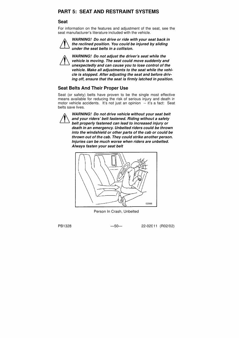
Seat (or safety) belts have proven to be the single most effectivemeans available for reducing the risk of serious injury and death inmotor vehicle accidents. It’s not just an opinion -- it’s a fact: Seatbelts save lives.
Person In Crash, Unbelted
WARNING! Do not drive or ride with your seat back in
the reclined position. You could be injured by sliding
under the seat belts in a collision.
WARNING! Do not adjust the driver’s seat while the
vehicle is moving. The seat could move suddenly and
unexpectedly and can cause you to lose control of the
vehicle. Make all adjustments to the seat while the vehi-
cle is stopped. After adjusting the seat and before driv- ing off, ensure that the seat is firmly latched in position.
WARNING! Do not drive vehicle without your seat belt and your riders’ belt fastened. Riding without a safety
belt properly fastened can lead to increased injury or
death in an emergency. Unbelted riders could be thrown
into the windshield or other parts of the cab or could be
thrown out of the cab. They could strike another person.
Injuries can be much worse when riders are unbelted.
Always fasten your seat belt
02998

7/31/2019 Peterbilt Model 387 Operators Manual
http://slidepdf.com/reader/full/peterbilt-model-387-operators-manual 53/188
PART 5: SEAT AND RESTRAINT SYSTEMS
PB1328 —51— 22-02011 (R02/02)
Shoulder Belt
Your combination shoulder-lap belt needs proper adjustment:
• The lap portion should be worn as low on the hips as possible.
Properly worn belt Improperly worn belt
• The shoulder portion should fit snugly across your body. It should
always be worn over the shoulder next to the door. It you put the
belt under your arm, it can’t protect you properly.
Correct (over arm) Incorrect (under arm)
WARNING! You can be seriously injured if your belt is
buckled too high. In a crash, it would apply force to your abdomen, not your pelvic bones. This could cause
serious internal injuries. Always wear your seat belt low
over your pelvic bones.
02928
02929

7/31/2019 Peterbilt Model 387 Operators Manual
http://slidepdf.com/reader/full/peterbilt-model-387-operators-manual 54/188
PART 5: SEAT AND RESTRAINT SYSTEMS
PB1328 —52— 22-02011 (R02/02)
• Be sure, also, that your belt is not too loose. A loose belt could
allow you to slide under it in an accident, and that could bring the
belt up around your abdomen.
• Watch that you don’t twist the belt in the process of putting it on. A
twisted belt won’t work as well to protect you.
Twisted Belt
To connect your shoulder-lap belt: Grasp the belt tongue and pullin a smooth, slow motion across your chest and lap. Insert thetongue into the buckle on the inboard side of the seat. Push downuntil you hear a click. Pull on the belt to make sure it is buckled.Check that it is positioned correctly on your body.
WARNING! Wearing the shoulder belt under your arm
could lead to serious injury. In a crash your body would
move too far forward, increasing the chance of head and
neck injury. And the belt would apply too much force to the ribs, which aren’t as strong as your shoulder bones.
You could also suffer internal injuries. Wear the shoul-
der belt over your shoulder.
WARNING! A too-loose seat belt can lead to injury in a crash. It can allow you to fall too far forward, possibly
causing head and neck injuries. You could strike the
wheel or the windshield. Adjust your belt so that there
is no more than one inch (25 mm) of slack.
WARNING! You could be seriously injured by a twisted
belt. In a crash, the full width of the belt wouldn’t be
protecting you. And the twisted belt could cut into your
body. Straighten the belt before buckling it. If you can’t,have your dealer or service person fix it.
02930

7/31/2019 Peterbilt Model 387 Operators Manual
http://slidepdf.com/reader/full/peterbilt-model-387-operators-manual 55/188
PART 5: SEAT AND RESTRAINT SYSTEMS
PB1328 —53— 22-02011 (R02/02)
Comfort Feature
Your Peterbilt contains a feature designed to eliminate cinching andprovide improved safety and comfort. Cinching is the condition where
a belt becomes continually tighter around you during a rough, bouncyride. The need for this feature increases with rough road conditions,particularly over long distances.
To eliminate cinching simply activate the comfort feature at the appro-priate time:
1. Fasten your seat belt according to the directions given earlier.
2. Lean forward to pull a little slack (about 1 inch) in the belt. Be sure
to allow only a small amount of slack. See the Warning on a loose
belt, on the previous page.3. When the slack is right, slide the comfort feature up the belt until it
engages the D-loop.
4. To release the comfort feature, reach up and pull it down along the
belt until it no longer engages the D-loop.
5. When you want to get out of the cab, release the comfort feature,
then just push the button on the buckle.
Pregnant Women: Sometimes pregnant women worry that in a crashthe seat belt could hurt the baby. But if a woman wears her belt prop-erly - low over her pelvis, below her abdomen - the belt won’t harmthe baby, even in a crash. And remember - the best way to keep anunborn baby safe is to keep the mother safe.
Pregnant Woman With Belt Properly Worn
Sleeper Bunk Restraints
If your cab is equipped with a sleeper, be sure to use the restraintdevice. You may have belts which either are over the bunk or cover

7/31/2019 Peterbilt Model 387 Operators Manual
http://slidepdf.com/reader/full/peterbilt-model-387-operators-manual 56/188
PART 5: SEAT AND RESTRAINT SYSTEMS
PB1328 —54— 22-02011 (R02/02)
the opening. Of course, you do not need to use a restraint if yousleep in a parked vehicle. But anyone using the sleeper while thetruck is in motion should be restrained in a safety device.
The bunk restraint is attached to the sleeper in six locations (see illus-tration below):
1. Two buckles at the upper rear wall
2. Two buckles at the side walls
3. Bolts in two places at the lower rear wall
There is also a buckle at the driver’s side front of the bunk ( ) foreasy entry/exit of the sleeper with the bunk restraint in use.
• The upper rear wall: Access to the bunk is easiest when these
connections are buckled and the front buckle is detached.
• The side walls: The tenting straps are attached to the side wall
sills with easy-to-use buckles.
• The lower rear wall: The restraint is attached to the lower rear wall
by bolts that do not require removal for use or stowage of the bunk
restraint.
CAUTION: To avoid damage when lifting a bunk, remove all items from the top of the bunk mattress, and arrange
bedding so that items will not slide down the mattress
and fall behind the bunk.
1
2
34
2
4

7/31/2019 Peterbilt Model 387 Operators Manual
http://slidepdf.com/reader/full/peterbilt-model-387-operators-manual 57/188
PART 5: SEAT AND RESTRAINT SYSTEMS
PB1328 —55— 22-02011 (R02/02)
You will notice that if your Peterbilt has an upper bunk, it has norestraint device. This is because no one should ever be in an upperbunk when the vehicle is moving.
PassengersAnyone riding in your vehicle should wear a seat belt. The responsi-ble operator sees to it that everyone in the vehicle rides safely - andthat means with a seat belt.
Some Other Safety Restraint Tips:
• Don’t wear belts over rigid or breakable objects in or on your cloth-
ing. Such things might be eyeglasses, pens, keys, etc. These
could cause injury in an accident.
• Damaged belts in the cab or sleeper must be replaced. Belts that
have been stretched, cut, or worn out may not protect you in an
accident.
• Avoid catching belts in the doors or seat hardware; they could be
damaged.
• Don’t modify or disassemble the seat belts in your vehicle. They
won’t be available to keep you and your passengers safe.
• Never bleach or dye seat belts; chemicals can weaken them. Do,
however, keep them clean by following the care label on the belts.
Let them dry completely before allowing them to retract.
• If any seat belt is not working properly, see an authorized Peterbilt
dealer for repair or replacement.
WARNING! •In an accident an unrestrained person lying in a sleeper
bunk could be seriously injured. He or she could be thrown from the bunk. Be sure anyone occupying the sleeper is restrained while the vehicle is moving.
•Be sure that no one ever rides in the upper bunk. That person would be thrown out in an accident and could be very seriously injured.

7/31/2019 Peterbilt Model 387 Operators Manual
http://slidepdf.com/reader/full/peterbilt-model-387-operators-manual 58/188
PART 5: SEAT AND RESTRAINT SYSTEMS
PB1328 —56— 22-02011 (R02/02)
Tether Belts
Tether belts are installed on suspension seats. They help secure theseat to the floor to restrain it in case of a sudden stop or an accident.
Tether Adjustment
• Make sure the tether belt is attached to the cab deck and seat
frame. It should be routed through the buckle on each side.
• To lengthen the tether, turn the buckle to a right angle to the web-
bing. Then pull the buckle. To shorten the tether, pull on the strap.
WARNING! Do not remove, modify, or replace the tether
belt system with a different tether system. A failed or miss-
ing tether belt could allow a seat base to fully extend in the
event of an accident leading to greater injuries or death.
WARNING! Failure to adjust tether belts properly can
cause excessive movement of the seat in an accident.
This could lead to greater injuries for you. Tether belts should be adjusted so that they are taut when the seat is
in its most upward and forward position.
WARNING! Before driving or riding in a vehicle, ensure that there is adequate head clearance at maximum upward travel of seat. Serious injury may occur if head clearance is not adequate. Shorten the tether belt as necessary to provide adequate head clearance.

7/31/2019 Peterbilt Model 387 Operators Manual
http://slidepdf.com/reader/full/peterbilt-model-387-operators-manual 59/188
PART 5: SEAT AND RESTRAINT SYSTEMS
PB1328 —57— 22-02011 (R02/02)
Inspection of the Restraint System
The typical three-point seat systems in passenger cars may seem
very similar to the three-point seat belt system in heavy duty vehicles,
but there are some key differences which all users of this system
should be aware of:
• In typical passenger vehicle automotive seat belt applications, thenormal life of the vehicles is usually 8 to 10 years and the total
mileage frequently does not exceed 125,000 miles (200,000 km).
Heavy duty vehicles often see this type of mileage in a very short
period of time, and accumulation of mileage in excess of 500,000
miles (800,000 km) during the vehicle lifetime is not unusual.
• A significant difference in the two systems is the amount of move-
ment of webbing in the system. In an automotive application, there
is little movement of the seat belt system, except when the userputs on or takes off the belt. In trucks, however, there is almost
constant movement of the belt through hardware due to ride char-
acteristics and seats which are designed to move, in order to
enhance driver comfort. There can even be movement of the web-
bing in the seat belt system when the belt is not being used. Rela-
tive movement between the seat and the cab, which normally
occurs whenever the truck is in operation, can cause wear of the
seat belt webbing.• Environmental conditions represent another major difference in
the systems in automobiles and heavy duty and specialty vehicles.
Unlike the automotive environment, heavy duty and specialty vehi-
cles may be very dirty, and have more exposure to the Sun’s dam-
aging ultraviolet rays, thus resulting in a reduction of the life of the
seat belt system.
The high mileage associated with heavy duty vehicles and possible
wear of the 3-point seat belt system, the continual relative movementof the system, the possible contact with the vehicle seat or other parts
of the cab structure, and the potential exposure of this system to
severe environmental conditions make it crucial to inspect the three-
point seat belt systems regularly. It is recommended that the seat belt
system in a vehicle be inspected every 20,000 miles (32,000 km) or
more often if the vehicle is exposed to severe environmental condi-
tions. Any seat belt system that shows cuts, fraying, extreme or
WARNING! Failure to properly inspect and maintain restraint systems can lead to serious injury or loss of
life. Without periodic inspection and maintenance to detect unsafe conditions, seat restraint components can wear out or not protect you in an accident.

7/31/2019 Peterbilt Model 387 Operators Manual
http://slidepdf.com/reader/full/peterbilt-model-387-operators-manual 60/188
PART 5: SEAT AND RESTRAINT SYSTEMS
PB1328 —58— 22-02011 (R02/02)
unusual wear, significant discoloration due to UV exposure, abrasion
to the seat belt webbing, or damage to the buckle, latch plate, retrac-
tor hardware or any other obvious problem should be replaced imme-
diately, regardless of mileage.
One of the most critical areas to be inspected is the seat belt web-
bing. Constant movement of the belt actually means the webbing is
experiencing wear as it travels in and out of the retractor, through the
pillar loop web guide and through the various pieces of hardware
associated with the belt. The following guidelines detail how to
inspect for cuts, fraying, extreme or unusual wear of the webbing, etc.
and damage to the buckle, retractor, hardware, or other factors which
indicate that belt replacement is necessary.
WARNING! It is important to remember that any time a vehicle is involved in an accident, the entire seat belt system must be replaced. Unexposed damage caused by the stress of an accident could prevent the system from functioning properly the next time it is needed,which could result in severe injury or even death.
03004

7/31/2019 Peterbilt Model 387 Operators Manual
http://slidepdf.com/reader/full/peterbilt-model-387-operators-manual 61/188
PART 5: SEAT AND RESTRAINT SYSTEMS
PB1328 —59— 22-02011 (R02/02)
1. Check the web wear in the system. The webbing must be closely
examined to determine if it is coming into contact with any sharp or
rough surfaces on the seat or other parts of the cab interior. These
areas are typical places where the web will experience cutting or
abrasion. Cuts, fraying, or excessive wear would indicate the need
for replacement of the seat belt system.
2. The D-loop web guide is the area where almost constant move-
ment of the seat belt webbing occurs because of relative move-
ment between the seat and the cab.
3. Check the comfort feature for cracks or possible damage and that
it works properly.
4. Check the buckle and latch for proper operation and to determineif the latch plate is worn, deformed, or damaged.
5. Inspect the retractor web storage device, that is mounted on the
floor or B-pillar of the vehicle for damage. The retractor is the
heart of the occupant restraint system and can often be damaged
if abused, even unintentionally. Check retractor web storage
device operation to ensure that it is not locked up and that it spools
out and retracts webbing properly.
6. If adjustable tethers are being used, be sure they are adjusted in
accordance with installation instructions. Tethers must also be
inspected for web wear, just as with the seat belt systems.
7. Mounting hardware should be evaluated for corrosion, and for
tightness of bolts and nuts.
8. Check web in areas exposed to ultraviolet rays from the sun. If the
color of the web in these areas is gray to light brown, the physical
strength of this web may have deteriorated due to exposure to the
sun’s ultraviolet rays; replace the system.
If the inspection indicates that any part of the seat belt system
requires replacement, the entire system must be replaced, both
retractor and buckle side. An installation guide is attached to every
WARNING! Failure to adjust tether belts properly can cause excessive movement of the seat in an accident.This could lead to greater injuries for you. Tether belts should be adjusted so that they are taut when the seat is in its most upward and forward position.
WARNING! Replace the entire belt system (retractor and
buckle side) if replacement of any one part is necessary.Unexposed damage to one or more components could pre- vent the system from functioning properly the next time it is needed, which could result in severe injury or even death.

7/31/2019 Peterbilt Model 387 Operators Manual
http://slidepdf.com/reader/full/peterbilt-model-387-operators-manual 62/188
PART 5: SEAT AND RESTRAINT SYSTEMS
PB1328 —60— 22-02011 (R02/02)
replacement belt. This set of instructions is entitled “THREE-POINT
SEAT BELT INSTALLATION GUIDE.” There are separate seat belt
instruction guides for suspension and fixed bench seats. Use the
proper guide for your type of seat, and follow the instructions very
closely. It is vitally important that all components must be remounted
back in the same position as the original components that were
removed. This will maintain the design integrity of the mounting points
for the seat belt assembly.
Once the need for replacement of the seat belt has been determined,
be certain that it is only replaced with the recommended replacement
seat belt. The occupant restraint system has been developed and
tested specifically for this vehicle. If the vehicle was originally
equipped with a lap belt, it cannot be replaced with a three-point
shoulder harness system, because the cab mounting points are not
structurally designed for a three-point seat belt.

7/31/2019 Peterbilt Model 387 Operators Manual
http://slidepdf.com/reader/full/peterbilt-model-387-operators-manual 63/188
PART 6: DRIVER’S CHECKLIST
PB1328 —61— 22-02011 (R02/02)
To keep your vehicle in top shape, and to maintain its high level ofsafety for you, your passengers, and your load, make a thoroughinspection every day before you drive. You’ll save maintenance timelater -- and the safety checks could help prevent a serious accident.
Please remember, too, that Federal law requires a pre-trip inspectionand so do commercial trucking companies.
For more information, you can refer to Department of TransportationRegulation 392.7 which tells you that interstate commercial motorvehicles are not to be driven unless the driver is sure that certainparts and accessories are in working order.
You aren’t expected to become a professional mechanic. The pur-pose of your inspections is to find anything that might interfere with
the safe and efficient transportation of yourself and your load. If youdo find something wrong and can’t fix it yourself, please have a quali-fied mechanic fix it right away.
Safe Vehicle Operation
For your safety, as well as those around you, be a responsible driver:
• If you drink, do not drive.
• Do not drive if you are tired, ill, or under emotional stress.
Much has gone into the manufacturing of your Peterbilt, includingadvanced engineering techniques, rigid quality control, and demand-
ing inspections. These manufacturing processes will be enhanced by
you—the safe driver—who observes the following:
• knows & understands how to operate a vehicle and all its controls
• maintains the vehicle properly
• uses driving skills wisely
The daily checks listed below are the foundation of your overall pre-ventive maintenance program. See PART 8: MAINTENANCE ANDSERVICE for the complete preventive maintenance schedule for yourvehicle.
WARNING! Do not drink and drive. Your reflexes, percep- tions, and judgment can be affected by even a small amount of alcohol. You could have a serious—or even fatal accident—if you drive after drinking. Please do not drink and drive or ride with a driver who has been drinking.The use of alcohol, drugs, and certain medications will seri- ously impair perception, reactions, and driving ability.These circumstances can substantially increase the risk of an accident and personal injury.

7/31/2019 Peterbilt Model 387 Operators Manual
http://slidepdf.com/reader/full/peterbilt-model-387-operators-manual 64/188
PART 6: DRIVER’S CHECKLIST
PB1328 —62— 22-02011 (R02/02)
Approaching the Vehicle
1. Check the overall appearance and condition. Are windows, mir-
rors, and lights clean and unobstructed?
2. Check beneath the vehicle. Are there signs of fuel, oil, or waterleaks?
3. Check for damaged, loose, or missing parts. Are there parts
showing signs of excessive wear or lack of lubrication? Have a
qualified mechanic examine any questionable items and repair
them without delay.
Checking Under the Hood or Cab
1. With the engine stopped:2. Check the engine oil level; top up as necessary. Refer to your
engine’s operating manual for the type of oil to use.
3. Check the engine coolant level while the engine is cold. Top up as
necessary with premixed coolant. Refer to the instructions on
page 164 for adding coolant to the proper level.
4. Check the engine belts. Refer to the instructions on page 165 to
check belt condition and adjust tension.
5. Check brake lines and hoses.
6. Check all other accessories, controls, belts, hoses, and wiring for
condition and adjustment.
7. Check the windshield washer fluid level; top up as necessary.
8. Check the power steering fluid reservoir; top up as necessary.
9. Check the steering components (pitman arm; draglink; power
steering hoses, etc.)
10.Drain the fuel/water separator.
Checking the Luggage Compartment
1. Check the fire extinguisher charge.
2. Check the road emergency kit. Is it complete?

7/31/2019 Peterbilt Model 387 Operators Manual
http://slidepdf.com/reader/full/peterbilt-model-387-operators-manual 65/188
PART 6: DRIVER’S CHECKLIST
PB1328 —63— 22-02011 (R02/02)
Checking Outside the Vehicle
1. Be sure all wheel studs and cap nuts are secure. Check wheel cap
nut torque weekly; refer to the instructions on page 139.
2. Check tires for condition and proper inflation.
3. Check the front wheel bearing lube level.
4. Check parking (spring) brakes as to the condition and tightness
of air lines, breathers, clamp rings & bolts, mounting studs, and
release bolts.
5. Check turn signal operation.
6. Check emergency flashers and exterior lamps.
7. Check the fuel tanks. Is there enough fuel? Are the tank caps
secure?
8. Visually inspect the fuel tank mounting hardware. Are the tank
straps tight? Is the webbing in place?
9. Check the air cleaner and muffler(s). Are they tight and secure?
10. Check the trailer connections. Are they secure and the lines
clear? If they are not being used, are they stored properly?
11. Is the trailer spare wheel secure? Inflated?
12. Is the landing gear up and the handle secured?
13. Check the 5th wheel. Is the kingpin locked?
14. Is the sliding 5th wheel locked?
15. Check for loose or missing suspension fasteners.
16. Check springs or other suspension parts for damage such as
cracks, gouges, distortions, bulges, or chafing.
17. Check the air system. Are there leaks?
18. Drain excess moisture from all air supply tanks. Make sure the
drain cocks are closed. This procedure is also required for air
supply tanks equipped with automatic drain valves.
WARNING!
•Diesel fuel in the presence of an ignition source (such as a cigarette) could cause an explosion. You could be seri- ously injured. A mixture of gasoline or alcohol with diesel fuel increases this risk of explosion. Use only the fuel recommended for your engine.
•Hot fuel vapors are combustible and can cause an explosion or fire resulting in injury or death. Do not remove a fuel tank cap near an open flame.

7/31/2019 Peterbilt Model 387 Operators Manual
http://slidepdf.com/reader/full/peterbilt-model-387-operators-manual 66/188
PART 6: DRIVER’S CHECKLIST
PB1328 —64— 22-02011 (R02/02)
In - Cab Checklist
1. Adjust the seats.
2. Fasten and adjust safety restraint belts. See PART 5: SEAT AND
RESTRAINT SYSTEMS, or the Index, under Restraint
Systems 50.3. Sleeper Restraints: Check and inspect condition. See PART 5:
SEAT AND RESTRAINT SYSTEMS, or the Index, under Restraint
Systems 50.
4. Adjust the steering column.
5. Check mirror adjustment.
6. Operate air-powered devices to circulate lubricants.
Superintendent of Documents
U.S. Government Printing Office
Washington, DC 20402
CAUTION: To avoid injury while entering or leaving the
cab, keep your feet in contact with the steps and your
hands on the handhold. Always have three points of
contact as you enter or exit a cab. See PART 2: GET-
TING INTO AND OUT OF THE CAB AND FRAME
ACCESS of this manual for more information.
NOTE: The previously-mentioned items should be checked daily, as a minimum. They are in addition to , not in place
of Federal Motor Carrier Safety Regulations. These may be
purchased by writing to:

7/31/2019 Peterbilt Model 387 Operators Manual
http://slidepdf.com/reader/full/peterbilt-model-387-operators-manual 67/188
PART 7: STARTING & OPERATING THE VEHICLE
PB1328 —65— 22-02011 (R02/02)
Since each Model 387 is custom-equipped, all engine operationinstructions in this manual are general. You will want to consult themanual for your engine to find out details about your specific engine’sneeds. You may need to use a slightly different procedure from the
one outlined here.Also check the ATA Truck Driver’s Handbook in your glove box. It willgive you tips on starting, shifting, and driving a truck.
Below are instructions for both normal-temperature starting and cold-weather starting.
Normal Starting Procedure (Normal Temperature)
When the outside temperature is above 50° F (10° C), you can use
the following procedure.1. Set the parking brake.
2. Put your main transmission in Neutral.
3. Disengage (depress) the clutch (with manual transmission).
4. Turn the key switch to ON.
• If your vehicle is equipped with a digital message center (DMC),
the DMC display will come on in the “Clock” mode.
• The multiplex instrumentation system will begin a self-test:-Gauge pointers will move to a 12:00 position, with their LED
warning lights on, for 5 seconds.
-Gauge pointers will then move to their actual gauge readings
and their LED warning lights will go off.
• The speedometer message center (SMC) will display the odome-
ter.
5. Turn the key to start.
If the engine does not start within 30 seconds, release the starter but-ton. To avoid overtaxing the starter motor or the batteries, don’t use
NOTE: If the SMC displays other messages or if other alarms
activate after the key is turned ON, see the “Warning Alarms”
section at the end of this part on page 96 .
CAUTION: Never operate the starter motor while the
engine is running. The starter and flywheel gears could
clash or jam, severely damaging them.NOTE: Some starters are equipped with overcrank protection.
Check the “Engine Operation and Maintenance Manual” for
details.

7/31/2019 Peterbilt Model 387 Operators Manual
http://slidepdf.com/reader/full/peterbilt-model-387-operators-manual 68/188
PART 7: STARTING & OPERATING THE VEHICLE
PB1328 —66— 22-02011 (R02/02)
the starter for more than 30 seconds. Let the starter motor cool andthe batteries recover for 2 minutes before trying again.
If the engine still won’t start after a couple of tries, check the manualoverride shutdown valve and fuel lines for possible fuel starvation orair leaks. Starting failure may mean fuel isn’t reaching the injectors.
6. As soon as the engine starts, begin to watch the oil pressure
gauge. Check your engine manufacturer’s manual for the right
pressure for your engine. If the oil pressure doesn’t rise within a
few seconds, stop the engine. Find out what is wrong before
restarting the engine.
7. Slowly engage (release) the clutch after the engine has started.
8. Wait until normal engine oil pressure registers on the gauge before
idling or accelerating the engine beyond 1000 RPM.
Cold Temperature Starting Procedure
In cold weather, fast engine starting helps relieve the loads on theelectrical system and cranking motor. Using the special cold startingequipment will help starting. If you follow a few simple guidelines, youwill extend the service life of your engine.
•Keep the electrical system in top condition.
•Use the best quality fuel of the recommended grade.
•Use recommended engine lubricating oil.
Engine Warmup
The purpose of engine warmup is to allow oil film to be establishedbetween pistons and liners, shafts and bearings while your enginegradually reaches operating temperature.
Warmup Procedure
1. After you’ve started your engine, idle it at approximately 600 RPM
while you check
•oil pressure
•air pressure
•alternator output
NOTE: If your vehicle has a DDC engine, and if it has not
been started for more than 30 days, squirt about half a cup
(120 ml) of clean, specified engine oil into the turbocharger
oil inlet port. Use an oil can. This will keep the turbocharger
bearings lubricated until the engine oil pressure gets up to
normal .

7/31/2019 Peterbilt Model 387 Operators Manual
http://slidepdf.com/reader/full/peterbilt-model-387-operators-manual 69/188
PART 7: STARTING & OPERATING THE VEHICLE
PB1328 —67— 22-02011 (R02/02)
2. After a few minutes of idling at 600 RPM, increase your idle speed
to 900 or 1000 RPM. Continue your warmup. This procedure
allows oil to warm and flow freely while pistons, liners, shafts, and
bearings expand slowly and evenly. In extremely cold tempera-
tures, you may have to increase idle speed.
3. Continue the engine warmup until the coolant temperature
reaches at least 130° F (54° C). At this temperature, you can use
partial throttle. Wait until the coolant temperature is at least 160° F
(71° C) before operating at full throttle.
NOTE: In colder climates where the temperature is often
below freezing, the warmup for turbocharged engines is
especially important. Chilled external oil lines leading to the
turbocharger will slow the oil flow until the oil warms, reduc-
ing oil available for the bearings. Watch the engine oil tem-
perature or pressure gauge for a warming trend before
increasing engine idle speed (RPM).
WARNING! Exhaust fumes from the engine contain carbon monoxide, a colorless and odorless gas. Do not breathe the engine exhaust gas. A poorly maintained, damaged or cor-
roded exhaust system can allow carbon monoxide to enter the cab or sleeper. Entry of carbon monoxide into the cab is also possible from other vehicles nearby. Failure to properly maintain your vehicle could cause carbon monoxide to enter the cab/sleeper and causes serious illness.
CAUTION: Never idle your vehicle for prolonged periods of time if you sense that exhaust fumes are entering the cab or sleeper. Investigate the cause of the fumes and correct it
as soon as possible. If the vehicle must be driven under these conditions, drive only with the windows slightly open. Failure to repair the source of the exhaust fumes may lead to personal harm.
NOTE: Keep the engine exhaust system and the vehicle’s cab/
sleeper ventilation system properly maintained. It is recommended
that the vehicle’s exhaust system and cab/sleeper be inspected
• By a competent technician every 15,000 miles
• Whenever a change is noticed in the sound of the exhaust system
• Whenever the exhaust system, underbody, cab or
sleeper is damaged

7/31/2019 Peterbilt Model 387 Operators Manual
http://slidepdf.com/reader/full/peterbilt-model-387-operators-manual 70/188
PART 7: STARTING & OPERATING THE VEHICLE
PB1328 —68— 22-02011 (R02/02)
Transmission Warmup
In cold weather you may find shifting sluggish when you first start theengine. Transmission warmup is especially important at this time, but
it is always a good idea to warm up your transmission before startingout on the road.
To warm up the transmission lubricating oil during engine warmup,with a single transmission:
• Check that the transmission is in Neutral.
• Release the clutch pedal.
If you have a two-transmission combination:
• Put the main transmission in gear.
• Put the auxiliary transmission in Neutral. This will allow the trans-
mission countershaft to turn, agitating the oil and warming it.
Idling the Engine
Under most circumstances, idling your engine for long periods merelywastes fuel. In severe arctic weather conditions, however, you mayneed longer idling to be sure all parts of your engine are fully lubri-
cated.
NOTE: Do not stay in the vehicle with the engine running or
idling for more than 10 minutes with the vehicle’s Heater and
A/C ventilation system in RECIRC or at LOW FAN SPEED.
Even with the ventilation system On, running the engine while parked or stopped for prolonged periods of time is not
recommended.
NOTE: If other vehicles are parked next to you idling, move
your vehicle or do not stay in your vehicle for prolonged periods
of time.
CAUTION: The use of a winterfront can result in excessive
engine coolant, oil, and charge air (intake) temperatures,which can lead to overheating and possible engine dam- age. If you must use a winterfront, refer to the “Engine Operation and Maintenance Manual” for operating restric- tions and recommendations.

7/31/2019 Peterbilt Model 387 Operators Manual
http://slidepdf.com/reader/full/peterbilt-model-387-operators-manual 71/188
PART 7: STARTING & OPERATING THE VEHICLE
PB1328 —69— 22-02011 (R02/02)
During the time it takes you to drink a cup of coffee, your engine cancool as much as 60° F (33° C) below normal operating temperature.To keep the engine warm during a short break, turn it off. And don’tallow your engine to idle longer than five minutes.
Putting The Vehicle In MotionThis section discusses the clutch and transmission operation to getyour Model 387 underway.
Shifting The Transmission
You will find a shift pattern either on a decal in your cab or on amedallion in the shift knob. Check to be sure you know the correctsequence for your particular transmission. Refer to the transmissionmanual included with your vehicle for complete instructions in theoperation of your transmission.
Shifting Gears in a New Vehicle
Shift carefully in a new vehicle. The transmission may be a little stiffat first. So be careful to avoid gear clashing.
When you are operating a new vehicle or one that has been exposedto cold weather, you want the transmission lubricant to circulate andcoat the contacting surfaces of the gears. Metal contacting metal inmoving parts may seriously damage your transmission. So don’tdrive in one gear for long until the transmission lubricant has had achance to coat those contacting surfaces.
WARNING! To reduce the chance of personal injury and/or vehicle damage from overheated engines, which can result in a fire, never leave the engine idling without an alert
driver present. If the engine should overheat, as indicated by the engine coolant temperature light, immediate action is required to correct the condition. Continued unattended operation of the engine, even for a short time, may result in serious engine damage or a fire.
CAUTION: Do not allow your engine to idle, at low rpm
(400–600 rpm), longer than five minutes. Long periods of
idling after the engine has reached operating temperatures
can decrease engine temperature and cause gummed pis- ton rings, clogged injectors, and possible engine damage
from lack of lubrication. The normal torsional vibrations
generated can also cause transmission wear.
WARNING! Do not carry loose objects in your cab, it can be
dangerous. In a sudden stop, or even going over a bump in
the road, they could fly through the air and strike you or a
passenger. You could be injured or even killed. Secure all
loose objects in the cab before moving the vehicle.

7/31/2019 Peterbilt Model 387 Operators Manual
http://slidepdf.com/reader/full/peterbilt-model-387-operators-manual 72/188
PART 7: STARTING & OPERATING THE VEHICLE
PB1328 —70— 22-02011 (R02/02)
Operating the Clutch
“Riding” the Clutch
The clutch pedal is not a footrest. Driving with your foot on the clutch
pedal will allow your clutch to slip, causing excessive heat and wear.You can damage your vehicle this way.
Clutch Travel
To put your vehicle into motion, push down on the clutch pedal untilthe clutch brake makes contact. This contact will occur at about 1/2inch to 1 inch from the end of pedal stroke. Select a gear low enoughto let your vehicle start forward with the throttle at idle until the clutchis fully engaged.
The total stroke of the clutch pedal is about 10 inches. The first 1 3/4to 2 inches is free travel. After that is the release stroke, the part thatfully releases the clutch. The last 1/2 to 1 inch engages the clutchbrake. If your vehicle is new, watch the free travel in your clutch care-fully for the first few hundred miles. As your clutch lining wears andhigh spots get worn smooth, you will get less free travel.
Always start out in a low gear with a ceramic-faced clutch. Starting inhigher gears, even with a light load, will cause a very jumpy start andexcessive wear. And don’t allow your vehicle to roll in the oppositedirection at all during clutch engagement. If you need to start up onan incline, apply your service brakes before you release the parkingbrake. Then release your service brakes as you engage the clutch
and apply throttle.Release Bearing Wear
When you must idle your engine for any period of time, shift yourtransmission to neutral and engage the clutch (take your foot off thepedal). This helps prevent unnecessary wear of your clutch releasebearing. And it is less tiring for you, too.
Clutch Adjustment
Inspect manual and self-adjusting clutches regularly to maintain cor-
rect clutch adjustment. Have your dealer’s service department per-form any adjustments necessary. Do not adjust your clutch byadjusting the external linkage without first checking (and correcting ifnecessary) the internal clutch adjustment. Using only the externallinkage adjustment could damage the clutch.
CAUTION: Always use first gear or a low speed range to
start the vehicle in motion. The use of a higher gear or
speed range forces undue strain on the engine, clutch,other transmission components, and may cause damage.

7/31/2019 Peterbilt Model 387 Operators Manual
http://slidepdf.com/reader/full/peterbilt-model-387-operators-manual 73/188
PART 7: STARTING & OPERATING THE VEHICLE
PB1328 —71— 22-02011 (R02/02)
Clutch Brake
Your clutch brake is used for stopping gear rotation to let you shift into1st gear or reverse when your vehicle is at a standstill.
About the last 1/2 to 1 inch of clutch pedal travel activates your clutchbrake. So if you are stopped and want to shift directly into 1st orreverse, depress the clutch pedal until contact with the clutch brake ismade to stop transmission gear rotation.
If you have a butt-tooth condition and can’t shift the transmission,gradually release the clutch. Then the drive gear can roll enough toallow the teeth to line up properly and complete the shift.
Double Clutching
Whether you are upshifting or down shifting, it is best to doubleclutch. Double clutching is easier on your transmission and on yourengine, helping your vehicle match engine speed with driveline speedand achieving clash-free shifts. To double clutch:
1. Push down the clutch pedal to disengage the clutch.
2. Move the gear shift lever to neutral.
3. Release the pedal to engage the clutch. This lets you control the
RPM of the mainshaft gears. Thus you can match the RPM of the
mainshaft gears to those of the output shaft.Upshifts - Let the engine and gears slowdown to the RPMrequired for the next gear. Use the tachometer to determine opti-mum RPM for gear engagement.
Downshifts - Press accelerator to increase engine and gearspeed to the RPM required in the lower gear. Use the tachometerto determine optimum RPM for gear engagement.
4. Now quickly press the pedal to disengage the clutch. Move the
gear shift lever to the next gear speed position.5. Release the pedal to engage the clutch.
CAUTION: Be careful not to apply the clutch brake while
the vehicle is moving. The purpose of the clutch brake is to stop the transmission so that you can shift into a
starting gear without grinding. Applying the clutch
brake when the vehicle is moving causes a braking
effect on the entire vehicle. This wear naturally short-
ens the service life of your clutch brake.
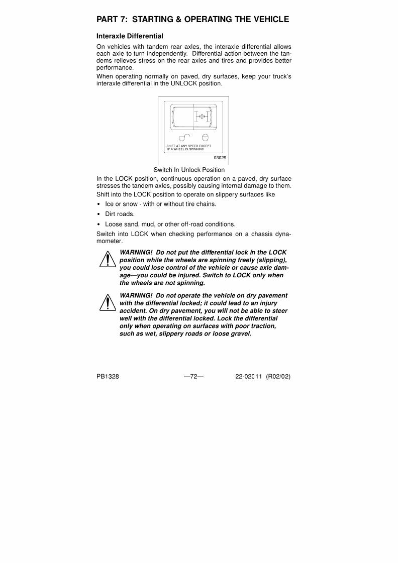
7/31/2019 Peterbilt Model 387 Operators Manual
http://slidepdf.com/reader/full/peterbilt-model-387-operators-manual 74/188
PART 7: STARTING & OPERATING THE VEHICLE
PB1328 —72— 22-02011 (R02/02)
Interaxle Differential
On vehicles with tandem rear axles, the interaxle differential allowseach axle to turn independently. Differential action between the tan-
dems relieves stress on the rear axles and tires and provides betterperformance.
When operating normally on paved, dry surfaces, keep your truck’sinteraxle differential in the UNLOCK position.
Switch In Unlock Position
In the LOCK position, continuous operation on a paved, dry surface
stresses the tandem axles, possibly causing internal damage to them.Shift into the LOCK position to operate on slippery surfaces like
• Ice or snow - with or without tire chains.
• Dirt roads.
• Loose sand, mud, or other off-road conditions.
Switch into LOCK when checking performance on a chassis dyna-mometer.
WARNING! Do not put the differential lock in the LOCK position while the wheels are spinning freely (slipping),
you could lose control of the vehicle or cause axle dam-
age—you could be injured. Switch to LOCK only when
the wheels are not spinning.
WARNING! Do not operate the vehicle on dry pavement
with the differential locked; it could lead to an injury
accident. On dry pavement, you will not be able to steer well with the differential locked. Lock the differential
only when operating on surfaces with poor traction,
such as wet, slippery roads or loose gravel.
SHIFT AT ANY SPEED EXCEPTIF A WHEEL IS SPINNING
03029

7/31/2019 Peterbilt Model 387 Operators Manual
http://slidepdf.com/reader/full/peterbilt-model-387-operators-manual 75/188
PART 7: STARTING & OPERATING THE VEHICLE
PB1328 —73— 22-02011 (R02/02)
To reduce load on the drive train, ease up on the throttle pedal when-ever you shift into LOCK or UNLOCK.
Dual Range (Two Speed) Axles
If you have this option, dual range axles provide two rear axle ratiosfor operating under heavy loads or off-highway as well as for over theroad trucking. The Low range provides maximum torque for off-roadwork. The High range is a faster ratio for highway speeds and condi-tions.
A switch on your instrument panel controls this function. You willnotice that it has a guard to protect you from activating it accidentally.
.
Range Selector
Here’s how to use your dual range axle:
1. Unlock the interaxle differential before starting.2. Put the Range Selector in the LOW range. Shift the transmission
to start the truck moving.
3. Off-Highway: When you are driving on rough terrain and second-
ary roads, or under a very heavy load, keep the axle in the LOW
range. Shift your transmission to maintain the road speed you
want.
WARNING! Do not use the differential lock during
downhill operation or at speeds above 25 mph (40 km/
h). When it is engaged under these conditions, your
vehicle will exhibit “understeer” handling characteris- tics. This “understeer” condition will cause your vehicle
to not turn as quickly and more steering effort will be
required, which can cause an injury accident.
WARNING! Never shift the axle when moving down hill.Engine driveline disengagement may occur, eliminating engine retardation and allowing the wheels to spin faster than the current speed of the engine. This may require severe braking to slow the vehicle down and can result in an injury accident.
03030
2

7/31/2019 Peterbilt Model 387 Operators Manual
http://slidepdf.com/reader/full/peterbilt-model-387-operators-manual 76/188
PART 7: STARTING & OPERATING THE VEHICLE
PB1328 —74— 22-02011 (R02/02)
4. When you go from off-highway to highway driving, shift the axle to
the HIGH range this way:
• Be sure the differential is UNLOCKED.
• Keep the accelerator down and move the Range Selector lever toHIGH.
• Keep driving with the accelerator down until you want the axle to
shift.
• Then release the accelerator until the axle has shifted.
• You are now in the HIGH axle range on the highway. Shift the
transmission normally to reach your desired cruising speed.
5. If you need to downshift the axle for more power:
• Keep the accelerator down and move the Range Selector lever to
LOW.
• Keep driving with the accelerator down until you want to downshift
the axle.
• Then release and depress the accelerator pedal quickly to
increase the engine RPM.
• The axle will shift to the LOW range.
Important Tips on Operating Your Dual Range Axle
•
To avoid damaging your vehicle, shift the axle at a slower speeduntil you are used to driving with the dual range axle.
When you are driving on a surface with good traction, keep the inter-axle differential unlocked. You can drive with the axle in the LOW orHIGH range.
Interaxle In Unlock
NOTE: If your vehicle has an automatic transmission, it may
be necessary to shift it to the Neutral position momentarily to
allow the main differential lock splines to fully engage or dis-
engage.
SHIFT AT ANY SPEED EXCEPTIF A WHEEL IS SPINNING
03029

7/31/2019 Peterbilt Model 387 Operators Manual
http://slidepdf.com/reader/full/peterbilt-model-387-operators-manual 77/188
PART 7: STARTING & OPERATING THE VEHICLE
PB1328 —75— 22-02011 (R02/02)
• When you are driving with poor traction, lock the differential. When
you have the differential locked, drive with the axle in LOW range
only.
Interaxle In Lock
• Always UNLOCK the interaxle differential before shifting the axlespeed range.
• Park the truck with the Range Selector in LOW.
Automated Transmission
An automated transmission makes shifting much easier, of course.But because your truck pulls a heavy load, if you have such a trans-mission, it is important to use it efficiently. For correct operation, seethe manual for your automated transmission included with your vehi-cle.
CAUTION: If you shift the axle range with the interaxle
differential in LOCK, you could do serious damage to
your axles. Never shift the axle range with the differen-
tial locked.
WARNING! If your vehicle has a Freedomline™ trans- mission, be aware that it can roll backwards when
stopped on a hill or grade, or when starting from a stop
on a hill or grade. This could cause serious damage or
personal injury. Observe the following guidelines:
•When stopped on a hill or grade, press the brake pedal.
•When starting from a stop on a hill or grade, quickly
remove your foot from the brake pedal and firmly press
on the accelerator pedal.
SHIFT AT ANY SPEED EXCEPTIF A WHEEL IS SPINNING
03029A

7/31/2019 Peterbilt Model 387 Operators Manual
http://slidepdf.com/reader/full/peterbilt-model-387-operators-manual 78/188
PART 7: STARTING & OPERATING THE VEHICLE
PB1328 —76— 22-02011 (R02/02)
Auxiliary Transmission
If you have an auxiliary transmission, see your transmission manufac-turer’s manual for its proper operation.
If Your Vehicle Must Be Towed
Returning a Towed Vehicle to Service
You will have to add lubricant to prevent damage after your vehiclehas been towed.
1. Into the pinion cage, add 1 pint (.47 liter) of lubricant.
or
Into the inter-axle differential, add 2 pints (.94 liter) of lubricant.
See the Index, under Lubricant Specifications, for the lubricantrequired by each axle.
2. After adding the specified type and amount of lubricant, drive the
vehicle. It should be unloaded. Drive 1 to 2 miles (1.5 to 3 km) at
a speed lower than 25 mph (40 km/h).
This will thoroughly circulate the lubricant through the assembly.
Anti-Lock Braking System Operating Information
A Model 387 is equipped with an anti-lock braking system (ABS). ThisABS reduces the possibility of wheel lock-up. If a wheel is about tolock during braking, the ABS will automatically adjust air pressure tothe brake chambers on the appropriate wheel(s) to prevent wheellock-up. The ABS is automatically turned on when the ignition switchis turned on.
CAUTION: Remove the driveline and axle shafts or lift
the driving wheels off the ground before towing the
vehicle. You could seriously damage your vehicle by
towing it with the driveline connected and the drive
wheels on the ground. Worse, when vehicles are towed
either by wrecker or piggy-back, the lubricant in the top
front of the drive axle will drain to the rear. This will leave the top components dry. The resulting friction will
seriously damage them. Always remove the main drive-
shaft and axle shafts before towing your vehicle.
WARNING! The brake system is a critical vehicle safety
system. For the safety of you and others around you,
have the vehicle submitted for periodic preventive main-
tenance checks as well as having any suspected prob-
lems immediately checked by an Authorized Service
Center. Failure to properly maintain your brake system
can lead to serious injury accidents.

7/31/2019 Peterbilt Model 387 Operators Manual
http://slidepdf.com/reader/full/peterbilt-model-387-operators-manual 79/188
PART 7: STARTING & OPERATING THE VEHICLE
PB1328 —77— 22-02011 (R02/02)
ABS Warning Lamps
Truck/Tractor ABS Warning Lamp
A truck/tractor ABS warning lamp illuminates when the ignition switchis first turned on and will remain on until the system self-test has been
completed successfully. Normally, this ABS lamp will remain on until aspeed of no more than 9 mph has been reached and the speed sen-sors have been checked for correct output. The lamp should remainoff after this point unless a problem in the system is detected.
The truck/tractor ABS lamp is located in the warning lamp cluster.(See illustration on page 42.).
WARNING! Do not drive through water deep enough to
wet brake components, as it may cause the brakes to
work less efficiently than normal. The vehicle’s stopping
distance may be longer than expected, and the vehicle may pull to the left or right when brakes are applied,
which could contribute to an accident.
WARNING! Do not rely on an anti-lock brake system that is
functioning improperly. You could lose control of the vehi-
cle resulting in a severe accident and personal injury. If an
ABS lamp goes on while you are driving or stays on after
the self-check, that anti-lock system might not be working.
The ABS may not function in an emergency. You will still have conventional brakes, but not anti-lock brakes. If any
warning lamp indicates a problem, have that ABS checked.
CAUTION: If the truck/tractor ABS warning lamp does
not illuminate when the ignition is first turned on, there
is a problem with the bulb or wiring. The driver should
have this checked as soon as possible.
02999A
ABS

7/31/2019 Peterbilt Model 387 Operators Manual
http://slidepdf.com/reader/full/peterbilt-model-387-operators-manual 80/188
PART 7: STARTING & OPERATING THE VEHICLE
PB1328 —78— 22-02011 (R02/02)
Trailer ABS Warning Lamp
Trucks, tractors, and trailers built on and after March 1, 2001 areequipped with power line communication (PLC) per U.S. FMVSS 121,
including a PLC Trailer ABS warning lamp in the cab (see page 42):
A trailer ABS warning lamp will illuminate for a bulb check when theignition switch is first turned on - whether or not a trailer is connectedto the vehicle. If the bulb check is satisfactory, the lamp will next doeither of the following:
1. If no trailer is connected, or if a non-ABS-equipped trailer is con-
nected, the trailer ABS lamp will go off after a few seconds.
2. If an ABS-equipped trailer is properly connected, the trailer ABS
warning lamp will remain illuminated for a few more seconds while
the trailer ABS is tested.
• If no trailer ABS problems are detected, the lamp will go off.
• If a trailer ABS problem is detected, the lamp will remain on. Thedriver should have the trailer’s ABS problem corrected before thevehicle is driven with that trailer attached.
CAUTION: If the trailer ABS warning lamp does not illu-
minate when the ignition is first turned on, there is a
problem with the bulb or wiring. The driver should have
this checked as soon as possible.
NOTE: A successsful warning lamp illumination and bulb
check at ignition on does not indicate that the trailer you may
be connected to has trailer ABS. You should personally inspect every trailer to determine its braking system.
NOTES:
• A “properly connected” ABS-equipped trailer is -a trailer with PLC hooked up to the J560 connector -a trailer without PLC that is hooked up to an optional ISO 3731 connector
• For doubles or triples: PLC does not distinguish between trailers. An ABS problem in any trailer will activate the trailer ABS warning lamp.
ABS

7/31/2019 Peterbilt Model 387 Operators Manual
http://slidepdf.com/reader/full/peterbilt-model-387-operators-manual 81/188
PART 7: STARTING & OPERATING THE VEHICLE
PB1328 —79— 22-02011 (R02/02)
Wheel Spin Control Warning Lamp
Your truck/tractor ABS may have an acceleration slip regulation (ASR)or automatic traction control (ATC) feature. This feature is controlled
by a switch as shown in the next illustration. Either of these features ismonitored by a warning lamp located on the main dash..
The Wheel Spin Control warning lamp will briefly illuminate and thengo out when the ignition switch is first turned on. The Wheel SpinControl warning lamp will illuminate whenever the ASR or ATC sys-tem detects drive wheel spin. The lamp will remain illuminated as longas wheel spin is detected and the ASR or ATC system is applying the
drive wheel brakes or reducing engine torque. Do not allow the WheelSpin Control lamp to remain on continuously for an extended length oftime. Extended continuous use of the ASR / ATC can cause overheat-ing of the drive wheel brakes. Engine torque or vehicle speed shouldbe reduced to eliminate wheel spin and prevent excessive applicationof the ASR / ATC system. Except for checking for proper illuminationof the ABS and Wheel Spin Control warning lamps when first startingthe truck, and for monitoring these lamps while driving, no specialoperating procedures are required. For a detailed system description,
see service literature for your specific ABS that was provided withyour vehicle.
Brake Safety and Emergency
WARNING! Do not operate the vehicle in the event of a
malfunction in any air circuit. The vehicle should not be
operated until the system is repaired and both braking
circuits, including all pneumatic and mechanical com-
ponents, are working properly. Loss of system air can
cause the service brakes not to function resulting in the
sudden application of the spring brakes causing wheel
lock-up, loss of control, or overtake by following vehi-
cles. You could be in an accident and severely injured.
I
0
ATC
03034

7/31/2019 Peterbilt Model 387 Operators Manual
http://slidepdf.com/reader/full/peterbilt-model-387-operators-manual 82/188
PART 7: STARTING & OPERATING THE VEHICLE
PB1328 —80— 22-02011 (R02/02)
To stop your vehicle in an emergency, vary the service brake applica-tion pressure to provide maximum braking force without locking thewheels. Use engine compression to assist the service brakes; i.e.,don’t depress the clutch pedal until the engine reaches idle speed.
Overheated Brakes
Under normal braking conditions, the energy generated will bring theinternal brake drum temperature to about 500° F (260° C). This iswell within the safe zone: The maximum safe temperature of liningsfor drum type brakes is usually about 800° F (427° C).
But if service brakes are used improperly or for prolonged periods,internal brake drum temperatures may commonly exceed 800° F(427° C). Such brake overheating may be detected by a burningsmell or smoke coming from a drum. If this occurs, you should imme-diately stop and check for cracked brake drums or lining fires. If nei-ther exists, get back behind the wheel and resume a slow speed assoon as possible to cool the brakes.
Parking Brakes and Their Use
The yellow diamond-shaped knob on your instrument panel controlsyour parking brakes. These are spring brakes which you activate byreleasing air pressure from their chambers. When they are not in use,air pressure compresses the springs and releases the brakes. Butputting the valve in the “Park” position exhausts air from the chambers
and allows the springs to extend and apply the brakes. Also, if yoursystem air drops below the safe operating level, the spring brakes willapply automatically, bringing your vehicle to a stop.
WARNING! Unless you have an anti-lock braking sys- tem, always avoid completely depressing the service brake pedal, if possible, even during emergency brak-
ing. Depressing the brake pedal too aggressively can cause the wheels to lock, which can lead to an uncon- trolled skid and could cause an accident.
WARNING! On trailers built before March 1975 you may
not have parking brakes if the trailer reservoir pressure
leaks down. If you depend on them to hold your vehicle,
they could release, causing a serious accident. These
older trailers have emergency brakes not designed for
parking. They will apply only if there is enough trailer
reservoir pressure. Don’t use your trailer emergency
brakes for parking. Apply your tractor parking valve
too.

7/31/2019 Peterbilt Model 387 Operators Manual
http://slidepdf.com/reader/full/peterbilt-model-387-operators-manual 83/188
PART 7: STARTING & OPERATING THE VEHICLE
PB1328 —81— 22-02011 (R02/02)
Red / Yellow Controls
To apply all your parking brakes, pull the yellow knob Out. The park-ing brakes will set. And the trailer air supply valve (red octagon knob)will automatically pop out, releasing air pressure and setting the trailerbrakes.
WARNING! Do not leave the cab without applying the
parking brake. The truck could roll and cause an injury
accident. Always apply the parking brake before you
leave the cab.
WARNING! Stopping with the parking brake controls
can cause a sudden wheel lock-up, loss of control, or
can cause you to be overtaken by following vehicles.
You could be severely injured. Never pull out the park-
ing brake valve while the vehicle is moving.
WARNING! Do not use the trailer hand brake or service
brakes to park and hold an unattended vehicle—use the
parking brakes. Because service brakes work with air
pressure, these brakes could slowly release. Your vehi-
cle could roll, causing a serious accident. Someone
could be hurt or killed. Never rely on the service brakes
to hold a parked vehicle.
WARNING! Never drive your vehicle with the parking brake
applied. Always release the parking brakes prior to moving
the vehicle. Failure to disengage the parking brakes prior
to moving your vehicle could result in excessive heat build-
up in the brake system, resulting in a fire.
NOTE: Today’s diesel electronic engines have significant
torque and startability power at low RPM. Combinations of
engine speed and available torque may over-power the vehi- cle’s parking brakes.
0290

7/31/2019 Peterbilt Model 387 Operators Manual
http://slidepdf.com/reader/full/peterbilt-model-387-operators-manual 84/188
PART 7: STARTING & OPERATING THE VEHICLE
PB1328 —82— 22-02011 (R02/02)
To release your vehicle’s brakes ONLY, push in the yellow knob. Yourtrailer will remain parked.
• To release the trailer brakes ONLY, push in the red knob. The vehiclewill remain parked.
• To release the full combination of brakes, push in BOTH yellow and
red knobs.
Trailer Air Supply Valve
The red octagon knob controls the air supply to the trailer.
To supply air to the trailer system and release the trailer parking brakes:
• Allow the tractor air system pressure to build up to operating level.
• Push the red knob in.
• Hold the red knob in by hand until the trailer air pressure builds to
a pre-set level, about 45 psi. At this point it will remain in.
The yellow knob will remain out; the tractor will remain parked. If youever have a failure or disconnect of the air supply hose to the trailer,the trailer parking brakes will set. The red knob will automatically popout and seal off the tractor air reservoirs to protect the tractor air sys-tem pressure. When operating the tractor “bobtail,” the red knob mustremain out to protect the tractor air system pressure
CAUTION: Do not try to put the vehicle in motion before
pressure in the system reaches 100 psi (689 kPa)
because the wheels are locked by the spring brake
action. Unnecessary stress and possible brake malfunc- tion could occur if the vehicle is forced to move before
the air system reaches 100 psi (689 kPa).

7/31/2019 Peterbilt Model 387 Operators Manual
http://slidepdf.com/reader/full/peterbilt-model-387-operators-manual 85/188
PART 7: STARTING & OPERATING THE VEHICLE
PB1328 —83— 22-02011 (R02/02)
Manually Releasing Spring Brakes
You may sometime have to release your vehicle’s spring brakes byhand to allow the vehicle to be towed. This could happen if the sys-
tem air pressure doesn’t reach operating pressure because yourengine or compressor is not working properly. You will have torelease the spring brakes at the spring brake chambers.
WARNING! Do not operate a vehicle when the spring
brakes have been released manually. Driving a vehicle
that has had its spring brakes manually released is
extremely dangerous. You would probably have no
brakes at all. You could have a serious or fatal accident.
WARNING! Releasing the spring brakes on an unse-
cured vehicle could lead to an accident. The truck could
roll, causing severe injury. Always secure the truck with
wheel chocks, chains, or other safe means to prevent
rolling before manually releasing the spring brakes.
WARNING! Disassembling the spring brake chamber is
dangerous and could cause serious injury. These
chambers contain a powerful spring that is compressed.Sudden release of this spring could cause you to be
badly injured. Do not disassemble a spring brake cham-
ber.
NOTE: The primary purpose of the manual release feature
is to permit the vehicle to be towed to a repair facility.

7/31/2019 Peterbilt Model 387 Operators Manual
http://slidepdf.com/reader/full/peterbilt-model-387-operators-manual 86/188
PART 7: STARTING & OPERATING THE VEHICLE
PB1328 —84— 22-02011 (R02/02)
To release spring brakes manually:
1. Remove the cap from
the spring chamber.
2. Remove the release
stud assembly from
the side pocket;
remove the release
nut and washer from
the release stud.
3. Slide out the release
stud.
02936

7/31/2019 Peterbilt Model 387 Operators Manual
http://slidepdf.com/reader/full/peterbilt-model-387-operators-manual 87/188
PART 7: STARTING & OPERATING THE VEHICLE
PB1328 —85— 22-02011 (R02/02)
4. Insert the release stud
through the opening in
the spring chamber
where the cap was
removed. Insert it into
the pressure plate.
Turn the release stud
1/4-turn clockwise in
the pressure plate; this
secures the cross pin
into the cross pin area
of the pressure plate &
locks it into the manualrelease position.
5. Assemble the release
stud washer and nut
on the release stud.
6. WIth a wrench, turn the
release stud assemblynut until the compression
spring is 90% - 95%
caged. While doing this,
ensure the push rod
(adapter push rod or ser-
vice push rod) is retract-
ing. Do not overtorque
the release stud assem-bly. (S-Cam type maxi-
mum 50 lb.-ft., Wedge
type maximum 30 lb.-ft.)
The spring brake is now
mechanically released.
02937

7/31/2019 Peterbilt Model 387 Operators Manual
http://slidepdf.com/reader/full/peterbilt-model-387-operators-manual 88/188
PART 7: STARTING & OPERATING THE VEHICLE
PB1328 —86— 22-02011 (R02/02)
Retarders
Various retarders are available which function against the engine,driveline, or transmission. These are devices that use your engine’s
power to slow down your vehicle. They save wear and tear on yourservice brakes and can be a safety feature, too, because they cankeep your brakes from overheating.
Ideally, you should always slow your vehicle with your retarder (wherepermitted by law) and use your service brakes only for stopping com-pletely. Operating this way will greatly prolong the life of your brakes.
Driving Bobtail or with an Unloaded Trailer
Do not use your engine retarder to slow down when you are bobtailingor pulling an empty trailer.
WARNING! In an emergency, the retarder might not stop
you fast enough to prevent an accident. You could be
badly hurt if you relied only on your retarder. Use the service brakes for quick stops. The retarder is not an
emergency brake.
WARNING! The retarder is NOT intended as the primary
brake for the vehicle, nor is it an emergency brake. The
retarder only helps the service brakes by using pressure
to slow the drivetrain. Use the service brakes for quick
stops.WARNING! The service brakes must be used in an
emergency. The retarder alone might not stop you fast
enough to prevent an accident. You could be badly hurt
if you relied only on the retarder.
WARNING! Do not use the retarder when operating on
road surfaces with poor traction (such as wet, icy, or
snow covered roads or gravel). Retarders can cause the wheels to skid on a slippery surface. You could lose
control of the vehicle if the wheels begin to skid, result-
ing in an accident.
WARNING! Using an engine retarder can cause a wheel lockup. The trailer is not loading the tires enough to
give the traction you may need. When you are bobtail or
unloaded, you can have a serious accident if your
wheels lock suddenly during braking. You could be
injured. Don’t use your retarder when you are driving
bobtail or with an unloaded trailer.

7/31/2019 Peterbilt Model 387 Operators Manual
http://slidepdf.com/reader/full/peterbilt-model-387-operators-manual 89/188
PART 7: STARTING & OPERATING THE VEHICLE
PB1328 —87— 22-02011 (R02/02)
Pyrometer
Maintaining Correct Operating Temperature
The optional pyrometer indicates engine exhaust gas temperature.
Because it responds almost immediately to changes in exhaust tem-perature, the pyrometer is an excellent indicator of engine output.
If you watch engine speed and exhaust temperature ranges, thepyrometer can help you operate your truck more efficiently and avoidsudden changes in engine operating temperature.
Procedure For Reducing High Pyrometer Temperature Readings
1. If the pyrometer indicates excessive temperature, ease up slightlyon the throttle.
2. If RPM and speed drop, downshift one gear to help lower the
exhaust temperature.
3. Observe the pyrometer reading. If the temperature continues to be
high, continue downshifting until acceptable operating tempera-
tures can be maintained.
Stopping The EngineBefore Stopping The Engine
A hot engine stores a great amount of heat, and it doesn’t cool downimmediately after you shut it off. Always cool your engine downbefore shutting it off. You will greatly increase its service life.
Idle the engine at 1000 RPM for five minutes. Then low idle for thirtyseconds before shutdown. This will allow circulating coolant andlubricating oil to carry away heat from the cylinder head, valves, pis-
tons, cylinder liners, turbocharger, and bearings. This way you canprevent serious engine damage that may result from uneven cooling.
Turbochargers
This cooling-down practice is especially important on a turbochargedengine. The turbocharger contains bearings and seals that are sub- jected to hot exhaust gases. While the engine is operating, heat is
CAUTION: Do not allow the pyrometer reading to
exceed the specified maximum operating temperature.
If the pyrometer has no label specifying the maximum
operating temperature for the pyrometer, contact your engine distributor for a recommendation.
NOTE: Different size injectors or changes in altitude may
affect engine operating and exhaust temperatures.

7/31/2019 Peterbilt Model 387 Operators Manual
http://slidepdf.com/reader/full/peterbilt-model-387-operators-manual 90/188
PART 7: STARTING & OPERATING THE VEHICLE
PB1328 —88— 22-02011 (R02/02)
carried away by circulating oil. If you stop the engine suddenly after ahard run, the temperature of the turbocharger could rise as much as100°F (55°C) above the temperature reached during operation. Asudden rise in temperature like this could cause the bearings to seize
or the oil seals to loosen.
Refuel Before the Final Stop
Air space in your fuel tanks allows water to condense there. To pre-vent this condensation while you are stopped, fill your tanks to 95% ofcapacity.
Final Stop
To make sure your vehicle is ready to go after a long stop (such asover night), please follow the suggestions below. Your vehicle will beeasier to get going when you are ready, and it will be safer for anyonewho might be around it.
Please remember, too, that in some states it is illegal to leave theengine running and the vehicle unattended.
Final Stopping Procedures
1. Set the parking brake before leaving the driver’s seat.
To hold your vehicle while it is parked, don’t rely on
•Air Brakes
•Hand Control Valve for Trailer Brakes
•Engine Compression
WARNING! Using the trailer hand brake or air brakes to
hold a parked vehicle is dangerous. Because they work
with air pressure, these brakes could come loose. Your
vehicle could roll, causing a serious accident. Someone
could be hurt or killed. Always set the parking brakes.
Never rely on the trailer hand brake or truck air brakes
to hold a parked vehicle.

7/31/2019 Peterbilt Model 387 Operators Manual
http://slidepdf.com/reader/full/peterbilt-model-387-operators-manual 91/188
PART 7: STARTING & OPERATING THE VEHICLE
PB1328 —89— 22-02011 (R02/02)
2. If you are parked on a steep grade, block the wheels.
Blocked Wheels
3. Drain water from the air reservoirs.
While the engine and air supply system are still warm, drain mois-ture from the air reservoirs. Open the reservoir drains just enoughto drain the moisture. Don’t deplete the entire air supply. Be sureto close the drains before leaving the vehicle.
Opening Drains
4. Secure the vehicle. Close all the windows and lock all the doors.
02938
02939

7/31/2019 Peterbilt Model 387 Operators Manual
http://slidepdf.com/reader/full/peterbilt-model-387-operators-manual 92/188
PART 7: STARTING & OPERATING THE VEHICLE
PB1328 —90— 22-02011 (R02/02)
Setting Ride HeightVehicles equipped with rear air suspensions have their ride heightand axle (pinion) angle(s) preset at the factory. These are precisionsettings and should not be altered. Incorrectly adjusted ride height
may result in improper interaxle U-joint working angles. This canresult in premature driveline wear and driveline vibration. If your vehi-cle is equipped with a Peterbilt rear air suspension, and if it becomesnecessary to reset the ride height, you may temporarily set it by fol-lowing the next procedure. Proper ride height measurement and val-ues are shown in the illustration and table below.
Ride Height Measurement (Location for Tandem Axles Shown)
Follow this procedure to temporarily set ride height.
1. Ensure that the air supply and delivery plumbing of the height con-trol valve is consistent with the illustration on the next page.
Proprietary Rear Air SuspensionRide Height [inches (mm)]*
Single Drive Tandem Drive
Air Leaf N/A 11.70 (297)
Air Trac 11.00 (279) 11.00 (279)
Low Air Leaf 8.50 (216) 8.50 (216)
Low Low Air Leaf N/A 6.50 (165)
FLEX Air N/A 8.50 (216)
*These values are for a fully laden vehicle
WARNING! To prevent possible injury and damage to property, ensure that a vehicle is parked and the wheels chocked before beginning this procedure.
CAUTION: Completing this procedure will enable you to safely reach the nearest authorized Peterbilt repair facil-
ity to have ride height and pinion angle reset using the proper equipment and technique. Do this as soon as possible to avoid potential driveline damage.
NOTE: Suitable wheel chocks are at a minimum an 18-inch (46 cm) long 4x4.
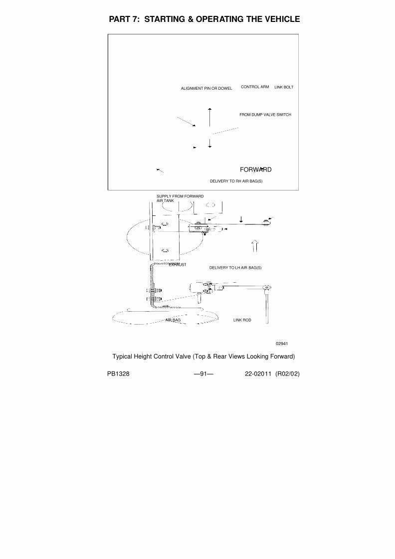
7/31/2019 Peterbilt Model 387 Operators Manual
http://slidepdf.com/reader/full/peterbilt-model-387-operators-manual 93/188
PART 7: STARTING & OPERATING THE VEHICLE
PB1328 —91— 22-02011 (R02/02)
Typical Height Control Valve (Top & Rear Views Looking Forward)
FORWARD
ALIGNMENT PIN OR DOWEL LINK BOLT
FROM DUMP VALVE SWITCH
CONTROL ARM
MOUNTING NUTS
SUPPLY FROM FORWARDAIR TANK
DELIVERY TO RH AIR BAG(S)
DELIVERY TO LH AIR BAG(S)
AIR BAG LINK ROD
EXHAUST
02941

7/31/2019 Peterbilt Model 387 Operators Manual
http://slidepdf.com/reader/full/peterbilt-model-387-operators-manual 94/188
PART 7: STARTING & OPERATING THE VEHICLE
PB1328 —92— 22-02011 (R02/02)
2. Loosen the fasteners mounting a height control valve to its bracket.
3. Rotate the valve either clockwise or counterclockwise until air pres-sure in the air springs provides the ride height specified for thatsuspension. Measure the ride height from the bottom of the framerail to the approximate centerline of the rearmost drive axle hub:
• For tandem axles, make the vertical measurement at the center-
line of the suspension (see illustration on page 91).
• For a single axle, make the measurement in front of the axle, in the
area forward of the tires but not past the suspension bracket.
4. When at the correct ride height, ensure that the height control
valve lever is in the neutral position, then install either the built-inalignment pin or a 1/8-inch (3 mm) dowel (see page 91).
5. Torque the mounting fasteners to 55 — 75 Lb. in. (6.2 — 8.5 N.m.).
6. Remove the alignment pin or dowel.
7. Repeat Steps 2 through 6 above for the RH valve on vehicles witha dual-valve system.
CAUTION:
•The rear of a vehicle will drop about 3 1/2 inches (88 mm) when the air springs are deflated. Ensure that no
persons or objects that could be injured or damaged are under the vehicle before deflating the air springs.
•To minimize risk of damage or injury, do not use a dump valve to deflate the air springs. Rotate the height control valve(s) manually to ensure positive control of air spring deflation.
•To minimize risk of injury, keep away from air springs as they are being inflated.
NOTE: On dual-valve systems, begin with the LH valve on the next step.
NOTE: At least one of the mounting holes in the height con-
trol valve bracket will be slotted to permit rotating the valve.

7/31/2019 Peterbilt Model 387 Operators Manual
http://slidepdf.com/reader/full/peterbilt-model-387-operators-manual 95/188
PART 7: STARTING & OPERATING THE VEHICLE
PB1328 —93— 22-02011 (R02/02)
Driving With Deflated Air Springs
If an air spring is ruptured, there will be enough air pressure to drivethe vehicle to a safe stop off the highway to investigate the problem.
You can get to a repair facility if you do the following:
• Remove the height control link connected to the axle and to thesuspension air valve control arm. This will cause the air valve con-trol arm to center in the closed position.
• The air system can then be pumped up to normal pressure forcontinued operation.
WARNING! Your brakes could fail if you continue driv- ing with deflated air springs. Air escaping from the sys-
tem will lower the air pressure, which could cause a
spring brake to engage. The spring brake may cause
your brakes to drag and burn up the linings. Don’t con-
tinue to operate in this condition.
WARNING! Low air pressure could make the brakes
unsafe for driving. Before driving the vehicle, make
sure the pressure does pump up to over 100 psi for nor-
mal brake operation. If the air pressure does not pump up to at least 100 psi, don’t try to move the vehicle.
CAUTION: Operating a vehicle with air suspension bags
either overinflated or underinflated may cause damage
to driveline components. If a vehicle must be operated
under such conditions, do not exceed 5 mph.

7/31/2019 Peterbilt Model 387 Operators Manual
http://slidepdf.com/reader/full/peterbilt-model-387-operators-manual 96/188
PART 7: STARTING & OPERATING THE VEHICLE
PB1328 —94— 22-02011 (R02/02)
Driving Tips And TechniquesThis section covers additional driving tips and techniques on how todrive your Peterbilt more efficiently. For further information, read theAmerican Trucking Association’s (ATA) Truck Driver’s Handbook . Itwill give you more tips on starting, shifting, and driving your vehicle.
Coasting
Do not coast with the transmission in neutral or with the clutch pedaldepressed. Besides being illegal and dangerous, coasting is alsoexpensive. It causes premature failure or damage to the clutch and
transmission and overloads the brake system.Coasting with the transmission in neutral also prevents proper transmis-sion component lubrication. During coasting the transmission is driven bythe rear wheels, and the countershaft gear (which lubricates the transmis-sion components by oil splash) will only be turning at idle speed.
Descending a Grade
WARNING! Do not coast with the transmission in neu- tral or with the clutch pedal depressed—it is a danger- ous practice. Without the use of the retarding power of the drivetrain, your vehicle can reach dangerous speeds. At very high speeds you may not be able to put the transmission in any gear. At high speeds you could seriously damage your vehicle or cause an accident when you put the transmission in gear. The engine speed could exceed the maximum governed speed and cause a serious accident due to mechanical failures.
WARNING! Do not hold the brake pedal down too long or
too often while going down a steep or long grade. This
could cause the brakes to overheat and reduce their effec-
tiveness. As a result, the vehicle will not slow down at the
usual rate. To reduce the risk of personal injury and/or an
accident, before going down a steep or long grade, reduce
speed and shift the transmission into a lower gear to help control your vehicle speed. Failure to follow procedures for
proper downhill operation could result in loss of vehicle
control.

7/31/2019 Peterbilt Model 387 Operators Manual
http://slidepdf.com/reader/full/peterbilt-model-387-operators-manual 97/188
PART 7: STARTING & OPERATING THE VEHICLE
PB1328 —95— 22-02011 (R02/02)
Engine Overspeed
• Operate the engine within the optimum engine rpm range and donot allow the rpm’s to exceed the maximum governed speed. See
your Engine Operation and Maintenance manual for informationregarding engine rpm. When the engine is used as a brake to con-trol vehicle speed (e.g., while driving down a grade), do not allowthe engine rpm to exceed maximum governed speed.
• Under normal load and road conditions operate the engine in thelower end of the range.
Use of Tachometer
The tachometer is an instrument that aids in obtaining the best perfor-
mance of the engine and manual transmission, serving as a guide forshifting gears. Refer to the Engine Operation and Maintenance man- ual for optimum engine rpm.
If the engine rpm moves beyond the maximum governed speed, indi-cating an overspeed condition, apply the service brake or shift to ahigher gear to bring engine rpm within the optimum speed range.
• When driving downhill: shift to a lower gear, use the engine brake(if so equipped), and use the service brake, keeping the engine
speed below 2,100 rpm.When the engine speed reaches its maximum governed speed, theinjection pump governor cuts off fuel to the engine. However, the gov-ernor has no control over the engine rpm when it is being driven bythe vehicle’s transmission, for example, on steep downgrades. Applyservice brakes or shift to a higher gear.
Fuel economy and engine performance is also directly related to driv-ing habits:
• The best results in trip time and fuel economy are obtained whiledriving the vehicle at a steady speed.
• Shift into higher or lower gears (or apply the service brake) to keepengine rpm near the lower end of the optimum operating range.
• Avoid rapid acceleration and braking.
CAUTION: To avoid engine damage, do not let the engine
rpm go beyond the maximum governed rpm—valve dam-
age could result if overspeed conditions occur.
NOTE: Often these recommendations are secondary to main-
taining an adequate and safe speed relative to the surrounding
traffic and road conditions.

7/31/2019 Peterbilt Model 387 Operators Manual
http://slidepdf.com/reader/full/peterbilt-model-387-operators-manual 98/188
PART 7: STARTING & OPERATING THE VEHICLE
PB1328 —96— 22-02011 (R02/02)
Warning Alarms
A warning alarm occurs when some condition in the vehicle requiresattention. A warning alarm cannot be turned off or manually reset.
Once triggered, an alarm will continue to exist until the unacceptablecondition or fault in a function is corrected. Warning alarms can begenerated by two main sources in a Model 387: the multiplex instru-mentation system and (if equipped) the digital message center.
Multiplex Instrumentation System Alarms
A multiplex instrumentation system alarm can be signalled by up tofour indicators:
• A warning message will appear on the SMC display (all alarms).
• The light-emitting diode (LED) warning light in the function’s gauge
will go on (all alarms except ABS and multiplex instrumentation
system faults).
• An audible alarm will sound.
•A light bar icon will light.
An alarm’s warning message on the SMC will preempt all other SMCdisplays until the condition that is causing the alarm is corrected. Thispreemption includes other warning messages from earlier alarms -and some of these alarms may not have other indicators. Therefore, it
NOTE: In addition to the warning messages mentioned in
this part - if any of the following conditions occur after startup
and self-test, the multiplex instrumentation system should be
serviced: •The speedometer-message center (SMC) pointer exhibits windshield wiper-like motion and the display reads NO DATA.•One or more gauge pointers exhibit wiper-like motion.•A gauge pointer stays at zero with its red light flashing.•A gauge pointer goes to and remains at a 2:00 position with its red light on steady.
NOTE:
•Warning messages from system alarms with an audible alarm can be temporarily overridden by pressing the Reset switch. You can then press the Select switch to scroll through other functions - but the message will reappear in 60 seconds. The audible alarm will always be on.
•Warning messages from system alarms without an audible alarm can be dismissed by pressing the Reset switch. To view dismissed active messages, turn the ignition off and back on.

7/31/2019 Peterbilt Model 387 Operators Manual
http://slidepdf.com/reader/full/peterbilt-model-387-operators-manual 99/188
PART 7: STARTING & OPERATING THE VEHICLE
PB1328 —97— 22-02011 (R02/02)
is very important that you check the SMC to be aware of all alarmconditions that may exist in your vehicle’s systems - especially duringthe start-up procedure. A summary of alarms and indicators is at theend of this part. Follow this procedure to check all SMC warning mes-
sages.1. Observe the first message displayed after the SMC comes on.
• If the odometer is displayed, continue with the start-up procedure.
• If a warning message is displayed instead of the odometer, it is
being generated by the multiplex instrumentation system:
-Look in the summary on page 98 to identify the alarm (gauge).
-Go to the description of that gauge in PART 4: CONTROLS AND
DISPLAYS and take the actions indicated to correct the condi-
tion.
2. Continue to check and act on all warning messages until the
odometer is displayed.
Digital Message Center Alarms (Faults)
If so equipped, the digital message center (DMC) in a vehicle willdetect preselected faults during operations. When a new fault is
detected, a LED next to the DIAG key on the DMC’s keypad will illumi-nate. All faults are either active or inactive (active faults are conditionsthat still exist within the vehicle).
• Active faults cannot be erased until they become inactive. They
should be investigated as soon as possible.
• Inactive faults can be erased by using the CANCEL key on the
DMC.
Refer to the DMC operator’s manual that came with your vehicle for
more information.

7/31/2019 Peterbilt Model 387 Operators Manual
http://slidepdf.com/reader/full/peterbilt-model-387-operators-manual 100/188
PART 7: STARTING & OPERATING THE VEHICLE
PB1328 —98— 22-02011 (R02/02)
Multiplex Instrumentation System Alarm Summary
DisplayActivationCondition
Gauge LED BuzzDeactivation
Display
H2O TMP Coolant temp. is high Engine WaterTemperature
yes H2OT OK
IM CAL System Fault None no None
IM CFG System Fault None no None
IM DIAG System Fault None no None
IM LIN System Fault None no None
IM SLFT System Fault None no None
LOW AIR1
Low air pressure in
air tank #1
Primary air
pressure yes AIR1 OK
LOW AIR2Low air pressure in
air tank #2
Secondary air
pressureyes AIR2 OK
LO WATER Coolant level is lowEngine Water
Levelyes WATER OK
NO DATA System Fault None no None
ODO ERR System Fault None no None
OIL TMP
Engine oil tempera-
ture is high
Engine Oil
Temperature yes OILT OK
OIL PRESEngine oil pressure is
low
Engine Oil
Pressureyes OIL OK
SMC MEM System Fault None no None
TRANTMPMain transmission oil
temperature is high
Main Transmission
Oil Temperatureyes TRAN OK

7/31/2019 Peterbilt Model 387 Operators Manual
http://slidepdf.com/reader/full/peterbilt-model-387-operators-manual 101/188
PART 8: MAINTENANCE AND SERVICE
PB1328 —99— 22-02011 (R02/02)
Preventive Maintenance Schedule
Your preventive maintenance program begins with the daily checksyou perform. See PART 6: DRIVER’S CHECKLIST for these. If you
check your Model 387 regularly, you can avoid many large, expensive,and time-consuming repairs. Your vehicle will operate better, besafer, and last longer. Neglect of recommended maintenance may insome cases void your vehicle’s warranty. So for your safety and thelife of your vehicle, please follow the Maintenance Schedule. Remem-ber - there may be maintenance operations that demand skills andequipment you don’t have. If so, please take your vehicle to an expertmechanic, for your safety and your vehicle’s safety.6
WARNING! It can be dangerous to attempt maintenance work without sufficient training and the proper tools.You could be injured, or you could make your vehicle unsafe. Do only those maintenance items you are fully trained and equipped to do.•Before attempting any procedures in the engine com-
partment, stop the engine and let it cool down. Hot components can burn skin on contact.
•Be alert and cautious around the engine at all times while the engine is running.
•If work has to be done with the engine running, always (1) set the parking brake, (2) chock the wheels, and (3) ensure that the shift lever or selector is in Neutral.
•Exercise extreme caution to prevent neckties, jewelry,long hair, or loose clothing from getting caught in the fan blades or any other moving engine parts.
•Disconnect the battery ground strap whenever you work on the fuel system or the electrical system. When you work around fuel, do not smoke or work near heat-
ers or other fire hazard. Keep an approved fire extin- guisher handy.•Always support the vehicle with appropriate safety
stands if it is necessary to work underneath the vehi- cle. A jack is not adequate for this purpose.
•When working underneath the vehicle without appro- priate safety stands but with the wheels on the ground (not supported), make sure that (1) the vehicle is on hard level ground, (2) the parking brake is applied, (3) all wheels are chocked (front and rear) and (4) the
engine cannot be started. Remove the ignition key.•Never start or let the engine run in an enclosed, unven-
tilated area. Exhaust fumes from the engine contain carbon monoxide, a colorless and odorless gas. Car- bon monoxide can be fatal if inhaled.
NOTE: Suitable wheel chocks are at a minimum an 18-inch
(46 cm) long 4x4.
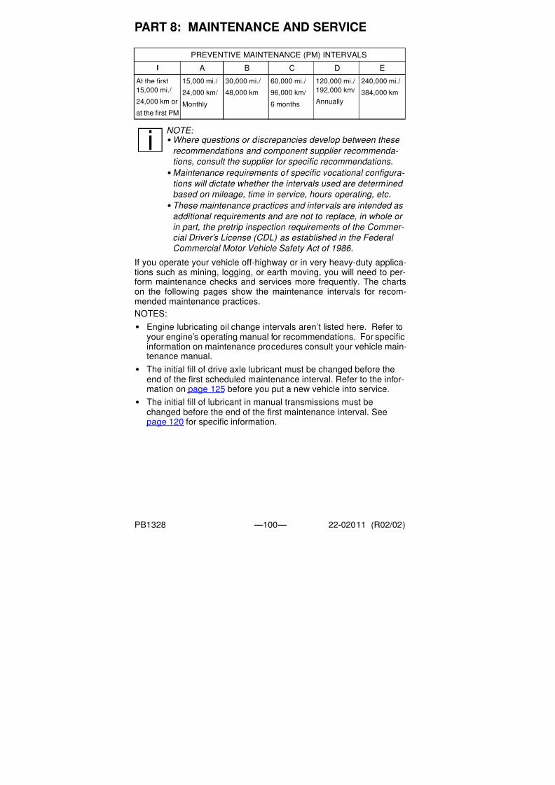
7/31/2019 Peterbilt Model 387 Operators Manual
http://slidepdf.com/reader/full/peterbilt-model-387-operators-manual 102/188
PART 8: MAINTENANCE AND SERVICE
PB1328 —100— 22-02011 (R02/02)
If you operate your vehicle off-highway or in very heavy-duty applica-tions such as mining, logging, or earth moving, you will need to per-form maintenance checks and services more frequently. The chartson the following pages show the maintenance intervals for recom-mended maintenance practices.
NOTES:
• Engine lubricating oil change intervals aren’t listed here. Refer toyour engine’s operating manual for recommendations. For specific
information on maintenance procedures consult your vehicle main-tenance manual.
• The initial fill of drive axle lubricant must be changed before theend of the first scheduled maintenance interval. Refer to the infor-mation on page 125 before you put a new vehicle into service.
• The initial fill of lubricant in manual transmissions must bechanged before the end of the first maintenance interval. Seepage 120 for specific information.
PREVENTIVE MAINTENANCE (PM) INTERVALS
I A B C D E
At the first
15,000 mi./
24,000 km or
at the first PM
15,000 mi./
24,000 km/
Monthly
30,000 mi./
48,000 km
60,000 mi./
96,000 km/
6 months
120,000 mi./
192,000 km/
Annually
240,000 mi./
384,000 km
NOTE: •Where questions or discrepancies develop between these
recommendations and component supplier recommenda-
tions, consult the supplier for specific recommendations.
•
Maintenance requirements of specific vocational configura- tions will dictate whether the intervals used are determined
based on mileage, time in service, hours operating, etc.
•These maintenance practices and intervals are intended as
additional requirements and are not to replace, in whole or
in part, the pretrip inspection requirements of the Commer-
cial Driver’s License (CDL) as established in the Federal
Commercial Motor Vehicle Safety Act of 1986.

7/31/2019 Peterbilt Model 387 Operators Manual
http://slidepdf.com/reader/full/peterbilt-model-387-operators-manual 103/188
P B 1 3 2 8
—1 0 1 —
2 2 - 0 2 0 1 1 ( R 0 2 / 0 2 )
*
SYSTEM COMPONENT MAINTENANCE TASK
Frame Fifth Wheel Check the kingpin lock and plate for wear and fu
(NLGI #2 grease).
Frame Fasteners Check for tightness; tighten to the specified torq
required (see page 163).
Crossmembers and
Mounting Brackets
Inspect for cracks and loose fasteners. Replace
specified torque value as required (see page 16
Front Axle Steering knuckles, thrust
bearings, kingpins,
drawkeys, tie rod ends,
steering stops, & bushings
Inspect for wear and damage and for endplay. S
required (see page 161).
Kingpin bushings & tie rod
ball ends
Lubricate with approved grease.
Total Vehicle Alignment Check and adjust as required.
Front
Suspension
Front Spring Inspect for cracked leaves, worn bushings, & ex
Spring Pins & Shackles Inspect for worn parts and excessive joint cleara
replace as required.

7/31/2019 Peterbilt Model 387 Operators Manual
http://slidepdf.com/reader/full/peterbilt-model-387-operators-manual 104/188
P B 1 3 2 8
—1 0 2 —
2 2 - 0 2 0
1 1 ( R 0 2 / 0 2 )
FrontSuspension Spring Pins Lubricate.
Shock Absorbers Inspect for leaking, body damage, and damaged
ings. Replace as required.
Shock Absorbers Check for proper function.
U-bolts (ON HIGHWAY) Check the general condition and the tightness of
the nuts to the specified torque value as required
U-bolts (OFF HIGHWAY) Check the general condition and the tightness of
the nuts to the specified torque value as required
Drive Axle
(Dana)
Axle Housing Visually inspect for damage or leaks.
Axle Housing Check oil level. Check “cold.” Torque the drain p
Axle Housing Drain the lubricant while warm. Flush each unit w
oil. Change the lubricant.
Air Shift Unit Check the lubricant level.Air Shift Unit Remove the housing cover and drain the lubrican
thoroughly and dry in air.
SYSTEM COMPONENT MAINTENANCE TASK

7/31/2019 Peterbilt Model 387 Operators Manual
http://slidepdf.com/reader/full/peterbilt-model-387-operators-manual 105/188
P B 1 3 2 8
—1 0 3 —
2 2 - 0 2 0 1 1 ( R 0 2 / 0 2 )
Drive Axle
(Dana)
Breather Clean or replace.
Lube Pump (ON HIGHWAY) Remove the magnetic strainer and inspect for w
Wash in solvent and dry in air.
Lube Pump (OFF HIGH-
WAY)
Remove the magnetic strainer and inspect for w
Wash in solvent and dry in air.
Lube Filter (ON HIGHWAY) Change.Lube Filter (OFF HIGH-
WAY)
Change.
Magnetic drain plug and
breather (ON HIGHWAY)
Clean or replace.
Magnetic drain plug and
breather (OFF HIGHWAY)
Clean or replace.
Drive Axle
(Meritor)
Axle Housing Check the “cold” fill level at the differential carrieangle of less than 7 degrees, or at the axle bowl
angle of greater than 7 degrees. Tighten the plug
(47 - 68 N.m.)
Axle Housing Visually inspect for damage or leaks.
SYSTEM COMPONENT MAINTENANCE TASK

7/31/2019 Peterbilt Model 387 Operators Manual
http://slidepdf.com/reader/full/peterbilt-model-387-operators-manual 106/188
P B 1 3 2 8
—1 0 4 —
2 2 - 0 2 0
1 1 ( R 0 2 / 0 2 )
Drive Axle(Meritor) Axle Housing Drain and replace the lubricant.
Lubricant filter Change the filter.
Breather Check the operation. If the cap doesn’t rotate fre
Input shaft & pinion shaft Check and adjust the endplay.
Axle shaft Tighten the rear axle flange nuts to the specified
Interaxle differential Check the operation.
Rear
Suspension
U-bolts Check the torque. Tighten to specified torque va
(see page 161).
Frame & crossmember
bolts
Check the torque. Tighten to specified torque va
(see page 163).
Mounting brackets and
fasteners
Check the condition and the fastener torque. Tig
fied torque value as required (see page 163).
Brakes Brake lining Inspect; replace as required.
Slack adjusters Check the push rod travel and check the control
Adjust at reline (see page 129).
Slack adjusters Lubricate (NLGI #2 grease).
SYSTEM COMPONENT MAINTENANCE TASK

7/31/2019 Peterbilt Model 387 Operators Manual
http://slidepdf.com/reader/full/peterbilt-model-387-operators-manual 107/188
P B 1 3 2 8
—1 0 5 —
2 2 - 0 2 0 1 1 ( R 0 2 / 0 2 )
Brakes Brake camshaft bearing Lubricate (NLGI #2 grease).
Brake treadle valve Clean the area around the treadle, boot, and mo
Check the pivot and mounting plate for integrity.
plunger boot for cracks. Lubricate roller pin, pivo
(NLGI #2 grease).
Brake treadle valve Rebuild through an authorized Peterbilt service f
Brake air system Check air lines and fittings for leaks (see page 12
as required to reduce chafing. Check tank mounti
Brake air system Clean or replace the inline filters.
Hub,
Drum, &
Hubcap
Hubs (non-LMS) Check the bearing endplay and adjust as require
Hubs (non-LMS) with out-
runner seals
Clean the components and check for excessive
Change the oil and seal (see page 127).
Hubs (non-LMS) with
standard seals
Clean the components and check for excessive
Change the oil and seal (see page 127).
Hub seals (all) Check for leaks; replace as required.
SYSTEM COMPONENT MAINTENANCE TASK

7/31/2019 Peterbilt Model 387 Operators Manual
http://slidepdf.com/reader/full/peterbilt-model-387-operators-manual 108/188
P B 1 3 2 8
—1 0 6 —
2 2 - 0 2 0
1 1 ( R 0 2 / 0 2 )
Hub,Drum, &
Hubcap
LMS Hubs (Dana) Check the bearing endplay and adjust as require
LMS Hubs (Dana) with
Synthetic Lubricant
Clean the components and check for excessive w
Change the oil and seal (see page 127).
LMS Hubs (Dana) with
Mineral Lubricant
Clean the components and check for excessive w
Change the oil and seal (see page 127).
Brake drums Inspect for visible cracks, heat checking, galling
braking surface, and for severe corrosion on the
Check for out-of-round or oversize condition [0.0
more than the original diameter]. Replace as req
Hubcaps Clean the sight window. Check the center plug, m
and fill plug for leaks and for proper installation. R
damaged parts. Check the lubricant level and ad
Main &
auxiliarytransmission
Main & auxiliary transmis-
sion and transfer case
Inspect for visible damage, signs of overheating,
Main & auxiliary transmis-
sion and transfer case
Check the drain plugs for tightness.
SYSTEM COMPONENT MAINTENANCE TASK

7/31/2019 Peterbilt Model 387 Operators Manual
http://slidepdf.com/reader/full/peterbilt-model-387-operators-manual 109/188
P B 1 3 2 8
—1 0 7 —
2 2 - 0 2 0 1 1 ( R 0 2 / 0 2 )
Main &
auxiliary
transmission
Oil cooler Clean the fins (air-to-oil type) and body. Check t
and for leaks; replace as required.
Main &
auxiliary
transmis-
sion (Dana)
Main & auxiliary transmis-
sion
Check the oil level; refill as required (see page 1
Main &auxiliary
transmis-
sion
(Dana)
Main & auxiliary transmis-sion (ON HIGHWAY)
Drain the lubricant while warm. Flush each unit woil.
Main &
auxiliary
transmis-
sion
(Dana)
Main & auxiliary transmis-
sion (OFF HIGHWAY)
Drain the lubricant while warm. Flush each unit w
oil.
Main &auxiliarytransmission(Meritor)
Transfer Case Check the oil level; refill as required (see page 1
SYSTEM COMPONENT MAINTENANCE TASK

7/31/2019 Peterbilt Model 387 Operators Manual
http://slidepdf.com/reader/full/peterbilt-model-387-operators-manual 110/188
P B 1 3 2 8
—1 0 8 —
2 2 - 0 2 0
1 1 ( R 0 2 / 0 2 )
Main &auxiliarytransmission(Meritor)
Transfer Case Drain lubricant while warm. Flush each unit with
Main &auxiliarytransmission(ZFMeritor)
Freedomline Transmis-
sion
Change the oil (see page 124).
Air Intake Air intake piping, mount-ing, and charge air cooler Check the system for broken pipes, leaks, joint inness, and proper support (see page 166).
Engine air intake tubing Disassemble, clean, check for cracks, leaks, and
Cold starting aids Check for leaks and proper operation (see page
Air cleaner Replace the element as indicated (see page 166
Clutch Clutch pedal shaft Check for excessive looseness and lubricate (NL
Clutch pedal Check for proper free pedal (see page 146).
Clutch release linkage Check for excessive looseness and lubricate (NL
Clutch release bearing Lubricate.
SYSTEM COMPONENT MAINTENANCE TASK

7/31/2019 Peterbilt Model 387 Operators Manual
http://slidepdf.com/reader/full/peterbilt-model-387-operators-manual 111/188
P B 1 3 2 8
—1 0 9 —
2 2 - 0 2 0 1 1 ( R 0 2 / 0 2 )
Clutch Clutch release shaft Lubricate.
Cooling Hoses Check the radiator and heater hoses for leaks.
System Flush, drain, and refill with new coolant mix (see
System Check concentration of antifreeze solution and co
(see page 143).
System Change coolant filter; add conditioner and suppl
additives (SCAs) (see page 143).
Fan clutch housing Check for leaks (see page 166).
Tires &
Wheels
Tires Check inflation pressure (see page 133).
Tires Inspect for cuts, irregular wear, missing lugs, side
Disc wheels Inspect the wheel disc for any cracks or surface
Inspect the rim edge and bead seat area for damdamaged wheels - DO NOT ATTEMPT TO REPA
Demountable rims Inspect the mounting ring, rim gutter, side ring, a
damage; replace as required.
SYSTEM COMPONENT MAINTENANCE TASK

7/31/2019 Peterbilt Model 387 Operators Manual
http://slidepdf.com/reader/full/peterbilt-model-387-operators-manual 112/188
P B 1 3 2 8
—1 1 0 —
2 2 - 0 2 0
1 1 ( R 0 2 / 0 2 )
Tires &Wheels Wheel nuts and studs Check the tightness of the fasteners and tighten the specified torque as required (see page 139).
Wheel nuts and studs Inspect for damaged hex corners, stripped or da
and excessive corrosion; clean or replace as req
Power
Steering
Reservoir Check the fluid level (see page 128).
Reservoir (ON HIGHWAY) Drain, replace the filter, and refill (see page 128)
Reservoir (OFF HIGHWAY) Drain, replace the filter, and refill (see page 128)Steering gear Check the lash of the sector shaft; adjust as requ
Steering gear Grease the trunnion bearing (EP NLGI #2 lithium
filled, HD grease).
Steering gear Grease the input shaft seal (EP NLGI #2 lithium-
filled, HD grease).
Power assist cylinder Lubricate the ball joints. Inspect for leaking rod s
ball joint boots, and damage to cylinder rod or ba
Hoses and tubes Check for leaks and chafing.
Steering linkage Check all joints for excessive lash; replace as re
161).
SYSTEM COMPONENT MAINTENANCE TASK

7/31/2019 Peterbilt Model 387 Operators Manual
http://slidepdf.com/reader/full/peterbilt-model-387-operators-manual 113/188
P B 1 3 2 8
—1 1 1 —
2 2 - 0 2 0 1 1 ( R 0 2 / 0 2 )
Power
Steering
Draglink tube clamp and
ball socket
Check the torque; tighten to specified torque val
Pitman arm clamp bolt
and nut
Check the torque; tighten to specified torque val
Steering intermediate shaft Check the torque on the pinch bolt and nut.
Steering intermediate shaftU-joints (ON HIGHWAY)
Lubricate [EP NLGI #2 HD grease, +325° F to -1-23° C) range].
Steering intermediate shaft
U-joints (OFF HIGHWAY
or CITY DELIVERY)
Lubricate [EP NLGI #2 HD grease, +325° F to -1
-23° C) range].
Draglink and tie rod arm ball
sockets (ON HIGHWAY)
Lubricate (EP NLGI #2 lithium-based, moly-filled
Steering intermediate shaft
U-joints (OFF HIGHWAYor CITY DELIVERY)
Lubricate (EP NLGI #2 lithium-based, moly-filled
Fuel &
Tanks
Fuel tanks Inspect tanks, brackets, hoses, and fittings for cor
ness, abrasion damage, and leaks; repair or repla
SYSTEM COMPONENT MAINTENANCE TASK

7/31/2019 Peterbilt Model 387 Operators Manual
http://slidepdf.com/reader/full/peterbilt-model-387-operators-manual 114/188
P B 1 3 2 8
—1 1 2 —
2 2 - 0 2 0
1 1 ( R 0 2 / 0 2 )
Fuel &Tanks Fuel tank breathers Check for proper function; clean the drain hoses
Fuel tank straps Tighten to proper torque value of 45 - 70 Lb. ft. (61
annually once strap tension reaches a steady state
retorquings, the measured torque is the same as p
Fuel tank steps Check for snug fit of side plates against tank andCheck for damaged or broken steps, missing bolgrommet between tank and side plate. Replace aged parts and adjust for fit as required.
Driveshafts Models 1610-1810 & SPL-
90 slip member & U-joints
Lubricate.
Model SPL-100 slip mem-
ber & U-joints
Lubricate.
Models SPL-140/140HD/
170/170HD/250/250HD
slip members & U-joints
Lubricate.
Models SPL-140XL/
170XL/250XL slip mem-
bers and U-joints (ON
HIGHWAY & LINE HAUL)
Lubricate.
SYSTEM COMPONENT MAINTENANCE TASK

7/31/2019 Peterbilt Model 387 Operators Manual
http://slidepdf.com/reader/full/peterbilt-model-387-operators-manual 115/188
P B 1 3 2 8
—1 1 3 —
2 2 - 0 2 0 1 1 ( R 0 2 / 0 2 )
Driveshafts Models SPL-140XL/
170XL/250XL slip mem-
bers and U-joints (OFF
HIGHWAY & CITY)
Lubricate.
Battery
Boxes, Tool
Boxes, and
Steps
Battery cables Check the condition of the cables, cushion clamp
Replace a cushion clamp if the rubber has deterio
tighten terminals, and secure cables to prevent ch
damaged cables (cuts, cracks, or excessive wear
Batteries Check for cracks and damage, electrolyte level,
nals, and tightness of holddowns (see page 147
Battery box and tray Check the box integrity. Clean the drain tube and
leaks. Check condition of all equipment mounted
Electrical &
lights
Headlamps Check the aim and adjust as required.
Warning lights in light bar Check at the ignition start position to verify bulbs
page 42).
Turn signal Visual check.
Stop lights Visual check.
SYSTEM COMPONENT MAINTENANCE TASK

7/31/2019 Peterbilt Model 387 Operators Manual
http://slidepdf.com/reader/full/peterbilt-model-387-operators-manual 116/188
P B 1 3 2 8
—1 1 4 —
2 2 - 0 2 0
1 1 ( R 0 2 / 0 2 )
Electrical &lights Reverse lights Visual check.
Alternator Check operation and output.
Alternator Check tightness of the pulley nut.
Alternator Check the tension of the drive belt (see page 164
Alternator Check tightness of the terminal hex nuts.
Starter Check torque on hex nuts.
ECM connector Check the tightness of the ECM connector.Wheel sensors Check for damaged sensors and connectors, and w
Fuel tank sending unit Check the mounting screws and electrical conne
damaged wires and connectors.
Power supply harnesses
(engine, transmission, etc.)
Check for worn or damaged insulation, corroded
wires, and oil or fluid leaks on the connectors or
Power supply harnesses
(engine, transmission, etc.)
Wash to remove excess grease.
Cab struc-
ture, doors,
& hoods
Hood Lubricate the lower hood pivot (only if lube fitting
SYSTEM COMPONENT MAINTENANCE TASK

7/31/2019 Peterbilt Model 387 Operators Manual
http://slidepdf.com/reader/full/peterbilt-model-387-operators-manual 117/188
P B 1 3 2 8
—1 1 5 —
2 2 - 0 2 0 1 1 ( R 0 2 / 0 2 )
Cab, doors,
& hoods
Hinges and latch Lubricate with silicone spray.
Body & cab holddown bolts Check the condition and tightness.
Tilt pump Check the oil level; refill as required.
Cab tilt system Check for hydraulic leaks.
Heating &
Air Condi-
tioning
Air conditioner Operate the system. (NOTE: The air conditioning
when the Defrost/Defog mode is selected.)
Heater & air conditioner Perform the checks listed on page 169.
Cab air filter Clean; replace after a maximum of three cleanin
Heater & air conditioner Full operational and diagnostic check.
Exhaust System Check for leaks and proper support (see page 1
Air Air compressor governor Replace air strainer.
Air lines Check condition and routing to prevent chafing.
System Lubricate (see page 141).
Inline filters Replace elements or clean with solvent.
SYSTEM COMPONENT MAINTENANCE TASK

7/31/2019 Peterbilt Model 387 Operators Manual
http://slidepdf.com/reader/full/peterbilt-model-387-operators-manual 118/188
P B 1 3 2 8
—1 1 6 —
2 2 - 0 2 0
1 1 ( R 0 2 / 0 2 )
Air Air dryer Perform the checks listed on page 143.Air dryer (ON HIGHWAY) Overhaul.
Air dryer (OFF HIGHWAY) Overhaul.
Engine Basic Engine The maintenance and service interval recommend
specific engine are the maintenance requirements
engine manufacturer’s Operations and Maintenan
included with the vehicle. Strict adherence to thestions is required to maintain warranty coverage. T
and service interval recommendations for the eng
cantly, depending on the manufacturer and the mo
As a minimum, perform the operations listed belo
Fuel filter Drain, clean, and refill or replace as required (see
Bypass oil filter Clean filter and change element.
Block Clean with steam or solvent.
Crankcase breather Clean.
Manifold nuts Tighten to specified torque.
Oil pan Capscrew Tighten to specified torque.
SYSTEM COMPONENT MAINTENANCE TASK

7/31/2019 Peterbilt Model 387 Operators Manual
http://slidepdf.com/reader/full/peterbilt-model-387-operators-manual 119/188
P B 1 3 2 8
—1 1 7 —
2 2 - 0 2 0 1 1 ( R 0 2 / 0 2 )
Engine Drive pulleys Check for tightness.
Turbocharger Check manifold and mounting.
Radiator shutters Check controls.
All lines and seals Check for leaks.
Mounts Check for tightness.
Fan hub Lubricate; check for air leaks. If vehicle is not equ
filter/dryer, check the inline filter to the fan hub (se
SYSTEM COMPONENT MAINTENANCE TASK

7/31/2019 Peterbilt Model 387 Operators Manual
http://slidepdf.com/reader/full/peterbilt-model-387-operators-manual 120/188
PART 8: MAINTENANCE AND SERVICE
PB1328 —118— 22-02011 (R02/02)
Lubricant Specifications
In this section you will find the basic information you need to do theroutine lubrication your vehicle requires. Of course you will want toschedule service more frequently if you are operating under severeconditions such as extreme heat or cold, with very heavy loads, off-road, etc. For any special service requirements, consult your servicemanuals and your lubricant supplier. And please remember: one keyto keeping your truck running at top economy and in prolonging its life
is proper lubrication servicing. Neglecting this essential aspect ofvehicle care can cost time and money in the long run.
Master Lubrication Index
Lubricant Symbol Key
BB: Ball Bearing grease
CB: Engine oil for mild to moderate requirements
CC/CD: Engine oil for severe requirements (MIL-L-2104B / MIL-L-45199B w/ 1.85% max. sulfated ash content)
CD: Engine oil meeting API “Five engine test sequence”
CD50: SAE 50W synthetic transmission fluid
CE: Engine oil meeting severe duty service requirements fordirect-injection turbocharged engines.
CL: Multipurpose chassis grease
C4: Type C4 transmission fluid (torque fluid)
EP: Extreme Pressure Lubricant
GL: Straight mineral gear lubricant
HD: Hypoid Gear Oil, A.P.I. - GL-5, SAE 80W-90
HT: High Temperature grease (Timken Spec. 0-616)MP: Multipurpose gear lubricant (MIL-L-2105B)
WB: Wheel Bearing grease (Timken Spec. 0-610)
WARNING! Handle lubricants carefully. Vehicle lubricants
(oil and grease) are poisonous and can cause sickness.
They can also damage the paint on the vehicle.
CAUTION: Do not mix different types of lubricants. Mixing
lubricants (oil and grease) of different brands or types
could damage vehicle components; therefore, drain (or
remove) old lubricants from the unit before refilling it
NOTE: The responsibility for meeting these specifications,
the quality of the product, and its performance in service
rests with the lubricant supplier.

7/31/2019 Peterbilt Model 387 Operators Manual
http://slidepdf.com/reader/full/peterbilt-model-387-operators-manual 121/188
PART 8: MAINTENANCE AND SERVICE
PB1328 —119— 22-02011 (R02/02)
Component Lubrication Index
Component Lubricant
Universal Joints EP
Drive Shaft Splines CL
Wheel Bearings (driven hubs) HD
Wheel Bearings (nondriven hubs) CD50
Wheel Bearings (all grease-lubri-
cated hubs)
WB
Steering Column CL
Alternator Bearing BB*Fan Hub BB*
Power Steering Reservoir C4
Steering Drag Link CL
Steering Knuckles CL
Spring Pins CL
Clutch Release Bearings BB
Brake Shoe Anchor Pins HT
Brake Cam Bearings HT
Slack Adjusters CL
Starter Bearings CC
Turbocharger Aneroid CC
Water Pump BB*
Cab Tilt Hydraulic Reservoir Hydraulic Jack Oil, MIL-L-5056B
Speedometer Cables Lubriplate Aero or equivalent
*Consult manufacturer or lubricant supplier for special details.
02942

7/31/2019 Peterbilt Model 387 Operators Manual
http://slidepdf.com/reader/full/peterbilt-model-387-operators-manual 122/188
PART 8: MAINTENANCE AND SERVICE
PB1328 —120— 22-02011 (R02/02)
Engine
Proper engine lubrication depends on the outside temperatureswhere you will be driving. Use the oil recommended for the condi-
tions you are most likely to be facing. You will find a complete enginelubrication service guide in the Engine Operation Manual that camewith your vehicle. There, the engine manufacturer explains more fullyall the maintenance operations that you — and a qualified servicemechanic — need to perform on your engine.
Fuller Transmission Lubrication
Fuller transmissions are designed so that the internal parts operate ina bath of oil circulated by the motion of gears and shafts. Grey ironparts have built-in channels where needed to help lubricate bearingsand shafts. All parts will be amply lubricated if these procedures areclosely followed:
1. Maintain oil level; check it regularly.
2. Change oil regularly.
3. Use the correct grade and type of oil.
4. Buy oil from a reputable dealer.
WARNING! Exhaust fumes from the engine contain carbon monoxide, a colorless and odorless gas. Do not breathe the engine exhaust gas. A poorly maintained, damaged or cor- roded exhaust system can allow carbon monoxide to enter
the cab or sleeper. Entry of carbon monoxide into the cab is also possible from other vehicles nearby. Failure to properly maintain your vehicle could cause carbon monoxide to enter the cab/sleeper and causes serious illness.
CAUTION: Never idle your vehicle for prolonged periods of time if you sense that exhaust fumes are entering the cab or sleeper. Investigate the cause of the fumes and correct it as soon as possible. If the vehicle must be driven under
these conditions, drive only with the windows slightly open. Failure to repair the source of the exhaust fumes may lead to personal harm.
NOTE: Keep the engine exhaust system and the vehicle’s cab/
sleeper ventilation system properly maintained. It is recommended
that the vehicle’s exhaust system and cab/sleeper be inspected
• By a competent technician every 15,000 miles
• Whenever a change is noticed in the sound of the
exhaust system
• Whenever the exhaust system, underbody, cab or
sleeper is damaged

7/31/2019 Peterbilt Model 387 Operators Manual
http://slidepdf.com/reader/full/peterbilt-model-387-operators-manual 123/188
PART 8: MAINTENANCE AND SERVICE
PB1328 —121— 22-02011 (R02/02)
Lubrication Change and Inspection
Highway Use
• Refer to the Eaton Fuller transmission manual for service information.
• Refer to the oil change vs. temperature chart that follows for spe-cial oil change information. The “intermittent peak temperature” isthe maximum temperature observed for a short time in a fullyloaded vehicle performing normally.
Recommended Lubricants
CAUTION: Exceeding the recommended oil change intervals may be harmful to the life of the transmission and the transmission oil cooler.
Type Grade(SAE)
AmbientTemperature
Heavy Duty Engine OilMIL-L-2104B, C, D;
50 Above 10° F (-12° C)
API - SF, or API-CD(Previous API desig-
nations acceptable)
40 Above 10° F (-12° C)
30 Below 10° F (-12° C)
Mineral gear oil withrust and oxidationinhibitor API-GL-1
90 Above 10° F (-12° C)
80W Below 10° F (-12° C)
Synthetic Lubricant* 50 All
* See your Peterbilt dealer for approved brands.
02944

7/31/2019 Peterbilt Model 387 Operators Manual
http://slidepdf.com/reader/full/peterbilt-model-387-operators-manual 124/188
PART 8: MAINTENANCE AND SERVICE
PB1328 —122— 22-02011 (R02/02)
Spicer Transmission Lubrication
It is extremely important to use the proper lubricants and maintain thecorrect oil levels in Spicer units. This will ensure proper lubrication
and operating temperatures in these units.Recommended Lubricants
The lubricants listed below are recommended, in order of preference,for use in all Spicer mechanical transmissions, auxiliaries, and trans-fer cases. Do not use extreme pressure additives such as those foundin multipurpose or rear axle-type lubricants. These additives are notrequired in Spicer transmissions, and may in some cases createtransmission problems. Multipurpose oils, as a group, have relatively
poor oxidation stability, a high rate of sludge formation, and a greatertendency to react with or corrode the steel and bronze parts.
TypeGrade
(SAE)
Ambient
Temperature
Heavy Duty Engine Oil MIL-L-2104D
or MIL-L-46152B, API-SF or API-CD
(MIL-L-2104B or C or MIL-L-46152
designations are acceptable)
30, 40, or 50 Above 0° F
(-18° C)
30 Below 0° F
(-18° C)
Mineral gear oil
(R & O type) API-GL-1
90 Above 0° F
(-18° C)
80 Below 0° F
(-18° C)
Synthetic Engine Oil meeting
MIL-L-2104D or MIL-L-46152B,
API-SF or API-CD
CD50
CD30
All
*Synthetic Gear Oil Meeting
MIL-2105C or API-GL5
EP75W90
EP75W140
All
*EP Gear Oils are not recommended when lubricant operating temperatures
are above 230° F (110° C).

7/31/2019 Peterbilt Model 387 Operators Manual
http://slidepdf.com/reader/full/peterbilt-model-387-operators-manual 125/188
PART 8: MAINTENANCE AND SERVICE
PB1328 —123— 22-02011 (R02/02)
Oil Changes
An initial oil change and flush should be performed after the transmis-sion has been placed in actual service. This change should be madeany time after 3000 miles (4800 km) but never longer than 5000 miles(8000 km) of over-the-road service. In off-highway use, the changeshould be made after 24 hours but before 100 hours of service haveelapsed.
Refilling
Remove all dirt around filler plug. Refill with new oil of the grade rec-ommended for the existing season and prevailing service. Fill to thebottom of the level testing plug positioned on the side of the transmis-sion. Do not overfill the transmission. Overfilling usually results in oilbreakdown due to excessive heat and aeration from the churningaction of the gears. Early breakdown of the oil will result in heavy var-nish and sludge deposits that plug up oil ports and build up on the
splines and bearings. Overflow of oil can also escape onto clutch orparking brakes. When adding oil, do not mix different types of oil.
CAUTION: When adding oil, types and brands of oil should
not be intermixed because of possible incompatibility,
which could decrease the effectiveness of the lubrication or cause component failure.

7/31/2019 Peterbilt Model 387 Operators Manual
http://slidepdf.com/reader/full/peterbilt-model-387-operators-manual 126/188
PART 8: MAINTENANCE AND SERVICE
PB1328 —124— 22-02011 (R02/02)
Meritor Transmission Lubrication
Lubrication Change and Inspection
• An initial oil change and flush should be performed after the trans-
mission has been in service for 5000 miles (8000 km).
• Refer to the Meritor Transmission manual for service information.
Recommended Lubricants
Type Of Lubricant Grade (SAE)Ambient
Temperature
Heavy-Duty Engine OilA.P.I.-CD, -CE, -SF or
-SG (Previous A.P.I. desig-
nations acceptable)*
MIL-L-2104B, C, or D*
50 Above 10° F (-12° C)
40 Above 10° F (-12° C)
30 Below 10° F (-12° C)
Mineral Gear Oil with Rust
and Oxidation Inhibitor,
A.P.I.-GL-1*
90 Above 10° F (-12° C))
80 Below 10° F (-12° C)
Synthetic Oil, Meritor Speci-
fication 0-81 *@
50 All
Cognis EMGARD lubricant# 50 All
* Multi-weight and EP gear oils are not recommended.
DO NOT MIX OILS IN THE TRANSMISSION.
@ See your Peterbilt dealer for Meritor-approved lubricant brands.
#
Freedomline transmission

7/31/2019 Peterbilt Model 387 Operators Manual
http://slidepdf.com/reader/full/peterbilt-model-387-operators-manual 127/188
PART 8: MAINTENANCE AND SERVICE
PB1328 —125— 22-02011 (R02/02)
Meritor Axle Lubrication
Under Meritor’s Advanced Lube Rear Drive Axle program, the axleslisted below are exempt from an initial lubricant change:
Meritor rear axles that do not appear on the list above will continue torequire an initial drain at 3000-5000 miles (4800-8000 km).
• Refer to the Meritor Field Maintenance Manual for a particular axlefor lubricant specifications.
• See your Peterbilt dealer for Meritor-approved lubricant brands.
• Refer to the following charts for lubricant change intervals:
• Change the lubricant filter every 120,000 miles (192,000 km). Top
off the lubricant level with a similar lubricant.
NOTE: Axles utilized in 100% off-highway use are not eligi-
ble for Meritor’s Advanced Lube Rear Drive Axle program.
AVAILABLE ADVANCED LUBE AXLES
RS-17-145 RS-23-180 RT-40-145 RT-44-145P
RS-19-145 RS-26-180 RT-40-145P RT-46-160
RS-21-145 RS-30-180 SQ-100A RT-46-160P
RS-23-160 RT-34-145 SQ-100AP RT-52-160
RS-23-161 RT-34-145P RT-44-145 RT-52-160P
Application Type Of Lubricant Mileage Interval
Linehaul Synthetic 240,000 Miles (384,000 km)
Synthetic with Pump
and Filter
500,000 Miles (800,000 km)
Mineral Base 120,000 miles (192,000 km)
City Delivery Synthetic 120,000 miles (192,000 km)
Synthetic with Pump
and Filter
240,000 Miles (384,000 km)
Mineral Base 120,000 miles (192,000 km)
Vocational Synthetic 120,000 miles (192,000 km)
Synthetic with Pump
and Filter
120,000 miles (192,000 km)
Mineral Base 120,000 miles (192,000 km)

7/31/2019 Peterbilt Model 387 Operators Manual
http://slidepdf.com/reader/full/peterbilt-model-387-operators-manual 128/188
PART 8: MAINTENANCE AND SERVICE
PB1328 —126— 22-02011 (R02/02)
Eaton/Dana Axle Lubrication
• The original mineral-based lubricant must be drained within 3000-
5000 miles (4800-8000 km) on all Eaton axles. This initial change
is very important because it flushes out break-in contaminants thatmight otherwise cause premature wear.
• No initial drain is required on Eaton axles that are factory filled with
an Eaton-approved synthetic lubricant.
• Mineral-based lubes must be drained within the first 5000 miles
(8000 km) if converting to an Eaton-approved synthetic lube.
• Change the lubricant within the first 5000 miles (8000 km) of oper-
ation after a carrier head replacement, regardless of the lubricanttype.
• Refer to the Eaton Field Maintenance Manual for a particular axle
for lubricant specifications.
• See your Peterbilt dealer for Eaton-approved lubricant brands.
• Refer to the chart on the next page for lubricant change interval.
Type ofLubricant On-HighwayMiles(km)
MaximumChangeInterval
On/Off HighwaySevere ServiceMiles (km)
MaximumChangeInterval
Mineral-Based 120,000
(192,000)
Yearly 60,000
(96,000)
Yearly
Eaton-Approved
Synthetic
240,000
(384,000)
2 Years 120,000
(192,000)
Yearly
Eaton-Approved
Synthetic in axlewith extended
drain interval
option
360,000
(576,000)

7/31/2019 Peterbilt Model 387 Operators Manual
http://slidepdf.com/reader/full/peterbilt-model-387-operators-manual 129/188
PART 8: MAINTENANCE AND SERVICE
PB1328 —127— 22-02011 (R02/02)
Wheel Bearing Lubrication
Oil-lubricated Driven Hubs
Use hypoid oil, A.P.I.-GL-5 SAE 80W-90 or equivalent. A minimum of1 quart (921 ml) of oil is required for proper lubrication of each drivehub. Add oil through the filler hole in the hub; if none, add oil throughthe differential filler hole. (Note: Remember to replace vent plug orthreaded filler plug when done.) Allow time for the oil to seep throughthe bearings when initially filling a hub. Maintain the differential oil levelby adding oil until its surface is even with the bottom of the filler hole (seepage 119).
Oil-lubricated Nondriven Hubs
Use CD50 synthetic transmission fluid SAE 50W or equivalent. A min-imum of 9 oz (270 ml) of lubricant is required for proper lubrication ofan LMS™ hub; 10 - 13 oz (295 - 400 ml) is required for a non-LMShub, depending on wheel design. Allow time for the fluid to seepthrough the bearings when initially filling a hub. When properly filled,the fluid level will lie between the fluid level line and 1/4” above theline. (Note: Remember to replace vent plug when done.)
Grease-Lubricated Hubs
Repack the hub bearing with clean wheel bearing grease after disas-sembling, cleaning, and inspecting.
Universal Joint Lubrication
Refer to the Spicer Universal Joints and Driveshafts service manualand lubrication specifications.

7/31/2019 Peterbilt Model 387 Operators Manual
http://slidepdf.com/reader/full/peterbilt-model-387-operators-manual 130/188
PART 8: MAINTENANCE AND SERVICE
PB1328 —128— 22-02011 (R02/02)
Steering Gear Lubrication
Inspection1. Check the fluid level; add fluid if required.
2. Check fluid for contamination, discoloration, or burnt smell; correct
source of such problems before replacing fluid & filter.
Replacement
1. Replace both the fluid and filter in accordance with the chart on
the next page. (Note: Do not mix different types of fluids)
2. Bleed the system if necessary.
*Extremely low temperatures may require lower viscosity fluids; con-sult your Peterbilt dealer for recommendations
@See TRW or Sheppard Service Manuals for additional fluid listings
Servicing Specific Systems And Units
This part will help you keep your Peterbilt vehicle in good running con-dition. There are a number of checks you can do, and you may be able
to do some of the service work yourself. But please: let your dealer’sservice department do any work you don’t have the tools or skill to per-form. Authorized service mechanics are trained in the proper technicaland safety procedures to fix your Peterbilt vehicle right.
CAUTION: When adding fluid, be sure to use fluid of the
same type. Do not mix different fluids. While many flu-
ids have the same description and intended purpose,
they should not be mixed due to incompatible additives.
If incompatible (insoluble) fluids are mixed in a power
steering system, air bubbles can be produced at the
interface of the two fluids. This can cause cavitation,
which reduces the lubrication between moving parts in
the gear. This could result in worn components.
SteeringGear
Fluid * Inspect[miles(km)]
Replace(miles/months)
TRW Type C-4 Fluid Every 15,000
(24,000)
Every 240,000
(384,000)/24
Sheppard Type C-4 Fluid Every 15,000
(24,000)
Every 240,000
(384,000)/24

7/31/2019 Peterbilt Model 387 Operators Manual
http://slidepdf.com/reader/full/peterbilt-model-387-operators-manual 131/188
PART 8: MAINTENANCE AND SERVICE
PB1328 —129— 22-02011 (R02/02)
Brake Adjustment
To operate your vehicle safely and profitably, you need some under-standing of its brake systems. For more on brakes, see the Index,under Brakes. Brake adjustment and brake balance must be setcarefully to (1) make the most efficient use of the forces available forbraking and (2) allow equal stopping forces at all wheels.
Once a brake system is set to specifications, changing any one of itscomponents or any combination of components may cause the sys-tem to not work as well. All parts have to work together to perform as
they should.Any replacement components in your brake system should be exactlyequal to the original components. Any changes from the originalspecifications can affect the whole system.
All of the following areas are interrelated and must conform to originalspecifications:
•Tire Size •Brake Linings
•Cam Radius •Brake Chambers
•Wedge Angle •Slack Adjusters
•Drum Radius
WARNING! It is dangerous to work on a vehicle without
the right know-how and proper tools. You could be
badly injured, and you could damage the vehicle. Do
only work you know you are fully capable of doing, and for which you have the right tools.
WARNING! To prevent uncontrolled vehicle movement and
reduce risk of personal injury, park the vehicle on a hard
level surface, apply the parking brake, and chock all
wheels securely.
CAUTION: The air brake system of this vehicle was con-
figured for ONE of the following operations: tractor or
truck, and complies with the respective portions of
FMVSS 121. A tractor shall not be operated or config- ured as a truck, nor shall a truck be operated or config-
ured as a tractor, without significant modifications to
the air brake system in order to retain compliance with
FMVSS 121. Contact your Peterbilt dealer for instructions.
7/31/2019 Peterbilt Model 387 Operators Manual
http://slidepdf.com/reader/full/peterbilt-model-387-operators-manual 132/188
PART 8: MAINTENANCE AND SERVICE
PB1328 —130— 22-02011 (R02/02)
All vehicle operators should check their brakes regularly. Alwaysadjust your brakes when they are cool.
Perform the following checks and adjustments every 15,000 miles(24,000 km):
• Have brake linings inspected by a qualified mechanic for wear at
least every 15,000 miles. In severe service or off-highway applica-
tions inspect the linings more frequently.
• Check the air system for leaks:
1. Build up air pressure in the system to the governor cut-out point.
2. Stop the engine.
3. Release the parking brakes (push in the yellow knob).
4. Watch the rate of air pressure drop. The rate of drop should not be
more than 2 psi (14 kPa) per minute.
5. Now start the engine and build up the air pressure again.
6. Stop the engine. Ensure that the parking brakes are still released
(i.e., the yellow knob is pushed in).
7. Fully apply the service brakes.
8. Watch the rate of air pressure drop registered by the air gauge.
The rate of drop should not be more than 3 psi (21 kPa) per
minute.
9. If you find excessive leakage, a leakage test should be made at
the air line connections and at all air brake control units. To per-
form a leakage test, refer to the detailed instructions in the Peter-
bilt Maintenance Manual, or take your vehicle to an authorized
Peterbilt dealer.
Readjust the brakes if pushrod travel reaches 1 3/4 inches (44.4 mm)for steer axle brakes or 2 inches (51 mm) for rear axle brakes [2 1/4
WARNING! A nonconforming part in your brake system
could cause an accident. Sizes and types are so related
to one another that a seemingly unimportant change in
one may result in a change in how well your brakes work for you on the road. If parts don’t work together prop-
erly, you could lose control of your vehicle. Be sure any
replacement parts in your brake system conform exactly
to original specifications.
WARNING! Brake linings with a thickness below the speci-
fied minimum will have lining rivets exposed. Use of such
linings can damage the brake drum and also reduce brake efficiency, which could cause an accident or system failure.

7/31/2019 Peterbilt Model 387 Operators Manual
http://slidepdf.com/reader/full/peterbilt-model-387-operators-manual 133/188
PART 8: MAINTENANCE AND SERVICE
PB1328 —131— 22-02011 (R02/02)
inches (57 mm) for Type 36 chambers] at 80 - 90 psi (550 - 620 kPa)psi application pressure.
If you have manual slack adjusters:
• Adjust the slack adjuster until the brake is tight.
• Then back off two or three clicks until the shoes are just free. You
can determine this by spinning the wheel or tapping on the drumand listening for a clear ringing sound.
Normal pushrod travel is about 1 to 1 3/8 inch front and rear afterbrakes have been properly adjusted.
Correct Pushrod Travel
If you have automatic slack adjusters:Constant manual adjustment of automatic slack adjusters canshorten the life of your internal clutch. If proper stroke cannot bemaintained, replace the slack adjuster.
CAUTION: The brake adjuster alone does not ensure
proper brake operation. Inspect all brake components. All brake components work together and must be checked
periodically to ensure the brake system works properly.
See the Peterbilt Master Maintenance Manual for more
information on brake maintenance.
02945

7/31/2019 Peterbilt Model 387 Operators Manual
http://slidepdf.com/reader/full/peterbilt-model-387-operators-manual 134/188
PART 8: MAINTENANCE AND SERVICE
PB1328 —132— 22-02011 (R02/02)
Operational Checks of Automatic Slack Adjusters
• Measure brake chamber stroke with the spring brake released and
the air pressure at 100 psi (690 kPa) minimum. Correctly installed
and functioning auto slack will produce the following strokes:-Type 36 chamber (rear brakes) should have a 1 1/2 inch to 2 1/4
inch (38 mm to 57 mm) stroke.
-Type 30 chamber (rear brakes) should have a 1 1/2 inch to 2 inch
(38 mm to 51 mm) stroke.
-Type 16, 20, & 24 chambers (front brakes) should have a 1 inch
to 1 3/4 inch (25.4 mm to 44.4 mm) stroke.
If the stroke exceeds the above specifications, check to verify that theslack adjuster is working.
• With the air system at 100 psi (690 kPa) or more, apply the brake.
If adjustment is necessary and the slack adjuster is working, theadjusting hex nut will rotate during the chamber return stroke. Install-ing a wrench on the hex nut will make this easier to see. On eachstroke after the first, the amount of adjustment and chamber travel willbe less.
Tires, Wheels, And RimsTires
Your tires are a very important part of your vehicle’s whole brakingsystem. How fast you can stop depends in large measure on howmuch friction you get between the road and your tires.
In addition, keeping your tires in good condition is essential to thesafe, efficient operation of your vehicle. Regular, frequent inspection
and the right care will give you the assurance of safe and reliable tireoperation. Here are some tips on maintaining your tires.
1. Underinflated Tires. Low pressure is a tire’s worst enemy. Under-inflation allows tires to flex improperly, causing high temperaturesto build up. Heat causes early tire damage such as flex break,radial cracks, and ply separation. Low pressure may affect controlof your vehicle, especially at the front wheels. Most tire wearproblems are caused by underinflation as the result of slow leaks,so you’ll want to check tire pressure regularly.
WARNING! Underinflated tires could cause a serious
accident. The extra heat caused by underinflation can
cause sudden tire failure. Low pressure may affect con-
trol at the front wheels. You could be seriously hurt in
an accident that could result. Keep your tires inflated to
the manufacturer’s recommended limit.

7/31/2019 Peterbilt Model 387 Operators Manual
http://slidepdf.com/reader/full/peterbilt-model-387-operators-manual 135/188
PART 8: MAINTENANCE AND SERVICE
PB1328 —133— 22-02011 (R02/02)
Checking Inflation Pressure
Give your tires a visual test every day, and check inflation with agauge every week.
• When checking tire pressure, inspect each tire for damage to side-walls, cuts, cracks, uneven wear, rocks between duals, etc. If a tireappears underinflated, check for damage to the wheel assembly.Don’t forget to check between dual wheels. If you find wheel dam-
age, have an expert tire service repair it.• Maximum tire pressure will be indicated on the sidewall of a tire.
• Check pressure only when the tires are cool. Warm or hot tirescause pressure buildup and will give you an inaccurate reading.So never deflate a warm tire to the specified pressure.
• Lower tire pressure does not give you more traction on ice orsnow. This is an old myth that refuses to die. Underinflation actu-ally reduces traction, steering control and tire load capacity.
2. Overloaded tires. Overloading your truck is as damaging to yourtires as underinflation. The following chart shows how neglect ordeliberate abuse can affect the life of your tires.
3. Overinflated tires. Too much air pressure reduces the tire tread
contact area and results in rapid wear in the center of the tread.
WARNING! You can be badly injured trying to fix tires.Don’t mount or dismount a tire yourself; have any wheel
service performed by an expert. And stand away from
the tire assembly while the expert is working.
EFFECT OF LOAD PRESSURE ON TIRE LIFE
Vehicle
Load
Normal 20%
Over
40%
Over
60%
Over
80%
Over
100%
Over
Tire
Pressure
Normal 20% Low 30% Low 35% Low 45% Low 55% Low
Expected
Total Tire
Mileage
Normal 70% 50% 40% 30% 25%
WARNING! Overinflated tires can cause accidents.They wear more quickly than properly inflated tires.And they are more subject to punctures, cracks, & other damage. They could fail and cause you to lose control of your vehicle. Be sure all tires are inflated correctly according to the manufacturer’s recommendations.
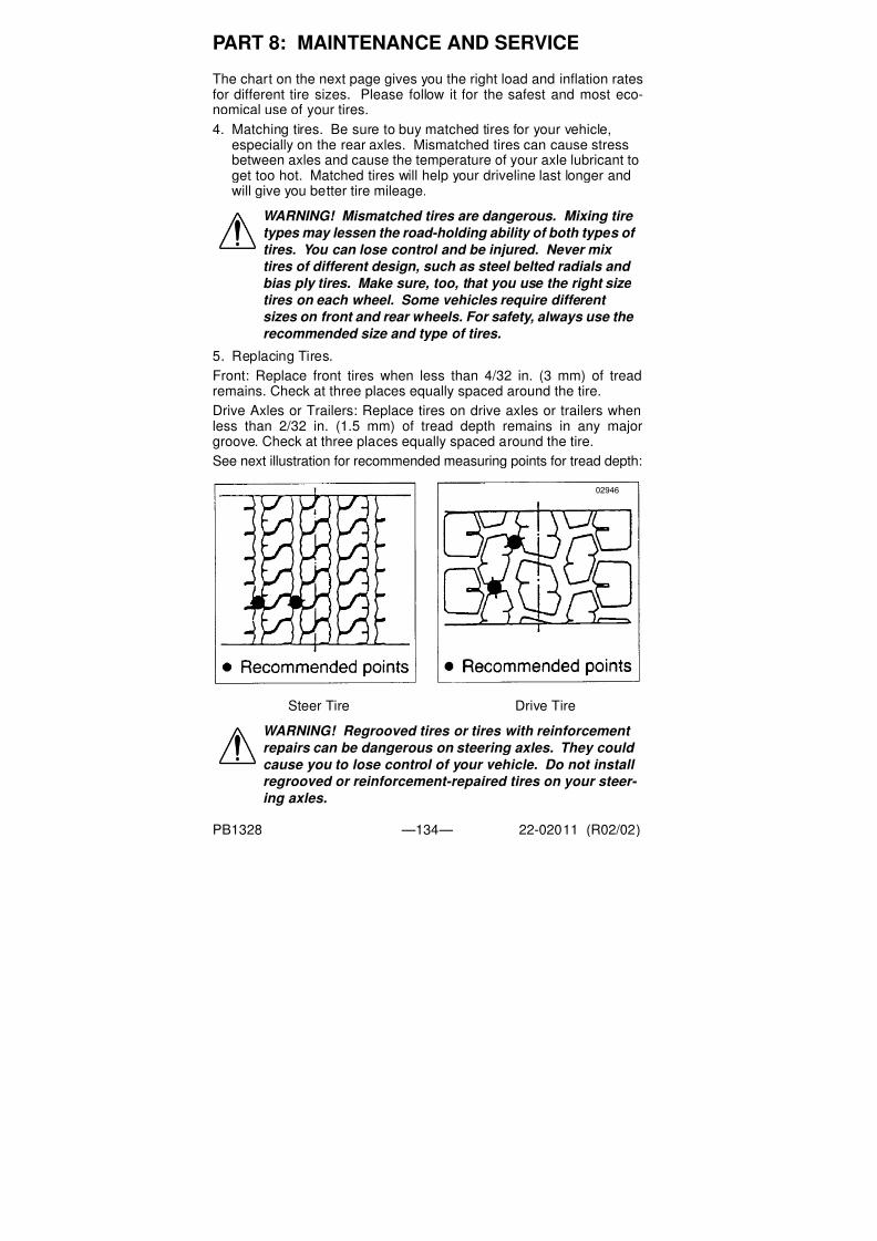
7/31/2019 Peterbilt Model 387 Operators Manual
http://slidepdf.com/reader/full/peterbilt-model-387-operators-manual 136/188
PART 8: MAINTENANCE AND SERVICE
PB1328 —134— 22-02011 (R02/02)
The chart on the next page gives you the right load and inflation ratesfor different tire sizes. Please follow it for the safest and most eco-nomical use of your tires.
4. Matching tires. Be sure to buy matched tires for your vehicle,especially on the rear axles. Mismatched tires can cause stressbetween axles and cause the temperature of your axle lubricant toget too hot. Matched tires will help your driveline last longer andwill give you better tire mileage.
5. Replacing Tires.
Front: Replace front tires when less than 4/32 in. (3 mm) of treadremains. Check at three places equally spaced around the tire.
Drive Axles or Trailers: Replace tires on drive axles or trailers whenless than 2/32 in. (1.5 mm) of tread depth remains in any majorgroove. Check at three places equally spaced around the tire.
See next illustration for recommended measuring points for tread depth:
Steer Tire Drive Tire
WARNING! Mismatched tires are dangerous. Mixing tire
types may lessen the road-holding ability of both types of
tires. You can lose control and be injured. Never mix
tires of different design, such as steel belted radials and
bias ply tires. Make sure, too, that you use the right size
tires on each wheel. Some vehicles require different
sizes on front and rear wheels. For safety, always use the
recommended size and type of tires.
WARNING! Regrooved tires or tires with reinforcement
repairs can be dangerous on steering axles. They could
cause you to lose control of your vehicle. Do not install
regrooved or reinforcement-repaired tires on your steer-
ing axles.
02946

7/31/2019 Peterbilt Model 387 Operators Manual
http://slidepdf.com/reader/full/peterbilt-model-387-operators-manual 137/188
PART 8: MAINTENANCE AND SERVICE
PB1328 —135— 22-02011 (R02/02)
6. Tire chains. If you need tire chains, install them on both sides of
each driving axle.
NOTE: To prolong your tires’ life and make them safer, have
their radial and lateral run-out checked at your dealer. And
of course you should have your tires balanced any time you
change a tire.
CAUTION: Chains on the tires of only one tandem axle
can damage the driveline U-joints and the interaxle differ-
ential. Your repairs could be costly & time-consuming.

7/31/2019 Peterbilt Model 387 Operators Manual
http://slidepdf.com/reader/full/peterbilt-model-387-operators-manual 138/188
P A R T 8 : MA I N T E N A N C E A N D
S E R V I C E
P B 1 3 2 8
—1 3 6 —
2 2 - 0 2 0 1 1
( R 0 2 / 0 2 )
T i r eL o a d an d I nf l a t i onT a b l e s
NOTE:
1. Pressure listed is the minimum for the load.
2. All tire load figures are in pounds.3. Figures in Bold face indicate maximum recommended load.Source: Bridgestone Tire 2/02
Load Range Letters and Corresponding Ply Rating
( G = 14 ply; H = 16 ply)
SINGLE RADIAL TIRES FOR VEHICLES IN HIGHWAY SERVICE
Tire
Size
Load
Range
Tire Load Limits At Various Cold Inflation Pressures (psi)
70 75 80 85 90 95 100 105 110 115 120
11R22.5 G 4530 4770 4990 5220 5510 5730 5950 6175
11R22.5 H 4530 4770 4990 5220 5510 5730 5950 6175 6320 6465 6610
11R24.5 G 4820 5070 5310 5550 5840 6095 6350 6610
11R24.5 H 4820 5070 5310 5550 5840 6095 6350 6610 6790 6970 7160
275 / 70R22.5 H 4850 5050 5250 5480 5705 5945 6195 6450 6720 7000
295 / 75R22.5 G 4500 4725 4940 5155 5370 5510 5780 5980 6175
285 / 75R24.5 G 4545 4770 4940 5210 5420 5675 5835 6040 6175
DUAL RADIAL TIRES FOR VEHICLES IN HIGHWAY SERVICE
11R22.5 G 4380 4580 4760 4950 5205 5415 5625 5840
11R22.5 H 4380 4580 4760 4950 5205 5415 5625 5840 5895 5950 6005
11R24.5 G 4660 4870 5070 5260 5510 5675 5840 6005
11R24.5 H 4660 4870 5070 5260 5510 5675 5840 6005 6205 6405 6610
275 / 70R22.5 H 4430 4610 4795 5005 5210 5430 5660 5890 6135 6395
295 / 75R22.5 G 4095 4300 4540 4690 4885 5070 5260 5440 5675
285 / 75R24.5 G 4135 4340 4540 4740 4930 5205 5310 5495 5675

7/31/2019 Peterbilt Model 387 Operators Manual
http://slidepdf.com/reader/full/peterbilt-model-387-operators-manual 139/188
PART 8: MAINTENANCE AND SERVICE
PB1328 —137— 22-02011 (R02/02)
Vehicle Loading
GVW: GVW is the Gross Vehicle Weight. This is the TOTALWEIGHT your vehicle is designed to carry. Never carry so heavy aload that you exceed the GVW rating of your Peterbilt vehicle.
Axle Weight: Your front and rear axles are rated according to the loadthey are designed to carry. You will find this number listed on thedriver’s door frame.
Load Distribution: Be sure any load you carry is distributed so that noaxle has to support more than its load limit.
WARNING! The components of your vehicle are
designed to provide satisfactory service if the vehicle is
not loaded in excess of either the gross vehicle weight rating (GVWR) or the maximum front and rear gross axle
weight ratings (GAWRs). Axle weight ratings are listed
on the driver’s door edge. Supervise all loading to
ensure that (1) the Gross Vehicle Weight Rating (GVWR)
is not exceeded and (2) the load is distributed correctly
so that the weight distribution is within the limits of the
front and rear axle load ratings. Severe damage to your
vehicle, difficult handling, or an accident could occur if your vehicle is not loaded properly.
WARNING! An unevenly distributed load or a load too heavy over one axle can affect the braking and handling of your vehicle and cause an accident. Even if your load is under the legal limits, be sure it is distributed evenly.
03002A
EXAMPLE
NOTE: Weight (Mass) inpounds (kilograms)

7/31/2019 Peterbilt Model 387 Operators Manual
http://slidepdf.com/reader/full/peterbilt-model-387-operators-manual 140/188
PART 8: MAINTENANCE AND SERVICE
PB1328 —138— 22-02011 (R02/02)
Hub Pilot Mount Ball Seat Mount
Hub, Drum, and Stud Assembly
Wheels
Wheel Nuts
The hub pilot mounting system uses
M22x1.5 metric threads (about 7/8
in. dia.). The stud stands out at least
1.9 in. beyond the brake drum. All
studs are right hand threads. Pilot
bosses machined on the hub fittightly to the wheel center bore.
The ball seat mounting uses 3/4 x 16
or 1 1/8 x 16 threads. The dual
mounting studs provide 1.3 - 1.44 in.
standout. Right hand and left hand
threads are required. Inner and outer
cap nuts center the wheels by seat-ing against wheel ball seats.
Pilot mount wheels have stud holes
that are reamed straight through (no
ball seats). Center bore diameter is 8
21/32 in. Budd Uni-Mount - 10
wheels have UNIMOUNT stamped
on the disc.
Ball seat wheels have spherical
chamfers machined on each stud
hole. Center bore diameter is
8 23/32 in.
Nut has a hex body and a flange for
clamping against wheel face. Hex
size is 33 mm (same as 1 5/16 in.).
Inner and outer cap nuts mate with
spherical chamfers on wheels. Inner
nut has 13/16 in. square end. Outer
nut has 1 1/2 in. hex.
WARNING! Mismatched wheel components are danger- ous. Equipment that does not exactly match original
specifications or that is mismatched could cause your
wheels to break and separate from the vehicle. The
resulting accident could be very serious. Each mounting
system is engineered for use only with its correct mating
part. Be sure properly matched components are used for
each type of mounting.
02949

7/31/2019 Peterbilt Model 387 Operators Manual
http://slidepdf.com/reader/full/peterbilt-model-387-operators-manual 141/188
PART 8: MAINTENANCE AND SERVICE
PB1328 —139— 22-02011 (R02/02)
Wheel Cap Nut Torque
At the first 100 miles, have all wheel cap nuts torqued to their speci-fied value. After that, check wheel cap nuts at least once a week.
Contact the Service Department at your dealership for information onthe proper installation procedure for the wheels on your truck. This isa job you may not be able to do yourself. You need the right torquingequipment to do it.
Wheel Bearing Adjustment
For safe, reliable operation and adequate service life, your wheelbearings must be checked and adjusted properly. The person bestequipped to do this is your authorized dealer’s service mechanic.
Disc WheelsTo check the torque on disc wheels, follow the crisscross sequencebelow. See the Specifications chart for proper torque specification.
Crisscross Sequence For Disc Wheels
Demountable Rims
To check the torque on demountable rims, follow the crisscrosssequence shown on the next page. See the Specifications chart forproper torque specification.
WARNING!
•Grooves in the wheel disc or other damage to the disc can lead to a serious accident. The disc will be weak- ened and can eventually come off, maybe causing you to lose control of your vehicle. Be sure to use the right
components and the right tools.•The end of the wheel wrench must be smooth. Burrs
on the end of the wrench can tear grooves in the disc,especially on aluminum wheels. These grooves may lead to cracks in the disc, and can cause it to fail.
02950

7/31/2019 Peterbilt Model 387 Operators Manual
http://slidepdf.com/reader/full/peterbilt-model-387-operators-manual 142/188
PART 8: MAINTENANCE AND SERVICE
PB1328 —140— 22-02011 (R02/02)
Crisscross Sequence For Demountable Rims
WARNING! Use only components marketed by PACCAR Parts. Use of non–original equipment could cause wheel breakage and wheel separation from vehi-
cle. Each mounting system is engineered only for use with its correct mating part. Be sure that properly matched components are used for each type of mount- ing. The comparison chart on page 138 illustrates the differences between parts used in hub–piloted mount and ball seat mount applications. Only PACCAR Parts supplied hub–piloted or ball–seat mounted wheels may be used on this vehicle.
•If you are not fully qualified and not equipped with the
proper tools and equipment, do not attempt to raise the vehicle or remove or install the damaged tire and wheel assembly. Obtain expert help. A person can be seriously injured and/or damage can result from using the wrong service methods. Truck tires and wheels should be serviced only by trained personnel using proper equipment. Do not reinflate a tire that has been run flat or is seriously low on air without first removing the tire from the rim and inspecting for damage.
•Follow OSHA regulations per section 1910.177.•Do not exceed the speed rating of tires. Exceeding the
speed rating may result in sudden tire failure and loss of vehicle control.
•Follow all warnings and cautions contained within the tire and wheel manufacturers literature.
•Only properly trained personnel should service tire and rim assemblies
02951

7/31/2019 Peterbilt Model 387 Operators Manual
http://slidepdf.com/reader/full/peterbilt-model-387-operators-manual 143/188
PART 8: MAINTENANCE AND SERVICE
PB1328 —141— 22-02011 (R02/02)
Your Vehicle’s Air System
CAP NUT TORQUE SPECIFICATIONS (R12/01)
WHEEL AND NUTCONFIGURATION STUD SIZE
TORQUES FOR INNER &
OUTER CAP NUTSLb. Ft. N.m
Stud-Piloted Disc
Wheels
3/4”-16 Inner
1 1/8”-16 Outer
450-500 610-680
Heavy Duty Stud-
Piloted Disc Wheels
15/16”-12 Inner
1 5/16”-12
Outer
750-900 1025-1225
PHP-10; Budd Uni-
Mount-10; WHD-8
M22 x 1.5-6H 450-500 610-680
Cast Spoke Wheel
Assembly
1/2” Dia.
5/8” Dia.
3/4” Dia.
Rim Clamp
Nut Torque
80-90 110-120
160-185 220-250
225-245 305-335
WARNING! Prior to the removal of any air system com-
ponent, always block and hold the vehicle by a secure
means other than the vehicle’s own brakes. Depleting
air system pressure may cause vehicle to roll. Keep
hands away from chamber push rods and slack adjust-
ers, they may apply as system pressure drops.
•After completing any repairs to the air system, always test for air leaks, and check the brakes for safe opera- tion before putting the vehicle in service.
•Never connect or disconnect a hose or line containing air pressure. It may whip as air escapes. Never remove a component or pipe plug unless you are certain all system pressure has been depleted.
•Never exceed recommended air pressure and always wear safety glasses when working with air pressure.
Never look into air jets or direct them at anyone.•Never attempt to disassemble a component until you
have read and understood recommended procedures.Some components contain powerful springs and injury can result if not properly disassembled. Use only proper tools and observe all precautions pertain- ing to use of those tools.

7/31/2019 Peterbilt Model 387 Operators Manual
http://slidepdf.com/reader/full/peterbilt-model-387-operators-manual 144/188
PART 8: MAINTENANCE AND SERVICE
PB1328 —142— 22-02011 (R02/02)
The operation of the vehicle’s braking system and many vehicleaccessories depends upon the storage and application of a high-pressure air supply.
Your vehicle’s compressor takes outside air and compresses it, usu-
ally to 100-120 psi. (690 - 1380 kPa). The compressed air then goesto the reservoirs to be stored until needed. When you operate your airbrakes, the stored compressed air flows into the chambers where it isused to apply your truck and trailer brakes. That is why, when youpush down on your brake pedal, you don’t feel the same amount ofpressure on the pedal that you do when you apply the brakes on yourcar. All you are doing on your truck is opening an air valve to allow airto flow into the brake chambers.
Air Supply System
Contamination of the air supply system is the major cause of prob-lems in air-operated components such as brake valves, wiper motors,and suspension height control valves. To keep contaminants to thelowest possible level, follow these maintenance procedures.
Daily
• Drain moisture from the supply and service air tanks.
• Operate air devices to circulate lubricants within the unit.
Periodically
• Clean filter screens ahead of the valves by removing the screensand soaking them in solvent. Blow them dry with pressurized airbefore reinstalling them.
Twice a Year
• Add approximately 1/4 oz. (7.5 ml) of light viscosity lubricant to theair line leading to the wiper motor. Acceptable lubricants are DowCorning 200 fluid, 200 CS viscosity, and Sprague Wiper Lube. Ifyou have alcohol dryers installed in the air system, the alcohol canwash away lubricants from the wiper motors.
• Maintain the air compressor to prevent excessive oil by-pass. Seeyour shop manual for maintenance details.
• Replace worn seals in valves and air motors as they are needed.
WARNING! If the supply and service tanks are not drained at the recommended frequency, water could be sent to all air lines and valves. This could cause corrosion, which could compromise the brake system safety and potentially
cause an accident.
CAUTION: Don’t use penetrating oil, brake fluid, or wax-
based oils in the air system. These fluids may cause
severe damage to air system components.

7/31/2019 Peterbilt Model 387 Operators Manual
http://slidepdf.com/reader/full/peterbilt-model-387-operators-manual 145/188
PART 8: MAINTENANCE AND SERVICE
PB1328 —143— 22-02011 (R02/02)
Air Dryer
Every 900 operating hours or 30,000 miles/48,000 km or 3 months,
check for moisture in the air brake system by opening reservoirs,
drain cocks, or valves and checking for the presence of water. A table-
spoon of water in a reservoir would point to the need for a desiccant
cartridge change. However, the following should be considered first:
• Air usage is exceptionally high/abnormal for a highway vehicle.
This may be due to accessory air demands or some other unusual
air requirement that doesn’t allow the compressor to load/unload
in a normal fashion or it may be due to excessive leaks in the air
system.
• When more than a 30-degree F (17-degree C) range of tempera-
ture occurs in one day, small amounts of water can accumulate in
the air brake system due to condensation. Under these condi-
tions, the presence of small amounts of moisture is normal and
should not be considered as an indication that the dryer is not per-
forming properly.
• An outside air source may have been used to charge the air sys-
tem, in which case this air did not pass through the drying bed.
Engine Cooling System
What to Add to Your Cooling System
Water
Water must be clean & free of corrosive and scale-forming chemicals.Your drinking water may not be good for your vehicle. Approved addi-tives help neutralize water’s harmful effects on your cooling system.Ask your dealer to recommend the best ones for you.
NOTE: A small amount of oil in the system may be normal and
should not, by itself, be considered reason to replace a desic-
cant cartridge; oil-stained desiccant can function adequately.
WARNING! Removing the radiator cap on a hot engine
can cause scalding coolant to spray out and burn you
badly. If the engine has been in operation within the pre-
vious 30 minutes, be very careful in removing the radia- tor cap. Protect face, hands, and arms against escaping
fluid and steam by covering the cap with a large, thick rag.
If you see any steam or coolant escaping, don’t try to
remove it until the radiator cools down. If you see noth-
ing escaping, still remove the cap very slowly and care-
fully. Be ready to back off if any steam or coolant begins
to escape.

7/31/2019 Peterbilt Model 387 Operators Manual
http://slidepdf.com/reader/full/peterbilt-model-387-operators-manual 146/188
PART 8: MAINTENANCE AND SERVICE
PB1328 —144— 22-02011 (R02/02)
If the cooling system in your truck has a treated spin-on water filter,install the service filter on all B checks. See the Preventive Mainte-nance Schedule in this manual. For more detailed recommendationscheck with the service department at your dealership or check the
engine manufacturer’s operation and maintenance manual.If, in an emergency, the radiator was filled with water known to containgypsum, sulfur, or chlorine:
1. Drain the cooling system as soon as possible.
2. Flush the system.
3. Replace the filters.
4. Refill with premixed coolant. Consult your maintenance manual
for the correct filters to install.Low Silicate Antifreeze
Always install a low silicate antifreeze. Premix your coolant to main-tain the correct proportion of antifreeze and coolant conditionerchemicals. Install only enough low silicate antifreeze to provide the
required protection against freezing.The chart on the next page shows the temperature protection pro-vided by low silicate ethylene glycol antifreeze in relation to the pro-portion mixed with water.
Antifreeze Mixture: A 53% mixture of low silicate antifreeze with 47%water is sufficient for year-round normal operation. This will normallyprotect your engine from freezing and boil-over. Note in the chart that100% antifreeze is no more effective than a 30% mixture.
Some Tips about Additives:
• If you add supplemental coolant additives to your radiator, main-
tain them at the recommended levels. Read the label carefully.
Too much additive could harm your vehicle.
WARNING! Handle coolant and antifreeze carefully. Ethyl-
ene glycol antifreeze is poisonous. Store in original fluid
container only, and always keep out of reach of children.
Antifreeze
(percent by
volume)
0 10 20 30 40 50 53 57 60 68 70 80 90 100
Temp.
Protec-tion
Deg
C
0 -4 -9 -16 -24 -36 -40 -46 -53 -68 -65 -49 -35 -16
Deg
F
+32 +24 +16 +4 -12 -34 -40 -50 -63 -92 -85 -57 -31 +4
NOTE: Never exceed a 64/36 antifreeze/water mix ratio, it
will increase the risk of silicate drop-out. Additionally, it may not increase antifreeze protection, and it could decrease it.

7/31/2019 Peterbilt Model 387 Operators Manual
http://slidepdf.com/reader/full/peterbilt-model-387-operators-manual 147/188
PART 8: MAINTENANCE AND SERVICE
PB1328 —145— 22-02011 (R02/02)
• Antifreeze solutions containing antileak additives may quickly
restrict your water filter. If this happens, your filter won’t work. So
stay away from antileak additives.
•Don’t add rust inhibitors, radiator sealants, or water pump lubri-cants containing soluble oil to the coolant. These additives can
cause the anticorrosion chemicals not to work.
Topping Up (For a Standard or Low Flow System)
With the engine cold, top up with premixed coolant. Add the coolantthrough the pressure cap neck on the surge tank. The surge tank ison the firewall. For the proper level, see illustration on next page.
Refilling Your Radiator
1. Be sure the radiator and engine block drains are closed.
2. Move the heater control to maximum heat position.
3. Remove the surge tank pressure cap..
Surge Tank
4. Through the surge tank, fill the system with premixed coolant.Pour it in a steady flow until the radiator is full.
5. Start the engine.
6. Idle at low RPM.
7. Complete the filling. Do it as quickly as possible.
CAUTION: Never install 100% antifreeze for top-up cool-
ant. It could damage your vehicle.
NOTE: If frequent topping up is necessary and there are no
visible signs of coolant leaks when the engine is cold, check
for leaks with the engine operating at normal operating tem-
perature.
Cap
03003A
Sight Gauge

7/31/2019 Peterbilt Model 387 Operators Manual
http://slidepdf.com/reader/full/peterbilt-model-387-operators-manual 148/188
PART 8: MAINTENANCE AND SERVICE
PB1328 —146— 22-02011 (R02/02)
8. Idle the engine until it reaches normal operating temperature.
9. Fill the radiator as necessary to raise the coolant level to theproper level. Replace the surge tank pressure cap.
Check the coolant level after each trip when the engine has cooled.Add coolant as necessary. You may find your coolant level is not upto the correct level soon after you have filled the radiator. This may bebecause all the trapped air in the system has not yet been purged. Ittakes a little time for all the air to leave the system after you fill yourradiator.
Transmission And Drive Train
Clutch Adjustment
Clutch pedal free travel is usually 1 3/4 in. to 2 in. (34 to 51 mm). Thisshould be your guide for determining whether your truck needs clutchadjustment. Some vehicles have automatic clutch adjustment. If yoursdoesn’t have this feature, adjustment will have to be done by a trainedcertified mechanic. Have the adjustment done before clutch pedalfree travel is reduced to the minimum allowable 1/2 in. (13 mm).
NOTE: Do not overfill a cooling system. Excess coolant may result in overflow, loss of antifreeze, and reduced corro- sion protection. For a cold engine, the proper coolant level is
1 in. below the radiator cap seal. For an operating engine at normal temperature, coolant should be even with the radia- tor cap seal.

7/31/2019 Peterbilt Model 387 Operators Manual
http://slidepdf.com/reader/full/peterbilt-model-387-operators-manual 149/188
PART 8: MAINTENANCE AND SERVICE
PB1328 —147— 22-02011 (R02/02)
Battery Care
WARNING! Batteries contain acid that can burn and gas- ses that can explode. Ignoring safety procedures can
cause you or others to be badly hurt.•Never jump start a battery near fire, flames, or electrical
sparks. Batteries generate explosive gases. Keep sparks, flame, and lighted cigarettes away from batteries
•Do not allow battery fluid to contact eyes, skin, fabrics,or painted surfaces. Always wear eye protection. Bat- tery acid that may spill during charging should be washed off with a solution of warm water and baking soda to neutralize the acid. If you accidentally get acid in your eyes or on your skin, immediately rinse with cold water for several minutes and call a doctor.
•Be careful that metal tools or any metal in contact with the positive terminal do not contact the positive battery terminal and any other metal on the vehicle at the same time. Remove metal jewelry; avoid leaning over a battery..
•If metal jewelry or other metal comes in contact with electrical circuits, a short circuit may occur causing you to be injured—plus electrical system failure and dam- age to the vehicle.
•
Do not try to jump start or charge a frozen battery.(Even a battery with ice particles on the electrolyte sur- face is dangerous.) Allow it to thaw out first. And always allow battery to thaw gradually—do not apply direct heat. Gas trapped in the ice may cause an explosion.
•Do not try to jump start a vehicle if the electrolyte level in the battery of either vehicle is low. Maintain the full level of electrolyte in the batteries. This reduces the vol- ume of gas in the cells.
•The voltage of the booster battery must have a 12–volt
rating. And the capacity of the booster battery should not be lower than that of the discharged battery. Use of batteries of different voltage or substantially different capacity rating may cause an explosion. To avoid seri- ous personal injury and damage to the vehicle, heed all warnings and instructions of the jumper cable manufac- turer. The jumper cables must be long enough so that the vehicles do not touch.
•Applying a higher voltage booster battery will cause expensive damage to sensitive electronic components,such as relays, and the radio. Improper hook–up of jumper cables or not following these procedures can damage the alternator or cause serious damage to both vehicles or yourself.
•Battery posts, terminals, and related accessories con- tain lead and lead compounds, chemicals known to the State of California to cause cancer and reproduc- tive harm. Wash hands after handling.

7/31/2019 Peterbilt Model 387 Operators Manual
http://slidepdf.com/reader/full/peterbilt-model-387-operators-manual 150/188
PART 8: MAINTENANCE AND SERVICE
PB1328 —148— 22-02011 (R02/02)
Regular attention to the charging system will help prolong the servicelife of your batteries. Here are some common causes of battery failure:
• Overcharge: This condition may result from improper voltage regu-lator adjustment. It results in overheating of the battery, warpedplates, and evaporation of electrolyte.
• Undercharge: Your voltage regulator may be malfunctioning or isimproperly adjusted, the drive belt is slipping, or your vehicle hasundergone long periods of standing idle or short distance driving.
These conditions result in battery plates becoming covered with ahard coating.
• Vibration: Loose battery hold-downs may cause battery plate failure.
• Short Circuits: These discharge a battery by draining electricity.
• Dirty or Loose Connections: Bad connections may stop the flow ofelectrical power to and from the battery.
Recharging Batteries
Except for using small trickle chargers to maintain battery condition,
you should have your vehicle’s batteries charged by a qualified ser-vice facility. To help reduce the risk of personal injuries, follow theseguidelines carefully when recharging a battery:
• Before attempting any service in the electrical installation, discon-nect the battery negative cable.
• Allow no sparks or open flame anywhere near the charging area.
• Charge a battery only in a well-ventilated area, such as outdoors orin a fully open garage which contains no pilot lights or other flames.
• Always make sure the battery charger is OFF before connecting or
disconnecting the cable clamps.
CAUTION: Departures from these procedures could also cause serious damage to both vehicles. Improper use of a booster battery to start a vehicle may cause an explosion.
WARNING! A battery contains gas that is explosive and flammable. It could injure you severely. A spark or flame near a battery on charge may cause it to explode with great force. Follow these guidelines carefully when recharging a battery:
WARNING! Always make sure the battery charger is OFF
before connecting or disconnecting the cable clamps. Do
not connect or disconnect charger cables while the
charger is operating to reduce the danger of explosions.
WARNING! Always shield your eyes and avoid leaning over
the battery whenever possible.

7/31/2019 Peterbilt Model 387 Operators Manual
http://slidepdf.com/reader/full/peterbilt-model-387-operators-manual 151/188
PART 8: MAINTENANCE AND SERVICE
PB1328 —149— 22-02011 (R02/02)
• Use protective eyewear.
\
• Maintain the full level of electrolyte in the batteries. This reduces thevolume of gas in the cells. The electrolyte level should always bebetween 0.4–0.6 in. (10–15 mm) above plates. Fill with distilledwater only. After distilled water has been added, wait at least a halfhour to measure solution density (specific gravity). The specific gravityshould be between 1.258–1.265 or the electrolyte level within “MIN”
and “MAX” marks.• Before attempting any work on the batteries or electrical system,
remove all jewelry. If metal jewelry or other metal comes in contactwith electrical circuits, a short circuit may occur causing you to beinjured—plus electrical system failure and damage.
• To avoid short circuits and damage to yourself or the vehicle, neverplace metal tools or jumper cables on the battery or nearby. Metal thataccidentally comes in contact with the positive battery terminal or anyother metal on the vehicle (that is in contact with the positive terminal),
could cause a short circuit or an explosion.• Keep all batteries away from children.
• Never reverse battery poles.
• Battery terminals should not be coated with improper grease. Use
petroleum jelly or commercially available, noncorrosive, noncon-ducting terminal coatings.
• Keep the battery clean and dry.
• Look for any signs of damage.
• Battery acid that may spill during charging should be washed offwith a solution of warm water and baking soda to neutralize theacid. If you accidentally get acid in your eyes or on your skin,immediately rinse with cold water for several minutes and call a
doctor.• Do not charge a frozen battery; allow it to thaw out first. And
always allow the battery to thaw gradually—do not apply directheat. Gas trapped in the ice may cause an explosion.
• Never attempt to place the vehicle in motion, or run the engine withbatteries disconnected.
• When fast charging, remove the battery caps so pressure doesn’taccumulate.
CAUTION: Never use a metallic funnel to add distilled
water. It could come in contact with a terminal, creating a
short circuit, resulting in severe injury or damage to your
vehicle.
WARNING! Charger cables must be connected positive to
positive (+ to +) and negative to negative (– to –). Reversing
polarity can damage the electrical system.

7/31/2019 Peterbilt Model 387 Operators Manual
http://slidepdf.com/reader/full/peterbilt-model-387-operators-manual 152/188
PART 8: MAINTENANCE AND SERVICE
PB1328 —150— 22-02011 (R02/02)
• Never use a fast charger as a booster to start the engine. This canseriously damage sensitive electronic components such as relays,radio, etc., as well as the battery charger. Fast charging a batteryis dangerous and should only be attempted by a competent
mechanic with the proper equipment.
Slow Battery Charging
1. Make sure the electrolyte level in each cell is between the “MIN”
and “MAX” marks. If the fluid level is below the “MIN” mark, correctthe condition.
2. Disconnect the battery cables.
3. Connect charger cables.
4. Start charging the battery at a rate not over 6 amperes. Normally,a battery should be charged at no more than 10 percent of itsrated capacity.
5. After charging, turn OFF charger and disconnect charger cables.
Jump Starting BatteriesIf your battery is discharged (dead), you may be able to start it byusing energy from a good battery in another vehicle. This is termed“jump starting.”
Because of the various battery installations in optional electrical sys-tems, Peterbilt does not recommend that you attempt to jump startyour vehicle. If you have a battery problem, contact a Peterbilt Dealeror a reputable towing service. But if you are unable to do this, andmust jump-start your vehicle, then ensure that you follow the precau-
tions and instructions below.
To Jump Start Your Vehicle:
1. Wear eye protection and remove rings, metal watch bands, andany other metal jewelry.
2. Set the parking brakes. Place the transmissions of both vehicles inNeutral. Do not let the vehicles touch one another. Turn the ignitionkey to Off in the vehicle with the discharged battery. Also turn offlights, heater, and any other unnecessary electrical load.
3. If either battery has vent caps, remove them and check the fluidlevel. If it is OK, replace the caps before going further. If the level islow, add distilled water, and replace the caps before proceeding. Ifno water is available, remove the caps and cover the filler open-ings with a cloth before proceeding. After jump starting the vehicle,dispose of the cloth.
NOTE: Follow the instructions that come with your battery
charger. It is not necessary to remove the battery from the
compartment.

7/31/2019 Peterbilt Model 387 Operators Manual
http://slidepdf.com/reader/full/peterbilt-model-387-operators-manual 153/188
PART 8: MAINTENANCE AND SERVICE
PB1328 —151— 22-02011 (R02/02)
4. Attach one end of a jumper cable to the dead battery’s positive ter-minal. This will have a large red “+” or “P” on the battery case,post, or clamp. Attach the other end of the same cable to the posi-tive terminal of the good battery.
5. Attach the remaining jumper cable FIRST to the negative batteryterminal (black “-” or “N”) of the good battery, and then to the chas-sis or ground of the vehicle being jump started.
6. Start the engine in the vehicle with the good battery. Let it run afew minutes. Then start the engine in the vehicle with the deadbattery. If the engine fails to start, do not continue to crank the starterbut contact the nearest Authorized Service Center.
7. Reverse the above sequence exactly when removing the jumpercables. Take care that your first step is to remove the cable fromthe chassis or ground of the vehicle that was jump-started.
Removing and Installing Batteries
Whenever you have to install a battery or remove one, follow theseguidelines for the safety of yourself and the battery.
• Ensure all switches on the vehicle are turned Off.
• Disconnect the ground cable first when removing a battery.
• Connect the ground cable last when installing a battery.
Electrical System
WARNING! If you do not cover the filler openings on the battery, electrolyte could boil out of the openings and hurt someone or damage the vehicle. Replace caps securely if there is enough fluid in the battery, or cover with a cloth if no water is available and your fluid is low.
WARNING! When disconnecting jumper cables, make sure
they do not get caught in any moving parts in the engine
compartment.
CAUTION: Always reinstall the battery compartment cover
(step) before entering the cab. Without the battery cover you
could slip and fall, resulting in possible injury to yourself.
CAUTION: Do not modify or improperly repair the vehicle’s
electrical system or power distribution box. All electrical repairs should be performed by a qualified service techni-
cian. Improper repair or modifications will void your war-
ranty and/or cause serious damage to your vehicle.

7/31/2019 Peterbilt Model 387 Operators Manual
http://slidepdf.com/reader/full/peterbilt-model-387-operators-manual 154/188
PART 8: MAINTENANCE AND SERVICE
PB1328 —152— 22-02011 (R02/02)
General
Four isolated power circuits are each controlled through a regionaldistribution or “load” center (see illustration below). These centers
contain relays and circuit protection/power distribution components:• Chassis load center (A) on the firewall in the engine compartment
on the passenger side
• Cab load center (B) behind the glove box on the passenger side
• Sleeper load center (C) in the baggage compartment under the
bunk on the passenger side
• Trailer load center (D) near trailer cable connection
Power to each center/circuit is fused via a Megafuse assembly (E) onthe front wall inside the battery box. Each power circuit has a dedi-cated fuse.
Key to load center and Megafuse assembly locations
A
B
C
D
E

7/31/2019 Peterbilt Model 387 Operators Manual
http://slidepdf.com/reader/full/peterbilt-model-387-operators-manual 155/188
PART 8: MAINTENANCE AND SERVICE
PB1328 —153— 22-02011 (R02/02)
Chassis Load Center
The chassis load center is located in the engine compartment on theright-hand (passenger) side of the firewall. It contains standard fuses
and relays controlling• chassis lighting •turn signals
• head lamps •engine functions
Illustration of Chassis Load Center
E T HE R
( OP T I ONA L )
E N GI NE
S T OP L A MP
I NP UT
E N G
F A N
DRL
DI S A B L E
RE V E R S E
L A MP
A / C
CL UT CH
HI B E A M
L H
HI B E A M
RH
F O G
DI S A B L E
DRL
L H
DRL
RH
F O G
RE L A Y
WA RNI N G: B RE A K E R S CA NN OT B E U S E D
I NMI NI F U S E L O CA T I ON
F A N
DRL
E N G
A / C
RE V
E T HE R
F UE L
DI M
A I R
I / M
F O G
F O G-2 0 A F O GL A MP
I / M- 5 A I NT E RF A CE M OD UL E
A I R-1 5 A A I RDRY E R
F UE L -1 5 A F UE L HE A T E R ( OP T I ONA L )
DI M- 5 A DI MME R S W
A / C-1 5 A A / C C OMP RE S S OR CL UT CH
E N G
-1 0 A E N GI NE I GNI T I ON
DRL -2 0 A DA Y T I ME R UNNI N GL I GHT S
F A N
-1 0 A E N GI NE F A N
RE V
-1 5 A RE V E R S E L A MP
E T HE
R-1 5 A E T HE R S T A RT ( OP T I ONA L )
W / W
-1 5 A WI P E RWA S HE R
W / W

7/31/2019 Peterbilt Model 387 Operators Manual
http://slidepdf.com/reader/full/peterbilt-model-387-operators-manual 156/188
PART 8: MAINTENANCE AND SERVICE
PB1328 —154— 22-02011 (R02/02)
Trailer Load Center
The trailer load center is located on the inside of the left-hand framerail near the air tank. It contains standard fuses and relays controlling
• trailer power• trailer ABS power
• trailer lighting protection
Illustration of Location of Trailer Load Center

7/31/2019 Peterbilt Model 387 Operators Manual
http://slidepdf.com/reader/full/peterbilt-model-387-operators-manual 157/188
PART 8: MAINTENANCE AND SERVICE
PB1328 —155— 22-02011 (R02/02)
Cab Load Center and Accessory Block
The cab load center (shown below) is located behind the glove com-partment. It is a printed circuit board containing relays and solid-state
circuit breakers controlling• cab lighting • radio/CB
• horn • wiper/washer and others
A separate accessory block contains fuses and relays and can beused to provide accessory power. Only the accessory block has ser-viceable parts.
Illustration of Cab Load Center
Sleeper Load Center and Accessory Block
The sleeper load center and accessory block (not shown) have thesame characteristics as the cab components. A sleeper load centercontrols
• sleeper lighting • load lights
• HVAC power and signal • fluorescent lightingA cab or sleeper load center also contains indicator lights that providediagnostic information:
• Green lights provide information about circuit power & ground.
• Red lights provide information about devices connected to a circuit.

7/31/2019 Peterbilt Model 387 Operators Manual
http://slidepdf.com/reader/full/peterbilt-model-387-operators-manual 158/188
PART 8: MAINTENANCE AND SERVICE
PB1328 —156— 22-02011 (R02/02)
Instructions for interpreting indicator light diagnostic information arelocated on the front cover of a load center.
Illustration of Front Cover of Cab Load Center

7/31/2019 Peterbilt Model 387 Operators Manual
http://slidepdf.com/reader/full/peterbilt-model-387-operators-manual 159/188
PART 8: MAINTENANCE AND SERVICE
PB1328 —157— 22-02011 (R02/02)
Megafuse Assembly
Power to each load center circuit is fused via a Megafuse assemblyon the front wall inside the battery box. Each power circuit has a ded-
icated fuse. Replacement fuses are available at auto parts stores.
Illustration of Megafuse Assembly in Standard Battery Box
Illustration of Megafuse Assembly in Back-of-Cab Battery Box

7/31/2019 Peterbilt Model 387 Operators Manual
http://slidepdf.com/reader/full/peterbilt-model-387-operators-manual 160/188
PART 8: MAINTENANCE AND SERVICE
PB1328 —158— 22-02011 (R02/02)
Diagnostics
Refer to the flowchart below to troubleshoot electrical problems andisolate faults.
WARNING! Attempting repair work without sufficient
training, service manuals, and the proper tools can be
dangerous. You could be injured or you could make your truck unsafe. Do only those tasks you are fully
qualified to do.
Identify the regional load center controlling the problem circuit.
For example•A chassis lighting issue would be controlled through the chassisload center.
•A sleeper tool box lighting issue would be controlled through thesleeper load center.
Is any device in or onthe chassis/trailer/cab/sleeper
getting power?
The fuse for theload center (locatedin the Megafillsassembly in thebattery box) hasblown. Replace thefuse, which is avail-able at an autoparts store.
NO
Chassis & Trailer Centers
•Check the fuses and relaysin the load center that con-trol the circuit for thedevice. Fuses & relays are
plug-in type.•Check the device for afaulty component (lamp,plug, in-line fuse, etc.)
Cab & Sleeper Centers
Interpret the diagnosticinformation being dis-played by the indicatorlights on the front cover of
the load center. Instructionsto do this are located on thefront cover.
YES YES

7/31/2019 Peterbilt Model 387 Operators Manual
http://slidepdf.com/reader/full/peterbilt-model-387-operators-manual 161/188
PART 8: MAINTENANCE AND SERVICE
PB1328 —159— 22-02011 (R02/02)
Headlamp Adjustment
Follow the procedure below to adjust a headlamp vertically.
1. On a suitable surface, make a horizontal aiming line the same
height above a level floor as is the optical center of a headlamp.
Optical Center
TORX #20
Vertical Adjustment
25 ft. (7.6 m)
Flat Wall
(NOTE: May not be the samefor every vehicle)
minimum aim distance
Wall or aim board to be painted flat white
No less than 2 ft. (0.6 m) above the aiming line14 ft. (4.3 m) long x 4 ft. (1.2 m) high (minimum size)
Aiming Line = Distance from level floorto optical center of headlamp

7/31/2019 Peterbilt Model 387 Operators Manual
http://slidepdf.com/reader/full/peterbilt-model-387-operators-manual 162/188
PART 8: MAINTENANCE AND SERVICE
PB1328 —160— 22-02011 (R02/02)
2. Park the vehicle as shown in the illustration with the headlamps on
in the low beam mode. Ensure that the vehicle is level.
3. Turn the vertical adjuster in each headlamp with a Torx head
wrench until the dark horizontal line visible in that headlamp’sbeam pattern is level (vertically) with the horizontal aiming line.
Fuel System
Location of Fuel Shut-off Valves: Fuel shut-off valves for the fuelcrossover line are on the bottom of the secondary fuel tank, at thecrossover line connection. They are optional on the primary fuel tank.
Specification: Use only diesel fuel as recommended by engine manu-facturers.
Fuel Filters
Please follow these recommendations when you are changing yourfuel filters or strainer elements. Your engine will run better and lastlonger if you do. See the engine manufacturer’s recommendations forproper water and micron requirements.
1. When removing filters, cover any electrical equipment and wiringthat might get soaked with fuel. Diesel fuel may permanently dam-
age electrical insulation.
2. When installing spin-on (throwaway) filters, hand tighten them only
to 1/2 to 2/3 turn after gasket contact. Mechanical tightening of
these filters may distort or crack the filter head.
3. When replacing a fuel filter element, don’t use a substitute. Install
only filter elements designed for fuel filtration. First clean and
inspect the shell. Then insert the new element and fill the con-
tainer at least 2/3 full of clean fuel before installing the shell.
4. Throw away old gaskets. Replace them with new ones to ensure a
positive seal.
WARNING! A mixture of gasoline or alcohol with diesel
fuel in the presence of an ignition source (such as a cig-
arette) could cause an explosion. You could be seri-
ously injured. Use only the recommended diesel fuel.
CAUTION: If anyone ever pours gasoline into your fuel
tank, drain the entire system. Otherwise, the pump and
engine will be damaged. Don’t try to dilute the gasoline by adding diesel fuel (See Warning above).
NOTE: To expel air from density-type strainer elements,
soak them in clean fuel before installing them.

7/31/2019 Peterbilt Model 387 Operators Manual
http://slidepdf.com/reader/full/peterbilt-model-387-operators-manual 163/188
PART 8: MAINTENANCE AND SERVICE
PB1328 —161— 22-02011 (R02/02)
5. Position the shell and gasket properly. Then tighten the cover nut
or bolt just enough to prevent fuel leakage.
6. After starting the engine, check for leaks around the filter.
Steering
Check:• Tierod for straightness
• Draglink clamp for looseness or interference
• Ball joints and steering U-joints for looseness
• Steering wheel for excessive freeplay. Check the simplest proba-
ble causes first:
-Unequal tire pressures
-Loose cap nuts
-Bent tierod
-Loose wheel bearing
If these checks do not reveal the problem, or if you correct them andstill have a steering problem, take your truck to an authorized dealerfor evaluation.
Front End Alignment
For driving safety and comfort, and to prolong the life of your vehicle,it is important to have proper front end alignment. Check tire wearfrequently. Uneven tire wear is a sign that your front end or rear axlesmay be misaligned.
If you see uneven wear, take your vehicle to a service center familiarwith aligning front ends on Peterbilt vehicles.
Rear Axle Alignment
Continual road shock and load stresses may force your rear axles outof alignment. If you detect rapid tire wear on the rear axles, you mayhave misaligned axles. If you suspect you do, have your rear axlealignment checked and adjusted by an authorized dealership.
U-Bolt Tension for Front and Rear Axles
It is important that U-bolts remain tight. Off-highway use of your vehi-cle will cause them to loosen faster. But all vehicles need to havetheir U-bolts checked and tightened regularly. Be sure someone with
WARNING! A steering system that is not working prop-
erly can cause an accident. You could lose control of
your vehicle if the steering is not in good order. For
driving safety, give your steering gear and components
the following visual checks frequently. Check them
especially after trips over rough roads.

7/31/2019 Peterbilt Model 387 Operators Manual
http://slidepdf.com/reader/full/peterbilt-model-387-operators-manual 164/188
PART 8: MAINTENANCE AND SERVICE
PB1328 —162— 22-02011 (R02/02)
the proper training and the right tools checks and tightens the U-boltson your Peterbilt. The proper torque requirements are specified in thePeterbilt Maintenance Manual for your vehicle.
WARNING! U-bolts that are too loose can cause an injury accident. Loose U-bolts can cause uneven tire
wear, poor alignment, and loss of control of your vehi-
cle. You probably can’t tighten U-bolts correctly your-
self. But be sure to have them checked and tightened
regularly by an authorized mechanic.
•For on-highway vehicles, tighten the U-bolts after the first 15,000 miles (24,000 km). Then tighten them every 60,000 miles (96,000 km) after that.
•For off-highway vehicles, tighten the U-bolts after the first day or two of operation. Then tighten them every 15,000 miles (24,000 km) after that.
WARNING! Failure to maintain the specified torque values
or to replace worn parts can cause component system fail-
ure, possibly resulting in an injury accident. Improperly
tightened (loose) suspension U–bolts can lead to unsafe
vehicle conditions, including: hard steering, axle misalign-
ment, spring breakage or abnormal tire wear.

7/31/2019 Peterbilt Model 387 Operators Manual
http://slidepdf.com/reader/full/peterbilt-model-387-operators-manual 165/188
PART 8: MAINTENANCE AND SERVICE
PB1328 —163— 22-02011 (R02/02)
Frame Fastener Torque Specifications
Standard Capscrew Torque Specifications
The torque values in the previous tables are based on the use ofclean and dry threads.
Fastener
Type
Fastener
Size
Torque
Lb. ft. N.m.
Bolt / Locknut /
Hardened Washer
1/2 Inch 86 - 108 117 - 147
5/8 Inch 130 - 163 176 - 221
M12 65 - 85 89 -115
M16 155 -195 210 - 264
M20 495 - 605 668 - 818
SAE Grade
Number 5 8
Capscrew Body
Size
(inches-thread)
Torque Torque
Lb. ft. N.m. Lb. ft. N.m.
1/4-20 6 - 9 8 - 12 9 - 12 12 - 16
-28 7 - 10 9.5 - 14 10 - 14 14 - 19
5/16-18 13 - 18 18 - 24 18 - 25 24 - 34
-24 14 - 20 19 - 27 20 - 28 27 - 38
3/8-16 22 - 32 30 - 43 31 - 44 42 - 60
-24 25 - 40 34 - 54 35 - 50 47 - 68
7/16-14 35 - 50 47 - 68 50 - 71 68 - 96
-20 39 - 56 53 - 76 56 - 80 76 - 108
1/2-13 54 - 77 73 - 104 76 - 109 103 - 149
-20 58 - 87 79 - 118 86 - 123 117 - 167
9/16-12 78 - 111 105 - 151 110 - 158 149 - 214
-18 87 - 124 118 - 168 123 - 176 167 - 239
5/8-11 108 - 154 147 - 209 153 - 218 208 - 296
-18 122 - 174 166 - 236 173 - 247 235 - 335
3/4-10 192 - 273 260 - 370 271 - 386 367 - 523
-16 214 - 305 290 - 414 303 - 431 411 - 583
7/8-9 309 - 441 419 - 598 437 - 624 593 - 846
-14 341 - 486 462 - 659 482 - 589 654 - 799
1 -8 464 - 662 629 - 898 656 - 935 889 - 1268
1-12 508 - 724 689 - 982 718 - 1023 973 - 1386

7/31/2019 Peterbilt Model 387 Operators Manual
http://slidepdf.com/reader/full/peterbilt-model-387-operators-manual 166/188
PART 8: MAINTENANCE AND SERVICE
PB1328 —164— 22-02011 (R02/02)
For standard capscrews:
1. Always use the torque values listed the capscrew table.
2. Reduce torque by 10% when engine oil is used as a lubricant.
3. Reduce torque by 20% if new plated capscrews are used.
Frame Fasteners
1. Go around your vehicle as per the Preventive Maintenance Sched-
ule and tighten all frame fasteners with a torque wrench.
2. Always use the torque values listed in frame fastener table.
3. Always torque fasteners from the nut end.
Engine Accessories
Accessory Drive Belts
You can extend the reliability and service life of your vehicle’s drivebelts with proper attention to installation, adjustment, and mainte-nance. Neglect could cause belt failure. The result could be the lossof the electrical or air system as well as possible engine damage fromoverheating. So it’s a very good idea to check your belts frequentlyand replace them as soon as you detect trouble.
Follow the procedure below to install an accessory drive belt:
1. Loosen the pulley bracket(s) and shorten the distance between the
pulley centers. Install the new belt without forcing it. Do not roll or
pry the belt over the pulley.
Pulley Brackets
CAUTION: When installing bolts on the frame, use only metric grade 10.9 bolts of the proper length.
02952

7/31/2019 Peterbilt Model 387 Operators Manual
http://slidepdf.com/reader/full/peterbilt-model-387-operators-manual 167/188
PART 8: MAINTENANCE AND SERVICE
PB1328 —165— 22-02011 (R02/02)
2. Check the pulley alignment and adjustment if necessary. Pulley
misalignment must not be more than 1/16 in. for each 12 inches of
belt free span (1.5 mm for each 300 mm of belt free span). Belt
free span is measured between pulley centers.
3. Check the riding depth. Belt riding depth should not vary more
than 1/16 in. (1.5 mm) on match belt sets.
4. Check that the belt does not ride on the bottom of the pulley
groove, and that the outside edge of the belt does not stick out
more than 1/16 in. (1.5 mm) beyond the outside edge of the pulley.
Belt Tension
Alternator drive belts (all widths), new or used, should be adjusted to105-125 pounds (467-566 N.) of tension.
The best method of testing belt tension is to apply a good qualitycommercial gauge. If a tension gauge is not available, use thismethod of testing:
• Apply 25 pounds (111 N.) of force midway between the pulleys.
• Deflection should be one belt thickness for each foot of distance
between the pulley centers.
Tension Test
Retensioning New BeltsA belt is considered “used” after 30 minutes of operation.
New belts will loosen after running for an hour or more. Check forproper tension after the first period of operation. If the belt can bedeflected 1/8 in. (3 mm) more than specified above, tighten accordingto the section above on belt tension. Do not tighten belts beyondspecified limits. Damage to bearings and the belts may occur.
NOTE: Engines equipped with poly-vee belts are equipped
with tensioners and therefore require no belt adjustments.
02953

7/31/2019 Peterbilt Model 387 Operators Manual
http://slidepdf.com/reader/full/peterbilt-model-387-operators-manual 168/188
PART 8: MAINTENANCE AND SERVICE
PB1328 —166— 22-02011 (R02/02)
Fan Clutch / Fan
To Check Your Fan:
1. Check the fan assembly mounting bolts for tightness. Inspect the
blades for damage.
2. Check the clutch operation by starting the engine when it is cold.
Then idle it at about 800 RPM. Listen for air leaks. Check that the
fan is not working while the engine is warming. When the clutch
engages, note the reading on the vehicle’s panel-mounted coolanttemperature gauge. If the fan clutch engages at low engine tem-
perature or cycles on and off more frequently than it should
(receives “false signals”), have the problem corrected at your deal-
ership.
Air Intake System
Engine heat, vibration, and age combine to loosen air intake connec-tions and cause cracks in the tubing and elbows. Leaks in the intakesystem allow abrasive dust to enter the engine and quickly causeexpensive damage. During your daily walk-around inspection, care-fully check all tubing, elbows, clamps, supports, and fasteners forcondition and tightness.
Under normal operating conditions, we recommend complete disas-sembly and cleaning of the air intake system annually.
Under severe operating conditions, such as heavy off-highway use,
the disassembly and cleaning should be more frequent. Replace anydefective parts. With the possible exception of mounting brackets,don’t repair defective parts.
Air Cleaners
Service the air cleaner filter elements as specified in the PreventiveMaintenance Schedule. If your vehicle is equipped with an optional airinlet or electronic restriction indicator, service the filter elements whenthe air inlet restriction indicator locks in the extreme Up position orindicates that filter life has expired. Filter elements require care andproper handling because they are critical to engine service life.
WARNING! Thermatic fans engage suddenly without
warning and can hurt you badly. Stay away from the fan
when the engine is running.
NOTE: The air cleaner filter element is made of a synthetic
material called “Eon.” It lasts longer than a paper element.
Always replace the air cleaner filter element with an Eon ele- ment, which is available from PACCAR Parts.

7/31/2019 Peterbilt Model 387 Operators Manual
http://slidepdf.com/reader/full/peterbilt-model-387-operators-manual 169/188
PART 8: MAINTENANCE AND SERVICE
PB1328 —167— 22-02011 (R02/02)
Turbocharger
When servicing the air intake and exhaust systems on a turbochargedengine, check the following. If you detect any deficiencies, take the
vehicle to an authorized dealer for servicing. Delay could lead tosevere and expensive damage to your vehicle.
• Lubricating System. Check the oil lines, housing, and connec-tions. Look for leaks, damage, or deterioration. Leaks could meanyou have damaged oil lines or oil seals.
• Manifold. With the engine operating, check for leaking manifold orflange gaskets.
• High Frequency Vibration. Vibration may indicate turbo rotor
imbalance. Have your dealer investigate this immediately.
Exhaust SystemDetails of inspection and maintenance of your exhaust system arecovered below, under Noise Control System. Check the Index forpage reference.
Anti-lock Braking System (ABS)
For details of use and maintenance of your anti-lock system, see theanti-lock braking system service literature that came with your truck.
Below are some general notes on repairing your anti-lock brakingsystem:
• The foundation brake system must be in proper working order toensure the best ABS performance.
• Before welding anywhere on the vehicle, detach the ABS ECUconnector and all other electronic control units.
• Never detach the ECU connector with the ignition turned on.
• Do not attempt to repair ABS/ASR/ATC electrical cables that are
outside the vehicle. Replace faulty cables as an assembly.• When servicing brakes, hubs, or axle, recoat the ABS sensors with
anti-seize compound. Make sure the sensor is pushed against thepulse wheel after the hub is reinstalled. On rear axles, the sensorshould be pushed fully into the mounting block before reinstallingthe hub.
WARNING! Do not operate engine with turbocharger intake piping disconnected. Working around a turbocharger with the intake piping removed can be dangerous. A suction is created when the engine is running. This suction could draw your hand or anything else near it into the impeller fan. You could be seriously injured. Always keep the intake piping connected when you will be running the engine.

7/31/2019 Peterbilt Model 387 Operators Manual
http://slidepdf.com/reader/full/peterbilt-model-387-operators-manual 170/188
PART 8: MAINTENANCE AND SERVICE
PB1328 —168— 22-02011 (R02/02)
• Check ABS wiring harnesses and piping periodically for chafing orother problems. No regular maintenance is required on the ABScomponents.
•
During wheel balancing, dyno testing, or any time the ignition is onwith part of the ABS disconnected, a failure code will be recorded.After servicing or testing of the vehicle is completed, clear the fail-ure codes.
If, due to operating conditions, a brake application causes eitherwheel on the same axle to begin skidding, wheel speed sensorsimmediately signal the anti-lock controller in the modulator assembly.The controller responds instantly by signaling the solenoids in themodulator which activate the air valves, reducing application pressure
as needed to prevent the wheels from locking up. If this over-ridingcorrection is effective, application pressure is allowed to build up tothe original input.
Any malfunction of the anti-lock system on one or more axles willcause the system to fail-safe, and the panel-mounted amber warninglight will come on, indicating both a malfunction, and automatic shut-down of the system. If the air system is intact (indicated by the pres-sure gauges), the service brakes will continue to function normally,but without benefit of the anti-lock feature.
WARNING! Although the brakes will continue to operate
with a malfunction in either circuit, the vehicle should
not be operated until the system is repaired, and both
braking circuits, including all pneumatic and mechani-
cal components, are working properly.
CAUTION: Do not attempt to recycle the anti-lock sys-
tem until the vehicle has been brought to a full stop.
NOTE: If one wheel on any driven axle continues to slip or
spin for approximately 4 seconds, this will cause the anti-
lock controller for that axle to go into the fail-safe mode, and
the warning light will give a shutdown signal. In this case, the
anti-lock system can be turned back on, and the warning
light extinguished, by turning the key switch OFF and ON,
after the vehicle has been brought to a full stop. When the
key switch is turned back on, the warning light will illuminate
and remain on for 3 to 5 seconds. This is a built-in function
test of the warning light.

7/31/2019 Peterbilt Model 387 Operators Manual
http://slidepdf.com/reader/full/peterbilt-model-387-operators-manual 171/188
PART 8: MAINTENANCE AND SERVICE
PB1328 —169— 22-02011 (R02/02)
Cab Heater-Air Conditioner
The combination heater-air conditioner provides comfort for those inthe cab through accurate control of the cab environment in all weather
conditions. Regular attention will help you keep your unit running well.
Perform the following checks every 3 months or 30,000 miles / 48,000km, whichever occurs first:
Heater
• Check all heater controls for full-range operation.
• Check hoses, connections, and heater core for condition and leaks.
• Check the drain pan of the fresh air vent for trapped water beforeassuming that there is a leak in the heating system.
• If the heater core is leaking, take the vehicle to a Peterbilt dealer
for proper heater service or repair.
• Check the heater core for debris blocking the air flow. If theblower is functioning properly, yet the heater is not operating prop-erly, the heater core may be clogged. Clean the heater core if nec-essary. If the condition persists, take the vehicle to a Peterbiltdealer for proper heater service or repair.
Air Conditioner
NOTE: Keep the engine exhaust system and the vehicle’s cab/
sleeper ventilation system properly maintained. It is recommended
that the vehicle’s exhaust system and cab/sleeper be inspected
• By a competent technician every 15,000 miles
• Whenever a change is noticed in the sound of the exhaust system
• Whenever the exhaust system, underbody, cab or sleeper
is damaged
NOTE: To allow for proper operation of the ventilation system
• keep the inlet grille at the base of the windshield clear of snow, ice, leaves and other obstructions at all times.
• keep the exhaust pipe area clear to help reduce the buildup of exhaust gases under the vehicle.
WARNING! The air conditioning system is under pres-
sure. If not handled properly, it could explode, causing
injury to you and your vehicle. Any servicing that
requires depressurizing and recharging the air condi-
tioning system must be conducted by a qualified techni-
cian with the right facilities to do the job.

7/31/2019 Peterbilt Model 387 Operators Manual
http://slidepdf.com/reader/full/peterbilt-model-387-operators-manual 172/188
PART 8: MAINTENANCE AND SERVICE
PB1328 —170— 22-02011 (R02/02)
• Check the compressor belt for condition and proper tension.Adjust 105 - 125 pounds.
• Check the compressor and drive clutch for noise and vibration. Ifyou find problems, have the system checked thoroughly. A malfunc-tioning clutch usually indicates trouble elsewhere in the system.
• Check the evaporator core and condenser core for debris restrict-
ing air flow. Clean if necessary. Small particles may be removedwith compressed air blown through the core in the opposite direc-tion of normal air flow.
• Check all hoses for kinks, deterioration, chafing, and leaks. Adjustkinked or chafing hoses to eliminate restrictions and prevent wear.
• Check all components and connections for refrigerant leaks. If youdiscover a leak, don’t try to tighten a connection; that may cause aworse leak. Have a qualified technician correct the problem.
• Have the air conditioning system fully inspected annually by a dealer.
Special Precautions
NOTE: Engines equipped with poly-vee belts are equipped
with tensioners. No belt adjustments can be made. Replace
a poly-vee belt when the indicator on the tensioner is no
longer within the recommended (green) range.
CAUTION: Small particles blown by compressed air could injure your eyes. Wear eye protection any time you blow compressed air.
NOTE: A leaking evaporator or condenser core cannot be repaired; it must be replaced.
WARNING! Excessive heat may cause your air condi- tioning system to explode. Never weld, solder, steam clean, or use a blow torch near any part of the air condi- tioning system. If a refrigerant leak develops in the pres- ence of excessive heat or an open flame, hazardous gases may be generated. These gases may cause unconsciousness or death. If the system is leaking
refrigerant: •Stay away from the hot engine until the exhaust mani-
fold has cooled.•Don’t permit any open flame in the area. Even a match
or a cigarette lighter may generate a hazardous quan- tity of phosgene gas.
•Don’t smoke in the area. Inhaling gaseous refrigerant through a cigarette may cause violent illness.

7/31/2019 Peterbilt Model 387 Operators Manual
http://slidepdf.com/reader/full/peterbilt-model-387-operators-manual 173/188
PART 8: MAINTENANCE AND SERVICE
PB1328 —171— 22-02011 (R02/02)
Appearance
Painted Surfaces
• Wash frequently to remove grime and caustic deposits that maystain the finish. Apply cool or lukewarm water. You may want touse a mild soap.
• Avoid washing your vehicle in bright sunlight.
• Road tar may be removed with a special commercial tar removeror mineral spirits.
• Waxing offers added protection against staining and oxidation.But to allow enough time for your truck’s finish to cure, wait aboutninety days after the date of manufacture before waxing. Don’twax in the hot sun. Don’t friction burn the paint with a buffingmachine.
Aluminum and Chrome Surfaces
• Clean aluminum wheels and bumpers with warm water.
• Tar remover will get rid of heavy deposits of road grime.
• To prevent spotting, wipe aluminum surfaces dry after washing.• Under corrosive conditions, such as driving on salted roads, clean
aluminum parts with steam or high pressure water from a hose. Amild soap solution will help. Rinse thoroughly.
• Chrome surfaces are best cleaned with fresh water. Wipe dry topreserve their luster. A commercial chrome cleaner will removelight rust. After cleaning, wax flat surfaces and apply a thin coat ofrust preventive lubricant around bolts or other fasteners.
Stainless Steel
To clean and restore the finish of stainless steel components:
1. In a plastic pail mix 4 tsp of alum (a powder found in grocery storesor drugstores), with 32 oz. of water (warm water will dissolve alumfaster, but cool will work).
CAUTION: Do not aim the water jet directly at door locks or hatch. Tape the key holes to prevent water from seeping
into the lock cylinders. Water in lock cylinders should be
removed with compressed air. To prevent locks from freez-
ing in the winter, squirt glycerin or lock deicer into the lock cylinders.
WARNING! Handle cleaning agents carefully. Cleaning
agents may be poisonous. Keep them out of the reach of
children.

7/31/2019 Peterbilt Model 387 Operators Manual
http://slidepdf.com/reader/full/peterbilt-model-387-operators-manual 174/188
PART 8: MAINTENANCE AND SERVICE
PB1328 —172— 22-02011 (R02/02)
2. Apply the alum/water solution with a pad of steel wool (0000 gradeor finer). GENTLY wipe the component lengthwise; no pressure isnecessary.
3. It is the chemical reaction between the carbon steel of the wooland the alum solution which cleans the stainless, not the scrub-bing of abrasive action of application.
4. You may also use any stainless cleaner recommended for cleaningboat parts.
Interior
• Wipe vinyl upholstery and lining with a good commercial uphol-stery cleaner. Do not use acetone or lacquer thinner.
• Clean fabric upholstery with upholstery shampoo specially formu-lated for this purpose. Follow instructions on the container.
Weatherstripping
Occasionally spray weatherstripping on doors and windows with sili-cone compound to help preserve resiliency. This is especially usefulin freezing weather to prevent doors and windows from sticking shutwith ice.
Chassis
Hose dirt and grime from the entire chassis. Then if an oil leak devel-ops, you will be able to detect it easier.
Noise Control System
Noise Emission Warranty
Peterbilt Motors Company warrants to the first person who purchasesthis vehicle for purposes other than resale and to each subsequentpurchaser that this vehicle, as manufactured by Peterbilt Motors Com-
pany, was designed, built and equipped to conform at the time it leftPeterbilt’s control with all applicable U.S. EPA Noise Control Regula-tions.
This warranty covers this vehicle as designed, built and equipped byPeterbilt, and is not limited to any particular part, component or sys-tem of the vehicle manufactured by Peterbilt. Defects in design,assembly or in any part, component or system of the vehicle as man-ufactured by Peterbilt, which at the time it left Peterbilt’s controlcaused noise emissions to exceed Federal standards, are covered by
this warranty for the life of the vehicle.
Tampering with Noise Control System Prohibited
Federal law prohibits the following acts or the causing thereof:
(1) The removal or rendering inoperative by any person other than formaintenance, repair, or replacement, of any device or element ofdesign incorporated into any new vehicle for the purpose of noisecontrol prior to its sale or delivery to the ultimate purchaser or while it

7/31/2019 Peterbilt Model 387 Operators Manual
http://slidepdf.com/reader/full/peterbilt-model-387-operators-manual 175/188
PART 8: MAINTENANCE AND SERVICE
PB1328 —173— 22-02011 (R02/02)
is in use, or (2) the operation of the vehicle after such device or ele-ment of design has been removed or rendered inoperative by any per-son.
Among those acts presumed to constitute tampering are the actslisted below:
Noise Insulating Blankets
• Removing noise insulators from engine block or from around theoil pan.
• Cutting holes in, or cutting away part of, noise insulators.
• Removing hood-mounted noise insulation.
Engine Electronic Control Unit (ECU)
• Modifying ECU parameters.
Engine Cooling System
• Removing or rendering inoperative the fan clutch.
• Removing the fan shroud.
Air Intake System• Removing or rendering inoperative the air cleaner / silencers or
intake piping.
Exhaust System
• Removing or rendering inoperative the exhaust system compo-nents.
• Inner Fender Shields and Cab Skirts
• Removing shields or skirts.• Cutting away parts of shields, skirts or damaged or loose portions
of shields or skirts.
Fuel System
• Removing or rendering engine speed governor inoperative, allow-ing engine speed to exceed manufacturer’s specifications.
• Removing of air signal attenuator on engines equipped with this
device.Inspection & Maintenance Instructions for Noise ControlSystem
The following instructions are based on regular inspection of thenoise control system. If, during regular inspection or maintenance ofother systems or components, you find something wrong with parts ofthe noise control system, inspect those parts more frequently to besure they are performing up to specification.

7/31/2019 Peterbilt Model 387 Operators Manual
http://slidepdf.com/reader/full/peterbilt-model-387-operators-manual 176/188
PART 8: MAINTENANCE AND SERVICE
PB1328 —174— 22-02011 (R02/02)
At the end of this section you will find the Maintenance Log. This is aschedule of inspection and maintenance intervals for each component.
Exhaust System
• ManifoldCheck for exhaust leaks and condition of gaskets. Replace anyblown gaskets. Use a torque wrench to check all cap-screws,including those at the flanges. Refer to the engine manufacturer’sservice manual for proper tightening sequence and torque values.
• Joints and Clamps
Check for leaks, and tighten as necessary. Check for deteriorationor dents in pipes and clamps which could allow exhaust to escape.
• Piping
Check for rust, corrosion, and damage. If piping is perforated at anypoint, temporary patching or lagging is acceptable until you can havepermanent repairs made. On turbocharged engines check joints atthe flanges and mounting brackets for tightness.
• Mufflers
Check clamps and mounting brackets for security. Check internal baf-fling for security. You can do this by listening for rattling sounds whiletapping the muffler with a rubber mallet or revving the engine up anddown through its normal operating range. Check muffler for rust andcorrosion.
• Exhaust Tail Pipe(s)
Check the mounting security. Tighten as necessary. The miter cut atthe tip of the pipe must be facing the rear of the truck. Do not modifythe end of the pipe in any way.
Fan Shroud
Check all fasteners for tightness. Check for stress cracks in theshroud. Make sure the shroud is adjusted so that it does not touch
the fan blades.
Hood Insulation Blanket
Fasteners: Check all fasteners for condition and security. Repair orreplace any broken or defective fasteners.
Blanket: Check for chafing, tears, etc. Patch it if necessary. Find thecause of the damage. If any component or accessory is causing wear
WARNING! The engine fan can engage at any time without
warning. Anyone near the fan when it turns on could be
badly injured. Before turning on the ignition, be sure that
no one is near the fan. Do not work on the fan with the
engine running.

7/31/2019 Peterbilt Model 387 Operators Manual
http://slidepdf.com/reader/full/peterbilt-model-387-operators-manual 177/188
PART 8: MAINTENANCE AND SERVICE
PB1328 —175— 22-02011 (R02/02)
or damage and can’t be relocated, put reinforcing pads on the blanketat the site of wear.
Engine Mounted Noise Insulators
Fasteners: Check for condition and security. How you do this willdepend on the method of attaching the noise insulators on the engineand around the oil pan (bolts, snap fasteners, or straps). Tightenloose fasteners; repair or replace any worn or damaged fasteners.
Insulators: Check insulators around fasteners and stress points,especially where they may be affected by engine vibration. Repairany cracked or damaged mounting points. Use suitable reinforcingplates to ensure that the insulators will remain in position.
Inner Fender Shields and Cab SkirtsFasteners: Check all fasteners for security, especially the self-tappinghex head screws. Remove and replace any loose rivets.
Shields and Skirts: Check shields and skirts for cracks at mountingand stress points. Check fender shields for tire marks, worn spots, ordamage from objects thrown from tire treads. You can repair crackedor damaged fiberglass fender shields with fiberglass and resin.
If you find damage at a fastening point, you can gain additional strength
by installing a suitable reinforcing plate. This plate should be drilled toaccept a rivet and laminated to the shield with fiberglass and resin.
Check cab skirts, sills, and brackets for overall condition and repairthem as necessary. Damaged rubber fender shields or cab skirtingcannot be repaired. You will need to replace it.
Your authorized dealership can perform all of these checks andrepairs or replacements.
Air Intake System
Do all checks and maintenance chores listed in this manual underEngine Air Intake System and Air Cleaner (See Index).
Check the induction tubing, elbow connections, clamps, brackets, andfasteners for deterioration, cracks, and security. If you find an air leakanywhere between the air cleaner and the engine, repair that leakimmediately.
CAUTION: Air leaks cause excessive noise and may
result in serious damage to the engine. If you do not
repair them the engine damage won’t be covered by your warranty. Repair all air leaks as soon as you find
them.

7/31/2019 Peterbilt Model 387 Operators Manual
http://slidepdf.com/reader/full/peterbilt-model-387-operators-manual 178/188
P B 1 3 2 8
—1 7 6 —
2 2 - 0 2 0
1 1 ( R 0 2 / 0 2 )
NOISE CONTROL SYSTEM MAINTENANCE
COMPONENTRECOMMENDED
INTERVAL(MILES)
DATE &R.O. NUMBER
REPAIRFACILITY &LOCATION
WORK PERFORMEDDATE &
R.O. NUMB
EXHAUST SYSTEM-ROUTING
INTEGRITY25,000
MUFFLERINTERNALBAFFLES
250,000
SHUTTERSSHROUDS
25,000
HOODINSULATION
BLANKET10,000
ENGINE-MOUNTEDHOSE INSULATORSFASTENERS
10,000
INNERFENDER SHIELDS
50,000
CAB SKIRTFASTENERS
50,000
AIR INTAKESYSTEM INTEG-
RITYELEMENT
5,000
CLUTCH-TYPEFAN DRIVE
10,000

7/31/2019 Peterbilt Model 387 Operators Manual
http://slidepdf.com/reader/full/peterbilt-model-387-operators-manual 179/188
PART 9: VEHICLE IDENTIFICATION NUMBERS
PB1328 —177— 22-02011 (R02/02)
Each vehicle completed by Peterbilt Motors Company uses a VehicleIdentification Number (VIN) that contains the model year designationof your Peterbilt. The practice is in compliance with 49 CFR 565,Code of Federal Regulations.
The Vehicle Identification Number is on the brass Peterbilt name plateand also on the foil labels on the left hand door post. The VIN con-tains 17 digits. The 10th digit is the code for the model year of yourvehicle. The example VIN below from a 1999 model shows how thiscode works:
EXAMPLE VIN: 1XP 9D2X9 6 X D 345678
Model Year Serial Number
Plant Code
X = 1999 Y = 2000 D = Denton Factory
1 = 2001 2 = 2002 N = Nashville Factory
3 = 2003 4 = 2004
5 = 2005 6 = 2006
7 = 2007 8 = 2008
9 = 2009
0 (zero) = Glider Kit
02954

7/31/2019 Peterbilt Model 387 Operators Manual
http://slidepdf.com/reader/full/peterbilt-model-387-operators-manual 180/188
PART 10: CONSUMER INFORMATION
PB1328 —178— 22-02011 (R02/02)
Federal Safety Standard Certification Label
The National Highway Traffic Safety Administration regulationsrequire a label certifying compliance with Federal Safety Standards,for United States and U.S. Territories, be affixed to each motor vehicleand prescribe where such label may be located.
This certification label, which indicates the date of manufacture andother pertinent information, is located on the left hand cab door post.
How To Order Parts
When you need replacement parts for your Peterbilt vehicles, contactyour nearest authorized Peterbilt dealer, who may be located from the“Peterbilt Authorized U.S. and Canadian Dealers” listing (Cat. No.
5212).
When you order, it is IMPORTANT that you have the following infor-mation ready:
• Your name and address.
• Serial number of the truck.
• The name of the part you need.
•The name and number of the component for which the part isrequired.
• The quantity of parts you need.
• How you want your order shipped.
WARNING! Diesel engine exhaust and some of its con-
stituents are known to the State of California to cause
cancer, birth defects, and other reproductive harm.
Other chemicals in this vehicle are also known to the State of California to cause cancer, birth defects or
other reproductive harm. This warning requirement is
mandated by California law (Proposition 65) and does
not result from any change in the manner in which
Peterbilt trucks are manufactured.
02955

7/31/2019 Peterbilt Model 387 Operators Manual
http://slidepdf.com/reader/full/peterbilt-model-387-operators-manual 181/188
PART 10: CONSUMER INFORMATION
PB1328 —179— 22-02011 (R02/02)
The National Highway Traffic Safety Administration requires that thefollowing information be included in the owner’s manual of motor vehi-cles manufactured after September 1, 1990:
NHTSA Consumer Information
If you believe that your vehicle has a defect which could cause acrash or could cause injury or death, you should immediately informthe National Highway Traffic Safety Administration (NHTSA) in addi-tion to notifying Peterbilt Motors Company.
If NHTSA receives similar complaints, it may open an investigation,and if it finds that a safety defect exists in a group of vehicles, it mayorder a recall and remedy campaign. However, NHTSA cannot getinvolved in individual problems between you, your dealer, and Peter-bilt Motors Company.
To contact NHTSA, you may either call the Auto Safety Hotline toll-free at 1-800-424-9393 (366-0123 in Washington, D.C.) or write to:Administrator, NHTSA, 400 Seventh Street, S.W., Washington, D.C.
20590. You can also get other information about auto safety from theHotline.
Environmental Protection
Some of the ingredients in engine oil, hydraulic oil, transmission andaxle oil, engine coolant, diesel fuel, air conditioning refrigerant(R134a and PAG oil), batteries, etc., may contaminate the environ-ment if spilled or not disposed of properly. Contact your local govern-ment agency for information concerning proper disposal.
WARNING! Diesel engine exhaust and some of its con-
stituents are known to the State of California to cause
cancer, birth defects, and other reproductive harm.Other chemicals in this vehicle are also known to the
State of California to cause cancer, birth defects or
other reproductive harm. This warning requirement is
mandated by California law (Proposition 65) and does
not result from any change in the manner in which
Peterbilt trucks are manufactured.

7/31/2019 Peterbilt Model 387 Operators Manual
http://slidepdf.com/reader/full/peterbilt-model-387-operators-manual 182/188
PART 11: SUBJECT INDEX
PB1328 —180— 22-02011 (R02/02)
A
Alarms 96
Alpine Navigation System 46
Antifreeze 144
Anti-lock brakes 77, 167Appliances in the Cab 48
B
Batterycompartment cover 151
electrolyte 149
recharging 148
slow battery charging 150
Bobtail Driving 86
Brakeadjustment 129
anti-lock-brake system 76
operation 77
C
Cap Nut Torque Specifications 141
Cleaning the vehicle 171
Coasting 94
Consumer Information 179
Controls
Air Horn 16Air Suspension Deflate Switch (Dump Valve) 22
Brakesaver 27
Cigarette Lighter 33
Cruise Control Switch 25
Digital Message Center 26
Dome Light Switch 20
Electric Horn 14
Engine Brake 27
Engine Fan Switch 23
Fifth Wheel Lock (Slider Adjustment) Switch 28Fog Lights Switch 20
Hazard Flasher 13
Headlights 18
Heater-Air Conditioning Controls 29
Interaxle Differential Lock Switch 28
Manual Override 18
Mirror Heat Switch 24
Panel Light Knob 18
Parking Brake Valve and Trailer Air Supply Valve 29
Power Mirror Switch 24
Tilt- Telescoping Steering Column 16
Trailer Brake Hand Valve 15
Turn Signal and Indicator Lights 12
Windshield Wipers and Washers 21
Cooling systemcoolant change 144
temperature 40

7/31/2019 Peterbilt Model 387 Operators Manual
http://slidepdf.com/reader/full/peterbilt-model-387-operators-manual 183/188
PART 11: SUBJECT INDEX
PB1328 —181— 22-02011 (R02/02)
D
Dash 10
Defogging/defrosting system 32
Descending a grade 94
Door lock 171Driver’s Checklist 61
Drivingvehicle inspection 61
E
Economical driving 94
Electrical systembatteries 148
battery charging 149
diagnostics 151
jumper cables 147
Electrolyte 149
Engineoverspeed 95
temperature 40
winterfronts 68
Engine Warmup 66
Environmental Protection 179
Exhaust fumes 99
FFederal motor vehicle safety standards 4
Federal Safety Standard Certification Label 178
G
Gauges and Displays 35
Air Application Gauge 38
Air Filter Restriction Indicator or Gauge 45
Engine Oil Pressure Gauge 39
Fuel Gauge 41
Manifold Pressure Gauge 44Primary And Secondary Air Pressure Gauges 38
Pyrometer 44
Speedometer-Message Center 35
Tachometer 37
Transmission Temperature Gauge 43
Voltmeter 45
Warning Lights and Buzzers 42
Water Temperature Gauge 40
Glove Compartment 34
GVWR - gross vehicle weight rating 137H
Headlampadjustment 159
Heater and air conditioner 32
J
Jumper cables 147

7/31/2019 Peterbilt Model 387 Operators Manual
http://slidepdf.com/reader/full/peterbilt-model-387-operators-manual 184/188
PART 11: SUBJECT INDEX
PB1328 —182— 22-02011 (R02/02)
K
Keys 6
Keys and LocksIgnition Switch 17
LLubrication
Axle 125–126
coasting 94
Steering Gear 128
Transmission 120–124
types and brands 118
Universal Joint 127
Wheel Bearing 127
Lubrication Index 118
Luggage Compartment(s) 48
M
Maintenance Schedule 99
Mirrors 46
N
Navigation SystemAlpine Navigation System 46
Noise Control System 172
PParking brake
brake system, operation 81
use 99
R
Refrigerator 48
Restraint Systems 50
Comfort Feature 53
Inspection 57
Shoulder Belt 51Sleeper Bunk Restraints 53
Tether Belts 56
S
Safe vehicle operation 61
Safety precautions, maintenance 99
Safety stands 99
Seat 50
Seat adjustment 50
Servicing Specific Systems 128
Air Intake System 166
Air System 141
Anti-lock Braking System (ABS) 167
Brake Adjustment 129
Cab Heater-Air Conditioner 169
Electrical 147, 151
Engine Accessories 164
Engine Cooling System 143
Frame Fastener Torque Specifications 163

7/31/2019 Peterbilt Model 387 Operators Manual
http://slidepdf.com/reader/full/peterbilt-model-387-operators-manual 185/188
PART 11: SUBJECT INDEX
PB1328 —183— 22-02011 (R02/02)
Fuel 160
Steering 161
Tires, Wheels, And Rims 132
Transmission And Drive Train 146
Shifting gears 94, 95Standard Capscrew Torque Specifications 163
Starting and Operating 65
Anti-Lock Braking System 76
Automated Transmission 75
Auxiliary Transmission 76
Bobtail Brake Proportioning System 79
Brake Safety and Emergency 79
Digital Message Center 79
Driving Bobtail or with an Unloaded Trailer 86
Driving With Deflated Air Springs 93Dual Range (Two Speed) Axles 73
Idling the Engine 68
If Your Vehicle Must Be Towed 76
Interaxle Differential 72
Manually Releasing Spring Brakes 83
Operating the Clutch 70
Overheated Brakes 80
Parking Brakes and Their Use 80
Pyrometer 87
Retarders 86Setting Ride Height 90
Shifting The Transmission 69
Starting ProcedureCold Temperature 66Normal Temperature 65
Stopping The Engine 87
Trailer Air Supply Valve 82
Warning Alarms 96
T
Tachometer 95Transmission
lubrication 120
warmup 68
V
Vehicledriving 61
Vehicle Identification Number 177
Vehicle inspections 61
Vehicle weight rating 137W
Wheels and tiresreplacement 140
Windshield washer reservoir 21
Numerics
49 CFR 565, Code of Federal Regulations 177

7/31/2019 Peterbilt Model 387 Operators Manual
http://slidepdf.com/reader/full/peterbilt-model-387-operators-manual 186/188
PART 11: SUBJECT INDEX
PB1328 —184— 22-02011 (R02/02)
NOTES

7/31/2019 Peterbilt Model 387 Operators Manual
http://slidepdf.com/reader/full/peterbilt-model-387-operators-manual 187/188
Order either of the two publications shown below through your Peterbilt dealer.There is a charge for each. Allow four weeks for delivery.
02956
Other Publications
This manual contains both pro-prietary and supplier serviceinformation specifically com-piled for the components on yourvehicle.
The material in this manual isthe same as that used by Peter-bilt dealers. It includes inspec-tion, maintenance, overhaul, andtroubleshooting procedures.
Custom Maintenance Manual
Owner’s Custom Parts Book
This book is a complete, unillus-trated, computer-generated listof the parts used to custom-build your Peterbilt vehicle.Please provide your ChassisSerial Number when ordering.

7/31/2019 Peterbilt Model 387 Operators Manual
http://slidepdf.com/reader/full/peterbilt-model-387-operators-manual 188/188