pg2623-rep.01.dg kt - march 16-2012webcast.ottawa.ca/plan/all_image referencing_site plan...
TRANSCRIPT
GeotechnicalEngineering
EnvironmentalEngineering
Hydrogeology
GeologicalEngineering
Materials Testing
Building Science
GeotechnicalEngineering
EnvironmentalEngineering
Hydrogeology
GeologicalEngineering
Materials Testing
Building Science
Paterson Group Inc.Consulting Engineers154 Colonnade Road SouthOttawa (Nepean), OntarioCanada K2E 7J5
Tel: (613) 226-7381Fax: (613) 226-6344www.patersongroup.ca
patersongroup
Geotechnical Investigation
Proposed Residential Building700 Coronation Avenue
Ottawa, Ontario
Prepared For
MJ Asset Management
March 19, 2012
Report: PG2623-1

patersonOttawa Kingston North Bay
Geotechnical InvestigationProposed Residential Building
700 Coronation Avenue - Ottawa
Report: PG2623-1March 19, 2012 Page i
TABLE OF CONTENTS
PAGE
1.0 INTRODUCTION . . . . . . . . . . . . . . . . . . . . . . . . . . . . . . . . . . . . . . . . . . . . . . 1
2.0 PROPOSED PROJECT . . . . . . . . . . . . . . . . . . . . . . . . . . . . . . . . . . . . . . . . 1
3.0 METHOD OF INVESTIGATION
3.1 Field Investigation . . . . . . . . . . . . . . . . . . . . . . . . . . . . . . . . . . . . . . . . 2
3.2 Field Survey . . . . . . . . . . . . . . . . . . . . . . . . . . . . . . . . . . . . . . . . . . . . 3
3.3 Laboratory Testing . . . . . . . . . . . . . . . . . . . . . . . . . . . . . . . . . . . . . . . 3
3.4 Analytical Testing . . . . . . . . . . . . . . . . . . . . . . . . . . . . . . . . . . . . . . . . 3
4.0 OBSERVATIONS
4.1 Surface Conditions . . . . . . . . . . . . . . . . . . . . . . . . . . . . . . . . . . . . . . . 4
4.2 Subsurface Profile . . . . . . . . . . . . . . . . . . . . . . . . . . . . . . . . . . . . . . . 4
4.3 Groundwater . . . . . . . . . . . . . . . . . . . . . . . . . . . . . . . . . . . . . . . . . . . . 4
5.0 DISCUSSION
5.1 Geotechnical Assessment . . . . . . . . . . . . . . . . . . . . . . . . . . . . . . . . . 5
5.2 Site Grading and Preparation . . . . . . . . . . . . . . . . . . . . . . . . . . . . . . . 5
5.3 Foundation Design . . . . . . . . . . . . . . . . . . . . . . . . . . . . . . . . . . . . . . . 7
5.4 Design for Earthquakes . . . . . . . . . . . . . . . . . . . . . . . . . . . . . . . . . . . 8
5.5 Basement Slab . . . . . . . . . . . . . . . . . . . . . . . . . . . . . . . . . . . . . . . . . . 8
5.6 Basement Wall . . . . . . . . . . . . . . . . . . . . . . . . . . . . . . . . . . . . . . . . . . 8
5.7 Pavement Structure . . . . . . . . . . . . . . . . . . . . . . . . . . . . . . . . . . . . . 10
6.0 DESIGN AND CONSTRUCTION PRECAUTIONS
6.1 Foundation Drainage and Backfill . . . . . . . . . . . . . . . . . . . . . . . . . . . 12
6.2 Protection of Footings . . . . . . . . . . . . . . . . . . . . . . . . . . . . . . . . . . . 12
6.3 Excavation Side Slopes . . . . . . . . . . . . . . . . . . . . . . . . . . . . . . . . . . 12
6.4 Pipe Bedding and Backfill . . . . . . . . . . . . . . . . . . . . . . . . . . . . . . . . .13
6.5 Groundwater Control . . . . . . . . . . . . . . . . . . . . . . . . . . . . . . . . . . . . 13
6.6 Winter Construction . . . . . . . . . . . . . . . . . . . . . . . . . . . . . . . . . . . . . 14
6.7 Corrosion Potential and Sulphate . . . . . . . . . . . . . . . . . . . . . . . . . . . 14
7.0 RECOMMENDATIONS . . . . . . . . . . . . . . . . . . . . . . . . . . . . . . . . . . . . . . . . 15
8.0 STATEMENT OF LIMITATIONS . . . . . . . . . . . . . . . . . . . . . . . . . . . . . . . . . 16

patersonOttawa Kingston North Bay
Geotechnical InvestigationProposed Residential Building
700 Coronation Avenue - Ottawa
Report: PG2623-1March 19, 2012 Page ii
APPENDICES
Appendix 1: Soil Profile and Test Data Sheets
Symbols and Terms
Analytical Testing Results
Appendix 2: Figure 1 - Key Plan
Drawing PG2623-1 - Test Hole Location Plan
patersonOttawa Kingston North Bay
Geotechnical InvestigationProposed Residential Building
700 Coronation Avenue - Ottawa
Report: PG2623-1March 19, 2012 Page 1
1.0 INTRODUCTION
Paterson Group (Paterson) was commissioned by MJ Asset Management to conduct
a geotechnical investigation for the proposed residential building to be located at
700 Coronation Avenue, in the City of Ottawa, Ontario (refer to Figure 1 - Key Plan in
Appendix 2 of this report).
The objectives of the current investigation were:
‘ determine the subsoil and groundwater conditions at this site by means of
boreholes,
‘ to provide geotechnical recommendations pertaining to the design of the
proposed development including construction considerations which may affect
the design.
The following report has been prepared specifically and solely for the aforementioned
project which is described herein. It contains our findings and includes geotechnical
recommendations pertaining to the design and construction of the subject development
as they are understood at the time of writing this report.
Investigating the presence or potential presence of contamination on the subject
property was not part of the scope of work of this present investigation.
2.0 PROPOSED PROJECT
It is understood that the proposed residential building is to consist of a three (3) or
four (4) storey residential building with a partial below grade parking area below the
proposed building footprint and a full underground parking level below the remainder
of the existing parking area.
patersonOttawa Kingston North Bay
Geotechnical InvestigationProposed Residential Building
700 Coronation Avenue - Ottawa
Report: PG2623-1March 19, 2012 Page 2
3.0 METHOD OF INVESTIGATION
3.1 Field Investigation
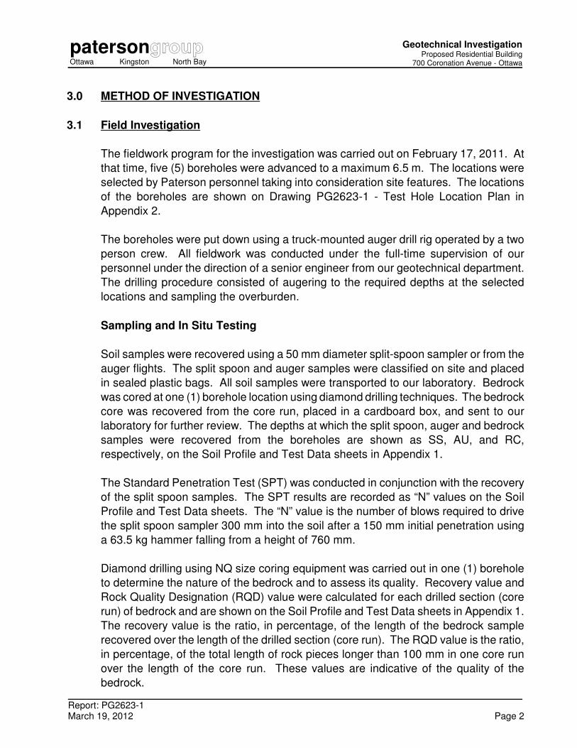
The fieldwork program for the investigation was carried out on February 17, 2011. At
that time, five (5) boreholes were advanced to a maximum 6.5 m. The locations were
selected by Paterson personnel taking into consideration site features. The locations
of the boreholes are shown on Drawing PG2623-1 - Test Hole Location Plan in
Appendix 2.
The boreholes were put down using a truck-mounted auger drill rig operated by a two
person crew. All fieldwork was conducted under the full-time supervision of our
personnel under the direction of a senior engineer from our geotechnical department.
The drilling procedure consisted of augering to the required depths at the selected
locations and sampling the overburden.
Sampling and In Situ Testing
Soil samples were recovered using a 50 mm diameter split-spoon sampler or from the
auger flights. The split spoon and auger samples were classified on site and placed
in sealed plastic bags. All soil samples were transported to our laboratory. Bedrock
was cored at one (1) borehole location using diamond drilling techniques. The bedrock
core was recovered from the core run, placed in a cardboard box, and sent to our
laboratory for further review. The depths at which the split spoon, auger and bedrock
samples were recovered from the boreholes are shown as SS, AU, and RC,
respectively, on the Soil Profile and Test Data sheets in Appendix 1.
The Standard Penetration Test (SPT) was conducted in conjunction with the recovery
of the split spoon samples. The SPT results are recorded as “N” values on the Soil
Profile and Test Data sheets. The “N” value is the number of blows required to drive
the split spoon sampler 300 mm into the soil after a 150 mm initial penetration using
a 63.5 kg hammer falling from a height of 760 mm.
Diamond drilling using NQ size coring equipment was carried out in one (1) borehole
to determine the nature of the bedrock and to assess its quality. Recovery value and
Rock Quality Designation (RQD) value were calculated for each drilled section (core
run) of bedrock and are shown on the Soil Profile and Test Data sheets in Appendix 1.
The recovery value is the ratio, in percentage, of the length of the bedrock sample
recovered over the length of the drilled section (core run). The RQD value is the ratio,
in percentage, of the total length of rock pieces longer than 100 mm in one core run
over the length of the core run. These values are indicative of the quality of the
bedrock.

patersongroupOttawa Kingston North Bay
Geotechnical InvestigationProposed Residential Building
700 Coronation Avenue - Ottawa
Report: PG2623-1
March 19, 2012 Page 3
Subsurface conditions observed in the boreholes were recorded in detail in the field.
Reference should be made to the Soil Profile and Test Data sheets presented in
Appendix 1 for specific details of the soil profile encountered at the test hole locations.
. Groundwater
Flexible standpipes were installed in the boreholes to permit monitoring of the
groundwater levels subsequent to the completion of the sampling program.
Sample Storage
All samples will be stored in the laboratory for a period of one month after issuance of
this report. They will then be discarded unless we are otherwise directed.
3.2 Field Survey
The borehole locations were selected, determined in the field and surveyed by
Paterson. The ground surface elevation at each borehole location was referenced to
a temporary benchmark (TBM), consisting of the top of the catch basin located at the
northeast corner of the subject site. A geodetic elevation of 74.30 m was provided by
Farley, Smith and Denis Surveying for the TBM. The location and ground surface
elevations at borehole locations are presented on Drawing PG2623-1 - Test Hole
Location Plan in Appendix 2.
3.3 Laboratory Testing
The soil samples recovered from the subject site were examined in our laboratory to
review the results of the field logging.
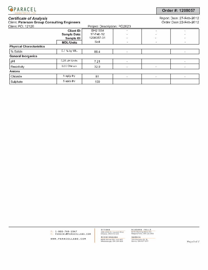
3.4 Analytical Testing
One (1) soil sample was submitted for analytical testing to assess the corrosion
potential for exposed ferrous metals and the potential of sulphate attacks against
subsurface concrete structures. The sample was submitted to determine the
concentration of sulphate and chloride, the resistivity and the pH of the sample. The
results are presented in Appendix 1 and are discussed further in Subsection 6.7.
patersongroupOttawa Kingston North Bay
Geotechnical InvestigationProposed Residential Building
700 Coronation Avenue - Ottawa
Report: PG2623-1
March 19, 2012 Page 4
4.0 OBSERVATIONS
4.1 Surface Conditions
The subject site is currently occupied by a residential apartment building along with
associated parking area to the west of the existing building. A landscaped area was
also noted within the east portion of the site. The site is relatively flat and at grade with
Coronation Avenue and adjacent properties.
4.2 Subsurface Profile
The soil profile encountered at the test hole locations consists of a pavement structure
at ground surface underlain by a fill layer, consisting of a brown silty clay with gravel
and/or silty sand with gravel. A glacial till deposit was noted below the abovenoted
layers followed by a shale bedrock. Shale bedrock was cored at BH 1 to a 6.5 m
depth. Based on the RQD values of the recovered bedrock samples, the bedrock is
of a fair quality. Specific details of the soil profile at the test hole locations are
presented on the Soil Profile and Test Data sheets in Appendix 1.
Based on available geological mapping, the bedrock in the immediate area of the
subject site consists of shale bedrock of the Carlsbad formation.
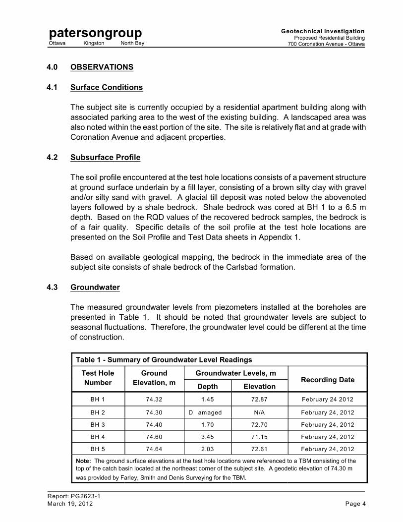
4.3 Groundwater
The measured groundwater levels from piezometers installed at the boreholes are
presented in Table 1. It should be noted that groundwater levels are subject to
seasonal fluctuations. Therefore, the groundwater level could be different at the time
of construction.
Table 1 - Summary of Groundwater Level Readings
Test Hole
Number
Ground
Elevation, m
Groundwater Levels, mRecording Date
Depth Elevation
BH 1 74.32 1.45 72.87 February 24 2012
BH 2 74.30 D amaged N/A February 24, 2012
BH 3 74.40 1.70 72.70 February 24, 2012
BH 4 74.60 3.45 71.15 February 24, 2012
BH 5 74.64 2.03 72.61 February 24, 2012
Note: The ground surface elevations at the test hole locations were referenced to a TBM consisting of the
top of the catch basin located at the northeast corner of the subject site. A geodetic elevation of 74.30 m
was provided by Farley, Smith and Denis Surveying for the TBM.

patersonOttawa Kingston North Bay
Geotechnical InvestigationProposed Residential Building
700 Coronation Avenue - Ottawa
Report: PG2623-1March 19, 2012 Page 5
5.0 DISCUSSION
5.1 Geotechnical Assessment
From a geotechnical perspective, the subject site is considered adequate for the
proposed residential development. It is expected that the proposed building can be
founded by conventional style shallow foundation.
Based on the plans provided, the east foundation wall of the proposed underground
parking structure will be within the lateral support zone of the footings for the existing
building. Consideration should be given to completing an underpinning program for the
existing building to ensure that adequate lateral support is provided. An underpinning
program, such as a 2 to 3 m wide excavation completed with a piano key style
excavation technique and extending to the proposed underside of footing of the parking
structure, would be adequate. The excavation should be in-filled with a lean concrete
to underside of footing level prior to excavating adjacent sections.
The above and other considerations are discussed in the following paragraphs.
5.2 Site Grading and Preparation
Stripping Depth
Asphalt, topsoil or fill, containing deleterious and organic materials, should be stripped
from under any buildings, paved areas, pipe bedding and other settlement sensitive
structures.
Existing foundation walls and other construction debris should be entirely removed from
within the proposed building perimeter. Under paved areas, existing construction
remnants such as foundation walls should be removed to a minimum of 1 m below final
grade.
Bedrock Removal
Bedrock removal can be accomplished by hoe ramming where only a small quantity of
the bedrock needs to be removed. Sound bedrock may be removed by line drilling and
controlled blasting and/or hoe ramming.

patersonOttawa Kingston North Bay
Geotechnical InvestigationProposed Residential Building
700 Coronation Avenue - Ottawa
Report: PG2623-1March 19, 2012 Page 6
Prior to considering blasting operations, the blasting effects on the existing services,
buildings and other structures should be addressed. A pre-blast or pre-construction
survey of the existing structures located in proximity of the blasting operations should
be carried out prior to commencing site activities. The extent of the survey should be
determined by the blasting consultant and should be sufficient to respond to any
inquiries/claims related to the blasting operations.
As a general guideline, peak particle velocities (measured at the structures) should not
exceed 25 mm per second during the blasting program to reduce the risks of damage
to the existing structures.
The blasting operations should be planned and conducted under the supervision of a
licensed professional engineer who is also an experienced blasting consultant.
Excavation side slopes in sound bedrock can be carried out using almost vertical side
walls. A minimum 1 m horizontal ledge, should be left between the bottom of the
overburden excavation and the top of the bedrock surface to provide an area to allow
for potential sloughing.
Fill Placement
Fill used for grading beneath the building areas should consist, unless otherwise
specified, of clean imported granular fill, such as Ontario Provincial Standard
Specifications (OPSS) Granular A or Granular B Type II. This material should be
tested and approved prior to delivery to the site. The fill should be placed in lifts no
greater than 300 mm thick and compacted using suitable compaction equipment for the
lift thickness. Fill placed beneath the proposed building should be compacted to at
least 98% of its standard Proctor maximum dry density (SPMDD).
Non-specified existing fill along with site-excavated soil can be used as general
landscaping fill where settlement of the ground surface is of minor concern. These
materials should be spread in thin lifts and at least compacted by the tracks of the
spreading equipment to minimize voids. If these materials are to be used to build up
the subgrade level for areas to be paved, they should be compacted in thin lifts to a
minimum density of 95% of their respective SPMDD. Non-specified existing fill and
site-excavated soils are not suitable for use as backfill against foundation walls unless
a composite drainage blanket connected to a perimeter drainage system is provided.
patersonOttawa Kingston North Bay
Geotechnical InvestigationProposed Residential Building
700 Coronation Avenue - Ottawa
Report: PG2623-1March 19, 2012 Page 7
5.3 Foundation Design
Footings placed on an undisturbed, dense glacial till bearing surface can be designed
using a bearing resistance value at serviceability limit states (SLS) of 150 kPa and a
factored bearing resistance value at ultimate limit states (ULS) of 225 kPa. A
geotechnical resistance factor of 0.5 was applied to the reported bearing resistance
value at ULS. The bearing resistance value at SLS will be subjected to potential post-
construction total and differential settlements of 25 and 20 mm, respectively.
An undisturbed soil bearing surface consists of a surface from which all topsoil and
deleterious materials, such as loose, frozen or disturbed soil, whether in situ or not,
have been removed, in the dry, prior to the placement of concrete for footings.
The bearing medium under footing-supported structures is required to be provided with
adequate lateral support with respect to excavations and different foundation levels.
Adequate lateral support is provided to a glacial till or engineered fill bearing medium
when a plane extending down and out from the bottom edge of the footing at a
minimum of 1.5H:1V, passes only through in situ soil or engineered fill of the same or
higher capacity as the soil.
Footings placed on a clean, surface-sounded bedrock surface can be designed using
a bearing resistance value at SLS of 500 kPa and a factored bearing resistance value
at ULS of 750 kPa.
A clean, surface-sounded bedrock bearing surface should be free of all soil and loose
materials, and have no near surface seams, voids, fissures or open joints which can
be detected from surface sounding with a rock hammer.
The bearing medium under footing-supported structures is required to be provided with
adequate lateral support. Near vertical (1H:6V) slopes can be used for unfractured
bedrock bearing media. A 1H:1V slope can be used for fractured/weathered bedrock.
The potential long term post-construction total and differential settlements for footings
placed on surface-sounded bedrock are estimated to be negligible.

patersongroupOttawa Kingston North Bay
Geotechnical InvestigationProposed Residential Building
700 Coronation Avenue - Ottawa
Report: PG2623-1
March 19, 2012 Page 8
5.4 Design for Earthquakes
The site class for seismic site response can be taken as Class C for the foundations
considered at this site. The soils underlying the proposed shallow foundations are not
susceptible to liquefaction. A higher site class, such as a Class B, may be applicable
for design of the proposed building. However, the higher site class has to be confirmed
by site specific shear wave velocity testing. Reference should be made to the latest
revision of the 2006 Ontario Building Code for a full discussion of the earthquake
design requirements.
5.5 Basement Slab
With the removal of all topsoil, and deleterious fill, containing organic matter, within the
footprint of the proposed building, the native soil surface will be considered to be an
acceptable subgrade surface on which to commence backfilling for floor slab
construction. Any soft areas should be removed and backfilled with appropriate backfill
material. OPSS Granular B Type II is recommended for backfilling below the floor slab.
It is recommended that the upper 200 mm of sub-slab fill consist of 19 mm clear
crushed stone.
It is understood that an underground parking level is anticipated for the proposed
building. It is expected that a concrete slab topping with a sub-floor granular layer will
be incorporated in the design to accommodate services and the rigid pavement
structure noted in Subsection 5.7 will be applicable.
5.6 Basement Wall
There are several combinations of backfill materials and retained soils that could be
applicable for the basement walls of the subject structure. However, the conditions can
be well-represented by assuming the retained soil consists of a material with an angle
of internal friction of 30 degrees and a bulk (drained) unit weight of 20 kN/m . 3
However, undrained conditions are anticipated (i.e. below the groundwater level).
Therefore, the applicable effective (undrained) unit weight of the retained soil can be
taken as 13 kN/m , where applicable. A hydrostatic pressure should be added to the3
total static earth pressure when using the effective unit weight. The total earth
AE opressure (P ) includes both the static earth pressure component (P ) and the seismic
AEcomponent (ÄP ).
patersongroupOttawa Kingston North Bay
Geotechnical InvestigationProposed Residential Building
700 Coronation Avenue - Ottawa
Report: PG2623-1
March 19, 2012 Page 9
Lateral Earth Pressures
oThe static horizontal earth pressure (p ) can be calculated using a triangular earth
opressure distribution equal to K ·ã·H where:
oK = at-rest earth pressure coefficient of the applicable retained soil, 0.5
ã = unit weight of fill of the applicable retained soil (kN/m )3
H = height of the wall (m)
oAn additional pressure having a magnitude equal to K ·q and acting on the entire height
of the wall should be added to the above diagram for any surcharge loading, q (kPa),
that may be placed at ground surface adjacent to the wall. Note that surcharge
pressure will only be applicable for static analyses and should not be used in
conjunction with the seismic loading case.
Actual earth pressures could be higher than the “at-rest” case if care is not exercised
during the compaction of the backfill materials to stay at least 0.3 m away from the
walls with the compaction equipment.
Seismic Earth Pressures
AEThe seismic earth pressure (ÄP ) can be calculated using the earth pressure
cdistribution equal to 0.375·a ·ã·H /g where: 2
c max maxa = (1.45-a /g)a
ã = unit weight of applicable retained soil (kN/m )3
H = height of the wall (m)
g = gravity, 9.81 m/s2
maxThe peak ground acceleration, (a ), for the Ottawa area is 0.42g according to
OBC 2006. Note that the vertical seismic coefficient is assumed to be zero.
oThe earth force component (P ) under seismic conditions can be calculated using
o o oP = 0.5 K ã H , where K = 0.5 for the soil conditions noted above. 2
AEThe total earth pressure (P ) is considered to act at a height, h (m), from the base of
the wall, where:
o AE AEh = {P ·(H/3)+ÄP ·(0.6·H)}/P

patersonOttawa Kingston North Bay
Geotechnical InvestigationProposed Residential Building
700 Coronation Avenue - Ottawa
Report: PG2623-1March 19, 2012 Page 10
The earth pressures calculated are unfactored. For the ULS case, the earth pressure
loads should be factored as live loads, as per OBC 2006.
5.7 Pavement Structure
The proposed parking level slab will be considered a rigid pavement structure. The
following rigid pavement structure is suggested to support car parking only.
Table 2 - Recommended Rigid Pavement Structure - Car Only Parking Areas
Thickness
(mm)Material Description
125 Wear Course - Concrete slab
150 BASE - 20 mm clear stone
SUBGRADE - Either in situ soils, engineered fill or OPSS Granular B Type I or II material placed over
in situ soil.
The recommended flexible pavement structures shown in Tables 3 and 4 would be
applicable, where a flexible asphaltic concrete is required.
Table 3 - Recommended Pavement Structure - Car Only Parking Areas
Thickness
(mm)Material Description
50 Wear Course - HL-3 or Superpave 12.5 Asphaltic Concrete
150 BASE - OPSS Granular A Crushed Stone
300 SUBBASE - OPSS Granular B Type II
SUBGRADE - Either in situ soils, engineered fill or OPSS Granular B Type I or II material placed
over in situ soil
patersonOttawa Kingston North Bay
Geotechnical InvestigationProposed Residential Building
700 Coronation Avenue - Ottawa
Report: PG2623-1March 19, 2012 Page 11
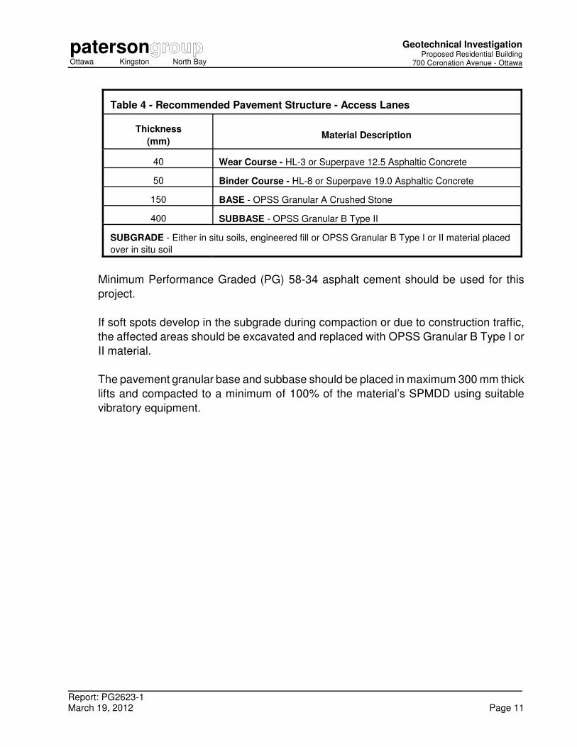
Table 4 - Recommended Pavement Structure - Access Lanes
Thickness
(mm)Material Description
40 Wear Course - HL-3 or Superpave 12.5 Asphaltic Concrete
50 Binder Course - HL-8 or Superpave 19.0 Asphaltic Concrete
150 BASE - OPSS Granular A Crushed Stone
400 SUBBASE - OPSS Granular B Type II
SUBGRADE - Either in situ soils, engineered fill or OPSS Granular B Type I or II material placed
over in situ soil
Minimum Performance Graded (PG) 58-34 asphalt cement should be used for this
project.
If soft spots develop in the subgrade during compaction or due to construction traffic,
the affected areas should be excavated and replaced with OPSS Granular B Type I or
II material.
The pavement granular base and subbase should be placed in maximum 300 mm thick
lifts and compacted to a minimum of 100% of the material’s SPMDD using suitable
vibratory equipment.
patersonOttawa Kingston North Bay
Geotechnical InvestigationProposed Residential Building
700 Coronation Avenue - Ottawa
Report: PG2623-1March 19, 2012 Page 12
6.0 DESIGN AND CONSTRUCTION PRECAUTIONS
6.1 Foundation Drainage and Backfill
It is recommended that a perimeter foundation drainage system be provided for the
proposed building. The system should consist of a 100 to 150 mm diameter perforated
corrugated plastic pipe, surrounded on all sides by 150 mm of 10 mm clear crushed
stone, placed at the footing level around the exterior perimeter of the structure. The
pipe should have a positive outlet, such as a gravity connection to the storm sewer.
Backfill against the exterior sides of the foundation walls should consist of free-draining
non frost susceptible granular materials. The greater part of the site excavated
materials will be frost susceptible and, as such, are not recommended for re-use as
backfill against the foundation walls, unless used in conjunction with a drainage
geocomposite, such as Miradrain G100N or Delta Drain 6000, connected to the
perimeter foundation drainage system. Imported granular materials, such as clean
sand or OPSS Granular B Type I granular material, should otherwise be used for this
purpose.
6.2 Protection of Footings Against Frost Action
Perimeter footings of heated structures are required to be insulated against the
deleterious effect of frost action. A minimum of 1.5 m thick soil cover (or equivalent)
should be provided in this regard.
A minimum of 2.1 m thick soil cover (or equivalent) should be provided for exterior
unheated footings, not thermally connected to a heated space, such as exterior
columns and/or wing walls.
6.3 Excavation Side Slopes
The side slopes of excavations in the soil and fill overburden materials should either be
cut back at acceptable slopes or should be retained by shoring systems from the start
of the excavation until the structure is backfilled. It is assumed that sufficient room will
be available for the greater part of the excavation to be undertaken by open-cut
methods (i.e. unsupported excavations).
patersonOttawa Kingston North Bay
Geotechnical InvestigationProposed Residential Building
700 Coronation Avenue - Ottawa
Report: PG2623-1March 19, 2012 Page 13
The excavation side slopes above the groundwater level extending to a maximum depth
of 3 m should be cut back at 1H:1V or flatter. The flatter slope is required for
excavation below the groundwater level. The subsoil at this site is considered to be
mainly a Type 2 and 3 soil according to the Occupational Health and Safety Act and
Regulations for Construction Projects.
Excavated soil should not be stockpiled directly at the top of excavations and heavy
equipment should be kept away from the excavation sides.
Slopes in excess of 3 m in height should be periodically inspected by the geotechnical
consultant in order to detect if the slopes are exhibiting signs of distress.
It is recommended that a trench box be used at all times to protect personnel working
in trenches with steep or vertical sides. It is expected that services will be installed by
“cut and cover” methods and excavations will not be left open for extended periods of
time.
6.4 Pipe Bedding and Backfill
At least 150 mm of OPSS Granular A should be used for pipe bedding for sewer and
water pipes. The bedding should extend to the spring line of the pipe. Cover material,
from the spring line to at least 300 mm above the obvert of the pipe, should consist of
OPSS Granular A. The bedding and cover materials should be placed in maximum
225 mm thick lifts compacted to a minimum of 95% of the material’s SPMDD.
Where hard surface areas are considered above the trench backfill, the trench backfill
material within the frost zone (about 1.8 m below finished grade) should match the soils
exposed at the trench walls to minimize differential frost heaving. The trench backfill
should be placed in maximum 300 mm thick loose lifts and compacted to a minimum
of 95% of the material’s SPMDD.
6.5 Groundwater Control
The contractor should be prepared to direct water away from all bearing surfaces and
subgrades, regardless of the source, to prevent disturbance to the founding medium.
It is anticipated that pumping from open sumps will be sufficient to control the
groundwater influx through the sides of the excavations.
patersonOttawa Kingston North Bay
Geotechnical InvestigationProposed Residential Building
700 Coronation Avenue - Ottawa
Report: PG2623-1March 19, 2012 Page 14
A temporary MOE permit to take water (PTTW) will be required for this project if more
than 50,000 L/day are to be pumped during the construction phase. At least 3 to
4 months should be allowed for completion of the application and issuance of the permit
by the MOE.
6.6 Winter Construction
Precautions must be taken if winter construction is considered for this project. The
subsoil conditions at this site consist of frost susceptible materials. In the presence of
water and freezing conditions, ice could form within the soil mass. Heaving and
settlement upon thawing could occur.
In the event of construction during below zero temperatures, the founding stratum
should be protected from freezing temperatures by the use of straw, propane heaters
and tarpaulins or other suitable means. In this regard, the base of the excavations
should be insulated from sub-zero temperatures immediately upon exposure and until
such time as heat is adequately supplied to the building and the footings are protected
with sufficient soil cover to prevent freezing at founding level.
Trench excavations and pavement construction are also difficult activities to complete
during freezing conditions without introducing frost in the subgrade or in the excavation
walls and bottoms. Precautions should be taken if such activities are to be carried out
during freezing conditions.
6.7 Corrosion Potential and Sulphate
The results of analytical testing show that the sulphate content is less than 0.1%. This
result is indicative that Type 10 Portland cement (normal cement) would be appropriate
for this site. The chloride content and the pH of the sample indicate that they are not
significant factors in creating a corrosive environment for exposed ferrous metals at this
site, whereas the resistivity is indicative of an aggressive corrosive environment.
patersonOttawa Kingston North Bay
Geotechnical InvestigationProposed Residential Building
700 Coronation Avenue - Ottawa
Report: PG2623-1March 19, 2012 Page 15
7.0 RECOMMENDATIONS
It is a requirement for the foundation design data provided herein to be applicable that
a materials testing and observation services program including the following aspects be
performed by the geotechnical consultant.
‘ Observation of all bearing surfaces prior to the placement of concrete.
‘ Sampling and testing of the concrete and granular fill materials used.
‘ Periodic observation of the condition of unsupported excavation side slopes in
excess of 3 m in height, if applicable.
‘ Observation of all subgrades prior to backfilling.
‘ Field density tests to determine the level of compaction achieved.
‘ Sampling and testing of the bituminous concrete including mix design reviews.
A report confirming that these works have been conducted in general accordance with
our recommendations could be issued, upon request, following the completion of a
satisfactory materials testing and observation program by the geotechnical consultant.
patersongroupOttawa Kingston North Bay
Geotechnical InvestigationProposed Residential Building
700 Coronation Avenue - Ottawa
Report: PG2623-1
March 19, 2012 Page 16
8.0 STATEMENT OF LIMITATIONS
The recommendations provided in this report are in accordance with our present
understanding of the project. We request permission to review our recommendations
when the drawings and specifications are completed.
A soils investigation is a limited sampling of a site. Should any conditions at the site
be encountered which differ from those at the test locations, we request immediate
notification to permit reassessment of our recommendations.
The present report applies only to the project described in this document. Use of this
report for purposes other than those described herein or by person(s) other than
MJ Asset Management or their agents is not authorized without review by Paterson for
the applicability of our recommendations to the alternative use of the report.
Paterson Group Inc.
Kirk Thompson, B.Eng. David J. Gilbert, P.Eng.
Report Distribution:
� M J Asset Management (3 copies)
� Paterson Group (1 copy)

APPENDIX 1
SOIL PROFILE AND TEST DATA SHEETS
SYMBOLS AND TERMS
ANALYTICAL TEST RESULTS
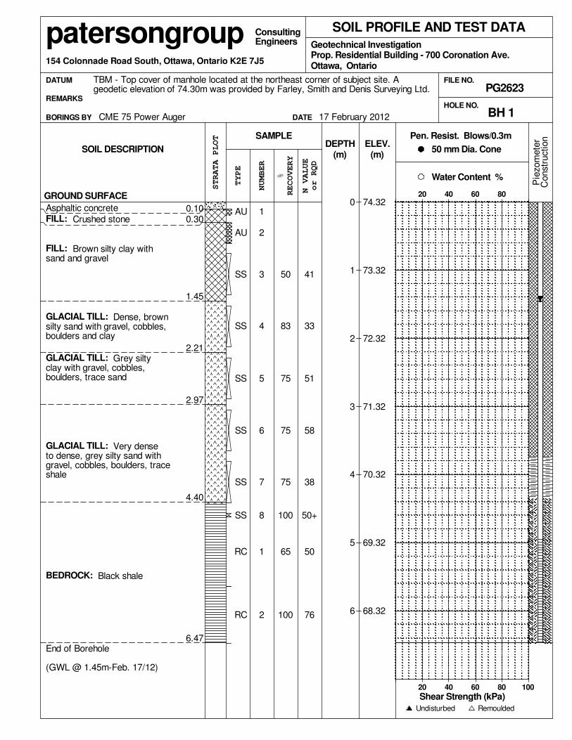
RC
FILL: Brown silty clay withsand and gravel
FILL: Crushed stone
Asphaltic concrete
6.47
4.40
2.97
2.21
1.45
0.10
GLACIAL TILL: Very denseto dense, grey silty sand withgravel, cobbles, boulders, traceshale
RC
SS
SS
SS
SS
SS
SS
AU
AU0.30
GROUND SURFACE
SOIL DESCRIPTION
Shear Strength (kPa)
FILE NO.
RECOVERY
N VALUE
20 40 60 80 100
GLACIAL TILL: Dense, brownsilty sand with gravel, cobbles,boulders and clay
GLACIAL TILL: Grey siltyclay with gravel, cobbles,boulders, trace sand
End of Borehole
(GWL @ 1.45m-Feb. 17/12)
BEDROCK: Black shale
8
2
33
51
757
6
5
4
3
2
1
100
41
100
1
75
75
83
50
76
50
50+
38
58
65
TBM - Top cover of manhole located at the northeast corner of subject site. Ageodetic elevation of 74.30m was provided by Farley, Smith and Denis Surveying Ltd.
20 40 60 80
Engineers
(m)
74.32
73.32
72.32
71.32
70.32
69.32
68.32
(m)
CME 75 Power Auger
SOIL PROFILE AND TEST DATA
REMARKS
BORINGS BY
DATUM
Remoulded
Pie
zom
ete
r
DATE
Geotechnical Investigation
PG2623
Water Content %
patersongroup154 Colonnade Road South, Ottawa, Ontario K2E 7J5
50 mm Dia. Cone
Consulting
SAMPLE
%
Pen. Resist. Blows/0.3m
0
1
2
3
4
5
6
HOLE NO.
Prop. Residential Building - 700 Coronation Ave.
STRATA PLOT
TYPE
17 February 2012
or RQD
Constr
uction
DEPTH
Undisturbed
Ottawa, Ontario
NUMBER
ELEV.
BH 1
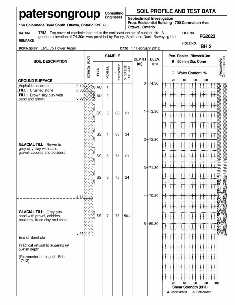
GLACIAL TILL: Brown togrey silty clay with sand,gravel, cobbles and boulders
GLACIAL TILL: Grey siltysand with gravel, cobbles,boulders, trace clay and shale
RECOVERY
FILL: Brown silty clay withsand and gravel
FILL: Crushed stone
Asphaltic concrete
5.41
4.11
0.60
0.30
End of Borehole
Practical refusal to augering @5.41m depth
(Piezometer damaged - Feb.17/12)
HOLE NO.
STRATA PLOT
%
TYPE
20 40 60 80 100
GROUND SURFACE
N VALUE
74.30
73.30
72.30
71.30
70.30
69.30
SOIL DESCRIPTION
Shear Strength (kPa)
FILE NO.
SS
0.10
34
21
24
50+
4
Prop. Residential Building - 700 Coronation Ave.
SS
SS
SS
AU
AU
7
215
SS
3
2
1
75
75
75
83
83
6
SOIL PROFILE AND TEST DATA
(m)
PG2623
20 40 60 80
Engineers
(m)
CME 75 Power Auger
TBM - Top cover of manhole located at the northeast corner of subject site. Ageodetic elevation of 74.30m was provided by Farley, Smith and Denis Surveying Ltd.
REMARKS
BORINGS BY
Pen. Resist. Blows/0.3m
Pie
zom
ete
r
DATE
Geotechnical Investigation
50 mm Dia. Cone
Water Content %
Remoulded
patersongroup154 Colonnade Road South, Ottawa, Ontario K2E 7J5
Consulting
SAMPLE
Ottawa, Ontario
ELEV.
0
1
2
3
4
5
DEPTH
DATUM
17 February 2012 BH 2
NUMBER
Undisturbed
or RQD
Constr
uction

20 40 60 80 100
RECOVERY
End of Borehole
Practical refusal to augering @3.28m depth
(GWL @ 1.70m-Feb. 17/12)
GLACIAL TILL: Grey siltysand with gravel, cobbles,boulders, trace clay
GLACIAL TILL: Brown siltyclay with sand, gravel, cobblesand boulders
FILL: Crushed stone withgravel and sand
FILL: Crushed stone
Asphaltic concrete
Prop. Residential Building - 700 Coronation Ave.
STRATA PLOT
%
TYPE
GROUND SURFACE
N VALUE
0.60
HOLE NO.
Pen. Resist. Blows/0.3m
74.40
73.40
72.40
71.40
SOIL DESCRIPTION
Shear Strength (kPa)
FILE NO.
27
35
19
3.28
100
6
0.300.10
SS
SS
SS
SS
50+
AU
83
5
4
3
2
1
60
83
2.21
AU
SOIL PROFILE AND TEST DATA
(m)
PG2623
20 40 60 80
Engineers
(m)
CME 75 Power Auger
TBM - Top cover of manhole located at the northeast corner of subject site. Ageodetic elevation of 74.30m was provided by Farley, Smith and Denis Surveying Ltd.
REMARKS
BORINGS BY
Pie
zom
ete
r
DATE
Geotechnical Investigation
50 mm Dia. Cone
Water Content %
Remoulded
patersongroup154 Colonnade Road South, Ottawa, Ontario K2E 7J5
Consulting
ELEV.
Ottawa, Ontario
BH 3
SAMPLEDEPTH
0
1
2
3
17 February 2012
NUMBER
DATUM
Constr
uction
or RQD
Undisturbed
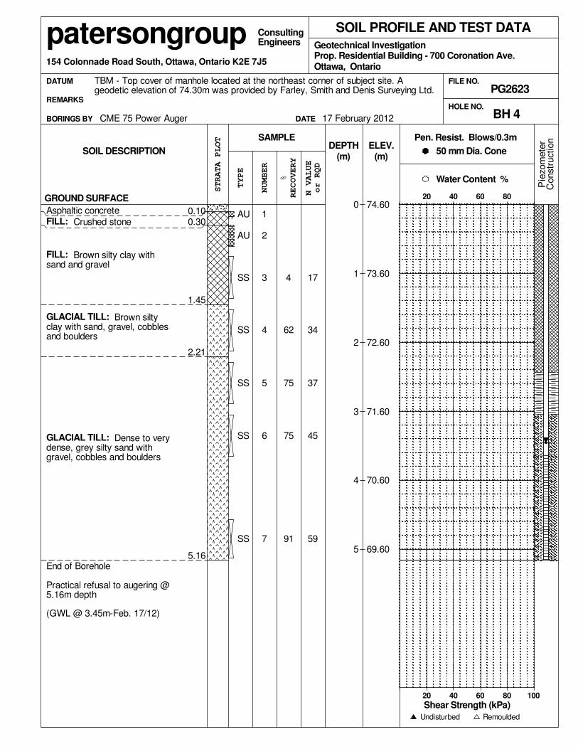
GLACIAL TILL: Dense to verydense, grey silty sand withgravel, cobbles and boulders
0.10
End of Borehole
Practical refusal to augering @5.16m depth
(GWL @ 3.45m-Feb. 17/12)
20 40 60 80 100
GLACIAL TILL: Brown siltyclay with sand, gravel, cobblesand boulders
FILL: Brown silty clay withsand and gravel
FILL: Crushed stone
Asphaltic concrete
5.16
2.21
1.45
STRATA PLOT Pen. Resist. Blows/0.3m
%
TYPE
GROUND SURFACE
SS
SOIL DESCRIPTION
Shear Strength (kPa)
FILE NO.
RECOVERY
N VALUE
Prop. Residential Building - 700 Coronation Ave.
0.30
34
17
45
59
4
SS
SS
SS
SS
AU
AU
7
375
HOLE NO.
3
2
1
91
75
75
62
4
6
SOIL PROFILE AND TEST DATA
(m)
PG2623
20 40 60 80
Engineers
(m)50 mm Dia. Cone
CME 75 Power Auger
TBM - Top cover of manhole located at the northeast corner of subject site. Ageodetic elevation of 74.30m was provided by Farley, Smith and Denis Surveying Ltd.
REMARKS
BORINGS BY
74.60
73.60
72.60
71.60
70.60
69.60P
iezom
ete
r
DATE
Geotechnical Investigation
Consulting
Water Content %
Remoulded
patersongroup154 Colonnade Road South, Ottawa, Ontario K2E 7J5
DEPTH
Ottawa, Ontario
ELEV.
0
1
2
3
4
5
SAMPLE
DATUM
17 February 2012 BH 4
NUMBER
Undisturbed
or RQD
Constr
uction

GLACIAL TILL: Dense to verydense, grey silty sand withgravel, cobbles, boulders, traceclay
0.10
End of Borehole
Practical refusal to augering @5.41m depth.
(GWL @ 2.03m-Feb. 17/12)
20 40 60 80 100
GLACIAL TILL: Brown siltyclay with sand, gravel, cobblesand boulders
FILL: Brown silty sand withgravel, trace clay
FILL: Crushed stone
Asphaltic concrete
5.41
2.21
0.69
STRATA PLOT Pen. Resist. Blows/0.3m
%
TYPE
GROUND SURFACE
SS
SOIL DESCRIPTION
Shear Strength (kPa)
FILE NO.
RECOVERY
N VALUE
Prop. Residential Building - 700 Coronation Ave.
0.30
34
26
35
80
4
SS
SS
SS
SS
AU
AU
7
305
HOLE NO.
3
2
1
100
83
83
100
37
6
SOIL PROFILE AND TEST DATA
(m)
PG2623
20 40 60 80
Engineers
(m)50 mm Dia. Cone
CME 75 Power Auger
TBM - Top cover of manhole located at the northeast corner of subject site. Ageodetic elevation of 74.30m was provided by Farley, Smith and Denis Surveying Ltd.
REMARKS
BORINGS BY
74.64
73.64
72.64
71.64
70.64
69.64P
iezom
ete
r
DATE
Geotechnical Investigation
Consulting
Water Content %
Remoulded
patersongroup154 Colonnade Road South, Ottawa, Ontario K2E 7J5
DEPTH
Ottawa, Ontario
ELEV.
0
1
2
3
4
5
SAMPLE
DATUM
17 February 2012 BH 5
NUMBER
Undisturbed
or RQD
Constr
uction

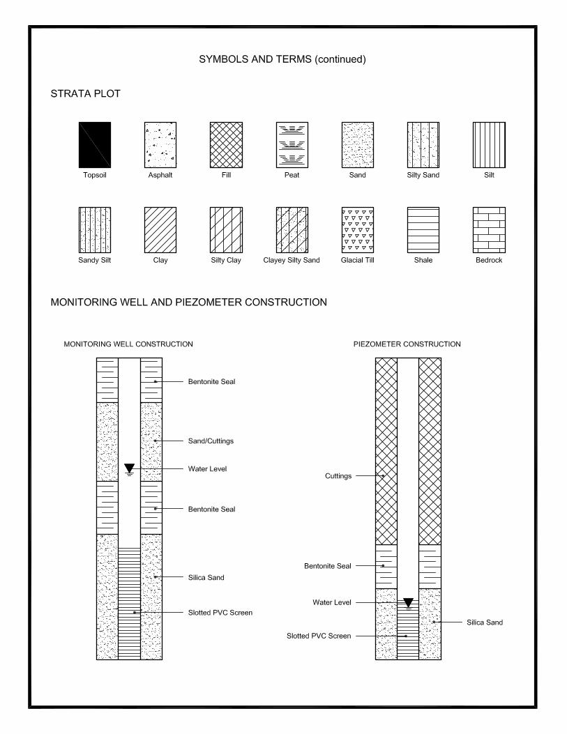
SYMBOLS AND TERMS
SOIL DESCRIPTION Behavioural properties, such as structure and strength, take precedence over particle gradation in
describing soils. Terminology describing soil structure are as follows:
Desiccated - having visible signs of weathering by oxidation of clay
minerals, shrinkage cracks, etc.
Fissured - having cracks, and hence a blocky structure.
Varved - composed of regular alternating layers of silt and clay.
Stratified - composed of alternating layers of different soil types, e.g. silt
and sand or silt and clay.
Well-Graded - Having wide range in grain sizes and substantial amounts of
all intermediate particle sizes (see Grain Size Distribution).
Uniformly-Graded - Predominantly of one grain size (see Grain Size Distribution).
The standard terminology to describe the strength of cohesionless soils is the relative density, usually
inferred from the results of the Standard Penetration Test (SPT) ‘N’ value. The SPT N value is the
number of blows of a 63.5 kg hammer, falling 760 mm, required to drive a 51 mm O.D. split spoon
sampler 300 mm into the soil after an initial penetration of 150 mm.
Relative Density ‘N’ Value Relative Density %
Very Loose <4 <15
Loose 4-10 15-35
Compact 10-30 35-65
Dense 30-50 65-85
Very Dense >50 >85
The standard terminology to describe the strength of cohesive soils is the consistency, which is based on
the undisturbed undrained shear strength as measured by the in situ or laboratory vane tests,
penetrometer tests, unconfined compression tests, or occasionally by Standard Penetration Tests.
Consistency Undrained Shear Strength (kPa) ‘N’ Value
Very Soft <12 <2
Soft 12-25 2-4
Firm 25-50 4-8
Stiff
Very Stiff
50-100
100-200
8-15
15-30
Hard >200 >30

SYMBOLS AND TERMS (continued)
SOIL DESCRIPTION (continued) Cohesive soils can also be classified according to their “sensitivity”. The sensitivity is the ratio between
the undisturbed undrained shear strength and the remoulded undrained shear strength of the soil.
Terminology used for describing soil strata based upon texture, or the proportion of individual particle
sizes present is provided on the Textural Soil Classification Chart at the end of this information package.
ROCK DESCRIPTION The structural description of the bedrock mass is based on the Rock Quality Designation (RQD).
The RQD classification is based on a modified core recovery percentage in which all pieces of sound core
over 100 mm long are counted as recovery. The smaller pieces are considered to be a result of closely-
spaced discontinuities (resulting from shearing, jointing, faulting, or weathering) in the rock mass and are
not counted. RQD is ideally determined from NXL size core. However, it can be used on smaller core
sizes, such as BX, if the bulk of the fractures caused by drilling stresses (called “mechanical breaks”) are
easily distinguishable from the normal in situ fractures.
RQD % ROCK QUALITY
90-100 Excellent, intact, very sound
75-90 Good, massive, moderately jointed or sound
50-75 Fair, blocky and seamy, fractured
25-50 Poor, shattered and very seamy or blocky, severely fractured
0-25 Very poor, crushed, very severely fractured
SAMPLE TYPES
SS - Split spoon sample (obtained in conjunction with the performing of the Standard
Penetration Test (SPT))
TW - Thin wall tube or Shelby tube
PS - Piston sample
AU - Auger sample or bulk sample
WS - Wash sample
RC - Rock core sample (Core bit size AXT, BXL, etc.). Rock core samples are
obtained with the use of standard diamond drilling bits.
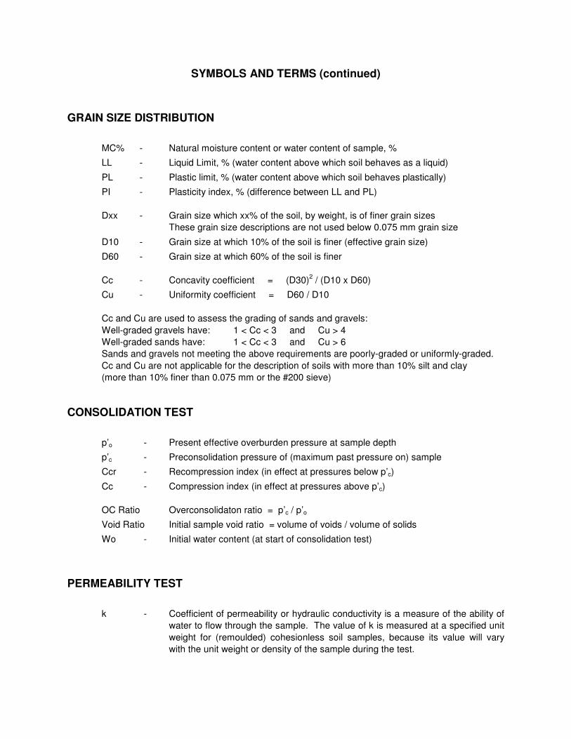
SYMBOLS AND TERMS (continued)
GRAIN SIZE DISTRIBUTION
MC% - Natural moisture content or water content of sample, %
LL - Liquid Limit, % (water content above which soil behaves as a liquid)
PL - Plastic limit, % (water content above which soil behaves plastically)
PI - Plasticity index, % (difference between LL and PL)
Dxx - Grain size which xx% of the soil, by weight, is of finer grain sizes
These grain size descriptions are not used below 0.075 mm grain size
D10 - Grain size at which 10% of the soil is finer (effective grain size)
D60 - Grain size at which 60% of the soil is finer
Cc - Concavity coefficient = (D30)2 / (D10 x D60)
Cu - Uniformity coefficient = D60 / D10
Cc and Cu are used to assess the grading of sands and gravels:
Well-graded gravels have: 1 < Cc < 3 and Cu > 4
Well-graded sands have: 1 < Cc < 3 and Cu > 6
Sands and gravels not meeting the above requirements are poorly-graded or uniformly-graded.
Cc and Cu are not applicable for the description of soils with more than 10% silt and clay
(more than 10% finer than 0.075 mm or the #200 sieve)
CONSOLIDATION TEST
p’o - Present effective overburden pressure at sample depth
p’c - Preconsolidation pressure of (maximum past pressure on) sample
Ccr - Recompression index (in effect at pressures below p’c)
Cc - Compression index (in effect at pressures above p’c)
OC Ratio Overconsolidaton ratio = p’c / p’o
Void Ratio Initial sample void ratio = volume of voids / volume of solids
Wo - Initial water content (at start of consolidation test)
PERMEABILITY TEST
k - Coefficient of permeability or hydraulic conductivity is a measure of the ability of
water to flow through the sample. The value of k is measured at a specified unit
weight for (remoulded) cohesionless soil samples, because its value will vary
with the unit weight or density of the sample during the test.
� � � � � � � � � � � � � � � � � � � � � � � � � � � � � � � � � � � � � � � � � � � ! �" � # � � � � � � �� � � � � � � � ! �� � � � � � $ " � ! � ! � $ � � % � & � � � ' & � � � � � � � � $ ( � ) � *+ , - . / 0 1 2 3 / 1 4 5 6 1 2 0 4 7 - 8 2 9 : 2 9 8 2 . . / 0 ; < = > < ? @ A B C D C E FG H I J K L M N O P Q R S S T U U UV W X Y H J N W L J O UUUZ [ U \ ] ^ U Z RZ R _ ` _ a [ U _ Z U U UV W X Y H J M N Ob N c d e K I L f S g h i U U Uj k l f I m W H G k W n W m L J n I f L I m fo S g i h p q UUU` ` r Ts t u v w x y z t{ J K J n W H M K | n } W K I m f~ Q UUU[ r R Zs t s � � � � � � z �� ] q h q � h � h � � UUU� R r �s t u s � � � t �� K I | K f� � i g � h p ] UUU` Z� � � � � � � xS � i ~ � � � ] UUUZ _ _� � � � � � � x� � � � � � ¡

APPENDIX 2
FIGURE 1 - KEY PLAN
DRAWING PG2623-1 - TEST HOLE LOCATION PLAN
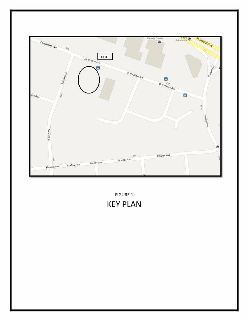
FIGURE 1
KEY PLAN
