photo flash and camera timer controller - high speed photography
TRANSCRIPT

UNIVERSAL PHOTO TIMERUNIVERSAL PHOTO TIMERUNIVERSAL PHOTO TIMERUNIVERSAL PHOTO TIMER TM
PHOTO FLASH AND CAMERA TIMER CONTROLLER
USER GUIDE
Rev A2.

1
2
TABLE OF CONTENTSTABLE OF CONTENTSTABLE OF CONTENTSTABLE OF CONTENTS
1. WARNINGS............................................................................................................................ 3
2. INTRODUCTION .................................................................................................................. 4
3. TIMER CONTROLS AND CONNECTIONS ...................................................................... 5
4. QUICK START GUIDE ......................................................................................................... 6
5. DESCRIPTION OF MENUS................................................................................................ 15
6. SPECIFICATIONS ............................................................................................................... 34
7. SAMPLE PROJECTS............................................................................................................ 37
8. CONNECTION DIAGRAMS .............................................................................................. 41
9. TERMS AND CONDITIONS.............................................................................................. 48
10. RETURN AND WARRANTY .......................................................................................... 48
3
1. WARNINGS
To prevent damage to the product or injury to yourself or to others, read the following safety
precautions in their entirety before using this equipment.
KEEP OUT OF REACH OF CHILDRENKEEP OUT OF REACH OF CHILDRENKEEP OUT OF REACH OF CHILDRENKEEP OUT OF REACH OF CHILDREN
Failure to observe this precaution could result in injury.
TURN OFF IMMEDIATELY IN THE EVENT OF TURN OFF IMMEDIATELY IN THE EVENT OF TURN OFF IMMEDIATELY IN THE EVENT OF TURN OFF IMMEDIATELY IN THE EVENT OF
MALFUNCTION.MALFUNCTION.MALFUNCTION.MALFUNCTION.
Should you notice smoke or an unusual smell coming
from the equipment remove the battery immediately,
taking care to avoid burns. Continued operation could
result in injury.
DO NOTDO NOTDO NOTDO NOT USE IN THE PRESENCE OF FLAMMABLE USE IN THE PRESENCE OF FLAMMABLE USE IN THE PRESENCE OF FLAMMABLE USE IN THE PRESENCE OF FLAMMABLE
GASGASGASGAS
Do not use electronic equipment in the presence of
flammable gas, as this could result in explosion or fire.
OBSERVE PROPER PRECAUTIONS WHEN OBSERVE PROPER PRECAUTIONS WHEN OBSERVE PROPER PRECAUTIONS WHEN OBSERVE PROPER PRECAUTIONS WHEN
HANDLING BATTERIESHANDLING BATTERIESHANDLING BATTERIESHANDLING BATTERIES
Batteries may leak or explode if improperly handled.
Observe the following precautions when handling
batteries for use in this product:
- Use only batteries approved for use in this
equipment.
- Do not short or disassemble the battery.
- Be sure the product is off before replacing the
battery
- Do not expose the battery to flame or excessive heat.
- Do not immerse batteries or the product in or
expose to water.
DO NOT USE THE DO NOT USE THE DO NOT USE THE DO NOT USE THE TIMERTIMERTIMERTIMER WITH AC POWERED WITH AC POWERED WITH AC POWERED WITH AC POWERED
FLASH OR STROBE UNITSFLASH OR STROBE UNITSFLASH OR STROBE UNITSFLASH OR STROBE UNITS
Failure to observe this precaution could result in injury.
OBSERVE CAUTION WHEN USING THEOBSERVE CAUTION WHEN USING THEOBSERVE CAUTION WHEN USING THEOBSERVE CAUTION WHEN USING THE FLASH FLASH FLASH FLASH
Do not operate the flash with the flash window
touching a person or object. Failure to observe this
precaution could result in burns or fire. Using the
flash close to the subject’s eyes could cause temporary
visual impairment. Particular care should be observed
when photographing infants.
Use extreme caution when handling flash contacts and
flash cables. Some flash or strobe units can generate
voltages in excess of 250V on its contacts. Do not
connect or disconnect the flash from the timer or hot
shoe while the flash is powered or charged. Touching
the flash contacts or connectors may result in injury.
It is recommended to use a flash unit with low voltage
contacts or to use slave hot shoe wireless adapters.
BALLISTICS PHOTOGRAPHYBALLISTICS PHOTOGRAPHYBALLISTICS PHOTOGRAPHYBALLISTICS PHOTOGRAPHY
Do not use any type of firearms with this product as it
may result in injury or death.
VERIFY EQUIPMENT COMPATIBILITY BEFORE VERIFY EQUIPMENT COMPATIBILITY BEFORE VERIFY EQUIPMENT COMPATIBILITY BEFORE VERIFY EQUIPMENT COMPATIBILITY BEFORE
USING THE USING THE USING THE USING THE TIMERTIMERTIMERTIMER WITH YOUR FLASH WITH YOUR FLASH WITH YOUR FLASH WITH YOUR FLASH, , , , CAMERACAMERACAMERACAMERA
OR ANY OTHEROR ANY OTHEROR ANY OTHEROR ANY OTHER EQUIPMENTEQUIPMENTEQUIPMENTEQUIPMENT
Incorrect connections of the Universal Photo Timer to
your equipment or operation of your equipment
outside its designed limits may cause loss of warranty
or damage to your equipment. Universal Timer Ltd.
does not take any responsibility for a damage of your
equipment or loss of warranty.
4
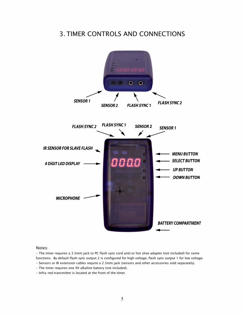
2. INTRODUCTION
The Universal Photo Timer is a hand-held photo flash and camera timer controller.
It contains the following functions:
WIRELESS SHUTTER RELEASEWIRELESS SHUTTER RELEASEWIRELESS SHUTTER RELEASEWIRELESS SHUTTER RELEASE AND TIMER AND TIMER AND TIMER AND TIMER
Acts as an infra-red wireless shutter release capable of instantly triggering the shutter
without disturbing the camera. It can be used for long exposures (bulb mode) with
many SLR cameras. The controller can also be programmed to be trigged at regular
intervals to perform time lapse photography.
CAMERA AND FLASH TRIGGERCAMERA AND FLASH TRIGGERCAMERA AND FLASH TRIGGERCAMERA AND FLASH TRIGGER
It allows you to trigger the shutter of your camera or fire an electronic flash with a
programmable delay in response to a trigger.
FLASH SLAVE UNITFLASH SLAVE UNITFLASH SLAVE UNITFLASH SLAVE UNIT
Acts as a flash slave. Select between normal flash or pre-flash synchronization used
with digital cameras.
Universal Photo Timer allows you to capture rare split second events such as falling
drops, popping balloons or ballistics shots. In addition, you can setup the timer for
unattended operation to help you capture wild life pictures, or perform time lapse
photography.
The timer learns infra-red codes from your existing camera remote. It comes pre-
programmed with Nikon and Cannon camera codes. As an option, you can connect the
Timer to your camera with a shutter release cable (refer to section 8 for more
information).
The timer contains a number of built-in sensors and functions allowing you to capture
special photographic effects. Refer to Quick Start Guide Section for more information.
This manual provides information allowing the user to operate more advanced functions
such as camera and flash trigger. It is a tool allowing photographers to perform high
speed captures or wild life photography.
The manual assumes good familiarity with your photographic equipment.
5
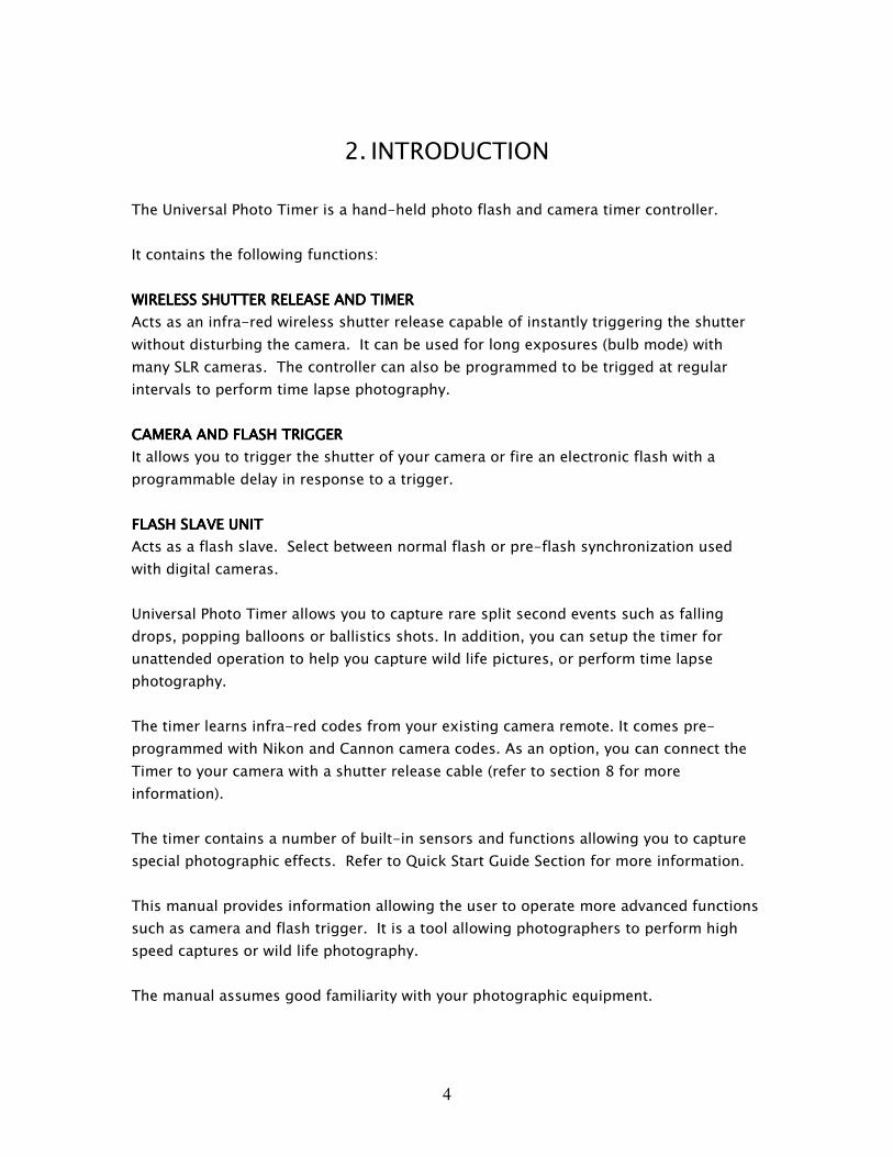
3. TIMER CONTROLS AND CONNECTIONS
Notes:
- The timer requires a 3.5mm jack to PC flash sync cord and/or hot shoe adapter (not included) for some
functions. By default flash sync output 2 is configured for high voltage, flash sync output 1 for low voltage.
- Sensors or IR extension cables require a 2.5mm jack (sensors and other accessories sold separately).
- The timer requires one 9V alkaline battery (not included).
- Infra-red transmitter is located at the front of the timer.
6
4. QUICK START GUIDE
� Guide to high speed photography.
� Using the timer as a wireless shutter release remote.
� Using the timer in bulb mode.
� Using the timer for time lapse photography.
� Using the timer as a flash slave.
� Learning new camera codes.
� Learning new flash codes.
The user interface consists of a 4 digit numeric LED display and four buttons. Buttons
include MENU (M), SELECT (S), UP (+) and DOWN (-).
The MENU button is used to turn the unit on. (If the timer does not turn on after
pressing the MENU button, please replace the battery.)
The MENU button is used to return to the main menu.
The SELECT button is used to navigate through parameters.
The UP and DOWN buttons are used for editing values and cycling through main
functions.
Refer to section 4 for more details on menus and configuration.
7
Guide to high speed photographyGuide to high speed photographyGuide to high speed photographyGuide to high speed photography
The goal of the high speed photography is capturing objects in motion. You can
photograph events that follow a predictable sequence. In all cases you want to be able
to detect a trigger, wait for an event and take a picture.
For example, in order to capture a falling drop hitting the surface of water, first you
need to detect the time when the drop starts falling. Next, you create a delay between
the trigger and the event. Finally you take the picture. This is where the Universal
Photo Timer is used.
There are two methods for performing high speed photography with the timer. The first
method uses a shutter of a camera. The second method uses an electronic flash.
The main advantage of the shutter method is that it can be used outdoors. The subject
and the background can be fully illuminated. However, since the shutter is used to
freeze the motion of the subject, it offers a limited speed. Maximum speed of a shutter
could range from 1/4000sec to 1/8000sec, in some cases it may not be fast enough
(fast moving objects will become blurred).
Moreover, in cameras that have a focal plane shutter, a small slit moves across the
photographic plane at much slower speeds (1/250), thus exposing different parts of the
photographic plane at slightly different times.
Finally, there is a delay between the shutter release and the actual exposure. It could be
as much 100ms or more (depending on camera). In addition there could be a small
variation in timing, each time the camera takes a picture. Therefore this method should
not be used when high timing accuracy is required.
A simple way of determining your camera shutter lag is to take a picture of a falling
object. Place a measuring tape in the background. You can calculate the time based on
the distance traveled and its known acceleration.
The second method of high speed photography is the flash method. The picture is
taken by opening the shutter of the camera, activating the flash and closing the shutter.
The picture needs to be taken in a dark room. Because the room is dark, the long
exposure time will not have any effect on the final output. The flash light duration now
becomes the actual exposure time.
The main advantage of the flash method is the exposure speed and better timing
consistency. Electronic flashes are capable of light strobes with durations of 1/10,000
or faster (lower the power setting of the flash, the shorter the flash duration).

8
The lag between the trigger and the flash strobe is insignificant. The disadvantage of
this method is that the picture needs to be taken in a dark room to avoid the over
exposure. Also since the flash is used to make the exposure, it may be more difficult to
provide a uniform lighting or to illuminate the background.
The timer contains a number of useful features that take advantage of the integrated
flash and camera control. In particular FL-2 camera mode allows you to automatically
open the camera shutter, activate the flash in response to a trigger and automatically
close it immediately after the flash is activated. Refer to Section 5 for more information.
Always take the first pictures at a wide angle to asses the timing. For example with
falling drops you want to start with short delay and roughly establish the delay before
zooming in and fine tuning the delay. Always start with short delay. Locate your object.
Increase the delay and observe the changes.
In all cases you want to be able to create a setup for your photography with consistent
timing. You want to be able to remove all variation in timing.
Setup your flash for manual mode. Some flash units have a stand-by mode (to conserve
power). Make sure to turn this feature off (so that that your flash is always turned on),
otherwise it takes an additional time for it to activate.
Camera setup is critical. You will need to set it up for manual mode with fixed aperture
and shutter speed. Focus your lens and turn off auto focus. Make sure that such
features as delayed exposure are turned off.
Picture preview in digital cameras is extremely useful, however it may change your
timing. It takes longer for your camera to activate the shutter when the picture preview
is displayed on the screen. You can turn off the automatic preview after an exposure or
just make sure than the last picture is not displayed while taking a new picture.
9
Using the Using the Using the Using the timertimertimertimer as as as as a a a a wireless shutter release remotewireless shutter release remotewireless shutter release remotewireless shutter release remote....
When using the timer as a wireless shutter release, configure the camera for infra-red
remote operation. Familiarize yourself with your camera and confirm the location of the
IR receiver. In remote mode, your camera will stay active for a limited time before it
switches to stand-by mode. Increase this timeout as needed.
The wireless shutter release works by sending an infra-red code to the camera (similar
to codes sent to your TV from your remote control). The best results are achieved when
operating the timer in the line of sight of the camera IR receiver. Test the operating
distance first, since it will vary depending on your camera model and ambient
conditions.
The following setup configures the timer as a wireless shutter release (verify and change
the settings if required):
• If you want trigger a camera that uses an IR code other than the pre-
programmed code in the timer - learn the required codes through Fn-4 menu
(refer later sections on code learning).
• Fn-4 -> CAM CODE -> select actual code to be used C1, C2, C3-N or C4-N or
ALL. This selects the IR code to be transmitted when triggering camera.
• Fn-3 -> SCALE -> 1000. This configures timing to be edited in 0.1 sec steps.
• Fn-3 - > SOURCE - > MAN. This selects manual operation – trigger occurs when
the user presses select button.
• Fn-3 -> DEAD TIME -> 000.1 – re-trigger can occur every 0.1sec
• Fn-3 -> INC DELAY -> 0000 – the auto delay increment is disabled.
• Fn-3 -> REPEAT -> 0000 – once triggers occurs there are no repeated
exposures.
• Fn-3 -> MODE > STND – single exposure, exposure time controlled by camera.
• Fn-3 -> BULB ZERO DEL -> YES. – in bulb mode, the delay from the trigger to
the camera exposure is zero.
• Fn-3 -> SHUTOFF -> 4H. – in trigger mode, the unit will turn itself off after 4
hours without user input. In setup menus the timeout remains 15 minutes.
• Fn-3 -> WAKEUP CAM -> OFF. – the unit contains a feature to automatically
take a picture so that the infra-red receiver in the camera does not time out.
This turns off the feature.
Once configured with the settings as described above, the timer will always power-up
with the same settings.
The following steps operate the shutter:
• Fn-1, press SELECT to accept
• You should see DELAY, 000.0. Press SELECT to accept
10
• You should see a small LED on the left side of the display blinking. You are
ready now to take pictures. Point the front of the timer towards the camera and
press the SELECT button.
• Press the MENU button to exit.
Using the Using the Using the Using the timertimertimertimer inininin bulb mode. bulb mode. bulb mode. bulb mode.
Follow camera and timer setup instructions for wireless shutter release remote.
Configure your camera for BULB mode. Your camera needs to support bulb mode, such
that the first IR code sent from remote opens the shutter, the second code closes the
shutter.
Configure one parameter differently: Fn-3 -> MODE -> BULB (instead of STND)
Once configured with settings as described above, the timer will always power-up with
those settings.
Follow the steps below to operate the shutter:
• Fn-1, press SELECT
• You should see BULB, 001.0s. Edit the value for required bulb time. Please note
that some cameras may have a maximum time limit for bulb mode. Press
SELECT
• You should see a small LED on the left side of the display blinking. You are
ready to take pictures. Point the front of the timer towards the camera and press
SELECT button on the timer. The transmitter needs to point towards the camera
during the entire exposure. Please take note of camera battery life when taking
long exposures. Very long exposures may require a noise reduction processing
at the end of exposure.
• Press MENU button to exit.
11
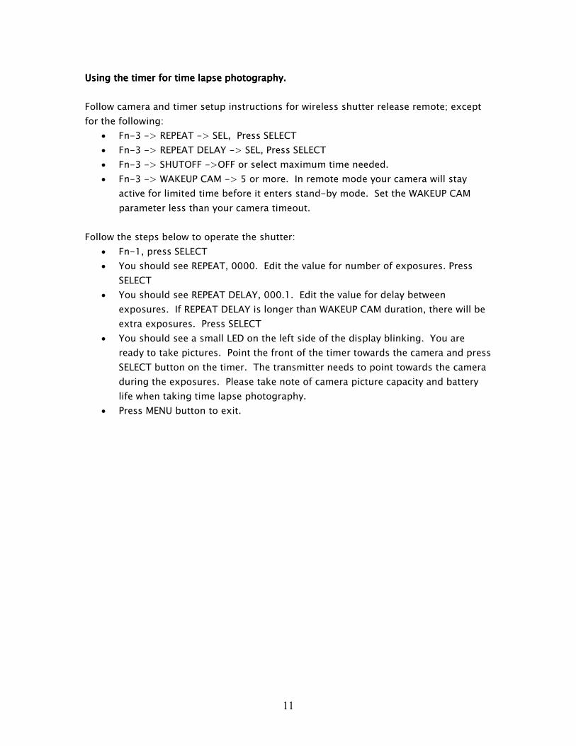
Using the Using the Using the Using the timertimertimertimer for time laps for time laps for time laps for time lapseeee photography. photography. photography. photography.
Follow camera and timer setup instructions for wireless shutter release remote; except
for the following:
• Fn-3 -> REPEAT -> SEL, Press SELECT
• Fn-3 -> REPEAT DELAY -> SEL, Press SELECT
• Fn-3 -> SHUTOFF ->OFF or select maximum time needed.
• Fn-3 -> WAKEUP CAM -> 5 or more. In remote mode your camera will stay
active for limited time before it enters stand-by mode. Set the WAKEUP CAM
parameter less than your camera timeout.
Follow the steps below to operate the shutter:
• Fn-1, press SELECT
• You should see REPEAT, 0000. Edit the value for number of exposures. Press
SELECT
• You should see REPEAT DELAY, 000.1. Edit the value for delay between
exposures. If REPEAT DELAY is longer than WAKEUP CAM duration, there will be
extra exposures. Press SELECT
• You should see a small LED on the left side of the display blinking. You are
ready to take pictures. Point the front of the timer towards the camera and press
SELECT button on the timer. The transmitter needs to point towards the camera
during the exposures. Please take note of camera picture capacity and battery
life when taking time lapse photography.
• Press MENU button to exit.
12
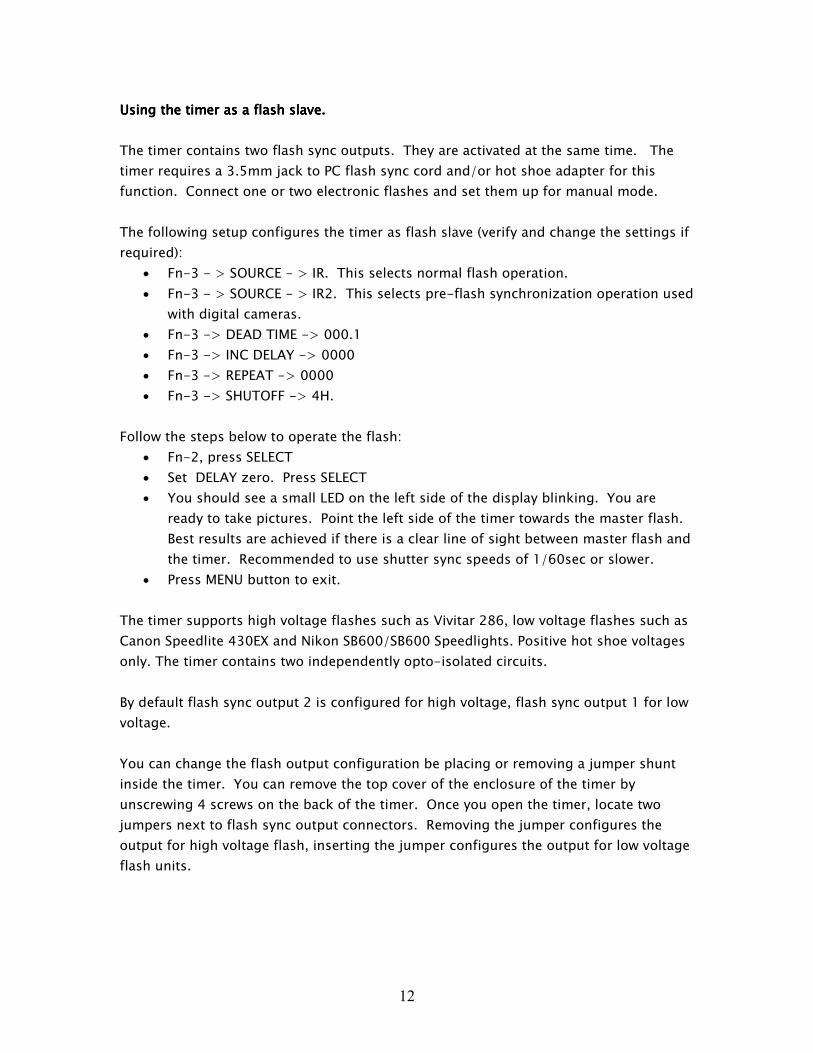
Using the Using the Using the Using the timertimertimertimer as a flash slave. as a flash slave. as a flash slave. as a flash slave.
The timer contains two flash sync outputs. They are activated at the same time. The
timer requires a 3.5mm jack to PC flash sync cord and/or hot shoe adapter for this
function. Connect one or two electronic flashes and set them up for manual mode.
The following setup configures the timer as flash slave (verify and change the settings if
required):
• Fn-3 - > SOURCE - > IR. This selects normal flash operation.
• Fn-3 - > SOURCE - > IR2. This selects pre-flash synchronization operation used
with digital cameras.
• Fn-3 -> DEAD TIME -> 000.1
• Fn-3 -> INC DELAY -> 0000
• Fn-3 -> REPEAT -> 0000
• Fn-3 -> SHUTOFF -> 4H.
Follow the steps below to operate the flash:
• Fn-2, press SELECT
• Set DELAY zero. Press SELECT
• You should see a small LED on the left side of the display blinking. You are
ready to take pictures. Point the left side of the timer towards the master flash.
Best results are achieved if there is a clear line of sight between master flash and
the timer. Recommended to use shutter sync speeds of 1/60sec or slower.
• Press MENU button to exit.
The timer supports high voltage flashes such as Vivitar 286, low voltage flashes such as
Canon Speedlite 430EX and Nikon SB600/SB600 Speedlights. Positive hot shoe voltages
only. The timer contains two independently opto-isolated circuits.
By default flash sync output 2 is configured for high voltage, flash sync output 1 for low
voltage.
You can change the flash output configuration be placing or removing a jumper shunt
inside the timer. You can remove the top cover of the enclosure of the timer by
unscrewing 4 screws on the back of the timer. Once you open the timer, locate two
jumpers next to flash sync output connectors. Removing the jumper configures the
output for high voltage flash, inserting the jumper configures the output for low voltage
flash units.
13
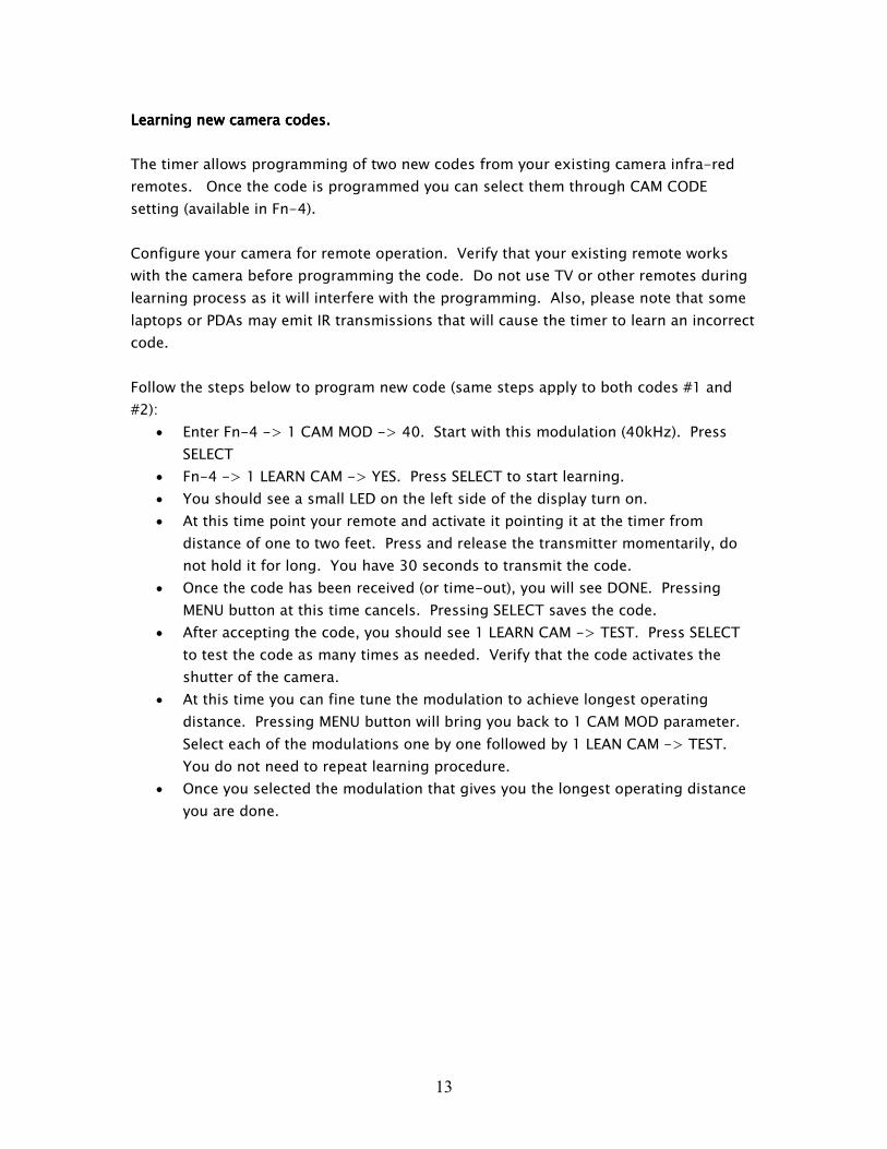
LearnLearnLearnLearninginginging new camera codes. new camera codes. new camera codes. new camera codes.
The timer allows programming of two new codes from your existing camera infra-red
remotes. Once the code is programmed you can select them through CAM CODE
setting (available in Fn-4).
Configure your camera for remote operation. Verify that your existing remote works
with the camera before programming the code. Do not use TV or other remotes during
learning process as it will interfere with the programming. Also, please note that some
laptops or PDAs may emit IR transmissions that will cause the timer to learn an incorrect
code.
Follow the steps below to program new code (same steps apply to both codes #1 and
#2):
• Enter Fn-4 -> 1 CAM MOD -> 40. Start with this modulation (40kHz). Press
SELECT
• Fn-4 -> 1 LEARN CAM -> YES. Press SELECT to start learning.
• You should see a small LED on the left side of the display turn on.
• At this time point your remote and activate it pointing it at the timer from
distance of one to two feet. Press and release the transmitter momentarily, do
not hold it for long. You have 30 seconds to transmit the code.
• Once the code has been received (or time-out), you will see DONE. Pressing
MENU button at this time cancels. Pressing SELECT saves the code.
• After accepting the code, you should see 1 LEARN CAM -> TEST. Press SELECT
to test the code as many times as needed. Verify that the code activates the
shutter of the camera.
• At this time you can fine tune the modulation to achieve longest operating
distance. Pressing MENU button will bring you back to 1 CAM MOD parameter.
Select each of the modulations one by one followed by 1 LEAN CAM -> TEST.
You do not need to repeat learning procedure.
• Once you selected the modulation that gives you the longest operating distance
you are done.
14
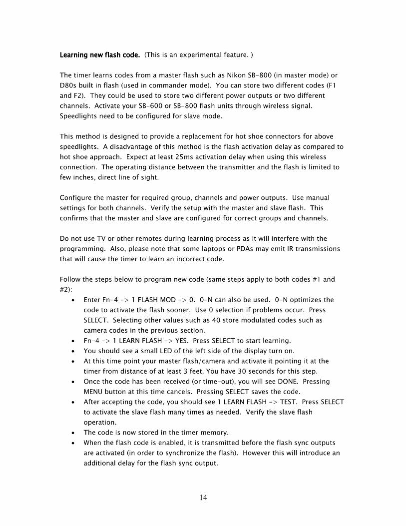
LearnLearnLearnLearninginginging new flash code. new flash code. new flash code. new flash code. (This is an experimental feature. )
The timer learns codes from a master flash such as Nikon SB-800 (in master mode) or
D80s built in flash (used in commander mode). You can store two different codes (F1
and F2). They could be used to store two different power outputs or two different
channels. Activate your SB-600 or SB-800 flash units through wireless signal.
Speedlights need to be configured for slave mode.
This method is designed to provide a replacement for hot shoe connectors for above
speedlights. A disadvantage of this method is the flash activation delay as compared to
hot shoe approach. Expect at least 25ms activation delay when using this wireless
connection. The operating distance between the transmitter and the flash is limited to
few inches, direct line of sight.
Configure the master for required group, channels and power outputs. Use manual
settings for both channels. Verify the setup with the master and slave flash. This
confirms that the master and slave are configured for correct groups and channels.
Do not use TV or other remotes during learning process as it will interfere with the
programming. Also, please note that some laptops or PDAs may emit IR transmissions
that will cause the timer to learn an incorrect code.
Follow the steps below to program new code (same steps apply to both codes #1 and
#2):
• Enter Fn-4 -> 1 FLASH MOD -> 0. 0-N can also be used. 0-N optimizes the
code to activate the flash sooner. Use 0 selection if problems occur. Press
SELECT. Selecting other values such as 40 store modulated codes such as
camera codes in the previous section.
• Fn-4 -> 1 LEARN FLASH -> YES. Press SELECT to start learning.
• You should see a small LED of the left side of the display turn on.
• At this time point your master flash/camera and activate it pointing it at the
timer from distance of at least 3 feet. You have 30 seconds for this step.
• Once the code has been received (or time-out), you will see DONE. Pressing
MENU button at this time cancels. Pressing SELECT saves the code.
• After accepting the code, you should see 1 LEARN FLASH -> TEST. Press SELECT
to activate the slave flash many times as needed. Verify the slave flash
operation.
• The code is now stored in the timer memory.
• When the flash code is enabled, it is transmitted before the flash sync outputs
are activated (in order to synchronize the flash). However this will introduce an
additional delay for the flash sync output.
15
5. DESCRIPTION OF MENUS
PRINCIPLES OF USER INTERFACEPRINCIPLES OF USER INTERFACEPRINCIPLES OF USER INTERFACEPRINCIPLES OF USER INTERFACE
The user interface consists of a 4 digit numeric LED display and four buttons. Buttons
include MENU (M), SELECT (S), UP (+) and DOWN (-). Scrolling text messages provide
intuitive and easy to navigate user menus.
The MENU button is used to turn on the timer. It is used to return to the main menu.
The SELECT button is used to navigate through parameters.
The UP and DOWN buttons are used for editing the values and cycling through main
functions. The timer contains two types of main functions: Fn-1 and Fn-2 are trigger
functions, Fn-3 and Fn-4 are configuration functions.
When editing a parameter, pressing UP or DOWN buttons will adjust the value by one.
Pressing and holding the button starts scrolling quickly through the numbers.
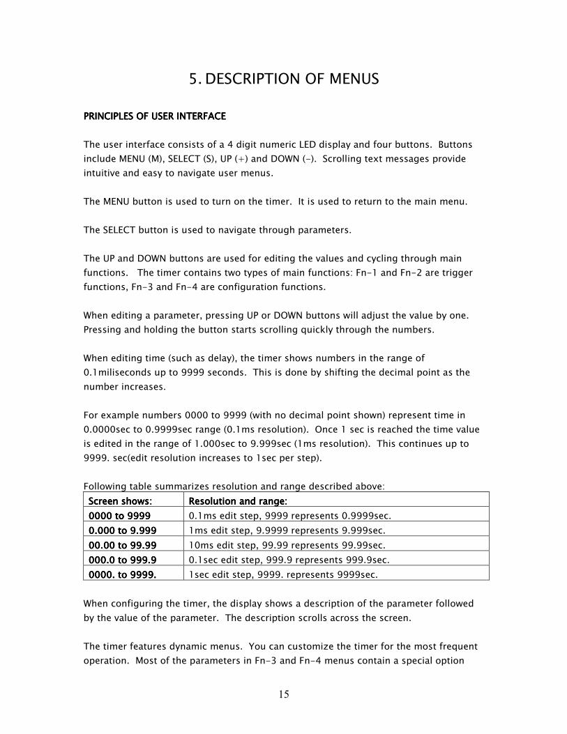
When editing time (such as delay), the timer shows numbers in the range of
0.1miliseconds up to 9999 seconds. This is done by shifting the decimal point as the
number increases.
For example numbers 0000 to 9999 (with no decimal point shown) represent time in
0.0000sec to 0.9999sec range (0.1ms resolution). Once 1 sec is reached the time value
is edited in the range of 1.000sec to 9.999sec (1ms resolution). This continues up to
9999. sec(edit resolution increases to 1sec per step).
Following table summarizes resolution and range described above:
Screen shows:Screen shows:Screen shows:Screen shows: Resolution and range:Resolution and range:Resolution and range:Resolution and range:
0000 to 99990000 to 99990000 to 99990000 to 9999 0.1ms edit step, 9999 represents 0.9999sec.
0000.000 to 9.999.000 to 9.999.000 to 9.999.000 to 9.999 1ms edit step, 9.9999 represents 9.999sec.
00000.00 to 99.990.00 to 99.990.00 to 99.990.00 to 99.99 10ms edit step, 99.99 represents 99.99sec.
000.0 to 999.9000.0 to 999.9000.0 to 999.9000.0 to 999.9 0.1sec edit step, 999.9 represents 999.9sec.
0000000000. to 9999.00. to 9999.00. to 9999.00. to 9999. 1sec edit step, 9999. represents 9999sec.
When configuring the timer, the display shows a description of the parameter followed
by the value of the parameter. The description scrolls across the screen.
The timer features dynamic menus. You can customize the timer for the most frequent
operation. Most of the parameters in Fn-3 and Fn-4 menus contain a special option
16
called SEL. When a parameter is set to this special value it will appear in Fn-1 and Fn-2,
otherwise the parameter is not shown.
Values configured through Fn-1 and Fn-2 menus are set temporarily. They will need to
be re-configured if powering down or after entering Fn-3 or Fn-4 menus.
Once the timer is configured and waiting for a trigger, the display turns off and blinks a
single LED to indicate readiness.
Pressing the MENU button exits trigger mode.
In configuration mode, the timer turns off after 15 minutes of inactivity.
17
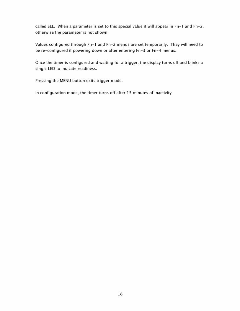
MAIN MENUMAIN MENUMAIN MENUMAIN MENU
Pressing UP and DOWN buttons switch between different functions. Pressing SELECT
enters the menu. Pressing MENU returns to Fn-1.
Main Menu:
FnFnFnFn----1 CAMERA TRIGGER MENU1 CAMERA TRIGGER MENU1 CAMERA TRIGGER MENU1 CAMERA TRIGGER MENU This menu is used to enter camera trigger menu. Use
this menu for wireless shutter release functionality.
FnFnFnFn----2 FLASH TRIGGER MENU2 FLASH TRIGGER MENU2 FLASH TRIGGER MENU2 FLASH TRIGGER MENU This menu is used to enter flash trigger menu. Use
this menu for flash functionality.
FnFnFnFn----3 SETUP MENU3 SETUP MENU3 SETUP MENU3 SETUP MENU This menu is used to configure the timer.
FnFnFnFn----4 CODES MENU4 CODES MENU4 CODES MENU4 CODES MENU This menu is used to select, learn and test camera
and flash codes used by the timer.
OFFOFFOFFOFF This turns off the timer.
18
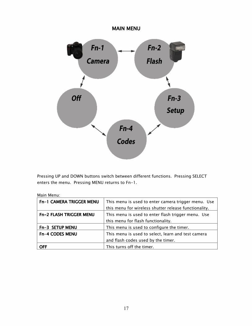
FnFnFnFn----1 1 1 1 CAMERA TRIGGER CAMERA TRIGGER CAMERA TRIGGER CAMERA TRIGGER MMMMENUENUENUENU
Pressing SELECT proceeds to the next parameter. Pressing UP and DOWN buttons edits
parameters. Pressing MENU returns to Fn-1. Parameters already pre-configured
through Fn-3 or Fn-4 menus will be hidden in this menu.
Configuration mode includes:
SOURCESOURCESOURCESOURCE Configures trigger source. (Visible only if set to SEL in Fn-3 menu.)
Select between following:
MANMANMANMAN manual trigger, press SELECT to trigger
MICMICMICMIC microphone trigger
IRIRIRIR infrared trigger, single pulse
IR2IR2IR2IR2 infrared trigger, dual pulse
LEVLEVLEVLEV sensor 1 OR sensor 2, level sensitive trigger
OROROROR sensor 1 OR sensor 2, edge sensitive trigger
ANDANDANDAND sensor 1 AND sensor 2, edge sensitive trigger
DISTDISTDISTDIST distance trigger, based on speed calculation between
sensor 1 and sensor 2 output.
19
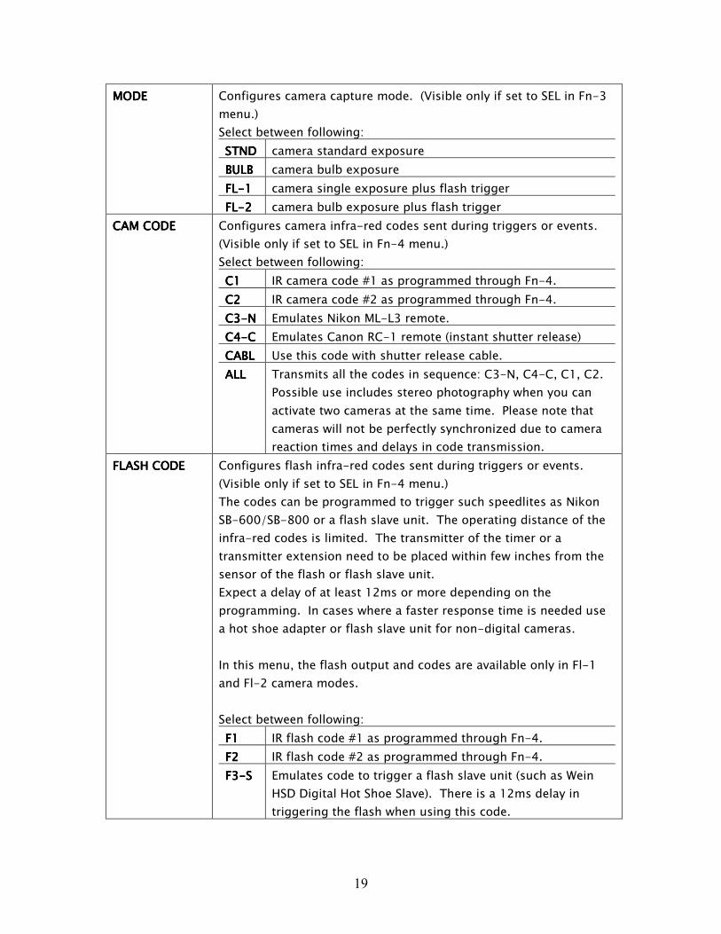
MODEMODEMODEMODE Configures camera capture mode. (Visible only if set to SEL in Fn-3
menu.)
Select between following:
STNDSTNDSTNDSTND camera standard exposure
BULBBULBBULBBULB camera bulb exposure
FLFLFLFL----1111 camera single exposure plus flash trigger
FLFLFLFL----2222 camera bulb exposure plus flash trigger
CAM CODECAM CODECAM CODECAM CODE Configures camera infra-red codes sent during triggers or events.
(Visible only if set to SEL in Fn-4 menu.)
Select between following:
C1C1C1C1 IR camera code #1 as programmed through Fn-4.
C2C2C2C2 IR camera code #2 as programmed through Fn-4.
C3C3C3C3----NNNN Emulates Nikon ML-L3 remote.
C4C4C4C4----CCCC Emulates Canon RC-1 remote (instant shutter release)
CABLCABLCABLCABL Use this code with shutter release cable.
ALLALLALLALL Transmits all the codes in sequence: C3-N, C4-C, C1, C2.
Possible use includes stereo photography when you can
activate two cameras at the same time. Please note that
cameras will not be perfectly synchronized due to camera
reaction times and delays in code transmission.
FLASH CODEFLASH CODEFLASH CODEFLASH CODE Configures flash infra-red codes sent during triggers or events.
(Visible only if set to SEL in Fn-4 menu.)
The codes can be programmed to trigger such speedlites as Nikon
SB-600/SB-800 or a flash slave unit. The operating distance of the
infra-red codes is limited. The transmitter of the timer or a
transmitter extension need to be placed within few inches from the
sensor of the flash or flash slave unit.
Expect a delay of at least 12ms or more depending on the
programming. In cases where a faster response time is needed use
a hot shoe adapter or flash slave unit for non-digital cameras.
In this menu, the flash output and codes are available only in Fl-1
and Fl-2 camera modes.
Select between following:
F1F1F1F1 IR flash code #1 as programmed through Fn-4.
F2F2F2F2 IR flash code #2 as programmed through Fn-4.
F3F3F3F3----SSSS Emulates code to trigger a flash slave unit (such as Wein
HSD Digital Hot Shoe Slave). There is a 12ms delay in
triggering the flash when using this code.
20
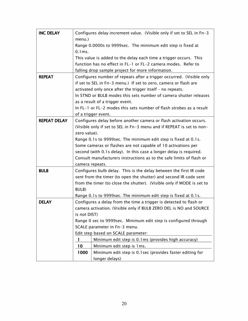
INC INC INC INC DELAYDELAYDELAYDELAY Configures delay increment value. (Visible only if set to SEL in Fn-3
menu.)
Range 0.0000s to 9999sec. The minimum edit step is fixed at
0.1ms.
This value is added to the delay each time a trigger occurs. This
function has no effect in FL-1 or FL-2 camera modes. Refer to
falling drop sample project for more information.
REPEATREPEATREPEATREPEAT Configures number of repeats after a trigger occurred. (Visible only
if set to SEL in Fn-3 menu.) If set to zero, camera or flash are
activated only once after the trigger itself – no repeats.
In STND or BULB modes this sets number of camera shutter releases
as a result of a trigger event.
In FL-1 or FL-2 modes this sets number of flash strobes as a result
of a trigger event.
REPEAT DELAYREPEAT DELAYREPEAT DELAYREPEAT DELAY Configures delay before another camera or flash activation occurs.
(Visible only if set to SEL in Fn-3 menu and if REPEAT is set to non-
zero value).
Range 0.1s to 9999sec. The minimum edit step is fixed at 0.1s.
Some cameras or flashes are not capable of 10 activations per
second (with 0.1s delay). In this case a longer delay is required.
Consult manufacturers instructions as to the safe limits of flash or
camera repeats.
BULBBULBBULBBULB Configures bulb delay. This is the delay between the first IR code
sent from the timer (to open the shutter) and second IR code sent
from the timer (to close the shutter). (Visible only if MODE is set to
BULB)
Range 0.1s to 9999sec. The minimum edit step is fixed at 0.1s.
DELAYDELAYDELAYDELAY Configures a delay from the time a trigger is detected to flash or
camera activation. (Visible only if BULB ZERO DEL is NO and SOURCE
is not DIST)
Range 0 sec to 9999sec. Minimum edit step is configured through
SCALE parameter in Fn-3 menu.
Edit step based on SCALE parameter:
1111 Minimum edit step is 0.1ms (provides high accuracy)
10101010 Minimum edit step is 1ms.
1000100010001000 Minimum edit step is 0.1sec (provides faster editing for
longer delays)
21
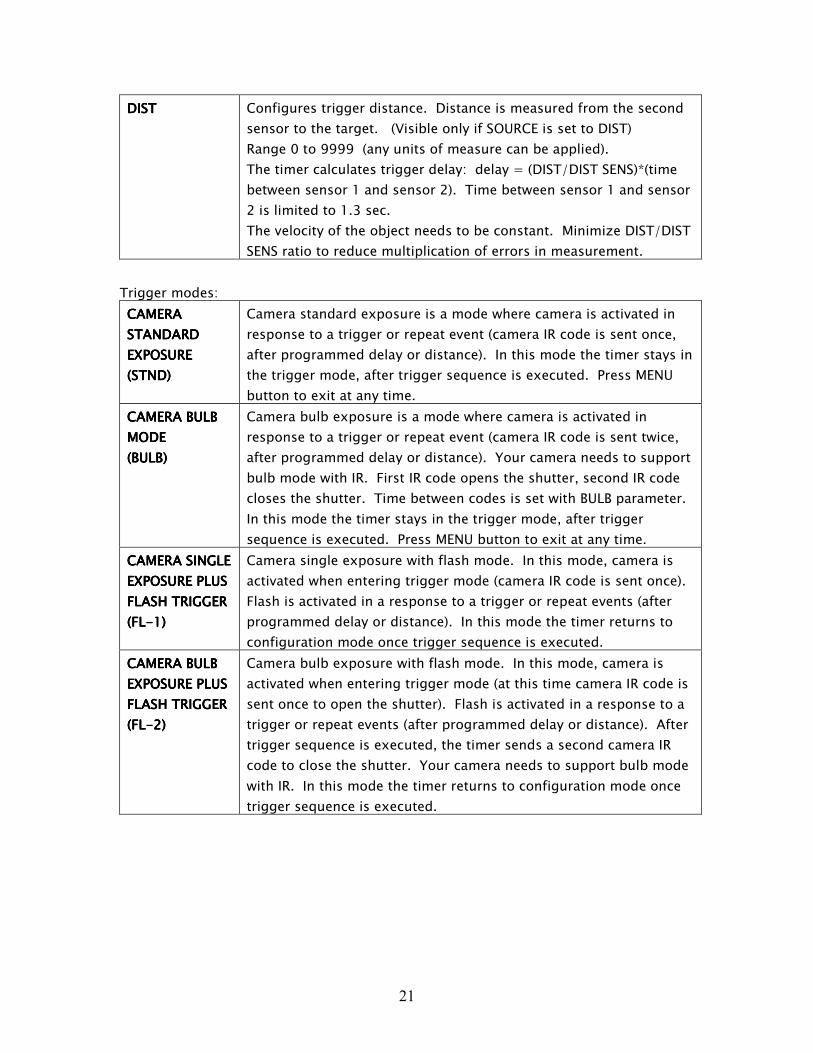
DISTDISTDISTDIST Configures trigger distance. Distance is measured from the second
sensor to the target. (Visible only if SOURCE is set to DIST)
Range 0 to 9999 (any units of measure can be applied).
The timer calculates trigger delay: delay = (DIST/DIST SENS)*(time
between sensor 1 and sensor 2). Time between sensor 1 and sensor
2 is limited to 1.3 sec.
The velocity of the object needs to be constant. Minimize DIST/DIST
SENS ratio to reduce multiplication of errors in measurement.
Trigger modes:
CAMERA CAMERA CAMERA CAMERA
STANDARDSTANDARDSTANDARDSTANDARD
EXPOSURE EXPOSURE EXPOSURE EXPOSURE
(STND)(STND)(STND)(STND)
Camera standard exposure is a mode where camera is activated in
response to a trigger or repeat event (camera IR code is sent once,
after programmed delay or distance). In this mode the timer stays in
the trigger mode, after trigger sequence is executed. Press MENU
button to exit at any time.
CAMERA BULB CAMERA BULB CAMERA BULB CAMERA BULB
MODE MODE MODE MODE
(BULB)(BULB)(BULB)(BULB)
Camera bulb exposure is a mode where camera is activated in
response to a trigger or repeat event (camera IR code is sent twice,
after programmed delay or distance). Your camera needs to support
bulb mode with IR. First IR code opens the shutter, second IR code
closes the shutter. Time between codes is set with BULB parameter.
In this mode the timer stays in the trigger mode, after trigger
sequence is executed. Press MENU button to exit at any time.
CAMERACAMERACAMERACAMERA SINGLE SINGLE SINGLE SINGLE
EXPOSURE PLUS EXPOSURE PLUS EXPOSURE PLUS EXPOSURE PLUS
FLASH TRIGGER FLASH TRIGGER FLASH TRIGGER FLASH TRIGGER
(FL(FL(FL(FL----1)1)1)1)
Camera single exposure with flash mode. In this mode, camera is
activated when entering trigger mode (camera IR code is sent once).
Flash is activated in a response to a trigger or repeat events (after
programmed delay or distance). In this mode the timer returns to
configuration mode once trigger sequence is executed.
CAMERA CAMERA CAMERA CAMERA BULB BULB BULB BULB
EXPOSURE PLUS EXPOSURE PLUS EXPOSURE PLUS EXPOSURE PLUS
FLASH TRIGGER FLASH TRIGGER FLASH TRIGGER FLASH TRIGGER
(FL(FL(FL(FL----2)2)2)2)
Camera bulb exposure with flash mode. In this mode, camera is
activated when entering trigger mode (at this time camera IR code is
sent once to open the shutter). Flash is activated in a response to a
trigger or repeat events (after programmed delay or distance). After
trigger sequence is executed, the timer sends a second camera IR
code to close the shutter. Your camera needs to support bulb mode
with IR. In this mode the timer returns to configuration mode once
trigger sequence is executed.
22
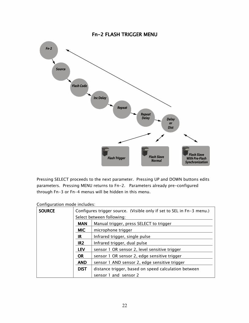
FnFnFnFn----2 2 2 2 FLASHFLASHFLASHFLASH TRIGGER TRIGGER TRIGGER TRIGGER MMMMENUENUENUENU
Pressing SELECT proceeds to the next parameter. Pressing UP and DOWN buttons edits
parameters. Pressing MENU returns to Fn-2. Parameters already pre-configured
through Fn-3 or Fn-4 menus will be hidden in this menu.
Configuration mode includes:
SOURCESOURCESOURCESOURCE Configures trigger source. (Visible only if set to SEL in Fn-3 menu.)
Select between following:
MANMANMANMAN Manual trigger, press SELECT to trigger
MICMICMICMIC microphone trigger
IRIRIRIR Infrared trigger, single pulse
IR2IR2IR2IR2 Infrared trigger, dual pulse
LEVLEVLEVLEV sensor 1 OR sensor 2, level sensitive trigger
OROROROR sensor 1 OR sensor 2, edge sensitive trigger
ANDANDANDAND sensor 1 AND sensor 2, edge sensitive trigger
DISTDISTDISTDIST distance trigger, based on speed calculation between
sensor 1 and sensor 2
23
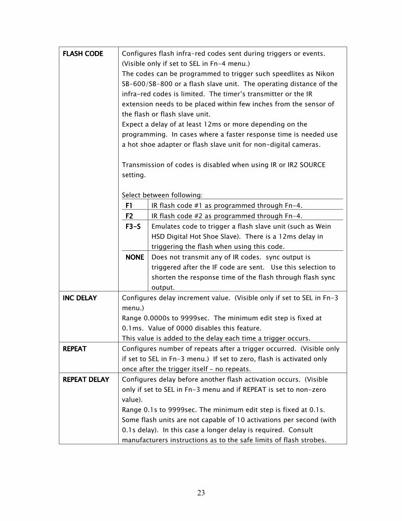
FLASH CODEFLASH CODEFLASH CODEFLASH CODE Configures flash infra-red codes sent during triggers or events.
(Visible only if set to SEL in Fn-4 menu.)
The codes can be programmed to trigger such speedlites as Nikon
SB-600/SB-800 or a flash slave unit. The operating distance of the
infra-red codes is limited. The timer’s transmitter or the IR
extension needs to be placed within few inches from the sensor of
the flash or flash slave unit.
Expect a delay of at least 12ms or more depending on the
programming. In cases where a faster response time is needed use
a hot shoe adapter or flash slave unit for non-digital cameras.
Transmission of codes is disabled when using IR or IR2 SOURCE
setting.
Select between following:
F1F1F1F1 IR flash code #1 as programmed through Fn-4.
F2F2F2F2 IR flash code #2 as programmed through Fn-4.
F3F3F3F3----SSSS Emulates code to trigger a flash slave unit (such as Wein
HSD Digital Hot Shoe Slave). There is a 12ms delay in
triggering the flash when using this code.
NONENONENONENONE Does not transmit any of IR codes. sync output is
triggered after the IF code are sent. Use this selection to
shorten the response time of the flash through flash sync
output.
INC INC INC INC DELAYDELAYDELAYDELAY Configures delay increment value. (Visible only if set to SEL in Fn-3
menu.)
Range 0.0000s to 9999sec. The minimum edit step is fixed at
0.1ms. Value of 0000 disables this feature.
This value is added to the delay each time a trigger occurs.
REPEATREPEATREPEATREPEAT Configures number of repeats after a trigger occurred. (Visible only
if set to SEL in Fn-3 menu.) If set to zero, flash is activated only
once after the trigger itself – no repeats.
REPEAT DELAYREPEAT DELAYREPEAT DELAYREPEAT DELAY Configures delay before another flash activation occurs. (Visible
only if set to SEL in Fn-3 menu and if REPEAT is set to non-zero
value).
Range 0.1s to 9999sec. The minimum edit step is fixed at 0.1s.
Some flash units are not capable of 10 activations per second (with
0.1s delay). In this case a longer delay is required. Consult
manufacturers instructions as to the safe limits of flash strobes.
24
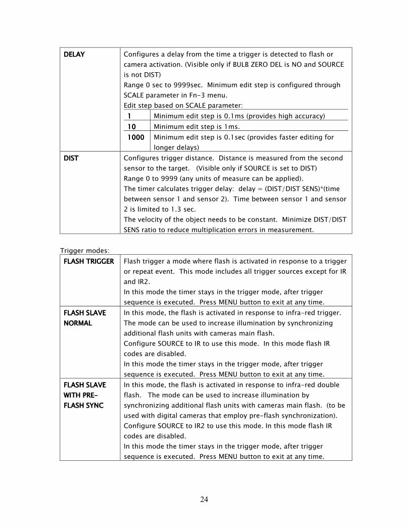
DELAYDELAYDELAYDELAY Configures a delay from the time a trigger is detected to flash or
camera activation. (Visible only if BULB ZERO DEL is NO and SOURCE
is not DIST)
Range 0 sec to 9999sec. Minimum edit step is configured through
SCALE parameter in Fn-3 menu.
Edit step based on SCALE parameter:
1111 Minimum edit step is 0.1ms (provides high accuracy)
10101010 Minimum edit step is 1ms.
1000100010001000 Minimum edit step is 0.1sec (provides faster editing for
longer delays)
DISTDISTDISTDIST Configures trigger distance. Distance is measured from the second
sensor to the target. (Visible only if SOURCE is set to DIST)
Range 0 to 9999 (any units of measure can be applied).
The timer calculates trigger delay: delay = (DIST/DIST SENS)*(time
between sensor 1 and sensor 2). Time between sensor 1 and sensor
2 is limited to 1.3 sec.
The velocity of the object needs to be constant. Minimize DIST/DIST
SENS ratio to reduce multiplication errors in measurement.
Trigger modes:
FLASH TRIGGERFLASH TRIGGERFLASH TRIGGERFLASH TRIGGER Flash trigger a mode where flash is activated in response to a trigger
or repeat event. This mode includes all trigger sources except for IR
and IR2.
In this mode the timer stays in the trigger mode, after trigger
sequence is executed. Press MENU button to exit at any time.
FLASH SLAVE FLASH SLAVE FLASH SLAVE FLASH SLAVE
NORMALNORMALNORMALNORMAL
In this mode, the flash is activated in response to infra-red trigger.
The mode can be used to increase illumination by synchronizing
additional flash units with cameras main flash.
Configure SOURCE to IR to use this mode. In this mode flash IR
codes are disabled.
In this mode the timer stays in the trigger mode, after trigger
sequence is executed. Press MENU button to exit at any time.
FLASH SLAVE FLASH SLAVE FLASH SLAVE FLASH SLAVE
WITH PREWITH PREWITH PREWITH PRE----
FLASH SYNCFLASH SYNCFLASH SYNCFLASH SYNC
In this mode, the flash is activated in response to infra-red double
flash. The mode can be used to increase illumination by
synchronizing additional flash units with cameras main flash. (to be
used with digital cameras that employ pre-flash synchronization).
Configure SOURCE to IR2 to use this mode. In this mode flash IR
codes are disabled.
In this mode the timer stays in the trigger mode, after trigger
sequence is executed. Press MENU button to exit at any time.
25
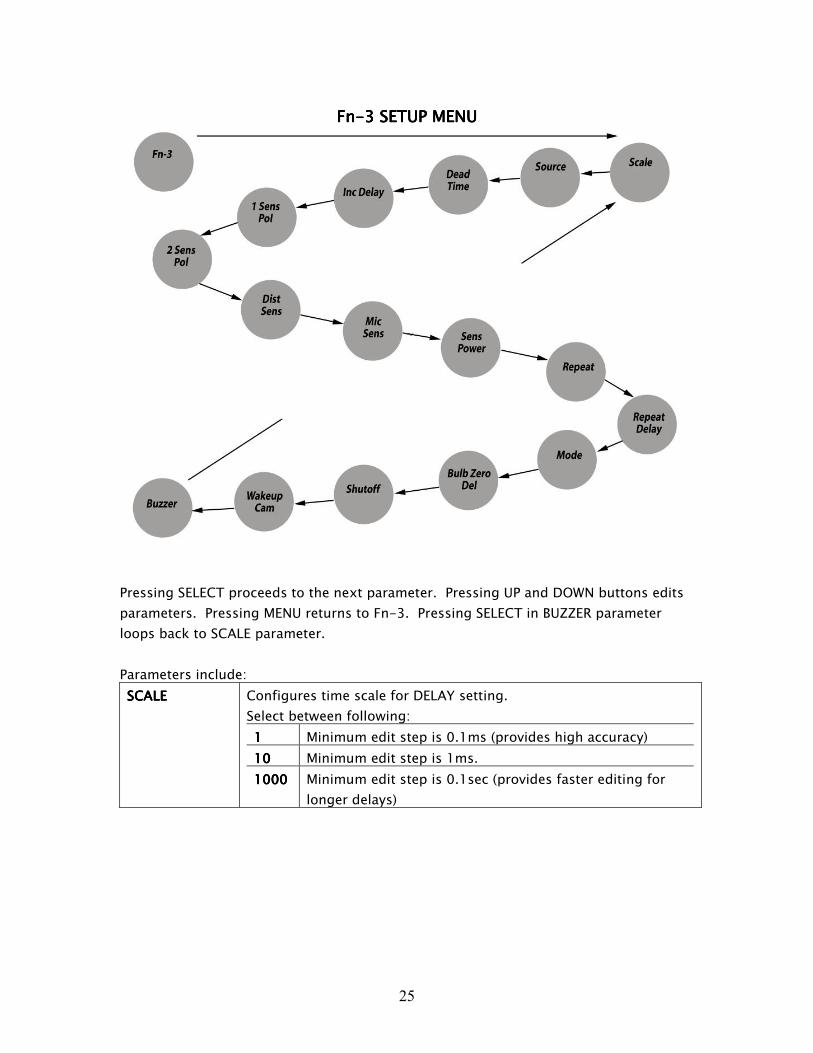
FnFnFnFn----3 SETUP3 SETUP3 SETUP3 SETUP MMMMENUENUENUENU
Pressing SELECT proceeds to the next parameter. Pressing UP and DOWN buttons edits
parameters. Pressing MENU returns to Fn-3. Pressing SELECT in BUZZER parameter
loops back to SCALE parameter.
Parameters include:
SCALESCALESCALESCALE Configures time scale for DELAY setting.
Select between following:
1111 Minimum edit step is 0.1ms (provides high accuracy)
10101010 Minimum edit step is 1ms.
1000100010001000 Minimum edit step is 0.1sec (provides faster editing for
longer delays)
26
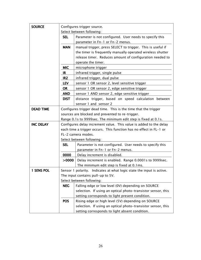
SOURCESOURCESOURCESOURCE Configures trigger source.
Select between following:
SELSELSELSEL Parameter is not configured. User needs to specify this
parameter in Fn-1 or Fn-2 menus.
MANMANMANMAN manual trigger, press SELECT to trigger. This is useful if
the timer is frequently manually operated wireless shutter
release timer. Reduces amount of configuration needed to
operate the timer.
MICMICMICMIC microphone trigger
IRIRIRIR infrared trigger, single pulse
IR2IR2IR2IR2 infrared trigger, dual pulse
LEVLEVLEVLEV sensor 1 OR sensor 2, level sensitive trigger
OROROROR sensor 1 OR sensor 2, edge sensitive trigger
ANDANDANDAND sensor 1 AND sensor 2, edge sensitive trigger
DISTDISTDISTDIST distance trigger, based on speed calculation between
sensor 1 and sensor 2
DEAD TIMEDEAD TIMEDEAD TIMEDEAD TIME Configures trigger dead time. This is the time that the trigger
sources are blocked and prevented to re-trigger.
Range 0.1s to 9999sec. The minimum edit step is fixed at 0.1s.
INC DELAYINC DELAYINC DELAYINC DELAY Configures delay increment value. This value is added to the delay
each time a trigger occurs. This function has no effect in FL-1 or
FL-2 camera modes.
Select between following:
SELSELSELSEL Parameter is not configured. User needs to specify this
parameter in Fn-1 or Fn-2 menus.
0000000000000000 Delay increment is disabled.
>0000>0000>0000>0000 Delay increment is enabled. Range 0.0001s to 9999sec.
The minimum edit step is fixed at 0.1ms.
1 SENS POL1 SENS POL1 SENS POL1 SENS POL Sensor 1 polarity. Indicates at what logic state the input is active.
The input contains pull-up to 5V.
Select between following:
NEGNEGNEGNEG Falling edge or low level (0V) depending on SOURCE
selection. If using an optical photo-transistor sensor, this
setting corresponds to light present condition.
POSPOSPOSPOS Rising edge or high level (5V) depending on SOURCE
selection. If using an optical photo-transistor sensor, this
setting corresponds to light absent condition.
27
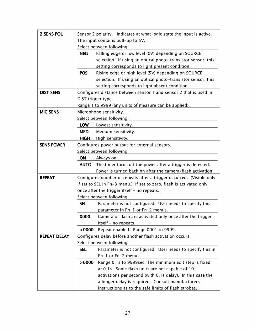
2 SENS2 SENS2 SENS2 SENS POL POL POL POL Sensor 2 polarity. Indicates at what logic state the input is active.
The input contains pull-up to 5V.
Select between following:
NEGNEGNEGNEG Falling edge or low level (0V) depending on SOURCE
selection. If using an optical photo-transistor sensor, this
setting corresponds to light present condition.
POSPOSPOSPOS Rising edge or high level (5V) depending on SOURCE
selection. If using an optical photo-transistor sensor, this
setting corresponds to light absent condition.
DIST SENSDIST SENSDIST SENSDIST SENS Configures distance between sensor 1 and sensor 2 that is used in
DIST trigger type.
Range 1 to 9999 (any units of measure can be applied).
MIC SENSMIC SENSMIC SENSMIC SENS Microphone sensitivity.
Select between following:
LOWLOWLOWLOW Lowest sensitivity.
MEDMEDMEDMED Medium sensitivity.
HIGHHIGHHIGHHIGH High sensitivity.
SENS POWERSENS POWERSENS POWERSENS POWER Configures power output for external sensors.
Select between following:
ONONONON Always on.
AUTOAUTOAUTOAUTO The timer turns off the power after a trigger is detected.
Power is turned back on after the camera/flash activation.
REPEATREPEATREPEATREPEAT Configures number of repeats after a trigger occurred. (Visible only
if set to SEL in Fn-3 menu.) If set to zero, flash is activated only
once after the trigger itself – no repeats.
Select between following:
SELSELSELSEL Parameter is not configured. User needs to specify this
parameter in Fn-1 or Fn-2 menus.
0000000000000000 Camera or flash are activated only once after the trigger
itself – no repeats.
>0000>0000>0000>0000 Repeat enabled. Range 0001 to 9999.
REPEAT DELAYREPEAT DELAYREPEAT DELAYREPEAT DELAY Configures delay before another flash activation occurs.
Select between following:
SELSELSELSEL Parameter is not configured. User needs to specify this in
Fn-1 or Fn-2 menus.
>0000>0000>0000>0000 Range 0.1s to 9999sec. The minimum edit step is fixed
at 0.1s. Some flash units are not capable of 10
activations per second (with 0.1s delay). In this case the
a longer delay is required. Consult manufacturers
instructions as to the safe limits of flash strobes.
28
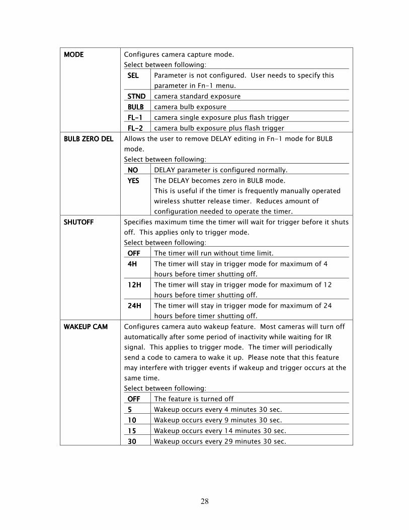
MODEMODEMODEMODE Configures camera capture mode.
Select between following:
SELSELSELSEL Parameter is not configured. User needs to specify this
parameter in Fn-1 menu.
STNDSTNDSTNDSTND camera standard exposure
BULBBULBBULBBULB camera bulb exposure
FLFLFLFL----1111 camera single exposure plus flash trigger
FLFLFLFL----2222 camera bulb exposure plus flash trigger
BULB ZERO DELBULB ZERO DELBULB ZERO DELBULB ZERO DEL Allows the user to remove DELAY editing in Fn-1 mode for BULB
mode.
Select between following:
NONONONO DELAY parameter is configured normally.
YESYESYESYES The DELAY becomes zero in BULB mode.
This is useful if the timer is frequently manually operated
wireless shutter release timer. Reduces amount of
configuration needed to operate the timer.
SHUTOFFSHUTOFFSHUTOFFSHUTOFF Specifies maximum time the timer will wait for trigger before it shuts
off. This applies only to trigger mode.
Select between following:
OFFOFFOFFOFF The timer will run without time limit.
4H4H4H4H The timer will stay in trigger mode for maximum of 4
hours before timer shutting off.
12H12H12H12H The timer will stay in trigger mode for maximum of 12
hours before timer shutting off.
24H24H24H24H The timer will stay in trigger mode for maximum of 24
hours before timer shutting off.
WAKEUP CAMWAKEUP CAMWAKEUP CAMWAKEUP CAM Configures camera auto wakeup feature. Most cameras will turn off
automatically after some period of inactivity while waiting for IR
signal. This applies to trigger mode. The timer will periodically
send a code to camera to wake it up. Please note that this feature
may interfere with trigger events if wakeup and trigger occurs at the
same time.
Select between following:
OFFOFFOFFOFF The feature is turned off
5555 Wakeup occurs every 4 minutes 30 sec.
10101010 Wakeup occurs every 9 minutes 30 sec.
15151515 Wakeup occurs every 14 minutes 30 sec.
30303030 Wakeup occurs every 29 minutes 30 sec.

29
BUZZERBUZZERBUZZERBUZZER Configures audible feedback of the timer. Includes button press and
trigger sounds.
Select between following:
OFFOFFOFFOFF The buzzer is disabled.
ONONONON The buzzer is enabled.

30
FnFnFnFn----4 CODES4 CODES4 CODES4 CODES MMMMENUENUENUENU
Pressing SELECT proceeds to the next parameter. Pressing UP and DOWN buttons edits
parameters. Pressing MENU returns to Fn-4.
Parameters include:
CAM CODECAM CODECAM CODECAM CODE Configures camera infra-red codes sent during triggers or events.
Select between following:
SELSELSELSEL Parameter is not configured. User needs to specify this
parameter in Fn-1 or Fn-2 menus.
C1C1C1C1 IR camera code #1
C2C2C2C2 IR camera code #2
C3C3C3C3----NNNN Emulates Nikon ML-L3 remote.
C4C4C4C4----CCCC Emulates Canon RC-1 remote (instant shutter release)
CABLCABLCABLCABL Use this code with shutter release cable.
ALLALLALLALL Transmits all the codes in sequence: C3-N, C4-C, C1, C2.
Please note that cameras will not be perfectly
synchronized due to camera reaction times and delays in
code transmission.
31
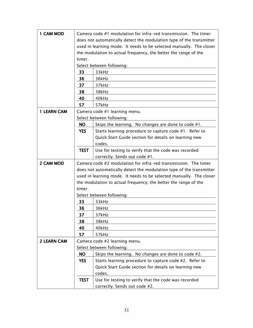
1 CAM MOD1 CAM MOD1 CAM MOD1 CAM MOD Camera code #1 modulation for infra-red transmission. The timer
does not automatically detect the modulation type of the transmitter
used in learning mode. It needs to be selected manually. The closer
the modulation to actual frequency, the better the range of the
timer.
Select between following:
33333333 33kHz
36363636 36kHz
37373737 37kHz
38383838 38kHz
40404040 40kHz
57575757 57kHz
1 LEARN CAM1 LEARN CAM1 LEARN CAM1 LEARN CAM Camera code #1 learning menu.
Select between following:
NONONONO Skips the learning. No changes are done to code #1.
YESYESYESYES Starts learning procedure to capture code #1. Refer to
Quick Start Guide section for details on learning new
codes.
TESTTESTTESTTEST Use for testing to verify that the code was recorded
correctly. Sends out code #1.
2222 CAM MOD CAM MOD CAM MOD CAM MOD Camera code #2 modulation for infra-red transmission. The timer
does not automatically detect the modulation type of the transmitter
used in learning mode. It needs to be selected manually. The closer
the modulation to actual frequency, the better the range of the
timer.
Select between following:
33333333 33kHz
36363636 36kHz
37373737 37kHz
38383838 38kHz
40404040 40kHz
57575757 57kHz
2 LEARN CAM2 LEARN CAM2 LEARN CAM2 LEARN CAM Camera code #2 learning menu.
Select between following:
NONONONO Skips the learning. No changes are done to code #2.
YESYESYESYES Starts learning procedure to capture code #2. Refer to
Quick Start Guide section for details on learning new
codes.
TESTTESTTESTTEST Use for testing to verify that the code was recorded
correctly. Sends out code #2.
32
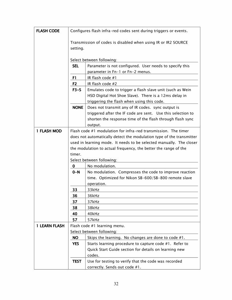
FLASH CODEFLASH CODEFLASH CODEFLASH CODE Configures flash infra-red codes sent during triggers or events.
Transmission of codes is disabled when using IR or IR2 SOURCE
setting.
Select between following:
SELSELSELSEL Parameter is not configured. User needs to specify this
parameter in Fn-1 or Fn-2 menus.
F1F1F1F1 IR flash code #1
F2F2F2F2 IR flash code #2
F3F3F3F3----SSSS Emulates code to trigger a flash slave unit (such as Wein
HSD Digital Hot Shoe Slave). There is a 12ms delay in
triggering the flash when using this code.
NONENONENONENONE Does not transmit any of IR codes. sync output is
triggered after the IF code are sent. Use this selection to
shorten the response time of the flash through flash sync
output.
1 FLASH MOD1 FLASH MOD1 FLASH MOD1 FLASH MOD Flash code #1 modulation for infra-red transmission. The timer
does not automatically detect the modulation type of the transmitter
used in learning mode. It needs to be selected manually. The closer
the modulation to actual frequency, the better the range of the
timer.
Select between following:
0000 No modulation.
0000----NNNN No modulation. Compresses the code to improve reaction
time. Optimized for Nikon SB-600/SB-800 remote slave
operation.
33333333 33kHz
36363636 36kHz
37373737 37kHz
38383838 38kHz
40404040 40kHz
57575757 57kHz
1 LEARN FLASH1 LEARN FLASH1 LEARN FLASH1 LEARN FLASH Flash code #1 learning menu.
Select between following:
NONONONO Skips the learning. No changes are done to code #1.
YESYESYESYES Starts learning procedure to capture code #1. Refer to
Quick Start Guide section for details on learning new
codes.
TESTTESTTESTTEST Use for testing to verify that the code was recorded
correctly. Sends out code #1.

33
2 FLASH MOD2 FLASH MOD2 FLASH MOD2 FLASH MOD Flash code #2 modulation for infra-red transmission. The timer
does not automatically detect the modulation type of the transmitter
used in learning mode. It needs to be selected manually. The closer
the modulation to actual frequency, the better the range of the
timer.
Select between following:
0000 No modulation.
0000----NNNN No modulation. Compresses the code to improve reaction
time. Optimized for Nikon SB-600/SB-800 remote slave
operation.
33333333 33kHz
36363636 36kHz
37373737 37kHz
38383838 38kHz
40404040 40kHz
57575757 57kHz
2 LEARN FLASH2 LEARN FLASH2 LEARN FLASH2 LEARN FLASH Flash code #2 learning menu.
Select between following:
NONONONO Skips the learning. No changes are done to code #2.
YESYESYESYES Starts learning procedure to capture code #2. Refer to
Quick Start Guide section for details on learning new
codes.
TESTTESTTESTTEST Use for testing to verify that the code was recorded
correctly. Sends out code #2.

34
6. SPECIFICATIONS
Three products in one:Three products in one:Three products in one:Three products in one: WIRELESS SHUTTER RELEASE AND TIMER, CAMERA AND FLASH
TRIGGER, FLASH SLAVE UNIT
Wireless Shutter ReleaseWireless Shutter ReleaseWireless Shutter ReleaseWireless Shutter Release And Timer: And Timer: And Timer: And Timer: Acts as an infra-red wireless shutter release
capable of instantly triggering the shutter without disturbing the camera. It can be used
for long time exposures (bulb mode) with many SLR cameras. The controller can also
be programmed to trip at regular intervals to perform time lapse photography. Provides
most of the functionality of a programmable photographic timer such as Canon TC-
80N3 or Nikon MC-36 timers (done thorough infra-red code emulation, no cord). The
exposure is delayed by your camera shutter lag.
Camera And Flash TriggerCamera And Flash TriggerCamera And Flash TriggerCamera And Flash Trigger: : : : It allows you to trip the shutter of your camera or fire an
electronic flash with a programmable delay in response to a trigger.
Triggering includes: manual, microphone, infra-red, combination of triggers from
external sensors, trigger based on distance and speed measurement.
Flash Slave UnitFlash Slave UnitFlash Slave UnitFlash Slave Unit: : : : Acts as flash slave. Selectable between normal flash or pre-flash
synchronization used with digital cameras. Indoor range up to 45 ft.
Flash output:Flash output:Flash output:Flash output: Two 3.5mm jacks for photo flash units. Two parallel, but independently
opto-isolated circuits with 300V rating. The timer requires a 3.5mm jack to PC flash
sync cord and/or hot shoe adapter (not included) when using flash. Supports high
voltage flashes such as Vivitar 286, low voltage flashes such as Canon Speedlite 430EX
and Nikon SB600/SB600 Speedlights. Positive hot shoe voltages only.
Sensor connections:Sensor connections:Sensor connections:Sensor connections: Two 2.5mm jacks for external sensors or IR extension cables
(sensors and other accessories not included). Programmable sensor polarity. The timer
can be triggered with different combinations of the sensor input: sensor 1 AND sensor 2
edge trigger, sensor 1 OR sensor 2 edge trigger, sensor 1 OR sensor 2 level trigger,
sensor 1 and sensor 2 distance calculation. Sensor signal needs to be active for at least
25us.
InterfaceInterfaceInterfaceInterface:::: 4 digit LED display, 4 button interface. Buzzer is used to provide audible
feedback. Scrolling text messages provide intuitive and easy to navigate user menus.
Dynamic configurable menus to customize for most frequent operation.
Built in components: Built in components: Built in components: Built in components: Built in microphone and infra-red sensor.
35
Number of programmable camera codes:Number of programmable camera codes:Number of programmable camera codes:Number of programmable camera codes: Two programmable IR camera codes. Camera
code selectable modulation 33kHz, 36kHz, 37kHz, 38kHz, 40kHz, 57kHz. Learns IR
codes from your own IR camera transmitter (codes with up to 40 bits of data)
Number of programmable flash codes:Number of programmable flash codes:Number of programmable flash codes:Number of programmable flash codes: Two programmable IR flash codes. Learns
remote trigger flash codes used in Nikon SB-800 and SB-600 speedlites. Allows the
timer to trigger the speedlite or flash save unit (short operating distance) In some cases
eliminating the need for a hot shoe adapter and a sync cable. This is an experimental
feature.
PrePrePrePre----programmed camera remotes:programmed camera remotes:programmed camera remotes:programmed camera remotes: 2 pre-programmed camera remote codes:
Preprogrammed with Nikon ML-L3 Remote Control Code. (used with Nikon SLRs
D40(x)/D50/D60/D70s/D80). Pre-programmed with Canon RC-1 Remote Control
instant release code. (used with EOS 10s, Elan/II/IIE & 7/E, Rebel K2, Ti & T2 (Date
Model Only), Digital Rebel and IX Series Cameras)
Time adjustment limits, accuracy and response timTime adjustment limits, accuracy and response timTime adjustment limits, accuracy and response timTime adjustment limits, accuracy and response time: e: e: e: Trigger delay adjustments done in
100us resolution. Repeat exposure and bulb time adjustments done in 100ms
resolution. Adjustments done up to 9999 seconds. Accuracy of delays to within 100us
or 1% whichever is greater. Response time for the built in microphone is within 0.5ms.
Environmental operating conditions:Environmental operating conditions:Environmental operating conditions:Environmental operating conditions: Ambient temperature +32 to 104 deg F (0 to 40
deg Celsius), max humidity 85% non-condensing.
Management Features:Management Features:Management Features:Management Features: Auto shutoff timer selectable between always on, 4 hours, 8
hours or 24 hours. Camera auto wakeup feature, prevents the camera entering sleep
mode. Takes picture while waiting for a trigger. Wakeup is selectable between off,
5min, 10min, 15min, 30min.
Power SourcePower SourcePower SourcePower Source:::: Operates from 9V alkaline battery. Battery life: up to 40 hours (ambient
temperature 20 degC). The battery life also depends on the accessories connected. If
there is a current drain through one of the external sensor connections, the battery life
will be reduced.
Weight (without batteryWeight (without batteryWeight (without batteryWeight (without battery and cables and cables and cables and cables):):):): Approx. 3.5 oz. ( 100g )
Dimensions (Dimensions (Dimensions (Dimensions (L L L L x x x x WWWW x x x x HHHH):):):): 4.94" x 2.75" x 0.94" (125.5mm x 69.9mm x 23.9mm)

36
The information presented in this document is for informational purposes only and may
contain technical inaccuracies, omissions and typographical errors. Universal Timer Ltd.
reserves the right to revise this information and to make changes from time to time to
the content hereof without obligation of Universal Timer Ltd. to notify any person of
such revisions and changes.
Camera and Flash are not included with the timer. Laser pointers are not included with
the timer.
Hot shoe adapter, IR extension cable and optical phototransistor sensor are not included
with the timer. They can be purchased separately. Please contact us through email
[email protected] for more information.
The timer allows photographers to create elaborate setups and interface custom
sensors. It is left up to the individual photographer to build and connect them. Some
technical skills are required for advanced features.
Nikon is a registered trademark of Nikon Corporation. Canon is a registered trademark
of Canon Corporation.
37
7. SAMPLE PROJECTS
The examples below illustrate the use of Universal Photo Timer:
FALLING DROPFALLING DROPFALLING DROPFALLING DROP
In this example I captured a falling drop in various stages of its fall. I turned on a
faucet so that a drop would fall every 2 seconds.
For this project I used the following components:
• Camera and flash.
• Universal Photo Timer.
• Phototransistor and external sensor cable with 2.5mm plug.
• Laser pointer.
• Dripping faucet.
I used Nikon D80 with Nikon Micro lens 60mm f/2.8 and Nikon SB-600 for background
illumination. The lens was manually focused. The camera was set for manual mode
with aperture of f/8 and shutter speed of 1/200s, ISO 100. Remote receiver enabled.
Built in flash of D80 was configured for commander mode so that SB-600 would turn on
during exposure, to improve lighting.
Universal Photo Timer was used to activate the camera (I did not need a darkroom for
this). To trigger the timer I used a standard off the shelf laser pointer as the light
source and an optical sensor to detect the presence or absence of a laser beam. The
optical sensor was connected to SENSOR 1 of the timer.
I placed the laser and the sensor several feet away. The laser was pointed at the tip of
the faucet and at the sensor. As the drop was forming, the laser beam was deflected.
As the drop fell, the laser beam returned to the sensor thus triggering the timer.
I configured the timer for camera mode trigger (Fn-1) with SOURCE set to OR and MODE
set to STND. Sensor polarity: 1 SENS POL was set to NEG and DEAD TIME was set to 1.0
sec.
Since the shutter lag of the camera is approx 100ms, it is impossible to take the picture
of the falling drop that has just triggered the sensor. Since the drops are forming at the
constant rate (roughly 2sec), I decided to trigger on one drop and take the picture of the
following drop.
38
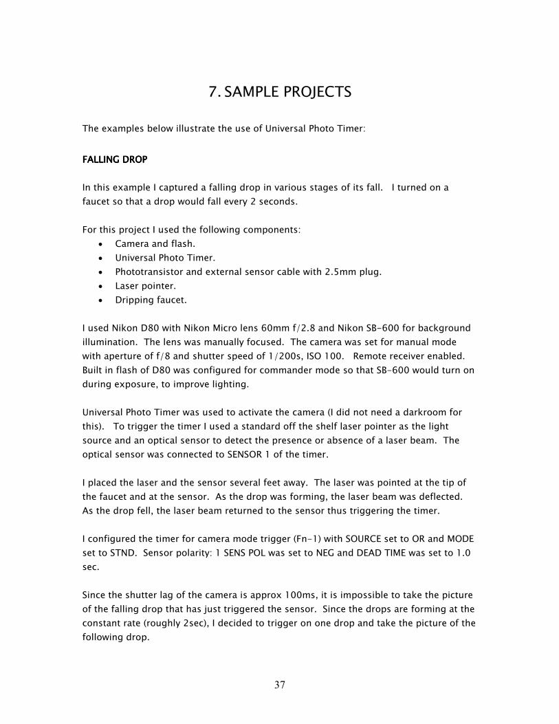
I set the delay to approx 2 sec and was able to take pictures of the drop as it was just
about to fall. Since I wanted to capture a sequence of exposures of a falling drop in
various stages of its fall, I configured INC DELAY parameter to increment delay after
each trigger.
This allowed me to capture this sequence as illustrated below (four exposures combined
into a single picture using a picture editing software):
Notes:
Please observe manufacturer safety precautions when handling lasers.
39
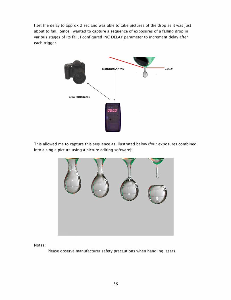
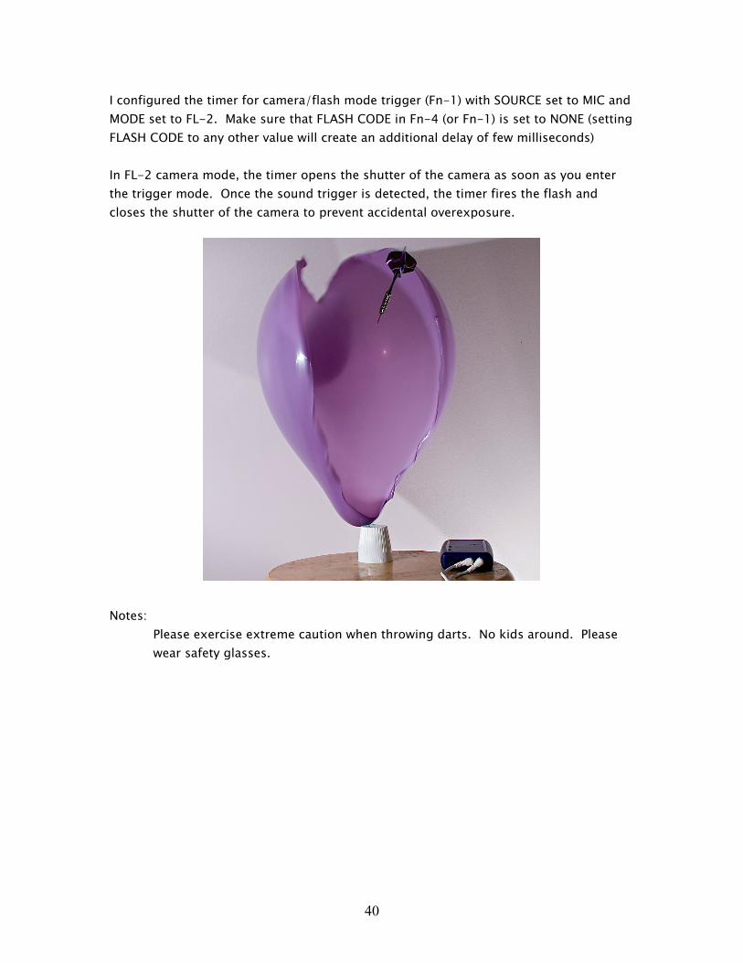
POPPING POPPING POPPING POPPING BALLOONBALLOONBALLOONBALLOONSSSS
In this example I captured a popping balloon. The balloon was punctured with a dart.
The picture is taken in a dark room. The flash is the only source of light in the room.
The sound of a popped balloon triggers the built-in microphone activating the flash. It
is a matter of few milliseconds for the balloon to completely collapse once punctured.
The entire event is so fast that even increasing the distance between the balloon and the
microphone can significantly delay the exposure (the sound takes longer to reach the
microphone). The timer delay is set to zero to allow fastest reaction time.
For this project I used the following components:
• Camera and flash. Flash connected to Universal Photo Timer with flash sync
cable.
• Universal Photo Timer.
• Balloon and darts.
I used Nikon D80 with Nikon 18-135 f/3.5-4.5 lens and two electronic flashes for
foreground and background illumination. The lens was manually focused. The camera
was set for manual mode with aperture of f/8 and bulb mode, ISO 100. Remote receiver
enabled.
Setup your flash for manual mode, as low power as possible – this increases the speed
of the exposure reducing motion blur of the collapsing balloon. Also, make sure to turn
off standby mode in your flash.
40
I configured the timer for camera/flash mode trigger (Fn-1) with SOURCE set to MIC and
MODE set to FL-2. Make sure that FLASH CODE in Fn-4 (or Fn-1) is set to NONE (setting
FLASH CODE to any other value will create an additional delay of few milliseconds)
In FL-2 camera mode, the timer opens the shutter of the camera as soon as you enter
the trigger mode. Once the sound trigger is detected, the timer fires the flash and
closes the shutter of the camera to prevent accidental overexposure.
Notes:
Please exercise extreme caution when throwing darts. No kids around. Please
wear safety glasses.
41
8. CONNECTION DIAGRAMS
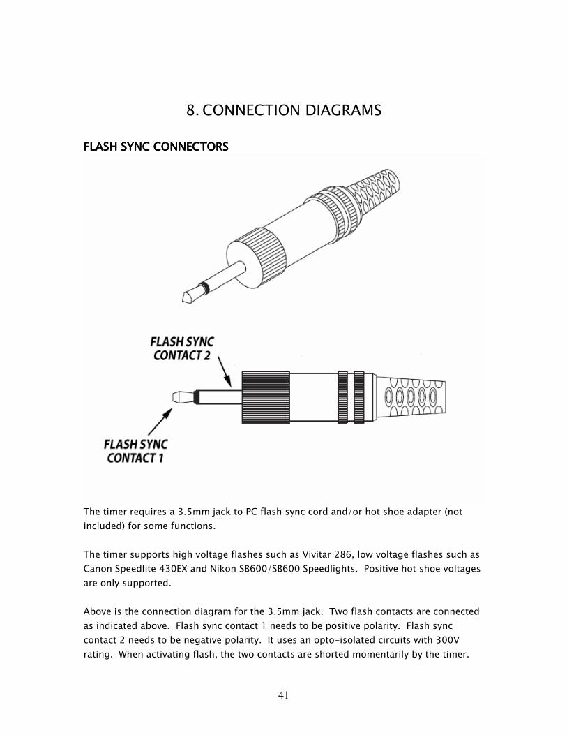
FLASH SYNC CONNECTORSFLASH SYNC CONNECTORSFLASH SYNC CONNECTORSFLASH SYNC CONNECTORS
The timer requires a 3.5mm jack to PC flash sync cord and/or hot shoe adapter (not
included) for some functions.
The timer supports high voltage flashes such as Vivitar 286, low voltage flashes such as
Canon Speedlite 430EX and Nikon SB600/SB600 Speedlights. Positive hot shoe voltages
are only supported.
Above is the connection diagram for the 3.5mm jack. Two flash contacts are connected
as indicated above. Flash sync contact 1 needs to be positive polarity. Flash sync
contact 2 needs to be negative polarity. It uses an opto-isolated circuits with 300V
rating. When activating flash, the two contacts are shorted momentarily by the timer.
42
Two flash sync connections have two separate electrically isolated circuits. They are
both activated at the same time.
By default flash sync output 2 is configured for high voltage, flash sync output 1 for low
voltage. The circuits are able to withstand 300V regardless of configuration.
You can change the flash output configuration be closing or opening a jumper inside the
timer. You can remove the top cover of the enclosure of the timer by unscrewing 4
screws on the back of the timer. Once you open the timer, locate two jumpers next to
flash sync output connectors. Removing the jumper configures the output for high
voltage flash, inserting the jumper shunt configures the output for low voltage flash
units.
For example if you require two high voltage flash sync outputs remove (or open) both
jumpers.
43
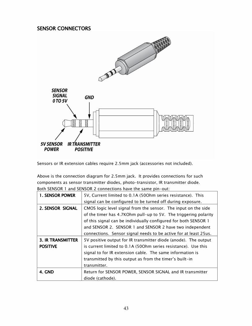
SENSOR CONNECTORSSENSOR CONNECTORSSENSOR CONNECTORSSENSOR CONNECTORS
Sensors or IR extension cables require 2.5mm jack (accessories not included).
Above is the connection diagram for 2.5mm jack. It provides connections for such
components as sensor transmitter diodes, photo-transistor, IR transmitter diode.
Both SENSOR 1 and SENSOR 2 connections have the same pin-out:
1. 1. 1. 1. SENSOR POWERSENSOR POWERSENSOR POWERSENSOR POWER 5V, Current limited to 0.1A (50Ohm series resistance). This
signal can be configured to be turned off during exposure.
2. 2. 2. 2. SENSOR SIGNALSENSOR SIGNALSENSOR SIGNALSENSOR SIGNAL CMOS logic level signal from the sensor. The input on the side
of the timer has 4.7KOhm pull-up to 5V. The triggering polarity
of this signal can be individually configured for both SENSOR 1
and SENSOR 2. SENSOR 1 and SENSOR 2 have two independent
connections. Sensor signal needs to be active for at least 25us.
3. 3. 3. 3. IR TRANSMITTER IR TRANSMITTER IR TRANSMITTER IR TRANSMITTER
POSITIVEPOSITIVEPOSITIVEPOSITIVE
5V positive output for IR transmitter diode (anode). The output
is current limited to 0.1A (50Ohm series resistance). Use this
signal to for IR extension cable. The same information is
transmitted by this output as from the timer’s built-in
transmitter.
4. 4. 4. 4. GNDGNDGNDGND Return for SENSOR POWER, SENSOR SIGNAL and IR transmitter
diode (cathode).
44
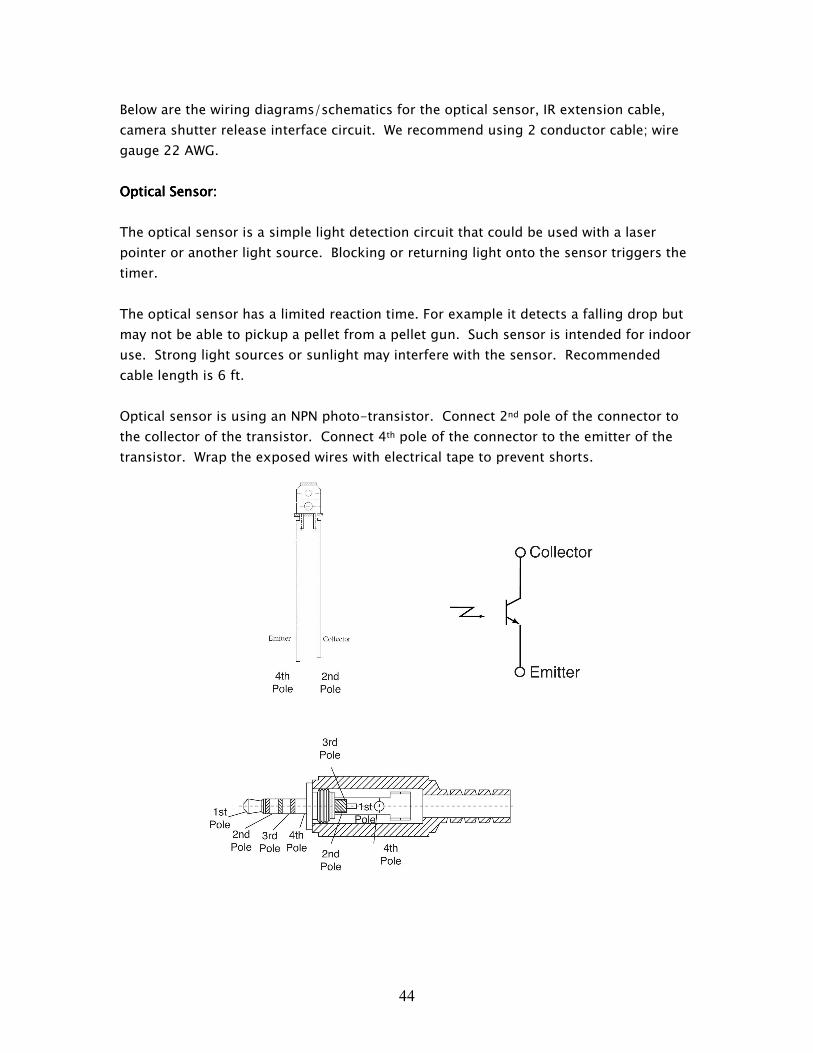
Below are the wiring diagrams/schematics for the optical sensor, IR extension cable,
camera shutter release interface circuit. We recommend using 2 conductor cable; wire
gauge 22 AWG.
Optical Sensor:Optical Sensor:Optical Sensor:Optical Sensor:
The optical sensor is a simple light detection circuit that could be used with a laser
pointer or another light source. Blocking or returning light onto the sensor triggers the
timer.
The optical sensor has a limited reaction time. For example it detects a falling drop but
may not be able to pickup a pellet from a pellet gun. Such sensor is intended for indoor
use. Strong light sources or sunlight may interfere with the sensor. Recommended
cable length is 6 ft.
Optical sensor is using an NPN photo-transistor. Connect 2nd pole of the connector to
the collector of the transistor. Connect 4th pole of the connector to the emitter of the
transistor. Wrap the exposed wires with electrical tape to prevent shorts.

45
IR extension IR extension IR extension IR extension cable:cable:cable:cable:
The timer triggers camera shutter using an infra-red transmission. This is similar to
transmission used by your TV remote. It has limited operating distance and does not
work around corners. Direct sunlight or strong light sources may also reduce the
effective range. This is where IR extension cable comes-in. It is a transmitter extension
allowing you to reach further. Cable length should not exceed 18 ft.
Connect 4th pole of the connector to the cathode of the diode. Connect 3rd pole of the
connector to the anode of the diode. Wrap the exposed wires with electrical tape to
prevent shorts.
46
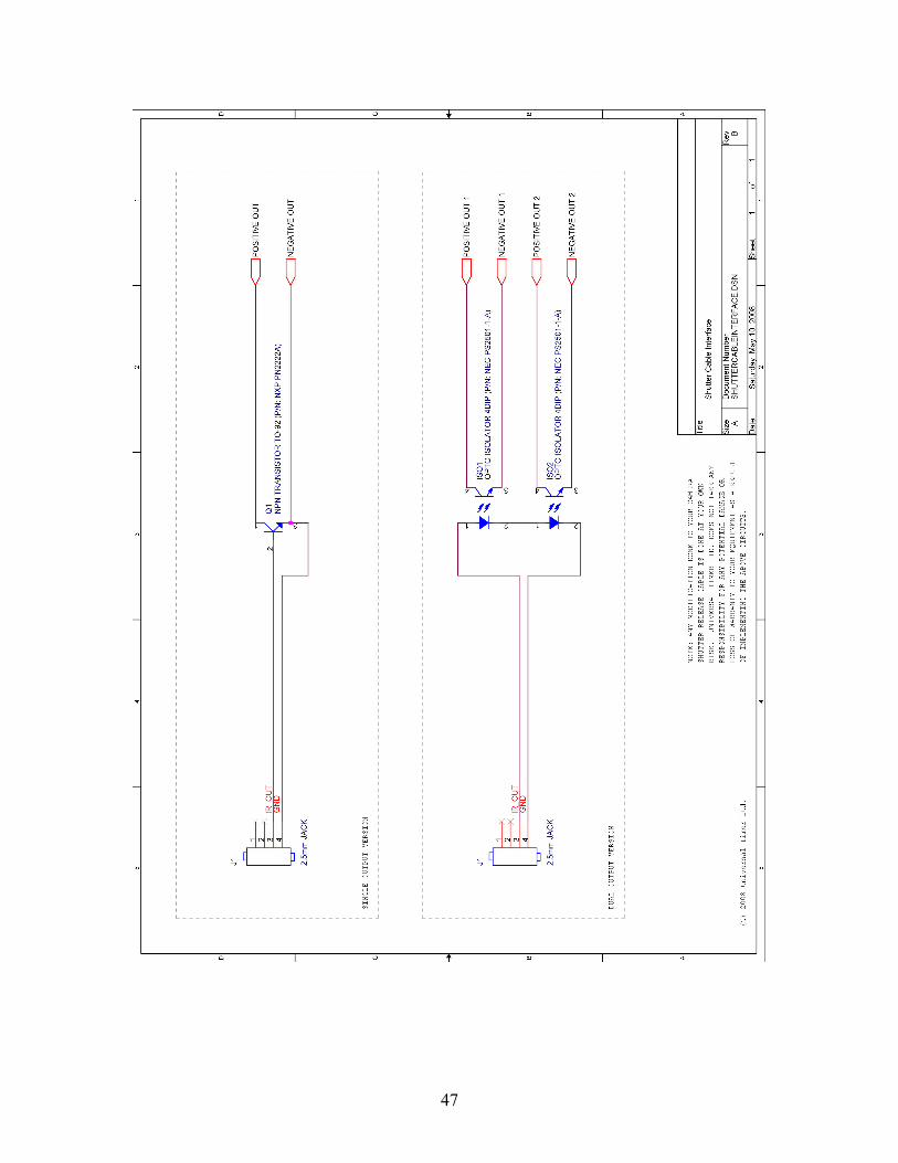
Camera shutter release interface:Camera shutter release interface:Camera shutter release interface:Camera shutter release interface:
If your camera does not support an infra-red remote, you can still connect the Timer to
your camera using a shutter release cable. Below is a simple schematic for building the
interface circuit (for the do-it-yourself users). This schematic will allow you to modify
your shutter release cable so that you can take advantage of many of the Timer
functions. The circuit connects to one of the two Timer sensor connections using a
2.5mm jack. Standard length is 6ft.
A typical shutter release cable contains two switches: the first one wakes-up the camera
(half way press), the second switch activates the shutter. The interface circuit provides a
method for closing the switches in the shutter release cable.
There are two circuits available; you only need to implement one of them:
• In some cameras the shutter is activated when closing the second switch – in this
case implement the simpler SINGLE SWITCH OPTION from the schematic.
• In other cameras, the shutter activates when both switches are closed at the
same time – in this case you will need to use the DUAL SWITCH OPTION from the
schematic.
You need to connect the positive and the negative wires of the shutter release cable to
the POSITIVE and the NEGATIVE outputs of the interface circuit.
Configure the Timer by selecting CABL camera code in Fn-4 camera code selection.
CABL code activates the interface contacts for 0.5sec.
In order to improve the reaction time of your camera, make sure to extend the sleep
time of your camera. By default, the camera will enter a sleep mode after a few seconds
of inactivity.
Please note that this camera interface has some limitations; the camera bulb mode and
FL-2 modes are not supported.
47
48
9. TERMS AND CONDITIONS
Refer to www.universaltimer.com/terms_and_cond.html for full details on terms and
conditions policy.
10. RETURN AND WARRANTY
Refer to www.universaltimer.com/warranty.html for full details on returns and warranty
policy.

49
Copyright Universal Timer Ltd. © 2007, 2008
An electronic version of this manual in PDF format can be downloaded from:
www.universaltimer.com/UPT_UserGuide_RevA2.pdf