pinpoint: an asynchronous time-based location
TRANSCRIPT
PinPoint: An Asynchronous Time-Based LocationDetermination System
Moustafa Youssef∗
Depart. of Computer ScienceUniversity of Maryland
College Park, MD 20740, USA
Adel YoussefDepart. of Computer Science
University of MarylandCollege Park, MD 20740, USA
Chuck RiegerAlphaTrek, Inc.
Ashton, MD 20861, USA
Udaya ShankarDepart. of Computer Science
University of MarylandCollege Park, MD 20740, USA
Ashok AgrawalaDepart. of Computer Science
University of MarylandCollege Park, MD 20740, USA
ABSTRACTThis paper presents the design, implementation and evalu-ation of the PinPoint location determination system. Pin-Point is a distributed algorithm that enables a set of n nodesto determine the RF propagation delays between every pairof nodes, from which the inter-node distances and hence thespatial topology can be readily determined. PinPoint doesnot require any calibration of the area of interest and thusis rapidly deployable. Unlike existing time-of-arrival tech-niques, PinPoint does not require an infrastructure of accu-rate clocks (e.g., GPS) nor does it incur the o(n2) messageexchanges of “echoing” techniques. PinPoint can work withnodes having inexpensive crystal oscillator clocks, and incursa constant number of message exchanges per node to deter-mine the location of n nodes. Each node’s clock is assumedto run reliably but asynchronously with respect to the othernodes, i.e., they can run at slightly different rates becauseof hardware (oscillator) inaccuracies. PinPoint provides amathematical way to compensate for these clock differencesin order to arrive at a very precise timestamp recovery thatin turn leads to a precise distance determination. Moreover,each node is able to determine the clock characteristics ofother nodes in its neighborhood allowing network synchro-nization. We present a prototype implementation for Pin-Point and discusses the practical issues in implementing themathematical framework and how PinPoint handles the dif-ferent sources of error affecting its accuracy. Evaluation ofthe prototype in typical indoor and outdoor environmentsshows that PinPoint gives an average accuracy of four to six
∗Also affiliated with Alexandria University, Egypt.
Permission to make digital or hard copies of all or part of this work forpersonal or classroom use is granted without fee provided that copies arenot made or distributed for profit or commercial advantage and that copiesbear this notice and the full citation on the first page. To copy otherwise, torepublish, to post on servers or to redistribute to lists, requires prior specificpermission and/or a fee.MobiSys’06, June 19–22, 2006, Uppsala, Sweden.Copyright 2006 ACM 1-59593-195-3/06/0006 ...$5.00.
feet, in different environments, allowing PinPoint to supportaccurate rapidly deployable localization scenarios.
Categories and Subject DescriptorsC.3 [Special-Purpose and Application-Based Systems]:Real-time and embedded systems
General TermsAlgorithms, Measurement, Performance, Theory.
KeywordsLocation determination, rapidly deployable location deter-mination, time-of-arrival location determination, ranging tech-niques
1. INTRODUCTIONLocation determination technologies have been an active
research area. Many systems have been developed over theyears based on different technologies including GPS [10],wide-area cellular-based systems [28], infrared-based sys-tems [2, 30], various computer vision systems [16], physi-cal contact systems [21], and radio frequency (RF) basedsystems [3, 15, 17, 23, 34]. These systems provide the tech-nology needed for a wide range of applications. Examples[6, 18] include ubiquitous computing environments, location-based protocol enhancement, and location support for dis-aster management systems.
In this paper, we present the design, implementation andevaluation of the PinPoint1 location determination systemfor ad-hoc networks. PinPoint is a distributed protocol thatruns on all the nodes in the network. It does not require anypre-planing for deployment and thus is suitable for scenariosthat require rapid deployment.
1The PinPoint technology presented here is different fromthe PinPoint technology described in [32]. The differencesbetween the two technologies are discussed in Section 6 onrelated work.
165
PinPoint is a time-of-arrival (ToA) based system whichdepends on measuring the time it takes a signal to reach thereceiver to estimate the distance between the sender andthe receiver. Traditional ToA based systems either requiresynchronized clocks, e.g. the GPS system [10], or uses the“echoing” method, e.g. [32, 22], where a node measures theroundtrip time of a signal transmitted to a remote node toestimate the distance to this node. Systems that require syn-chronized clocks are expensive to implement while systemsbased on the ”echoing” method require o(n2) message ex-changes to estimate the location of n nodes (o(n) per node)and suffer from more variance in the time measurement dueto the echoing requirement. PinPoint does not require syn-chronized clocks and requires o(n) message exchanges to lo-cate n nodes (o(1) messages per node) while using one-waymessages only.
Central to the PinPoint idea is the notion of sending andreceiving a “timestamp” between two mobile units. Eachunit is assumed to have its own clock, which runs reliablybut asynchronously with respect to the other units, i.e.,the clocks’ current “time of day” might be considerably dif-ferent, and they might run at slightly different rates becauseof hardware (oscillator) inaccuracies. PinPoint provides amathematical way to compensate for these clock differencesin order to arrive at a very precise timestamp recovery thatin turn leads to a precise distance determination. Moreover,each node is able to determine the clock characteristics ofother nodes in its neighborhood allowing network synchro-nization.
PinPoint works in two steps. In the first step (ranging),each node estimates the distances to all the other nodesin its neighborhood. In the second step (range combining),the nodes use the distance estimates to estimate the networktopology. In this paper we focus on the ranging problemas it is the more challenging one. We briefly discuss howPinPoint performs range combining in Section 3.
PinPoint has the following features:
• No time synchronization is required between nodes inPinPoint. Nodes measure the transmission and recep-tion time of a signal based on their local clock.
• PinPoint does not require any infrastructure supportor pre-planning for the area of deployment. There-fore, it is well suited for scenarios that require rapiddeployment.
• PinPoint has low computation cost. The algorithmused is based on simple algebraic operations on scalarvalues. Moreover, it requires o(1) number of messagesper node to locate n nodes.
• PinPoint is independent of the communication technol-ogy used between the nodes. For example, it can beused with the narrow-band RF, spread spectrum [29],or ultra wideband technologies [31]. In this paper, wepresent a prototype implementation of PinPoint usingthe spread spectrum technology (compatible with the802.11 standard [29]).
The rest of the paper is organized as follows: In Section 2we present the basic idea behind PinPoint, the mathemat-ical framework it uses to obtain the distance estimate, andthe different sources of error affecting PinPoint accuracy.Section 3 describes the PinPoint node architecture and the
Global Timet Node A Node B
t1
t1+d
t2
t2+d
t3
t3+d
t4
t4+d
1aτ
2aτ
3aτ
4aτ
1bτ
2bτ
3bτ
4bτ
)1,( aA τ
)2,( bB τ
)3,( aA τ
)4,( bB τ
First Cycle
Second C
ycle
Arbitrary length
Arbitrary length
Arbitrary length
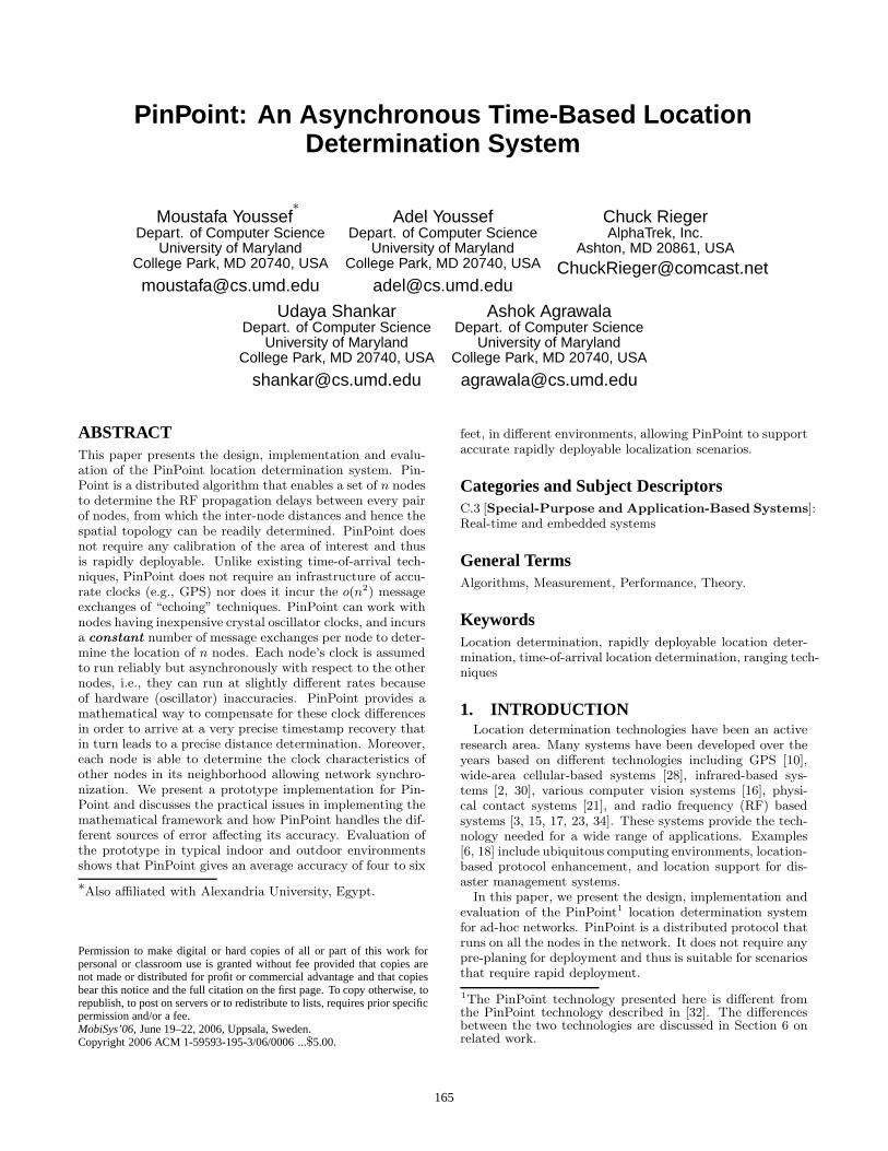
Figure 1: The PinPoint measurement phase. Thephase contains two cycles with n (number of nodes)turns per cycle. Note that all messages are one-waymessages and all times are measured by local clocks.
PinPoint protocol. We present our prototype implementa-tion of PinPoint in Section 4. Section 5 presents PinPointevaluation based on the developed prototype. In Section 6we discuss the related work. Finally, sections 7 and 8 discussdifferent aspects of the system and conclude the paper.
2. PINPOINT FUNDAMENTALS
2.1 IntroductionThe goal of PinPoint is to be able to determine the rela-
tive positions of nodes, possibly mobile, in 3D. This sectiondescribes how two units, say A and B, in a set of units par-ticipating in the PinPoint protocol obtain the distance be-tween them. The general protocol between a set of n nodesis described in Section 3.4.
Basic PinPoint operation (Figure 1) calls for one unit (unitA) to broadcast a signal to all other nodes (here unit B).As A sends the signal, it captures the transmit timestamp.B receives this signal, and captures the receive timestamp.The units then swap roles, wherein unit B broadcasts atimestamp signal with B capturing its transmit timestampand A capturing its receive timestamp. These exchanges arerepeated twice. Finally, the units swap information aboutall sent and received timestamps with each other so thatboth sides know the eight timestamp values.
After this exchange each unit has enough information, asexplained in the rest of the section, to eliminate the basicdifference in the two units’ clock readings, and hence to de-
166

termine the time of flight of the signal between the two units.Once the time of flight is known, the physical distance be-tween the two units is known, because of the constant natureof the speed of light (and radio waves). In addition, eachnode also determines the clock characteristics (drift and off-set relative to itself) of the nodes in its neighborhood. In therest of this section, we give the mathematical formulation ofPinPoint.
2.2 NotationAs a notational convention, we will always use τ to denote
local clock times, and t to denote global clock times. Also,when discussing local clock times, the letter contained inthe subscript on the τ will always indicate the clock whichrecords the time, so for example τa1 is a time recorded bythe local clock at node A. We refer to the clock offset anddrift rate of a node as α and β respectively.
Throughout, we use time equivalent of distance, i.e., werepresent a distance d by the time it will take light to travelthat distance. In the environments we expect this technol-ogy to be used, the speed of light does not vary significantly,thus making this measure of distance stable.
2.3 Mathematical FormulationWithout loss of generality, we fix on any two nodes, A
and B, in the network, and assume that they are neighbors.We describe the messages that they expect to receive fromeach other and the processing involved in estimating thelocation. The same discussion holds for the case of n nodesas discussed in Section 3.4. Both nodes A and B have localclocks, which may have some drift and offset, and for globaltime t, their clock readings are respectively
τa = βa(αa + t)
τb = βb(αb + t) (1)
Figure 1 shows the messages exchanged and the timing ina measurement cycle. Now, at time t1 node A broadcasts atuple giving its identity and a timestamp, the latter denotedby τa1. That is,
τa1 ≡ τa(t1) = βa(αa + t1) (2)
and the tuple broadcast is (A, τa1). Node B receives it andrecords the time of receipt as τb1. If we denote the timedistance between A and B as d, then the (global) time atwhich B should receive the broadcast from A is t1 + d, sothat
τb1 = βb(αb + t1 + d) (3)
Since each node is running the same decentralized proto-col, B also sends a two-tuple, say at global time t2. In stepssimilar to above, B broadcasts the tuple (B, τb2), where
τb2 ≡ τb(t2) = βb(αb + t2) (4)
and A receives this broadcast at global time t2 + d, which Abelieves is time
τa2 = βa(αa + t2 + d) (5)
Once this first round of messages has completed, they bothsend a second round, say with A sending its second messageat time t3, and B sending its message at time t4. Using nota-tion similar to before, we thus have τa3 = βa(αa + t3), τb3 =βb(αb + t3 + d), τb4 = βb(αb + t4), and τa4 = βa(αa + t4 + d).
Collecting all eight of these together in one place for ref-erence (we refer to these as “the reference equations”), wehave:
τa1 = βa(αa + t1) τb1 = βb(αb + t1 + d)τa2 = βa(αa + t2 + d) τb2 = βb(αb + t2)τa3 = βa(αa + t3) τb3 = βb(αb + t3 + d)τa4 = βa(αa + t4 + d) τb4 = βb(αb + t4)
(6)
Now that both rounds of messages are complete, the nodesenter the information exchange portion of the algorithm,with A sending the values τa2 and τa4 to B, and B sendingthe values τb1 and τb3 to A. At this point, both of the nodesknow all eight values τa1, τa2, τa3, τa4, τb1, τb2, τb3, and τb4.
The nodes use these values to independently compute theratio βa/βb. To see how this is done, note that
τa3 − τa1
τb3 − τb1=
βa(αa + t3) − βa(αa + t1)
βb(αb + t3 + d) − βb(αb + t1 + d)=
βa
βb(7)
The next series of steps is designed to allow for the cal-culation of the values βad and βbd. The reasons for this aretwofold. First, both βa and βb are typically close to one,so the quantities βad and βbd are both good estimates of d.Second, both quantities are valuable for helping synchronizethe clocks in the network.
We show here how to determine βbd. The developmentfor βad is similar. First, consider the quantities Δ1 and Δ2
given by
Δ1 ≡ τb1 − τa1 = βb(αb + t1 + d) − βa(αa + t1) (8)
and
Δ2 ≡ τa2 − τb2 = βa(αa + t2 + d) − βb(αb + t2) (9)
Averaging these two quantities gives
Δ1 + Δ2
2=
1
2[βb(αb + t1 + d) − βa(αa + t1)
+βa(αa + t2 + d) − βb(αb + t2)]
=βa + βb
2d +
t2 − t12
(βa − βb) (10)
Now, from the first and second lines of the reference equa-tions (6), we have
τa2 − τa1 = βa(t2 − t1) + βad (11)
or equivalently that
t2 − t1 =τa2 − τa1
βa− d (12)
Substituting Equation 12 into Equation 10 gives
Δ1 + Δ2
2=
βa + βb
2d +
βa − βb
2(τa2 − τa1
βa− d)
= βbd +1
2(1 − βb
βa)(τa2 − τa1) (13)
or equivalently
βbd =Δ1 + Δ2
2+
1
2(βb
βa− 1)(τa2 − τa1) (14)
Note that every quantity on the right side of Equation 14is computable by every node, as long as they have the eightquantities on the left sides of the reference equations. Note
167

further that determining βbd gives us βad, since βad =(βaβb
)(βbd), and the nodes know both right hand side quan-
tities.
2.4 DiscussionAll the message exchanges in the PinPoint protocol are
one-way and timestamped by the local clocks. PinPointmakes use of the broadcast medium to achieve its o(n) one-way message exchanges (Section 3.4). Note that although“echoing” based systems, e.g. [32, 22], may have a broad-cast medium, these systems cannot benefit from it as a nodemust unicast each message to one of the nodes and wait forthe echo message from this node to estimate the round triptime, given a total of o(n2) message exchanges.
2.5 Sources of ErrorThere are three main sources of errors in PinPoint: the
built-in hardware delay, multipath effect, and the non-line-of-sight (NLOS) transmission.
The built-in hardware delay refers to the delay of the dif-ferent components of PinPoint hardware before the times-tamping process. Usually, this delay is constant or exhibitssmall variations. The architecture of the PinPoint unit (asdiscussed in Section 3) permits it to be self-calibrating: APinPoint node could periodically send and timestamp a cal-ibration sequence to itself to adjust its own zero reference(i.e. the node will act as both the sender and the receiverof the PinPoint messages).
Multipath refers to the fact that a signal transmitted fromthe sender may reach the receiver through different paths.Since each path can have a different length, different signalsmay arrive at different times at the receiver antenna. Thereare two important characteristics for multipath propagation[24]. The direct (LOS) signal will always reach the receiversbefore the other multipath components. Second, multipathcomponents will normally be weaker than the LOS compo-nent. PinPoint mitigates the effect of multipath by basingits calculation on the first and longest chain of received base-band signals (as discussed in Section 4). This correspondsmost of the time to the LOS component based on the abovetwo characteristics.
NLOS transmission exists when the LOS component isblocked due to the presence of RF-opaque objects. In thiscase, the receiver timestamp is based on a NLOS signaland hence overestimates the true distance. PinPoint mit-igates the NLOS effect in its range-combining phase wherethe estimated distances are used to estimate the locations ofthe nodes. In this phase, the redundant distance informa-tion and estimated distances from other nodes (where LOSpropagation is dominant) can help detect the outliers (thosebased on NLOS measurements) and reduce the overall er-ror. Moreover, since PinPoint is independent of the commu-nication technology, a communication technology (and/or atransmission frequency) can be used to reduce the probabil-ity of NLOS propagation2.
In Section 5 we present the performance evaluation of aPinPoint prototype in typical indoor and outdoor environ-ments that shows the stable PinPoint performance underthese sources of error.
2UWB [31, 9] is a technology that can be used for this pur-pose.
ClockModule
Communication Module
ComputationModule
Figure 2: PinPoint node architecture. Each nodeconsists of three modules: a clock module, a com-munication module, and a computation module, allinterconnected by a bus.
3. PINPOINT NODE ARCHITECTURE ANDPROTOCOL
Each PinPoint node consists of three modules: a clockmodule, a communication module, and a computation mod-ule, all interconnected by a bus (Figure 2). The modulesand the bus are realizable from off-the-shelf hardware com-ponents as described in Section 4.
3.1 Clock ModuleThe clock module has a time-of-day clock whose offset and
drift are assumed to be essentially constant over a few tensof milliseconds. High clock drifts, of the order of 100 partsper million (ppm), are perfectly acceptable. Thus PinPointnodes can utilize inexpensive crystal oscillators to imple-ment their clocks. The clock module also has a countdowntimer, driven by the time-of-day clock, and registers for stor-ing clock values at certain communication events.
3.2 Communication ModuleThe communication module has transmit and receive mes-
sage buffers, the modulation and demodulation units, andthe antenna. PinPoint technology requires only half-duplexoperation.
The communication module and clock module are linkedtogether so that the receive and transmit times of messagescan be recorded. The transmit time of a message is the valueof the transmitting node’s time-of-day clock when a specifiedbit is transmitted. The receive timestamp of a message at anode is the value of the receiving node’s time-of-day clock atthe arrival of the specified bit. The required interconnectionbetween the communication and clock modules to achievethis is implementable with nominal hardware.
3.3 Computation ModuleThe computation module consists of a general purpose
computation and storage engine. It manages the clock andcommunication modules and carries out the operations ofthe PinPoint protocol described in the next section.
3.4 PinPoint ProtocolThe PinPoint protocol is the protocol governing the ex-
change of messages, the measurement of send and receive
168

times, the dissemination of this measurements to all nodes,and the calculation of the spatial locations and clock at-tributes of all nodes. We assume that all nodes are withinthe listening range of one another. We discuss the generalcase of large networks in Section 7.
The protocol operation consists of three phases: measure-ment phase, information exchange phase, and computationphase.
3.4.1 Measurement PhaseA measurement phase consists of two measurement cycles.
In each cycle, each node broadcasts (in its turn) a messagecontaining its ID and the transmit timestamp of the mes-sage, and records the receive timestamp of the messagesbroadcast by other nodes (as described in Section 2.3). Fora network of n nodes, each node takes a turn for a total of nturns per cycle (2n turns in the entire measurement phase)3. For example, in Figure 1, there are two turns per cyclecorresponding to the two nodes. We assume that units willremain stationary during the PinPoint message exchangephase 4.
3.4.2 Information Exchange PhaseIn this phase, each node broadcasts a message contain-
ing its receive timestamp for messages transmitted by othernodes in a measurement phase. For a network of n nodes,we have n turns in the information exchange phase.
3.4.3 Range Combining PhaseAfter the Information Exchange phase, each node has
enough information to compute an estimate of the distance(range) to all nodes within its listening range, as describedin the Section 2.3. The goal of the range-combining phaseis to obtain the topology of the network using the estimateddistances. Each PinPoint node uses a technique similar tothe self-positioning algorithm (SPA) described in [5]. Weassume that this algorithm will run only once. That is,once a local topology is determined, nodes entering or leav-ing are added or removed incrementally. No communicationtakes place during this phase. Therefore the total numberof messages exchanged in the entire network is 3n which isa constant number of message exchanges per node.
4. PINPOINT IMPLEMENTATIONThis section describes the current implementation of Pin-
Point5. We refer to this prototype as PP2. Figure 3 showsthe current prototype.
4.1 PinPoint HardwareThe current PinPoint implementation is based on the fol-
lowing main hardware components:
• Altera Cyclone 1C20 FPGA development kit
• Maxim 2820 radio with Maxim 2242 RF power amp
3We discuss the contention resolution between nodes in Sec-tion 7.5.4This is a reasonable assumption considering the length ofthe message exchange phase.5We chose to build our own hardware out of off-the-shelfcomponents to have full control over the different compo-nents of the system. This helped in reducing the variabilityin the system.
Figure 3: PinPoint prototype (PP2). The prototypeis based on an Altera Cyclone 1C20 FPGA devel-opment kit, a Maxim 2820 radio, and MaxStream9xStream radio modem.
• MaxStream 9xStream radio modem
The Altera Cyclone 1C20 FPGA provides the computa-tion processor and the timestamping clock while the Maxim2820 and Maxstream radio provide the communication mod-ules needed for transmitting the signal used for timestamp-ing and transferring the PinPoint protocol messages respec-tively. The rest of the section gives an overview about eachof these components.
4.1.1 Altera Cyclone 1C20 FPGA development kitThe Cyclone 1C20 FPGA (field programmable gate array)
from Altera has a phase lock loop (PLL) capable of runningat clock rates up to 300 MHz, which we use as the PP2’smain timestamping clock (giving around 3 ns accuracy).
4.1.2 Maxim 2820 radio with Maxim 2242 RF poweramp
The MAX2820 is a 2.4 GHz radio chip intended for 802.11band similar applications. The chip can cover distances of upto several hundred feet - compatible with PinPoint’s oper-ating range goals. The chip is needed for transmitting thesignal used for timestamping.
169

Note that PinPoint design can be integrated with the cur-rent 802.11 based cards alleviating the need for the MAX2820module.
4.1.3 MaxStream 9xStream radio modemPinPoint’s conceptual design requires that the PP2 units
be able to exchange high-level information about timestampsafter generating and acquiring those timestamps via a lower-level protocol (described in the next section). Although theMAX2820 radio chip would serve for both the high- and low-level protocols, the PP2 design implements these two pro-tocols via two separate radio technologies: the MAX2820radio chip for the low-level protocol, and a radio modemunit, the MaxStream 9xStream for the high-level protocol.The rationale behind this separation was simply to limitPP2 development time and cost, since the MAX2820 evalu-ation kit does not include the required hardware or softwareto implement a high-level data exchange protocol.
The MaxStream 9xStream unit offers a simple, UART-likedata transport protocol using 900 MHz FM radio technol-ogy, which is capable of sending and receiving ASCII datastreams over distances well in excess of PinPoint’s require-ments. The 9xStream performs error checking and correc-tion, and is thus considered to be a completely reliable wire-less data transport channel.
We want to emphasize two points here:
• PinPoint is independent of the technology used fordata transmission. In the current prototype, data trans-fer occurs over 900 MHz FM radio technology.
• If PinPoint technology is integrated with an 802.11based card, this module will not be needed as thetimestamp information can be piggy-backed on 802.11frames.
4.1.4 TimestampingDue to noise, signal reflections, and other factors, we use
a repetitive pattern of baseband pulses rather than a sin-gle signaling event to obtain a robust signaling technique.Having a repetitive stream of events allows the receiver tomiss some or even most of them, yet still be able to identifymoments in time that were also known to the transmit side.
After a variety of experiments, the following timestampsignaling protocol was selected (Figure 4):
• Send 20, 128 μs, baseband cycles.
• Send one baseband cycle with its 64 μs low half filledwith 18 ”dense pulses”, each of cycle time approxi-mately 3.2 μs
• Send an additional 20 baseband cycles.
By convention, the receiver identifies the ”official” times-tamp as the last rising baseband edge prior to the densepulses. Since each baseband cycle takes 128 μs, this 41-cyclebroadcast lasts just over 5 milliseconds (ms), fast enough inprinciple to be repeated many times per second.
4.1.5 Power RequirementsCurrently, each PinPoint unit uses 18 rechargeable NiCad
batteries (each 2000 ma-hour, 1.2 volts). Ten of them formthe positive voltage source of nominally +12 volt. A +5volt regulator shifts some of this unregulated supply down
0 1 19 20 21 22 40
41 baseband cycles(128 us each)
Official timestamp
18 dense pulses(3.2 us each)
Figure 4: Timestamp timing sequence. The receiveridentifies the ”official” timestamp as the last risingbaseband edge prior to the dense pulses.
to drive several components needing regulated +5 volts, andthe rest goes to the Altera and radio boards, which havetheir own regulators onboard. The other eight batteries formthe negative supply branch, nominally -9.6 volts, which isonly used by several line drivers on the radio board.
Note that for future versions of PinPoint, integrated withwireless cards, PinPoint can be powered from the card’s sup-ply without requiring external power source.
4.2 PinPoint Software
4.2.1 PinPoint Operating SystemThe Altera FPGA development system includes a full C
software development environment that is capable of compil-ing, then downloading and running ANSI standard C codeon the Altera CPU (via the UART contained in the Alterareference design). This is the software development environ-ment employed to develop the PinPoint operating system,PP2.C.
4.2.2 PinPoint Protocol ImplementationThe current implementation of the PinPoint protocol is
based on polling. We chose this protocol for its simplicityand we discuss other alternatives in Section 7. For a set ofn nodes, one of them is a master node that polls the othern−1 nodes in turn. When the master polls a node, this nodeperforms its turn of the protocol as explained in Section 3.Changing any of the nodes parameters is performed at anytime through connecting the unit to the PC through theUART interface.
5. SYSTEM EVALUATIONWe conducted several experiments to investigate the per-
formance of PinPoint. In the first experiment, we examinehow well PinPoint captures the relation between distanceand time and how consistent the measurements are. Thesecond set of experiments aims at studying the performanceof PinPoint in indoor and outdoor environments for staticunits. The third set of experiments examines the perfor-mance of PinPoint when the unit is mobile.
In all experiments, we used two PP2 units. We call themthe “log unit” and the “test unit”. We connected the log unitto the PC in all experiments and logged all events and datarelated to the PinPoint protocol operation. The test unitwas freely moving and we changed its location to evaluatedifferent aspects of the PinPoint prototype. We start bypresenting the system parameters.
170
50
55
60
65
70
75
0 5 10 15 20 25 30 35
Clo
ck T
icks
Distance (foot)
MeasuredPerfect
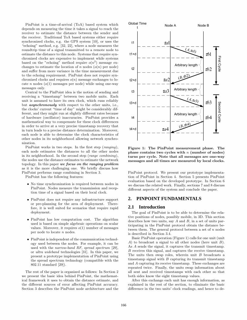
Figure 5: Relation between distance and the re-ported clock ticks. The error bars represent onestandard deviation.
0 0.05
0.1 0.15
0.2 0.25
0.3 0.35
0.4 0.45
46 48 50 52 54 56 58 60
Pro
babi
lity
Clock Ticks
(a) 2 feet
0 0.05
0.1 0.15
0.2 0.25
0.3
48 52 56 60 64 68
Pro
babi
lity
Clock Ticks
(b) 20 feet
0
0.05
0.1
0.15
0.2
0.25
54 60 66 72 78 84 90
Pro
babi
lity
Clock Ticks
(c) 35 feet
Figure 6: Clock ticks histogram for different dis-tances.
5.1 System ParametersAs we pointed out in Section 4, the PP2 prototype uses a
300 MHz clock for timestamping. This means that each tickis 3.33 nanoseconds, and since light travels approximately11.8 inches in one nanosecond, then each tick of the times-tamp clock equates to approximately 3.28 feet of distance.
We calibrated the units by putting the test unit adjacentto the log unit. We measured a clock reading of 52 forthis zero-distance configuration. This reading correspondsto the system overhead (built-in hardware delay). We sub-tract this offset from all of our calculations to get the timeequivalent of distance. Multiplying this time by 3.28 givesthe estimated distance in feet.
5.2 Basic Protocol PerformanceFigure 5 shows the clock ticks reported by PinPoint when
the test unit moves away from the log unit. We can seefrom the figure that as expected, as the distance increases,
the number of clock ticks the signal takes to travel betweenthe two units increases. The relation, however, is not aperfect straight line due to the error in measurements. Wewill discuss the error in PinPoint measurements in the nextsection.
Figure 6 shows the reported clock ticks histogram corre-sponding to the three distances in Figure 5. The varianceof clock ticks histogram increases as the distance increases.The reason is that for larger distances, the transmitted sig-nal becomes weaker and the signal to noise ratio decreasesso that some erroneous dense edges may be detected incor-rectly affecting the accuracy of the measured time.
5.3 Static PerformanceWe used two testbeds to evaluate the performance of Pin-
Point: an indoor testbed and an outdoor testbed.
5.3.1 Indoor testbedWe performed two indoor experiments. The first exper-
iment was conducted in a basement of an area of approxi-mately 1450 square feet (Figure 7). The basement is dividedinto three areas: the workshop, the pool table area, and therecreation area. The basement environment presents a chal-lenging indoor environment as it has cabinets, book shelves,metallic objects, electronic devices, etc. For this testbed,the mobile unit was placed at eight different locations (bothLOS and NLOS) in the basement and we recorded the clockreadings. Figure 8 shows the actual and measured distancesfor the different test locations. We can see from Figure 8and the derived summary in Table 1 that PinPoint has anaverage accuracy of 4.18 feet (4.4 standard deviation) andworst case error of 14.2 feet (Location 7) in this complexindoor environment. We believe that the performance atLocation 7 is due to the severe multipath environment atthat location.
Our second indoor testbed covered a multi-floor testbedand there were no direct LOS between the mobile unit andthe log unit at all the 17 locations. Figure 9 shows the re-sults. We can see from the figure that PinPoint maintainsits performance even with no LOS between units. This con-firms our discussion in Section 2.5. We also note from thetable that the maximum error in the first experiment (atLocation 7) is more than that of the second experiment (atLocation 14). We believe that this is because the basementprovides more opportunity for multipath effects than any ofthe 17 NLOS test locations.
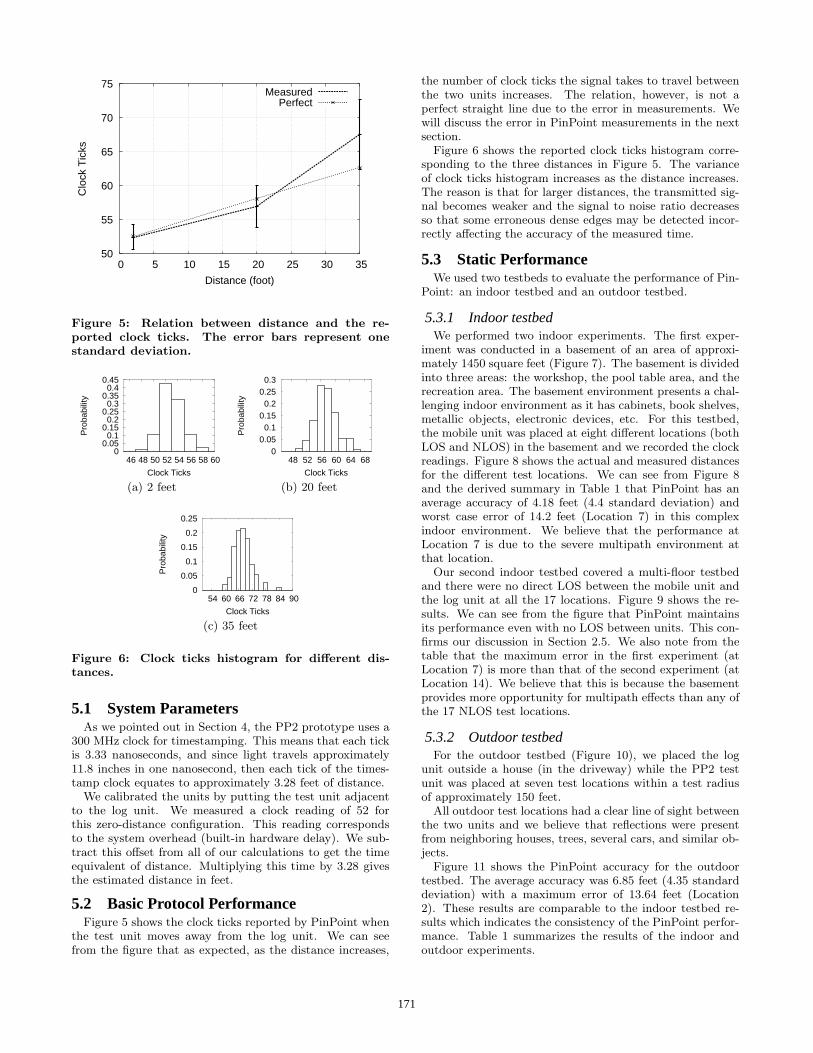
5.3.2 Outdoor testbedFor the outdoor testbed (Figure 10), we placed the log
unit outside a house (in the driveway) while the PP2 testunit was placed at seven test locations within a test radiusof approximately 150 feet.
All outdoor test locations had a clear line of sight betweenthe two units and we believe that reflections were presentfrom neighboring houses, trees, several cars, and similar ob-jects.
Figure 11 shows the PinPoint accuracy for the outdoortestbed. The average accuracy was 6.85 feet (4.35 standarddeviation) with a maximum error of 13.64 feet (Location2). These results are comparable to the indoor testbed re-sults which indicates the consistency of the PinPoint perfor-mance. Table 1 summarizes the results of the indoor andoutdoor experiments.
171

������������
������
������
��������
���������
���������
������������
���������
���������
��������
��������
������
������
Test Location
���������
���������
������������
����������������������������������
BathHalf wall
Stairs
Workshop
Closet
Recreation Area
Poo
l Tab
le
427’
15’
19’
43’
Log Unit
1
2
3
5
6
7
8
Log Unit
Figure 7: The layout of the indoor testbed (not toscale).
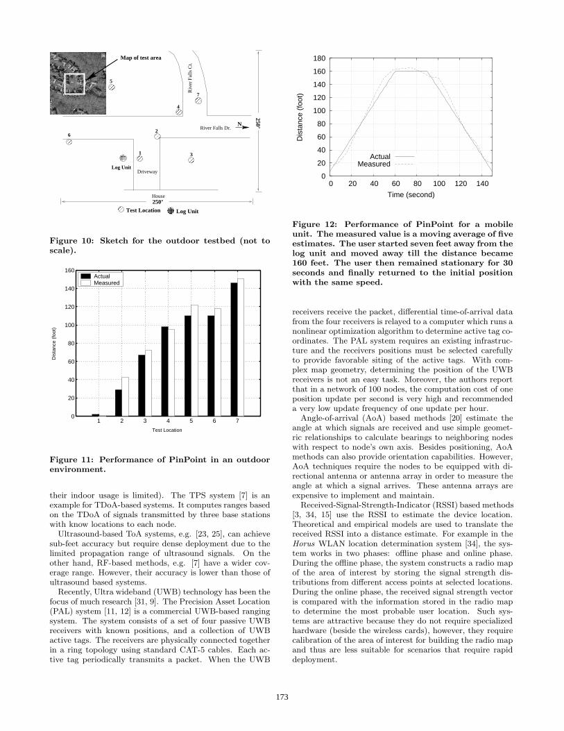
5.4 Mobile PerformanceFor this experiment, we moved the test unit with a con-
stant speed emulating the typical user speed (about 2.5 feetper second). The user started seven feet away from the logunit and moved away till the distance became 160 feet. Theuser then remained stationary for 30 seconds (to see howfast the system stabilizes) and finally returned to the initialposition with the same speed. Figure 12 shows the results.We can see from the figure that PinPoint can track the userin realtime. The reason is that the PinPoint exchange cycleis much faster than the user mobility rate.
6. RELATED WORKNode localization has been the topic of active research and
many systems have made their appearance in the past fewyears. The majority of existing localization systems consistsof two basic phases: (1) ranging and (2) range combining.Ranging is the process of estimating node-to-node distancesor angles. Range combining is the process of estimatingnode position using the estimated ranges.
In the rest of the section, we describe the different tech-niques for range estimation and range combining and howPinPoint relates to them. We do not explicitly differenti-ate between infrastructure based systems and ad hoc basedsystems as the focus of the paper is on the ranging part ofPinPoint. We compare PinPoint to other location determi-nation systems in Table 2.
6.1 Ranging MethodsThe most popular ranging methods are: time-based meth-
ods, angle-of-arrival based methods, received signal strengthbased methods, and network connectivity based methods.
Time-based methods, like Time-of-Arrival (ToA) or Time-Difference-of-Arrival (TDoA), record the signal transmissiontime and the signal arrival time or the difference of arrivaltimes. The propagation time can be directly translatedinto distance, based on the known signal propagation speed.These methods can be applied to different types of signals,
1 2 3 4 5 6 7 80
5
10
15
20
25
30
35
40
45
50
Test Location
Dis
tanc
e (f
oot)
ActualMeasured
Figure 8: Performance of PinPoint in the first in-door testbed. The mobile unit had LOS and NLOSpath to the log point at different locations.
1 2 3 4 5 6 7 8 9 10 11 12 13 14 15 16 170
10
20
30
40
50
60
70
80
Test Location
Dis
tanc
e (f
oot)
ActualMeasured
Figure 9: Performance of PinPoint in the secondindoor testbed. The mobile unit did not have LOSto the log point at any location.
such as RF and ultrasound. Traditional ToA based systemseither require synchronized clocks, e.g. the GPS system [10],or uses the “echoing” method, e.g. [32, 22], where a nodemeasures the roundtrip time of a signal transmitted to a re-mote node to estimate the distance to this node. Systemsthat require synchronized clocks are expensive to implementwhile systems based on the “echoing” method require o(n2)message exchanges to estimate the location of n nodes andsuffer from more variance in the time measurement due tothe echoing requirement.
The GPS system [10] is a widely used outdoor ToA-basedsystem. The system is based on measuring the ToA of thesignals transmitted from synchronized satellites. However,GPS receivers require a LoS to the satellite (and therefore
172
Driveway
House
���������
���������
���� Test Location Log Unit
���������
���������
���������
���������
��
��
����
����
����
����
N
Map of test area
250’
250’
River Falls Dr.
Log Unit
Riv
er F
alls
Ct.
4
7
5
1
2
3
6
Figure 10: Sketch for the outdoor testbed (not toscale).
1 2 3 4 5 6 70
20
40
60
80
100
120
140
160
Test Location
Dis
tanc
e (f
oot)
ActualMeasured
Figure 11: Performance of PinPoint in an outdoorenvironment.
their indoor usage is limited). The TPS system [7] is anexample for TDoA-based systems. It computes ranges basedon the TDoA of signals transmitted by three base stationswith know locations to each node.
Ultrasound-based ToA systems, e.g. [23, 25], can achievesub-feet accuracy but require dense deployment due to thelimited propagation range of ultrasound signals. On theother hand, RF-based methods, e.g. [7] have a wider cov-erage range. However, their accuracy is lower than those ofultrasound based systems.
Recently, Ultra wideband (UWB) technology has been thefocus of much research [31, 9]. The Precision Asset Location(PAL) system [11, 12] is a commercial UWB-based rangingsystem. The system consists of a set of four passive UWBreceivers with known positions, and a collection of UWBactive tags. The receivers are physically connected togetherin a ring topology using standard CAT-5 cables. Each ac-tive tag periodically transmits a packet. When the UWB
0
20
40
60
80
100
120
140
160
180
0 20 40 60 80 100 120 140
Dis
tanc
e (f
oot)
Time (second)
ActualMeasured
Figure 12: Performance of PinPoint for a mobileunit. The measured value is a moving average of fiveestimates. The user started seven feet away from thelog unit and moved away till the distance became160 feet. The user then remained stationary for 30seconds and finally returned to the initial positionwith the same speed.
receivers receive the packet, differential time-of-arrival datafrom the four receivers is relayed to a computer which runs anonlinear optimization algorithm to determine active tag co-ordinates. The PAL system requires an existing infrastruc-ture and the receivers positions must be selected carefullyto provide favorable siting of the active tags. With com-plex map geometry, determining the position of the UWBreceivers is not an easy task. Moreover, the authors reportthat in a network of 100 nodes, the computation cost of oneposition update per second is very high and recommendeda very low update frequency of one update per hour.
Angle-of-arrival (AoA) based methods [20] estimate theangle at which signals are received and use simple geomet-ric relationships to calculate bearings to neighboring nodeswith respect to node’s own axis. Besides positioning, AoAmethods can also provide orientation capabilities. However,AoA techniques require the nodes to be equipped with di-rectional antenna or antenna array in order to measure theangle at which a signal arrives. These antenna arrays areexpensive to implement and maintain.
Received-Signal-Strength-Indicator (RSSI) based methods[3, 34, 15] use the RSSI to estimate the device location.Theoretical and empirical models are used to translate thereceived RSSI into a distance estimate. For example in theHorus WLAN location determination system [34], the sys-tem works in two phases: offline phase and online phase.During the offline phase, the system constructs a radio mapof the area of interest by storing the signal strength dis-tributions from different access points at selected locations.During the online phase, the received signal strength vectoris compared with the information stored in the radio mapto determine the most probable user location. Such sys-tems are attractive because they do not require specializedhardware (beside the wireless cards), however, they requirecalibration of the area of interest for building the radio mapand thus are less suitable for scenarios that require rapiddeployment.
173

Table 1: Testbeds’ performance summary (all unitsin foot)
Indoor Indoor NLOS OutdoorRange Tested 37 74 146Average Error 4.18 4.95 6.85Standard deviation 4.44 4.19 4.3595% Error 8.42 11 13.03Maximum Error 14.2 12.75 13.64
Network connectivity based methods, e.g. [13] can be usedfor range estimation if the cost of range estimation hardwareis expensive or if a sensor cannot receive signals from enoughbase stations. For example, the number of hops between twonodes can be used as an estimate of the range between thesetwo nodes as in [19].
6.2 Range/Angle Combining MethodsRange combining is the process of estimating node posi-
tion using the estimated node-to-node ranges. Trilateration,triangulation, multilateration, and landmark-proximity arethe most known techniques for combining ranges.
Trilateration, e.g. as in [7, 19], locates a node by calcu-lating the intersection of three circles. If the ranges containerror, the intersection of the three circles may not be a singlepoint. Triangulation, e.g. as in [20], is used when the angleof the node instead of the distance is estimated, as in AoAmethods. The node positions are calculated in this case byusing trigonometric relationships. In this case, at least twoangles are required. In multilateration, e.g. [26, 8, 14], theposition is estimated from distances to three or more knownnodes by minimizing the error between estimated positionand actual position.
Proximity-based techniques are usually used when no rangeinformation is available. For example, the GPS-less system[4] employs a grid of beacon nodes with known locations;each unknown node sets its position to the centroid of thebeacon locations it is connected to.
The PinPoint localization system belongs to the class oftime-based methods. Compared to the other systems, e.g.the GPS system, it does not require any time synchroniza-tion between the nodes. The PinPoint technology explic-itly handles the clock characteristics of different nodes andhence is able to achieve better accuracy. Moreover, it is afully ad-hoc system with distributed localization algorithmsrunning at every node. It does not require the nodes to beaware of their locations. From a power awareness perspec-tive, all nodes transmit the same number of messages duringthe localization phase resulting in an even distribution ofpower consumption among the nodes. In summary, the Pin-Point localization system provides fine-grained localizationwith an accuracy of few feet without requiring infrastructuresupport and with a wider coverage area. Table 2 comparesPinPoint to other location determination technologies.
7. DISCUSSIONThe current PP2 prototype proved that PinPoint is a
promising technology that provides good accuracy withoutrequiring any pre-planning for the area of interest. In thissection, we discuss various aspects of the PinPoint designand implementation along with ongoing work to enhancethe prototype.
7.1 Accuracy with Clock RateThe current prototype achieves an average accuracy of
four to six feet with a clock rate of 300MHz. Since thedistance error is linear with respect to the accuracy of theclock, we expect that as the clock rate increases the averageaccuracy will increase.
7.2 ScalabilityIn the current prototype, we assume that all nodes are
within the listening range of one another. For large net-works, this may not be true. To solve this problem, clus-tering algorithms [33] can be used to split the network intosubnetworks. The nodes within each subnetwork run thePinPoint protocol to calculate the local topology. Finallythe subnetworks are merged, as needed, to obtain the globalnetwork topology.
7.3 Integration with the Current Wireless Stan-dards
The hardware requirements of PinPoint are minimal andalready exist in many of the current wireless standards.For example, PinPoint can be implemented on the current802.11 [29] based cards. These cards already contain com-munication and timestamping modules. Computations canbe carried out as part of the card’s firmware or as an ex-tension to the device driver. Note that since PinPoint usesone-way messages (i.e. does not require echoing of the trans-mitted messages) it is not affected by the contention-basedmechanism of the 802.11 protocol as long as the timestampis inserted when the station is clear to access the medium.
However, the current clock rate for the 802.11-based cardsis still too coarse-grained to achieve the desired few feettarget of PinPoint. For example, the Atheros [1] chipsetuses a 40 MHz clock. This gives an accuracy of 25 ns. Itis expected that future high-speed versions of the standardsare going to include clocks with higher rates.
The PinPoint messages can also be piggy-backed with thenormal frames exchanged.
7.4 Power EfficiencyThe PinPoint prototype was not optimized for power ef-
ficiency. Another advantage of integrating PinPoint withthe current wireless protocols is that it can benefit from thepower optimization of the design of these cards.
The computational requirements of PinPoint are minimalas it is based on simple algebraic formulas. PinPoint re-quires o(n) message exchanges to locate n nodes, comparedto o(n2) messages exchanges for systems based on the “echo-ing” technique, e.g. [22, 32]. Note that during the informa-tion exchange phase of PinPoint, each message size is o(n),compared to a constant message size of the “echoing” basedsystems. However, PinPoint approach has an advantage byreducing the overall system communication overhead by de-creasing the number of messages sent. Moreover, larger mes-sages size for the same amount of data allows for improvedcompression ratios. In addition, the distributed PinPointdesign distributes the power consumption uniformally overall the nodes in the network.
7.5 Turn Scheduling ProtocolThe current implementation of the PinPoint protocol is
based on polling. We chose this algorithm for its simplicity.Among the other alternatives are:
174
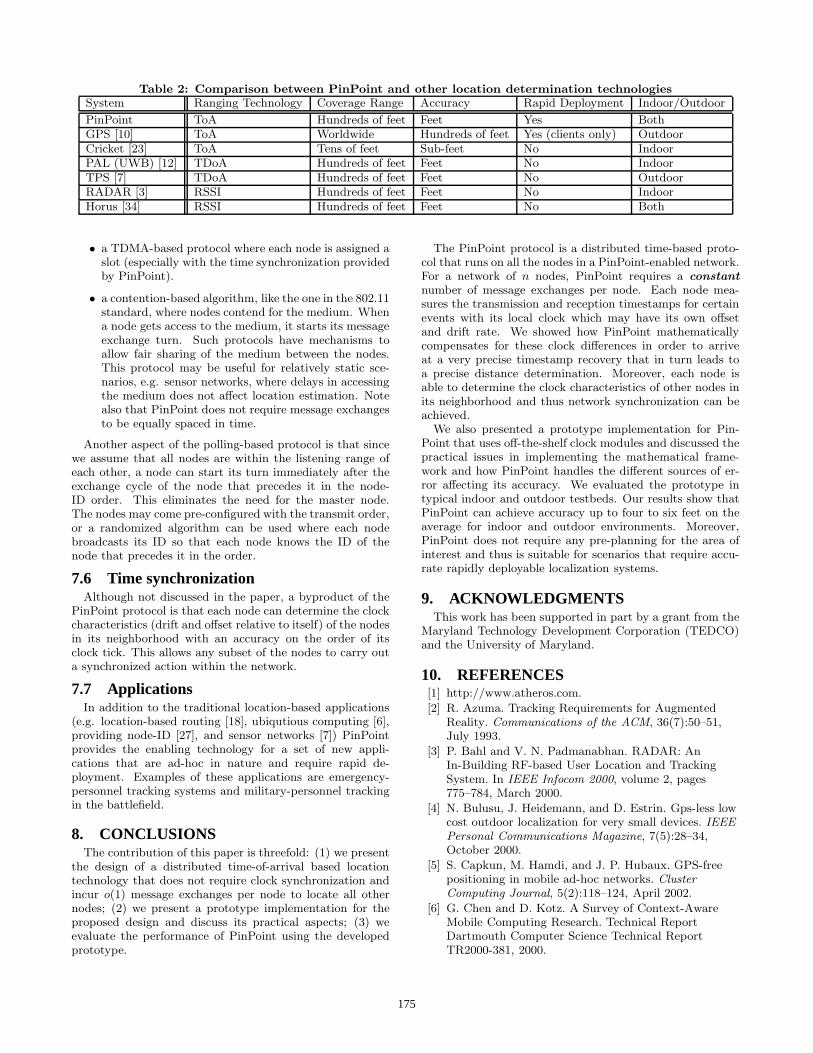
Table 2: Comparison between PinPoint and other location determination technologiesSystem Ranging Technology Coverage Range Accuracy Rapid Deployment Indoor/Outdoor
PinPoint ToA Hundreds of feet Feet Yes BothGPS [10] ToA Worldwide Hundreds of feet Yes (clients only) OutdoorCricket [23] ToA Tens of feet Sub-feet No IndoorPAL (UWB) [12] TDoA Hundreds of feet Feet No IndoorTPS [7] TDoA Hundreds of feet Feet No OutdoorRADAR [3] RSSI Hundreds of feet Feet No IndoorHorus [34] RSSI Hundreds of feet Feet No Both
• a TDMA-based protocol where each node is assigned aslot (especially with the time synchronization providedby PinPoint).
• a contention-based algorithm, like the one in the 802.11standard, where nodes contend for the medium. Whena node gets access to the medium, it starts its messageexchange turn. Such protocols have mechanisms toallow fair sharing of the medium between the nodes.This protocol may be useful for relatively static sce-narios, e.g. sensor networks, where delays in accessingthe medium does not affect location estimation. Notealso that PinPoint does not require message exchangesto be equally spaced in time.
Another aspect of the polling-based protocol is that sincewe assume that all nodes are within the listening range ofeach other, a node can start its turn immediately after theexchange cycle of the node that precedes it in the node-ID order. This eliminates the need for the master node.The nodes may come pre-configured with the transmit order,or a randomized algorithm can be used where each nodebroadcasts its ID so that each node knows the ID of thenode that precedes it in the order.
7.6 Time synchronizationAlthough not discussed in the paper, a byproduct of the
PinPoint protocol is that each node can determine the clockcharacteristics (drift and offset relative to itself) of the nodesin its neighborhood with an accuracy on the order of itsclock tick. This allows any subset of the nodes to carry outa synchronized action within the network.
7.7 ApplicationsIn addition to the traditional location-based applications
(e.g. location-based routing [18], ubiqutious computing [6],providing node-ID [27], and sensor networks [7]) PinPointprovides the enabling technology for a set of new appli-cations that are ad-hoc in nature and require rapid de-ployment. Examples of these applications are emergency-personnel tracking systems and military-personnel trackingin the battlefield.
8. CONCLUSIONSThe contribution of this paper is threefold: (1) we present
the design of a distributed time-of-arrival based locationtechnology that does not require clock synchronization andincur o(1) message exchanges per node to locate all othernodes; (2) we present a prototype implementation for theproposed design and discuss its practical aspects; (3) weevaluate the performance of PinPoint using the developedprototype.
The PinPoint protocol is a distributed time-based proto-col that runs on all the nodes in a PinPoint-enabled network.For a network of n nodes, PinPoint requires a constantnumber of message exchanges per node. Each node mea-sures the transmission and reception timestamps for certainevents with its local clock which may have its own offsetand drift rate. We showed how PinPoint mathematicallycompensates for these clock differences in order to arriveat a very precise timestamp recovery that in turn leads toa precise distance determination. Moreover, each node isable to determine the clock characteristics of other nodes inits neighborhood and thus network synchronization can beachieved.
We also presented a prototype implementation for Pin-Point that uses off-the-shelf clock modules and discussed thepractical issues in implementing the mathematical frame-work and how PinPoint handles the different sources of er-ror affecting its accuracy. We evaluated the prototype intypical indoor and outdoor testbeds. Our results show thatPinPoint can achieve accuracy up to four to six feet on theaverage for indoor and outdoor environments. Moreover,PinPoint does not require any pre-planning for the area ofinterest and thus is suitable for scenarios that require accu-rate rapidly deployable localization systems.
9. ACKNOWLEDGMENTSThis work has been supported in part by a grant from the
Maryland Technology Development Corporation (TEDCO)and the University of Maryland.
10. REFERENCES[1] http://www.atheros.com.
[2] R. Azuma. Tracking Requirements for AugmentedReality. Communications of the ACM, 36(7):50–51,July 1993.
[3] P. Bahl and V. N. Padmanabhan. RADAR: AnIn-Building RF-based User Location and TrackingSystem. In IEEE Infocom 2000, volume 2, pages775–784, March 2000.
[4] N. Bulusu, J. Heidemann, and D. Estrin. Gps-less lowcost outdoor localization for very small devices. IEEEPersonal Communications Magazine, 7(5):28–34,October 2000.
[5] S. Capkun, M. Hamdi, and J. P. Hubaux. GPS-freepositioning in mobile ad-hoc networks. ClusterComputing Journal, 5(2):118–124, April 2002.
[6] G. Chen and D. Kotz. A Survey of Context-AwareMobile Computing Research. Technical ReportDartmouth Computer Science Technical ReportTR2000-381, 2000.
175
[7] X. Cheng, A. Thaeler, G. Xue, and D. Chen. TPS: ATime-Based Positioning Scheme For Outdoor SensorNetworks. In Proceedings of IEEE Infocom, volume 4,pages 2685–2696, 2004.
[8] L. Doherty, K. Pister, and L. E. Ghaoui. ConvexPosition Estimation in Wireless Sensor Networks. InProceedings of IEEE Infocom, volume 3, pages1655–1663, 2001.
[9] G. Durisi and G. Romano. Simulation analysis andperformance evaluation of an UWB system in indoormultipath channel. In IEEE Conference on UltraWideband Systems and Technologies, pages 255–258,2002.
[10] P. Enge and P. Misra. Special issue on GPS: TheGlobal Positioning System. Proceedings of the IEEE,87(1):3–172, January 1999.
[11] R. J. Fontana and S. J. Gunderson. Ultra-widebandprecision asset location system. In IEEE Conferenceon Ultra Wideband Systems and Technologies, pages147–150, May 2002.
[12] R. J. Fontana, E. Richley, and J. Barney.Commercialization of an ultra wideband precisionasset location system. In IEEE Conference on UltraWideband Systems and Technologies, pages 369– 373,November 2003.
[13] T. He, C. Huang, B. M. Blum, J. A. Stankovic, andT. Abdelzaher. Range-Free Localization Schemes forLarge Scale Sensor Networks. In 9th ACMMOBICOM, pages 81–95, 2003.
[14] X. Ji. Sensor Positioning in Wireless Ad-hoc SensorNetworks with Multidimensional Scaling. InProceedings of IEEE InfoCom, volume 4, pages2652–2661, 2004.
[15] P. Krishnan, A. Krishnakumar, W. H. Ju, C. Mallows,and S. Ganu. A System for LEASE: LocationEstimation Assisted by Stationary Emitters for IndoorRF Wireless Networks. In IEEE Infocom, volume 2,pages 1001–1011, March 2004.
[16] J. Krumm et al. Multi-camera multi-person trackingfor Easy Living. In 3rd IEEE Int’l Workshop onVisual Surveillance, pages 3–10, Piscataway, NJ, 2000.
[17] A. M. Ladd, K. Bekris, A. Rudys, G. Marceau, L. E.Kavraki, and D. S. Wallach. Robotics-Based LocationSensing using Wireless Ethernet. In 8th ACMMobiCom, pages 23–28, Atlanta, GA, September 2002.
[18] J. C. Navas and T. Imielinski. Geocast- GeographicAddressing and Routing. In 3rd ACM MOBICOM,volume 3, pages 66–76, 1997.
[19] D. Niculescu and B. Nath. Ad-hoc Positioning System(APS). In IEEE GlobeCom, volume 5, pages2926–2931, 2001.
[20] D. Niculescu and B. Nath. Ad Hoc Positioning System(APS) Using AoA. In Proceedings of IEEE Infocom,volume 3, pages 1734– 1743, 2003.
[21] R. J. Orr and G. D. Abowd. The Smart Floor: AMechanism for Natural User Identification andTracking. In Conference on Human Factors inComputing Systems (CHI 2000), pages 1–6, TheHague, Netherlands, April 2000.
[22] V. N. Padmanabhan and L. Subramanian.Determining the Geographic Location of InternetHosts. In Proceedings of ACM SIGMETRICS, pages324–325, 2001.
[23] N. B. Priyantha, A. Chakraborty, andH. Balakrishnan. The Cricket Location-SupportSystem. In 6th ACM MOBICOM, pages 32–43,Boston, MA, August 2000.
[24] T. S. Rappaport. Wireless Communications Principlesand Practice. Pearson Education, second edition, 2002.
[25] A. Savvides, C. C. Han, and M. Srivastava. DynamicFine-Grained Localization in Ad-hoc Networks ofSensors. In 7th ACM MOBICOM, pages 166–179,2001.
[26] A. Savvides, H. Park, and M. B. Srivastava. The Bitsand Flops of The n-hop Multilateration Primitive forNode Localization Problems. In the first ACMinternational workshop on Wireless Sensor Networksand Applications, pages 112–121, 2002.
[27] C. Schurgers, G. Kulkarni, and M. Srivastava.Distributed On-Demand Address Assignment inWireless Sensor Networks. IEEE Transactions onParallel and Distributed Systems, 13(10):1056–1065,January-March 2002.
[28] S. Tekinay. Special issue on Wireless GeolocationSystems and Services. IEEE CommunicationsMagazine, April 1998.
[29] The Institute of Electrical and Electronics Engineers,Inc. IEEE Standard 802.11 - Wireless LAN MediumAccess Control (MAC) and Physical Layer (PHY)specifications. 1999.
[30] R. Want, A. Hopper, V. Falco, and J. Gibbons. TheActive Badge Location System. ACM Transactions onInformation Systems, 10(1):91–102, January 1992.
[31] M. Welborn. System considerations for ultra-widebandwireless networks. In Proceedings of IEEE Radio andWireless Conference (RAWCON), pages 5–8, 2001.
[32] J. Werb and C. Lanzl. Designing a Positioning Systemfor Finding Things and People Indoors. IEEESpectrum, 35(9):71–78, September 1998.
[33] A. Youssef, M. Youssef, M. Younis, and A. Agrawala.The Overlapped K-hop (OK) Clustering Algorithm.Technical Report CS-TR-4735, Department ofComputer Science, University of Maryland CollegePark, July 2005.
[34] M. Youssef and A. Agrawala. The Horus WLANLocation Determination System. In ThirdInternational Conference on Mobile Systems,Applications, and Services (MobiSys 2005), pages205–218, June 2005.
176