plan of development - basin & range watchbasinandrangewatch.org/first solar stateline_ca...
TRANSCRIPT

Stateline Solar Farm Page iSeptember 3, 2010
Plan of Development
Copyright © 2009 - 2010 First Solar Inc. All Rights Reserved
Table of Contents Volume I
1.0 Introduction ..................................................................................................................................................1 1.1 Proponent Introduction: First Solar ....................................................................................................2 1.2 Project Background.............................................................................................................................2 1.3 Type of Facility, Planned Uses, and Generation Output....................................................................3 1.4 Project Permitting and Construction Schedule...................................................................................3 1.5 Proponent’s Purpose and Need for the Project..................................................................................4
2.0 Project Description ......................................................................................................................................7 2.1 Project Study Area ..............................................................................................................................7
2.1.1 Solar Farm Site and Access Corridor ...................................................................................7 2.1.2 Transmission Corridor and Substation Interconnection Location........................................7
2.2 General Facility Description, Design, and Operations .......................................................................7 2.2.1 Existing Site Conditions.........................................................................................................7 2.2.2 Land Use Planning and Zoning ............................................................................................8 2.2.3 Geological Conditions ...........................................................................................................9 2.2.4 Hydrological Conditions ......................................................................................................10 2.2.5 Biological Resources...........................................................................................................13 2.2.6 Cultural and Paleontologic Resources ...............................................................................17 2.2.7 Project Location, Land Ownership, and Jurisdiction ..........................................................21 2.2.8 Legal Description.................................................................................................................21 2.2.9 Power Plant Facilities ..........................................................................................................22 2.2.10 First Solar Cadmium Telluride (CdTe) PV Technology......................................................22 2.2.11 PV Arrays and Combining Switchgear ...............................................................................24 2.2.12 Monitoring and Maintenance Facility ..................................................................................26 2.2.13 Meteorological Station.........................................................................................................26 2.2.14 Other Ancillary Facilities......................................................................................................27 2.2.15 Site Security and Fencing ...................................................................................................27 2.2.16 Temporary Construction Facilities ......................................................................................28 2.2.17 Acreage and Dimensions of Project Facilities and Components.......................................28 2.2.18 Geotechnical Studies ..........................................................................................................28 2.2.19 Water Uses and Sources ....................................................................................................29 2.2.20 Erosion Control and Storm Water Drainage.......................................................................30 2.2.21 Vegetation Treatment and Weed Management .................................................................30 2.2.22 Waste and Hazardous Materials Management..................................................................31 2.2.23 Reusable and Recyclable Materials/PV Module Recycling ...............................................32 2.2.24 Fire Protection .....................................................................................................................32 2.2.25 Electrical Components, New Equipment, and Existing System Upgrades .......................33
Stateline Solar Farm Page iiSeptember 3, 2010
Plan of Development
Copyright © 2009 - 2010 First Solar Inc. All Rights Reserved
2.2.26 Interconnection to Electrical Grid ........................................................................................33 2.2.27 Spill Prevention and Containment ......................................................................................33 2.2.28 Health and Safety Program.................................................................................................35
2.3 Other Federal, State, and Local Agency Permit Requirements ......................................................35 2.3.1 Federal Permits and Status.................................................................................................35 2.3.2 State Permits and Status ....................................................................................................37 2.3.3 Local Permits and Status ....................................................................................................38
2.4 Financial and Technical Capability ...................................................................................................38
3.0 Construction of Facilities..........................................................................................................................39 3.1 Design, Layout, Installation, and Construction Processes ..............................................................39 3.2 Construction and Operations Approach – Phased Project ..............................................................39 3.3 Access and Transportation System, Component Delivery, Worker Access ...................................39 3.4 Construction Workforce Numbers, Vehicles, Equipment, Timeframes ...........................................39 3.5 Surveying and Staking ......................................................................................................................40 3.6 Site Preparation, Clearing, Grading, and Compaction.....................................................................41
3.6.1 Preconstruction Activities ......................................................................................................41 3.6.2 Site Preparation .....................................................................................................................41 3.6.3 Construction and Installation ..................................................................................................43
3.7 Solar Array Assembly and Construction...........................................................................................44 3.8 Gravel, Aggregate, and Concrete Needs and Sources ...................................................................44 3.9 Solar Module and Electrical Construction Activities.........................................................................44 3.10 Aviation Lighting (Power Towers, Transmission).............................................................................45 3.11 Site Stabilization, Protection, and Reclamation Practices ...............................................................45
4.0 Related Facilities and Systems................................................................................................................47 4.1 Transmission System Interconnect ..................................................................................................47
4.1.1 Existing Transmission System............................................................................................47 4.1.2 Proposed Transmission System.........................................................................................47 4.1.3 Ancillary Facilities and Substations ....................................................................................48 4.1.4 Status of Power Purchase Agreements (PPAs).................................................................48 4.1.5 General Design and Construction Standards.....................................................................48
4.2 Gas Supply Systems.........................................................................................................................48 4.3 Other Related Systems.....................................................................................................................48
4.3.1 Communications System Requirements ............................................................................48

Stateline Solar Farm Page iiiSeptember 3, 2010
Plan of Development
Copyright © 2009 - 2010 First Solar Inc. All Rights Reserved
5.0 Operations and Maintenance ...................................................................................................................49 5.1 Operation and Facility Maintenance Needs .....................................................................................49 5.2 Maintenance Activities ......................................................................................................................49 5.3 Operations Workforce and Equipment .............................................................................................49
6.0 Environmental Considerations ................................................................................................................51
7.0 Supplemental Information ........................................................................................................................53 7.1 Engineering and Civil Design............................................................................................................53
7.1.1 Facility Survey and Design Drawing Standards .................................................................53 7.1.2 Final Engineering and Civil Design Packages ...................................................................53 7.1.3 Watershed and Drainage Analysis and Calculations.........................................................53 7.1.4 Watershed Protection and Erosion Control Drawings .......................................................53 7.1.5 Final Site Grading Plans .....................................................................................................53
7.2 Alternatives Considered by the Applicant.........................................................................................53 7.2.1 Alternative Site Evaluation Criteria .....................................................................................53 7.2.2 Alternatives Considered but not Carried Forward by Proponent.......................................54 7.2.3 Alternative Site Configurations to be Analyzed During NEPA...........................................55 7.2.4 Comparison of Alternative Site Configurations...................................................................56
7.3 Facility Management Plans...............................................................................................................56 7.3.1 Storm Water Pollution Prevention and Protection Plan .....................................................56 7.3.2 Hazardous Materials Management Plan ............................................................................58 7.3.3 Spill Prevention Control and Countermeasure Plan ..........................................................58 7.3.4 Waste Management Plan....................................................................................................58 7.3.5 Integrated Weed Management Plan...................................................................................58 7.3.6 Health and Safety Plan........................................................................................................59 7.3.7 Environmental Inspection and Compliance Monitoring Plan .............................................59 7.3.8 Facility Decommissioning....................................................................................................59
List of Figures
Figure 2-1 Representative PV Array Photograph .......................................................................................25 Figure 2-2 Representative Power Conversion Station Photograph ...........................................................25 Figure 2-3 Representative PV Combining Switchgear Photograph...........................................................26 Figure 2-4 Representative Meteorological Station Photograph .................................................................27
Stateline Solar Farm Page ivSeptember 3, 2010
Plan of Development
Copyright © 2009 - 2010 First Solar Inc. All Rights Reserved
List of Tables Table 1-1 Preliminary Stateline Solar Farm Project Schedule ..........................................................................4
Table 2-1 Existing Peak Flow Rates ..........................................................................................................11
Table 2-2 Developed Condition Peak Flow Rates.....................................................................................11
Table 2-3 Flow Rate Comparison ..............................................................................................................12
Table 2-3 Legal Description of the Solar Farm Site and Access Corridor Project Study Area ................21
Table 2-4 Legal Description of the Proposed Transmission Corridor Study Area....................................22 Table 2-5 Approximate Size of Project Facilities and Components..........................................................29 Table 2-6 Chemicals at Project Site during Construction..........................................................................31 Table 2-7 Chemicals at Project Site during Operation ..............................................................................31 Table 2-8 Status of Project Federal Permits and Authorizations ..............................................................36 Table 2-9 Status of Project State Permits and Authorizations ..................................................................37 Table 2-10 Status of Project Local Permits and Authorizations..................................................................38 Table 3-1 Maximum Construction Equipment /Vehicles On Site by Phase..............................................40 Table 3-2 Proposed Ground Disturbance-Solar Farm Site .......................................................................43 Table 5-1 Daily Vehicle Trips During Project Operation............................................................................49 Table 7-1 Comparison of Alternative Site Configurations .........................................................................57
List of Appendices (Volume I) Appendix A Site Plan Package – Alternative A
Appendix B Site Plan Package – Alternative B (Preferred Alternative)
Appendix C Site Plan Package – Alternative C Appendix D Existing Easements Information Appendix E Environmental Considerations Table Appendix F Phase I Geotechnical Report Appendix G Biological Resources Technical Report

Stateline Solar Farm Page vSeptember 3, 2010
Plan of Development
Copyright © 2009 - 2010 First Solar Inc. All Rights Reserved
List of Appendices (Volume II) Appendix H Hydrology and Hydraulics Reports H-1 Hydrology and Hydraulics Report – Alternative A H-2 Hydrology and Hydraulics Report – Alternative B Appendix I Cultural Resources Reports I-1 Class I Cultural Resources Survey Report (under separate cover) I-2 Class III Cultural Resources Survey Report (under separate cover) (to be supplied) Appendix J Paleontology Literature/Records Review Appendix K Legal Description

Stateline Solar Farm September 3, 2010
Page vi
Plan of Development
Copyright © 2009 - 2010 First Solar Inc. All Rights Reserved
THIS PAGE INTENTIONALLY LEFT BLANK

Stateline Solar Farm Page 1September 3, 2010
Plan of Development
Copyright © 2009 - 2010 First Solar Inc. All Rights Reserved
1.0 Introduction
First Solar Development, Inc. (First Solar or Applicant) proposes to develop and construct a 300-megawatt (MW) alternating current (AC) solar photovoltaic (PV) energy generating project known as the Stateline Solar Farm (Project). The PV generating facility (Solar Farm), the corridor for the Project’s 220-kilovolt (kV) generation interconnection (gen-tie) transmission line, and the access road would be located on Federal lands managed by the U.S. Department of Interior, Bureau of Land Management (BLM), Needles Field Office. The Solar Farm site is approximately 2 miles south of the California-Nevada border and 0.5 mile west of Interstate 15 (I-15) in eastern San Bernardino County. Sheet 2 of the Site Plan Package (SPP) provided in Appendix B is a vicinity map of the Project site and surroundings. The proposed Project would include the Solar Farm, an on-site substation (Project Substation), the 220 kV gen-tie line within the Transmission Corridor, and an access road within an Access Corridor. The Project would connect to the Southern California Edison (SCE) regional transmission grid via SCE’s Ivanpah Substation, which is not a part of the Project. This Plan of Development (POD) is part of the BLM Right of Way (ROW) grant application process and has been prepared according to the latest BLM POD Guidelines published on July 3, 2008.
To provide a sufficiently large area to evaluate a reasonable range of alternatives for the Project’s Solar Farm, First Solar established a Project Study Area approximately 5,454 acres in size (see Sheet 3 of Appendix B). The Preferred Project would require approximately 2,153 acres. This includes Preferred Solar Farm Site and Access Corridor (2,114 acres) and the Transmission Corridor (38 acres). Approximately 1,841 acres would be fenced with the Preferred Alternative. The Solar Farm, Transmission Corridor, and Access Corridor would be located entirely on Federal land. The Project Study Area and the Preferred Project Site are depicted in Sheet 3 of Appendix B.
The proposed Project will help California meet its Renewable Portfolio Standard (RPS) goal, which is currently 20 percent of retail electric power sales from renewable sources by 2010 under existing law (Senate Bill 1078), and 33 percent of electrical power retail sales by 2020 under Executive Orders S-14-08 and S-21-09 issued by Governor Schwarzenegger. The Project supports Secretary of the Interior Salazar’s Orders 3283 and 3285, which make developing renewable energy a top national priority. The Project will also help the State achieve the 2006 Global Warming Solutions Act (Assembly Bill [AB] 32) greenhouse gas (GHG) reduction targets, which require California’s GHG emissions to be reduced to 1990 levels by 2020.
When fully operational, the 300-MW Stateline Solar Farm facility would have the capacity to directly convert solar energy to 300 MW of emission-free power using minimal water and producing no waste. This is equivalent to the amount of energy needed to serve nearly 90,000 local California homes each year, and, compared to the CO2 emissions that would be emitted if the same amount of electricity was generated from fossil fuels, implementing the Project would avoid emissions of over 165,000 metric tons of carbon dioxide annually – the equivalent of taking almost 32,000 automobiles off the road. The electricity generated by the Project would be sold to SCE to help meet their RPS requirements.
The Project would employ best practices throughout all aspects of development. First Solar’s advanced PV technology and an efficient, environmentally-sensitive site layout would maximize renewable energy generation potential while minimizing disruption to the Project site and surrounding environment.

Stateline Solar Farm Page 2September 3, 2010
Plan of Development
Copyright © 2009 - 2010 First Solar Inc. All Rights Reserved
Key attributes of the Stateline Solar Farm include:
Direct conversion of sunlight to electricity without the use of water in the power generation process (i.e., no need for cooling water or water to generate steam) and without the generation of wastes;
300 MW of electrical power, a typical capacity for a modern natural gas-fired combined-cycle power plant in California, generated from a renewable source and producing no carbon (or any other air pollutant) emissions and lower noise levels during power generation;
Low-profile, uniform PV arrays approximately five feet in height. No on-site structures, with the exception of utility poles, would be taller than a maintenance building or electrical switchyard;
Minimal water use during Project operation;
Desert tortoise fencing along the site perimeter; and
A pre-funded PV Module Collection and Recycling Program that allows all modules to be collected and recycled at the end of their useful life into new modules or other products.
1.1 Proponent Introduction: First Solar First Solar is a recognized worldwide leader in solar PV manufacturing and development with a considerable project backlog and stellar environmental health and safety track record. First Solar is a U.S.-based corporation with offices in Tempe, Arizona; Perrysburg, Ohio; Oakland, California; Irvine, California; and Bridgewater, New Jersey. First Solar also has multiple PV module manufacturing facilities, located in Perrysburg, Ohio; Germany; and Malaysia, with a total manufacturing capacity to exceed 1,300 MW annually by the end of 2010. First Solar’s current market capitalization is approximately $10.8 billion (as of August 26, 2010), the largest in the solar power industry.
The Project would utilize First Solar’s proven thin film cadmium telluride (CdTe) PV technology, which is readily scalable to the Project’s size. First Solar has developed and is continually refining manufacturing technologies that drive down the cost of its modules in order to offer reliable solar power at a price that is cost-competitive with other forms of non-renewable power generation. At the same time, the firm has continued to emphasize methods and programs for manufacturing and construction that are environmentally sustainable, such as its pre-funded module collection and recycling program.
First Solar has manufactured over 2,000 MW of solar PV modules and has the manufacturing capacity to supply the requirements of the Stateline Solar Farm. The majority of First Solar’s modules have been placed in service in European Union (EU) countries such as Germany where they have met very stringent EU environmental regulations.
First Solar recently completed the 10 MW El Dorado project in Nevada; a 20 MW project in Sarnia, Ontario, Canada; the 30 MW Cimarron project in New Mexico; and the 21 MW Blythe Solar 1 project in Riverside County, California. The 48 MW Copper Mountain project is currently under construction in Nevada. There also are other First Solar PV projects currently in the permitting process in California, such as the 550-MW Desert Sunlight project in Riverside County and the 550-MW Topaz project in San Luis Obispo County.
1.2 Project Background Between December 2006 and December 2008 applications were filed for use of a total of 6,400 acres of Federal land for the Stateline Solar Farm. The Project was originally planned to be a 300 MW project using

Stateline Solar Farm Page 3September 3, 2010
Plan of Development
Copyright © 2009 - 2010 First Solar Inc. All Rights Reserved
OptiSolar PV technology. On April 3, 2009, the Applicant for the Project, previously named OptiSolar, underwent a name change as a result of the merger between OptiSolar and First Solar, which resulted in OptiSolar becoming a wholly-owned subsidiary of First Solar. A letter indicating this change was sent to the BLM Needles Field Office on May 4, 2009. On August 5, 2009, First Solar submitted an updated SF 299 application indicating the change of name from OptiSolar, Inc. to First Solar Development, Inc. and to include the lands being considered for the Transmission Corridor. On April 23, 2010, a Draft POD was submitted, which included a redesigned project using First Solar PV modules with Preferred Alternative on 3,011 acres. This alternative is included in this POD submittal as Alternative C (Appendix C). A much larger Project Study Area than what is required for the Solar Farm has been examined (5,518 acres), allowing First Solar to site the Project within the overall Project Study Area in a manner that is both technically sound and efficient and that also avoids sensitive environmental and other resources.
1.3 Type of Facility, Planned Uses, and Generation Output The Stateline Solar Farm is a 300-MW solar PV energy generating facility. The facility would use First Solar’s thin film CdTe PV modules to produce clean, renewable energy for California customers. The project’s entire energy output would be purchased by SCE (see Section 4.1.4). The Project includes an approximately 2.3-mile 220-kV gen-tie line to interconnect with the SCE regional transmission system at SCE’s planned Ivanpah Substation. First Solar submitted an interconnection request for the project with the California Independent System Operator (CAISO) on January 9, 2007. CAISO’s Transition Cluster Phase 2 Study for projects in this area (including the Stateline Solar Farm) was released on August 13, 2010.
1.4 Project Permitting and Construction Schedule The BLM will be the lead Federal agency for approving the Project and would issue a ROW grant authorizing the Project’s construction, operation, and use of Federal lands. The decision regarding the issuance of the ROW grant will be based in part on an evaluation of the Project’s potential environmental effects through the National Environmental Policy Act (NEPA) review process and the requirements of the Federal Land Policy and Management Act (FLPMA). As noted above, the NEPA process will involve the preparation of an Environmental Impact Statement (EIS) that will detail the Project’s expected environmental impacts and mitigation measures to avoid or minimize identified impacts. The NEPA review process commences once the BLM has deemed the POD complete, issued a Notice of Intent (NOI) and selected a consultant to prepare the EIS.
First Solar recognizes the importance of timely and clear communication with involved public agencies and community stakeholders. Early in the Project development process, First Solar met with public agencies, including the BLM, San Bernardino County Planning Department, as well as with community stakeholders and neighboring landowners. These meetings were held to familiarize these groups with the Stateline Solar Farm and to begin addressing their unique needs, concerns, and questions about the Project. First Solar is currently in the process of initiating discussions and consultation processes with other involved Federal, State, and local permitting agencies. These include the U.S. Fish and Wildlife Service (USFWS), the U.S. Army Corps of Engineers (USACE) and the California Department of Fish and Game (CDFG), and other agencies with jurisdiction over the Project in conjunction with the BLM’s ROW grant approval process. Section 2.3 of the POD provides detail relating to the Federal, State and local permits required for the Project.
The construction of the Project would not begin until after all applicable approvals and permits have been obtained. First Solar estimates that it would take approximately 15 months from initial construction mobilization to completion of construction. Table 1-1 shows key milestone dates associated with Project permitting and approvals, as well as Project construction. Once construction is completed, the Project would be in operation for 30 years. Note that the project timing takes into consideration SCE’s El Dorado to

Stateline Solar Farm Page 4September 3, 2010
Plan of Development
Copyright © 2009 - 2010 First Solar Inc. All Rights Reserved
Ivanpah transmission project, including the Ivanpah substation, which is anticipated to be completed in July 2013.
Table 1-1 Preliminary Stateline Solar Farm Project Schedule
Project Milestone Start Date Date Complete Draft POD Submittal April 23, 2010 April 23,2010 Final POD Submittal September 3, 2010 September 3, 2010 POD and ROW application reviewed and determined complete October 1, 2010 October 1, 2010 BLM issues NOI for EIS October 16, 2010 October 16, 2010
Project scoping and scoping meetings conducted October 16, 2010 November 16, 2010
BLM issues Notice of Availability (NOA) of Draft EIS May 2011 May 2011 90-Day DEIS/ Land Use Plan Amendment public review period and meetings May 2011 August 2011
BLM submits Biological Assessment (BA) to USFWS (starts 135-day consultation) November, 2010 May 2011
USFWS issues Biological Opinion (BO) May 2011 May 2011 BLM issues NOA of Final EIS/Proposed Land Use Plan Amendment October 2011 December 2011
Protest Period for Proposed Land Use Plan Amendment December 2011 January 2012 BLM issues Record of Decision (ROD) / ROW Grant and CPUC issues PTC January 2012 January 2012
Appeal Period January 2012 June 2012 Construction Permits (e.g., local building permit and encroachment permits and final pre-construction planning May 2012 June 2013
Project Construction March 2013 July 2014 Note: SCE estimates that the El Dorado to Ivanpah transmission project, including the Ivanpah Substation, will be completed
in July 2013.
1.5 Proponent’s Purpose and Need for the Project The purpose of this Project is to create a clean, renewable source of electricity that helps meet California’s growing demand for power and helps fulfill national and State renewable energy and GHG goals. Solar energy provides a sustainable, renewable source of power that helps reduce fossil fuel dependence and GHG emissions.
The California Energy Commission forecasts that electricity consumption in California will increase by 0.8 percent per year from 2010 to 20181. Peak demand is expected to increase by 1.1 percent annually over
1 California Energy Commission. June 2009. California Energy Demand 2010-2020. Staff Draft Forecast. Staff Draft Report. CEC-200-2009-012-SD.

Stateline Solar Farm Page 5September 3, 2010
Plan of Development
Copyright © 2009 - 2010 First Solar Inc. All Rights Reserved
the same period. The Project would add 300 MW of renewable generating capacity to California’s energy system; in addition, this solar energy would be generated during peak hours of consumption and would help local utilities in meeting increases in peak demand.
This Project will support California in meeting the RPS mandate, which requires California’s investor-owned utilities to supply 20 percent of its total electricity through renewable energy generation by the 2010 and 33 percent of its electricity supply from renewable energy by 2020.
In addition, the Project will help meet the goals set forth in AB 32, which requires that the State's GHG emissions be reduced to 1990 levels by 2020, a roughly 25 percent reduction compared to business-as-usual estimates. Considering the entire process, from raw material sourcing through end-of-life-cycle collection and recycling, the Project’s 300 MW of additional generating capacity would produce a tiny fraction of the GHG emissions of a similar-capacity fossil fuel plant.
Federal policy requires government agencies to facilitate the development of renewable energy sources. Executive Order 13212, issued in May 2001, mandates that Federal agencies act expediently and in a manner consistent with applicable laws to increase the “production and transmission of energy in a safe and environmentally sound manner.” The Energy Policy Act of 2005 requires the Department of the Interior (of which BLM is a part), to approve at least 10,000 MW of renewable energy generation on public lands by 2015. In early 2009, Secretary of Interior Salazar issued Orders 3283 and 3285, making the production, development, and delivery of renewable energy top priorities for the Department of Interior.
Solar electricity generation is an important component of each of the Federal and State policy goals described above. Among other desirable attributes, the Stateline Solar Farm site provides excellent solar resource availability and contains lands that are open, generally flat and uniquely situated near existing transmission lines and roadways. Due to its priority interconnection position with the CAISO, the Project will interconnect to a newly-upgraded 220 kV transmission line, the El Dorado-Ivanpah line.
Part of the government’s efforts to promote renewable energy depend on the ultimate development of increasingly economical facilities that drive down the price of renewable energy, and ultimately enable it to compete in the market place with fossil fuel facilities. The development of large, utility-scale projects enables solar panel manufacturers such as First Solar to achieve significant economies of scale in the manufacturing process. This is evidenced by the company’s success in driving down the cost of solar modules from $3 per watt five years ago when the company’s annual output was 25 MW, compared to today when the cost has been driven to 76 cents/watt (as of Quarter 2, 2010), with over 1,300 MW of manufacturing capacity.
Additional Project objectives include:
Establish 300 MW of generating capacity for emission-free PV solar electricity in an area of high solar insolation and in proximity to existing transmission infrastructure, while avoiding, minimizing, and mitigating the impacts to environmentally sensitive areas;
Develop a project that is feasible to construct and operate while providing utility customers with a cost-competitive, cleaner alternative to conventionally generated electricity;
Provide community benefits, through new jobs, spending in local businesses and additional sales tax revenues;
Employ an average of approximately 400 on-site workers during the 15-month construction period;

Stateline Solar Farm September 3, 2010
Page 6
Plan of Development
Copyright © 2009 - 2010 First Solar Inc. All Rights Reserved
Interconnect to the newly-upgraded SCE El Dorado-Ivanpah transmission line, which is in a federally designated transmission corridor near the project site; and
Generate electricity in an arid environment with minimal water use.
First Solar has considered alternatives for siting the Solar Farm within the overall Project Study Area. The Solar Farm alternatives considered are addressed in POD Section 7.2, and in Appendices A and C.
First Solar’s selection of the Project Study Area and Preferred Project Site over other alternatives is based on a number of criteria. These siting criteria include; 1) a contiguous site with flat topography that is large enough for a 300 MW facility, 2) avoiding areas that are sensitive, such as designated wilderness, Areas of Critical Environmental Concern (ACECs), washes, etc., 3) avoiding high quality habitat for listed species (e.g., choosing a Project site in Category III [lowest quality] desert tortoise habitat, 4) proximity to 220-kV (or higher) transmission facilities with sufficient capacity for project output and suitable locations for interconnection, and 5) good highway access and (6) available for sale or lease/ROW at a reasonable cost.

Stateline Solar Farm Page 7September 3, 2010
Plan of Development
Copyright © 2009 - 2010 First Solar Inc. All Rights Reserved
2.0 Project Description
2.1 Project Study Area The Project Study Area is a largely vacant, undeveloped, and relatively flat land area located in the Ivanpah Valley of the Mojave Desert in eastern San Bernardino County, along the western flank of Ivanpah Dry Lake. The Project Study Area contains existing transmission lines, telephone lines and pipelines, as well as dirt roads. The Preferred Solar Farm Site is located approximately 2 miles south of the California-Nevada border and 0.5 mile west of U.S. Interstate 15 (I-15) (Sheet 3, Appendix B).
The locations of the Project Study Area and the Preferred Project Site (the Project footprint) are shown on Sheets 3 and 4, Appendix B. The Project Study Area encompasses 5,518 acres. This acreage includes 5,454 acres studied for siting of the Solar Farm Site and 64 acres considered for the Transmission Corridor route between the Solar Farm and the Ivanpah Substation.
The Project Study Area consists of substantially more acreage than will ultimately be needed for the Project, so that the necessary studies (i.e., biological and cultural surveys) of a reasonable range of Solar Farm configurations and Transmission Corridor alternatives can be performed that will allow the Project to achieve its goals regardless of which site configuration ultimately proves most suitable.
2.1.1 Solar Farm Site and Access Corridor As shown on Sheets 3 and 4 of Appendix B, the Preferred Solar Farm Site encompasses approximately 2,114 acres. The site would be accessed via a 25-foot-wide, 1.7-mile-long gravel access road (see Appendix B Sheet 34), which is included in the Preferred Solar Farm Site acreage. The portions of the Project Study Area considered for the Solar Farm Site and Access Corridor are located entirely on BLM-managed public land that is largely undeveloped, but is crossed by several existing unimproved roads and transmission lines and contains previously disturbed lands (see Appendix B Sheets 6 through 9).
2.1.2 Transmission Corridor and Substation Interconnection Location The Project expects to interconnect with the regional transmission system via a 220-kV gen-tie line that will exit the southwestern portion of the Preferred Solar Farm Site and follow a 150-foot-wide transmission ROW (Transmission Corridor) to SCE’s proposed Ivanpah Substation, which would be located approximately 2.3 miles south of the Preferred Solar Farm Site (see Appendix B Sheets 3 and 4).
2.2 General Facility Description, Design, and Operations 2.2.1 Existing Site Conditions The Project Study Area is a vacant, undeveloped, and relatively flat land area located in the Ivanpah Valley along the western flank of Ivanpah Dry Lake in eastern San Bernardino County, approximately 2 miles south of the Nevada-California border and 0.5 mile west of I-15 (Sheet 2, Appendix B). The entire Project Study Area, including the transmission line corridor, is on public land administered by the Bureau of Land Management, Needles Field Office. The Project Study Area is located approximately 2 miles southwest of Primm, Nevada and approximately 7 miles north of Wheaton Springs, California. The Primm Valley Golf Club is located adjacent to the southeast corner of the Project Study Area. The golf club is accessed via the Yates Well Road exit from I-15, which is also the southern access for the Project Study Area. There are no known residences within 0.5 mile of the Project Study Area.

Stateline Solar Farm Page 8September 3, 2010
Plan of Development
Copyright © 2009 - 2010 First Solar Inc. All Rights Reserved
Also located in the vicinity of the Project Study Area is a major natural gas power plant, located about 1.5 miles east of Primm and the Union Pacific Railroad, located about one mile east of the site. The Project Study Area is crossed by two major power transmission corridors, one along the northern border of the Project Study Area, and one running through the southeast corner of the Project Study Area. The Project Study Area is also crossed by a major gas pipeline, which runs parallel and just south of the northern power line corridor (Sheets 5 and 6, Appendix B).
Several existing uses (transmission corridors, dirt roads, wells, locatable mineral sites, etc.) cross or are located within the Project Study Area and/or Preferred Solar Farm Site (Sheet 9, Appendix B). Appendix D provides data on ownership of the known existing easements crossing the Preferred Solar Farm Site and the Preferred Transmission Corridor. The Appendix D also provides the locations of the existing uses and easements and the use and dimensions of the corridors, as available, within the respective areas.
The layout and configuration of facilities that represent the Preferred Solar Farm Site within the Project Study Area accommodate constraints associated with the various easements and facilities to the maximum extent practicable. Appendix B contains ownership map for the Preferred Solar Farm Site and Transmission Corridor (Sheet 9).
2.2.2 Land Use Planning and Zoning The entire Project Study Area, including the Preferred Solar Farm Site, Preferred Transmission Corridor, and Preferred Access Corridor is on Federal land managed by the BLM, Needles Field Office. This land is managed by the BLM pursuant to the California Desert Conservation Area Plan of 1980 as amended (CDCA Plan). The Project Study Area lies within the planning area designated under a 2002 amendment to the CDCA Plan, known as the Northern and Eastern Mojave Coordinated Management Plan (NEMO Plan). According to the NEMO Plan, the entire Project Study Area is located on land classified as Multiple Use Class L (Limited Use). According to the Multiple Use Class definitions provided in the CDCA Plan, solar energy facilities are allowed within Class L areas, as long as NEPA requirements are met. New transmission facilities are allowed in Class L if they are located within designated corridors. The proposed transmission line to SCE’s future Ivanpah Substation is within two, overlapping designated utility corridors, CDCA Utility Corridor BB and West-wide Energy Corridor 225-27. According to guidance provided in the CDCA Plan, power generating facilities that are not specified in the CDCA Plan will be processed by means of a CDCA Plan Amendment. Therefore, a CDCA Plan Amendment will be required as part of BLM’s ROW grant review and approval process for the Stateline Solar Farm.
The Project Study Area is designated as Resource Conservation (RC) in the San Bernardino County General Plan. Electric generation facilities are allowed uses in this land use category; however, because the Project is located completely on Federal land, San Bernardino County will not have discretionary review or permit authority over the Project.
The Project Study Area is not located within the boundaries of any ACEC, Designated Wildlife Management Area (DWMA), Wilderness Area, Wilderness Study Area, or Critical Habitat Unit (CHU) (Sheet 5, Appendix B). The Project Study Area is less than 2 miles west of the Ivanpah Valley DWMA/ACEC and approximately 3.5 miles northwest of the Ivanpah CHU. The Clark Mountain ACEC is located approximately 4 miles to the west. The Stateline Wilderness Area is located less than 1 mile to the northwest and the Mesquite Wilderness Area is located immediately west of the Stateline Wilderness Area. The Mojave Wilderness area is located approximately 6 miles west of the Project Study Area. The closest boundary of the proposed Mojave Trails National Monument is located more than 60 miles southwest of the site.

Stateline Solar Farm Page 9September 3, 2010
Plan of Development
Copyright © 2009 - 2010 First Solar Inc. All Rights Reserved
2.2.3 Geological Conditions The Project is located within the Ivanpah Valley, which is bounded by a series of alluvial fans that slope gently toward Ivanpah Dry Lake. The Project Study Area is generally bounded by the Clark Mountains to the north and west and the Lucy Gray Mountains to the east. While the Project Study Area is located almost entirely within mapped alluvial and lakebed sediments ranging from Pleistocene to Holocene in age, it should be noted that the southwestern portion of the Project Study Area contains an outcropping of Precambrian igneous and metamorphic rock.
Maximum change in ground surface elevation across the site is approximately 130 feet. The upper portions of the alluvial fans slope gently toward Ivanpah Dry Lake with a change in ground elevation on the order of 15 feet of fall per 500 yards of horizontal run (slope of 100:1 horizontal to vertical) or less. The central portion of the site is relatively flat with a change in ground elevation on the order of less than 5 feet of fall per 500 yards of horizontal run (slope of 300:1 horizontal to vertical) or less. The general slope and drainage is toward Ivanpah Dry Lake, except where locally modified by manmade features such as access roads.
A Phase I Geotechnical Reconnaissance Report was prepared for the Project Study Area in July 2008, which determined that the proposed development of the site was considered feasible from a geologic standpoint (Appendix F). A total of thirteen shallow exploratory borings were advanced using a hand auger at various locations across the site to a maximum depth of 9 feet below the existing ground surface. Laboratory samples were tested for density and moisture content, particle size, direct shear, water soluble sulfate (for concrete requirements), corrosion, and thermal conductivity. While the Project Study Area is located almost entirely within mapped alluvial and lakebed sediments from Pleistocene to Holocene in age, the southwestern portion of the Project Study Area contains an outcropping of Precambrian igneous and metamorphic rock.
The Project Study Area is in seismically active southern California, but it does not lie within a designated earthquake fault zone as defined by the Alquist-Priolo Act of 1972 and no faults have been mapped within the Project Study Area. Published geologic maps show three faults near the Project Study Area (see Appendix F, Phase I Geotechnical Report). The Stateline Fault is located roughly parallel and adjacent to the California-Nevada State Boundary, trending from the southeast to the northwest; this fault is shown on maps as completely concealed beneath alluvial deposits and its approximate location is mapped approximately 2 miles from the northern boundary of the Project Study Area. Two smaller faults exist to the northwest of the project site. Both faults trend toward the northwestern portion of the Project Study Area but are concealed by alluvial deposits. No known recent surface rupture has been associated with any of these faults
The closest active faults are the Death Valley Fault, located 51 miles west of the Project Study Area; the Garlock Fault, located 52 miles west of the Project Study Area; and the Black Hills Fault, located 52 miles northeast of the Project Study Area. A search of the earthquake catalogues for California and Southern Nevada identified one earthquake with a magnitude of 5.0 or greater and 10 earthquakes with a magnitude of 4.0 or greater that have occurred within a 100 kilometer radius of the Project Study Area since 1800. Historically, the most severe shaking at the site occurred during a 5.0 magnitude earthquake on May 5, 1939. The published epicenter for this earthquake was located approximately 40.5 miles northeast of the site. Based on the existing geologic information from the site, earthquake-induced ground rupture would not be a significant hazard at the site, but moderate ground shaking should be expected at the site during an earthquake as a result of the proximity of three active faults located approximately 50 miles from the site.
Stateline Solar Farm Page 10September 3, 2010
Plan of Development
Copyright © 2009 - 2010 First Solar Inc. All Rights Reserved
The Project Study Area is considered to have a moderate potential for liquefaction based on the general seismicity of the area, the potential for groundwater beneath the site, and the area’s location within an alluvial valley. Landsliding is not considered a significant concern due to the largely flat topography.
The Phase I Geotechnical Report prepared for the Project indicates that the proposed development of the site is considered feasible from a geologic/geotechnical standpoint. A comprehensive geotechnical investigation report of the Project Study Area, which includes a comprehensive geotechnical survey, subsurface exploration, and evaluation of geotechnical constraints, is expected to be completed in fall 2010. The geotechnical evaluation will include drilling, logging, and sampling of a large number of exploratory borings across the entire site, laboratory testing of encountered soils from various depths, and the preparation of a design-level geotechnical evaluation report.
2.2.4 Hydrological Conditions Regional Hydrology. The Project Study Area is located within the Ivanpah Valley, an 875-square-mile topographically closed basin located in both California and Nevada. Surface water in the watershed drains to and evaporates from either Ivanpah Lake or Roach Lake. The Project Study Area is located in the 340,000 acre Ivanpah South (California) portion of the Ivanpah Valley. Ivanpah South includes the 35-square-mile Ivanpah Lake, several ephemeral waterways, and scattered springs along the mountain front. Overall surface drainage in Ivanpah South is toward Ivanpah Lake (California Department of Water Resources (DWR). 2004. California’s Groundwater-Bulletin 118. Basin Descriptions: Ivanpah Valley Groundwater Basin www.groundwater.water.ca.gov/bulletin118/basin_desc/basins_s.cfm).
The Ivanpah Valley is underlain by a large groundwater basin, the Ivanpah Valley Groundwater Basin. The groundwater basin trends north-south and includes areas in both California and Nevada. The Ivanpah Groundwater Basin is bounded by the bedrock of the Bird Springs Range on the north; the Sheep Mountains, Lucy Grey Range, and New York Mountains on the east; and by the Spring Mountains, Clark Mountains, and Ivanpah Mountains on the west. A low topographic divide separates Ivanpah Valley and Shadow Valley to the south. Groundwater flow in the Ivanpah Groundwater Basin is generally toward the northeast. Within Ivanpah South, groundwater flow is generally toward Ivanpah Lake. Groundwater quality varies throughout the Basin, with high levels of fluoride and sodium seen in some parts of the basin (DWR 2004).
Project Study Area Hydrological Analysis. A Hydrology and Hydraulics Report has been completed for the Preferred Alternative (Alternative B) and Alternative A (see Appendix H). The analysis for the Preferred Alternative is summarized below.
Methodology. Drainage basins were determined from available USGS maps as well as 1-foot topographic contours generated from overflight of the Project Study Area. The hydrology analysis conforms to the San Bernardino County Hydrology Manual, with implementation of the Clark County Regional Flood Control District’s analysis of alluvial fans.
Existing Condition. There are seven existing drainage basins crossing the Project Study Area. Flows are generally from west to east, toward Ivanpah Dry Lake. Two large natural washes cross the Project Study Area (see Appendix B, Sheet 17).Flow rates for the 1.2-year, 10-year, 25-year, and 100-year, 24-hour duration storm events were calculated using the San Bernardino Unit Hydrograph Version 8.1 software. These flow rates are provided in Table 2-1.

Stateline Solar Farm Page 11September 3, 2010
Plan of Development
Copyright © 2009 - 2010 First Solar Inc. All Rights Reserved
Table 2-1 Existing Peak Flow Rates
24-Hour Storm Event (cubic feet per second)
Basin1 Area (acres)
Area (sq. miles)
1.2-Year Event
10-Year Event
25-Year Event
100-Year Event
EX1 3,360 5.25 550 2,648 3,592 5,743 EX2 3,455 5.40 406 2,118 2,897 4,770 EX3 6,657 10.26 556 3,237 4,451 7,473 EX4 2,453 3.83 265 1,560 2,158 3,661
EX5 3,125 4.88 328 1,890 2,606 4,395
EX6 1,526 2.38 270 1,253 1,712 2,731 EX7 3,621 5.66 394 2,188 3,004 5,011
Notes: 1 see Appendix B, Sheet 17 for basin locations
Developed Condition. Project facilities are proposed to be located outside of the 100-year floodplain, except for portions of the perimeter fencing, Transmission Corridor, and Access Corridor, which cross the south wash (Appendix B, Sheet 17). To analyze the developed condition, the curve number (CN) value within the project site boundary was changed from a desert cover type to a graded cover type. Table 2-2 summarizes the developed condition peak flow rate, and Table 2-3 compares the existing condition to the developed condition.
Table 2-2 Developed Condition Peak Flow Rates
24-Hour Storm Event (cubic feet per second)
Basin1 Area (acres)
Area (sq. miles)
1.2-Year Event
10-Year Event
25-Year Event
100-Year Event
DEV1 3,360 5.25 557 2,661 3,605 5,751 DEV2 3,455 5.40 417 2,142 2,923 4,787 DEV3 6,657 10.26 567 3,266 4,483 7,494 DEV4 2,453 3.83 271 1,573 2,172 3,670
DEV5 3,125 4.88 331 1,899 2,616 4,402
DEV6 1,526 2.38 270 1,253 1,712 2,731 DEV7 3,621 5.66 394 2,188 3,004 5,011
Notes: 1 Numbered basin locations are the same for the existing condition and the developed condition, but the notation “DEV” has replaced “EX” to indicate the developed condition or the existing condition, respectively. See Appendix B, Sheet 17 for basin locations.

Stateline Solar Farm Page 12September 3, 2010
Plan of Development
Copyright © 2009 - 2010 First Solar Inc. All Rights Reserved
Table 2-3 Flow Rate Comparison
1.2-Year Event 10-Year Event 25-Year Event 100-Year Event
Basin Change in Flow
(cfs)
Change in Flow
(%)
Change in Flow
(cfs)
Change in Flow
(%)
Change in Flow
(cfs)
Change in Flow
(%)
Change in Flow
(cfs)
Change in Flow
(%) EX1-DEV1 7 1.30 12 0.47 13 0.37 8 0.14 EX2-DEV2 12 2.94 24 1.13 26 0.88 17 0.35 EX3-DEV3 11 1.94 29 0.90 32 0.71 20 0.27 EX4-DEV4 5 2.06 13 0.84 14 0.65 9 0.25
EX5-DEV5 4 1.20 9 0.49 10 0.38 6 0.15
EX6-DEV6 0.3 0.11 0.3 0.02 0.3 0.02 0.1 0.00 EX7-DEV7 0.2 0.06 0.3 0.01 0.3 0.01 0.1 0.00
Total Change (cfs) 40 89 96 61
Average Change (%) 1.37 0.55 0.43 0.17
Note: cfs = cubic feet per second
As indicated in the grading plans (Appendix B, Sheets 19 - 22), to minimize scour, the proposed grading design consists of the cut and fill method in conjunction with the disc, contour grade, and roll method. Approximately 39 percent of the site (719 acres) would be graded with the cut and fill method and approximately 61 percent of the site (1,841 acres) would be developed with the disc, contour grade, and roll method. Native material would be returned to compacted graded areas. The sheet graded areas would eliminate existing low points that convey concentrated runoff. The elimination of these low points would force the runoff to exit the site in a shallow and low-velocity manner. Boundary conditions would also be matched within one foot on all sides. The two natural washes designated as the north wash and south wash (Appendix B, Sheet 17) would remain native.
Debris basins along the upstream side of array areas area also proposed (Appendix B Sheet 23). The debris basin will be constructed along the western boundary of the Proposed Solar Farm Site, excluding the two native drainages, which would not be disturbed. The basins would allow upstream flows to be harnessed prior to entering the site and would collect bed load currently transported down the alluvial fan. The basins would be excavated below natural ground surface to prevent a backwater effect from occurring upstream. Adequately sized rip rap will be provided along the western (upstream) side slope of the basins for erosion control. The captured bed load would be redistributed along the lower (eastern) extent of the array area after storm occurrences. Suspended sediment load would remain in the solution of storm water and would continue over the basins, across the site, and deposit onto Ivanpah Dry Lake similar to current conditions.
Water Quality/Sedimentation. There will be a slight volume increase in flow (between 0.17% and 1.37%) with the Preferred Alternative (Table 2-3), showing nominal change from historic conditions. Sediment basins sized to capture the increase in volume for the 1.2-year storm have been proposed along the downstream boundary of the site (see Sheets 19 and 21 of Appendix B). The flow intercepted by these

Stateline Solar Farm Page 13September 3, 2010
Plan of Development
Copyright © 2009 - 2010 First Solar Inc. All Rights Reserved
basins will stagnate and retain the change in sediment occurring in the 1.2-year storm. By providing these sediment basins, the natural pattern of sediment pattern will not be compromised. The combined effect of debris basins, sheet grading, and sediment basins will be to attenuate the peak flows. Runoff will enter she site as equivalently-distributed sheet flow. Because this flow will be at a shallow depth, velocities will be decreased but the volumes will be maintained. Flow exiting the site will be distributed back into the shallow braided channels to the east. The peak flows and historic storm water outlet locations entering Ivanpah Dry Lake will be maintained.
A Storm Water Pollution Prevention Plan (SWPPP) will also be developed describing construction and post-construction best management practices (BMPs) to manage stormwater and drainage.
Project Study Area Hydraulic Analysis.
Methodology. The HEC-RAS software, developed by the US Army Corps of Engineers, was used to obtain water surface profiles associated with the 100-year storm runoff. To determine the worst-case scenario for evaluating potential scour, two methods have been used. The Zeller-Fullerton equation in conjunction with the Zeller Bend scour equation has been used to anticipate scour depth. The FLO-2D software was also used to analyze sediment transport.
Results. The HEC-RAS software was used to simulate runoff crossing the property at the two well-defined natural wash areas (north wash and south wash, see Sheet 17, Appendix B). The Preferred Alternative would not affect these natural wash areas. With the exception of a portion of the perimeter fencing, Transmission Corridor, and Access Corridor, all permanent facilities would be excluded within 100 feet of the washes, to accommodate potential flow migration. The proposed access roads would cross the wash areas using Arizona crossings. Although the Transmission Corridor crosses the southern wash, the placement of transmission towers within the washes will be avoided. The FLO-2D model was run using the Zeller and Fullerton sediment equation. In addition, the Zeller Bend scour equation was also referenced. This data was used to size the debris basins to accommodate the estimated bed load. The Zeller scour analysis determined that approximately 4.2-feet of channelized scour could occur during the 100-year flood event. Using the debris basins to dissipate the incoming flow energy will reduce this scour to a level that will not affect the project structures. However, local scour around the PV array support columns is anticipated during major storm events, and maintenance is likely to be required after major storm events to replace soil that has been removed around columns.
2.2.5 Biological Resources The following paragraphs summarize the Draft Biological Resources Technical Report (BRTR) which is included as Appendix G. The BRTR is based on preliminary field work and focused surveys performed in the Project Study Area between 2007 and 2010.
The site is not located within the boundaries of an Area of Critical Environmental Concern (ACEC), Designated Wildlife Management Area (DWMA), BLM wilderness area, or critical habitat unit (CHU) designated by the U.S. Fish and Wildlife Service (USFWS). Human disturbances at the Stateline site include moderate levels of off-highway vehicle (OHV) activity, existing utility corridors (i.e., overhead power transmission lines and underground petroleum pipeline) and associated access roads. The single vegetation community present on the site is Mojavean Creosote Bush Scrub. The site does not support desert wash or riparian vegetation. Wildlife communities at the site are typical of those found in similar habitats in the region.

Stateline Solar Farm Page 14September 3, 2010
Plan of Development
Copyright © 2009 - 2010 First Solar Inc. All Rights Reserved
Prior to conducting the site visits, a biological resources literature search was performed. Nineteen special status wildlife species and 20 special-status plant species were identified as potentially occurring on the site. Three site visits were conducted between May and December 2007 for purposes of mapping vegetation communities, mapping soil types, assessing potential for special-status species, and documenting drainage patterns.
Desert Tortoise. Full coverage and zone-of-influence surveys for the federal- and state-listed threatened desert tortoise (Gopherus agazissi) were performed during the 2008 and 2009 spring and fall field seasons. Study methodology followed the USFWS Field Survey Protocol for Any Federal Action that May Occur within the Range of the Desert Tortoise, dated January 1992. Pedestrian surveys were conducted over the site using linear transects spaced ten meters apart. Zone of influence transects were walked at 100, 300, 600, 1,200, and 2,400-foot intervals from and parallel to the Project Study Area boundaries. All sign (i.e., live tortoises, carcasses, active burrows, inactive burrows, tracks, and scat) attributable to desert tortoise were recorded on standardized datasheets and recorded on Global Positioning Systems (GPS) units. Data were entered into a master database and incorporated into Geographic Information System (GIS) for analysis and presentation. All wildlife species that were incidentally detected were recorded.
Twenty-seven live tortoises and 35 active burrows/pallets were recorded within the Project Study Area. In addition, 295 inactive burrows/pallets ranging in quality from poor to good were recorded within the Project Study Area. Based on USFWS formula for estimating the total number of tortoise, sixty-seven tortoises are estimated to occur within the Project Study Area. Based on the total area surveyed, the Project Study Area supports an estimated average density of 6.9 tortoises per square mile.
Observations of active tortoise sign were not evenly distributed throughout the Project Study Area. Sign of recent tortoise activity was concentrated in three distinct locations: (1) northeast quadrant of Section 22 and southeast quadrant of Section 15, (2) southeastern quadrant of Section 22, and (3) north-central quadrant of Section 23. Other sporadic sign of tortoise activity outside the main concentration areas occurred in Sections 14 and 26. No tortoises or active burrows were found within 1,700 meters of the western edge of the lakebed. Further, no tortoises were observed within Section 12, located in the northern limits of the Project Study Area. Over 100 carcasses were detected during the surveys; most of which (74%) were estimated to have been greater than 4 years since death.
The Solar Farm Site for the Preferred Alternative (Alternative B) supported tortoise concentrations in Sections 14 and 23. Twelve tortoises were found within the Preferred Solar Farm Site. Based on the formula in the USFWS 2010 protocol, an estimated thirty tortoises may occur within the Preferred Solar Farm Site. Using the total area, the estimated density within the Preferred Solar Farm site is nine tortoises per square mile. Eighty potential tortoise burrows were recorded within the Preferred Solar Farm Site, of which only nine indicated sign of recent use at the time of surveys. Thirty-three carcasses were recorded within the Preferred Solar Farm Site, of which fifty percent had a time-since-death (TSD) estimate of greater than four years and four carcasses appears to have a TSD estimate of one to two years. Thirty locations of tortoise scat were recorded within the Preferred Solar Farm Site, with approximately sixty percent appeared to be deposited during the year of survey.
Golden Eagle. Two phases of aerial surveys to assess golden eagle occupancy and productivity were conducted within a ten-mile buffer of the Preferred Solar Farm Site in 2010 by the Wildlife Research Institute (WRI). Direct observations of golden eagles were recorded in vicinities of the Clark Mountains and the Umberci Mine. Fifty-five nests were observed within twelve territories, seven of which were active. A five-mile buffer was applied to each active nest to model the estimated territory size and potential foraging area. One territory belonging to an eagle located near the Umberci Mine encompasses the Preferred Solar Farm

Stateline Solar Farm Page 15September 3, 2010
Plan of Development
Copyright © 2009 - 2010 First Solar Inc. All Rights Reserved
Site. It should be noted that the five-mile buffer may not be accurate and that actual territories vary in size, some much greater than five miles, due to topography and other factors. Many of the observed nests were likely alternative nest sites for the same territory. None of the territories were found to be engaged or successful in producing young for the 2010 breeding season. The lack of successful breeding may be attributed to natural annual variation due to high energy and time demands. Also, continued drought conditions may have an adverse effect on golden eagle reproduction efforts. Additionally, it is possible that some golden eagles may have attempted to reproduce early in the season and subsequently failed prior to the survey effort. Other species observed during the golden eagle surveys included American kestrel (Falco sparverius), Nelson’s bighorn sheep (Ovis Canadensis nelsoni), bobcat (Lynx rufus), common raven (Corvus corax), great horned owl (Bubo virginianus), mule deer (Odocoileus hemionus), peregrine falcon (Falco peregrine), prairie falcon (Falco mexicanus), red-tailed hawk (Buteo jamaicensis), and wild burro (Equus africanus assinus).
Other Special Status Wildlife Species. Other special status wildlife species observed during the tortoise and golden eagle surveys included bighorn sheep, prairie falcon, peregrine falcon, loggerhead shrike (Lanius ludovicianus), burrowing owl (Athene cunicularia) and LeConte’s thrasher (Toxostoma lecontei). Of these special status wildlife species, the loggerhead shrike, burrowing owl and LeConte’s thrasher are likely to use the Project Study Area for nesting and foraging. Nesting habitat for prairie falcon does not exist within the Preferred Solar Farm Site; the nearest possible nesting habitat may exist within the northern region of the Clark Mountains and Stateline Hills located north and west of the Preferred Solar Farm Site. Two other species that were not directly observed but have a likelihood of occurring within the Solar Farm site include American badger (Taxidea taxus) and Banded gila monster (Heloderma suspectum cinctum). Nelson’s bighorn sheep have been documented within the Clark Mountains and Stateline Hills north and west of the Solar Farm site. Forty-one bighorn sheep were observed during golden eagle surveys: ten on Devil’s Peak (three during Phase 1 surveys and seven during Phase 2 surveys), one in Devil’s Canyon (Phase 2), three in Ivanpah Valley (Phase 1), and twenty-seven in the Stateline Hills (Phase 1). It is expected that bighorn sheep rarely use the lower elevations of the Ivanpah Valley. Although Ivanpah Dry Lake supports a seasonal supply of water, it is not likely that sheep would use the lower basin area of the Ivanpah Valley near the lakebed (personal communication Wehausen 2008). The northernmost section of the Project Study Area, north of the Preferred Solar Farm Site, may be used infrequently by big horn sheep during foraging and periods of movement between the Clark Mountains and Stateline Hills.
Bat Species. Nine bat species potentially occur within the Project Study Area. Three of these species are State Species of Special Concern including pallid bat (Antrozous pallidus), western mastiff bat (Eumops perotis californicus), and Townsend’s big-eared bat (Plecotus townsendii). Mexican free-tailed bat (Tadarida brasiliensis), big brown bat (southern California population, Eptesicus fuscus pallidus), hoary bat (Lasiurus cinereus), California myotis (Myotis californicus), small-footed myotis (Myotis ciliolabrum), and western pipistrelle (Parastrellus hesperus) are non-special status species with the potential to occur within the Study Area. The rocky hills immediately adjacent to the Project Study Area (e.g., Stateline Hills, Metamorphic Hills, and Clark Mountains) provide ample crevice roosting habitat for several bat species. A documented roost for the sensitive Townsend’s big-eared bat occurs at the Umberci Mine in the Clark Mountain Range about three miles northwest of the Project Study Area. Guano of pallid bats was found in a shallow rock cave in the foothills of the Stateline Hills. The guano was probably deposited by bats night roosting between foraging bouts. A mine shaft was located below the cave. Pallid bats and western pipistrelles have a potential to roost within small rock crevices on the ground within the northern and westernmost sections of the Project Study Area. Other bat species may be present while foraging but are not expected to roost within the Project Study Area.

Stateline Solar Farm Page 16September 3, 2010
Plan of Development
Copyright © 2009 - 2010 First Solar Inc. All Rights Reserved
Special Status Plant Species. During the preliminary review, a list of target species was derived from referencing the BLM NEMO Plan, CDFG’s California Natural Diversity Data Base, California Native Plant Society’s Electronic Inventory, and personal communication with the BLM Needles Field Office. All survey periods were scheduled to coincide with the primary blooming period for targeted special status species. Two surveys efforts were performed separately in 2008 and 2010. The initial surveys in spring (March 23; April 3, 4, 10, and 17; May 1 and 9, 2008) and fall (September 23; October 1 and 9, 2008) were conducted following the intuitive controlled survey method, which is suitable for large areas and highly skilled investigators, as described in Survey Protocols Required for NEPA/ESA Compliance for BLM Special Status Plant Species (BLM 2009). The 2008 surveys resulted in the documentation of seven special status species and are noted as occurring within northern polygons, outside the Preferred Solar Farm footprint. The second survey effort was performed between April 14 and May 9, 2010 following Protocols for Surveying and Evaluating Impacts to Special Status Native Plant Populations and Natural Communities and Guidelines for Conducting and Reporting Botanical Inventories for Federally Listed, Proposed and Candidate Plants. The primary objective of the 2010 surveys was to identify all plant species within the Preferred Solar Farm Site to the taxonomic level (i.e., species, subspecies, or variety) necessary to determine rarity status. The 2010 full coverage surveys resulted in the documentation of six special status plant species at 151 locations within the Project Study Area. Within the Preferred Solar Farm Site, five special status plant species were found (ranked from most to least abundant):
Mojave milkweed (Asclepias nyctaginifolia; CNPS List 2.1) – 90 individuals at 11 locations;
Small-flowered androstephium (Androstephium breviflorum, CNPS List 2.2) – 67 individuals at 51 locations;
Parish’s club-cholla (Grusonia parishi, CNPS List 2.3) – 19 individuals at 9 locations;
Desert pincushion (Coryphantha chlorantha, CNPS List 2.1) – 8 individuals at 8 locations;
Utah vine milkweed (Cynanchum utahense, CNPS List 4.3) – 5 individuals at 4 locations; and
Rusby's desert mallow (Sphaeralcea rusbyi var. eremicola, CNPS List 1B.2) – 5 individuals at 3 locations.
Two other species were recorded outside the Preferred Solar Farm Site including viviparous foxtail cactus (Coryphantha vivipara var. rosea, CNPS List 2.2) and nine-awned pappusgrass (Enneapogon desvauxii, CNPS List 2.2). , These species were recorded within the northwest quarter of Section 15, northern quadrant of Section 14, and throughout Section 12. More than 190 species of plants were identified during the surveys. No federal- or state-listed (endangered or threatened) species were observed.
Sensitive Habitats. The Project Study Area is not located within the boundaries of an ACEC, DWMA, WA, or CHU. The Project Study Area is less than two miles west of the Ivanpah Valley DWMA/ACEC and approximately 3.5 miles northwest from the Ivanpah CHU. The Clark Mountain ACEC is located approximately 4 miles west of the Project Study Area. The BLM-designated Stateline WA is located less than one mile northwest of the Project Study Area. The Mesquite WA is located immediately west of the Stateline WA. The Mojave WA is located approximately six miles west of the Project Study Area. The Mojave National Preserve is located three miles west of the western boundary and six miles south of the southern boundary of the Project Study Area.
The Project Study Area does not appear to support a well defined wildlife movement corridor. Interstate 10 and Ivanpah Dry Lake to the east present an obstruction to large-scale east-west movement. Large mammal species including Nelson’s big horn sheep, mountain lion, bobcat, and mule deer are expected to

Stateline Solar Farm Page 17September 3, 2010
Plan of Development
Copyright © 2009 - 2010 First Solar Inc. All Rights Reserved
occupy steep, rugged terrain and boulder-strewn slopes for cover and protection, primarily in the Stateline Hills and Clark Mountains. They may migrate down the alluvial fans in search of food and water.
Two relatively large and definable washes are located within the southern extent of the Project Study Area. One wash accumulates along the west side of Metamorphic Hill where it supports mature riparian vegetation and sweeps around the southern end before fanning out onto the Project Study Area. The riparian vegetation does not continue onto the Project Study Area; however, this feature may attract large mammals into the area. The majority of the Project components avoid this wash; however, the Access Corridor and Transmission Corridor would cross the wash. The second large wash crosses the southern end of the Project Study Area and drains a higher area on the alluvial fan. This wash terminates near the Primm Valley Golf Course. Most large mammal movement is expected to occur within and between the Clark Mountain Range and Stateline Hills, while not extending a substantial distance into the valley floor.
2.2.6 Cultural and Paleontologic Resources Cultural Resources
A Class I inventory was prepared for the Project Study Area. The Class I survey report is included as Appendix I-1 and is summarized below. A Class III survey has been conducted for the entirety of the Preferred Solar Farm, Preferred Transmission Line, and Preferred Access Road; however, the report is not expected to be completed until fall 2010.
Class I Inventory
Information Center Search. The Class I inventory began with an archaeological records search conducted at the San Bernardino Archaeological Information Center (SBAIC), located at the San Bernardino County Museum in Redlands, California on September 14, 2009. The SBAIC is part of the California Historical Resources Information System and is the official repository for all cultural resources site records and reports for San Bernardino County. The SBAIC records search identified previous surveys that have been conducted within a 1-mile radius of the Project Study Area, as well as cultural resources that have been previously recorded within 1 mile of the Project Study Area. The Project Study Area and the 1-mile buffer around the Project Study Area are collectively referred to as the records search radius. In addition, historic maps of the area were reviewed to determine if any structures or features were located within the area in historic times. The Historic Property Data File was also reviewed to identify any properties that have been listed on or determined eligible for listing on the National Register of Historic Places (NRHP), California Register of Historical Resources (CRHR), California Points of Historical Interest, California Landmarks, and National Historic Landmarks within 1 mile of the Project Study Area.
Previous Surveys. The results of the records search indicate that, between 1960 and 2008, 31 cultural resources investigations were conducted within the records search radius. Of these studies, 21 overlapped, crossed, or took place within the boundaries of the Project Study Area. Details of the previous studies are presented in Appendix I-1.
Known Sites. The records search results also show that 29 cultural resources have been previously recorded within the records search radius. These consist of 11 prehistoric archaeological sites, 1 prehistoric isolated find, 1 multi-component archaeological site, 3 historic archaeological sites, 5 historic road segments, 2 historic power line corridors, 1 historic state boundary line, 1 historic survey marker, and 4 historic isolated finds. Details of all 29 previously recorded cultural resources are presented in Appendix I-1.

Stateline Solar Farm Page 18September 3, 2010
Plan of Development
Copyright © 2009 - 2010 First Solar Inc. All Rights Reserved
Ten of the 29 resources cross or lie within the Project Study Area. The two historic power line corridors (Boulder Transmission Line, CA-SBR-007694H/NRHP-E-94-001; and Hoover Dam to San Bernardino Transmission Line, CA-SBR-10315H/NRHP-E-93-007), both of which cross the Project Study Area, have been determined eligible for listing on the NRHP. The Von Schmidt State Boundary Line (CA-SBR-6835H/CHL-859), which crosses the northeast corner of the Project Study Area, is listed on the CRHR. The remaining seven resources within the Project Study Area include one prehistoric ceramic scatter (P36-63192), the historic-age Arrowhead Trail Highway (CA-SBR-7689H;State Route 31), one historic-age refuse deposit (P36-63200), segments of two historic-period roads (CA-SBR-13416H and CA-SBR-13417H), and two isolated historic-age cans (P36-63199 and P36-63201).
Historic Map Review. The review of historic maps included examination of the U. S. Geological Survey (USGS) 15-minute Roach Lake, California topographic quadrangle map from 1955. No other historic maps covering the Project Study Area were on file at the SBAIC. The 1955 USGS map shows the two historic power line corridors (Boulder Transmission Line and Hoover Dam to San Bernardino Transmission Line) crossing the northern and southern portions of the project study area. The Arrowhead Trail Highway is also shown as a dirt road along the eastern edge of the project study area and a second dirt road is shown traversing the southern portion of the Project Study Area. The map does not indicate any other man-made features within the Project Study Area.
Survey Coverage Summary. The records search indicates that approximately 35 percent (about 1,920 acres) of the 5,518-acre Project Study Area has been previously surveyed for cultural resources; however, most of the surveys are more than 10 years old. Surveys are considered valid for a period of no more than 10 years. Only 1.5 percent (about 85 acres) of the Project Study Area has been surveyed in the last 10 years. The current surveys include two overlapping linear surveys just south of the Boulder Transmission Line (NADB 1066134 and 1066336) that were conducted in 2001 and 2002 and together covered 25 acres along the northern portion of the Project Study Area, and a linear survey along a dirt road on the eastern edge of the project study area (NADB 1066300), which was completed in 2007 and covered approximately 60 acres of the Project Study Area.
Only one of the previous surveys conducted in the last 10 years (NADB1066300) falls within the Preferred Solar Farm Site and covers 60 acres. Therefore, the Preferred Solar Farm components have approximately 2.8 percent previous survey coverage.
BLM Coordination. In addition to the records search conducted with the SBAIC, ECORP contacted the BLM Archaeologist, Sally Murray, in the Needles Field Office to determine if BLM had any additional information regarding cultural resources within and near the project study area. Ms. Murray verified that there were no additional resources beyond what was identified in the records search results from the Information Center, but was able to provide some clarification on the location of two resources in and near the Project Study Area.
In addition, Ms. Murray provided copies of two historic maps of Township 17 North, Range 14 East that encompass the Project Study Area and that were not available at the Information Center. Those maps were both created by the U.S. Department of the Interior, General Land Office (GLO) and are dated 1885 (published in 1907) and 1933. The 1885 map shows two roads crossing the southern boundary of the Project Study Area through Sections 25, 26, and 35. These roads do not appear on the 1933 map; however, that map indicates that most of the Township except the northeastern part were not resurveyed and were based on an 1884 survey. The 1933 map does show one road extending partially into Section 12 at the northern end of the Project Study Area and one telephone line crossing the southeastern corner of Section 12. No man-made features area indicated within the Project Study Area on either map.
Stateline Solar Farm Page 19September 3, 2010
Plan of Development
Copyright © 2009 - 2010 First Solar Inc. All Rights Reserved
Native American Heritage Commission Search. A search of the Sacred Lands File was requested from the Native American Heritage Commission (NAHC) in Sacramento to determine if there are any known resources of traditional, religious, or historical importance to local Native American groups. The results of that search did not indicate the presence of any known Native American resources within 0.5 mile of the project study area. It did, however, indicate the presence of numerous Native American cultural resources in the vicinity, but greater than 0.5 mile away from the project study area boundaries. No information was provided on the location or type of those resources. The NAHC provided a list of nine Native American groups and representatives with traditional and historical ties to the project area who should be contacted for information about resources of religious and cultural significance to the tribes that could be affected by the development of the proposed solar farm.
Class III Cultural Resources Survey Summary
An intensive pedestrian survey was conducted by ECORP archaeologists between April 26 and May 14, 2010 and again between August 9 through August 11, 2010. The area surveyed included all of the Solar Farm alternatives, the Transmission Line Corridor, and the Access Corridor, along with an additional 1,926-acre area, referred to from here on as the Solar Farm Buffer, representing two alternatives that are no longer being considered.
In accordance with BLM requirements, all areas where activity would occur off of a paved road were surveyed. In addition, a buffer area was surveyed around the Preferred Solar Farm, Transmission Line Corridor, and Access Corridor. This buffer typically included at least 100 meters (330 feet) from the project component boundary. All areas were surveyed using transects spaced no more than 15 meters apart.
A total of 60 resources were identified in the Survey Area, including 27 historic-period sites, 1 possibly modern site, and 32 isolated finds. No prehistoric sites were found. Of the 27 historic-period sites, 14 are historic-period refuse scatters, one is a historic-period road, one is a possible historic–period wagon trail, two are mining sites, four are rock cairns, three are rock hearths, one is a glass insulator cache, and one consists of camp site containing a rock hearth with a historic-period refuse scatter. The possibly modern site consists of a deflated rock cairn and a survey marker. The 32 isolated finds all consist of historic-age cans, glass insulators, and insulator fragments.
A total of 17 sites fall within the Preferred Solar Farm Site, Access Corridor and Transmission Corridor. Fourteen sites fall within the Preferred Solar Farm Site. These include four can scatters, one collapsed cairn with milled lumber, one glass insulator cache, one mining site, three historic refuse scatters, one camp site, one rock cairn, one rock hearth, and the possibly modern deflated rock cairn and survey maker. One site, a can scatter, falls within the Transmission Line Corridor, and two sites, a 1955 road and a segment of a possible 1885 Wagon Trail (both originally identified from historic maps), cross both the Transmission Corridor and Access Corridor.
Of the 32 isolates found within the Survey Area, 15 fall within the Preferred Solar Farm Site, Transmission Corridor, and Access Corridor. Ten of these consist of one or two cans and five consist of glass insulators and glass insulator fragments.
A total of eight previously recorded resources fall within the Survey Area. Of these eight, three resources cross or lie within the Preferred Solar Farm Site, Transmission Corridor, and Access Corridor. Of these three, the Hoover Dam to San Bernardino Transmission Line (CA-SBR-010315/NRHP-E-93-007), which crosses the Access Corridor and runs the length of the Transmission Corridor, has been determined eligible for listing on the NRHP. Of the remaining two resources, one resource, the historic-age Arrowhead Trail

Stateline Solar Farm Page 20September 3, 2010
Plan of Development
Copyright © 2009 - 2010 First Solar Inc. All Rights Reserved
Highway (CA-SBR-7689H; State Route 31) crosses the southeastern portion of the Preferred Solar Farm Siteand one can scatter (P36-063200) falls within the Transmission Corridor.
An attempt was made to locate the eight previously-recorded sites and isolates (CA-SBR-10315H/NRHP-E-93-007; CA-SBR-7689H; P36-63192; P36-063199; P36-063200; P36-063201; CA-SBR-13416H; and CA-SBR-013417H) located within the Survey Area. ECORP archaeologists resurveyed the previously reported location of these sites to assess any changes including man-made or naturally occurring disturbance and/or damage.
ECORP archaeologists were only able to locate two of the eight previously recorded resources despite the use of the GPS and/or previously recorded UTM coordinates and additional survey at reduced intervals. The two sites that were located are CA-SBR-10315H/NRHP-E-93-007, the NRHP-eligible Hoover Dam to San Bernardino Transmission Line, and a segment of the Arrowhead Trail (State Highway 31; CA-SBR-7698H). Both sites remain in excellent condition. Sites and isolates that were not located have likely been subjected to wind and water erosion, including the dispersal of items by high winds and seasonal flooding known to occur throughout the area.
Summary and Recommendations
The Class I report provided information on known cultural resources located within and near the Project Study Area based on available data from SBAIC, BLM, and NAHC. It provided baseline information to guide the next phase of cultural resources studies for the project. Because only approximately 2.8 percent of the Preferred Solar Farm had been surveyed for cultural resources in the last 10 years, field survey of the entire footprint was recommended and completed.
As a result of the Class I inventory, eight previously recorded archaeological sites were identified within the Survey Area and three fell within the Preferred Project Components. In addition, two historic-period roads were identified from historic maps and were recorded during the Class III Survey.
As a result of the Class III Survey, 28 sites and 32 isolates were recorded within the entire Survey Area. Seventeen newly-recorded sites, two previously-recorded sites, and 15 isolated finds are located within the Preferred Solar Farm Site, Transmission Corridor, and Access Corridor. Isolated finds are not considered eligible for inclusion in the NRHP, so impacts to the 15 isolated finds would not be significant. The significance of impacts to the 19 sites would have to be assessed during the next phase of the cultural resources study, which would begin with NRHP evaluations of the 18 sites not previously evaluated.
Although no Native American resources were identified in the study area by the NAHC, consultation with the Native American contacts provided by the NAHC is in progress by BLM to identify any resources of religious and cultural significance to the tribes that could be affected by the proposed project.
Paleontologic Resources
A Paleontology Literature and Records Review was conducted at the Division of Geological Sciences at the San Bernardino County Museum on October 6, 2009 (Appendix J). Mapping review by Museum staff could not determine if the Project Study Area is on a lithologic unit that had high paleontologic sensitivity, although similar sediments in the vicinity of the Project Study Area have yielded fossil resources. For example, large mammal bone fragments have been recovered near the northern end of Ivanpah Dry Lake. One location of fossil remains of an indeterminate rodent was recorded in the southeastern portion of the Project Study Area. Additionally, three other paleontological resource localities have been recorded within one mile of the

Stateline Solar Farm Page 21September 3, 2010
Plan of Development
Copyright © 2009 - 2010 First Solar Inc. All Rights Reserved
Project Study Area. The Museum did not recommend survey of the project site and recommended monitoring for excavations below five feet in depth. The BLM (Sally Murray) has concurred with this recommendation.
2.2.7 Project Location, Land Ownership, and Jurisdiction As described above, the Project is located in eastern San Bernardino County, approximately 2 miles south of the California-Nevada border and 0.5 mile west of the I-15 freeway (Sheet 2, Appendix B). The Solar Farm, Transmission Corridor, and Access Corridor sites are located entirely on vacant, Federal land managed by the BLM Needles Field Office.
2.2.8 Legal Description The legal description of the Project Study Area includes the public land administered by the BLM that includes land within the San Bernardino Base and Meridian (SBB&M) as detailed in Tables 2-3 and 2-4, below. Table 2-3 provides legal descriptions of the area within the Project Study Area considered for the Solar Farm Site and Access Corridor and Table 2-4 provides legal descriptions of the area considered for the Transmission Corridor.
Table 2-3 Legal Description of the Solar Farm Site and Access Corridor Project Study Area
Township Range and Section
T 17N, R 14E
Section 12 All
Section 13 W ½
Section 14 All
Section 15 All
Section 22 All
Section 23 All
Section 24 W ½
Section 25 W ½
Section 26 All
Section 35 All

Stateline Solar Farm Page 22September 3, 2010
Plan of Development
Copyright © 2009 - 2010 First Solar Inc. All Rights Reserved
Table 2-4 Legal Description of the Proposed Transmission Corridor Study Area
T 17N, R 14E
Section 34 That portion of land within a 400-foot wide area traveling south by southwest through the Section.
T 16N, R 14E
Section 3 That portion of land within a 400-foot wide area traveling south by southwest through the Section.
The Ownership Map, Sheet 9 of Appendix B, depicts the Preferred Solar Farm Site boundaries and ROW for the gen-tie Transmission Corridor and Access Corridor. As indicated previously, the proposed SCE Ivanpah Substation is expected to be the interconnection point for the Project and would be located within the Transmission Corridor. As described in the Project Description, Section 2.0, the proposed Transmission Corridor will extend southwest approximately 2.3 miles from the southwest corner of the Preferred Solar Farm Site to SCE’s Ivanpah Substation and the proposed Access Corridor will extend southeast for approximately 1.7 miles to Yates Well Road. The assessor’s parcel numbers for the parcels included within the Solar Farm Site, Transmission Corridor, and Access Corridor are depicted on the Ownership Map.
2.2.9 Power Plant Facilities The Stateline Solar Farm Project involves the installation of First Solar PV modules with the capacity to generate a total of 300 MWac of power under peak solar conditions. First Solar has an active Research and Development program that seeks to increase PV module efficiency and design new more efficient ways to install the PV modules and reduce the foot-print of installed energy on a per acre basis. This POD is based on current technology and installation methodology.
2.2.10 First Solar Cadmium Telluride (CdTe) PV Technology The principal materials incorporated into the PV arrays include glass, steel, and various semiconductor metals. First Solar’s production process is designed to minimize waste generation and maximize the recyclability and reusability of component materials. At the end of their useful life, all of the Project materials will be removed from the site and many will be fully recycled, including the steel tables and posts, wiring, and PV modules themselves, which will be collected through First Solar’s pre-funded module collection and recycling program.
The First Solar modules used in the Project employ the compound CdTe as the semiconductor material. The unique advantages of CdTe PV technology include:

Stateline Solar Farm Page 23September 3, 2010
Plan of Development
Copyright © 2009 - 2010 First Solar Inc. All Rights Reserved
Superior light absorption properties, compared to traditional silicon modules, resulting in higher output under cloudy and diffuse light conditions such as dawn and dusk;2
Better performance at the high temperatures that modules are subject to under direct sunlight compared to traditional silicon modules;3
Enhanced suitability for production of modules – high volume and low cost;
Effective sequestration of cadmium in a stable compound between two protective sheets of glass for the lifetime of the module; and
The smallest carbon footprint and fastest energy payback time of all existing PV technologies.4
Cadmium telluride is a stable compound of cadmium (Cd) and tellurium (Te). Although Cd as an independent element is a human carcinogen, it is produced primarily as a byproduct of zinc refining, and is compounded with Te, a byproduct of copper refining, to form the stable compound CdTe. In module manufacturing, First Solar effectively takes a hazardous material, Cd, and safely sequesters it in the form of CdTe in a module for the over 25-year lifetime of the module, after which it is recycled for use in new solar modules. In addition, CdTe’s physical properties, including its extremely low vapor pressure and high boiling and melting points, along with its insolubility in water, limit its mobility. Furthermore, the very thin layer of CdTe in PV modules is encapsulated between two protective sheets of glass. As a result, the risk of health or environmental exposure in fires, from accidental breakage, or from leaching is de minimus. The exposure routes to CdTe in modules are limited; furthermore, recent toxicological testing indicates that CdTe is significantly less toxic than elemental Cd. First Solar’s industry-leading recycling program ensures that PV materials stay in the production cycle and out of municipal landfills. First Solar has commercial-scale recycling operations in place at all of its manufacturing facilities. Approximately 95 percent of the semiconductor material and 90 percent of the glass are recovered in First Solar’s recycling program. The remaining materials (e.g. fine glass particles, dust) become broken glass or dust that are collected in HEPA filters and are disposed of properly.
In 2009, an in-depth assessment of the environmental, health and safety aspects of First Solar's CdTe PV systems and manufacturing operations was carried out under the authority of the French Ministry of Ecology, Energy, Sustainable Development, and the Sea. It concluded that, “During standard operation of CdTe PV systems, there are no cadmium emissions – to air, to water, or to soil. In the exceptional case of accidental fires or broken panels, scientific studies show that cadmium emissions remain negligible. Accordingly, large-scale deployment of CdTe PV can be considered safe to human health and the environment.”5
2. Mohring, H.D., et al., “Outdoor Performance of Polycrystalline Thin Film PV Modules in Different European Climates,” European project ‘PYTHAGORAS.”
3. Ibid.
4. de Wild-Scholten, M., ‘Solar as an environmental product: Thin-film modules – production processes and their environmental assessment,’ presented at the Thin Film Industry Forum, Berlin, April, 2009.Fthenakis, V. M, Alsema, E., “Photovoltaics Energy Payback Times, Greenhouse Gas Emissions and External Costs: 2004 –Early 2005 status,” Progress in Photovoltaics: Research and Applications, 2006; 14: 275-280.
5. Summary Report, “Environmental, Health, and Safety (EHS) Aspects of First Solar Cadmium Telluride (CdTe) Photovoltaic (PV) Systems,” carried out under the authority of the French Ministry of Ecology, Energy, Sustainable Development, and the Sea, July 2009.

Stateline Solar Farm Page 24September 3, 2010
Plan of Development
Copyright © 2009 - 2010 First Solar Inc. All Rights Reserved
A 2005 peer review of three major published studies on the environmental profile of CdTe PV organized by the European Commission, Joint Research Center and sponsored by the German Environment Ministry concluded “…CdTe used in PV is in an environmentally stable form that does not leak into the environment during normal use or foreseeable accidents, and therefore can be considered the environmentally safest current use of cadmium.” This review also concluded that “…Large scale use of CdTe photovoltaic modules does not present any risks to public health and the environment.”6
Independent analysis also indicates that CdTe modules do not pose a risk during fires. CdTe has an extremely low vapor pressure, high boiling and melting points and is almost completely encapsulated by molten glass when exposed to fire. Exposure of pieces of CdTe PV modules to flame temperatures from 1,400°F to 2,000°F illustrated that CdTe diffuses into glass, rather than being released into the atmosphere. Higher temperatures produce further CdTe diffusion into the glass. ”7
Through outdoor leaching experiments with small fragments of CdTe modules, an independent study estimated that in a worst-case scenario, materials leached from the modules into water would result in concentration levels that are below the U.S. Environmental Protection Agency’s (USEPA) drinking water concentration limit for cadmium. 8
2.2.11 PV Arrays and Combining Switchgear PV modules will be mounted in tables that will connect, via angled brackets, to steel columns which will be driven into the ground. These assemblies will be organized into arrays (Figure 2-1); placement of arrays within the Solar Facility Site will be based on constraints including topography and biological considerations.
The PV modules are electrically connected by wire harnesses and combiner boxes that collect power from several rows of modules and feed the Project’s Power Conversion System (PCS) (Figure 2-2) via underground DC cables. Inverter hardware will be located in each PCS, which will convert the DC electric input into grid-quality AC electric output. A transformer will then step up the voltage of the array for on-site transmission of the power via underground lines to the PV combining switchgear (PVCS), then via overhead lines to the on-site Project Substation where the voltage is stepped up to 220 kV and routed to the Ivanpah Substation.
Sheet 11 in Appendix B, Power Conversion Station, contains the details of the PCS and transformer unit. Sheet 27 in Appendix B, AC Electrical Collection System, provides details relative to the collection of AC power and delivery to the on-site Project Substation.
The PVCS (see Figure 2-3) collects the power from a group of arrays for transmission to the on-site Project Substation. The PVCS cabinets are dispersed among the arrays. High-capacity collection system lines then connect the power output from the PVCS to the Project Substation via overhead circuits, as demonstrated on Sheet 27 of Appendix B. The approximate locations of the PVCS cabinets are depicted on
6. Summary Report, “Peer Review of Major Published Studies on the Environmental Profile of Cadmium Telluride (CdTe) Photovoltaic (PV) Systems,” European Commission, Joint Research Centre
7. Fthenakis, V., Fuhrmann, M., Heiser, J., Lanzirotti, A., Fitts, J., and Wang, W.,”"Emissions and Encapsulation of Cadmium in CdTe PV Modules During Fires,” Progress in Photovoltaics: Research and Applications, 6, 99-103 (1998).
8. Steinberger, H., “Health, Safety and Environmental Risks from the Operation of CdTe and CIS Thin-Film Modules,” Progress in Photovoltaics: Research and Applications, 6, 99-103 (1998).

Stateline Solar Farm Page 25September 3, 2010
Plan of Development
Copyright © 2009 - 2010 First Solar Inc. All Rights Reserved
Sheet 27 of Appendix B. These overhead lines will be supported by wooden poles. The on-site electrical collection system is designed to minimize electrical losses within the Solar Farm Site prior to delivery to the on-site Project Substation.
The Project Substation facility will be a located in a 2.5-acre area located approximately centrally within the Preferred Solar Farm Site. At the Project Substation, the voltage of the Solar Farm-generated electricity is stepped up to 220 kV, which is the voltage of the gen-tie line that will interconnect Project output with the SCE regional transmission grid at the future Ivanpah Substation.
Figure 2-1 Representative PV Array Photograph
Figure 2-2 Representative Power Conversion Station Photograph

Stateline Solar Farm Page 26September 3, 2010
Plan of Development
Copyright © 2009 - 2010 First Solar Inc. All Rights Reserved
Figure 2-3 Representative PV Combining Switchgear Photograph
2.2.12 Monitoring and Maintenance Facility
The Monitoring and Maintenance (M&M) facility, located adjacent to the on-site Project Substation, is designed for parts storage, plant security systems, and Project monitoring equipment. The M&M facility consists of offices, a restroom, and a storage area. The M&M facility will likely consist of a 45-foot wide by 67-foot long prefabricated building set on concrete slab-on-grade. The building will be approximately 19 feet tall at its highest point. A septic system and leach field will serve the Project’s sanitary wastewater treatment needs and has been sited south of the M&M facility. Sheet 12, Appendix B provides an overview of the M&M facility.
2.2.13 Meteorological Station One or more meteorological stations will be installed prior to construction in order to track weather patterns. Figure 2-4 depicts typical meteorological station. The meteorological station(s) will be attached to the data acquisition system (DAS) to collect data for analysis and system monitoring. The DAS involves a network of data loggers and programmable logic controllers at each PCS enclosure. These will, in turn, be connected to a Wide Area Network and monitored on site in the M&M facility, as well as in a remote Network Operations Center.

Stateline Solar Farm Page 27September 3, 2010
Plan of Development
Copyright © 2009 - 2010 First Solar Inc. All Rights Reserved
Figure 2-4 Representative Meteorological Station Photograph
2.2.14 Other Ancillary Facilities In addition to the M&M facility the Project includes another ancillary facility, a guard shack. The guard shack will be constructed at the entrance to the Solar Farm Site for use by security personnel during Project construction and operations phases. It is expected that the guard shack will be manned 24 hours a day throughout the life of the Project.
2.2.15 Site Security and Fencing The proposed Solar Farm Site (encompassing approximately 1,841 acres) will be fenced to facilitate Project and equipment security, and, as noted above, there will be at least one 24-hour security guard located on the site during construction and operation. Surveillance methods such as security cameras, motion detectors, or heat sensors may be installed at locations along the Project boundary. Gates will be installed at the roads entering or exiting the Solar Farm Site. Limiting access to the Project will be necessary both to ensure the safety of the public and to protect the equipment from potential theft and vandalism. The perimeter of the Solar Farm Site will be fenced with an approximately six-foot tall chain-link fence topped with barbed wire for security purposes. In addition, six-foot chain-link fencing will surround the Project’s on-site substation, switching station, M&M facility, and the temporary construction staging areas. The perimeter fence will include tortoise exclusion fencing as appropriate to project mitigation measures, to prevent desert tortoises from entering the Solar Farm Site. A detailed Preliminary Fence Plan is provided as Sheet 26 of Appendix B.
Shielded area-specific lighting for security purposes will be limited to the M&M facility, the Project Substation, the temporary construction staging areas, and possibly on or near each PCS station. The level and intensity of lighting will be the minimum needed for security and safety reasons. These lights will be turned on either by a local switch, as needed, or by motion sensors that will be triggered by movement at a human’s height during maintenance or emergency activities. There will be no lights around the Project
Stateline Solar Farm Page 28September 3, 2010
Plan of Development
Copyright © 2009 - 2010 First Solar Inc. All Rights Reserved
perimeter in order to minimize the Project’s visual impact on surrounding receptors and roads. Sensors on the security fencing will alert security personnel of possible intruders. Exterior lights at the M&M facility, Project Substation, temporary construction areas, and at the PCS stations will be shielded and focused downward and toward the interior of the site to minimize lighting impacts to the night sky and to neighboring areas.
2.2.16 Temporary Construction Facilities Included within the Solar Farm Site will be five temporary construction staging areas totaling 29.7acres and 7.1 acres for temporary construction offices and parking (see Sheet 15 and 16, Appendix B). These areas will be used throughout the approximately 15-month Project construction period and then decommissioned.
The staging areas will include material laydown and storage areas and an equipment assembly area. During construction, a 7.1-acre area will be established for construction trailers, construction worker parking and portable toilet facilities that will serve the Project’s sanitation needs during construction. Temporary construction fencing will surround this area.
Graded all-weather roads will be required in selected locations on the Solar Farm Site during construction to bring equipment and materials from the staging areas to the construction work areas. These roads will not be decommissioned after construction, but will be used for long-term Project operation and maintenance. Approximately 149.5 acres will be used for internal and external access roads. Sheet 34, Appendix B shows the planned 25-foot wide gravel access roads. Also see POD Section 3.0, Construction of Facilities.
2.2.17 Acreage and Dimensions of Project Facilities and Components The Project Study Area covers a total of 5,518 acres, including 5,454 acres studied for the solar farm site and 64 acres studied for a transmission corridor. Of that total, only approximately 2,114 acres will be used for the Preferred Solar Farm Site (including the Access Corridor) and 38 acres will be used for the Transmission Corridor. Table 2-5 provides a list of major Project components along with the acreage they will require. In addition to the PV areas and conversion equipment, which take up the vast majority of the Project acreage, the largest permanent land uses on the Solar Farm Site are access roads, the M&M facility, and the on-site substation.
As also shown on Table 2-5, of the total Preferred Project Site footprint of 2,153 acres (including 2,114 acres for the Preferred Solar Farm Site and Access Corridor and 38 acres for the Transmission Corridor), grading will occur on approximately 1,846 acres (86%). Approximately 0.2 percent of the total footprint will be covered with at-grade facilities (e.g., M&M facility, on-site Project Substation), and approximately 39.7 percent of the Solar Farm Site will be covered or shaded by solar modules. Please see text in previous subsections and Sheets 4 through 16 of Appendix B for details about the Project elements shown in Table 2-5 below.
2.2.18 Geotechnical Studies As was discussed above in Section 2.1.4, Geologic Conditions, a Phase I Geotechnical Report (see Appendix F) was completed which found that the proposed development of the Solar Farm Site was considered feasible from a geotechnical standpoint. An additional geotechnical investigation is planned for completion in fall 2010 that will provide additional data to allow finalization of Solar Farm structural design, including required depth of piles that will be driven to support the PV modules.

Stateline Solar Farm Page 29September 3, 2010
Plan of Development
Copyright © 2009 - 2010 First Solar Inc. All Rights Reserved
Table 2-5 Approximate Size of Project Facilities and Components
Project Facility or Component Number of Components within Project
Approx. Area
(acres)
Percent of Total Preferred
Project Site*
Transmission Corridor One transmission line and
associated transmission towers
38.0 1.8%
PV Arrays NA 863.0 40.1%
On-site Project Substation 1 2.5 <0.1%
M&M facility 1 0.6 <0.1%
Temporary Construction Staging Areas 5 29.7 1.4%
Access Roads (Site Access Road and Internal Access Roads) 257.4 miles 149.5 6.9%
Graded Area Including Roads NA 1,846.0 85.7%
Area Disturbed by Trenching NA 23.5 1.1%
Area Covered by At-Grade Items (inverter pads, substation, M&M facility) NA 4.1 0.2%
Area Covered/Shaded by Above-Grade Modules NA 1,514.1 70.3%
* The Preferred Project Site area includes 2,114 acres for the Preferred Solar Farm Site and Access Corridor and 38 acres for the Transmission Corridor, totaling 2,153 acres.
NA = Not applicable.
2.2.19 Water Uses and Sources The Project will use no water for electrical power generation. After completion of the construction phase of the Project, the only water use will be for domestic purposes (drinking, washing, toilets) in the M&M Facility. Water for the construction and operation of the Project would be drawn from a combination of up to four different wells on or near the Project site operated by the Primadonna Co., LLC and the PRMA Land Development Company or from newly established wells. The wells are located within the Ivanpah Ground Water Basin.
During the approximately 15-month construction period, an estimated total of 1,900 acre-feet of water will be needed for such uses as soil compaction, dust control, and sanitary needs. The majority of the construction water use will occur during the site preparation period, which will take place during the first year of Project construction. The peak daily water demand is estimated at approximately 1.5 million gallons per day (gpd).
A temporary water storage facility will be used to store water during construction in order to meet expected daily demand. The water storage facility will be charged with/connected to the wells with existing or temporary piping. Water will be transferred directly to trucks from the storage facility as needed for construction.

Stateline Solar Farm Page 30September 3, 2010
Plan of Development
Copyright © 2009 - 2010 First Solar Inc. All Rights Reserved
During operations, one permanent, approximately 5,000-gallon, above-ground water storage tank will be installed adjacent to the M&M facility. Because of the Project’s small operating workforce (7 full time equivalent workers), water demand will be no more than a few hundred gallons per day. The tank will also be sized to supply sufficient fire suppression water during operations. If needed, an on-site water treatment system (e.g., a package unit) may be installed to meet the Project operation’s potable water needs.
2.2.20 Erosion Control and Storm Water Drainage As noted earlier, First Solar has conducted a hydrology and hydraulics study to achieve the following objectives: 1) management of construction and post-construction storm water flows to achieve minimal impact in terms of hydrological conditions (erosion and sedimentation) on properties downstream of the Solar Farm Site; and 2) design of site structures for reliable, safe operation under the expected on-site drainage conditions. The Hydrology and Hydraulics Report is provided in Appendix H.
Based on the final hydrologic evaluation, First Solar will implement site design and protective erosion and drainage control design measures during construction and operation to achieve the above objectives. Appendix B Sheet 31, Proposed Erosion Control Plan, and Sheet 32, Proposed Erosion Control Plan Details, depict preliminary, proposed measures, including site design to promote sheet flow, debris basins, siltation basins, and silt fences. These and other protective measures (including avoiding the placement of PV module tables and piles within 100 feet of significant drainages and minimizing disturbance and compaction to the extent possible), will enable historic levels of runoff off site to be maintained at the Solar Farm Site and in downstream areas, including Ivanpah Dry Lake.
The Project will obtain coverage under the National Pollutant Discharge Elimination System (NPDES) General Permit for Storm Water Discharges Associated with Construction and Land Disturbance Activities Order No. 2009-0009-DWQ. As part of expected obligations under the General Permit, First Solar will prepare and implement a construction SWPPP prior to the commencement of soil disturbance activities associated with Project construction. The SWPPP will describe construction best management practices (BMPs) to manage storm water on the site to both protect the site and to minimize downstream erosion and sedimentation.
Several erosion control measures are planned during construction including stabilization of the heavily used construction entrance area, employing a concrete wash out area, as needed, and tire washes near the entrance to existing roadways. Silt fences are proposed for erosion control along neighboring properties, Power Line Road and along the main drainage to the east of the Solar Farm Site. Appendix B Sheet 32, Preliminary Erosion Control Details, provides further detail for the Proposed Erosion Control Plan.
The approximate percentage of the Solar Farm Site that will be covered with impervious surfaces (inverter foundations, M&M facility, etc.) will constitute a fraction of one percent of the total surface area of the Site. The final Site Plan will be based on a detailed topographic survey of the site, as well as detailed hydrologic and topographic studies that will be performed as a part of the permitting and engineering design process. An Existing Hydrological Conditions Map is included as Appendix B Sheet 17. No Federal Emergency Management Agency- (FEMA-) designated Flood zones exist within the vicinity of the Project; the Site and vicinity are classified by FEMA as Zone D – Not Studied (see Appendix B Sheet 18). Additional information on grading and compaction techniques is presented in Section 3.6.
2.2.21 Vegetation Treatment and Weed Management First Solar is currently in the process of developing a plan for vegetation management at the Solar Farm Site. Several different options for revegetating the Solar Farm Site after construction are being considered. First Solar plans to coordinate with the BLM, USFWS, CDFG, San Bernardino County, and the California

Stateline Solar Farm Page 31September 3, 2010
Plan of Development
Copyright © 2009 - 2010 First Solar Inc. All Rights Reserved
Native Plant Society to determine the best methods and species to employ in the revegetation plan. Further details relative to this vegetation management plan will be provided during the NEPA process. An Integrated Weed Management Plan will also be developed and implemented to control invasive exotic weeds.
2.2.22 Waste and Hazardous Materials Management The Stateline Solar Farm would generate minimal wastes during operation. There also would be limited hazardous materials stored or used on site as shown in the tables below. Appropriate spill containment and clean-up kits would be kept on site during construction and maintained during the operation of the Stateline Solar Farm. The primary chemicals/petroleum products expected to be present on the Project site during construction and operation are listed in Tables 2-6 and 2-7, respectively.
Table 2-6 Chemicals at Project Site during Construction
Product Use Diesel Fuel Vehicles Gasoline Vehicles Motor Oil Vehicles Hydraulic Fluids and Lube Oils Vehicles and Equipment Soil Stabilizers Roads and PV Table Areas Biodegradable Mineral Oil Transformers
Table 2-7 Chemicals at Project Site during Operation
Product Use
Diesel Fuel Vehicles
Gasoline Vehicles
Motor Oil Vehicles
Biodegradable Mineral Oil Transformers
First Solar PV modules and other products used during construction and operation of the Project are not hazardous and are not subject to California or Federal hazardous material management regulations. Electrical generating activities would not produce hazardous or other industrial waste
During construction of the Project, the only wastes produced would be typical construction wastes, such as wood, concrete, and miscellaneous packaging materials. Construction wastes would be disposed of in accordance with local, State and Federal regulations. Any modules damaged or broken during construction are considered retrograde material and would be returned to First Solar’s manufacturing facility in Ohio, where they would be recycled into new modules or other new products (also see Section 2.1.23 below).
Portable toilets would be used during construction and waste will be regularly pumped out, hauled away, and disposed of by appropriately licensed organizations. An on-site septic system and leach field near the on-site M&M facility would be used to manage sanitary waste during Project operation. Because of the small operational work force, volumes of sanitary waste discharged to the septic system and leach field would be no more than a few hundred gallons per day during operation.

Stateline Solar Farm Page 32September 3, 2010
Plan of Development
Copyright © 2009 - 2010 First Solar Inc. All Rights Reserved
Permits for the septic system will be obtained from San Bernardino County, as needed. Soil percolation tests would be performed in order to demonstrate that an on-site septic system and leach field is feasible at the planned location. Additional testing may be performed in accordance with San Bernardino County test procedures prior to final leach field design. The specific location of the leach field and septic system may be adjusted based on the results of preliminary percolation tests.
2.2.23 Reusable and Recyclable Materials/PV Module Recycling The Stateline Solar Farm facilities include numerous recyclable materials, including glass, semiconductor material, steel, and wiring. As the Project approaches the end of its useful life, the component parts would be dismantled and recycled. First Solar has a pre-funded recycling program for all of its solar modules as described in the following paragraphs.
First Solar, as manufacturer and supplier of the PV modules to the Project, is committed to the philosophy of extended product responsibility and to improving the global environment, and as such has established a Collection and Recycling Program to promote the collection and recycling of PV modules to minimize the potential for modules to be disposed of as municipal waste. The program enables substantially all components of the modules, including the glass and the encapsulated semiconductor material, to be collected and recycled into new modules or other products.
First Solar sets aside funds, at the time of module sale to meet estimated collection and recycling costs, including all packaging, transportation, and recycling costs. Some key elements of the First Solar recycling Program include:
Funding: With the sale of each module, First Solar sets aside the funds required for the collection and recycling in a restricted account controlled by a third-party insurance company;
Registration: The site location of each module installation is registered with First Solar;
Notice: Individual modules are labeled with Web site and telephone contact information in six languages, along with instructions for the user to return the product free of charge;
Collection: First Solar manages the logistics of collecting each module and provides packaging and transportation to the recycling center;
Recycling: All recycling processes are monitored to ensure compliance with local regulations regarding health, safety, and waste management; and
Improvement: Results of the program are audited for continuous improvement.
Managing the product lifecycle, from raw material sourcing through end-of-life collection and recycling, enables First Solar to create a perpetually sustainable cycle that strives to provide the most environmental benefits.
2.2.24 Fire Protection There is limited potential for wildfire on the Project site. The Project is not located adjacent to either urbanized areas or wild lands. Vegetation is sparse and the facility footprint itself would be cleared, so that fire risk from vegetation will be minimized. The Project would coordinate with San Bernardino County to ensure that appropriate measures will be taken to control the risk of fire.

Stateline Solar Farm Page 33September 3, 2010
Plan of Development
Copyright © 2009 - 2010 First Solar Inc. All Rights Reserved
Project facilities would be designed, constructed, and operated in accordance with applicable fire protection and other environmental, health and safety requirements. Effective maintenance and monitoring programs are vital to productivity as well as to fire protection, environmental protection, and worker protection.
First Solar will have a Project fire prevention plan in place for construction and operation. This plan will comply with applicable San Bernardino County regulations. During construction, the following steps will be taken to identify and control fires and similar emergencies:
A network of roads will be constructed for adequate fire control and emergency vehicle access to the site.
Electrical equipment that is part of the Stateline Solar Farm will only be energized after the necessary inspection and approval, so there is minimal risk of any electrical fire during construction.
Project staff will monitor fire risks during construction and operation to ensure that prompt measures are taken to mitigate identified risks.
Transformers located on site will be equipped with non-toxic, mineral-oil-based coolant that is non-flammable, biodegradable and contains no polychlorinated biphenyls or other toxic compounds.
2.2.25 Electrical Components, New Equipment, and Existing System Upgrades A Project substation would be constructed in the southwestern portion of the solar farm site (Sheet 4, Appendix B). Connected to the Project substation would be a 220 kV gen-tie line constructed within a 150-foot Transmission Corridor that would extend southwest from the Solar Farm Site to the planned SCE Ivanpah Substation for interconnection with the SCE transmission line. The current SCE transmission line is 115 kV; SCE is currently in the approval process to upgrade the line from the Mountain Pass Substation, about 20 miles southwest of the Project, to the El Dorado Substation, located approximately 35 miles northeast of the Project. In the area near the Project site the Transmission Corridor runs southwest/northeast through the Project site. The line would be upgraded to 220 kV, capable of carrying 1,400 MW. The El Dorado-Ivanpah upgrade project is currently undergoing detailed, separate, environmental review with SCE as the project applicant and the CPUC as the Lead Agency. If approved, construction of the upgrade is scheduled to be completed by July 2013.
2.2.26 Interconnection to Electrical Grid Interconnection to the CAISO Grid via the SCE operated transmission system would be to SCE’s Ivanpah 220 kV switchyard, originating at the onsite Project Substation where the power will be stepped up in voltage from 34 kV to 220 kV and then via a 220 kV gen-tie line to the proposed Ivanpah Substation. An interconnection application was filed with the CAISO on January 9, 2007 and the approved point of interconnection is at the new Ivanpah Substation.
2.2.27 Spill Prevention and Containment BMPs would be employed in the use and storage of all hazardous materials within the Project, including the use of containment systems in appropriate locations. Appropriately sized and supplied spill containment kits would be maintained on site in the M&M area, and First Solar employees would be trained on spill prevention, response, and containment procedures. In addition, in accordance with the Emergency Planning and Community Right to Know Act, First Solar would supply the local emergency response agencies with a Hazardous Materials Management Plan and an associated emergency response plan and inventory.
Stateline Solar Farm Page 34September 3, 2010
Plan of Development
Copyright © 2009 - 2010 First Solar Inc. All Rights Reserved
The small quantities of hazardous materials to be stored at the Solar Farm Site during construction include equipment and facilities maintenance chemicals such as those listed in Table 2-4. These materials would be stored in their appropriate containers in an enclosed and secured location such as portable outdoor hazardous materials storage cabinets equipped with secondary containment to prevent contact with rainwater. The portable hazardous materials storage cabinets may be moved to different locations around the site as construction activity locations shift. The hazardous materials storage area would not be located immediately adjacent to any drainage. Disposal of excess materials and wastes would be performed in accordance with local, State and Federal regulations; excess materials/waste will be recycled or reused to the maximum extent practicable.
Additional construction-period BMPs include:
Keeping materials in their original containers with the original manufacturer’s label and resealed when possible;
Avoiding excessive on-site inventories of chemicals; procure and store only the amounts needed for the job;
Following manufacturer’s recommendation for proper handling and disposal;
Conducting routine inspections to ensure that all chemicals on site are being stored, used, and disposed of appropriately;
Performing timely maintenance on vehicles/equipment that are leaking oil or other fluids, and placing drip plans under the leak when the vehicle/equipment is parked prior to the maintenance event;
Performing fueling of vehicles and equipment in locations that are protected from spillage onto exposed ground surface
Ensuring that all personnel dealing with hazardous materials are properly trained in the use and disposal of these materials in accordance with local, State and Federal regulations; and
Maintaining Material Safety Data Sheets (MSDS) available on the site for use during Project construction and operation.
As noted earlier in Section 2.2.22, the Stateline Solar Farm would not involve the storage of large quantities of hazardous materials compared to other large industrial facilities. The quantity of biodegradable mineral oil stored in Project transformers and the number of transformers on the Solar Farm Site would require Project compliance with the applicable regulations of CFR part 112- Oil Pollution Prevention. Facilities would be appropriately designed and a Spill Prevention Control and Countermeasure (SPCC) Plan prepared.
Spill response plans will be developed prior to Project construction and operation, and personnel would be made aware of the procedures for spill cleanup and the procedures to report a spill. Spill cleanup materials and equipment appropriate to the type and quantity of hazardous materials expected would be located on site and personnel shall be made aware of their location. Key employees will be trained in conducting spill response activities in accordance with appropriate procedures. Spill response materials will include, but are not limited to, brooms, dust pans, mops, rags, gloves, absorbent pads/pillows/socks, sand/absorbent litter, sawdust, and plastic and metal containers.

Stateline Solar Farm Page 35September 3, 2010
Plan of Development
Copyright © 2009 - 2010 First Solar Inc. All Rights Reserved
2.2.28 Health and Safety Program First Solar has established “Safety First” as a core value. Safety First is included in all aspects of manufacturing and within EPC for engineering design, procurement and construction of a solar array project. First Solar develops an Environmental Health and Safety Plan for all projects to ensure it includes all activities and compliance to all local, state and federal regulatory requirements. The plan is customized as needed for the specific project based on location, scope and hazards. The Stateline Solar Farm will follow all Occupational Safety and Health Administration (OSHA) and California OSHA (CalOSHA) requirements in construction and operation. Illness and Injury Prevention Programs (IIPP) will be developed for construction and operation. For construction activities, all subcontractors are screened to review their safety performance. Safety orientation will be provided to all contractors working on the site to make them aware of all the project safety hazards and requirements and procedures. Tool box safety meetings will be held daily to discuss site conditions, pre-task plans and any new hazards.
First Solar’s manufacturing processes include comprehensive and conservative environmental health and safety (EHS) protocols and processes. First Solar has full time Environmental Health and Safety resources working to ensure a safe work environment and compliance to all EHS regulations and standards. First Solar uses state of the art engineering controls, operational procedures, housekeeping methods, and personal protective equipment to ensure the health and safety of employees as well as the community. First Solar has integrated environmental responsibility into every aspect of the product lifecycle. From raw material sourcing through end of life collection and recycling, First Solar has created a sustainable cycle that protects and enhances the environment. The Perrysburg, Ohio, manufacturing facility is certified to OHSAS 18001 for Health and Safety Management Systems and ISO14001:2004 environmental standards. Manufacturing in Germany and Malaysia are certified to ISO14001:2004 environmental standards.
2.3 Other Federal, State, and Local Agency Permit Requirements 2.3.1 Federal Permits and Status Table 2-8 provides a list of the Federal permits anticipated to be required for the Project, as well as the status of relevant permit applications.
As described in Table 2-8, the Project, which is located entirely on Federal public lands, will require a FLPMA ROW grant, thereby triggering the need for NEPA review. BLM will prepare an EIS to comply with NEPA. BLM will issue the necessary ROW grant through its Record of Decision (ROD) following completion of the Final EIS. The CDCA Plan Amendment(s) required for the Project will also be addressed through the FLPMA and NEPA process.
Due to potential impacts to a species listed as Threatened under the Federal ESA (desert tortoise), BLM will participate in formal consultations with USFWS pursuant to Section 7 of the ESA. A Biological Assessment (BA) will be submitted to USFWS, which will issue a Biological Opinion (BO) and Incidental Take Statement following completion of the consultation process. Biological studies have been conducted in the Project Study Area, as discussed above and documented in Appendix G, Biological Resources Technical Report. First Solar has taken the results of the biological studies into account in designing the Project through the incorporation of avoidance and, where necessary, mitigation measures to minimize impacts to the species. First Solar will provide support to the BLM during consultation with USFWS.
First Solar hydrologists have completed the initial investigation and assessment of potential waters or wetlands in the Project Study Area subject to Federal jurisdiction under the CWA. Based on that preliminary assessment, the ephemeral drainages located on the Solar Farm Site, are expected to be non-jurisdictional under the CWA because the drainages are neither navigable themselves nor hydrologically connected to
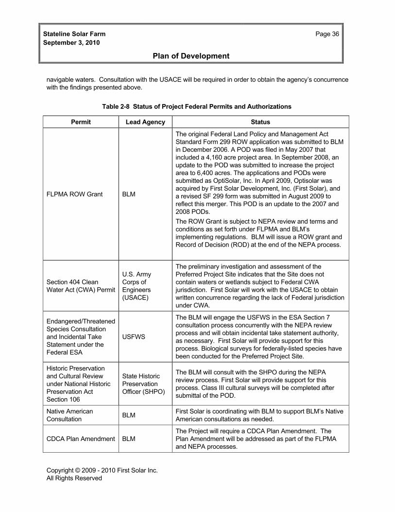
Stateline Solar Farm Page 36September 3, 2010
Plan of Development
Copyright © 2009 - 2010 First Solar Inc. All Rights Reserved
navigable waters. Consultation with the USACE will be required in order to obtain the agency’s concurrence with the findings presented above.
Table 2-8 Status of Project Federal Permits and Authorizations
Permit Lead Agency Status
FLPMA ROW Grant BLM
The original Federal Land Policy and Management Act Standard Form 299 ROW application was submitted to BLM in December 2006. A POD was filed in May 2007 that included a 4,160 acre project area. In September 2008, an update to the POD was submitted to increase the project area to 6,400 acres. The applications and PODs were submitted as OptiSolar, Inc. In April 2009, Optisolar was acquired by First Solar Development, Inc. (First Solar), and a revised SF 299 form was submitted in August 2009 to reflect this merger. This POD is an update to the 2007 and 2008 PODs. The ROW Grant is subject to NEPA review and terms and conditions as set forth under FLPMA and BLM’s implementing regulations. BLM will issue a ROW grant and Record of Decision (ROD) at the end of the NEPA process.
Section 404 Clean Water Act (CWA) Permit
U.S. Army Corps of Engineers (USACE)
The preliminary investigation and assessment of the Preferred Project Site indicates that the Site does not contain waters or wetlands subject to Federal CWA jurisdiction. First Solar will work with the USACE to obtain written concurrence regarding the lack of Federal jurisdiction under CWA.
Endangered/Threatened Species Consultation and Incidental Take Statement under the Federal ESA
USFWS
The BLM will engage the USFWS in the ESA Section 7 consultation process concurrently with the NEPA review process and will obtain incidental take statement authority, as necessary. First Solar will provide support for this process. Biological surveys for federally-listed species have been conducted for the Preferred Project Site.
Historic Preservation and Cultural Review under National Historic Preservation Act Section 106
State Historic Preservation Officer (SHPO)
The BLM will consult with the SHPO during the NEPA review process. First Solar will provide support for this process. Class III cultural surveys will be completed after submittal of the POD.
Native American Consultation BLM First Solar is coordinating with BLM to support BLM’s Native
American consultations as needed.
CDCA Plan Amendment BLM The Project will require a CDCA Plan Amendment. The Plan Amendment will be addressed as part of the FLPMA and NEPA processes.

Stateline Solar Farm Page 37September 3, 2010
Plan of Development
Copyright © 2009 - 2010 First Solar Inc. All Rights Reserved
2.3.2 State Permits and Status Table 2-9 provides a list of the State permits anticipated to be required for the Project, as well as the status of relevant permit applications.
Table 2-9 Status of Project State Permits and Authorizations
Permit Lead Agency Status
Endangered/Threatened Species Take Authorization under California Endangered Species Act (CESA)
CDFG
CESA review and approval will be required for impacts to State-listed species. Focused biological surveys for sensitive species have been conducted for the Solar Farm Site (Appendix G). CDFG is expected to be a full participant in agency discussion between BLM and the USFWS so that CDFG can complete a Consistency Determination with the project BO issued by the USFWS. First Solar will provide input to the agency consultation, as required.
Section 1600-1602 Streambed Alteration Agreement under Fish and Game Code
CDFG
Preliminary assessment indicates that drainage areas located on the Preferred Solar Farm Site are jurisdictional under the Fish and Game Code Sections 1600-1602.First Solar will work with the CDFG to determine extent of jurisdiction pursuant to Fish and Game Code Sections 1600-1602 and to obtain a Streambed Alteration Agreement.
Construction and Operations Phase Storm Water Permits under California Water Code/CWA
California State Water Resources Control Board (SWRCB)
First Solar will be required to prepare SWPPPs incorporating Best Management Practices for storm water management and control, and to file Notices of Intent (NOIs) with the SWRCB.
Section 401 Certification under CWA
Regional Water Quality Control Board (RWQCB)
Section 401 certification would only be required in the event that a USACE Section 404 permit is required, which is not expected based on First Solar’s preliminary investigation and assessment of potential jurisdictional waters and wetlands under the CWA.
Interconnection Agreement CAISO
The Project received a Transition Cluster Phase 2 study in August 2010 and may execute an Interconnection Agreement by the end of 2010.
Fugitive Dust Control Plan
Mojave Desert Air Quality Management District
A fugitive dust control plan will be developed in accordance with Mojave Desert Air Quality Management District requirements prior to construction
An Interconnection Request has been submitted to CAISO, and the Project has been assigned a high position in the CAISO Queue. An Interconnection Feasibility Study, System Impact Study and a Facility Study have been completed for the Project.
The Mojave Desert Air Quality Management District will be consulted before construction and during final Project design regarding fugitive dust emissions and the control of such emissions through adoption of a fugitive dust control plan.

Stateline Solar Farm September 3, 2010
Page 38
Plan of Development
Copyright © 2009 - 2010 First Solar Inc. All Rights Reserved
First Solar hydrologists have completed the initial investigation and assessment of potential waters in the Project Study Area subject to CDFG jurisdiction under the Fish and Game Code. Further assessment is needed to determine if drainage areas located on the Preferred Solar Farm Site are jurisdictional under the Fish and Game Code Sections 1600-1602. First Solar has also avoided major drainages in the design of the Project. If the Project cannot avoid adversely affecting State jurisdictional drainages, a Streambed Alteration Agreement from CDFG would be required and applied for as needed. First Solar has contacted CDFG regarding any potential for State jurisdiction at the Preferred Site.
2.3.3 Local Permits and Status Table 2-10 provides a list and status of the local permits anticipated to be required for the Project, as well as the status of these permit applications.
Table 2-10 Status of Project Local Permits and Authorizations
Permit Lead Agency Status
Sanitation/Septic System Permit
San Bernardino County
Permit will be secured before construction activities commence.
Well Permit San Bernardino County
Permit will be secured before construction activities commence. (Note that a well permit will only be required if new wells are proposed. First Solar has not yet determined if existing wells or new wells will be used)
A permit from San Bernardino County will be required for the septic system for the M&M facility and the well permit, if new wells are required. These permits are typically ministerial actions that are not defined as “projects” under CEQA.
2.4 Financial and Technical Capability First Solar has a very strong liquidity position, benefitting from over $500 million in cash and marketable securities as well as an undrawn $300 million credit facility and negligible debt outstanding ($190 million compared to approximately $875 million of Earnings Before Interest, Taxes, Depreciation, and Amortization). Due to its sound credit profile and financial flexibility, First Solar is currently funding all active projects in the development phase on balance sheets which have totaled over $50 million in 2009 and are forecasted to total in excess of $100 million in 2010. First Solar believes its own balance sheet is the most flexible source of available development capital for its funding requirements.
For construction and term period financing needs of the Project, First Solar intends to solicit debt and equity partners. Over the last year, First Solar has run three successful auctions in the project equity market (focused on strategic equity, private equity, insurance companies, and infrastructure funds), all three of which resulted in secured commitments. In addition, First Solar has started to develop key relationships in the project debt market (bonds, banks, and insurance companies). First Solar’s access to the project debt market is also enhanced by its proven access to the capital market, as it secured a corporate credit facility earlier this year with a syndicate comprised of the leading investment banking institutions.

Stateline Solar Farm Page 39September 3, 2010
Plan of Development
Copyright © 2009 - 2010 First Solar Inc. All Rights Reserved
3.0 Construction of Facilities
The construction of the Project will begin once all applicable approvals and permits have been obtained. It will take approximately 15 months from the commencement of the construction process to complete construction of the Solar Farm and gen-tie line. The following sections provide detail about First Solar’s timeline and process for the construction. Once construction is complete, the Project will be in operation for 30 years.
3.1 Design, Layout, Installation, and Construction Processes First Solar has performed 30 percent engineering design for the Project, as required pursuant to BLM’s POD Guidelines. Appendix B, Site Plan Package, includes detailed 30 percent engineering design plans that depict the design and layout of the Project. The installation and construction processes for the Project are described in the following subsections.
3.2 Construction and Operations Approach – Phased Project Construction of the Project would occur in two basic phases: (i) construction mobilization and (ii) construction and installation of the solar modules, electrical components, and gen-tie line. Construction mobilization includes preconstruction surveys; mobilization of personnel and equipment (including construction of access roads, and installation of trailers, laydown, and materials storage areas); and site preparation. After construction mobilization, construction of the PV arrays and gen-tie line would begin. Construction of the PV arrays is expected to take place at a pace of approximately 1 MW per day after an initial ramp up period. Additional information on the phased approach is provided in Section 3.6.
3.3 Access and Transportation System, Component Delivery, Worker Access Proposed access to the Solar Farm Site would be provided from main gated entrances on Yates Well Road, approximately one mile west of I-15 (see Appendix B Sheet 25). The perimeter of the occupied portions of the Solar Farm Site would be fenced to limit public access. Permanent six-foot tall gated chain-link security fences with barbed wire would be constructed around the solar arrays, the Project Substation and the M&M facility. A traffic study for the Project will be prepared as a part of the NEPA process. Truck traffic would approach the site vicinity via I-15, either from the north or south. From I-15, trucks would proceed west on Yates Well Road to the new access road to the Solar Farm Site entrance.
3.4 Construction Workforce Numbers, Vehicles, Equipment, Timeframes The construction of the Project would begin once all applicable approvals and permits have been obtained and pre-construction surveys have been completed. It would take approximately 15 months from the commencement of the construction process to complete the Project.
Typical construction work schedules are expected to be from 7:00 A.M. to 5:00 P.M., Monday through Friday, which complies with the San Bernardino County noise ordinance restrictions for construction activity of 7:00 AM to 7:00 PM except Sundays or Federal holidays. In the event that construction work takes place outside these typical hours, activities would comply with San Bernardino County standards for noise levels. For safety reasons, certain construction tasks, including final electrical terminations, must be performed after dark when no energy is being produced. The Project would use restricted nighttime task lighting during construction that must occur after sundown. No more lighting would be used than is needed in order to provide a safe workplace, and lights would be focused downward, shielded, and directed toward the interior of the site to minimize light exposure to areas outside the construction area.

Stateline Solar Farm Page 40September 3, 2010
Plan of Development
Copyright © 2009 - 2010 First Solar Inc. All Rights Reserved
During construction, the on-site workforce is expected to average approximately 400 employees, with a peak on-site workforce of approximately 500 employees. The construction workforce would be recruited from within San Bernardino County and elsewhere in the surrounding region as much as practicable.
Most construction equipment/vehicles would be brought to the Solar Farm Site at the beginning of the construction process, and would remain on site throughout the duration of the construction activities for which they are needed; they generally would not be driven on public roads while in use for the Project. Project construction traffic would involve construction worker commuting vehicles, plus periodic truck deliveries of materials and supplies, trash and other offsite truck shipments, and miscellaneous trips by Project staff (e.g., supervisors). Peak vehicular traffic volumes would coincide with the peak of construction employment, which is estimated to be approximately 500 workers. At peak construction, a total of approximately 300 vehicles would make one trip per day to and from the site. Truck traffic during construction is expected to average approximately 30 truck trips per day. However, construction truck deliveries and shipments typically avoid the peak traffic hours in the morning and afternoon, so it is unlikely that they would represent a substantial increase in traffic volumes during the morning and afternoon peak commuting hours.
Table 3-1 lists the type and maximum number of construction/equipment vehicles expected to be in use on the Solar Farm Site during the 15-month construction period.
Table 3-1 Maximum Construction Equipment /Vehicles On Site by Phase
# of Pieces Equipment Purpose Duration (Months)
Site Preparation and Clearing/Grading
10 8,000-Gallon Water Truck Dust Control / Compaction 10 10 Graders Road/Staging Prep 10 10 Tractors with Discs Road/Staging Prep 10 10 10-Ton Rollers Road/Staging Prep 10
Underground Work (boring, trenching, installing conduit) 5 Backhoes or Trenching Machines Excavation/Backfill 15 5 Sheepsfoot Rollers Compaction 15 5 5-Cubic Yard Dump Truck Excavation/Backfill 15
System Installation/Testing
20 4x4 Forklift Material Staging 15
20 ATV Vehicles Material Staging / Transport 15
10 Pick-Up Trucks Material Staging / Transport 15
10 Truck-Mounted/Tracked Pile Drivers Post Installation 15
3.5 Surveying and Staking Surveying includes two main objectives: 1) obtaining detailed topographic information for supporting the storm water modeling and grading design, and 2) construction layout surveying with staking. First Solar is in the process of completing detailed (one-foot interval accuracy) topographic information for the proposed

Stateline Solar Farm Page 41September 3, 2010
Plan of Development
Copyright © 2009 - 2010 First Solar Inc. All Rights Reserved
Solar Farm Site using photogrammetry and field cross sections. Concurrent with the acquisition of topographic data, historic aerial photographs were obtained and analyzed to determine changes in land use and stream channel configurations. The final Site Plans for the Project will be based on the detailed topographic survey of the site that is being performed as a part of the permitting and engineering design process.
Road corridors, buried electrical lines, PV array locations, and the locations of other facilities would be located and staked in order to guide construction activities. Pre-construction survey work would consist of staking and flagging the following: 1) ROW and construction area boundaries, 2) work areas (permanent and short term), 3) cut and fill, 4) access and roads, 5) transmission structure centers, 6) foundation structure, and 7) desert tortoise or endangered plant offsets. Staking and flagging would be maintained until final cleanup. Further pre-construction activities are described in Section 3.6.
3.6 Site Preparation, Clearing, Grading, and Compaction Construction of the Project would be completed in three basic phases: 1) pre-construction activities, 2) site preparation and 3) construction and installation of the solar PV modules and electrical components, including the gen-tie line.
3.6.1 Preconstruction Activities Preconstruction activities would include clearance surveys, fencing, and relocation for desert tortoise; seasonal avoidance of nesting birds; and passive relocation of burrowing owls.
Once these activities occur, First Solar would begin to mobilize for construction. Construction mobilization includes preparing and constructing site access roads, establishing temporary construction trailers and sanitary facilities, and preparing construction staging areas. The Solar Farm Site would include five separate temporary staging areas as discussed in Section 2.2.16, Temporary Construction Facilities. These staging areas would be used in phases throughout the 15-month Project construction period.
3.6.2 Site Preparation Once preconstruction activities are complete, site preparation for the Project would begin. First Solar would use construction grading and compaction techniques that adequately prepare the site for safe and efficient installation and operation of PV arrays. The discussion below provides preliminary detail relative to the site preparation techniques that may be employed at the Project site. First Solar would use the results of the field testing to adjust site preparation and construction methods to minimize impacts to vegetation and facilitate site restoration.
Vegetation Treatment/Clearing and Grading
Vegetation would not be removed from the proposed Project site until the onset of a given construction phase. Within the solar field, plant roadways, and areas around the M&M building, vegetation would be disced under, mulched or composted and retained on site to assist in erosion control and limit waste disposal. In some areas to be graded outside of the solar field, native vegetation may be harvested for replanting to augment soil stabilization.
Areas comprising the solar field would be prepared using conventional farming equipment including tractors with discing equipment and vibratory rollers, with limited use of scrapers to perform micrograding within sections of the solar array field. This method improves construction worker safety by creating a fairly level surface and eliminating trip hazards. The site would be contour graded level; the macro level topography

Stateline Solar Farm Page 42September 3, 2010
Plan of Development
Copyright © 2009 - 2010 First Solar Inc. All Rights Reserved
and stormwater drainage would remain unchanged, but within each solar array ‘high spots” would be graded and the soil cut from these limited areas used to fill ‘low spots’ within the same array.
With this approach, rubber-tired farming tractors towing discing equipment would disc the top 5 to 7 inches of soil. A water truck would follow closely alongside the tractor to moisten the soil to keep dust at or below acceptable levels. The tractor may make several passes to fully disc the vegetation into the top soil, preserving the underground root structure, top soil nutrients and seed base. A drum roller would then be used to flatten the surface and return the soil to a compaction level similar to the preconstruction stage. The intent of the roller is to compact the soil under the solar field area and even out the surface after the discing is complete.
Lastly, limited use of scrapers for micrograding would be employed to only where needed to produce a more level surface than can be produced by the disc and roll technique. Very limited cut and fill would be completed within specific arrays to limit slope to within 3.0% and produce a consistent grade in each solar field area. Approximately 719 acres (39%) of the 1,841-acre graded area would use the cut and fill grading method. Hydrology analysis would evaluate the areas that are susceptible to scour from storm water runoff. The ground would be graded to a level topography using micrograding only where necessary.
Vegetation would be cleared from roadways, access ways, and where concrete foundations are used for inverter equipment, substations, and the O&M facilities. Vegetation would be cleared for construction of the drainage controls, including berms. Organic matter would be mulched and redistributed within the construction area (except in trenches and under equipment foundations). Plant root systems would be left in place to provide soil stability except where grading and trenching are required for placement of solar module foundations, underground electric lines, inverter and transformer pads, road and access ways, and other facilities.
Compaction
The construction process would require moving some heavy equipment across the site, including delivery trucks, pile driving equipment, and cranes. Soil would be compacted to a level that allows this equipment to move across the site. The compaction would be a maximum of 90 percent across the site. First Solar is performing field testing to determine if a lower compaction level would meet construction requirements and what levels of compaction are compatible with post-construction revegetation.
Site preparation would also require improvement of approximately 149.5 miles of aggregate or gravel based road to access different areas of the Project (see Sheet 25, Appendix B). These roads would be treated with road stabilization material, as needed. Further detail relative to the site access road construction is provided in Section 3.8, Gravel, Aggregate and Concrete Needs and Sources. These roads would be heavily used during construction and would be rarely used during operations. Detail showing a section of the planned access road improvement material is provided on Sheet 25, Appendix B, Preliminary Access Road Plan.
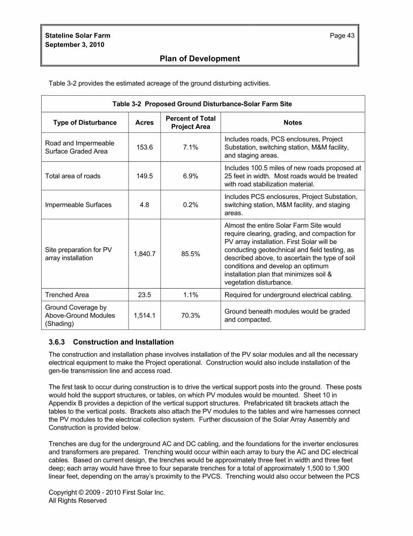
Stateline Solar Farm Page 43September 3, 2010
Plan of Development
Copyright © 2009 - 2010 First Solar Inc. All Rights Reserved
Table 3-2 provides the estimated acreage of the ground disturbing activities.
Table 3-2 Proposed Ground Disturbance-Solar Farm Site
Type of Disturbance Acres Percent of Total Project Area Notes
Road and Impermeable Surface Graded Area 153.6 7.1%
Includes roads, PCS enclosures, Project Substation, switching station, M&M facility, and staging areas.
Total area of roads 149.5 6.9% Includes 100.5 miles of new roads proposed at 25 feet in width. Most roads would be treated with road stabilization material.
Impermeable Surfaces 4.8 0.2% Includes PCS enclosures, Project Substation, switching station, M&M facility, and staging areas.
Site preparation for PV array installation 1,840.7 85.5%
Almost the entire Solar Farm Site would require clearing, grading, and compaction for PV array installation. First Solar will be conducting geotechnical and field testing, as described above, to ascertain the type of soil conditions and develop an optimum installation plan that minimizes soil & vegetation disturbance.
Trenched Area 23.5 1.1% Required for underground electrical cabling.
Ground Coverage by Above-Ground Modules (Shading)
1,514.1 70.3% Ground beneath modules would be graded and compacted.
3.6.3 Construction and Installation The construction and installation phase involves installation of the PV solar modules and all the necessary electrical equipment to make the Project operational. Construction would also include installation of the gen-tie transmission line and access road.
The first task to occur during construction is to drive the vertical support posts into the ground. These posts would hold the support structures, or tables, on which PV modules would be mounted. Sheet 10 in Appendix B provides a depiction of the vertical support structures. Prefabricated tilt brackets attach the tables to the vertical posts. Brackets also attach the PV modules to the tables and wire harnesses connect the PV modules to the electrical collection system. Further discussion of the Solar Array Assembly and Construction is provided below.
Trenches are dug for the underground AC and DC cabling, and the foundations for the inverter enclosures and transformers are prepared. Trenching would occur within each array to bury the AC and DC electrical cables. Based on current design, the trenches would be approximately three feet in width and three feet deep; each array would have three to four separate trenches for a total of approximately 1,500 to 1,900 linear feet, depending on the array’s proximity to the PVCS. Trenching would also occur between the PCS
Stateline Solar Farm Page 44September 3, 2010
Plan of Development
Copyright © 2009 - 2010 First Solar Inc. All Rights Reserved
and transformer locations. It is expected that trenching would disturb 23.5 acres, approximately 1 percent of the Solar Farm Site. The trenched areas would be backfilled filled once the cables are buried and previous contours restored.
Electrical cables are laid in the trenches and combiner boxes are also installed. Underground cables connect the PCSs to the on-site AC electric infrastructure, and also connect the PCS to the PVCS. Overhead lines connect the electrical output from the PVCS to the onsite Project Substation.
It is expected that separate construction crews would build the Project Substation and the gen-tie line. During the final system validation and commissioning process, the DAS and monitoring systems would be brought online, the equipment tested, and operational readiness verified. Once commissioning is complete the Project would be brought online and connected to the grid.
3.7 Solar Array Assembly and Construction PV modules and module framing assemblies would arrive at the construction staging area in containers on tractor-trailers. The tractor-trailers would utilize the gravel access roads to deliver the modules and the framing assemblies to the array areas. PV modules and the assemblies would be lifted from the tractor-trailers and placed adjacent to the array locations.
Vertical steel support piles spaced approximately 10 feet apart center-to-center are driven into the ground to an approximate depth of 3 to 7 feet below grade. The module framing assemblies, or tables, are then attached to the support posts using tilt brackets. The PV modules would be manually secured to the tables as depicted in Appendix B, Sheet 10. Wiring harnesses electrically connect several rows of tables to a combiner box that would deliver power to an inverter in the PCS.
The PCS enclosures are prefabricated concrete structures mounted on prefabricated foundations or vaults. They would be installed at predetermined central locations within each array and then connected to incoming lines from the combiner boxes. After the blocks are installed in a particular area, traffic is expected to be limited to infrequent low-impact traffic in the aisle ways between PV blocks for inspection, maintenance, and repair purposes.
3.8 Gravel, Aggregate, and Concrete Needs and Sources Prior to construction, approximately 149.5 miles of site access roads would be stabilized with gravel, aggregate or other road stabilization material, such as geotextile fabric. The stabilization materials would be obtained locally to the extent possible. Concrete would be used to create foundations and pads for the Project Substation equipment and the M&M facility. Inverter enclosures and transformers are placed on poured or pre-cast concrete foundations/vaults.
The total volume of gravel, aggregate, and concrete to be used for the Project is estimated as follows:
Portland Cement Concrete (PCC) (pre-cast) = 6,200 cubic yards
Class II Aggregate Base (for pads) = 1,250 cubic yards
Class II Aggregate for Gravel Base Road (8 inches thick) = 10,800 cubic yards
3.9 Solar Module and Electrical Construction Activities Groups of glass PV modules are installed onto the tables as described in Sections 2.2.10 and 3.7, and are wired to the PCS using wiring harnesses with touch-safe connectors. Modules are transported from shipping

Stateline Solar Farm Page 45September 3, 2010
Plan of Development
Copyright © 2009 - 2010 First Solar Inc. All Rights Reserved
containers to the location of install. They are placed on the tables and fastened with brackets at the top and bottom of the module.
Once all the modules are installed in an array, they can be electrically connected. The modules are built with standard touch-safe wiring connectors. Workers walk behind each row and plug the wires from each module into a wiring harness that collects all power from each table.
An electrician connects all wiring harness to a combiner box. Each combiner box links the connections from the PV modules. All combiner boxes are wired via underground DC cables to the PCS enclosure. An electrician connects these wires to the inverters and other electrical equipment inside the PCS enclosure. Each inverter converts the DC power to three-phase AC power, which is fed into a step-up transformer.
Transformers are connected via underground AC cables to the Photovoltaic Combining Switchgear (PVCS). Each PVCS combines the power output from multiple arrays. Power is then transferred to overhead lines which route all power to the Project Substation. The Project Substation would step the power up to 220 kV for transmission via the 220-kV gen-tie line to the Ivanpah Substation.
Certified electricians in the construction workforce would perform appropriate Project electrical construction activities starting with combiner box connections. Utility journeymen may be required to perform or supervise the higher-voltage electrical construction activities for the Project Substation and gen-tie line.
3.10 Aviation Lighting (Power Towers, Transmission) This section is not applicable because there would be no Project facilities, or related facilities, above the height regulated by the Federal Aviation Administration. The nearest airport to the Project site is Jean Airport, about 20 miles north of the project site in Jean, Nevada. McCarran International Airport is located approximately 45 miles northeast of the site in Las Vegas, Nevada. The closest airport in San Bernardino County is the Barstow-Daggett Airport, approximately 100 miles south of the Project site. A new commercial airport, the Ivanpah Valley Airport, has been proposed between Jean and Primm, Nevada and would be approximately 5 miles north of the Project site.
The Solar Farm itself is a low-profile facility; the arrays are less than approximately five feet tall and the M&M facility is approximately 19 feet tall. Project transmission structures would be less than 200 feet tall and would not require lighting, avoiding potential interference with aviation. There is essentially no potential for light interference from the solar arrays to local aviation: the PV modules used in the installation are black and absorb over 90 percent of the light received; as a result, glare from reflected sunlight is not an issue. These type of PV modules have been installed at numerous airports, including Denver International Airport and Nellis Air Force Base, and studies have found that the reflection from PV array installations do not cause problems for airplanes in the vicinity of the solar farms.
3.11 Site Stabilization, Protection, and Reclamation Practices Before Project construction begins, First Solar would determine the appropriate site stabilization measures to be utilized on the Project. A more detailed geotechnical study is planned to support detailed project design, and this study will provide valuable input with respect to soil conditions and needed stabilization measures
After Project construction relatively minimal amounts of operations and maintenance activities are required during operations. Access roads and aisle ways would need to be maintained, but the project areas covered by panels can support revegetation. Therefore, First Solar is exploring options to foster revegetation of the

Stateline Solar Farm Page 46September 3, 2010
Plan of Development
Copyright © 2009 - 2010 First Solar Inc. All Rights Reserved
Solar Farm Site post-construction. As described above, First Solar is planning to perform field tests of site preparation, revegetaion, and restoration techniques in an environment similar to the Project Site. First Solar has previously implemented similar field tests at a non-desert site to explore options for vegetation treatment and restoration. The test program would examine vegetation removal techniques, stabilization during construction, and revegetation during and after construction.
At the end of the Project’s useful life, First Solar would decommission and completely remove the PV arrays and supporting electrical and facility systems. Following facility decommissioning and removal, the area would be reclaimed according to applicable regulations at the time of decomissioning. Please see Section 7.3.8 for a discussion of the facility decommissioning plans.

Stateline Solar Farm Page 47September 3, 2010
Plan of Development
Copyright © 2009 - 2010 First Solar Inc. All Rights Reserved
4.0 Related Facilities and Systems
4.1 Transmission System Interconnect The Project would interconnect with the proposed 220 kV El Dorado-Ivanpah transmission system, which would replace the existing 115 kV transmission line, via the future SCE Ivanpah Substation, which would be located 2.3 miles southwest of the Solar Farm Site. SCE estimates that the El Dorado-Ivanpah transmission system project, including the Ivanpah Substation, will be completed by July 2013.
4.1.1 Existing Transmission System The primary transmission system of adequate capacity to accept the proposed solar farm output, which is located in the vicinity of the proposed Project, is the El Dorado-Ivanpah transmission line which is proposed to upgrade the existing 115 kV transmission line. This upgrade is proposed initially from the Mountain Pass Substation, about 20 miles southwest of the Project, to the El Dorado Substation, located approximately 35 miles northeast of the Project. In the area near the Project site the Transmission Corridor runs southwest/northeast through the Project site.
The El Dorado-Ivanpah upgrade project is currently undergoing detailed, separate, environmental review with SCE as the project applicant and the California Public Utilities Commission as the Lead Agency. Other CAISO/SCE system upgrades are expected to also occur in the next decade to serve the larger Pisgah to Marketplace El Dorado transmission corridors, running roughly along the I-15 corridor to the California-Nevada state boundary and then on to the Marketplace/El Dorado substations. These upgrades would also serve to provide transmission capability to later stages of the Project. Additional information on these system upgrades will become available later in the EIS process as the Interconnection Study Process moves forward as dictated by the CAISO.
4.1.2 Proposed Transmission System The medium-voltage collection system lines (34.5 kV) transmitting power from each PV block would be buried underground from the PCS to the PVCS and would be connected on overhead lines from the PVCS to the on-site Project Substation. At the Project Substation, the Project’s output would be stepped up to the existing or proposed transmission system’s voltage of 220kV.
First Solar is considering several different options of transmission structure to support new gen-tie construction including single or double circuit, galvanized or painted, Lattice Steel Tower (LST) or tubular steel pole (TSP) structures. LST are a common type of transmission structure used in high-voltage transmission line applications. An LST is a freestanding steel framework that has been used to support transmission lines throughout the nation. The use of LST offers several advantages as compared to other structure types. Primarily, LST have low maintenance costs and adequate strength-to-weight ratios. High quality, hot-dipped galvanizing of structural members and fasteners assures long-term integrity, reliability, and low maintenance. Because LST have a well-earned reputation for dependability, they are the most likely structure to be used for proposed Project construction.
TSPs are steel poles manufactured in long sections, which taper in cross-sections from the base of the pole to top of the pole. The use of TSP can offer an advantage over LST in certain types of applications, such as locations where ROW width is constrained or space for structure installation is limited. TSP require large footings and are manufactured in long sections requiring use of long-bed trucks for transportation and heavy cranes that can lift and stack the TSP sections for assembly.

Stateline Solar Farm Page 48September 3, 2010
Plan of Development
Copyright © 2009 - 2010 First Solar Inc. All Rights Reserved
The transmission of the stepped up 220 kV power produced by the Project would use overhead construction. Under this method of construction, transmission conductor would be strung overhead on the supporting transmission structures. Heights of structures for the Project would vary widely depending on the electrical clearances required but would be less than 200 feet in all cases.
4.1.3 Ancillary Facilities and Substations Other than the gen-tie line, described in Section 4.1.2, and the ancillary facilities for the Solar Farm Site described in Section 2.2, there are no further ancillary facilities necessary for the Project.
The proposed Ivanpah Substation will be constructed, owned, operated, and maintained by SCE and will be evaluated by the CPUC. It is not part of this project.
4.1.4 Status of Power Purchase Agreements (PPAs) A Power Purchase Agreement for 300 MW was executed with SCE on August 17, 2009. On October 16, 2009, SCE submitted Advice Letter 2391-E requesting that the CPUC issue a resolution approving the Stateline Contract. The CPUC’s Energy Division is reviewing the advice letter and is in the process of drafting a resolution for the CPUC’s approval of the contract. The resolution is scheduled for the September 2, 2010 CPUC agenda.
4.1.5 General Design and Construction Standards The specific engineering design for the above described facilities will be negotiated between First Solar, SCE, and CAISO once the Final Facilities Studies are complete. The Project will comply with San Bernardino County, State of California, and International Building Codes. Additionally, the Project will be designed in conformance with the National Electrical Code.
4.2 Gas Supply Systems The Project would not use natural gas for power production.
4.3 Other Related Systems 4.3.1 Communications System Requirements For transmission of operational data and to support employees working on site, First Solar expects to utilize existing wired or wireless telecommunications facilities. In the event that these facilities are not available in the Project vicinity, First Solar would supplement with small aperture (less than one meter) satellite communications gear.
In addition, the Solar Farm Site would be routinely patrolled by pickup trucks and all-terrain vehicles. These vehicles would be operated by supervisors and foremen and equipped with communications devices (cell phones and/or radios) to coordinate any emergency or fire-fighting issues internally and with the local fire department.
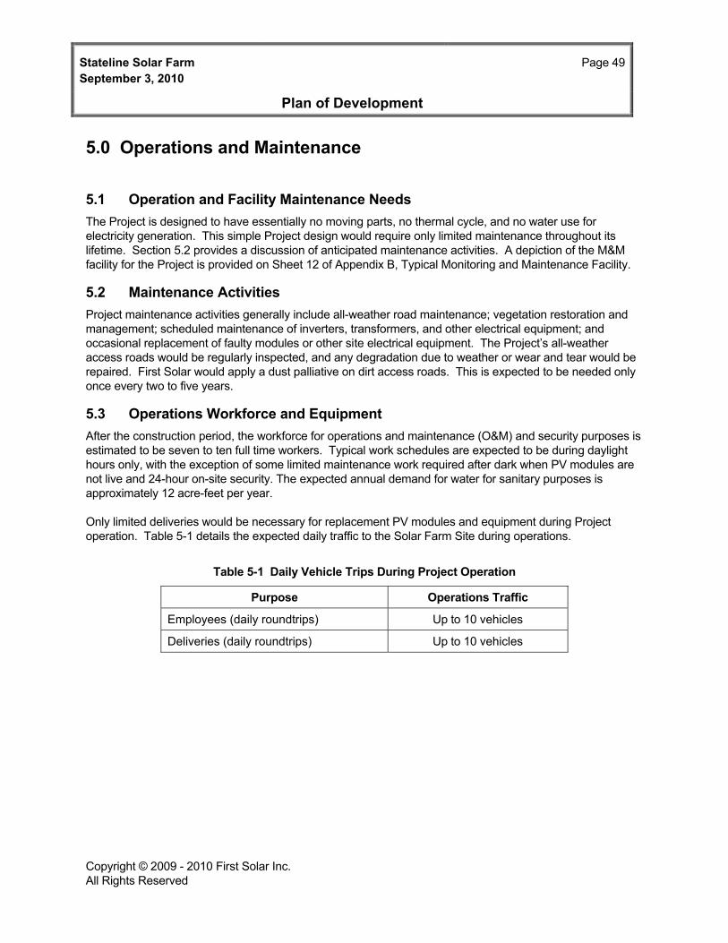
Stateline Solar Farm Page 49September 3, 2010
Plan of Development
Copyright © 2009 - 2010 First Solar Inc. All Rights Reserved
5.0 Operations and Maintenance
5.1 Operation and Facility Maintenance Needs The Project is designed to have essentially no moving parts, no thermal cycle, and no water use for electricity generation. This simple Project design would require only limited maintenance throughout its lifetime. Section 5.2 provides a discussion of anticipated maintenance activities. A depiction of the M&M facility for the Project is provided on Sheet 12 of Appendix B, Typical Monitoring and Maintenance Facility.
5.2 Maintenance Activities Project maintenance activities generally include all-weather road maintenance; vegetation restoration and management; scheduled maintenance of inverters, transformers, and other electrical equipment; and occasional replacement of faulty modules or other site electrical equipment. The Project’s all-weather access roads would be regularly inspected, and any degradation due to weather or wear and tear would be repaired. First Solar would apply a dust palliative on dirt access roads. This is expected to be needed only once every two to five years.
5.3 Operations Workforce and Equipment After the construction period, the workforce for operations and maintenance (O&M) and security purposes is estimated to be seven to ten full time workers. Typical work schedules are expected to be during daylight hours only, with the exception of some limited maintenance work required after dark when PV modules are not live and 24-hour on-site security. The expected annual demand for water for sanitary purposes is approximately 12 acre-feet per year.
Only limited deliveries would be necessary for replacement PV modules and equipment during Project operation. Table 5-1 details the expected daily traffic to the Solar Farm Site during operations.
Table 5-1 Daily Vehicle Trips During Project Operation
Purpose Operations Traffic
Employees (daily roundtrips) Up to 10 vehicles
Deliveries (daily roundtrips) Up to 10 vehicles

Stateline Solar Farm Page 50September 3, 2010
Plan of Development
Copyright © 2009 - 2010 First Solar Inc. All Rights Reserved
THIS PAGE INTENTIONALLY LEFT BLANK

Stateline Solar Farm Page 51September 3, 2010
Plan of Development
Copyright © 2009 - 2010 First Solar Inc. All Rights Reserved
6.0 Environmental Considerations
Environmental considerations have been summarized for the Project in Appendix E, Environmental Considerations Table. This table provides a list of the potential environmental impacts of the Project as well as environmental protection and mitigation measures that are proposed to avoid and reduce the Project’s impacts. In addition to the environmental protection measures identified in Appendix E, the Project would adopt the applicable desert tortoise protection measures prescribed by the NEMO Plan, and applicable measures adapted to the Project from the BMPs and mitigation measures prescribed for renewable energy projects on public land.

Stateline Solar Farm September 3, 2010
Page 52
Plan of Development
Copyright © 2009 - 2010 First Solar Inc. All Rights Reserved
THIS PAGE INTENTIONALLY LEFT BLANK

Stateline Solar Farm Page 53September 3, 2010
Plan of Development
Copyright © 2009 - 2010 First Solar Inc. All Rights Reserved
7.0 Supplemental Information
First Solar understands that supplemental information will be required from the Applicant to prepare the NEPA analysis and complete the review process, although it is not required to be submitted with the POD. Some of this information has already been developed and is readily available, and First Solar is summarizing this information below. Additional data will be developed and provided in the future, as more information is obtained during the Project design development phase.
7.1 Engineering and Civil Design 7.1.1 Facility Survey and Design Drawing Standards The Project would comply with applicable survey, inspection, and design drawing codes and standards as designated by the State of California, the Federal government, and International Building Codes. First Solar is a leader in the development of large-scale solar energy systems and, as such, has technical expertise in conducting facility surveys and preparing drawings and sketches using AutoCAD based on appropriate engineering specifications, design criteria and technical manuals. First Solar ensures conformance with applicable codes and standards as well as company policies and procedures and conforms to appropriate CAD, ANSI, and ISO drafting standards in both 2D and 3D formats.
7.1.2 Final Engineering and Civil Design Packages First Solar has developed 30 percent engineering and civil designs, which are included as part of the SPP included in this POD as Appendix B. The engineering and civil designs will be updated during development of the Project and will be finalized during EIS development prior to Project construction.
7.1.3 Watershed and Drainage Analysis and Calculations As described in Section 2.2.4, a hydrologic and hydraulics study is included in Appendix H. The hydrological study includes evaluation of the watershed and site drainage as well as surface water impacts.
7.1.4 Watershed Protection and Erosion Control Drawings Based on the results of the modeling analysis described above, First Solar has provided grading and erosion control drawings submitted as Sheets 19 through 24 in Appendix B. These include the Preliminary Grading and Compaction Plans (Sheets 19 through 22), Proposed Erosion Control Plan (Sheet 23) and Preliminary Erosion Control Details (Sheet 24).
7.1.5 Final Site Grading Plans First Solar has developed 30 percent design grading and erosion control plans and details, which are included in this POD as Sheets 19 through 24 in Appendix B. These Site Grading Plans will be updated during development of the Project and will be finalized during EIS development and prior to Project construction.
7.2 Alternatives Considered by the Applicant 7.2.1 Alternative Site Evaluation Criteria NEPA regulations (40 C.F.R. § 1502.14 [c]) identify the need to consider reasonable alternatives. NEPA requires consideration of all aspects that may be relevant and important to decision-makers, including factors that are not related to environmental quality. NEPA requires substantial treatment of each

Stateline Solar Farm Page 54September 3, 2010
Plan of Development
Copyright © 2009 - 2010 First Solar Inc. All Rights Reserved
alternative, including the proposed action, so that reviewers may evaluate their comparative merits (40 CFR Section 1502.14). The process of evaluating and selecting a suitable site for the Stateline involved application of a number of specific criteria.
First Solar’s evaluation criteria included the following:
High levels of solar insolation, as well as a contiguous area with reasonably flat topography that is large enough (several thousand acres minimum) for at least 300 MW of PV facilities;
Avoid areas that are highly pristine or biologically sensitive, such as an ACEC, DWMA, designated wilderness areas, National Park, etc. The site also should not be within a military facility;
Avoid high quality (Category I or II) desert tortoise habitat, or important habitat for other sensitive species or habitats (washes);
Near existing high voltage transmission facilities (220 kV or higher) with sufficient capacity for Project output and with suitable interconnection locations;
Good highway access and available for sale or lease/ROW at a reasonable cost; and
Located in an area that has a history of development including transmission and road infrastructure and nearby industrial facilities.
7.2.2 Alternatives Considered but not Carried Forward by Proponent First Solar has considered alternative sites within the proposed Project Study Area for siting of the main Project generation facilities, the onsite Project substation, and the gen-tie line. The Preferred Project Alternative includes both the preferred Solar Farm Site, the preferred gen-tie-line transmission route, and preferred access corridor and is described in this Plan of Development. First Solar understands that the alternative siting for the Project facilities and transmission routes within the proposed Project Study Area will be analyzed during the NEPA process and is prepared to provide detail relative to these alternatives during that process as well as provide the necessary data to the EIS contractor to perform a sufficient level of analysis for the reasonable range of alternatives.
If an alternative was identified that clearly does not have the potential to provide an overall environmental advantage as compared to the Proposed Project, it was eliminated from further consideration. Several alternatives for siting of the Project components were considered, but not carried forward due to various constraints. These include the following:
Alternative Site Locations Along the Ivanpah-El Dorado Transmission Line (Public Land)
Because the southern California desert is an area of high solar insolation, developing a solar project in this area is highly desirable. However, much of the land in this area is precluded or restricted from development, including areas set aside as DWMAs, ACECs, National Parks, and National Wilderness areas. Areas available for development outside of these conservation lands are further limited because of existing or proposed ROW for other energy projects, almost all of which are renewable energy projects (solar or wind). Several different locations for the Project were considered. Due to the availability of land, sensitivity of the environmental resources (as discussed above), or the availability of existing interconnection capacity, these alternatives were not considered viable.

Stateline Solar Farm Page 55September 3, 2010
Plan of Development
Copyright © 2009 - 2010 First Solar Inc. All Rights Reserved
Alternative Site Locations Along the Ivanpah-El Dorado Transmission Line (Private Land)
Private land was considered as an alternative to the proposed Project Study Area. However, the potential use of private land was limited by the absence of contiguous parcels as well as the feasibility and timing of reaching agreements for site control on sufficient private parcels to accommodate the proposed Project. Thus, private land alternatives were eliminated for consideration in siting the proposed Project.
Alternative Site Configurations Placing PV Arrays Within Desert Washes
First Solar considered an alternative that would place all of the arrays within the southern portion of the project site to avoid most of the desert tortoise population concentrations. This alternative would require construction of PV arrays within the two desert washes present on the southern portion of the site. This alternative was not carried forward for the following reasons:
1) I-Beam Column Depths That Are Extreme and Variable. I-beam column depths of up to 9 feet would be required to accommodate anticipated worst-case scour. It needs to be noted that this depth of embedment likely exceeds the maximum that is constructible. The nearby Bright Source project has recently failed to drive thinner columns successfully below 48 inches.
2) Increased Depth for Buried Cables. Cable would need to be buried at 5 feet in certain locations, instead of 30 inches, to get below the depth of scour.
3) Difficulties in Maintaining the Power Facilities After Scour. A significant storm event would remove material from ravine areas throughout the site. Soil removal of over 4 feet may occur in places within the desert washes. This would lead to compromised or failed steel support structures, exposed or failed direct burial cable, and washed out access roads. In order to make repairs to scoured areas, soil would likely have to be ‘replaced’. There could be areas of scour that are substantially long and deep (a quarter mile in length, 10 feet in width and a couple of feet deep). This poses a severe complication to project operations and maintenance. The soil would either have to be placed back by hand due to the tightness of the arrays (mechanical equipment cannot access portions of the arrays), or the new lower terrain would have to be accommodated by increasing new support foundations and lowering direct burial cable. The washed out areas, it needs to be noted, would have increased access complications if the latter is chosen.
7.2.3 Alternative Site Configurations to be Analyzed During NEPA Construction may be limited because of the hydrologic conditions, biological resources, and cultural resources present at the site. These issues have been and are currently being studied and are driving the preferred siting of the Project components within the Project Study Area. Alternatives within the Project Study Area will be evaluated during the NEPA process.
Solar Farm Site
As discussed throughout the POD, First Solar has identified a Project Study Area (5,454 acres) that is considerably larger than would be needed for the Project facilities themselves (the Preferred Solar Farm Site and Access Road is 2,114 acres). This provides flexibility to configure the Project in a manner that is technically and operationally sound and also minimizes the potential for impacts on site environmental and other resources. As discussed earlier, biological surveys identified areas of particular environmental sensitivity in terms of sensitive species. Also, washes in the southern portion of the Project Study Area were avoided. There are a variety of possible layouts for an approximately 2,200-acre facility within a 5,454-acre area. First Solar has identified two layout alternatives (Alternatives A and C) for the solar farm (Appendices A and C). Alternative A places all project components (except the Transmission Corridor and

Stateline Solar Farm Page 56September 3, 2010
Plan of Development
Copyright © 2009 - 2010 First Solar Inc. All Rights Reserved
Access Corridor) north of the large wash located in Sections 25 and 26. However, this alternative pushes the Solar Farm Site further to the west, where populations of desert tortoise were observed. Alternative C was presented as the Preferred Alternative in the April POD. This alternative moves the facilities south within the Project Study Area, avoiding more areas of desert tortoise population than the Preferred Alternative. However, this alternative uses approximately 3,011 acres, 838 acres more than the Preferred Project, because the facilities must be spread out to avoid the two large washes in the southern portion of the Project Study Area. The NEPA process will further evaluate Project sites/configurations within the Project Study Area.
Transmission Corridor Alternatives
While the gen-tie alignment may be shifted slightly, the location of the Ivanpah Substation, where the Project would interconnect, has already been selected by SCE and limits the alternatives to the Transmission Corridor. First Solar is considering several different options of transmission structure to support new gen-tie construction including single or double circuit, galvanized or painted, Lattice Steel Tower or tubular steel pole structures, as discussed in Section 4.1.2.
7.2.4 Comparison of Alternative Site Configurations The components of Alternative B (Preferred Alternative, see Appendix B) and Alternatives A and C (see Appendices A and C) are summarized in Table 7-1.
7.3 Facility Management Plans 7.3.1 Storm Water Pollution Prevention and Protection Plan Because the Project would disturb more than one acre of land, Storm Water Pollution Prevention Plan (SWPPP) would be required for Project construction. The SWPPP would identify structural and non-structural Best Management Practices (BMPs) to manage the offsite discharge of storm water from the Solar Farm site. Structural BMPs are devices such as de-silting basins or swales; non-structural BMPs refer to operating practices on the site, such as covering and storing potential pollutant source materials in a manner that avoid discharges to the storm water system. A Post-Construction Storm Water Management Plan (i.e., a Site Runoff Control plan composed of structural and non-structural BMPs) will be prepared.

Stateline Solar Farm Page 57September 3, 2010
Plan of Development
Copyright © 2009 - 2010 First Solar Inc. All Rights Reserved
Table 7-1 Comparison of Alternative Site Configurations
Alternative A Alternative B
(Preferred Alternative) Alternative C
Project Facility or Component
Number of Components within Project
Approx. Area
(acres)
Percent of Total
Preferred Project
Site1
Approx. Area (acres)
Percent of Total
Preferred Project Site2
Approx. Area (acres)
Percent of Total
Preferred Project Site3
Solar Farm Site (includes Access Corridor)
NA 2,031 96.7% 2,114 98.2% 2,986 99.2%
Transmission Corridor
One transmission line and
associated transmission
towers
47 2.3% 38 1.8% 24 0.8%
PV Arrays NA 877.3 42.2% 863.0 40.1% 754.3 25.1%
On-site Project Substation
1 2.5 <0.1% 2.5 <0.1% 2.5 <0.1%
M&M facility 1 0.6 <0.1% 0.6 <0.1% 0.6 <0.1%
Temporary Construction Staging Areas
5 29.7 1.4% 29.7 1.4% 37.6 1.2%
Access Roads (Including Site Access Road)
59.2 miles (Alt A)
57.4 miles (Alt B)
108.1 miles (Alt C)
154.9 7.5% 149.5 6.9% 274.4 9.1%
Graded Area Including Roads
NA 1,933.4 93.0% 1,846.0 85.7% 2,305.2 76.6%
Area Disturbed by Trenching
NA 25.3 1.2% 23.5 1.1% 30.9 1.0%
Area Covered by At-Grade Items (inverter pads, substation, M&M facility)
NA 4.2 0.2% 4.1 0.2% 4.9 0.2%
Area Covered/ Shaded by Above-Grade Modules
NA 1,539.5 74.1% 1,514.1 70.4 1,625.4 54.0%
Security Fencing NA 7.4 miles NA 7.6 miles NA 14.4 miles NA

Stateline Solar Farm Page 58September 3, 2010
Plan of Development
Copyright © 2009 - 2010 First Solar Inc. All Rights Reserved
Table 7-1, Continued Notes:
Numbers may not add to 100% due to rounding.
NA = Not Applicable 1 The Preferred Project Site for Alternative A is 2,078 acres, which includes 2,031 acres for the Preferred Solar Farm Site and Access Corridor and 47 acres for the Transmission Corridor 2 The Preferred Project Site for Alternative B is 2,153 acres, which includes 2,114 acres for the Preferred Solar Farm Site and Access Corridor and 38 acres for the Transmission Corridor 3 The Preferred Project Site for Alternative C is 3,011 acres, which includes 2,986 acres for the Preferred Solar Farm Site and Access Corridor and 24 acres for the Transmission Corridor.
7.3.2 Hazardous Materials Management Plan Several methods would be used to properly manage and dispose of hazardous materials, petroleum products and hazardous wastes. Waste lubricating oil would be recovered and recycled by a waste oil recycling contractor. Chemicals would be stored in appropriate chemical storage facilities. Bulk chemicals are not expected to be used on site. Most other chemicals would be stored in smaller returnable delivery containers. All chemical storage areas would be designed to contain leaks and spills in containment areas or containment plans. A more detailed hazardous waste management plan indicating types, quantities, storage and management procedures, etc., will be prepared by First Solar for use in the Draft EIS.
7.3.3 Spill Prevention Control and Countermeasure Plan First Solar will prepare a Spill Prevention Control and Countermeasure (SPCC) Plan due to the presence on the site of oil-containing transformers.
7.3.4 Waste Management Plan All construction operational wastes produced at the Project site would be properly collected, recycled (if possible), treated (if necessary), and disposed of in an appropriate manner and in full compliance with all regulatory requirements. Project wastes would include sanitary wastewater, nonhazardous waste, and potentially small quantities of hazardous waste, primarily liquid. Domestic waste streams such as showers and toilets would be treated using a septic tank and leach field. Heavy solids would settle to the bottom of the septic tank to undergo anaerobic decomposition and slight compaction, and would be removed, as necessary. Liquid effluent from the septic tanks would be distributed to a leach field. It is expected that the leach field would satisfy the needs of the Project for its entire service life. The leach field would be constructed of open tile drains laid in trenches filled with gravel or crushed stone. The trenches permit downward percolation or upward evaporation and transpiration. Additional data on Project waste streams (quantities, types, storage, handling, and disposal procedures, etc.) will be prepared by First Solar for use in the Draft EIS.
7.3.5 Integrated Weed Management Plan Noxious weed control practices for the Stateline Solar Farm have been developed from existing Integrated Weed Management Plans contained in other PODs for Arizona, Nevada and California. First Solar will coordinate with the BLM, the CDFG and other jurisdictional agencies to identify target weed species for the Project. In addition, First Solar will coordinate with Caltrans to ensure that noxious weed controls for the Project area are in conformance with road management plans.

Stateline Solar Farm Page 59September 3, 2010
Plan of Development
Copyright © 2009 - 2010 First Solar Inc. All Rights Reserved
7.3.6 Health and Safety Plan The Project would follow OSHA and CalOSHA requirements in its construction and operating activities. A safety and compliance director would be assigned to the Project to ensure that safety is given the highest priority. A site-specific Health and Safety Plan would be developed, identifying the roles and responsibilities of every employee with respect to safety on the Project.
7.3.7 Environmental Inspection and Compliance Monitoring Plan First Solar would develop an Environmental Inspection and Compliance Monitoring program and plan for the Stateline Solar Farm, covering both construction and operation. A qualified individual would be designated to serve as the Project’s Environmental Manager. The Environmental Manager would be responsible for development and implementation of the Project’s compliance program. They would be responsible for communication and coordination with the applicable regulatory agencies and ensuring compliance with the various conditions and requirements of the full range of Project permits and approvals. The Environmental Manager would be responsible for the necessary record keeping and reporting required by Project permits. They would ensure that all applicable plans are up to date (e.g., Project Spill Prevention Control and Countermeasure [SPCC] Plan. The Environmental Manager’s role would include advising Project management of actual and potential compliance/non-compliance issues and for ensuring that Project planning takes appropriate account of compliance issues in advance.
7.3.8 Facility Decommissioning The Project has a minimum expected lifetime of 30 years. When the Project concludes operations, much of the wire, steel, and modules of which the system is comprised would be recycled to the extent feasible. The Project components would be deconstructed and recycled or disposed of safely, and the Solar Farm Site could be converted to other uses in accordance with applicable land use regulations in effect at the time of closure. Consistent with BLM and NEPA requirements, a detailed Decommissioning and Reclamation Plan (Decommissioning Plan) will be developed in a manner that both protects public health and safety and is environmentally acceptable.
Reclamation and Site Stabilization Planning
Conditions are likely to change over the course of a Project lifespan 30 years, and a final Decommissioning Plan will be developed in the future prior to facility closure based on conditions as they occur at that time. The reclamation measures provided in the Decommissioning Plan will be developed to ensure protection of the environment and public health and safety and to comply with applicable laws, ordinances, regulations, and standards.
In general, the Project Decommissioning Plan will address:
Proposed decommissioning and reclamation measures for the Project and associated facilities;
Activities necessary for site restoration/re-vegetation, if removal of equipment and facilities is needed;
Procedures for reuse, recycling, or disposal of facility components; collection and disposal of hazardous wastes; and use or disposal of unused chemicals;
Costs associated with the planned decommissioning activities and the source of funding for these activities; and
Conformance with applicable laws, ordinances, regulations, and standards.

Stateline Solar Farm September 3, 2010
Page 60
Plan of Development
Copyright © 2009 - 2010 First Solar Inc. All Rights Reserved
The Decommissioning Plan will be developed in coordination with the BLM and submitted to the BLM for review and approval prior to final closure of the facility.
Temporary Reclamation of Disturbed Areas
After closure, measures would be taken to stabilize disturbed areas once equipment and structures are decommissioned and removed from the Project site. These measures will be outlined fully in the Decommissioning Plan. If and when Project structures are removed upon facility closure, the resulting disturbed soil would be stabilized using standard erosion control BMPs (e.g., use of mulch, fiber rolls, silt fences, reseeding, etc., as applicable) until final reclamation measures may be implemented. Only a small portion of the Solar Farm Site contains structures that are in direct contact with the ground and thus would create surface disturbance during removal; these include access roads, the M&M facility, septic system and leach field, and associated parking areas; removal of the solar arrays would create minimal ground disturbance due to the small footprint of their pile foundation design. Final reclamation measures would be implemented as soon as practicable after facility closure. First Solar understands that some measures that support permanent reclamation may need to be taken prior to construction. For example, the reclamation plan may need to include stockpiling and maintaining a nursery for desert cacti, so that an ample supply is available for reclamation during facility decommissioning.
Removal of Power Generation and Substation Facilities
While there are no power generation facilities involved in the Project other than the PV modules, there would be several PCSs, PV Combing Switchgear cabinets, a gen-tie line, a Project Substation, and the Red Bluff Substation. As required, these facilities would be de-energized, decommissioned, dismantled, and removed in accordance with all Federal, State, and local regulatory requirements. Where feasible, Project components would be recycled or reused.
Removal and Recycling of PV Modules
As described in Section 2.2.23, First Solar is committed to philosophy of extended producer responsibility and improving the global environment, and as such has established a Collection and Recycling Program to promote the collection and recycling of PV modules to minimize the potential for modules to be disposed of as municipal waste. The program enables substantially all components of the modules, including the glass and the encapsulated semiconductor material, to be treated and processed into new modules or other products. First Solar funds, at the time of module sale, the estimated costs of collection and recycling including, packaging, transportation, and recycling costs for their PV modules.
Removal of Other Ancillary Facilities
The Project’s ancillary facilities would include the M&M facility, parking areas, septic system and leach field, water storage tank, access roads, fencing, lighting, and related infrastructure. When the Project site is removed from power generation service, the Project’s ancillary facilities would be reused, recycled, removed, or abandoned based on the desired subsequent use and in compliance with applicable Federal, State, and local regulations. Procedures for reuse, recycling, removal, or abandonment will be fully outlined in the final Decommissioning Plan. Where feasible, Project components would be reused or recycled. If the site is not planned for industrial, commercial, or residential development after Project decommissioning, ancillary facilities would be removed and the site would be restored to a condition that allows it to be utilized for natural habitat and as rural open space.