pp-r pipe system - redi.eu · ppr pipes and fittings for cold and hot plumbing
TRANSCRIPT

Technical handbook 2013
PP-R Pipe System
www.redi.it
INDEX
The company ..............................................................pag 2
The pipe system ...................................................pag 3÷11Properties of the polypropylene material
Creep-depending-on-time test under internal compression
Tables:
Creep-depending-on-time test under internal compression
Maximum Operating pressure
Test method and duration
Areas of application: - drinking water - heating
Protection against fire and noise
Environmental protection and recycling
Chemical resistance
System quality ....................................................pag 12÷13Standards
External checks
Internal monitoring
Production monitoring
Final checks
External monitoring
Test certificates
Product range .....................................................pag 14÷26Pipe
Fittings
Assembly sets
Welding and processing techniques ................pag 28÷32Welding device and tool
Preparations and operation
Safety instructions and guidelines
Welding and processing
Processing times, welding depths
Wefatherm by REDI welding machine
Operating instructions
Health and safety regulations
Wefatherm by REDI electric welding sleeves
Installation .................................................................. 33÷43Types of laying
Installation in shafts
Buried laying
Exposed/surface laying
Longitudinal expansion
Diagrams for determining longitudinal expansion
Calculation example for longitudinal expansion
Bending legs
Calculation example for the length of a bending leg
Expansion bow
Calculation example for expansion bow
Prestressing
Techniques for mounting pipework
Fixed points
Loose or sliding mounting points
Effective spans, distances between pipe clamps
Longitudinal expansion forces
Insulation
Insulation of cold-water lines
Pressure test
Measuring devices
Test memorandum
Flushing out of pipework systems
Potential equalization
Transport and storage
Planning and design ..........................................pag 44÷58Selection of pipe diameter
Flow speeds
Calculation fundamentals
Planning aids
Tables:
Minimum flow pressure
Resistance coefficients
Pressure losses from individual resistances
Max flow rate
Pipe friction gradient
List of chemical resistance
The Wefatherm PP-Rpipe system by

20132
PP-R System Technical Manual
The Company
REDI has been working for over 50 years and is specialized in
the production of plastic fittings and special pieces for sewage
systems and sanitary networks.
REDI has always offered a complete range of products and
extremely high quality products and services, aiming at
establishing and consolidating long-lasting and profitable bu-
siness relations. REDI manufactures and offers the following
product ranges:
■ PVC solvent weld pipes and fittings for above ground
drainage (EN 1329/AFNOR NF)
■ PP pipes and fittings for non-pressure above ground
drainage (EN 1451/DIN 19560)
■ PVC non-return valves (Ø 100/400) EN 13564
■ PVC rubber ring-sealed for underground drainage (EN1401)
■ PVC and PP inspection chambers
■ PPR pipes and fittings for cold and hot plumbing
■ Ventilation grids
■ Surface drainage (EN 1433 / EN1253)
REDI is part of Aliaxis group, world leader in the manufacture
of plastic products for costruction, industrial and public utilities
applications.
REDI reserves itself the right to make changes to any
products or services offered on the Catalogue/Site or to the
applicable prices for any such products or services, at any
time, without notice.
Eco-friendly Company Certified 14001

32013
PP-R System Technical Manual
The Wefatherm by REDI pipe system
Properties of the polypropylene material PP-R
The basic material of the Wefatherm by REDI pipe system is
polypropylene random-copolymer PP-R.
This material is characterized by excellent properties such as
elasticity, rigidity, tightness, compression strength (table 1, P. 4)
and a special resistance to high temperatures and extraction.
In addition PP-R possesses high resistance to a large number
of materials which might pass through the pipe system in liquid
or gaseous form.
This material is particularly suitable for use in drinking water
systems.
Excellent internal pressure resistance also at high temperatures
Our raw material is not only PP-R classified, in addition it
shows superior performance characteristics at elevated
temperatures.
The unique temperature resistance allows for high safety
margins in practical applications.
PP-R ascertains high safety for longterm, trouble free
operations of your sanitary installation.
It is the first choice of PP-R raw material for a reliable sanitary
piping system.
PP-R has unique safety reserves as it can demonstrate
compliance to the refence curves simultaneously at 20 °C, 70
°C, 95 °C and 110 °C based on third part testing and ISO/TR
9080 assessment.
Mechanical and thermal properties
In accordance with its areas of application, the Wefatherm by
REDI pipe system is designed for continuous temperatures of
0 °C to 70 °C, short-term peak temperatures of up to 100 °C
and a service life of min. 50 years.
More precise details are summarized in tables No. 2 and 3, P.
5 and 6.
"Creep depending on time" test under internal compression
The "creep depending on time" test under internal compression
provides information on the high quality of the Wefatherm by
REDI pipe system.
All the components in the system have been subjected to
a multitude of tests at different pressures and temperatures
(table 4, P. 7).
These tests were carried out up to destruction or fracture.
The diagrams on P. 5/6 show the findings obtained therefrom.
Test structure and test sequences are in accordance with the
standards.

20134
PP-R System Technical Manual
Tables properties
Mechanical and thermal properties
Property Typical Value Unit Test Method
Specific Weight 905 kg/m3 ISO 1133
Melt Flow Rate ISO 1133
230 °C/2.16 kg ≤ 0.5 g/10 min.
190 °C/5 kg ≤ 0.8 g/10 min.
Flexural Modulus
(2 mm/min) 800 MPa ISO 178
Tensile Modulus of Elasticity
(1 mm/min) 900 MPa ISO 527
Tensile Stress at Yield
(50 mm/min) 25 MPa ISO 527
Tensile Strain at Yield
(50 mm/min) 13.5 % ISO 527
Impact Strength (Charpy) ISO 179/1eU
23 °C no Break kJ/m2
0 °C no Break kJ/m2
-20 °C 40 kJ/m2
Notched Impact Strength (Charpy) ISO 179/1eA
23 °C 20 kJ/m2
0 °C 3.5 kJ/m2
-20 °C 2 kJ/m2
Coefficient of Linear Thermal
Expansion 1.5 * 10-4 1/K DIN 53752
Coefficient of Thermal
Conductivy 0.24 W/m.K DIN 52612
Specific Heat 2 J/g.K Calorimeter
Table 1
*Data should not be used for specification work
"Creep depending on time" test under internal compression
The tangential stress (av) is calculated in accordance with the
formular below and can then be represented in
dimensionless manner
αv = p . Sf . N/mm2
If a safety factor does not need to be taken into account
SF = 1,0 applies.
(da – s) 20 s
52013
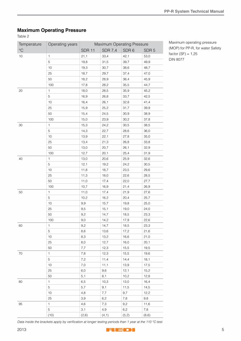
PP-R System Technical Manual
Temperature Operating years Maximum Operating Pressure°C SDR 11 SDR 7,4 SDR 6 SDR 510 1 21,1 33,4 42,1 53,0
5 19,8 31,5 39,7 49,9
10 19,3 30,7 38,6 48,7
25 18,7 29,7 37,4 47,0
50 18,2 28,9 36,4 45,9
100 17,8 28,2 35,5 44,7
20 1 18,0 28,5 35,9 45,2
5 16,9 26,8 33,7 42,5
10 16,4 26,1 32,8 41,4
25 15,9 25,2 31,7 39,9
50 15,4 24,5 30,9 38,9
100 15,0 23,9 30,2 37,8
30 1 15,3 24,2 30,5 38,5
5 14,3 22,7 28,6 36,0
10 13,9 22,1 27,8 35,0
25 13,4 21,3 26,8 33,8
50 13,0 20,7 26,1 32,9
100 12,7 20,1 25,4 31,9
40 1 13,0 20,6 25,9 32,6
5 12,1 19,2 24,2 30,5
10 11,8 18,7 23,5 29,6
25 11,3 18,0 22,6 28,5
50 11,0 17,4 22,0 27,7
100 10,7 16,9 21,4 26,9
50 1 11,0 17,4 21,9 27,6
5 10,2 16,2 20,4 25,7
10 9,9 15,7 19,8 25,0
25 9,5 15,1 19,0 24,0
50 9,2 14,7 18,5 23,3
100 9,0 14,2 17,9 22,6
60 1 9,2 14,7 18,5 23,3
5 8,6 13,6 17,2 21,6
10 8,3 13,2 16,6 21,0
25 8,0 12,7 16,0 20,1
50 7,7 12,3 15,5 19,5
70 1 7,8 12,3 15,5 19,6
5 7,2 11,4 14,4 18,1
10 7,0 11,1 13,9 17,5
25 6,0 9,6 12,1 15,2
50 5,1 8,1 10,2 12,8
80 1 6,5 10,3 13,0 16,4
5 5,7 9,1 11,5 14,5
10 4,8 7,7 9,7 12,2
25 3,9 6,2 7,8 9,8
95 1 4,6 7,3 9,2 11,6
5 3,1 4,9 6,2 7,8
(10) (2,6) (4,1) (5,2) (6,6)
Maximum Operating PressureTable 2
Data inside the brackets apply by verification at longer testing periods than 1 year at the 110 °C-test.
Maximum operating pressure
(MOP) for PP-R, for water Safety
factor (SF) = 1,25
DIN 8077

20136
PP-R System Technical Manual
Maximum Operating Pressure
Maximum operating pressure (MOP) for hot water and central
heating systems
Table 3
Maximum Operating Pressure
Heating period Temperature °C Years SDR 9 SDR 7,4 SDR 5
Continuous
operating
temperature
70 °C
incl. 60 days
per year at...
75°C 5 14,30 11,40 15,90
10 13,70 10,90 14,50
25 11,80 9,30 13,70
45 10,40 8,10 12,80
80°C 5 12,90 10,07 15,80
10 12,20 9,70 15,40
25 10,70 8,60 13,20
40 9,80 7,80 11,60
85°C 5 12,51 9,94 15,78
10 11,90 9,50 15,30
25 9,70 7,80 13,20
35 8,90 7,10 11,20
90°C 5 11,80 9,37 14,90
10 10,30 8,40 12,90
25 8,40 6,60 10,48
30 7,63 6,30 8,45
Continuous
operating
temperature
70 °C
incl. 90 days
per year at...
75°C 5 13,95 11,50 14,73
10 13,40 10,80 13,80
25 11,50 9,20 12,40
45 8,90 7,00 11,20
80°C 5 12,75 10,14 16,10
10 12,33 9,81 15,50
25 10,06 8,02 12,71
37,5 9,15 7,27 11,52
85°C 5 12,00 9,54 15,15
10 11,29 9,00 14,20
25 9,62 7,63 12,16
32,5 9,07 7,20 11,40
90°C 5 10,79 8,60 11,30
10 9,30 7,41 10,45
25 7,35 5,73 9,22 * SDR = Standard Dimension Ratio (=Diameter/Wall thickness)
72013
PP-R System Technical Manual
Maximum Operating pressures in accordance with DIN 8077 for drinking water or heating systems
Temperature and pressure play an important role in respect
of the operational safety of Wefatherm by REDI pipe systems.
Table 2 on P. 5 gives the maximum operational pressure for
the different pipe series which are defined via the SDR value
whereby a safety factor of 1.25 has been taken into account
in all cases. This table permits the pipe series appropriate for
the particular area of application in question to be selected.
Drinking water is one of our most important elements and
is accordingly subject to very strict regulations not least in
respect of the materials with which drinking water may come
into contact. Since Wefatherm by REDI pipe components
are joined by heated-sleeve welding, no substances or
materials that are detrimental to health or that are in any way
questionable come into use. Regular checks are carried out as
a matter of course by the DVGW (German Association of the
Gas and Water Profession), the SKZ (South-German Plastics
Centre) and the Technologiezentrum Wasser of the University
of Karlsruhe.
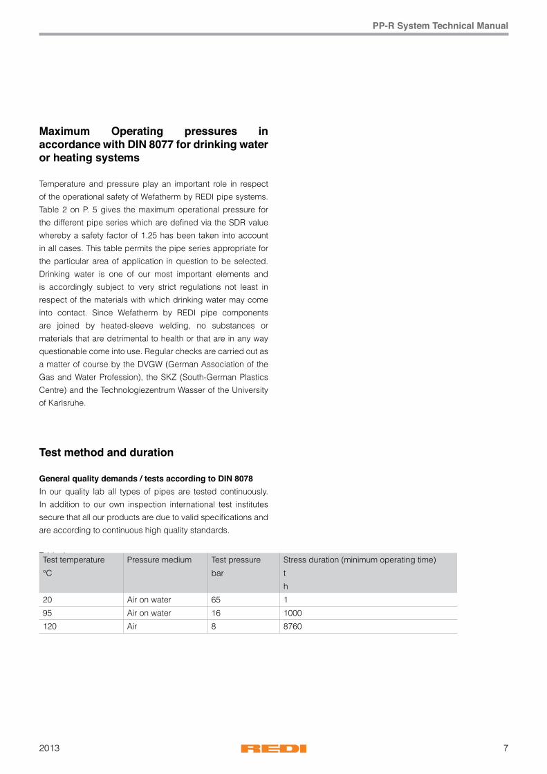
Test method and duration
General quality demands / tests according to DIN 8078In our quality lab all types of pipes are tested continuously.
In addition to our own inspection international test institutes
secure that all our products are due to valid specifications and
are according to continuous high quality standards.
Table 4Test temperature Pressure medium Test pressure Stress duration (minimum operating time)
°C bar t
h
20 Air on water 65 1
95 Air on water 16 1000
120 Air 8 8760
20138
PP-R System Technical Manual
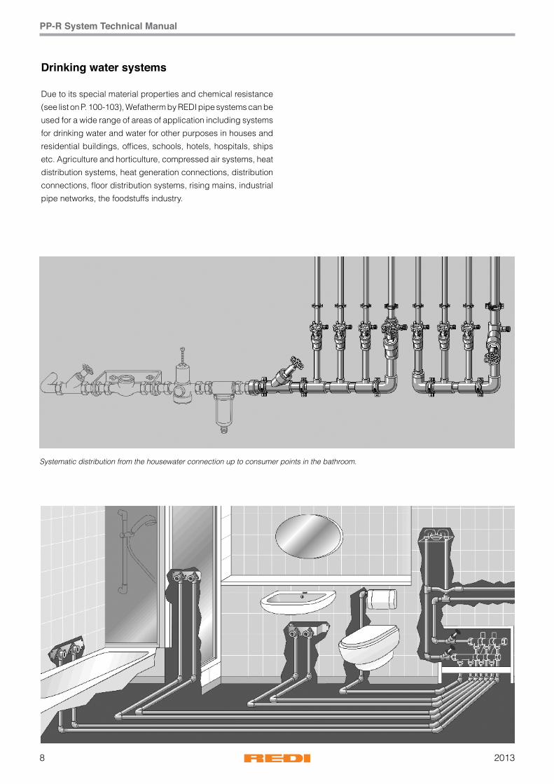
Drinking water systems
Due to its special material properties and chemical resistance
(see list on P. 100-103), Wefatherm by REDI pipe systems can be
used for a wide range of areas of application including systems
for drinking water and water for other purposes in houses and
residential buildings, offices, schools, hotels, hospitals, ships
etc. Agriculture and horticulture, compressed air systems, heat
distribution systems, heat generation connections, distribution
connections, floor distribution systems, rising mains, industrial
pipe networks, the foodstuffs industry.
Systematic distribution from the housewater connection up to consumer points in the bathroom.
92013
PP-R System Technical Manual
Drinking water systems
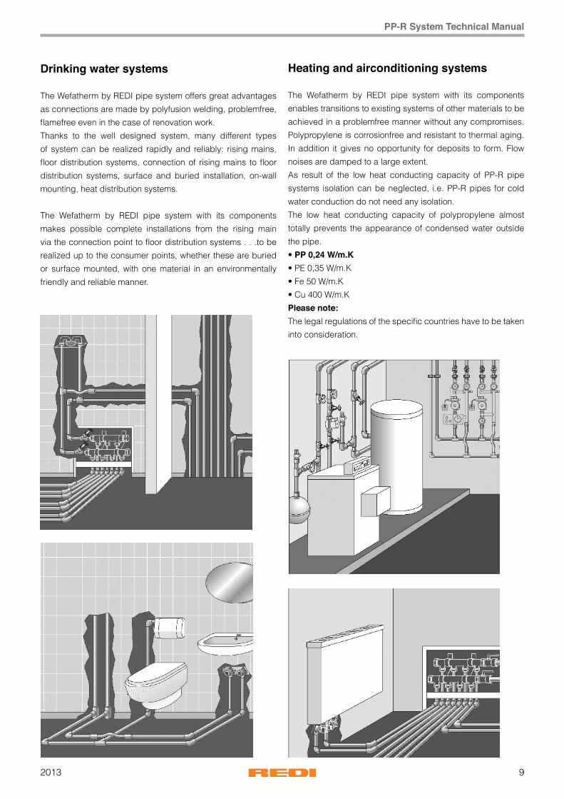
The Wefatherm by REDI pipe system offers great advantages
as connections are made by polyfusion welding, problemfree,
flamefree even in the case of renovation work.
Thanks to the well designed system, many different types
of system can be realized rapidly and reliably: rising mains,
floor distribution systems, connection of rising mains to floor
distribution systems, surface and buried installation, on-wall
mounting, heat distribution systems.
The Wefatherm by REDI pipe system with its components
makes possible complete installations from the rising main
via the connection point to floor distribution systems . . .to be
realized up to the consumer points, whether these are buried
or surface mounted, with one material in an environmentally
friendly and reliable manner.
Heating and airconditioning systems
The Wefatherm by REDI pipe system with its components
enables transitions to existing systems of other materials to be
achieved in a problemfree manner without any compromises.
Polypropylene is corrosionfree and resistant to thermal aging.
In addition it gives no opportunity for deposits to form. Flow
noises are damped to a large extent.
As result of the low heat conducting capacity of PP-R pipe
systems isolation can be neglected, i.e. PP-R pipes for cold
water conduction do not need any isolation.
The low heat conducting capacity of polypropylene almost
totally prevents the appearance of condensed water outside
the pipe.
• PP 0,24 W/m.K• PE 0,35 W/m.K
• Fe 50 W/m.K
• Cu 400 W/m.K
Please note:The legal regulations of the specific countries have to be taken
into consideration.
201310
PP-R System Technical Manual
The Wefatherm by REDI pipe system and its components
The Wefatherm by REDI pipe and the Wefatherm by REDI
Stabi pipe are two components well adjusted to their practical
application. With the help of the molded parts they can be
connected easily, even in the transition to fittings or pipe
systems of other materials.
The advantages in application of our new developed
Wefatherm by REDI Fiber pipe are low longitudinal expansion
exposition (significantly less), higher circulation with maximum
flow capacity, higher pipe stiffness as well as simple treatment
without additional peeling process.
A pipe of the new generation for every application.
In drinking water installations from the house connection point
or from the house connection distribution station up to the
last consumer point, in heating installations from the boiler
or water-heating unit up to the individual radiators or heat
exchangers: in both areas each pipe system has precisely the
right components.
In all areas of application the material polypropylene and the
Wefatherm by REDI pipe system captivate with their corrosion
resistance and high resistance to the forming of deposits,
so that long service lives can be expected. Flow noises are
damped so that systems are more user friendly than those
based on metallic materials.
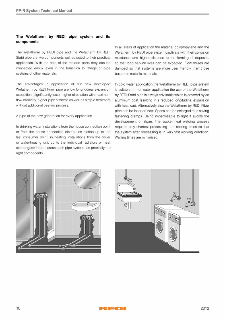
In cold water application the Wefatherm by REDI pipe system
is suitable. In hot water application the use of the Wefatherm
by REDI Stabi pipe is always advisable which is covered by an
aluminium coat resulting in a reduced longitudinal expansion
with heat load. Alternatively also the Wefatherm by REDI Fiber
pipe can be inserted now. Spans can be enlarged thus saving
fastening cramps. Being impermeable to light it avoids the
developement of algae. The socket heat welding process
requires only shortest processing and cooling times so that
the system after processing is in very fast working condition.
Waiting times are minimized.
112013
PP-R System Technical Manual
Free or surface mountingThe system consists of 100% plastic and aluminiumplastic
compound pipes, which are complemented and connected
with fittings such as collar bush flange connections, shut-
off valves, transition units from metal to PP-R and from PP-R
to metal, fitting connections and accessories. The chapter
“Product overview” shows in a clear manner the products you
need. The guarantee for our products is just as much a matter
of course for us as our product liability. Quality checks are
carried out regularly by external bodies such as the DVGW
while in addition we carry out our own regular internal checks.
Comprehensive planning and tender-preparation documents
are available to facilitate your work.
QualityFurther information on the themes of quality, certificates and
tests is provided on page 17/19.
Protection against fire and noiseUsers often find flow noise disturbing. Such noise is however
considerably reduced when the material is polypropylene.
Metallic materials often transmit much more noise. Fire
protection is regulated in accordance with national regulations.
Building authorities and fire protection officers will provide
information on this. Wefatherm by REDI pipes and fittings fulfill
the requirements of fire class B 2, i.e. they are classified as
normally inflammable. Where a pipe system passes through
structural parts of a building, steps must be taken that the
required fire resistance capabilities are restored during the
following installation.
Protection against fire and noiseThe extent and type of the protective measures required
depends on the type of installation. In particular fire walls and
ceilings must be restored to their original fire resistance class
following installation of pipes through them.
Environmental protection and recyclingPolypropylene is an environmentally friendly material.
It can be recycled up to 100%. When disposed of in
landfills, polypropylene behaves in a neutral manner visa-vis
groundwater. No poisonous residues arise when it is burnt
in refuse incineration plants. Selection of polypropylene
demonstrates consciousness of health and environmental
problems.
Chemical resistancePolypropylene is characterized by its high resistance to an
immense range of chemical substances which might pass
through a pipe system in gaseous or liquid form and at
different temperatures and pressures. Pipe connectors are
usually of brass that is nickel-plated and chromed. When it is
intended that chemical materials should pass through a pipe
system, please complete and send to us the questionnaire so
that can be downloaded from our website so that we can work
out suitable solutions with you. In this connection please see
too the chemical resistance list on pages 57 - 58.

201312
PP-R System Technical Manual
Wefatherm by REDI system quality
StandardsVarious standards such as DIN, DVS and SKZ guidelines,
ISO or DVGW worksheets form the framework for the production
monitoring of the Wefatherm by REDI system. Regular
monitoring, checks and controls not only of the fabricated
materials and production processes but also of the storage
and delivery processes are a matter of course for us and assist
us to maintain and guarantee our high standard of quality.
In addition the results of our tests are confirmed regularly by
external checks.
External checksThe Wefatherm by REDI pipe system is subjected to a multitude
of external and internal checks. National and international
authorities and institutions, the neutrality of which is out
of question, check our products regularly and certify their
constant high level of quality.
This guarantees the user a high level of safety and reliability.
Internal monitoringThe Wefatherm by REDI system quality assurance starts at our
works gate with the receipt of raw materials.
Only raw material of approved quality is processed.
Processing itself is checked regularly. The modern and
computer-controlled production machines and systems are
checked and set by qualified and experienced personnel
to ensure that they always function optimally. This gives a
continuous process monitoring system, the results of which
are documented.
Internal monitoringThe following monitoring sequence has been laid down:
checking of incoming goods, process and manufacturing
checks, intermediate checks, final checks, monitoring of
test devices. Permanent records document this sequence in
accordance with DIN ISO 9001.
Production monitoringThe settings of machines and the dimensional
correctness of test pieces are checked carefully before
production is commenced and adjustments are made
if necessary. The dimensional correctness of the items
produced, the setting data of the extrusion and injection
moulding machines and the surfaces of the products
produced are checked continuously and compared with the
production specifications. These measures ensure optimum
series production. Similar checks are also carried out regularly
in the course of production runs.
Final checksThe final products are subjected to further tests.
The results of these are laid down and documented in test
memoranda. Only products which have been checked and
released are transferred to the warehouse. When the checks
laid down in the test memoranda have been carried out and
documented, the final products are released for stockholding
and dispatch. Precise instructions and regular checks ensure
the proper storage of the products. Packing and dispatch are
regulated internally in a precise manner
External monitoringTest certificatesThe Wefatherm by REDI pipe system is regularly checked by
neutral, independent institutes. The monitoring is carried out
by the South-German Plastics Centre (SKZ), Würzburg and
TZW Karlsruhe. These are authorized as testing institutes by -
amongst other institutions - the DVGW (German Association of
the Gas and Water Profession). Analogous checks are carried
out abroad. The results of these checks are documented in
test certificates.

132013
PP-R System Technical Manual
German Quality approved
International approvals of Wefatherm by REDI

201314
PP-R System Technical Manual
NOTE
152013
PP-R System Technical Manual
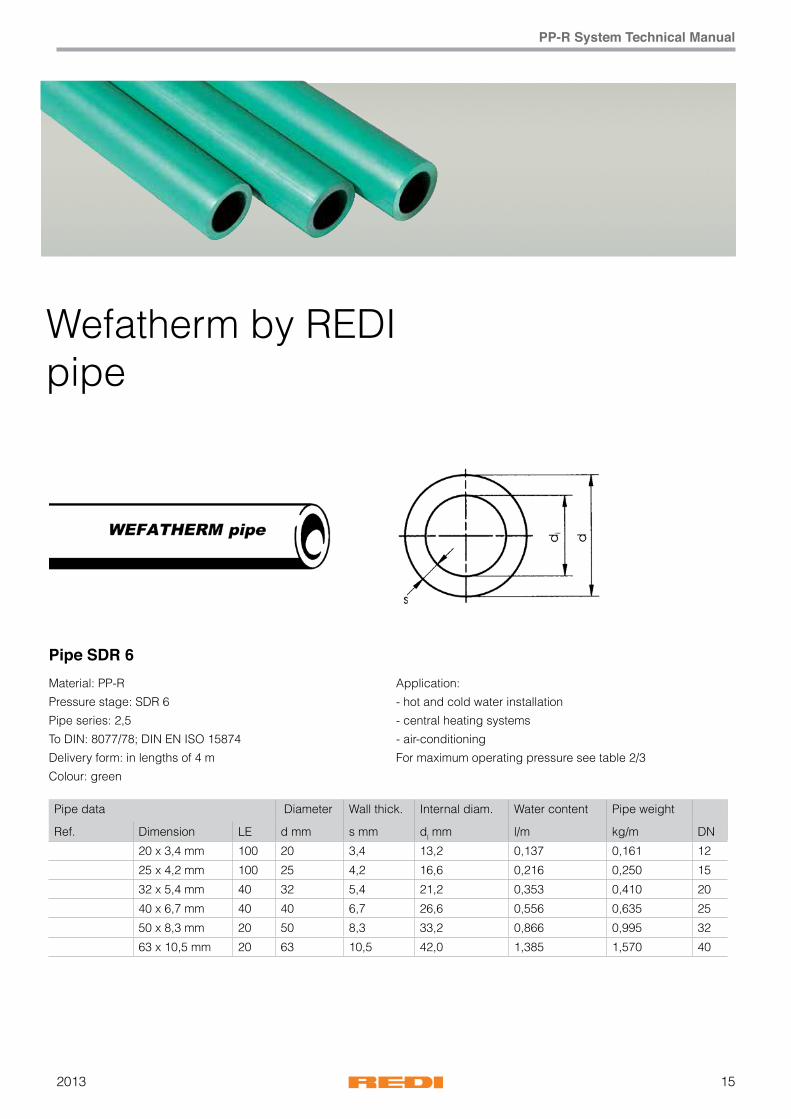
Pipe data Diameter Wall thick. Internal diam. Water content Pipe weight
Ref. Dimension LE d mm s mm dl mm l/m kg/m DN
20 x 3,4 mm 100 20 3,4 13,2 0,137 0,161 12
25 x 4,2 mm 100 25 4,2 16,6 0,216 0,250 15
32 x 5,4 mm 40 32 5,4 21,2 0,353 0,410 20
40 x 6,7 mm 40 40 6,7 26,6 0,556 0,635 25
50 x 8,3 mm 20 50 8,3 33,2 0,866 0,995 32
63 x 10,5 mm 20 63 10,5 42,0 1,385 1,570 40
Pipe SDR 6Material: PP-R
Pressure stage: SDR 6
Pipe series: 2,5
To DIN: 8077/78; DIN EN ISO 15874
Delivery form: in lengths of 4 m
Colour: green
Application:
- hot and cold water installation
- central heating systems
- air-conditioning
For maximum operating pressure see table 2/3
Wefatherm by REDI pipe

201316
PP-R System Technical Manual
Fittings
Ø ØD Ref. Pack Note(inch) (mm)
1/2” 20 QSC20RH 1/80
3/4” 25 QSC25RH 40/11/40
Ø ØD Ref. Pack Note(inch) (mm)
1/2” 20 Q7520RH 50 1
3/4” 25 Q7525RH 50 1
1” 32 Q7532RH 50 1
Ø ØD Ref. Pack Note(inch) (mm)
1/2” x 1/2” 20x1/2” QGF20RH 10 7
Ø Ref. Pack Note(inch)
20 QKIT1RH 1/40
25 QKIT2RH 1/30
Bridge
R09
Bridge with sockets
Bridge 3 pieces
Transition elbow Female-Male

172013
PP-R System Technical Manual
Ø ØD Ref. Pack Note(inch) (mm)
1/2” 20 Q2420RH 300 10
3/4” 25 Q2425RH 200 10
1” 32 Q2432RH 120 10
1”1/4 40 Q2440RH 60 5
1”1/2 50 Q2450RH 30 5
2” 63 Q2463RH 15 1
Ø ØD Ref. Pack Note(inch) (mm)
1/2” x 1/2” 20 x 1/2” QG220RH 100 10
3/4” x 1/2” 25 x 1/2” QG225RH 100 10
1/2” x 3/4” 20 x 3/4” QG320RH 100 10
3/4” x 3/4” 25 x 3/4” QG325RH 100 10
1” x 3/4” 32 x 3/4” QG332RH 80 10
1” x 1” 32 x 1” QG432RH 50 5
Ø ØD Ref. Pack Note(inch) (mm)
1/2” x 1/2” 20 x 1/2” QC220RH 100 10
3/4” x 1/2” 25 x 1/2” QC225RH 100 10
3/4” x 3/4” 25 x 3/4” QC325RH 100 10
1” x 1” 32 x 1” QC432RH 50 5
Ø ØD Ref. Pack Note(inch) (mm)
1/2” 20 Q1420RH 250 10
3/4” 25 Q1425RH 150 10
1” 32 Q1432RH 100 10
Elbow 90°
R30
R31
R35
R32
Transition-elbow/female
Transition-elbow/male
Elbow 90° female/male
201318
PP-R System Technical Manual
Ø ØD Ref. Pack Note(inch) (mm)
1/2” x 1/2” 20 x 1/2” QS220RH 100 10
3/4” x 1/2” 25 x 1/2” QS225RH 100 10
Ø ØD Ref. Pack Note(inch) (mm)
1/2” 20 Q2320RH 300 10
3/4” 25 Q2325RH 200 10
1” 32 Q2332RH 100 10
1”1/4 40 Q2340RH 60 5
1”1/2 50 Q2350RH 40 5
2” 63 Q2363RH 20 1
Ø ØD Ref. Pack Note(inch) (mm)
1/2” 20 Q1220RH 250 10
3/4” 25 Q1225RH 200 10
1” 32 Q1232RH 100 10
Ø ØD Ref. Pack Note(inch) (mm)
1/2” 20 Q4520RH 200 10
3/4” 25 Q4525RH 120 10
1” 32 Q4532RH 80 10
1”1/4 40 Q4540RH 40 5
1”1/2 50 Q4550RH 20 5
2” 63 Q4563RH 15 1
Ø ØD Ref. Pack Note(inch) (mm)
1/2” 20 Q7420RH 150 10
3/4” 25 Q7425RH 80 10
1” 32 Q7432RH 50 5
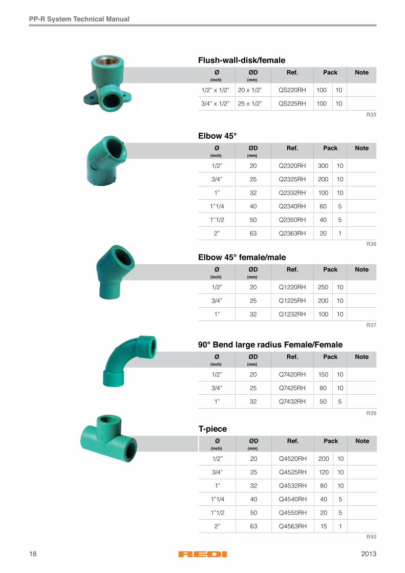
Flush-wall-disk/female
Elbow 45°
Elbow 45° female/male
T-piece
90° Bend large radius Female/Female
R33
R36
R37
R39
R40

192013
PP-R System Technical Manual
Ø ØD Ref. Pack Note(inch) (mm)
1/2” x 1/2” 20 x 1/2” QT220RH 100 10
3/4” x 1/2” 25 x 1/2” QT225RH 80 10
1/2” x 3/4” 20 x 3/4” QT320RH 80 10
3/4” x 3/4” 25 x 3/4” QT325RH 60 10
1” x 1” 32 x 1” QT432RH 50 5
Ø ØD Ref. Pack(inch) (mm)
3/4” x 1/2” x 1/2” 25 x 20 x 20 Q3525RH 120 10
3/4” x 1/2” x 3/4” 25 x 20 x 25 Q3125RH 150 10
3/4” x 3/4” x 1/2” 25 x 25 x 20 Q3625RH 120 10
1” x 1/2” x 3/4” 32 x 20 x 25 Q3732RH 80 10
1” x 1/2” x 1” 32 x 20 x 32 Q3232RH 80 10
1” x 3/4” x 1” 32 x 25 x 32 Q3132RH 80 10
1” x 1” x 3/4” 32 x 32 x 25 Q3632RH 80 10
1”1/4 x 1/2” x 1”1/4 40 x 20 x 40 Q3340RH 40 5
1”1/4 x 3/4” x 1”1/4 40 x 25 x 40 Q3225RH 40 5
1”1/4 x 1” x 1”1/4 40 x 32 x 40 Q3140RH 40 5
1”1/2 x 3/4” x 1”1/2 50 x 25 x 50 Q3350RH 20 5
1”1/2 x 1” x 1”1/2 50 x 32 x 50 Q3250RH 20 5
1”1/2 x 1”1/4 x 1”1/2 50 x 40 x 50 Q3150RH 20 5
2” x 3/4” x 2” 63 x 25 x 63 Q3463RH 15 1
2” x 1” x 2” 63 x 32 x 63 Q3363RH 15 1
2” x 1”1/4 x 2” 63 x 40 x 63 Q3263RH 15 1
2” x 1” 1/2 x 2” 63 x 50 x 63 Q3163RH 15 1
Transition T-piece/female
T-piece reduced
R49
R45

201320
PP-R System Technical Manual
Ø ØD Ref. Pack Note(inch) (mm)
1/2” 20 Q6120RH 350 10
3/4” 25 Q6125RH 300 10
1” 32 Q6132RH 150 10
1”1/4 40 Q6140RH 100 5
1”1/2 50 Q6150RH 60 5
2” 63 Q6163RH 30 1
Socket
Ø ØD Ref. Pack Note(inch) (mm)
3/4” x 1/2” 25 x 20 Q9125RH 300 10
1” x 1/2” 32 x 20 Q9232RH 200 5
1” x 3/4” 32 x 25 Q9132RH 200 10
1”1/4 x 1/2” 40 x 20 Q9220RH 100 5
1”1/4 x 3/4” 40 x 25 Q9240RH 100 10
1”1/4 x 1” 40 x 32 Q9140RH 100 5
1”1/2 x 1/2” 50 x 20 Q9251RH 100 5
1”1/2 x 3/4” 50 x 25 Q9255RH 100 5
1”1/2 x 1” 50 x 32 Q9250RH 100 5
1”1/2 x 1”1/4 50 x 40 Q9150RH 20 5
2” x 3/4” 63 x 25 Q9261RH 50 1
2” x 1” 63 x 32 Q9363RH 50 1
2” x 1”1/4 63 x 40 Q9263RH 50 5
2” x 1”1/2 63 x 50 Q9163RH 40 1
Reducer
Ø Ref. Pack Note(inch)
7/11” QA400RH 10
Repairing pin
R50
R51

212013
PP-R System Technical Manual
Ø ØD Ref. Pack Note(inch) (mm)
1/2” 20 QME20RH 35 1
3/4” 25 QME25RH 25 1
1” 32 QME32RH 20 1
1”1/4 40 QME40RH 20 1
1”1/2 50 QME50RH 15 1
2” 63 QME63RH 10 1
Ø ØD Ref. Pack Note(inch) (mm)
1/2” x 1/2” 20 x 1/2” QF220RH 200 10 A
3/4” x 1/2” 25 x 1/2” QF225RH 200 10 A
1/2” x 3/4” 20 x 3/4” QF320RH 150 10 A
3/4” x 3/4” 25 x 3/4” QF325RH 150 10 A
1” x 1” 32 x 1” QF432RH 50 5 B
1”1/4 x 1”1/4 40 x 1”1/4 QF540RH 30 5 B
1”1/2 x 1”1/2 50 x 1”1/2 QF650RH 20 1 B
2” x 2” 63 x 2” QF863RH 20 1 B
Ø ØD Ref. Pack Note(inch) (mm)
1/2” x 1/2” 20 x 1/2” QM220RH 150 10 A
3/4” x 1/2” 25 x 1/2” QM225RH 150 10 A
1/2” x 3/4” 20 x 3/4” QM320RH 100 10 A
3/4” x 3/4” 25 x 3/4” QM325RH 100 10 A
1” x 1” 32 x 1” QM432RH 50 5 B
1”1/4 x 1”1/4 40 x 1”1/4 QM540RH 50 5 B
1”1/2 x 1”1/2 50 x 1”1/2 QM650RH 30 1 B
2” x 2” 63 x 2” QM863RH 20 1 B
Electrofusion coupler, 8 V - 48 V Technology
Transition-piece female
Transition-piece male
Tipo A : Ø 20 - 25
Tipo A : Ø 20 - 25
Tipo B: dal Ø 32 al Ø 75
Tipo B: dal Ø 32 al Ø 75
R60
R55
R56

201322
PP-R System Technical Manual
Ø Ref. Pack Note(inch)
1/2” QTC20RH 400 20
3/4” QTC25RH 400 50
Ø Ref. Pack Note(inch)
1/2” QTC22RH 400 20
Ø Ref. Pack Note(inch)
1/2” QA170RH 400 20
Plugs for pressure test
Plugs for pressure test
Fixing template
Ø ØD Ref. Pack Note(inch) (mm)
1/2” 20 Q6620RH 400 10
3/4” 25 Q6625RH 300 10
1” 32 Q6632RH 200 10
1”1/4 40 Q6640RH 100 5
1”1/2 50 Q6650RH 50 5
2” 63 Q6663RH 40 1
End-cap
R80
R80
R81
R59
232013
PP-R System Technical Manual
Ø ØD Ref. Pack Note(inch) (mm)
1/2” 20 QA320RH 10 -
3/4” 25 QA325RH 10 -
1” 32 QA332RH 10 -
1”1/4 40 QA340RH 10 -
1”1/2 50 QA350RH 10 -
2” 63 QA363RH 10 -
Ø ØD Ref. Pack Note(inch) (mm)
1/2” x 3/4” 20 x 3/4” Q7120RH 50 1
3/4” x 3/4” 25 x 3/4” Q7125RH 50 1
Ø ØD Ref. Pack Note(inch) (mm)
1/2” 20 QRS20RH 50 1
3/4” 25 QRS25RH 25 1
Ø ØD Ref. Pack Note(inch) (mm)
3/4” 15 QRD25RH 40 1
Ø ØD Ref. Pack Note(inch) (mm)
1/2” 20 QRA20RH 20 1
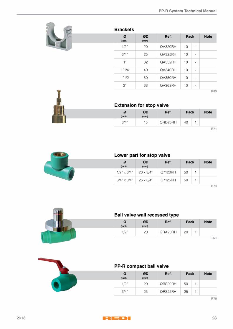
Brackets
Lower part for stop valve
PP-R compact ball valve
Extension for stop valve
Ball valve wall recessed type
R85
R71
R74
R70
R70
201324
PP-R System Technical Manual
Ø ØD Ref. Pack Note(inch) (mm)
1/2” 20 QR220RH 30 1
3/4” 25 QR225RH 30 1
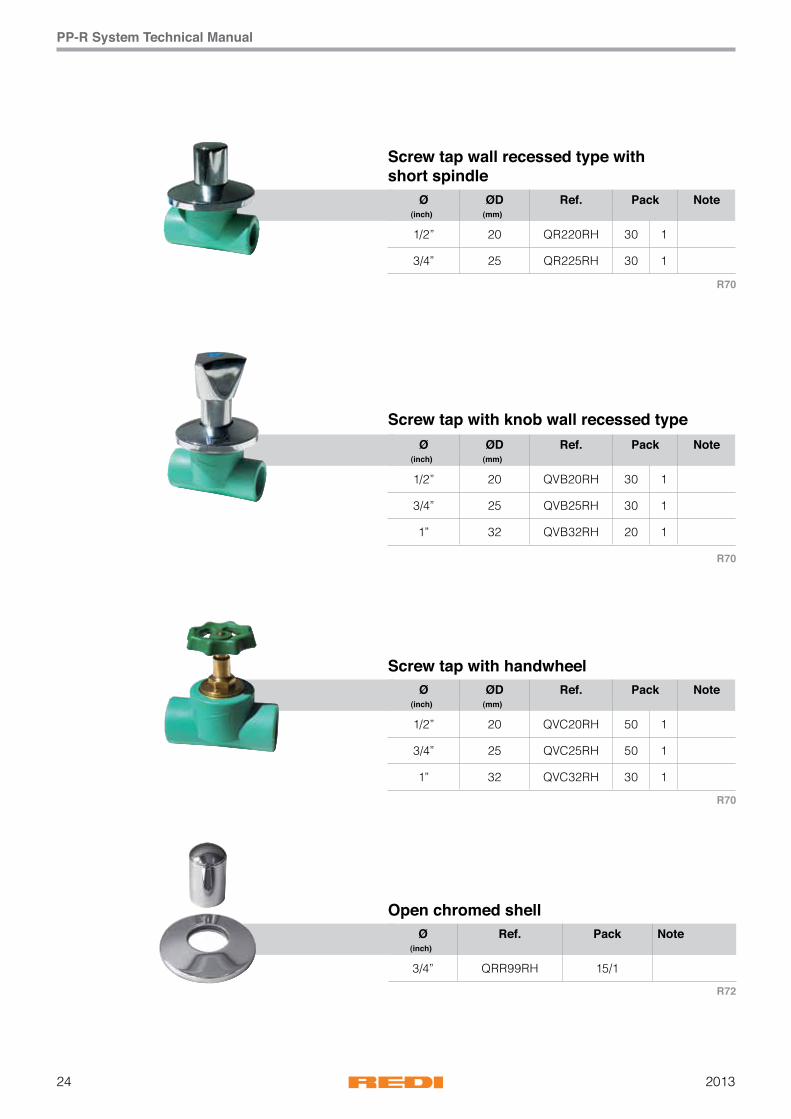
Screw tap wall recessed type with short spindle
Ø ØD Ref. Pack Note(inch) (mm)
1/2” 20 QVB20RH 30 1
3/4” 25 QVB25RH 30 1
1” 32 QVB32RH 20 1
Ø ØD Ref. Pack Note(inch) (mm)
1/2” 20 QVC20RH 50 1
3/4” 25 QVC25RH 50 1
1” 32 QVC32RH 30 1
Screw tap with knob wall recessed type
Screw tap with handwheel
Ø Ref. Pack Note(inch)
3/4” QRR99RH 15/1
Open chromed shell
R70
R70
R70
R72
252013
PP-R System Technical Manual
Ref. Pack Note
QA100RH 1
Ø Max Ref. Pack Note(mm)
63 QA110RH 1
Ø Ref. Pack Note(inch)
16 QA216RH 1 Type A
20 QA220RH 1 Type A
25 QA225RH 1 Type A
32 QA232RH 1 Type A
40 QA240RH 1 Type A
50 QA250RH 1 Type A
63 QA263RH 1 Type A
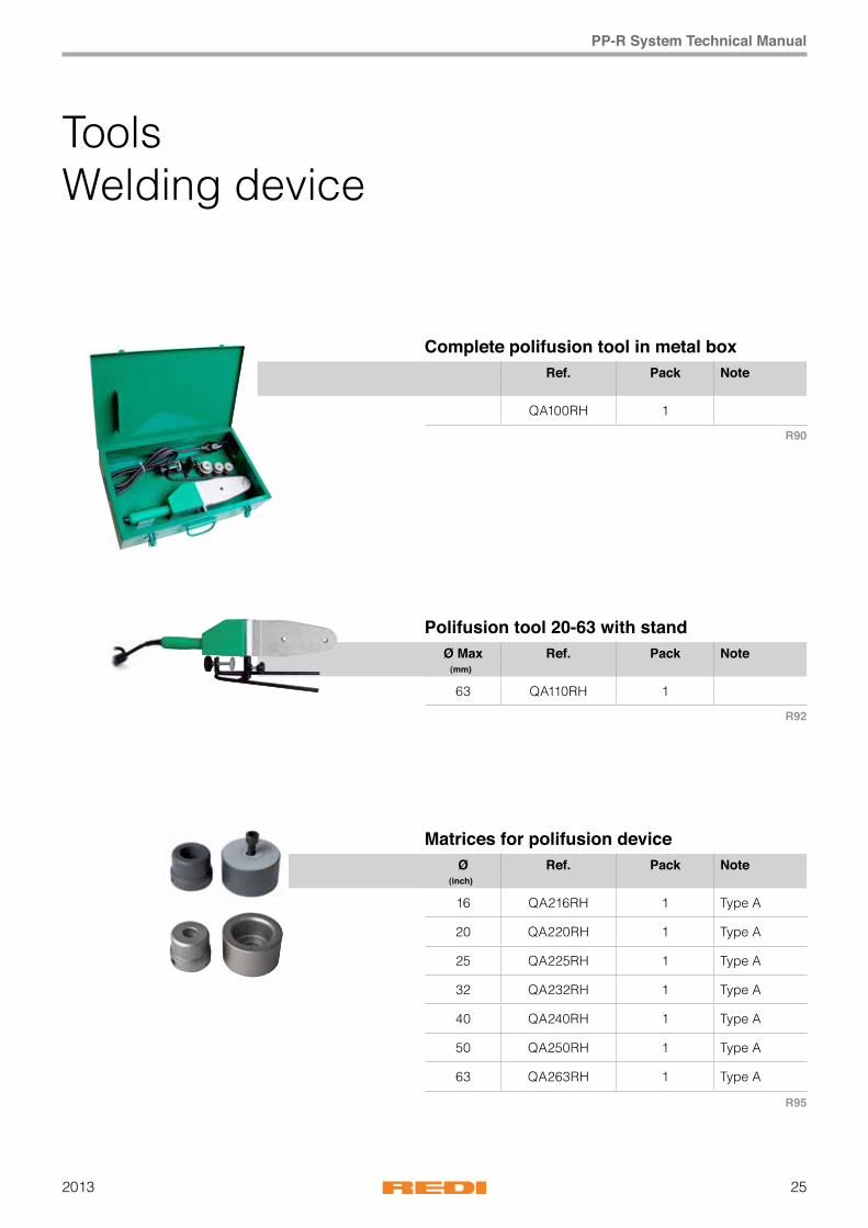
Complete polifusion tool in metal box
Polifusion tool 20-63 with stand
Matrices for polifusion device
ToolsWelding device
R90
R92
R95
201326
PP-R System Technical Manual
Ref. Pack Note
QA140RH 1
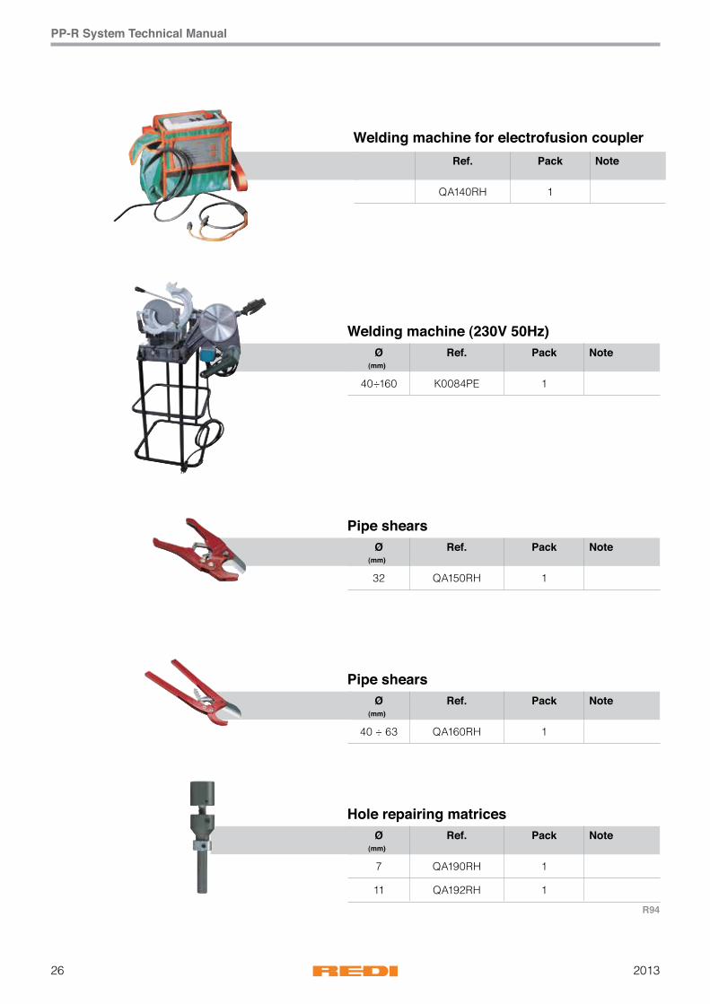
Welding machine for electrofusion coupler
Ø Ref. Pack Note(mm)
40÷160 K0084PE 1
Ø Ref. Pack Note(mm)
32 QA150RH 1
Ø Ref. Pack Note(mm)
40 ÷ 63 QA160RH 1
Ø Ref. Pack Note(mm)
7 QA190RH 1
11 QA192RH 1
Welding machine (230V 50Hz)
Pipe shears
Pipe shears
Hole repairing matrices
R94

272013
PP-R System Technical Manual
NOTE

201328
PP-R System Technical Manual
Welding andprocessing techniques
Welding device and tool
1. Only Wefatherm by REDI welding devices and tools may be
used for welding Wefatherm by REDI pipes and Wefatherm
by REDI Stabi pipes.
2. Tighten up the threaded inserts for holding the tools in cold
condition firmly with the Allen wrench and clean with a fibre-
free cloth or paper if necessary.
Screw on the tools hand tight. They may not extend beyond
the edge of the tongue!
3. Switch on the device. The thermostat lamp and control lamp
must now light up. Set the thermostat to 260°C. The heating-
up process has been completed when the thermostat lamp
goes out.
4. Tighten up the tools once again with the Allen key.
Never tighten up a tool with pliers or other tools since
this would damage the coating and could make the tool
unusable.
5. The welding tools have to be mounted according to the
diameters thus the edges do not loom over the heating
device. Tools from diameter 40 on are always to be installed
at the back hole.
6. Plug in welding device and control whether green operating
lamp is switched on. The warm-up phase takes between 5
and 20 minutes depending on the outside temperature. The
welding device is operational as soon as the orange lamp is
switched on.
7. After the device has been switched off, wait until it has
cooled down. Never cool down the device with water!
Danger of injury! In addition electronic parts such as the
thermostat could be damaged.
Remove contamination with a fibre-free cloth or paper as
well as alcohol if necessary.
8. The device may only be used when it is in a dry state. It
must be stored in dry and dust-free conditions.
9. Proper functioning of the device can only be guaranteed
when the tongue and tools are in perfect condition.
Defective or contaminated parts must always be replaced.
Defective or contaminated parts must always be replaced.
Correct
Wrong

292013
PP-R System Technical Manual
Preparations and operation
Before starting assembly, the welding tools have to
be checked for impurities. If necessary, the welding
tool needs to be cleaned by a non-fibrous cotton
cloth or rough paper cloth and possibly also with
spirit. While doing so, the Teflon coating of the tools
must not be mechanically damaged.
Safety instructions and guidelines
The general industrial hygiene and accident prevention
regulations of the particular country or state in which the
device is to be used are to be observed. In addition: General
Guidelines DVS 2208 Part 1 of the German Association for
Welding Techniques.
Welding instructions for butt-welding with Wefatherm by
REDI pipe 160 mm. General guidelines for buttwelding to
DVS 2207 Part 11 or the operating instructions from machine
manufacture. The buttwelding temperature should be 210 °C.
If welding is to be carried out outdoors when the temperature is below + 5 °C, the heating-up time in accordance with DVS 2207 Part 11 should be increased by 50 %.
General guidelines for heated-sleeve welding to DVS 2207 Part 11 Table 5
Decisive data for heated-sleeve welding
Pipe outside diameter Welding depth Heating-up time Processing time Cooling-down time
mm mm sec. sec. min.
16 13 5 4 2
20 14 5 4 2
25 15 7 4 2
32 17 8 6 4
40 18 12 6 4
50 20 18 6 4
63 26 24 8 6
75 29 30 8 8
90 32 40 8 8
110 35 50 8 8
125 41 60 10 8

201330
PP-R System Technical Manual
Processing times, welding depths
Prepare the welding device and make it ready for operation as
described in part I.
2. Cut the pipe at right angles to the axis of the pipe (Use only
Wefatherm by REDI pipe cutters or other suitable pipecutting
wrenches!)
3. Remove any cutting chips and deburr the pipe.
4. Mark the welding depth with a gauge and suitable marker
5. Align the position of the fitting with the aid of the auxiliary
marking on the fitting and the continuous line on the pipe
6. In the case of Stabi pipes, remove the aluminium cover
with the aid of the peeling tool up to the depth of welding.
(Use only original Wefatherm by REDI peeling devices with
blades in perfect condition! Replace blunt peeling blades!)
7. Insert the end of the pipe into the heating sleeve up to the
marked welding depth without turning it and at the same
time slide the fitting without turning it on to the heating
mandrel up to the stop. Observe the heatingup time given in
table 5 on P. 49 without fail!
IMPORTANT: Timing for the heating-up time should not be
commenced until the welding depth on the heating sleeve
or the stop on the heating mandrel have been reached!
8. At the end of the heating-up time, draw the pipe rapidly from
the sleeve and the fitting rapidly from the mandrel and push
them together immediately up to the point at which the mark
indicates the welding depth, being covered by the bead that
will have formed. During this process do not rotate pipe and
fitting relative to one another.
IMPORTANT: In order to prevent the internal diameter of the
pipe being reduced or in an extreme case to prevent the
pipe being closed, do not insert the pipe too far into the
fitting!
9. During the processing time keep the pipe and fitting in
constant position relative to one another. (The parts which
have been welded can still be aligned relative to one another
during this phase but may not be twisted relative to one
another!) The welded item can be fully loaded immediately
with completion of the cooling time. This welding technique
produces an inseparable union. The material of the fitting
and of the pipe will have melted together with one another.
Pipe and fitting are pushed together and become joined in an inseparable manner (do not rotate relative to one another and wait until the cooling time has expired).
The pipe is cut.
The welding depth is marked with a gaugeand suitable marker
Pipe and fitting are heated up (device 260°C ± 10°C).

312013
PP-R System Technical Manual
Wefatherm by REDI welding machine
The Wefatherm by REDI welding machine for heated-sleeve welding of PP-R pipes and fittings with diameters in the range 20 - 125 mm. The axial movements are brought about by a transport wheel and a toothed rod. V-shaped fixtures of hardened steel are provided as clamping tools for holding the workpieces. These permit the workpieces to be clamped in a manner independently of their external diameter. Two V-shaped clamps are provided on the pipe side and a single one with insert stop on the fitting side. The two tool carriages can be aligned axially. The insertion depth for welding is limited by a stop. The electronically controlled welding reflector, which can be swung into the machine, holds the heating tools which are provided with an anti-stick coating. A steel case is provided for keeping the machine and accessories in.
3) and secure with locking screw (No. 4). Insert Wefatherm by REDI pipe, Wefatherm by REDI Stabi pipe or Wefatherm by REDI Fiber pipe, the end of which has been cut at right angles, into the fitting in such a way that its face is in contact with the fitting. Clamp firmly with clamping tools (No. 7).
4. Set diameter stop (No. 1) to the diameter to be processed.5. Check welding reflector temperature and adjust if
necessary.6. Swing in welding reflector (No. 5).7. Slide in both parts to be welded at the same time up into
the heating tools (No.6) up to the stops and hold in this position for the heating-up time (for heating- up times see table 5, P. 49).
8. After the heating-up time has expired, move the carriages rapidly back and swing out mirror (No.5). Then move up pipe and press it into the fitting up to the stop and lock it in this position.
9. Remove the welded parts from the machine and align if necessary but do not rotate them relative to one another! After the cooling-down time has expired, the welded parts can be immediately subjected to the full permissible pressure.
IMPORTANT: For the heating-up, processing and cooling-down times see table 9, P. 49.
10. The next welding operation can now be commenced as previously described.
Part D: Care and maintenance1. The heating element is operated with 220 V/50 Hz.2. The guide shafts, toothed rods and trapezoidal spindles
must be kept free of dirt.3. Clean the heating sleeves/tools before commencing welding
with fibre-free paper and alcohol.4. Use only original spare parts when carrying out repairs.5. Cover the machine when not using it.
Operating instructions for the Wefatherm by REDI welding machine
Part A: Setting up the welding machine1. Remove the machine and accessories from the metal case
and place the machine on a suitable non-slip base; clamp it if necessary.
2. Slide welding reflector (No. 5) into guide.3. Fold welding reflector (No. 5) between the clamping tools
(No. 7) and adjust if necessary. Part B: Aligning the welding machine1. Select a heating mandrel (No. 6) and a heating sleeve (No.
6) in accordance with the dimensions of the pipe and fitting and fit them on the tongue (heating mandrel on the right, heating sleeve on the left).
2. Unscrew the clamping tools (No. 7) in accordance with the diameter of the pipe and fitting.
3. Clean tools, pipe and fitting with fibre-free, undyed paper and alcohol on the inside and outside.
4. Heat up the welding reflector and set the welding temperature (260°C), observing manufacturer‘s instructions. The processing temperature has been reached and the device is ready for use when the control lamp goes out.
Part C: Welding1. Press fitting into clamping tool (No. 7) up to the stop (No.
9) and clamp firmly.2. Push the button (No. 3).3. Move the carriage with handwheel (No. 2) up to stop (No.
201332
PP-R System Technical Manual
Health and safety regulationsThere is always a certain risk of injury when operatingwith plastic pipe welding machines. Observation of thefollowing accident prevention regulations reduces thisdanger to a minimum. Non-observation of them canlead to accidents!1. Dirty and untidy workplaces increase the chances for
accidents.2. Ambient surroundings: Protect electrical tools from rain
and drips. Do not use them in wet or moist rooms. Keep onlookers and visitors away from the places where welding is carried out (safety distance).
3. Storage: Store machines and devices under dry conditions and secured against unauthorized access.
4. Working clothing: Wear tightly fitting clothing and no rings or jewellery when working; loose clothing and rings or jewellery could be caught by moving parts.
5. Electrical parts: Before connecting a device to the mains, check that it is switched off. Always pull out the plug before carrying repairs. Replace damaged or brittle connection cables and pull reliefs immediately.
Protect cables from heat and sharp edges. Never pull plugs out of the socket by pulling on the cable. Never carry a device by the cable.
6. Workpieces: Ensure that pipe and fitting are always located firmly in the clamping devices.
7. Danger of injury: Beware of squashing when closing the clamps.
8. Danger of burning: The metal parts on the heating element will have temperatures up to 300 °C. Take precautions so that it is not possible to touch them. Keep inflammable materials at a safe distance away.
9. Spare parts: Replace damaged parts immediately; protect electrical parts carefully - dirt and moisture are very good electrical conductors. Use only original spare parts. Always state the machine number and version number when ordering spare parts.
Electrofusion welding 8 V- 48 V technologyThe Wefatherm by REDI welding device for the electric weldingsleeves has been developed for use on building sites. Itis protected against dust, dirt, rain and drips of water when it is in its case. Suitable for use at ambient temperatures from approx. --10 °C to 60 °C.Supply Voltage: 230 V / 50 HzWelding Voltage: 8 - 48 V technologyElectric welding sleeves are only useable without stress on the pipes!1. The ends of pipes must be cut in right angles and must
be free of dust and dirt; clean them if necessary.2. Strip the cover from Wefatherm by REDI Stabi pipes
back to the welding depth. Use only original Wefatherm by REDI peeling tools.
3. Cleaning The surfaces of the pipes to be fused and the interior
surfaces of the Wefatherm by REDI Electro fusion Fittings must be absolutely clean, dry and free from any grease. These areas are to be cleaned with a suitable cleaning agent and exclusively with absorbent, lintfree and non-dyed paper directly before the assembly and after scraping. An approved PP-cleaner has to be used.
4. Do not remove the Wefatherm by REDI electric welding sleeves from their protective packing until immediately before commencing welding. They too must be kept free of dirt, dust and grease.
5. Place on the electric welding sleeve and slide in the two pipe ends (up to the stop) and fix the pipes in this position during the welding and cooling process.
6. Connect the welding device to the electric welding sleeve and start the welding process.
7. Wait until the heating time has ended.8. Disconnect the cable from the electric welding sleeve.9. Maintain the cooling-down times without fail (See table 6a)!
Further information is enclosed with the device and should be observed.
Table 6a - Type of loading Pressure load Minimum waiting period
Tensile stress, bending or twisting of lines that are not under pressure 20 minutes
Subjection of lines to test our operational pressure up to 0,1 bar
0,1 up to 1 bar
over 1 bar
20 minutes
60 minutes
120 minutes
Repeat of a welding process 60 minutes
Table 6b Years of operation
Temperature °C 1 5 10 25 50 100
Permissible pressure [bar] (SF=1,25 – ISO 12162)
10 33,4 31,6 30,6 29,6 28,8 28,1
20 28,6 26,8 26,1 25,3 24,5 23,8
30 24,3 22,8 22,0 21,3 20,7 –
40 20,5 19,2 18,7 18,0 17,5 –
50 17,5 16,2 15,7 15,2 14,7 –
60 14,7 13,7 13,2 12,6 12,1 –
70 12,4 11,4 11,1 9,6 8,1 –
80 10,4 9,1 7,6 6,1 – –
95 7,3 4,8 4,0 – – –
332013
PP-R System Technical Manual
Installation Types of laying
All components of the Wefatherm by REDI pipe system are fundamentally suitable for use in sanitary and heating applications and are thus also suitable for the different methods of installation employed in these areas. As a result of this the planner or the craftsmen‘s firm carrying out the work can decide how to carry out an installation, i.e. in shafts, with pipes buried in plaster or on the surface of plaster or also laying direct in concrete or floor topping. In the following sections the different ways of carrying out installations in an optimum manner, of observing the insulation regulations and of solving problems resulting from thermal longitudinal expansion are dealt with. You can obtain information on how to deal with this problem from the tables and examples given in the chapter on longitudinal expansion. The section on mounting techniques indicate the ways of carrying out installation in such a way that the particular design requirements can be met. In addition we treat insulation, pressure testing and testing of systems.
Buried laying
Longitudinal expansion does not necessarily have to be taken into account even with buried laying. If a system has to be insulated in accordance with the relevant regulations, the insulation will absorb the longitudinal expansion arising without any problem. In other words the laying space only needs to be executed in accordance with the thickness of insulation. Problems resulting from longitudinal expansion generally do not arise. Pipes, which do not have to be insulated, can be laid in floor topping or concrete or buried beneath plaster when clamped appropriately without measures having to be taken to compensate for longitudinal expansion. In this way longitudinal expansion arising from heat will be uncritical since it will be absorbed by the material.
Outlets in shafts
As a rule installation for outlets in shafts can be carried out in a variety of different ways. In addition to lines for the supplying of individual floors, there can be lines to a tank at the top of a building. As a result of these tasks, there will be a number of
outlet points in a shaft. The longitudinal expansion is the same as in any other position or installation. So please take care of the expansion. Lengths of pipes between clamps should not exceed 3 m. Care should be taken that holes in walls are sufficiently large to give the pipe adequate freedom of movement and in order to provide space for insulation material if necessary
Exposed/surface laying
Fundamentally it will always be possible to lay a Wefatherm by REDI pipe network in an open and visible manner. Since with exposed or surface laying the pipe system will always be visible, high requirements will be placed here on the optical aspects in general. As a result of its high dimensional stability and reduced longitudinal expansion, Wefatherm by REDI Stabi pipework is specially suitable for systems laid in an exposed manner. Since the coefficient of longitudinal expansion of the Stabi pipes is a = 0,030 mm/mK and Fiber pipe a = 0,035 mm/mK, longitudinal expansion compensation measures are not necessary except with very long, free lengths of pipe. Wefatherm by REDI standard pipe has an expansion coefficient of a = 0,15 mm/mK and - for exposed laying - its use should be restricted to cold-water applications since here no longitudinal expansion problems will arise. Optically acceptable pipework can be achieved subject to observation of the permissible effective spans (see tables 10a-10d, P. 67).
Longitudinal expansion
Wefatherm by REDI pipe systems extend when subjected to heat in accordance with their different material characteristics. The longitudinal expansions of the Wefatherm by REDI Stabi pipe or Wefatherm by REDI Fiber pipes are considerably much less than that of the 100 % plastic pipe. The method of calculating the longitudinal expansion theoretically is given in an example. For practical use we have shown the longitudinal expansion to be expected with the three different materials in tables. From these the longitudinal expansion to be expected for a particular free length of pipe can be read off. Of decisive importance for the determination of the longitudinal expansion is the difference between the temperature at which the pipework is installed and the maximum operating temperature to be expected (see tables 7-9, P. 61 and 62). After the longitudinal expansion to be expected has been determined, a decision can be taken on which if any of the possible different measures should be taken to compensate for it.
201334
PP-R System Technical Manual
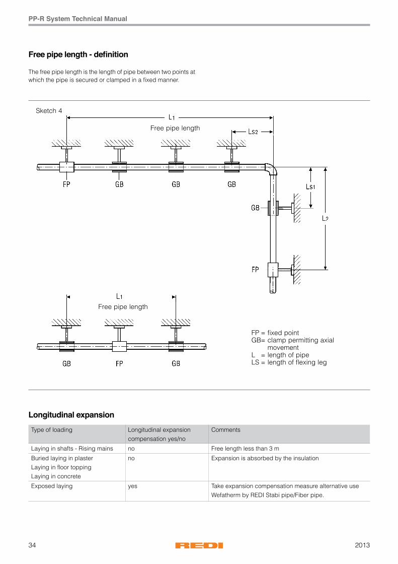
Free pipe length - definition
The free pipe length is the length of pipe between two points at which the pipe is secured or clamped in a fixed manner.
Longitudinal expansionType of loading Longitudinal expansion
compensation yes/noComments
Laying in shafts - Rising mains no Free length less than 3 m
Buried laying in plasterLaying in floor toppingLaying in concrete
no Expansion is absorbed by the insulation
Exposed laying yes Take expansion compensation measure alternative use Wefatherm by REDI Stabi pipe/Fiber pipe.

352013
PP-R System Technical Manual
Calculation example for longitudinal expansion
The longitudinal expansion is calculated as follows:Δ = a x L x Δt
The meaning is:Δ = longitudinal expansion in mma = linear expansion factor for Wefatherm by REDI standard pipe 0,150 mm/m ⋅ K for Wefatherm by REDI Stabi pipe 0,030 mm/m ⋅ K for Wefatherm by REDI Fiber pipe 0,035 mm/m ⋅ KL = Length of pipe in mΔt = temperature difference between assembly temperature and operation temperature
Calculation example for longitudinal expansion:Longitudinal expansion of Wefatherm by REDI pipe; = 0,15 mm/m · KPipe lengthin metres (m)
Temperature difference Δt (K)10 20 30 40 50 60 70 80
0,1 0,15 0,30 0,45 0,60 0,75 0,90 1,05 1,100,2 0,30 0,60 0,90 1,20 1,50 1,80 2,10 2,400,3 0,45 0,90 1,35 1,80 2,25 2,70 3,15 3,600,4 0,60 1,20 1,80 2,40 3,00 3,60 4,20 4,800,5 0,75 1,50 2,25 3,00 3,75 4,50 5,25 6,000,6 0,90 1,80 2,70 3,60 4,50 5,40 6,30 7,200,7 1,05 2,10 3,15 4,20 5,25 6,30 7,35 8,400,8 1,20 2,40 3,60 4,80 6,00 7,20 8,40 9,600,9 1,35 2,70 4,05 5,40 6,75 8,10 9,45 10,801,0 1,50 3,00 4,50 6,00 7,50 9,00 10,50 12,002,0 3,00 6,00 9,00 12,00 15,00 18,00 21,00 24,003,0 4,50 9,00 13,50 18,00 22,50 27,00 31,50 36,004,0 6,00 12,00 18,00 24,00 30,00 36,00 42,00 48,005,0 7,50 15,00 22,50 30,00 37,50 45,00 52,50 60,006,0 9,00 18,00 27,00 36,00 45,00 54,00 63,00 72,007,0 10,50 21,00 31,50 42,00 52,50 63,00 73,50 84,008,0 12,00 24,00 36,00 48,00 60,00 72,00 84,00 96,009,0 13,50 27,00 40,50 54,00 67,50 81,00 94,50 108,0010,0 15,00 30,00 45,00 60,00 75,00 90,00 105,00 120,00
Table 7a

201336
PP-R System Technical Manual
Longitudinal expansion in mm
Longitudinal expansion of Wefatherm by REDI Stabi pipe; a = 0,03 mm/m ⋅ K
Longitudinal expansion of Wefatherm by REDI Fiber pipe; a = 0,035 mm/m ⋅ K
Pipe lengthin metres (m)
Temperature difference Δt (K)
10 20 30 40 50 60 70 80
0,1 0,03 0,06 0,09 0,12 0,15 0,18 0,21 0,24
0,2 0,06 0,12 0,18 0,24 0,30 0,36 0,42 0,48
0,3 0,09 0,18 0,27 0,36 0,45 0,54 0,63 0,72
0,4 0,12 0,24 0,36 0,48 0,60 0,72 0,84 0,96
0,5 0,15 0,30 0,45 0,60 0,75 0,90 1,05 1,20
0,6 0,18 0,36 0,54 0,72 0,90 1,08 1,26 1,44
0,7 0,21 0,42 0,63 0,84 1,05 1,26 1,47 1,68
0,8 0,24 0,48 0,72 0,96 1,20 1,44 1,68 1,92
0,9 0,27 0,54 0,81 1,08 1,35 1,62 1,89 2,16
1,0 0,30 0,60 0,90 1,20 1,50 1,80 2,10 2,40
2,0 0,60 1,20 1,80 2,40 3,00 3,60 4,20 4,80
3,0 0,90 1,80 2,70 3,60 4,50 5,40 6,30 7,20
4,0 1,20 2,40 3,60 4,80 6,00 7,20 8,40 9,60
5,0 1,50 3,00 4,50 6,00 7,50 9,00 10,50 12,00
6,0 1,80 3,60 5,40 7,20 9,00 10,80 12,60 14,40
7,0 2,10 4,20 6,30 8,40 10,50 12,60 14,70 16,80
8,0 2,40 4,80 7,20 9,60 12,00 14,40 16,80 19,20
9,0 2,70 5,40 8,10 10,80 13,50 16,20 18,90 21,60
10,0 3,00 6,00 9,00 12,00 15,00 18,00 21,00 24,00
Pipe lengthin metres (m)
Temperature difference Δt (K)
10 20 30 40 50 60 70 80
0,1 0,04 0,07 0,11 0,14 0,18 0,21 0,25 0,28
0,2 0,07 0,14 0,21 0,28 0,35 0,42 0,49 0,56
0,3 0,11 0,21 0,32 0,42 0,53 0,63 0,74 0,84
0,4 0,14 0,28 0,42 0,56 0,70 0,84 0,98 1,12
0,5 0,18 0,35 0,53 0,70 0,88 1,05 1,23 1,40
0,6 0,21 0,42 0,63 0,84 1,05 1,26 1,47 1,68
0,7 0,25 0,49 0,74 0,98 1,23 1,47 1,72 1,96
0,8 0,28 0,56 0,84 1,12 1,40 1,68 1,96 2,24
0,9 0,32 0,63 0,95 1,26 1,58 1,89 2,21 2,52
1,0 0,35 0,70 1,05 1,40 1,75 2,10 2,45 2,80
2,0 0,70 1,40 2,10 2,80 3,50 4,20 4,90 5,60
3,0 1,05 2,10 3,15 4,20 5,25 6,30 7,35 8,40
4,0 1,40 2,80 4,20 5,60 7,00 8,40 9,80 11,20
5,0 1,75 3,50 5,25 7,00 8,75 10,50 12,25 14,00
6,0 2,10 4,20 6,30 8,40 10,50 12,60 14,70 16,80
7,0 2,45 4,90 7,35 9,80 12,25 14,70 17,15 19,60
8,0 2,80 5,60 8,40 11,20 14,00 16,80 19,60 22,40
9,0 3,15 6,30 9,45 12,60 15,75 18,90 22,05 25,20
10,0 3,50 7,00 10,50 14,00 17,50 21,00 24,50 28,00
Table 8
Table 9
372013
PP-R System Technical Manual
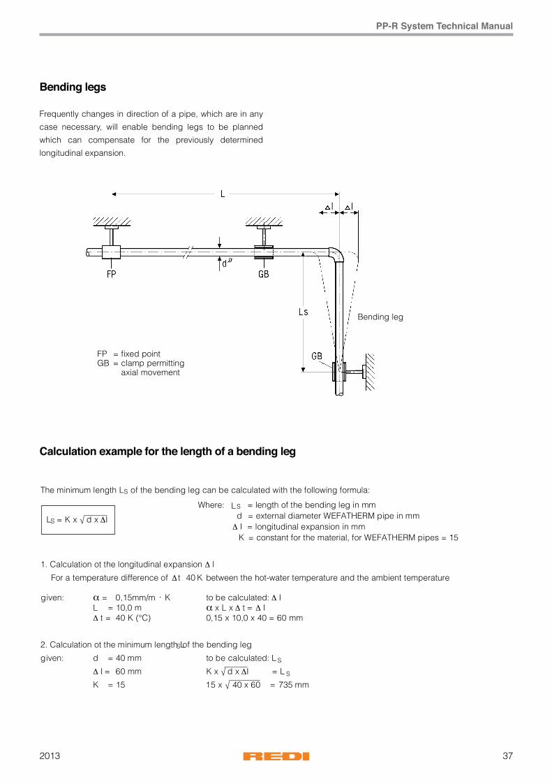
Bending legs
Frequently changes in direction of a pipe, which are in any
case necessary, will enable bending legs to be planned
which can compensate for the previously determined
longitudinal expansion.
Calculation example for the length of a bending leg
The minimum length LS of the bending leg can be calculated with the following formula:
Where: LS = length of the bending leg in mm d = external diameter WEFATHERM pipe in mm Δ I = longitudinal expansion in mm K = constant for the material, for WEFATHERM pipes = 15
1. Calculation ot the longitudinal expansion Δ l
For a temperature difference of Δ t4 0 K between the hot-water temperature and the ambient temperature
given: a = 0,15mm/m · K to be calculated: Δ I L = 10,0 m a x L x Δ t = Δ I Δ t = 40 K (°C) 0,15 x 10,0 x 40 = 60 mm
2. Calculation ot the minimum length LS of the bending leg
given: d = 40 mm to be calculated: L S
Δ I = 60 mm K x √ d x ΔI = L S
K = 15 15 x √ 40 x 60 = 735 mm
LS = K x √ d x ΔI
t4
201338
PP-R System Technical Manual
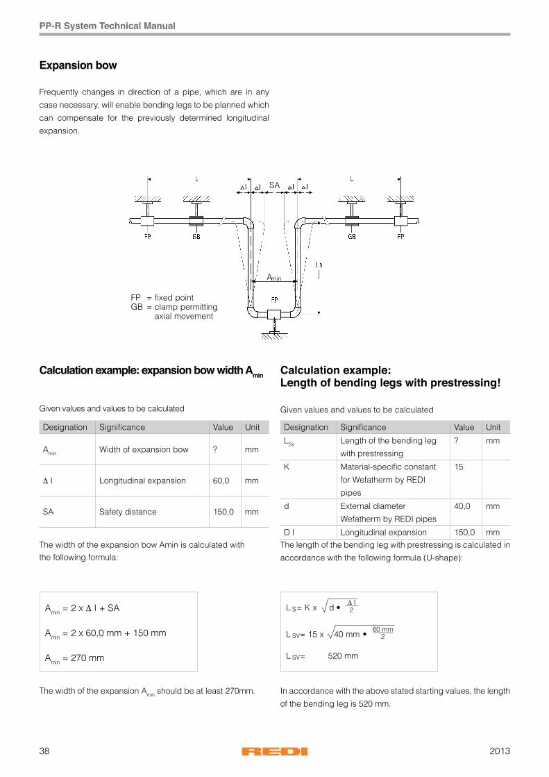
Expansion bow
Frequently changes in direction of a pipe, which are in any
case necessary, will enable bending legs to be planned which
can compensate for the previously determined longitudinal
expansion.
Calculation example:Length of bending legs with prestressing!
Given values and values to be calculated
Calculation example: expansion bow width Amin
Given values and values to be calculated
Designation Significance Value Unit
Amin Width of expansion bow ? mm
Δ I Longitudinal expansion 60,0 mm
SA Safety distance 150,0 mm
Designation Significance Value Unit
LSV Length of the bending leg
with prestressing
? mm
K Material-specific constant
for Wefatherm by REDI
pipes
15
d External diameter
Wefatherm by REDI pipes
40,0 mm
D I Longitudinal expansion 150,0 mmThe width of the expansion bow Amin is calculated withthe following formula:
Amin = 2 x Δ I + SA
Amin = 2 x 60,0 mm + 150 mm
Amin = 270 mm
The width of the expansion Amin should be at least 270mm.
The length of the bending leg with prestressing is calculated in
accordance with the following formula (U-shape):
In accordance with the above stated starting values, the length
of the bending leg is 520 mm.
392013
PP-R System Technical Manual
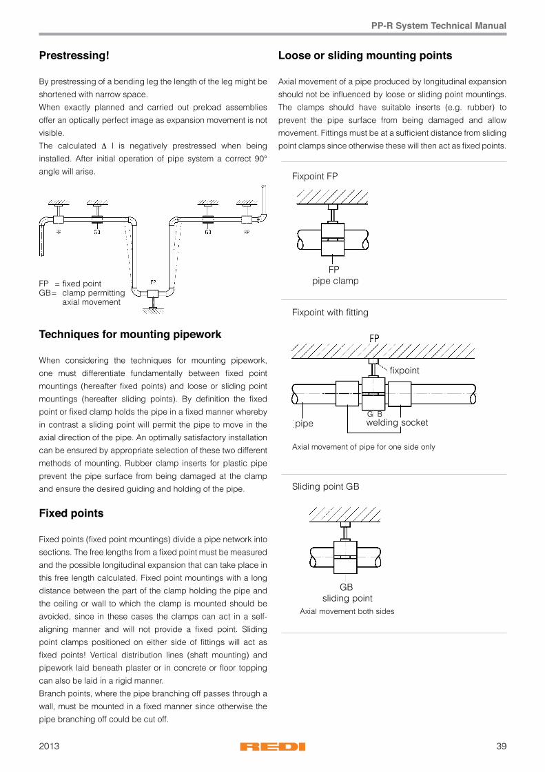
Prestressing!
By prestressing of a bending leg the length of the leg might be
shortened with narrow space.
When exactly planned and carried out preload assemblies
offer an optically perfect image as expansion movement is not
visible.
The calculated Δ l is negatively prestressed when being
installed. After initial operation of pipe system a correct 90°
angle will arise.
Techniques for mounting pipework
When considering the techniques for mounting pipework,
one must differentiate fundamentally between fixed point
mountings (hereafter fixed points) and loose or sliding point
mountings (hereafter sliding points). By definition the fixed
point or fixed clamp holds the pipe in a fixed manner whereby
in contrast a sliding point will permit the pipe to move in the
axial direction of the pipe. An optimally satisfactory installation
can be ensured by appropriate selection of these two different
methods of mounting. Rubber clamp inserts for plastic pipe
prevent the pipe surface from being damaged at the clamp
and ensure the desired guiding and holding of the pipe.
Fixed points
Fixed points (fixed point mountings) divide a pipe network into
sections. The free lengths from a fixed point must be measured
and the possible longitudinal expansion that can take place in
this free length calculated. Fixed point mountings with a long
distance between the part of the clamp holding the pipe and
the ceiling or wall to which the clamp is mounted should be
avoided, since in these cases the clamps can act in a self-
aligning manner and will not provide a fixed point. Sliding
point clamps positioned on either side of fittings will act as
fixed points! Vertical distribution lines (shaft mounting) and
pipework laid beneath plaster or in concrete or floor topping
can also be laid in a rigid manner.
Branch points, where the pipe branching off passes through a
wall, must be mounted in a fixed manner since otherwise the
pipe branching off could be cut off.
FP GB = clamp permitting = axial movement
Sliding point GB
Fixpoint FP
Axial movement both sides
FPpipe clamp
GBsliding point
Axial movement of pipe for one side only
pipe welding socketG B
Loose or sliding mounting points
Axial movement of a pipe produced by longitudinal expansion
should not be influenced by loose or sliding point mountings.
The clamps should have suitable inserts (e.g. rubber) to
prevent the pipe surface from being damaged and allow
movement. Fittings must be at a sufficient distance from sliding
point clamps since otherwise these will then act as fixed points.

201340
PP-R System Technical Manual
Wefatherm by REDI pipes
Wefatherm by REDI Stabi pipes
Wefatherm by REDI Fiber pipes
Recommended spans LA at pipe wall temperature TR
Recommended spans LA at pipe wall temperature TR
Recommended spans LA at pipe wall temperature TR
Table 10a
Table 10b
Table 10c
Pipe wall
temperature
TR [°C]
Pipe diameter d [mm]
16 20 25 32 40 50 63 75 90 110 125
Recommended spans LA [cm] (Montage distance)
0 70 85 105 125 140 165 190 205 220 250 250
20 50 60 75 90 100 120 140 150 160 180 190
30 50 60 75 90 100 120 140 150 160 180 190
40 50 60 70 80 90 110 130 140 150 170 180
50 50 60 70 80 90 110 130 140 150 170 180
60 50 55 65 75 85 100 115 125 140 160 170
70 50 50 60 70 80 95 105 105 125 140 150
Pipe wall
temperature
TR [°C]
Pipe diameter d [mm]
16 20 25 32 40 50 63 75 90 110 125
Recommended spans LA [cm] (Montage distance)
0 130 155 170 195 220 245 270 285 300 325 340
20 100 120 130 150 170 190 210 220 230 250 265
30 100 120 130 150 170 190 210 220 230 240 255
40 100 110 120 140 160 180 200 210 220 230 245
50 100 110 120 140 160 180 200 210 220 210 225
60 80 100 110 130 150 170 190 200 210 200 210
70 70 90 100 120 140 160 180 190 200 200 210
Pipe wall
temperature
TR [°C]
Pipe diameter d [mm]
16 20 25 32 40 50 63 75 90 110 125
Recommended spans LA [cm] (Montage distance)
0 120 140 160 180 205 230 245 260 290 320 340
20 90 105 120 135 155 175 185 195 215 240 265
30 90 105 120 135 155 175 185 195 210 230 255
40 85 95 110 125 145 165 175 185 200 220 245
50 85 95 110 125 145 165 175 185 190 205 225
60 80 90 105 120 135 155 165 175 180 190 210
70 70 80 95 110 130 145 155 165 170 180 210

412013
PP-R System Technical Manual
Insulation cold water lines
Energy-saving is environmental protection.
The legal regulation of the specific countries have to be taken
into consideration.
Insulation warm water lines
In spite of the high level of insulation it provides itself, pipework
of Wefatherm by REDI must be insulated to prevent noise
and heat lost. This can be derived from the Drinking Water
System Order in accordance with DIN 1988 Part 2. For more
Information pls. contact our technical support.
Condensation point
• The normal case is a cellar submerged to two thirds of the
wall height in the earth, that has no continuously opened
doors and windows.
• Such a ”normal case“ stays even in summer after strong rain
below a room temperature of 25 °C and 60 % moisture.
Guideline values for minimum thicknesses of insulation for insulating drinking water systems (cold)
Mounting situationInsulating layer thickness at l = 0,040 W (m K)
Pipework laid exposed in unheated, room (e.g. basement) 4 mm
Pipework laid exposed in heated room 9 mm
Pipework laid in channel with additional heated pipe lines 4 mm
Pipework laid in channel next to heated pipe lines 13 mm
Pipework laid in masony slit Rising main 4 mm
Pipework laid in wall recess next to heated pipe lines 13 mm
Pipework laid on cement floor 4 mm
• With 25 °C and 60 % moisture and 10 °C water temperature
the pipe begins to sweat.
• For southern regions is important that these temperatures
are sometimes exceeded, but the water temperature is often
higher than 10 °C.
• With all rooms not according to standard cellar, it has to
be determined from case to case, whether maximum room
temperature may be 15 °C higher than the water temperature.
• For SDR 11 pipes the permissible temperature difference is
at 11 °C.
Result: Cold water systems consisting of SDR 6 pipe normally do not have to be insulated against condensation water.
201342
PP-R System Technical Manual
Pressure test
After a drinking water system has been installed but before it
is commissioned, it must be tested for tightness whereby this
should be done while the system is still visible. Polypropylene
expands under the influence of heat and pressure. For this
reason it is necessary that the test medium (as a rule water) and
the pipework material are at the same temperature. Attention
should therefore be paid to the fact that the test medium has a
temperature that is as constant as possible. The pressure test
is divided into three parts, namely the initial, the main and the
final test.
Initial test
The highest possible operating pressure is increased by
a factor of 1.5. This test pressure must be restored twice at
intervals of in each case 10 minutes within a period of 30
minutes. After the pressure has been restored again a second
time, the test pressure may not fall by more than 0.6 bar within
the next 30 minutes. In addition no leakage may occur.
Main test
The main test commences immediately after the completion
of the initial test and lasts two hours. During this period the
pressure may not fall by more than 0.2 bar relative to the
pressure at the end of the initial test.
Final test
Test pressures of 10 bar and 1 bar are applied alternately
at intervals of at least 5 minutes. After each application of
pressure, the pipe network is to be depressurized. Leakage
may not occur at any point in the network being tested.
Measuring devices
The pressure measuring device used must permit accurate
readings to the nearest 0.1 bar. Where possible the pressure is
to be determined at the lowest point of the network.
Test memorandum
The test as carried out is to be documented in a memorandum
which must be signed by the client and contractor with
statement of the place and date of signing (see p. 73 for a test
memorandum form).
Flushing out of pipework systems
The sense and purpose of flushing out pipework systems:
Ensuring the quality of drinking water, avoi- dance of corrosion
damage, avoidance of damage to fittings and equipment,
cleaning of the inner surface of the pipes. Regardless of the
material of the pipes, all pipework systems carrying drinking
water are to be flushed out. Suitable process are: 1. Flushing
out with water 2. Flushing out with a mixture of air and water
Flushing out process 1, namely flushing out with water, is
sufficient in the case of drinking water systems which are
composed exclusively of Wefatherm by REDI pipes and fittings.
The appropriate flushing out process should be selected on
the basis of the experience of the installing firm and of the
client.
Transport and storage
Thanks to the excellent properties of the material from which
Wefatherm by REDI pipe systems are manufactured, the pipes
and fittings can fundamentally be stored at all temperatures
without any problems. The storage place should, however, be
selected in accordance with the following conditions:
1. The pipes should be supported along their full length.
2. Bending of the pipes is to be avoided.
3. The material becomes sensitive to impact at low temperatures
and in particular at temperatures below zero °C. For this
reason knocks and similar impacts are to be avoided under
these conditions.
4. High-polymer materials are sensitive to UV radiation. For
this reason Wefatherm by REDI material should also be
protected against the effects of UV radiation.

432013
PP-R System Technical Manual
Pressure test Record form - DIN EN806-4
Description of the installation:
The WEFATHERM installation system was integrated in the above-mentioned construction project.
WEFATHERM green
Pressure test/Date:
Pressure test/Start:
Pressure test/End :
Pressure drop:
Minimum duration for testing is 30min.Minimum pr essure for testing is 11bar.Te mperature differences of more than 10K might cause pressure changes.A waiting time of minimum 30min has to be respected.
Permissible operating pressure totals Pperm = 10 bar/ _____ bar (if greater)
Water temperature ϑw = Ambient temperature u =
Δ = ϑu- ϑw = K
Yes No
The pipelines are tight.
Place/Date:
(Client representative) (Contractor representative)
Place/Date:
Name of project:
Client represented by:
Contractor/responsible expert
represented by:
barPressure (min. 11 bar):
ϑ
ϑ

201344
PP-R System Technical Manual
Selection of pipe diameters
In order to select the pipe diameters correctly, the following
must be determined:
1. Number and size of the removal points connected
2. Peak flow at each removal point
3. Flow speeds
4. Pressure losses
Flow speeds
Flow speeds must be selected in such a way that
flow noise and water hammer are avoided as far
as possible. When the pipe diameters are selected
correctly, the flow speeds given in table 11 will not
be exceeded.
Calculation fundamentals
A considerable amount of data is required in order to calculate
the correct diameters for a pipe network.
The following data is needed:
- Geodetic height difference
- Minimum supply overpressure and/or pressure on the output
side of a pressure reducing or pressure increasing device
- Pressure losses at items of equipment such as water gauges,
filters, water treatment units etc.
- Minimum flow pressures of the removal point fittings employed
- Pipe friction pressure gradient of the pipe material employed
- Coefficients of resistance of the fittings and connection
units employed
Planning aids
Tables providing the relevant information (pipe friction
resistances, loss coefficients for fittings and connection units
etc.) for its products are available on request.
Planning and design
Pipework section
max. computed flow speedat flow duration of
≤ 15 min. m/s > 15 min. m/s
Connection lines 2 2
Consumer lines, part sections for low pressur loss fitting pressure (< 2,5) *)
5 2
Part sections with through fittings with higher pressure loss coefficient **)
2,5 2
*) e.g. ball valve, angle valve DIN 350O/3502**) e.g. straight seat valve DIN 3512
Table 11

452013
PP-R System Technical Manual
Minimum flow pressures
201346
PP-R System Technical Manual
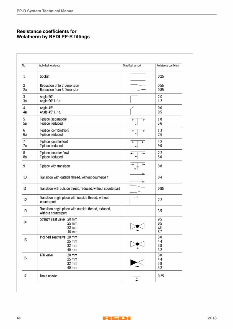
Resistance coefficients forWefatherm by REDI PP-R fittings
472013
PP-R System Technical Manual
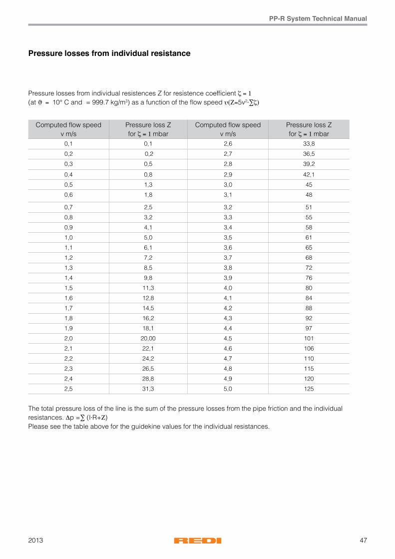
Pressure losses from individual resistance
Pressure losses from individual resistences Z for resistence coefficient ζ = 1(at ϑ = 10° C and = 999.7 kg/m3) as a function of the flow speed υ(Z=5v2⋅∑ζ)
The total pressure loss of the line is the sum of the pressure losses from the pipe friction and the individual resistances. Δp =∑ (I⋅R+Z)Please see the table above for the guidekine values for the individual resistances.
Computed flow speed v m/s
Pressure loss Z for ζ = 1 mbar
Computed flow speed v m/s
Pressure loss Z for ζ = 1 mbar
0,1 0,1 2,6 33,8
0,2 0,2 2,7 36,5
0,3 0,5 2,8 39,2
0,4 0,8 2,9 42,1
0,5 1,3 3,0 45
0,6 1,8 3,1 48
0,7 2,5 3,2 51
0,8 3,2 3,3 55
0,9 4,1 3,4 58
1,0 5,0 3,5 61
1,1 6,1 3,6 65
1,2 7,2 3,7 68
1,3 8,5 3,8 72
1,4 9,8 3,9 76
1,5 11,3 4,0 80
1,6 12,8 4,1 84
1,7 14,5 4,2 88
1,8 16,2 4,3 92
1,9 18,1 4,4 97
2,0 20,00 4,5 101
2,1 22,1 4,6 106
2,2 24,2 4,7 110
2,3 26,5 4,8 115
2,4 28,8 4,9 120
2,5 31,3 5,0 125
201348
PP-R System Technical Manual
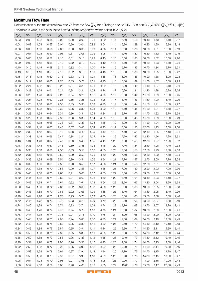
Maximum Flow RateDetermination of the maximum flow rate Vs from the flow ∑VR for buildings acc. to DIN 1988 part 3-VS=0,682·(∑VR)
0,45 -0,14[l/s]This table is valid, if the calculated flow VR of the respective water points in < 0,5 l/s.
∑VR Vs ∑VR Vs ∑VR Vs ∑VR Vs ∑VR Vs ∑VR Vs ∑VR Vs ∑VR Vs0,03 0,00 1,02 0,55 2,02 0,80 3,02 0,98 4,02 1,14 5,10 1,28 10,10 1,79 15,10 2,17
0,04 0,02 1,04 0,55 2,04 0,80 3,04 0,98 4,04 1,14 5,20 1,29 10,20 1,80 15,20 2,18
0,06 0,05 1,06 0,56 2,06 0,80 3,06 0,99 4,06 1,14 5,30 1,30 10,30 1,81 15,30 2,19
0,07 0,07 1,08 0,57 2,08 0,81 3,08 0,99 4,08 1,14 5,40 1,32 10,40 1,82 15,40 2,19
0,08 0,08 1,10 0,57 2,10 0,81 3,10 0,99 4,10 1,15 5,50 1,33 10,50 1,82 15,50 2,20
0,09 0,09 1,12 0,58 2,12 0,82 3,12 1,00 4,12 1,15 5,60 1,34 10,60 1,83 15,60 2,21
0,10 0,10 1,14 0,58 2,14 0,82 3,14 1,00 4,14 1,15 5,70 1,35 10,70 1,84 15,70 2,21
0,13 0,13 1,16 0,59 2,16 0,82 3,16 1,00 4,16 1,16 5,80 1,36 10,80 1,85 15,80 2,22
0,15 0,15 1,18 0,59 2,18 0,83 3,18 1,01 4,18 1,16 5,90 1,38 10,90 1,86 15,90 2,23
0,20 0,19 1,20 0,60 2,20 0,83 3,20 1,01 4,20 1,16 6,00 1,39 11,00 1,87 16,00 2,23
0,22 0,21 1,22 0,61 2,22 0,84 3,22 1,01 4,22 1,16 6,10 1,40 11,10 1,87 16,10 2,24
0,24 0,22 1,24 0,61 2,24 0,84 3,24 1,02 4,24 1,17 6,20 1,41 11,20 1,88 16,20 2,25
0,26 0,23 1,26 0,62 2,26 0,84 3,26 1,02 4,26 1,17 6,30 1,42 11,30 1,89 16,30 2,25
0,28 0,24 1,28 0,62 2,28 0,85 3,28 1,02 4,28 1,17 6,40 1,43 11,40 1,90 16,40 2,26
0,30 0,26 1,30 0,63 2,30 0,85 3,30 1,03 4,30 1,17 6,50 1,44 11,50 1,91 16,50 2,27
0,32 0,27 1,32 0,63 2,32 0,86 3,32 1,03 4,32 1,18 6,60 1,45 11,60 1,91 16,60 2,27
0,34 0,28 1,34 0,64 2,34 0,86 3,34 1,03 4,34 1,18 6,70 1,47 11,70 1,92 16,70 2,28
0,36 0,29 1,36 0,64 2,36 0,86 3,36 1,04 4,36 1,18 6,80 1,48 11,80 1,93 16,80 2,29
0,38 0,30 1,38 0,65 2,38 0,87 3,38 1,04 4,38 1,19 6,90 1,49 11,90 1,94 16,90 2,29
0,40 0,31 1,40 0,65 2,40 0,87 3,40 1,04 4,40 1,19 7,00 1,50 12,00 1,95 17,00 2,30
0,42 0,32 1,42 0,66 2,42 0,88 3,42 1,05 4,42 1,19 7,10 1,51 12,10 1,95 17,10 2,31
0,44 0,33 1,44 0,66 2,44 0,88 3,44 1,05 4,44 1,19 7,20 1,52 12,20 1,96 17,20 2,31
0,46 0,34 1,46 0,67 2,46 0,88 3,46 1,05 4,46 1,20 7,30 1,53 12,30 1,97 17,30 2,32
0,48 0,35 1,48 0,67 2,48 0,89 3,48 1,06 4,48 1,20 7,40 1,54 12,40 1,98 17,40 2,33
0,50 0,36 1,50 0,68 2,50 0,89 3,50 1,06 4,50 1,20 7,50 1,55 12,50 1,99 17,50 2,33
0,52 0,37 1,52 0,68 2,52 0,89 3,52 1,06 4,52 1,20 7,60 1,56 12,60 1,99 17,60 2,34
0,54 0,38 1,54 0,69 2,54 0,90 3,54 1,06 4,54 1,21 7,70 1,57 12,70 2,00 17,70 2,35
0,56 0,39 1,56 0,69 2,56 0,90 3,56 1,07 4,56 1,21 7,80 1,58 12,80 2,01 17,80 2,35
0,58 0,39 1,58 0,70 2,58 0,90 3,58 1,07 4,58 1,21 7,90 1,59 12,90 2,02 17,90 2,36
0,60 0,40 1,60 0,70 2,60 0,91 3,60 1,07 4,60 1,22 8,00 1,60 13,00 2,02 18,00 2,36
0,62 0,41 1,62 0,71 2,62 0,91 3,62 1,08 4,62 1,22 8,10 1,61 13,10 2,03 18,10 2,37
0,64 0,42 1,64 0,71 2,64 0,92 3,64 1,08 4,64 1,22 8,20 1,62 13,20 2,04 18,20 2,38
0,66 0,43 1,66 0,72 2,66 0,92 3,66 1,08 4,66 1,22 8,30 1,63 13,30 2,05 18,30 2,38
0,68 0,43 1,68 0,72 2,68 0,92 3,68 1,09 4,68 1,23 8,40 1,64 13,40 2,05 18,40 2,39
0,70 0,44 1,70 0,73 2,70 0,93 3,70 1,09 4,70 1,23 8,50 1,65 13,50 2,06 18,50 2,40
0,72 0,45 1,72 0,73 2,72 0,93 3,72 1,09 4,72 1,23 8,60 1,66 13,60 2,07 18,60 2,40
0,74 0,46 1,74 0,74 2,74 0,93 3,74 1,09 4,74 1,23 8,70 1,67 13,70 2,07 18,70 2,41
0,76 0,46 1,76 0,74 2,76 0,94 3,76 1,10 4,76 1,24 8,80 1,67 13,80 2,08 18,80 2,41
0,78 0,47 1,78 0,74 2,78 0,94 3,78 1,10 4,78 1,24 8,90 1,68 13,90 2,09 18,90 2,42
0,80 0,48 1,80 0,75 2,80 0,94 3,80 1,10 4,80 1,24 9,00 1,69 14,00 2,10 19,00 2,43
0,82 0,48 1,82 0,75 2,82 0,95 3,82 1,11 4,82 1,24 9,10 1,70 14,10 2,10 19,10 2,43
0,84 0,49 1,84 0,76 2,84 0,95 3,84 1,11 4,84 1,25 9,20 1,71 14,20 2,11 19,20 2,44
0,86 0,50 1,86 0,76 2,86 0,95 3,86 1,11 4,86 1,25 9,30 1,72 14,30 2,12 19,30 2,44
0,88 0,50 1,88 0,77 2,88 0,96 3,88 1,12 4,88 1,25 9,40 1,73 14,40 2,12 19,40 2,45
0,90 0,51 1,90 0,77 2,90 0,96 3,90 1,12 4,90 1,25 9,50 1,74 14,50 2,13 19,50 2,46
0,92 0,52 1,92 0,77 2,92 0,96 3,92 1,12 4,92 1,26 9,60 1,75 14,60 2,14 19,60 2,46
0,94 0,52 1,94 0,78 2,94 0,97 3,94 1,12 4,94 1,26 9,70 1,76 14,70 2,15 19,70 2,47
0,96 0,53 1,96 0,78 2,96 0,97 3,96 1,13 4,96 1,26 9,80 1,76 14,80 2,15 19,80 2,47
0,98 0,54 1,98 0,79 2,98 0,97 3,98 1,13 4,98 1,26 9,90 1,77 14,90 2,16 19,90 2,48
1,00 0,54 2,00 0,79 3,00 0,98 4,00 1,13 5,00 1,27 10,00 1,78 15,00 2,17 20,00 2,49
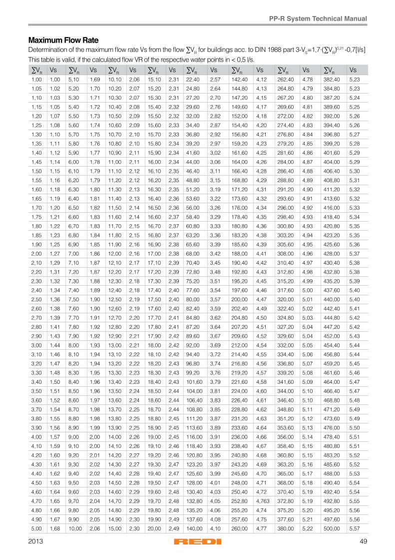
492013
PP-R System Technical Manual
Maximum Flow RateDetermination of the maximum flow rate Vs from the flow ∑VR for buildings acc. to DIN 1988 part 3-VS=1,7·(∑VR)
0,21 -0,7[l/s]This table is valid, if the calculated flow VR of the respective water points in < 0,5 l/s.
∑VR Vs ∑VR Vs ∑VR Vs ∑VR Vs ∑VR Vs ∑VR Vs ∑VR Vs ∑VR Vs1,00 1,00 5,10 1,69 10,10 2,06 15,10 2,31 22,40 2,57 142,40 4,12 262,40 4,78 382,40 5,23
1,05 1,02 5,20 1,70 10,20 2,07 15,20 2,31 24,80 2,64 144,80 4,13 264,80 4,79 384,80 5,23
1,10 1,03 5,30 1,71 10,30 2,07 15,30 2,31 27,20 2,70 147,20 4,15 267,20 4,80 387,20 5,24
1,15 1,05 5,40 1,72 10,40 2,08 15,40 2,32 29,60 2,76 149,60 4,17 269,60 4,81 389,60 5,25
1,20 1,07 5,50 1,73 10,50 2,09 15,50 2,32 32,00 2,82 152,00 4,18 272,00 4,82 392,00 5,26
1,25 1,08 5,60 1,74 10,60 2,09 15,60 2,33 34,40 2,87 154,40 4,20 274,40 4,83 394,40 5,26
1,30 1,10 5,70 1,75 10,70 2,10 15,70 2,33 36,80 2,92 156,80 4,21 276,80 4,84 396,80 5,27
1,35 1,11 5,80 1,76 10,80 2,10 15,80 2,34 39,20 2,97 159,20 4,23 279,20 4,85 399,20 5,28
1,40 1,12 5,90 1,77 10,90 2,11 15,90 2,34 41,60 3,02 161,60 4,25 281,60 4,86 401,60 5,29
1,45 1,14 6,00 1,78 11,00 2,11 16,00 2,34 44,00 3,06 164,00 4,26 284,00 4,87 404,00 5,29
1,50 1,15 6,10 1,79 11,10 2,12 16,10 2,35 46,40 3,11 166,40 4,28 286,40 4,88 406,40 5,30
1,55 1,16 6,20 1,79 11,20 2,12 16,20 2,35 48,80 3,15 168,80 4,29 288,80 4,89 408,80 5,31
1,60 1,18 6,30 1,80 11,30 2,13 16,30 2,35 51,20 3,19 171,20 4,31 291,20 4,90 411,20 5,32
1,65 1,19 6,40 1,81 11,40 2,13 16,40 2,36 53,60 3,22 173,60 4,32 293,60 4,91 413,60 5,32
1,70 1,20 6,50 1,82 11,50 2,14 16,50 2,36 56,00 3,26 176,00 4,34 296,00 4,92 416,00 5,33
1,75 1,21 6,60 1,83 11,60 2,14 16,60 2,37 58,40 3,29 178,40 4,35 298,40 4,93 418,40 5,34
1,80 1,22 6,70 1,83 11,70 2,15 16,70 2,37 60,80 3,33 180,80 4,36 300,80 4,93 420,80 5,35
1,85 1,23 6,80 1,84 11,80 2,15 16,80 2,37 63,20 3,36 183,20 4,38 303,20 4,94 423,20 5,35
1,90 1,25 6,90 1,85 11,90 2,16 16,90 2,38 65,60 3,39 185,60 4,39 305,60 4,95 425,60 5,36
2,00 1,27 7,00 1,86 12,00 2,16 17,00 2,38 68,00 3,42 188,00 4,41 308,00 4,96 428,00 5,37
2,10 1,29 7,10 1,87 12,10 2,17 17,10 2,39 70,40 3,45 190,40 4,42 310,40 4,97 430,40 5,38
2,20 1,31 7,20 1,87 12,20 2,17 17,20 2,39 72,80 3,48 192,80 4,43 312,80 4,98 432,80 5,38
2,30 1,32 7,30 1,88 12,30 2,18 17,30 2,39 75,20 3,51 195,20 4,45 315,20 4,99 435,20 5,39
2,40 1,34 7,40 1,89 12,40 2,18 17,40 2,40 77,60 3,54 197,60 4,46 317,60 5,00 437,60 5,40
2,50 1,36 7,50 1,90 12,50 2,19 17,50 2,40 80,00 3,57 200,00 4,47 320,00 5,01 440,00 5,40
2,60 1,38 7,60 1,90 12,60 2,19 17,60 2,40 82,40 3,59 202,40 4,49 322,40 5,02 442,40 5,41
2,70 1,39 7,70 1,91 12,70 2,20 17,70 2,41 84,80 3,62 204,80 4,50 324,80 5,03 444,80 5,42
2,80 1,41 7,80 1,92 12,80 2,20 17,80 2,41 87,20 3,64 207,20 4,51 327,20 5,04 447,20 5,42
2,90 1,43 7,90 1,92 12,90 2,21 17,90 2,42 89,60 3,67 209,60 4,52 329,60 5,04 452,00 5,43
3,00 1,44 8,00 1,93 13,00 2,21 18,00 2,42 92,00 3,69 212,00 4,54 332,00 5,05 454,40 5,44
3,10 1,46 8,10 1,94 13,10 2,22 18,10 2,42 94,40 3,72 214,40 4,55 334,40 5,06 456,80 5,44
3,20 1,47 8,20 1,94 13,20 2,22 18,20 2,43 96,80 3,74 216,80 4,56 336,80 5,07 459,20 5,45
3,30 1,48 8,30 1,95 13,30 2,23 18,30 2,43 99,20 3,76 219,20 4,57 339,20 5,08 461,60 5,46
3,40 1,50 8,40 1,96 13,40 2,23 18,40 2,43 101,60 3,79 221,60 4,58 341,60 5,09 464,00 5,47
3,50 1,51 8,50 1,96 13,50 2,24 18,50 2,44 104,00 3,81 224,00 4,60 344,00 5,10 466,40 5,47
3,60 1,52 8,60 1,97 13,60 2,24 18,60 2,44 106,40 3,83 226,40 4,61 346,40 5,10 468,80 5,48
3,70 1,54 8,70 1,98 13,70 2,25 18,70 2,44 108,80 3,85 228,80 4,62 348,80 5,11 471,20 5,49
3,80 1,55 8,80 1,98 13,80 2,25 18,80 2,45 111,20 3,87 231,20 4,63 351,20 5,12 473,60 5,49
3,90 1,56 8,90 1,99 13,90 2,25 18,90 2,45 113,60 3,89 233,60 4,64 353,60 5,13 476,00 5,50
4,00 1,57 9,00 2,00 14,00 2,26 19,00 2,45 116,00 3,91 236,00 4,66 356,00 5,14 478,40 5,51
4,10 1,59 9,10 2,00 14,10 2,26 19,10 2,46 118,40 3,93 238,40 4,67 358,40 5,15 480,80 5,51
4,20 1,60 9,20 2,01 14,20 2,27 19,20 2,46 120,80 3,95 240,80 4,68 360,80 5,15 483,20 5,52
4,30 1,61 9,30 2,02 14,30 2,27 19,30 2,47 123,20 3,97 243,20 4,69 363,20 5,16 485,60 5,52
4,40 1,62 9,40 2,02 14,40 2,28 19,40 2,47 125,60 3,99 245,60 4,70 365,00 5,17 488,00 5,53
4,50 1,63 9,50 2,03 14,50 2,28 19,50 2,47 128,00 4,01 248,00 4,71 368,00 5,18 490,40 5,54
4,60 1,64 9,60 2,03 14,60 2,29 19,60 2,48 130,40 4,03 250,40 4,72 370,40 5,19 492,40 5,54
4,70 1,65 9,70 2,04 14,70 2,29 19,70 2,48 132,80 4,05 252,80 4,763 372,80 5,19 492,80 5,55
4,80 1,66 9,80 2,05 14,80 2,29 19,80 2,48 135,20 4,06 255,20 4,74 375,20 5,20 495,20 5,56
4,90 1,67 9,90 2,05 14,90 2,30 19,90 2,49 137,60 4,08 257,60 4,75 377,60 5,21 497,60 5,56
5,00 1,68 10,00 2,06 15,00 2,30 20,00 2,49 140,00 4,10 260,00 4,77 380,00 5,22 500,00 5,57
201350
PP-R System Technical Manual
dxsV°
s 16x2,710,6mm
20x3,413,2mm
25x4,216,6mm
32x5,421,2mm
40x6,726,6mm
50x8,333,4mm
63x10,542mm
75x12,550mm
90x15,060mm
110x18,373,4mm
125x20,883,4mm
0,01 R 0,379 0,138 0,048 0,016 0,006 0,002 0,001 0,000 0,000 0,000 0,000
v 0,113 0,073 0,046 0,028 0,018 0,011 0,007 0,005 0,004 0,002 0,002
0,02 R 1,182 0,425 0,146 0,047 0,017 0,006 0,002 0,001 0,000 0,000 0,000
v 0,227 0,146 0,092 0,057 0,036 0,023 0,014 0,010 0,007 0,005 0,004
0,03 R 2,334 0,833 0,285 0,091 0,032 0,011 0,004 0,002 0,001 0,000 0,000
v 0,340 0,219 0,139 0,085 0,054 0,034 0,022 0,015 0,011 0,007 0,005
0,04 R 3,806 1,352 0,461 0,147 0,051 0,018 0,006 0,003 0,001 0,000 0,000
v 0,453 0,292 0,185 0,113 0,072 0,046 0,029 0,020 0,014 0,009 0,007
0,05 R 5,581 1,976 0,671 0,213 0,074 0,026 0,009 0,004 0,002 0,001 0,000
v 0,567 0,365 0,231 0,142 0,090 0,057 0,036 0,025 0,018 0,012 0,009
0,06 R 7,645 2,699 0,914 0,289 0,100 0,035 0,012 0,005 0,002 0,001 0,001
v 0,680 0,438 0,277 0,170 0,108 0,068 0,043 0,031 0,021 0,014 0,011
0,07 R 9,990 3,518 1,189 0,375 0,129 0,045 0,015 0,007 0,003 0,001 0,001
v 0,793 0,512 0,323 0,198 0,126 0,080 0,051 0,036 0,025 0,017 0,013
0,08 R 12,609 4,431 1,494 0,471 0,162 0,056 0,019 0,008 0,004 0,001 0,001
v 0,907 0,585 0,370 0,227 0,144 0,091 0,058 0,041 0,028 0,019 0,015
0,09 R 15,496 5,436 1,830 0,576 0,198 0,068 0,023 0,010 0,004 0,002 0,001
v 1,020 0,658 0,416 0,255 0,162 0,103 0,065 0,046 0,032 0,021 0,016
0,10 R 18,648 6,530 2,195 0,689 0,236 0,081 0,028 0,012 0,005 0,002 0,001
v 1,133 0,731 0,462 0,283 0,180 0,114 0,072 0,051 0,035 0,024 0,018
0,12 R 25,726 8,980 3,010 0,943 0,322 0,110 0,038 0,017 0,007 0,003 0,002
v 1,360 0,877 0,554 0,340 0,216 0,137 0,087 0,061 0,042 0,028 0,022
0,14 R 33,819 11,774 3,936 1,230 0,420 0,143 0,049 0,022 0,009 0,004 0,002
v 1,586 1,023 0,647 0,397 0,252 0,160 0,101 0,071 0,050 0,033 0,026
0,16 R 42,908 14,902 4,971 1,550 0,528 0,180 0,061 0,027 0,011 0,004 0,002
v 1,813 1,169 0,739 0,453 0,288 0,183 0,115 0,081 0,057 0,038 0,029
0,18 R 52,978 18,358 6,111 1,902 0,647 0,220 0,075 0,033 0,014 0,005 0,003
v 2,040 1,315 0,832 0,510 0,324 0,205 0,130 0,092 0,064 0,043 0,033
0,20 R 64,016 22,138 7,356 2,286 0,777 0,264 0,090 0,039 0,017 0,007 0,004
v 2,266 1,461 0,924 0,567 0,360 0,228 0,144 0,102 0,071 0,047 0,037
0,30 R 133,423 45,764 15,094 4,658 1,574 0,533 0,180 0,079 0,033 0,013 0,007
v 3,400 2,192 1,386 0,850 0,540 0,342 0,217 0,153 0,106 0,071 0,055
0,40 R 226,000 77,035 25,263 7,755 2,610 0,880 0,296 0,129 0,055 0,021 0,012
v 4,533 2,923 1,848 1,133 0,720 0,457 0,289 0,204 0,141 0,095 0,073
0,50 R 341,300 115,750 37,782 11,549 3,874 1,302 0,437 0,191 0,080 0,031 0,017
v 5,666 3,654 2,310 1,416 0,900 0,571 0,361 0,255 0,177 0,118 0,092
0,60 R 479,050 161,783 52,598 16,018 5,357 1,796 0,601 0,262 0,110 0,042 0,023
v 6,799 4,384 2,772 1,700 1,080 0,685 0,433 0,306 0,212 0,142 0,110
0,70 R 639,073 215,047 69,672 21,150 7,056 2,360 0,788 0,343 0,144 0,055 0,030
v 7,932 5,115 3,234 1,983 1,260 0,799 0,505 0,357 0,248 0,165 0,128
0,80 R 821,24 275,48 88,98 26,93 8,96 2,99 1,00 0,43 0,18 0,07 0,04
v 9,07 5,85 3,70 2,27 1,44 0,91 0,58 0,41 0,28 0,19 0,15
Pipe friction gradient/flow speed Wefatherm by REDI pipes SDR 6Pipe friction gradient R and calculated flow speed in dependence of circulation V°
Roughness: K=0,007 mm sp. density: ρ=998,00 kg/m3
Temperature: t=20 °C kin. tenacity: ν=1,02 x 10⁻⁶ m2/s
V° = circulation (l/s) R = pressure gradient [mbar/m] v = speed
512013
PP-R System Technical Manual
dxsV°
s 16x2,710,6mm
20x3,413,2mm
25x4,216,6mm
32x5,421,2mm
40x6,726,6mm
50x8,333,4mm
63x10,542mm
75x12,550mm
90x15,060mm
110x18,373,4mm
125x20,883,4mm
0,90 R 1025,46 343,03 110,49 33,36 11,08 3,69 1,23 0,53 0,22 0,09 0,05
v 10,20 6,58 4,16 2,55 1,62 1,03 0,65 0,46 0,32 0,21 0,16
1,00 R 1251,65 417,67 134,20 40,41 13,40 4,46 1,48 0,64 0,27 0,10 0,06
v 11,33 7,31 4,62 2,83 1,80 1,14 0,72 0,51 0,35 0,24 0,18
1,20 R 1769,77 588,09 188,13 56,42 18,64 6,18 2,05 0,89 0,37 0,14 0,08
v 13,60 8,77 5,54 3,40 2,16 1,37 0,87 0,61 0,42 0,28 0,22
1,40 R 2375,27 786,55 250,70 74,90 24,67 8,16 2,70 1,17 0,49 0,19 0,10
v 15,86 10,23 6,47 3,97 2,52 1,60 1,01 0,71 0,50 0,33 0,26
1,60 R 3067,91 1012,94 321,83 95,84 31,48 10,39 3,43 1,48 0,62 0,24 0,13
v 18,13 11,69 7,39 4,53 2,88 1,83 1,15 0,81 0,57 0,38 0,29
1,80 R 3847,53 1267,17 401,49 119,22 39,06 12,87 4,24 1,83 0,76 0,29 0,16
v 20,40 13,15 8,32 5,10 3,24 2,05 1,30 0,92 0,64 0,43 0,33
2,00 R 4714,01 1549,16 489,64 145,02 47,41 15,58 5,13 2,21 0,92 0,35 0,19
v 22,66 14,61 9,24 5,67 3,60 2,28 1,44 1,02 0,71 0,47 0,37
2,20 R 5667,26 1858,87 586,25 173,22 56,51 18,54 6,09 2,62 1,09 0,41 0,22
v 24,93 16,08 10,17 6,23 3,96 2,51 1,59 1,12 0,78 0,52 0,40
2,40 R 6707,20 2196,26 691,30 203,82 66,37 21,74 7,13 3,07 1,27 0,48 0,26
v 27,20 17,54 11,09 6,80 4,32 2,74 1,73 1,22 0,85 0,57 0,44
2,60 R 7833,77 2561,28 804,77 236,81 76,98 25,17 8,24 3,54 1,47 0,56 0,30
v 29,46 19,00 12,01 7,37 4,68 2,97 1,88 1,32 0,92 0,61 0,48
2,80 R 9046,91 2953,91 926,64 272,18 88,33 28,84 9,43 4,05 1,68 0,64 0,34
v 31,73 20,46 12,94 7,93 5,04 3,20 2,02 1,43 0,99 0,66 0,51
3,00 R 10346,59 3374,13 1056,91 309,92 100,42 32,75 10,70 4,59 1,90 0,72 0,39
v 34,00 21,92 13,86 8,50 5,40 3,42 2,17 1,53 1,06 0,71 0,55
3,20 R 11732,76 3821,92 1195,56 350,03 113,26 36,88 12,03 5,16 2,13 0,81 0,44
v 36,26 23,38 14,79 9,07 5,76 3,65 2,31 1,63 1,13 0,76 0,59
3,40 R 13205,40 4297,25 1342,57 392,50 126,83 41,25 13,44 5,76 2,38 0,90 0,49
v 38,53 24,85 15,71 9,63 6,12 3,88 2,45 1,73 1,20 0,80 0,62
3,60 R 14764,48 4800,12 1497,96 437,33 141,13 45,85 14,92 6,39 2,64 1,00 0,54
v 40,79 26,31 16,63 10,20 6,48 4,11 2,60 1,83 1,27 0,85 0,66
3,80 R 16409,98 5330,50 1661,69 484,52 156,17 50,67 16,48 7,05 2,91 1,10 0,59
v 43,06 27,77 17,56 10,77 6,84 4,34 2,74 1,94 1,34 0,90 0,70
4,00 R 18141,87 5888,40 1833,78 534,06 171,94 55,73 18,10 7,74 3,19 1,21 0,65
v 45,33 29,23 18,48 11,33 7,20 4,57 2,89 2,04 1,41 0,95 0,73
4,20 R 19960,13 6473,79 2014,21 585,95 188,45 61,02 19,80 8,46 3,49 1,32 0,71
v 47,59 30,69 19,41 11,90 7,56 4,79 3,03 2,14 1,49 0,99 0,77
4,40 R 21864,75 7086,67 2202,99 640,19 205,68 66,53 21,57 9,21 3,80 1,43 0,77
v 49,86 32,15 20,33 12,46 7,92 5,02 3,18 2,24 1,56 1,04 0,81
4,60 R 23855,72 7727,03 2400,09 696,77 223,63 72,27 23,41 9,99 4,12 1,55 0,84
v 52,13 33,61 21,25 13,03 8,28 5,25 3,32 2,34 1,63 1,09 0,84
4,80 R 25933,02 8394,86 2605,53 755,69 242,32 78,23 25,32 10,79 4,45 1,68 0,90
v 54,39 35,08 22,18 13,60 8,64 5,48 3,46 2,44 1,70 1,13 0,88
Pipe friction gradient/flow speed Wefatherm by REDI pipes SDR 6Pipe friction gradient R and calculated flow speed in dependence of circulation V°
Roughness: K=0,007 mm sp. density: ρ=998,00 kg/m3
Temperature: t=20 °C kin. tenacity: ν=1,02 x 10⁻⁶ m2/s
V° = circulation (l/s) R = pressure gradient [mbar/m] v = speed
201352
PP-R System Technical Manual
dxsV°
s 16x2,710,6mm
20x3,413,2mm
25x4,216,6mm
32x5,421,2mm
40x6,726,6mm
50x8,333,4mm
63x10,542mm
75x12,550mm
90x15,060mm
110x18,373,4mm
125x20,883,4mm
5,00 R 28096,63 9090,16 2819,29 816,96 261,73 84,43 27,30 11,63 4,79 1,80 0,97
v 56,66 36,54 23,10 14,16 9,00 5,71 3,61 2,55 1,77 1,18 0,92
5,20 R 30346,55 9812,92 3041,38 880,56 281,87 90,84 29,36 12,50 5,14 1,94 1,04
v 58,93 38,00 24,03 14,73 9,36 5,93 3,75 2,65 1,84 1,23 0,95
5,40 R 32682,77 10563,14 3271,78 946,50 302,73 97,49 31,48 13,40 5,51 2,07 1,12
v 61,19 39,46 24,95 15,30 9,72 6,16 3,90 2,75 1,91 1,28 0,99
5,60 R 35105,27 11340,80 3510,51 1014,78 324,31 104,35 33,67 14,32 5,89 2,21 1,19
v 63,46 40,92 25,88 15,86 10,08 6,39 4,04 2,85 1,98 1,32 1,03
5,80 R 37614,05 12145,91 3757,55 1085,39 346,61 111,44 35,93 15,28 6,28 2,36 1,27
v 65,72 42,38 26,80 16,43 10,44 6,62 4,19 2,95 2,05 1,37 1,06
6,00 R 40209,09 12978,46 4012,90 1158,33 369,64 118,76 38,26 16,26 6,68 2,51 1,35
v 67,99 43,84 27,72 17,00 10,80 6,85 4,33 3,06 2,12 1,42 1,10
6,20 R 42890,40 13838,44 4276,56 1233,61 393,39 126,30 40,67 17,27 7,09 2,66 1,44
v 70,26 45,31 28,65 17,56 11,16 7,08 4,48 3,16 2,19 1,47 1,13
6,40 R 45657,96 14725,85 4548,53 1311,21 417,85 134,06 43,14 18,31 7,52 2,82 1,52
v 72,52 46,77 29,57 18,13 11,52 7,30 4,62 3,26 2,26 1,51 1,17
6,60 R 48511,77 15640,70 4828,80 1391,15 443,04 142,05 45,68 19,38 7,95 2,98 1,61
v 74,79 48,23 30,50 18,70 11,88 7,53 4,76 3,36 2,33 1,56 1,21
6,80 R 51451,83 16582,97 5117,38 1473,41 468,95 150,26 48,29 20,48 8,40 3,15 1,70
v 77,06 49,69 31,42 19,26 12,24 7,76 4,91 3,46 2,41 1,61 1,24
7,00 R 54478,11 17552,66 5414,27 1558,01 495,58 158,69 50,96 21,61 8,86 3,32 1,79
v 79,32 51,15 32,34 19,83 12,60 7,99 5,05 3,57 2,48 1,65 1,28
7,50 R 62421,08 20096,83 6192,79 1779,67 565,28 180,74 57,96 24,55 10,05 3,77 2,03
v 84,99 54,81 34,65 21,25 13,50 8,56 5,41 3,82 2,65 1,77 1,37
8,00 R 70902,90 22812,34 7023,17 2015,86 639,48 204,18 65,39 27,67 11,32 4,24 2,28
v 90,65 58,46 36,96 22,66 14,40 9,13 5,77 4,07 2,83 1,89 1,46
9,00 R 89482,88 28757,21 8839,45 2531,81 801,30 255,21 81,52 34,44 14,06 5,25 2,82
v 101,99 65,77 41,58 25,50 16,20 10,27 6,50 4,58 3,18 2,13 1,65
10,00 R 10862,98 3105,78 980,99 311,75 99,36 41,90 17,08 6,37 3,42
v 46,21 28,33 17,99 11,41 7,22 5,09 3,54 2,36 1,83
Pipe friction gradient/flow speed Wefatherm by REDI pipes SDR 6Pipe friction gradient R and calculated flow speed in dependence of circulation V°
Roughness: K=0,007 mm sp. density: ρ=998,00 kg/m3
Temperature: t=20 °C kin. tenacity: ν=1,02 x 10⁻⁶ m2/s
V° = circulation (l/s) R = pressure gradient [mbar/m] v = speed

532013
PP-R System Technical Manual
dxsV°
s 16x2,710,6mm
20x3,413,2mm
25x4,216,6mm
32x5,421,2mm
40x6,726,6mm
50x8,333,4mm
63x10,542mm
75x12,550mm
90x15,060mm
110x18,373,4mm
125x20,883,4mm
0,01 R 0,283 0,102 0,035 0,011 0,004 0,001 0,000 0,000 0,000 0,000 0,000
v 0,113 0,073 0,046 0,028 0,018 0,011 0,007 0,005 0,004 0,002 0,002
0,02 R 0,916 0,325 0,111 0,035 0,012 0,004 0,001 0,001 0,000 0,000 0,000
v 0,227 0,146 0,092 0,057 0,036 0,023 0,014 0,010 0,007 0,005 0,004
0,03 R 1,842 0,650 0,220 0,069 0,024 0,008 0,003 0,001 0,001 0,000 0,000
v 0,340 0,219 0,139 0,085 0,054 0,034 0,022 0,015 0,011 0,007 0,005
0,04 R 3,043 1,068 0,360 0,113 0,039 0,013 0,005 0,002 0,001 0,000 0,000
v 0,453 0,292 0,185 0,113 0,072 0,046 0,029 0,020 0,014 0,009 0,007
0,05 R 4,504 1,575 0,529 0,166 0,057 0,019 0,007 0,003 0,001 0,000 0,000
v 0,567 0,365 0,231 0,142 0,090 0,057 0,036 0,025 0,018 0,012 0,009
0,06 R 6,219 2,168 0,726 0,227 0,078 0,027 0,009 0,004 0,002 0,001 0,000
v 0,680 0,438 0,277 0,170 0,108 0,068 0,043 0,031 0,021 0,014 0,011
0,07 R 8,182 2,844 0,950 0,296 0,101 0,034 0,012 0,005 0,002 0,001 0,000
v 0,793 0,512 0,323 0,198 0,126 0,080 0,051 0,036 0,025 0,017 0,013
0,08 R 10,387 3,602 1,200 0,374 0,127 0,043 0,015 0,006 0,003 0,001 0,001
v 0,907 0,585 0,370 0,227 0,144 0,091 0,058 0,041 0,028 0,019 0,015
0,09 R 12,832 4,440 1,476 0,459 0,156 0,053 0,018 0,008 0,003 0,001 0,001
v 1,020 0,658 0,416 0,255 0,162 0,103 0,065 0,046 0,032 0,021 0,016
0,10 R 15,513 5,356 1,777 0,551 0,187 0,064 0,022 0,009 0,004 0,002 0,001
v 1,133 0,731 0,462 0,283 0,180 0,114 0,072 0,051 0,035 0,024 0,018
0,12 R 21,576 7,422 2,455 0,759 0,257 0,087 0,029 0,013 0,005 0,002 0,001
v 1,360 0,877 0,554 0,340 0,216 0,137 0,087 0,061 0,042 0,028 0,022
0,14 R 28,562 9,794 3,230 0,996 0,337 0,114 0,038 0,017 0,007 0,003 0,002
v 1,586 1,023 0,647 0,397 0,252 0,160 0,101 0,071 0,050 0,033 0,026
0,16 R 36,458 12,466 4,100 1,262 0,426 0,144 0,048 0,021 0,009 0,003 0,002
v 1,813 1,169 0,739 0,453 0,288 0,183 0,115 0,081 0,057 0,038 0,029
0,18 R 45,258 15,435 5,064 1,555 0,524 0,177 0,059 0,026 0,011 0,004 0,002
v 2,040 1,315 0,832 0,510 0,324 0,205 0,130 0,092 0,064 0,043 0,033
0,20 R 54,953 18,697 6,121 1,876 0,631 0,212 0,071 0,031 0,013 0,005 0,003
v 2,266 1,461 0,924 0,567 0,360 0,228 0,144 0,102 0,071 0,047 0,037
0,30 R 116,717 39,342 12,767 3,882 1,296 0,434 0,145 0,063 0,027 0,010 0,006
v 3,400 2,192 1,386 0,850 0,540 0,342 0,217 0,153 0,106 0,071 0,055
0,40 R 200,365 67,082 21,626 6,534 2,172 0,724 0,241 0,105 0,044 0,017 0,009
v 4,533 2,923 1,848 1,133 0,720 0,457 0,289 0,204 0,141 0,095 0,073
0,50 R 305,693 101,815 32,650 9,814 3,248 1,079 0,358 0,155 0,065 0,025 0,014
v 5,666 3,654 2,310 1,416 0,900 0,571 0,361 0,255 0,177 0,118 0,092
0,60 R 432,584 143,479 45,811 13,711 4,522 1,498 0,496 0,215 0,090 0,034 0,019
v 6,799 4,384 2,772 1,700 1,080 0,685 0,433 0,306 0,212 0,142 0,110
0,70 R 580,963 192,035 61,089 18,215 5,989 1,979 0,654 0,282 0,118 0,045 0,024
v 7,932 5,115 3,234 1,983 1,260 0,799 0,505 0,357 0,248 0,165 0,128
0,80 R 750,78 247,45 78,47 23,32 7,65 2,52 0,83 0,36 0,15 0,06 0,03
v 9,07 5,85 3,70 2,27 1,44 0,91 0,58 0,41 0,28 0,19 0,15
Pipe friction gradient/flow speed Wefatherm by REDI pipes SDR 6Pipe friction gradient R and calculated flow speed in dependence of circulation V°
Roughness: K=0,007 mm sp. density: ρ=983,20 kg/m3
Temperature: t=60 °C kin. tenacity: ν=0,47 x 10⁻⁶ m2/s
V° = circulation (l/s) R = pressure gradient [mbar/m] v = speed

201354
PP-R System Technical Manual
dxsV°
s 16x2,710,6mm
20x3,413,2mm
25x4,216,6mm
32x5,421,2mm
40x6,726,6mm
50x8,333,4mm
63x10,542mm
75x12,550mm
90x15,060mm
110x18,373,4mm
125x20,883,4mm
0,90 R 942,00 309,72 97,95 29,03 9,49 3,12 1,03 0,44 0,18 0,07 0,04
v 10,20 6,58 4,16 2,55 1,62 1,03 0,65 0,46 0,32 0,21 0,16
1,00 R 1154,59 378,81 119,51 35,32 11,53 3,78 1,24 0,53 0,22 0,08 0,05
v 11,33 7,31 4,62 2,83 1,80 1,14 0,72 0,51 0,35 0,24 0,18
1,20 R 1643,83 537,44 168,86 49,69 16,15 5,28 1,73 0,74 0,31 0,12 0,06
v 13,60 8,77 5,54 3,40 2,16 1,37 0,87 0,61 0,42 0,28 0,22
1,40 R 2218,35 723,27 226,49 66,39 21,51 7,01 2,29 0,98 0,41 0,15 0,08
v 15,86 10,23 6,47 3,97 2,52 1,60 1,01 0,71 0,50 0,33 0,26
1,60 R 2878,09 936,25 292,39 85,44 27,59 8,97 2,92 1,25 0,52 0,20 0,11
v 18,13 11,69 7,39 4,53 2,88 1,83 1,15 0,81 0,57 0,38 0,29
1,80 R 3622,98 1176,36 366,51 106,80 34,40 11,16 3,63 1,55 0,64 0,24 0,13
v 20,40 13,15 8,32 5,10 3,24 2,05 1,30 0,92 0,64 0,43 0,33
2,00 R 4452,97 1443,56 448,86 130,48 41,93 13,57 4,40 1,88 0,77 0,29 0,16
v 22,66 14,61 9,24 5,67 3,60 2,28 1,44 1,02 0,71 0,47 0,37
2,20 R 5368,02 1737,83 539,42 156,47 50,18 16,20 5,24 2,24 0,92 0,35 0,19
v 24,93 16,08 10,17 6,23 3,96 2,51 1,59 1,12 0,78 0,52 0,40
2,40 R 6368,12 2059,16 638,19 184,77 59,14 19,06 6,16 2,62 1,08 0,41 0,22
v 27,20 17,54 11,09 6,80 4,32 2,74 1,73 1,22 0,85 0,57 0,44
2,60 R 7453,23 2407,55 745,15 215,37 68,82 22,14 7,14 3,04 1,25 0,47 0,25
v 29,46 19,00 12,01 7,37 4,68 2,97 1,88 1,32 0,92 0,61 0,48
2,80 R 8623,34 2782,96 860,31 248,27 79,20 25,44 8,19 3,48 1,43 0,54 0,29
v 31,73 20,46 12,94 7,93 5,04 3,20 2,02 1,43 0,99 0,66 0,51
3,00 R 9878,43 3185,41 983,65 283,46 90,30 28,96 9,32 3,95 1,62 0,61 0,33
v 34,00 21,92 13,86 8,50 5,40 3,42 2,17 1,53 1,06 0,71 0,55
3,20 R 11218,48 3614,87 1115,17 320,95 102,11 32,70 10,50 4,45 1,83 0,68 0,37
v 36,26 23,38 14,79 9,07 5,76 3,65 2,31 1,63 1,13 0,76 0,59
3,40 R 12643,49 4071,35 1254,87 360,73 114,62 36,66 11,76 4,98 2,04 0,76 0,41
v 38,53 24,85 15,71 9,63 6,12 3,88 2,45 1,73 1,20 0,80 0,62
3,60 R 14153,44 4554,84 1402,75 402,81 127,84 40,84 13,09 5,54 2,27 0,85 0,46
v 40,79 26,31 16,63 10,20 6,48 4,11 2,60 1,83 1,27 0,85 0,66
3,80 R 15748,32 5065,33 1558,80 447,17 141,77 45,24 14,48 6,12 2,50 0,94 0,50
v 43,06 27,77 17,56 10,77 6,84 4,34 2,74 1,94 1,34 0,90 0,70
4,00 R 17428,12 5602,81 1723,02 493,82 156,40 49,85 15,94 6,74 2,75 1,03 0,55
v 45,33 29,23 18,48 11,33 7,20 4,57 2,89 2,04 1,41 0,95 0,73
4,20 R 19192,84 6167,29 1895,41 542,76 171,74 54,68 17,46 7,38 3,01 1,12 0,60
v 47,59 30,69 19,41 11,90 7,56 4,79 3,03 2,14 1,49 0,99 0,77
4,40 R 21042,47 6758,77 2075,96 593,99 187,78 59,73 19,06 8,04 3,28 1,23 0,66
v 49,86 32,15 20,33 12,46 7,92 5,02 3,18 2,24 1,56 1,04 0,81
4,60 R 22977,01 7377,22 2264,68 647,50 204,53 65,00 20,72 8,74 3,56 1,33 0,71
v 52,13 33,61 21,25 13,03 8,28 5,25 3,32 2,34 1,63 1,09 0,84
4,80 R 24996,44 8022,67 2461,56 703,30 221,98 70,48 22,44 9,46 3,85 1,44 0,77
v 54,39 35,08 22,18 13,60 8,64 5,48 3,46 2,44 1,70 1,13 0,88
Pipe friction gradient/flow speed Wefatherm by REDI pipes SDR 6Pipe friction gradient R and calculated flow speed in dependence of circulation V°
Roughness: K=0,007 mm sp. density: ρ=983,20 kg/m3
Temperature: t=60 °C kin. tenacity: ν=0,47 x 10⁻⁶ m2/s
V° = circulation (l/s) R = pressure gradient [mbar/m] v = speed

552013
PP-R System Technical Manual
dxsV°
s 16x2,710,6mm
20x3,413,2mm
25x4,216,6mm
32x5,421,2mm
40x6,726,6mm
50x8,333,4mm
63x10,542mm
75x12,550mm
90x15,060mm
110x18,373,4mm
125x20,883,4mm
5,00 R 27100,76 8695,09 2666,61 761,38 240,13 76,18 24,24 10,21 4,16 1,55 0,83
v 56,66 36,54 23,10 14,16 9,00 5,71 3,61 2,55 1,77 1,18 0,92
5,20 R 29289,97 9394,50 2879,81 821,75 258,99 82,10 26,10 10,99 4,47 1,66 0,89
v 58,93 38,00 24,03 14,73 9,36 5,93 3,75 2,65 1,84 1,23 0,95
5,40 R 31564,07 10120,88 3101,18 884,39 278,54 88,23 28,03 11,79 4,80 1,78 0,96
v 61,19 39,46 24,95 15,30 9,72 6,16 3,90 2,75 1,91 1,28 0,99
5,60 R 33923,04 10874,23 3330,70 949,32 298,81 94,58 30,02 12,62 5,13 1,91 1,02
v 63,46 40,92 25,88 15,86 10,08 6,39 4,04 2,85 1,98 1,32 1,03
5,80 R 36366,89 11654,56 3568,38 1016,53 319,77 101,15 32,08 13,48 5,48 2,04 1,09
v 65,72 42,38 26,80 16,43 10,44 6,62 4,19 2,95 2,05 1,37 1,06
6,00 R 38895,61 12461,86 3814,22 1086,03 341,43 107,93 34,21 14,37 5,83 2,17 1,16
v 67,99 43,84 27,72 17,00 10,80 6,85 4,33 3,06 2,12 1,42 1,10
6,20 R 41509,20 13296,13 4068,21 1157,80 363,80 114,93 36,40 15,28 6,20 2,30 1,23
v 70,26 45,31 28,65 17,56 11,16 7,08 4,48 3,16 2,19 1,47 1,13
6,40 R 44207,65 14157,37 4330,36 1231,85 386,86 122,14 38,66 16,22 6,58 2,44 1,31
v 72,52 46,77 29,57 18,13 11,52 7,30 4,62 3,26 2,26 1,51 1,17
6,60 R 46990,97 15045,58 4600,66 1308,19 410,63 129,57 40,98 17,19 6,97 2,59 1,38
v 74,79 48,23 30,50 18,70 11,88 7,53 4,76 3,36 2,33 1,56 1,21
6,80 R 49859,14 15960,75 4879,12 1386,80 435,10 137,21 43,37 18,18 7,37 2,73 1,46
v 77,06 49,69 31,42 19,26 12,24 7,76 4,91 3,46 2,41 1,61 1,24
7,00 R 52812,18 16902,88 5165,73 1467,70 460,27 145,07 45,83 19,20 7,78 2,88 1,54
v 79,32 51,15 32,34 19,83 12,60 7,99 5,05 3,57 2,48 1,65 1,28
7,50 R 60566,00 19376,18 5917,91 1679,90 526,26 165,66 52,26 21,87 8,85 3,28 1,75
v 84,99 54,81 34,65 21,25 13,50 8,56 5,41 3,82 2,65 1,77 1,37
8,00 R 68850,13 22017,98 6721,04 1906,35 596,62 187,59 59,10 24,71 9,99 3,69 1,97
v 90,65 58,46 36,96 22,66 14,40 9,13 5,77 4,07 2,83 1,89 1,46
9,00 R 87009,21 27807,02 8480,10 2401,94 750,46 235,48 74,02 30,89 12,46 4,60 2,45
v 101,99 65,77 41,58 25,50 16,20 10,27 6,50 4,58 3,18 2,13 1,65
10,00 R 10442,86 2954,47 921,79 288,73 90,57 37,73 15,19 5,60 2,98
v 46,21 28,33 17,99 11,41 7,22 5,09 3,54 2,36 1,83
Pipe friction gradient/flow speed Wefatherm by REDI pipes SDR 6Pipe friction gradient R and calculated flow speed in dependence of circulation V°
Roughness: K=0,007 mm sp. density: ρ=983,20 kg/m3
Temperature: t=60 °C kin. tenacity: ν=0,47 x 10⁻⁶ m2/s
V° = circulation (l/s) R = pressure gradient [mbar/m] v = speed
201356
PP-R System Technical Manual
Chemical resistance table polypropylene
Introduction The table in this document summarises the data given in a
number of polypropylene chemical resistance tables at
present in use in various countries, derived from both practical
experience and test results.
Source: ISO/TR 10358.
The table contains an evaluation of the chemical resistance to a
number of fluids judged to be either aggressive or not towards
polypropylene. This evaluation is based on values obtained
by immersion of polypropylene test specimens in the fluid
concerned at 20, 60 and 100 °C and atmospheric pressure,
followed in certain cases by the determination of tensile
characteristics. A subsequent classification will be established
with respect to a restricted number of fluids deemed to be
technically or commercially more important, using equipment
which permits testing under pressure and the determination of
the „coefficient of chemical resistance“ for each fluid. These
tests will thus furnish more complete indications on the use of
polypropylene pipes for the transport of stated fluids, including
their use under pressure.
Scope and filed application This document establishes a provisional classification of the
chemical resistance of polypropylene with respect to about
180 fluids.
It is intended to provide general guidelines on the possible
utilization of polypropylene piping for the conveyance of fluids:
- at temperatures up to 20, 60 and 100 °C
- in the absence of internal pressure and external mechanical
stress (for example flexural stresses, stresses due to thrust,
rolling loads etc.)
Definitions, symbols and abbreviations The criteria of classification, definitions, symbols and
abbrevisions adopted in this document are as follows:
S = Satisfactory
The chemical resistance of polypropylene exposed to the
action of a fluid is classified as „satisfactory“ when the results
of test are acknowledged to be „satisfactory“ by the majority of
the countries participating in the evaluation.
L = Limited
The chemical resistance of polypropylene exposed to the
action of a fluid is classified as „limited“ when the results of
tests are acknowledged to be „limited“ by the majority of the
countries participating in the evaluation.
Also classified as „limited“ are the resistance to the action of
chemical fluids for which judgements „S“ and „NS“ or „L“ are
pronounced to an equal extent.
NS = Not satisfactory
The chemical resistance of polypropylene exposed to the
action of a fluid is classified as „not satisfactory“ when the
results of tests are acknowledged to be „not satisfactory“ by
the majority of the countries participating in the evaluation.
Also classified as „not satisfactory“ are materials for which
judgements „L“ and „NS“ are pronounced to an equal extent.
Sat.sol Satured aqueous solution, prepared at 20 °C Sol
Aqueous solution at a concentration higher than 10%, but not
saturated
Dil.sol Dilute aqueous solution at a concentration equal to
or lower than 10% http://www.blueopal.in/images/table_3_
cChemical_resistanc.gif
Work.sol Aqueous solution having the usual concentration for
industrial use
Solution concentrations reported in the text are expressed as
a percentage by mass. The aqueous solutions of sparingly
soluble chemicals are considered, as far as chemical action
towards polypropylene is concerned, as saturated solutions.
In general, common chemical names are used in this document.
The table is made as a first guideline for user of polypropylene.
If a chemical compound is not to be found or if there is an
uncertainty on the chemical resistance in an application,
please contact for advise and proposal on testing.

572013
PP-R System Technical Manual
Chemical resistance of polypropylene, not subjected to mechanical stress, to various fluids at 20 and 60 °C
PRODUCTConc.
% Temp.
20°C C°60°C
Acetic Acid 60 S L
Acetic Acid Monochloride SOL. S L
Acetic Aldehyde 33 L NS
Acetic Anhydride 100 L NS
Acetone 100 S S
Adipic Acid - - -
Allyl Alcohol 96 S S
Aluminum Chloride SOL. SAT. S S
Aluminum Sulphate SOL. SAT. S S
Ammonia (gas) 100 S S
Ammonia (liquid) 100 S L
Ammonia (solution) SOL. DIL. S L
Ammonium Chloride SOL. SAT. S S
Ammonium Fluoride - - -
Ammonium Nitrate SOL. SAT. S S
Ammonium Sulphate SOL. SAT. S S
Amyl Acetate 100 NS NS
Amyl Alcohol 100 S L
Aniline 100 S L
Aniline SOL. SAT. S L
Aniline Hydrochloride SOL. SAT. - -
Antimony Chloride 90 S S
Arsenic Acid SOL. DIL. S -
Beer S S
Benzaldehyde 100 S -
Benzene 100 NS NS
Benzoic Acid SOL. SAT. S L
Borax SOL. SAT. S L
Boric Acid SOL. DIL. S L
Bromine (liquid) 100 NS NS
Bromine Acid 10 S -
Butadiene 100 S S
Butane 100 S -
Butyl Acetate 100 NS NS
Butyl Phenol 100 NS NS
Butylene 100 S L
Butyric Acid 20 S L
Butyric Acid 98 NS NS
Calcium Chloride SOL. SAT. S S
Calcium Nitrate 50 S S
Carbon Dioxide 100 S S
Carbon Sulphide 100 S -
Carbon tetrachloride 100 NS NS
Chlorine (dry gas) 100 NS NS
Chlorine (liquid) SOL. SAT. NS NS
Chlorosulphonic Acid 100 NS NS
Chromic Acid - -
Citric Acid SOL. SAT. S S
Copper Chloride SOL. SAT. S S
Copper Fluoride 2 S S
Creosol 100 L NS
Cresol Acid SOL. SAT. NS NS
PRODUCT Conc.%
Temp.20°C
C°60°C
Phenol SOL. SAT. S S
Phosphine 100 S L
Phosphor Oxichloride 100 L L
Phosphoric Acid 30 S L
Potassium Bichromate SOL. 20 S S
Potassium Bromide SOL. SAT. S S
Potassium Chloride SOL. SAT. S S
Potassium Chromate 40 S S
Potassium Cyanide SOL. S S
Potassium Ferricyanide SOL. SAT. S S
Potassium Ferrocyanide SOL. SAT. S S
Potassium Hydroxide SOL. S S
Potassium Nitrate SOL. SAT. S L
Potassium Permanganate 20 S S
Potassium Persulfate SOL. SAT. S L
Propane (gas liquid) 100 S -
Propionic Acid 50 S S
Pyridine 100 NS NS
Sea Water S L
Silver Nitrate SOL. SAT. S L
Soap SOL. S S
Sodium Bisulphite SOL. SAT. S S
Sodium Chlorate SOL. SAT. S S
Sodium Chloride SOL. SAT. S S
Sodium Ferricyanide SOL. SAT. S S
Sodium Hydroxide SOL. S S
Sodium Hypochlorite 25 L NS
Sodium Hypochlorite 100 (13% Cl.) S L
Sodium Silicate SOL. S S
Sodium Sulphite SOL. SAT. S L
Sulphur Acid SOL. S S
Sulphur Anhydride 100 (liquid) S L
Sulphur Anhydride 100 (dry) L NS
Sulphuric Acid 40~90 L L
Sulphuric Acid 96 NS NS
Sulphuric Chloride 100 NS NS
Sulphuryl Chloride 100 NS NS
Tannic Acid SOL. S S
Tartaric Acid SOL. S S
Tetrachloroethene 100 NS NS
Thiophene 100 L L
Tin Chloride SOL. SAT. S S
Toluene 100 NS NS
Trichloroethylene 100 NS NS
Turpentine (oil) 100 NS NS
Urea 10 S L
Vaseline L L
Vinagre S S
Vinyl Acetate 100 NS NS
Wine S S
Xylene 100 NS NS
Yeast SOL. S L
PRODUCT Conc.%
Temp.20°C
C°60°C
Crotonic Aldehyde 100 NS NS
Cyclohexanol 100 L NS
Cyclohexanone 100 L NS
Developing Bath S S
Dextrine SOL. SAT. - -
Dibutyl Phthalate 100 NS L
Dichloroethylene 100 NS NS
Diglycolic Acid 18 S L
Dimethylammine 30 S -
Ethyl Acetate 100 NS NS
Ethyl Alcohol 95 S L
Ethyl Benzene 100 NS NS
Ethyl Ether 100 S -
Ethylene Glycol CONC. S S
Fluorine 100 NS NS
Formaldehyde SOL. DIL. S S
Formaldehyde 40 S S
Formic Acid 1~50 L NS
Furfural Alcohol 100 NS NS
Glucose SOL. SAT. S L
Glycerin 100 S S
Glycolic Acid 30 S S
Golden Syrup SOL. S L
Hydrobromic Acid 50 - -
Hydrochloric Acid 30 L NS
Hydrofluoric Acid 60 L NS
Hydrogen 100 S S
Hydrogen Dioxide 30 S L
Hydrogen Sulphide 100 S S
Isooctane 100 L S
Lactic Acid 10 S L
Lactic Acid 10~90 L L
Lead Tetraethyl 100 S -
Magnesium Sulphide SOL. SAT. S S
Maleic Acid SOL. SAT. S L
Methyl Alcohol 100 S L
Methyl Methacrylate 100 NS NS
Methylene Chloride 100 NS NS
Milk S S
Mineral Oil 100 L L
N-Heptane 100 L NS
Nickel Sulphide SOL. SAT. S S
Nicotinic Acid CONC. S S
Nitric Acid <25 L NS
Nitric Acid 50 NS NS
Oleic Acid 100 L L
Oleum 10% of SO³ NS NS
Oxalic Acid 25 S L
Oxalic Acid SOL. SAT. L L
Oxigen SOL. SAT. L L
Petrol 80/20 NS NS
Petroleum 100 L NS

201358
PP-R System Technical Manual
Suggestions for the correct treatment of pipe systems
NO NO
Subject to technical modifications
Due to the constant improvements being made in the field
of raw materials, both PP-R and PP-RCT materials are now
available on the market, in additional to the long-established
PP-R. We categorically reserve the right to supply products
made of the higher quality PP-R or PP-RCT materials in all
deliveries.
The latest edition of this catalogue and the current general
terms and conditions of business are available for download
from www.Wefatherm by REDI.de.
Only these current wordings are valid.

40069 ZOLA PREDOSA - Via Madonna dei Prati, 5/A - (Bologna - Italy)Tel. + 39 051 6175111 - Fax + 39 051 757173
e-mail: [email protected]