practical guidance for switching between anion and cation ... · practical guidance for switching...
TRANSCRIPT

Practical guidance for switching between anion and cation analysis systems
TECHNICAL NOTE 72439
IntroductionIon chromatography (IC) is a well established method for the routine analysis of both anionic and cationic analytes in a wide variety of samples for pharmaceutical, biotechnology, environmental, agricultural, and other industries. IC has been incorporated into environmental regulatory methods worldwide for quantifying contaminants in drinking water, wastewater, surface and ground water, rain water, soil extracts, and other environmental samples. Municipalities often are required to determine both anions (such as nitrate, nitrite, and fluoride) and cations (magnesium, calcium, and ammonium) for compliance monitoring. It is ideal to have a dual system that can accommodate both anion and cation analysis. However, many analysts have a single IC system and sometimes need to switch from analyzing anions to cations and vice versa. It is important to make this switch so that there are no interferences from the previous setup. This technical note discusses the operation and installation of the IC system for a smooth transition from anion to cation system and vice versa.
EquipmentHigh-Pressure Thermo Scientific™ Dionex™ ICS-5000+ HPIC system* including:
• Thermo Scientific™ Dionex™ ICS-5000 SP/DP Pump module
• Thermo Scientific™ Dionex™ ICS-5000 EG Eluent Generator module with high-pressure degas module
• Thermo Scientific™ Dionex™ ICS-5000 DC Detector/Chromatography module
• Thermo Scientific™ Dionex™ AS-AP Autosampler with temperature control
AuthorsManali Aggrawal and Jeffrey Rohrer Thermo Fisher Scientific, Sunnyvale, CA, USA
KeywordsEluent generation, cation to anion, anion to cation, water analysis, environmental, Dionex ICS-5000+ HPIC system
GoalTo provide detailed instructions on switching an ion chromatography system from cation to anion analysis and vice versa.

2
For anion system – Thermo Scientific™ Dionex™ AS23 Eluent Concentrate; Sodium Carbonate/Bicarbonate Concentrate (100X): P/N 064161
– Thermo Scientific™ Dionex™ AERS™ 500 Anion Electrolytically Regenerated Suppressor (2 mm); P/N 082541
For cation system – Thermo Scientific™ Dionex™ EGC III MSA Methane sulfonic Acid Eluent Generator Cartridge; P/N 074535
– Thermo Scientific™ Dionex™ CR-CTC II Continuously Regenerated Cation Trap Column; P/N 066262
– Thermo Scientific™ Dionex™ CERS™ 500 Cation Electrolytically Regenerated Suppressor (2 mm): P/N 082543
• Thermo Scientific™ Chromeleon™ Chromatography Data System Software, Version 7.2
• Thermo Scientific™ Dionex™ Vial Kit, 10 mL Polystyrene with Caps and Blue Septa; P/N 074228
*The technique in this technical note can be adapted for any Thermo Scientific™ Dionex™ IC system.
Reagents and Standards• Deionized (DI) water, Type I reagent grade, 18 MΩ-cm
resistance or better
• Thermo Scientific™ Dionex™ Combined Seven Anion Standard I, 50 mL (P/N 056933)
• Thermo Scientific™ Dionex™ Combined Six Cation Standard-I, 50 mL (P/N 040187)
Dionex ICS-5000+ HPIC system
Preparation of the cation system (prior to a switch to an anion system)Install and configure the Dionex AS-AP Autosampler in Push Full mode. Follow the instructions in the Dionex AS-AP Autosampler Operator’s Manual (Document No. 065361)1 to calibrate the sample transfer line, thereby ensuring accurate and precise sample injections. Prepare the Dionex CERS 500 Cation Electrolytically Regenerated suppressor for use by hydrating the internal membrane. Push 3 mL of DI water through the Eluent Out port and 5 mL of DI water through the Regen In port. Allow the suppressor to sit for 20 min to ensure complete hydration before installing it in the system. Please refer to the suppressor manual for additional details.2
Flush the system with DI water. Install the backpressure coil (so that pump pressure is ≥ 200 psi) from the pump and direct it to the waste container. After flushing the system for 2 – 3 h, install the eluent generator (if needed, or install the required eluents). Condition the Dionex EGC 500 MSA cartridge before first use by running 50 mM MSA at 1 mL/min for 45 min. For more information on installation and operation of the Dionex EGC 500 MSA cartridge, consult the Product Manual (Document No.)3
Install the Thermo Scientific™ Dionex™ IonPac™ CG16 and CS16 columns. Verify that the system pressure displayed by the pump is between 2000 and 2300 psi when pumping eluent under the method conditions; this will enable the degas assembly to effectively remove electrolysis gases from the eluent. If necessary, install backpressure coils supplied with the Dionex EGC 500 cartridge ship kit to adjust the system pressure. Because the system pressure can rise over time, if using an older Dionex IC system or entry-level IC that cannot electrolytically generate eluents over 3000 psi, trim the backpressure coil as necessary to maintain system pressure under 2300 psi, but above 2000 psi.
Switching the system from cation to anion analysis1. Remove all the consumables from the cation setup
including the eluent generator cartridge, Dionex CR-CTC Continuously Regenerated Cation Trap Column, columns, and Dionex CERS 500 suppressor.
2. Before preparing new eluent, all eluent reservoirs should be emptied and rinsed thoroughly (inside and out) with filtered DI water.
3
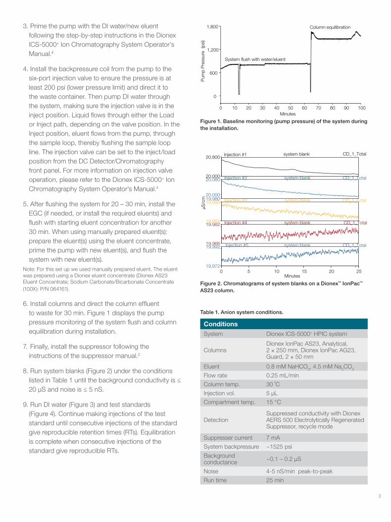
Figure 1. Baseline monitoring (pump pressure) of the system during the installation.
Table 1. Anion system conditions.
ConditionsSystem Dionex ICS-5000+ HPIC system
ColumnsDionex IonPac AS23, Analytical, 2 × 250 mm, Dionex IonPac AG23, Guard, 2 × 50 mm
Eluent 0.8 mM NaHCO3, 4.5 mM Na2CO3
Flow rate 0.25 mL/min
Column temp. 30 ˚C
Injection vol. 5 µL
Compartment temp. 15 °C
DetectionSuppressed conductivity with Dionex AERS 500 Electrolytically Regenerated Suppressor, recycle mode
Suppresser current 7 mA
System backpressure ~1525 psi
Background conductance ~0.1 – 0.2 µS
Noise 4-5 nS/min peak-to-peak
Run time 25 min
0 10 20 30 40 50 60 70 80 90 100
0
600
1,200
1,800
Minutes
Pum
p P
ress
ure
(psi
)
System �ush with water/eluent
Column equilibration
0 5 10 15 20 25 19.972
19.992 Injection #5 system blank CD_1_Total 19.966
19.982 Injection #4 system blank CD_1_Total 19.965
19.995 Injection #3 system blank CD_1_Total 19.980 20.000
20.080 Injection #2 system blank CD_1_Total 20.000
20.800 Injection #1 system blank CD_1_Total
S/c
m
Minutes
Figure 2. Chromatograms of system blanks on a Dionex™ IonPac™ AS23 column.
3. Prime the pump with the DI water/new eluent following the step-by-step instructions in the Dionex ICS-5000+ Ion Chromatography System Operator’s Manual.4
4. Install the backpressure coil from the pump to the six-port injection valve to ensure the pressure is at least 200 psi (lower pressure limit) and direct it to the waste container. Then pump DI water through the system, making sure the injection valve is in the inject position. Liquid flows through either the Load or Inject path, depending on the valve position. In the Inject position, eluent flows from the pump, through the sample loop, thereby flushing the sample loop line. The injection valve can be set to the inject/load position from the DC Detector/Chromatography front panel. For more information on injection valve operation, please refer to the Dionex ICS-5000+ Ion Chromatography System Operator’s Manual.4
5. After flushing the system for 20 – 30 min, install the EGC (if needed, or install the required eluents) and flush with starting eluent concentration for another 30 min. When using manually prepared eluent(s): prepare the eluent(s) using the eluent concentrate, prime the pump with new eluent(s), and flush the system with new eluent(s).
Note: For this set up we used manually prepared eluent. The eluent was prepared using a Dionex eluent concentrate (Dionex AS23 Eluent Concentrate; Sodium Carbonate/Bicarbonate Concentrate (100X): P/N 064161).
6. Install columns and direct the column effluent to waste for 30 min. Figure 1 displays the pump pressure monitoring of the system flush and column equilibration during installation.
7. Finally, install the suppressor following the instructions of the suppressor manual.2
8. Run system blanks (Figure 2) under the conditions listed in Table 1 until the background conductivity is ≤ 20 µS and noise is ≤ 5 nS.
9. Run DI water (Figure 3) and test standards (Figure 4). Continue making injections of the test standard until consecutive injections of the standard give reproducible retention times (RTs). Equilibration is complete when consecutive injections of the standard give reproducible RTs.

4
0 5 10 15 20 25 19.10 19.20
20.00 20.10
Minutes
µS/cm
Figure 3. Chromatogram of DI water blank on a Dionex IonPac AS23 column.
0 5 10 15 20 25 19
20
33
1
2
3
4 5
6 7
8
9
10
µS/cm
Minutes
Peaks (mg/L) Peaks (mg/L) 1. Fluoride 3 6. Chlorate 25 2. Chlorite 10 7. Bromide 25 3. Bromate 20 8. Nitrate 25 4. Chloride 6 9. Phosphate 40 5. Nitrite 15 10. Sulfate 30
Figure 4. Chromatogram of the QAR standard on a Dionex IonPac AS23 column.
Preparation of the anion system (prior to a switch to a cation system)Install and configure the Dionex AS-AP Autosampler and prepare the Dionex AERS 500 Anion Electrolytically Regenerated Suppressor as described under cation system for the Dionex CERS 500 suppressor. Flush the system with DI water. After flushing the system for 2 – 3 h, install the Dionex EGC Eluent Generator Cartridge (if needed). For information on installation and conditioning of the Dionex EGC III K2CO3 cartridge and Dionex EPM III, consult Thermo Scientific Application Note 10525 and the Eluent Generator Cartridges Product Manual (Document No. 065018-04).3
Install the Dionex IonPac AG23 and AS23 columns. Equilibrate the column with eluent for 30 min at 0.25 mL/min and run DI water and QAR test standards. The column will be equilibrated when three consecutive injections of this standard produce the same RTs for all analytes. Confirm that the resulting chromatogram resembles that in the column’s QAR. Note that the chromatogram shown in the QAR sheet is generated without a guard column; therefore, analyte RTs should be longer than those shown in the QAR.
Switching the system from anion to cation analysis1. Remove all the consumables from the anion set up
including the eluent generator cartridge, Dionex CR-ATC Continuously Regenerated Anion Trap Column, columns, and AERS Anion Electrolytically Regenerated Suppressor.
2. Before preparing new eluent, all eluent reservoirs should be emptied and rinsed thoroughly (inside and out) with filtered DI water.
3. Prime the pump with the DI water/eluent (when using manually prepared eluents), following the step-by-step instructions in the manual.4
4. Install the backpressure coil from the pump to the six-port injection valve to ensure the pressure is ≥ 200 psi and direct it to the waste container. Then, pump DI water through the system making sure the injection valve is in the inject position. In the Inject position, eluent flows from the pump, through the sample loop, thereby flushing the sample loop line. The injection valve can be set to the inject position from the DC Detector/Chromatography front panel. For more information on injection valve operation, please refer to the Dionex ICS-5000+ Ion Chromatography System Operator’s Manual.4
5. After flushing the system for 20 – 30 min, install the Dionex EGC Eluent Generator Cartridge (if needed) and flush with starting eluent concentration for another 30 min. Figure 5 shows the pump pressure monitoring for the system during the installation of the EGC.
6. Install columns and direct the column effluent to waste for 30 min, and then connect to the suppressor.
7. Monitor the baseline (Figure 6) under the method conditions listed in Table 2. Do not run samples until the background conductivity is ≤0.5 µS and noise is ≤1 nS.
Test the column performance under the conditions described in the column’s QAR. Figure 7 shows the chromatogram of the QAR standard. Continue making injections of the test standard until consecutive injections of the standard give reproducible RTs. Equilibration is complete when consecutive injections of the standard give reproducible RTs.

Find out more at www.thermofisher.com/IC
©2017 Thermo Fisher Scientific Inc. All rights reserved. All trademarks are the property of Thermo Fisher Scientific and its subsidiaries. This information is presented as an example of the capabilities of Thermo Fisher Scientific products. It is not intended to encourage use of these products in any manners that might infringe the intellectual property rights of others. Specifications, terms and pricing are subject to change. Not all products are available in all countries. Please consult your local sales representatives for details. TN72439-EN 0917S
ConditionsSystem Dionex ICS-5000+ HPIC system
ColumnsDionex IonPac CS16 Analytical, 3 × 250 mm, Dionex IonPac CG16 Guard, 3 × 50 mm
Eluent 30 mM KOH
Flow source Dionex EGC 500 MSA cartridge with high pressure CR-CTC
Flow rate 0.36 mL/min
Injection vol. 25 µL
Column temp. 40 °C
Compartment temp. 15 °C
Detection
Suppressed conductivity with Dionex CERS 500 Electrolytically Regenerated Suppressor, recycle mode
System current 32 mA
System backpressure ~2170 psi
Noise 0.2 – 0.4 nS/min peak-to-peak
Run time 25 min
0 10 20 30 40 50 55.6 0
500
2,500 P
ump
Pre
ssur
e (p
si)
Minutes
System �ush with water
After EGC III MSA installation
Figure 5. Baseline monitoring (pump pressure) for cation system.
0.00
0.50
1.00
1.60
µS/cm
2,160.0
2,250.0
Pum
p P
ress
ure
(psi
)
Minutes
0 10 20 30 40 50 60 70 80 90 102 Minutes
0 10 20 30 40 50 60 70 80 90 102
A
B
Figure 6. Baseline monitoring for cation system (A) chromatogram: conductivity monitoring; (B) chromatogram: pump pressure monitoring.
Peaks (mg/L) Peaks (mg/L) 1. Lithium 0.05 4. Potassium 0.50 2. Sodium 0.20 5. Magnesium 0.25 3. Ammonium 0.20 6. Calcium 0.50
0 5 10 15 20 25 0.0
0.2
1.1
1 2
3
4
5 6
µS/cm
Minutes
Figure 7. Chromatogram of the QAR standard on a Dionex IonPac CS16 column.
Table 2. Cation system conditions.
References1. Thermo Scientific AS-AP Autosampler Operator’s Manual
(Document No. 065361) https://tools.thermofisher.com/content/sfs/manuals/Man-065361-AS-AP-Autosampler-Man065361-EN.pdf
2. Thermo Scientific Dionex ERS 500 Suppressor Manual https://tools.thermofisher.com/content/sfs/manuals/Man-031956-IC-Dionex-ERS-Suppressor-Man031956-EN.pdf
3. Thermo Scientific Eluent Generator Cartridge Product Manual (Document No. 065018-05) http://tools.thermofisher.com/content/sfs/manuals/Man-065018-Eluent-Generator-Cartridge-MAN065018-EN.pdf
4. Thermo Scientific Dionex ICS-5000+ Ion Chromatography System Operator’s Manual (Document No. 065446) https://tools.thermofisher.com/content/sfs/manuals/Man-065446-IC-ICS-5000+-Operators-Manual.pdf