preliminary study on mechanism and...
TRANSCRIPT

PRELIMINARY STUDY ON MECHANISM AND IMPROVEMENT OF LOW-PRESSURE GROUTING IN LIQUEFIABLE GROUND M. Chang, C.C. Chen, T.W. Mao, W.R. Chiu, Dept. of Construction Engineering, NYUST, Taiwan, ROC H.S. Hsieh, Trinity Foundation Engineering Consultants, Taiwan, ROC P.J. Yang, Diffisoil Geotechnical Engineering Co., Taiwan, ROC ABSTRACT Being situated in the Circum-Pacific Seismic Zone, Taiwan has been suffering from frequent earthquakes that sometimes resulted in serious damages to engineering structures and foundations. A series of highly populated alluvial plains exist on the west portion of the island, and are vulnerable to liquefaction due to ground shaking. To improve the liquefaction resistance, several ground stabilization techniques were employed, in which low-pressure grouting has been the most widely adopted method in the island. The paper herein discusses local experiences in application of the technique. Although low-pressure grouting is frequently used, uncertainties remain in regard to the mechanism and the effectiveness of it. An in-situ grouting program with subsequent excavation was therefore conducted. The paper discusses the results of field observations as well as laboratory testing on the grouted soils. A numerical simulation of the grouting was also performed and discussed for verification of the observed mechanism. RÉSUMÉ Étant situé dans la zone séismique Circum-Pacifique, Taiwan avait souffert des tremblements de terre fréquents qui ont parfois eu comme conséquence des dommages sérieux aux structures et aux bases de technologie. Une série de plaines alluviales fortement peuplées existe sur la partie occidentale de l'île, et est vulnérable à la liquéfaction due à la secousse au sol. Pour améliorer la résistance de liquéfaction, plusieurs techniques au sol de stabilisation ont été utilisées, dans lesquelles le jointoiement à basse pression a été la méthode le plus largement adoptée en île. Le papier ci-dessus discute des expériences locales dans l'application de la technique. Bien que le jointoiement à basse pression soit fréquemment employé, les incertitudes demeurent en vue de le mécanisme et l'efficacité d'elle. Un programme de jointoiement in-situ avec l'excavation suivante a été donc conduit. Le papier discute les résultats des observations de champ aussi bien que l'essai en laboratoire sur les sols scellés au ciment. Une simulation numérique du jointoiement a été également effectuée et discutée pour la vérification du mécanisme observé. 1. INTRODUCTION Being situated in the conjunction area between Philippine oceanic plate and Eurasia continent, the topography of Taiwan is characterized by a series of mountains (i.e., Central Mountain Range) which covers about 2/3 of the central area (elongated from north to south) of the island. The Central Mountain Range, with elevations of 2000m to 4000m (above mean sea level), forms a significant descending grade (laterally) of up to 5-10% (towards the sea). Accordingly, the river systems on the island are mostly running westwards or eastwards, and have caused significant erosions in their upstream river beds and depositions in the downstream areas. In the west portion of the island, a series of alluvial deposits by some of the major river systems are widely extended and highly populated. Based on historic data provided by Central Weather Bureau (CWB) of Taiwan, numerous liquefaction incidents were recorded due to ground shaking and had resulted in significant casualties and damages on these alluvial deposits. On September 21, 1999, a sever earthquake (Chi-chi, MW=7.7, ML=7.3) hit the central part of Taiwan, with more than 2300 killed, 8700 wounded, and enormous buildings and structures damages (Ma et al. 1999). The earth-
quake was triggered by a thrust fault, with a rupture length of about 85Km (Tseng 1999). The duration of the main shaking was 40 seconds and extensive liquefaction phenomena were observed on the mid-west alluvial plains (NCREE 2000; Ueng et al. 2000). Figure 1 shows an example of liquefaction failure during the earthquake.
Figure 1. Failure of building foundation due to soil liquefaction in the 1999 Chi-chi earthquake, Taiwan.
Sea to Sky Geotechnique 2006
641
To mitigate the liquefaction problem, several engineering alternatives have been adopted, including ground stabili-zations and deep foundations. Although less precise in the effectiveness, ground stabilization techniques are generally preferred in Taiwan due to relatively low costs. While different ground stabilization measures are currently available, the grouting method appears to be most widely employed in the island. 2. GENERAL PRACTICE OF LOW-PRESSURE
GROUTING IN TAIWAN In local practice, the grouting method can be further divided into 3 subcategories: jet grouting (pressure >150 Kg/cm2), compaction grouting (pressure <60Kg/cm2), and low-pressure grouting (pressure <20Kg/cm2) (TCRI 1984; Hausmann 1990; Huang et al. 1994; Li 1997; Woo et al. 1999). Jet grouting is considered relatively more precise; however, its cost may be still high (Li 1997). Compaction grouting is primarily used for lifting and levelling the heavy structures by injection of stiff mortar grouts. Since it requires different setup of the equipment, the technique is not so prevailing in Taiwan (Rei 1992; Huang et al. 1994). Low-pressure grouting has been the most widely adopted technique for the treatment of liquefiable ground because of its relatively low cost and simple equipment setup. Main applications of the low-pressure grouting in the local practice are in the areas of ground strengthening (liquefaction resistance), leak prevention, and structure lifting (TCRI 1984; Woo et al. 1999). The grouting can be implemented through different types of injection pipe, including: drilling rod (single tube), double tube, and sleeve tube (tube a manchette), in which the sleeve tube injection method has been developed for stage grouting and is generally considered better in the grouting control. In the local practice, the range of injection pressure for low-pressure grouting is normally 3~5 times the effective overburden pressure (TCRI 1984; Woo et al. 1999). The injection mechanism of grout into the ground is generally considered as permeation, compaction, and hydro-fracturing (Mitchell 1981; Hausmann 1990; Hou & Bai 1991; Gallavresi 1992; Woo et al. 1999). Studies have indicated the development of hydro-fracturing would be affected by the in-situ stress condition and other factors as well (Bjerrum et al. 1972; Jaworski et al. 1981; Liao 1994; Yanagisawa & Panah 1994; Hocking 1996; Alfaro & Wong 2001; Murdoch & Slack 2002). It is apparent that the injection mechanism would, to a large extent, determine the effectiveness of the grouting. However, results of studies on the injection mechanism were generally not conclusive and the improvement of ground by the grouting could not be practically quantified. Accordingly, the aim of the current study is intended to have a clearer picture on the mechanism of grouting, through field observation and mapping, and subsequent laboratory testing and numerical simulations.
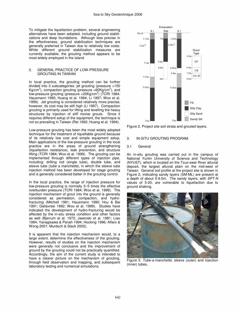
Figure 2. Project site soil strata and grouted layers. 3. IN-SITU GROUTING PROGRAM 3.1 General An in-situ grouting was carried out in the campus of National Yunlin University of Science and Technology (NYUST), which is located on the Tzuo-swei River alluvial deposit, the largest alluvial plain on the mid-west of Taiwan. General soil profile at the project site is shown in Figure 2, indicating sandy layers (SM-ML) are present at a depth of about 5-9.5m. The sandy layers, with SPT-N values of 5-20, are vulnerable to liquefaction due to ground shaking.
Figure 3. Tube-a-manchette, sleeve (outer) and injection (inner) tubes.
B-1 B-2
�
�
�
� � �
� � � �
� � � �
� � � �
1.15m
5.2m
7.55m
9.45m
15m
1m
4.9m
6.0m
8m
1.05m
6.05m
6.9m
9.45m
15m
2.0m
2.2m
GL=0
Excavation Site
4.0m
8.0m
6.0m
7.0m
Grout Type
GC
B
CB
SA-40
Fill Silty Clay Silty Sand Sandy Silt
Sea to Sky Geotechnique 2006
642

A low-pressure grouting was conducted though tube-a-manchette (Figure 3) in a grout hole (15-cm diameter) at a depth interval of 4-8m below the ground surface. As indicated in Figure 2, three grout types were injected at different depths: GCB (sodium silicate, cement, bento-nite, water), CB (cement, bentonite, water), and SA-40 (SA-40 solution, sodium silicate, water). GCB and CB grouts are of suspension type with gel times of 1min and 16 hrs, respectively. SA-40 was a solution grout and the gel time was set at about 3~5 min. The grouting proce-dure was controlled at a fix amount of grout volume per depth (i.e., 0.95 m3/m) into the ground. Depending on the grout type used and the soil material encountered, the injection pressure and the flow rate were varied in the ranges, 150-500 KPa and 5-10 l/min, respectively. 3.2 Ground Deformation Ground heaving was observed through a system of grid points on the ground surface and surveyed at the end of each grouting step. Figure 4 shows results of ground heaving (Z-exaggerated) of the SE quadrant area at the end of final grouting step. As can be seen, in a close vicinity of the grout hole (i.e., 1m radius) the ground heaved 20-25mm (5-6.5% of grout depth interval); while in a 3m radial distance, the ground heaved about 15mm. The ground heaving area would be expected to extent to a distance of 4-8m from the grout hole, which was about the same range as the grouting depth.
Figure 4. Ground surface heaving (Grouting Step 12C). Lateral deformation of the ground was monitored by two inclinometers (I-1 & I-2) located at horizontal distances of 1m and 2m, respectively, from the grout hole. Results of lateral deformation at I-1 are shown in Figure 5 at each of the grouting steps. In the GCB grouting stage (Depth: -4~-6m; Grouting Steps: 1~6), lateral deformations of the ground were apparent, showing the grouting tended to compress the ground laterally and in an upward sense. The maximum lateral deformation was found 19mm at about 3m below the ground surface. In the CB grouting stage (Depth: -6~-7m; Grouting Steps: 7~9), the results show lateral deformations were medium. In the SA-40 grouting stage (Depth: -7~-8m; Grouting Steps: 10~12), lateral deformations were relatively small, implying the grouting had caused more permeation in the ground.
Figure 5. Lateral ground deformations at Inclinometer I-1. 3.3 Observed Mechanism of Grouting The mechanism of grouting would be influenced by a number of factors, including soil type, in-situ stress state, grout type, injection pressure, flow rate, gel time, etc. In considering the details of the grouting program, soil type, grout type, and gel time were expected as the three factors that had major contributions to the observed mechanism of grouting at the site. Figure 6 shows an example of the observed hydraulic fractures and the permeation zones (in close vicinities along the fractures) at GL:-5.5m, indicating two clearly visible inclined hydro-fractures emanated from the grout hole. Figure 7 illustrates results of the field mapping on the floor and walls at GL:-7.5m of the excavated site. It was noticed that significant permeation had occurred around the grout hole and in the vicinities of the hydro-fractures.
Figure 6. Observed hydraulic fractures and permeation zones in ground (GL:-5.5m).
0 4b 7b 10b 12c
0
-1
-2
-3
-4
-5
-6
-7
-8
-9
Grouting Step
Dep
th (m
)
16.00 -20.00
12.00 -16.00
8.00 -12.00
4.00 -8.00
0.00 -4.00
LateralDeformationof I-1 (mm)
GCB
CB
SA-40
Grout Hole
Grout
Inclinometer, I-
W
Sea to Sky Geotechnique 2006
643

Results of the observed mechanism at different depth intervals are summarized in Table 1. It was found that hydro-fracturing tends to be more pronounce for the injection of suspension grout with short gel time (e.g., GCB grout) in all soils. For injection of the suspension grout with long gel time (e.g., CB grout) or the solution grout (e.g., SA-40), the permeation would be obvious in the sandy layer. It was also noted that the more fine-grained (cohesive) the soil is, the more hydro-fracturing mechanism would be observed. Table 1. Observed mechanism of grouting.
Observed mechanism
Depth (m) Soil type
Grout type
Gel time
P* C* F* -4 ~ -5 CL GCB 1 min ● ●● -5 ~ -6 SM (FC<25%) GCB 1 min ● ●● -6 ~-7 SM-ML (FC>30%) CB 16 hrs ●● ● ● -7 ~-8 SM-ML (FC>30%) SA-40 ~4 min ●● ●
* P = permeation; C = compaction; F = hydro-fracturing
4. LABORATORY EVALUATION OF LIQUEFACTION
RESISTANCE OF GROUTED SANDS The grouted samples at various distances from the grout hole were collected on-site during the stage exaction after grouting. A laboratory testing program was subsequently conducted to evaluate the improvement in static/cyclic strengths of the grouted soils. Figures 8 and 9 show results of the cyclic triaxial testing of the grouted and original sands at GL:-5.5m. The liquefaction resistance was determined by the cyclic resistance ratio (CRR; σ’dp/2σ’c) required to cause initial liquefaction in a certain number of stress cycles equivalent to a given magnitude of an earthquake (Youd et al. 2001). Results indicate a general increase in the liquefaction resistance (10-50%
increase for M=7.5 EQs; 50-80% increase for M=6 EQs) for the grouted sand located within a 2m distance from the grout hole. For the grouted sand located further away from the grout hole, the improvement in liquefac-tion resistance appears to be insignificant.
Figure 8. Results of cyclic triaxial testing on grouted sands at GL:-5.5m.
Figure 9. Improvements of liquefaction resistance (CRR) of grouted sands at GL:-5.5m.
G
1m
3m
2m
1m
3m
2m
East direction
(m)
S
o
u
th
d
ire
c
tio
n
(m
)
� � �
� � �
-0.5m
-6.5m
CB
G
ro
ut
-8m
SA
-4
0 G
rou
t
Silty sand(FC<25%)Silty clayLegend Silty sand(FC>30%)
Grout Hole
Inclinometers
Figure 7. Mapping of hydro-fractures and permeation zones at GL:-7.5m.
0
0.05
0.1
0.15
0.2
0.25
0.3
0.35
0.4
0.45
1 10 100 1000� � � �� N
��������σ
' dp/2σ
' c
� � 5.5m� � � 0.5m� � 5.5m� � � 1.5m� � 5.5m� � � 2.5m� � 5.5m� � � 4.0m� � 5.5m� � �
GL:-5.5m SM (FC<25%)
Liquefaction Cycle Number, Nl
0.5m to grout hole center 1.5m to grout hole center 2.5m to grout hole center 4.0m to grout hole center Original un-grouted sands C
yclic
Str
ess
Rat
io,
Original Sand
0
0.2
0.4
0.6
0.8
1.0
0 1 2 3 4 5 6
� � � � � � � �
CR
R
Neq
=26,M=8.5
Neq
=5.5,M=6.0
N
eq
=15,M=7.5
� � � (Neq
=26,M=8.5)
� � � (Neq
=5.5,M=6.0)
� � � (Neq
=15,M=7.5)
Distance from Grout Hole (m)
CR
R
Original (Neq=5.5, M=6.0)
Original (Neq=15, M=7.5)
Original (Neq=26, M=8.5)
Grouted:
Sea to Sky Geotechnique 2006
644

5. NUMERICAL SIMULATION OF GROUTING 5.1 General The purpose of numerical simulation for the current study was in two folds: (1) to ensure the response of numerical analysis would generally comply with the observations of grouting in the field; (2) to gain more insights on the development of grouting mechanism. A numerical code, PFC2D (Itasca 1999), was therefore employed. The two-dimensional distinct element code is capable of describ-ing the movement of particles in a particle assembly under the influence of external (e.g., grout fluid) forces and inter-particle forces. General procedures for the analysis include computation of the total force on each particle in a particle assembly. The force causes movement of each particle and the rearrangement of the particle assembly. In accordance, pore fluid pressures as well as particle contact (normal & shear) forces are recalculated for the new total force on each particle of the assembly. The process continues for a number of time steps defined by the user or until certain equilibrium criterion has been reached. The code employs two contact constitutive models (linear & non-linear) for evaluation of the normal and shear forces at particle contacts. The fluid flow satisfies Darcy’s law. The flow occurs due to a pressure difference between two adjacent pores, which subsequently causes changes in the pore volumes and the fluid pressures as well. For a fully coupled problem, fluid pressure gives rise to an extra force on the particles, which in turn affects the movement of the particles. The movement of particles also causes deformation of the particle assembly and a change in the pore volume, which in turn affects the fluid pressure as well as the particle movement. Fully coupled flow calculations would be very time consuming and was only considered for the borehole (i.e., grout hole) pore space in the current study. For the rest of pore spaces, the subsequent change in the pore volume was assumed to have no further effect on the changes in fluid pressure (i.e., one-way coupled flow). The adopted parameters for the numerical simulations are indicated in Table 2. A total of 9779 particles had been randomly generated within a 1m×1m area and were Table 2. Adopted parameters for numerical simulation.
Parameter Value Particle cohesion, c (Pa) 1E+6 Particle friction coefficient, fric 0.6 Contact normal stiffness, kn (N/m) 1E+9 Contact shear stiffness, ks (N/m) 1E+9 Initial porosity, ni 0.15 Initial particle sizes, rmax / rmin (m/m) 0.005 / 0.004 Particle contact bond (Pa) 1E+6 Permeability, κ (m/s) 1E-5 Fluid bulk modulus, K (Pa) 1E+9 Flow time step, dt (s) 0.01 Injection pressure, P (Pa) 1E+8
subjected to an isotropic confining pressure (σx=σy) of 100KPa. The pore spaces were initially assumed to be dry prior to the grouting. In order to maintain the bore-hole wall from collapsing for the subsequent grouting, an
Figure 10. Development of hydro-fractures around bore-hole due to grouting.
4000 + 300 Time Steps
4000 + 500 Time Steps
4000 + 100 Time Steps
4000 + 000 Time Steps
Sea to Sky Geotechnique 2006
645
initial value of 1.5 times the average confining pressure was applied. Water, with a viscosity of unity, was used as the grout fluid in the analysis. All of the simulations were made by a controlled (constant) injection pressure. 5.2 Development of Grouting Mechanism The numerical model with the assumed parameters had been tested on its suitability for the study of the grouting mechanism. The results were acceptable and the per-formance of the model was generally in accord with the observations in the field. Since calibration of the numerical model for the site-specific materials has not been conducted, the results as follows provide pictures that soil materials would likely behave in the grouting. Figure 10 shows the responses of a borehole (i.e., grout hole) and it’s surrounding particles at different compu-tation times when a constant fluid pressure (represented by the blue dot in the borehole) is applied in the hole. Prior to the fluid injection, 4000 time steps were required for the particle assembly with the excavated borehole to reach a stable and equalized condition. The dashed circle depicts the original shape of the borehole. During the injection process, the borehole was enlarged and the particles behind borehole wall became squeezed with the time. Some particles on the boundary of the borehole were lost in contact due to tension (indicated by “short black lines”) or shearing (indicated by “short red
lines”). It was noted that most of the deleted contacts were by tension and apparently occurred earlier than the emerging of a hydro-fracture. Hydro-fractures would normally take place in the area with most intense deleted contacts. It’s also interesting to know that the fluid (i.e., grout) permeate through the borehole into the particles behind, as shown in the blue dots for the fluid pressure penetrations. The fluid permeation was apparently affected by the hydraulic conductivity assumed for the particle assembly and other factors as well. The influence of hydraulic conductivity will be examined in the following. In this example, hydro-fractures were found to occur at the time steps of about 4300~4500, by which time the borehole had experienced significant enlarge-ment and tension around the borehole boundary.
Figure 11. Radial compression around borehole due to grouting.
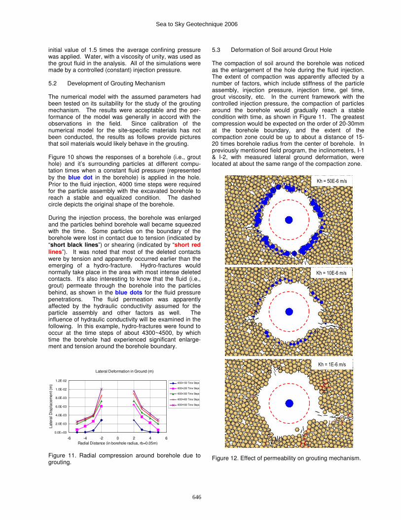
5.3 Deformation of Soil around Grout Hole The compaction of soil around the borehole was noticed as the enlargement of the hole during the fluid injection. The extent of compaction was apparently affected by a number of factors, which include stiffness of the particle assembly, injection pressure, injection time, gel time, grout viscosity, etc. In the current framework with the controlled injection pressure, the compaction of particles around the borehole would gradually reach a stable condition with time, as shown in Figure 11. The greatest compression would be expected on the order of 20-30mm at the borehole boundary, and the extent of the compaction zone could be up to about a distance of 15-20 times borehole radius from the center of borehole. In previously mentioned field program, the inclinometers, I-1 & I-2, with measured lateral ground deformation, were located at about the same range of the compaction zone.
Figure 12. Effect of permeability on grouting mechanism.
Lateral Deformation in Ground (m)
0.0E+00
2.0E-03
4.0E-03
6.0E-03
8.0E-03
1.0E-02
1.2E-02
-6 -4 -2 0 2 4 6Radial Distance (in borehole radius, rb=0.05m)
Late
ral D
ispl
acem
ent (
m) 4000+100 Time Steps
4000+200 Time Steps
4000+300 Time Steps
4000+400 Time Steps
4000+500 Time Steps
Kh = 50E-6 m/s
Kh = 1E-6 m/s
Kh = 10E-6 m/s
Sea to Sky Geotechnique 2006
646

5.4 Effect of Permeability on Grouting Mechanism The effect of soil type (e.g., sand vs. clay) on grouting mechanism was of interest. Since sand and clay differ in the characteristics of grain size, cohesion, friction angle, permeability, etc, the entire effect by soil type needs to account for all of different characteristics of the two soils. As a preliminary investigation, the permeability (hydraulic conductivity) was considered as the major characteristic for sand and clay. The results of permeability effect on the grouting mechanism are shown in Figure 12. With the same injection pressure and at the same time step, the mechanism of grouting for the soils with various permeabilities (50E-6, 10E-6, 1E-6 m/s) was apparently different. For soil with relatively high permeability, the permeation mechanism of grouting (indicated by the blue
dots for the fluid pressure penetration) was obvious. For the soil with relatively low permeability, the hydro-fracturing mechanism of grouting became dominant. 6. CONCLUDING REMARKS The paper herein discusses injection mechanism and performance of low-pressure grouting, through in-situ mapping, laboratory testing, and numerical simulations. The major findings of the current study are summarized as follows: � A surface heaving of 5-6.5% of the grouting depth
interval would be expected at the grouting point, for the grouting depth of 4-8m below the ground surface. The area of surface heaving would extend to a horizontal distance (from the grout hole) in about the same range of the grouting depth;
� For suspension grouts (e.g., GCB grout), the lateral
ground deformation due to grouting would be apparent. The ground would deform laterally and in an upward sense for the grouting in a shallow depth (e.g., 4-6m below ground surface). For solution grout (e.g., SA-40 grout), lateral ground deformations were less obvious. Numerical simulations indicated lateral compression would extend to a distance of 15-20 times the borehole radius from the center of the borehole;
� Hydro-fracturing tends to be more pronounce for the
injection of suspension grout with short gel time (e.g., GCB grout; 1min) in all soils. For injection of the suspension grout with long gel time (e.g., CB grout; 16hrs) or the solution grout (e.g., SA-40; 4min), the permeation would be obvious in the sandy layer;
� The more fine-grained (or cohesive) the soil is, the
more hydro-fracturing mechanism would be expected. The more coarse-grained (or cohesionless) the soil is, the more permeation mechanism would be observed. Results of numerical simulations on soil permeability confirmed the field observations;
� Numerical simulation on the development of grouting
mechanism indicated the borehole enlarged in about
the same time the fluid pressure had applied. Some particles around the borehole were observed lost in their contacts in the early stage of injection. Hydro-fractures would finally take place in the areas with most intense deleted contacts; and
� Results of laboratory testing indicated a general
increase in the liquefaction resistance of the grouted sand located within a 2m distance from the grout hole. The liquefaction resistance would increase about 10-50% for M=7.5 or higher earthquakes, and 50-80% for M=6 earthquakes.
7. ACKNOWLEDGEMENTS The writers would like to acknowledge the contributions of the geotechnical group at NYUST on the field grouting and laboratory testing program for this study. References Alfaro, M., and Wong, R.C.K. 2001. Laboratory studies on
fracturing of low-permeability soils, Canadian Geotechnical Journal 38: pp. 303-315.
Bjerrum, L., Nash, J.K.T.L., Kennard, R.M., and Gibson, R.E. 1972. Hydraulic fracturing in field permeability testing, Geotechnique, 22(2): pp. 319-332.
Gallavresi, F. 1992. Grouting improvement of foundation soils, Proceedings of the Conference on Grouting, Soil Improvement and Geosynthetics, New Orleans, Louisiana, GSP No.30, ASCE, I: pp. 1-38.
Hausmann, M.R. 1990. Engineering Principles of Ground Modification, McGraw Hill.
Hocking, G. 1996. Soil hydraulic fracturing, Water Well Journal 50(5): pp. 70-72.
Hou, X.Y., and Bai, Y. 1991. The mechanism and appli-cation of grouting in soft clay, Proceedings of the 9
th
Asian Regional Conference on SMFE, Thailand, pp. 487-490.
Huang, N.H., Kao, H.S., Kuo, K.J., and Chang, C.L. 1994. Effect of compaction grouting on sand-gravel layer, Sino Geotechnics 47: pp. 23-33.
Itasca. 1999. PFC2D Manuals. Jaworski, G.W., Duncan, J.M., and Seed, H.B. 1981.
Laboratory study of hydraulic fracturing, Journal of Geotechnical Engineering, ASCE, 107(6):pp.713-733.
Li, C.L. 1997. Application and construction technique of jet grouting, Sino Engineering 55: pp.53-74.
Liao, H.C. 1994. Application of soil grouting on pipe curtain projects, Sino Geotechnics 47: pp. 35-54.
Ma, K.F., Lee, C.T., Tsai, Y.B., Wang, C.Y., and Wen, K.L. 1999. The 1999 Chi-chi Taiwan earthquake, Proceedings of Investigation on Damages of the 1999 Chi-Chi Earthquake, Taiwan, II: pp. 1-15.
Mitchell, J.K. 1981. Soil improvement: state-of-the-art, Proceedings of the 8
th International Conference on
SMFE, Stockholm, Sweden, pp. 1-57. Murdoch, L.C., and Slack, W.W. 2002. Forms of hydraulic
fractures in shallow fine-grained formations, Journal of Geotechnical and Geoenvironmental Engineering, ASCE, 128(6): pp. 479-487.
Sea to Sky Geotechnique 2006
647

National Center for Research on Earthquake Engineering (NCREE), Taiwan. 2000. Investigation Report on Geotechnical Damages during the 921 Chi-Chi Earthquake.
Rei, C.H. 1992. Introduction of compaction grouting, Construction Information 123: pp. 33-42.
Taiwan Construction Research Institute (TCRI). 1984. Ground Improvement Techniques – Design Conside-rations of Chemical Grouting Method.
Tseng, C.L. 1999. The surface variations caused by the 921 Chi-chi earthquake, Proceedings of Investigation on Damages of the 1999 Chi-Chi Earthquake, Taiwan, IV: pp. 1-22.
Ueng, T.S., Chu, B.L., and Lin, P.S. 2000. Soil lique-faction characteristics in Yuanlin, Wufeng, and Nantou during Chi-chi earthquake, Sino Geotechnics 81: pp. 47-56.
Woo, S.M., Wang, K.J., and Lu, Y.C. 1999. Application of low pressure grouting on ground subsidence control - a case study. Proceedings of the 8
th Conference on
Current Researches in Geotechnical Engineering, Kentin, Taiwan, 1793-1807.
Yanagisawa, E., and Panah, A.K. 1994. Two dimensional study of hydraulic fracturing criteria in cohesive soils, Soils and Foundations, JSSMFE 34(1): pp. 1-9.
Youd, T.L., et al. 2001. Liquefaction resistance of soils: summary report from the 1996 NCEER and 1998 NCEER/NSF Workshops on evaluation of liquefaction resistance of soils, Journal of Geotechnical and Geoenvironmental Engineering, ASCE, 127(10): pp. 817–833.
Sea to Sky Geotechnique 2006
648