procesne kominikacije i softveri
TRANSCRIPT

8/3/2019 Procesne Kominikacije i Softveri
http://slidepdf.com/reader/full/procesne-kominikacije-i-softveri 1/18Siemens FI 01 · 2011
Communication
9/2 HART protocol
9/3 WirelessHART
9/6 PROFIBUS
9/7 FOUNDATION Fieldbus
WirelessHART Communincation
9/8 Communication blocks
9/9 SITRANS MDS -
Maintenance Diagnostic Station
Software
9/11 SIMATIC PDM -
Process Device Manager
Communication and Software
© Siemens AG 2010

8/3/2019 Procesne Kominikacije i Softveri
http://slidepdf.com/reader/full/procesne-kominikacije-i-softveri 2/18
Communication and SoftwareCommunication
HART protocol
9/2 Siemens FI 01 · 2011
■Overview
HART is a widely used communication standard for fielddevices. Specification of HART devices takes place through theHCF (HART Communication Foundation).
The HART standard expands the analog 4 to 20 mA signal for
modulated, industry-proven, digital signal transmission.
■Benefits
• Service-proven analog measured value transmission
• Simultaneous digital communication with bidirectional datatransmission
• Possibility of transmitting several measured variables fromone field device (e.g. diagnosis, maintenance and processdata)
• Connection to higher-level systems such as PROFIBUS DP
• Easy installation and startup
Use in conjunction with SIMATIC PDM
• Cross-vendor operation of all HART devices by means of stan-
dardized parameter records• HART field devices that are described by HART DD are inte-
grated in SIMATIC PDM through the HCF catalog. HART DD(Device Description) is standardized in SIMATIC PDM, multi-vendor and very widely used. Other HART field devices are in-tegrated in SIMATIC PDM through EDD (Electronic Device De-scription)
• Easy operation and startup of field devices, also inhard-to-reach locations
• Expanded diagnosis, evaluation and logging functions
■Application
These devices can be connected in different ways:
• Using the distributed I/O system
- SIMATIC ET 200M with the HART modules- SIMATIC ET 200iSP with the HART modulesor with analog modules 4 to 20 mA and a HART handheldcommunicator
• Using a HART modem, with which a point-to-point connectionis established between the PC or engineering station and theHART device
• Using HART multiplexers, which are contained in the HARTserver of the HCF
■ Integration
Siemens field devices for process automation which are listed inthis catalog and can be controlled using HART:
■Selection and Ordering data Order No.
D) Subject to export regulations AL:N, ECCN: EAR99H
Measuring instruments for pressure
SITRANS P DS III
SITRANS P P300
Measuring instruments for temperature
SITRANS TF
SITRANS TH300
SITRANS TR300
SITRANS TW
Flowmeters
SITRANS F M MAG 5000 HART
SITRANS F M MAG 6000 19“ / IP67 / I / I Ex d
SITRANS F M Transmag 2
SITRANS F C MASS 6000 19“ / IP67 / Ex d
SITRANS FUS060
Measuring instruments for level
Pointek CLS 500
SITRANS Probe LR
SITRANS Probe LU
SITRANS LR200
SITRANS LR250
SITRANS LR260
SITRANS LR300
SITRANS LR400
SITRANS LR460
SITRANS LC 500Positioners
SIPART PS2
SITRANS VP300
Power supply units and isolation amplifiers
SITRANS I
HART modem
• With RS 232 connection }
D)7MF4997-1DA
• With USB connection }
D)
7MF4997-1DB
} Available ex stock
© Siemens AG 2010

8/3/2019 Procesne Kominikacije i Softveri
http://slidepdf.com/reader/full/procesne-kominikacije-i-softveri 3/18
Communication and SoftwareCommunication
WirelessHART
9/3Siemens FI 01 · 2011
■Overview
WirelessHART is the first international industry standard for wire-less communication at field level in the area of process automa-tion. Hence this is the first time users are provided with a stan-dard for wireless communication at field level which ensures the
interoperability of instruments and components from differentmanufacturers.
■Benefits
WirelessHART enables access to the following:
• Measuring and control values
• Parameters
of field devices with HART interface. These usually include pres-sure, temperature, level or flow transmitters or actuators.
WirelessHART allows for the following:
• wireless transmission of measured values and their status
• wireless parameterization and diagnosis of field devices
The WirelessHART adapter can be used to enable field devices
with HART interfaces (that are designed for wired communica-tion) for wireless communication. This allows users to continueusing their proven devices while benefiting from and participatein addition in advantages offered by wireless communication.
■Application
Looking at the large number of possible applications and config-urations, we generally differentiate between two applicationtypes.
Background for the first type is the fact that according to esti-mates forwarded by the HART Communication Foundation(HCF), approximately 85 % of the over 30 million HART devicesin operation are used in an environment where only the 4 to20 mA interface rather than the HART interface of the device isused on a system level. Generally, data on the device can onlybe read on site. This is of particular disadvantage with devicesthat contain self-diagnostic functions - that’s what we call"stranded diagnosis".
In these cases, a WirelessHART adapter can offer assistance.Connected to the 4 to 20 mA loop, it allows central access to thedevice based on wireless communication. It does not affect pro-cess control systems which continue to receive the measuredvalue using the 4 to 20 mA loop.
Central access is enabled through a diagnostic station withSIMATIC PDM and SITRANS MDS software.
Main advantages:
• Increases the availability of the plant
• Increases plant transparency
• Reduces costs due to employing a predictive rather than pre-ventative maintenance concept
• Reduces travel time in larger systems based on central ac-cess to field instrumentation
In the second application the 4 to 20 mA loop is omitted, all data in-cluding measured process values and diagnostic information aretransmitted wirelessly to a process control system, for example.
Main advantages are:
• No planning and installation of data cables, resulting in signif-icant cost reductions
• Higher system transparency due to additional and hitherto un-feasible installation of measuring points
• Process optimization due to flexible, temporary and cost-ef-fective measuring points via wireless communication
• Utilization of proven devices by using adapters
• The WirelessHART meshed network also makes it possible tobridge longer distances
■Design
This section introduces the application types described in theprevious section in greater detail.
The figure below shows a typical situation for the first applicationtype.
The adapter is connected to the 4 to 20 mA loop, which is usedto transmit the measured value to the control system, or transmitthe setpoint to an actuator. The existing control system is not af-fected by the WirelessHART adapter.
The data, in particular diagnostic data from the devices is trans-mitted to the IE/WSN-PA LINK via the connected adapter and theWirelessHART network. The link provides this data to a diagnos-tic and maintenance station with installed SITRANS MDS soft-ware and SIMATIC PDM via an industrial Ethernet. Industrialwireless LAN can be used to save on the installation costs re-quired for Ethernet wiring. An extensive product portfolio ofScalance W components is available for this purpose.
The functionality of related to the SITRANS MDS is described ingreat detail on page 9/9 of this catalog.
Controller without
HART support
Remote I/O station
w/o HART support
SITRANS
MDSOS
IE/WSN-
PA LINK
SITRANS
AW200
Industrial
Ethernet
Industrial Ethernet
P R O F I B U S
Wireless
HART
IWLAN
IEEE802.11
4–20 mA
4–20 mA
4–20 mA
© Siemens AG 2010
8/3/2019 Procesne Kominikacije i Softveri
http://slidepdf.com/reader/full/procesne-kominikacije-i-softveri 4/18
Communication and SoftwareCommunication
WirelessHART
9/4 Siemens FI 01 · 2011
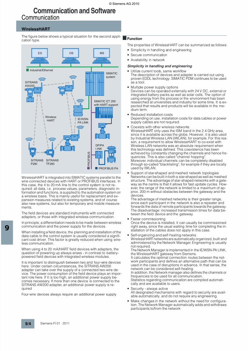
The figure below shows a typical situation for the second appli-cation type.
WirelessHART is integrated into SIMATIC systems parallel to thewire-connected devices with HART or PROFIBUS interfaces. In
this case, the 4 to 20 mA line to the control system is not re-quired: all data, i.e. process values, parameters, diagnostic in-formation and functions, is supplied to the automation system ona wireless basis. This is mainly useful for replacement and ex-pansion measures related to existing systems, and of coursealso new systems, but also for temporary and mobile measure-ments.
The field devices are standard instruments with connectedadapters, or those with integrated wireless communication.
In principle, a differentiation needs to be made between wirelesscommunication and the power supply for the devices.
When installing a field device, the planning and installation of thedata cable to the control system is usually considered a signifi-cant cost driver. This factor is greatly reduced when using wire-less communication.
When using 4 to 20 mA/HART field devices with adapters, thequestion of powering up always arises - in contrast to battery-powered field devices with integrated wireless modules.
It is important to distinguish between two and four-wire deviceshere. Under certain circumstances, the SITRANS AW200adapter can take over the supply of a connected two-wire de-vice. The power consumption of the field device plays an impor-tant role here. If it is too high, an additional power supply be-comes necessary. If more than one device is connected to theSITRANS AW200 adapter, an additional power supply is re-quired.
Four-wire devices always require an additional power supply.
■ Function
The properties of WirelessHART can be summarized as follows:
• Simplicity in handling and engineering
• Secure communication
• Availability in networkSimplicity in handling and engineering
• Utilize current tools, same workflowThe description of devices and adapter is carried out usingproven EDDL technology. SIMATIC PDM continues to be usedas a tool.
• Multiple power supply optionsDevices can be operated externally with 24 V DC, external orintegrated battery packs as well as solar cells. The option ofusing energy from the process or the environment has beenresearched at universities and industry for some time. It is ex-pected that results and products will be available in the me-dium term.
• Reduced installation costsDepending on use, installation costs for data cables or power
supply cables are not required.• Coexists with other wireless networks
WirelessHART only uses the ISM band in the 2.4 GHz area,since it is available across the globe. However, it is also usedby Industrial Wireless LAN (IWLAN), for example. For this rea-son, a requirement to allow WirelessHART to co-exist withWireless LAN networks was an absolute requirement whenthis technology was defined. This coexistence has beenachieved by constantly changing the channels and hence fre-quencies. This is also called "channel hopping".Moreover, individual channels can be completely disabledthrough so-called "blacklisting", for example if they are locallyused by IWLAN.
• Support of star-shaped and meshed network topologiesNetworks can be built in both a star-shaped as well as meshedstructure. The advantage of star-shaped networks with a gate-
way as the centre is that it allows for fast update cycles. How-ever, the range of the network is limited to a maximum of ap-prox. 200 m without obstacles between the gateway and thedevices.The advantage of meshed networks is their greater range,since each participant in the network is also a repeater andforwards the data of remote participants towards the gateway.The disadvantage: increased transmission times for data be-tween the field device and the gateway.
• Faster commissioningOnce the device is installed, it can usually be commissionedright away, since the usual waiting time for completing the in-stallation of the cables does not apply in this case.
• Self-organizing and self-healing networksWirelessHART networks are automatically organized, built andadministered by the Network Manager. Engineering is usually
not required.The Network Manager is implemented in the IE/WSN-PA LINK,the WirelessHART gateway from Siemens.It calculates the optimal connection routes between the net-work participants and defines an alternative path that can beused in the case of disruptions in advance. In that sense, thenetwork can be considered self-healing.In addition, the Network manager also defines the channels orfrequencies to be used for all communication.Statistics regarding communication are compiled automati-cally and are available to users.
• Security - always activeAll designated mechanisms with regard to security are avail-able automatically, and do not require any engineering.
• Make changes in the network without the need for configura-tion. The Network Manager automatically adds and withdraws
participants to/from the network.
SIMATIC
system
SIMATIC ET 200
with HART support
ES OS MS
IE/WSN-
PA LINK
SITRANS
AW200
SITRANS
TF280
SITRANS
P280
DP/PA
LINK
Industrial Ethernet
P R O F I B U S
Wireless
HART
PROFIBUS PA
© Siemens AG 2010

8/3/2019 Procesne Kominikacije i Softveri
http://slidepdf.com/reader/full/procesne-kominikacije-i-softveri 5/18
Communication and SoftwareCommunication
WirelessHART
9/5Siemens FI 01 · 2011
Secure communication
• Encryption - All information is automatically encrypted with128 bit AES prior to transmission
• Specific keys for each data packet
• Data integrity - Each data packet is checked for changes ordamage during transport.
• Device authenticationEach device must know the network identification number aswell as the join key. Otherwise the Network Manager does notinclude it in the network.
• Channel HoppingThe channel which is used will be changed according to theNetwork manager’s specifications after each telegram. Thisprovides an added level of security against spying activities.
• Failed authentification reportEach unsuccessful attempt by a participant to join the networkwill be recorded and made available to the user.
Availability in network
• Communication based on IEEE 802.15.4-2006Wireless communication takes place on the basis of a provenindustry standard. It allows for very minimal power consump-tion.
• Utilization of ISM band (2.4 GHz)
This band can be used worldwide without incurring additionalcosts.
• Channel hopping overcomes disruptionsDisruptions are usually limited to a small frequency range.By constantly changing the channel, i t is possible to overcomethe effects of such disruptions and hence increase the net-work’s reliability.
• Channel Black Listing permanently blocks disrupted chan-nels.When operating another network at the same location, thechannels occupied by that network can be blocked in theWirelessHART network.
• Self-healing networkThis aspect has already been discussed
• Redundant communication paths
The Network manager automatically calculates redundantcommunication paths. This significantly increases the level ofavailability.
Software Overview
Applications 1 and 2 will require the following software products
1) You can also contact your Siemens contact person.2) Other versions and accessories can be found in the product descriptions of this catalog.
■More information
More detailed information on the required WirelessHART soft-ware and hardware components can be found in theFI 01 catalog or at www.siemens.com/wirelesshart.
Component Products Order No.
A p p l i c a t i o n
t y p e 1
Maintenance Diagnostic Station SITRANS MDS 1)
SIMATIC PDM and Options
SIMATIC PDM Basic (4 Tags) 6ES7 658-3AX06-0YA5
Extend Basic to 128 Tags 6ES7 658-3XA06-2YB5
Extend Basic to up to 512 Tags 6ES7 658-3XB06-2YB5
Extend Basic to up to 1,024 Tags 6ES7 658-3XC06-2YB5
Extend Basic to up to 2,048 Tags 6ES7 658-3XD06-2YB5
SIMATIC PDM service (128 Tags) 6ES7 658-3JX06-0YA5
SIMATIC PDM Option HART Mux 6ES7 658-3EX06-0YB5
HART OPC Server V3.0 Included in SIMATIC PDM1)
WirelessHART gateway IE/WSN-PA LINK with integrated non-removable antenna 6GK1 411-6CA40-0AA0
WirelessHART adapter SITRANS AW2002) 7MP3112-1AA00-0AA0
A p p l i c a t i o n
t y p e 2
Process control system SIMATIC PCS 7
SIMATIC S7/SIMATIC PCS 7 function blocks for communicating withWirelessHART devices using the IE/WSN-PA LINK
9AE4110-3AA00
WirelessHART gateway IE/WSN-PA LINK with integrated non-removable aerial2) 6GK1 411-6CA40-0AA0
Field devices SITRANS AW2002) 7MP3112-1AA00-0AA0
SITRANS P2802) 7MP1120-...
SITRANS TF2802) MP1110-...
© Siemens AG 2010

8/3/2019 Procesne Kominikacije i Softveri
http://slidepdf.com/reader/full/procesne-kominikacije-i-softveri 6/18
Communication and SoftwareCommunication
PROFIBUS
9/6 Siemens FI 01 · 2011
■Overview
Today, distributed automation solutions based on open fieldbuses are state-of-the-art in large areas of the manufacturingindustry and process engineering. It is only with field buses thatthe functional benefits of digital communication can be put to full
use, e.g. better resolution of measured values, diagnosis optionsand remote parameterization.
PROFIBUS is today’s most successful open field bus with a largeinstalled base for a wide range of application. Standardization toIEC 61158 / EN 50170 provides you with future protection foryour investment.
■Benefits
• A uniform modular system from the sensor into the controllevel enables new plant concepts
• Problem-free exchangeability of field devices, including fromdifferent manufacturers, that comply with the standard profile
• Networking of transmitters, valves, actuators etc.
• Implementation of intrinsically safe applications through use of
the field bus in hazardous areas• Easy installation of 2-wire lines for joint energy supply anddata transmission
• Reduced cabling costs through savings of material and instal-lation time
• Reduced configuration costs through central, simpleengineering of the field devices (PROFIBUS PA and HART withSIMATIC PDM, also cross-vendor)
• Fast and error-free installation
• Lower service costs thanks to simpler wiring and plant struc-ture plus extensive diagnosis options
• Greatly reduced commissioning costs through simplified loopcheck
• Scaling/digitizing of the measured values in the field devicealready, hence no rescaling necessary in SIMATIC PCS 7
■Application
PROFIBUS is suitable for fast communication with distributedI/Os (PROFIBUS DP) in production automation as well as forcommunication tasks in process automation (PROFIBUS PA).It is the first field bus system that meets the demands of bothareas with identical communication services.
The transmission technique of the PROFIBUS PA is tailored tothe needs of the process industry. Interoperability between fielddevices from different manufacturers and remote parameteriza-tion of the field devices during operation are guaranteed by thestandardized communication services.
Using SIMATIC PDM (Process Device Manager), a uniform andcross-vendor tool for configuring, parameterizing, commission-
ing and diagnosis of intelligent process devices on thePROFIBUS, it is possible to configure a wide variety of processdevices from different manufacturers using one uniform graphi-cal user interface.
PROFIBUS PA can just as readily used in standard environmentsas well as hazardous areas. For use in hazardous areas,PROFIBUS PA and all connected devices have to be designedwith type of explosion protection Ex [i].
The uniform protocol of PROFIBUS DP and PROFIBUS PAenables the two networks to be interlinked, thus combining time-based performance with intrinsically safe transmission.
■ Function
PROFIBUS PA expands PROFIBUS DP with near-process com-ponents for the direct connection of actuators and sensors.
For PROFIBUS PA the RS 485 transmission technique wasreplaced by a different technique optimized for intrinsically safe
application. Both techniques are internationally standardized inIEC 61158.
PROFIBUS PA uses the same communication protocol asPROFIBUS DP; the communication services and telegrams areidentical.
For PROFIBUS PA the data and energy supply for the fielddevices can be directed through a 2-wire line.
■ Integration
Siemens field devices for process automation which are listed inthis catalog and can be controlled using PROFIBUS:
PROFIBUS PA
PROFIBUS DP
Measuring instruments for pressure
SITRANS P DS III PA
SITRANS P300
Measuring instruments for temperature
SITRANS TH400
Flowmeters
SITRANS F M MAG 6000 19“ / IP67 / I / I Ex d
SITRANS F M Transmag 2
SITRANS F C MASS 6000 19" / IP67 /Ex d
SITRANS F C MASS 6000 19“ / IP67 / Ex d
SITRANS FUS060
Measuring instruments for level
Pointek CLS 200
Pointek CLS 300
SITRANS Probe LU
SITRANS LR200
SITRANS LR250
SITRANS LR260
SITRANS LR300
SITRANS LR400
SITRANS LR460
Electropneumatic positioners
SIPART PS2
Acoustic sensor for pump monitoring
SITRANS DA400
Flowmeters
SITRANS F M MAG 6000 19“ / IP67 / I
SITRANS F C MASS 6000 19“ / IP67
SIFLOW FC070
Measuring instruments for level
SITRANS LUC500
HydroRanger 200
MultiRanger 100/200
SITRANS Probe LU 01, LU 02, LU 10
Acoustic sensor for pump monitoringSITRANS DA400
© Siemens AG 2010
8/3/2019 Procesne Kominikacije i Softveri
http://slidepdf.com/reader/full/procesne-kominikacije-i-softveri 7/18
Communication and SoftwareCommunication
FOUNDATION Fieldbus
9/7Siemens FI 01 · 2011
■Overview
Today, distributed automation solutions based on open fieldbuses are state-of-the-art in large areas of the process engineer-ing industry. It is only with field buses that the functional benefitsof digital communication can be put to full use, e.g. better reso-
lution of measured values, diagnosis options and remoteparameterization.
Like PROFIBUS PA, the FF bus (FOUNDATION Fieldbus) is anopen field bus with a large installed base for a wide range of ap-plication. Standardization to IEC 61158 / EN 50170 provides youwith future protection for your investment.
■Benefits
• A uniform modular system from the sensor to the connectionto the control level enables new plant concepts
• Problem-free exchangeability of field devices, including fromdifferent manufacturers, that comply with the standard profile
• Networking of transmitters, valves, actuators etc.
• Implementation of intrinsically safe applications through use of
the field bus in hazardous areas• Easy installation of 2-wire cables for joint energy supply anddata transfer
• Reduced cabling costs through savings of material and instal-lation time.
• Reduced configuration costs through central, simple engi-neering of the field devices, also cross-vendor
• Fast and error-free installation
• Lower service costs thanks to simpler wiring and plant struc-ture plus extensive diagnosis options
• Greatly reduced commissioning costs through simplified loopcheck
• Scaling/digitizing of the measured values in the field device al-ready, hence no rescaling necessary in SIMATIC PCS 7
■Application
The transfer technology of the FOUNDATION Fieldbus is tai loredto the needs of the process industry. Interoperability betweenfield devices from different manufacturers and remote parame-terization of the field devices during operation are guaranteedby the standardized communication services.
FOUNDATION Fieldbus can just as readily be used in standardenvironments as in hazardous areas. For use in hazardous ar-eas, FOUNDATION Fieldbus and all connected devices have tobe designed with type of explosion protection Ex [i].
■ Function
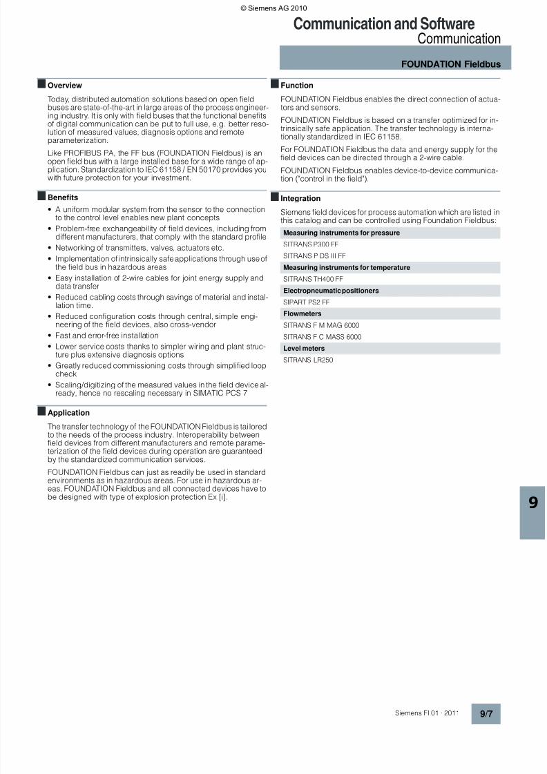
FOUNDATION Fieldbus enables the direct connection of actua-tors and sensors.
FOUNDATION Fieldbus is based on a transfer optimized for in-trinsically safe application. The transfer technology is interna-
tionally standardized in IEC 61158.
For FOUNDATION Fieldbus the data and energy supply for thefield devices can be directed through a 2-wire cable.
FOUNDATION Fieldbus enables device-to-device communica-tion ("control in the field").
■ Integration
Siemens field devices for process automation which are listed inthis catalog and can be controlled using Foundation Fieldbus:
Measuring instruments for pressure
SITRANS P300 FF
SITRANS P DS III FF
Measuring instruments for temperatureSITRANS TH400 FF
Electropneumatic positioners
SIPART PS2 FF
Flowmeters
SITRANS F M MAG 6000
SITRANS F C MASS 6000
Level meters
SITRANS LR250
© Siemens AG 2010

8/3/2019 Procesne Kominikacije i Softveri
http://slidepdf.com/reader/full/procesne-kominikacije-i-softveri 8/18
Communication and SoftwareWirelessHART Communication
Communication blocks
9/8 Siemens FI 01 · 2011
■Overview
The WirelessHART communication blocks implement the com-munication between S7/PCS 7 automation systems and Wire-lessHART field devices. They communicate via theIE/WSN-PA LINK using the Modbus TCP/IP protocol. Preconfig-ured communication blocks simplify the engineering process.Symbols and face plates are included in the delivery for use withSIMATIC PCS 7 OS or SIMATIC WinCC.
■Benefits
A library, which can be installed, offers pre-fabricated blocksand hence an easy way to integrate WirelessHART devices intothe SIMATIC automation world.
Simple configuration thanks to:
• Prefabricated function blocks for IE/WSN-PA LINK and Wire-lessHART devices
• SIMATIC PCS 7 OS or SIMATIC WinCC symbols and faceplates are included
• Configuring help for IE/WSN-PA LINK in line with functionblocks
• Output of quality codes for respective process values
• Analysis of IE/WSN-PA LINK diagnostic information
■Application
WirelessHART communication blocks are used where SIMATICautomation systems communicate with WirelessHART devicesvia the IE/WSN-PA LINK gateway.
■ Function
The function blocks cyclically communicate with theIE/WSN-PA LINK via Modbus TCP/IP. Process values ofWirelessHART devices as well as their status are read and madeavailable at the function block outputs. Furthermore, selected
status information of the IE/WSN-PA LINK is also made availableat another building block. This information includes connectionstatus, condition of the wireless network and other diagnostics.Precondition of the usage of these communication blocks is aTCP/IP connection, engineered in NetPro in the Engineering Sta-tion of Simatic PCS 7. Currently this requires a CP343 or aCP443-1.
■Configuration
The standard S7 or PCS 7 engineering tools CFC, KOP, FUP canbe used for the communication block engineering. Connectionplanning is done in NetPro. A configuration example for config-uring the IE/WSN-PA LINK makes it easy to assign theWirelessHART devices to the communication blocks which needto be engineered.
■More information
You can obtain function blocks and technical support for inte-grating the IE/WSN-PA LINK in PCS 7 at the following address:
Siemens AGIndustry SectorIndustry Solutions DivisionIndustrial TechnologiesRoland HeidSiemensallee 8476187 KarlsruheGermanyTel: +49 721 595-6380E-Mail: [email protected]
■Selection and ordering Data
HMI
Communication block
WirelessHART adapter
SITRANS P280
IE/WSN-PA LINK
SIMATIC S7-400
SIMATIC S7-300
SITRANS TF280
Industrial Ethernet
Order No.
S7/PCS 7 function blocks forcommunicating with Wire-lessHART devices using theIE/WSN-PA LINK
9AE4110-3AA00
S7-300 or S7-400,including face plate
© Siemens AG 2010

8/3/2019 Procesne Kominikacije i Softveri
http://slidepdf.com/reader/full/procesne-kominikacije-i-softveri 9/18
Communication and SoftwareWirelessHART Communication
SITRANS MDS - Maintenance Diagnostic Station
9/9Siemens FI 01 · 2011
■Overview
Maintenance Diagnostic Station
SITRANS MDS for flexible and automated diagnostic process-ing:
• Central display of diagnostic information from HART devices,which was only readable on site until now.
• Adjustable updating period for each device
• Clear visualization of diagnostic status of all devices
• Simply transfer of SIMATIC PDM configuring data
• Windows-based application
■Benefits
SITRANS MDS in cooperation with SIMATIC PDM increases sig-nificantly the transparency of a plant.
The main advantages of SIMATIC MDS are as follows:
• Increase transparency of the plant by reading diagnostic infor-mation from accessible devices and providing a well-orga-nized representation of this information
• Representation of diagnostic status of a device as inSIMATIC PCS 7 or NAMUR NE 107 (switchable)
• Ease of use through use of SIMATIC PDM project data
• The update cycle for the diagnostic status can be uniformlyset as the default value for all devices ...
• ... as well as for each device individually
■Application
SITRANS MDS increases the transparency of a plant by centrallycollecting diagnostic information, directly from the accessiblefield devices. In principle, all devices that are integrated in
SIMATIC PDM can be included in the collecting process.
SITRANS MDS can be used where the installed automation sys-tem does not support an integrated acyclic communication ofparameters and diagnostic information with the devices. In thecase of HART devices, this applies to 85% of all installeddevices.
The modern SIMATIC PCS 7 process control system allows forthis type of continuous communication from the engineering sys-tem up to the devices. It also features a decidedly higher perfor-mance asset management system. The use of SIMATIC MDStherefore does not make sense in a SIMATIC PCS 7 environmentand is hence not approved for that purpose.
■Design
SITRANS MDS uses SIMATIC PDM project data to read anddisplay diagnostic data from accessible devices.
■ Integration
SITRANS MDS is installed on a PC together with SIMATIC PDM.Only the stand-alone version is used in this case.
■Configuration
Configuration required for SITRANS MDS is adopted fromSIMATIC PDM. Only the project name must be entered.
Very few other entries are required, such as the definition ofupdate periods.
■ Technical specifications
SITRANS MDS Maintenance Diagnostic Station
Operating system Microsoft Windows XPprofessional SP2/SP3
Additionally required software
SIMATIC PDM as of V 6.05 andoptions
• SIMATIC PDM Basic (4Tags) 6ES7 658-3AX06-0YA5
• SIMATIC PDM service (128 Tags) 6ES7 658-3JX06-0YA5
• SIMATIC PDM Option HART Mux 6ES7 658-3EX06-0YB5
Additional options to increasenumber of measuring points
Controller without
HART support
Remote I/O station
w/o HART support
SITRANS
MDS OS
IE/WSN-
PA LINK
SITRANS
AW200
Industrial
Ethernet
Industrial Ethernet
P R O F I B U S
Wireless
HART
IWLAN
IEEE802.11
4–20 mA
4–20 mA
4–20 mA
© Siemens AG 2010

8/3/2019 Procesne Kominikacije i Softveri
http://slidepdf.com/reader/full/procesne-kominikacije-i-softveri 10/18
Communication and SoftwareWirelessHART Communication
SITRANS MDS - Maintenance Diagnostic Station
9/10 Siemens FI 01 · 2011
■Selection and Ordering data
SITRANS MDS is a software package which is delivered togetherwith the IE/WSN-PA LINK for Version 1.0.
PC hardware 600 MHz256 MB *)XGA 1024 x 76816 Bit color depth
*) main memory of at least512 MB is recommended
Up-to-date information can befound in the description forSIMATIC PDM
© Siemens AG 2010

8/3/2019 Procesne Kominikacije i Softveri
http://slidepdf.com/reader/full/procesne-kominikacije-i-softveri 11/18
Communication and SoftwareSoftware
SIMATIC PDMProcess Device Manager
9/11Siemens FI 01 · 2011
■Overview
Configuration options with SIMATIC PDM
SIMATIC PDM (Process Device Manager) is a universal, vendor-independent tool for the configuration, parameterization, com-missioning, diagnostics and servicing of intelligent field devices(sensors and actuators) and field components (remote I/Os,multiplexers, control-room devices, compact controllers), whichin the following sections will be referred to simply as devices.
Using one software, SIMATIC PDM enables the processing ofmore than 1 300 devices from Siemens and over 120 vendorsworldwide on one homogeneous user interface. Parameters andfunctions for all supported devices are displayed in a consistentand uniform fashion independent of their communications inter-face.
From the viewpoint of device integration, SIMATIC PDM is themost powerful open device manager available in the world. De-vices which previously were not supported can be easily inte-grated in SIMATIC PDM at any time by importing their device de-scriptions (EDD). This provides security for your investment andsaves you investment costs, training expenses and consequen-tial costs.
SIMATIC PDM is integrated in the asset management of SIMATICPCS 7. The Process Device Manager provides wider informationfor all devices described by the Electronic Device Description(EDD), e.g. detailed diagnostics information (vendor informa-tion, information on fault diagnostics and troubleshooting, furtherdocumentation), modification logbook (audit trial), parameter in-formation. It is possible to change directly to SIMATIC PDM fromthe diagnostics faceplates in the maintenance station.
S7-400
PROFIBUS PA
SITRANS P
DS III PA
SITRANS
TH400
SITRANS LR SITRANS F M
SIMOCODE
pro
MICROMASTER
ET
200iSP
S7-400
SIPART PS2
SIPART PS2
H A R T
RS 232/RS 485
SITRANS P
SITRANS P
DSIII HART
Plant bus
DP/PA
link
SIMATIC PCS 7 engineering station
with SIMATIC PDM
PROFIBUS DP fieldbus Up to 12 Mbit/s
Possible connection point of a PG/PC with SIMATIC PDM (stand-alone operation)
HART
multiplexer
Stand-alone
computer
with SIMATIC PDM
Device on
the workbench
HART protocol
ET 200M
(IM 153-2 with
HART modules)
© Siemens AG 2010

8/3/2019 Procesne Kominikacije i Softveri
http://slidepdf.com/reader/full/procesne-kominikacije-i-softveri 12/18
Communication and SoftwareSoftwareSIMATIC PDMProcess Device Manager
9/12 Siemens FI 01 · 2011
■Application
Table with SIMATIC PDM product structureNote: For definition of TAG, see under TAG options/PowerPacks
Customer-oriented product structure
The SIMATIC PDM Process Device Manager can be used in aversatile manner in the context of Totally Integrated Automation(TIA). Use in the engineering system of SIMATIC PCS 7 is onepossible application.
The customer-oriented products structure of SIMATIC PDMsupports you in adaptation of the scope of functions andperformance to your individual requirements. You can select
the minimum configuration SIMATIC PDM Single Point, one ofthe application-specific, predefined product configurationsSIMATIC PDM Service, SIMATIC PDM PCS 7 or SIMATIC PDMS7, or produce your desired configuration from the individualcomponents offered (see table).
The selection depends on the application range and environ-ment of use:
• System-integrated in a SIMATIC PCS 7/S7 configuration envi-ronment:- SIMATIC PDM PCS 7 (for integration in an engineering sys-
tem for SIMATIC PCS 7)- SIMATIC PDM S7 (for integration in a SIMATIC S7 configura-
tion environment)
• SIMATIC PDM stand-alone as service tool for operation on amobile computer on the PROFIBUS or with direct connectionto the device:- SIMATIC PDM Single Point (for processing of a single field
device via a point-to-point coupling)- SIMATIC PDM Service (for enhanced servicing, including
modification logbook and lifelist detailed diagnostics)
■Design
Minimum configuration SIMATIC PDM Single Point
This low-cost minimum configuration with handheld functionalityis tailored to processing exactly one field device via a point-to-point coupling. All device functions are supported as defined inthe device description. These functions include:
• Unlimited selection of devices / management of device cata-log
• Communication via PROFIBUS DP/PA or HART modem
• Parameterization and diagnostics in accordance with the de-vice description
• Exporting and importing of parameter data
• Device identification
• Lifelist
The following system functions of SIMATIC PDM Basic are notavailable with SIMATIC PDM Single Point:
• EDD-based diagnostics in the lifelist
• Project editing
• Storage function (only exporting and importing of parameterdata)
• Recording functions
• Routing
• Communication with HART field devices via remote I/Os
The functions of SIMATIC PDM Single Point cannot be extended(e.g. to SIMATIC PDM Basic or with the routing option throughS7-400), nor can it be expanded with TAG options or Power-Packs.
SIMATIC PDM
product structure
SIMATIC PDM stand-alone SIMATIC PDM system-integrated
Minimum
configuration
Components for indi-
vidual configurationPredefined product configurations
Product name SIMATIC PDMSingle Point
SIMATIC PDMBasic
SIMATIC PDMService
SIMATIC PDMS7
SIMATIC PDMPCS 7
Components/TAGs included in
scope of delivery1 4
SIMATIC PDM Basic/
128
SIMATIC PDM Basic/
128
SIMATIC PDM Basic/
128
TAG expansions
Not
expandable
TAG options
- 128 TAGs
- 512 TAGs
- 1 024 TAGs
- 2 048 TAGs
and/or PowerPacks
PowerPacks
- From 128 to 512 TAGs
- From 512 to 1 024 TAGs
- From 1 024 to 2 048 TAGs
- From 2 048 to unlimited TAGs
Option
"Integration in STEP 7/PCS 7"○ ○ ● ●
Option "Routing through S7-400" ○ ○ ○ ●Option "Communication through
standard HART multiplexer" ○ ○ ○ ○
● Components included in delivery of individual PDM configurations
○ Can be ordered as options
© Siemens AG 2010
8/3/2019 Procesne Kominikacije i Softveri
http://slidepdf.com/reader/full/procesne-kominikacije-i-softveri 13/18
Communication and SoftwareSoftware
SIMATIC PDMProcess Device Manager
9/13Siemens FI 01 · 2011
Predefined product configurations
SIMATIC PDM Service
This is a predefined product configuration especially for mobileuse in servicing for projects with up to 128 TAGs. It offers serviceengineers all functions of SIMATIC PDM Basic, including changelog, calibration report and detailed diagnostics in the l ifelist.
The following program components are part of SIMATIC PDMService:
• SIMATIC PDM Basic
• Option: 128 TAGs
SIMATIC PDM Service can be expanded by the functional op-tions "Integration in STEP 7/PCS 7", "Routing through S7-400"and "Communication via standard HART multiplexer" as wellas by SIMATIC PDM PowerPacks (see under TAG options/PowerPacks, page 3/16).
SIMATIC PDM PCS 7
SIMATIC PDM PCS 7 is a predefined product configuration forintegration into the engineering system (engineering tool set)and the maintenance station of SIMATIC PCS 7. The product ver-
sion designed for projects with up to 128 TAGs allows the use ofall functions of SIMATIC PDM Basic (including change log, cali-bration report and detailed diagnostics in the lifelist). In addition,it contains the functionality for integration of the SIMATIC PDMinto HW-Config as well as the routing from the central engineer-ing system to the field devices.
The following program components are part of SIMATIC PDMPCS 7:
• SIMATIC PDM Basic
• Option: 128 TAGs
• Option: Integration in STEP 7/SIMATIC PCS 7
• Option: Routing through S7-400
SIMATIC PDM PCS 7 can be expanded by the option "Commu-nication via standard HART multiplexer" and by SIMATIC PDM
PowerPacks (see under TAG options/PowerPacks, page 3/16).SIMATIC PDM S7
SIMATIC PDM S7 is a predefined product configuration tailoredto the use of SIMATIC PDM in a SIMATIC S7 configuration envi-ronment. It offers all functions of SIMATIC PDM Basic (includingchange log, calibration report and detailed diagnostics in thelifelist) as well as the functionality for integration of PDM inHW-Config.
The following program components are part of SIMATICPDM S7:
• SIMATIC PDM Basic
• Option: 128 TAGs
• Option: Integration in STEP 7/SIMATIC PCS 7
SIMATIC PDM S7 can be expanded by the functional options"Routing through S7-400" and "Communication via standardHART multiplexer" as well as by SIMATIC PDM PowerPacks (seeunder TAG options/PowerPacks, page 3/16).
Components for individual configuration
SIMATIC PDM Basic
SIMATIC PDM Basic is the basic component for production of in-dividual SIMATIC PDM configurations from single components.It contains all functions required for operation and parameteriza-tion of the devices, as well as enabling for the following commu-nication modes:
• PROFIBUS DP/PA
• HART communication (modem, RS 232 and PROFIBUS)
• MODBUS
• SIREC bus• SIPART DR
SIMATIC PDM Basic without TAG expansion can manage proj-ects with as many as 4 TAGs and, provided the system require-ments are met, can be used for stand-alone operation on anycomputers (PCs/notebooks) with local connection to bus seg-ments or with direct connection to the device.
SIMATIC PDM Basic can be expanded by functional options and
TAG options/PowerPacks. Use of the following functions requiresat least 128 TAGs:
• Change log
• Calibration report
• Detailed diagnostics in the lifelist
SIMATIC PDM Basic is also available in the form of a rental li-cense for 50 operating hours for low-cost processing of short-term projects.
SIMATIC PDM option: Integration in STEP 7/PCS 7
This option is required for use of SIMATIC PDM within aSIMATIC S7 or SIMATIC PCS 7 project with a local connection tothe PROFIBUS. SIMATIC PDM can then be started directly fromthe hardware project (HW-Config).
SIMATIC PDM option: Routing through S7-400This option is required additive to the option "Integration inSTEP7/PCS 7" if SIMATIC PDM is to be used in a engineeringsystem for SIMATIC PCS 7/S7 with Ethernet bus connection tothe automation systems for plant-wide configuration, parameter-ization, commissioning and diagnostics of field devices.
SIMATIC PDM option: Communication via standardHART multiplexer
This option permits SIMATIC PDM to use the HART OPC serverfor communication with HART field devices via HART multiplex-ers.
TAG options/PowerPacks
A TAG corresponds to a SIMATIC PDM object, which representsindividual field devices or components within a project, e.g.
measuring instruments, positioners, switching devices or remoteI/Os. TAGs are also relevant for diagnostics with the l ifelist ofSIMATIC PDM. In this case, TAGs are considered to be all rec-ognized devices with diagnostics capability, whose detaileddiagnostics is effected through the device description (EDD).
In contrast to PowerPacks, TAG options are only suitable forproduct configurations on the basis of individual components.Using the SIMATIC PDM TAG options, the basic softwareSIMATIC PDM Basic can be expanded from 4 TAGs to 128, 512,1 024 or 2 048 TAGs, and with the help of an additive PowerPackalso to unlimited TAGs.
The number of available TAGs can be subsequently increasedfor all SIMATIC PDM product configurations by means of theSIMATIC PDM PowerPacks. PowerPacks are available for ex-pansion to 512, 1 024, 2 048 and unlimited TAGs.
Demonstration software
A demonstration version of SIMATIC PDM is also available.Online communication and storage functions are not availablewith this version.
© Siemens AG 2010

8/3/2019 Procesne Kominikacije i Softveri
http://slidepdf.com/reader/full/procesne-kominikacije-i-softveri 14/18
Communication and SoftwareSoftwareSIMATIC PDMProcess Device Manager
9/14 Siemens FI 01 · 2011
■ Function
Parameter view of SIMATIC PDM with trend curve and online display
Core functions
• Adjustment and modification of device parameters
• Comparing (e.g. project and device data)
• Plausibility testing of data input
• Device identification and testing
• Device status indication with operating modes, alarms andstates
• Simulation
• Diagnostics (standard, detailed)
• Management (e.g. networks and PCs)
• Export/import (parameter data, reports)
• Commissioning functions, e.g. measuring circuit tests of de-vice data
• Device replacement (lifecycle management)
• Global and device-specific modification logbook for useroperations (audit trail)
• Device-specific calibration reports
• Graphic presentations of echo envelope curves, trend dis-plays, valve diagnosis results etc.
• Presentation of incorporated manuals
• Document manager for integration of up to 10 multimedia files
Support of system management
SIMATIC PDM supports the operative system management inparticular through:
• Uniform presentation and operation of devices
• Indicators for preventive maintenance and servicing
• Detection of changes in the project and device
• Increasing the operational reliability• Reducing the investment, operating and maintenance costs
• Graded user privileges including password protection
PDM lifelist with status and diagnostics display
Graphical user interface
The GUI of SIMATIC PDM satisfies the requirements of the direc-tives VDI/VDE GMA 2187 and IEC 65/349/CD. Even complex de-vices with several hundred parameters can thus be represented
clearly and processed quickly. Using SIMATIC PDM it is veryeasy to navigate in highly complex stations such as remote I/Osand even connected field devices.
Several views are available to users to help them with their tasks:
• Hardware project view
• Process device network view (preferably for stand-alone ap-plication)
• Process device plant view as TAG-related view, also with dis-play of diagnostics information
• Parameter view for parameterizing the field devices
• Lifelist view for commissioning and service
Communication
SIMATIC PDM supports several communication protocols and
components for communicating with devices that have the fol-lowing interfaces:
• PROFIBUS DP/PA interface
• HART interface
• Modbus interface
• Special interface from Siemens
Further communication protocols on request.
Routing
From the central engineering system of the SIMATIC PCS 7 pro-cess control system, you can navigate with SIMATIC PDMthrough the various bus systems and remote I/Os down to theconnected devices. Throughout the plant, every device whichcan be parameterized per EDD can be processed using this
routing functionality. The following processing functions areavailable:
• Read diagnostics information from the device
• Modify device settings
• Adjust and calibrate devices
• Monitor process values
• Generate simulation values
• Reparameterize devices
© Siemens AG 2010
8/3/2019 Procesne Kominikacije i Softveri
http://slidepdf.com/reader/full/procesne-kominikacije-i-softveri 15/18
Communication and SoftwareSoftware
SIMATIC PDMProcess Device Manager
9/15Siemens FI 01 · 2011
■ Integration
Device Integration
SIMATIC PDM supports all devices described by EDD (Elec-tronic Device Description). EDD is standardized to EN 50391and IEC 61804. Internationally it is the most widely used stan-
dardized technology for device integration. At the same time it isthe directive of the established organizations for PROFIBUS(PNO: PROFIBUS International) and HART (HCF: HART Commu-nication Foundation).
The devices are directly integrated in SIMATIC PDM throughtheir EDD or the current HCF catalog. In the EDD the device isdescribed in terms of its functions and construction using theElectronic Device Description Language (EDDL) specified byPNO. Using this description, SIMATIC PDM automatically cre-ates its user interface with the specific device data.
The current device catalog of SIMATIC PDM covers more than1 300 devices from more than 120 manufacturers world-wide. Inaddition, devices from all manufacturers can be integrated inSIMATIC PDM by simply importing their EDDs. It is thus possibleto keep the device range up to date at all times and to add to the
number of manufacturers and devices supported by SIMATICPDM. To permit improved transparency, SIMATIC PDM also al-lows the creation of project-specific device catalogs. If devicesare to be used which cannot be found in the SIMATIC PDM de-vice catalog, we will be glad to help you integrate them.
Contact addresses
Siemens AG, Automation and Drives,Technical Support
Europe
Phone: +49 180 50 50 222Fax: +49 180 50 50 223E-mail: FPlease fill in a Support Request on the Internet(see below for address)
Asia/Pacific
Phone: +86 1064 719 990Fax: +86 1064 747 474E-mail: [email protected]
America
Phone: +1 423 262 2522Fax: +1 423 262 2200E-mail: [email protected]
Support Request
You can also obtain corresponding support over the Internet perSupport Request:
www.siemens.com/automation/support-request
■ Technical specifications
Hardware minimum requirements • PG/PC/notebook with processorcorresponding to operating sys-tem requirements
• Main memory 256 MB
• Vacant hard disk 370 MBOperating systems (alternative) • Microsoft Windows 2000 Profes-
sional SP3/SP4
• Microsoft Windows XP Profes-sional SP2/SP3
• Microsoft Windows Server 2003SP2 (only for operation with aSIMATIC PCS 7 EngineeringStation)
Further software components
• SIMATIC PDM option "Integrationin STEP 7/PCS 7"
STEP 7 V5.2 + SP1
STEP 7 V5.3 + SP3
STEP 7 V5.4 + SP4
SIMATIC PCS 7 V6.1 + SP2/SP3
SIMATIC PCS 7 V7.0 + SP2
SIMATIC PCS 7 V7.1
© Siemens AG 2010
8/3/2019 Procesne Kominikacije i Softveri
http://slidepdf.com/reader/full/procesne-kominikacije-i-softveri 16/18
Communication and SoftwareSoftwareSIMATIC PDMProcess Device Manager
9/16 Siemens FI 01 · 2011
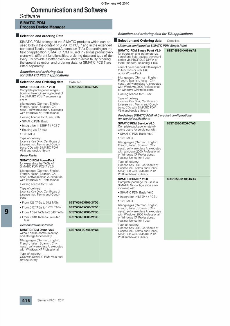
■Selection and ordering Data
SIMATIC PDM belongs to the SIMATIC products which can beused both in the context of SIMATIC PCS 7 and in the extendedcontext of Totally Integrated Automation (TIA). Depending on thefield of application, SIMATIC PDM is used in various product ver-
sions with different functionalities, ordering data and type of de-livery. To provide a better overview and to avoid faulty ordering,the special selection and ordering data for SIMATIC PCS 7 arelisted separately.
Selection and ordering data for SIMATIC PCS 7 applications
Selection and ordering data for TIA applications
■Selection and Ordering data Order No.
SIMATIC PDM PCS 7 V6.0Complete package for integra-tion into the engineering toolset ofthe SIMATIC PCS 7 engineeringsystem
6 languages (German, English,French, Italian, Spanish, Chi-nese), software class A, executes
with Windows XP ProfessionalFloating license for 1 user, with
• SIMATIC PDM Basic
• Integration in STEP 7 / PCS 7
• Routing via S7-400
• 128 TAGs
Type of delivery:License Key Disk, Certificate ofLicense incl. Terms and Condi-tions; CDs with SIMATIC PDMV6.0 and device library
6ES7 658-3LX06-0YA5
PowerPacks
SIMATIC PDM PowerPackfor expanding the TAGs ofSIMATIC PDM PCS 7 V6.0
6 languages (German, English,French, Italian, Spanish, Chi-nese),software class A, executeswith Windows XP Professional
Floating license for 1 user
Type of delivery:License Key Disk, Certificate ofLicense incl. Terms and Condi-tions
• From 128 TAGs to 512 TAGs 6ES7 658-3XB06-2YD5
• From 512 TAGs to 1 024 TAGs 6ES7 658-3XC06-2YD5
• From 1 024 TAGs to 2 048 TAGs 6ES7 658-3XD06-2YD5
• From 2 048 TAGs to unlimitedTAGs
6ES7 658-3XH06-2YD5
Demonstration software
SIMATIC PDM Demo V6.0without online communicationand storage functionality
6 languages (German, English,French, Italian, Spanish, Chi-nese), software class A, executeswith Windows XP Professional
Type of delivery:CDs with SIMATIC PDM V6.0 anddevice library
6ES7 658-3GX06-0YC8
■Selection and Ordering data Order No.
Minimum configuration SIMATIC PDM Single Point
SIMATIC PDM Single Point V6.0for operation and parameteriza-
tion of one field device; communi-cation via PROFIBUS DP/PA orHART modem, including 1 TAG
cannot be expanded with respectto functions or with TAGoption/PowerPack
6 languages (German, English,French, Spanish, Italian, Chi-nese), software class A, executeswith Windows 2000 Professionalor Windows XP Professional
Floating license for 1 user
Type of delivery:License Key Disk, Certificate ofLicense incl. Terms and Condi-tions; CDs with SIMATIC PDMV6.0 and device library
6ES7 658-3HX06-0YA5
Predefined SIMATIC PDM V6.0 product configurations for special applications
SIMATIC PDM Service V6.0Complete package for stand-alone users for servicing, with
• SIMATIC PDM Basic V6.0
• 128 TAGs
6 languages (German, English,French, Italian, Spanish, Chi-nese), software class A, executeswith Windows 2000 Professionalor Windows XP Professional,floating license for 1 user
Type of delivery:License Key Disk, Certificate ofLicense incl. Terms and Condi-
tions; CDs with SIMATIC PDMV6.0 and device library
6ES7 658-3JX06-0YA5
SIMATIC PDM S7 V6.0Complete package for use in aSIMATIC S7 configuration envi-ronment, with
• SIMATIC PDM Basic V6.0
• Integration in STEP 7 / PCS 7
• 128 TAGs
6 languages (German, English,French, Italian, Spanish, Chi-nese), software class A, executeswith Windows 2000 Professionalor Windows XP Professional,floating license for 1 user
Type of delivery:
License Key Disk, Certificate ofLicense incl. Terms and Condi-tions; CDs with SIMATIC PDMV6.0 and device library
6ES7 658-3KX06-0YA5
© Siemens AG 2010

8/3/2019 Procesne Kominikacije i Softveri
http://slidepdf.com/reader/full/procesne-kominikacije-i-softveri 17/18
8/3/2019 Procesne Kominikacije i Softveri
http://slidepdf.com/reader/full/procesne-kominikacije-i-softveri 18/18
Communication and SoftwareSoftware
© Siemens AG 2010