product guide: electricity monitoring …eyedro.com/media/docs/eyedro-ems-product-guide.pdf ·...
TRANSCRIPT
REV: K
PRODUCT GUIDE:
ELECTRICITY MONITORING PRODUCTS
PRODUCT GUIDE: EYEDRO ELECTRICITY MONITORING PRODUCTS
©2011-2018 Eyedro Green Solutions Inc. P a g e | 2
CONTENTS Introduction.................................................................................................................................................... 4
Overview .................................................................................................................................................... 4
Important Safety Information ..................................................................................................................... 5
Box Contents (By Product)............................................................................................................................ 7
Eyedro Home (EH*) ................................................................................................................................... 7
Eyedro Business (EB*) .............................................................................................................................. 8
Hardware Installation .................................................................................................................................... 9
Locating the Electrical Service .................................................................................................................. 9
Service Box and Distribution Panel ....................................................................................................... 9
Combination Service/Distribution Panel ................................................................................................ 9
Install Current Sensors ............................................................................................................................ 10
Materials You Will Need....................................................................................................................... 10
Tools You Will Need ............................................................................................................................ 10
Procedure (Typical Service Entrance Monitoring) ............................................................................... 10
Procedure (Alternate Applications) ...................................................................................................... 11
Measure Line Voltage (Optional) ............................................................................................................. 15
Materials You Will Need....................................................................................................................... 15
Tools You Will Need ............................................................................................................................ 15
Procedure (Typical Residential Installation) ........................................................................................ 15
Align Wireless Modules (E*W* Products Only) ....................................................................................... 16
Mount Eyedro Device(s) .......................................................................................................................... 17
Materials You Will Need....................................................................................................................... 17
Tools You Will Need ............................................................................................................................ 17
Procedure (Vertical Mount) .................................................................................................................. 17
Procedure (Horizontal Mount) .............................................................................................................. 18
Connect Cabling ...................................................................................................................................... 19

PRODUCT GUIDE: EYEDRO ELECTRICITY MONITORING PRODUCTS
©2011-2018 Eyedro Green Solutions Inc. P a g e | 3
Materials You Will Need....................................................................................................................... 19
Tools You Will Need ............................................................................................................................ 19
Procedure (Wired Installations) ........................................................................................................... 19
Procedure (Wireless Installations) ....................................................................................................... 20
Internet Connection ..................................................................................................................................... 21
Software Configuration ................................................................................................................................ 22
MyEyedro.com ......................................................................................................................................... 22
Specifications .............................................................................................................................................. 23
Hardware Specifications .......................................................................................................................... 23
Sensor Specifications .............................................................................................................................. 24
Compliance ................................................................................................................................................. 25
Warranty ...................................................................................................................................................... 26
Contact Information ..................................................................................................................................... 27
Appendix A: Troubleshooting ...................................................................................................................... 28
No Power (all devices) ............................................................................................................................. 29
No Communication – Part A Verify Internet Connectivity (wired and gateway devices) ......................... 31
No Communication – Part B Verify Wireless Connectivity (wireless devices) ........................................ 35
Intermittent Communication/Measurements ............................................................................................ 38
Unexpected Measurements..................................................................................................................... 40
PRODUCT GUIDE: EYEDRO ELECTRICITY MONITORING PRODUCTS
©2011-2018 Eyedro Green Solutions Inc. P a g e | 4
INTRODUCTION
OVERVIEW
Eyedro Green Solutions Inc. is a software and electronics design company making electricity usage easy to understand. We provide simple solutions for monitoring your electricity in real-time.
Combined with the MyEyedro cloud service, Eyedro is an affordable, easy to install and scalable electricity monitor for your home and business. Join thousands of customers already using Eyedro to keep an eye on their electricity use.
Thank you for choosing the Eyedro Electricity Monitoring System. You have taken the first step towards better awareness of where your energy is being consumed. Awareness can lead to energy savings, cost savings and peace of mind.
The Eyedro Electricity Monitoring System will help you keep an eye on your electrical consumption. Its non-invasive design measures electrical current supplied to the building and computes the power consumed. Data is stored on a remote server 24 hours a day - 7 days a week - 365 days a year. There is no need to worry about losing your data or running out of storage space. Your data is available for review from anywhere you have access to the internet - at home, at work or on the go! The easy to use interface allows you to view your current and historical data, daily averages, bill to date and even predict what your total bill will look like. Use the browser on your mobile phone to walk through your house switching appliances on and off – you may be surprised what you learn!
The Eyedro Electricity Monitoring System will help you realize just how much electricity you are wasting every day and how much money you could save by reducing that waste. You will soon realize that simple changes in your habits – like turning off lights, unplugging unused equipment, or dialing back the thermostat – will result in less consumption and more money in your pocket.
If you have any questions about using your Eyedro Electricity Monitoring System please visit eyedro.com for information, documentation, videos and answers to frequently asked questions.
PRODUCT GUIDE: EYEDRO ELECTRICITY MONITORING PRODUCTS
©2011-2018 Eyedro Green Solutions Inc. P a g e | 5
IMPORTANT SAFETY INFORMATION
It is important that you observe some simple safety precautions when installing this product. The Eyedro Electricity Monitor was designed to be non-intrusive and easy to install. Typically, there is no need to disconnect any electrical cabling during the installation. However, there are a number of safety issues that should be considered when installing and using the system.
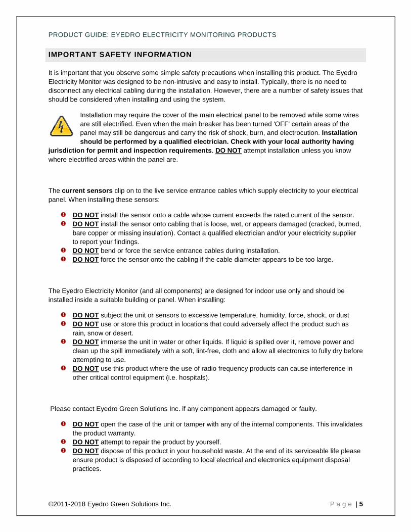
Installation may require the cover of the main electrical panel to be removed while some wires are still electrified. Even when the main breaker has been turned 'OFF' certain areas of the panel may still be dangerous and carry the risk of shock, burn, and electrocution. Installation should be performed by a qualified electrician. Check with your local authority having
jurisdiction for permit and inspection requirements. DO NOT attempt installation unless you know where electrified areas within the panel are.
The current sensors clip on to the live service entrance cables which supply electricity to your electrical panel. When installing these sensors:
DO NOT install the sensor onto a cable whose current exceeds the rated current of the sensor. DO NOT install the sensor onto cabling that is loose, wet, or appears damaged (cracked, burned,
bare copper or missing insulation). Contact a qualified electrician and/or your electricity supplier to report your findings.
DO NOT bend or force the service entrance cables during installation. DO NOT force the sensor onto the cabling if the cable diameter appears to be too large.
The Eyedro Electricity Monitor (and all components) are designed for indoor use only and should be installed inside a suitable building or panel. When installing:
DO NOT subject the unit or sensors to excessive temperature, humidity, force, shock, or dust DO NOT use or store this product in locations that could adversely affect the product such as
rain, snow or desert. DO NOT immerse the unit in water or other liquids. If liquid is spilled over it, remove power and
clean up the spill immediately with a soft, lint-free, cloth and allow all electronics to fully dry before attempting to use.
DO NOT use this product where the use of radio frequency products can cause interference in other critical control equipment (i.e. hospitals).
Please contact Eyedro Green Solutions Inc. if any component appears damaged or faulty.
DO NOT open the case of the unit or tamper with any of the internal components. This invalidates the product warranty.
DO NOT attempt to repair the product by yourself. DO NOT dispose of this product in your household waste. At the end of its serviceable life please
ensure product is disposed of according to local electrical and electronics equipment disposal practices.
PRODUCT GUIDE: EYEDRO ELECTRICITY MONITORING PRODUCTS
©2011-2018 Eyedro Green Solutions Inc. P a g e | 6
The following notes apply to Eyedro Wireless products:
This equipment has been tested and found to comply with the limits for a Class A digital device, pursuant to part 15 of the FCC Rules. These limits are designed to provide reasonable protection against harmful interference in a residential installation. This equipment generates, uses and can radiate radio frequency energy, and if not installed and used in accordance with the instructions, may cause harmful interference to radio communications. However, there is no guarantee that interference will not occur in a particular installation. If this equipment does cause harmful interference to radio or television reception, which can be determined by turning the equipment off and on, the user is encouraged to try to correct the interference by one or more of the following measures:
Reorient or relocate the receiving antenna.
Increase the separation between the equipment and receiver.
Connect the equipment into an outlet on a circuit different from that to which the receiver is connected.
Consult the dealer or an experienced radio/TV technician for help.
To satisfy FCC RF Exposure requirements for mobile and base station transmission devices, a separation distance of 20 cm or more should be maintained between the antenna of this device and persons during operation. To ensure compliance, operation at closer than this distance is not recommended. The antenna(s) used for this transmitter must not be co-located or operating in conjunction with any other antenna or transmitter.

PRODUCT GUIDE: EYEDRO ELECTRICITY MONITORING PRODUCTS
©2011-2018 Eyedro Green Solutions Inc. P a g e | 7
BOX CONTENTS (BY PRODUCT)
EYEDRO HOME (EH*)
IMPORTANT Eyedro Home Wired/Wireless Electricity Monitoring (EH*) products should not be installed in applications where the supply voltage exceeds 300V AC. For applications requiring greater voltage rating (up to 600V), Eyedro Business Wired/Wireless Electricity Monitoring (EB*) products must be used.
A B C D
Wired Wireless Description
A 1 - Eyedro Combo Module - 1 Eyedro Sensor Module - 1 Eyedro Gateway Module
B 2 2 200A Current Sensors C 1 2 Low-voltage Power Adapter D 10ft (3m) 3ft (0.9m) Ethernet Cable
PRODUCT GUIDE: EYEDRO ELECTRICITY MONITORING PRODUCTS
©2011-2018 Eyedro Green Solutions Inc. P a g e | 8
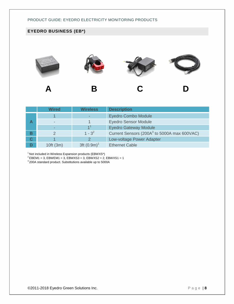
EYEDRO BUSINESS (EB*)
A B C D
Wired Wireless Description
A 1 - Eyedro Combo Module - 1 Eyedro Sensor Module - 11 Eyedro Gateway Module
B 2 1 - 32 Current Sensors (200A3 to 5000A max 600VAC) C 1 2 Low-voltage Power Adapter D 10ft (3m) 3ft (0.9m)1 Ethernet Cable
1 Not included in Wireless Expansion products (EBWXS*) 2 EBEM1 = 3, EBWEM1 = 3, EBWXS3 = 3, EBWXS2 = 2, EBWXS1 = 1 3 200A standard product. Substitutions available up to 5000A

PRODUCT GUIDE: EYEDRO ELECTRICITY MONITORING PRODUCTS
©2011-2018 Eyedro Green Solutions Inc. P a g e | 9
HARDWARE INSTALLATION
DO NOT CONTINUE WITH THE INSTALLATION OF THE EYEDRO ELECTRICITY MONITORING SYSTEM UNTIL YOU HAVE READ THE SAFETY SECTION OF THIS GUIDE.
LOCATING THE ELECTRICAL SERVICE
The electricity panel is typically located in the garage or utility room of the building – although this is not always the case. The below diagrams show two typical 120/240V split-phase (single-phase) electrical service configurations:
SERVICE BOX AND DISTRIBUTION PANEL
In some cases the service entrance wires, from the utility company, feed into a box that is isolated from the distribution panel.
In this particular configuration, current sensors can be installed on the Line wires in either the service entrance panel or distribution panel.
COMBINATION SERVICE/DISTRIBUTION PANEL
In some cases the service entrance wires, from the utility company, and main breaker are integrated into a single main electrical panel.
In this particular configuration, current sensors are installed on the Line wires between the main breaker and the meter.
Main Breaker
PRODUCT GUIDE: EYEDRO ELECTRICITY MONITORING PRODUCTS
©2011-2018 Eyedro Green Solutions Inc. P a g e | 10
INSTALL CURRENT SENSORS
MATERIALS YOU WILL NEED
Eyedro Current Sensors Approved bushing or connector (not included) Labels (optional – not included)
TOOLS YOU WILL NEED • Flashlight • Screwdriver • Pliers
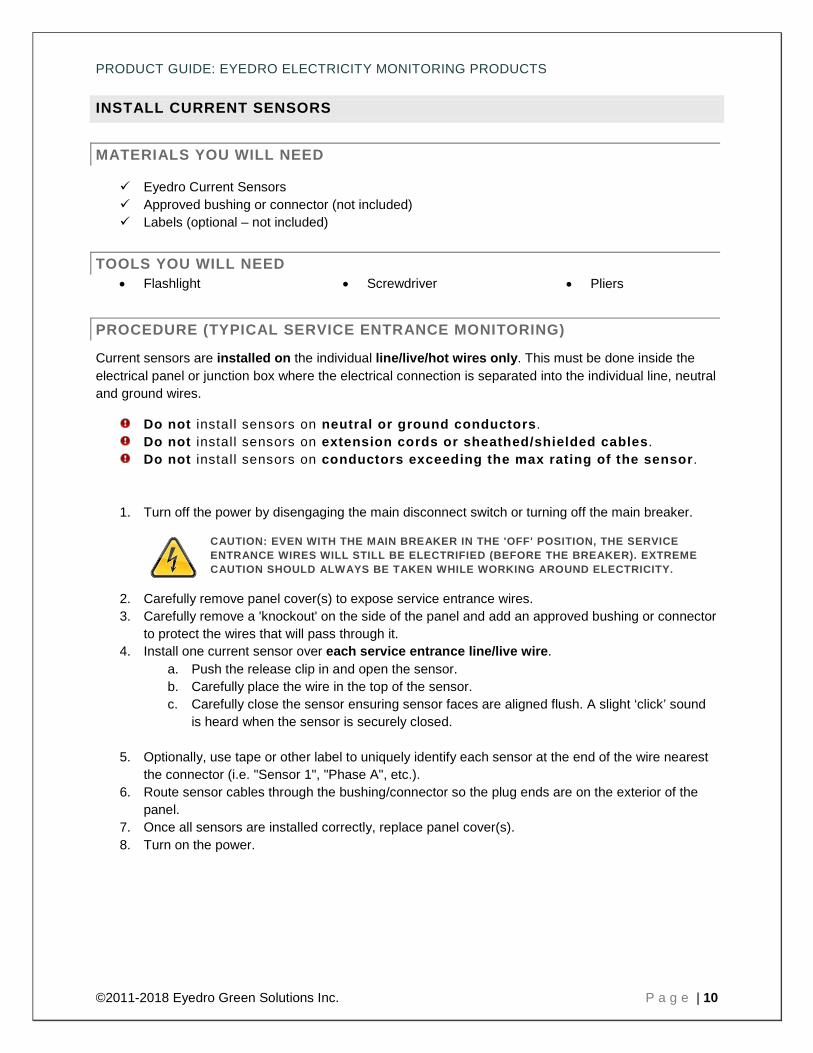
PROCEDURE (TYPICAL SERVICE ENTRANCE MONITORING)
Current sensors are installed on the individual line/live/hot wires only. This must be done inside the electrical panel or junction box where the electrical connection is separated into the individual line, neutral and ground wires.
Do not install sensors on neutral or ground conductors. Do not install sensors on extension cords or sheathed/shielded cables. Do not install sensors on conductors exceeding the max rating of the sensor.
1. Turn off the power by disengaging the main disconnect switch or turning off the main breaker.
CAUTION: EVEN WITH THE MAIN BREAKER IN THE 'OFF' POSITION, THE SERVICE ENTRANCE WIRES WILL STILL BE ELECTRIFIED (BEFORE THE BREAKER). EXTREME CAUTION SHOULD ALWAYS BE TAKEN WHILE WORKING AROUND ELECTRICITY.
2. Carefully remove panel cover(s) to expose service entrance wires. 3. Carefully remove a 'knockout' on the side of the panel and add an approved bushing or connector
to protect the wires that will pass through it. 4. Install one current sensor over each service entrance line/live wire.
a. Push the release clip in and open the sensor. b. Carefully place the wire in the top of the sensor. c. Carefully close the sensor ensuring sensor faces are aligned flush. A slight ‘click’ sound
is heard when the sensor is securely closed.
5. Optionally, use tape or other label to uniquely identify each sensor at the end of the wire nearest the connector (i.e. "Sensor 1", "Phase A", etc.).
6. Route sensor cables through the bushing/connector so the plug ends are on the exterior of the panel.
7. Once all sensors are installed correctly, replace panel cover(s). 8. Turn on the power.
PRODUCT GUIDE: EYEDRO ELECTRICITY MONITORING PRODUCTS
©2011-2018 Eyedro Green Solutions Inc. P a g e | 11
PROCEDURE (ALTERNATE APPLICATIONS)
The most common application of Eyedro Electricity Monitoring products is for monitoring of the electrical service entrance of a building. However, there are other common applications where Eyedro Electricity Monitoring products are often used. The following sub-sections provide brief overview of some of the most common applications.
To use Eyedro Electricity Monitoring products in one of these applications, follow ALL instructions and precautions from the Service Entrance installation procedure but substitute step 4 to install the sensors on the line/live conductor of your desired circuit.
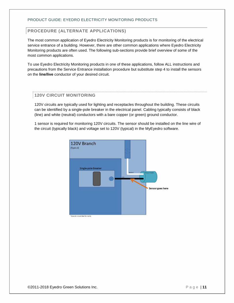
120V CIRCUIT MONITORING
120V circuits are typically used for lighting and receptacles throughout the building. These circuits can be identified by a single-pole breaker in the electrical panel. Cabling typically consists of black (line) and white (neutral) conductors with a bare copper (or green) ground conductor.
1 sensor is required for monitoring 120V circuits. The sensor should be installed on the line wire of the circuit (typically black) and voltage set to 120V (typical) in the MyEyedro software.
PRODUCT GUIDE: EYEDRO ELECTRICITY MONITORING PRODUCTS
©2011-2018 Eyedro Green Solutions Inc. P a g e | 12
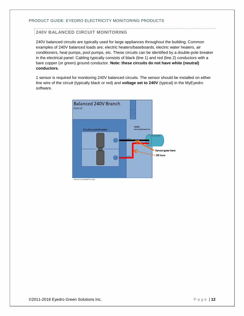
240V BALANCED CIRCUIT MONITORING
240V balanced circuits are typically used for large appliances throughout the building. Common examples of 240V balanced loads are; electric heaters/baseboards, electric water heaters, air conditioners, heat pumps, pool pumps, etc. These circuits can be identified by a double-pole breaker in the electrical panel. Cabling typically consists of black (line 1) and red (line 2) conductors with a bare copper (or green) ground conductor. Note: these circuits do not have white (neutral) conductors.
1 sensor is required for monitoring 240V balanced circuits. The sensor should be installed on either line wire of the circuit (typically black or red) and voltage set to 240V (typical) in the MyEyedro software.
PRODUCT GUIDE: EYEDRO ELECTRICITY MONITORING PRODUCTS
©2011-2018 Eyedro Green Solutions Inc. P a g e | 13
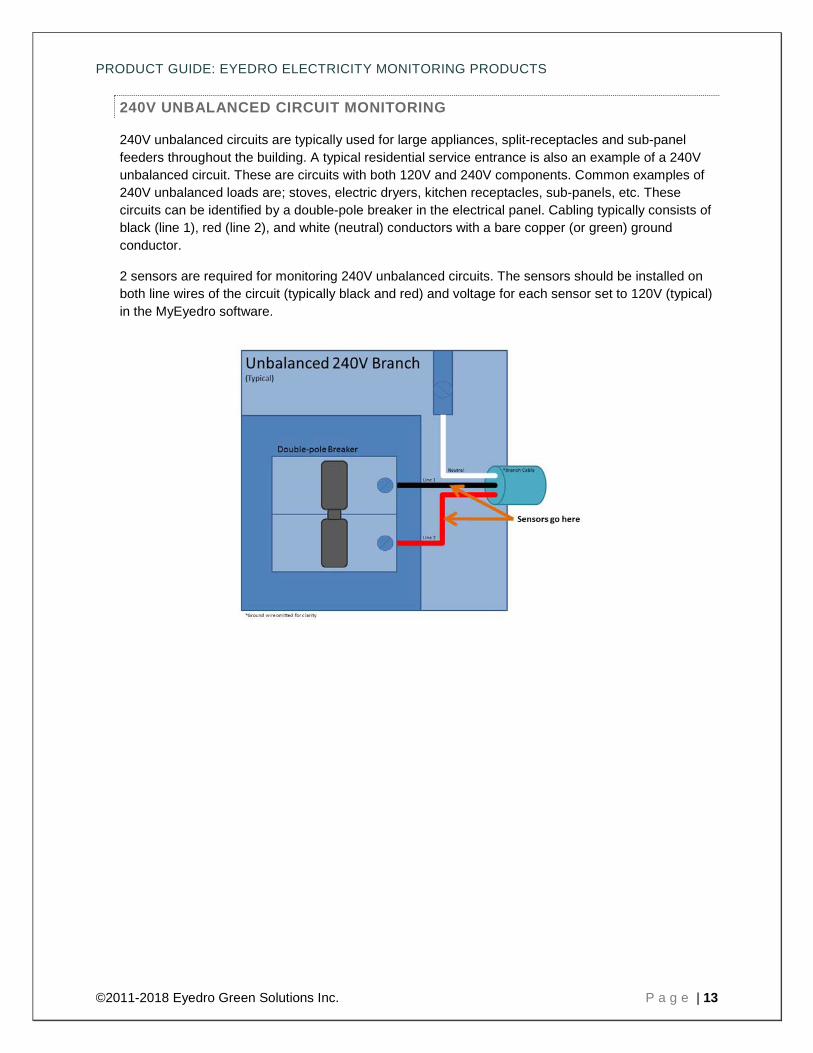
240V UNBALANCED CIRCUIT MONITORING
240V unbalanced circuits are typically used for large appliances, split-receptacles and sub-panel feeders throughout the building. A typical residential service entrance is also an example of a 240V unbalanced circuit. These are circuits with both 120V and 240V components. Common examples of 240V unbalanced loads are; stoves, electric dryers, kitchen receptacles, sub-panels, etc. These circuits can be identified by a double-pole breaker in the electrical panel. Cabling typically consists of black (line 1), red (line 2), and white (neutral) conductors with a bare copper (or green) ground conductor.
2 sensors are required for monitoring 240V unbalanced circuits. The sensors should be installed on both line wires of the circuit (typically black and red) and voltage for each sensor set to 120V (typical) in the MyEyedro software.
PRODUCT GUIDE: EYEDRO ELECTRICITY MONITORING PRODUCTS
©2011-2018 Eyedro Green Solutions Inc. P a g e | 14
THREE-PHASE SERVICE OR BRANCH MONITORING (DELTA OR WYE)
Three-phase installations are common in commercial and industrial environments. These installations require the use of Eyedro Business (EB*) products.
PRODUCT GUIDE: EYEDRO ELECTRICITY MONITORING PRODUCTS
©2011-2018 Eyedro Green Solutions Inc. P a g e | 15
MEASURE LINE VOLTAGE (OPTIONAL)
MATERIALS YOU WILL NEED
None
TOOLS YOU WILL NEED
• Voltmeter or Multimeter
PROCEDURE (TYPICAL RESIDENTIAL INSTALLATION)
CAUTION: Extreme caution should always be taken while working around electricity. Do not attempt this measurement without the proper tools and safeguards.
1. Locate an electrical receptacle as close to the current sensors as possible.
There is often a receptacle in the same room as the electrical panel.
2. Set the multimeter to AC voltage. The markings may appear as VAC, AC V, or a V beneath a sine wave.
3. Choose the AC voltage range closest to the voltage you will measure. Typical voltage in North American homes and businesses is between 110 to 120 volts.
Some circuits used for large equipment such as dryers, air conditioners, electric stoves and ovens may use voltage in the range of 220 to 240 volts. These instructions do not cover the methods used to measure a 220V outlet or three phase circuits.
4. Place one probe into each of the two slot terminals of the electrical receptacle. The voltage will be displayed on the meter.
Grasp the meter probes by the insulation - NEVER touch the metal probes during testing.
5. The voltage should typically measure in the range of 106 to 126 volts for most circuits. Record this value for later use while configuring your device in the software service.
6. Carefully remove the probes, being careful not to touch the metal part of the probes to anything or each other.

PRODUCT GUIDE: EYEDRO ELECTRICITY MONITORING PRODUCTS
©2011-2018 Eyedro Green Solutions Inc. P a g e | 16
ALIGN WIRELESS MODULES (E*W* PRODUCTS ONLY)
Eyedro Wireless Electricity Monitoring (E*W*) products have all the same features as the non-wireless version but do not require a network connection near the point where the sensors are installed. The modules will communicate with each other over their own private wireless network so that the sensors can be installed where you need them and the gateway module can be located near an available RJ45 network connection
E*W* products operate on a custom wireless protocol operating on the 2.4GHz frequency band. Operating range varies for each installation depending on distance between and the number (and material) of obstructions the wireless communication must pass through. Typical distances of 1000ft (300m) can be expected.
To achieve best performance in wireless installations the following guidelines should be followed:
1. Minimize the number of obstructions between modules where possible (interior/exterior walls, floors, windows, trees, etc). Line of sight provides best performance.
2. Minimize the number of 2.4GHz radiators in close proximity to the modules (WiFi routers, WiFi devices, Bluetooth devices, microwaves, ZigBee/IEEE 802.15.4 wireless devices).
3. If using a WiFi bridge device for connectivity, create a physical separation (>24”) between Eyedro module(s) and WiFi bridge. If possible, plug the two devices into separate receptacles.
4. Modules should be secured in position with screws, velcro tape or by other means. They should not be left hanging off of wires because if they are bumped it can affect the signal quality.
5. Keep the area around the Eyedro module free from metallic objects.
6. Do not lay the Eyedro module on the metal electrical panel - if unavoidable, put an insulating material, like wood or foam, between the Eyedro module and the metal.
7. Do not seal in the panel or other metal enclosure.
8. Try to ensure that the modules are positioned in the best possible orientation as shown in the picture below.
PRODUCT GUIDE: EYEDRO ELECTRICITY MONITORING PRODUCTS
©2011-2018 Eyedro Green Solutions Inc. P a g e | 17
MOUNT EYEDRO DEVICE(S)
MATERIALS YOU WILL NEED
Two(2) #6 mounting screws (optional – not included) Double-sided tape (optional – not included)
TOOLS YOU WILL NEED
• Screwdriver
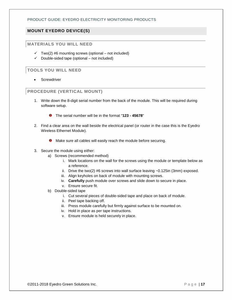
PROCEDURE (VERTICAL MOUNT)
1. Write down the 8-digit serial number from the back of the module. This will be required during software setup.
The serial number will be in the format "123 - 45678"
2. Find a clear area on the wall beside the electrical panel (or router in the case this is the Eyedro Wireless Ethernet Module).
Make sure all cables will easily reach the module before securing.
3. Secure the module using either: a) Screws (recommended method)
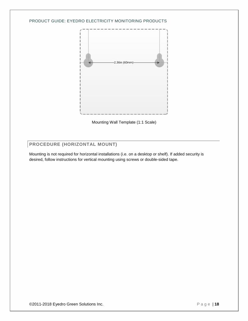
i. Mark locations on the wall for the screws using the module or template below as a reference.
ii. Drive the two(2) #6 screws into wall surface leaving ~0.125in (3mm) exposed. iii. Align keyholes on back of module with mounting screws. iv. Carefully push module over screws and slide down to secure in place. v. Ensure secure fit.
b) Double-sided tape i. Cut several pieces of double-sided tape and place on back of module. ii. Peel tape backing off. iii. Press module carefully but firmly against surface to be mounted on. iv. Hold in place as per tape instructions. v. Ensure module is held securely in place.
PRODUCT GUIDE: EYEDRO ELECTRICITY MONITORING PRODUCTS
©2011-2018 Eyedro Green Solutions Inc. P a g e | 18
Mounting Wall Template (1:1 Scale)
PROCEDURE (HORIZONTAL MOUNT)
Mounting is not required for horizontal installations (i.e. on a desktop or shelf). If added security is desired, follow instructions for vertical mounting using screws or double-sided tape.
PRODUCT GUIDE: EYEDRO ELECTRICITY MONITORING PRODUCTS
©2011-2018 Eyedro Green Solutions Inc. P a g e | 19
CONNECT CABLING
MATERIALS YOU WILL NEED
Ethernet cable Low-voltage power adapter(s) Tie wraps (optional – not included)
TOOLS YOU WILL NEED
• None
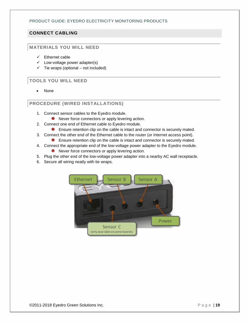
PROCEDURE (WIRED INSTALLATIONS)
1. Connect sensor cables to the Eyedro module. Never force connectors or apply levering action.
2. Connect one end of Ethernet cable to Eyedro module. Ensure retention clip on the cable is intact and connector is securely mated.
3. Connect the other end of the Ethernet cable to the router (or Internet access point). Ensure retention clip on the cable is intact and connector is securely mated.
4. Connect the appropriate end of the low-voltage power adapter to the Eyedro module. Never force connectors or apply levering action.
5. Plug the other end of the low-voltage power adapter into a nearby AC wall receptacle. 6. Secure all wiring neatly with tie wraps.
PRODUCT GUIDE: EYEDRO ELECTRICITY MONITORING PRODUCTS
©2011-2018 Eyedro Green Solutions Inc. P a g e | 20
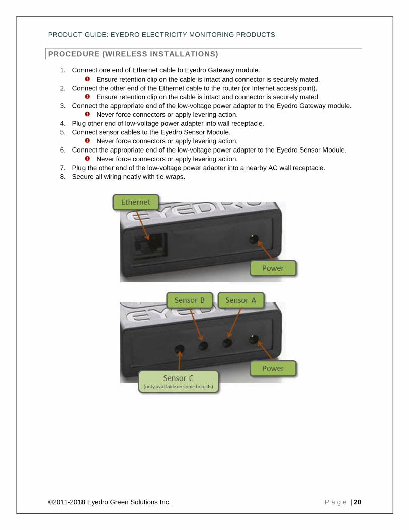
PROCEDURE (WIRELESS INSTALLATIONS)
1. Connect one end of Ethernet cable to Eyedro Gateway module. Ensure retention clip on the cable is intact and connector is securely mated.
2. Connect the other end of the Ethernet cable to the router (or Internet access point). Ensure retention clip on the cable is intact and connector is securely mated.
3. Connect the appropriate end of the low-voltage power adapter to the Eyedro Gateway module. Never force connectors or apply levering action.
4. Plug other end of low-voltage power adapter into wall receptacle. 5. Connect sensor cables to the Eyedro Sensor Module.
Never force connectors or apply levering action. 6. Connect the appropriate end of the low-voltage power adapter to the Eyedro Sensor Module.
Never force connectors or apply levering action. 7. Plug the other end of the low-voltage power adapter into a nearby AC wall receptacle. 8. Secure all wiring neatly with tie wraps.

PRODUCT GUIDE: EYEDRO ELECTRICITY MONITORING PRODUCTS
©2011-2018 Eyedro Green Solutions Inc. P a g e | 21
INTERNET CONNECTION
All Eyedro products are designed to take advantage of the MyEyedro cloud services – thus requiring the product(s) to be connected to the internet at all times. There is a small amount of internal memory to store data in the event of a temporary disruption to your internet service.
For most networks, it only requires that you plug the system into an active Ethernet port with a DHCP server somewhere on your network. A DHCP server is enabled on most routers by default and will provide connected hardware with an IP address so they can communicate via the internet.
In some cases, additional security has been added to the local network (firewall, port filtering, etc) making some additional configuration necessary. A good test would be to plug a laptop or computer into the same Ethernet port that you intend to use for your Eyedro product – if you can open a browser and navigate the web no additional configuration is likely needed.
A couple of important notes:
• Eyedro devices require connection to an active Ethernet port on your router, switch or hub. • Eyedro devices require a DHCP server somewhere on the network. • If your network does not have a DHCP server, or it is restricted, you may need to reserve an IP
address for the device based on the MAC address of the device. • The MAC address of your device will be 60:54:64:XX:YY:ZZ – where XX:YY:ZZ are the last
digits of your module serial number. For example, a module with the serial number 003-12345 will have the MAC address 60:54:64:31:23:45.
• Eyedro devices communicate using port 80 (HTTP) – all communication to/from the device looks like standard web traffic.
• Eyedro devices do not have an ICMP server on them and thus, will not respond to ping requests. • Eyedro devices ship with Ethernet patch cords (straight-through). Most routers, switches and
hubs provide crossover functionality but some old hardware may not. In those cases, it may be necessary to connect to a specific port or use a crossover cable.
• Eyedro devices communicate via Half-Duplex 10Base-T. Most routers, switches and hubs provide coexistence but some may not. In those cases, it may be necessary to configure the connected port appropriately.
• The wireless Eyedro products do not communicate using the WiFi protocol. They use a custom wireless protocol between modules and the gateway unit plugs into a physical Ethernet port, on your router or switch, to access the internet.
PRODUCT GUIDE: EYEDRO ELECTRICITY MONITORING PRODUCTS
©2011-2018 Eyedro Green Solutions Inc. P a g e | 22
SOFTWARE CONFIGURATION
MYEYEDRO.COM
The MyEyedro electricity monitoring cloud service is the interface for your Eyedro device(s). Eyedro and MyEyedro are always working together to measure, analyze and store your electricity usage and cost information. With MyEyedro, your electricity data is automatically and securely stored in the cloud, so it’s ready when and where you need it most. MyEyedro presents your electricity data in ways that are engaging, informative and easy to understand. See real-time electricity usage and gain access to many helpful features, including:
• Responsive real-time graphs
• Hourly/Daily/Weekly/Monthly cost estimates
• Bill comparisons and estimates
• Downloadable data for further analysis
MyEyedro is easy to use and accessible from a standard web browser.
1. Go online to: http://my.eyedro.com to create your online account (or login if you have an existing account).
2. From the system configuration screen, enter the serial number of your Eyedro Module(s) – found on the back of the device(s).
For more information on MyEyedro and complete instructions for adding devices, refer to the online documentation and user guide found at http://eyedro.com/support
PRODUCT GUIDE: EYEDRO ELECTRICITY MONITORING PRODUCTS
©2011-2018 Eyedro Green Solutions Inc. P a g e | 23
SPECIFICATIONS
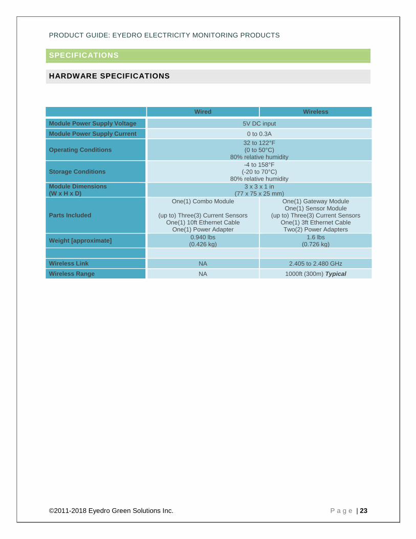
HARDWARE SPECIFICATIONS
Wired Wireless
Module Power Supply Voltage 5V DC input Module Power Supply Current 0 to 0.3A
Operating Conditions 32 to 122°F (0 to 50°C)
80% relative humidity
Storage Conditions -4 to 158°F
(-20 to 70°C) 80% relative humidity
Module Dimensions (W x H x D)
3 x 3 x 1 in (77 x 75 x 25 mm)
Parts Included
One(1) Combo Module
(up to) Three(3) Current Sensors One(1) 10ft Ethernet Cable
One(1) Power Adapter
One(1) Gateway Module One(1) Sensor Module
(up to) Three(3) Current Sensors One(1) 3ft Ethernet Cable Two(2) Power Adapters
Weight [approximate] 0.940 lbs (0.426 kg)
1.6 lbs (0.726 kg)
Wireless Link NA 2.405 to 2.480 GHz Wireless Range NA 1000ft (300m) Typical

PRODUCT GUIDE: EYEDRO ELECTRICITY MONITORING PRODUCTS
©2011-2018 Eyedro Green Solutions Inc. P a g e | 24
SENSOR SPECIFICATIONS
Sensor Input Output Accuracy Opening Cable Length
200A Current (max 600V – EH*)
0 to 200A AC 50-60Hz
0 to 7.5V AC ±1% Typical1 ±1% Typical1 1.000 in
(25.40 mm)
79 in (2000 mm)
The following are only available as substitutions for Eyedro Business (EB*) products
400A Current (max 600V – EB*)
0 to 400A AC 50-60Hz
0 to 7.5V AC
±1% Typical1
1.25 x 1.25 in (32 x 32 mm)
96 in (2400 mm)
600A Current (max 600V – EB*)
0 to 600A AC 50-60Hz
800A Current (max 600V – EB*)
0 to 800A AC 50-60Hz
2.0 x 2.0 in (51 x 51 mm)
1200A Current (max 600V – EB*)
0 to 1200A AC
50-60Hz
2000A Current (max 600V – EB*)
0 to 2000A AC
50-60Hz 0 to 5.0V AC 3.0 x 5.0 in (76 x 127 mm)
3000A Current (max 600V – EB*)
0 to 3000A AC
50-60Hz
1Accuracy noted is for sensor readings at 10% to 90% of rated current. Instantaneous power and power consumption measurements combine sensor measurements with a constant voltage value (defined by user – defaults to 120V). This product also requires a continuous internet connection.
PRODUCT GUIDE: EYEDRO ELECTRICITY MONITORING PRODUCTS
©2011-2018 Eyedro Green Solutions Inc. P a g e | 25
COMPLIANCE
This product has been tested and found in compliance to:
Safety Requirements for Electrical Equipment for Measurement, Control, and Laboratory Use – Part 1: General Requirements UL 61010-1 Second Edition, Dated July 12, 2004 (Updated October 28, 2008); Safety Requirements for Electrical Equipment for Measurement, Control, and Laboratory Use – Part 1: General Requirements CAN/CSA-C22.2 No. 61010-1 Second Edition (IEC 61010-1:2001, Mod), Dated July 12, 2004 (Updated October 28, 2008);
Industry Canada ICES=003, Issue 4 – Interference-Causing Equipment Standard – Digital Apparatus;
EN 61326-1:2006 – Electrical Equipment for Measurement, Control and Laboratory Use – EMC Requirements, Part 1: General Requirements;
European CISPR 11:2009 +A1:2010 / EN 55011:2009 +A1:2010, Class A, Group 1 – Industrial, Scientific and Medical (ISM) Equipment;
Federal Communications Commission (FCC) CFR 47, Part 15, Subpart B - Class A Unintentional Radiators.
This device complies with Part 15 of the FCC Rules. Operation is subject to the following two conditions: (1) this device may not cause harmful interference and (2) this device must accept any interference received, including interference that may cause undesired operation.
PRODUCT GUIDE: EYEDRO ELECTRICITY MONITORING PRODUCTS
©2011-2018 Eyedro Green Solutions Inc. P a g e | 26
WARRANTY
LIMITED ONE YEAR WARRANTY
Eyedro Green Solutions Inc. warrants this product for a period of one year from date of purchase for all defects in material and workmanship. Defective parts may be repaired or replaced, at the discretion of the manufacturer, free of charge during this period.
Warranty Conditions:
1. The product must be installed and operated in strict accordance to the provided instructions. 2. Warranty requires the original proof of purchase. 3. Warranty is void if the product has been tampered with or modified in any way. 4. Warranty returns require a Return Material Authorization (RMA) number. Visit
eyedro.com/support for an RMA number.

PRODUCT GUIDE: EYEDRO ELECTRICITY MONITORING PRODUCTS
©2011-2018 Eyedro Green Solutions Inc. P a g e | 27
CONTACT INFORMATION
If you have any questions about using your Eyedro Electricity Monitoring System please visit our website for documentation, videos, frequently asked questions and contact forms.
Website: eyedro.com
Support: eyedro.com/support
Eyedro Green Solutions Inc. 151 Charles Street W, Suite 100
Kitchener, ON N2G 1H6
COPYRIGHT © 2011-2018 EYEDRO GREEN SOLUTIONS INC. ALL RIGHTS RESERVED. THIS DOCUMENT, AND ALL ITS CONTENTS, MAY NOT BE MODIFIED, DISTRIBUTED, COPIED, OR REPRODUCED IN ANY FORM, IN PART OR IN WHOLE, WITHOUT THE EXPRESS WRITTEN CONSENT OF EYEDRO GREEN SOLUTIONS INC. THE EYEDRO ELECTRICITY MONITORING SYSTEM IS INTENDED TO BE USED TO INCREASE AWARENESS OF ELECTRICITY CONSUMPTION WITHIN THE BUILDING AND AS AN ADDITIONAL RESOURCE TO APPROXIMATE UTILITY COSTS. SYSTEM ACCURACY DEPENDS ON A NUMBER OF FACTORS INCLUDING (BUT NOT LIMITED TO): MEASUREMENT AMPLITUDE, SENSOR CALIBRATION, UP TIME, AND STABILITY OF THE VOLTAGE SUPPLY. IT IS NOT INTENDED TO REPLACE THE ELECTRICITY METER FOR THE BUILDING. EYEDRO GREEN SOLUTIONS INC. RESERVES THE RIGHT TO MAKE CHANGES TO THE PRODUCTS, SPECIFICATIONS, AND/OR DOCUMENTATION AT ANY TIME WITHOUT NOTICE. IMAGES AND/OR INSTRUCTIONS DETAILED IN THIS DOCUMENT MAY DIFFER FROM THE ACTUAL PRODUCT HARDWARE AND/OR SOFTWARE.
PRODUCT GUIDE: EYEDRO ELECTRICITY MONITORING PRODUCTS
©2011-2018 Eyedro Green Solutions Inc. P a g e | 28
APPENDIX A: TROUBLESHOOTING
Device installation is simple and non-invasive but occasionally problems do arise. The following provide troubleshooting tips for the most common issues encountered during (or after) installation. Before contacting support, please refer to this troubleshooting section to see if it provides a solution - support personnel will likely be directing you to its contents.

PRODUCT GUIDE: EYEDRO ELECTRICITY MONITORING PRODUCTS
©2011-2018 Eyedro Green Solutions Inc. P a g e | 29
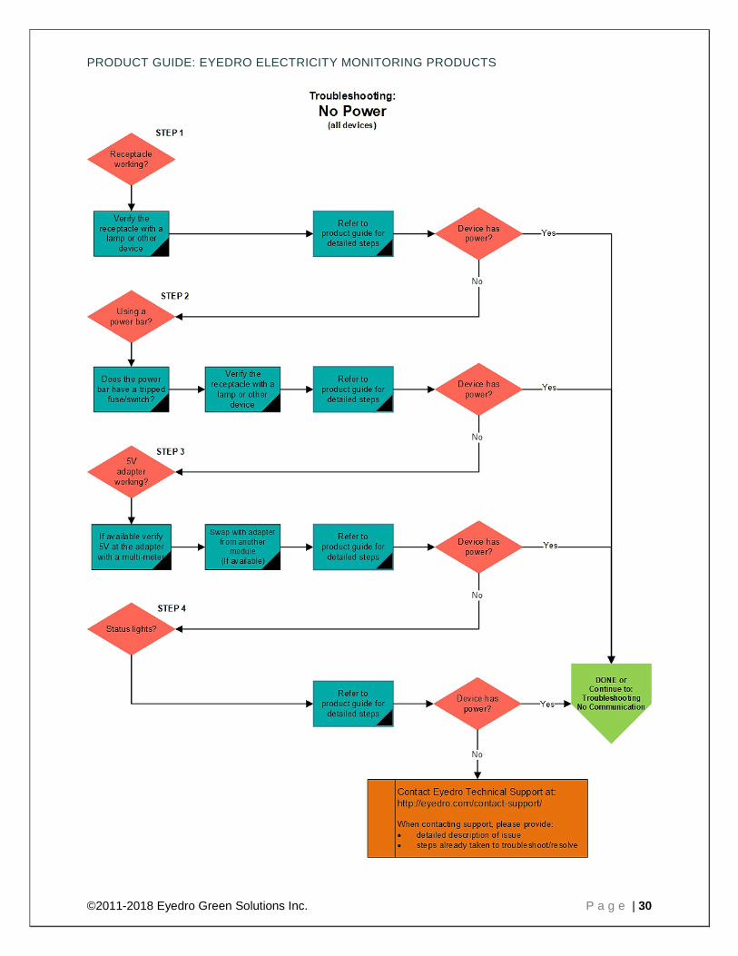
NO POWER (ALL DEVICES)
IS THE RECEPTACLE ENERGIZED? • If you have a multi-meter or receptacle tester, verify receptacle. • If not, check the following:
o Try plugging the Eyedro device directly into the wall (bypassing the power bar). o Is your receptacle on the same circuit as a wall switch that cuts the power to the
receptacle? Try plugging power bar into a different receptacle. o Is the receptacle on a timer or smart receptacle device that cuts the power? Try plugging
power bar into a different receptacle directly into the wall (bypassing any smart devices). o Is the fuse/breaker tripped/off? Ensure fuse/breaker hasn’t been tripped at the panel. o Have you tried a different receptacle? Try plugging a lamp or other appliance into the
receptacle and verify operation. o Do other devices work in the same receptacle?
IS THE DEVICE PLUGGED INTO A POWER BAR? • If you have a multi-meter or receptacle tester, verify receptacle. • If not, ensure the following:
o Is the power bar on a timer or smart receptacle device that cuts the power? Try plugging into a different receptacle.
o Is the power bar on? If applicable, ensure the power switch is on. o Does the power bar have a tripped fuse/breaker? If applicable, ensure the reset
button/switch is in the correct position. o Do other devices work in the same power bar receptacle? Try plugging a lamp or other
appliance into the receptacle and verify operation. o Have you tried a different receptacle on the power bar?
IS THE 5V ADAPTER OPERATING? • If you have a multi-meter, verify 5V output from the power adapter. Shield=Ground, Pin=5V • If you have a wireless system, try using the 5V adapter from the other device. • If you are going to try a power adapter from another appliance, ensure it matches the output
specification of the one provided with your Eyedro system: o Voltage: 5VDC o Current: 0.5A o Connector: 1.65mm DC barrel o Polarity: Center pin positive (shield=GND/0V, pin=5V)
CAN YOU SEE THE STATUS LIGHTS? • Looking through the ports (sensor or Ethernet) on the device faceplate should reveal status lights.
Lights on (in any state) indicate that there is power to the device - Note the status lights and skip to the appropriate internet and/or wireless communication troubleshooting section(s).
• LED Status (EH*EM and EB*EM systems): o GREEN/OFF flashing (~1sec) indicates correct operation o Solid GREEN indicates internet connection issue o Solid RED indicates wireless connection issue o RED/OFF flashing (~0.5sec) indicates system error
PRODUCT GUIDE: EYEDRO ELECTRICITY MONITORING PRODUCTS
©2011-2018 Eyedro Green Solutions Inc. P a g e | 30

PRODUCT GUIDE: EYEDRO ELECTRICITY MONITORING PRODUCTS
©2011-2018 Eyedro Green Solutions Inc. P a g e | 31
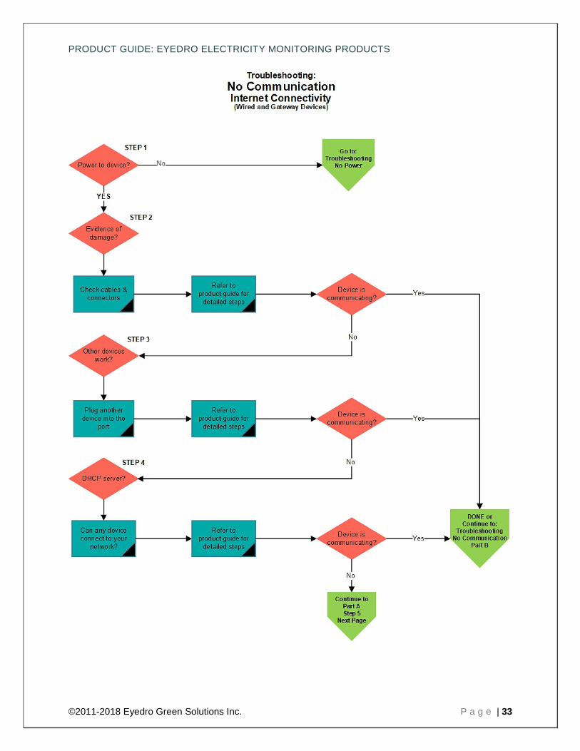
NO COMMUNICATION – PART A VERIFY INTERNET CONNECTIVITY (WIRED AND GATEWAY DEVICES)
HAVE YOU VERIFIED DEVICE HAS POWER? • Follow troubleshooting tips to verify power.
IS THERE EVIDENCE OF PHYSICAL DAMAGE? • Is there evidence of physical damage to the port on your Eyedro device (bent/missing pins,
corrosion, or debris)? • Is there evidence of physical damage to the port on your router/switch/modem (bent/missing pins,
corrosion, or debris)? • Is there evidence of physical damage to the Ethernet cable (bent/missing pins, corrosion, debris,
frayed or damaged wires/cable jacket or broken/missing retention clips)? • Ensure the cable is properly secured at both ends and retention clips are not missing. • Try connecting to a different port on your router/switch/modem. • If possible, try connecting with a different Ethernet cable.
DOES THE PORT ON YOUR ROUTER/SWITCH/MODEM WORK WITH OTHER DEVICES?
• Have you tried plugging another device (i.e. laptop) into the same port? Try to use the same Ethernet cable when testing other devices to remove variables.
• Is the port intended for specific functions or hardware (VOIP, etc)? Try a different port • Does the port accept traffic from 10Base-T Half-Duplex devices? Old network devices may not
support co-existence or require toggle switches or software configuration set appropriately. • Verify your router and/or modem is running the most recent firmware versions.
IS THERE A DHCP SERVER ON YOUR NETWORK? • Can anyone come in and connect a device into your network or do you need to take specific
steps to allow them access?
IS THERE A FIREWALL BLOCKING TRAFFIC? • Eyedro devices communicate using port 80 (HTTP). All communication to/from the device looks
like standard web traffic. • Eyedro servers sit behind load balancers and do not use static IP addresses. Any allowance
should be made based on domain and not specific IP addresses. • Have you tried disabling (temporarily) to see if it resolves the issue? • If applicable, have you tried connecting to a DMZ port (bypassing firewalls) to see if it resolves
the issue?
HAVE YOU TRIED MINIMIZING THE NUMBER OF NETWORK DEVICES BETWEEN YOUR EYEDRO AND INTERNET CONNECTION?
• For complex networks with many devices between, try connecting further downstream in your
PRODUCT GUIDE: EYEDRO ELECTRICITY MONITORING PRODUCTS
©2011-2018 Eyedro Green Solutions Inc. P a g e | 32
network (as close to the internet access point as possible) to see if it resolves the issue.
ARE YOU USING A WIFI BRIDGE DEVICE? • Try plugging the device into a known working port directly on your switch/router/modem. • Try plugging the WiFi bridge into a different receptacle or power bar than the one used to power
your Eyedro device. • Does your WiFi bridge accept input from a 10Base-T Half-Duplex device?
NOTE: Eyedro devices do not have an ICMP server on them and thus, will NOT respond to ping requests
NOTE: Eyedro devices can be configured to operate using static network parameters. To do this, you will need to contact support and provide the desired IP Address, Gateway, Netmask, DNS1 and DNS2 settings. Your device will need to be active and temporarily connected to the internet for configuration to be successfully sent to your device.
PRODUCT GUIDE: EYEDRO ELECTRICITY MONITORING PRODUCTS
©2011-2018 Eyedro Green Solutions Inc. P a g e | 33

PRODUCT GUIDE: EYEDRO ELECTRICITY MONITORING PRODUCTS
©2011-2018 Eyedro Green Solutions Inc. P a g e | 34
PRODUCT GUIDE: EYEDRO ELECTRICITY MONITORING PRODUCTS
©2011-2018 Eyedro Green Solutions Inc. P a g e | 35
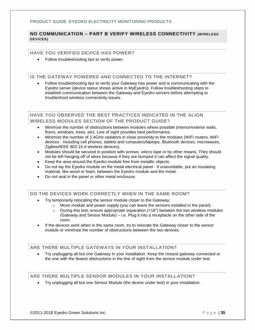
NO COMMUNICATION – PART B VERIFY WIRELESS CONNECTIVITY (WIRELESS DEVICES)
HAVE YOU VERIFIED DEVICE HAS POWER? • Follow troubleshooting tips to verify power.
IS THE GATEWAY POWERED AND CONNECTED TO THE INTERNET? • Follow troubleshooting tips to verify your Gateway has power and is communicating with the
Eyedro server (device status shows active in MyEyedro). Follow troubleshooting steps to establish communication between the Gateway and Eyedro servers before attempting to troubleshoot wireless connectivity issues.
HAVE YOU OBSERVED THE BEST PRACTICES INDICATED IN THE ALIGN WIRELESS MODULES SECTION OF THE PRODUCT GUIDE?
• Minimize the number of obstructions between modules where possible (interior/exterior walls, floors, windows, trees, etc). Line of sight provides best performance.
• Minimize the number of 2.4GHz radiators in close proximity to the modules (WiFi routers, WiFi devices - including cell phones, tablets and computers/laptops, Bluetooth devices, microwaves, ZigBee/IEEE 802.15.4 wireless devices).
• Modules should be secured in position with screws, velcro tape or by other means. They should not be left hanging off of wires because if they are bumped it can affect the signal quality.
• Keep the area around the Eyedro module free from metallic objects. • Do not lay the Eyedro module on the metal electrical panel - if unavoidable, put an insulating
material, like wood or foam, between the Eyedro module and the metal. • Do not seal in the panel or other metal enclosure.
DO THE DEVICES WORK CORRECTLY WHEN IN THE SAME ROOM? • Try temporarily relocating the sensor module closer to the Gateway;
o Move module and power supply (you can leave the sensors installed in the panel). o During this test, ensure appropriate separation (>18”) between the two wireless modules
(Gateway and Sensor Module) – i.e. Plug it into a receptacle on the other side of the room.
• If the devices work when in the same room, try to relocate the Gateway closer to the sensor module or minimize the number of obstructions between the two devices.
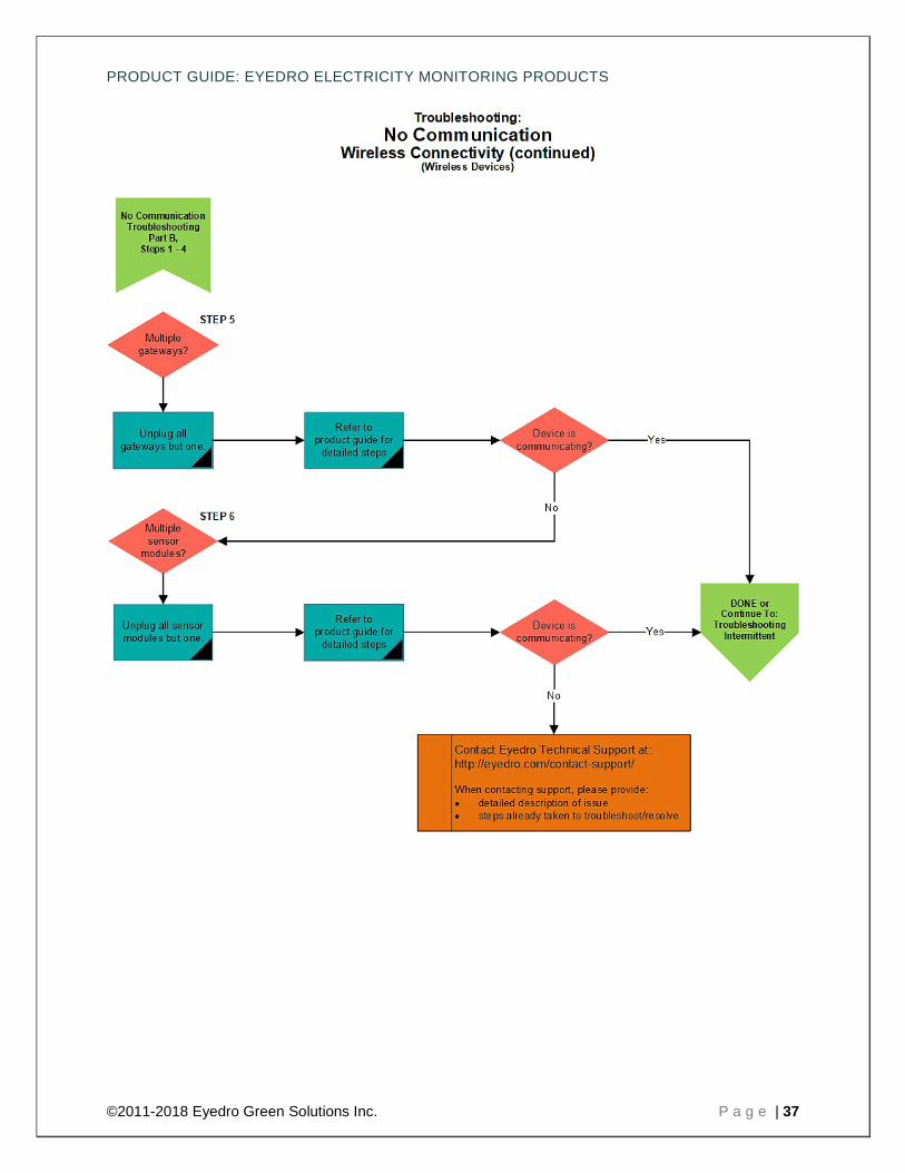
ARE THERE MULTIPLE GATEWAYS IN YOUR INSTALLATION? • Try unplugging all but one Gateway in your installation. Keep the closest gateway connected or
the one with the fewest obstructions in the line of sight from the sensor module under test.
ARE THERE MULTIPLE SENSOR MODULES IN YOUR INSTALLATION? • Try unplugging all but one Sensor Module (the device under test) in your installation.

PRODUCT GUIDE: EYEDRO ELECTRICITY MONITORING PRODUCTS
©2011-2018 Eyedro Green Solutions Inc. P a g e | 36
•
PRODUCT GUIDE: EYEDRO ELECTRICITY MONITORING PRODUCTS
©2011-2018 Eyedro Green Solutions Inc. P a g e | 37
PRODUCT GUIDE: EYEDRO ELECTRICITY MONITORING PRODUCTS
©2011-2018 Eyedro Green Solutions Inc. P a g e | 38
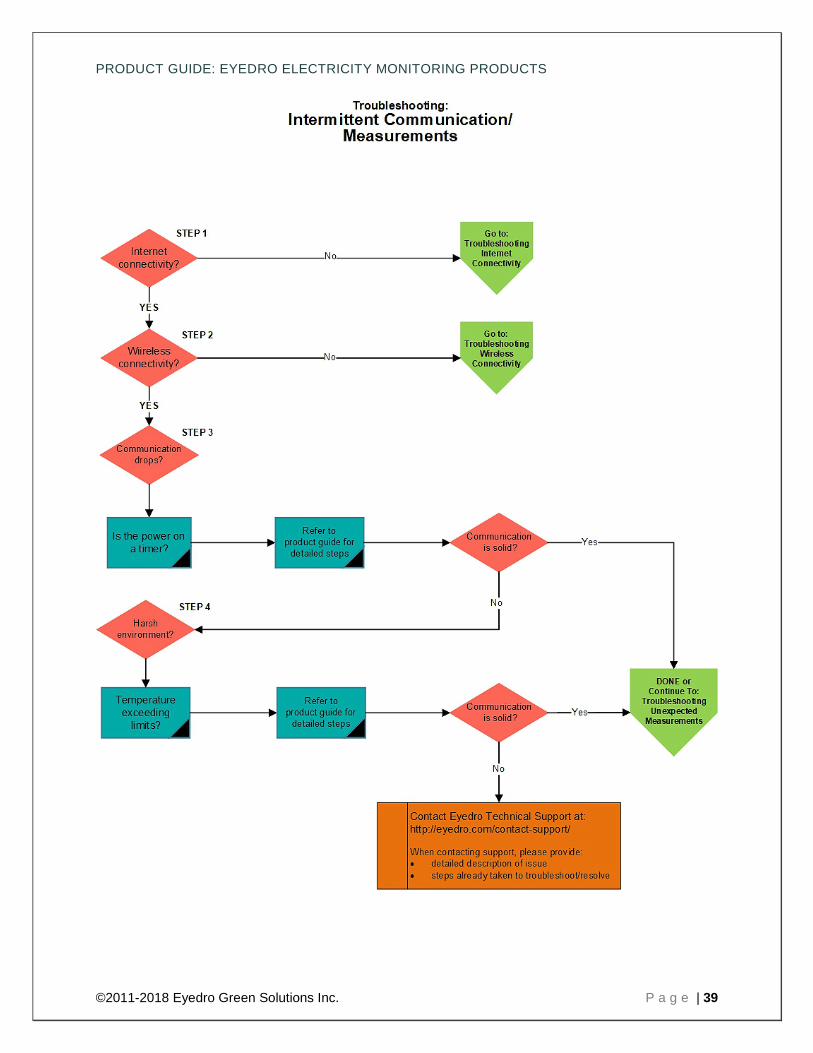
INTERMITTENT COMMUNICATION/MEASUREMENTS
HAVE YOU FOLLOWED THE INTERNET CONNECTIVITY TROUBLESHOOTING TIPS?
• Follow troubleshooting tips to verify internet connectivity.
HAVE YOU FOLLOWED THE WIRELESS CONNECTIVITY TROUBLESHOOTING TIPS?
• Follow troubleshooting tips to verify wireless connectivity.
DOES IT DROP OUT AT SPECIFIC TIMES OF THE DAY? • Is a receptacle or power bar being turned off that provides power to the unit? • Do you notice issues on any other internet connected devices? • Has a device joined your network and introduced an IP address conflict? • Is there a significant increase in the amount of on/off transactions in the building/branch/load
being monitored? Try switching to use polled (10-30 second) mode for detection. • Wireless devices:
o Is a door being opened/closed effecting the communication between wireless devices? o Is a 2.4GHz radiator being introduced? Do you come home and set your cellphone or
laptop up near the Eyedro device? Does another wireless device turn on (casting device, smart appliance, etc)?
IS YOUR DEVICE INSTALLED IN A HARSH ENVIRONMENT? • If modules are installed in direct sunlight, ensure the temperature is not exceeding maximum
operating temperature. • If modules are installed in unconditioned spaces (i.e. garages), ensure temperature is not
exceeding minimum or maximum operating temperatures.
PRODUCT GUIDE: EYEDRO ELECTRICITY MONITORING PRODUCTS
©2011-2018 Eyedro Green Solutions Inc. P a g e | 39

PRODUCT GUIDE: EYEDRO ELECTRICITY MONITORING PRODUCTS
©2011-2018 Eyedro Green Solutions Inc. P a g e | 40
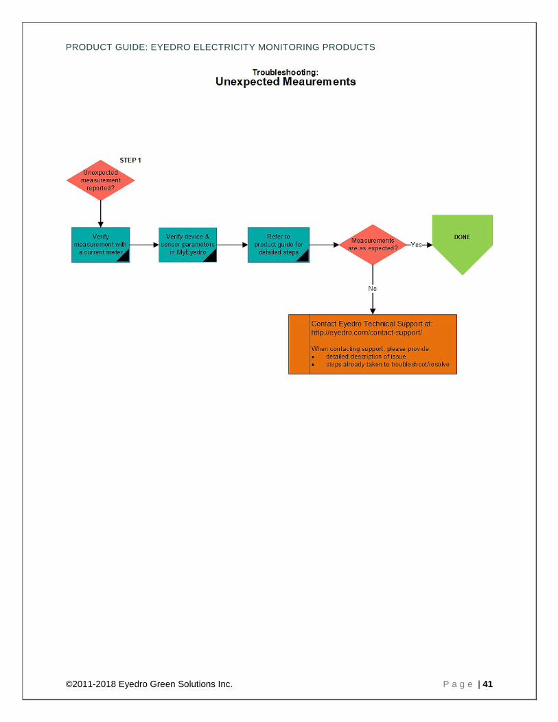
UNEXPECTED MEASUREMENTS
IS YOUR DEVICE REPORTING A MEASUREMENT YOU ARE NOT EXPECTING? • If available, verify expected measurement with a clamp on current meter.
• Verify device and sensor parameters in MyEyedro and adjust accordingly:
o Do you have the correct sensor type selected in MyEyedro? o Are your voltage and power factor settings correct in MyEyedro? Note that line voltage
and power factor may fluctuate over time. o Are your voltage configuration (delta or other) and multiplier settings correct MyEyedro? o Are you looking at the correct device? MyEyedro allows display groups to be built from
sensors spanning devices, make sure the display group you are looking at contains the sensors you expect.
• Does the expected reading exceed the maximum rating of the sensor? Use a higher rated sensor. • Is the sensor clamped around a single current carrying conductor (not an appliance cord or
extension cord)? o Sensor should be clamped around a line conductor (not neutral or ground). o Sensor should be clamped around a single conductor.
• Is the sensor closed completely? o Please ensure that your sensors are closed securely as this can affect your readings. o You will almost always hear an audible click when you snap the sensors shut. o If you don't hear the click there is a good chance that the sensor is not closed properly. o The current sensors can be snapped shut by gently pushing down and forwards
simultaneously. • Are there signs of physical damage to the sensor (ferrite, hinge, clip, cable or connector) or
Eyedro sensor port? • Is there a source of magnetic or RF interference?
o Try repositioning module and cabling (as far away as practical). o Try powering from a different receptacle (as far away as practical)
• Try connecting affected sensor to a different port. Did it follow the sensor or stay with the port?
PRODUCT GUIDE: EYEDRO ELECTRICITY MONITORING PRODUCTS
©2011-2018 Eyedro Green Solutions Inc. P a g e | 41