product submittal/substitution request - copperstate · re v. g installation instructions (solid...
TRANSCRIPT

TO:
PROJECT:
PROJECT LOCATION:
SPECIFIED ITEM:
Section Page Paragraph Description
P R O D U C T S U B M I T TA L / S U B S T I T U T I O N R E Q U E S T E D :
The attached submittal package includes the product description, specifications, drawings, and performance data for use in the evaluation of the request. S U B M I T T E D B Y:
Name: Signature:
Company:
Address:
:xaF:enohpeleT:etaD
F O R U S E B Y T H E A R C H I T E C T A N D / O R E N G I N E E R
Approved Approved as Noted Not Approved
(If not approved, please briefly explain why the product was not accepted.)
By:
Remarks:
Questions or inquiries? Contact us at [email protected], or call 1.800.524.3244
Date:
Product Submittal/Substitution Request
©2015 Powers Fasteners
1
Table of Contents
Powers Fasteners® Pure110+(tm) Submittal Section:
Competitive Comparisons:
- Powers Fasteners® Pure110+(tm) vs. Simpson* SET-XP®
Product Pages:
- Installation Instructions - Design Tables - Ordering Information
Code Reports & Agency Listings:
- ICC-ES Approval: ESR-3298 (Cracked & Uncracked Concrete)
Other Technical Information:
- Material Safety Data Sheet (MSDS)
Offline version available for download at www.powersdesignassist.com.
Powers Fasteners developed the Powers Design Assist (PDA) anchor software to enable usersto input technical data into a dynamic model environment-to visualize, consider, and specifyanchors in today's changing engineering climate.
For a demonstration of the latest version of PDA, contact us at www.powers.com or call (800)524-3244.
2

2300
4600
6900
9200
11500
13800
16100
18400
20700
23000
Pure110+™ vs. simPson* seT-XP®
Product ComparisonProduct Name Pure110+ SET-XP
Company Powers Fasteners Simpson*
Description Epoxy Anchoring System Adhesive Anchoring System
Size Range (inch) (3/8, 1/2, 5/8, 3/4, 7/8, 1, 1-1/4) #3, #4, #5, #6, #7, #8, #9, #10 (3/8, 1/2, 5/8, 3/4, 7/8, 1, 1-1/4) #3, #4, #5, #6, #7, #8, #10
ICC-ES (concrete) ESR-3298 ESR-2508
Revision Date 2015 Jan 2015 Jan
Cracked Concrete Yes Yes
Seismic Approval in Concrete Yes Yes
LEED Yes Yes
VOC Yes Yes
NSF 61 (potable drinking water) Yes Yes
*SET-XP and Simpson are registered trademarks of Simpson Strong-Tie Company Inc.
Competitive Comparison
Sour
ce: E
SR-3
298
(Rev
ised:
201
5 Ja
n), E
SR-2
322
(Rev
ised:
201
5 Ja
n)
1/24
Ø Anchor (inches)hef (inches)
2300
4600
6900
9200
11500
13800
16100
18400
20700
23000
LBS
LBS
1/26
5/85
5/87-1/2
3/46
3/49
7/87
7/810-1/2
18
112
1/24
Ø Anchor (inches)hef (inches)
1/26
5/85
5/87-1/2
3/46
3/49
7/87
7/810-1/2
18
112
Factored Tension Loads CrackedConcrete2500 psi NWC, Rod ASTM A193 Grade B7 Dry concrete, sustained loading and periodic special inspection
Pure110+ Bond Strength Values at 110˚F Long-term Temp, 162˚F Short-term Temp
SET-XP Bond Strength Values at 110˚F Long-term Temp, 150˚F Short-term Temp
Factored Shear Loads CrackedConcrete2500 psi NWC, Rod ASTM A193 Grade B7 Dry concrete, sustained loading and periodic special inspection
Pure110+ Bond Strength Values at 110˚F Long-term Temp, 162˚F Short-term Temp
SET-XP Bond Strength Values at 110˚F Long-term Temp, 150˚F Short-term Temp
POW2354_pure110_vs_setxp.indd 1 2/5/15 3:43 PM
3

www.powers.com 18
Ad
hesiv
es
InStallatIon InStruCtIonS (SolID BaSe materIalS)
TECH
MAN
UAL
– Ad
HEsi
vEs
©20
15 P
OW
ERs
vO
LUM
E 1
– R
Ev. g
inStaLLation inStructionS (SoLid baSe MateriaLS)Permissible iNstallatioN CoNditioNs
Dry Concrete: cured concrete that, at the time of adhesive anchor installation, has not been exposed to water for the preceding 14 days.Water-Saturated Concrete (wet): cured concrete that, at the time of adhesive anchor installation, has been exposed to water over a sufficient length of time to have the maximum possible amount of absorbed water into the concrete pore structure to a depth equal to the anchor embedment depth.Water-Filled Holes (flooded): cured concrete that is water-saturated and where the drilled hole contains standing water at the time of anchor installation.Underwater Concrete (submerged): cured concrete that is water-saturated and covered with water at the time of anchor installation.
drillinG
1- drill a hole into the base material with a rotary hammer drill tool to the size and embedment required by the selected steel anchor element (reference installation specifications for threaded rod and reinforcing bar). The tolerances of the carbide drill bit must meet ANsi standard B212.15.
• Precaution: Use suitable eye and skin protection. Avoid inhalation of dust during drilling and/or removal.
• Note! in case of standing water in the drilled hole (flooded hole condition), all the water has to be removed from the hole (e.g. vacuum, compressed air, etc.) prior to cleaning. For underwater (submerged) installations please see separated specific instructions below.
hole cleaninG dry or wet/water-saturated holes (Blow 2x, Brush 2x, Blow 2x)
2X
2a- starting from the bottom or back of the drilled anchor hole, blow the hole clean (free of noticeable dust) a minimum of two times (2x).
• Use a compressed air nozzle (min. 90 psi) for all sizes of anchor rod and reinforcing bar (rebar).
2X
2b- determine wire brush diameter (reference hole cleaning equipment selection table) for the drilled hole and attach the brush with adaptor to a rotary drill tool or battery screw gun. Brush the hole with the selected wire brush a minimum of two times (2x).
• A brush extension (supplied by Powers Fasteners) must be used for holes drilled deeper than the listed brush length. The wire brush diameter must be checked periodically during use. The brush should resist insertion into the drilled hole, if not the brush is too small and must be replaced with the proper brush diameter. (new brush)
2X
2c- Repeat step 2a- again by blowing the hole clean a minimum of two times (2x).
• When finished the hole should be clean and free of dust, debris, ice, grease, oil or other foreign material.
Next go to Step 3.
hole cleaninG underwater installation (Flush, Brush 2x, Flush)
2a- starting from the bottom or back of the drilled anchor hole, rinse/flush the hole clean with air/water (air/water line pressure) until clear water comes out.
2X
2b- determine brush diameter (reference hole cleaning equipment selection table) for the drilled hole and attach the brush with adaptor to a rotary drill tool. Brush the hole with the selected wire brush a minimum of two times (2x).
• A brush extension (supplied by Powers Fasteners) must be used for holes drilled deeper than the listed brush length. The wire brush diameter must be checked periodically during use; The brush should resist insertion into the drilled hole, if not the brush is too small and must be replaced with the proper brush diameter (new brush).
2c- Repeat step 2a- again by rinse/flushing the hole clean with air/water.
• When finished the hole should be clean and free of dust, debris, ice, grease, oil or other foreign material.
Next go to Step 3.
4

Ad
hesiv
es
www.powers.com 19
TECH MAN
UAL – AdHEsivEs ©2015 PO
WERs vO
LUME 1 – REv. g
InStallatIon InStruCtIonS (SolID BaSe materIalS)
PreParinG
3- Check adhesive expiration date on cartridge label. do not use expired product. Review safety data sheet ( sds) before use. Cartridge temperature must be between 41°F - 104°F (5°C - 40°C) when in use; for overhead applications cartridge temperature must be between 41ºF - 90ºF (5ºC - 30ºC). Review published working and cure times. Consideration should be given to the reduced gel (working) time of the adhesive in warm temperatures. For permitted range of the base material temperature, see gel Time and Curing Time Table
• Attach a supplied mixing nozzle to the cartridge. do not modify the mixer in any way and make sure the mixing element is inside the nozzle. Load the cartridge into the correct dispensing tool.
• Note: Always use a new mixing nozzle with new cartridge of adhesive and also for all work interruptions exceeding the published gel (working) time of the adhesive.
hef
4- Prior to inserting the anchor rod or rebar into the filled bore hole, the position of the embedment depth has to be marked on the anchor. verify anchor element is straight and free of surface damage.
3X
5- Adhesives must be properly mixed to achieve published properties. Prior to dispensing adhesive into the drilled hole, separately dispense at least three full strokes of adhesive through the mixing nozzle until the adhesive is a consistent ReD color.
• Review and note the published working and cure times (reference gel time and curing time table) prior to injection of the mixed adhesive into the cleaned anchor hole.
installation
6- Fill the cleaned hole approximately two-thirds full with mixed adhesive starting from the bottom or back of the anchor hole. slowly withdraw the mixing nozzle as the hole fills to avoid creating air pockets or voids. For embedment depth greater than 8 inches an extension nozzle must be used with the mixing nozzle.
• Piston plugs (see adhesive piston plug table) must be used with and attached to the mixing nozzle and extension tube for horizontal installations where embedment is greater than 8 inches and overhead installations with anchor rod from 1/2” to 1-1/4” diameter and rebar sizes #4 to #10. insert piston plug to the back of the drilled hole and inject as described in the method above. during installation the piston plug will be naturally extruded from the drilled hole by the adhesive pressure.
• Attention! do not install anchors overhead without proper training and installation hardware provided by the Powers Fasteners. Contact Powers for details prior to use.
With piStoN plug:
7- The anchor should be free of dirt, grease, oil or other foreign material. Push clean threaded rod or reinforcing bar into the anchor hole while turning slightly to ensure positive distribution of the adhesive until the embedment depth is reached. Observe the gel (working) time.
8- Ensure that the anchor element is installed to the specific embedment depth. Adhesives must completely fill the annular gap at the concrete surface. Following installation of the anchor element, remove excess adhesive. Protect the anchor element threads from fouling with adhesive. For all installations the anchor element must be fully restrained from movement throughout the specified curing period, where necessary through the use of temporary wedges, external supports, or other methods. Minor adjustment to the position of the anchor element may be performed during the gel time only.
curinG and loadinG
e.g.
68˚F
8hrs
9- Allow the adhesive anchor to cure to the specified full curing time prior to applying any load (reference gel time and curing time table).
• do not disturb, torque or load the anchor until it is fully cured.
Tmax
10- After full curing of the adhesive anchor, a fixture can be installed to the anchor and tightened up to the maximum torque (reference gel time and curing table) by using a calibrated torque wrench.
• Take care not to exceed the maximum torque for the selected anchor.
5

www.powers.com 20
Ad
hesiv
es
InStallatIon InStruCtIonS (hollow BaSe materIal)
TECH
MAN
UAL
– Ad
HEsi
vEs
©20
15 P
OW
ERs
vO
LUM
E 1
– R
Ev. g
inStaLLation inStructionS (hoLLow baSe MateriaL)
drillinG
1- drill a hole into the base material with a rotary drill tool to the size and embedment for the required screen size (see installation specifications for threaded rod in hollow concrete base material with screen tube supplied by Powers Fasteners). The tolerances of the drill bit used should meet the requirements of ANsi B212.15.
• Precaution: Wear suitable eye and skin protection. Avoid inhalation of dust during drilling and/or removal.
hole cleaninG ( Blow 2x, Brush 2x, Blow 2x)
2X
2- starting from the bottom or back of the anchor hole, blow the hole clean with a hand pump (min. volume 25 fl.oz. supplied by Powers Fasteners) or compressed air nozzle a minimum of two times (2x).
2X
• determine the wire brush diameter (see hole cleaning equipment selection table) and attach the brush with adaptor to a rotary drill tool or battery screw gun. Brush the hole with the selected wire brush a minimum of two times (2x). A brush extension (supplied by Powers Fasteners, Cat #08282) should be used for holes drilled deeper than the listed brush length.
• The wire brush should be checked periodically during use. The brush must be replaced if it becomes worn (less than dmin, see hole cleaning equipment selection table) or does not come in contact with sides of the drill hole.
2X
• Finally, blow the hole clean again a minimum of two times (2x)
• When finished the hole should be clean and free of dust, debris, ice, grease, oil or other foreign material.
PreParinG3- Check adhesive expiration date on cartridge label. do not use expired product. Review safety data sheet (sds) before use. Cartridge
temperature must be between 41°F - 104°F (5°C - 40°C) when in use. Review gel (working) time and curing time table. Consideration should be given to the reduced gel (working) time of the adhesive in warm temperatures.
• Attach a supplied mixing nozzle to the cartridge. do not modify the mixer in any way and make sure the mixing element is inside the nozzle. Load the cartridge into the correct dispensing tool.
• Note: Always use a new mixing nozzle with new cartridges of adhesive and also for all work interruptions exceeding the published working time of the adhesive.
hef
4- Prior to inserting the anchor rod into the filled screen tube, the position of the embedment depth has to be marked on the anchor. verify anchor element is straight and free of surface damage.
3X
5- Adhesive must be properly mixed to achieve published properties. Prior to dispensing adhesive into the drilled hole, separately dispense at least three full strokes of adhesive through the mixing nozzle until the adhesive is a consistent REd color. do not attach a used nozzle when changing to a new cartridge.
• Review and note the published working and cure times (see gel time and curing time table) prior to injection of the mixed adhesive into the screen tube.
installation
6- insert a screen tube (supplied by Powers Fasteners) of suitable length into the cleaned anchor hole.
7- Fill the screen tube full with adhesive starting from the bottom or back of the tube. slowly withdraw the mixing nozzle as the screen fills to avoid creating air pockets or voids. A plastic extension tube supplied by Powers Fasteners must be used with the mixing nozzle if the back of the screen tube cannot be reached.
8- Prior to inserting the anchor rod into the screen tube inspect it to ensure that it is free of dirt, grease, oil or other foreign material.
• Push the threaded rod into the screen tube while turning slightly to ensure positive distribution of the adhesive until back of the tube is reached.
curinG and Fixture
e.g.
68˚F
45mins
9- Allow the adhesive anchor to cure to the specified full curing time prior to applying any load.
• do not disturb, torque or load the anchor until it is fully cured (see gel time and curing time table).
10- After full curing of the adhesive anchor, a fixture can be installed to the anchor and tightened up to the maximum torque (see installation specifications for threaded rod and reinforcing bar in hollow base material) by using a calibrated torque wrench.
• Take care not to exceed the maximum torque for the selected anchor.
6
Ad
hesiv
es
www.powers.com 21
TECH MAN
UAL – AdHEsivEs ©2015 PO
WERs vO
LUME 1 – REv. g
referenCe InStallatIon taBleS
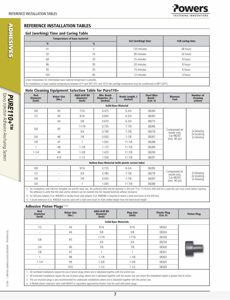
reference inStaLLation tabLeS
Gel (working) Time and Curing TableTemperature of base material
Gel (working) time Full curing timeºF ºC
41 5 120 minutes 48 hours
50 10 90 minutes 24 hours
68 20 25 minutes 8 hours
86 30 20 minutes 8 hours
95 35 15 minutes 6 hours
104 40 12 minutes 4 hours
Linearinterpolationforintermediatebasematerialtemperatureispossible.Forinstallationsinbasematerialtemperaturesbetween41ºFand50ºF(5ºCand10ºC)thecartridgetemperaturemustbeconditionedto68ºF(20ºC).
Hole Cleaning Equipment Selection Table for Pure110+Rod
Diameter (inch)
Rebar Size (No.)
ANSI Drill Bit Diameter1
(inch)
Min. Brush Diameter, Dmin
(inches)
Brush Length, L(inches)
Steel Wire Brush2,3 (Cat. #)
Blowout Tool
Number of cleaning actions
Solid Base Material
3/8 #3 7/16 0.475 6-3/4 08284
Compressed air nozzle only,Cat #8292
(min. 90 psi)
2x blowing2x brushing2x blowing
1/2 #4 9/16 0.600 6-3/4 08285
- #4 5/8 0.670 6-3/4 08275
5/8 #511/16 0.735 7-7/8 08286
3/4 0.790 7-7/8 08278
3/4 #6 7/8 0.920 7-7/8 08287
7/8 #7 1 1.045 11-7/8 08288
1 #8 1-1/8 1.175 11-7/8 08289
1-1/4 #9 1-3/8 1.425 11-7/8 08290
- #10 1-1/2 1.550 11-7/8 08291
Hollow Base Material (with plastic screen tube)
3/8 - 9/16 0.735 6-3/4 08285Compressed air
nozzle only,Cat #8292
(min. 90 psi)
2x blowing2x brushing2x blowing
1/2 - 3/4 0.780 7-7/8 08278
5/8 - 7/8 0.920 7-7/8 08287
3/4 - 1 1.045 11-7/8 08288
3. Forinstallationswith5/8-inchthreadedrodand#5rebarsize,thepreferredANSIdrillbitdiameteris3/4-inch.Ifan11/16-inchANSIdrillbitisusedtheusermustcheckbeforeinjectingtheadhesivetoverifythatthesteelanchorelementcanbeinsertedintothecleanedboreholewithoutresistance.
4. AnSDS-plusadaptor(Cat.#08283)orJacobschuckstyleadaptor(Cat.#08296)isrequiredtoattachasteelwirebrushtothedrilltool.5. Abrushextension(Cat.#08282)mustbeusedwithasteelwirebrushforholesdrilleddeeperthanthelistedbrushlength.
Adhesive Piston Plugs1,2,3,4
RodDiameter
(inch)
Rebar Size(No.)
ANSI Drill Bit Diameter
(inch)
Plug Size(inch)
Plastic Plug(Cat. #) Piston Plug
Solid Base Materials
1/2 #4 9/16 9/16 08302
- #4 5/8 5/8 08304
5/8 #511/16 11/16 08258
3/4 3/4 08259
3/4 #6 7/8 7/8 08300
7/8 #7 1 1 08301
1 #8 1-1/8 1-1/8 08303
1-1/4 #9 1-3/8 1-3/8 08305
- #10 1-1/2 1-1/2 08309
1. Alloverheadinstallationsrequiretheuseofpistonplugswhereoneistabulatedtogetherwiththeanchorsize.2. Allhorizontalinstallationsrequiretheuseofpistonplugswhereoneistabulatedtogetherwiththeanchorsizeandwheretheembedmentdepthisgreaterthan8inches.3. Theuseofpistonplugsisalsorecommendedforunderwaterinstallationswhereoneistabulatedtogetherwiththeanchorsize.4. Aflexibleplasticextensiontube(cat#08297)orequivalentapprovedbyPowersmustbeusedwithpistonplugs.
7

www.powers.com 2
Ad
hesiv
es
referenCe Data (aSD)
TECH
MAN
UAL
– Ad
HEsi
vEs
©20
15 P
OW
ERs
vO
LUM
E 1
– R
Ev. g
reference data (aSd)
Installation Table for Pure110+ (Solid Concrete Base Materials)Dimension/Property Notation Units Nominal Anchor Size
Threaded Rod - - 3/8 1/2 5/8 3/4 7/8 1 - 1-1/4 -
Reinforcing Bar - - #3 #4 #5 #6 #7 #8 #9 - #10
Nominal anchor diameter d in.(mm)
0.375(9.5)
0.500(12.7)
0.625(15.9)
0.750(19.1)
0.875(22.5)
1.000(25.4)
1.125(28.6)
1.250(31.8)
1.250(31.8)
Carbide drill bit nominal size dbit in. 7/16ANsi
9/16ANsi
11/16 or 3/4ANsi
7/8ANsi
1ANsi
1-1/8ANsi
1-3/8ANsi
1-3/8ANsi
1-1/2ANsi
Minimum embedment hnom in.
(mm)2-3/8(61)
2-3/4(70)
3-1/8(80)
3-1/2(89)
3-1/2(89)
4(102)
4-1/2(114)
5(127)
5(127)
Minimum spacing distance smin in.
(mm)1-7/8(48)
2-1/2(62)
3-1/8(80)
3-3/4(95)
4-3/8(111)
5(127)
5-5/8(143)
6-1/4(159)
6-1/4(159
Minimum edge distance cmin in.
(mm)1-7/8(48)
2-1/2(62)
3-1/8(80)
3-3/4(95)
4-3/8(111)
5(127)
5-5/8(143)
6-1/4(159)
6-1/4(159
Maximum torque1
Tmax
ft.-lb. (N-m)
15(20)
30(41)
60(81)
105(142)
125(169)
165(223)
200(270)
280(379)
280(379)
Maximum torque(low strength rods)1,2
ft.-lb. (N-m)
5(7)
20(27)
40(54)
60(81)
100(136)
165(223) - 280
(379) -
1. Torquemaynotbeappliedtotheanchorsuntilthefullcuretimeoftheadhesivehasbeenachieved.2. ThesetorquevaluesapplytoASTMA36/F1554,Grade36carbonsteelthreadedrods;ASTMF1554Grade55carbonsteelthreadedrods;andASTMA193GradeB8/B8M(Class1)
stainlesssteelthreadedrods.
Installation Table for Pure110+ (Hollow Base Material with Screen Tube)
Dimensions/property Notation UnitsNominal Size - Plastic
3/8” 1/2” 5/8” 3/4”
Nominal threaded rod diameter d in (mm)
0.375 (9.5)
0.500 (12.7)
0.625 (15.9)
0.750 (19.0)
Nominal screen tube diameter - in. 3/8 1/2 5/8 3/4
Nominal diameter of drilled hole dbit in. 9/16 ANsi
3/4 ANsi
7/8 ANsi
1 ANsi
Maximum torque (only possible after full cure time of adhesive) Tmax
ft.-lb. (N-m)
10 (8)
10 (8)
10 (8)
10 (8)
Detail of Steel Hardware Elements used with Injection Adhesive System
Threaded Rod and Deformed Reinforcing Bar Material PropertiesSteel
Description (General)
Steel Specification
(ASTM)
Nominal Anchor Size
(inch)
Minimum Yield Strength,
fy (ksi)
Minimum Ultimate Strength,
fu (ksi)
Carbon steel
A 36 or F1554 grade 36
3/8 through 1-1/4 36.0 58.0
F 1554 grade 55 55.0 75.0
A 4493/8 through 1 92.0 120.0
1-1/4 81.0 105.0
A 193, grade B7 or F 1554, grade 105 3/8 through 1-1/4 105.0 125.0
F 568M Class 5.8 3/4 through 1-1/4 58.0 72.5
stainless steel
F 593,Condition CW
3/8 through 5/8 65.0 100.0
3/4 through 1-1/4 45.0 85.0
A 193/A193M grade B8/B8M2,
Class 13/4 through 1-1/4 30.0 75.0
A 193/A193M grade B8/B8M2,
Class 2B3/8 through 1-1/4 75.0 95.0
grade 40Reinforcing Bar A 615, A 767 3/8 through 3/4
(#3 through #6) 40.0 60.0
grade 60Reinforcing Bar
A 615, A 767 3/8 through 1-1/4(#3 through #10)
60.0 90.0
A 706, A 767 60.0 80.0
grade 75Reinforcing Bar A 615, A 767 3/8 through 1-1/4
(#3 through #10) 75.0 100.0
Tmax
hnom
h
c
c
s
d
dbit
Threaded Rodor Rebar
Nomenclature
d = diameter of anchordbit = diameter of drilled holeh = Base material thickness
The greater of: [hnom + 1-1/4"] and [hnom + 2dbit]
hnom = Minimum embedment depth
8

Ad
hesiv
es
www.powers.com 3
TECH MAN
UAL – AdHEsivEs ©2015 PO
WERs vO
LUME 1 – REv. g
referenCe Data (aSD)
Ultimate and Allowable Load Capacities for Pure110+ Installed with Threaded Rod into Normal Weight Concrete (based on bond strength/concrete capacity)1,2,3,4,5,6,7
Rod Diameter
d in.
Drill Diameter
dbit in.
Minimum Embedment Depth
in.(mm)
Minimum Concrete Compressive Strength
f’c = 3,000 psi (20.7 MPa) f’c = 4,000 psi (27.6 MPa)
Ultimate Tension Load Capacity
lbs.(kN)
Allowable Tension Load Capacity
lbs.(kN)
Ultimate Tension Load Capacity
lbs.(kN)
Allowable Tension Load Capacity
lbs.(kN)
3/8 7/16 3-3/8(85.7)
10,445(46.5)
2,610(11.6)
10,445(46.5)
2,610(11.6)
1/2 9/16 4 1/2(114.3)
17,470(77.7)
4,370(19.4)
20,225(90.0)
5,055(22.5)
5/8 11/16 or 3/4 5-5/8(142.9)
23,335(103.8)
5,835(26.0)
28,600(127.2)
7,150(31.8)
3/4 7/8 6-3/4(171.5)
36,255(161.3)
9,065(40.3)
40,930(182.1)
10,235(45.5)
7/8 1 7-7/8(200.0)
46,275(205.8)
11,570(51.5)
52,920(235.4)
13,230(58.8)
1 1-1/8
9(228.6)
57,015(253.6)
14,255(63.4)
79,295(352.7)
19,825(88.2)
10(254.0)
77,445(344.5)
19,360(86.1)
82,745(368.1)
20,685(92.0)
1-1/4 1-3/8 11-1/4(285.8)
91,885(408.7)
22,970(102.2)
98,170(436.7)
24,545(109.2)
1. Allowableloadcapacitieslistedarecalculatedusinganappliedsafetyfactorof4.0.Considerationofsafetyfactorsof10orhighermaybenecessarydependingontheapplication,suchaslifesafetyoroverhead.
2. Linearinterpolationmaybeusedtodetermineallowableloadsforintermediateembedmentsandcompressivestrengths.3. Thetabulatedloadvaluesareapplicabletosingleanchorsinstalledatcriticaledgeandspacingdistancesandwheretheminimummemberthicknessisthegreaterof[hnom+1-1/4"]
and[hnom+2dbit]4. Thetabulatedloadvaluesareapplicablefordryconcrete.HolesmustbedrilledwithahammerdrillandanANSIcarbidedrillbit.Installationsinwater-saturatedconcrete(wet)orin
water-filledholes(flooded)requirea15%reductionincapacity.Installationsinunderwaterconcrete(submerged)requirea30%reductionincapacity.ContactPowersFastenersformoreinformationconcerningtheseinstallationconditions.
5. Adhesivesexperiencereductionsincapacityatelevatedtemperatures.Seethein-servicetemperaturechartforallowableloadcapacityreductionfactors.6. Allowablebondstrength/concretecapacitymustbecheckedagainstallowablesteelstrengthintensiontodeterminethecontrollingallowableload.7. Allowableshearcapacityiscontrolledbyallowablesteelstrengthforthegivenconditions.
Ultimate and Allowable Load Capacities for Pure110+ Installed with Reinforcing Bar into Normal Weight Concrete (based on bond strength/concrete capacity)1,2,3,4,5,6,7
Bar Diameter
d #
Drill Diameter
dbit in.
MinimumEmbedment Depth
in.(mm)
Minimum Concrete Compressive Strength
f’c = 3,000 psi (20.7 MPa) f’c = 4,000 psi (27.6 MPa)
Ultimate Tension Load Capacity
lbs.(kN)
Allowable Tension Load Capacity
lbs.(kN)
Ultimate Tension Load Capacity
lbs.(kN)
Allowable Tension Load Capacity
lbs.(kN)
#3 7/16 3-3/8(85.7)
11,155(49.6)
2,790(12.4)
11,155(49.6)
2,790(12.4)
#4 9/16 4-1/2(114.3)
17,735(78.9)
4,435(19.7)
19,200(85.4)
4,800(21.4)
#5 11/16 or 3/4
4(101.6)
16,740(74.5)
4,185(18.6)
16,910(75.2)
4,230(18.8)
5-5/8(142.9)
23,420(104.2)
5,855(26.0)
25,705(114.3)
6,425(28.6)
#6 7/8 6-3/4(171.5)
34,266(152.4)
8,565(38.1)
40,775(181.4)
10,195(45.3)
#8 1-1/8 9(228.6)
55,140(245.3)
13,785(61.3)
72,575(322.8)
18,145(80.7)
1. Allowableloadcapacitieslistedarecalculatedusinganappliedsafetyfactorof4.0.Considerationofsafetyfactorsof10orhighermaybenecessarydependingontheapplication,suchaslifesafetyoroverhead.
2. Linearinterpolationmaybeusedtodetermineallowableloadsforintermediateembedmentsandcompressivestrengths.3. ThetabulatedloadvaluesareapplicabletosingleanchorsinstalledatcriticaledgeandspacingdistancesandwheretheminimummemberthicknessisThegreaterof[hnom+1-1/4"]
and[hnom+2dbit].4. Thetabulatedloadvaluesareapplicablefordryconcrete.HolesmustbedrilledwithahammerdrillandanANSIcarbidedrillbit.Installationsinwater-saturatedconcrete(wet)orin
water-filledholes(flooded)requirea15%reductionincapacity.Installationsinunderwaterconcrete(submerged)requirea30%reductionincapacity.ContactPowersFastenersformoreinformationconcerningtheseinstallationconditions.
5. Adhesivesexperiencereductionsincapacityatelevatedtemperatures.Seethein-servicetemperaturechartforallowableloadcapacityreductionfactors.6. Allowablebondstrength/concretecapacitymustbecheckedagainstallowablesteelstrengthintensiontodeterminethecontrollingallowableload.7. Allowableshearcapacityiscontrolledbyallowablesteelstrengthforthegivenconditions.
9

www.powers.com 4
Ad
hesiv
es
referenCe Data (aSD)
TECH
MAN
UAL
– Ad
HEsi
vEs
©20
15 P
OW
ERs
vO
LUM
E 1
– R
Ev. g
Allowable Load Capacities for Pure110+ Installed into Uncracked Normal-Weight Concrete with Threaded Rod and Reinforcing Bar (Based on Steel Strength)1,2,3
Nominal Rod
Diameter or Rebar
Size(in. or #)
Steel Elements - Threaded Rod and Reinforcing Bar
A36 or F1554, Grade 36 A 193, Grade B7 or F1554, Grade 105 F 593, CW (SS) Grade 60 Rebar Grade 40 Rebar
Tensionlbs
(kN)
Shearlbs
(kN)
Tensionlbs
(kN)
Shearlbs
(kN)
Tensionlbs
(kN)
Shearlbs
(kN)
Tensionlbs
(kN)
Shearlbs
(kN)
Tensionlbs
(kN)
Shearlbs
(kN)
3/8 or #3 2,115(9.4)
1,090(4.8)
4,555(20.3)
2,345(10.4)
3,645(16.2)
1,880(8.4)
3,280(14.6)
1,690(7.5)
2,185(9.7)
1,125(5.0)
1/2 or #4 3,760(16.7)
1,935(8.6)
8,100(36.0)
4,170(18.5)
6,480(28.8)
3,340(14.9)
5,830(25.9)
3,005(13.4)
3,890(17.3)
2,005(8.9)
5/8 or #5 5,870(26.1)
3,025(13.5)
12,655(56.3)
6,520(29.0)
10,125(45.0)
5,215(23.2)
9,110(40.5)
4,695(20.9)
6,075(27.0)
3,130(13.9)
3/4 or #6 8,455(37.6)
4,355(19.4)
18,225(81.1)
9,390(41.8)
12,390(55.1)
6,385(28.4)
13,120(58.4)
6,760(30.1)
8,745(38.9)
4,505(20.0)
7/8 or #7 11,510(51.2)
5,930(26.4)
24,805(110.3)
12,780(56.8)
16,865(75.0)
8,690(38.7)
17,860(79.4)
9,200(40.9)
11,905(53.0)
6,135(27.3)
1 or #8 15,035(66.9)
7,745(34.5)
32,400(144.1)
16,690(74.2)
22,030(98.0)
11,350(50.5)
23,325(103.8)
12,015(53.4)
15,550(69.2)
8,010(35.6)
#9 - - - - - 29,680(132.0)
15,290(68.0)
19,785(88.0)
10,195(45.3)
1-1/4 23,490(104.5)
12,100(53.8)
50,620(225.2)
26,080(116.0)
34,425(153.1)
17,735(78.9) - - - -
#10 - - - - - - 37,625(167.4)
19,380(86.2)
25,080(111.6)
12,920(57.5)
1. AISCdefinedsteelstrength(ASD):Tensile=0.33•Fu•Anom,Shear=0.17•Fu•Anom
2. Allowablesteelstrengthintensionmustbecheckedagainstallowablebondstrength/concretecapacityintensiontodeterminethecontrollingallowableload.3. Thetabulatedloadvaluesareapplicabletosingleanchorsinstalledatcriticaledgeandspacingdistancesandwheretheminimummemberthicknessis2.5timestheembedmentdepth.
In-Service Temperature Chart For Allowable Load Capacities1
BASE MATERIAL TEMPERATUREREDUCTION FACTOR FOR TEMPERATURE
°F °C
32 0 0.89
41 5 1.00
50 10 1.00
70 20 1.00
110 43 1.00
130 54 0.82
150 66 0.73
180 82 0.48
1. Linearinterpolationmaybeusedtoderivereductionfactorsfortemperaturesbetweenthoselisted.
10

Ad
hesiv
es
www.powers.com 5
TECH MAN
UAL – AdHEsivEs ©2015 PO
WERs vO
LUME 1 – REv. g
referenCe Data (aSD)
Ultimate and Allowable Load Capacities for Threaded Rod Installed with Pure110+ into Grout Filled Masonry1,2,3,4,5
Anchor Installed Into Grouted Masonry Wall Faces
Nominal Diameter
d in.
Minimum Embed.
hv
in. (mm)
NominalDrillBit
Diameterin.
Minimum End
Distance in.
(mm)
Minimum Edge
Distance in.
(mm)
Ultimate Load Allowable Load
Tension lbs. (kN)
Shear lbs. (kN)
Tension lbs. (kN)
Shear lbs. (kN)
3/8 3(76.2) 7/16 ANsi 12
(304.8)12
(304.8)6,005(26.7)
5,200(23.1)
1,200(5.3)
1,040(4.6)
1/2 4(101.6) 9/16 ANsi 12
(304.8)12
(304.8)8,650(38.5)
8,845(39.3)
1,730(7.7)
1,770(7.9)
5/8 5(127) 11/16 ANsi 12
(304.8)12
(304.8)12,840(57.1)
8,430(37.5)
2,570(11.4)
1,685(7.5)
3/4 6(152.4) 7/8 ANsi 20
(508)20
(508)19,560(87.0)
12,685(56.4)
3,910(17.4)
2,540(11.3)
Anchor Installed in the Tops of Grouted Masonry Walls6
Nominal Diameter
d in.
Minimum Embed.
hv
in. (mm)
NominalDrillBit
Diameterin.
Minimum End
Distance in.
(mm)
Minimum Edge
Distance in.
(mm)
Ultimate Load Allowable Load
Tension lbs. (kN)
Shear lbs. (kN)
Tension lbs. (kN)
Shear lbs. (kN)
1/2 4(101.6) 9/16 ANsi 1.75
(44.5)4
(101.6)5,135(22.8)
1,750(7.8)
1,030(4.6)
350(1.6)
5/8 5(127) 11/16 ANsi 2.75
(69.9)4
(101.6)5,360(23.6)
3,130(13.9)
1,070(4.8)
625(2.8)
1. Tabulatedloadvaluesarefor3/8”and1/2”diameteranchorsinstalledinminimum6”wide,GradeN,TypeII,lightweightconcretemasonryunitsconformingtoASTMC90thathavereachedtheminimumdesignatedultimatecompressivestrengthatthetimeofinstallation(f’m≥1,500psi).
2. Tabulatedloadvaluesarefor5/8”and3/4”diameteranchorsinstalledin8”wide,GradeN,TypeII,lightweightconcretemasonryunitsconformingtoASTMC90thathavereachedtheminimumdesignatedultimatecompressivestrengthatthetimeofinstallation(f’m≥1,500psi).
3. Anchorsmustbeinstalledingroutedcellsandtheminimumedgeandenddistancesmustbemaintained.4. Allowableloadcapacitieslistedarecalculatedusinganappliedsafetyfactorof5.0andmustbecheckedagainsttheallowabletensionandshearcapacitiesforthreadedrodbasedon
steelstrengthtodeterminethecontrollingfactor.5. Thetabulatedvaluesareapplicableforanchorsinstalledintogroutedmasonrywallfacesandmasonrywalltopsatacriticalspacingdistance,scr,betweenanchorsof3timesthe
embedmentdepth.6. Anchorinstallationsintotopsofgroutedmasonrywallsarelimitedtoonepermasonrycell.
Minimum End Distance (Typ)
Minimum Edge Distance (Typ)
Wall FacePermissible Anchor Locations
(Un-hatched Area)
Mortar Joint
Grout Filled CMU (Typ)
Top of Wall
Minimum End Distance (Typ)
Minimum Edge Distance (Typ)
Ultimate and Allowable Load Capacities for Threaded Rod Installed with Pure110+ in Hollow Concrete Masonry Wall with Plastic Screen Tubes1,2,3
Nominal Anchor Diameter
in.
Minimum Screen Tube Length
in.
Minimum End Distance
in.(mm)
Minimum Edge Distance
in.(mm)
ASTM C-90 Block Type
Ultimate Load Allowable Load
Tensionlbs.(kN)
Tensionlbs.(kN)
3/8 3-1/2 3-3/4(95.3)
3-3/4(95.3) Lightweight 790
(3.5)160(0.7)
1/2 3-1/2 3-3/4(95.3)
3-3/4(95.3) Lightweight 1,255
(5.6)250(1.1)
5/8 6 3-3/4(95.3)
3-3/4(95.3) Normal-weight4 1,545
(6.9)310(1.4)
3/4 6 3-3/4(95.3)
3-3/4(95.3) Normal-weight4 1,545
(6.9)310(1.4)
1. Tabulatedloadvaluesareforanchorsinstalledinminimum8”wide,GradeN,TypeII,lightweightornormalweightconcretemasonryunitsconformingtoASTMC90thathavereachedadesignatedultimatecompressivestrengthatthetimeofinstallation(f’m≥1,500psi).MortarmustbetypeN,SorM.
2. Allowableloadsarecalculatedusinganappliedsafetyfactorof5.0.Considerationofsafetyfactorsof10orhighermaybenecessarydependingontheapplication,suchaslifesafety.3. Anchorspacingislimitedtoonepermasonrycell.4. Thetabulatedloadvaluesareapplicabletonormal-weightconcretemasonryunitswithaminimumfaceshellthicknessof1-1/2inches.
11

www.powers.com 6
Ad
hesiv
es
StrenGth DeSIGn (SD)
TECH
MAN
UAL
– Ad
HEsi
vEs
©20
15 P
OW
ERs
vO
LUM
E 1
– R
Ev. g
Strength deSign (Sd)
Installation Specifications for Threaded Rod and Reinforcing Bar1 Code listedICC-eS eSr-3298
Parameter Symbol UnitsFractional Nominal Rod Diameter (Inch) / Reinforcing Bar Size
3/8 or #3
1/2 or #4
5/8 or #5
3/4 or #6
7/8 or #7 1 or #8 #9 1-1/4 #10
Threaded rod outside diameter d inch(mm)
0.375(9.5)
0.500(12.7)
0.625(15.9)
0.750(19.1)
0.875(22.2)
1.000(25.4) - 1.250
(31.8) -
Rebar nominal outside diameter d inch(mm)
0.375(9.5)
0.500(12.7)
0.625(15.9)
0.750(19.1)
0.875(22.2)
1.000(25.4)
1.125(28.7) - 1.250
(31.8)
Carbide drill bit nominal size do (dbit) inch 7/16 9/16 11/16 or 3/4 7/8 1 1-1/8 1-3/8 1-3/8 1-1/2
Minimum embedment hef,mininch(mm)
2-3/8(60)
2-3/4(70)
3-1/8(79)
3-1/2(89)
3-1/2(89)
4(102)
4-1/2(114)
5(127)
5(127)
Maximum embedment hef,maxinch(mm)
7-1/2(191)
10(254)
12-1/2(318)
15(381)
17-1/2(445)
20(508)
22-1/2(572)
25(635)
25(635)
Minimum member thickness hmininch(mm)
hef + 1-1/4(hef + 30) hef + 2do
Minimum anchor spacing smininch(mm)
1-7/8(48)
2-1/2(64)
3-1/8(79)
3-3/4(95)
4-3/8(111)
5(127)
5-5/8(143)
6-1/4(159)
6-1/4(159)
Minimum edge distance cmininch(mm)
1-7/8(48)
2-1/2(64)
3-1/8(79)
3-3/4(95)
4-3/8(111)
5(127)
5-5/8(143)
6-1/4(159)
6-1/4(159)
Max. torque2 Tmaxft-lbs(N-m)
15(20)
30(41)
60(81)
105(142)
125(169)
165(221)
200(280)
280(379)
280(379)
Max. torque2,3
(low strength rods) Tmaxft-lbs(N-m)
5(7)
20(27)
40(54)
60(81)
100(136)
165(223) - 280
(379) -
Minimum edge distance, reduced5 cmin,redinch(mm)
1-3/4(45)
1-3/4(45)
1-3/4(45)
1-3/4(45)
1-3/4(45)
1-3/4(45)
2-3/4(70)
2-3/4(70)
2-3/4(70)
Max. torque, reduced2 Tmax,redft-lbs(N-m) 7 [5]4 14
(19)27
(37)47
(64)56
(76)74
(100)90
(122)126
(171)126
(171)
Forpound-inchunits:1mm=0.03937inch,1N-m=0.7375ft-lbf.ForSI:1inch=25.4mm,1ft-lbf=1.356N-m.1. ForusewiththedesignprovisionsofACI318AppendixD,ICC-ESAC308,Section4.2andESR-32982. Torquemaynotbeappliedtotheanchorsuntilthefullcuretimeoftheadhesivehasbeenachieved.3. ThesetorquevaluesapplytoASTMA36/F1554Grade36carbonsteelthreadedrods;ASTMF1554Grade55carbonsteelthreadedrods;andASTMA193GradeB8/B8M(Class1)
stainlesssteelthreadedrods.4. ThesetorquevaluesapplytoASTMA193GradeB8/B8M(Class1)stainlesssteelthreadedrods.5. ForInstallationbetweentheminimumedgedistance,cmin,andthereducedminimumedgedistance,cmin,red,themaximumtorqueappliedmustbemaxtorquereduced,Tmax,red.
Detail of Steel Hardware Elements used with Injection Adhesive System
Threaded Rod and Deformed Reinforcing Bar Material Properties
Steel Description (General)
Steel Specification (ASTM)
Nominal Anchor Size (inch)
Minimum Yield
Strength, fy (ksi)
Minimum Ultimate Strength,
fu (ksi)
Carbon rod
A 36 or F 1554 grade 363/8 through 1-1/4
36.0 58.0
F 1554 grade 55 55.0 75.0
A 4493/8 through 1 92.0 120.0
1-1/4 81.0 105.0
A 193, grade B7 or F 1554, grade 105 3/8 through 1-1/4 105.0 125.0
F 568M Class 5 8 3/4 through 1-1/4 58.0 72.5
stainless rod
F 593 Condition CW3/8 through 5/8 65.0 100.0
3/4 through 1-1/4 45.0 85.0
A 193/193Mgrade B8/B8M,
Class 13/8 through 1-1/4 30.0 75.0
A 193/A193Mgrade B8/B8M2, Class 2B 3/8 through 1-1/4 75.0 95.0
grade 40 Reinforcing Bar A 615, A 767 3/8 through 1-1/4
(#3 through #10) 40.0 60.0
grade 60 Reinforcing Bar
A 615, A 767 3/8 through 1-1/4(#3 through #10)
60.0 90.0
A 706, A 767 60.0 80.0
grade 75 Reinforcing Bar A 615, A 767 3/8 through 1-1/4
(#3 through #10) 75.0 100.0
Tmax
hef
h
c
c
s
d
do(dbit)
Threaded Rodor Rebar
12

Ad
hesiv
es
www.powers.com 7
TECH MAN
UAL – AdHEsivEs ©2015 PO
WERs vO
LUME 1 – REv. g
StrenGth DeSIGn (SD)
Steel Tension and Shear Design for Threaded Rod in Normal Weight Concrete(For use with load combinations taken from ACI318 Section 9.2)
Code listedICC-eS eSr-3298
Design Information Symbol UnitsNominal Rod Diameter1 (inch)
3/8 1/2 5/8 3/4 7/8 1 1-1/4
Threaded rod nominal outside diameter d inch(mm)
0.375(9.5)
0.500(12.7)
0.625(15.9)
0.750(19.1)
0.875(22.2)
1.000(25.4)
1.250(31.8)
Threaded rod effective cross-sectional area Aseinch2
(mm2)0.0775
(50)0.1419
(92)0.2260(146)
0.3345(216)
0.4617(298)
0.6057(391)
0.9691(625)
AsTM A 36 and
AsTM F 1554 grade 36
Nominal strength as governed by steel strength (for a single anchor)
Nsalbf
(kN)4,495(20.0)
8,230(36.6)
13,110(58.3)
19,400(86.3)
26,780(119.1)
35,130(156.3)
56,210(250.0)
vsalbf
(kN)2,695(12.0)
4,940(22.0)
7,860(35.0)
11,640(51.8)
16,070(71.4)
21,080(93.8)
33,725(150.0)
Reduction factor for seismic shear αV,seis - 0.80 0.80 0.80 0.80 0.80 0.80 0.80strength reduction factor for tension2 φ - 0.75strength reduction factor for shear2 φ - 0.65
AsTM F 1554 grade 55
Nominal strength as governed by steel strength(for a single anchor)
Nsalbf
(kN)5,810(25.9)
10,640(47.3)
16,950(75.4)
25,085(111.6)
34,625(154.0)
45,425(202.0)
72,680(323.3)
Vsalbf
(kN)3,485(15.5)
6,385(28.4)
10,170(45.2)
15,050(67.0)
20,775(92.4)
27,255(121.2)
43,610(194.0)
Reduction factor for seismic shear αV,seis - 0.80 0.80 0.80 0.80 0.80 0.80 0.80strength reduction factor for tension2 φ - 0.75strength reduction factor for shear2 φ - 0.65
AsTM A 193grade B7
and AsTM F 1554
grade 105
Nominal strength as governed by steel strength (for a single anchor)
Nsalbf
(kN)9,685(43.1)
17,735(78.9)
28,250(125.7)
41,810(186.0)
57,710(256.7)
75,710(336.8)
121,135(538.8)
vsalbf
(kN)5,815(25.9)
10,640(7.3)
16,950(75.4)
25,085(111.6)
34,625(154.0)
45,425(202.1)
72,680(323.3)
Reduction factor for seismic shear αV,seis - 0.80 0.80 0.80 0.80 0.80 0.80 0.80strength reduction factor for tension2 φ - 0.75strength reduction factor for shear2 φ - 0.65
AsTM A 449
Nominal strength as governed by steel strength (for a single anchor)
Nsalbf
(kN)9,300(41.4)
17,025(75.7)
27,120(120.6)
40,140(178.5)
55,905(248.7)
72,685(323.3)
101,755(452.6)
vsalbf
(kN)5,580(24.8)
10,215(45.4)
16,270(72.4)
24,085(107.1)
33,540(149.2)
43,610(194.0)
61,050(271.6)
Reduction factor for seismic shear αV,seis - 0.80 0.80 0.80 0.80 0.80 0.80 0.80strength reduction factor for tension2 φ - 0.75strength reduction factor for shear2 φ - 0.65
isO 898-1Class 5.8
Nominal strength as governed by steel strength (for a single anchor)
Nsalbf
(kN)5,620(25.0)
10,290(45.8)
16,385(72.9)
24,250(107.9)
33,475(148.9)
43,915(195.4) -5
vsalbf
(kN)3,370(15.0)
6,175(27.5)
9,830(43.7)
14,550(64.7)
20,085(89.3)
26,350(117.2) -5
Reduction factor for seismic shear αV,seis - 0.80 0.80 0.80 0.80 0.80 0.80 -5
strength reduction factor for tension3 φ - 0.65strength reduction factor for shear3 φ - 0.60
AsTM F 593CW stainless(Types 304 and 316)
Nominal strength as governed by steel strength (for a single anchor)
Nsalbf
(kN)7,750(34.5)
14,190(63.1)
22,600(100.5)
28,430(126.5)
39,245(174.6)
51,485(229.0)
82,370(366.4)
vsalbf
(kN)4,650(20.7)
8,515(37.9)
13,560(60.3)
17,060(75.9)
23,545(104.7)
30,890(137.4)
49,425(219.8)
Reduction factor for seismic shear αV,seis - 0.70 0.70 0.80 0.80 0.80 0.80 0.80strength reduction factor for tension3 φ - 0.65strength reduction factor for shear3 φ - 0.60
AsTM A 193grade B8/B8M,
Class 1 stainless
(Types 304and 316)
Nominal strength as governed by steel strength (for a single anchor)4
Nsalbf
(kN)4,420(19.7)
8,090(36.0)
12,880(57.3)
19,065(84.8)
26,315(117.1)
34,525(153.6)
55,240(245.7)
vsalbf
(kN)2,650(11.8)
4,855(21.6)
7,730(34.4)
11,440(50.9)
15,790(70.2)
20,715(92.1)
33,145(147.4)
Reduction factor for seismic shear αV,seis - 0.70 0.70 0.80 0.80 0.80 0.80 0.80strength reduction factor for tension2 φ - 0.75strength reduction factor for shear2 φ - 0.65
AsTM A 193grade B8/
B8M2,Class 2B stainless
(Types 304 and 316)
Nominal strength as governed by steel strength (for a single anchor)
Nsalbf
(kN)7,365(32.8)
13,480(60.0)
21,470(95.5)
31,775(141.3)
43,860(195.1)
57,545(256.0)
92,065(409.5)
vsalbf
(kN)4,420(19.7)
8,085(36.0)
12,880(57.3)
19,065(84.8)
26,315(117.1)
34,525(153.6)
55,240(245.7)
Reduction factor for seismic shear αV,seis - 0.70 0.70 0.80 0.80 0.80 0.80 0.80strength reduction factor for tension2 φ - 0.75strength reduction factor for shear2 φ - 0.65
ForSI:1inch=25.4mm,1lbf=4.448N.Forpound-inchunits:1mm=0.03937inches,1N=0.2248lbf.1. ValuesprovidedforsteelelementmaterialtypesarebasedonminimumspecifiedstrengthsandcalculatedinaccordancewithACI318-11Eq.(D-2)andEq.(D-29)exceptwherenoted.
Nutsandwashersmustbeappropriatefortherod.Nutsmusthavespecifiedproofloadstressesequaltoorgreaterthantheminimumtensilestrengthofthespecifiedthreadedrod.2. ThetabulatedvalueofφapplieswhentheloadcombinationsofSection1605.2oftheIBCorACI318Section9.2areusedinaccordancewithACI318D.4.3.Iftheloadcombinationsof
ACI318AppendixCareused,theappropriatevalueofφmustbedeterminedinaccordancewithACI318D.4.4.Valuescorrespondtoductilesteelelements.3. ThetabulatedvalueofφapplieswhentheloadcombinationsofSection1605.2oftheIBCorACI318Section9.2areusedinaccordancewithACI318-11D.4.3.Iftheloadcombinations
ofACI318AppendixCareused,theappropriatevalueofφmustbedeterminedinaccordancewithACI318D.4.4.Valuescorrespondtobrittlesteelelements4. InaccordancewithACI318D.5.1.2andD.6.1.2thecalculatedvaluesfornominaltensionandshearstrengthforASTMA193GradeB8/B8MClass1stainlesssteelthreadedrodsare
basedonlimitingthespecifiedtensilestrengthoftheanchorsteelto1.9fyor57,000psi(393MPa).5. Thereferencedstandardincludesroddiametersuptoandincluding1-inch(24mm).
13

www.powers.com 8
Ad
hesiv
es
StrenGth DeSIGn (SD)
TECH
MAN
UAL
– Ad
HEsi
vEs
©20
15 P
OW
ERs
vO
LUM
E 1
– R
Ev. g
Steel Tension and Shear Design for Reinforcing Bars in Normal Weight Concrete(For use with load combinations taken from ACI318 Section 9.2)
Code listedICC-eS eSr-3298
Design Information Symbol UnitsNominal Reinforcing Bar Size (Rebar)1
No. 3 No. 4 No. 5 No. 6 No. 7 No. 8 No. 9 No. 10
Rebar nominal outside diameter d inch(mm)
0.375(9.5)
0.500(12.7)
0.625(15.9)
0.750(19.1)
0.875(22.2)
1.000(25.4)
1.125(28.7)
1.250(32.3)
Rebar effective cross-sectional area Aseinch2
(mm2)0.110(71.0)
0.200(129.0)
0.310(200.0)
0.440(283.9)
0.600(387.1)
0.790(509.7)
1.000(645.2)
1.270(819.4)
AsTMA 615
grade 75
Nominal strength as governed by steel strength (for a single anchor)
Nsalbf
(kN)11,000(48.9)
20,000(89.0)
31,000(137.9)
44,000(195.7)
60,000(266.9)
79,000(351.4)
100,000(444.8)
127,000(564.9)
vsalbf
(kN)6,600(29.4)
12,000(53.4)
18,600(82.7)
26,400(117.4)
36,000(160.1)
47,400(210.8)
60,000(266.9)
76,200(338.9)
Reduction factor for seismic shear αV,seis - 0.70 0.70 0.80 0.80 0.80 0.80 0.80 0.80
strength reduction factor for tension3 φ - 0.65
strength reduction factor for shear3 φ - 0.60
AsTMA 615
grade 60
Nominal strength as governed by steel strength (for a single anchor)
Nsalbf
(kN)9,900(44.0)
18,000(80.1)
27,900(124.1)
39,600(176.1)
54,000(240.2)
71,100(316.3)
90,000(400.3)
114,300(508.4)
vsalbf
(kN)5,940(26.4)
10,800(48.0)
16,740(74.5)
23,760(105.7)
32,400(144.1)
42,660(189.8)
54,000(240.2)
68,580(305.0)
Reduction factor for seismic shear αV,seis - 0.70 0.70 0.80 0.80 0.80 0.80 0.80 0.80
strength reduction factor for tension2 φ - 0.75
strength reduction factor for shear2 φ - 0.65
AsTM A 706 grade 60
Nominal strength as governed by steel strength (for a single anchor)
Nsalbf
(kN)8,800(39.1)
16,000(71.2)
24,800(110.3)
35,200(156.6)
48,000(213.5)
63,200(281.1)
80,000(355.9)
101,600(452.0)
vsalbf
(kN)5,280(23.5)
9,600(42.7)
14,880(66.2)
21,120(94.0)
28,800(128.1)
37,920(168.7)
48,000(213.5)
60,960(271.2)
Reduction factor for seismic shear αV,seis - 0.70 0.70 0.80 0.80 0.80 0.80 0.80 0.80
strength reduction factor for tension2 φ - 0.75
strength reduction factor for shear2 φ - 0.65
AsTM A 615 grade 40
Nominal strength as governed by steel strength (for a single anchor)
Nsalbf
(kN)6,600(29.4)
12,000(53.4)
18,600(82.7)
26,400(117.4) in accordance with AsTM A 615, grade
40 bars are furnished only in sizes No. 3 through No. 6vsa
lbf(kN)
3,960(17.6)
7,200(32.0)
11,160(49.6)
15,840(70.5)
Reduction factor for seismic shear αV,seis - 0.70 0.70 0.80 0.80
strength reduction factor for tension2 φ - 0.75
strength reduction factor for shear2 φ - 0.65
ForSI:1inch=25.4mm,1lbf=4.448N.Forpound-inchunits:1mm=0.03937inches,1N=0.2248lbf.1. ValuesprovidedforreinforcingbarmaterialtypesbasedonminimumspecifiedstrengthsandcalculatedinaccordancewithACI318-11Eq.(D-2)andEq.(D-29).2. ThetabulatedvalueofφapplieswhentheloadcombinationsofSection1605.2oftheIBCorACI318Section9.2areusedinaccordancewithACI318D.4.3.Iftheloadcombinationsof
ACI318AppendixCareused,theappropriatevalueofφmustbedeterminedinaccordancewithACI318D.4.4.Valuescorrespondtoductilesteelelements.3. ThetabulatedvalueofφapplieswhentheloadcombinationsofSection1605.2oftheIBCorACI318Section9.2areusedinaccordancewithACI318D.4.3.Iftheloadcombinationsof
ACI318AppendixCareused,theappropriatevalueofφmustbedeterminedinaccordancewithACI318D.4.4.Valuescorrespondtobrittlesteelelements.
14
Ad
hesiv
es
www.powers.com 9
TECH MAN
UAL – AdHEsivEs ©2015 PO
WERs vO
LUME 1 – REv. g
StrenGth DeSIGn (SD)
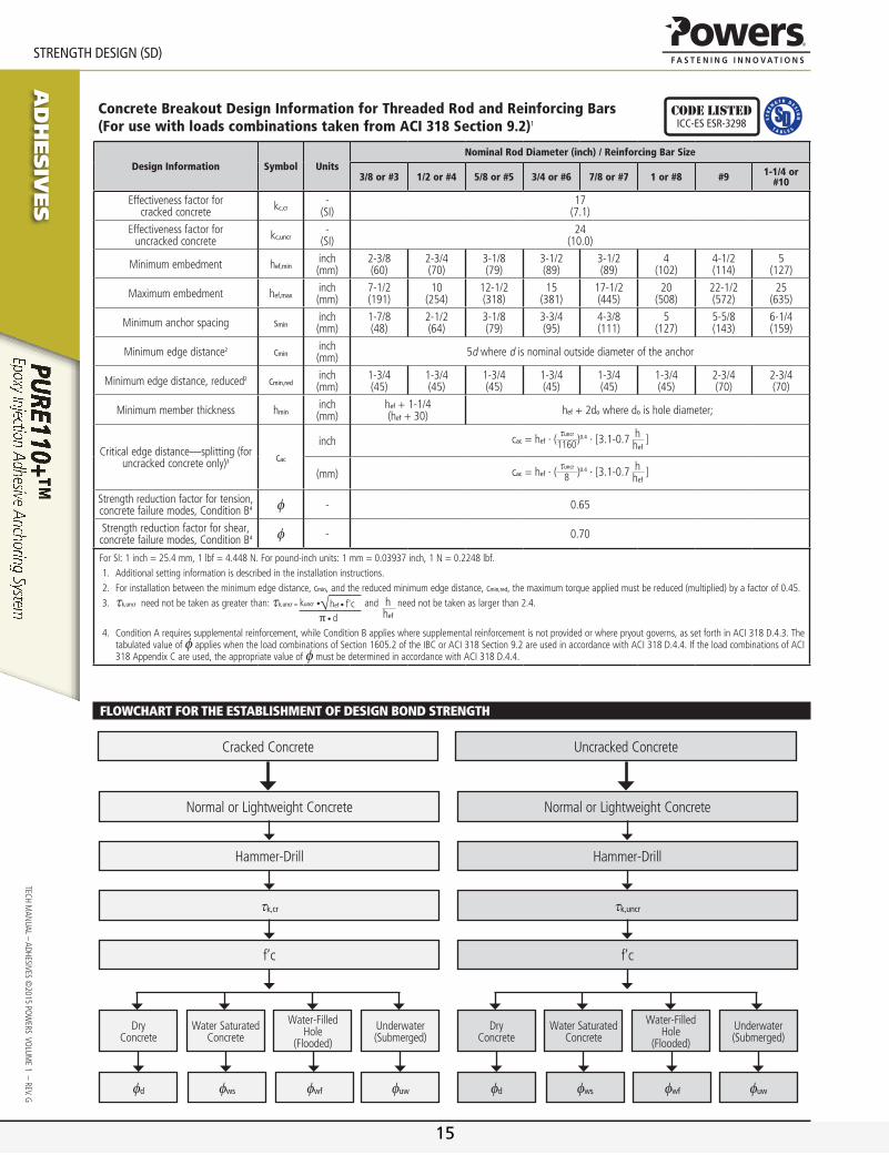
Concrete Breakout Design Information for Threaded Rod and Reinforcing Bars (For use with loads combinations taken from ACI 318 Section 9.2)1
Code listedICC-eS eSr-3298
Design Information Symbol UnitsNominal Rod Diameter (inch) / Reinforcing Bar Size
3/8 or #3 1/2 or #4 5/8 or #5 3/4 or #6 7/8 or #7 1 or #8 #9 1-1/4 or #10
Effectiveness factor for cracked concrete kc,cr
-(si)
17(7.1)
Effectiveness factor for uncracked concrete kc,uncr
-(si)
24(10.0)
Minimum embedment hef,mininch(mm)
2-3/8(60)
2-3/4(70)
3-1/8(79)
3-1/2(89)
3-1/2(89)
4(102)
4-1/2(114)
5(127)
Maximum embedment hef,maxinch(mm)
7-1/2(191)
10(254)
12-1/2(318)
15(381)
17-1/2(445)
20(508)
22-1/2(572)
25(635)
Minimum anchor spacing smininch(mm)
1-7/8(48)
2-1/2(64)
3-1/8(79)
3-3/4(95)
4-3/8(111)
5(127)
5-5/8(143)
6-1/4(159)
Minimum edge distance2 cmininch(mm) 5d where d is nominal outside diameter of the anchor
Minimum edge distance, reduced2 cmin,redinch(mm)
1-3/4(45)
1-3/4(45)
1-3/4(45)
1-3/4(45)
1-3/4(45)
1-3/4(45)
2-3/4(70)
2-3/4(70)
Minimum member thickness hmininch(mm)
hef + 1-1/4(hef + 30) hef + 2do where do is hole diameter;
Critical edge distance—splitting (for uncracked concrete only)3 cac
inch cac = hef ∙ (tuncr
1160)0.4 ∙ [3.1-0.7 hhef
]
(mm) cac = hef ∙ (tuncr
8 )0.4 ∙ [3.1-0.7 hhef
]
strength reduction factor for tension, concrete failure modes, Condition B4 φ - 0.65
strength reduction factor for shear, concrete failure modes, Condition B4 φ - 0.70
ForSI:1inch=25.4mm,1lbf=4.448N.Forpound-inchunits:1mm=0.03937inch,1N=0.2248lbf.1. Additionalsettinginformationisdescribedintheinstallationinstructions.2. Forinstallationbetweentheminimumedgedistance,cmin,andthereducedminimumedgedistance,cmin,red,themaximumtorqueappliedmustbereduced(multiplied)byafactorof0.45.3. tk,uncrneednotbetakenasgreaterthan:tk,uncr = √hef •f'ckuncr•
π •d
and hhef
neednotbetakenaslargerthan2.4.
4. ConditionArequiressupplementalreinforcement,whileConditionBapplieswheresupplementalreinforcementisnotprovidedorwherepryoutgoverns,assetforthinACI318D.4.3.ThetabulatedvalueofφapplieswhentheloadcombinationsofSection1605.2oftheIBCorACI318Section9.2areusedinaccordancewithACI318D.4.4.IftheloadcombinationsofACI318AppendixCareused,theappropriatevalueofφmustbedeterminedinaccordancewithACI318D.4.4.
Flowchart For the estaBlishment oF desiGn Bond strenGth
Cracked Concrete
Normal or Lightweight Concrete
dry Concrete
Water saturated Concrete
Water-Filled Hole
(Flooded)
Underwater (submerged)
φd φws φwf φuw
Hammer-drill
tk,cr
f’c
Uncracked Concrete
Normal or Lightweight Concrete
dry Concrete
Water saturated Concrete
Water-Filled Hole
(Flooded)
Underwater (submerged)
φd φws φwf φuw
Hammer-drill
tk,uncr
f’c
15

www.powers.com 10
Ad
hesiv
es
StrenGth DeSIGn (SD)
TECH
MAN
UAL
– Ad
HEsi
vEs
©20
15 P
OW
ERs
vO
LUM
E 1
– R
Ev. g
Bond Strength Design Information for Threaded Rods and Reinforcing Bars (For use with load combinations taken from ACI 318 Section 9.2)1,2
Code listedICC-eS eSr-3298
DESIGN INFORMATION SYMBOL UNITS
NOMINAL ROD DIAMETER (inch) / REINFORCING BAR SIZE
3/8 or #3
1/2 or #4
5/8 or #5
3/4 or #6
7/8 or #7 1 or #8 #9 11/4 or
#10
Minimum embedment hef,mininch(mm)
2-3/8(60)
2-3/4(70)
3-1/8(79)
3-1/2(89)
3-1/2(89)
4(102)
4-1/2(114)
5(127)
Maximum embedment hef,maxinch(mm)
7-1/2(191)
10(254)
12-1/2(318)
15(381)
17-1/2(445)
20(508)
22-1/2(572)
25(635)
75°F (24°C) Maximum Long-Term service Temperature;
104°F (40°C) Maximum short-Term service Temperature5,10
Characteristic bond strength in cracked
concrete6,9tk,cr
psi(N/mm2)
990(6.8)
990(6.8)
959(6.6)
959(6.6)
959(6.6)
918(6.3)
846(5.8)
846(5.8)
Characteristic bond strength in uncracked
concrete6,8tk,uncr
psi(N/mm2)
1,756(12.1)
1,668(11.5)
1,604(11.1)
1,553(10.7)
1,512(10.4)
1,477(10.2)
1,446(10.0)
1,420(9.8)
110°F (43°C) Maximum Long-Term service Temperature;
140°F (60°C) Maximum short-Term service Temperature3,5
Characteristic bond strength in cracked
concrete6,9tk,cr
psi(N/mm2)
990(6.8)
990(6.8)
959(6.6)
959(6.6)
959(6.6)
918(6.3)
846(5.8)
846(5.8)
Characteristic bond strength in uncracked
concrete6,8tk,uncr
psi(N/mm2)
1,756(12.1)
1,668(11.5)
1,604(11.1)
1,553(10.7)
1,512(10.4)
1,477(10.2)
1,446(10.0)
1,420(9.8)
110°F (43°C) Maximum Long-Term service Temperature;
176°F (80°C) Maximum short-Term service Temperature4,5
Characteristic bond strength in cracked
concrete6,9tk,cr
psi(N/mm2)
725(5.0)
725(5.0)
696(4.8)
696(4.8)
696(4.8)
667(4.6)
624(4.3)
624(4.3)
Characteristic bond strength in uncracked
concrete6,8tk,uncr
psi(N/mm2)
1,276(8.8)
1,218(8.4)
1,175(8.1)
1,131(7.6)
1,102(7.6)
1,073(7.4)
1,059(7.3)
1,030(7.1)
Permissible installation Conditions7
dry concreteAnchor
Category - 1
φd - 0.65
Water-saturated concrete,
Water-filled hole (flooded)
Anchor Category - 2
φws, φwf, - 0.55
Underwater (submerged)Anchor
Category - 2 3
φuw - 0.55 0.45
Reduction factor for seismic tension9 αn,seis - 1
ForSI:1inch=25.4mm,1psi=0.006894MPa.Forpound-inchunits:1mm=0.03937inch,1MPa=145.0psi.1. Bondstrengthvaluescorrespondtoanormal-weightconcretecompressivestrengthf'c=2,500psi(17.2MPa).Forconcretecompressivestrength,f'cbetween2,500psiand8,000psi
(17.2MPaand55.2MPa),thetabulatedcharacteristicbondstrengthmaybeincreasedbyafactorof(f'c/2,500)0.23[ForSI:(f'c/17.2)0.23].SeeSection4.1.4ofthisreportforbondstrengthdetermination.
2. ThemodificationfactorforbondstrengthofadhesiveanchorsinlightweightconcreteshallbetakenasgiveninACI318D.3.6,whereapplicable.3. Themaximumshort-termservicetemperaturemaybeincreasedto162°F(72°C)providedcharacteristicbondstrengthsarereducedby3percent.Long-termandshort-termtemperatures
meettherequirementsofSection8.5ofACI355.4andTable8.1,TemperatureCategoryB.4. Long-termandshort-termtemperaturesmeettherequirementsofSection8.5ofACI355.4andTable8.1,TemperatureCategoryA.5. Short-termbasematerialservicetemperaturesarethosethatoccuroverbriefintervals,e.g.asaresultofdiurnalcycling.Long-termbasematerialservicetemperaturesareroughly
constantoversignificantperiodsoftime.6. Characteristicbondstrengthsareforsustainedloadsincludingdeadandliveloads.7. Permissibleinstallationconditionsincludedryconcrete,water-saturatedconcrete,water-filledholesandunderwater.Water-filledholesincludeapplicationsindryorwater-saturated
concretewherethedrilledholescontainstandingwateratthetimeofanchorinstallation.8. BondstrengthvaluesforuncrackedconcreteareapplicableforstructuresassignedtoSeismicDesignCategoriesAandBonly.9. ForstructuresassignedtoSeismicDesignCategoriesC,D,EorF,thetabulatedbondstrengthvaluesforcrackedconcretedonotrequireanadditionalreductionfactorappliedforseismic
tension(αn,seis=1.0),whereseismicdesignisapplicable.10. Room temperature range is not recognized by ACI 318-11 and does not meet the minimum temperature requirements from ACI 355.4, Table 8.1. and
consequently is not applicable to design under ACI 318-11 or current and past editions of the International Building Code (IBC). The Tabulated values are provided for analysis and evaluation of existing conditions only.
16
Ad
hesiv
es
www.powers.com 11
TECH MAN
UAL – AdHEsivEs ©2015 PO
WERs vO
LUME 1 – REv. g
StrenGth DeSIGn (SD)
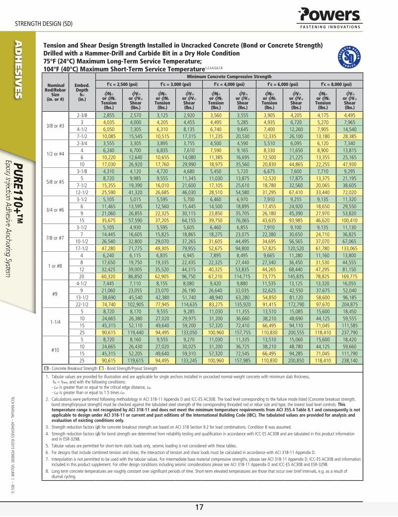
Tension and Shear Design Strength Installed in Uncracked Concrete (Bond or Concrete Strength)Drilled with a Hammer-Drill and Carbide Bit in a Dry Hole Condition75°F (24°C) Maximum Long-Term Service Temperature; 104°F (40°C) Maximum Short-Term Service Temperature1,2,3,4,5,6,7,8
Nominal Rod/Rebar
Size(in. or #)
Embed.Depth
hef
(in.)
Minimum Concrete Compressive Strength
f'c = 2,500 (psi) f'c = 3,000 (psi) f'c = 4,000 (psi) f'c = 6,000 (psi) f'c = 8,000 (psi)
φNcb
or φNa
Tension(lbs.)
φVcb
or φVcp
Shear(lbs.)
φNcb
or φNa
Tension(lbs.)
φVcb
or φVcp
Shear(lbs.)
φNcb
or φNa
Tension(lbs.)
φVcb
or φVcp
Shear(lbs.)
φNcb
or φNa
Tension(lbs.)
φVcb
or φVcp
Shear(lbs.)
φNcb
or φNa
Tension(lbs.)
φVcb
or φVcp
Shear(lbs.)
3/8 or #3
2-3/8 2,855 2,570 3,125 2,920 3,560 3,555 3,905 4,205 4,175 4,4953 4,035 4,000 4,205 4,455 4,495 5,285 4,935 6,720 5,270 7,965
4-1/2 6,050 7,305 6,310 8,135 6,740 9,645 7,400 12,260 7,905 14,5407-1/2 10,085 15,545 10,515 17,315 11,235 20,530 12,335 26,100 13,180 28,385
1/2 or #4
2-3/4 3,555 3,305 3,895 3,755 4,500 4,590 5,510 6,095 6,120 7,3404 6,240 6,700 6,835 7,610 7,590 9,165 8,330 11,650 8,900 13,8156 10,220 12,640 10,655 14,080 11,385 16,695 12,500 21,225 13,355 25,16510 17,030 26,920 17,760 29,990 18,975 35,560 20,830 44,865 22,255 47,930
5/8 or #5
3-1/8 4,310 4,120 4,720 4,680 5,450 5,720 6,675 7,600 7,710 9,2955 8,720 9,985 9,555 11,345 11,030 13,875 12,520 17,875 13,375 21,195
7-1/2 15,355 19,390 16,010 21,600 17,105 25,610 18,780 32,560 20,065 38,60512-1/2 25,590 41,320 26,685 46,030 28,510 54,580 31,295 67,410 33,440 72,020
3/4 or #6
3-1/2 5,105 5,015 5,595 5,700 6,460 6,970 7,910 9,255 9,135 11,3206 11,465 13,595 12,560 15,445 14,500 18,895 17,455 24,920 18,650 29,5509 21,060 26,855 22,325 30,115 23,850 35,705 26,180 45,390 27,970 53,82015 35,675 57,590 37,205 64,155 39,750 76,065 43,635 93,985 46,620 100,410
7/8 or #7
3-1/2 5,105 4,930 5,595 5,605 6,460 6,855 7,910 9,100 9,135 11,1307 14,445 16,605 15,825 18,865 18,275 23,075 22,380 30,650 24,710 36,825
10-1/2 26,540 32,800 29,070 37,265 31,605 44,495 34,695 56,565 37,070 67,06517-1/2 47,280 71,775 49,305 79,955 52,675 94,800 57,825 120,520 61,780 133,065
1 or #8
4 6,240 6,115 6,835 6,945 7,895 8,495 9,665 11,280 11,160 13,8008 17,650 19,750 19,335 22,435 22,325 27,440 27,340 36,450 31,530 44,55512 32,425 39,005 35,520 44,315 40,325 53,835 44,265 68,440 47,295 81,15020 60,320 86,850 62,905 96,750 67,210 114,715 73,775 145,835 78,825 169,775
#9
4-1/2 7,445 7,110 8,155 8,080 9,420 9,880 11,535 13,125 13,320 16,0559 21,060 23,055 23,070 26,190 26,640 32,035 32,625 42,550 37,675 52,040
13-1/2 38,690 45,540 42,380 51,740 48,940 63,280 54,850 81,120 58,600 96,18522-1/2 74,740 102,905 77,945 114,635 83,275 135,920 91,415 172,790 97,670 204,875
1-1/4
5 8,720 8,170 9,555 9,285 11,030 11,355 13,510 15,085 15,600 18,45010 24,665 26,380 27,020 29,975 31,200 36,660 38,210 48,690 44,125 59,55515 45,315 52,110 49,640 59,200 57,320 72,410 66,495 94,110 71,045 111,58525 90,615 119,440 94,495 133,050 100,960 157,755 110,830 200,555 118,410 237,790
#10
5 8,720 8,160 9,555 9,270 11,030 11,335 13,510 15,060 15,600 18,42010 24,665 26,430 27,020 30,025 31,200 36,725 38,210 48,780 44,125 59,66015 45,315 52,205 49,640 59,310 57,320 72,545 66,495 94,285 71,045 111,79025 90,615 119,615 94,495 133,245 100,960 157,985 110,830 200,850 118,410 238,140
-ConcreteBreakoutStrength -BondStrength/PryoutStrength
1. Tabularvaluesareprovidedforillustrationandareapplicableforsingleanchorsinstalledinuncrackednormal-weightconcretewithminimumslabthickness,ha=hmin,andwiththefollowingconditions:-ca1isgreaterthanorequaltothecriticaledgedistance,cac-ca2isgreaterthanorequalto1.5timesca1.
2. CalculationswereperformedfollowingmethodologyinACI318-11AppendixDandICC-ESAC308.Theloadlevelcorrespondingtothefailuremodelisted[Concretebreakoutstrength,bondstrength/pryoutstrength]mustbecheckedagainstthetabulatedsteelstrengthofthecorrespondingthreadedrodorrebarsizeandtype,thelowestloadlevelcontrols.This temperature range is not recognized by ACI 318-11 and does not meet the minimum temperature requirements from ACI 355.4 Table 8.1 and consequently is not applicable to design under ACI 318-11 or current and past editions of the International Building Code (IBC). The tabulated values are provided for analysis and evaluation of existing conditions only.
3. Strengthreductionfactors(φ)forconcretebreakoutstrengtharebasedonACI318Section9.2forloadcombinations.ConditionBwasassumed.4. Strengthreductionfactors(φ)forbondstrengtharedeterminedfromreliabilitytestingandqualificationinaccordancewithICC-ESAC308andaretabulatedinthisproductinformation
andinESR-3298.5. Tabularvaluesarepermittedforshort-termstaticloadsonly,seismicloadingisnotconsideredwiththesetables.6. Fordesignsthatincludecombinedtensionandshear,theinteractionoftensionandshearloadsmustbecalculatedinaccordancewithACI318-11AppendixD.7. Interpolationisnotpermittedtobeusedwiththetabularvalues.Forintermediatebasematerialcompressivestrengths,pleaseseeACI318-11AppendixD,ICC-ESAC308andinformation
includedinthisproductsupplement.ForotherdesignconditionsincludingseismicconsiderationspleaseseeACI318-11AppendixDandICC-ESAC308andESR-3298.8. Longtermconcretetemperaturesareroughlyconstantoversignificantperiodsoftime.Short-termelevatedtemperaturesarethosethatoccuroverbriefintervals,e.g.asaresultof
diurnalcycling.
17

www.powers.com 12
Ad
hesiv
es
StrenGth DeSIGn (SD)
TECH
MAN
UAL
– Ad
HEsi
vEs
©20
15 P
OW
ERs
vO
LUM
E 1
– R
Ev. g
Tension and Shear Design Strength Installed in Uncracked Concrete(Bond or Concrete Strength)Drilled with a Hammer-Drill and Carbide Bit in a Dry Hole Condition110°F (43°C) Maximum Long-Term Service Temperature; 140°F (60°C) Maximum Short-Term Service Temperature1,2,3,4,5,6,7,8,9
®
Nominal Rod/Rebar
Size(in. or #)
Embed.Depth
hef
(in.)
Minimum Concrete Compressive Strength
f'c = 2,500 (psi) f'c = 3,000 (psi) f'c = 4,000 (psi) f'c = 6,000 (psi) f'c = 8,000 (psi)
φNcb
or φNa
Tension(lbs.)
φVcb
or φVcp
Shear(lbs.)
φNcb
or φNa
Tension(lbs.)
φVcb
or φVcp
Shear(lbs.)
φNcb
or φNa
Tension(lbs.)
φVcb
or φVcp
Shear(lbs.)
φNcb
or φNa
Tension(lbs.)
φVcb
or φVcp
Shear(lbs.)
φNcb
or φNa
Tension(lbs.)
φVcb
or φVcp
Shear(lbs.)
3/8 or #3
2-3/8 2,855 2,570 3,125 2,920 3,560 3,555 3,905 4,205 4,175 4,4953 4,035 4,000 4,205 4,455 4,495 5,285 4,935 6,720 5,270 7,965
4-1/2 6,050 7,305 6,310 8,135 6,740 9,645 7,400 12,260 7,905 14,5407-1/2 10,085 15,545 10,515 17,315 11,235 20,530 12,335 26,100 13,180 28,385
1/2 or #4
2-3/4 3,555 3,305 3,895 3,755 4,500 4,590 5,510 6,095 6,120 7,3404 6,240 6,700 6,835 7,610 7,590 9,165 8,330 11,650 8,900 13,8156 10,220 12,640 10,655 14,080 11,385 16,695 12,500 21,225 13,355 25,16510 17,030 26,920 17,760 29,990 18,975 35,560 20,830 44,865 22,255 47,930
5/8 or #5
3-1/8 4,310 4,120 4,720 4,680 5,450 5,720 6,675 7,600 7,710 9,2955 8,720 9,985 9,555 11,345 11,030 13,875 12,520 17,875 13,375 21,195
7-1/2 15,355 19,390 16,010 21,600 17,105 25,610 18,780 32,560 20,065 38,60512-1/2 25,590 41,320 26,685 46,030 28,510 54,580 31,295 67,410 33,440 72,020
3/4 or #6
3-1/2 5,105 5,015 5,595 5,700 6,460 6,970 7,910 9,255 9,135 11,3206 11,465 13,595 12,560 15,445 14,500 18,895 17,455 24,920 18,650 29,5509 21,060 26,855 22,325 30,115 23,850 35,705 26,180 45,390 27,970 53,82015 35,675 57,590 37,205 64,155 39,750 76,065 43,635 93,985 46,620 100,410
7/8 or #7
3-1/2 5,105 4,930 5,595 5,605 6,460 6,855 7,910 9,100 9,135 11,1307 14,445 16,605 15,825 18,865 18,275 23,075 22,380 30,650 24,710 36,825
10-1/2 26,540 32,800 29,070 37,265 31,605 44,495 34,695 56,565 37,070 67,06517-1/2 47,280 71,775 49,305 79,955 52,675 94,800 57,825 120,520 61,780 133,065
1 or #8
4 6,240 6,115 6,835 6,945 7,895 8,495 9,665 11,280 11,160 13,8008 17,650 19,750 19,335 22,435 22,325 27,440 27,340 36,450 31,530 44,55512 32,425 39,005 35,520 44,315 40,325 53,835 44,265 68,440 47,295 81,15020 60,320 86,850 62,905 96,750 67,210 114,715 73,775 145,835 78,825 169,775
#9
4-1/2 7,445 7,110 8,155 8,080 9,420 9,880 11,535 13,125 13,320 16,0559 21,060 23,055 23,070 26,190 26,640 32,035 32,625 42,550 37,675 52,040
13-1/2 38,690 45,540 42,380 51,740 48,940 63,280 54,850 81,120 58,600 96,18522-1/2 74,740 102,905 77,945 114,635 83,275 135,920 91,415 172,790 97,670 204,875
1-1/4
5 8,720 8,170 9,555 9,285 11,030 11,355 13,510 15,085 15,600 18,45010 24,665 26,380 27,020 29,975 31,200 36,660 38,210 48,690 44,125 59,55515 45,315 52,110 49,640 59,200 57,320 72,410 66,495 94,110 71,045 111,58525 90,615 119,440 94,495 133,050 100,960 157,755 110,830 200,555 118,410 237,790
#10
5 8,720 8,160 9,555 9,270 11,030 11,335 13,510 15,060 15,600 18,420
10 24,665 26,430 27,020 30,025 31,200 36,725 38,210 48,780 44,125 59,660
15 45,315 52,205 49,640 59,310 57,320 72,545 66,495 94,285 71,045 111,790
25 90,615 119,615 94,495 133,245 100,960 157,985 110,830 200,850 118,410 238,140
-ConcreteBreakoutStrength -BondStrength/PryoutStrength
1. Tabularvaluesareprovidedforillustrationandareapplicableforsingleanchorsinstalledinuncrackednormal-weightconcretewithminimumslabthickness,ha=hmin,andwiththefollowingconditions:-ca1isgreaterthanorequaltothecriticaledgedistance,cac-ca2isgreaterthanorequalto1.5timesca1.
2. CalculationswereperformedaccordingtoACI318-11AppendixDandICC-ESAC308.Theloadlevelcorrespondingtothefailuremodelisted[Concretebreakoutstrength,bondstrength/pryoutstrength]mustbecheckedagainstthetabulatedsteelstrengthofthecorrespondingthreadedrodorrebarsizeandtype,thelowestloadlevelcontrols.
3. Strengthreductionfactors(φ)forconcretebreakoutstrengtharebasedonACI318Section9.2forloadcombinations.ConditionBwasassumed.4. Strengthreductionfactors(φ)forbondstrengtharedeterminedfromreliabilitytestingandqualificationinaccordancewithICC-ESAC308andaretabulatedinthisproductinformation
andinESR-3298.5. Tabularvaluesarepermittedforstaticloadsonly,seismicloadingisnotconsideredwiththesetables.Periodicspecialinspectionmustbeperformedwhererequiredbycode,seeESR-3298
forapplicableinformation.6. ForanchorssubjectedtotensionresultingfromsustainedloadingasupplementalcheckmustbeperformedaccordingtoACI318-11D.4.1.2.7. Fordesignsthatincludecombinedtensionandshear,theinteractionoftensionandshearloadsmustbecalculatedinaccordancewithACI318-11AppendixD.8. Interpolationisnotpermittedtobeusedwiththetabularvalues.Forintermediatebasematerialcompressivestrengths,pleaseseeACI318-11AppendixD,ICC-ESAC308andinformation
includedinthisproductsupplement.ForotherdesignconditionsincludingseismicconsiderationspleaseseeACI318-11AppendixDandICC-ESAC308andESR-3298.9. Longtermconcretetemperaturesareroughlyconstantoversignificantperiodsoftime.Short-termelevatedtemperaturesarethosethatoccuroverbriefintervals,e.g.asaresultof
diurnalcycling.
18
Ad
hesiv
es
www.powers.com 13
TECH MAN
UAL – AdHEsivEs ©2015 PO
WERs vO
LUME 1 – REv. g
StrenGth DeSIGn (SD)
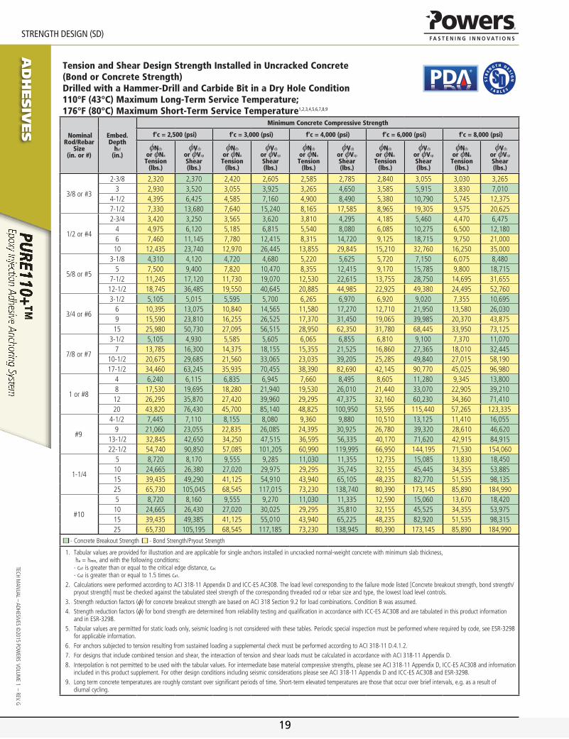
Tension and Shear Design Strength Installed in Uncracked Concrete(Bond or Concrete Strength)Drilled with a Hammer-Drill and Carbide Bit in a Dry Hole Condition110°F (43°C) Maximum Long-Term Service Temperature; 176°F (80°C) Maximum Short-Term Service Temperature1,2,3,4,5,6,7,8,9
®
Nominal Rod/Rebar
Size(in. or #)
Embed.Depth
hef
(in.)
Minimum Concrete Compressive Strength
f'c = 2,500 (psi) f'c = 3,000 (psi) f'c = 4,000 (psi) f'c = 6,000 (psi) f'c = 8,000 (psi)
φNcb
or φNa
Tension(lbs.)
φVcb
or φVcp
Shear(lbs.)
φNcb
or φNa
Tension(lbs.)
φVcb
or φVcp
Shear(lbs.)
φNcb
or φNa
Tension(lbs.)
φVcb
or φVcp
Shear(lbs.)
φNcb
or φNa
Tension(lbs.)
φVcb
or φVcp
Shear(lbs.)
φNcb
or φNa
Tension(lbs.)
φVcb
or φVcp
Shear(lbs.)
3/8 or #3
2-3/8 2,320 2,370 2,420 2,605 2,585 2,785 2,840 3,055 3,030 3,2653 2,930 3,520 3,055 3,925 3,265 4,650 3,585 5,915 3,830 7,010
4-1/2 4,395 6,425 4,585 7,160 4,900 8,490 5,380 10,790 5,745 12,3757-1/2 7,330 13,680 7,640 15,240 8,165 17,585 8,965 19,305 9,575 20,625
1/2 or #4
2-3/4 3,420 3,250 3,565 3,620 3,810 4,295 4,185 5,460 4,470 6,4754 4,975 6,120 5,185 6,815 5,540 8,080 6,085 10,275 6,500 12,1806 7,460 11,145 7,780 12,415 8,315 14,720 9,125 18,715 9,750 21,00010 12,435 23,740 12,970 26,445 13,855 29,845 15,210 32,760 16,250 35,000
5/8 or #5
3-1/8 4,310 4,120 4,720 4,680 5,220 5,625 5,720 7,150 6,075 8,4805 7,500 9,400 7,820 10,470 8,355 12,415 9,170 15,785 9,800 18,715
7-1/2 11,245 17,120 11,730 19,070 12,530 22,615 13,755 28,750 14,695 31,65512-1/2 18,745 36,485 19,550 40,645 20,885 44,985 22,925 49,380 24,495 52,760
3/4 or #6
3-1/2 5,105 5,015 5,595 5,700 6,265 6,970 6,920 9,020 7,355 10,6956 10,395 13,075 10,840 14,565 11,580 17,270 12,710 21,950 13,580 26,0309 15,590 23,810 16,255 26,525 17,370 31,450 19,065 39,985 20,370 43,87515 25,980 50,730 27,095 56,515 28,950 62,350 31,780 68,445 33,950 73,125
7/8 or #7
3-1/2 5,105 4,930 5,585 5,605 6,065 6,855 6,810 9,100 7,370 11,0707 13,785 16,300 14,375 18,155 15,355 21,525 16,860 27,365 18,010 32,445
10-1/2 20,675 29,685 21,560 33,065 23,035 39,205 25,285 49,840 27,015 58,19017-1/2 34,460 63,245 35,935 70,455 38,390 82,690 42,145 90,770 45,025 96,980
1 or #8
4 6,240 6,115 6,835 6,945 7,660 8,495 8,605 11,280 9,345 13,8008 17,530 19,695 18,280 21,940 19,530 26,010 21,440 33,070 22,905 39,21012 26,295 35,870 27,420 39,960 29,295 47,375 32,160 60,230 34,360 71,41020 43,820 76,430 45,700 85,140 48,825 100,950 53,595 115,440 57,265 123,335
#9
4-1/2 7,445 7,110 8,155 8,080 9,360 9,880 10,510 13,125 11,410 16,0559 21,060 23,055 22,835 26,085 24,395 30,925 26,780 39,320 28,610 46,620
13-1/2 32,845 42,650 34,250 47,515 36,595 56,335 40,170 71,620 42,915 84,91522-1/2 54,740 90,850 57,085 101,205 60,990 119,995 66,950 144,195 71,530 154,060
1-1/4
5 8,720 8,170 9,555 9,285 11,030 11,355 12,735 15,085 13,830 18,45010 24,665 26,380 27,020 29,975 29,295 35,745 32,155 45,445 34,355 53,88515 39,435 49,290 41,125 54,910 43,940 65,105 48,235 82,770 51,535 98,13525 65,730 105,045 68,545 117,015 73,230 138,740 80,390 173,145 85,890 184,990
#10
5 8,720 8,160 9,555 9,270 11,030 11,335 12,590 15,060 13,670 18,42010 24,665 26,430 27,020 30,025 29,295 35,810 32,155 45,525 34,355 53,97515 39,435 49,385 41,125 55,010 43,940 65,225 48,235 82,920 51,535 98,31525 65,730 105,195 68,545 117,185 73,230 138,945 80,390 173,145 85,890 184,990
-ConcreteBreakoutStrength -BondStrength/PryoutStrength
1. Tabularvaluesareprovidedforillustrationandareapplicableforsingleanchorsinstalledinuncrackednormal-weightconcretewithminimumslabthickness,ha=hmin,andwiththefollowingconditions:-ca1isgreaterthanorequaltothecriticaledgedistance,cac-ca2isgreaterthanorequalto1.5timesca1.
2. CalculationswereperformedaccordingtoACI318-11AppendixDandICC-ESAC308.Theloadlevelcorrespondingtothefailuremodelisted[Concretebreakoutstrength,bondstrength/pryoutstrength]mustbecheckedagainstthetabulatedsteelstrengthofthecorrespondingthreadedrodorrebarsizeandtype,thelowestloadlevelcontrols.
3. Strengthreductionfactors(φ)forconcretebreakoutstrengtharebasedonACI318Section9.2forloadcombinations.ConditionBwasassumed.4. Strengthreductionfactors(φ)forbondstrengtharedeterminedfromreliabilitytestingandqualificationinaccordancewithICC-ESAC308andaretabulatedinthisproductinformation
andinESR-3298.5. Tabularvaluesarepermittedforstaticloadsonly,seismicloadingisnotconsideredwiththesetables.Periodicspecialinspectionmustbeperformedwhererequiredbycode,seeESR-3298
forapplicableinformation.6. ForanchorssubjectedtotensionresultingfromsustainedloadingasupplementalcheckmustbeperformedaccordingtoACI318-11D.4.1.2.7. Fordesignsthatincludecombinedtensionandshear,theinteractionoftensionandshearloadsmustbecalculatedinaccordancewithACI318-11AppendixD.8. Interpolationisnotpermittedtobeusedwiththetabularvalues.Forintermediatebasematerialcompressivestrengths,pleaseseeACI318-11AppendixD,ICC-ESAC308andinformation
includedinthisproductsupplement.ForotherdesignconditionsincludingseismicconsiderationspleaseseeACI318-11AppendixDandICC-ESAC308andESR-3298.9. Longtermconcretetemperaturesareroughlyconstantoversignificantperiodsoftime.Short-termelevatedtemperaturesarethosethatoccuroverbriefintervals,e.g.asaresultof
diurnalcycling.
19

www.powers.com 14
Ad
hesiv
es
StrenGth DeSIGn (SD)
TECH
MAN
UAL
– Ad
HEsi
vEs
©20
15 P
OW
ERs
vO
LUM
E 1
– R
Ev. g
Tension and Shear Design Strength Installed in Cracked Concrete (Bond or Concrete Strength)Drilled with a Hammer-Drill and Carbide Bit in a Dry Hole Condition75°F (24°C) Maximum Long-Term Service Temperature; 104°F (40°C) Maximum Short-Term Service Temperature1,2,3,4,5,6,7,8
Nominal Rod/Rebar
Size(in. or #)
Embed.Depth
hef
(in.)
Minimum Concrete Compressive Strength
f'c = 2,500 (psi) f'c = 3,000 (psi) f'c = 4,000 (psi) f'c = 6,000 (psi) f'c = 8,000 (psi)
φNcb
or φNa
Tension(lbs.)
φVcb
or φVcp
Shear(lbs.)
φNcb
or φNa
Tension(lbs.)
φVcb
or φVcp
Shear(lbs.)
φNcb
or φNa
Tension(lbs.)
φVcb
or φVcp
Shear(lbs.)
φNcb
or φNa
Tension(lbs.)
φVcb
or φVcp
Shear(lbs.)
φNcb
or φNa
Tension(lbs.)
φVcb
or φVcp
Shear(lbs.)
3/8 or #3
2-3/8 1,800 1,835 1,880 2,020 2,005 2,160 2,200 2,370 2,355 2,5353 2,275 2,860 2,370 3,185 2,535 3,775 2,780 4,800 2,970 5,690
4-1/2 3,410 5,215 3,560 5,810 3,800 6,890 4,170 8,760 4,460 9,6007-1/2 5,685 11,100 5,930 12,370 6,335 13,645 6,955 14,980 7,430 16,005
1/2 or #4
2-3/4 2,520 2,360 2,760 2,680 3,095 3,280 3,400 4,355 3,630 5,2454 4,045 4,785 4,215 5,435 4,505 6,545 4,945 8,320 5,285 9,8706 6,065 9,030 6,325 10,060 6,755 11,925 7,420 15,160 7,925 17,07010 10,110 19,230 10,540 21,420 11,260 24,255 12,365 26,630 13,210 28,450
5/8 or #5
3-1/8 3,050 2,940 3,345 3,340 3,850 4,085 4,335 5,430 4,720 6,6405 6,120 7,135 6,380 8,105 6,820 9,910 7,485 12,770 7,995 15,140
7-1/2 9,180 13,850 9,575 15,430 10,230 18,295 11,225 23,255 11,995 25,83512-1/2 15,300 29,515 15,955 32,880 17,045 36,715 18,710 40,305 19,990 43,060
3/4 or #6
3-1/2 3,620 3,580 3,965 4,070 4,575 4,980 5,325 6,610 5,790 8,0856 8,120 9,710 8,895 11,035 9,820 13,495 10,780 17,800 11,515 21,1059 13,220 19,185 13,785 21,510 14,730 25,505 16,165 32,420 17,275 37,20515 22,030 41,135 22,975 45,825 24,545 52,870 26,945 58,035 28,790 62,005
7/8 or #7
3-1/2 3,620 3,525 3,965 4,000 4,575 4,895 5,360 6,500 5,810 7,9507 10,230 11,860 11,210 13,475 12,945 16,485 14,670 21,895 15,675 26,300
10-1/2 17,990 23,430 18,765 26,620 20,045 31,780 22,005 40,405 23,510 47,90517-1/2 29,985 51,270 31,270 57,110 33,410 67,715 36,675 78,995 39,185 84,395
1 or #8
4 4,420 4,365 4,840 4,960 5,590 6,065 6,655 8,060 7,215 9,8558 12,500 14,105 13,695 16,025 15,815 19,600 18,340 26,035 19,595 31,82512 22,495 27,860 23,460 31,655 25,065 38,455 27,515 48,885 29,395 57,96520 37,490 62,035 39,095 69,110 41,770 81,940 45,855 98,765 48,990 105,520
#9
4-1/2 5,275 5,080 5,780 5,770 6,670 7,060 7,620 9,375 8,260 11,4659 14,920 16,465 16,340 18,710 18,870 22,880 21,395 30,390 22,855 37,170
13-1/2 26,235 32,530 27,360 36,955 29,235 45,200 32,090 57,945 34,285 68,70022-1/2 43,730 73,505 45,600 81,880 48,720 97,085 53,485 115,195 57,140 123,075
1-1/4
5 6,175 5,835 6,765 6,630 7,815 8,110 9,465 10,775 10,260 13,17510 17,470 18,845 19,140 21,410 22,100 26,185 26,410 34,780 28,220 42,54015 32,095 37,220 33,780 42,285 36,090 51,720 39,615 67,225 42,325 79,70525 53,985 85,315 56,300 95,035 60,150 112,685 66,030 142,215 70,545 151,945
#10
5 6,175 5,830 6,765 6,620 7,815 8,100 9,365 10,755 10,150 13,15510 17,470 18,880 19,140 21,445 22,100 26,230 26,410 34,840 28,220 42,61515 32,095 37,290 33,780 42,365 36,090 51,815 39,615 67,345 42,325 79,85025 53,985 85,440 56,300 95,175 60,150 112,850 66,030 142,215 70,545 151,945
-ConcreteBreakoutStrength -BondStrength/PryoutStrength
1. Tabularvaluesareprovidedforillustrationandareapplicableforsingleanchorsinstalledincrackednormal-weightconcretewithminimumslabthickness,ha=hmin,andwiththefollowingconditions:-ca1isgreaterthanorequaltothecriticaledgedistance,cac-ca2isgreaterthanorequalto1.5timesca1.
2. CalculationswereperformedfollowingmethodologyinACI318-11AppendixDandICC-ESAC308.Theloadlevelcorrespondingtothefailuremodelisted[Concretebreakoutstrength,bondstrength/pryoutstrength]mustbecheckedagainstthetabulatedsteelstrengthofthecorrespondingthreadedrodorrebarsizeandtype,thelowestloadlevelcontrols.This temperature range is not recognized by ACI 318-11 and does not meet the minimum temperature requirements from ACI 355.4 Table 8.1 and consequently is not applicable to design under ACI 318-11 or current and past editions of the International Building Code (IBC). The tabulated values are provided for analysis and evaluation of existing conditions only.
3. Strengthreductionfactors(φ)forconcretebreakoutstrengtharebasedonACI318Section9.2forloadcombinations.ConditionBwasassumed.4. Strengthreductionfactors(φ)forbondstrengtharedeterminedfromreliabilitytestingandqualificationinaccordancewithICC-ESAC308andaretabulatedinthisproductinformation
andinESR-3298.5. Tabularvaluesarepermittedforshort-termstaticloadsonly,seismicloadingisnotconsideredwiththesetables.6. Fordesignsthatincludecombinedtensionandshear,theinteractionoftensionandshearloadsmustbecalculatedinaccordancewithACI318-11AppendixD.7. Interpolationisnotpermittedtobeusedwiththetabularvalues.Forintermediatebasematerialcompressivestrengths,pleaseseeACI318-11AppendixD,ICC-ESAC308andinformation
includedinthisproductsupplement.ForotherdesignconditionsincludingseismicconsiderationspleaseseeACI318-11AppendixDandICC-ESAC308andESR-3298.8. Longtermconcretetemperaturesareroughlyconstantoversignificantperiodsoftime.Short-termelevatedtemperaturesarethosethatoccuroverbriefintervals,e.g.asaresultof
diurnalcycling.
20

Ad
hesiv
es
www.powers.com 15
TECH MAN
UAL – AdHEsivEs ©2015 PO
WERs vO
LUME 1 – REv. g
StrenGth DeSIGn (SD)
Tension and Shear Design Strength Installed in Cracked Concrete(Bond or Concrete Strength)Drilled with a Hammer-Drill and Carbide Bit in a Dry Hole Condition110°F (43°C) Maximum Long-Term Service Temperature; 140°F (60°C) Maximum Short-Term Service Temperature1,2,3,4,5,6,7,8,9
®
Nominal Rod/Rebar
Size(in. or #)
Embed.Depth
hef
(in.)
Minimum Concrete Compressive Strength
f'c = 2,500 (psi) f'c = 3,000 (psi) f'c = 4,000 (psi) f'c = 6,000 (psi) f'c = 8,000 (psi)
φNcb
or φNa
Tension(lbs.)
φVcb
or φVcp
Shear(lbs.)
φNcb
or φNa
Tension(lbs.)
φVcb
or φVcp
Shear(lbs.)
φNcb
or φNa
Tension(lbs.)
φVcb
or φVcp
Shear(lbs.)
φNcb
or φNa
Tension(lbs.)
φVcb
or φVcp
Shear(lbs.)
φNcb
or φNa
Tension(lbs.)
φVcb
or φVcp
Shear(lbs.)
3/8 or #3
2-3/8 1,800 1,835 1,880 2,020 2,005 2,160 2,200 2,370 2,355 2,5353 2,275 2,860 2,370 3,185 2,535 3,775 2,780 4,800 2,970 5,690
4-1/2 3,410 5,215 3,560 5,810 3,800 6,890 4,170 8,760 4,460 9,6007-1/2 5,685 11,100 5,930 12,370 6,335 13,645 6,955 14,980 7,430 16,005
1/2 or #4
2-3/4 2,520 2,360 2,760 2,680 3,095 3,280 3,400 4,355 3,630 5,2454 4,045 4,785 4,215 5,435 4,505 6,545 4,945 8,320 5,285 9,8706 6,065 9,030 6,325 10,060 6,755 11,925 7,420 15,160 7,925 17,07010 10,110 19,230 10,540 21,420 11,260 24,255 12,365 26,630 13,210 28,450
5/8 or #5
3-1/8 3,050 2,940 3,345 3,340 3,850 4,085 4,335 5,430 4,720 6,6405 6,120 7,135 6,380 8,105 6,820 9,910 7,485 12,770 7,995 15,140
7-1/2 9,180 13,850 9,575 15,430 10,230 18,295 11,225 23,255 11,995 25,83512-1/2 15,300 29,515 15,955 32,880 17,045 36,715 18,710 40,305 19,990 43,060
3/4 or #6
3-1/2 3,620 3,580 3,965 4,070 4,575 4,980 5,325 6,610 5,790 8,0856 8,120 9,710 8,895 11,035 9,820 13,495 10,780 17,800 11,515 21,1059 13,220 19,185 13,785 21,510 14,730 25,505 16,165 32,420 17,275 37,20515 22,030 41,135 22,975 45,825 24,545 52,870 26,945 58,035 28,790 62,005
7/8 or #7
3-1/2 3,620 3,525 3,965 4,000 4,575 4,895 5,360 6,500 5,810 7,9507 10,230 11,860 11,210 13,475 12,945 16,485 14,670 21,895 15,675 26,300
10-1/2 17,990 23,430 18,765 26,620 20,045 31,780 22,005 40,405 23,510 47,90517-1/2 29,985 51,270 31,270 57,110 33,410 67,715 36,675 78,995 39,185 84,395
1 or #8
4 4,420 4,365 4,840 4,960 5,590 6,065 6,655 8,060 7,215 9,8558 12,500 14,105 13,695 16,025 15,815 19,600 18,340 26,035 19,595 31,82512 22,495 27,860 23,460 31,655 25,065 38,455 27,515 48,885 29,395 57,96520 37,490 62,035 39,095 69,110 41,770 81,940 45,855 98,765 48,990 105,520
#9
4-1/2 5,275 5,080 5,780 5,770 6,670 7,060 7,620 9,375 8,260 11,4659 14,920 16,465 16,340 18,710 18,870 22,880 21,395 30,390 22,855 37,170
13-1/2 26,235 32,530 27,360 36,955 29,235 45,200 32,090 57,945 34,285 68,70022-1/2 43,730 73,505 45,600 81,880 48,720 97,085 53,485 115,195 57,140 123,075
1-1/4
5 6,175 5,835 6,765 6,630 7,815 8,110 9,465 10,775 10,260 13,17510 17,470 18,845 19,140 21,410 22,100 26,185 26,410 34,780 28,220 42,54015 32,095 37,220 33,780 42,285 36,090 51,720 39,615 67,225 42,325 79,70525 53,985 85,315 56,300 95,035 60,150 112,685 66,030 142,215 70,545 151,945
#10
5 6,175 5,830 6,765 6,620 7,815 8,100 9,365 10,755 10,150 13,15510 17,470 18,880 19,140 21,445 22,100 26,230 26,410 34,840 28,220 42,61515 32,095 37,290 33,780 42,365 36,090 51,815 39,615 67,345 42,325 79,85025 53,985 85,440 56,300 95,175 60,150 112,850 66,030 142,215 70,545 151,945
-ConcreteBreakoutStrength -BondStrength/PryoutStrength
1. Tabularvaluesareprovidedforillustrationandareapplicableforsingleanchorsinstalledincrackednormal-weightconcretewithminimumslabthickness,ha=hmin,andwiththefollowingconditions:-ca1isgreaterthanorequaltothecriticaledgedistance,cac-ca2isgreaterthanorequalto1.5timesca1.
2. CalculationswereperformedaccordingtoACI318-11AppendixDandICC-ESAC308.Theloadlevelcorrespondingtothefailuremodelisted[Concretebreakoutstrength,bondstrength/pryoutstrength]mustbecheckedagainstthetabulatedsteelstrengthofthecorrespondingthreadedrodorrebarsizeandtype,thelowestloadlevelcontrols.
3. Strengthreductionfactors(φ)forconcretebreakoutstrengtharebasedonACI318Section9.2forloadcombinations.ConditionBwasassumed.4. Strengthreductionfactors(φ)forbondstrengtharedeterminedfromreliabilitytestingandqualificationinaccordancewithICC-ESAC308andaretabulatedinthisproductinformation
andinESR-3298.5. Tabularvaluesarepermittedforstaticloadsonly,seismicloadingisnotconsideredwiththesetables.Periodicspecialinspectionmustbeperformedwhererequiredbycode,seeESR-3298
forapplicableinformation.6. ForanchorssubjectedtotensionresultingfromsustainedloadingasupplementalcheckmustbeperformedaccordingtoACI318-11D.4.1.2.7. Fordesignsthatincludecombinedtensionandshear,theinteractionoftensionandshearloadsmustbecalculatedinaccordancewithACI318-11AppendixD.8. Interpolationisnotpermittedtobeusedwiththetabularvalues.Forintermediatebasematerialcompressivestrengths,pleaseseeACI318-11AppendixD,ICC-ESAC308andinformation
includedinthisproductsupplement.ForotherdesignconditionsincludingseismicconsiderationspleaseseeACI318-11AppendixDandICC-ESAC308andESR-3298.9. Longtermconcretetemperaturesareroughlyconstantoversignificantperiodsoftime.Short-termelevatedtemperaturesarethosethatoccuroverbriefintervals,e.g.asaresultof
diurnalcycling.
21

www.powers.com 16
Ad
hesiv
es
StrenGth DeSIGn (SD)
TECH
MAN
UAL
– Ad
HEsi
vEs
©20
15 P
OW
ERs
vO
LUM
E 1
– R
Ev. g
Tension and Shear Design Strength Installed in Cracked Concrete(Bond or Concrete Strength)Drilled with a Hammer-Drill and Carbide Bit in a Dry Hole Condition110°F (43°C) Maximum Long-Term Service Temperature; 176°F (80°C) Maximum Short-Term Service Temperature1,2,3,4,5,6,7,8,9
®
Nominal Rod/Rebar
Size(in. or #)
Embed.Depth
hef
(in.)
Minimum Concrete Compressive Strength
f'c = 2,500 (psi) f'c = 3,000 (psi) f'c = 4,000 (psi) f'c = 6,000 (psi) f'c = 8,000 (psi)
φNcb
or φNa
Tension(lbs.)
φVcb
or φVcp
Shear(lbs.)
φNcb
or φNa
Tension(lbs.)
φVcb
or φVcp
Shear(lbs.)
φNcb
or φNa
Tension(lbs.)
φVcb
or φVcp
Shear(lbs.)
φNcb
or φNa
Tension(lbs.)
φVcb
or φVcp
Shear(lbs.)
φNcb
or φNa
Tension(lbs.)
φVcb
or φVcp
Shear(lbs.)
3/8 or #3
2-3/8 1,320 1,420 1,375 1,480 1,470 1,580 1,615 1,735 1,725 1,8553 1,665 2,515 1,735 2,800 1,855 3,320 2,035 4,225 2,175 4,690
4-1/2 2,500 4,590 2,605 5,115 2,785 5,995 3,055 6,580 3,265 7,0307-1/2 4,165 8,970 4,340 9,350 4,640 9,990 5,095 10,970 5,440 11,720
1/2 or #4
2-3/4 2,035 2,325 2,125 2,585 2,270 3,070 2,490 3,900 2,660 4,6254 2,960 4,370 3,090 4,870 3,300 5,775 3,620 7,340 3,870 8,3356 4,440 7,960 4,630 8,870 4,950 10,515 5,430 11,700 5,805 12,50010 7,400 15,945 7,720 16,625 8,245 17,765 9,055 19,500 9,675 20,835
5/8 or #5
3-1/8 2,740 2,940 2,895 3,340 3,095 4,015 3,385 5,105 3,600 6,0555 4,440 6,715 4,630 7,480 4,950 8,870 5,430 11,275 5,805 12,500
7-1/2 6,660 12,230 6,945 13,625 7,425 15,985 8,150 17,550 8,705 18,75012-1/2 11,105 23,915 11,580 24,940 12,370 26,645 13,580 29,250 14,510 31,250
3/4 or #6
3-1/2 3,360 3,580 3,540 4,070 3,855 4,980 4,260 6,440 4,525 7,6406 6,395 9,340 6,670 10,405 7,125 12,335 7,820 15,680 8,355 18,0009 9,595 17,010 10,005 18,945 10,690 22,465 11,735 25,270 12,535 27,00015 15,990 34,440 16,675 35,915 17,815 38,370 19,555 42,120 20,895 45,000
7/8 or #7
3-1/2 3,350 3,525 3,530 4,000 3,830 4,895 4,300 6,500 4,655 7,9057 8,705 11,640 9,080 12,970 9,700 15,375 10,645 19,545 11,375 23,175
10-1/2 13,060 21,200 13,615 23,620 14,550 28,005 15,970 34,400 17,065 36,75017-1/2 21,765 45,175 22,695 48,880 24,245 52,225 26,615 57,330 28,440 61,250
1 or #8
4 4,165 4,365 4,390 4,960 4,760 6,065 5,350 8,060 5,810 9,8558 10,895 14,065 11,365 15,670 12,140 18,580 13,325 23,620 14,240 28,00512 16,345 25,620 17,045 28,540 18,210 33,840 19,990 43,020 21,360 46,00020 27,240 54,595 28,405 60,815 30,350 65,370 33,315 71,760 35,595 76,670
#9
4-1/2 4,830 5,080 5,085 5,770 5,515 7,060 6,190 9,375 6,720 11,4659 12,900 16,465 13,455 18,630 14,375 22,090 15,780 28,085 16,860 33,300
13-1/2 19,350 30,465 20,180 33,940 21,560 40,240 23,670 50,980 25,290 54,46522-1/2 32,255 64,895 33,635 72,290 35,935 77,400 39,450 84,965 42,145 90,780
1-1/4
5 6,015 5,835 6,335 6,630 6,875 8,110 7,715 10,775 8,380 13,17510 15,930 18,845 16,610 21,410 17,745 25,535 19,480 32,460 20,815 38,49015 23,890 35,210 24,915 39,220 26,620 46,505 29,220 59,120 31,220 67,24525 39,820 75,030 41,525 83,580 44,365 95,555 48,700 104,895 52,035 112,070
#10
5 5,950 5,830 6,265 6,620 6,795 8,100 7,630 10,755 8,280 13,15510 15,930 18,880 16,610 21,445 17,745 25,580 19,480 32,520 20,815 38,55515 23,890 35,275 24,915 39,295 26,620 46,590 29,220 59,230 31,220 67,24525 39,820 75,140 41,525 83,705 44,365 95,555 48,700 104,895 52,035 112,070
-ConcreteBreakoutStrength -BondStrength/PryoutStrength
1. Tabularvaluesareprovidedforillustrationandareapplicableforsingleanchorsinstalledincrackednormal-weightconcretewithminimumslabthickness,ha=hmin,andwiththefollowingconditions:-ca1isgreaterthanorequaltothecriticaledgedistance,cac-ca2isgreaterthanorequalto1.5timesca1.
2. CalculationswereperformedaccordingtoACI318-11AppendixDandICC-ESAC308.Theloadlevelcorrespondingtothefailuremodelisted[Concretebreakoutstrength,bondstrength/pryoutstrength]mustbecheckedagainstthetabulatedsteelstrengthofthecorrespondingthreadedrodorrebarsizeandtype,thelowestloadlevelcontrols.
3. Strengthreductionfactors(φ)forconcretebreakoutstrengtharebasedonACI318Section9.2forloadcombinations.ConditionBwasassumed.4. Strengthreductionfactors(φ)forbondstrengtharedeterminedfromreliabilitytestingandqualificationinaccordancewithICC-ESAC308andaretabulatedinthisproductinformation
andinESR-3298.5. Tabularvaluesarepermittedforstaticloadsonly,seismicloadingisnotconsideredwiththesetables.Periodicspecialinspectionmustbeperformedwhererequiredbycode,seeESR-3298
forapplicableinformation.6. ForanchorssubjectedtotensionresultingfromsustainedloadingasupplementalcheckmustbeperformedaccordingtoACI318-11D.4.1.2.7. Fordesignsthatincludecombinedtensionandshear,theinteractionoftensionandshearloadsmustbecalculatedinaccordancewithACI318-11AppendixD.8. Interpolationisnotpermittedtobeusedwiththetabularvalues.Forintermediatebasematerialcompressivestrengths,pleaseseeACI318-11AppendixD,ICC-ESAC308andinformation
includedinthisproductsupplement.ForotherdesignconditionsincludingseismicconsiderationspleaseseeACI318-11AppendixDandICC-ESAC308andESR-3298.9. Longtermconcretetemperaturesareroughlyconstantoversignificantperiodsoftime.Short-termelevatedtemperaturesarethosethatoccuroverbriefintervals,e.g.asaresultof
diurnalcycling.
22

Ad
hesiv
es
www.powers.com 17
TECH MAN
UAL – AdHEsivEs ©2015 PO
WERs vO
LUME 1 – REv. g
StrenGth DeSIGn (SD)
Tension Design of Steel Elements (Steel Strength)1,2
®
Steel Elements - Threaded Rod and Reinforcing Bar
Nominal Rod/Rebar
Size(in. or No.)
ASTM A36 and
ASTM F1554
Grade 36
ASTM F1554
Grade 55
ASTM A193 Grade B7 and ASTM F1554 Grade
105
ASTM A449
ASTM F568M
Class 5.8 and ISO 898-1
Class 5.8
ASTM F593 CW Stainless
(Types 304 and
316)
ASTM A193 Grade
B8/B8M, Class 1
Stainless (Types
304 and 316)
ASTM A193 Grade
B8/B8M2, Class 2B Stainless
(Types 304 and
316)
ASTM A615
Grade 75 Rebar
ASTM A615
Grade 60 Rebar
ASTM A706
Grade 60 Rebar
ASTM A615
Grade 40 Rebar
ØNsa
Tension(lbs.)
ØNsa
Tension(lbs.)
ØNsa
Tension(lbs.)
ØNsa
Tension(lbs.)
ØNsa
Tension(lbs.)
ØNsa
Tension(lbs.)
ØNsa
Tension(lbs.)
ØNsa
Tension(lbs.)
ØNsa
Tension(lbs.)
ØNsa
Tension(lbs.)
ØNsa
Tension(lbs.)
ØNsa
Tension(lbs.)
3/8 or #3 3,370 4,360 7,265 6,975 3,655 5,040 3,315 5,525 7,150 7,425 6,600 4,950
1/2 or #4 6,175 7,980 13,300 12,770 6,690 9,225 6,070 10,110 13,000 13,500 12,000 9,000
5/8 or #5 9,835 12,715 21,190 20,340 10,650 14,690 9,660 16,105 20,150 20,925 18,600 13,950
3/4 or #6 14,550 18,815 31,360 30,105 15,765 18,480 14,300 23,830 28,600 29,700 26,400 19,800
7/8 or #7 20,085 25,970 43,285 41,930 21,760 25,510 19,735 32,895 39,000 40,500 36,000 -
1 or #8 26,350 34,070 56,785 54,515 28,545 33,465 25,895 43,160 51,350 53,325 47,400 -
#9 - - - - - - - - 65,000 67,500 60,000 -
1-1/4 or #10 42,160 54,510 9,100 76,315 - 53,540 41,430 69,050 82,550 85,725 76,200 -
-SteelStrength
1. SteeltensiledesignstrengthaccordingtoACI318AppendixD,φNsa=φ •Ase,n •futa
2. Thetabulatedsteeldesignstrengthintensionmustbecheckedagainstthebondstrength/concretecapacitydesignstrengthtodeterminethecontrollingfailuremode,thelowestloadlevelcontrols.
Shear Design of Steel Elements (Steel Strength)1,2
Steel Elements - Threaded Rod and Reinforcing Bar
Nominal Rod/Rebar
Size(in. or No.)
ASTM A36 and
ASTM F1554
Grade 36
ASTM F1554
Grade 55
ASTM A193 Grade B7 and ASTM F1554 Grade
105
ASTM A449
ASTM F568M
Class 5.8 and ISO 898-1
Class 5.8
ASTM F593 CW Stainless
(Types 304 and
316)
ASTM A193 Grade
B8/B8M, Class 1
Stainless (Types
304 and 316)
ASTM A193 Grade
B8/B8M2, Class 2B Stainless
(Types 304 and
316)
ASTM A615
Grade 75 Rebar
ASTM A615
Grade 60 Rebar
ASTM A706
Grade 60 Rebar
ASTM A615
Grade 40 Rebar
ØVsa
Shear(lbs.)
ØVsa
Shear(lbs.)
ØVsa
Shear(lbs.)
ØVsa
Shear(lbs.)
ØVsa
Shear(lbs.)
ØVsa
Shear(lbs.)
ØVsa
Shear(lbs.)
ØVsa
Shear(lbs.)
ØVsa
Shear(lbs.)
ØVsa
Shear(lbs.)
ØVsa
Shear(lbs.)
ØVsa
Shear(lbs.)
3/8 or #3 1,755 2,265 3,775 3,625 2,025 2,790 1,725 2,870 3,960 3,860 3,430 2,575
1/2 or #4 3,210 4,150 6,915 6,640 3,705 5,110 3,155 5,255 7,200 7,020 6,240 4,680
5/8 or #5 5,115 6,610 11,020 10,575 5,900 8,135 5,025 8,375 11,160 10,880 9,670 7,255
3/4 or #6 7,565 9,785 16,305 15,655 8,730 10,235 7,435 12,390 15,840 15,445 13,730 10,295
7/8 or #7 10,445 13,505 22,505 21,805 12,050 14,130 10,265 17,105 21,600 21,060 18,720 -
1 or #8 13,700 17,715 29,525 28,345 15,810 18,535 13,465 22,445 28,440 27,730 24,650 -
#9 - - - - - - - - 36,000 35,100 31,200 -
1-1/4 or #10 21,920 28,345 4,735 39,685 - 29,655 21,545 35,905 45,720 44,575 39,625 -
-SteelStrength
1. SteelsheardesignstrengthaccordingtoACI318AppendixD,φVsa=φ •0.60•Ase,V •futa
2. Thetabulatedsteeldesignstrengthinshearmustbecheckedagainstthebondstrength/concretecapacitydesignstrengthtodeterminethecontrollingfailuremode,thelowestloadlevelcontrols.
23

www.powers.com 22
Ad
hesiv
es
orDerInG InformatIon
TECH
MAN
UAL
– Ad
HEsi
vEs
©20
15 P
OW
ERs
vO
LUM
E 1
– R
Ev. g
ordering inforMation
Pure110+ CartridgesCat. No. Description Std. Box Std. Ctn. Pallet
08310sd Pure110+ 9 fl. oz. Quik-shot cartridge (1:1 mix ratio) 12 24 432
08321sd Pure110+ 21 fl. oz. dual cartridge (1:1 mix ratio) 12 - 540
08313sd Pure110+ 13 fl. oz. dual cartridge (3:1 mix ratio) 12 - 540
08320sd Pure110+ 20 fl. oz. dual cartridge (3:1 mix ratio) 12 - 540
OnePure110+mixingnozzleispackagedwitheachcartridge.Pure110+mixingnozzlesmustbeusedtoensurecompleteandpropermixingoftheadhesive.
Cartridge System Mixing NozzlesCat. No. Description Std. Pkg. Std. Ctn.
08294 Extra mixing nozzle (with 8" extension) for Pure110+ Quik-shot 2 24
08281 Mixing nozzle extension, 8" long 2 24
08297 Mixing nozzle extension, 20" long 1 12
08609 Extra high flow mixing nozzle (with 8" extension) for Pure110+ dual cartridge 2 24
Dispensing Tools for Injection AdhesiveCat. No. Description Std. Box Std. Ctn.
08437 Manual caulking gun for Quik-shot 1 12
08479 High performance caulking gun for Quik-shot 1 12
08409 21 fl. oz. standard metal manual tool 1 10
08421 21 fl. oz. High performance manual tool 1 10
08442 21 fl. oz. Battery powered tool (cordless) 1 -
08413 21 fl. oz. Pneumatic tool 1 -
08298 13 fl. oz. + 20 fl. oz. manual tool (3:1 mix ratio) 1 6
08279sd 13 fl. oz + 20 fl. oz. Battery powered tool (3:1 mix ratio) 1 -
08497sd 13 fl. oz. + 20 fl. oz Pneumatic tool (3:1 mix ratio) 1 6
08442 08479
08409 08421
08413 08437
Hole Cleaning Tools and AccessoriesCat No. Description Std. Box
08284 Wire brush for 7/16”ANsi hole(3/8” rod or #3 rebar), 6-3/4” length 1
08285 Wire brush for 9/16”ANsi hole(1/2” rod or #4 rebar), 6-3/4” length 1
08275 Wire brush for 5/8" ANsi hole(#4 rebar), 6-3/4" length 1
08286 Wire brush for 11/16”ANsi hole (5/8” rod or #5 rebar), 7-7/8” length 1
08278 Wire brush for 3/4”ANsi hole(5/8” rod or #5 rebar), 7-7/8” length 1
08287 Wire brush for 7/8”ANsi hole(3/4” rod or #6 rebar), 7-7/8” length 1
08288 Wire brush for 1”ANsi hole(7/8” rod or #7 rebar), 11-7/8” length 1
08289 Wire brush for 1-1/8”ANsi hole(1” rod or #8 rebar), 11-7/8” length 1
08290 Wire brush for 1-3/8”ANsi hole(1-1/4” rod or #9 rebar), 11-7/8” length 1
08291 Wire brush for 1-1/2”ANsi hole(#10 rebar), 11-7/8” length 1
08283 sds-plus adapter for steel brushes 1
08296 standard drill adapter for steel brushes(e.g. Jacobs Chuck) 1
08282 steel brush extension, 12” length 108292 Air compressor nozzle with extension, 18” length 1
08465 Adjustable torque wrench with 1/2” square drive (10 to 150 ft.-lbs.) 1
08466 Adjustable torque wrench with 1/2” square drive (25 to 250 ft.-lbs.) 1
Adhesive Piston Plugs
Cat. # Description ANSI Drill Bit Dia.
Threaded Rod Dia.
Reinforcing Bar Size
Std.Bag"
08302 9/16" Plug 9/16" 1/2" #4 10
08304 5/8" Plug 5/8" - #4 10
08258 11/16" Plug 11/16" 5/8" #5 10
08259 3/4" Plug 3/4" 5/8" #5 10
08300 7/8" Plug 7/8" 3/4" #6 10
08301 1" Plug 1" 7/8" #7 10
08303 1-1/8" Plug 1-1/8" 1" #8 10
08305 1-3/8" Plug 1-3/8" 1-1/4" #9 10
08309 1-1/2" Plug 1-1/2" - #10 10
Plastic Screen Tubes
Cat.No. Description ANSI Drill Diameter
Standard Carton
08310 3/8” x 3-1/2” Plastic screen 9/16” 25
08311 3/8” x 6” Plastic screen 9/16” 25
08313 3/8” x 8” Plastic screen 9/16” 25
08315 1/2” x 3-1/2 Plastic screen 3/4” 25
08317 1/2” x 6” Plastic screen 3/4” 25
08321 5/8” x 6” Plastic screen 7/8” 25
08323 3/4” x 6” Plastic screen 1” 10
Foravailabilityofstainlesssteelscreentubes,ContactPowersFasteners
24

ICC-ES Evaluation Reports are not to be construed as representing aesthetics or any other attributes not specifically addressed, nor are they to be construed as an endorsement of the subject of the report or a recommendation for its use. There is no warranty by ICC Evaluation Service, LLC, express or implied, as to any finding or other matter in this report, or as to any product covered by the report.
Copyright © 2015 Page 1 of 17 1000
ICC-ES Evaluation Report ESR-3298* Reissued July 2014 This report is subject to renewal July 2015.
www.icc-es.org | (800) 423-6587 | (562) 699-0543 A Subsidiary of the International Code Council ®
DIVISION: 03 00 00—CONCRETE Section: 03 16 00—Concrete Anchors DIVISION: 05 00 00—METALS Section: 05 05 19—Post-Installed Concrete Anchors REPORT HOLDER: POWERS FASTENERS, INC. 701 EAST JOPPA ROAD TOWSON, MARYLAND 21286 (800) 524-3244 www.powers.com [email protected] ADDITIONAL LISTEE: DEWALT (STANLEY BLACK & DECKER) 701 EAST JOPPA ROAD TOWSON, MARYLAND 21286 (800) 433-9258 www.dewalt.com EVALUATION SUBJECT: POWERS PURE110+ EPOXY ADHESIVE ANCHOR SYSTEM IN CRACKED AND UNCRACKED CONCRETE 1.0 EVALUATION SCOPE
Compliance with the following codes:
2012 International Building Code® (IBC)
2012 International Residential Code® (IRC)
Property evaluated:
Structural
2.0 USES
The Powers Pure110+ epoxy adhesive anchors are used to resist static, wind or earthquake (IBC Seismic Design Categories A through F) tension and shear loads in cracked and uncracked normal-weight concrete or lightweight concrete with a specified compressive strength, f′c, of 2,500 psi to 8,500 psi (17.2 MPa to 58.6 MPa).
The anchor system complies with anchors as described in Section 1909 of the 2012 IBC and is an alternative to cast-in-place anchors described in Sections 1908 of the 2012 IBC. The anchor systems may also be used where an engineered design is submitted in accordance with Section R301.1.3 of the IRC.
3.0 DESCRIPTION
3.1 General:
The Powers Pure110+ Epoxy Adhesive Anchor System is comprised of a two-component epoxy adhesive filled in cartridges, static mixing nozzles, dispensing tools, hole cleaning equipment and adhesive injection accessories.
Product names for the report holder and the additional listee are presented in Table A of this report. Powers Pure110+ epoxy adhesive may be used with continuously threaded steel rods or deformed steel reinforcing bars. The adhesive and steel anchor elements are installed in pre-drilled holes into concrete. The primary components of the Powers Pure110+ Epoxy Adhesive Anchor System, including the epoxy adhesive cartridge, static mixing nozzle, the nozzle extension tube, dispensing tool and typical steel anchor elements, are shown in Figure 2 of this report. Manufacturer’s printed installation instructions (MPII) and parameters, included with each adhesive unit package, are shown in Figure 3.
3.2 Materials:
3.2.1 Pure110+ Epoxy Adhesive: Pure110+ epoxy adhesive is an injectable two-component epoxy. The two components are separated by means of a labeled dual-cylinder cartridge. The two components combine and react when dispensed through a static mixing nozzle, supplied by Powers Fasteners, which is attached to the cartridge. A nozzle extension tube is also packaged with the cartridge. The Pure110+ epoxy adhesive is available in 9-ounce (265 mL), 21-ounce (620 mL) and 51-ounce (1510 mL) cartridges. Each cartridge label is marked with the adhesive expiration date. The shelf life, as indicated by the expiration date, applies to an unopened cartridge when stored in accordance with the MPII, as illustrated in Figure 3 of this report.
3.2.2 Hole Cleaning Equipment: Hole cleaning equipment is comprised of steel wire brushes supplied by Powers Fasteners, Inc., and a compressed air nozzle. The equipment is shown in Figure 3.
3.2.3 Dispensers: Pure110+ epoxy adhesive must be dispensed with manual, pneumatic dispensers, or electric powered dispensers supplied by Powers Fasteners, Inc.
3.2.4 Steel Anchor Elements:
3.2.4.1 Threaded Steel Rods: Threaded steel rods must be clean and continuously threaded (all-thread) in diameters as described in Tables 4 and 8 and Figure 3 of this report. Specifications for grades of threaded rod, including the mechanical properties and corresponding
*Revised January 2015
25

ESR-3298 | Most Widely Accepted and Trusted Page 2 of 17
nuts and washers, are provided in Table 2. Carbon steel threaded rods must be furnished with a minimum 0.0002-inch-thick (0.005 mm) zinc electroplated coating complying with ASTM B633, SC1; or a minimum 0.0021-inch-thick (0.053 mm) mechanically deposited zinc coating complying with ASTM B695, Class 55; or a hot dip galvanized zinc coating complying with ASTM A153, Class C or D. The stainless steel threaded rods must comply with Table 2 of this report. Steel grades and material types (carbon, stainless) of the washers and nuts must be matched to the threaded rods. Threaded steel rods must be straight and free of indentations or other defects along their length. The embedded end may be either flat cut or cut on the bias to a chisel point.
3.2.4.2 Steel Reinforcing Bars: Steel reinforcing bars are deformed reinforcing bars (rebars) as described in Table 1 of this report. Tables 5 and 9 and Figure 3 summarize reinforcing bar size ranges. The embedded portions of reinforcing bars must be clean, straight, and free of mill scale, rust and other coatings (other than zinc) that may impair the bond with the adhesive. Reinforcing bars must not be bent after installation, except as set forth in Section 7.3.2 of ACI 318, with the additional condition that the bars must be bent cold, and heating of the reinforcing bars to facilitate field bending is not permitted.
3.2.4.3 Ductility: In accordance with ACI 318 D.1, in order for a steel anchor element to be considered ductile, the tested elongation must be at least 14 percent and the reduction of area must be at least 30 percent. Steel elements with a tested elongation of less than 14 percent or a reduction of area less than 30 percent, or both, are considered brittle. Values for various steel materials are provided in Tables 2 and 3 of this report. Where values are nonconforming or unstated, the steel element must be considered brittle.
3.3 Concrete:
Normal-weight concrete and lightweight concrete must comply with Sections 1903 and 1905 of the IBC, as applicable. The specified compressive strength of the concrete must be from 2,500 psi to 8,500 psi (17.2 MPa to 58.6 MPa).
4.0 DESIGN AND INSTALLATION
4.1 Strength Design:
4.1.1 General: The design strength of anchors under the 2012 IBC, as well as the 2012 IRC, must be determined in accordance with ACI 318-11 (ACI 318) and this report.
The strength design of anchors must comply with ACI 318 D.4.1, except as required in ACI 318 D.3.3.
Design parameters are provided in Tables 4 through 11. Strength reduction factors, , as given in ACI 318 D.4.3, must be used for load combinations calculated in accordance with Section 1605.2 of the IBC or Section 9.2 of ACI 318. Strength reduction factors, , as described in ACI 318 D.4.4 must be used for load combinations calculated in accordance with ACI 318 Appendix C.
4.1.2 Static Steel Strength in Tension: The nominal static steel strength of a single anchor in tension, Nsa, in accordance with ACI 318 D.5.1.2 and the associated strength reduction factors, , in accordance with ACI 318 D.4.3 are provided in Tables 4, 5, 8 and 9 of this report for the corresponding steel anchor element. See Table 1 for index of design tables.
4.1.3 Static Concrete Breakout Strength in Tension: The nominal static concrete breakout strength of a single anchor or group of anchors in tension, Ncb or Ncbg, must be
calculated in accordance with ACI 318 D.5.2 with the following addition:
The basic concrete breakout strength of a single anchor in tension, Nb, must be calculated in accordance with ACI 318 D.5.2.2 using the values of kc,cr and kc,uncr as provided in the tables of this report. Where analysis indicates no cracking in accordance with ACI 318 D.5.2.6, Nb must be calculated using kc,uncr and Ψc,N = 1.0. See Table 1. For anchors in lightweight concrete see ACI 318-11 D.3.6. The value of f′c used for calculation must be limited to 8,000 psi (55 MPa) in accordance with ACI 318 D.3.7. Additional information for the determination of nominal bond strength in tension is given in Section 4.1.4 of this report.
4.1.4 Static Bond Strength in Tension: The nominal static bond strength of a single adhesive anchor or group of adhesive anchors in tension, Na or Nag, must be calculated in accordance with ACI 318-11 D.5.5. Bond strength values (k,cr , k,uncr)are a function of the concrete state (cracked, uncracked), concrete type (normal weight, lightweight), drilling method (hammer-drill), concrete compressive strength (f ‘c) and installation conditions (dry concrete, water-saturated concrete, water-filled holes, underwater). Special inspection level is qualified as periodic for all anchors except as noted in Section 4.4 of this report (the selection of continuous special inspection level does not provide an increase in anchor category or associated strength reduction factors for design). The following table summarizes the requirements.
CO
NC
RE
TE
S
TA
TE
CO
NC
RE
TE
T
YP
E
DR
ILL
ING
M
ET
HO
D
BO
ND
S
TR
EN
GT
H
CO
NC
RE
TE
C
OM
PR
ES
SIV
E
ST
RE
NG
TH
PERMISSIBLEINSTALLATIONCONDITIONS
ASSOCIATEDSTRENGTH REDUCTION
FACTOR
Cra
cked
No
rma
l we
igh
t o
r lig
htw
eig
ht
Ha
mm
er-
dril
l
k,cr f ‘c
Dry concrete d Water-saturated
concrete ws
Water-filled hole(flooded) wf
Underwater (submerged) uw
Un
cra
cked
No
rma
l we
igh
t o
r lig
htw
eig
ht
Ha
mm
er-
dril
l
k,uncr f ‘c
Dry concrete d Water-saturated
concrete ws
Water-filled hole(flooded) wf
Underwater (submerged) uw
Figure 1 of this report presents a flowchart for the establishment of the bond strength. The bond strength values in this report, correspond to concrete compressive strength f'c equal to 2,500 psi (17.2 MPa). For concrete compressive strength, f'c, between 2,500 psi and 8,000 psi (17.2 MPa and 55.2 MPa), the tabulated characteristic bond strength may be increased by a factor of (f'c / 2,500)0.23 [For SI: (f'c / 17.2)0.23]. Where applicable, the modified bond strength values must be used in lieu of k,cr
and k,uncr in Equations (D-21) and (D-22). The resulting nominal bond strength must be multiplied by the associated strength reduction factor nn.
Figure 1 of this report presents a bond strength design selection flowchart. Strength reduction factors for determination of the bond strength are given in Tables 7 and 11 of this report. See Table 1. Adjustments to the bond strength may also be taken for increased concrete compressive strength as noted in the footnotes to the corresponding tables.
26

ESR-3298 | Most Widely Accepted and Trusted Page 3 of 17
4.1.5 Static Steel Strength in Shear: The nominal static steel strength of a single anchor in shear as governed by the steel, Vsa, in accordance with ACI 318 D.6.1.2, and strength reduction factors, , in accordance with ACI 318 D.4.3 are given in Tables 4, 5, 8 and 9 of this report for the anchor element types included in this report. See Table 1 for index of design tables.
4.1.6 Static Concrete Breakout Strength in Shear: The nominal concrete breakout strength of a single anchor or group of anchors in shear, Vcb or Vcbg, must be calculated in accordance with ACI 318 D.6.2 based on information given in Tables 6 and 10 of this report. The basic concrete breakout strength of a single anchor in shear, Vb, must be calculated in accordance with ACI 318 D.6.2.2 using the values of d given in Tables 4, 5, 8 and 9 for the corresponding anchor steel in lieu of da. In addition, hef must be substituted for ℓe. In no case shall ℓe exceed 8d. The value of f′c must be limited to a maximum of 8,000 psi (55 MPa), in accordance with ACI 318 D.3.7.
4.1.7 Static Concrete Pryout Strength in Shear: The nominal static pryout strength of a single anchor or group of anchors in shear, Vcp or Vcpg, shall be calculated in accordance with ACI 318 D.6.3.
4.1.8 Interaction of Tensile and Shear Forces: For designs that include combined tension and shear, the interaction of tension and shear loads must be calculated in accordance with ACI 318 D.7.
4.1.9 Minimum Member Thickness hmin, Anchor Spacing smin, Edge Distance cmin: In lieu of ACI 318 D.8.1 and D.8.3, values of smin and cmin described in this report must be observed for anchor design and installation. The minimum member thicknesses, hmin, described in this report must be observed for anchor design and installation. For adhesive anchors that will remain untorqued, ACI 318 D.8.4 applies.
For anchors that will be torqued during installation, the maximum torque, Tmax, must be reduced for edge distances of less than five anchor diameters (5d). Tmax is subject to the edge distance, cmin, and anchor spacing, smin, and must comply with the following requirements:
MAXIMUM TORQUE SUBJECT TO EDGE DISTANCE
NOMINAL ANCHOR SIZE,
d
MIN. EDGE DISTANCE,
cmin
MIN. ANCHOR SPACING,
smin
MAXIMUM TORQUE,
Tmax
All sizes 5d 5d 1.0·Tmax 3/8 in. to 11/4 in.
(9.5 mm to 31.8 mm) 1.75 in. (45 mm)
5d 0.45·Tmax
10 mm to 32 mm (0.39 in to 1.18 in)
45 mm (1.75 in.)
5d 0.45·Tmax
For values of Tmax, see Table 12 and Figure 3.
4.1.10 Critical Edge Distance cac: In lieu of ACI 318 D.8.6, cac must be determined as follows:
cac=hef·τuncr
1160
0.4· 3.1-0.7
h
hef
where
need not be taken as larger than 2.4; and
τuncr = characteristic bond strength stated in the table of this report where by τuncr need not be taken as larger than:
∙
4.1.11 Design Strength in Seismic Design Categories C, D, E and F: In structures assigned to Seismic Design
Category C, D, E or F under the IBC or IRC, design anchors in accordance with ACI 318 Section D.3.3.
The nominal steel shear strength, Vsa, must be adjusted by αV,seis as given in Tables 4 and 5 for the corresponding anchor steel. The nominal bond strengthcr need not be adjusted by αN,seis since αN,seis = 1.0.
Modify ACI 318 Sections D.3.3.4.2, D.3.3.4.3(d) and D.3.3.5.2 to read as follows:
D.3.3.4.2 - Where the tensile component of the strength-level earthquake force applied to anchors exceeds 20 percent of the total factored anchor tensile force associated with the same load combination, anchors and their attachments shall be designed in accordance with D.3.3.4.3. The anchor design tensile strength shall be determined in accordance with D.3.3.4.4
Exception:
1. Anchors designed to resist wall out-of-plane forces with design strengths equal to or greater than the force determined in accordance with ASCE 7 Equation 12.11-1 or 12.14-10 shall be deemed to satisfy Section D.3.3.4.3(d).
D.3.3.4.3(d) – The anchor or group of anchors shall be designed for the maximum tension obtained from design load combinations that include E, with E increased by Ω0. The anchor design tensile strength shall be calculated from D.3.3.4.4.
D.3.3.5.2 – Where the shear component of the strength-level earthquake force applied to anchors exceeds 20 percent of the total factored anchor shear force associated with the same load combination, anchors and their attachments shall be designed in accordance with D.3.3.5.3. The anchor design shear strength for resisting earthquake forces shall be determined in accordance with D.6.
Exceptions:
1. For the calculation of the in-plane shear strength of anchor bolts attaching wood sill plates of bearing or non-bearing walls of light-frame wood structures to foundations or foundation stem walls, the in-plane shear strength in accordance with D.6.2 and D.6.3 need not be computed and D.3.3.5.3 need not apply provided all of the following are satisfied:
1.1. The allowable in-plane shear strength of the anchor is determined in accordance with AF&PA NDS Table 11E for lateral design values parallel to grain.
1.2. The maximum anchor nominal diameter is 5/8 inches (16 mm).
1.3. Anchor bolts are embedded into concrete a minimum of 7 inches (178 mm).
1.4. Anchor bolts are located a minimum of 13/4 inches (45 mm) from the edge of the concrete parallel to the length of the wood sill plate.
1.5. Anchor bolts are located a minimum of 15 anchor diameters from the edge of the concrete perpendicular to the length of the wood sill plate.
1.6. The sill plate is 2-inch or 3-inch nominal thickness.
2. For the calculation of the in-plane shear strength of anchor bolts attaching cold-formed steel track of bearing or non-bearing walls of light-frame construction to foundations or foundation stem walls, the in-plane shear strength in accordance with D.6.2 and D.6.3 need not be computed and D.3.3.5.3 need not apply provided all of the following are satisfied:
27
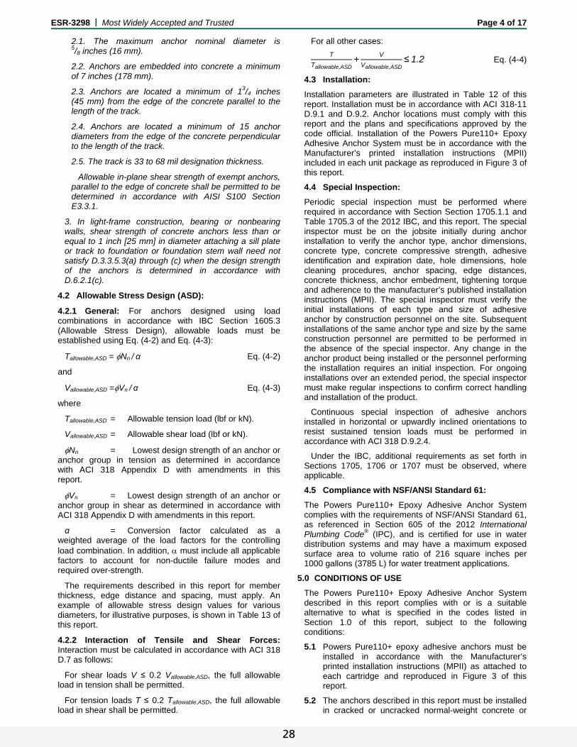
ESR-3298 | Most Widely Accepted and Trusted Page 4 of 17
2.1. The maximum anchor nominal diameter is 5/8 inches (16 mm).
2.2. Anchors are embedded into concrete a minimum of 7 inches (178 mm).
2.3. Anchors are located a minimum of 13/4 inches (45 mm) from the edge of the concrete parallel to the length of the track.
2.4. Anchors are located a minimum of 15 anchor diameters from the edge of the concrete perpendicular to the length of the track.
2.5. The track is 33 to 68 mil designation thickness.
Allowable in-plane shear strength of exempt anchors, parallel to the edge of concrete shall be permitted to be determined in accordance with AISI S100 Section E3.3.1.
3. In light-frame construction, bearing or nonbearing walls, shear strength of concrete anchors less than or equal to 1 inch [25 mm] in diameter attaching a sill plate or track to foundation or foundation stem wall need not satisfy D.3.3.5.3(a) through (c) when the design strength of the anchors is determined in accordance with D.6.2.1(c).
4.2 Allowable Stress Design (ASD):
4.2.1 General: For anchors designed using load combinations in accordance with IBC Section 1605.3 (Allowable Stress Design), allowable loads must be established using Eq. (4-2) and Eq. (4-3):
Tallowable,ASD = Nn / α Eq. (4-2)
and
Vallowable,ASD =Vn / α Eq. (4-3)
where
Tallowable,ASD = Allowable tension load (lbf or kN).
Vallowable,ASD = Allowable shear load (lbf or kN).
Nn = Lowest design strength of an anchor or anchor group in tension as determined in accordance with ACI 318 Appendix D with amendments in this report.
Vn = Lowest design strength of an anchor or anchor group in shear as determined in accordance with ACI 318 Appendix D with amendments in this report.
α = Conversion factor calculated as a weighted average of the load factors for the controlling load combination. In addition, must include all applicable factors to account for non-ductile failure modes and required over-strength.
The requirements described in this report for member thickness, edge distance and spacing, must apply. An example of allowable stress design values for various diameters, for illustrative purposes, is shown in Table 13 of this report.
4.2.2 Interaction of Tensile and Shear Forces: Interaction must be calculated in accordance with ACI 318 D.7 as follows:
For shear loads V ≤ 0.2 Vallowable,ASD, the full allowable load in tension shall be permitted.
For tension loads T ≤ 0.2 Tallowable,ASD, the full allowable load in shear shall be permitted.
For all other cases:
T
Tallowable,ASD+
V
Vallowable,ASD≤1.2 Eq. (4-4)
4.3 Installation:
Installation parameters are illustrated in Table 12 of this report. Installation must be in accordance with ACI 318-11 D.9.1 and D.9.2. Anchor locations must comply with this report and the plans and specifications approved by the code official. Installation of the Powers Pure110+ Epoxy Adhesive Anchor System must be in accordance with the Manufacturer’s printed installation instructions (MPII) included in each unit package as reproduced in Figure 3 of this report.
4.4 Special Inspection:
Periodic special inspection must be performed where required in accordance with Section Section 1705.1.1 and Table 1705.3 of the 2012 IBC, and this report. The special inspector must be on the jobsite initially during anchor installation to verify the anchor type, anchor dimensions, concrete type, concrete compressive strength, adhesive identification and expiration date, hole dimensions, hole cleaning procedures, anchor spacing, edge distances, concrete thickness, anchor embedment, tightening torque and adherence to the manufacturer’s published installation instructions (MPII). The special inspector must verify the initial installations of each type and size of adhesive anchor by construction personnel on the site. Subsequent installations of the same anchor type and size by the same construction personnel are permitted to be performed in the absence of the special inspector. Any change in the anchor product being installed or the personnel performing the installation requires an initial inspection. For ongoing installations over an extended period, the special inspector must make regular inspections to confirm correct handling and installation of the product.
Continuous special inspection of adhesive anchors installed in horizontal or upwardly inclined orientations to resist sustained tension loads must be performed in accordance with ACI 318 D.9.2.4.
Under the IBC, additional requirements as set forth in Sections 1705, 1706 or 1707 must be observed, where applicable.
4.5 Compliance with NSF/ANSI Standard 61:
The Powers Pure110+ Epoxy Adhesive Anchor System complies with the requirements of NSF/ANSI Standard 61, as referenced in Section 605 of the 2012 International Plumbing Code® (IPC), and is certified for use in water distribution systems and may have a maximum exposed surface area to volume ratio of 216 square inches per 1000 gallons (3785 L) for water treatment applications.
5.0 CONDITIONS OF USE
The Powers Pure110+ Epoxy Adhesive Anchor System described in this report complies with or is a suitable alternative to what is specified in the codes listed in Section 1.0 of this report, subject to the following conditions:
5.1 Powers Pure110+ epoxy adhesive anchors must be installed in accordance with the Manufacturer’s printed installation instructions (MPII) as attached to each cartridge and reproduced in Figure 3 of this report.
5.2 The anchors described in this report must be installed in cracked or uncracked normal-weight concrete or
28

ESR-3298 | Most Widely Accepted and Trusted Page 5 of 17
lightweight concrete having a specified compressive strength, f′c = 2,500 psi to 8,500 psi (17.2 MPa to 58.6 MPa).
5.3 The values of f′c used for calculation purposes must not exceed 8,000 psi (55.2 MPa).Anchors must be installed in concrete base materials in holes predrilled in accordance with the instructions provided in Figure 3 of this report.
5.4 Loads applied to the anchors must be adjusted in accordance with Section 1605.2 of the IBC for strength design and in accordance with Section 1605.3 of the IBC for allowable stress design.
5.5 Powers Pure110+ epoxy adhesive anchors are recognized for use to resist short and long-term loads, including wind and earthquake, subject to the conditions of this report.
5.6 In structures assigned to Seismic Design Categories C, D, E, and F under the IBC or IRC, anchor strength must be adjusted in accordance with Section 4.1.11 of this report.
5.7 Powers Pure110+ epoxy adhesive anchors are permitted to be installed in concrete that is cracked or that may be expected to crack during the service life of the anchor, subject to the conditions of this report.
5.8 Strength design values must be established in accordance with Section 4.1 of this report.
5.9 Allowable stress design values must be established in accordance with Section 4.2 of this report.
5.10 Minimum anchor spacing and edge distance, as well as minimum member thickness, must comply with the values described in this report.
5.11 Prior to anchor installation, calculations and details demonstrating compliance with this report must be submitted to the code official. The calculations and details must be prepared by a registered design professional where required by the statutes of the jurisdiction in which the project is to be constructed.
5.12 Anchors are not permitted to support fire-resistive construction. Where not otherwise prohibited by the code, Powers Pure110+ epoxy adhesive anchors are permitted for installation in fire-resistive construction provided that at least one of the following conditions is fulfilled:
Anchors are used to resist wind or seismic forces only.
Anchors that support gravity load-bearing structural elements are within a fire-resistive envelope or a fire-resistive membrane, are protected by approved fire-resistive materials, or have been evaluated for resistance to fire exposure in accordance with recognized standards.
Anchors are used to support non-structural elements.
5.13 Since an ICC-ES acceptance criteria for evaluating data to determine the performance of adhesive anchors subjected to fatigue or shock loading is unavailable at this time, the use of these anchors under such conditions is beyond the scope of this report.
5.14 Use of zinc-plated carbon steel threaded rods or steel reinforcing bars is limited to dry, interior locations.
5.15 Use of hot-dipped galvanized carbon steel and stainless steel rods is permitted for exterior exposure or damp environments.
5.16 Steel anchoring materials in contact with preservative-treated wood and fire-retardant-treated wood must be of zinc-coated carbon steel or stainless steel. The minimum coating weights for zinc-coated steel must comply with ASTM A153.
5.17 Periodic special inspection must be provided in accordance with Section 4.4 of this report. Continuous special inspection of anchors installed in horizontal or upwardly inclined orientations to resist sustained tension loads must be provided in accordance with Section 4.4 of this report.
5.18 Installation of anchors in horizontal or upwardly inclined orientations to resist sustained tension loads must be performed by personnel certified by an applicable certification program in accordance with ACI 318 D.9.2.2 or D.9.2.3.
5.19 Powers Pure110+ epoxy adhesive is manufactured under an approved quality control program with inspections by ICC-ES.
6.0 EVIDENCE SUBMITTED
Data in accordance with the ICC-ES Acceptance Criteria for Post-installed Adhesive Anchors in Concrete (AC308), dated September 2014, which incorporates requirements in ACI 355.4-11 for use in cracked and uncracked concrete; including, but not limited to, tests under freeze/thaw conditions, tests under sustained load, tests for installation including installation direction, tests at elevated temperatures, tests for resistance to alkalinity, tests for resistance to sulfur and tests for seismic tension and shear.
7.0 IDENTIFICATION
Powers Pure110+ epoxy adhesive is identified by packaging labeled with the lot number, expiration date, company name and corresponding product name as set forth in Table A of this report, and the evaluation report number (ESR-3298). Threaded rods, nuts, washers and deformed reinforcing bars are standard steel anchor elements and must conform to applicable national or international specifications as set forth in Tables 2 and 3 of this report.
29

ESR-3298 | Most Widely Accepted and Trusted Page 6 of 17
TABLE A—PRODUCT NAMES BY COMPANY
COMPANY NAME PRODUCT NAME
Powers Fasteners Pure110+
DEWALT (Stanley Black & Decker) Pure110-PRO
TABLE 1—DESIGN USE AND REPORT TABLE INDEX
DESIGN STRENGTH1 THREADED ROD (FRACTIONAL)
DEFORMED REINFORCING BAR
(FRACTIONAL)
THREADED ROD (METRIC)
DEFORMED REINFORCING BAR
(METRIC)
Steel Nsa, Vsa Table 4 Table 5 Table 8 Table 9
Concrete Ncb, Ncbg, Vcb, Vcbg, Vcp, Vcpg Table 6 Table 6 Table 10 Table 10
Bond2 Na, Nag Table 7 Table 7 Table 11 Table 11
For SI: 1 inch = 25.4 mm. For pound-inch units: 1 mm = 0.03937 inch. 1Reference ACI 318-11 D.4.1.1. The controlling strength is decisive from all appropriate failure modes (i.e. steel, concrete, bond) and design assumptions. 2See Section 4.1.4 of this report for bond strength determination. 3See Section 4.1.11 for requirements for seismic design, where applicable.
FIGURE 1—FLOWCHART FOR THE ESTABLISHMENT OF DESIGN BOND STRENGTH
CONCRETE TYPE
CONCRETE STATE
THREADED ROD DIAMETER (inch)
REINFORCINGBAR SIZE (No.)
DRILLINGMETHOD
MINIMUMEMBEDMENT
MAXIMUM EMBEDMENT
SEISMIC DESIGNCATEGORIES3
Normal-weight and lightweight
Cracked 3/8, 1/2,
5/8, 3/4,
7/8, 1 and 11/4 3, 4, 5, 6, 7, 8, 9, 10 Hammer-drill See Table 7 See Table 7 A through F
Uncracked 3/8, 1/2,
5/8, 3/4,
7/8, 1 and 11/4 3, 4, 5, 6, 7, 8, 9, 10 Hammer-drill See Table 7 See Table 7 A through F
CONCRETE TYPE
CONCRETE STATE
THREADED ROD DIAMETER (mm)
REINFORCINGBAR SIZE (Ø)
DRILLINGMETHOD
MINIMUMEMBEDMENT
MAXIMUM EMBEDMENT
SEISMIC DESIGNCATEGORIES3
Normal-weight and lightweight
Cracked 10, 12, 16, 20, 24, 27 and 30 10, 12, 14, 16, 20,
25, 28, 32 Hammer-drill See Table 11 See Table 11 A through F
Uncracked 10, 12, 16, 20, 24, 27 and 30 10, 12, 14, 16, 20, 25, 28, 32
Hammer-drill See Table 11 See Table 11 A through F
30

ESR-3298 | Most Widely Accepted and Trusted Page 7 of 17
TABLE 2—SPECIFICATIONS AND PHYSICAL PROPERTIES OF COMMON THREADED CARBON AND STAINLESS STEEL ROD MATERIALS1
THREADED ROD SPECIFICATION UNITS MIN. SPECIFIED
ULTIMATE STRENGTH, futa
MIN. SPECIFIED YIELD STRENGTH
0.2 PERCENT OFFSET, fya
futa fya
ELONGATIONMINIMUM
PERCENT11
REDUCTION OF AREA
MIN. PERCENT
NUT SPECIFICATION12
Carbon Steel
ASTM A362 and F15543 Grade 36
psi (MPa)
58,000 (400)
36,000 (248)
1.61 23 40 (50 for A36) ASTM A194 / A563 Grade A ASTM F15543
Grade 55 psi
(MPa) 75,000 (517)
55,000 (380)
1.36 23 40
ASTM F15543 Grade 105
psi (MPa)
125,000 (862)
105,000 (724)
1.19 15 45 ASTM A194 /
A563 Grade DH ASTM A1934 Grade B7
psi (MPa)
125,000 (860)
105,000 (720)
1.19 16 50
ASTM A4495 (3/8 to 1 inch dia.)
psi (MPa)
120,000 (828)
92,000 (635)
1.30 14 35 ASTM A194 /
A563 Grade DH ASTM A4495 (11/4 inch dia.)
psi (MPa)
105,000 (720)
81,000 (560)
1.30 14 35
ASTM F568M6 Class 5.8 (equivalent to ISO 898-1)
psi (MPa)
72,500 (500)
58,000 (400)
1.25 10 35 ASTM A563 Grade DH
DIN 934 (8-A2K)13
ISO 898-17 Class 5.8 MPa (psi)
500 (72,500)
400 (58,000)
1.25 22 -14 DIN 934 Grade 6
ISO 898-17 Class 8.8 MPa (psi)
800 (116,000)
640 (92,800)
1.25 12 52 DIN 934 Grade 8
Stainless Steel
ASTM F5938 CW1 (3/8 to 5/8 inch dia.)
psi (MPa)
100,000 (690)
65,000 (450)
1.54 20 -14 ASTM F594 Alloy Group
1, 2 or 3 ASTM F5938 CW2 (3/4 to 11/4 inch dia.)
psi (MPa)
85,000 (590)
45,000 (310)
1.89 25 -14
ASTM A193/A193M9 Grade B8/B8M, Class 1
psi (MPa)
75,000 (515)
30,000 (205)
2.50 30 50 ASTM A194/A194M
ASTM A193/A193M9 Grade B8/B8M2, Class 2B
psi (MPa)
95,000 (655)
75,000 (515)
1.27 25 40
ISO 3506-110 A4-70 and HCR-70 (M8 – M24)
MPa (psi)
700 (101,500)
450 (65,250)
1.56 40 -14 ISO 4032
ISO 3506-110 A4-50 and HCR-50 (M27 – M30)
MPa (psi)
500 (72,500)
210 (30,450)
2.38 40 -14
For SI: 1 inch = 25.4 mm, 1 psi = 0.006897 MPa. For pound-inch units: 1 mm = 0.03937 inch, 1 MPa = 145.0 psi.
1Pure110+ epoxy adhesive may be used in conjunction with all grades of continuously threaded carbon or stainless steels (all-thread) that comply with this table and that have thread characteristics comparable with ANSI B1.1 UNC Coarse Thread Series or ANSI B1.13M M Profile Metric Thread Series. Tabulated values correspond to anchor diameters included in this report. See Section 3.2.4.3 of this report for ductility of steel anchor elements.
2Standard Specification for Carbon Structural Steel. 3Standard Specification for Anchor Bolts, Steel, 36, 55, and 105-ksi Yield Strength. 4Standard Specification for Alloy-Steel and Stainless Steel Bolting Materials for High Temperature or High Pressure Service and Other Special Purpose
Applications. 5Standard Specification for Hex Cap Screws, Bolts and Studs, Steel, Heat Treated, 120/105/90 ksi Minimum Tensile Strength, General Use. 6Standard Specification for Carbon and Alloy Steel Externally Threaded Metric Fasteners. 7Mechanical properties of fasteners made of carbon steel and alloy steel – Part 1: Bolts, screws and studs
8Standard Specification for Stainless Steel Bolts, Hex Cap Screws, and Studs. 9Standard Standard Specification for Alloy-Steel and Stainless Steel Bolting for High Temperature or High Pressure Service and Other Special Purpose
Applications. 10 Mechanical properties of fasteners made of corrosion-resistant stainless steel fasteners – Part 1: Bolts, screws and studs
11Based on 2-inch (50 mm) gauge length except ASTM A193, which are based on a gauge length of 4d and ISO 898, which is based on 5d. 12Nuts of other grades and style having specified proof load stress greater than the specified grade and style are also suitable. Nuts must have specified proof load
stresses equal to or greater than the minimum tensile strength of the specified threaded rod. Material types of the nuts and washers must be matched to the threaded rods.
13Nuts for metric rods. 14Minimum percent reduction of area not reported in the referenced standard.
TABLE 3—SPECIFICATIONS AND PHYSICAL PROPERTIES OF COMMON STEEL REINFORCING BARS1
REINFORCING SPECIFICATION UNITS MINIMUM SPECIFIED ULTIMATE STRENGTH, futa MINIMUM SPECIFIED YIELD STRENGTH, fya
ASTM A6152, A7674, Grade 75 psi
(MPa) 100,000
(690) 75,000 (520)
ASTM A6152, A7674, Grade 60 psi
(MPa) 90,000 (620)
60,000 (420)
ASTM A7063, A7674, Grade 60 psi
(MPa) 80,000 (550)
60,000 (420)
ASTM A6152, A7674, Grade 40 psi
(MPa) 60,000 (420)
40,000 (280)
DIN 4885 BSt 500 MPa (psi)
550 (80,000)
500 (72,500)
For SI: 1 psi = 0.006897 MPa. For pound-inch units: 1 MPa = 145.0 psi.
1Adhesive must be used with specified deformed reinforcing bars. Tabulated values correspond to bar sizes included in this report. 2Standard Specification for Deformed and Plain Carbon-Steel Bars for Concrete Reinforcement. Grade 40 and Grade 60 bars furnished to specification are
considered ductile elements. In accordance with ACI 318-11 D.3.3.4.3(a)6, deformed reinforcing bars meeting this specification used as ductile steel elements to resist earthquake effects shall be limited to reinforcing bars bars satisfying the requirements of 21.1.5.2(a) and (b). Grade 75 bars furnished to specification are considered brittle elements unless evidence is otherwise shown to the satisfaction of the registered design professional and code official in accordance with Section 3.2.4.3 of this report.
3Standard Specification for Low-Alloy Steel Deformed and Plain Bars for Concrete Reinforcement. Bars furnished to specification are considered ductile elements. 4Standard Specification for Zinc-Coated (Galvanized) Steel Bars for Concrete Reinforcement. Bars furnished to specification are considered brittle elements unless
evidence is otherwise shown to the satisfaction of the registered design professional and code official in accordance with Section 3.2.4.3 of this report. 5Reinforcing steel; reinforcing steel bars; dimensions and masses. Bars furnished to this specification are considered brittle elements unless evidence is otherwise
shown to the satisfaction of the registered design professional and code official in accordance with Section 3.2.4.3 of this report.
31
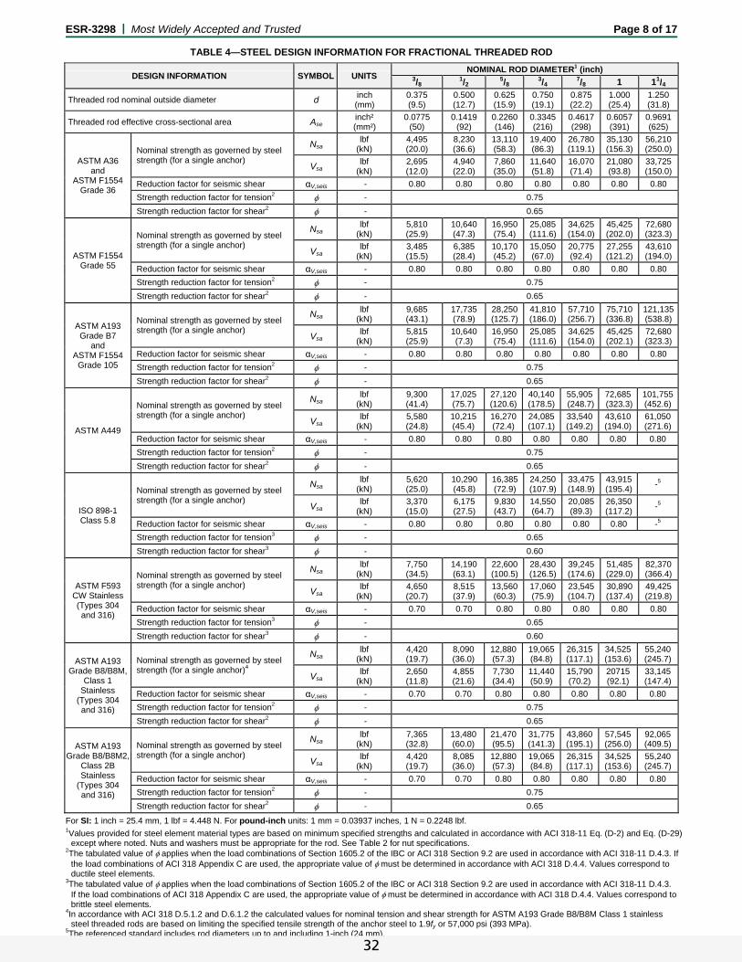
ESR-3298 | Most Widely Accepted and Trusted Page 8 of 17
TABLE 4—STEEL DESIGN INFORMATION FOR FRACTIONAL THREADED ROD
For SI: 1 inch = 25.4 mm, 1 lbf = 4.448 N. For pound-inch units: 1 mm = 0.03937 inches, 1 N = 0.2248 lbf.
1Values provided for steel element material types are based on minimum specified strengths and calculated in accordance with ACI 318-11 Eq. (D-2) and Eq. (D-29) except where noted. Nuts and washers must be appropriate for the rod. See Table 2 for nut specifications.
2The tabulated value of applies when the load combinations of Section 1605.2 of the IBC or ACI 318 Section 9.2 are used in accordance with ACI 318-11 D.4.3. If the load combinations of ACI 318 Appendix C are used, the appropriate value of must be determined in accordance with ACI 318 D.4.4. Values correspond to ductile steel elements.
3The tabulated value of applies when the load combinations of Section 1605.2 of the IBC or ACI 318 Section 9.2 are used in accordance with ACI 318-11 D.4.3. If the load combinations of ACI 318 Appendix C are used, the appropriate value of must be determined in accordance with ACI 318 D.4.4. Values correspond to brittle steel elements.
4In accordance with ACI 318 D.5.1.2 and D.6.1.2 the calculated values for nominal tension and shear strength for ASTM A193 Grade B8/B8M Class 1 stainless steel threaded rods are based on limiting the specified tensile strength of the anchor steel to 1.9fy or 57,000 psi (393 MPa).
5The referenced standard includes rod diameters up to and including 1-inch (24 mm).
DESIGN INFORMATION SYMBOL UNITS NOMINAL ROD DIAMETER1 (inch)
3/81/2
5/83/4
7/8 1 11/4
Threaded rod nominal outside diameter d inch (mm)
0.375 (9.5)
0.500 (12.7)
0.625 (15.9)
0.750 (19.1)
0.875 (22.2)
1.000 (25.4)
1.250 (31.8)
Threaded rod effective cross-sectional area Ase inch² (mm²)
0.0775 (50)
0.1419 (92)
0.2260 (146)
0.3345 (216)
0.4617 (298)
0.6057 (391)
0.9691 (625)
ASTM A36 and
ASTM F1554 Grade 36
Nominal strength as governed by steel strength (for a single anchor)
Nsa lbf
(kN) 4,495 (20.0)
8,230 (36.6)
13,110 (58.3)
19,400 (86.3)
26,780 (119.1)
35,130 (156.3)
56,210 (250.0)
Vsa lbf
(kN) 2,695 (12.0)
4,940 (22.0)
7,860 (35.0)
11,640 (51.8)
16,070 (71.4)
21,080 (93.8)
33,725 (150.0)
Reduction factor for seismic shear αV,seis - 0.80 0.80 0.80 0.80 0.80 0.80 0.80
Strength reduction factor for tension2 - 0.75
Strength reduction factor for shear2 - 0.65
ASTM F1554 Grade 55
Nominal strength as governed by steel strength (for a single anchor)
Nsa lbf
(kN) 5,810 (25.9)
10,640 (47.3)
16,950 (75.4)
25,085 (111.6)
34,625 (154.0)
45,425 (202.0)
72,680 (323.3)
Vsa lbf
(kN) 3,485 (15.5)
6,385 (28.4)
10,170 (45.2)
15,050 (67.0)
20,775 (92.4)
27,255 (121.2)
43,610 (194.0)
Reduction factor for seismic shear αV,seis - 0.80 0.80 0.80 0.80 0.80 0.80 0.80
Strength reduction factor for tension2 - 0.75
Strength reduction factor for shear2 - 0.65
ASTM A193 Grade B7
and ASTM F1554
Grade 105
Nominal strength as governed by steel strength (for a single anchor)
Nsalbf
(kN) 9,685 (43.1)
17,735 (78.9)
28,250 (125.7)
41,810 (186.0)
57,710 (256.7)
75,710 (336.8)
121,135(538.8)
Vsalbf
(kN) 5,815 (25.9)
10,640 (7.3)
16,950 (75.4)
25,085 (111.6)
34,625 (154.0)
45,425 (202.1)
72,680 (323.3)
Reduction factor for seismic shear αV,seis - 0.80 0.80 0.80 0.80 0.80 0.80 0.80
Strength reduction factor for tension2 - 0.75
Strength reduction factor for shear2 - 0.65
ASTM A449
Nominal strength as governed by steel strength (for a single anchor)
Nsalbf
(kN) 9,300 (41.4)
17,025 (75.7)
27,120 (120.6)
40,140 (178.5)
55,905 (248.7)
72,685 (323.3)
101,755 (452.6)
Vsalbf
(kN) 5,580 (24.8)
10,215 (45.4)
16,270 (72.4)
24,085 (107.1)
33,540 (149.2)
43,610 (194.0)
61,050 (271.6)
Reduction factor for seismic shear αV,seis - 0.80 0.80 0.80 0.80 0.80 0.80 0.80
Strength reduction factor for tension2 - 0.75
Strength reduction factor for shear2 - 0.65
ISO 898-1
Class 5.8
Nominal strength as governed by steel strength (for a single anchor)
Nsalbf
(kN) 5,620 (25.0)
10,290 (45.8)
16,385 (72.9)
24,250 (107.9)
33,475 (148.9)
43,915 (195.4)
-5
Vsalbf
(kN) 3,370 (15.0)
6,175 (27.5)
9,830 (43.7)
14,550 (64.7)
20,085 (89.3)
26,350 (117.2)
-5
Reduction factor for seismic shear αV,seis - 0.80 0.80 0.80 0.80 0.80 0.80 -5
Strength reduction factor for tension3 - 0.65
Strength reduction factor for shear3 - 0.60
ASTM F593 CW Stainless (Types 304 and 316)
Nominal strength as governed by steel strength (for a single anchor)
Nsa lbf
(kN) 7,750 (34.5)
14,190 (63.1)
22,600 (100.5)
28,430 (126.5)
39,245 (174.6)
51,485 (229.0)
82,370 (366.4)
Vsa lbf
(kN) 4,650 (20.7)
8,515 (37.9)
13,560 (60.3)
17,060 (75.9)
23,545 (104.7)
30,890 (137.4)
49,425 (219.8)
Reduction factor for seismic shear αV,seis - 0.70 0.70 0.80 0.80 0.80 0.80 0.80
Strength reduction factor for tension3 - 0.65
Strength reduction factor for shear3 - 0.60
ASTM A193 Grade B8/B8M,
Class 1 Stainless
(Types 304 and 316)
Nominal strength as governed by steel strength (for a single anchor)4
Nsalbf
(kN) 4,420 (19.7)
8,090 (36.0)
12,880 (57.3)
19,065 (84.8)
26,315 (117.1)
34,525 (153.6)
55,240 (245.7)
Vsalbf
(kN) 2,650 (11.8)
4,855 (21.6)
7,730 (34.4)
11,440 (50.9)
15,790 (70.2)
20715 (92.1)
33,145 (147.4)
Reduction factor for seismic shear αV,seis - 0.70 0.70 0.80 0.80 0.80 0.80 0.80
Strength reduction factor for tension2 - 0.75
Strength reduction factor for shear2 - 0.65
ASTM A193 Grade B8/B8M2,
Class 2B Stainless
(Types 304 and 316)
Nominal strength as governed by steel strength (for a single anchor)
Nsalbf
(kN) 7,365 (32.8)
13,480 (60.0)
21,470 (95.5)
31,775 (141.3)
43,860 (195.1)
57,545 (256.0)
92,065 (409.5)
Vsalbf
(kN) 4,420 (19.7)
8,085 (36.0)
12,880 (57.3)
19,065 (84.8)
26,315 (117.1)
34,525 (153.6)
55,240 (245.7)
Reduction factor for seismic shear αV,seis - 0.70 0.70 0.80 0.80 0.80 0.80 0.80
Strength reduction factor for tension2 - 0.75
Strength reduction factor for shear2 - 0.65
32

ESR-3298 | Most Widely Accepted and Trusted Page 9 of 17
TABLE 5—STEEL DESIGN INFORMATION FOR FRACTIONAL REINFORCING BARS
DESIGN INFORMATION SYMBOL UNITS NOMINAL REINFORCING BAR SIZE (REBAR)1
No. 3 No. 4 No. 5 No. 6 No. 7 No. 8 No. 9 No. 10
Rebar nominal outside diameter d inch (mm)
0.375 (9.5)
0.500 (12.7)
0.625 (15.9)
0.750 (19.1)
0.875 (22.2)
1.000 (25.4)
1.125 (28.7)
1.250 (32.3)
Rebar effective cross-sectional area Ase inch2 (mm2)
0.110 (71.0)
0.200 (129.0)
0.310 (200.0)
0.440 (283.9)
0.600 (387.1)
0.790 (509.7)
1.000 (645.2)
1.270 (819.4)
ASTM A615 Grade
75
Nominal strength as governed by steel strength (for a single anchor)
Nsa lbf
(kN) 11,000 (48.9)
20,000 (89.0)
31,000 (137.9)
44,000 (195.7)
60,000 (266.9)
79,000 (351.4)
100,000(444.8)
127,000(564.9)
Vsa lbf
(kN) 6,600 (29.4)
12,000 (53.4)
18,600 (82.7)
26,400 (117.4)
36,000 (160.1)
47,400 (210.8)
60,000 (266.9)
76,200 (338.9)
Reduction factor for seismic shear αV,seis - 0.70 0.70 0.80 0.80 0.80 0.80 0.80 0.80
Strength reduction factor for tension3 - 0.65
Strength reduction factor for shear3 - 0.60
ASTM A615 Grade
60
Nominal strength as governed by steel strength (for a single anchor)
Nsa lbf
(kN) 9,900 (44.0)
18,000 (80.1)
27,900 (124.1)
39,600 (176.1)
54,000 (240.2)
71,100 (316.3)
90,000 (400.3)
114,300(508.4)
Vsa lbf
(kN) 5,940 (26.4)
10,800 (48.0)
16,740 (74.5)
23,760 (105.7)
32,400 (144.1)
42,660 (189.8)
54,000 (240.2)
68,580 (305.0)
Reduction factor for seismic shear αV,seis - 0.70 0.70 0.80 0.80 0.80 0.80 0.80 0.80
Strength reduction factor for tension2 - 0.75
Strength reduction factor for shear2 - 0.65
ASTM A706 Grade
60
Nominal strength as governed by steel strength (for a single anchor)
Nsa lbf
(kN) 8,800 (39.1)
16,000 (71.2)
24,800 (110.3)
35,200 (156.6)
48,000 (213.5)
63,200 (281.1)
80,000 (355.9)
101,600(452.0)
Vsa lbf
(kN) 5,280 (23.5)
9,600 (42.7)
14,880 (66.2)
21,120 (94.0)
28,800 (128.1)
37,920 (168.7)
48,000 (213.5)
60,960 (271.2)
Reduction factor for seismic shear αV,seis - 0.70 0.70 0.80 0.80 0.80 0.80 0.80 0.80
Strength reduction factor for tension2 - 0.75
Strength reduction factor for shear2 - 0.65
ASTM A615 Grade
40
Nominal strength as governed by steel strength (for a single anchor)
Nsa lbf
(kN) 6,600 (29.4)
12,000 (53.4)
18,600 (82.7)
26,400 (117.4) In accordance with ASTM A615,
Grade 40 bars are furnished only in sizes No. 3 through No. 6
Vsa lbf
(kN) 3,960 (17.6)
7,200 (32.0)
11,160 (49.6)
15,840 (70.5)
Reduction factor for seismic shear αV,seis - 0.70 0.70 0.80 0.80
Strength reduction factor for tension2 - 0.75
Strength reduction factor for shear2 - 0.65
For SI: 1 inch = 25.4 mm, 1 lbf = 4.448 N. For pound-inch units: 1 mm = 0.03937 inches, 1 N = 0.2248 lbf. 1Values provided for reinforcing bar material types based on minimum specified strengths and calculated in accordance with ACI 318-11 Eq. (D-2) and Eq. (D-29). 2The tabulated value of applies when the load combinations of Section 1605.2 of the IBC or ACI 318 Section 9.2 are used in accordance with ACI 318 D.4.3. If the load combinations of ACI 318 Appendix C are used, the appropriate value of must be determined in accordance with ACI 318 D.4.4. Values correspond to ductile steel elements. In accordance with ACI 318-11 D.3.3.4.3(a)6, deformed reinforcing bars meeting this specification used as ductile steel elements to resist earthquake effects shall be limited to reinforcing bars bars satisfying the requirements of 21.1.5.2(a) and (b). 3The tabulated value of applies when the load combinations of Section 1605.2 of the IBC or ACI 318 Section 9.2 are used in accordance with ACI 318 D.4.3. If the load combinations of ACI 318 Appendix C are used, the appropriate value of must be determined in accordance with ACI 318 D.4.4. Values correspond to brittle steel elements.
TABLE 6—CONCRETE BREAKOUT DESIGN INFORMATION FOR FRACTIONAL THREADED ROD AND REINFORCING BARS1
DESIGN INFORMATION SYMBOL UNITS NOMINAL ROD DIAMETER (inch) / REINFORCING BAR SIZE
3/8 or #3 1/2 or #4 5/8 or #5 3/4 or #6 7/8 or #7 1 or #8 #9 11/4 or #10
Effectiveness factor for cracked concrete kc,cr -
(SI) 17
(7.1)
Effectiveness factor for uncracked concrete kc,uncr -
(SI) 24
(10.0)
Minimum embedment hef,min inch (mm)
23/8 (60)
23/4 (70)
31/8 (79)
31/2 (89)
31/2 (89)
4 (102)
41/2 (114)
5 (127)
Maximum embedment hef,max inch (mm)
71/2 (191)
10 (254)
121/2 (318)
15 (381)
171/2 (445)
20 (508)
221/2 (572)
25 (635)
Minimum anchor spacing smin inch (mm)
17/8 (48)
21/2 (64)
31/8 (79)
33/4 (95)
43/8 (111)
5 (127)
55/8 (143)
61/4 (159)
Minimum edge distance cmin inch (mm)
5d where d is nominal outside diameter of the anchor; or see Section 4.1.9 of this report for design with reduced minimum edge distances:
13/4 (45)
13/4 (45)
13/4 (45)
13/4 (45)
13/4 (45)
13/4 (45)
23/4 (70)
23/4 (70)
Minimum member thickness hmin inch (mm)
hef + 11/4 (hef + 30)
hef + 2do where do is hole diameter; for installation parameters see Table 12 of this report
Critical edge distance—splitting (for uncracked concrete only) cac
inch (mm)
See Section 4.1.10 of this report
Strength reduction factor for tension, concrete failure modes, Condition B2 - 0.65
Strength reduction factor for shear, concrete failure modes, Condition B2 - 0.70
For SI: 1 inch = 25.4 mm, 1 lbf = 4.448 N. For pound-inch units: 1 mm = 0.03937 inch, 1 N = 0.2248 lbf. 1Additional setting information is described in the installation instructions, Figure 3 of this report. 2Condition A requires supplemental reinforcement, while Condition B applies where supplemental reinforcement is not provided or where pryout governs, as set forth in ACI 318 D.4.3. The tabulated value of applies when the load combinations of Section 1605.2 of the IBC or ACI 318 Section 9.2 are used in accordance with ACI 318 D.4.3. If the load combinations of ACI 318 Appendix C are used, the appropriate value of must be determined in accordance with ACI 318 D.4.4.
33

ESR-3298 | Most Widely Accepted and Trusted Page 10 of 17
TABLE 7—BOND STRENGTH DESIGN INFORMATION FOR FRACTIONAL THREADED RODS AND REINFORCING BARS1
DESIGN INFORMATION SYMBOL UNITS NOMINAL ROD DIAMETER (inch) / REINFORCING BAR SIZE
3/8 or #3 1/2 or #4 5/8 or #5 3/4 or #6 7/8 or #7 1 or #8 #9 11/4 or #10
Minimum embedment hef,min inch (mm)
23/8 (60)
23/4 (70)
31/8 (79)
31/2 (89)
31/2 (89)
4 (102)
41/2 (114)
5 (127)
Maximum embedment hef,max inch (mm)
71/2 (191)
10 (254)
121/2 (318)
15 (381)
171/2 (445)
20 (508)
221/2 (572)
25 (635)
110°F (43°C) Maximum long-
term service temperature;
140°F (60°C) maximum short-
term service temperature3,5
Characteristic bond strength in cracked concrete6,9
k,cr
psi (N/mm2)
990 (6.8)
990 (6.8)
959 (6.6)
959 (6.6)
959 (6.6)
918 (6.3)
846 (5.8)
846 (5.8)
Characteristic bond strength in cracked concrete, short-term loading only9
psi (N/mm2)
990 (6.8)
990 (6.8)
959 (6.6)
959 (6.6)
959 (6.6)
918 (6.3)
846 (5.8)
846 (5.8)
Characteristic bond strength in uncracked concrete6,8
k,uncr
psi (N/mm2)
1,756 (12.1)
1,668 (11.5)
1,604 (11.1)
1,553 (10.7)
1,512 (10.4)
1,477 (10.2)
1,446 (10.0)
1,420 (9.8)
Characteristic bond strength in uncracked concrete, short-term loading only8
psi (N/mm2)
1,756 (12.1)
1,668 (11.5)
1,604 (11.1)
1,553 (10.7)
1,512 (10.4)
1,477 (10.2)
1,446 (10.0)
1,420 (9.8)
110°F (43°C) Maximum long-
term service temperature;
176°F (80°C) maximum short-
term service temperature4,5
Characteristic bond strength in cracked concrete6,9 k,cr
psi (N/mm2)
725 (5.0)
725 (5.0)
696 (4.8)
696 (4.8)
696 (4.8)
667 (4.6)
624 (4.3)
624 (4.3)
Characteristic bond strength in cracked concrete, short-term loading only9
psi (N/mm2)
725 (5.0)
725 (5.0)
696 (4.8)
696 (4.8)
696 (4.8)
667 (4.6)
624 (4.3)
624 (4.3)
Characteristic bond strength in uncracked concrete6,8
k,uncr
psi (N/mm2)
1,276 (8.8)
1,218 (8.4)
1,175 (8.1)
1,131 (7.6)
1,102 (7.6)
1,073 (7.4)
1,059 (7.3)
1,030 (7.1)
Characteristic bond strength in uncracked concrete, short-term loading only8
psi (N/mm2)
1,276 (8.8)
1,218 (8.4)
1,175 (8.1)
1,131 (7.6)
1,102 (7.6)
1,073 (7.4)
1,059 (7.3)
1,030 (7.1)
Permissible installation conditions7
Dry concrete Anchor
Category - 1
d - 0.65
Water-saturated concrete, Water-filled hole (flooded)
Anchor Category - 2
ws, wf, - 0.55
Underwater (submerged) Anchor
Category - 2 3
uw - 0.55 0.45
Reduction factor for seismic tension9 αN,seis - 1.0
For SI: 1 inch = 25.4 mm, 1 psi = 0.006894 MPa. For pound-inch units: 1 mm = 0.03937 inch, 1 MPa = 145.0 psi.
1Bond strength values correspond to a normal-weight concrete compressive strength f'c = 2,500 psi (17.2 MPa). For concrete compressive strength, f'c between 2,500 psi and 8,000 psi (17.2 MPa and 55.2 MPa), the tabulated characteristic bond strength may be increased by a factor of (f'c / 2,500)0.23 [For SI: (f'c / 17.2)0.23]. See Section 4.1.4 of this report for bond strength determination.
2The modification factor for bond strength of adhesive anchors in lightweight concrete shall be taken as given in ACI 318 D.3.6, where applicable. 3The maximum short-term service temperature may be increased to 162°F (72°C) provided characteristic bond strengths are reduced by 3 percent. Long-term and short-term temperatures meet the requirements of Section 8.5 of ACI 355.4 and Table 8.1, Temperature Category B. 4Long-term and short-term temperatures meet the requirements of Section 8.5 of ACI 355.4 and Table 8.1, Temperature Category A. 5Short-term base material service temperatures are those that occur over brief intervals, e.g. as a result of diurnal cycling. Long-term base material service
temperatures are roughly constant over significant periods of time. 6Characteristic bond strengths are for sustained loads including dead and live loads. 7Permissible installation conditions include dry concrete, water-saturated concrete, water-filled holes and underwater. Water-filled holes include applications in dry or water-saturated concrete where the drilled holes contain standing water at the time of anchor installation. For installation instructions see Figure 3 of this report. 8Bond strength values for uncracked concrete are applicable for structures assigned to Seismic Design Categories A and B only. 9For structures assigned to Seismic Design Categories C, D, E or F, the tabulated bond strength values for cracked concrete do not require an additional reduction
factor applied for seismic tension (αN,seis = 1.0), where seismic design is applicable. See Section 4.1.11 of this report for requirements for seismic design.
34
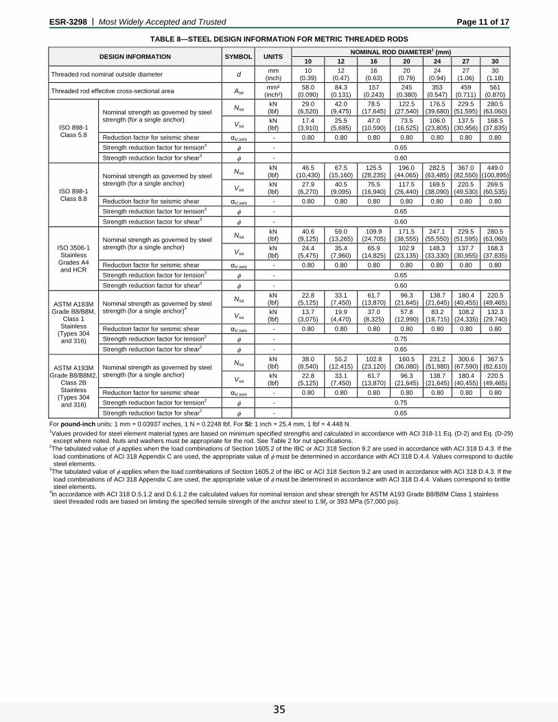
ESR-3298 | Most Widely Accepted and Trusted Page 11 of 17
TABLE 8—STEEL DESIGN INFORMATION FOR METRIC THREADED RODS
For pound-inch units: 1 mm = 0.03937 inches, 1 N = 0.2248 lbf. For SI: 1 inch = 25.4 mm, 1 lbf = 4.448 N.
1Values provided for steel element material types are based on minimum specified strengths and calculated in accordance with ACI 318-11 Eq. (D-2) and Eq. (D-29) except where noted. Nuts and washers must be appropriate for the rod. See Table 2 for nut specifications.
2The tabulated value of applies when the load combinations of Section 1605.2 of the IBC or ACI 318 Section 9.2 are used in accordance with ACI 318 D.4.3. If the load combinations of ACI 318 Appendix C are used, the appropriate value of must be determined in accordance with ACI 318 D.4.4. Values correspond to ductile steel elements.
3The tabulated value of applies when the load combinations of Section 1605.2 of the IBC or ACI 318 Section 9.2 are used in accordance with ACI 318 D.4.3. If the load combinations of ACI 318 Appendix C are used, the appropriate value of must be determined in accordance with ACI 318 D.4.4. Values correspond to brittle steel elements.
4In accordance with ACI 318 D.5.1.2 and D.6.1.2 the calculated values for nominal tension and shear strength for ASTM A193 Grade B8/B8M Class 1 stainless steel threaded rods are based on limiting the specified tensile strength of the anchor steel to 1.9fy or 393 MPa (57,000 psi).
DESIGN INFORMATION SYMBOL UNITS NOMINAL ROD DIAMETER1 (mm)
10 12 16 20 24 27 30
Threaded rod nominal outside diameter d mm
(inch) 10
(0.39) 12
(0.47) 16
(0.63) 20
(0.79) 24
(0.94) 27
(1.06) 30
(1.18)
Threaded rod effective cross-sectional area Ase mm²
(inch²) 58.0
(0.090) 84.3
(0.131) 157
(0.243) 245
(0.380) 353
(0.547) 459
(0.711) 561
(0.870)
ISO 898-1
Class 5.8
Nominal strength as governed by steel strength (for a single anchor)
Nsa kN (lbf)
29.0 (6,520)
42.0 (9,475)
78.5 (17,645)
122.5 (27,540)
176.5 (39,680)
229.5 (51,595)
280.5 (63,060)
Vsa kN (lbf)
17.4 (3,910)
25.5 (5,685)
47.0 (10,590)
73.5 (16,525)
106.0 (23,805)
137.5 (30,956)
168.5 (37,835)
Reduction factor for seismic shear αV,seis - 0.80 0.80 0.80 0.80 0.80 0.80 0.80
Strength reduction factor for tension3 - 0.65
Strength reduction factor for shear3 - 0.60
ISO 898-1
Class 8.8
Nominal strength as governed by steel strength (for a single anchor)
Nsa kN (lbf)
46.5 (10,430)
67.5 (15,160)
125.5 (28,235)
196.0 (44,065)
282.5 (63,485)
367.0 (82,550)
449.0 (100,895)
Vsa kN (lbf)
27.9 (6,270)
40.5 (9,095)
75.5 (16,940)
117.5 (26,440)
169.5 (38,090)
220.5 (49,530)
269.5 (60,535)
Reduction factor for seismic shear αV,seis - 0.80 0.80 0.80 0.80 0.80 0.80 0.80
Strength reduction factor for tension3 - 0.65
Strength reduction factor for shear3 - 0.60
ISO 3506-1
Stainless Grades A4 and HCR
Nominal strength as governed by steel strength (for a single anchor)
NsakN (lbf)
40.6 (9,125)
59.0 (13,265)
109.9 (24,705)
171.5 (38,555)
247.1 (55,550)
229.5 (51,595)
280.5 (63,060)
VsakN (lbf)
24.4 (5,475)
35.4 (7,960)
65.9 (14,825)
102.9 (23,135)
148.3 (33,330)
137.7 (30,955)
168.3 (37,835)
Reduction factor for seismic shear αV,seis - 0.80 0.80 0.80 0.80 0.80 0.80 0.80
Strength reduction factor for tension3 - 0.65
Strength reduction factor for shear3 - 0.60
ASTM A193M Grade B8/B8M,
Class 1 Stainless
(Types 304 and 316)
Nominal strength as governed by steel strength (for a single anchor)4
NsakN (lbf)
22.8 (5,125)
33.1 (7,450)
61.7 (13,870)
96.3 (21,645)
138.7 (21,645)
180.4 (40,455)
220.5 (49,465)
VsakN (lbf)
13.7 (3,075)
19.9 (4,470)
37.0 (8,325)
57.8 (12,990)
83.2 (18,715)
108.2 (24,335)
132.3 (29,740)
Reduction factor for seismic shear αV,seis - 0.80 0.80 0.80 0.80 0.80 0.80 0.80
Strength reduction factor for tension2 - 0.75
Strength reduction factor for shear2 - 0.65
ASTM A193M Grade B8/B8M2,
Class 2B Stainless
(Types 304 and 316)
Nominal strength as governed by steel strength (for a single anchor)
NsakN (lbf)
38.0 (8,540)
55.2 (12,415)
102.8 (23,120)
160.5 (36,080)
231.2 (51,980)
300.6 (67,590)
367.5 (82,610)
VsakN (lbf)
22.8 (5,125)
33.1 (7,450)
61.7 (13,870)
96.3 (21,645)
138.7 (21,645)
180.4 (40,455)
220.5 (49,465)
Reduction factor for seismic shear αV,seis - 0.80 0.80 0.80 0.80 0.80 0.80 0.80
Strength reduction factor for tension2 - 0.75
Strength reduction factor for shear2 - 0.65
35

ESR-3298 | Most Widely Accepted and Trusted Page 12 of 17
TABLE 9—STEEL DESIGN INFORMATION FOR METRIC REINFORCING BARS1
DESIGN INFORMATION SYMBOL UNITS NOMINAL REINFORCING BAR SIZE (Ø)
10 12 14 16 20 25 28 32
Rebar nominal outside diameter d mm
(inch) 10.0
(0.394) 12.0
(0.472) 14.0
(0.551) 16.0
(0.630) 20.0
(0.787) 25.0
(0.984) 28.0
(1.102) 32.0
(1.260)
Rebar effective cross-sectional area Ase mm²
(inch²) 78.5
(0.122) 113.1
(0.175) 153.9
(0.239) 201.1
(0.312) 314.2
(0.487) 490.9
(0.761) 615.8
(0.954) 804.2
(1.247)
DIN 488
BSt 500
Nominal strength as governed by steel strength (for a single anchor)
Nsa kN (lbf)
43.0 (9,710)
62.0 (13,985)
84.5 (19,035)
110.5 (24,860)
173.0 (38,845)
270.0 (60,695)
338.5 (76,135)
442.5 (99,440)
Vsa kN (lbf)
26.0 (5,825)
37.5 (8,390)
51.0 (11,420)
66.5 (14,915)
103.0 (23,305)
162.0 (36,415)
203.0 (45,680)
265.5 (59,665)
Reduction factor for seismic shear αV,seis - 0.70 0.70 0.80 0.80 0.80 0.80 0.80 0.80
Strength reduction factor for tension2 - 0.65
Strength reduction factor for shear2 - 0.60
For pound-inch units: 1 mm = 0.03937 inches, 1 N = 0.2248 lbf. For SI: 1 inch = 25.4 mm, 1 lbf = 4.448 N.
1Values provided for reinforcing bar material types based on minimum specified strengths and calculated in accordance with ACI 318-11 Eq. (D-2) and Eq. (D-29). 2The tabulated value of applies when the load combinations of Section 1605.2 of the IBC or ACI 318 Section 9.2 are used in accordance with ACI 318 D.4.3. If the load combinations of ACI 318 Appendix C are used, the appropriate value of must be determined in accordance with ACI 318 D.4.4. Values correspond to brittle steel elements.
TABLE 10—CONCRETE BREAKOUT DESIGN INFORMATION FOR METRIC THREADED ROD AND REINFORCING BARS1
DESIGN INFORMATION SYMBOL UNITS NOMINAL ROD DIAMETER / REINFORCING BAR SIZE
M10 or Ø10
M12 Ø12 Ø14 M16 or
Ø16 M20 or
Ø20 M24 Ø25 M27 Ø28 M30 Ø32
Effectiveness factor for cracked concrete kc,cr
SI -
17 (7.1)
Effectiveness factor for uncracked concrete kc,uncr
SI -
24 (10.0)
Minimum embedment hef,min mm
(inch) 60
(2.4) 70
(2.8) 70
(2.8) 70
(2.8) 80
(3.2) 90
(3.6) 96
(3.8) 100 (3.9)
108 (4.3)
112 (4.4)
120 (4.7)
128 (5.0)
Maximum embedment hef,max mm
(inch) 200 (7.8)
240 (14.8)
240 (14.8)
280 (11.0)
320 (12.6)
400 (15.8)
480 (18.8)
500 (19.6)
540 (21.4)
560 (22.0)
600 (23.6)
640 (25.2)
Minimum anchor spacing smin mm
(inch) 50
(2.0) 60
(2.4) 60
(2.4) 70
(3.7) 80
(3.2) 100 (4.0)
120 (4.8)
125 (4.9)
135 (5.3)
140 (5.5)
150 (5.9)
160 (6.3)
Minimum edge distance cmin mm
(inch)
5d where d is nominal outside diameter of the anchor; or see Section 4.1.9 of this report for design with reduced minimum edge distances:
45 (1.75)
45 (1.75)
45 (1.75)
45 (1.75)
45 (1.75)
45 (1.75)
45 (1.75)
45 (1.75)
70 (2.75)
70 (2.75)
70 (2.75)
70 (2.75)
Minimum member thickness hmin mm
(inch) hef + 30
(hef + 11/4) hef + 2do where do is hole diameter;
for installation parameters see Table 12 of this report
Critical edge distance—splitting (for uncracked concrete only) cac
mm (inch)
See Section 4.1.10 of this report
Strength reduction factor for tension, concrete failure modes, Condition B2 - 0.65
Strength reduction factor for shear, concrete failure modes, Condition B2 - 0.70
For pound-inch units: 1 mm = 0.03937 inch, 1 N = 0.2248 lbf. For SI: 1 inch = 25.4 mm, 1 lbf = 4.448 N.
1Additional setting information is described in the installation instructions, Figure 3 of this report. 2Condition A requires supplemental reinforcement, while Condition B applies where supplemental reinforcement is not provided or where pryout governs, as set forth in ACI 318 D.4.3. The tabulated value of applies when the load combinations of Section 1605.2 of the IBC or ACI 318 Section 9.2 are used in accordance with ACI 318 D.4.3. If the load combinations of ACI 318 Appendix C are used, the appropriate value of must be determined in accordance with ACI 318 D.4.5.
36

ESR-3298 | Most Widely Accepted and Trusted Page 13 of 17
TABLE 11—BOND STRENGTH DESIGN INFORMATION FOR METRIC THREADED RODS AND REINFORCING BARS1
DESIGN INFORMATION SYMBOL UNITS NOMINAL ROD DIAMETER / REINFORCING BAR SIZE
M10 or Ø10
M12 orØ12
Ø14 M16 or Ø16
M20 orØ20
M24 Ø25 M27 Ø28 M30 Ø32
Minimum embedment hef,min mm
(inch) 60
(2.4) 70
(2.8) 70
(2.8)80
(3.2) 90
(3.6) 96
(3.8) 100 (3.9)
108 (4.3)
112 (4.4)
120 (4.7)
128 (5.0)
Maximum embedment hef,max mm
(inch) 200 (7.8)
240 (14.8)
280 (11.0)
320 (12.6)
400 (15.8)
480 (18.8)
500 (19.6)
540 (21.4)
560 (22.0)
600 (23.6)
640 (25.2)
110°F (43°C) Maximum long-
term service temperature;
140°F (60°C) maximum short-
term service temperature3,5
Characteristic bond strength in cracked concrete6,9
k,cr
N/mm2 (psi)
6.8 (990)
6.8 (990)
6.6 (959)
6.6 (959)
6.6 (959)
6.3 (918)
6.3 (918)
5.8 (846)
5.8 (846)
5.8 (846)
5.8 (846)
Characteristic bond strength in cracked concrete, short-term loading only9
N/mm2 (psi)
6.8 (990)
6.8 (990)
6.6 (959)
6.6 (959)
6.6 (959)
6.3 (918)
6.3 (918)
5.8 (846)
5.8 (846)
5.8 (846)
5.8 (846)
Characteristic bond strength in uncracked concrete6,8
k,uncr
N/mm2 (psi)
12.0 (1740)
11.6 (1685)
11.3 (1640)
11.0 (1602)
10.6 (1540)
10.3 (1492)
10.2 (1481)
10.1 (1461)
10.0 (1452)
9.9 (1434)
9.8 (1418)
Characteristic bond strength in uncracked concrete, short-term loading only8
N/mm2 (psi)
12.0 (1740)
11.6 (1685)
11.3 (1640)
11.0 (1602)
10.6 (1540)
10.3 (1492)
10.2 (1481)
10.1 (1461)
10.0 (1452)
9.9 (1434)
9.8 (1418)
110°F (43°C) Maximum long-
term service temperature;
176°F (80°C) maximum short-
term service temperature4,5
Characteristic bond strength in cracked concrete6,9
k,cr
N/mm2 (psi)
5.0 (725)
5.0 (725)
4.8 (696)
4.8 (696)
4.8 (696)
4.6 (667)
4.6 (667)
4.3 (624)
4.3 (624)
4.3 (624)
4.3 (624)
Characteristic bond strength in cracked concrete, short-term loading only9
N/mm2 (psi)
5.0 (725)
5.0 (725)
4.8 (696)
4.8 (696)
4.8 (696)
4.6 (667)
4.6 (667)
4.3 (624)
4.3 (624)
4.3 (624)
4.3 (624)
Characteristic bond strength in uncracked concrete6,8
k,uncr
N/mm2 (psi)
8.8 (1276)
8.5 (1233)
8.3 (1204)
8.1 (1175)
7.8 (1131)
7.5 (1088)
7.5 (1088)
7.4 (1073)
7.3 (1059)
7.2 (1044)
7.1 (1030)
Characteristic bond strength in uncracked concrete, short-term loading only8
N/mm2 (psi)
8.8 (1276)
8.5 (1233)
8.3 (1204)
8.1 (1175)
7.8 (1131)
7.5 (1088)
7.5 (1088)
7.4 (1073)
7.3 (1059)
7.2 (1044)
7.1 (1030)
Permissible installation conditions7
Dry concrete Anchor
Category - 1
d - 0.65
Water-saturated concrete, Water-filled hole (flooded)
Anchor Category - 2
ws, wf, - 0.55
Underwater (submerged) Anchor
Category - 2 3
uw - 0.55 0.45
Reduction factor for seismic tension αN,seis - 1.0
For pound-inch units: 1 mm = 0.03937 inch, 1 MPa = 145.0 psi. For SI: 1 inch = 25.4 mm, 1 psi = 0.006894 MPa.
1Bond strength values correspond to normal-weight concrete compressive strength f'c = 2,500 psi (17.2 MPa). For concrete compressive strength, f'c between 2,500 psi and 8,000 psi (17.2 MPa and 55.2 MPa), the tabulated characteristic bond strength may be increased by a factor of (f'c / 2,500)0.23 [For SI: (f'c / 17.2)0.23]. See Section 4.1.8 of this report for bond strength determination.
2The modification factor for bond strength of adhesive anchors in lightweight concrete shall be taken as given in ACI 318 D.3.6, where applicable. 3The maximum short-term service temperature may be increased to 162°F (72°C) provided characteristic bond strengths are reduced by 3 percent. Long-term and short-term temperatures meet the requirements of Section 8.5 of ACI 355.4 and Table 8.1, Temperature Category B. 4Long-term and short-term temperatures meet the requirements of Section 8.5 of ACI 355.4 and Table 8.1, Temperature Category A. 5Short-term elevated concrete temperatures are those that occur over brief intervals, e.g. as a result of diurnal cycling. Long-term concrete temperatures are
roughly constant over significant periods of time. 6Characteristic bond strengths are for sustained loads including dead and live loads. 7Permissible installation conditions include dry concrete, water-saturated concrete, water-filled holes and underwater. Water-filled holes include applications in dry or water-saturated concrete where the drilled holes contain standing water at the time of anchor installation. For installation instructions see Figure 3 of this report. 8Bond strength values for uncracked concrete are applicable for structures assigned to Seismic Design Categories A and B only. 9For structures assigned to Seismic Design Categories C, D, E or F, the tabulated bond strength values for cracked concrete do not require an additional reduction
factor applied for seismic tension (αN,seis = 1.0), where seismic design is applicable. See Section 4.1.11 of this report for requirements for seismic design.
37

ESR-3298 | Most Widely Accepted and Trusted Page 14 of 17
TABLE 12—INSTALLATION PARAMETERS FOR THREADED ROD AND REINFORCING BARS
PARAMETER SYMBOL UNITSFRACTIONAL NOMINAL ROD DIAMETER (inch) / REINFORCING BAR SIZE
3/8 or #3 1/2 or #4 5/8 or #5 3/4 or #6 7/8 or #7 1 or #8 #9 11/4 #10
Threaded rod outside diameter d
inch (mm)
0.375 (9.5)
0.500 (12.7)
0.625 (15.9)
0.750 (19.1)
0.875 (22.2)
1.000 (25.4)
- 1.250(31.8)
-
Rebar nominal outside diameter d
inch (mm)
0.375 (9.5)
0.500 (12.7)
0.625 (15.9)
0.750 (19.1)
0.875 (22.2)
1.000 (25.4)
1.125(28.7)
- 1.250(31.8)
Carbide drill bit nominal size do (dbit) inch 7/16 9/16 11/16 or 3/4
5 7/8 1 11/8 13/8 13/8 11/2
Minimum embedment hef,min
inch (mm)
23/8 (60)
23/4 (70)
31/8 (79)
31/2 (89)
31/2 (89)
4 (102)
41/2 (114)
5 (127)
5 (127)
Maximum embedment hef,max
inch (mm)
71/2 (191)
10 (254)
121/2 (318)
15 (381)
171/2 (445)
20 (508)
221/2(572)
25 (635)
25 (635)
Minimum member thickness hmin
inch (mm)
hef + 11/4 (hef + 30)
hef + 2do
Minimum anchor spacing smin
inch (mm)
17/8 (48)
21/2 (64)
31/8 (79)
33/4 (95)
43/8 (111)
5 (127)
55/8 (143)
61/4 (159)
61/4 (159)
Minimum edge distance cmin
inch (mm)
17/8 (48)
21/2 (64)
31/8 (79)
33/4 (95)
43/8 (111)
5 (127)
55/8 (143)
61/4 (159)
61/4 (159)
Max. torque1 Tmax ft-lbs 15 30 60 105 125 165 200 280 280
Max. torque1,2 (low strength rods) Tmax ft-lbs 5 20 40 60 100 165 - 280 -
Minimum edge distance, reduced4 cmin,red
inch (mm)
13/4 (45)
13/4 (45)
13/4 (45)
13/4 (45)
13/4 (45)
13/4 (45)
23/4 (70)
23/4 (70)
23/4 (70)
Max. torque, reduced1 Tmax,red ft-lbs 7 [5]3 14 27 47 56 74 90 126 126
PARAMETER SYMBOL UNITS METRIC NOMINAL ROD DIAMETER / REINFORCING BAR SIZE
M10 Ø10 M12 Ø12 Ø14 M16 Ø16 M20 Ø20 M24 Ø25 M27 Ø28 M30 Ø32
Threaded rod outside diameter d
mm (inch)
10 (0.39)
12 (0.47)
- 16
(0.63) 20
(0.79) 24
(0.94) -
27 (1.06)
- 30
(1.18) -
Rebar nominal outside diameter d
mm (inch)
10.0 (0.394)
12.0 (0.472)
14.0 (0.551)
16.0 (0.630)
20.0 (0.787)
- 25.0
(0.984) -
28.0 (1.102)
- 32.0
(1.260)
Carbide drill bit nominal size do (dbit) mm 12 14 14 16 18 18 20 24 24 28 32 32 35 35 37
Minimum embedment hef,min mm
(inch) 60
(2.4) 70
(2.8) 70
(2.8) 80
(3.2) 90
(3.6) 96
(3.8) 100 (3.9)
108 (4.3)
112 (4.4)
120 (4.7)
128 (5.0)
Maximum embedment hef,max mm
(inch) 200 (7.8)
240 (14.8)
280 (11.0)
320 (12.6)
400 (15.8)
480 (18.8)
500 (19.6)
540 (21.4)
560 (22.0)
600 (23.6)
640 (25.2)
Minimum member thickness hmin
mm (inch)
hef + 30
(hef + 11/4) hef + 2do
Minimum anchor spacing smin
mm (inch)
50 (2.0)
60 (2.4)
70 (3.7)
80 (3.2)
100 (4.0)
120 (4.8)
125 (4.9)
135 (5.3)
140 (5.5)
150 (5.9)
160 (6.3)
Minimum edge distance cmin
mm (inch)
50 (2.0)
60 (2.4)
70 (3.7)
80 (3.2)
100 (4.0)
120 (4.8)
125 (4.9)
135 (5.3)
140 (5.5)
150 (5.9)
160 (6.3)
Max. torque1 Tmax N-m 20 40 60 80 120 160 160 180 180 200 300
Max. torque1,3 (low strength rod) Tmax N-m 7 20 - 40 100 160 - 180 - 200 -
Minimum edge distance, reduced4 cmin,red
mm (inch)
45 (13/4)
45 (13/4)
45 (13/4)
45 (13/4)
45 (13/4)
45 (13/4)
45 (13/4)
45 (13/4)
70 (23/4)
70 (23/4)
70 (23/4)
Max. torque, reduced1 Tmax,red N-m 9 [7]3 18 27 36 54 72 72 81 81 90 135
For pound-inch units: 1 mm = 0.03937 inch, 1 N-m = 0.7375 ft-lbf. For SI: 1 inch = 25.4 mm, 1 ft-lbf = 1.356 N-m.
1Torque may not be applied to the anchors until the full cure time of the adhesive has been achieved. 2These torque values apply to ASTM A36 / F1554 Grade 36 carbon steel threaded rods; ASTM F1554 Grade 55 carbon steel threaded rods; and ASTM A193
Grade B8/B8M (Class 1) stainless steel threaded rods. 3These torque values apply to ASTM A193 Grade B8/B8M (Class 1) stainless steel threaded rod only. 4See Section 4.1.9 of this report for requirements of anchors installed at reduced edge distances. 5Either drill bit size is acceptable for this threaded rod diameter and rebar size.
FIGURE 2—PURE110+ EPOXY ADHESIVE ANCHOR SYSTEM INCLUDING TYPICAL STEEL ANCHOR ELEMENTS
38
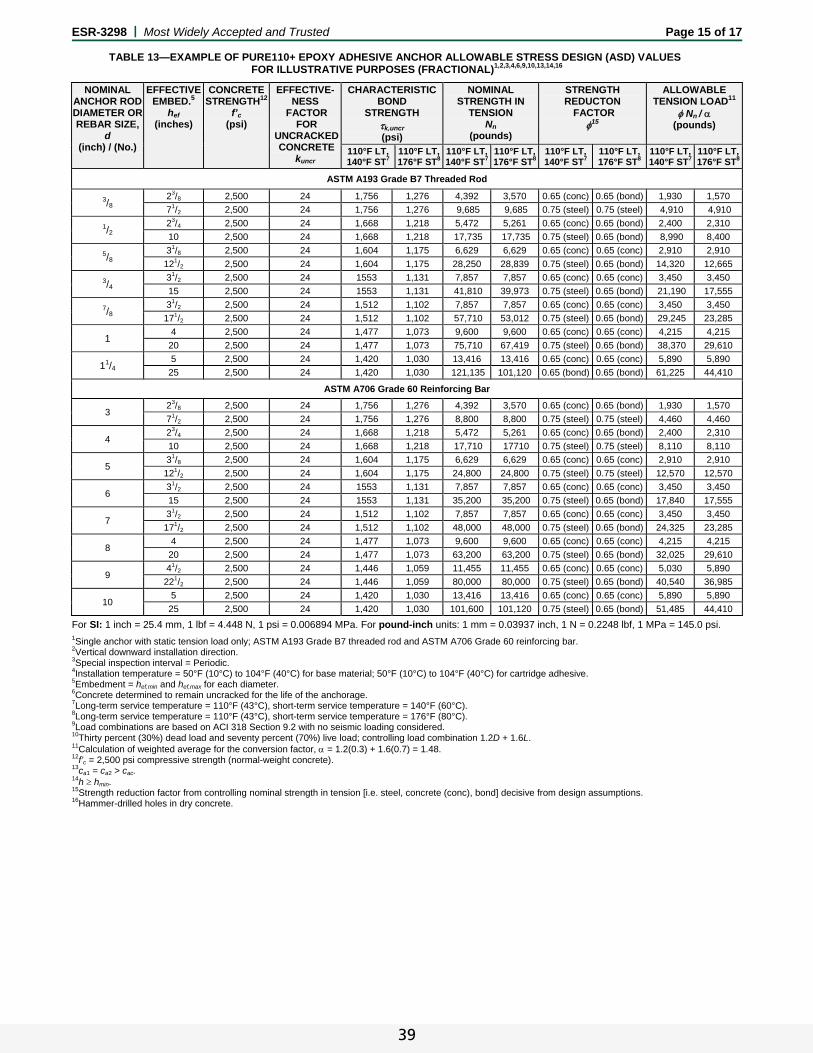
ESR-3298 | Most Widely Accepted and Trusted Page 15 of 17
TABLE 13—EXAMPLE OF PURE110+ EPOXY ADHESIVE ANCHOR ALLOWABLE STRESS DESIGN (ASD) VALUES FOR ILLUSTRATIVE PURPOSES (FRACTIONAL)1,2,3,4,6,9,10,13,14,16
NOMINAL ANCHOR ROD DIAMETER OR REBAR SIZE,
d (inch) / (No.)
EFFECTIVE EMBED.5
hef (inches)
CONCRETE STRENGTH12
f’c (psi)
EFFECTIVE-NESS
FACTOR FOR
UNCRACKED CONCRETE
kuncr
CHARACTERISTICBOND
STRENGTH k,uncr (psi)
NOMINAL STRENGTH IN
TENSION Nn
(pounds)
STRENGTH REDUCTON
FACTOR 15
ALLOWABLE TENSION LOAD11
Nn / (pounds)
110°F LT, 140°F ST7
110°F LT,176°F ST8
110°F LT,140°F ST7
110°F LT,176°F ST8
110°F LT, 140°F ST7
110°F LT, 176°F ST8
110°F LT,140°F ST7
110°F LT,176°F ST8
ASTM A193 Grade B7 Threaded Rod
3/8 23/8 2,500 24 1,756 1,276 4,392 3,570 0.65 (conc) 0.65 (bond) 1,930 1,570
71/2 2,500 24 1,756 1,276 9,685 9,685 0.75 (steel) 0.75 (steel) 4,910 4,910
1/2 23/4 2,500 24 1,668 1,218 5,472 5,261 0.65 (conc) 0.65 (bond) 2,400 2,310
10 2,500 24 1,668 1,218 17,735 17,735 0.75 (steel) 0.65 (bond) 8,990 8,400
5/8 31/8 2,500 24 1,604 1,175 6,629 6,629 0.65 (conc) 0.65 (conc) 2,910 2,910
121/2 2,500 24 1,604 1,175 28,250 28,839 0.75 (steel) 0.65 (bond) 14,320 12,665
3/4 31/2 2,500 24 1553 1,131 7,857 7,857 0.65 (conc) 0.65 (conc) 3,450 3,450
15 2,500 24 1553 1,131 41,810 39,973 0.75 (steel) 0.65 (bond) 21,190 17,555
7/8 31/2 2,500 24 1,512 1,102 7,857 7,857 0.65 (conc) 0.65 (conc) 3,450 3,450
171/2 2,500 24 1,512 1,102 57,710 53,012 0.75 (steel) 0.65 (bond) 29,245 23,285
1 4 2,500 24 1,477 1,073 9,600 9,600 0.65 (conc) 0.65 (conc) 4,215 4,215
20 2,500 24 1,477 1,073 75,710 67,419 0.75 (steel) 0.65 (bond) 38,370 29,610
11/4 5 2,500 24 1,420 1,030 13,416 13,416 0.65 (conc) 0.65 (conc) 5,890 5,890
25 2,500 24 1,420 1,030 121,135 101,120 0.65 (bond) 0.65 (bond) 61,225 44,410
ASTM A706 Grade 60 Reinforcing Bar
3 23/8 2,500 24 1,756 1,276 4,392 3,570 0.65 (conc) 0.65 (bond) 1,930 1,570
71/2 2,500 24 1,756 1,276 8,800 8,800 0.75 (steel) 0.75 (steel) 4,460 4,460
4 23/4 2,500 24 1,668 1,218 5,472 5,261 0.65 (conc) 0.65 (bond) 2,400 2,310
10 2,500 24 1,668 1,218 17,710 17710 0.75 (steel) 0.75 (steel) 8,110 8,110
5 31/8 2,500 24 1,604 1,175 6,629 6,629 0.65 (conc) 0.65 (conc) 2,910 2,910
121/2 2,500 24 1,604 1,175 24,800 24,800 0.75 (steel) 0.75 (steel) 12,570 12,570
6 31/2 2,500 24 1553 1,131 7,857 7,857 0.65 (conc) 0.65 (conc) 3,450 3,450
15 2,500 24 1553 1,131 35,200 35,200 0.75 (steel) 0.65 (bond) 17,840 17,555
7 31/2 2,500 24 1,512 1,102 7,857 7,857 0.65 (conc) 0.65 (conc) 3,450 3,450
171/2 2,500 24 1,512 1,102 48,000 48,000 0.75 (steel) 0.65 (bond) 24,325 23,285
8 4 2,500 24 1,477 1,073 9,600 9,600 0.65 (conc) 0.65 (conc) 4,215 4,215
20 2,500 24 1,477 1,073 63,200 63,200 0.75 (steel) 0.65 (bond) 32,025 29,610
9 41/2 2,500 24 1,446 1,059 11,455 11,455 0.65 (conc) 0.65 (conc) 5,030 5,890
221/2 2,500 24 1,446 1,059 80,000 80,000 0.75 (steel) 0.65 (bond) 40,540 36,985
10 5 2,500 24 1,420 1,030 13,416 13,416 0.65 (conc) 0.65 (conc) 5,890 5,890
25 2,500 24 1,420 1,030 101,600 101,120 0.75 (steel) 0.65 (bond) 51,485 44,410
For SI: 1 inch = 25.4 mm, 1 lbf = 4.448 N, 1 psi = 0.006894 MPa. For pound-inch units: 1 mm = 0.03937 inch, 1 N = 0.2248 lbf, 1 MPa = 145.0 psi.
1Single anchor with static tension load only; ASTM A193 Grade B7 threaded rod and ASTM A706 Grade 60 reinforcing bar. 2Vertical downward installation direction. 3Special inspection interval = Periodic. 4Installation temperature = 50°F (10°C) to 104°F (40°C) for base material; 50°F (10°C) to 104°F (40°C) for cartridge adhesive. 5Embedment = hef,min and hef,max for each diameter. 6Concrete determined to remain uncracked for the life of the anchorage. 7Long-term service temperature = 110°F (43°C), short-term service temperature = 140°F (60°C). 8Long-term service temperature = 110°F (43°C), short-term service temperature = 176°F (80°C). 9Load combinations are based on ACI 318 Section 9.2 with no seismic loading considered. 10Thirty percent (30%) dead load and seventy percent (70%) live load; controlling load combination 1.2D + 1.6L. 11Calculation of weighted average for the conversion factor, = 1.2(0.3) + 1.6(0.7) = 1.48. 12f’c = 2,500 psi compressive strength (normal-weight concrete). 13ca1 = ca2 > cac.
14h hmin. 15Strength reduction factor from controlling nominal strength in tension [i.e. steel, concrete (conc), bond] decisive from design assumptions. 16Hammer-drilled holes in dry concrete.
39

ESR-3298 | Most Widely Accepted and Trusted Page 16 of 17
FIGURE 3—MANUFACTURER’S PUBLISHED INSTALLATION INSTRUCTIONS (MPII)
40

ESR-3298 | Most Widely Accepted and Trusted Page 17 of 17
FIGURE 3—MANUFACTURER’S PUBLISHED INSTALLATION INSTRUCTIONS (MPII) (Continued)
41
ICC-ES Evaluation Reports are not to be construed as representing aesthetics or any other attributes not specifically addressed, nor are they to be construed as an endorsement of the subject of the report or a recommendation for its use. There is no warranty by ICC Evaluation Service, LLC, express or implied, as to any finding or other matter in this report, or as to any product covered by the report.
Copyright © 2015 Page 1 of 2 1000
ICC-ES Evaluation Report ESR-3298 FBC Supplement Reissued July 2014 This report is subject to renewal July 2015.
www.icc-es.org | (800) 423-6587 | (562) 699-0543 A Subsidiary of the International Code Council ®
DIVISION: 03 00 00—CONCRETE Section: 03 16 00—Concrete Anchors DIVISION: 05 00 00—METALS Section: 05 05 19—Post-Installed Concrete Anchors REPORT HOLDER: POWERS FASTENERS, INC. 701 EAST JOPPA ROAD TOWSON, MARYLAND 21286 (800) 524-3244 www.powers.com [email protected] EVALUATION SUBJECT: POWERS PURE110+ EPOXY ADHESIVE ANCHOR SYSTEM IN CRACKED AND UNCRACKED CONCRETE 1.0 REPORT PURPOSE AND SCOPE
Purpose:
The purpose of this evaluation report supplement is to indicate that the Powers Pure110+ Epoxy Adhesive Anchor System in Cracked and Uncracked Concrete, recognized in ICC-ES master evaluation report ESR-3298, has also been evaluated for compliance with the codes noted below.
Applicable code editions:
2010 Florida Building Code—Building
2010 Florida Building Code—Residential
2.0 CONCLUSIONS
The Powers Pure110+ Epoxy Adhesive Anchor System in Cracked and Uncracked Concrete, described in Sections 2.0 through 7.0 of the master evaluation report ESR-3298, complies with the 2010 Florida Building Code—Building and the 2010 Florida Building Code—Residential, provided the design and installation are in accordance with the International Building Code® provisions noted in the master report, and under the following conditions:
Design wind loads must be based on Section 1609 of the 2010 Florida Building Code—Building or Section 301.2.1.1 of the 2010 Florida Building Code—Residential, as applicable.
Load combinations must be in accordance with Section 1605.2 or Section 1605.3 of the 2010 Florida Building Code—Building, as applicable.
The modifications to ACI 318 as shown in 2009 IBC Sections 1908.1.9 and 1908.1.10, as noted in 2009 IBC Section 1912.1, do not apply to the 2010 Florida Building Code.
Use of the Powers Pure110+ epoxy adhesive anchors with stainless steel threaded rod materials and reinforcing bars has also been found to be in compliance with the High-Velocity Hurricane Zone provisions of the 2010 Florida Building Code—Building and the 2010 Florida Building Code—Residential, when the following conditions are met:
Design wind loads for use of the anchors in a High-Velocity Hurricane Zone must be based on Section 1620 of the Florida Building Code—Building.
Reinforcing bars must be in accordance with Section 1922.4 of the Florida Building Code—Building.
Use of the Powers Pure110+ epoxy adhesive anchors with carbon steel threaded rod materials for compliance with the High-Velocity Hurricane Zone provisions of the 2010 Florida Building Code—Building and the 2010 Florida Building Code—Residential has not been evaluated, and is outside the scope of this supplemental report.
42

ESR-3298 FBC Supplement | Most Widely Accepted and Trusted Page 2 of 2
For products falling under Florida Rule 9N-3, verification that the report holder’s quality assurance program is audited by a quality assurance entity approved by the Florida Building Commission for the type of inspections being conducted is the responsibility of an approved validation entity (or the code official when the report holder does not possess an approval by the Commission).
This supplement expires concurrently with the master report reissued July 2014, revised January 2015.
43

Date printed 18.12.2013, Revision 11.04.2013 Version 01 Page 1 / 7
Powers Fasteners, Inc.
Safety Data Sheet (SDS) conforms to ANSI Z400.1/Z129.1-2010 (29 CFR 1910) (US)
PURE 110+ Component A
Brewster, NY 10509
SECTION 1: Identification of the substance / preparation and of the company
Product identifier PURE 110+ Component ARelevant identified uses of the substance or mixture and uses advised against
Adhesive mortar for fastening elements A-Component (Resin)
Identified use none
Company Powers Fasteners, Inc.2 Powers LaneBrewster, NY 10509 / USAPhone +1 800-524-3244Fax +1 877-871-1965
Address enquiries to
Emergency phone Advisory body CHEMTREC: +1 703-741-5500 (24h) (Emergency Contact Information Only) USA: 800-424-9300
SECTION 2: Hazards identification
Emergency Overview
Appearance, Odor: pasty, light beige, characteristic
WARNING
CAUSES EYE AND SKIN IRRITATION.MAY CAUSE ALLERGIC SKIN REACTION.HARMFUL TO AQUATIC LIFE WITH LONG LASTING EFFECTS.MAY CAUSE RESPIRATORY TRACT IRRITATION.
OSHA Regulatory Status This product is classified as hazardous in accordance to OSHA Standard 29 CFR 1910.1200.
Potential health effects People who are allergic to epoxide should avoid the use of the product.
Potential environmental effects
SECTION 3: Composition / Information on ingredients
The product is a mixture.
Range [%] Substance
30 - 40CAS: 9003-36-5Reaction product: bisphenol-F-(epichlorhydrin) Epoxy resin (number average molecular weight ≤ 700)
20 - 30CAS: 25068-38-6Reaction product: bisphenol-A-(epichlorhydrin) Epoxy resin (number average molecular weight ≤ 700)
1 - <10CAS: 30499-70-8Trimethylolpropane triglycidyl ether
1 - <10CAS: 9003-36-5Reaction product: bisphenol-F-(epichlorhydrin) Epoxy resin (number average molecular weight ≤ 700)
5 - <10 Zubereitung
Comment on component parts Substances of Very High Concern - SVHC: substances are not contained or are below 0,1%.For full text of H-statements and R-phrases: see SECTION 16.
SECTION 4: First aid measures
Description of first aid measures Change soaked clothing immediately.
Inhalation Ensure supply of fresh air.In the event of symptoms seek for medical treatment.
Skin contact In case of contact with skin wash off immediately with soap and water.Consult a doctor if skin irritation persists.
Eye contact Rinse cautiously with water for several minutes. Remove contact lenses, if present and easy to do. Continue rinsing.If eye irritation persists: Get medical advice/attention.
Ingestion Supply with medical care.Rinse out mouth and give plenty of water to drink.
Indication of any immediate medical attention and special treatment needed
Treat symptomatically.Forward this sheet to the doctor.
US
44

Date printed 18.12.2013, Revision 11.04.2013 Version 01 Page 2 / 7
Powers Fasteners, Inc.
Safety Data Sheet (SDS) conforms to ANSI Z400.1/Z129.1-2010 (29 CFR 1910) (US)
PURE 110+ Component A
Brewster, NY 10509
SECTION 5: Fire-fighting measures
Suitable extinguishing media foam, dry powder, water spray jet, carbon dioxide
Extinguishing media that must not be used Full water jet
Special exposure hazards arising from the substance or preparation itself or combustion products
Unknown risk of formation of toxic pyrolysis products.Carbon monoxide (CO)Chlorine compounds.
Special protective equipment for firefighters
Do not inhale explosion and/or combustion gases.Use self-contained breathing apparatus.
Additional information Fire residues and contaminated firefighting water must be disposed of in accordance within the local regulations.Collect contaminated firefighting water separately, must not be discharged into the drains.
SECTION 6: Accidental release measures
Personal precautions, protective equipment and emergency procedures
Ensure adequate ventillation.Use personal protective equipment.High risk of slipping due to leakage/spillage of product.
Environmental precautions Do not discharge into the drains/surface waters/groundwater.In case the product spills into drains/surface waters/groundwater, immediately inform the authorities.
Methods and material for containment and cleaning up
Take up mechanically.Take up residues with absorbent material (e.g. sand, sawdust, generalpurpose binder, diatomaceous earth).Dispose of absorbed material in accordance within the regulations.
SECTION 7: Handling and storage
Precautions for safe handling Use only in well-ventilated areas.
Advice on protection against fire and explosion
Keep away from all sources of ignition - Refrain from smoking.Take precautionary measures against static discharges.
Requirements for storage rooms and vessels
Keep only in original container.Prevent penetration into the ground.
Advice on storage compatibility Do not store together with food and animal food/diet.
Further information on storage conditions Keep container in a well-ventilated place.Keep container tightly closed.Keep in a cool place. Store in a dry place.Protect from atmospheric moisture and water.Recommended storage temperature: 5-25 °C (41-77 °F).
SECTION 8: Exposure controls / personal protection
Additional advice on system design Ensure adequate ventilation on workstation.
Ingredients with occupational exposure limits to be monitored (US)
not applicable
Respiratory protection If ventilation insufficient, wear respiratory protection.Short term: filter apparatus, combination filter A-P2.
Hand protection The details concerned are recommendations. Please contact the glove supplier for further information.Nitrile rubber, >480 min (EN 374).
Eye protection Tightly fitting goggles.
Skin protection Protective clothing.
General protective measures Avoid contact with eyes and skin.Do not inhale gases/vapours/aerosols.Personal protective equipment should be selected specifically for the working place, depending on concentration and quantity of the hazardous substances handled. The resistance of these equipments to chemicals should be ascertained with the respective supplier.
Hygiene measures Wash hands before breaks and after work.Use barrier skin cream.Take off contaminated clothing and wash before reuse.Do not eat, drink or smoke when using this product.
Delimitation and monitoring of the environmental exposition
See SECTION 6+7.
US
45

Date printed 18.12.2013, Revision 11.04.2013 Version 01 Page 3 / 7
Powers Fasteners, Inc.
Safety Data Sheet (SDS) conforms to ANSI Z400.1/Z129.1-2010 (29 CFR 1910) (US)
PURE 110+ Component A
Brewster, NY 10509
SECTION 9: Physical and chemical properties
Form pasty
Color light beige
Odor characteristic
pH-value not applicable
pH-value [1%] not applicable
Boiling point [°C] not determined
Flash point [°C] not applicable
Flammability [°C] not determined
Lower explosion limit not determined
Upper explosion limit not determined
Oxidizing properties not determined
Vapour pressure/gas pressure [kPa] not determined
Density [g/ml] 1,33 (23°C / 73,4°F)
Bulk density [kg/m³] not applicable
Solubility in water insoluble
Partition coefficient [n-octanol/water] not determined
Viscosity not determined
Relative vapour density determined in air not determined
Evaporation speed not determined
Melting point [°C] not determined
Autoignition temperature [°C] not determined
Decomposition temperature [°C] not determined
SECTION 10: Stability and reactivity
Reactivity No dangerous reactions known if used as directed.
Chemical stability Stable under normal ambient conditions (ambient temperature).
Possibility of hazardous reactions Reactions with oxidizing agents.Reactions with alkalies, amines and strong acids.Reactions with alcohols.
Conditions to avoid See SECTION 7.2.
Incompatible materials See SECTION 10.3.
Hazardous decomposition products No hazardous decomposition products known.
US
46
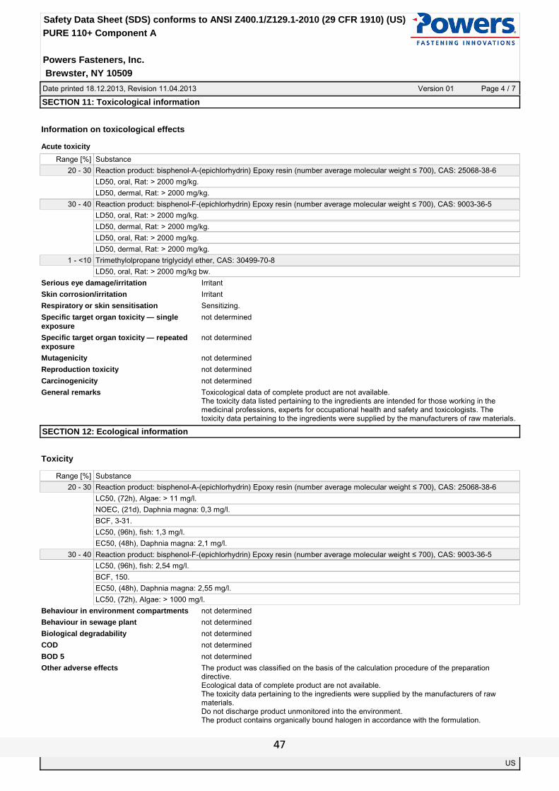
Date printed 18.12.2013, Revision 11.04.2013 Version 01 Page 4 / 7
Powers Fasteners, Inc.
Safety Data Sheet (SDS) conforms to ANSI Z400.1/Z129.1-2010 (29 CFR 1910) (US)
PURE 110+ Component A
Brewster, NY 10509
SECTION 11: Toxicological information
Information on toxicological effects
Acute toxicity
Range [%] Substance
20 - 30 Reaction product: bisphenol-A-(epichlorhydrin) Epoxy resin (number average molecular weight ≤ 700), CAS: 25068-38-6
LD50, oral, Rat: > 2000 mg/kg.
LD50, dermal, Rat: > 2000 mg/kg.
30 - 40 Reaction product: bisphenol-F-(epichlorhydrin) Epoxy resin (number average molecular weight ≤ 700), CAS: 9003-36-5
LD50, oral, Rat: > 2000 mg/kg.
LD50, dermal, Rat: > 2000 mg/kg.
LD50, oral, Rat: > 2000 mg/kg.
LD50, dermal, Rat: > 2000 mg/kg.
1 - <10 Trimethylolpropane triglycidyl ether, CAS: 30499-70-8
LD50, oral, Rat: > 2000 mg/kg bw.
Serious eye damage/irritation Irritant
Skin corrosion/irritation Irritant
Respiratory or skin sensitisation Sensitizing.
Specific target organ toxicity — single exposure
not determined
Specific target organ toxicity — repeated exposure
not determined
Mutagenicity not determined
Reproduction toxicity not determined
Carcinogenicity not determined
General remarks Toxicological data of complete product are not available.The toxicity data listed pertaining to the ingredients are intended for those working in the medicinal professions, experts for occupational health and safety and toxicologists. The toxicity data pertaining to the ingredients were supplied by the manufacturers of raw materials.
SECTION 12: Ecological information
Toxicity
Range [%] Substance
20 - 30 Reaction product: bisphenol-A-(epichlorhydrin) Epoxy resin (number average molecular weight ≤ 700), CAS: 25068-38-6
LC50, (72h), Algae: > 11 mg/l.
NOEC, (21d), Daphnia magna: 0,3 mg/l.
BCF, 3-31.
LC50, (96h), fish: 1,3 mg/l.
EC50, (48h), Daphnia magna: 2,1 mg/l.
30 - 40 Reaction product: bisphenol-F-(epichlorhydrin) Epoxy resin (number average molecular weight ≤ 700), CAS: 9003-36-5
LC50, (96h), fish: 2,54 mg/l.
BCF, 150.
EC50, (48h), Daphnia magna: 2,55 mg/l.
LC50, (72h), Algae: > 1000 mg/l.
Behaviour in environment compartments not determined
Behaviour in sewage plant not determined
Biological degradability not determined
COD not determined
BOD 5 not determined
Other adverse effects The product was classified on the basis of the calculation procedure of the preparation directive.Ecological data of complete product are not available.The toxicity data pertaining to the ingredients were supplied by the manufacturers of raw materials.Do not discharge product unmonitored into the environment.The product contains organically bound halogen in accordance with the formulation.
US
47

Date printed 18.12.2013, Revision 11.04.2013 Version 01 Page 5 / 7
Powers Fasteners, Inc.
Safety Data Sheet (SDS) conforms to ANSI Z400.1/Z129.1-2010 (29 CFR 1910) (US)
PURE 110+ Component A
Brewster, NY 10509
SECTION 13: Disposal considerations
Product Coordinate disposal with the disposal contractor/authorities if necessary.
Contaminated packaging Uncontaminated packaging may be taken for recycling.Dispose full / partially emptied cartridges as hazardous waste in accordance with official regulations.
RCRA Hazard Class (40CFR 261) Waste must be disposed of in accordance with federal, state and local environmental control regulations. Consult your local or regional authorities.
SECTION 14: Transport information
Transport by land according to ADR/RID UN 3077 Environmentally hazardous substance, solid, n.o.s. (Bisphenol A/F Epoxy resin) 9 III
- Classification Code M7
- Label
- ADR LQ 5 kg
- ADR 1.1.3.6 (8.6) Transport category (tunnel restriction code) 3 (E)
Inland navigation (ADN) UN 3077 Environmentally hazardous substance, solid, n.o.s. (Bisphenol A/F Epoxy resin) 9 III
- Classification Code M7
- Label
Marine transport in accordance with IMDG UN 3077 Environmentally hazardous substance, solid, n.o.s. (Bisphenol A/F Epoxy resin) 9 III MARINE POLLUTANT
- EMS F-A, S-F
- Label
- IMDG LQ 5 kg
Air transport in accordance with IATA UN 3077 Environmentally hazardous substance, solid, n.o.s. (Bisphenol A/F Epoxy resin) 9 III
- Label
DOT Road Shipment Information (49 CFR) UN/NA 3077 Environmentally hazardous substance, solid, n.o.s. (Bisphenol A/F Epoxy resin) 9 III
- Label
US
48

Date printed 18.12.2013, Revision 11.04.2013 Version 01 Page 6 / 7
Powers Fasteners, Inc.
Safety Data Sheet (SDS) conforms to ANSI Z400.1/Z129.1-2010 (29 CFR 1910) (US)
PURE 110+ Component A
Brewster, NY 10509
SECTION 15: Regulatory information
US Regulations
National regulations 29 CFR 1910.1200, ANSI Z400.1-2010, OSHA-PEL, ACGIH-TLV, NTP, IARC, SARA Title III, NFPA, TSCA, California - Prop. 65
- SARA, 302 not determined
- SARA, 311 This product is classified as hazardous under SARA 311.
- SARA, 313 Not determinated.
- CA Proposition 65 This product contains a substance known to the State of California to cause cancer. Silica, Quartz - CAS# 14808-60-7.
- TSCA All chemical substances in this material are included on or exempted from listing on the TSCA Inventory.
- FDA not applicable
American Conference of Governmental Industrial Hygienists - ACGIH
ACGIH: yes - contains crystalline silica
International Agency for Research on Cancer IARC
IARC: yes - contains crystalline silica.
National Toxicology Program - NTP This product is named NTP - National Toxicology Program (contains crystalline silica).This product is named NTP - National Toxicology Program (contains glycerol).
HAP-VOC
Transport-regulations DOT-Classification, ADR (2013); IMDG-Code (2013, 36. Amdt.); IATA-DGR (2013).
Other Right to Know Laws
EC Regulations
1967/548 (1999/45); 1991/689 (2001/118); 1999/13; 2004/42; 648/2004; 1907/2006 (Reach); 1272/2008; 75/324/EEC (2008/47/EC); 453/2010/EC
Hazard pictograms
Signal word WARNING
Contains: Reaction product: bisphenol-F-(epichlorhydrin) Epoxy resin (number average molecular weight ≤ 700) EINECS: 500-006-8
Reaction product: bisphenol-A-(epichlorhydrin) Epoxy resin (number average molecular weight ≤ 700) EINECS: 500-033-5
Trimethylolpropane triglycidyl ether, CAS: 30499-70-8
Hazard statements H315 Causes skin irritation.H319 Causes serious eye irritation.H317 May cause an allergic skin reaction.H411 Toxic to aquatic life with long lasting effects.
Precautionary statements P101 If medical advice is needed, have product container or label at hand.P102 Keep out of reach of children.P280 Wear protective gloves.P280 Wear eye protection/face protection.P333+P313 If skin irritation or rash occurs: Get medical advice/attention.P391 Collect spillage.P273 Avoid release to the environment.P501 Dispose of contents/container to in accordance with local/regional/national/international regulation.
Labelling
Hazard symbols
Irritant Dangerous for the environment
R-phrases R 36/38: Irritating to eyes and skin.R 43: May cause sensitisation by skin contact.R 51/53: Toxic to aquatic organisms, may cause long-term adverse effects in the aquatic environment.
S-phrases S 26: In case of contact with eyes, rinse immediately with plenty of water and seek medical advice.S 36/37/39: Wear suitable protective clothing, gloves and eye/face protection.S 51: Use only in well-ventilated areas.S 61: Avoid release to the environment. Refer to special instructions, safety data sheets.
Special labelling Contains epoxy-containing compounds. Observe manufacturer's instructions.
US
49

Date printed 18.12.2013, Revision 11.04.2013 Version 01 Page 7 / 7
Powers Fasteners, Inc.
Safety Data Sheet (SDS) conforms to ANSI Z400.1/Z129.1-2010 (29 CFR 1910) (US)
PURE 110+ Component A
Brewster, NY 10509
WARNING
Emergency Overview CAUSES EYE AND SKIN IRRITATION.MAY CAUSE ALLERGIC SKIN REACTION.HARMFUL TO AQUATIC LIFE WITH LONG LASTING EFFECTS.MAY CAUSE RESPIRATORY TRACT IRRITATION.
SECTION 16: Other information
Observe employment restrictions for people
yes
HMIS Ratings
HEALTH 2 - Moderate Hazard2
1 - Slight HazardFLAMMABILITY 1
1 - Slight HazardREACTIVITY 1
X - Personal protection rating to be supplied by user depending on use conditionsPERSONAL PROTECTION X
NFPA Ratings
1 TOP, FLAMMABILITY: 1 - Slight Hazard
12 LEFT, HEALTH: 2 - Moderate Hazard RIGHT, REACTIVITY: 1 - Slight Hazard
- BOTTOM, SPECIAL NOTICE: -
Modified position none
US
50

Date printed 18.12.2013, Revision 11.04.2013 Version 01 Page 1 / 8
Powers Fasteners, Inc.
Safety Data Sheet (SDS) conforms to ANSI Z400.1/Z129.1-2010 (29 CFR 1910) (US)
PURE 110+ Component B
Brewster, NY 10509
SECTION 1: Identification of the substance / preparation and of the company
Product identifier PURE 110+ Component BRelevant identified uses of the substance or mixture and uses advised against
Adhesive mortar for fastening elements” B-Component (Hardener)
Identified use none
Company Powers Fasteners, Inc.2 Powers LaneBrewster, NY 10509 / USAPhone +1 800-524-3244Fax +1 877-871-1965
Address enquiries to
Emergency phone Advisory body CHEMTREC: +1 703-527-3887 (24h) (Emergency Contact Information Only) USA: 800-424-9300
SECTION 2: Hazards identification
Emergency Overview
Appearance, Odor: pasty, red, amine-like
DANGER
CAUSES (SEVERE) EYE BURNS.CAUSES (SEVERE) SKIN BURNS.MAY CAUSE ALLERGIC SKIN REACTION.MAY CAUSE RESPIRATORY TRACT IRRITATION.
OSHA Regulatory Status This product is classified as hazardous in accordance to OSHA Standard 29 CFR 1910.1200.
Potential health effects People who are allergic to amines should avoid the use of the product.
Potential environmental effects
SECTION 3: Composition / Information on ingredients
The product is a mixture.
Range [%] Substance
20 - 30CAS: 57214-10-5Formaldehyde, oligomeric reaction products with phenol and m-phenylenebis(methylamine)
10 - <20 Zubereitung
1 - <5CAS: 1477-55-0m-Phenylenebis(methylamine)
3 - <5CAS: 108-95-2Phenol
1 - <5CAS: 90-72-22,4,6-Tris(dimethylaminomethyl)phenol
1 - <5CAS: 100-51-6Benzyl alcohol
Comment on component parts Substances of Very High Concern - SVHC: substances are not contained or are below 0,1%.For full text of H-statements and R-phrases: see SECTION 16.
US
51

Date printed 18.12.2013, Revision 11.04.2013 Version 01 Page 2 / 8
Powers Fasteners, Inc.
Safety Data Sheet (SDS) conforms to ANSI Z400.1/Z129.1-2010 (29 CFR 1910) (US)
PURE 110+ Component B
Brewster, NY 10509
SECTION 4: First aid measures
Description of first aid measures Remove contaminated soaked clothing immediately and dispose of safely.
Inhalation Remove the victim into fresh air and keep him calm.Seek medical advice immediately.
Skin contact In case of contact with skin wash off immediately with soap and water.Immediate medical treatment necessary, as untreated burns can result in slow-healing wounds.
Eye contact Rinse cautiously with water for several minutes. Remove contact lenses, if present and easy to do. Continue rinsing.Seek medical advice immediately.
Ingestion Do not induce vomiting.Seek medical advice immediately.Rinse out mouth and give plenty of water to drink.
Indication of any immediate medical attention and special treatment needed
Treat symptomatically.
SECTION 5: Fire-fighting measures
Suitable extinguishing media foam, dry powder, water spray jet, carbon dioxide
Extinguishing media that must not be used Full water jet
Special exposure hazards arising from the substance or preparation itself or combustion products
Unknown risk of formation of toxic pyrolysis products.Carbon monoxide (CO)Nitrogen oxides (NOx).
Special protective equipment for firefighters
Do not inhale explosion and/or combustion gases.Use self-contained breathing apparatus.Wear full protective suit.
Additional information Fire residues and contaminated firefighting water must be disposed of in accordance within the local regulations.Collect contaminated firefighting water separately, must not be discharged into the drains.
SECTION 6: Accidental release measures
Personal precautions, protective equipment and emergency procedures
Ensure adequate ventillation.Use personal protective equipment.High risk of slipping due to leakage/spillage of product.
Environmental precautions Do not discharge into the drains/surface waters/groundwater.In case the product spills into drains/surface waters/groundwater, immediately inform the authorities.
Methods and material for containment and cleaning up
Take up mechanically.Take up residues with absorbent material (e.g. sand, sawdust, generalpurpose binder, diatomaceous earth).Dispose of absorbed material in accordance within the regulations.
SECTION 7: Handling and storage
Precautions for safe handling Use only in well-ventilated areas.
Requirements for storage rooms and vessels
Keep only in original container.Prevent penetration into the ground.
Advice on storage compatibility Do not store together with food and animal food/diet.
Further information on storage conditions Keep container in a well-ventilated place.Keep container tightly closed.Keep in a cool place. Store in a dry place.Protect from atmospheric moisture and water.Recommended storage temperature: 5-25 °C (41-77 °F).
US
52

Date printed 18.12.2013, Revision 11.04.2013 Version 01 Page 3 / 8
Powers Fasteners, Inc.
Safety Data Sheet (SDS) conforms to ANSI Z400.1/Z129.1-2010 (29 CFR 1910) (US)
PURE 110+ Component B
Brewster, NY 10509
SECTION 8: Exposure controls / personal protection
Additional advice on system design Ensure adequate ventilation on workstation.
Ingredients with occupational exposure limits to be monitored (US)
Range [%] Substance
3 - <5 Phenol
CAS: 108-95-2, EINECS/ELINCS: 203-632-7, EU-INDEX: 604-001-00-2
Long-term exposure: 5 ppm, 19,2 mg/m³, ACGIH 2011, A4, IBE
10 - <20 Zubereitung
CAS: 108-95-2, EINECS/ELINCS: 203-632-7, EU-INDEX: 604-001-00-2
Long-term exposure: 5 ppm, 19,2 mg/m³, ACGIH 2011, A4, IBE
Respiratory protection If ventilation insufficient, wear respiratory protection.Short term: filter apparatus, combination filter A-P2.
Hand protection The details concerned are recommendations. Please contact the glove supplier for further information.Nitrile rubber, >480 min (EN 374).
Eye protection Tightly fitting goggles.
Skin protection Protective clothing.
General protective measures Avoid contact with eyes and skin.Do not inhale gases/vapours/aerosols.Personal protective equipment should be selected specifically for the working place, depending on concentration and quantity of the hazardous substances handled. The resistance of these equipments to chemicals should be ascertained with the respective supplier.
Hygiene measures Remove contaminated soaked clothing immediately and dispose of safely.Do not eat, drink, smoke or take drugs at work.Wash hands before breaks and after work.Use barrier skin cream.Showers and eye wash stations should be provided.
Delimitation and monitoring of the environmental exposition
See SECTION 6+7.
SECTION 9: Physical and chemical properties
Form pasty
Color red
Odor amine-like
pH-value not applicable
pH-value [1%] not applicable
Boiling point [°C] not determined
Flash point [°C] not applicable
Flammability [°C] not determined
Lower explosion limit not determined
Upper explosion limit not determined
Oxidizing properties not determined
Vapour pressure/gas pressure [kPa] not determined
Density [g/ml] ~1,84
Bulk density [kg/m³] not applicable
Solubility in water partially miscible
Partition coefficient [n-octanol/water] not determined
Viscosity not determined
Relative vapour density determined in air not determined
Evaporation speed not determined
Melting point [°C] not determined
Autoignition temperature [°C] not determined
Decomposition temperature [°C] not determined
US
53

Date printed 18.12.2013, Revision 11.04.2013 Version 01 Page 4 / 8
Powers Fasteners, Inc.
Safety Data Sheet (SDS) conforms to ANSI Z400.1/Z129.1-2010 (29 CFR 1910) (US)
PURE 110+ Component B
Brewster, NY 10509
SECTION 10: Stability and reactivity
Reactivity No dangerous reactions known if used as directed.
Chemical stability Stable under normal ambient conditions (ambient temperature).
Possibility of hazardous reactions Reactions with oxidizing agents.Reactions with strong acids.Reactions with epoxides
Conditions to avoid See SECTION 7.2.
Incompatible materials See SECTION 10.3.Copper and copper-bearing alloys
Hazardous decomposition products No hazardous decomposition products known.
SECTION 11: Toxicological information
Information on toxicological effects
Acute toxicity
Product
ATE-mix, dermal, Rat: > 2000 mg/kg.
ATE-mix, oral, Rat: > 2000 mg/kg.
Range [%] Substance
1 - <5 Benzyl alcohol, CAS: 100-51-6
LC50, inhalative, Rat: 4,178 mg/l/4h (OECD TG 403).
LD50, dermal, Rabbit: 2000 mg/kg bw (RTECS).
LC50, inhalative, Rat: 8,8 mg/l (4h) (IUCLID).
LD50, oral, Rat: 1230 mg/kg bw (IUCLID).
1 - <5 m-Phenylenebis(methylamine), CAS: 1477-55-0
LD50, dermal, Rabbit: ~ 2000 mg/kg (IUCLID).
LC50, inhalative, Rat: 2,4-mg/l/4h (Lit.).
LD50, oral, Rat: 930 mg/kg (IUCLID).
LC50, inhalative, Rat: ~ 700 ppm 1h (IUCLID).
3 - <5 Phenol, CAS: 108-95-2
LD50, oral, Rat: 317 mg/kg (Lit.).
LD50, dermal, Rat: 525-714 mg/kg (Lit.).
LC50, inhalative, Rat: 316 mg/l (4h) (Lit.).
Serious eye damage/irritation Product is caustic.
Skin corrosion/irritation Product is caustic.
Respiratory or skin sensitisation Sensitizing.
Specific target organ toxicity — single exposure
not determined
Specific target organ toxicity — repeated exposure
not determined
Mutagenicity not determined
Reproduction toxicity not determined
Carcinogenicity not determined
General remarks The product was classified on the basis of the calculation procedure of the preparation directive.The toxicity data listed pertaining to the ingredients are intended for those working in the medicinal professions, experts for occupational health and safety and toxicologists. The toxicity data pertaining to the ingredients were supplied by the manufacturers of raw materials.
US
54

Date printed 18.12.2013, Revision 11.04.2013 Version 01 Page 5 / 8
Powers Fasteners, Inc.
Safety Data Sheet (SDS) conforms to ANSI Z400.1/Z129.1-2010 (29 CFR 1910) (US)
PURE 110+ Component B
Brewster, NY 10509
SECTION 12: Ecological information
Toxicity
Range [%] Substance
1 - <5 Benzyl alcohol, CAS: 100-51-6
EC50, Bacteria: 71,4 mg/l (0,5 h) (IUCLID).
EC50, (24h), Daphnia magna: 400 mg/l (IUCLID).
LC50, (96h), Lepomis macrochirus: 10 mg/l (IUCLID).
1 - <5 m-Phenylenebis(methylamine), CAS: 1477-55-0
LC50, fish: 130 mg/l (Lit.).
EC10, Bacteria: 90 mg/l (Lit.).
3 - <5 Phenol, CAS: 108-95-2
EC50, (48h), Daphnia magna: 4,2 mg/l (Lit.).
IC50, (96h), Algae: 150 mg/l (Lit.).
LC50, (96h), Oncorhynchus mykiss: 5 mg/l (Lit.).
Behaviour in environment compartments not determined
Behaviour in sewage plant not determined
Biological degradability not determined
COD not determined
BOD 5 not determined
Other adverse effects The product was classified on the basis of the calculation procedure of the preparation directive.Ecological data of complete product are not available.The toxicity data pertaining to the ingredients were supplied by the manufacturers of raw materials.Do not discharge product unmonitored into the environment.
SECTION 13: Disposal considerations
Product Coordinate disposal with the disposal contractor/authorities if necessary.
Contaminated packaging Uncontaminated packaging may be taken for recycling.Dispose full / partially emptied cartridges as hazardous waste in accordance with official regulations.
RCRA Hazard Class (40CFR 261) Waste must be disposed of in accordance with federal, state and local environmental control regulations. Consult your local or regional authorities.
US
55

Date printed 18.12.2013, Revision 11.04.2013 Version 01 Page 6 / 8
Powers Fasteners, Inc.
Safety Data Sheet (SDS) conforms to ANSI Z400.1/Z129.1-2010 (29 CFR 1910) (US)
PURE 110+ Component B
Brewster, NY 10509
SECTION 14: Transport information
Transport by land according to ADR/RID UN 3259 Amines, solid, corrosive, n.o.s. (m-Phenylenebis(methylamine)) 8 II
- Classification Code C8
- Label
- ADR LQ 1 kg
- ADR 1.1.3.6 (8.6) Transport category (tunnel restriction code) 2 (E)
Inland navigation (ADN) UN 3259 Amines, solid, corrosive, n.o.s. (m-Phenylenebis(methylamine)) 8 II
- Classification Code C8
- Label
Marine transport in accordance with IMDG UN 3259 Amines, solid, corrosive, n.o.s. (m-Phenylenebis(methylamine)) 8 II
- EMS F-A, S-B
- Label
- IMDG LQ 1 kg
Air transport in accordance with IATA UN 3259 Amines, solid, corrosive, n.o.s. (m-Phenylenebis(methylamine)) 8 II
- Label
DOT Road Shipment Information (49 CFR) UN/NA 3259 Amines, solid, corrosive, n.o.s. (m-Phenylenebis(methylamine)) 8 II
- Label
US
56

Date printed 18.12.2013, Revision 11.04.2013 Version 01 Page 7 / 8
Powers Fasteners, Inc.
Safety Data Sheet (SDS) conforms to ANSI Z400.1/Z129.1-2010 (29 CFR 1910) (US)
PURE 110+ Component B
Brewster, NY 10509
SECTION 15: Regulatory information
US Regulations
National regulations 29 CFR 1910.1200, ANSI Z400.1-2010, OSHA-PEL, ACGIH-TLV, NTP, IARC, SARA Title III, NFPA, TSCA, California - Prop. 65
- SARA, 302 This product is classified as hazardous under SARA 302.
- SARA, 311 This product is classified as hazardous under SARA 311.
- SARA, 313 One or some ingredient(s) are listed under this regulation.
- CA Proposition 65 This product contains crystalline silica known to the State of California to cause cancer.
- TSCA All chemical substances in this material are included on or exempted from listing on the TSCA Inventory.
- FDA not applicable
American Conference of Governmental Industrial Hygienists - ACGIH
not determined
International Agency for Research on Cancer IARC
IARC: Contains one substance Group 3: Not classifiable as to carcinogenicity to humans.
National Toxicology Program - NTP This product is named NTP - National Toxicology Program (contains crystalline silica).This product is named NTP - National Toxicology Program (contains Phenol).This product is named NTP - National Toxicology Program (contains Benzyl alcohol).
HAP-VOC not applicable
Transport-regulations DOT-Classification, ADR (2013); IMDG-Code (2013, 36. Amdt.); IATA-DGR (2013).
Other Right to Know Laws
EC Regulations
1967/548 (1999/45); 1991/689 (2001/118); 1999/13; 2004/42; 648/2004; 1907/2006 (Reach); 1272/2008; 75/324/EEC (2008/47/EC); 453/2010/EC
Hazard pictograms
Signal word DANGER
Contains: Formaldehyde, oligomeric reaction products with phenol and m-phenylenebis(methylamine) EINECS: 500-137-0
Phenol EINECS: 203-632-7
m-Phenylenebis(methylamine) EINECS: 216-032-5
2,4,6-Tris(dimethylaminomethyl)phenol EINECS: 202-013-9
Hazard statements H314 Causes severe skin burns and eye damage.H317 May cause an allergic skin reaction.H341 Suspected of causing genetic defects.
Precautionary statements P101 If medical advice is needed, have product container or label at hand.P102 Keep out of reach of children.P201 Obtain special instructions before use.P260 Do not breathe vapours.P280 Wear protective gloves/protective clothing/eye protection/face protection.P281 Use personal protective equipment as required.P301+P330+P331 IF SWALLOWED: rinse mouth. Do NOT induce vomiting.P303+P361+P353 IF ON SKIN (or hair): Remove/Take off immediately all contaminated clothing. Rinse skin with water/shower.P305+P351+P338 IF IN EYES: Rinse cautiously with water for several minutes. Remove contact lenses, if present and easy to do. Continue rinsing.P308+P313 IF exposed or concerned: Get medical advice/attention.P310 Immediately call a POISON CENTER or doctor/physician.P333+P313 If skin irritation or rash occurs: Get medical advice/attention.P363 Wash contaminated clothing before reuse.P501 Dispose of contents/container to in accordance with local/regional/national/international regulation.Contains ~ 20 % of components with unknown hazards to the aquatic environment.
Labelling The product is classified and required to be labelled in accordance with EC-Directives
Hazard symbols
US
57
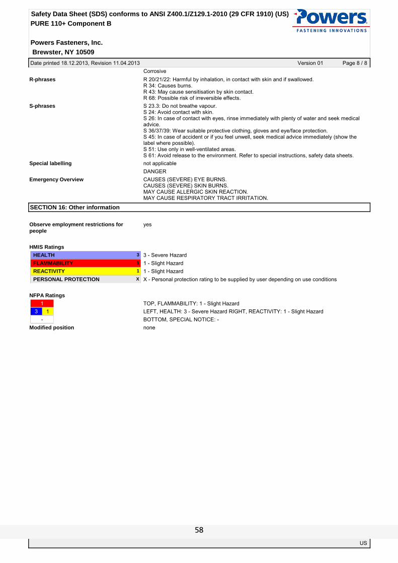
Date printed 18.12.2013, Revision 11.04.2013 Version 01 Page 8 / 8
Powers Fasteners, Inc.
Safety Data Sheet (SDS) conforms to ANSI Z400.1/Z129.1-2010 (29 CFR 1910) (US)
PURE 110+ Component B
Brewster, NY 10509
Corrosive
R-phrases R 20/21/22: Harmful by inhalation, in contact with skin and if swallowed.R 34: Causes burns.R 43: May cause sensitisation by skin contact.R 68: Possible risk of irreversible effects.
S-phrases S 23.3: Do not breathe vapour.S 24: Avoid contact with skin.S 26: In case of contact with eyes, rinse immediately with plenty of water and seek medical advice.S 36/37/39: Wear suitable protective clothing, gloves and eye/face protection.S 45: In case of accident or if you feel unwell, seek medical advice immediately (show the label where possible).S 51: Use only in well-ventilated areas.S 61: Avoid release to the environment. Refer to special instructions, safety data sheets.
Special labelling not applicable
DANGER
Emergency Overview CAUSES (SEVERE) EYE BURNS.CAUSES (SEVERE) SKIN BURNS.MAY CAUSE ALLERGIC SKIN REACTION.MAY CAUSE RESPIRATORY TRACT IRRITATION.
SECTION 16: Other information
Observe employment restrictions for people
yes
HMIS Ratings
HEALTH 3 - Severe Hazard3
1 - Slight HazardFLAMMABILITY 1
1 - Slight HazardREACTIVITY 1
X - Personal protection rating to be supplied by user depending on use conditionsPERSONAL PROTECTION X
NFPA Ratings
1 TOP, FLAMMABILITY: 1 - Slight Hazard
13 LEFT, HEALTH: 3 - Severe Hazard RIGHT, REACTIVITY: 1 - Slight Hazard
- BOTTOM, SPECIAL NOTICE: -
Modified position none
US
58