prof. dr.-ing. norbert vogt - hssmge of eurocode ec-7.pdf · 2012-04-03 · prof. dr.-ing. norbert...
TRANSCRIPT

Prof. Dr.-Ing. Norbert VogtChair of Foundation Engineering, Soil Mechanics, Rock Mechanics and Tunneling at the Technische Universität München
Implementation of Eurocode 1997-1in Germany in Connection with a new DIN 1054
Athens, march 16th, 2009

Based on presentations of B. Schuppener, N. Vogt und A. Weißenbach
Implementation of Eurocode 1997-1in Germany in Connection with
a new DIN 1054

• Introduction• Basic principle for the implementation
( Selection of values of partial factors)• Three design approaches of EC 7-1• Comparative design in an example• Conclusions of the comparative design
( German selection of approaches)• Handbook of codes: DIN EN 1997-1 and its National
Annex, which refers to a new DIN 1054
Implementation of Eurocode 7 in Germany

Basic principle for the implementation
The former DIN 1054 was introduced in 1976 and is mandatory in all German federal states.
Tradition, more than one generationValidated: thousands of foundation constructions
The safety level of the former global safety concept shall be maintained when adopting the concept of limit state design and partial factors of the Eurocode!

Design approaches of EC 7-1
Ed=E(γE>1)
Rd=R(γR= γϕ=1.0)
DA-1
Ed=E(γE=1)
Rd=R(γR=1; γϕ>1)
Combination 1
Combination 2
Ed=E(γE>1)
Rd=R(γR>1, γϕ=1)
DA-2
Ed=E(γE>1)
Rd=R(γR=1, γϕ>1)
DA-3

DA 2 and DA 2*
Ed=E(γE>1)
Rd=R(γR>1, γϕ=1)
bearing capacity is depending on- load inclination H/V- excentricity of loads e = M/V
R = R(H/V; M/V; …)
DA-2: Rd = 1/γR·Rk Rk = R( Hd/Vd; Md /Vd; …)
DA-2*: Rd = 1/γR·Rk Rk = R( Hk/Vk; Mk/Vk; …)
With DA 2* all verifications are done with characteristic values of effects of actionas far as possible.Application of partial factors to effects of action is the last step of verifications

MH,kHQ,k
VG,k
d
B = ? mDepth of the strip footing: d = 1,0 mPermanent vertical effect of action: VG,k = 400 kN/mVariable horizontal action: HQ,k gradually increasedVariable moment: MH,k = 4.0 ⋅ HkWeight density of the soil: γ1 = γ2 =19 kN/m³Angle of shearing resistance: ϕ´k = 32.5°partial factor for permanent/variable actions γG/Q = 1.35/1.50partial factor for bearing resistance γR;v = 1.40partial factor for sliding γR;h = 1.10
Example for a comparison of theDesign Approaches of EC 7-1

0.00
1.00
2.00
3.00
4.00
5.00
6.00
0 0.1 0.2 0.3
comb. 1: γG = 1.35: Vk unfavourablecomb. 1: γG,inf = 1.0: Vk favourable
WidthB [m]
HQ,k/VG,k
HQ,k/VG,k= 0.24sliding becomes
relevant
Design Approach DA 1
global: η = 2.00comb. 2: γϕ = 1.25, γQ = 1.30

0.00
1.00
2.00
3.00
4.00
5.00
6.00
0 0.1 0.2 0.3HQ,k/VG,k
WidthB [m]
Design Approach DA 2(partial factors applied to the actions at the
the beginning of the calculation )γG = 1.35: Vk unfavourableγG,inf = 1.0: Vk favourableGlobal: η = 2.0
HQ,k/VG,k= 0.24sliding becomes
relevant

Design Approach DA 2*(partial factors applied to effects of actions
at the end of the calculation)
0.00
1.00
2.00
3.00
4.00
5.00
6.00
WidthB [m]
0 0.1 0.2 0.3HQ,k/VG,k
HQ,k/VG,k= 0.24sliding becomes
relevant
γG = 1.35: Vk unfavourable
Global: η = 2.0γG,inf = 1.0: Vk favourable

0.00
1.00
2.00
3.00
4.00
5.00
6.00
7.00
0 0.1 0.2 0.3
γG = 1.35: Vk unfavourableγG,inf = 1.0: Vk favourableGlobal: η = 2.0
WidthB [m]
HQ,k/VG,k
Design Approach DA 3:
HQ,k/VG,k= 0.21sliding becomes
relevant
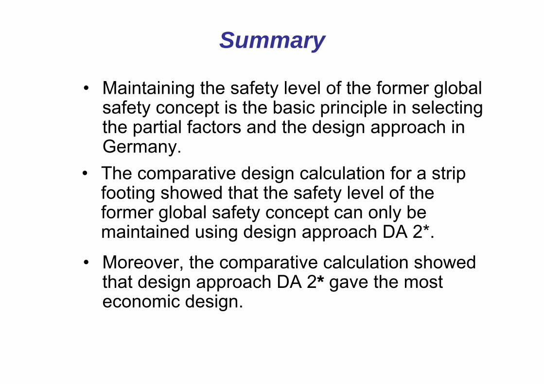
Summary
• The comparative design calculation for a strip footing showed that the safety level of the former global safety concept can only be maintained using design approach DA 2*.
• Maintaining the safety level of the former global safety concept is the basic principle in selecting the partial factors and the design approach in Germany.
• Moreover, the comparative calculation showed that design approach DA 2* gave the most economic design.

Selection of values of partial factors
EN 1990 gives the partial factors γF to be applied on actions and effects of action.
To maintain the same global safety factors η as in advance, suited design approaches have to be chosen and partial factors γR to be applied on resistances to obtain:
η = γF· γR

DIN1054:2005DIN EN 1997-1:2005
Specific German experiences:e.g. allowable
bearing pressure, pile resistances
Design approaches
which are notused in
Germany and informative annexes
Common Regulations:
e.g. Concept of limit states
and partial factors, geotechnicalcategories
DIN EN 1997-1:2005 and DIN 1054:2005
Relation between EN 1997-1 and national codes
• Text passages of EC 7-1 may not be changed, i.e. nothing can be deleted and amendments are notallowed
• Only at few distinguished points national choices canbe made using the national annex
• National codes will be allowed in the futurebut:
• National Codes may not be contradictory to European Codes and may not be competing

National Annex to EN 1997-1
The national Annex contains:
• Choices about design approaches to be applied• Regulations about the values of partial factors• Determinations about the use of informative annexesand • Links to non-contradictory additional informations, which
may help the user in applying the Eurocodes – especiallylinks to a new DIN 1054

Eurocode 7: Entwurf, Berechnung und Bemessung in der Geotechnik - Teil 1: Allgemeine Regeln;Deutsche Fassung EN 1997-1:2005
Nationaler Anhang zuEurocode 7: Entwurf, Berechnung und Bemessung in der Geotechnik - Teil 1: Allgemeine Regeln;Deutsche Fassung EN 1997-1:2005
National Annex
DIN EN 1997-1/NA
DIN EN 1997-1
Baugrund –Ergänzende Regelungen zu DIN EN 1997-1:2005-10, Eurocode 7: Entwurf, Berechnung und Bemessung in der Geotechnik - Teil 1: Allgemeine Regeln
Additional Regulations
DIN 1054

Normenhandbuch zu
DIN EN 1997-1: 2005-10Geotechnische
Bemessung - Allgemeine Regeln
und DIN 1054: 2009-xx
Ergänzende Regelungenzu DIN EN 1997-1
Handbook of Codes
(DIN) EN 1997-1
German Annex to(DIN) EN 1997-1
DIN 1054: 2009Additional regulationsin connection of DIN EN 1997-1

Black text in the middle: EC 7
Green text at left: National Annex
Red text at right: Additional Regulations

Geotechnical Categories (GK)
The Geotechnical Categories serve to determine minimal requirements with respect to
- Soil Investigation,- Calculations and analyses- Control and measurements during construction time
Definitions and examples are meanwhile harmonized in DIN 1054 und DIN 4020 (and other codes)
The identical annex: „Examples of characteristics to classify into Geotechnical Categories“ will be used withDIN 1054 (design) and DIN 4020 (Soil investigation).
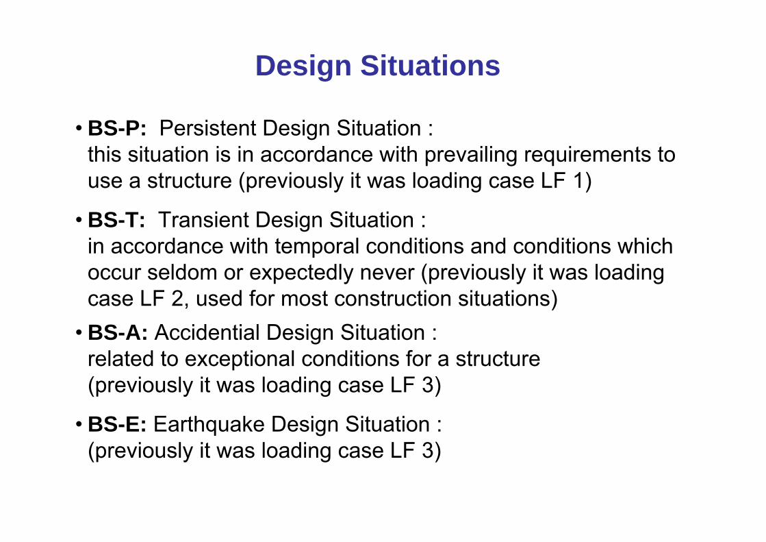
Design Situations
• BS-P: Persistent Design Situation :this situation is in accordance with prevailing requirements to use a structure (previously it was loading case LF 1)
• BS-T: Transient Design Situation :in accordance with temporal conditions and conditions whichoccur seldom or expectedly never (previously it was loadingcase LF 2, used for most construction situations)
• BS-A: Accidential Design Situation : related to exceptional conditions for a structure(previously it was loading case LF 3)
• BS-E: Earthquake Design Situation : (previously it was loading case LF 3)
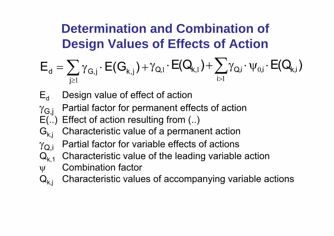
Determination and Combination of Design Values of Effects of Action
+⋅γ= ∑≥
)G(EE j,kj
j,Gd1
)Q(E)Q(E i,ki
i,i,Q,k,Q ⋅ψ⋅γ+⋅γ ∑>1
011
Ed Design value of effect of actionγG,j Partial factor for permanent effects of actionE(..) Effect of action resulting from (..)Gk,j Characteristic value of a permanent actionγQ,i Partial factor for variable effects of actionsQk,1 Characteristic value of the leading variable actionψ Combination factorQk,j Characteristic values of accompanying variable actions

∑≥
+⋅γ=1j
j,kj,Gd ""G(EE )∑>
⋅ψγ+⋅γ1
0111i
i,ki,,Q,k,Q Q""Q
Determination and Combination of Design Values of Effects of Action where superposition is not possible
„+“ „is to be combined “, Σ: „joint effect of “Ed Design value of effect of actionE(..) Effect of Action resulting from (..)γG,j Partial factor for permanent actionsGk,j Characteristic value of a permanent actionγQ Partial factor for variable actionsQk,1 Characteristic value of the leading variable actionψ Combination factorQk,i Characteristic values of accompanying variable actions

Limit States according to DIN 1054:2005
Three limit states with different use of partial factors
LS 1A: Partial factors only to be used on actions(to be used with overturning, uplift and buoying upwards)
LS 1B: Partial factors to be applied on effects of actionand resistances; ( to be used with verifications ofconstructions and parts of construction)
LS 1C: Partial factors to be applied on actions and onshear resistance (to be used with verifications ofslope stability and overall stability)

Limit States according to EN 1997-1
LS 1CGEO-3
Failure or excessive deformation of the ground, in which the strength of the ground is significant in providing resistance.
GEO-2
Internal failure of the structure or ist parts, in which the strength of structural materials issignificant in providing resistance.LS 1B
STR
Hydraulic heave, internal erosion and piping in the ground caused by hydraulic gradientsLS 1AHYD
Loss of equilibrium of the structure or the grounddue to uplift by water pressure (buoyancy) orother vertical actions.
LS 1AUPL
Loss of equilibrium of the structure or the ground, in which the strengths are insignificant in providing resistance.
LS 1AEQU
Limit State DIN 1054
DIN EN 1997-1

Partial Factors for Actions in Germany
1,001,10
1,301,50γQEffects of Action due to Variable Actions
1,001,10
1,201,35γGEffects of Action due to Permanent Actions
Failure of Stuctures and Ground (STR und GEO-2)
1,001,00
1,001,30
1,001,50
γQ,dstDestabilising Variable Actions
0,950,95
0,900,95
0,900,95
γG,stbStabilising Permanent Actions
1,001,00
1,001,05
1,001,05
γG,dstDestabilising Permanent ActionsHydraulic Failure and Uplift (buoyancy) (HYD and UPL)
(LF 3)BS-A
(LF 2)BS-T
(LF 1)BS-P
1054 oldnew
Action andEffects of Action

Design Situation
BS-P BS-T BS-A
GEO-3: Limit State by loss of overall stability
tan ϕ′ of drained soil; tan ϕu of undrained soil
cohäsion c′ of drained soil and shear strength cu of undrained soil
γϕ, γϕu
γc, γcu
1,25
1,25
1,15
1,15
1,10
1,10
Partial Factors for Soil Resistances

Design Situation Resistance
BS-P BS-T BS-A
STR und GEO-2: Limit state of failure of constructions, parts of construction and ground
Ground Resistance
earth pressure resistance and bearing resistance
Resistance against sliding
γR,e, γR;v
γR,h
1,40
1,10
1,30
1,10
1,20
1,10
Pile Resistance based on static and dynamic pile loading tests
Base Resistance
Shaft Resistance (Compression)
Total Resistance (Compression)
Shaft Resistance (Tension)
γb
γs
γt
γs,t
1,10
1,10
1,10
1,15
1,10
1,10
1,10
1,15
1,10
1,10
1,10
1,15
Pile Resistance based on Experience
Compression Piles
Tensile Piles (only in exceptional cases)
γb; γs; γt
γs,t
1,40
1,50
1,40
1,50
1,40
1,50
Pull-Out-Resistance
Soil-Nails and Rock-Nails
Bodies of grouted anchors
Flexible reinforcement elements
γa
γa
γa
1,40
1,10
1,40
1,30
1,10
1,30
1,20
1,10
1,20
Partial Factors for Resistances

Partial Factors for Pile Resistance
1,401,401,50
1,401,401,50
1,401,401,50
γb, γs, γtγs,t
Compresion PilesTensile Piles (only in exceptional cases)
Pile Resistance based on Experience
1,301,15
1,301,15
1,301,15
γs,tShaft Resistance(Tension)
1,201,10
1,201,10
1,201,10
γtTotal Resistance(Compression)
1,201,10
1,201,10
1,201,10
γsShaft Resistance(Compression)
1,201,10
1,201,10
1,201,10
γbBase ResistancePile Resistance based on static Pile Loading Tests
(LF 3)BS-A
(LF 2)BS-T
(LF 1)BS-P
1054 oldnew
Resistance
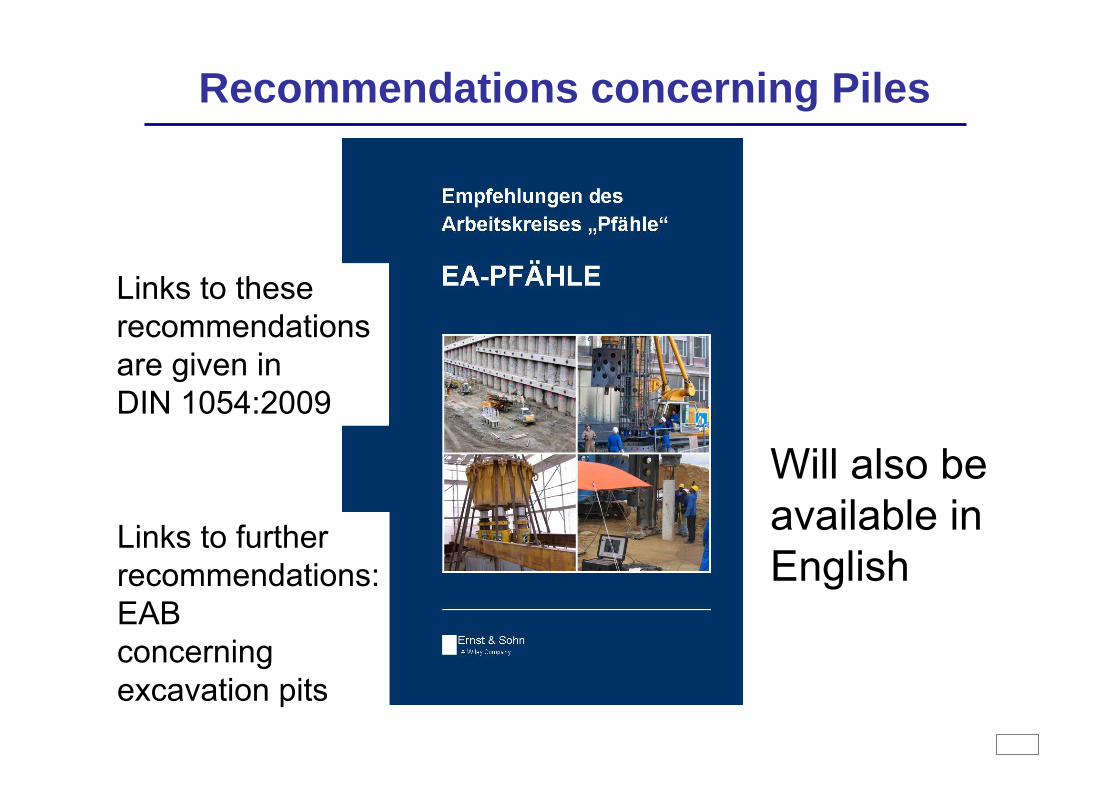
Recommendations concerning Piles
Will also beavailable inEnglish
Links to theserecommendationsare given inDIN 1054:2009
Links to furtherrecommendations:EABconcerningexcavation pits

Simplified Verification for Shallow Footings
Attention: the values are not allowable bearing pressures!
> 700300 bis 700120 bis 300Uniaxial Compressionstrength qu,k in kN/m2
5603902502,005003502201,504502902001,003902401700,50
Ic > 1.25Ic > 1.0Ic > 0.75mConsistency
Design Value of Bearing Resistance σR,dkN/m2Embedment depth
of the footing
Table A 6.7: Design Value of Bearing Resistance σR,d forStrip Foundations on Clay and Silt (UM, TL, TM)
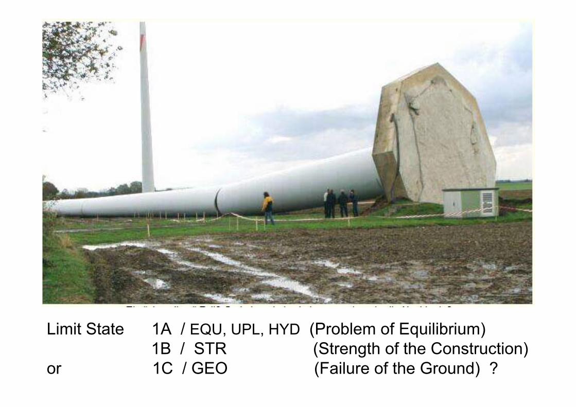
Limit State 1A / EQU, UPL, HYD (Problem of Equilibrium) 1B / STR (Strength of the Construction)
or 1C / GEO (Failure of the Ground) ?

Verification of Gap in Base Joint; : Mk = 80 · 7,0 = 560 kNmVk = 300 kN/mExcentricity: e = 560 / 300 = 1,87 mMaximum of Gap: Centre of footing: e < b/3 b/3 = 5,6 / 3 = 1,87 mVerification is ok
Gk = 300 kN
5,6 mOverturning related todestabilising: Mdst,Q,k = 80 · 7,0 = 560 kNmstabilising: Mstb,G,k = 300 ⋅ 2,8 = 840 kNm
Md,Q,dst = 1,50 ⋅ 560 = 840 kNmMd,G,stb = 0,90 · 840 = 756 kNm (< Md,Q,dst)
Verification is not ok. Footing must be enlarged.As the geometry of a footing can be determined by this verification,DIN 1054:2009 requires this verification, although overturning over an edgeis physically not possible: ground failure will occur before overturning
Overturning and Gap in Base JointHk = 80 kN
7,0
m
γQ,dst = 1,50γG,stb = 0,90

Verification of foundations withintensive excentric loading
VG,k
MQ,k
Global Safety against Overturning: η = 1,50 =
Limit State of Static Equilibrium EQU with γQ,dst = 1,50 and γG,stb= 0,90 η = γQ,dst / γG,stb = 1,67
Both verifications are necessary with DIN 1054:2009
b/3 b/2
b/3Vb/2V⋅⋅
e ≤ b/3

6,4 m
enlarged footing, B = 6,4 mVerification of overturning related to destabilising: Mdst,Q,k = 80 · 7,0 = 560 kNmstabilising: Mstb,G,k = 300 ⋅ 3,2 = 960 kNm
Md,Q,dst = 1,50 ⋅ 560 = 840 kNmMd,G,stb = 0,90 · 960 = 864 kNm (> Md,Q,dst)
Verification is ok.
Overturning and Verification of reinforced concrete structure of a footing
Hk = 80 kN
7,0
m
γQ,dst = 1,50γG,stb = 0,90γG,inf = 1,00(γG,sup = 1,35)
Gk = 300 kN
Gd = γG,inf · Gk1,00 · 300 kN
Md = 80·7,0·1,50= 840 kNm
e = 2,8 m
With this enlarged footing verification of reinforced concretestructure of the footing can be done with a (fictive) ground pressure distribution within the area of the footing
σe = 840 / 300 = 2,8 mσ = 300 / ((3,2-2,8)·2) = 375 kN/m2

Ep,mob ≤ 0,25 ⋅ Ep,k
Ep,mob Mobilised Part of the Characteristic Passive Earth Pressure
Ep,k Characteristic Passive Earth Pressure
Verifications of block foundationswith intensive excentric loading

Anchorages
• There are some national additional rules for all kinds of anchors within DIN 1054
• Forces to be applied within suitability tests and acceptancetests :
Pp = 1,1 ⋅ PdPp Maximum Force within the testsPd design value of the effect of actions of anchors
• Details concerning testing of anchors are given in DIN EN 1537 and a national additional code

Failure of walls embeddedin soil due to vertical movement
Eav,k= Eah,k⋅ tan δa
δa
δB
Bv,k = Bh,k⋅ tan δB
| δB | = 0| δa | = 0Plain wall
| δB | ≤ ½ ∙ φ'k| δa |≤ ½∙φ'kNot so rough wall
| δB | ≤ φ'k - 2,5°and| δB | ≤ 27,5°
| δa | ≤ ⅔∙φ'kRough wall
| δB | ≤ φ'k| δa | ≤ ⅔∙φ'kInterlocked wall
Bv,kEav,kRoughness of the wall

Efcharisto poli