project manual - carrow construction
TRANSCRIPT
PROJECT MANUAL(Issued for review)
FOR
CEI Project No. 31365
July 14, 2020
Civil Engineer’s Seal and Signature
CEI Engineering Associates, Inc.
P.O. Box 1408
Bentonville, Arkansas 72712
(479) 273-9472
Fax (479) 273-0844
Firestone Complete Auto Care
Middletown, DE
07/17/2020

Bridgestone Retail Operations, LLC 103015
SEALS PAGE000107 Page 1 of 4
DOCUMENT 000107 - SEALS PAGEPROJECT:
Name: Bridgestone Retail Operations, LLC (BSRO)Location: 109 Sandhill Dr., Middletown, DEBSRO Project Number: 906976SGA Project Number: 1955072
ARCHITECT OF RECORD
SGA Design Group, P.C. 1437 S. Boulder Ave.Suite 550Tulsa, OK 74119
Architect of Record Date
The professional services of the architect are undertaken for and are performed in the interest
of Bridgestone Retail Operations, LLC. No contractual obligation is assumed by the architect
for the benefit of any other person involved in the project.
Bridgestone Retail Operations, LLC 103015
SEALS PAGE000107 Page 2 of 4
SEALS PAGE (Continued)
STRUCTURAL ENGINEER OF RECORD
Structural Engineer’s NameWallace Engineering – Structural Consultants, Inc.200 East Mathew BradyTulsa, OK 74103
Structural Engineer of Record Date
Bridgestone Retail Operations, LLC 103015
SEALS PAGE000107 Page 3 of 4
SEALS PAGE (Continued)
MECHANICAL ENGINEER OF RECORD
Mechanical Engineer's NameAcertus Consulting Group, LLC14817 West 95th StreetLenexa, KS 66215
Mechanical Engineer of Record Date
ELECTRICAL ENGINEER OF RECORDElectrical Engineer's NameAcertus Consulting Group, LLC14817 West 95th StreetLenexa, KS 66215
Electrical Engineer of Record Date
Bridgestone Retail Operations, LLC 103015
SEALS PAGE000107 Page 4 of 4
SEALS PAGE (Continued) CIVIL ENGINEER OF RECORD
Andrew Slyter, P.E.CEI Engineering Associates, Inc.3108 SW Regency ParkwayBentonville, AR 72712
Civil Engineer of Record Date
END OF SECTION 000107
07/17/2020
BSRO Standard Sitework Specifications
Table of Contents
02 32 11 Site and Subsurface Investigation by Contractor
02 41 00 Demolition
03 31 60 Miscellaneous Concrete Work
31 00 10 Site Preparation
31 00 20 Earthwork
31 05 16 Aggregate Materials
31 23 01 Excavation, Backfilling, and Compaction for Structures
31 23 02 Excavation, Backfilling, and Compaction for Utilities
31 23 03 Excavation, Backfilling, and Compaction for Pavement
31 23 09 Rock Removal
31 23 12 Pavement Subgrade Preparation
31 25 01 General Requirements for Erosion and Sediment Control
31 25 63 Silt Fence
31 25 70 Stabilized Construction Entrance
31 25 91 Concrete Washout Systems and Practices
31 31 16 Termite Control
31 32 13 Soil Stabilization
31 80 00 General Requirements for Site Restoration
32 11 23 Paving Base Course [Parking Lots]
32 12 16 Asphaltic Concrete Paving
32 13 13 Portland Cement Concrete Paving
32 16 14 Curbs and Sidewalks
32 17 13 Precast Concrete Wheel Stops
32 17 23 Pavement Marking
32 17 24 Signage
32 84 00 Landscape Irrigation
32 90 00 Landscaping
33 02 00 Pipe Laying
33 11 01 Water Distribution Systems [City Standards]
33 31 01 Wastewater Collection Systems [City Standards]
33 41 00 Storm Sewer System
33 49 00 Storm Sewer Structures
33 51 00 Gas Distribution System
33 71 73 Electrical Utility Services
BSRO Standard Sitework Specifications
Firestone Complete Auto Care/Middletown, DE
109 Sandhill Dr. June 14, 2020 02 32 11-1
SECTION 02 32 11
SITE AND SUBSURFACE INVESTIGATION BY CONTRACTOR
PART 1 GENERAL
1.01 SECTION INCLUDES
A. Surface reconnaissance and evaluation of existing site conditions.
B. Sub-surface evaluation by Contractor's chosen method of investigation.
1.02 RELATED SECTIONS
A. Section 00 72 00 – General Conditions.
B. Section 00 73 00 – Supplementary conditions.
1.03 REQUIREMENTS
A. Contractor is responsible for having a thorough knowledge of all Drawings,
Specifications, General and Supplementary Conditions, and other Contract
Documents. Failure to acquaint himself with this knowledge does not relieve him
of the responsibility for performing his work in a manner acceptable to Owner. No
additional compensation will be allowed because of conditions that occur due to
failure by Contractor to familiarize himself and all workers with this knowledge.
B. Contractor shall be responsible for determining the existing conditions of the site
and shall thoroughly examine all factors reasonably available to him, including
but not limited to the Drawings, Specifications, geotechnical report, site boundary
and topography, site conditions, site history, local information, and seasonal
weather conditions. Geotechnical report data is not considered all conclusive and
it is Contractor's responsibility to further investigate site conditions as he
determines necessary. Contractor shall be totally responsible for acceptance of the
site and preparation of the site to the proper grade and compaction requirements as
indicated by the Contract Documents including Construction Drawings and
Specifications. Any construction performed by Contractor on the project will
constitute acceptance of the site.
PART 2 PRODUCTS
NOT USED
PART 3 EXECUTION

BSRO Standard Sitework Specifications
Firestone Complete Auto Care/Middletown, DE
109 Sandhill Dr. June 14, 2020 02 32 11-1
NOT USED
END OF SECTION 02 32 11
BSRO Standard Sitework Specifications
Firestone Complete Auto Care/Middletown, DE
109 Sandhill Dr. June 14, 2020 02 41 00-1
SECTION 02 41 00
DEMOLITION
PART 1 GENERAL
1.01 SECTION INCLUDES
A. Demolition of designated site structures, retaining walls, and foundations and
removal of materials from site.
B. Demolition and removal of pavements, curbs and gutters, drainage structures,
utilities, signage, or landscaping.
C. Disconnecting and capping or removal of identified utilities.
D. Filling or removal of underground tanks, piping, and appurtenances.
E. Filling voids in subgrade created as a result of removals or demolition.
F. Hazardous material compliance.
1.02 RELATED SECTIONS
A. Section 02 32 11 – Site and Subsurface Investigation by Contractor
B. Section 31 00 01 – Site Preparation
C. Section 31 00 20 – Earthwork
D. Section 31 05 16 – Aggregate Materials
E. Section 31 25 01 – General Requirements for Erosion and Sediment Control
F. Storm Water Pollution Prevention Plan
G. Construction Drawings
1.03 REGULATORY REQUIREMENTS
A. Conform to applicable local code for demolition of structures, safety of adjacent
structures, dust control, and runoff control.
B. Obtain required permits and licenses from appropriate authorities. Pay associated
fees including disposal charges.
C. Notify affected utility companies before starting work and comply with their
requirements.

BSRO Standard Sitework Specifications
Firestone Complete Auto Care/Middletown, DE
109 Sandhill Dr. June 14, 2020 02 41 00-2
D. Do not close or obstruct roadways, sidewalks, or fire hydrants without appropriate
permits.
E. Conform to applicable regulatory procedures when hazardous or contaminated
materials are discovered.
F. Test soils around buried tanks for contamination.
1.04 PROJECT RECORD DOCUMENTS
A. Accurately record actual locations of capped utilities and subsurface obstructions
that will remain after demolition.
1.05 PROJECT CONDITIONS
A. Structures to be demolished will be discontinued in use and vacated prior to start
of work.
B. Neither Owner nor Owner’s Representative assumes responsibility for condition
of structures to be demolished.
C. In the event existing site conditions have changed after Contractor has performed
his site evaluation described in section 02 32 11, Owner or Owner’s
Representative shall be consulted prior to start of work.
D. Unless otherwise indicated in the Contract Documents, items of salvageable value
to Contractor shall be removed from site and structures. Storage or sale of
removed items on site will not be permitted and shall not interfere with other
work specified in Contract Documents.
E. Explosives shall not be brought to site or used without written consent of
authorities having jurisdiction. Such written consent will not relieve Contractor of
total responsibility for injury to persons or for damage to property due to blasting
operations. Performance of required blasting shall comply with governing
regulations.
PART 2 PRODUCTS
2.01 FILL MATERIALS
A. Aggregate materials as specified in Section 31 05 16.
PART 3 EXECUTION
BSRO Standard Sitework Specifications
Firestone Complete Auto Care/Middletown, DE
109 Sandhill Dr. June 14, 2020 02 41 00-3
3.01 PREPARATION
A. Provide, erect, and maintain erosion control devices, temporary barriers, and
security devices at locations indicated on Construction Drawings.
B. Protect existing plant growth, landscaping materials, appurtenances, and
structures which are not to be demolished. Replace or repair if damage is caused
by demolition operations, at no cost to Owner.
C. Prevent movement or settlement of remaining adjacent structures and provide
bracing and shoring as needed.
D. Mark location of existing utilities. Protect and maintain in safe and operable
condition utilities that are to remain. Prevent interruption of existing utility
service to occupied or used facilities, except when authorized in writing by
authorities having jurisdiction. Provide temporary services during interruptions to
existing utilities that are acceptable to governing authorities and utility owners.
3.02 DEMOLITION REQUIREMENTS
A. Conduct demolition operations in a manner that will minimize interference with
adjacent structures or pavements.
B. Cease operations immediately if adjacent structures appear to be in danger. Notify
authority having jurisdiction. Do not resume operations until directed.
C. Conduct operations with minimum of interference to public or private access.
Maintain ingress and egress at all times.
D. Obtain written permission from adjacent property owners when demolition
equipment will traverse, infringe upon, or limit access to their property.
E. Sprinkle work with water to minimize dust. Provide hoses and water connections
for this purpose.
F. Comply with governing regulations pertaining to environmental protection.
G. Clean adjacent roads, streets, highways, structures and improvements of dust, dirt,
and debris caused by demolition operations. Return adjacent areas to condition
existing prior to start of work.
BSRO Standard Sitework Specifications
Firestone Complete Auto Care/Middletown, DE
109 Sandhill Dr. June 14, 2020 02 41 00-4
3.03 DEMOLITION
A. Demolish buildings completely and remove from site using methods as required
to complete work within limitations of governing regulations. Small structures
may be removed intact when acceptable to authorities having jurisdiction.
B. Proceed with demolition in systematic manner, from top of structure to ground.
Complete demolition work above each floor or tier before disturbing supporting
members on lower levels.
C. Relocate demolition equipment and remove materials to prevent excessive loading
to supporting walls, floors, or framing.
D. Remove structural framing members and lower to ground by hoists, derricks, or
other suitable methods.
E. Demolish concrete and masonry in small sections. Break up concrete
slabs-on-grade that are 3 feet or more below proposed subgrade and remove if
adequate compaction cannot be obtained. Remove slabs-on-grade and below
grade construction within the upper 3 feet of proposed subgrade.
3.04 FILLING BASEMENTS AND VOIDS
A. Completely fill below grade areas and voids resulting from demolition or removal
of structures, underground fuel storage tanks, wells, cisterns, etc., using approved
select fill materials consisting of stone, gravel, and sand free from debris, trash,
frozen materials, roots, and other organic matter.
B. Ensure that areas to be filled are free of standing water, frost, frozen or unsuitable
material, trash, and debris prior to fill placement.
C. Place fill materials in accordance with Section 31 00 20 unless subsequent
excavation for new work is required.
D. Grade surface to match adjacent grades and to provide flow of surface drainage
after fill placement and compaction.
3.05 DISPOSAL OF DEMOLISHED MATERIALS
A. Remove from site debris, rubbish, and other materials resulting from demolition
operations.
B. No burning of any material, debris, or trash on-site or off-site will be allowed,
except when allowed by appropriate governing authority and Owner. If allowed,
burning shall be performed in manner prescribed by governing authority. Attend

BSRO Standard Sitework Specifications
Firestone Complete Auto Care/Middletown, DE
109 Sandhill Dr. June 14, 2020 02 41 00-5
burning materials until fires have completely burned out or have been completely
extinguished.
C. Transport materials removed from demolished structures with appropriate
vehicles and dispose off-site to areas which are approved for disposal by
governing authorities and appropriate property owners.
END OF SECTION 02 41 00
BSRO Standard Sitework Specification
Firestone Complete Auto Care/Middletown, DE
109 Sandhill Dr. June 14, 2020 03 31 60-1
SECTION 03 31 60
MISCELLANEOUS CONCRETE WORK
PART 1 GENERAL
1.01 SECTION INCLUDES:
A. Cast in place concrete and reinforcing steel used in the construction of manholes,
drainage structures, thrust blocks, sidewalks, concrete pads around valve and
meter boxes, concrete encasement, and any other uses listed.
1.02 RELATED WORK
A. Quality control is specified in Section 01 45 01. Testing laboratory services are
specified in either Section 01 45 23 or 01 45 24, whichever is in the Project
Manual.
B. Concrete pavement is specified in Section 32 13 13.
C. Pipe laying and encasement is specified in Section 33 02 00.
D. Storm sewer structures are specified in Section 33 49 00.
1.03 REFERENCES
A. ASTM Standards
1. A 185, "Steel Welded Wire Fabric, Plain, for Concrete Reinforcement
2. A 615, "Deformed and Plain Billet Steel for Concrete Reinforcement
3. C 31, "Standard Method of Making and Curing Concrete Test Specimens in
the Field"
4. C 33, "Concrete Aggregates"
5. C 39, "Standard Test Method for Compressive Strength of Concrete"
6. C 143, "Standard Test Method for Slump of Portland Cement Concrete"
7. C 150, "Standard Specification for Portland Cement"
8. C 172, "Standard Method of Sampling Fresh Concrete"
9. C 231, "Standard Test Method for Air Content of Freshly Mixed Concrete
by the Pressure Method"
10. C 260, "Air Entraining Admixtures for Concrete"
1.04 SUBMITTALS
A. Submittals are not required for concrete work unless requested by Owner or
Owner’s Representative. If requested, submit drawings and data as follows. It is
anticipated that these will only be required to be submitted if field observations
BSRO Standard Sitework Specification
Firestone Complete Auto Care/Middletown, DE
109 Sandhill Dr. June 14, 2020 03 31 60-2
indicate to Owner or Owner’s Representative that the Work is not progressing
according to the Contract Documents.
B. Manufacturer's data for reinforcing steel.
C. Manufacturer's data for admixtures and curing compound.
D. Mix design for concrete.
E. Reinforcing placement drawings.
1.05 QUALITY ASSURANCE
A. Concrete shall be provided by a ready mix plant that has been in operation
sufficient time to have a proven record of supplying concrete mixtures that
perform satisfactorily. Ready mix plant shall have a current State Department of
Transportation approval.
B. Concrete work, including formwork and reinforcing steel placement, shall be
accomplished by workers experience in the type of work being performed.
PART 2 PRODUCTS
2.01 CEMENT
A. Cement shall be Portland cement conforming to the requirements of ASTM C 150,
Type I or IA. Type III or IIIA Portland cement, high early strength, may be used if
approved by Owner or Owner’s Representative, at no extra cost to Owner.
2.02 AGGREGATE
A. Coarse aggregates shall be no larger than 1-1/4 inches. The designated range of coarse
aggregate shall be 1-1/4 inch to No. 4 sieve. Fine aggregates shall consist of clean,
sound, sand conforming to ASTM C 33, and graded as follows.
Sieve Percent Passing
3/8 inch 100
#4 95-100
#8 70-95
#16 45-85
#30 20-60
#50 5-30
#100 0-5
2.03 WATER
BSRO Standard Sitework Specification
Firestone Complete Auto Care/Middletown, DE
109 Sandhill Dr. June 14, 2020 03 31 60-3
A. Water used in mixing concrete and mortar shall be potable water and shall be free
from injurious amounts of acids, alkalies, oils, sewage, and organic matter.
2.04 REINFORCING STEEL
A. Reinforcing steel shall be either deformed bars or welded wire fabric, as indicated on
the Drawings. The steel shall conform to the following.
Deformed bars ASTM A 615, Grade 60
Welded wire fabric ASTM A 185, Grade 65
2.05 CURING COMPOUND
A. Sonneborn liquid Kure-N Seal, or equal
2.06 CONCRETE COMPOSITION AND STRENGTH REQUIREMENTS
A. Concrete shall be either Class A or Class B, and shall be composed of Portland
cement, fine and coarse aggregate, and water proportioned in keeping with the
following.
Class "A" Concrete Class "B" Concrete
Minimum Sacks of Cement
(per Cubic Yard) 6 5
Max Water (gallons per sack) 6-1/2 6
Slump (inches) 2 - 4 (w/ vibration)
4 - 6 (w/o vibration)
1 - 2 (for construction
with extrusion machine)
2 - 4 (w/ vibration)
4 - 6 (w/o vibration)
1 - 2 (for construction with
extrusion machine)
Air Entrainment (percent) 6 Not applicable
Water-cement ratio shall not exceed 0.49.
B. Air-entraining agents, if used, shall conform to ASTM C 260. The total air content
(entrained and entrapped air) shall be 6 percent plus or minus 1 percent.
C. Proportioning of concrete shall be by weight except that water may be measured by
volume. A one cubic foot sack of Portland cement will be considered as weighing 94
pounds.
D. Class A concrete made with ordinary Portland cement shall have a minimum
compressive strength at 28 days of 3500 psi. Class B concrete made with ordinary
Portland cement shall have a minimum compressive strength at 28 days of 2500 psi. If
made with high early strength cement, those strengths shall be attained at the end of 7
days.
BSRO Standard Sitework Specification
Firestone Complete Auto Care/Middletown, DE
109 Sandhill Dr. June 14, 2020 03 31 60-4
2.07 EXPANSION JOINT MATERIALS
A. Expansion joints: asphalt impregnated fiberboard, meeting requirements of AASHTO
M 213.
B. Contraction (i.e. saw cut) joints: one part silicone formulation that does not require a
primer for bond to concrete. Compound shall be compatible with concrete. Acetic acid
cure sealants are not acceptable. Provide product of a manufacturer listed on the State
DOT approved materials provider list.
PART 3 EXECUTION
3.01 REINFORCING STEEL
A. Steel reinforcing shall be free from rust, scale, and from mortar, dirt, or other
objectionable coatings. It shall be placed accurately in accordance with details
shown on the Drawings and with rebar detail drawings, and properly secured in
position.
3.02 READY-MIX CONCRETE
A. Ready-mix concrete shall be delivered and placed within one hour after all
materials, including mixing water, shall have been placed in the mixing drum.
Each batch shall be accompanied by a load ticket with a copy for Owner or
Owner’s Representative showing the concrete type, mixing proportions, and time
mixing began.
3.03 VIBRATION
A. Structural concrete shall be compacted by vibration as it is placed. The use of
form vibrators is not acceptable. Internal vibrators shall be capable of transmitting
vibration to the concrete at frequencies not less than 4,500 impulses per minute.
Duration of vibration shall be limited to the time necessary to provide satisfactory
consolidation without causing segregation. The vibrator shall not be inserted into
lower courses previously vibrated. Vibrators shall be applied in a substantially
vertical position and at uniformly spaced points not further apart than the visible
effectiveness of the vibrator. Vibration shall be supplemented by such spading as
Owner or Owner’s Representative may require. Concrete in pipe foundations need
not be vibrated if other methods produce satisfactory results. Slump of concrete
shall be the minimum practical. When vibration is used to consolidate concrete,
slump shall not exceed 4 inches; otherwise, slump shall not exceed 6 inches.
3.04 FINISHING
BSRO Standard Sitework Specification
Firestone Complete Auto Care/Middletown, DE
109 Sandhill Dr. June 14, 2020 03 31 60-5
A. Provide formed concrete surfaces to be left exposed with smooth rubbed finish.
Sidewalk, drive, and street repairs shall be finished to match existing sidewalks,
drives, and streets.
B. Patch form ties and honeycombing in structural concrete.
3.05 CURING
A. Immediately after placement, protect concrete from premature drying, excessively
hot or cold temperatures, and mechanical injury.
B. Cure concrete for at least 7 consecutive days. Cure unformed surfaces by one of
the following methods.
1. Cover surface with moist fabric so that a film of water remains on the
surface throughout the curing period.
2. Cover surface with curing paper and seal with tape.
3. Apply a uniform coat of liquid curing and sealing compound in accordance
with manufacturer's instructions.
3.06 CURB AND GUTTERS
A. Curb and gutter shall be installed at the locations and to the lines and grades
indicated on the Drawings. Gutters shall provide smooth flow of water to low
points (such as curb inlets or flumes). Curb and gutters that do not provide for
continuous, smooth flow of water to collection points will be rejected, and shall
be replaced or corrected at no expense to Owner.
B. The Drawings generally indicate where gutters are intended to catch water or to
spill water. Curb and gutter shall be installed to achieve this result. However,
Contractor should be aware of the intended function of the gutter (catch water or
spill water), and shall install gutters to achieve the intended result. If Contractor
cannot determine the intention of the Drawings in this regard, contact Owner or
Owner’s Representative for clarification.
C. Shape subgrade to required depth below finished surface, and compact to a firm,
even surface. Remove soft and yielding areas and replace with suitable material
and compact. Proof roll as specified in section 31 00 20. Spread and compact base
course material as indicated on the Drawings.
D. Construct forms of metal or wood, free from warp, and of sufficient strength to
resist springing during concrete pouring. Stake and brace and hold firmly to
required lines and grades. Clean and oil forms before concrete is placed. Face
forms or templates matching the shape of the planned curb are required when an
extrusion machine is not used.
BSRO Standard Sitework Specification
Firestone Complete Auto Care/Middletown, DE
109 Sandhill Dr. June 14, 2020 03 31 60-6
E. Curb and gutters shall be poured as a monolithic structure, according to the lines
and grades and details indicated on the Drawings. A combination of extrusion
machine and hand pouring shall be used as best suits the Work. Extrusion
machine shall be the type that can be adjusted to provide the types and dimensions
of curbs indicated on the Drawings.
F. Vibrate and spade until mortar entirely covers the surface. Finish smooth and even
by means of a wooden float. Round edges as indicated on the Drawings while
concrete is still plastic. Remove face forms as soon as practicable. Finish face by
rubbing with a wood float until it is smooth, then brush finish with a broom.
Plastering will not be permitted. Fill minor defects with cement mortar applied
with a wood float.
G. Install expansion joints in curb and gutters at stationary structures and at ends of
curb returns. Expansion joints shall be 1/2 inch thick and shall be filled with joint
filler shaped to the cross section of the curb and constructed at right angles with
the curb line.
H. Saw cut contraction joints every 15 feet, to be 1/8 to 3/8 inch by 1-1/2 inches. Saw
cut at right angles to curb line. Fill with joint seal.
I. Cure as described elsewhere in this section.
J. Maximum variation from indicated grades shall be 1/4 inch in 10 feet, except that
this allowed variation does not allow creation of pockets that do not drain run-off
as intended by the Drawings, or gutters that fail to catch or spill water as intended.
3.07 SIDEWALKS
A. Excavate or fill subgrade to the required grade. Remove soft and yielding material
and replace with suitable material and compact entire subgrade. Proof roll as
specified in Section 31 00 20.
B. Construct forms of metal or wood, free from warp, and of sufficient strength to
resist springing during concrete pouring. Stake and brace and hold firmly to
required lines and grades. Clean and oil forms before concrete is placed. Face
forms or templates matching the shape of the planned curb are required when an
extrusion machine is not used.
C. Construct concrete sidewalks according to the lines, grades, and details indicated
on the Drawings. As far as practical, sidewalks shall be continuously poured.
Consolidate concrete material to prevent honeycombing. Strike off top with a
straightedge and tamp or vibrate sufficiently to bring mortar to surface.
BSRO Standard Sitework Specification
Firestone Complete Auto Care/Middletown, DE
109 Sandhill Dr. June 14, 2020 03 31 60-7
D. Sidewalks shall have a non-slip brush finish.
E. Sidewalks may be constructed with an extrusion machine if approved by an
Owner or Owner’s Representative.
F. Provide tool joints, saw joints, and expansion joints where indicated on the
Drawings. Expansion joints shall be at least 1/2 inch wide, spaced as indicated on
the Drawings and between sidewalk and all stationary structures. Fill with joint
filler.
G. Concrete sidewalks are called for on the Drawings to be reinforced and have a 4-
inch aggregate base course.
3.08 FIELD QUALITY CONTROL
A. Testing of concrete in the field, either as poured or after setting or curing shall be
as required by Owner or Owner’s Representative. The cost of all testing to
demonstrate compliance with the specifications shall be as indicated in Section 01
of the Project Manual.
B. Cooperate with testing laboratory personnel to take and properly handle field
samples.
C. Composite samples shall be obtained in accordance with ASTM C 172
D. Mold three specimens from each test required in accordance with ANSI/ASTM C
31; cure specimens in laboratory.
E. Measure air content in Class A concrete in accordance with ASTM C 231.
F. Test the specimens in accordance with ANSI/ASTM C 39. Two specimens shall
be tested at 28 days for acceptance and one specimen shall be tested at 7 days for
information.
G. The slump of the normal-weight concrete sample for each strength test shall be
determined in accordance with ANSI/ASTM C 143.
H. Failure of concrete is defined as the average compressive strength of the two
cylinders tested at 28 days not being equal to or greater than the specified 28 day
compressive strength. In addition, a low compressive strength of the cylinder
tested at 7 days may be considered as concrete failure if it is so low as to indicate
that the specified 28 day strength will not be achieved.

BSRO Standard Sitework Specification
Firestone Complete Auto Care/Middletown, DE
109 Sandhill Dr. June 14, 2020 03 31 60-8
I. Should the test cylinders fail to demonstrate compliance with the specifications,
reconstruct the concrete structure at no additional cost to Owner. Contractor shall
then be responsible for the expenses involved in re-testing the concrete.
J. Testing will be performed for every 50 cubic yards of concrete placed or as
directed by Owner or Owner’s Representative. The cost of all testing made at the
request of Owner will be as indicated in Section 01 45 23, unless that section is
not in the Project Manual. In that case provisions of another section will apply.
Owner’s Representative shall furnish Owner with copies of concrete testing
required by Owner’s Representative during the course of the Work.
3.09 CLEANING
A. Clean work areas and all concrete formwork and waste. Waste concrete shall not
be disposed of on site except as approved by Owner or Owner’s Representative.
3.10 SCHEDULE
A. Cast-in-place concrete class is generally indicated on the Drawings for each type
of usage. The following schedule will govern where no concrete class is indicated
on the Drawings.
Class A Class B
Curb and Gutter x
Sidewalks x
Drainage Structures x
Signage post holes x
Flared end section end wall x
Thrust blocking x
Fence post holes x
END OF SECTION 03 31 60

BSRO Standard Sitework Specifications
Firestone Complete Auto Care/Middletown, DE
109 Sandhill Dr. June 14, 2020 31 00 10-1
SECTION 31 00 10
SITE PREPARATION
PART 1 GENERAL
1.01 SECTION INCLUDES
A. Cleaning site of debris, grass, trees, and other plant life in preparation for site or
building earthwork.
B. Protection of existing structures, trees, or vegetation that are indicated in Contract
Documents to remain.
C. Stripping topsoil from areas that are to be incorporated into limits of project or as
otherwise indicated on Construction Drawings.
1.02 RELATED SECTIONS
A. Section 02 32 11 – Site and Subsurface Investigation by Contractor
B. Section 02 41 00 – Demolition
C. Section 31 00 20 – Earthwork
D. Section 31 25 01 – General Requirements for Erosion and Sediment Control
E. Storm Water Pollution Prevention Plan
F. Construction Drawings
1.03 ENVIRONMENTAL REQUIREMENTS
A. Construct temporary erosion control systems as shown on Construction Drawings
or as directed by "Storm Water Pollution Prevention Plan" (SWPPP) to protect
adjacent properties and water resources from erosion and sedimentation.
B. In event that sitework on this project will disturb 5 or more acres, do not begin
construction without posting on site the "National Pollution Discharge
Elimination System" (NPDES) permit governing discharge of storm water from
site for entire construction period. NPDES permit requires SWPPP to be in place
during construction.
C. Contractor is responsible for conducting storm water management practices in
accordance with NPDES permit and for enforcement action taken or imposed by
Federal or State agencies, including cost of fines, construction delays, and
remedial actions resulting from Contractor's failure to comply with provisions of
NPDES permit.
1.04 PROJECT CONDITIONS
BSRO Standard Sitework Specifications
Firestone Complete Auto Care/Middletown, DE
109 Sandhill Dr. June 14, 2020 31 00 10-2
A. In the event demolition operations are not part of the project and existing site
conditions have changed after Contractor has performed his site evaluation
described in Section 02 32 11, the Owner or Owner’s Representative shall be
consulted prior to start of work.
PART 2 PRODUCTS
2.01 OFF-SITE MATERIALS
A. Off-site materials shall be transported to project using well maintained and
operating vehicles. Once on site, transporting vehicles shall stay on designated
haul roads and shall at no time endanger improvements by rutting, overloading, or
pumping.
PART 3 EXECUTION
3.01 PREPARATION
A. Verify existing plant life that is to remain and that clearing limits are clearly
tagged, identified, and marked in such manner as to ensure their safety throughout
construction operations.
3.02 PROTECTION
A. Locate and identify existing utilities that are to remain and protect from damage.
B. Protect trees, plant growth, and features designated to remain as part of final
landscaping.
C. Conduct operations with minimum interference to public or private accesses and
facilities. Maintain ingress and egress at all times and clean or sweep roadways
daily as required by SWPPP or governing authority. Provide dust control with
sprinkling systems or equipment.
D. Protect benchmarks, property corners, and other survey monuments from damage
or displacement. If marker needs to be removed it shall be referenced by licensed
land surveyor and replaced, as necessary, by same.
E. Provide traffic control as required, in accordance with the U.S. Department of
Transportation's "Manual on Uniform Traffic Control Devices" and applicable
state highway department and/or local municipal requirements.
3.03 CLEARING

BSRO Standard Sitework Specifications
Firestone Complete Auto Care/Middletown, DE
109 Sandhill Dr. June 14, 2020 31 00 10-3
A. Clear areas required for access to site and execution of work.
B. Unless otherwise indicated on Construction Drawings, remove trees, shrubs,
grass, other vegetation, improvements, or obstructions interfering with installation
of new construction. Removal includes digging out stumps and roots. Depressions
caused by clearing and grubbing operations shall be filled to subgrade elevation to
avoid ponding of water. Satisfactory fill material shall be placed in accordance
with Section 31 00 20.
C. Remove grass, trees, plant life, stumps, and other construction debris from site to
dump site that is suitable for handling such material according to applicable laws
and regulations.
3.04 TOPSOIL EXCAVATION
A. Topsoil shall consist of organic surficial soil found in depth of not less than 6
inches. Satisfactory topsoil is reasonably free of subsoil, clay lumps, stones and
other objects over 2 inches in diameter, weeds, roots, and other objectionable
material.
B. Cut heavy growths of grass from areas before stripping and remove cuttings with
remainder of cleared vegetative material.
C. Strip topsoil from areas that are to be filled, excavated, landscaped, or re-graded
to such depth that it prevents intermingling with underlying subsoil or
questionable material.
D. Stockpile topsoil in storage piles in areas shown on Construction Drawings in a
manner that will freely drain surface water. Cover storage piles as required to
prevent windblown dust. Dispose of unsuitable topsoil as specified in section 02
41 00. Remove excess topsoil from site unless specifically noted otherwise on
Construction Drawings.
END OF SECTION 31 00 10
BSRO Standard Sitework Specifications
Firestone Complete Auto Care/Middletown, DE
109 Sandhill Dr. June 14, 2020 31 00 20-1
SECTION 31 00 20
EARTHWORK
PART 1 GENERAL
1.01 SECTION INCLUDES
A. Protection of utilities as sitework progresses with particular attention to grade
changes and necessary staging or phasing of work.
B. Cutting, filling, and grading to required lines, dimensions, contours, and
elevations for proposed improvements.
C. Scarifying, compacting, drying, and removal of unsuitable material to ensure
proper preparation of areas for fills or proposed improvements.
D. The site pavement designs shall conform to the latest DELDOT Road and Bridge
Construction Standards and Specifications.
1.02 RELATED SECTIONS
A. Section 02 41 00 – Demolition
B. Section 31 00 10 – Site Preparation
C. Section 31 05 16 – Aggregate Materials
D. Section 31 23 01 – Excavation, Backfill, and Compaction for Structures
E. Section 31 23 02 – Excavation, Backfill, and Compaction for Utilities
F. Section 31 23 03 – Excavation, Backfill, and Compaction for Pavement
G. Section 31 23 09 – Rock Removal
H. Section 31 32 13 – Soil Stabilization
I. Section 31 25 01 – General Requirements for Erosion and Sediment Control
J. Section 32 90 00 – Landscaping
K. Geotechnical Report (if available) for boring locations and findings of subsurface
materials and conditions
L. Storm Water Pollution Prevention Plan
M. Architectural Plans and Specifications as they relate specifically to earthwork
beneath buildings, where architectural requirements are more stringent than civil
requirements
N. Construction Drawings
1.03 REFERENCE STANDARDS
A. ASTM International (ASTM) latest edition.
BSRO Standard Sitework Specifications
Firestone Complete Auto Care/Middletown, DE
109 Sandhill Dr. June 14, 2020 31 00 20-2
D 698 Laboratory Compaction Characteristics of Soil Using Standard Effort
(12,400 ft-lbf/ft3 (600 kN.m/m3)
D 1557 Laboratory Compaction Characteristics of Soil Using Modified Effort
(56,000 ft-lbf/ft3 (2,700 Kn.m/m3)
D 2216 Laboratory Determination of Water (Moisture) Content of Soil, Rock,
and Soil-Aggregate Mixtures
D 2487 Classification of Soils for Engineering Purposes
D 2922 Density of Soil and Soil-Aggregate In Place by Nuclear Methods
(Shallow Depth)
D 3017 Water Content of Soil and Rock in Place by Nuclear Methods (Shallow
Depth)
D 4318 Liquid Limit, Plastic Limit, and Plasticity Index of Soils
B. American Association of State Highway and Transportation Officials (AASHTO)
latest edition
T 88 Particle Size Analysis of Soils
1.04 QUALITY ASSURANCE
A. Unless otherwise indicated in the Contract Documents, an independent testing
laboratory, selected by Owner or Owner’s Representative and paid by Owner,
shall be retained to perform construction testing on site based on following:
1. Building Subgrade Areas, including 10 feet outside of Exterior Building
Lines: In cut areas, not less than 1 compaction test equally spaced for every
2,500 square feet. In fill areas, same rate of testing for each 8 inch lift,
measured loose.
2. Areas of construction exclusive of Building Subgrade Areas: In cut areas,
not less than 1 compaction test equally spaced for every 10,000 square feet.
In fill areas, same rate of testing for each 8 inch lift, measured loose.
B. If compaction requirements are not complied with at any time during construction
process, remove and re-compact deficient areas until proper compaction is
obtained at no additional expense to Owner.
C. In areas that support pavement, California Bearing Ratio (CBR) or Limerock
Bearing Ratio (LBR) test shall be performed for each type of material that is
imported from off-site.
D. The following tests shall be performed as part of construction testing requirements
on each type of on-site or imported soil material used as compacted fill:
1. Moisture and Density Relationship: ASTM D 698 (or ASTM D 1557)
2. Mechanical Analysis: AASHTO T 88
3. Plasticity Index: ASTM D 4318
BSRO Standard Sitework Specifications
Firestone Complete Auto Care/Middletown, DE
109 Sandhill Dr. June 14, 2020 31 00 20-3
E. Field density tests for in-place materials shall be performed as part of construction
testing requirements according to Nuclear Method: ASTM D 2922 (Method
B-Direct Transmission)
F. An independent testing laboratory shall prepare test reports that indicate test
location, elevation data, and test results. Owner, Owner’s Representative, other
design professionals employed by Owner, and Contractor shall be provided with
copies of reports within 96 hours of time that test was performed. In event that test
performed fails to meet Specifications, the Owner or Owner’s Representative and
Contractor shall be notified immediately by the independent testing laboratory.
G. All costs related to retesting due to test failures shall be paid for by Contractor at
no additional expense to Owner. Owner reserves right to employ an additional
independent testing laboratory to obtain a second opinion when deemed
necessary. Contractor shall provide free access to site for testing activities.
1.05 SUBMITTALS
A. If required by Owner’s Representative, submit 100 pound sample of each type of
off-site fill material that is to be used at the site in air tight containers to the
independent testing laboratory for testing or submit gradation and certification of
aggregate material that is to be used at the site to the independent testing
laboratory for review and recommended approval.
B. Submit name of each material supplier including the specific type and source of
each material. Change in material source throughout project requires an additional
submittal to Owner or Owner’s Representative for approval.
C. If fabrics or geogrids are to be used, specific product design shall be submitted to
Owner or Owner’s Representative for approval.
PART 2 PRODUCTS
2.01 MATERIALS
A. Excavated and re-used material for subsoil fill as specified herein.
B. Aggregate fill as specified in Section 31 05 16.
C. Imported fill material approved by the Owner or Owner’s Representative and
specified herein.
D. Topsoil fill as specified in Section 31 00 10.
E. Acceptable stabilization fabrics and geogrids as specified in Section 31 32 13.
F. Filter and drainage fabrics as specified in Section 31 25 01.
G. Rip rap: Stone for rip-rap shall consist of field stone or rough unhewn quarry
stone as nearly uniform in section as is practical. Stones shall be dense, resistant
BSRO Standard Sitework Specifications
Firestone Complete Auto Care/Middletown, DE
109 Sandhill Dr. June 14, 2020 31 00 20-4
to action of air and water, and suitable for purpose intended. Unless otherwise
specified, stones used as rip-rap shall weigh between 50 pounds and 150 pounds
each, and at least 60 percent of stones shall weigh more than 100 pounds each.
2.02 EQUIPMENT
A. Off-site materials shall be transported to project using well maintained and
operating vehicles. Once on site, transporting vehicles shall stay on designated
haul roads and shall at no time endanger improvements by rutting, overloading, or
pumping.
PART 3 EXECUTION
3.01 PREPARATION
A. Identify required lines, spot elevations, contours, and benchmark datum.
B. Locate and identify existing utilities that are to remain and protect from damage.
C. Notify utility companies to remove or relocate utilities that are in conflict with
proposed improvements.
D. Protect plant life, lawns, fences, existing structures, sidewalks, paving, and curbs
from damage by excavating equipment and vehicular traffic.
E. Protect benchmarks, property corners, and other survey monuments from damage
or displacement. If marker needs to be removed it shall be referenced by licensed
land surveyor and replaced, as necessary, by same.
F. Remove from site material encountered in grading operations that, in opinion of
Owner or Owner’s Representative, is unsuitable or undesirable for backfilling,
subgrade, or foundation purposes. Dispose of material in manner satisfactory to
governing authorities and backfill areas with layers of suitable material and
compact as specified.
G. Prior to placing fill in low areas, such as previously existing creeks, ponds, or
lakes, perform following procedures:
1. Drain water out by gravity with ditch having flow line lower than lowest
elevation in low area. If drainage cannot be performed by gravity ditch, use
adequate pump to obtain same results.
BSRO Standard Sitework Specifications
Firestone Complete Auto Care/Middletown, DE
109 Sandhill Dr. June 14, 2020 31 00 20-5
2. After drainage of low area is complete, remove mulch, mud, debris, and
other unsuitable material by using acceptable equipment and methods that
will keep natural soils underlying low area dry and undisturbed.
3. If muck, mud, and other materials removed from low areas is proposed for
fill, it shall be dried on-site by spreading in thin layers for observation.
Material shall be inspected and, if found to be suitable for use as fill
material, shall be incorporated into lowest elevation of site filling operation,
but not under building subgrade areas defined in section 1.04A or within the
upper 10 feet of paving subgrade. If, after observation the material is found
to be unsuitable, the material shall be removed from site.
3.02 EXCAVATION FOR FILLING AND GRADING
A. Classification of Excavation: By submitting bid, Contractor acknowledges that
site has been investigated to determine type, quantity, quality, and character of
excavation work to be performed. Excavation shall be considered unclassified
excavation, except as specifically indicated by the Contract Documents.
B. When performing grading operations during periods of wet weather, provide
adequate drainage and ground water management to control moisture of soils.
C. Shore, brace, and drain excavations as necessary to maintain excavation as safe,
secure, and free of water at all times.
D. Excavated material containing rock or stone greater than 6 inches in largest
dimension is unacceptable as fill within proposed building subgrade and paving
subgrade.
E. Rock or stone less than 6-inches in largest dimension is acceptable as fill to within
24 inches of surface of proposed subgrade when mixed with suitable material.
F. Rock or stone less than 2 inches in largest dimension and mixed with suitable
material is acceptable as fill within the upper 24 inches of proposed subgrade.
3.03 FILLING AND SUBGRADE PREPARATION
A. Fill areas to contours and elevations shown on Construction Drawings with
acceptable materials. Use of frozen or frost containing materials is not acceptable
for filling operations.
B. Place fill in continuous lifts as specified herein.
C. Refer to Section 31 23 01 for filling requirements for structures.
BSRO Standard Sitework Specifications
Firestone Complete Auto Care/Middletown, DE
109 Sandhill Dr. June 14, 2020 31 00 20-6
D. Refer to Section 31 23 02 for filling requirements for utilities.
E. Refer to Section 31 23 03 for filling requirements for pavements.
F. Refer to Section 31 32 13 for soil stabilization using lime, cement, fly ash, and
geotextile fabrics.
G. Refer to Section 31 23 09 for rock excavation.
H. Areas exposed by excavation or stripping and on which subgrade preparations are
to be performed shall be scarified to minimum depth of 8 inches and compacted to
minimum of 95 percent of optimum density, in accordance with ASTM D 698 (or
92 percent of optimum density, in accordance with ASTM D 1557) at a moisture
content of not less than 1 percent below and not more than 3 percent above
optimum moisture content. These areas shall then be proof-rolled to detect areas
of insufficient compaction.
I. Proofrolling
1. After removing all unsuitable surface materials, cutting to the proposed grade,
and prior to the placement of any structural fill or other construction materials,
the exposed subgrade should be examined by the Geotechnical Engineer or
authorized representative. The exposed subgrade should be thoroughly
proofrolled with previously approved construction equipment having a
minimum axle load of 10 tons (e.g. fully loaded tandem-axle dump truck). The
areas subject to proofrolling should be traversed by the equipment in two
perpendicular (orthogonal) directions with overlapping passes of the vehicle
under the observation of the Geotechnical Engineer or authorized
representative. This procedure is intended to assist in identifying any localized
yielding materials. In the event that unstable or "pumping" subgrade is
identified by the proofrolling, those areas should be marked for repair prior to
the placement of any subsequent structural fill or other construction materials.
2. Methods of repair of unstable subgrade, such as undercutting or moisture
conditioning, should be discussed with the Geotechnical Engineer to
determine the appropriate procedure with regard to the existing conditions
causing the instability. A test pit(s) may be excavated to explore the shallow
subsurface materials in the area of the instability to help in determining the
cause of the observed unstable materials and to assist in the evaluation of the
appropriate remedial action to stabilize the subgrade.
J. Fill materials used in preparation of subgrade shall be placed in lifts or layers not
to exceed 8 inches loose measure and compacted to minimum density of 95
percent of optimum density, in accordance with ASTM D 698, (or 92 percent of
the optimum density, in accordance with ASTM D 1557) at a moisture content of
BSRO Standard Sitework Specifications
Firestone Complete Auto Care/Middletown, DE
109 Sandhill Dr. June 14, 2020 31 00 20-7
not less than 2 percent below and not more than 2 percent above optimum
moisture content.
J. Material imported from off-site shall have CBR or LBR value equal to or above
pavement design subgrade CBR or LBR value indicated on Construction
Drawings.
3.04 MAINTENANCE OF SUBGRADE
A. Finished subgrades shall be verified to ensure proper horizontal and vertical
controls have been complied with and compacted conditions are satisfactory for
construction above subgrade.
B. Use any methods necessary to protect the compacted subgrade from erosion,
excessive moisture or drying conditions and wheel loading damage during
construction from concrete trucks, dump trucks, and other construction
equipment.
C. Remove areas of finished subgrade found to have insufficient compaction density
to depth necessary and replace in manner that will comply with compaction
requirements by use of material equal to or better than best subgrade material on
site. Surface of subgrade after compaction shall be hard, uniform, smooth, stable,
and true to grade and cross-section.
3.05 BORROW SITES
A. Upon completion of borrow operations, clean up borrow areas as indicated on
Construction Drawings in neat and reasonable manner to satisfaction of the
borrow area property owner.
3.06 RIP-RAP
A. Place rip-rap in areas where indicated on Construction Drawings.
B. Slopes and other areas to be protected shall be dressed to line and grade shown on
Construction Drawings prior to placing of rip-rap. Undercut areas to receive
rip-rap to elevation equal to final elevation less average maximum dimension of
stones before placing rip-rap.
C. Filter fabric and bedding stone shall be installed prior to placement of rip-rap
stones if so indicated on Construction Drawings. Bedding stone shall be quarried
and crushed angular limestone in accordance with Section 31 05 16 and shall be 6
inches in depth. Filter fabric shall be as specified in Section 31 25 01 and as
detailed on Construction Drawings.

BSRO Standard Sitework Specifications
Firestone Complete Auto Care/Middletown, DE
109 Sandhill Dr. June 14, 2020 31 00 20-8
D. Place rip-rap so that greater portion of weight is carried by earth and not by
adjacent stones. Place stones in single layer with close joints. Upright areas of
stone shall make an angle of approximately 90 degree with embankment slope.
Place courses from bottom of embankment upward, with larger stones being
placed in lower courses. Fill open joints with spalls. Embed stones in
embankment as necessary to present uniform top surface such that variation
between tops of stones shall not exceed 3 inches.
3.07 FINISH GRADING
A. Grade areas where finish grade elevations or contours are indicated on
Construction Drawings, other than paved areas and buildings, including excavated
areas, filled and transition areas, and landscaped areas. Graded areas shall be
uniform and smooth, free from rock, debris, or irregular surface changes. Finished
subgrade surface shall not be more than 0.10-ft above or below established
finished subgrade elevation. Ground surfaces shall vary uniformly between
indicated elevations. Finish ditches shall be graded to allow for proper drainage
without ponding and in manner that will minimize erosion potential. For topsoil
application, refer to Section 32 90 00.
B. Correct settled and eroded areas within 1 year after date of completion at no
additional expense to Owner. Bring grades to proper elevation. Replant or replace
grass, shrubs, bushes, or other vegetation that appears dead, dying, or disturbed by
construction activities. Refer to Section 31 25 01 for slope protection and erosion
control.
END OF SECTION 31 00 20

BSRO Standard Sitework Specifications
Firestone Complete Auto Care/Middletown, DE
109 Sandhill Dr. June 14, 2020 31 05 16-1
SECTION 31 05 16
AGGREGATE MATERIALS
PART 1 GENERAL
1.01 SECTION INCLUDES
A. Aggregate materials for use as specified in other Sections.
B. The site pavement designs shall conform to the latest DELDOT Road and Bridge
Construction Standards and Specifications.
1.02 RELATED SECTIONS
A. Section 02 41 00 – Demolition
B. Section 31 00 10 – Site Preparation
C. Section 31 00 20 – Earthwork
D. Section 31 23 01 – Excavation, Backfill, and Compaction for Structures
E. Section 31 23 02 – Excavation, Backfill, and Compaction for Utilities
F. Section 31 23 03 – Excavation, Backfill, and Compaction for Pavement
G. Section 31 32 13 – Soil Stabilization
H. Section 31 25 01 – General Provisions for Erosion and Sediment Control
I. Construction Drawings
1.03 REFERENCE STANDARDS
A. ASTM International (ASTM) latest edition.
D 698 Laboratory Compaction Characteristics of Soil Using Standard Effort
(12,400 ft-lbf/ft3 (600 kN.m/m3))
D 1557 Laboratory Compaction Characteristics of Soil Using Modified Effort
(56,000 ft-lbf/ft3 (2,700 Kn.m/m3))
D 2216 Laboratory Determination of Water (Moisture) Content of Soil, Rock,
and Soil-Aggregate Mixtures
D 2487 Classification of Soils for Engineering Purposes
D 2922 Density of Soil and Soil-Aggregate In Place by Nuclear Methods
(Shallow Depth)
D 3017 Water Content of Soil and Rock in Place by Nuclear Methods (Shallow
Depth)
D 4318 Liquid Limit, Plastic Limit, and Plasticity Index of Soils
B. American Association of State Highway and Transportation Officials (AASHTO)
latest edition
T 88 Particle Size Analysis of Soils
BSRO Standard Sitework Specifications
Firestone Complete Auto Care/Middletown, DE
109 Sandhill Dr. June 14, 2020 31 05 16-2
1.04 QUALITY ASSURANCE
A. Tests and analysis of aggregate materials will be performed in accordance with
ASTM and AASHTO procedures specified.
1.05 SUBMITTALS
A. If required by Owner or Owner’s Representative, submit 100 lb. sample of each
aggregate or mixture that is to be incorporated into project in air-tight containers
to the independent testing laboratory for testing or submit gradation and
certification of aggregate material that is to be incorporated into the project to the
independent testing laboratory for review and recommended approval.
B. Submit name of each material supplier including the specific type and source of
each material. Any change in material source requires an additional submittal to
the Owner or Owner’s Representative for approval.
PART 2 PRODUCTS
2.01 GRANULAR BASE COURSE MATERIALS
A. Aggregate base course shall be crushed stone so proportioned as to meet the
requirements for Class 7 material as specified in Table 1.
B. Granular material for over-excavation areas shall be either crushed stone and/or
gravel so proportioned to meet the requirements for either Class 1 or Class 2
material as specified in Table 1.
C. Percent of wear for Class 7 material, measured by AASHTO T 96, shall not be
greater than 45.
D. When it is necessary to blend two or more materials, each material shall be
proportioned separately through mechanical feeders to ensure uniform production.
Premixing or blending to avoid separate feeding will not be permitted. Blending
materials on the roadway in order to obtain a mixture that will comply with the
requirements specified will not be permitted.
E. Shale and slate are not considered to be gravel or stone. Material furnished shall
be reasonably free from shale, slate, and other objectionable, deleterious, or
injurious matter.
F. For Class 1 and Class 2 material, the fraction passing the #200 sieve shall not be
greater than 3/4 of the fraction passing the #40 sieve. For Class 7 material, the
fraction passing the #200 sieve shall have a liquid limit not greater than 25.
BSRO Standard Sitework Specifications
Firestone Complete Auto Care/Middletown, DE
109 Sandhill Dr. June 14, 2020 31 05 16-3
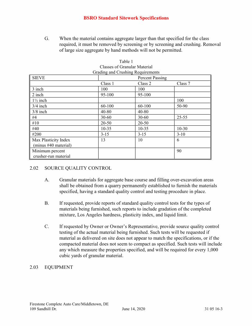
G. When the material contains aggregate larger than that specified for the class
required, it must be removed by screening or by screening and crushing. Removal
of large size aggregate by hand methods will not be permitted.
Table 1
Classes of Granular Material
Grading and Crushing Requirements
SIEVE Percent Passing
Class 1 Class 2 Class 7
3 inch 100 100
2 inch 95-100 95-100
1½ inch 100
3/4 inch 60-100 60-100 50-90
3/8 inch 40-80 40-80
#4 30-60 30-60 25-55
#10 20-50 20-50
#40 10-35 10-35 10-30
#200 3-15 3-15 3-10
Max Plasticity Index
(minus #40 material)
13 10 6
Minimum percent
crusher-run material
90
2.02 SOURCE QUALITY CONTROL
A. Granular materials for aggregate base course and filling over-excavation areas
shall be obtained from a quarry permanently established to furnish the materials
specified, having a standard quality control and testing procedure in place.
B. If requested, provide reports of standard quality control tests for the types of
materials being furnished, such reports to include gradation of the completed
mixture, Los Angeles hardness, plasticity index, and liquid limit.
C. If requested by Owner or Owner’s Representative, provide source quality control
testing of the actual material being furnished. Such tests will be requested if
material as delivered on site does not appear to match the specifications, or if the
compacted material does not seem to compact as specified. Such tests will include
any which measure the properties specified, and will be required for every 1,000
cubic yards of granular material.
2.03 EQUIPMENT
BSRO Standard Sitework Specifications
Firestone Complete Auto Care/Middletown, DE
109 Sandhill Dr. June 14, 2020 31 05 16-4
A. Off-site materials shall be transported to project using well maintained and
operating vehicles. Once on site, transporting vehicles shall stay on designated
haul roads and shall at no time endanger any improvements by rutting,
overloading, or pumping.
2.04 EQUIPMENT
A. Off-site materials shall be transported to project using well maintained and
operating vehicles. Once on site, transporting vehicles shall stay on designated
haul roads and shall at no time endanger any improvements by rutting,
overloading, or pumping.
PART 3 EXECUTION
3.01 STOCKPILING
A. Stockpile on-site at locations indicated by the Owner or Owner’s Representative
in such manner that there will be no standing water or mixing with other
materials.
3.02 BORROW SITES
A. Upon completion of borrow operations, clean up borrow areas as indicated on the
Drawings in a neat and reasonable manner to the satisfaction of the property
owner of the borrow area.
END OF SECTION 31 05 16

BSRO Standard Sitework Specifications
Firestone Complete Auto Care/Middletown, DE
109 Sandhill Dr. June 14, 2020 31 23 01-1
SECTION 31 23 01
EXCAVATION, BACKFILL, AND COMPACTION FOR STRUCTURES
PART 1 GENERAL
1.01 SECTION INCLUDES
A. Excavation to lines, grades, and configuration as shown on Drawings for proposed
structures.
B. Fill to lines, grades, and configuration as shown on Drawings for proposed
structures.
C. Compacting of materials in acceptable manner as specified.
1.02 RELATED SECTIONS
A. Section 31 00 20 – Earthwork
B. Section 31 05 16 – Aggregate Material
C. Geotechnical Report (if available) for boring locations and findings of subsurface
materials and conditions
D. State Department of Transportation standard specifications for highway
construction, latest edition – section concerning Structures.
E. Drawings
1.03 REFERENCE STANDARDS
A. See Section 31 00 20 for a listing of reference standards.
1.04 QUALITY ASSURANCE
A. An independent testing laboratory, selected by Owner and paid by Owner, shall be
retained to perform construction testing on filling operations and subgrade
analysis as specified in Section 31 00 20 and as specified within this section.
1.05 SUBMITTALS
A. Shop drawings or details pertaining to excavating and filling for structures are not
required unless otherwise shown on Drawings or if procedures contrary to
Contract Documents are proposed.
B. If requested by Owner or Owner’s Representative, submit 100 lb. sample of each
type of off-site fill material that is to be used in backfilling in air-tight containers
BSRO Standard Sitework Specifications
Firestone Complete Auto Care/Middletown, DE
109 Sandhill Dr. June 14, 2020 31 23 01-2
to the independent testing laboratory for testing or submit gradation and
certification of aggregate material that is to be used in backfilling to the
independent testing laboratory for review and approval.
PART 2 PRODUCTS
2.01 MATERIALS
A. Fill material from on-site as specified in Section 31 00 20.
B. Fill material from off-site as specified in Section 31 00 20.
C. Aggregate material as specified in Section 31 05 16.
2.02 EQUIPMENT
A. Off-site materials shall be transported to project using well maintained and
operating vehicles. Once on site, transporting vehicles shall stay on designated
haul roads and shall at no time endanger improvements by rutting, overloading, or
pumping.
PART 3 EXECUTION
3.01 PREPARATION
A. Establish lines, elevations, and grades necessary to construct structure subgrades
as shown on Drawings.
B. Protect benchmarks, property corners, and other survey monuments from damage
or displacement. If marker needs to be removed it shall be referenced by licensed
land surveyor and replaced, as necessary, by same.
C. Locate and identify utilities that have previously been installed and protect from
damage.
D. Locate and identify existing utilities that are to remain and protect from damage.
E. Over-excavate and properly prepare areas of subgrade that are not capable of
supporting proposed structures. These areas shall be backfilled with an engineered
fill.
3.02 EXCAVATION AND BACKFILLING
A. Excavate structure foundation areas to lines and grades as shown on Drawings
being careful not to over-excavate beyond elevations needed for structure footings
BSRO Standard Sitework Specifications
Firestone Complete Auto Care/Middletown, DE
109 Sandhill Dr. June 14, 2020 31 23 01-3
unless required to obtain proper compaction. Excavation and backfilling for
structures shall comply with State highway specifications concerning excavation
and backfilling for structures.
B. Place suitable material into project fill areas as specified in Section 31 00 20.
C. Dispose of unsuitable excavated material in a manner and location that is
acceptable to local governing authorities.
D. Perform excavation using capable, well maintained equipment and methods
acceptable to Owner or Owner’s Representative and local governing authorities.
3.03 COMPACTION
A. Maintain optimum moisture content as specified to attain required compaction
density.
B. Materials shall be tested in accordance with Section 31 00 20.
C. If compaction requirements are not complied with at any time during construction
process, remove and re-compact deficient areas until proper compaction is
obtained at no additional expense to Owner.
3.04 MAINTENANCE OF SUBGRADE
A. Finished subgrades shall be verified to ensure proper horizontal and vertical
controls have been complied with and compacted conditions are satisfactory for
construction above subgrade.
B. Use any methods necessary to protect the compacted subgrade from erosion,
excessive moisture or drying, and wheel loading damage during construction from
concrete trucks, dump trucks, and other construction equipment.
C. Remove areas of finished subgrade found to have insufficient compaction density
to depth necessary and replace in manner that will comply with compaction
requirements by use of materials equal to or better than best subgrade material on
site. Surface of subgrade after compaction shall be hard, uniform, smooth, stable,
and true to grade and cross-section.
3.05 FINISH GRADING
A. Finish grading shall be in accordance with Section 31 00 20 and as specified
elsewhere.

BSRO Standard Sitework Specifications
Firestone Complete Auto Care/Middletown, DE
109 Sandhill Dr. June 14, 2020 31 23 01-4
END OF SECTION 31 23 01
BSRO Standard Sitework Specifications
Firestone Complete Auto Care/Middletown, DE
109 Sandhill Dr. June 14, 2020 31 23 02-1
SECTION 31 23 02
EXCAVATION, BACKFILL, AND COMPACTION FOR UTILITIES
PART 1 GENERAL
1.01 SECTION INCLUDES
A. Excavation of trenches for installation of utilities.
B. Backfilling trenches with bedding material as specified and filling trenches with
suitable material to proposed subgrade.
C. Compacting backfill materials in acceptable manner.
D. Local Municipal Utilities and Franchise Utility specifications will govern unless
otherwise noted.
1.02 RELATED SECTIONS
A. Section 02 41 00 – Demolition
B. Section 31 00 20 – Earthwork
C. Section 31 05 16 – Aggregate Materials
D. Section 33 11 00 – Water Distribution Systems
E. Section 33 31 00 – Sanitary Sewer Systems
F. Section 33 41 00 – Storm Sewer Systems
G. Geotechnical Report (if available) for boring locations and findings of subsurface
materials and conditions
H. Construction Drawings
1.03 REFERENCE STANDARDS
A. ASTM D 2321 Underground Installation of Thermoplastic Pipe for Sewers
and Other Gravity-Flow Applications
B. AASHTO T 180 Moisture-Density Relations of Soils Using a 10 lb (4.54 kg)
Rammer and an 18 inch (457 mm) Drop
C. NFPA Chapter 70 National Electric Code
D. AWWA C600 Installation of water lines and appurtenances
1.04 QUALITY ASSURANCE

BSRO Standard Sitework Specifications
Firestone Complete Auto Care/Middletown, DE
109 Sandhill Dr. June 14, 2020 31 23 02-2
A. An independent testing laboratory selected by Owner or Owner’s Representative
and paid by Owner shall perform testing at intervals recommended by Owner or
Owner’s Representative. Compact backfill as specified within this section and in
accordance with the Drawings and Section 31 00 20.
1.05 SUBMITTALS
A. Shop drawings or details pertaining to excavation and filling of utilities are not
required unless required by regulatory authorities or unless use of materials,
methods, equipment, or procedures that are contrary to Construction Drawings or
Specifications are proposed. Do not perform work until required shop drawings
have been accepted by the Owner or Owner’s Representative.
B. Contact utility companies and determine if additional easements will be required
to complete project. Provide written confirmation of status of easements to Owner
or Ownwer’s Representative prior to installation of utilities.
C. If requested by Owner or Owner’s Representative, submit 100 pound sample of
each type of off-site fill material that is to be used in backfilling in air-tight
containers to the independent testing laboratory for testing or submit gradation
and certification of aggregate material that is to be used in backfilling to the
independent testing laboratory for review and recommended approval.
1.06 PROJECT RECORD DOCUMENTS
A. Accurately record actual locations of subsurface utilities, structures, and
obstructions encountered or installed.
PART 2 PRODUCTS
2.01 MATERIALS
A. Bedding Material: Provide Class I-A or I-B granular material per construction
drawings, and in accordance with ASTM D 2321, which is free from clay lumps,
organic, or other deleterious material.
B. Haunching Material: Provide Class I-A, I-B or Class II granular material per
Construction Drawings, and in accordance with ASTM D 2321, which is free
from clay lumps, organic, or other deleterious material. Haunching is considered
the zone from the bottom of the pipe to the spring line of the pipe.
C. Initial Backfill Material: Provide Class I-A, I-B or Class II granular material per
Construction Drawings, and in accordance with ASTM D 2321, which is free
from clay lumps, organic, or other deleterious material. Initial backfill is

BSRO Standard Sitework Specifications
Firestone Complete Auto Care/Middletown, DE
109 Sandhill Dr. June 14, 2020 31 23 02-3
considered the zone from the spring line of the pipe to 6 inches above the top of
the pipe.
D. Backfill material from the site shall be as specified in Section 31 00 20.
E. Backfill material from off-site shall be as specified in Section 31 00 20.
2.02 EQUIPMENT
A. Off-site materials shall be transported to project using well maintained and
operating vehicles. Once on site, transporting vehicles shall stay on designated
haul roads and shall at no time endanger improvements by rutting, overloading, or
pumping.
PART 3 EXECUTION
3.01 PREPARATION
A. Establish lines, elevations, and grades for proposed utility systems.
B. Protect benchmarks, property corners, and other survey monuments from damage
or displacement. If marker needs to be removed it shall be referenced by licensed
land surveyor and replaced, as necessary, by same.
C. Maintain in operating condition all existing utilities, previously installed utilities,
and drainage systems encountered during utility installation. Repair or replace
surface or subsurface improvements concurrently with utility installation.
D. Verify location, size, elevation, and other pertinent data required to make
connections to existing utilities and drainage systems as indicated on Construction
Drawings.
E. Over-excavate and properly prepare areas of subgrade that are not capable of
supporting proposed systems. These areas shall be stabilized by using acceptable
structural fill or additional bedding material placed and compacted as specified in
Section 31 00 20.
F. Install dewatering systems that will be required to construct proposed utilities in
manner that is specified herein.
3.02 EXCAVATION
A. Local utility companies shall be contacted before excavation begins. Dig trench at
proper width and depth for laying pipe, conduit, or cable. Cut trench banks
vertical, if possible, and remove stones from bottom of trench as necessary to
BSRO Standard Sitework Specifications
Firestone Complete Auto Care/Middletown, DE
109 Sandhill Dr. June 14, 2020 31 23 02-4
avoid point-bearing. Over-excavate wet or unstable soil, if encountered, from
trench bottom as necessary to provide suitable base for continuous and uniform
bedding.
B. Trench excavation side walls greater than 5 feet deep shall be sloped, shored,
sheeted, braced, or otherwise supported by means of sufficient strength to protect
workmen in accordance with applicable rules and regulations established for
construction by Department of Labor, Occupational Safety and Health
Administration (OSHA), and by local ordinances. Lateral travel distance to exit
ladder or steps shall not be greater than 25 feet in trenches 4 feet deep or deeper.
C. Perform excavation as indicated on Drawings for specified depths. During
excavation, stockpile materials suitable for backfilling in orderly manner far
enough from bank of trench to avoid overloading, slides, or cave-ins.
D. Remove excavated materials not required or not suitable for backfill or
embankments and waste as specified in Section 31 00 20. Structures discovered
during excavation shall be disposed of as specified in Section 02 41 00.
E. Prevent surface water from flowing into trenches or other excavations by
temporary grading or other methods, as required. Remove accumulated water in
trenches or other excavations by pumping or other acceptable methods.
F. Open cut excavation with trenching machine or backhoe. Where machines other
than ladder or wheel-type trenching machines are used, do not use clods for
backfill. Dispose of unsuitable material and provide other suitable material at no
additional cost to Owner.
G. Accurately grade trench bottom to provide uniform bearing and support for each
section of pipe on bedding material at every point along entire length, except
where necessary to excavate for bell holes and proper sealing of pipe joints, or
other required connections. Dig bell holes and depressions for joints after trench
bottom has been graded. Dig no deeper, longer, or wider than needed to make
joint connection properly.
H. Trench width on each side and below top of pipe shall not be less than 12 inches
or more than 18 inches wider than outside surface of pipe or conduit that is to be
installed to designated elevations and grades. Other trench width for pipe, conduit,
or cable shall be the least practical width that will allow for proper cover and
compaction of trench backfill.
I. Trench depth requirements measured from finished grade or paved surface shall
meet the following requirements or applicable codes and ordinances, whichever is
more stringent:
1. Water Mains: 36 inches to top of pipe barrel or 6 inches below frost line,
established by local building official, whichever is deeper.

BSRO Standard Sitework Specifications
Firestone Complete Auto Care/Middletown, DE
109 Sandhill Dr. June 14, 2020 31 23 02-5
2. Sanitary Sewer: Elevations and grades as indicated on the Drawings.
3. Storm Sewer: Elevations and grades as indicated on the Drawings.
3.03 PIPE BEDDING
A. Accurately cut trenches for pipe or conduit that is to be installed to designated
elevations, 4 inches below bottom of pipe and to width as specified herein. Place a
minimum of 4 inches of bedding material, compact in bottom of trench, and
accurately shape to conform to lower portion of pipe barrel.
3.04 BACKFILLING
A. Criteria: Do not backfill trenches until required tests are performed and utility
systems comply with and are accepted by applicable to governing authorities.
Backfill trenches as specified herein. If improperly backfilled, reopen to depth
required to obtain proper compaction. Backfill and compact, as specified herein,
to properly correct condition in acceptable manner.
B. Backfilling: After pipe or conduit has been installed, bedded, and tested as
required, backfill trench or structure excavation with specified material placed as
shown on Construction Drawings and in accordance with Section 31 00 20.
C. Backfill trenches to contours and elevations shown on the Drawings with
acceptable materials.
D. Systematically backfill to allow maximum time for natural settlement. Do not
backfill over porous, wet, frozen, or spongy subgrade surfaces.
3.05 COMPACTION
A. Exercise proper caution when compacting immediately over top of pipes or
conduits. Water jetting or flooding is not permitted as method of compaction.
B. Maintain optimum moisture content of fill materials, as specified in Section 31 00
20, to attain required compaction density.
C. Materials used for backfill shall comply with requirements of ASTM D 2321 and
Section 31 00 20.
END OF SECTION 31 23 02

BSRO Standard Sitework Specifications
Firestone Complete Auto Care/Middletown, DE
109 Sandhill Dr. June 14, 2020 31 23 03-1
SECTION 31 23 03
EXCAVATION, BACKFILL, AND COMPACTION FOR PAVEMENT
PART 1 GENERAL
1.01 SECTION INCLUDES
A. Excavation to lines, grades, and configuration as shown on Construction
Drawings for proposed pavement areas.
B. Fill to lines, grades, and configuration as shown on Construction Drawings for
proposed pavement areas.
C. Compacting of materials in acceptable manner as specified.
D. The site pavement designs shall conform to the latest DELDOT Road and Bridge
Construction Standards and Specifications.
1.02 RELATED SECTIONS
A. Section 31 00 20 – Earthwork
B. Section 31 05 16 – Aggregate Materials
C. Section 31 23 12 – Pavement Subgrade Preparation
D. Section 32 11 24 – Pavement Base Course [Parking Lots]
E. Section 32 12 21 – Asphaltic Cement Paving
F. Section 32 13 13 – Portland Cement Concrete Paving
G. Geotechnical Report (if available) for boring locations and findings of subsurface
materials and conditions (See Appendix A)
H. Construction Drawings
1.03 REFERENCE STANDARDS
A. See Section 31 00 20.
1.04 QUALITY ASSURANCE
A. The independent testing laboratory, selected by Owner or Owner’s Representative
and paid by Owner, shall be retained to perform construction testing on filling
operations and subgrade analysis in accordance with the Construction Drawings
and as specified in Section 31 00 20 and within this section.

BSRO Standard Sitework Specifications
Firestone Complete Auto Care/Middletown, DE
109 Sandhill Dr. June 14, 2020 31 23 03-2
1.05 SUBMITTALS
A. Shop drawings or details pertaining to excavating and filling for pavement are not
required unless otherwise shown on Construction Drawings or if contrary
procedures to Contract Documents are proposed.
B. If required by Owner or Owner’s Representative, submit 100 lb. sample of each
type of off-site fill material that is to be used in backfilling, in air-tight containers,
to the independent testing laboratory for testing, or submit gradation and
certification of aggregate material that is to be used in backfilling to the
independent testing laboratory for review and recommended approval.
PART 2 PRODUCTS
2.01 MATERIALS
A. Fill material from on-site as specified in Section 31 00 20.
B. Fill material from off-site as specified in Section 31 00 20.
C. Aggregate material as specified in Section 31 05 16.
2.02 EQUIPMENT
A. Transport off-site materials to project using well maintained and operating
vehicles. Once on site, transporting vehicles shall stay on designated haul roads
and shall at no time endanger improvements by rutting, overloading, or pumping.
PART 3 EXECUTION
3.01 PREPARATION
A. Establish lines, elevations, and grades necessary to construct pavements, curb,
curb and gutter, bases, sidewalk, and roadways as shown on Construction
Drawings.
B. Protect benchmarks, property corners, and other survey monuments from damage
or displacement. If marker needs to be removed it shall be referenced by licensed
land surveyor and replaced, as necessary, by same.
C. Locate and identify site utilities that have previously been installed and protect
from damage.
D. Locate and identify existing utilities that are to remain and protect from damage.

BSRO Standard Sitework Specifications
Firestone Complete Auto Care/Middletown, DE
109 Sandhill Dr. June 14, 2020 31 23 03-3
E. Over-excavate and properly prepare areas of subgrade that are not capable of
supporting proposed systems. These areas shall be stabilized by using acceptable
structural fill or aggregate material placed and compacted as specified in Section
31 00 20.
3.02 EXCAVATION
A. Excavate roadway and pavement areas to line and grade as shown on Construction
Drawings.
B. Place suitable material into project fill areas as specified in Section 31 00 20.
C. Dispose of unsuitable excavated material in a manner and location that is
acceptable to local governing authorities.
D. Perform excavation using capable, well maintained equipment and methods
acceptable to local governing authorities.
3.03 FILLING AND SUBGRADE PREPARATION
A. Areas exposed by excavation or stripping shall have a minimum 10 inch thick
layer of select fill placed and compacted. After which, all area where subgrade
preparations for paving are to be performed shall be scarified to minimum depth
of 9 inches and compacted to a minimum of 95 percent of optimum density, in
accordance with ASTM D 698 (or 95 percent of optimum density, in accordance
with ASTM D 1557) at a moisture content of not less than 1 percent below and
not more than 3 percent above optimum moisture content. These areas shall then
be proof-rolled to detect areas of insufficient compaction. Proof-rolling shall be
accomplished by making a minimum of 2 complete passes with fully-loaded
tandem-axle dump truck weighing 25 tons minimum, or approved equal, in each
of 2 perpendicular directions under supervision and direction of the independent
testing laboratory. Areas of failure shall be excavated and recompacted as
specified.
B. Fill materials used in preparation of the subgrade shall be placed in lifts or layers
not to exceed 8 inch loose measure and compacted to a minimum density of 95
percent of optimum density, in accordance with ASTM D 698, (or 95 percent of
optimum density, in accordance with ASTM D 1557) at a moisture content of not
less than 1 percent below and not more than 3 percent above optimum moisture
content.
C. The following table stipulates maximum allowable values for plasticity index (PI)
and liquid limit (LL) of suitable fill materials to be used in specified areas, unless
specifically stated otherwise on Construction Drawings:

BSRO Standard Sitework Specifications
Firestone Complete Auto Care/Middletown, DE
109 Sandhill Dr. June 14, 2020 31 23 03-4
PI LL
*Paving Area, below upper 2 feet 18 45
*Paving Area, upper 2 feet 18 45
*References to depth are to proposed subgrade surface elevations.
3.04 COMPACTION
A. Maintain optimum moisture content as specified to attain required compaction
density.
B. Materials shall be tested in accordance with Section 31 00 20.
C. If compaction requirements are not complied with at any time during construction
process, remove and re-compact deficient areas until proper compaction is
obtained at no additional expense to Owner.
3.05 MAINTENANCE OF SUBGRADE
A. Finished subgrades shall be verified to ensure proper horizontal and vertical
controls have been complied with and compacted conditions are satisfactory for
construction above subgrade.
B. Use any methods necessary to protect the compacted subgrade from erosion,
excessive moisture or drying conditions and wheel loading damage during
construction from concrete trucks, dump trucks, and other construction
equipment.
C. Remove areas of finished subgrade found to have insufficient compaction density
to depth necessary and replace in manner that will comply with compaction
requirements by use of material equal to or better than best subgrade material on
site. Surface of subgrade after compaction shall be hard, uniform, smooth, stable,
and true to grade and cross-section.
3.06 FINISH GRADING
A. Finish grading shall be in accordance with Construction Drawings and as
specified in Section 31 00 20.
B. Check grading of paving areas by string line from grade stakes and/or blue tops
set at not more than 50-foot centers. Tolerances of not more than 0.10-feet, will be
permitted. Contractor shall provide engineering and field staking necessary for
verification of lines, grades, and elevations.

BSRO Standard Sitework Specifications
Firestone Complete Auto Care/Middletown, DE
109 Sandhill Dr. June 14, 2020 31 23 03-5
END OF SECTION 31 23 03
BSRO Standard Sitework Specifications
Firestone Complete Auto Care/Middletown, DE
109 Sandhill Dr. June 14, 2020 31 23 09-1
SECTION 31 23 09
ROCK REMOVAL
PART 1 GENERAL
1.01 SECTION INCLUDES
A. Removal of identified and discovered rock during excavation.
B. Use of explosives to assist rock removal.
C. Incorporating removed rock into fills and embankments.
1.02 RELATED SECTIONS
A. Section 31 00 20 – Earthwork
B. Section 31 23 01 – Excavation, Backfill, and Compaction for Structures
C. Section 31 23 02 – Excavation, Backfill, and Compaction for Utilities
D. Section 31 23 03 – Excavation, Backfill, and Compaction for Pavement
E. Geotechnical Report (if available) for boring locations and findings of subsurface
materials and conditions.
F. Construction Drawings
1.03 REFERENCE STANDARDS
A. National Fire Protection Association (NFPA) latest edition
495 Code For Explosive Materials
1.04 ENVIRONMENTAL REQUIREMENTS
A. Determine environmental effects associated with proposed work and safeguard
those concerns as regulated by law and local governing authorities by reasonable
and practical methods.
1.05 PROJECT CONDITIONS
A. Discrepancy between Drawings and Specifications regarding amount and type of
rock to be removed shall immediately be brought to attention of Owner or
Owner’s Representative. Revised removal plan and schedule shall subsequently
be provided and followed.
1.06 QUALIFICATIONS
A. Submit records of documented experience to Owner or Owner’s Representative
prior to removal of rock by blasting.

BSRO Standard Sitework Specifications
Firestone Complete Auto Care/Middletown, DE
109 Sandhill Dr. June 14, 2020 31 23 09-2
PART 2 PRODUCTS
2.01 MATERIALS
A. Explosives, detonator/delay device, blast mat materials and accessories shall be as
recommended by explosive supplier and shall comply with requirements of
applicable governing authorities.
PART 3 EXECUTION
3.01 PREPARATION
A. Verify site conditions and note subsurface conditions affecting work of this
section.
B. Establish required lines, grades, and elevations that will determine extent of
proposed rock removals.
3.02 ROCK EXCAVATION
A. Rock excavation is defined as igneous, metamorphic, or sedimentary rock that
cannot excavated with a Caterpillar Model No. 320L track-type hydraulic
excavator, equipped with a 42-inch wide short-tip radius rock bucket, rated at not
less than 120 hp flywheel power with a maximum drawbar pull force of not less
than 39,700 lbs. Boulders or masses of rock exceeding one-half cubic yard in
volume hsall also be considered rock excavation. This classification does not
include materials such as loose rock, concrete, or other materials that can can be
removed by means other than drilling and blasting, hoe-ramming, or rock
trenching, but which for reasons of economy in excavating, the contractor chooses
to remove by drilling and blasting, hoe-ramming, or rock trenching techniques.
Cut rock to form level bearing at bottom of footing and trench excavations. In
utility trenches excavate rock to 6 inches below invert elevation of pipe. Remove
shale layers to provide sound and unshattered base for footings or foundations.
Reuse excavated materials on site in accordance with Section 31 00 20.
B. Comply with laws, rules, and regulations (Federal, State, and local authorities and
insurer) which govern storage, use, manufacture, sale, handling, transportation,
licensing, or other disposition of explosives. Take special precautions for proper
use of explosives to prevent harm to human life and damage to surface structures,
utility lines, or other subsurface structures. Do not conduct blasting operations
until persons in vicinity have had ample notice and have reached positions of
safety.
BSRO Standard Sitework Specifications
Firestone Complete Auto Care/Middletown, DE
109 Sandhill Dr. June 14, 2020 31 23 09-3
C. Contractor shall save harmless Owner or Owner’s Representative, Architect, and
Engineer from claims growing out of use of such explosives. Removal of
materials of any nature by blasting shall be done in such manner and at such time
as to avoid damage affecting integrity of design and to avoid damage to new or
existing structures included in or adjacent to work. It shall be Contractor's
responsibility to determine method of operation to ensure desired results and
integrity of completed work.
D. Perform rock excavation in manner that will produce material of such size as to
permit it being placed in embankments in accordance with Section 31 00 20.
Remove rock to limits as indicated on the Drawings. Remove loose or shattered
rock, overhanging ledges and boulders which might dislodge.
E. Use lean concrete or other acceptable materials to replace rock over-blast or over-
excavation in building area to facilitate placement of utilities and future footings.
END OF SECTION 31 23 09
BSRO Standard Sitework Specifications
Firestone Complete Auto Care/Middletown, DE
109 Sandhill Dr. June 14, 2020 31 23 12-1
SECTION 31 23 12
PAVEMENT SUBGRADE PREPARATION
PART 1 GENERAL
1.01 SECTION INCLUDES
A. Preparing the subgrade of areas to be paved with either asphalt or concrete paving
layers.
B. Furnishing and installing granular material to fill over-excavations or to replace
removed unsuitable material.
C. The site pavement designs shall conform to the latest DELDOT Road and Bridge
Construction Standards and Specifications.
1.02 RELATED SECTIONS
A. Site preparation is covered under Section 31 00 10.
B. Excavation and embankment are specified in Section 31 00 20.
C. Aggregate base course is specified in Section 32 11 24.
D. Asphaltic concrete paving is specified in Section 32 12 16.
E. Portland cement concrete paving is specified in Section 32 13 13.
1.03 REFERENCES
A. State Department of Transportation standard specifications for highway construction,
as appropriate, latest edition.
B. AASHTO
1. T 96, "Resistance to Abrasion of Small Size Coarse Aggregate by Us of the Los
Angeles Machine".
2. T 99, "The Moisture-Density Relations of Soils Using a 5.5-lb Rammer and a
12-in. Drop".
3. T 180, "The Moisture-Density Relations of Soils Using a 10-lb Rammer and an
18-in. Drop".
4. T 224, "Correction for Coarse Particles in the Soil Compaction Test".
5. T 238, "Density of Soil and Soil-Aggregate In-Place by Nuclear Methods".
BSRO Standard Sitework Specifications
Firestone Complete Auto Care/Middletown, DE
109 Sandhill Dr. June 14, 2020 31 23 12-2
1.04 SUBMITTALS
A. Submit data concerning source and quality of granular materials being furnished.
Indicate frequency of quality control testing by the source supplier.
1.05 QUALITY ASSURANCE
A. Work under this section shall be accomplished by workers skilled and experienced in
this kind of work, using equipment designed for this kind of work. Maintain
equipment in good operating condition.
1.06 DELIVERY, STORAGE, AND HANDLING
A. Granular material shall be delivered in trucks from the source and directly placed in
the location required for construction, with no intermediate storage or stockpiling
required, as far as practical.
B. Delivery of materials to be paid for by weight or volume measured in haul trucks shall
include a truck ticket delivered to Owner or Owner’s Representative.
PART 2 PRODUCTS
2.01 MATERIALS
A. Refer to Section 31 00 20 for roadbed materials.
B. Refer to Section 31 05 16 for granular materials to fill over-excavations.
PART 3 EXECUTION
3.01 EXAMINATION
A. Examine prior grading or excavation and embankment work for accuracy and
adequacy of construction prior to starting subgrade construction.
3.02 SUBGRADE CONSTRUCTION
A. Prepare subgrade in such a manner as to ensure that the base course, surface course, or
pavement will be placed on a firm foundation that is stable and reasonably free from
dust pockets, wheel ruts, or other defects.
B. Scarify subgrade area to such depth as is necessary for shaping. Shape and compact to
the required grade and section.

BSRO Standard Sitework Specifications
Firestone Complete Auto Care/Middletown, DE
109 Sandhill Dr. June 14, 2020 31 23 12-3
C. Unless a different compaction requirement is indicated on the Drawings, compact the
top 8 inches of subgrade to a density of not less than 95 percent of maximum density
at optimum moisture content obtained by AASHTO T 99, with correction for particles
retained on the #4 sieve not to exceed 30 percent when measured in accordance with
AASHTO T 224. If subgrade material contains more than 30 percent by weight
retained on the #4 sieve, compact to not less than 95 percent of the maximum density
at optimum moisture content obtained by AASHTO T 180.
D. Accomplish compaction by any satisfactory methods that will obtain the required
density.
E. Adjust moisture content by the addition of water or by manipulation and aeration as
necessary under conditions encountered.
F. Compaction operations may be omitted when an old stone or gravel roadbed is used as
a foundation or subgrade for a base course or pavement where scarifying for shaping is
unnecessary and its stability is approved by Owner or Owner’s Representative.
G. Remove soft and yielding materials and other portions of the subgrade that will not
compact readily when rolled or tamped. Fill holes or depressions made by this removal
with approved material. Bring the entire subgrade to the lines, grade, and cross
sections indicated on the Drawings. Compact to specified density.
H. If the succeeding course is not placed immediately after subgrade has been prepared
and subgrade becomes cut up, rough, or unstable, re-shape and re-compact subgrade as
previously specified.
I. Proof-roll subgrade prepared for road, curb and gutter, and sidewalks, prior to
placement of base course or concrete. Proof-rolling vehicle shall be either a roller or
loaded truck or scraper of sufficient weight to identify soft and yielding portions of
compacted surface. Proof-rolling pattern shall be approved by Owner or Owner’s
Representative, and shall generally include passes in two transverse directions.
J. If required by Owner or Owner’s Representative, check lines and grades of subgrade
by a straight edge or mechanical device to demonstrate that the subgrade is constructed
to the lines and grades required by the Drawings, within allowable tolerances.
3.03 DIFFERING ADJACENT PAVEMENT SECTIONS
A. The Drawings indicate different pavement sections within the parking area, such as
normal duty, medium duty, and heavy duty, or similar designations. These differing
sections will be adjacent to each other. Since the different pavement sections will have
different thicknesses of pavement and base course, yet will have a common surface
elevation where the different sections adjoin, the difference must be made up in the
subgrade lines and grades.

BSRO Standard Sitework Specifications
Firestone Complete Auto Care/Middletown, DE
109 Sandhill Dr. June 14, 2020 31 23 12-4
B. Prepare a plan sequence for subgrade preparation that takes into account logical
construction of the different pavement sections. The proposed sequence of
construction shall take into account the need to proof-roll subgrade. Submit plan to
Owner or Owner’s Representative for approval.
C. Construction requirements given in Paragraph 3.02 apply to the subgrade under all
types of pavement. Scarification depth shall be measured from the top of each
subgrade elevation.
D. Differing adjacent subgrade elevations shall be provided with a clean and sound edge.
Measure the elevation difference to assure that correct lines and grades have been
achieved.
E. Any material sloughed from the higher surface onto the lower shall be removed prior
to placement of base course. Sloughed edges may be filled with aggregate base course
material and do not have to be repaired with subgrade material.
3.04 FIELD QUALITY CONTROL
A. A testing laboratory shall be employed, as described in Division 01 of the Project
Manual, to test the density of the base course in place and for thickness, at intervals
determined by Owner or Owner’s Representative. Density testing will be by AASHTO
T 191 or T 238. Correct any deficiencies by scarifying, placing additional material,
mixing, reshaping and re-compacting as necessary to obtain the specified density and
the required lines, grades, and cross sections.
END OF SECTION 31 23 12

BSRO Standard Sitework Specifications
Firestone Complete Auto Care/Middletown, DE
109 Sandhill Dr. June 14, 2020 31 25 01-1
SECTION 31 25 01
GENERAL REQUIREMENTS FOR EROSION AND SEDIMENT CONTROL
PART 1 GENERAL
1.01 SECTION INCLUDES
A. General requirements for temporary erosion and sediment control systems while land-
disturbing activities are occurring during construction.
B. Compliance requirements for Permit: NPDES Generic Permit For Stormwater
Discharge from Large and Small Construction Activities (hereinafter called “the
Permit”.
1.02 RELATED SECTIONS
A. Section 31 25 63 – Silt Fencing
B. Section 31 25 70 – Stabilized Construction Entrance
C. Section 31 25 91 – Concrete Washout
D. Section 32 90 00 – Landscaping
1.03 REFERENCE DOCUMENTS
A. NPDES Generic Permit For Stormwater Discharge from Large and Small Construction
Activities
B. Stormwater Pollution Prevention Plan (SWPPP)
1.04 REGULATORY REQUIREMENTS
A. Discharge of stormwater from the construction site is regulated by Federal and State
laws and regulations. The purpose of these is to minimize discharge of stormwater
pollutants from construction activity and construction support activities.
B. Federal regulations are administered through a state-run permit system in most states,
with Federal permits in only a few states. The Permit is the regulatory document
governing stormwater discharges for this project. The Permit requires that the operator
ensure that the stormwater controls implemented at the site are consistent with all
applicable Federal, State, and local requirements.
C. The permit also prohibits discharge of most non-stormwater discharges, including:
concrete washout water; excavation dewatering water; vehicle washing water; solvents
or lubricating fluids; other fluids.
BSRO Standard Sitework Specifications
Firestone Complete Auto Care/Middletown, DE
109 Sandhill Dr. June 14, 2020 31 25 01-2
D. For the purposes of this project, BSRO is the Operator.
1.05 PROJECT CONDITIONS
A. This project should disturb less than 5 acres; however, it could be considered as part of
a larger, common development. Therefore coverage under the Permit is required.
B. The Site and drainage areas immediately downstream do not include any known
endangered species. The downstream waterway is not subject to TMDL limits, nor is it
on the list of impaired waterways.
1.06 QUALITY ASSURANCE
A. Erosion and sediment control devices (also called best management practices, or
BMPs) shall be installed by workers having training in the purpose of the devices.
Foremen or site superintendents shall have similar training.
1.07 PERMIT PENALTIES
A. Responsibility for payment of any penalties by Federal, State, or local authorities
based on violations of the Permit or related laws is as follows.
1. Penalties assessed because of defects in the selection or design of BMPs shall be
paid by Owner.
2. Penalties assessed because of ineffective installation of BMPs shall be paid by
Contractor.
3. Penalties assessed because of ineffective or insufficient maintenance of BMPs
shall be paid by Contractor.
4. Penalties assessed due to failure to conduct inspections when required and to
document those inspections shall be paid by Owner.
5. Penalties assessed for inadequate storage or display of records or documents
related to the Permit shall be paid by Contractor.
6. Penalties assessed for failure to update the SWPPP as required shall be paid by
Owner.
B. Owner shall deduct the amount of penalties due from Contractor from monies owed to
Contractor. Owner or Owner’s Representative shall prepare a Change Order to reflect
this deduction.
C. Where a penalty payable by Contractor is anticipated, but has not yet been assessed by
a regulatory agency, and where that penalty may not be assessed for a period of
months, Contractor may provide a financial assurance to Owner in lieu of having
money withheld. Financial assurance may be a surety bond for the specific purpose, or
an irrevocable letter of credit. The term shall be a minimum of two years, and the
amount shall be the probably maximum amount of the fine.
BSRO Standard Sitework Specifications
Firestone Complete Auto Care/Middletown, DE
109 Sandhill Dr. June 14, 2020 31 25 01-3
PART 2 PRODUCTS
2.01 POSTING AND RECORD STORAGE
A. Posting and record storage facilities are required for this project. Provide a suitable
bulliten board and storage “mailbox”-type unit for this purpose. Location and details
of construction may be shown on the Drawings. If they are not, use construction
techniques customary in the area of the project. This shall include a rain gauge.
PART 3 EXECUTION
3.01 INSTALLATION
A. Install erosion and sediment control devices where indicated on and according to the
details on the Drawings and requirements given in individual specification sections.
Location of posting and record storage center, if required, shall be where indicated on
the Drawings; or, if not indicated, in a place that is visible to the site entrance where
the public and regulatory inspectors can easily see it from a public right-of-way.
B. Installation shall be approved by Owner or Owner’s Representative prior to the start of
land-disturbing activities. Make any changes required until erosion and sediment
control devices are approved by Owner or Owner’s Representative.
C. Deficiencies in or changes required to Drawings as applied to current conditions will
be brought to the attention of Owner or Owner’s Representative for remedial action.
D. Owner or Owner’s Representative has authority to limit surface area of erodible earth
material exposed by clearing and grubbing, excavation, borrow, and embankment
operations and to direct Contractor to provide immediate additional erosion and
sediment control measures. Additional material and work required and authorized by
Owner or Owner’s Representative which is beyond extent of Drawings shall be paid
for by Owner. Owner or Owner’s Representative shall prepare a Contract Modification
covering this.
3.02 MAINTENANCE
A. Perform maintenance of erosion and sediment control devices as often as necessary to
keep them in effective working condition. Frequency of maintenance will be
dependent on amount of run-off and amount of sediment build-up.
3.03 REMOVAL
BSRO Standard Sitework Specifications
Firestone Complete Auto Care/Middletown, DE
109 Sandhill Dr. June 14, 2020 31 25 01-4
A. Remove erosion and sediment control devices as soon as upstream site stabilization is
completed, or when no longer needed to minimize erosion or control sediment.
B. Where erosion and sediment control devices are removed, restore areas to
preconstruction conditions. However, regardless of pre-construction condition, areas
shall not be left unstabilized.
3.04 SITE HOUSKEEPING
A. Maintain site in a manner to minimize potential stormwater pollution, including:
1. trash and litter control, and
2. spill prevention activities.
3.05 INSPECTIONS
A. Owner or Owner’s Representative is responsible for conducting inspections required
by the Permit and the SWPPP, and for documenting those inspections in reports.
Owner or Owner’s Representative will provide Contractor copies of those inspection
reports to store on site.
END OF SECTION 31 25 01
BSRO Standard Sitework Specifications
Firestone Complete Auto Care/Middletown, DE
109 Sandhill Dr. June 14, 2020 31 25 63-1
SECTION 31 25 63
SILT FENCE
PART 1 GENERAL
1.01 SECTION INCLUDES
A. Wire-Backed Silt Fence (WBSF)
1.02 RELATED SECTIONS
A. Section 31 25 01 – General Requirements for Erosion and Sediment Controls
1.03 REFERENCES
A. ASTM
D 4439 Terminology for Geosynthetics
D 4491 Test Methods for Water Permeability of Geotextiles by Permittivity
D 4533 Test Method for Trapezoid Tearing Strength of Geotextiles
D 4595 Test Method for Tensile Properties of Geotextiles by the Wide-Width Strip
Method
D 4632 Test Method for Grab Breaking Load and Elongation of Geotextiles
D 4751 Test Method for Determining Apparent Opening Size of a Geotextile
D 4873 Guide for Identification, Storage, and Handling of Geosynthetic Rolls and
Samples
D 5199 Test Method for Measuring the Nominal Thickness of Geosynthetics
D 5261 Test Method for Measuring Mass per Unit Area of Geotextiles
D 5493 Test Method for Permittivity of Geotextiles Under Load
D 6241 Test Method for the Static Puncture Strength of Geotextiles and Geotextile-
Related Products Using a 50-mm Probe
D 6461 Specification for Silt Fence Materials
D 6462 Practice for Silt Fence Installation
1.04 SUBMITTALS
A. Submit manufacturer’s data, catalogue pages, etc. for geofabrics and for wire backing,
if required. Fabric information should include, as a minimum:
1. Apparent opening size
2. Permittivity
3. Flow Rate (Flux)
BSRO Standard Sitework Specifications
Firestone Complete Auto Care/Middletown, DE
109 Sandhill Dr. June 14, 2020 31 25 63-2
1.05 PROJECT CONDITIONS
A. Silt fencing is required to provide a silt barrier on the site during the term of land
disturbing activities. This is to comply with the Construction General Permit and the
SWPPP.
1.06 QUALITY ASSURANCE
A. Silt fence systems shall be assembled and installed by workers who are experienced in
this type of construction. A foreman or superintendent experienced in installing
erosion and sediment control devices, and particularly silt fencing, shall oversee the
work.
B. Owner or Owner’s Representative shall inspect silt fence installation prior to any earth
disturbing activity from being performed in the area tributary to the silt fence.
1.07 DELIVERY, STORAGE, AND HANDLING
A. Handle all materials in such manner as to preserve their quality and fitness for the
work.
B. Store silt fence components so as to assure preservation of quality and fitness for the
work. Stored materials shall be located so as to facilitate prompt inspection.
C. Any limitations on areas where materials can be stored are given in the General
Requirements or on the Drawings.
PART 2 PRODUCTS
2.01 MATERIALS
A. Standard silt fence fabric shall be one of the following fabrics.
1. Propex, Geotex 2127
2. Thrace-Linq, GTF 170SF
3. Mutual Industries, WF 200
4. Hanes Geo, TerraTex SF-90
B. Silt fence fabric shall include enough UV inhibitors and stabilizers to provide a
minimum of 1 year service life from outdoor exposure.
C. Belted Silt Retention Fence: fabric of spunbond polyester material, reinforced by
internal scrim (or net), as manufactured by Silt-Saver, Inc.
D. Fence posts shall comply with the details indicated on the Drawings.

BSRO Standard Sitework Specifications
Firestone Complete Auto Care/Middletown, DE
109 Sandhill Dr. June 14, 2020 31 25 63-3
E. Wire backing shall be 16 gauge hog-wire type fence fabric, on a 4x4 spacing. Required
width of fabric is indicated on the Drawings.
F. Fence ties shall be aluminum or steel. Plastic ties (zip or otherwise) are not acceptable.
PART 3 EXECUTION
3.01 EXAMINATION
A. Examine silt fence fabric to verify it is undamaged, and that it complies with the
specifications.
B. Examine the area where silt fence is to be installed and verify that any initial clearing
or grubbing has been done to allow for installation.
3.02 PREPARATION
A. Location where silt fence is to be installed shall be marked on the ground prior to
beginning of installation.
B. Remove all debris from the surface that might hinder effective installation.
3.03 INSTALLATION – TRENCHING AND BACKFILL
A. Excavate embedment trench a minimum of 6 inches deep by 6 inches wide, unless
other dimensions are indicated on the Drawings.
1. Place excavated material on the upstream side of the trench
2. Hand clear loose debris from trench.
3. Place fence fabric in trench, flush on bottom and up the downstream side. Lay
part of fabric that is to remain above ground on the ground on downstream side.
Splice fabric when required, overlapping pieces in accordance with fabric
manufacturer’s recommendations, but not less than 6 inches. Do not incorporate
short remnants of fabric into a longer fence run.
4. Arrange fabric so that after it is raised to a vertical position it is not more than 18
inches high.
5. Selvage end of silt fence shall always be placed on the non-buried end.
6. Backfill trench with excavated material. Do not allow any stones or cobbles
larger than 2 inches (in largest dimension) to be used in backfill. Backfill shall
be free of deleterious materials, such as roots, trash, clods, sod, etc.
7. Mound earthen material over the trench at least 2 inches higher than adjacent
ground.
8. Compact trench using mechanical compaction, taking care not to damage
exposed fabric. A loaded wheeled vehicle may be used for compaction if
approved by Owner or Owner’s Representative and if compaction appears
adequate to prevent washout of the trench backfill or piping under trench. A
BSRO Standard Sitework Specifications
Firestone Complete Auto Care/Middletown, DE
109 Sandhill Dr. June 14, 2020 31 25 63-4
minimum of four passes of a vehicle weighing the equivalent of a loaded
tandem-axle dump truck is the minimum compaction effort required. After
compaction, top of backfill should be approximately level with adjacent grade.
9. Where wire mesh backing is used, embed it a minimum of 2 inches into the
trench prior to compaction, on the downstream side of the fabric.
B. Fence Assembly
1. Lift the slack fence fabric, and wire backing when used, from the ground and
either lay on the other side of the ground or hold vertically in place to allow
fence post installation.
2. Install fence posts at the spacing indicated on the Drawings. Posts shall be
driven into undisturbed earth just on the downstream side of the trench, as close
to the fabric as possible without puncturing or damaging fabric. Fence posts that
wobble or otherwise do not seem firmly in place shall be removed and re-
installed a short distance away.
3. Install a fence post at any splice location, and tie fabric to post as specified.
4. If wooden posts that cannot be driven are used, excavate holes with care; avoid
damage to fabric and wire already installed. Annulus of holes must be backfilled
to prevent posts from wobbling.
5. Tie the fabric, and wire backing when used, to fence posts as indicated on the
Drawings.
6. When steel posts are used, nipples shall face away from fabric.
C. Inspect completed fence to verify that:
1. fabric is properly embedded;
2. fabric is properly lapped and spliced when necessary;
3. fabric is free of punctures or other damage;
4. trench is properly backfilled;
5. wire mesh, where used, is properly embedded;
6. posts are properly spaced;
7. fabric (and wire when used) are tied to posts at the required frequency; and
8. no opportunity exists for run-off to go through, under, or around the silt fence.
D. If the fence is in any way found not to comply with these specifications, or to result in
an installation that will not comply with the SWPPP and the NPDES permit, repair or
remove and replace the fence to bring into compliance.
E. The mere laying the lower portion of the fence fabric on the ground and covering it
with a layer of earthen material (i.e. not digging an embedment trench) is not
acceptable.
BSRO Standard Sitework Specifications
Firestone Complete Auto Care/Middletown, DE
109 Sandhill Dr. June 14, 2020 31 25 63-5
3.04 MAINTENANCE
A. Silt fence shall be maintained during the entire project, or for whatever portion of the
project it is required for controlling sediment movement from the site. The SWPPP
and the Drawings indicate required specific sequencing of construction, if any.
B. Maintenance of silt fence includes:
1. Removal of accumulated sediment when it exceeds 1/3 of the fabric height.
2. Repair of damage due to construction activities.
3. Repair of damage due to normal wear and tear.
4. Correction of any defects discovered from inspections during the project, such as
ineffective bedding or improper joints.
C. When silt fencing deteriorates to the point that it no longer functions as an effective
silt barrier, replace with new silt fencing complying with this section.
END OF SECTION 31 25 63

BSRO Standard Sitework Specification
Firestone Complete Auto Care/Middletown, DE
109 Sandhill Dr. June 14, 2020 31 25 70-1
SECTION 31 25 70
STABILIZED CONSTRUCTION ENTRANCE
PART 1 GENERAL
1.01 SECTION INCLUDES
A. Furnishing, installing, maintaining, and removing temporary stabilized
construction entrances.
1.02 RELATED SECTIONS
A. Section 31 25 01 – Erosion and Sediment Control – General Requirements
1.03 QUALITY ASSURANCE
A. See Section 31 25 01.
1.04 SUBMITTALS
A. If a manufactured system will be used, submit manufacturer’s information for that
system.
PART 2 PRODUCTS
2.01 MATERIALS
A. 3 to 6 inch diameter stones, a mixture roughly equivalent to that used by various
State highway departments, often with the name “Stone Backfill”. Shall be free of
shale and excessive fines.
B. Non-woven polypropylene, adequate weight to support stones and traffic loads.
Alternate fabrics may be submitted to Owner or Owner’s Representative for
review and approval.
PART 3 EXECUTION
3.01 INSTALLATION
A. Strip topsoil from area to serve as stabilized construction entrance, and grade as
required.

BSRO Standard Sitework Specification
Firestone Complete Auto Care/Middletown, DE
109 Sandhill Dr. June 14, 2020 31 25 70-2
B. Install filter fabric. Maintain contact between fabric and soil beneath.
C. Install stones according to the details on the Drawings.
3.02 MAINTENANCE
A. When the spaces between the top stones begin to be clogged with sediment,
restore the construction entrance to its intended function by top dressing with
more stones or by mechanically mixing the stones. Washing sediment away from
stones is not a preferred practice, unless the washed sediment is properly
contained and treated.
3.03 REMOVAL
A. When no longer required, remove according to Section 31 25 01.
END OF SECTION 31 25 70
BSRO Standard Sitework Specifications
Firestone Complete Auto Care/Middletown, DE
109 Sandhill Dr. June 14, 2020 31 25 91-1
SECTION 31 25 91
CONCRETE WASHOUT SYSTEMS AND PRACTICES
PART 1 GENERAL
1.01 SECTION INCLUDES
A. Temporary concrete washout station, either pre-fabricated or self-installed.
1.02 RELATED SECTIONS
A. Section 31 25 01 – General Requirements for Erosion and Sediment Control
1.03 REFERENCE DOCUMENTS
A. As listed in Section 31 25 01.
1.04 QUALITY ASSURANCE
A. Provide a site superintendent or foreman who has had education and experience in
the purpose of concrete washout containment.
B. Enforce concrete washout procedures on subcontractors and ready-mix concrete
supplier.
C. The Drawings show a wood frame self-installed washout station. Contractor may
use other types of construction for this washout station, such as earthen berm
(above or below ground) or a pre-fabricated system, so long as the alternate provide
equivalent or better service as the one shown on the Drawings.
PART 2 PRODUCTS
2.01 SELF-INSTALLED SYSTEMS
A. Plastic liner: 6 mil (minimum) thick polyethylene sheeting, free from slits, holes,
or other defects that will prevent it from containing concrete washout water.
B. The Drawings show a wood frame washout station. Other materials, such as wood
frames, frame stakes, alternate wall materials, etc. shall be suitable for the
intended purpose.
2.02 PRE-FABRICATED SYSTEMS
BSRO Standard Sitework Specifications
Firestone Complete Auto Care/Middletown, DE
109 Sandhill Dr. June 14, 2020 31 25 91-2
A. Specially made for concrete washout; undamaged from prior use; leak free;
adequately sized for the washout needs of the project, including rainfall allowance
and freeboard. Hopper material may be metal or plastic.
PART 3 EXECUTION
3.01 SITING
A. The Drawings indicate a location for the concrete washout station. An alternate
location may be proposed. Obtain Owner’s or Owner Representatives’s approval
before changing location. Washout station shall not be within 50 feet of a storm
drain.
B. Locate near a stabilized construction entrance or provide a dedicated stabilized
construction entrance for the washout facility.
C. Either provide signage to the washout facility or provide a person to direct
concrete trucks to the washout area.
3.02 SELF-INSTALLED SYSTEM
A. Size self-installed systems based on anticipated amount of washout water, plus an
allowance for rainfall, plus 4 inches of freeboard. Both above ground and below
ground systems are allowed.
B. Liner shall make continuous contact with soil beneath so as to avoid tears when
washout water is dumped.
3.03 PRE-FABRICATED SYSTEMS
A. Securely anchor against movement from bumping. Install reasonably level to
allow full capacity of hopper to be used.
3.04 OPERATION AND MAINTENANCE
A. Washout practices:
1. Perform washout of concrete trucks offsite or in designated concrete
washout areas only.
2. Do not wash out concrete trucks onto the ground, or into storm drains, open
ditches, streets, or streams.
3. Do not allow excess concrete to be dumped onsite, except in designated
concrete washout areas.
4. Perform washout in a manner that minimizes spray and splatter outside the
containment area.

BSRO Standard Sitework Specifications
Firestone Complete Auto Care/Middletown, DE
109 Sandhill Dr. June 14, 2020 31 25 91-3
B. Remove accumulated concrete solid and liquid waste when necessary to maintain
washout containment capacity for future concrete work. If cleaning damages the
liner of a self-installed system, replace the liner before any more concrete washout
occurs.
3.05 CLEANING
A. Upon completion of concrete work, remove accumulated concrete solid waste and
any residual liquid waste and dispose off-site according to regulations. This
includes removal of visible concrete solids that have fallen near the washout
station, and any contaminated soils.
B. Dismantle self-installed system and remove non-soil materials from site. Remove
pre-fabricates systems from site.
C. Restore washout area in accordance with Section 31 25 01.
END OF SECTION 31 25 91
BSRO Standard Sitework Specifications
Firestone Complete Auto Care/Middletown, DE
109 Sandhill Dr. June 14, 2020 31 31 16-1
SECTION 31 31 16
TERMITE CONTROL
PART 1 GENERAL
1.01 SUMMARY
A. Provide soil treatment for termite control, as herein specified.
1.02 RELATED DOCUMENTS
A. Drawings and general provisions of Contract, including General Conditions,
Supplementary Conditions, and Division 01 Specification sections, apply to work
of this section.
1.03 SUBMITTALS
A. Product Data: Submit manufacturer's technical data and application instructions.
1.04 QUALITY ASSURANCE
A. In addition to requirements of these specifications, comply with manufacturer's
instructions and recommendations for work, including preparation of substrate
and application.
B. Engage a professional pest control operator, licensed in accordance with
regulations of governing authorities for application of soil treatment solution.
C. Use only termiticides which bear a Federal registration number of the U.S.
Environmental Protection Agency.
1.05 JOB CONDITIONS
A. Restrictions: Do not apply soil treatment solution until excavating, filling and
grading operations are completed, except as otherwise required in construction
operations.
B. To ensure penetration, do not apply soil treatment to frozen or excessively wet
soils or during inclement weather. Comply with handling and application
instructions of the soil toxicant manufacturer.
1.06 SPECIFIC PRODUCT WARRANTY
A. Submit under provisions of Section 01 78 00. Furnish written warranty certifying
that applied soil termiticide treatment will prevent infestation of subterranean
BSRO Standard Sitework Specifications
Firestone Complete Auto Care/Middletown, DE
109 Sandhill Dr. June 14, 2020 31 31 16-2
termites and, that if subterranean termite activity is discovered during warranty
period, Contractor will re-treat soil and repair or replace damage caused by
termite infestation.
1. Bid Alternate: At Owner's option, at the termination of the guarantee, an
extension renewal of inspections and service treatment shall be made
available to Owner.
PART 2 PRODUCTS
2.01 SOIL TREATMENT SOLUTION
A. Use an emulsible concentrate termiticide for dilution with water, specially
formulated to prevent infestation by termites. Fuel oil will not be permitted as a
diluent. Provide a solution consisting of one of following chemical elements and
concentrations:
1. Chloropyrifos ("Dursban TC"); 1.0 percent in water emulsion.
2. Permathrin ("Dragnet", "Torpedo"); 0.5 percent in water emulsion.
B. Other solutions may be used as recommended by Applicator if also acceptable to
Owner’s Representative and approved for intended application by jurisdictional
authorities. Use only soil treatment solutions which are not injurious to planting.
PART 3 EXECUTION
3.01 APPLICATION
A. Surface Preparation: Remove foreign matter which could decrease effectiveness
of treatment on areas to be treated. Loosen, rake and level soil to be treated,
except previously compacted areas under slabs and foundations. Toxicants may
be applied before placement of compacted fill under slabs, if recommended by
toxicant manufacturer.
B. Application Rates: Apply soil treatment solution as follows:
C. Under slab-on-grade structures, treat soil before concrete slabs are placed, using
the following rates of application:
1. Apply 4 gallons of chemical solution per 10 linear feet to soil in critical
areas under slab, including entire inside perimeter inside of foundation
walls, along both sides of interior partition walls, around plumbing pipes
and electric conduit penetrating slab, and around interior column footers.
2. Apply 1 gallon of chemical solution per 10 square feet as an overall
treatment under slab and attached slab areas where fill is soil or unwashed
BSRO Standard Sitework Specifications
Firestone Complete Auto Care/Middletown, DE
109 Sandhill Dr. June 14, 2020 31 31 16-3
gravel. Apply 1-1/2 gallons of chemical solution to areas where fill is
washed gravel or other coarse absorbent material.
3. Apply 4 gallons of chemical solution per 10 linear feet of trench, for each
foot of depth from grade to footing, along outside edge of building. Dig a
trench 6 to 8 inches wide along outside of foundation to a depth of not less
than 12 inches. Punch holes to top of footing at not more than 12 inches o.c.
and apply chemical solution. Mix chemical solution with the soil as it is
being replaced in trench.
D. At expansion joints, control joints, and areas where slabs will be penetrated, apply
at rate of 4 gallons per 10 linear feet of penetration.
E. Post signs in areas of application to warn workers that soil termiticide treatment
has been applied. Remove signs when areas are covered by other construction.
F. Reapply soil treatment solution to areas disturbed by subsequent excavation,
landscape grading, or other construction activities following application.
END OF SECTION 31 31 16
BSRO Standard Sitework Specifications
Firestone Complete Auto Care/Middletown, DE
109 Sandhill Dr. June 14, 2020 31 32 13-1
SECTION 31 32 13
SOIL STABILIZATION
PART 1 GENERAL
1.01 SECTION INCLUDES
A. Excavation, treatment, and backfilling of subgrade for lime stabilization.
B. Excavation, treatment, and backfilling of subgrade for cement stabilization.
C. Excavation, treatment, and backfilling of subgrade for fly ash stabilization.
D. Installation of Geotextile Fabric for stabilization of subgrade.
E. The site pavement designs shall conform to the latest DELDOT Road and Bridge
Construction Standards and Specifications.
1.02 RELATED SECTIONS
A. Section 31 00 20 – Earthwork
B. Section 31 05 16 – Aggregate Materials
C. Section 31 23 01 – Excavation, Backfill, and Compaction for Structures
D. Section 31 23 02 – Excavation, Backfill, and Compaction for Utilities
E. Section 31 23 03 – Excavation, Backfill, and Compaction for Pavement
F. Geotechnical Report (if available) for boring locations and findings of subsurface
materials and conditions
G. Construction Drawings
1.03 REFERENCE STANDARDS
A. ASTM International (ASTM) latest edition
C 150 Portland Cement
C 618 Fly Ash and Raw or Calcined Natural Pozzolan for use as a Mineral
Admixture in Portland Cement Concrete
C 977 Quicklime and Hydrated Lime for Soil Stabilization
D 1633 Compressive Strength of Molded Soil-Cement Cylinders
B. American Association of State Highway and Transportation Officials (AASHTO)
latest edition
M 216 Lime for Soil Stabilization
C. National Lime Association (NLA)
Bulletin 326 Lime Stabilization Construction Manual
1.04 ENVIRONMENTAL REQUIREMENTS

BSRO Standard Sitework Specifications
Firestone Complete Auto Care/Middletown, DE
109 Sandhill Dr. June 14, 2020 31 32 13-2
A. Do not install mixed materials in wind in excess of 10 mph or when temperature
is below 40 degrees Fahrenheit.
1.05 QUALITY ASSURANCE
A. Perform work as specified and in accordance with state and local regulations.
1.06 SUBMITTALS
A. If required by Owner or Owner’s Representative, submit 100 lb. sample of each
material to be used at the site in air-tight containers to the independent testing
laboratory for testing or submit gradation and certification of material that is to be
used at the site to the independent testing laboratory for review and recommended
approval.
B. Submit name of each material supplier including the specific type and source of
each material. Change in material source requires an additional submittal to the
Owner or Owner’s Representative for approval.
C. Submit mix design and materials mix ratio that will achieve specified results and
also comply with state and local authorities’ requirements for soil stabilization.
PART 2 PRODUCTS
2.01 MATERIALS
A. Hydrated Lime: Complying with ASTM C 977 and applicable standards of the
State DOT
B. Portland Cement: ASTM C 150; type of Portland cement as used by the State
DOT for soil stabilization
C. Fly Ash: Complying with ASTM C618 and with State DOT practice
D. Subsoil: Re-use existing when acceptable
E. Geotextile Fabric for Stabilization
1. Mirafi 500X or 600X
2. Phillips 66 Supac 6WS
3. DuPont Typar 3401 and 3601
4. Trevira S1114 and S1120
5. Tensar SS-1 and SS-2
6. Exxon GTF-200 or 350
2.02 EQUIPMENT

BSRO Standard Sitework Specifications
Firestone Complete Auto Care/Middletown, DE
109 Sandhill Dr. June 14, 2020 31 32 13-3
A. Perform operations using suitable, well maintained equipment capable of
excavating subsoil, mixing and placing materials, wetting, consolidating, and
compacting material.
PART 3 EXECUTION
3.01 PREPARATION
A. Obtain approval from the independent testing laboratory and approval from the
Owner or Owner’s Representative of recommended mix design before proceeding
with placement.
B. Do not start stabilization without weather and soil conditions being favorable for
successful application of proposed material.
C. Proof-roll to identify areas in need of stabilization.
3.02 EXCAVATION
A. Excavate subsoil to depth sufficient to accommodate soil stabilization.
B. Remove lumped subsoil, boulders, and rock that interfere with achieving uniform
subsoil conditions.
3.03 SOIL TREATMENT AND BACKFILLING
A. Lime Stabilized Subgrade: Where indicated on the Drawings or as determined
necessary by proof-rolling, treat subgrade with hydrated lime in accordance with
applicable state highway department specifications. Compact to not less than 95
percent of optimum density as determined by ASTM D 698 (or 92 percent of
optimum density, in accordance with ASTM D 1557).
B. Cement Stabilized Subgrade: Where indicated or the Drawings, or as determined
necessary by proof-rolling, treat subgrade with Portland cement in accordance
with applicable state highway department specifications. Compact to not less than
95 percent of optimum density as determined by ASTM D 698 (or 92 percent of
optimum density, in accordance with ASTM D 1557).
C. Fly Ash Stabilized Subgrade: Where indicated on the Drawings, or as determined
necessary by proof-rolling, treat subgrade with fly ash in accordance with
applicable state highway department specifications. Compact to not less than 95
percent of optimum density as determined by ASTM D 698 (or 92 percent of
optimum density, in accordance with ASTM D 1557).
BSRO Standard Sitework Specifications
Firestone Complete Auto Care/Middletown, DE
109 Sandhill Dr. June 14, 2020 31 32 13-4
D. Maintain optimum moisture of mix materials to attain required stabilization and
compaction.
E. Finish subgrade surface in accordance with Section 31 00 20.
3.04 GEOTEXTILE FABRIC
A. Place fabric in those areas that are indicated on the Drawings or in those areas
where additional stabilization prior to placement of base course is required.
B. Place fabric specified on the Drawings and in Specifications in accordance with
manufacturer's recommendations.
END OF SECTION 31 32 13
BRSO Standard Sitework Specifications
Firestone Complete Auto Care/Middletown, DE
109 Sandhill Dr. June 14, 2020 31 80 00-1
SECTION 31 80 00
GENERAL REQUIREMENTS FOR SITE RESTORATION
PART 1 GENERAL
1.01 SCOPE
A. This section includes restoration of areas disturbed by this project. "Disturbed by
this project" is defined as the excavation area plus any area in project vicinity
disturbed by Contractor’s operations, including operations of Subcontractors and
suppliers, and utility owner operations necessary to complete this project.
B. Keep work areas as clean and neat as practicable. Lawns, gardens, and vehicle and
pedestrian crossings shall have excess quantities of supplies, excavated material,
man made debris, and organic matter removed from the area immediately
following construction.
C. All property improvements shall be restored in kind or as nearly as practicable as
determined by Owner or Owner’s Representative.
1.02 RELATED WORK
A. Earthwork is specified in Section 31 00 20.
1.03 QUALITY ASSURANCE
A. Adequate equipment and qualified personnel shall be applied to this phase of the
work from the beginning of the project.
PART 2 PRODUCTS
2.01 TOPSOIL
A. Topsoil shall be placed on disturbed areas equal to or better than the material on
each side of the disturbed area.
2.02 FERTILIZER
A. Fertilizer shall be 10-20-10 (nitrogen-phosphorous-potash) delivered to the site in
labeled containers conforming to Arkansas fertilizer laws and bearing the name
and warranty of the producer.

BRSO Standard Sitework Specifications
Firestone Complete Auto Care/Middletown, DE
109 Sandhill Dr. June 14, 2020 31 80 00-2
2.03 SEED
A. Seed mixture per Class of Restoration
1. Class 1 Restoration seed mixture shall be 40 percent Lawn Fescue, 30
percent Rye Grass (annual), and 30 percent Blue Grass.
2. Class 2 Restoration seed mixture shall be 40 percent Field Fescue, 40
percent Rye Grass (annual), and 20 percent White Clover (common).
3. Class 3 Restoration seed mixture shall be 40 percent Tall Fescue (Kentucky
31), 40 percent Rye Grass (annual), and 20 percent White Clover
(common).
B. Seed shall be labeled according to current requirements of the Arkansas State
Plant Board.
C. Seed shall be 95 percent pure and 85 percent germination by weight. 50 noxious
weed seeds shall be the maximum amount allowed per pound. The following
types of seed are not allowed in any amount: Johnson grass, wild onion, wild
garlic, field bindweed, or nut grass.
D. Fescue seed shall be certified endophyte free.
2.04 SOD
A. Sod shall consist of a densely rooted growth of Bermuda grass, Zoysia, etc. and
shall be substantially free from noxious weeds and undesirable grasses. The sod
shall be cut in uniform strips with a minimum of 2 inches of root depth
approximately 12 inches in width and not less than 12 inches in length but not
longer than can be conveniently handled and transported.
B. Sod for replacement of disturbed sodded areas shall be approved by Owner or
Owner’s Representative before cutting.
2.05 MULCH
A. Straw mulch shall be good grade clean straw, free of weeds or seed, and of a
quality approved by Owner or Owner’s Representative prior to use.
2.06 WATER
A. Water shall be of irrigation quality, free of impurities which are detrimental to
plant growth.
PART 3 EXECUTION

BRSO Standard Sitework Specifications
Firestone Complete Auto Care/Middletown, DE
109 Sandhill Dr. June 14, 2020 31 80 00-3
3.01 SURFACE NOT GRAVELED OR PAVED FOR VEHICLE OR PEDESTRIAN USE.
A. Class 1 Restoration – Areas of construction within lawns, gardens, or other well-
kept areas, including street rights-of-way that are kept as lawns by adjacent
landowners.
1. After trench settlement is complete, replace topsoil to same depth as
adjacent undisturbed areas.
2. Trim and remove all damaged limbs on trees, trim limbs of shrubs or, if
necessary, cut damaged shrub just below ground surface.
3. Hand rake disturbed area to remove all rocks 1/2 inch or larger measured in
any direction, all man-made debris, and all organic material. Debris and
excess material shall be disposed of in a manner approved by the Owner or
Owner’s Representative and applicable government regulations.
4. After raked area is accepted by Owner or Owner’s Representative for
seeding,
a. apply 250 pounds of fertilizer per acre.
b. apply 0.15 pounds of seed per 100 square feet.
c. apply 4,000 pounds of mulch per acre.
5. Apply straw mulch using an asphalt mixing blower. Add asphalt to straw in
sufficient quantity to bind mulch together. Top spraying of straw with
asphalt is not acceptable.
6. As an alternate method of seeding, seed may be applied by hydro mulching.
The seed shall be mixed with water and wood cellulose fiber. The wood
cellulose fiber shall be composed of natural wood chips and shall contain no
growth or germination inhibiting factors and shall contain a water soluble,
nontoxic coloring agent.
7. Other alternate methods will be considered by Owner or Owner’s
Representative but shall not be utilized until expressly authorized by Owner
and Owner’s Representative.
8. Where ground cover adjacent to disturbed areas contains grasses such as
Bermuda grass, Zoysia, or other grasses not included in the prescribed seed
mixture, Contractor shall remove and stockpile the existing sod on the job
site. After trench settlement is complete, the sod shall be replaced to a
condition equal to, or better than, that prior to construction. In the event that
insufficient sod has been stored, or sod has been lost or destroyed, the
Contractor shall be responsible for providing and installing new ground
cover of the existing type.
BRSO Standard Sitework Specifications
Firestone Complete Auto Care/Middletown, DE
109 Sandhill Dr. June 14, 2020 31 80 00-4
B. Class 2 Restoration – Areas of construction within fields, meadows, and street
rights-of-way which are mowed or cultivated (gardens excepted).
1. Tree and shrub treatment shall be as specified in Section 3.1.A.2.
2. After trench settlement is complete, machine rake to remove rock, man
made debris, and organic material to a condition equal to existing surface on
the better side of the adjacent property.
3. Remove all excess excavated material from the site, including excess
material which has accumulated around fence posts, trees, mailboxes, etc.
All areas which have been disturbed, such as that caused by equipment
tracks, shall be carefully backfilled and repaired as though it were a part of
the actual trench excavation.
4. After raked area is accepted by Owner or Owner’s Representative for
seeding,
a. apply 250 pounds of fertilizer per acre.
b. apply 0.15 pounds of seed per 100 square feet.
c. apply 4,000 pounds of mulch per acre.
5. Mulching and seeding methods shall be as specified in Section 3.1.A.
6. Where existing field grass adjacent to disturbed areas contains grasses such
as Bermuda, etc. grasses not included in the prescribed seed mixture,
Contractor shall place such topsoil as required and seed with the existing
type grass so that an equivalent ground cover will be provided.
C. Class 3 Restoration – Areas of construction that are heavily brushed or wooded,
steep rocky slopes, or other areas where it is not practical for the area to be
cultivated.
1. Tree and shrub treatment shall be as specified in Section 3.1.A.2.
2. Site raking shall be as specified in Section 3.1.B.2.
3. Seeding shall be as specified in Section 3.1.B.3.
4. Mulching and seeding methods shall be as specified in Section 3.1.A.
BRSO Standard Sitework Specifications
Firestone Complete Auto Care/Middletown, DE
109 Sandhill Dr. June 14, 2020 31 80 00-5
3.02 GROUND SURFACE GRAVELED FOR VEHICLE USE OR PAVED FOR
PEDESTRIAN USE ONLY
A. Restoration shall match existing surfacing and base sections.
3.03 RESTORATION OF SLOPES
A. Terrace slopes where, in the opinion of Owner or Owner’s Representative, erosion
problems may arise after construction.
3.04 RESTORATION BY SODDING
A. Area to be sodded
1. Place 3 inches of topsoil before installing sod.
2. Apply 250 pounds of fertilizer per acre and work into top 1 inch of topsoil.
3. Make surface of top soil moist and firm (not compacted) at the time sod is
placed.
B. Sod
1. Moisten sod before placing.
2. Lay by hand along contour lines beginning at lowest elevation.
3. Stagger transverse joints.
4. Make tight joints between sod pieces.
5. Cut sod into existing surface and backfill with topsoil to provide a smooth
transition from sodded areas to non-sodded areas.
6. Apply thin layer of topsoil over sod and over-seed with 45 pounds of annual
rye grass per acre.
C. Maintenance of Sod
1. Water over-seeded areas as directed by Owner or Owner’s Representative.
2. Apply water to sod for 3 weeks as directed by Owner or Owner’s
Representative.
3.05 HARD SURFACED FOR VEHICLE OR PEDESTRIAN USE
A. Pavement: Restore damaged pavement sections to existing joints or a sawed joint.
B. Asphalt Surfaces
1. Asphalt Pavement Repair. After the trench has been backfilled and
compacted, as specified elsewhere in these Specifications, permanent repair
shall be made as follows. The existing pavement shall be saw-cut and
removed (including base) to a point 18 inches beyond the trench edge, or as
directed by Owner or Owner’s Representative.
BRSO Standard Sitework Specifications
Firestone Complete Auto Care/Middletown, DE
109 Sandhill Dr. June 14, 2020 31 80 00-6
2. Asphalt pavement shall match the pavement adjacent to the disturbed area,
complying with applicable highway department standards.
3. New granular base course shall match existing base in thickness or have
following minimum thickness, whichever is greater.
a. 4 inches for areas used mainly by pedestrians.
b. 8 inches, placed in two courses, for areas used mainly by vehicles.
c. Compact each course to a density, as determined by AASHTO T191
or T238, of not less than 95 percent of maximum density determined
by AASHTO T180
4. Apply prime coat to base course at rate of 0.25 gallons per square yard.
5. New asphalt pavement shall match existing asphalt in thickness or have
following minimum thicknesses, whichever is greater.
a. 2 inches for areas used mainly by pedestrians.
b. 4 inches for areas used mainly by vehicles.
6. Place hot mixed, hot laid asphalt in maximum lifts of 2 inches compacted to
92 percent of the theoretical density to an elevation matching the existing
finished grade.
7. One nuclear density test per asphaltic patch or repair shall be performed.
8. Any unacceptable patch or repair shall be recompacted and retested without
additional expense to Owner.
C. Concrete Surfaces
1. Concrete shall meet the requirements of Section 03 31 60.
2. Replace damaged pavement areas to existing joints or a sawed joint which
is more than 3 feet from an existing joint.
3. New concrete pavement shall match existing pavement in thickness and
reinforcement or have following minimum thicknesses, whichever is
greater.
a. 4 inches for areas used mainly by pedestrians.
b. 6 inches for areas used mainly by vehicles.
4. New concrete pavement shall match elevation of pavement being replaced
before it was damaged or to elevation directed by Owner or Owner’s
Representative.
D. Maintenance of Traffic
BRSO Standard Sitework Specifications
Firestone Complete Auto Care/Middletown, DE
109 Sandhill Dr. June 14, 2020 31 80 00-7
1. Carry on the Work in a manner which will cause the least interruption to
traffic. All roads and highways shall be kept open to traffic at all times.
2. Provide adequate personnel to direct traffic when working in the street
right-of-way.
3. Traffic control devices and methods shall be in strict accordance with the
latest issue of the Manual of Uniform Traffic Control Devices.
END OF SECTION 31 80 00

BSRO Standard Sitework Specifications
Firestone Complete Auto Care/Middletown, DE
109 Sandhill Dr. June 14, 2020 32 11 23-1
SECTION 32 11 23
PAVING BASE COURSE [PARKING LOTS]
PART 1 GENERAL
1.01 SECTION INCLUDES
A. Construction of granular base for asphaltic concrete and Portland cement concrete
paving.
1.02 RELATED SECTIONS
A. Section 31 00 10 – Site Preparation
B. Section 31 00 20 – Earthwork
C. Section 31 05 16 – Aggregate Materials
D. Section 31 23 03 – Excavation, Backfill, and Compaction for Pavement
E. Section 31 23 12 – Paving Subgrade Preparation
F. Section 31 32 13 – Soil Stabilization
G. Section 32 12 16 – Asphaltic Concrete Paving
H. Section 32 13 13 – Portland Cement Concrete Paving
I. Section 32 90 00 – Landscaping
J. State Highway Department Standard Specifications
K. Construction Drawings
1.03 REFERENCES
A. ASTM Interational (ASTM) latest edition
D 698 Laboratory Compaction Characteristics of Soil Using Standard Effort
(12,400 ft-lbf/ft3 (600 kN.m/m3))
D 1557 Laboratory Compaction Characteristics of Soil Using Modified Effort
(56,000 ft-lbf/ft3 (2,700 Kn.m/m3))
D 2216 Laboratory Determination of Water (Moisture) Content of Soil, Rock,
and Soil-Aggregate Mixtures
D 2487 Classification of Soils for Engineering Purposes
D 2922 Density of Soil and Soil-Aggregate In Place by Nuclear Methods
(Shallow Depth)
D 3017 Water Content of Soil and Rock In Place by Nuclear Methods (Shallow
Depth)
D 4318 Liquid Limit, Plastic Limit, and Plasticity Index of Soils
B. American Association of State Highway and Transportation Officials (AASHTO)
latest edition
T 88 Particle Size Analysis of Soils

BSRO Standard Sitework Specifications
Firestone Complete Auto Care/Middletown, DE
109 Sandhill Dr. June 14, 2020 32 11 23-2
1.04 QUALITY ASSURANCE
A. An independent testing laboratory, selected by Owner or Owner’s Representative
and paid as described in Division 01 of the Project Manual, shall be retained to
perform construction testing of in-place base course for compliance with
requirements for thickness, compaction, density, and tolerances. Paving base
course tolerances shall be verified by rod and level readings on not more than 50
foot centers and shall not be more than 0.05-feet above subgrade design elevation
to allow for paving thicknesses as indicated on Construction Drawings. Contractor
shall provide instruments and suitable benchmark.
B. Following tests shall be performed on each type of material used as base course
material:
1. Moisture and Density Relationship: ASTM D 698 (or ASTM D 1557)
2. Mechanical Analysis: AASHTO T 88
3. Plasticity Index: ASTM D 4318
4. Base material thickness: Perform 1 test equally spaced for every 20,000 sq.
ft of in-place base material.
5. Base material compaction: Perform 1 test equally spaced for each lift for
each 20,000 sq. ft. of in-place base material.
6. Test each source of base material for compliance with applicable state
highway department specifications.
C. Field density tests for in-place materials shall be performed in accordance ASTM
D 2922 (Method B-Direct Transmission).
D. The independent testing laboratory shall prepare reports that indicate test location,
elevation data, and test results. Owner, Owner’s Representative, and Contractor
shall be provided with copies of reports within 96 hours of time test was
performed. In event that test performed fails to meet Specifications; Owner or
Owner’s Representative and Contractor shall be notified immediately by the
independent testing laboratory.
E. All costs related to retesting due to test failures shall be paid for by Contractor at
no additional expense to Owner. Owner reserves right to employ an independent
testing laboratory and to obtain a second opinion when deemed necessary.
Contractor shall provide free access to site for testing activities.
PART 2 PRODUCTS
2.01 MATERIALS
A. Aggregate base course materials are specified in Section 31 05 16.

BSRO Standard Sitework Specifications
Firestone Complete Auto Care/Middletown, DE
109 Sandhill Dr. June 14, 2020 32 11 23-3
B Submit materials certificate to the independent testing laboratory which is signed
by materials producer and Contractor, certifying that materials comply with, or
exceed, requirements specified.
PART 3 EXECUTION
3.01 EXAMINATION
A. Verify that the subgrade has been inspected, tested, and gradients and elevations
are correct, dry, and properly prepared in accordance with Section 31 23 03 and
Section 31 23 12.
3.02 AGGREGATE BASE COURSE CONSTRUCTION
A. Place base course material on completed and approved subgrade or existing base
that has been bladed to substantially conform to the grade and cross sections
indicated on the Drawings.
B. Subgrade shall be free from excess or deficiency of moisture at the time of placing
base course material. There shall be no standing water on subgrade. Do not place
base course material on frozen subgrade.
C. Perform base course construction in manner that will drain the surface properly
and prevent runoff from adjacent areas from draining onto base course
construction.
D. Place aggregate on subgrade or other base course material and spread uniformly to
such depth and lines that when compacted it will have the thickness, width, and
cross section indicated on the Drawings. If specified compacted depth of base
course exceeds 6 inches, construct base in two or more layers of approximately
equal thickness. The maximum compacted thickness of any one layer shall not
exceed 6 inches.
E. Compact by any satisfactory method that will produce specified density. Maintain
aggregate substantially at optimum moisture content during mixing, spreading,
and compacting operations. Add water or aerate to dry as necessary. Maintain
specific grade and cross section by blading throughout compaction operation.
F. Unless indicated otherwise on the Drawings, compact material in each layer to a
density of not less than 100 percent of maximum density at optimum moisture
content in accordance with AASHTO T 180. Compact aggregate across full width
of application.

BSRO Standard Sitework Specifications
Firestone Complete Auto Care/Middletown, DE
109 Sandhill Dr. June 14, 2020 32 11 23-4
G. Spread base course material the same day that it is hauled. Do not use any base
course material that becomes contaminated with the underlying strata. Perform
spreading in such a manner that no segregation of coarse and fine particles nor
nests or hard areas caused by dumping aggregate on subgrade will exist. Take care
to prevent mixing of subgrade with base course material in blading and spreading.
H. When base course is placed adjacent to an existing or newly constructed asphalt
surface course, do not dump or mix aggregate on the pavement surface. Use
mechanical spreading equipment, if necessary, to place base course on subgrade.
I. If sufficient working space is not available to allow proper aeration or addition of
water to base course material, mix the base course material by any satisfactory
method prior to placement.
J. Maintain base course in a satisfactory condition until accepted, and afterward until
paving courses are constructed.
3.03 SPECIAL REQUIREMENTS FOR PARKING LOTS
A. Where adjacent pavement sections differ (such as regular duty, medium duty, or
heavy duty, or similar designations), base course thickness may be different for
the adjacent courses, and the subgrade elevation may be different. In such
circumstances, base course layers shall be constructed with sharp edges to
facilitate pavement construction.
B. For asphalt pavement construction: If base course layer has a sloping edge, at a
location of discontinuous finished base course elevations, strike off the sloping
portion of the edge to provide a surfice consistent with differing thicknesses of
asphalt course.
C. For Portland cement concrete pavement: A sloping edge of the base course may
be allowed by Owner or Owner’s Representative if, in their opinion, the sloping
edge will not be detrimental to construction of the pavement.
3.04 ACCEPTANCE
A. Acceptance will be based on meeting compaction requirements and having the
finished surface to within 0.5 inches of plan grade and having the specified
thickness.
B. Acceptance requires that the completed base course surface provide positive
drainage according to the planned final pavement surface with exactly the correct
thickness of asphalt. If it appears, in the judgment of Owner or Owner’s
Representative, that paving course(s) placed correctly will not drain because the
BSRO Standard Sitework Specifications
Firestone Complete Auto Care/Middletown, DE
109 Sandhill Dr. June 14, 2020 32 11 23-5
base course elevations are not correct, additional work on the base course will be
required.
C. If enough time lapses between construction of the base course and construction of
pavement courses such that the continued satisfactory condition of the base course
is questionable, Owner or Owner’s Representative may require that more work be
done to the base course and that its acceptability be demonstrated again.
END OF SECTION 32 11 23
BSRO Standard Sitework Specifications
Firestone Complete Auto Care/Middletown, DE
109 Sandhill Dr. June 14, 2020 32 12 16-1
SECTION 32 12 16
ASPHALTIC CONCRETE PAVING – MARSHALL MIX
PART 1 GENERAL
1.01 SECTION INCLUDES
A. Placement of asphaltic paving, including prime coat materials and installation, and
hot mix asphalt binder and surface courses.
B. The site pavement designs shall conform to the latest DELDOT Road and Bridge
Construction Standards and Specifications.
1.02 RELATED SECTIONS
A. General quality control requirements and the division of responsibilities for
laboratory and field testing are specified in Division 01 of the Project Manual.
B. Site preparation is specified in Section 31 00 10.
C. Earthwork is specified in Section 31 00 20.
D. Subgrade preparation and base course construction are specified Section 31 23 03.
E. Concrete curbs and gutters and sidewalks are specified in Section 03 31 60.
1.03 REFERENCES
A. AASHTO
1. M 17, "Mineral Filler for Bituminous Paving Mixtures".
2. M 81, "Cut-Back Asphalt (Rapid-Curing Type)".
3. M 140, "Emulsified Asphalt".
4. M 145, "The Classification of Soils and Soil-Aggregate Mixtures for
Highway Construction Purposes".
5. M 208, "Cationic Emulsified Asphalt".
6. M 226, "Viscosity Graded Asphalt Cement".
7. T 30, "Mechanical Analysis of Extracted Mixture".
8. T 44, "Solubility of Bituminous Materials in Organic Solvents".
9. T 48, "Flash and Fire Points by Cleveland Open Cup".
10. T 49, "Penetration of Bituminous Materials".
11. T 51, "Ductility of Bituminous Materials".
12. T 78, "Distillation of Cut-Back Asphaltic (Bituminous) Products".
BSRO Standard Sitework Specifications
Firestone Complete Auto Care/Middletown, DE
109 Sandhill Dr. June 14, 2020 32 12 16-2
13. T 96, "Resistance to Abrasion of Small Size Coarse Aggregate by Use of
the Los Angeles Machine".
14. T 102, "Spot Test of Asphaltic Materials".
15. T 104, "Soundness of Aggregates by Use of Sodium Sulfate or Magnesium
Sulfate".
16. T 166, "bulk Specific Gravity of Compacted Bituminous Mixtures".
B. ASTM standards may be substituted for the listed AASHTO standard when the
standards are essentially the same.
C. State highway standards are not listed specifically. Apply any State standards that
are appropriate to local practice, and which supersede or supplement the
AASHTO standards listed.
1.04 SUBMITTALS
A. Submit product information on prime coat and tack coat products, and on asphalt
cement when requested by Owner or Owner’s Representative.
B. Submit mix design information in accordance with Paragraph 2.04.
C. Submit source quality control information when requested by Owner or Owner’s
Representative in accordance with Paragraph 2.05.
1.05 QUALITY ASSURANCE
A. Testing for materials and construction performance shall be at the option of
Owner, or as specified herein. Owner has the authority to require any test needed,
in their opinion, to demonstrate that the quality of the construction materials or
workmanship meet the specified requirements.
B. Site tests shall be made in the presence of Owner or Owner’s Representative.
Required tests must demonstrate compliance with the specifications before the
paving work will be accepted.
1.06 DELIVERY, STORAGE, AND HANDLING
A. ACHM mixtures shall be transported from mixing plant to the Work in vehicles
with clean, tight beds.
B. When mixtures are hauled more than 15 miles, or when mixtures are being placed
between November 1 and April 1, cover beds of vehicles with canvas or other
suitable material to retard loss of heat. Cover shall extend over the sides and ends
of truck bed and shall be securely fastened. Store cover on truck at all times
regardless of haul distance or time of year.

BSRO Standard Sitework Specifications
Firestone Complete Auto Care/Middletown, DE
109 Sandhill Dr. June 14, 2020 32 12 16-3
C. Provide sufficient vehicles to provide a continuous operation on the roadway.
D. Use only non-petroleum release agents.
PART 2 PRODUCTS
2.01 SOURCES
A. Obtain aggregate from a permanently established quarry regularly engaged in
supplying mineral aggregates for asphaltic concrete mixtures. Quarry shall have
an established quality control program.
B. Obtain asphalt cement from sources that have executed a certification agreement
with the State Department of Transportation.
C. Obtain asphaltic concrete mixtures from a permanently established mixing plant
regularly engaged in supplying paving materials conforming to State DOT
specifications. Owner or Owner’s Representative will not be inspecting or
monitoring operations of the plant.
2.02 PRIME AND TACK COATS
A. Prime coat shall be emulsified petroleum resin, EPR-1, manufactured by
Blackridge, or equal.
B. Bituminous tack coat shall be rapidly curing cutback asphalt conforming to
AASHTO M 81, or an emulsified asphalt conforming to AASHTO M 140 or
M 208. Cationic emulsified asphalt shall have a minimum Saybolt Furol Viscosity
at 122 degrees F at the point of manufacture of 200 seconds, and a maximum
Saybolt Furol viscosity of 500 seconds.
2.03 ASPHALTIC CONCRETE
A. Mineral Aggregates
1. Mineral aggregates for asphaltic concrete binder course and surface course
shall consist of combinations of coarse aggregate, fine aggregate, and
mineral filler proportioned as provided for in the specific mix designs.
2. Coarse aggregate is that fraction retained on the No. 10 sieve and shall
consist of crushed gravel, crushed stone, or slag.
3. Fine aggregate is that fraction passing the No. 10 sieve, and shall consist
of clean, hard, durable particles of natural or manufactured sand or
combinations of the two. Natural sand shall meet the requirements of
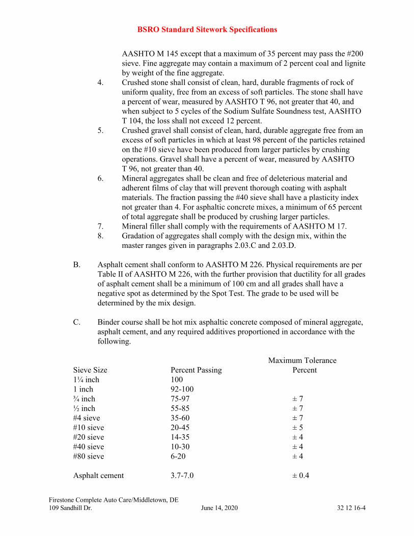
BSRO Standard Sitework Specifications
Firestone Complete Auto Care/Middletown, DE
109 Sandhill Dr. June 14, 2020 32 12 16-4
AASHTO M 145 except that a maximum of 35 percent may pass the #200
sieve. Fine aggregate may contain a maximum of 2 percent coal and lignite
by weight of the fine aggregate.
4. Crushed stone shall consist of clean, hard, durable fragments of rock of
uniform quality, free from an excess of soft particles. The stone shall have
a percent of wear, measured by AASHTO T 96, not greater that 40, and
when subject to 5 cycles of the Sodium Sulfate Soundness test, AASHTO
T 104, the loss shall not exceed 12 percent.
5. Crushed gravel shall consist of clean, hard, durable aggregate free from an
excess of soft particles in which at least 98 percent of the particles retained
on the #10 sieve have been produced from larger particles by crushing
operations. Gravel shall have a percent of wear, measured by AASHTO
T 96, not greater than 40.
6. Mineral aggregates shall be clean and free of deleterious material and
adherent films of clay that will prevent thorough coating with asphalt
materials. The fraction passing the #40 sieve shall have a plasticity index
not greater than 4. For asphaltic concrete mixes, a minimum of 65 percent
of total aggregate shall be produced by crushing larger particles.
7. Mineral filler shall comply with the requirements of AASHTO M 17.
8. Gradation of aggregates shall comply with the design mix, within the
master ranges given in paragraphs 2.03.C and 2.03.D.
B. Asphalt cement shall conform to AASHTO M 226. Physical requirements are per
Table II of AASHTO M 226, with the further provision that ductility for all grades
of asphalt cement shall be a minimum of 100 cm and all grades shall have a
negative spot as determined by the Spot Test. The grade to be used will be
determined by the mix design.
C. Binder course shall be hot mix asphaltic concrete composed of mineral aggregate,
asphalt cement, and any required additives proportioned in accordance with the
following.
Maximum Tolerance
Sieve Size Percent Passing Percent
1¼ inch 100
1 inch 92-100
¾ inch 75-97 ± 7
½ inch 55-85 ± 7
#4 sieve 35-60 ± 7
#10 sieve 20-45 ± 5
#20 sieve 14-35 ± 4
#40 sieve 10-30 ± 4
#80 sieve 6-20 ± 4
Asphalt cement 3.7-7.0 ± 0.4
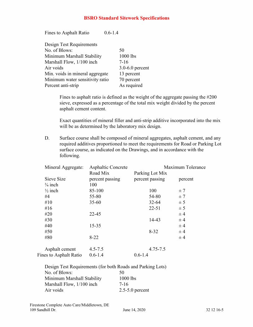
BSRO Standard Sitework Specifications
Firestone Complete Auto Care/Middletown, DE
109 Sandhill Dr. June 14, 2020 32 12 16-5
Fines to Asphalt Ratio 0.6-1.4
Design Test Requirements
No. of Blows: 50
Minimum Marshall Stability 1000 lbs
Marshall Flow, 1/100 inch 7-16
Air voids 3.0-6.0 percent
Min. voids in mineral aggregate 13 percent
Minimum water sensitivity ratio 70 percent
Percent anti-strip As required
Fines to asphalt ratio is defined as the weight of the aggregate passing the #200
sieve, expressed as a percentage of the total mix weight divided by the percent
asphalt cement content.
Exact quantities of mineral filler and anti-strip additive incorporated into the mix
will be as determined by the laboratory mix design.
D. Surface course shall be composed of mineral aggregates, asphalt cement, and any
required additives proportioned to meet the requirements for Road or Parking Lot
surface course, as indicated on the Drawings, and in accordance with the
following.
Mineral Aggregate: Asphaltic Concrete Maximum Tolerance
Road Mix Parking Lot Mix
Sieve Size percent passing percent passing percent
¾ inch 100
½ inch 85-100 100 ± 7
#4 55-80 54-80 ± 7
#10 35-60 32-64 ± 5
#16 22-51 ± 5
#20 22-45 ± 4
#30 14-43 ± 4
#40 15-35 ± 4
#50 8-32 ± 4
#80 8-22 ± 4
Asphalt cement 4.5-7.5 4.75-7.5
Fines to Asphalt Ratio 0.6-1.4 0.6-1.4
Design Test Requirements (for both Roads and Parking Lots)
No. of Blows: 50
Minimum Marshall Stability 1000 lbs
Marshall Flow, 1/100 inch 7-16
Air voids 2.5-5.0 percent

BSRO Standard Sitework Specifications
Firestone Complete Auto Care/Middletown, DE
109 Sandhill Dr. June 14, 2020 32 12 16-6
Min. voids in mineral aggregate 14 percent
Minimum water sensitivity ratio 70 percent
Percent anti-strip As required
Exact quantities of mineral filler and anti-strip additives incorporated into the mix
will be as determined by the laboratory mix design.
Surface course shall contain not more than 60 percent limestone aggregate in the
coarse mineral aggregate fraction. When limestone is the primary coarse mineral
aggregate, crushed sandstone, crushed siliceous gravel, syenite, novaculite, or
crushed slag shall be used as the remaining coarse mineral fraction. The portion
retained on the #10 sieve shall have an insoluble residue of not less than 85
percent when tested in a 1:1 solution of hydrochloric acid and water.
2.04 MIX DESIGN
A. A special mix design prepared specifically for this project will not be required.
Submit for review the mix design in use at the mixing plant for its regular supply
of the mixes specified.
B. Mix designs shall be prepared by laboratory analysis in accordance with the
requirements of the specifications. Mix design preparation shall comply with
applicable provisions of State DOT specifications and practices.
2.05 SOURCE QUALITY CONTROL
A. Contractor is responsible for quality control testing of the ACHM mixtures to be
incorporated in the work prior to their placement in the work, in accordance with
provisions in Division 01 of the Project Manual.
B. Tests shall be conducted by the mixing plant, as part of a regular quality control
program. Such tests shall be of the type and at the frequency required to
demonstrate that the mixing plant is producing mixtures in conformance with
required design mixes.
C. If required by Owner or Owner’s Representative, submit a copy of standing
quality control program in use at the mixing plant.
D. If required by Owner or Owner’s Representative, submit copies of testing records
of tests conducted at the mixing plant on the ACHM products delivered for this
project. Such tests will be ordered if Owner or Owner’s Representative has reason
to believe the ACHM mixtures supplied are not in compliance with the
specifications, or if the mixtures appear to result in overly difficult placement or
compaction such that specified results are not obtained. Such testing, if ordered,
may include: extraction tests, and sieve analysis (AASHTO T 30) of the extracted

BSRO Standard Sitework Specifications
Firestone Complete Auto Care/Middletown, DE
109 Sandhill Dr. June 14, 2020 32 12 16-7
aggregate; nuclear asphalt content gauge, and sieve analysis (AASHTO T 30) of
the aggregate sample. Additional tests required for further evaluation of the
mixture will be as needed to prove the adequacy of the mixture.
PART 3 EXECUTION
3.01 EXAMINATION
A. Examine the areas and conditions under which work will be performed.
Conditions detrimental to timely and proper execution of this work shall be
corrected. No work shall be done until unsatisfactory conditions are corrected.
3.02 PREPARATION
A. Before application of each course, prepare the existing course to receive the new
course. Such preparation may include filling sags and depressions with asphalt
binder or surface course mixtures. Accomplish this work by hand, blade grader, or
mechanical spreader methods. Featheredge to a smooth and even surface around
the edges of these areas. Prime coat or tack coat as applicable before placing this
material. Examine base course to verify that the lines and grades conform to the
requirements of the Drawings and Specifications.
B. Clean away loose and foreign materials.
C. Paint contact surfaces of curbing, gutters, manholes, and other structures with a
thin coating of rapid curing cutback asphalt or emulsified asphalt.
3.03 INSTALLATION
A. Prime Coat
1. Clean surface to be treated with prime coat of dust, dirt, and loose or
foreign material by sweeping with mechanical brooms immediately
preceding application of prime coat. Take care to clean but not loosen or
dislodge embedded aggregate in base course. Remove patches of asphalt,
dirt, or other material which does not form an integral part of the surface
to be treated.
2. Perform cleaning only far enough in advance of the application to ensure
the surface being properly prepared at the time of application.
3. Spray prime coat material uniformly over surface by means of mechanical
pressure distributor at the rate of 0.25 gallons per square yard, or as
recommended by the manufacturer for project conditions. Remove surplus
material that collects in surface depressions.
4. Allow prime coat to cure per manufacturer's recommendations before
application of asphalt material. No material for a succeeding course shall
BSRO Standard Sitework Specifications
Firestone Complete Auto Care/Middletown, DE
109 Sandhill Dr. June 14, 2020 32 12 16-8
be placed on a primed base course until the prime coat has cured
sufficiently to prevent damage by hauling operations.
5. Do not apply when air temperature is below 45 degrees F.
6. Observe special precautions to ensure uniform distribution of prime coat
material. Adjust and operate distributor so as to evenly distribute material.
Remove excess quantities on the road surface caused by stopping or
starting the distributor, by overflow, leakage, or otherwise.
7. Apply prime coat material only at temperatures within manufacturer's
recommendations.
8. Repair prime coat that becomes damaged.
B. Apply tack coat in a manner similar to that described in paragraph 3.03.A for
prime coat. Apply at the rate of 0.02 to 0.03 gallons per square yard. Apply tack
coat sufficiently in advance of asphalt course to allow proper curing of the tack
coat material but not so far in advance as to lose its adhesiveness as a result of
being covered with dust or foreign material. If tack coat becomes damaged or
covered with foreign material, clean and re-treat with tack coat as required.
C. Binder course construction: Refer to State DOT specifications to supplement these
requirements. Binder course shall be constructed to the following standards.
Minimum Density, percent of theoretical 92.0
Maximum Moisture, percent (Roadway) 0.75
1. Place mixture on prepared surface, spread, and strike off to line, grade, and
elevation required. Place mixture only on a base that shown no evidence of
free moisture, and when weather conditions are suitable. Owner or
Owner’s Representative may permit work of this character to continue
when overtaken by sudden rains to utilize materials that may be in transit
from the mixing plant to the site.
2. Mixture shall be delivered to the paver within recommended compaction
temperature range according to the design mix. Do not place binder course
on roadway at a temperature lower than 250 degrees F.
3. Hand spreading is permitted only in areas inaccessible to pavement.
4. Paver shall uniformly distribute and compact mixture in front of the screed
for full width being paved. Finished surface shall be smooth and of
uniform texture.
5. Screed or strike-off assembly shall effectively produce a finished surface
of required evenness and texture without tearing, shoving, or gouging
mixture.
6. Operate mixer at forward speeds consistent with satisfactory laying of
mixture. Match speed of paver with mixing plant production rate and
number of hauling units.
7. Establish edge of binder course by string or chalk line for at least 500 feet
ahead of spreading operation.
BSRO Standard Sitework Specifications
Firestone Complete Auto Care/Middletown, DE
109 Sandhill Dr. June 14, 2020 32 12 16-9
8. Thoroughly compact mixture after spreading by rolling as soon as it will
bear weight of rollers without undue displacement.
9. Establish an optimum rolling pattern at beginning of placement of each
mix design.
10. The number, weight, and type of rollers, and the optimum rolling pattern
shall be such that the specified density and surface requirements are
consistently attained while mixture is in a workable condition. Rollers
which produce excessive crushing of aggregate particles will not be
permitted.
11. Following the breakdown rolling operation and as soon as the mat will
support the roller without displacement, pass pneumatic roller over binder
course a sufficient number of times to knead and seal entire mat being
placed.
12. Exercise due care when using vibratory rollers to prevent any deterioration
of material caused by excessive rolling or vibration. Operate vibratory
rollers in such a manner that overlap of adjacent passes shall be held to a
minimum.
13. Start rolling longitudinally at the low edge and proceed toward the higher
portion of the mat. When paving abutting a previously placed lane,
longitudinal joint shall be rolled first followed by regular rolling
procedure. Terminate alternate passes of roller 3 feet from any preceding
stop. Do not stop rollers perpendicular to centerline of traveled way.
14. Restrict speed of roller to avoid displacement of hot mixture, and do not
exceed 3 mph. Operate roller in such a manner that no displacement of the
mat will occur. Rolling shall proceed continuously until all roller marks
are eliminated and required density attained. Keep rollers moist for full
width of roller to prevent adhesion of asphalt mixture to roller. Excess
water will not be permitted.
15. Do not pass rollers over unprotected end of a freshly laid mixture. Form
transverse joints by cutting back on previous run to expose full depth of
the course. Use a brush coat of asphalt material on contact surfaces of
transverse joints just before additional mixture is placed against previously
placed material.
16. Upon completion of rolling operations, surface shall be smooth and of
uniform texture.
D. Surface course construction: Refer to State DOT specifications to supplement
these requirements. Surface course shall be constructed to the following standards.
Minimum Density, percent of theoretical 92.0
Maximum Moisture, percent (Roadway) 0.75
Surface course construction shall comply with the requirements of Paragraph
3.03.C, and with the following additional requirements.
BSRO Standard Sitework Specifications
Firestone Complete Auto Care/Middletown, DE
109 Sandhill Dr. June 14, 2020 32 12 16-10
1. Offset longitudinal joint in one layer by approximately 6 inches from the
layer below. However, in any non-parking lot pavement joint in top layer
shall be at the centerline of pavement or at lane lines. General casting back
of material or hand raking material onto surface will not be permitted.
2. Establish edge of surface course at least 500 feet ahead of spreading
operation.
3. Finished surface, when checked with a 10 foot straight edge parallel to the
centerline, shall show no variation more than 1/8 inch for surface course.
3.04 FIELD QUALITY CONTROL
A. Responsibility for quality control testing of the completed pavement is specified
in Division 01 of the Project Manual. Tests to be taken and their frequency will be
determined by Owner or Owner’s Representative. Tests may include coring for
depth and laboratory density, in-place density, and straight edge for smoothness.
Density of compacted mixture shall be in accordance with AASHTO T 166.
B. If testing shows deficiencies, correct deficiencies by means satisfactory to Owner
or Owner’s Representative prior to beginning additional work. If deficiencies
appear to be the result of variation from approved mix design, an inadequate mix
design or materials (as opposed to workmanship), stop operations until corrections
can be made at the mixture source. If deficiencies are a result of workmanship,
adjust operations and equipment to achieve the specified results.
3.05 CLEANING
A. Clean surface of pavement as required of debris and loose material after
compaction and before final acceptance.
B. Clean ACHM splatter or excess material from curbs, gutters, drainage structures,
and other places where it has been placed and exceeds the limits of paving
indicated on the Drawings.
END OF SECTION 32 12 16
BSRO Standard Sitework Specifications
Firestone Complete Auto Care/Middletown, DE
109 Sandhill Dr. June 14, 2020 32 13 13-1
SECTION 32 13 13
PORTLAND CEMENT CONCRETE PAVING
PART 1 GENERAL
1.01 SECTION INCLUDES
A. Preparation and placement of Portland cement concrete roads and entrances.
1.02 RELATED SECTIONS
A. Section 31 00 10 – Site Preparation
B. Section 31 00 20 – Earthwork
C. Section 31 05 16 – Aggregate Material
D. Section 31 23 03 – Excavation, Backfilling, and Compaction for Pavement
E. Section 32 11 23 – Paving Base Course
F. Drawings
1.03 REFERENCE STANDARDS
A. State Department of Transportation standard specifications for highway
construction, as applicable, latest edition
B. American Concrete Institute (ACI) latest edition
304R Guide for Measuring, Mixing, Transporting, and Placing Concrete
305R Hot Weather Concreting
306R Cold Weather Concreting
308 Standard Practice for Curing Concrete
318 Building Code Requirements for Reinforced Concrete
347 Recommended Practice for Concrete Formwork
C. ASTM International (ASTM) latest edition
A 185 Steel Welded Wire Fabric, Plain, for Concrete Reinforcement
A 497 Steel Welded Wire Fabric, Deformed, for Concrete Reinforcement
A 615 Deformed and Plain Billet-Steel for Concrete Reinforcement
C 31 Making and Curing Concrete Test Specimens in the Field
C 33 Concrete Aggregates
C 39 Compressive Strength of Cylindrical Concrete Specimens
C 42 Method of Obtaining and Testing Drilled Cores
C 94 Specification for Ready-Mixed Concrete
C 150 Portland Cement
C 260 Air-Entraining Admixtures for Concrete
C 309 Liquid Membrane-Forming Compounds for Curing Concrete
C 494 Chemical Admixtures for Concrete
BSRO Standard Sitework Specifications
Firestone Complete Auto Care/Middletown, DE
109 Sandhill Dr. June 14, 2020 32 13 13-2
D 1751 Preformed Expansion Joint Fillers for Concrete Paving and Structural
Construction (Non-extruding and Resilient Bituminous Types)
D. Federal Standard
FS TT-C-800 – Curing Compound, Concrete, for New and Existing Surfaces
E. Concrete Reinforcing Steel Institute (CRSI) latest edition
CRSI-MSP Manual of Standard Practice
CRSI 63 Recommended Practice for Placing Reinforcing Bars
CRSI 65 Recommended Practice for Placing Bar Supports
F. American Association of State Highway and Transportation Officials (AASHTO)
latest edition
1.04 QUALITY ASSURANCE
A. An independent testing laboratory, selected by Owner and paid by Owner, shall
randomly core pavement at a minimum rate of 1 core per 20,000 sq. ft of
pavement, with a minimum of 3 cores from heavy duty areas and 3 cores from
light duty areas. Core shall be tested for thickness and quality of aggregate
distribution. Patch core holes immediately with Portland cement concrete and
finish to provide level surface as specified.
B. Establish and maintain required lines, grades and elevations.
C. Check surface areas at intervals necessary to eliminate ponding areas. Remove
and replace unacceptable paving as directed by Owner or Owner’s Representative.
1.05 SUBMITTALS
A. Submit materials certificate to Owner or Owner’s Representative which is signed
by materials producer and Contractor, certifying that materials comply with, or
exceed, requirements specified herein.
PART 2 PRODUCTS
2.01 MATERIALS
A. Forms: Steel, wood, or other suitable material of size and strength to resist
movement during concrete placement and to retain horizontal and vertical
alignment until removal. Use straight forms, free of distortion and defects. Use
flexible spring steel forms or laminated boards to form radius bends as required.
Coat forms with a non-staining type of coating that will not discolor or deface
surface of concrete.

BSRO Standard Sitework Specifications
Firestone Complete Auto Care/Middletown, DE
109 Sandhill Dr. June 14, 2020 32 13 13-3
B. Welded Wire Mesh: Welded plain cold-drawn steel wire fabric, ASTM A 185.
Furnish in flat sheets, not rolls, unless approved by Owner or Owner’s
Representative.
C. Reinforcing Bars: Deformed steel bars, ASTM A 615, Grade 40.
D. Concrete Materials:
1. Portland Cement conforming to ASTM C 150, Type 1 or 1A, Type III or
IIIA (high early strength) may be used if specifically approved by Owner or
Owner’s Representative.
2. Coarse Aggregates conforming to 3/4 inches maximum to No. 4 minimum
size.
3. Fine Aggregates conforming to ASTM C 33
4. Water shall conforming to ASTM C 94
E. Joint Fillers: Resilient premolded bituminous impregnated fiberboard units
complying with ASTM D 1751 or AASHTO M 213.
F. Joint Sealants: Non-priming, pourable, self-leveling polyurethane. Acceptable
sealants are Sonneborn "Sonolastic Paving Joint Sealant", Sonneborn "Sonomeric
CT 1 Sealant", Sonneborn "Sonomeric CT 2 Sealant", Mameco "Vulken 245", or
Woodmont Products "Chem-Caulk".
2.02 MIX DESIGN AND TESTING
A. Design mix shall produce normal weight concrete consisting of Portland cement,
aggregate, water-reducing admixture when approved by Owner or Owner’s
Representative, air-entraining admixture, and water to produce following
properties:
1. Compressive Strength: 4,000 psi, minimum at 28 days, unless otherwise
indicated on the Drawings.
2. Slump Range: 3 to 5-inches at time of placement
3. Air Entrainment: 5 to 8 percent
PART 3 EXECUTION
3.01 PREPARATION
A. Proof-roll prepared base material surface to check for unstable areas. Paving work
shall begin only after unsuitable areas have been corrected and are ready to
receive paving.
BSRO Standard Sitework Specifications
Firestone Complete Auto Care/Middletown, DE
109 Sandhill Dr. June 14, 2020 32 13 13-4
B. Remove loose material from compacted base material surface to produce firm,
smooth surface immediately before placing concrete.
3.02 INSTALLATION
A. Form Construction
1. Set forms to required lines, grades and elevations, rigidly braced and
secured in accordance with ACI 347.
2. Install sufficient quantity of forms to allow continuance of work; forms to
remain in place a minimum of 24 hours after concrete placement and
finishing operations.
3. Check completed formwork for grade and alignment to following
tolerances:
Top of forms not more than 1/8-inch in 10 feet
Vertical face on longitudinal axis, not more than 1/4-inch in 10 feet
4. Clean forms after each use and coat with form release agent as often as
required to ensure separation from concrete without damage to concrete.
B. Reinforcement: Locate, place, and support reinforcement in accordance with
CRSI 63 and CRSI 65.
C. Concrete Placement
1. Place concrete in accordance with requirements of ACI 304R, 305R and
306R.
2. Do not place concrete until base material and forms have been checked for
line and grade. Moisten base material if required to provide uniform
dampened condition at time concrete is placed. Concrete shall not be placed
around manholes or other structures until they are at required finish
elevation and alignment.
3. Place concrete using methods which prevent segregation of mix.
Consolidate concrete along face of forms and adjacent to transverse joints
with internal vibrator. Keep vibrator away from joint assemblies,
reinforcement, or other structural components. Consolidate with care to
prevent dislocation of reinforcing, dowels, and joint devices.
4. Deposit and spread concrete in a continuous operation between transverse
joints. If interrupted for more than 1/2 hour, place construction joint that
corresponds to the established joint pattern.
D. Joint Construction: Construct expansion, weakened-plane control or contraction,
and construction joints straight with face perpendicular to concrete surface.
Construct transverse joints perpendicular to longitudinal joints, unless otherwise
indicated on the Drawings. Where the Drawings do not provide a specific joint
pattern, construct joints to the following requirements.

BSRO Standard Sitework Specifications
Firestone Complete Auto Care/Middletown, DE
109 Sandhill Dr. June 14, 2020 32 13 13-5
1. Weakened-Plane Control or Contraction Joints: Provide joints at a
maximum spacing of 15 feet each way and at a depth not less than 1/4 of the
concrete thickness and as follows:
a. Form tooled joints in fresh concrete by grooving top with the
recommended tool to provide a rounded edge having a 3/16 inch
radius.
b. Form sawed joints using powered saws equipped with shatterproof
abrasive or diamond-rimmed blades. Cut joints into hardened concrete
as soon as surface will support the saw and not be torn, abraded, or
otherwise damaged by cutting action.
2. Construction Joints: Provide joints that correspond to established joint
pattern at end of placements and at locations where placement operations
are stopped for period of more than 1/2 hour, except where such placements
terminate at expansion joints. Construct joints using standard metal
keyway-section forms unless otherwise indicated on the Drawings.
3. Expansion Joints: Locate expansion joints at a maximum of 180 feet o.c.
each way. Provide premolded joint filler for expansion joints abutting
concrete curbs, catch basins, manholes, inlets, structures, sidewalks, and
other fixed objects.
E. Joint Fillers: Extend joint fillers full-width and depth of joint, and not less than
1/2-inch or more than 1-inch below finished surface where joint sealer is
indicated. Furnish joint fillers in 1-piece lengths for full width being placed,
wherever possible. Where more than 1 length is required, lace or clip joint filler
sections together.
F. Joint Sealants: Joints shall be sealed with approved exterior pavement joint
sealants and shall be installed in accordance with manufacturer's
recommendations.
3.03 CONCRETE FINISHING
A. After striking off and consolidating concrete, smooth surface by screeding and
floating. Adjust floating to compact surface and produce uniform texture. After
floating, test surface for trueness with 10 foot straightedge. Distribute concrete as
required to remove surface irregularities and refloat repaired areas to provide
continuous smooth finish.
B. Work edges of slabs and formed joints with edging tool, rounding edge to 3/16-
inch radius. Eliminate tool marks on concrete surface. After completion of
floating and trowelling, when excess moisture or surface sheen has disappeared,
complete surface finishing, as follows:
BSRO Standard Sitework Specifications
Firestone Complete Auto Care/Middletown, DE
109 Sandhill Dr. June 14, 2020 32 13 13-6
1. Inclined Slab Surfaces: Provide coarse, nonslip finish by scoring surface
with stiff-bristled broom perpendicular to flow of traffic.
2. Paving: Provide coarse, nonslip finish by scoring surface with stiff-bristled
broom perpendicular to flow of traffic.
C. Do not remove forms for 24 hours after concrete has been placed. After form
removal, clean ends of joints and point up minor honeycombed areas. Remove
and replace areas or sections with major defects, as directed by Owner or Owner’s
Representative.
D. Protect and cure finished concrete paving using acceptable moist-curing methods,
more particularly described in "water-curing" section of ACI 308.
3.04 CLEANING AND ADJUSTING
A. Sweep concrete pavement and wash free of stains, discolorations, dirt, and other
foreign material just prior to final inspection.
B. Protect concrete from damage until acceptance of work. Exclude traffic from
pavement for at least 14 days after placement. When construction traffic is
permitted, maintain pavement as clean as possible by removing surface stains and
spillage of materials.
END OF SECTION 32 13 13
BSRO Standard Sitework Specifications
Firestone Complete Auto Care/Middletown, DE
109 Sandhill Dr. June 14, 2020 32 16 14-1
SECTION 32 16 14
CURBS AND SIDEWALKS
PART 1 GENERAL
1.01 SECTION INCLUDES
A. Preparation and placement of combination Portland cement concrete curb and
gutter.
B. Preparation and placement of Portland cement concrete curb.
C. Preparation and placement of Portland cement concrete sidewalk.
1.02 RELATED SECTIONS
A. Section 31 00 10 – Site Preparation
B. Section 31 00 20 – Earthwork
C. Section 31 23 03 – Excavation, Backfill, and Compaction for Pavement
D. Section 31 05 16 – Aggregate Material
E. Section 32 11 23 – Paving Base Course
F. Section 32 13 13 – Portland Cement Concrete Paving
G. State Highway Department Standard Specifications
H. Drawings
1.03 REFERENCE STANDARDS
A. American Concrete Institute (ACI)
304R Guide for Measuring, Mixing, Transporting, and Placing Concrete
305R Hot Weather Concreting
306R Cold Weather Concreting
308 Standard Practice for Curing Concrete
318 Building Code Requirements for Reinforced Concrete
347 Recommended Practice for Concrete Formwork
B. ASTM International (ASTM)
A185 Steel Welded Wire Fabric, Plain, for Concrete Reinforcement
A497 Steel Welded Wire Fabric, Deformed, for Concrete Reinforcement
A 615 Deformed and Plain Billet-Steel for Concrete Reinforcement
C 31 Making and Curing Concrete Test Specimens in the Field
C 33 Concrete Aggregates
C 39 Compressive strength of Cylindrical Concrete Specimens
C 42 Method of Obtaining and Testing Drilled Cores
C 94 Specification for Ready-Mixed Concrete
C 150 Portland Cement
BSRO Standard Sitework Specifications
Firestone Complete Auto Care/Middletown, DE
109 Sandhill Dr. June 14, 2020 32 16 14-2
C 260 Air-Entraining Admixtures for Concrete
C 309 Liquid Membrane-Forming Compounds for Curing Concrete
C 494 Chemical Admixtures for Concrete
D 1751 Preformed Expansion Joint Fillers for Concrete Paving and Structural
Construction (Non-extruding and Resilient Bituminous Types)
D 3406 Joint Sealant, Hot-Applied, Elastomeric Type, for Portland Cement
Concrete Pavement.
D 5893 Cold Applied, single Component Chemically Curing Silicone Joint
Sealant for Portland Cement Concrete Pavement
C. Federal Specifications
FS TT-C-800 – Curing Compound, Concrete, for New and Existing Surfaces.
FS HH-F-341 F(1) – Filler, Expansion Joint, Bituminous (Asphalt or Tar) and
Non-bituminous (Preformed) for Concrete
D. Concrete Reinforcing Steel Institute (CRSI)
CRSI MSP Manual of Standard Practice
CRSI 63 Recommended Practice for Placing Reinforcing Bars
CRSI 65 Recommended Practice for Placing Bar Supports
E. American Association of State Highway and Transportation Officials (AASHTO)
AASHTO M 182 – Burlap Cloth Made From Jute or Kenaf
AASHTO M 324 – Joint and Crack Sealants, Hot Applied, for Asphalt and
Concrete Pavements
1.04 SUBMITTALS
A. Submit materials certificate, signed by materials producer and Contractor, to the
independent testing laboratory, certifying that materials comply with, or exceed,
requirements specified herein.
1.05 PROJECT CONDITIONS
A. Maintain access for vehicular and pedestrian traffic as required for other
construction activities. Utilize temporary striping, flagmen, barricades, warning
signs, and warning lights as required.
1.06 QUALITY ASSURANCE
A. Construct items under this section using superintendents, foremen, and workers
experienced in this type of construction.
B. Use equipment in good running conditions, suitable for continuous use.
BSRO Standard Sitework Specifications
Firestone Complete Auto Care/Middletown, DE
109 Sandhill Dr. June 14, 2020 32 16 14-3
C. Sidewalks have been designed to comply with slope requirements of the
Americans with Disabilities Act (A.D.A.). Completed sidewalks will be checked
for transverse and longitudinal slope. Any section of sidewalk found to not
comply with A.D.A. requirements will be removed and replace at no expense to
Owner.
PART 2 PRODUCTS
2.01 MATERIALS
A. Forms: Steel, wood, or other suitable material of size and strength to resist
movement during concrete placement and to retain horizontal and vertical
alignment until removal. Use straight forms, free of distortion and defects. Use
flexible spring steel forms or laminated boards to form radius bends as required.
Forms shall be of depth equal to depth of curbing or sidewalk, and so designed as
to permit secure fastening together at tops. Coat forms with a non-staining type of
coating that will not discolor or deface surface of concrete.
B. Welded Wire Mesh: Welded plain cold-drawn steel wire fabric, ASTM A 185.
Furnish in flat sheets, not rolls, unless approved by Owner or Owner’s
Representative.
C. Reinforcing Bars: Deformed steel bars, ASTM A 615, Grade 40.
D. Concrete Materials:
1. Portland Cement conforming to ASTM C 150, Type 1 or 1A. Type III or
IIIA (high early strength) may be used if specifically approved by Owner or
Owner’s Representative.
2. Coarse Aggregate conforming to 3/4 inch maximum to No. 4 minimum size
3. Fine Aggregate conforming to ASTM C 33
4. Water complying with ASTM C 94
E. Joint Fillers: Resilient pre-molded bituminous impregnated fiberboard units
complying with ASTM D 1751 or FS HH-F-341, Type II, Class A
F. Joint Sealers: Non-priming, pourable, self-leveling polyurethane, generally
complying with ASTM D 3406 or D 5893. Acceptable manufacturers are
Sonneborn, Mameco, Woodmont Products, or Thoro.
2.02 MIX DESIGN AND TESTING
A. Design mix shall produce normal weight concrete consisting of Portland cement,
aggregate, water-reducing admixture (when approved by Owner or Owner’s
Representative), air-entraining admixture, and water, to produce following:

BSRO Standard Sitework Specifications
Firestone Complete Auto Care/Middletown, DE
109 Sandhill Dr. June 14, 2020 32 16 14-4
1. Compressive Strength: 3,500 psi, minimum at 28 days, unless otherwise
indicated on the Drawings.
2. Slump Range: 2 to 5 inches at time of placement
3. Air Entrainment: 5 to 8 percent
PART 3 EXECUTION
3.01 PREPARATION
A. Establish and maintain required lines, grades, and elevations.
B. Check surface at intervals necessary to eliminate ponding areas. Remove and
replace unacceptable work as directed by Owner or Owner’s Representative.
C. Proof roll prepared base material surface to check for unsuitable areas. Concrete
work shall begin only after unsuitable areas have been corrected and are ready to
receive concrete.
D. Immediately before placing concrete, remove loose material from compacted base
surface to produce firm, smooth surface.
3.02 CONSTRUCTION
A. Form Construction
1. Set forms to required lines grades and elevations, rigidly braced and secured
in accordance with ACI 347.
2. Install sufficient quantity of forms to allow continuity of work, allowing
forms to remain in place a minimum of 24 hours after concrete placement
and finishing operations.
3. Check completed formwork for grade and alignment to following
tolerances:
Top of forms not more than 1/8 inch in 10 feet
Vertical face on longitudinal axis, not more than 1/4 inch in 10 feet
4. Clean forms after each use and coat with form release agent as often as
required to ensure separation from concrete without damage to concrete.
B. Reinforcement: Locate, place, and support reinforcement in accordance with
CRSI 63 and CRSI 65.
C. Concrete Placement
1. Place concrete in accordance with requirements of ACI 304R, and where
applicable 305R and 306R.
2. Do not place concrete until base material and forms have been checked for
line and grade. Moisten base material if required to provide uniform
BSRO Standard Sitework Specifications
Firestone Complete Auto Care/Middletown, DE
109 Sandhill Dr. June 14, 2020 32 16 14-5
dampened condition at time concrete is placed. Concrete shall not be placed
around manholes or other structures until they are at required finish
elevation and alignment.
3. Place concrete using methods which prevent segregation of mix.
Consolidate concrete along face of forms and adjacent to transverse joints
with internal vibrator. Keep vibrator away from joint assemblies,
reinforcement, or other structural components. Consolidate with care to
prevent dislocation of reinforcing, dowels, and joint devices.
4. Deposit and spread concrete in a continuous operation between transverse
joints. If interrupted for more than 1/2 hour, place construction joint that
corresponds to the established joint pattern when adjoining concrete paving.
5. Extrusion machine may be used for curb and gutter placement. Machine
placement must be at required cross section, line, grade, finish, and jointing
as specified for formed concrete. If Owner or Owner’s Representative
determines results are not acceptable, remove and replace with formed
concrete as specified herein.
D. Joint Construction
1. Transverse Contraction Joints: Concrete curb and gutter, combination
concrete curb and gutter, and concrete sidewalk shall be constructed as
indicated on the Drawings. Joints between sections shall be formed either:
by steel templates, 1/8 inch in thickness, of length equal to width of curb
and gutter, and with depth which will penetrate not less than 2 inches below
surface of curb and gutter; or by sawing as specified in section 32 13 13
paragraph 3.02.D to a depth of not less than 2 inches below surface of curb
and gutter. Steel templates, if used, shall be left in place until concrete has
set enough to hold its shape, but shall be removed while forms are still in
place. Unless local practice dictates otherwise, space contraction joints in
concrete curb and gutter not greater than 15 feet apart.
2. Longitudinal Construction Joints: Concrete curb or combination concrete
curb and gutter, where specified on the Drawings, shall be tied to concrete
pavement with 1/2 inch round deformed reinforcement bars of length and
spacing shown on the Drawings.
3. Transverse Expansion Joints: Concrete curb, combination concrete curb and
gutter, or concrete sidewalk shall have pre-molded joint filler cut to exact
cross section of curb, gutter, or sidewalk. Locate expansion joints at a
maximum of 180 feet on center and corresponding to established joint
pattern when adjoining concrete paving.
E. Joint Fillers: Extend expansion joint fillers full-width and depth of joint. Where
joint sealer is indicated, joint fillers shall be not less than 1/2 inch or more than 1
inch below finished surface. Where joint sealant is not used, joint fillers shall not
BSRO Standard Sitework Specifications
Firestone Complete Auto Care/Middletown, DE
109 Sandhill Dr. June 14, 2020 32 16 14-6
extend above the adjacent finished concrete surfaces. Furnish joint fillers in
1-piece lengths for full width being placed, wherever possible. Where more than 1
length is required, lace or clip joint filler sections together.
F. Joint Sealants: Seal joints with approved exterior pavement joint sealants. Install
sealants in accordance with manufacturer's recommendations.
3.03 CONCRETE FINISHING
A. After striking off and consolidating concrete, smooth surface by screeding,
floating and hand trowelling. Adjust floating to compact surface and produce
uniform texture. After floating, test surface for trueness with 10 foot straightedge.
Curb and gutter shall not vary from plan grades more than 1/4 inch in 10 feet.
Distribute concrete as required to remove surface irregularities, and refloat
repaired areas to provide continuous smooth finish.
B. Work edges of sidewalks, gutters, back top edge of curb, and formed joints with
edging tool, rounding edge to 3/16 inch radius. Eliminate tool marks on concrete
surface. After completion of floating and trowelling, when excess moisture or
surface sheen has disappeared, broom finish by drawing fine-hair broom across
surface perpendicular to flow of traffic. Repeat operation as necessary to produce
fine line texture.
C. Do not remove forms for 24 hours after concrete has been placed. After form
removal, clean ends of joints and point up minor honeycombed areas. Remove
and replace areas or sections with major defects, as directed Owner or Owner’s
Representative.
D. Protect and cure finished concrete curb, combination curb and gutter, and
sidewalk using acceptable moist-curing methods, more particularly described in
"water-curing" section of ACI 308.
3.04 BACKFILL
A. After concrete has set sufficiently, spaces on either side of concrete curb,
combination concrete curb and gutter, or concrete sidewalk shall be refilled to
required elevation with suitable material compacted in accordance with Section
31 00 20.
3.05 CLEANING AND ADJUSTING
A. Sweep concrete curb, curb and gutter, and sidewalk and wash free of stains,
discolorations, dirt, and other foreign material prior to final inspection.
BSRO Standard Sitework Specifications
Firestone Complete Auto Care/Middletown, DE
109 Sandhill Dr. June 14, 2020 32 16 14-7
B. Protect concrete from damage until acceptance of work. Exclude traffic from curb,
curb and gutter or sidewalk for at least 14 days after placement. When
construction traffic is permitted, maintain all surfaces as clean as possible by
removing surface stains and spillage of materials.
End of Section 32 16 14
BSRO Standard Sitework Specifications
Firestone Complete Auto Care/Middletown, DE
109 Sandhill Dr. June 14, 2020 32 17 13-1
SECTION 32 17 13
PRECAST CONCRETE WHEEL STOPS
PART 1 GENERAL
1.01 SECTION INCLUDES
A. Furnish and install precast concrete wheel stops at parking spaces in the locations
indicated on the drawings.
1.02 UNIT PRICES
A. Unit prices for work covered under this section are defined in Section 01 45 01,
including incidentals, related work, method of measurement, if any, and partial
payment provisions.
1.03 SUBMITTALS
A. If requested by Owner or Owner’s Representative, submit manufacturer’s data,
cataloge pages, etc. for the wheel stops.
1.04 QUALITY ASSURANCE
A. Precast concrete wheel stops shall be the product of a manufacturer regularly
engaged in the manufacture of these units.
B. Units precast at the job site are not acceptable.
1.05 DELIVERY, STORAGE, AND HANDLING
A. Precast concrete wheel stop units received at site shall beimmediately inspected for
damage and defects. If paving work is essentially complete, distribute units in the
approximate locations where they will be installed. If paving work is not complete,
handle and store pipe in such a way to minimize damage.
PART 2 PRODUCTS
2.01 MATERIALS
A. Manufacter wheel stop units from Portland cement concrete, using aggregate
gradation appropriate for a small concrete unit.

BSRO Standard Sitework Specifications
Firestone Complete Auto Care/Middletown, DE
109 Sandhill Dr. June 14, 2020 32 17 13-2
B. Reinforcement shall be deformed bars, grade 40 or above.
C. Holes shall be factory drilled or cast in units.
D. Anchor bars shall be No. 6 deformed bar or larger.
2.02 FABRICATION
A. Shape of precast concrete unit shall be as indicated on the Drawings, as required
by local codes, or in accordance with customary local practice.
B. Precast units shall be fabricated under controlled conditions. Finish shall be
smooth, without honeycombing or irregular surface.
PART 3 EXECUTION
3.01 EXAMINATION
A. Examine units when they arrive at the job site. Reject units that are damaged, or
that are irregularly shaped or finished.
3.02 PREPARATION
A. Surface shall be finished before units are installed. Surface shall be smooth,
allowing entire bottom of unit to bear on pavement.
3.03 INSTALLATION
A. Drill hole in pavement slightly larger than anchor bar. Hole should be large
enough to allow bar to be easily hammered in place, but not so large that there is
annular space between bar and hole wall.
B. Install precast concrete wheel stop units over drilled holes. Hammer bars in place
through units. Bars shall not be pushed into holes using equipment. Any units
damaged during installation shall be removed and replaced.
3.04 CLEANING
A. Remove concrete or asphalt splatter that occurs after installation.
B. Remove striping paint from wheel stop, or replace wheel stop.

BSRO Standard Sitework Specifications
Firestone Complete Auto Care/Middletown, DE
109 Sandhill Dr. June 14, 2020 32 17 13-3
END OF SECTION 32 17 13

BSRO Standard Sitework Specifications
Firestone Complete Auto Care/Middletown, DE
109 Sandhill Dr. June 14, 2020 32 17 23-1
SECTION 32 17 23
PAVEMENT MARKING
PART 1 GENERAL
1.01 SECTION INCLUDES
A. Furnish and install paint pavement markings, including words, arrows, and
emblems, of the color and type specified, in accordance with the specifications
and at the locations indicated on the Drawings.
B. Pavement markings shall be reflectorized unless the Drawings indicate otherwise.
If the markings are not to be reflectorized, statements hereinafter about
reflectorized paint shall be considered void.
1.02 RELATED SECTIONS
A. Hot mix asphaltic concrete pavement is specified in section 32 12 16.
B. Portland cement concrete paving is specified in section 32 13 13.
C. Signage is specified in section 32 17 24.
1.03 REFERENCES
A. Federal Highway Administration (FHWA)
Manual on Uniform Traffic Control Devices (MUTCD).
B. American Association of State Highway and Transportation Officials (AASHTO)
M 247, “Glass Beads used in Traffic Paint”.
C. ASTM International (ASTM)
D 711 “No-Pick-Up Time of Traffic Paint”.
E 97 “Method of Test for Directional Reflectance Factor, 45 Deg 09 Deg, of
Opaque Specimens by Broad Band Filter Reflectometry
E 1347 “Standard Test Method for Color and Color-Difference Measurement
by Tristimulus Colorimetry”
D. Federal Specifications
Fed Spec TT-P-85e, “Paint, Traffic and Airfield Marking, Solvent Base”
1.04 SUBMITTALS
A. Submit product information of paint and glass beads to be used.

BSRO Standard Sitework Specifications
Firestone Complete Auto Care/Middletown, DE
109 Sandhill Dr. June 14, 2020 32 17 23-2
1.05 QUALITY ASSURANCE
A. Pavement marking shall be accomplished by workers who are experienced in
placing reflectorized paint pavement markings conforming to the MUTCD.
1.06 DELIVERY, STORAGE AND HANDLING
A. Paint shall be stored according to manufacturer’s recommendation.
PART 2 PRODUCTS
2.01 MATERIALS
A. Paint shall be a ready-mixed alkyd resin, chlorinated polyolefin, chlorinated
paraffin based white and yellow paint suitable for application on concrete and
bituminous pavements. Materials supplied shall be acceptable to the State DOT,
and shall be on any approved products list maintained by the DOT.
B. Paint shall have the property of angular reflectivity and be suitable as a binding
medium for glass beads placed on the surface of the wet paint in the amount of not
less than 6 pounds per gallon. Paint shall be homogeneous and well ground, shall
not settle badly, and shall be readily broken up with a paddle to a smooth, uniform
consistency. Paint shall be free from water or foreign matter and shall dry within
the specified time to a tough serviceable film. Paint shall be properly strained
during the final filling of containers and not more than one percent of coarse
particles and skins shall be retained on a #325 sieve when tested according to
Federal Test Method Standard No. 141 B.
C. Materials used in manufacture of paints shall meet the requirements herein
specified. Minor ingredients not specifically covered will be left to the discretion
of the manufacturer except that the finished product shall not be adversely
affected. Suitability of raw materials from different sources for use in paints shall
be the responsibility of the manufacturer.
D. Reactive or unstable products causing excessive viscosity or container instability
will be cause for rejection of the paint.
E. Paint shall conform, on a weight basis, to the composition requirements of the
formulation as closely as accepted good paint practice will permit. No intentional
variation will be permitted except for replacement of volatiles lost in processing.
Recognized test procedures will be used by Owner to determine the composition
of the finished paint.
BSRO Standard Sitework Specifications
Firestone Complete Auto Care/Middletown, DE
109 Sandhill Dr. June 14, 2020 32 17 23-3
F. Paint components shall conform with applicable State DOT standard construction
specifications.
G. Finished Paint Requirements.
1. Chlorinated polyolefin paint shall dry to no-pick-up in not more than 10
minutes without glass beads when tested in accordance with ASTM D 711
except that the film will be applied at a wet film thickness of 15 mils. When
applied under field conditions with normal hot spray application with drop-
on beads the paint shall dry to a no-tracking condition in not more than 3
minutes.
2. Daylight directional reflectance of the white paint, without glass spheres,
shall be not less than 80 percent, and that of the yellow paint without glass
spheres shall not be less than 48 percent, when tested in accordance with
ASTM E 97 or ASTM E 1347. In addition the yellow paint shall visually
match Federal Standard 595-A Color Number 33538. Yellow paint shall
comply with the Federal following limits:
V+ C+ H+
V- C- H-
Visual comparison shall be made with standard yellow Federal Color
Tolerance chart for highway signs and markings obtainable from the Federal
Highway Administration.
3. Paint shall have a minimum contrast ratio of 0.97 when applied at a wet
film thickness of 15 mils to a color matching panel.
4. Paint shall have a minimum bleeding ratio of 0.94 when tested in
accordance with Federal Specification TT-P-85e, except the asphalt
saturated felt shall be Standard 15 pound roofing felt. Paint shall not check
or crack on asphalt saturated felt indicating suitability for use on fresh
asphalt pavement. Any checking or cracking on the felt or on fresh asphalt
cores will be cause for rejection.
5. Paint shall adhere firmly and shall not show any evidence of cracking or
flaking when a 15 mil wet thickness is tested.
6. Paint shall show no adhesion loss or blistering when a 15 mil wet film
thickness is tested.
7. No skinning shall be present on the surface when the paint is allowed to
stand in a partly filled, closed container for 48 hours. After 48 hours, paint
shall be free of lumps and skins when strained through a #100 sieve.
8. Finished paint shall have a Krebs Stormer viscosity of between 70 and 85
K.U. when measured at 77 degrees F.
9. White and yellow paint shall show a Hegeman grind of 4 minimum.
10. White and yellow paint shall have a weight per gallon within + 0.60 pounds
of the theoretical weight per gallon indicated by formulation.
11. When tested in accordance with appropriate methods in Federal Test
Method Standard No. 141, the paints shall show a total solids content,
BSRO Standard Sitework Specifications
Firestone Complete Auto Care/Middletown, DE
109 Sandhill Dr. June 14, 2020 32 17 23-4
pigment content, and vehicle solids content within reasonable proximity of
those properties indicated by the formulations.
12. Pigments and vehicles extracted from paints shall be subjected to testing by
appropriate methods as may be deemed necessary by Owner or Owner’s
Representative to assure compliance with these formulations.
Pounds per 100 gallons White Yellow
Titanium Dioxide, anatase or rutile 105 --
Medium Chrome yellow -- 105
Calcium carbonate 250 260
Magnesium silicate 250 270
Zinc oxide, lead free 20 20
Bentone 38 or equal 6 6
Alkyd resin, 60 percent solution 145 145
Chlorinated polyolefin, CP 173 90 90
Chlorinated paraffin 35 35
Soya lecithin 8 8
DER 331 or equal 3 3
36 percent lead naphthenate 2 2
Anti-skinning agent 3 3
Methyl alcohol 3 3
Methyl ethyl ketone 285 285
H. Glass beads for use on traffic line paint shall, except for gradation, meet the
requirements of AASHTO M 247.
1. Glass beads shall be moisture resistant, clear, colorless, and clean, and of
such character as to permit their embedment in a pigmented binder having
their upper surface exposed to permit the refracting of light rays.
2. Not more than 30 percent of glass spheres shall be irregular of fused
spheroids per screen size, and at least 70 percent of the spheres on each
screen shall be true spheres.
3. When tested by liquid immersion method at 25 degrees C, spheres shall
show an index of refraction within the range of 1.50 to 1.60.
4. Spheres shall conform to the following gradation.
Sieve Percent Passing
40 90-100
80 0-10
5. Acid resistance test shall be performed in accordance with State DOT
approved test method.
6. Sodium sulphide test shall be performed in accordance with State DOT
approved test method.
BSRO Standard Sitework Specifications
Firestone Complete Auto Care/Middletown, DE
109 Sandhill Dr. June 14, 2020 32 17 23-5
7. Free flowing and moisture resistance properties test shall be performed in
accordance with State DOT approved test method. Beads shall not be
specially treated to enhance flotation.
2.02 SOURCE QUALITY CONTROL
A. Manufacturer shall maintain a regular quality control program that ensures that the
specified requirements for paint are met. The written quality control program, as
well as documentation concerning its continuing implementation, shall be
available for the review by Owner or Owner’s Representative.
PART 3 EXECUTION
3.01 EXAMINATION
A. Examine pavement to be marked. Verify that paving work is complete, requiring
only cleaning and preparation for painting.
3.02 PREPARATION
A. Clean surface before paint application using any appropriate means.
3.03 APPLICATION
A. Spot line locations if necessary.
B. Apply paint in the locations and of the line types indicated on the Drawings.
C. Apply reflectorized paint to clean, dry, dirt-free surfaces. Apply paint at a
minimum wet film thickness of 15 mils, at rate of not less than 16.5 gallons per
mile of 4 inch line.
D. Place glass beads on the surface of the wet paint in the amount of not less than 6
pounds of beads per gallon of paint.
E. Lines shall be even thickness. Ends of lines shall be sharp, with no splatter or
unevenness.
END OF SECTION 32 17 23
BSRO Standard Sitework Specifications
Firestone Complete Auto Care/Middletown, DE
109 Sandhill Dr. June 14, 2020 32 17 24-1
SECTION 32 17 24
TRAFFIC SIGNAGE
PART 1 GENERAL
1.01 SECTION INCLUDES
A. Furnishing and installing signs of all types required, complete with bases, posts,
and fastening hardware.
1.02 RELATED SECTIONS
A. Concrete is specified in Section 03 31 60.
1.03 REFERENCES
A. Manual of Uniform Traffic Control Devices (MUTCD).
B. ASTM International (ASTM).
1. B 209, "Specification for Aluminum and Aluminum-Alloy Sheet and
Plate".
2. B 221, "Specification for Aluminum and Aluminum-Alloy Extruded bars,
Rods, Wire, Shapes, and Tubes".
C. State Department of Transportation specifications for highway construction, as
applicable, latest edition, concerning the following specific information.
1. General Requirements for Signs
2. Guide Sign
3. Standard Sign
4. Channel Post Sign Support
1.04 SUBMITTALS
A. Submit shop drawings showing arrangements and spacing of letters, symbols, and
borders for each type of sign; support to be used with each different type of sign;
and proposed method of attaching signs to supports.
B. Certified test reports covering sign panels, reflective sheeting, and prismatic
reflectors will be required only if Owner or Owner’s Representative believes signs
delivered to the site or installed do not conform to the specified requirements.
1.05 QUALITY ASSURANCE
BSRO Standard Sitework Specifications
Firestone Complete Auto Care/Middletown, DE
109 Sandhill Dr. June 14, 2020 32 17 24-2
A. Signage materials shall be manufactured by a manufacturer regularly engaged in
producing signage materials complying with the specified standards.
B. Installation of signs shall be accomplished with workers experienced in
construction of the type of signage specified.
PART 2 PRODUCTS
2.01 MATERIALS
A. Signs shall meet the requirements of the MUTCD, Standard Highway Signs.
B. Colors for signs shall match colors specified in the MUTCD. Color and size of
letters, symbols, borders, and background on signs shall be as specified in the
MUTCD.
C. Signs shall be made of aluminum and shall be reflectorized.
D. Standard signs shall be fabricated without stiffeners on the back, of aluminum
alloy conforming to ASTM B 209, Alloy 5052 H38, and shall consist of a single
sheet of aluminum. Sign blank thickness shall be 0.100 inch for signs 5 square
feet or less; and 0.125 inch for a sign size greater than 5 square feet. Sign blanks
shall be flat and straight and within commercial tolerances established by the
aluminum industry.
E. Fabricate signs from either one piece extruded aluminum panels or extruded and
welded panels. One piece extruded aluminum panels shall be fabricated of
aluminum alloy conforming to ASTM B 221, Alloy 6063 T6. Extruded and
welded aluminum panels shall be fabricated of sections of extruded aluminum
alloy stiffeners conforming to ASTM B 221, Alloy 6063 T6 welded to flat sheet
aluminum alloy conforming to ASTM B 209, Alloy 3003 H18. Welds shall be
spot welds approximately 9 inches apart.
F. One piece extruded aluminum panels shall be a minimum of 12 inches wide,
except one 6 inch panel may be used per sign face when necessary to construct
sign as indicated on the Drawings.
G. Extruded and welded sign panel sections shall be either 2 feet or 3 feet in width.
Exceptions to this are as required for the specific signs on the project.
H. Panels to which reflective sheeting is to be applied shall be degreased, etched, and
alodized. Degreasing shall be done by either vapor method or alkaline method.
Vapor degreasing shall be accomplished by total immersion of sign panels in a
saturated vapor of trichloroethylene or perchloroethylene. Alkaline degreasing
BSRO Standard Sitework Specifications
Firestone Complete Auto Care/Middletown, DE
109 Sandhill Dr. June 14, 2020 32 17 24-3
shall be accomplished by immersion of the sign panels in a tank containing
alkaline solutions, controlled and titrated to the solution manufacturer's
recommendations. Immersion time shall depend upon amount of soil present and
the gage of the metal. Trade mark printing shall be removed with lacquer thinner
or by a controlled alkaline cleaning system.
I. Etching shall be done by the acid method.
J. Sign panels shall be treated by alodizing process to uniformly provide a
chemically formed light and tight amorphous coating that becomes an integral part
of the aluminum alloy. This process shall be accomplished in accordance with the
recommendation of the manufacturer of the coating.
K. Fabrication, including cutting and punching of holes shall be completed prior to
degreasing, etching, alodizing, and the application of reflective sheeting.
L. Panels shall be free of buckles, warp, dents, cockles, burrs, and defects resulting
from fabrication. Surface of panels shall be flat.
M. Reflective sheeting shall conform to State DOT standard specifications.
N. Legend, which includes letters, numerals, symbols, arrows, and border, shall
conform to State DOT standard specifications.
O. Post sign supports shall be made of a U-section channel or galvanized steel pipe
and support as indicated on the Drawings.
PART 3 EXECUTION
3.01 EXAMINATION
A. Examine sign materials upon receipt at the site. Remove damaged sign materials.
3.02 ERECTION
A. Erect signs at the locations indicated on the Drawings.
B. Erect signs plumb and to the indicated vertical and horizontal dimensions and
clearances.
C. Minimum horizontal clearance to any ground mounted sign shall be as specified
in the MUTCD.
BSRO Standard Sitework Specifications
Firestone Complete Auto Care/Middletown, DE
109 Sandhill Dr. June 14, 2020 32 17 24-4
D. Erect signs so that sign face is vertical and at 93 degrees away from center of the
lane which the sign serves and away from the direction of travel. Where lanes
divide and on curves, orient sign faces so as to be most effective both day and
night, and to avoid possibility of specular reflection.
E. Field drill holes in sign support structure only when specified in the Drawings or
as directed by Owner or Owner’s Representative.
3.03 ADJUSTING
A. After signs have been installed, Owner or Owner’s Representative will inspect
signs at night. If specular reflection is apparent on any sign, adjust sign position to
eliminate this condition.
3.04 CLEANING
A. Clean installed signs of any construction dirt or dust.
END OF SECTION 32 17 24
BSRO Standard Sitework Specifications
Firestone Complete Auto Care/Middletown, DE
109 Sandhill Dr. June 14, 2020 32 84 00-1
SECTION 32 84 00
LANDSCAPE IRRIGATION
PART 1 GENERAL
1.01 SECTION INCLUDES
A. Installation of underground, automatically controlled lawn and shrub bed
irrigation system, including electrical connections, connections to water mains,
and necessary accessories.
B. Extended 2-year maintenance agreement (Alternate Bid).
1.02 RELATED SECTIONS
A. Section 31 23 03 – Excavation, Backfill, and Compaction for Utilities
B. Section 33 11 01 – Water Distribution Systems
C. Section 32 90 00 – Landscaping
D. Local governing authority and code requirements
E. Drawings
1.03 REFERENCE STANDARDS
A. ASTM International (ASTM) latest edition
D 2239 Polyethylene (PE) Plastic Pipe (SIDR-PR) Based on Controlled Inside
Diameter
D 2241 Poly(Vinyl Chloride) (PVC) Pressure-Rated Pipe (SDR-Series)
D 2609 Plastic Insert Fittings for Polyethylene (PE) Plastic Pipe
D 2855 Making Solvent-Cemented Joints with Poly(Vinyl Chloride) (PVC) Pipe
and Fittings
B. National Fire Protection Agency (NFPA) latest edition
70 National Electrical Code
C. National Sanitation Foundation (NSF)
D. The Irrigation Association (IA)
E. Uniform Plumbing Code (UPC) published by the Western Plumbing Officials’
Association.
1.04 QUALITY ASSURANCE
A. Installer shall have a minimum of years of experience and be licenses in the state

BSRO Standard Sitework Specifications
Firestone Complete Auto Care/Middletown, DE
109 Sandhill Dr. June 14, 2020 32 84 00-2
where the project is (provided the state licenses irrigation contractors).
B. Piping installation shall be performed in accordance with Section 33 11 00.
C. Following pipe and accessories installation, make final adjustments to landscape
irrigation system prior to Owner or Owner’s Representative final inspection.
1. Flush system completely, with nozzles removed, to remove debris.
2. Verify sprinkler operation and alignment for direction of throw.
3. Check pop-up spray nozzling for proper arc of spray.
4. Ensure uniform distribution exists.
D. Following final adjustment, operate entire installation, zone by zone, to
demonstrate complete and successful operation of equipment.
E. Guarantee installation for one year from date of final acceptance for the following:
1. Defects in material, equipment, and workmanship.
2. Repair of damage to premises resulting from leaks or other defects in
material, equipment, and workmanship to the satisfaction of Owner or
Owner’s Representative.
F. Repairs, if required, shall be done promptly at no cost to Owner.
1.05 SUBMITTALS
A. Submittals:
1. Required for items specified herein. Provide five copies of each to the
Owner or Owner’s Representative for review.
2. Do not proceed with purchase or installation of materials prior to receipt of
approved submittals from Owner or Owner’s Representative.
B. Substitutions shall be made only with written approval of the Owner or Owner’s
Representative. Substitutions will not be considered prior to opening of bids.
1. Substitution of specified irrigation heads after awarding of bid shall require
piping diagram noting revised pipe sizes, pressure loss calculations, and
revised head locations necessary to achieve desired watering provided by
system as shown on the Drawings.
2. Provide five copies each of product data for requested substitutions to
Owner or Owner’s Representative for review.
C. Controller Chart: Prepare color-coded chart, reduced in size, containing same plan
information as Record Drawings, and laminated in plastic on both sides, with
following specific information.
1. Routing of control wires.
2. Identity of valves as to size, station number shown on controllers, and type
of irrigation head (e.g. spray head, turf head) on each valve.
BSRO Standard Sitework Specifications
Firestone Complete Auto Care/Middletown, DE
109 Sandhill Dr. June 14, 2020 32 84 00-3
3. Delineate each station’s limits of coverage by color-coding, with each
station having different color showing its zone with zone number
designation.
D. Operation Manual: Furnish two copies, bound in suitably sized three-ring binders,
indexed and tabbed for easy reference, and labeled on spine and cover. Manual
shall include the following.
1. Approve submittals as specified herein.
2. Installation instructions including mounting details for control valves.
3. Operation instructions, including:
a. Winterizing procedures
b. Recommended operation sequence, frequency, and length of operation
cycle, as per relationship to estimated absorption rate, evaporation
rate, and anticipated flow.
4. Maintenance instructions, including:
a. Manufacturers’ product data, installation, and maintenance
instructions.
b. Copies of completed warranty information. Complete and mail
necessary warranty registration information to manufacturer, keeping
copies for Contractor’s records.
1.06 PROJECT RECORD DOCUMENTS
A. Record drawings: two sets, noting exact locations of elements and changes to the
Drawings.
B. Operation Manual: two copies, bound in 1-inch diameter three ring binders,
indexed and tabbed for easy reference, and labeled on spine and cover. Manual
shall include the following:
1. Approved submittals as specified herein.
2. Installation instructions including mounting details for control valves.
3. Operating Instructions:
a. Winterization procedures
b. Recommended operation sequence, frequency, and length of operation
cycle, as required for the estimated absorption rate, evaporation rate,
and anticipated flow.
4. Maintenance Instructions:
a. Items requiring manufacturer's product data, installation, and
maintenance instructions.
b. Complete warranty information forms and mail to manufacturer with
copies to included in manuals.
C. Controller Chart: Prepare color-coded chart, reduced in size, containing same plan
information as record drawings, and laminated in plastic on both sides, with
following specific information.
BSRO Standard Sitework Specifications
Firestone Complete Auto Care/Middletown, DE
109 Sandhill Dr. June 14, 2020 32 84 00-4
1. Note routing of control wires.
2. Identify valves as to size, station number shown on controller including
quantity and type of irrigation head served by each valve.
3. Delineate each station's limits of coverage by color coding, with each station
having different color showing its area of coverage.
1.07 PROJECT CONDITIONS
A. Visit site and become familiar with nature and location of work, existing
conditions, and conditions that will exist during installation.
B. Water for irrigation work and testing shall be provided by Irrigation Contractor at
no expense to Owner.
1.08 WARRANTY
A. Guarantee installation for one year from date of final acceptance for the following:
1. Defects in material, equipment, and workmanship.
2. Repair of damage to premises resulting from leaks or other defects in
material, equipment, and workmanship to satisfaction of Owner.
B. Repairs, if required, shall be done promptly at no cost to Owner.
C. Parts manufacturer’s warrantees shall be provided to Owner.
1.09 MAINTENANCE
A. Maintenance Agreement (Alternate Bid)
1. Prior to beginning installation, execute bonded, optional Extended 2-Year
Maintenance Agreement with Owner for period of two years from date of
Final Acceptance for the following.
a. Spring start-up of system in accordance with Section 32 90 00.
b. Monthly checks of system during operating season.
c. Winterization of system in accordance with Section 32 90 00.
2. Costs for additional work required for repair of items not covered by
warranty (e.g. damage by others) shall be negotiated between Owner and
Contractor prior to initiation of any repairs.
3. Costs for Extended 2-Year Maintenance Agreement are over and above
Contract Sum, and shall not be included in construction price. Payment for
extended maintenance by Owner shall occur upon completion of scheduled
service and additional work, if any, as it occurs on a monthly basis
throughout duration of Extended 2-Year Maintenance Agreement.
PART 2 PRODUCTS

BSRO Standard Sitework Specifications
Firestone Complete Auto Care/Middletown, DE
109 Sandhill Dr. June 14, 2020 32 84 00-5
2.01 GENERAL
A. Acceptable manufacturers shall include:
1. Rain Bird Sales, Inc. – Turf Division
2. The Toro Company – Irrigation Division
3. L.R. Nelson Corporation – Turf Division
2.02 PIPE
A. Polyvinyl Chloride (PVC) Main Line: Pipe shall conform to ASTM D 2241, Class
200.
B. Polyvinyl Chloride (PVC) Lateral Line: Pipe shall conform to ASTM D 2241,
Class 315.
C. Flexible Polyethylene (PE) Lateral Line: Pipe shall conform to ASTM D 2239,
SDR 11.5, PE23, rated at 100 PSI, National Sanitation Foundation (NSF)
approved. Subject to approval of Owner, shall be utilized for laterals in areas
where ground is subject to freezing for extended periods of time each year.
D. Pipe sizes 2.5-inches or smaller shall have bell and spigot joints.
E. Pipe sizes larger than 2.5-inches shall have snap connections with rubber gasket
joints. Thrust blocking shall be required in accordance with Section 33 11 00.
2.03 FITTINGS
A. Sleeves: Sleeves shall conform to ASTM D 2241, Schedule 40. Minimum
diameter of 2-inches or two sizes larger than pipe scheduled to pass through them.
B. Plastic Fittings:
1. Polyvinyl Chloride (PVC) Main Line Fittings: Fittings shall conform to
ASTM D 2241, SDR not larger than 18.
2. Polyvinyl Chloride (PVC) Lateral Line Fittings: Fittings shall conform to
ASTM D 2241, SDR not larger than 18.
3. Flexible Polyethylene (PE) Lateral Line Fittings: Fittings shall conform to
ASTM D 2609, Type 1 PVC insert fittings designed for use with this type of
pipe. Pipe and fittings shall be joined with stainless steel pinch clamps or
wormgear clamps, including stainless steel screw.
4. Risers above finished grade shall receive two coats of black exterior semi-
gloss enamel paint.
C. PVC Solvent Cement: Cement shall conform to ASTM D 2564.

BSRO Standard Sitework Specifications
Firestone Complete Auto Care/Middletown, DE
109 Sandhill Dr. June 14, 2020 32 84 00-6
D. Swing Joint Connections: Connections between heads and laterals shall be thick
wall, flexible, polyethylene pipe, with fittings that have male barbs on one end
and either male or female screw ends on the opposite end. Glue fittings and
female barb adapters are not allowed. Pipe and fittings shall be one of following:
1. Rain Bird SP swing pipe with SB spiral barb fittings
2. Toro Funny Pipe and Fittings
2.04 GLOBE VALVES 3 INCHES OR SMALLER
A. Cut off or isolation valves shall be as manufactured by Red-White Valve
Corporation, Carson, CA. or approved equal.
2.05 MECHANICAL JOINT VALVES LARGER THAN 3 INCHES
A. Cut off or isolation valves shall be non-rising stem, of cast iron and bronze
construction in accordance with AWWA C509 and have fusion bonded epoxy
coated interior finish similar to the Resilient Wedge Valve, manufactured by Clow
Valve Co., Oskaloosa, Iowa or approved equal.
B. Provide with each valve a valve key and cast iron cylindrical valve box with
cover.
2.06 QUICK COUPLER VALVES
A. Provide a key with each quick coupler valve having 3/4-inch male pipe threads for
top hose connection and shall be one of following:
1. Rain Bird model 44NP Valve with model 33K Key
2.. Toro 470 Series Valve and Coupler Key
2.07 ELECTRIC CONTROL VALVES
A. Rain Bird PEB Series electric remote control valves
B. Toro 252 Series plastic valves
C. Nelson Model 7900 Series plastic valves
D. Provide water-tight connectors similar to Scotch Lock or Rain Bird Snap Tight
connectors with sealant for wiring connections.
2.08 MASTER VALVES
A. Master Valves shall be electric control valve as specified in this section.
B. Size of valve shall be same as diameter of main line pipe as noted on the
BSRO Standard Sitework Specifications
Firestone Complete Auto Care/Middletown, DE
109 Sandhill Dr. June 14, 2020 32 84 00-7
Drawings.
C. Provide water-tight connectors similar to Scotch Lock or Rain Bird Snap Tight
connectors with sealant for wiring connections.
2.09 SPRINKLER HEADS
A. Full or part Circle Pop-Up Fixed Spray Sprinkler:
1. Pop-up heights:
a. Turf – 4 inches
b. Shrub and Groundcover Beds – 12 inches
2. Acceptable Products:
a. Rain Bird 1800 Series nozzles with 1800 Series sprinklers having
Pressure Regulating Modules (PRS) and Seal-A-Matic (SAM)
features.
b. Toro 570 Series plastic nozzles with 570C Series sprinklers having
Pressure Compensating Devices (PCD) and optional check valve unit.
c. Nelson 6400 Series with Anti-Drain Valve (ADV) with Pressure
Compensating Screens (PCS).
d. Rain Bird SAM features and Toro optional check valve units shall not
be provided on systems using PE pipe or when heads are to be raised
above grade leaving part of sprinkler body exposed.
B. Full or Part Circle Pop-up Gear Driven Rotor Sprinkler. Acceptable Products:
1. Rain Bird Turf Bird Rotor Pop-up Sprinkler Series, R-50C Commercial
Series, R-70 Series, with Seal-A-Matic (SAM) check valve.
2. Toro Super 700 Sprinklers Series S700C Commercial, with check valve.
3. Nelson Pro 6000 and 6500 Series Gear Drives with Anti-Drain Valves.
4. Rain Bird SAM features and Toro optional check valve units shall not be
provided on systems using PE pipe or when heads are to be raised above
grade leaving part of sprinkler body exposed.
C. Unless otherwise indicated on the Drawings, pop-up heights shall be:
1. Turf: 4 inches
2. Shrub and groundcover beds: 12 inches
2.10 VALVE BOX
A. Valve boxes shall be manufactured by Ametek, Plymouth Products Division,
Sheboygan Wisconsin, or approved equal.
B. When valve box is used with single valve, provide Economy Turf Box with black
colored snap fit cover labeled "Valve Box".
C. When valve box is used with two valves, provide Jumbo Box with 20- x 14-

BSRO Standard Sitework Specifications
Firestone Complete Auto Care/Middletown, DE
109 Sandhill Dr. June 14, 2020 32 84 00-8
inches cover opening with cover labeled "Control Valve".
2.11 LOW POINT DRAINS
A. Low point drains are requires on all zones. Automatic drain valves shall be Rain
Bird Model Number 16A, FDV, or approved equal.
B. Provide 2 drains at lowest points of each zone above 1 cu. ft. of coarse gravel.
2.12 AUTOMATIC CONTROLLER
A. Controller shall have wall mount, weatherproof, lockable cabinet with internal
transformer. Acceptable Manufacturers:
1. Rain Bird Sales, Inc. – Turf Division
2. The Toro Company – Irrigation Division
2.13 CONTROL WIRE
A. Control wire shall be number 14 copper wire or larger and U. L. approved for
underground direct burial.
B. Colored wire shall have same color coding as shown on controller.
C. Provide single wire from controller to each valve.
D. Provide common neutral from controller to each valve.
2.14 BACKFLOW PREVENTOR
A. Comply with requirements and codes of local governing authority regarding
backflow prevention.
B. Provide the necessary materials, insulation/draining capabilities, and acceptable
concealment to satisfy requirements and codes of local authority and aesthetic
needs of Owner. Concealment techniques consist of painting of exposed piping,
providing plant material screen, providing painted metal enclosure around unit, or
approved equal.
C. Backflow Preventers shall be suitable for use in high hazard areas and shall
prevent cross connection to potable water system. If the local utility does not have
any specific units required, provide backflow preventer by Watts Regulator
Company, Lawrence, Ma., or approved equal:
1. Reduced pressure backflow preventers shall be No. 909 series Reduced
Pressure Principle Backflow Preventer, or approved equal.
2. Double check valve assembly backflow preventers shall be No. 709 series

BSRO Standard Sitework Specifications
Firestone Complete Auto Care/Middletown, DE
109 Sandhill Dr. June 14, 2020 32 84 00-9
Double Check Valve Assembly, or approved equal.
3. In absence of local codes or requirements, double check assembly backflow
preventer installed in strict accordance with manufacturer's written
instructions shall be considered as the minimum requirement.
2.15 RAINFALL SENSOR
A. Provide rainfall sensor to cancel operation of controller during substantial rainfall.
Sensor shall be by same manufacturer as controller and shall be one of following:
1. Rain Bird Rain Check Automatic Rain Shutoff
2. Toro Rainswitch model 850-74
2.16 METER
A. Water meter and meter box shall meet or exceed requirements of the local utility
company.
PART 3 EXECUTION
3.01 PREPARATION
A. Pressure/Flow Test: Conduct tests at the water source tap or meter and provide
written results to Owner or Owner’s Representative prior to start of work:
1. Static pressure in psi
2. Residual pressure in psi
3. Flow in gpm
B. Layout of sprinkler heads: Stake locations of each sprinkler in accordance with the
Drawings. If discrepancies in become apparent, notify Owner or Owner’s
Representative.
C. Prior to installation, obtain approval from Owner or Owner’s Representative to
proceed with construction along with proposed revisions required due to test
results or discrepancies on the Drawings.
3.02 EXCAVATION
A. Excavate trench to proper depth.
B. Minimum trench width shall be 3.5 inches.
C. Backfill and hand tamp over-excavation prior to installing piping.
D. Excavate trenches 2 inches deeper than required in soils containing rock or other
BSRO Standard Sitework Specifications
Firestone Complete Auto Care/Middletown, DE
109 Sandhill Dr. June 14, 2020 32 84 00-10
hard material that might damage pipe. Backfill and compact to proper depth with
selected fine earth or sand.
E. Keep trenches free of obstructions and debris that would damage pipe.
F. Avoid heating trenches, electric ducts, storm and sanitary sewer lines, water and
gas mains when trenching for piping.
G. Do not cut surface improvements such as sidewalks, paved areas, or curb and
gutter when trenching for piping.
1. Provide sleeves under surface improvements prior to installation of surface
improvements.
2. Provide sleeves under existing surface improvements by jack and bore or
other methods without damage to surface improvements.
3.03 PIPING SYSTEM
A. Minimum cover from top of piping to finished grade shall be provided as follows:
1. Lawn and planting areas:
a. Mains and Control Valves: 18 inches.
b. Laterals: 12 inches.
2. Drives or parking areas: 24 inches
3. In cold weather climates, provide greater depth of burial to protect irrigation
pipes from freezing.
B. Clearances: Maintain minimum of 3 inch horizontal clearance between lines in the
same trench and 3 inch minimum vertical clearance between lines crossing at
angles.
C. Special Requirements – PVC and PE pipe:
1. Snake in trench at least 1 foot per 100 feet of pipe to allow for thermal
expansion.
2. Pipe mains and laterals shall drain to low point drains located at lowest
point of each zone.
3.04 SLEEVING
A. Provide sleeves for both piping and control wiring in accordance with 3.02.G of
this section.
1. Depths of sleeves shall be same as that required for piping at each location
or condition.
2. Extend sleeves 12 inches beyond paving or other surface improvement.
3. Install permanent mark on top of existing curbs for reference to sleeve
locations.

BSRO Standard Sitework Specifications
Firestone Complete Auto Care/Middletown, DE
109 Sandhill Dr. June 14, 2020 32 84 00-11
3.05 PIPING INSTALLATION
A. Do not lay pipe on unstable material or blocking, or when, in opinion of Owner or
Owner’s Representative, conditions are unsuitable.
B. Rest full length of pipe section on bedding in trench, excavating recesses to
accommodate joints.
C. Hold pipe securely in place while joints are being completed and properly
supported.
D. Threaded Plastic Pipe:
1. Do not use solvent cement on threaded joints.
2. Wrap joints with Teflon tape or use virgin Teflon lubricant.
E. Bell and Spigot Plastic Pipe: Cemented joints shall be in accordance with ASTM
D 2855.
3.06 VALVES
A. Do not locate valves beneath paved surfaces.
B. Install valves plumb to within 1/16-inch
C. Locate valve within valve box with a 6 inches thick layer of coarse gravel beneath
bottom of valve.
D. Top of quick coupler valves shall be as close to top of valve box as possible. Top
of gravel layer shall be 3 inches below top of valve.
E. Master Valve:
1. Locate master valve adjacent to and on sprinkler system side of backflow
preventer.
2. Master valve shall be energized by master valve circuit on automatic
controller.
3.07 SPRINKLERS
A. Install sprinklers plumb to within 1/16-inch, with top collar, not nozzle, flush with
finish grade.
B. Provide swing joint with each sprinkler, except where entire head is raised above
grade and/or where rigid riser piping is required.
C. Sprinkler heads adjacent to paving and curb shall be located between 1 inch and 4
BSRO Standard Sitework Specifications
Firestone Complete Auto Care/Middletown, DE
109 Sandhill Dr. June 14, 2020 32 84 00-12
inches from edge of paving or back of curb.
3.08 ELECTRICAL CONNECTIONS AND CONTROL WIRE
A. All connections shall be in strict accordance with latest edition of National
Electrical Code and local electrical codes.
B. Provide electrical connection to system as designated on the Drawings and as
specified herein.
C. General:
1. Do not run control and power supply wiring in same conduit.
2. Provide continuous runs of wire between controller and valves. Splices shall
be made with one of following:
a. Watertight below-ground electrical junction boxes.
b. Watertight connectors, such as utilized for valves, and located within
valve box for ease of locating.
3. Bury control wire beside pipe in same trench. Bundle and tape together at
not more than 10 foot intervals.
D. Expansion Loops: Constructed by wrapping wire around 1/2-inch diameter pipe to
create coil. A 3 foot section of wire shall be used to create 12-inch coil with 6 foot
section being used to create 24-inch coil.
1. Provide 12-inch coils at each wire splice, not including valves, and at each
change of wire direction.
2. Provide 24-inch coils at each control valve and where each valve enters
conduit for automatic controller.
3.09 BACKFILLING
A. Sand or fine grained soils shall be used for initial backfill to sufficient depth to
prevent damage to pipe from rocks or other debris during compaction of
subsequent backfill.
B. Fill trench to within 3 inches of finish grade with excavated soil and compact in
accordance with Section 31 23 02.
C. Fill top 3 inches of trench with existing topsoil in planting or turf areas and wheel
roll until compaction of backfill is same as surrounding soil.
D. Grade backfilled trench uniform with surrounding grades.
3.10 BACKFLOW PREVENTOR
A. Comply with local codes for installation of backflow preventer. In absence of
BSRO Standard Sitework Specifications
Firestone Complete Auto Care/Middletown, DE
109 Sandhill Dr. June 14, 2020 32 84 00-13
local codes, minimum requirements shall be to set in accordance with
manufacturer's written instructions.
B. Provide a combination of drains and quick coupler valves to accommodate
winterization of entire system by forced air. Submit materials and methods for
winterization to Owner or Owner’s Representative for consideration and receive
approval prior to installation of work.
3.11 AUTOMATIC CONTROLLER
A. Location and installation of Automatic Controller shall be as shown on the
Drawings and approved by Owner or Owner’s Representative prior to installation.
B. Provide rigid conduits to and from the Automatic Controller for both power
supply and control wiring.
1. Control wire conduit from Automatic Controller to sprinkler system shall be
installed not less than 18 inches below grade.
2. Secure conduit to building wall or structure in manner acceptable to Owner
or Owner’s Representative.
C. Provide electrical grounding for the Automatic Controller in accordance with all
applicable codes and the manufacturer's written instructions.
3.12 FIELD QUALITY CONTROL
A. Inspection and Adjustments: Following installation, make final adjustments to
lawn irrigation system prior to Owner’s final inspection.
1. Flush system completely, with nozzles and screens removed, to extract
debris.
2. Verify sprinkler operation and alignment for direction of throw. Correct as
necessary.
3. Check pop-up spray nuzzling for proper arc of spray with no overthrow onto
pavement. Adjust nozzles as necessary for proper throw.
4. Ensure uniform distribution exists.
5. Ensure proper sprinkler head operational after landscaping and/or sod
installation
B. Demonstration: Following final adjustment, operate entire installation to
demonstrate complete and successful operation of equipment.
END OF SECTION 32 84 00
BSRO Standard Sitework Specifications
Firestone Complete Auto Care/Middletown, DE
109 Sandhill Dr. June 14, 2020 32 90 00-1
SECTION 32 90 00
LANDSCAPING
PART 1 GENERAL
1.01 SECTION INCLUDES
A. Preparation and excavation of planting beds.
B. Planting of seed and associated materials.
C. Protection of existing landscaping to remain.
D. Extended maintenance after construction (Alternate Bid)
1.02 RELATED SECTIONS
A. Section 31 00 20 – Earthwork
B. Section 31 25 01 – General Requirements for Erosion and Sediment Control
C. Drawings
1.03 REFERENCE STANDARDS
A. American Association of Nurserymen, Inc. (AAN) latest version
B. American Standard for Nursery Stock
1.04 QUALITY ASSURANCE
A. No error or discrepancy in Drawings or Specifications shall cause defective or
inappropriate materials to be used or poor workmanship to be allowed.
B. Condition of new plant materials is the responsibility of Contractor and shall be
approved by Owner or Owner’s Representative. Owner reserves the right to
inspect and reject plants at any time and place.
1.05 SUBMITTALS
A. Before ordering or purchasing materials, provide samples of those materials to
Owner or Owner’s Representative for approval, if so requested.
B. Submit certification tags from trees, shrubs, and seed verifying type and purity.
C. Unless otherwise authorized by Owner or Owner’s Representative, notify Owner
or Owner’s Representative at least 48 hours in advance of anticipated delivery
date of plant materials. Legible copy of invoice, showing kinds and sizes of
materials included for each shipment, shall be furnished to Owner or Owner’s
BSRO Standard Sitework Specifications
Firestone Complete Auto Care/Middletown, DE
109 Sandhill Dr. June 14, 2020 32 90 00-2
Representative.
D. Inform Owner or Owner’s Representative of date when planting shall commence.
1.06 PROJECT CONDITIONS
A. Work must be carried out only during weather conditions favorable to landscape
construction and to health and welfare of plants. Suitability of such weather
conditions shall monitored and determined by Contractor, subject to the review of
Owner or Owner’s Representative.
PART 2 PRODUCTS
2.01 PLANT MATERIALS
A. Plants shall conform to requirements of American Standard for Nursery Stock of
rules and grading upgraded to meet the following:
1. Seeds shall be free of disease, insect pests, eggs, or larvae.
2. Seeds shall be typical of their species or variety and shall have normal habit
of growth and be legibly tagged with proper name. Stock shall have been
grown under climatic conditions similar to those of site or have been
acclimated to such condition for at least 2 years.
2.02 TOPSOIL
A. Natural, friable, fertile, fine loamy soil possessing characteristics of representative
topsoil in the vicinity which produces heavy growth.
B. Topsoil shall be free from subsoil, objectionable weeds, litter, sods, stiff clay,
stones larger than 1-inch in diameter, stumps, roots, trash, toxic substances, or any
other material which may be harmful to plant growth or hinder planting
operations.
C. Verify amount of topsoil stockpiled and supply any additional as needed.
2.03 FERTILIZER
A. Fertilizer shall be delivered, mixed as specified, in original unopened standard
size bags showing weight, analysis and name of manufacturer. Containers shall
bear manufacturer's guarantee statement of analysis or manufacturer's certificate
of compliance covering analysis shall be furnished to Owner or Owner’s
Representative. Store fertilizer in such manner to keep dry.
B. Percentages of nitrogen, phosphorus, and potash shall be based on laboratory test
recommendations as approved by Owner or Owner’s Representative. For bidding
BSRO Standard Sitework Specifications
Firestone Complete Auto Care/Middletown, DE
109 Sandhill Dr. June 14, 2020 32 90 00-3
assume 10 percent nitrogen, 6 percent phosphorus, and 4 percent potash by
weight. At least 50 percent of total nitrogen shall contain no less than 3 percent
water-insoluble nitrogen. At least 60 percent of nitrogen content shall be derived
from super-phosphate containing not less than 18 percent phosphoric acid or bone
meal containing 25-30 percent phosphoric acid and 2-3 percent nitrogen. Potash
shall be derived from muriate of potash containing 55-60 percent potash.
2.04 PEAT MOSS
A. Peat moss shall be Michigan peat moss or approved equal, similar in color and
consistency.
B. Peat moss shall be moss peat, finely shredded to pass 1/2-inch mesh and shall be
no less than 90 percent organic material by weight, with ash content by ignition of
no more than 10 percent.
C. Material shall contain 35 to 66 percent moisture by weight, but shall have
water-holding capacity of 150 to 200 percent.
D. Material shall have pH value of 4 to 5.
E. Material may be imported supplied in bales or domestic furnished in bulk. If
furnished in bulk, material and its source must be acceptable to Owner or Owner’s
Representative.
2.05 WATER
A. On-site water shall be furnished by Contractor. Hose and other watering
equipment shall be furnished by Contractor.
2.06 LAWN SEED
A. Lawn seed mixture shall be fresh, clean new crop seed. Furnish to Owner or
Owner’s Representative the dealer's guarantee statement of composition of
mixture and percentage of purity and germination of each variety.
2.07 EROSION CONTROL BLANKET
A. Unless otherwise indicated on the Drawings or specified, provide and install,
where required to prevent erosion, "Curlex" blankets by American Excelsior
Company, "Polyjute" Style 465 GT by Synthetic Industries, or approved equal.
BSRO Standard Sitework Specifications
Firestone Complete Auto Care/Middletown, DE
109 Sandhill Dr. June 14, 2020 32 90 00-4
PART 3 EXECUTION
3.01 PREPARATION
A. If project completion date prohibits in-season planting, prepare for out-of-season
seeding or sodding so that lawns shall be completed and ready for acceptance at
time of project completion, without additional cost to Owner.
B. Provide sufficient tools and equipment required to carry out planting operation.
C. Locations containing unsuitable subsoil shall be treated in one or more of the
following ways:
1. Where unsuitability is deemed by Owner or Owner’s Representative to be
due to excessive compaction caused by heavy equipment and where natural
subsoil is other than AASHTO classification of A6 or 7, loosen such areas
with spikes, discing, or other means to loosen soil to condition acceptable to
Owner or Owner’s Representative. Soil shall be loosened to minimum depth
of 12-inches with additional loosening as required to obtain adequate
drainage. Contractor may introduce peat moss, sand, or organic matter into
the subsoil to obtain adequate drainage. Such remedial measures shall be
considered as incidental, without additional cost to Owner.
2. Where unsuitability is deemed by Owner or Owner’s Representative to be
due to presence of boards, mortar, concrete, or other construction materials
in subgrade and where natural subsoil is other than AASHTO classification
of A6 or 7, remove debris and objectionable material. Such remedial
measures shall be considered as incidental, without additional cost to
Owner.
3. Where unsuitability is deemed by Owner or Owner’s Representative to be
because natural subsoil falls into AASHTO classification of A6 or 7 and
contains moisture in excess of 30 percent, then installation of sub-drainage
system or other means removing excess moisture shall be used. Where such
conditions have not been known or revealed prior to planting time and they
have not been recognized in preparation of Drawings and Specifications, a
change order to install proper remedial measures will be required.
D. Planting operations shall be performed at a steady rate of work unless weather
conditions make it impossible to work. No plant material shall be planted in
frozen ground.
E. Disc, drag, harrow, or hand rake subgrade to a depth of 3-inches to provide bond
for topsoil. Topsoil that must be transported across finished sidewalks or paving
shall be delivered in such manner that no damage will be done to sidewalks or
BSRO Standard Sitework Specifications
Firestone Complete Auto Care/Middletown, DE
109 Sandhill Dr. June 14, 2020 32 90 00-5
paving. Repair any damage at no cost to Owner.
F. Place no topsoil until subgrade has been approved in accordance with Section
31 00 20. Before placing topsoil, rake subsoil surface clear of stones, debris, and
roots. Compact topsoil to form layer with minimum depth of 4-inches in lawn
areas and 12-inches in shrub beds. Topsoil shall be placed so that after final
settlement there will be good drainage conforming to elevations shown on
Drawings.
G. Seed Bed Preparation
1. Grade seed bed areas to finish grades, filling as needed or removing surplus
material such that areas are smooth and to uniform grade as indicated on
Drawings. Lawn areas shall slope to drain.
2. Where no grades are shown, areas shall have smooth and continual grade
between existing or fixed controls, such as walks, curbs, catch basin, steps,
or building, and elevations shown on the Drawings. Roll, scarify, rake, and
level as necessary to obtain true, even lawn surfaces. Finish grades shall
meet approval of Owner or Owner’s Representative before grass seed is
sown.
3. Loosen soil to depth of 6-inches in lawn areas by approved method of
scarification and grade to remove ridges and depressions. Remove stones or
foreign matter over 2-inches in diameter from top 3-inches of soil. Grade
lawn areas to finish grades.
4. Seed beds shall be permitted to settle or should be firmed by rolling before
seedings are made.
H. Grass areas shall have fertilizer applied in two applications with a thorough
watering as specified in Section 4.02 B, immediately following each application.
The first application shall be one week prior to seeding/sodding at the rate of 25
pounds per 1000 square feet and harrowed into the top two inches of topsoil. The
second application shall be at the rate of 10 pounds per 1000 square feet
immediately following the second mowing.
3.02 PROTECTION
A. Before commencing work, trees and shrubs which are to be saved must be
protected from damage by placement of fencing flagged for visibility or some
other suitable protective procedure approved by Owner or Owner’s
Representative. No work shall begin until this requirement is fulfilled.
B. In order to avoid damage to roots, bark, or lower branches, no truck or other
BSRO Standard Sitework Specifications
Firestone Complete Auto Care/Middletown, DE
109 Sandhill Dr. June 14, 2020 32 90 00-6
equipment shall be driven or parked within drip line of any tree that is to be saved,
unless tree overspreads paved area.
C. Use precautionary measures when performing work around trees, sidewalks,
pavements, utilities, and other features either existing or previously installed.
D. Adjust depth of earthwork and topsoil when working immediately adjacent to
trees to be saved in order to prevent disturbing tree roots, undermining sidewalks
and pavements, and damage in general to other features either existing or
previously installed.
E. Where excavation, filling, or grading is required within the dripline of trees that
are to remain, work shall be performed as follows:
1. Trenching: When trenching occurs around trees to remain, tree roots shall
not be cut but trench shall be tunneled under or around roots by careful hand
digging without injury to roots.
2. Raising Grades:
a. Where fill not exceeding 16-inches is required, clean, washed gravel
graded from 1- to 2-inches in size shall be placed directly around tree
trunk. Gravel shall extend out from trunk on all sides a minimum of
18 inches and finish approximately 2 inches above finished grade at
tree. Install gravel before any earth fill is placed. New earth fill shall
not be left in contact with trunks of trees requiring fill.
b. Where fill exceeding 16-inches is required, a dry laid tree well shall
be constructed around trunk of tree. Tree well shall extend out from
trunk on all sides minimum of 3-feet and to 3-inches above finish
grade. Coarse grade rock shall be placed directly around tree well to a
depth of 6-inches, and extending out to drip line of tree. Clean,
washed gravel graded from 1- to 2-inches in size shall be placed
directly over coarse rock to a depth of 3-inches. Approved backfill
material shall be placed directly over washed gravel to desired finish
grade.
3. Lowering Grades: Existing trees in areas where new finish grade is to be
lowered shall have regrading work done by hand to elevation indicated on
Drawings. Roots as required shall be cut cleanly 3-inches below finished
grade and scars covered with tree paint.
4. Trees marked for preservation that are more than 6-inches above proposed
grades shall stand on broad rounded mounds and be graded smoothly into
lower level. Trees located more than 16-inches above proposed grades shall
have dry laid stone wall or other retaining structure as detailed on Drawings
BSRO Standard Sitework Specifications
Firestone Complete Auto Care/Middletown, DE
109 Sandhill Dr. June 14, 2020 32 90 00-7
constructed minimum of 5-feet from trunk. Exposed or broken roots shall be
cut clean and covered with topsoil.
3.03 MISCELLANEOUS INSTALLATIONS
A. Peat moss shall only be used for planting soil mixture and not be used as mulch,
except on ground cover.
B. Apply fertilizer to grass areas per Paragraph 3.01 H.
C. Areas to be covered with erosion control blankets shall be properly prepared,
fertilized, and seeded before blanket is applied. When blanket is unrolled, netting
shall be on top and fibers in contact with soil. In ditches, blanket shall be applied
in direction of flow of water. On slopes, blankets shall be applied vertically on
slope. Ends and sides shall be butted snugly and stapled. Staple to manufacturer's
recommendations.
3.04 SEEDING
A. Do not perform seeding in windy weather.
B. Seed in two directions at right angles to each other.
C. Seed lawn areas by sowing evenly with approved mechanical seeder at rate as
specified on the Drawing. Culti-packer or approved similar equipment may be
used to cover seed and to form seed bed in one operation. In areas inaccessible to
culti-packer, seeded ground shall be lightly raked with flexible rakes and rolled
with water ballast roller. After rolling, seeded areas shall be lightly mulched with
wheat straw.
D. Surface layer of soil for seeded areas must be kept moist during germination
period. Water seeded areas twice first week to minimum depth of 6 inches with
fine spray and once per week thereafter as necessary to supplement natural rain to
equivalent of 1 inch or to 6 inches depth.
3.05 MAINTENANCE DURING CONSTRUCTION
A. Maintenance shall begin immediately after planting. Seed shall be watered,
mulched, weeded, sprayed, fertilized, cultivated, and otherwise maintained and
protected until acceptance. Defective work shall be corrected as soon as possible
after it becomes apparent and when weather and season permit.
B. Lawns shall be maintained for at least 60 days after seeding, or as long as is
necessary to establish 95 percent cover of the specified grasses, or until substantial
completion of project, or until acceptance of lawns, whichever is later.
BSRO Standard Sitework Specifications
Firestone Complete Auto Care/Middletown, DE
109 Sandhill Dr. June 14, 2020 32 90 00-8
C. In event that lawn operations are completed too late in the fall season for adequate
germination and/or growth, maintenance shall continue into the following
growing season or until a 95 percent cover of specified grasses has been
established.
D. Make weekly inspections to determine moisture content of soil and adjust
watering schedule established to maintain proper moisture conditions.
E. After grass growth has started, areas which fail to show 95 percent cover of grass
for any reason whatsoever shall be reseeded in accordance with Drawings and as
specified herein. Such areas shall be reseeded repeatedly until areas are covered
with satisfactory growth of grass at no additional cost to Owner.
F. Watering shall be done in such a manner and as frequently as is deemed necessary
by Owner or Owner’s Representative to assure continued growth of healthy grass.
Areas of site shall be watered in such way as to prevent erosion due to excessive
quantities applied over small areas and to avoid damage to finished surface due to
watering equipment.
G. Furnish portable tanks, pumps, hose, pipe, connections, nozzles, and any other
equipment required to transport water from available outlets and apply it to seeded
areas in approved manner.
H. Mowing of seeded areas shall be initiated when grass has attained height of 2-
inches to 2 1/2-inches. Grass height shall be maintained at 2-inches to 2 1/2-
inches at subsequent cuttings depending on time of year. Not more than 1/3 of
grass leaf shall be removed at any cutting and cutting shall not occur closer than
10 days apart.
I. Heavy cuttings shall be removed to prevent destruction of underlying turf. If
weeds or other undesirable vegetation threaten to smother planted species, such
vegetation shall be mowed or, in case of rank growths, shall be uprooted, raked
and removed from area by methods approved by Owner or Owner’s
Representative.
J. Protect seeded area from trespassing while grass is germinating. Furnish and
install fences, signs, barriers, or other necessary temporary protective devices.
Repair damage resulting from trespass, erosion, washout, settlement, or other
causes at no expense to Owner.
K. Remove fences, signs, barriers, or other temporary protective devices after final
acceptance.
L. If a substantial portion of lawn is sickly or dead at time of inspection, acceptance

BSRO Standard Sitework Specifications
Firestone Complete Auto Care/Middletown, DE
109 Sandhill Dr. June 14, 2020 32 90 00-9
shall not be granted and Contractor's responsibility for maintenance of lawn shall
be extended until replacements are made.
M. Replacements shall be grasses of same kind specified on Drawings, furnished and
planted as specified herein at no cost to Owner. Replacements resulting from
removal, loss, or damage due to occupancy of project in any part, vandalism,
physical damage by animals, vehicles, etc., and losses due to curtailment of water
shall paid for by Owner.
N. Remove and replace dead, defective and/or rejected lawn as required before final
acceptance. Replacement of lawn that may be necessary shall be at no expense to
Owner.
O. Grassed areas damaged during process of work shall be the responsibility of
Contractor. Restore disturbed areas to condition satisfactory to Owner or Owner’s
Representative. This may include filling to grade, fertilizing, seeding, and
mulching.
P. Lawn shall be guaranteed for a period of 1 year after inspection and acceptance
which will be considered the Establishment Period.
Q. At end of the Establishment Period, inspection shall be made again. Any lawn that
is dead or considered unsatisfactory by Owner or Owner’s Representative shall be
removed from site and shall be replaced during normal planting season.
3.06 MAINTENANCE AFTER CONSTRUCTION (ALTERNATE BID)
A. Maintenance after construction shall be commenced upon completion of a
Maintenance Agreement based on the alternate bid submitted. The Maintenance
Agreement and the maintenance work shall conform to the following
requirements.
B. General Landscaping
1. Landscape maintenance shall include necessary watering, cultivation,
weeding, pruning, wound dressing, disease and insect pest control,
protective spraying, labor for replacement of dead plant material,
straightening plants which lean or sag, adjustments of plants which settle or
are planted too low, mowing, replacement of mulch that has been displaced,
repairing and reshaping of saucers, and reseeding or replanting of those
areas affected. Remove rubbish, waste, tools, and equipment used at end of
each workday. Other procedures consistent with good horticultural practice
necessary to ensure vigorous, healthy growth of plant material are also part
of Maintenance Contract.
2. During first year of Maintenance Contract, replacement of plant material
shall be responsibility of Contractor with exceptions as listed herein.

BSRO Standard Sitework Specifications
Firestone Complete Auto Care/Middletown, DE
109 Sandhill Dr. June 14, 2020 32 90 00-10
3. Landscape maintenance contractor shall purchase and maintain general
liability insurance in amount of $1,000,000 for protection from Contractor's
operations under Maintenance Contract. Certification of such insurance
shall be filed with Owner prior to commencement of work.
C. Watering
1. Owner’s irrigation system shall be used by landscape maintenance
contractor for watering. Failure of system does not relieve landscape
maintenance contractor's responsibility of maintaining desired level of
moisture necessary to maintain vigorous, healthy growth.
2. Apply water in quantities sufficient to penetrate soil to minimum depth of 8
inches in shrub beds and 6 inches in turf areas at rate that will prevent
saturation of soil.
3. On-site water will be furnished by Owner. Furnish hose and other watering
equipment.
D. Weeding: Keep areas free from weeds and undesirable grasses by approved
methods and materials.
E. Disease and insect pest control: Inspect plant material at least once each month to
locate any disease or insect pest infestations. Upon discovery of infestation,
identify nature or species of infestation. Immediately implement control measures
in accordance with industry standards.
F. Fertilizing: Fertilize on regularly scheduled program to fit requirements of plant
material to maintain vigorous, healthy growth. Sweep/remove spilled or excess
fertilizer and properly disposed. Flushing into storm sewer is prohibited.
G. Pruning and repair: Limit amount of pruning to minimum necessary to remove
dead or injured branches, to compensate for loss of roots as result of transplanting
operations, and to maintain safety in traveled areas. Pruning shall not change the
natural habit or attractive, balanced shape of plant. Make cuts flush, leaving no
stubs.
H. Mowing: Mow grass areas at regular intervals to keep grass height from exceeding
3 inches. Mow in such manner as to prevent clippings from blowing onto paved
areas and sidewalks. Sweep or blow after mowing to clear mowing debris.
I. Clean up: During course of maintenance, remove excess and waste materials
continuously and promptly at end of each workday.
J. Maintenance report and schedule of activities: Provide schedule and report to
Owner that details planned maintenance activities, including names of any
subcontractors.
BSRO Standard Sitework Specifications
Firestone Complete Auto Care/Middletown, DE
109 Sandhill Dr. June 14, 2020 32 90 00-11
K. General Irrigation:
1. Maintain irrigation system in good operating condition through monthly
inspections of system components and make repairs as necessary. This
includes checking and verifying operation in each zone, alignment of heads,
rain sensors, controller, and checking leaks.
2. Make every effort to conserve water by adjusting programming to allow for
weather changes and growth seasons. Irrigation should be conducted
between 2:00 a.m. and 6:00 a.m. unless otherwise requested by Owner.
L. Winterization:
1. When cold weather approaches and chance for freezing conditions exist,
drain irrigation system after each use.
2. Winterization procedure shall include the following:
a. Shut water off at main gate valve
b. Open manual drain valves
c. Blow out each section twice with compressed air
d. Set controller to cycle through each section minimum time available,
once each day through winter months.
e. If backflow preventer is installed with unions, remove and store out of
weather.
M. Spring Start-up: Spring start-up procedure shall include the following:
1. Reinstall backflow prevention
2. Close manual drain valves
3. Slowly turn water on
4. Check for leaks and proper alignment of heads
5. Repair and adjust system as required for proper operation
N. Component Replacement: If replacement of component parts becomes necessary
after normal use and after original warranty has expired, Owner is responsible for
expense of replacements, provided there has been no mishandling of these items
on part of landscape maintenance contractor.
O. Termination Of Maintenance Contract:
1. If Owner fails to make payment for period of 90 days without written
clarification, landscape maintenance contractor may, upon 12 additional
days written notice to Owner, terminate contract and recover from Owner
payment for work executed and for proven loss sustained upon materials,
equipment, or tools, including reasonable profit and damages applicable to
Maintenance Contract.
2. If landscape maintenance contractor defaults, persistently fails, or neglects
to carry out work in accordance with Maintenance Contract, Owner, after 12
days written notice to landscape maintenance contractor and without
prejudice to any other remedy Owner may have, may make good such
deficiencies, including compensation for additional services made

BSRO Standard Sitework Specifications
Firestone Complete Auto Care/Middletown, DE
109 Sandhill Dr. June 14, 2020 32 90 00-12
necessary, and deduct cost from payment due landscape maintenance
contractor or Owner may terminate Maintenance Contract.
END OF SECTION 32 90 00
BSRO Standard Sitework Specifications
Firestone Complete Auto Care/Middletown, DE
109 Sandhill Dr. June 14, 2020 33 02 00-1
SECTION 33 02 00
PIPE LAYING
PART 1 GENERAL
1.01 SECTION INCLUDES
A. Installation of storm sewer pipe, sanitary sewer pipe, water pipe, and
appurtenances.
1.02 RELATED WORK
A. Trenching, Backfilling and Compacting for Utilities is specified in Section
31 23 02.
B. Water pipe, fittings and appurtenances are specified in Section 33 11 01.
C. Sewer pipe is specified in Section 33 31 01.
D. Storm sewer piping, both reinforced concrete pipe and fittings and corrugated
metal pipe and fittings, are specified in Section 33 41 00.
E. Testing of installed pipe is specified in the individual sections for the pipe.
F. Concrete is specified in Section 03 31 60.
1.03 REFERENCES
A. AASHTO
1. T 99, "Standard Method of Test for the Moisture-Density Relations of
Soils Using a 5.5-lb. Rammer and a 12-in. Drop".
2. T 180, "Standard Method of Test for the Moisture-Density Relations of
Soils Using a 10-lb. Rammer and an 18-in. Drop".
3. State Department of Transportation standard specifications for highway
construction, section concerning "Aggregate Base Course".
B. ASTM
1. D 448, "Standard Classification for Sizes of Aggregate for Road and
Bridge Construction".
2. D 2922, "Standard Test Methods for Density of Soil and Soil-Aggregate in
Place by Nuclear Methods (Shallow Depth),
C. AWWA
1. C600, “Installation of Ductile-Iron Water Mains and Their Appurtenances.
BSRO Standard Sitework Specifications
Firestone Complete Auto Care/Middletown, DE
109 Sandhill Dr. June 14, 2020 33 02 00-2
1.04 QUALITY ASSURANCE
A. Provide skilled workers to ensure proper handling, jointing, and embedment of
pipe.
B. Methods of Testing
1. Moisture density relations of material shall be determined in the laboratory
in accordance with AASHTO T 99 or T 180, as specified.
2. Field density of backfill shall be determined in accordance with ASTM
D 2922.
PART 2 MATERIALS
2.01 BEDDING MATERIALS
A. Bedding materials, used for bedding, haunching, and initial backfill in the
locations indicated on the Drawings, shall conform to one of the following
materials.
1. Natural pea gravel may be used as an alternative bedding material for
drainage piping, subject to approval of Owner or Owner’s Representative.
2. Sand: well graded natural sand, free of gravel, angular pieces, organic
matter, and other deleterious substances; may be used for drainage piping.
3. Granular Base material, generally sized #4 sieve; may be used for drainage
piping.
4. Materials meeting ASTM D 448 Size No 67; may be used for water,
sewer, and drainage piping.
5. Concrete rock meeting the gradation requirements of State DOT
specifications for Coarse Aggregate; may be used for drainage piping.
PART 3 EXECUTION
3.01 GENERAL
A. Examine pipe and appurtenances for compliance with specifications.
B. Reject pipe and appurtenances not in compliance with specifications.
C. Remove foreign matter from pipe and appurtenances before lowering into
excavated area.
3.02 PIPE HANDLING
BSRO Standard Sitework Specifications
Firestone Complete Auto Care/Middletown, DE
109 Sandhill Dr. June 14, 2020 33 02 00-3
A. Pipe shall be off loaded at site as close to location of installation as possible,
subject to constraints of traffic control and availability of land for construction.
Pipe shall not be dropped from carrier deck. Stack pipe according to
manufacturer's recommendations.
B. Lower pipe into trench after placement of bedding using slings and mechanical
equipment. Workers shall be present in trench, in accordance with safety
practices, to direct pipe into place.
3.03 PIPE BEDDING, HAUNCHING, AND INITIAL BACKFILLING
A. For PVC pipe and fittings, and corrugated metal pipe, place 6 inches minimum of
bedding between excavated trench bottom or stabilized trench bottom and bottom
of pipe or fitting as bedding. Provide depression in bedding for joints so that
barrel of pipe or fitting rests on bedding material.
B. For ductile-iron pipe and appurtenances, place 6 inches minimum of granular
material between excavated trench bottom or stabilized trench bottom and bottom
of pipe or appurtenance as bedding. Provide depression in granular material for
joints so that barrel of pipe or fitting rests on bedding.
C. Place bedding material in 6 inch maximum layers, compacted to 85 percent of
maximum proctor density to spring line of pipe as haunching, and to top of pipe as
initial select backfill, ensuring that material is placed against haunch area of pipe.
D. For reinforced concrete pipe and appurtenances, place 4 inches of granular
material between the excavated trench bottom or stabilized trench bottom and
bottom of pipe or appurtenance as bedding. Provide depression in bedding for
joints so that barrel of pipe or appurtenance rests on bedding. No haunching is
required for reinforced concrete pipe unless indicated otherwise on the Drawings.
Initial backfill shall be job-excavated select material.
3.04 JOINTING
A. Place pipe and appurtenances to planned line and elevation.
1. Place drainage pipe from low end to high end with pipe bells facing
upstream.
2. Place potable water pipe with bells facing the direction of laying.
3. Cover open end of laid pipe whenever pipe laying is interrupted to prevent
rodents and debris from entering pipe.
B. Prepare pipe before jointing operations in accordance with manufacturer's
recommendations. Place gasket in location marked.
BSRO Standard Sitework Specifications
Firestone Complete Auto Care/Middletown, DE
109 Sandhill Dr. June 14, 2020 33 02 00-4
C. Shove pipe home into joint using mechanical equipment as recommended by
manufacturer. Pipe barrel shall be inserted into joint to appropriate mark, if
available on pipe.
3.05 BACKFILLING
A. Pipe Covering
1. Place minimum 6 inches of granular material (the same material used for
haunching) over top of PVC pipe and fittings.
2. Place minimum 6 inch of granular material over top of iron pipe and
fittings.
3. Place job excavated select material from bedding of reinforced concrete
pipe and compact to 90 percent of standard proctor density when
groundwater is not encountered.
4. When groundwater is encountered in storm sewer pipe construction, place
concrete rock for a minimum of 18 inches above the underdrain pipe as
initial backfill, and compact to 90 percent standard proctor density.
B. See Section 31 00 20 for remainder of backfill.
C. Existing Utility Crossings: Expose utilities located between two manholes 24
hours minimum before the downstream manhole is constructed. Wherever
possible sewer will be adjusted to provide necessary clearance.
3.06 THRUST BLOCKING
A. Construct thrust blocking at all pressure pipe fittings, including bends and
reducers, as indicated on the Drawings.
B. Concrete for thrust blocking is specified in section 03 31 60.
C. Construct thrust blocking between pipe and undisturbed earth. If trench conditions
do not exist, either extend thrust blocking or backfill over excavation and dig new
trench to obtain trench conditions.
END OF SECTION 33 02 00
BSRO Standard Sitework Specifications
Firestone Complete Auto Care/Middletown, DE
109 Sandhill Dr. June 14, 2020 33 11 01-1
SECTION 33 11 01
WATER DISTRIBUTION SYSTEM
PART 1 GENERAL
1.01 SECTION INCLUDES
A. Water system improvements shall be constructed according to the standard
specifications of city of Middletown available from the city. Contractor shall
obtain a copy of these and have them on site at all times when water system work
is in progress.
END OF SECTION 33 11 01

BSRO Standard Sitework Specifications
Firestone Complete Auto Care/Middletown, DE
109 Sandhill Dr. June 14, 2020 33 31 01-1
SECTION 33 31 01
WASTEWATER COLLECTION SYSTEM
PART 1 GENERAL
1.01 SECTION INCLUDES
A. Wastewater system improvements shall be constructed according to the standard
specifications of city of Middletown available from the city. Contractor shall
obtain a copy of these and have them on site at all times when water system work
is in progress.
B. Septic systems will not be allowed unless otherwise approved by Owner or
Owner’s representative.
END OF SECTION 33 31 01

BSRO Standard Sitework Specifications
Firestone Complete Auto Care/Middletown, DE
109 Sandhill Dr. June 14, 2020 33 41 00-1
SECTION 33 41 00
STORM SEWER SYSTEM
PART 1 GENERAL
1.01 SECTION INCLUDES
A. Storm water drainage culverts and sewer.
B. Storm water drainage structures, including curb inlets and junction boxes.
C. Perforated Plastic Drain pipe.
D. Requirements for French drains.
1.02 RELATED SECTIONS
A. Measurement and payment provisions are specified in Section 01 22 00 or 01 22
01.
B. General quality control provisions and the division of responsibility for laboratory
testing services are specified in Section 01 45 01 and Section 01 45 23.
C. Restoration of disturbed areas is specified in Section 31 80 00.
D. Pipe installation is specified in Section 33 02 00.
E. Concrete drainage structures are specified in Section 33 49 00.
F. Concrete for drainage structures and flared end section curtain walls is specified
in Section 03 31 60.
1.04 REFERENCES
A. American Association of State Highway and Transportation Officials (AASHTO)
1. M 105 – Gray Iron Castings.
2. M 170 – Reinforced Concrete Culvert, Storm Drain, and Sewer Pipe.
3. M 198 – Joints for Circular Concrete Sewer and Culvert Pipe Using
Flexible Watertight Gaskets.
4. M 206 – Reinforced Concrete Arch Culvert, Storm Drain, and Sewer Pipe
5. M 252 – Corrugated Polyethylene Drainage Pipe
6. M 259 – Precast Reinforced Concrete Box Sections for Culverts, Storm
Drains, and Sewers.
BSRO Standard Sitework Specifications
Firestone Complete Auto Care/Middletown, DE
109 Sandhill Dr. June 14, 2020 33 41 00-2
7. M 273 – Pre-cast Reinforced Concrete Box sections for Culverts, Storm
Drains, and Sewers with Less Than 2 ft of Cover Subject to Highway
Loadings.
8. M 294 – Corrugated Polyethylene Pipe
B. ASTM International (ASTM)
1. C 443 – Joints for Circular Concrete Sewer and Culvert Pipe, Using Rubber
Gaskets.
2. C 990 – Joints Concrete Pipe, Manholes, and Precast Box Sections Using
Preformed Flexible Joint Sealants
C. Department of Transportation specifications and standards governing Pipe
Culverts, Drop Inlets and Junction Boxes, and Pipe Underdrains.
1.05 SUBMITTALS
A. Product Data: Provide data on culverts, box culverts, and joint material.
B. Submit a manufacturer’s certificate that the product was manufactured, tested, and
supplied in accordance with this specification.
1.06 QUALITY ASSURANCE
A. Materials furnished shall be manufactured by a manufacturer regularly engaged in
providing storm water drainage pipes complying with the specified standards.
B. Materials shall be furnished from those sources listed on the qualified products
list of the Department of Transportation in the state where the project is located.
C. Provide a certificate from the manufacturer of circular or arch concrete pipe
stating that the products supplied conform to the specified standard.
1.07 DELIVERY, STORAGE, AND HANDLING
A. Pipe sections received at site shall immediately be inspected for damage and
defects. If grading work is essentially complete, distribute pipe in approximate
locations where it will be installed. If grading work is not complete, handle and
store pipe in such a way to minimize damage.
PART 2 PRODUCTS
2.01 CONCRETE CULVERTS
BSRO Standard Sitework Specifications
Firestone Complete Auto Care/Middletown, DE
109 Sandhill Dr. June 14, 2020 33 41 00-3
A. Circular Reinforced Concrete Culverts: AASHTO M 170, Type 3, minimum wall
thickness B, of the sizes indicated on the Drawings; either bell and spigot or
tongue and groove pipe ends are acceptable.
B. Reinforced Concrete Arch Culverts: AASHTO M 206, class A-III, of the sizes
indicated on the Drawings; either bell and spigot or tongue and groove pipe ends
are acceptable.
C. Joint gaskets: Joint gaskets shall be bitumen type complying with AASHTO M
198, Type A or B, except that Type B shall have a specific gravity of 1.20 to 1.45.
Joints shall be "Ram-Nek", ASTM C 990 or equal. When a primer is
recommended by the manufacturer to be used with the gasket, primer shall be as
specified by gasket manufacturer.
D. Flared End Sections: of the same material and strength as the pipe specified.
2.02 PLASTIC DRAINAGE PIPING
A. Corrugated Polyethylene Pipe: Comply with requirements of AASHTO M 294,
Type S, minimum wall thickness B, of the sizes indicated on the Drawings (in lieu
of the metric sizes indicated in AASHTO M 294). Pipe segments shall be joined
by couplings.
B. Couplings shall be manufactured by the same manufacturer and shall be of the
same material as the pipe being joined. Additional requirements for couplings
shall be per AASHTO M 294. Couplings may be bell and spigot, split collar, or
screw-on collar. Split couplings shall engage at least two full corrugations on each
pipe section. Straps or ties for split couplings shall be made of non-corroding
materials.
C. Couplings shall be designed for prevention of soil migration through the joint, for
the type of bedding, haunching and initial backfill specified. If manufacturer’s
standard coupling will not prevent migration, provide filter fabric or other barrier
to migration.
D. Flared end sections: of the same material and strength as the pipe specified.
2.03 ACCESSORIES
A. Any required accessories shall be manufactured of same materials, to similar
strength and dimensions as for adjoining pipe.
BSRO Standard Sitework Specifications
Firestone Complete Auto Care/Middletown, DE
109 Sandhill Dr. June 14, 2020 33 41 00-4
2.06 CASTINGS
A. Iron castings for rings and covers shall comply with AASHTO M 105, Class 30A.
Bearing surfaces between rings and covers or grates and frames shall be cast or
machined with such precision that uniform bearing shall be provided throughout
the perimeter area of contact.
2.07 SOURCE QUALITY CONTROL
A. Manufacturing plant shall have a standing quality control program in place that
performs the tests required by AASHTO M 170 or AASHTO M 294.
B. Factory testing of the specific units to be supplied for this project is not required,
except as they may be tested as part of standing quality control policy. Owner or
Owner’s Representative may require testing of specific units to be supplied for
this project if there is evidence that the units supplied do not conform with the
specified standards.
PART 3 EXECUTION
3.01 STORM SEWERS
A. Install storm sewer piping and fittings as described in Sections 33 02 00.
END OF SECTION 33 41 00

BSRO Standard Sitework Specifications
Firestone Complete Auto Care/Middletown, DE
109 Sandhill Dr. June 14, 2020 33 49 00-1
SECTION 33 49 00
STORM SEWER STRUCTURES
PART 1 GENERAL
1.01 SECTION INCLUDES
A. Cast-in-place concrete storm sewer structures with cast-iron lid and frame.
B. Preparation and installation of lid frame, covers, anchorage, and accessories.
C. The site pavement designs shall conform to the latest DELDOT Road and Bridge
Construction Standards and Specifications.
1.02 RELATED SECTIONS
A. Section 31 23 02 – Excavation, Backfill, and Compaction for Utilities
B. Section 33 41 00 – Storm Sewer Systems
C. Section 03 31 60 – Miscellaneous Concrete Work
D. Local governing authority and code requirements
E. Drawings
1.03 REFERENCE STANDARDS
A. ASTM International (ASTM) latest edition
A 48 Gray Iron Castings
C 923 Resilient Connectors Between Reinforced Concrete Manhole Structures
and Pipes
1.04 SUBMITTALS
A. Shop Drawings: Indicate reference to the Drawings regarding structure locations,
elevations, piping with sizes, locations, and elevations of structure penetrations.
B. Product Data: Provide data for lids, steps (if included in project), component
construction, features, configuration, and dimensions.
BSRO Standard Sitework Specifications
Firestone Complete Auto Care/Middletown, DE
109 Sandhill Dr. June 14, 2020 33 49 00-2
PART 2 PRODUCTS
2.01 MATERIALS
A. Structure: Nonreinforced cast-in-place concrete in accordance with Section 03 31
60.
1. Cast-in-place structures shall be the size indicated on the drawings and
constructed of 3500 psi concrete.
2. Forms shall be accurately shaped and fabricated or supported to be of
sufficient strength to form dense watertight walls to true dimensions.
B. Mortar and Grout: Mortar for finishing and sealing shall be Class "C".
Honeycombing less than 2 inches deep shall be repaired using Class "D" mortar.
2.02 COMPONENTS
A. Lid and Frame: Lid and frame shall comply with ASTM A 48, Class 35B heavy
duty cast iron construction, machined flat bearing surface, removable lid, closed
or open as indicated on Construction Drawings with sealing gasket and
manufactured by Neenah Foundry Company or approved equal.
PART 3 EXECUTION
3.01 EXAMINATION
A. Verify items specified by other Sections are properly sized and located.
B. Verify that items associated with structures are in proper location and ready for
connection to other work and/or structure construction.
C. Verify that the excavation for structures are correct.
3.02 PREPARATION
A. Coordinate placement pipe connections to structure as indicated on Construction
Drawings.
3.03 CONFIGURATION
A. Storm sewer structures shall be of the size and configuration indicated on the
drawings. Rectangular or square structures are called for. Circular structures
conforming to State DOT details and specifications may be used in locations
approved by Owner or Owner’s Representative.
BSRO Standard Sitework Specifications
Firestone Complete Auto Care/Middletown, DE
109 Sandhill Dr. June 14, 2020 33 49 00-3
B. Circulary Type Barrel Construction:
1. Concentric barrel with concentric cone top section.
2. Shape: Cylindrical
3. Clear Inside Dimensions: 48-inch diameter or as indicated on the Drawings.
C. Depth: As indicated on the Drawings.
D. Clear Lid Opening: 22-inch diameter minimum
E. Pipe Entry: Provide openings as indicated on the Drawings. Pipes shall enter
along flat part of walls, not at corners of structure. For circular structures, pipe
shall be fully through wall, and then cut flush with inside of wall.
F. Main and Lateral Pipes: Neatly cut off main and lateral pipes flush with inside of
structure where they enter structure walls. Point up irregularities and rough edges
with nonshrinking grout.
G. Inverts: Shall not hold water. If required, use concrete and mortar or grout to
eliminate non-draining areas. Finish surface with fine textured wood float.
H. Tops: Shall be slightly sloped to eliminate ponding. If required by site grading,
tops shall be sloped toward street or parking lot.
3.04 CONSTRUCTION
A. Construct cast-in-place storm sewer structures of ready-mix concrete.
B. As much as possible, structure walls shall be constructed in one continuous pour.
C. For circular structures, construct in one continous pour, including base, barrell,
and cone section. If depth of structure or site conditions require more than one
pour, provide a roughened construction joint to assure wall integrity.
D. Forms shall be provide wall thicknesses as indicated on the Drawings. Forms shall
be set plumb, and checked for plumbness before pouring.
E. Concrete shall be deposited in evenly distributed layers of about 18 inches.
Consolidate each layer of concrete with a vibrator of sufficient size.
F. Lid shall be set in formwork and leveled or set to slope conforming to top of
structure.
G. Remove forms only after concrete has obtained sufficient strength to support its
own weight.

BSRO Standard Sitework Specifications
Firestone Complete Auto Care/Middletown, DE
109 Sandhill Dr. June 14, 2020 33 49 00-4
H. Patch any honeycombing inside and outside after forms are removed.
I. Backfill structure only after concrete has obtained sufficient strength to support
the soil loads. Final grade area around structure so that run-off flows away from
structure top.
END OF SECTION 33 49 00
BSRO Standard Sitework Specifications
Firestone Complete Auto Care/Middletown, DE
109 Sandhill Dr. June 14, 2020 33 51 00-1
SECTION 33 51 00
GAS DISTRIBUTION SYSTEM
PART 1 GENERAL
1.01 SECTION INCLUDES
A. Pipe and fittings for natural or propane gas distribution.
B. Propane storage tanks and appurtenances.
C. Connection of natural gas system to utility company system.
1.02 RELATED SECTIONS
A. Section 31 00 20 – Earthwork
B. Section 31 23 02 – Excavation, Backfill, and Compaction for Utilities
C. Section 32 16 14 – Concrete Curbs and Sidewalks
D. Construction Drawings
1.03 REFERENCE STANDARDS
A. American Society of Mechanical Engineers (ASME) latest edition
B 16.18 Cast Copper Alloy Solder Joint Pressure Fittings
B 16.22 Wrought Copper and Copper Alloy Solder Joint Pressure Fittings
B 16.26 Cast Copper Alloy Fittings for Flared Copper Tubes
– – Boiler and Pressure Code: Sec. 8D Pressure Vessels and Sec. 9
Welding and Brazing Qualifications
B. ASTM International (ASTM) latest edition
A 120 Pipe, Steel, Black and Hot-Dipped, Zinc Coated (Galvanized) Welded
and Seamless, for Ordinary Uses
A 234 Pipe Fittings of Wrought Carbon Steel and Alloy Steel for Moderate and
Elevated Temperature
B 32 Solder Metal
B 75 Seamless Copper Tube
B 88 Seamless Copper Water Tube
D 2513 Thermoplastic Gas Pressure Pipe, Tubing, and Fittings
D 2517 Reinforced Epoxy Resin Gas Pressure Pipe and Fittings
D 2683 Socket-Type Polyethylene Fittings For Outside Diameter-Controlled
Polyethylene Pipe and Tubing
F 678 Polyethylene Gas Pressure Pipe, Tubing and Fittings
D. American Welding Society (AWS) latest edition
A 5.8 Brazing Filler Metal
BSRO Standard Sitework Specifications
Firestone Complete Auto Care/Middletown, DE
109 Sandhill Dr. June 14, 2020 33 51 00-2
E. American Water Works Association (AWWA) latest edition
C105 Polyethylene Encasement for Ductile-Iron Piping for Water and Other
Liquids
F. American National Standards Institute (ANSI) latest edition
B16.3 Malleable Iron Threaded Fittings
B16.11 Forged Steel Fittings, Socket Welding and Threaded
B31.2 Fuel Gas Piping
B31.8 Gas Transmission and Distribution Piping Systems
G. National Fire Protection Agency (NFPA) latest edition
54 National Fuel Gas Code
1.04 QUALITY ASSURANCE
A. Perform installation in accordance with applicable utility company requirements.
B. Gas Cock: Manufacturer's name and pressure rating marked on valve body.
C. Welding Materials and Procedures: Conform to ASME Boiler and Pressure Vessel
Code and applicable state regulations.
D. Welders Certification: In accordance with ASME Sec 9.
E. Conform to NFPA 54, ANSI B31.2, or ANSI B31.8.
1.05 SUBMITTALS
A. Product Data: Provide data on pipe materials, pipe fittings, valves, and
accessories.
B. Manufacturer's Certificate: Certify that products meet or exceed specified local
requirements.
1.06 PROJECT RECORD DOCUMENTS
A. Accurately record actual locations of pipe mains, valves, connections, and top of
pipe elevations.
B. Identify and describe unexpected variations to subsoil conditions and location of
uncharted utilities.
1.07 DELIVERY, STORAGE, AND HANDLING
A. Deliver, store, protect, and handle products to be included.
B. Deliver and store valves in shipping containers with labelling in place.

BSRO Standard Sitework Specifications
Firestone Complete Auto Care/Middletown, DE
109 Sandhill Dr. June 14, 2020 33 51 00-3
PART 2 PRODUCTS
2.01 PIPE
A. Steel Pipe Below Ground: ASTM A 120, Schedule 40 black:
1. Fittings: ANSI B16.11, forged steel, or ASTM A 234 forged steel welding
type.
2. Joints: Welded and seamless.
3. Jackets: AWWA C105 polyethylene jacket, Double layer, half lapped, 10
mil polyethylene tape.
B. Steel Pipe Above Ground: ASTM A 120, Schedule 40 black:
1. Fittings: ANSI B16.3, malleable iron, ANSI Bl6.11, forged steel, or ASTM
A 234, forged steel welding type.
2. Joints: Threaded.
C. For Propane Systems: Copper tubing below ground: ASTM B 88, Type K ,
internally tinned:
1. Fittings: ASME B 16.18, cast copper, or ASME B 16.22, wrought copper;
internally tinned.
2. Joint: AWS A5.8 BCuP silver brazed.
D. For Propane Systems: Copper tubing above ground: ASTM B 88, Type K, L or
ASTM B 75, Type GP ; internally tinned:
1. Fittings: ASME B 16.18 cast copper, ASME B 16.22, wrought copper, or
ASME B 16.26, cast copper, internally tinned.
2. Joint: ASTM B 32, Solder, Grade 95TA or AWS A5.8, BCuP silver brazed.
E. Polyethylene Pipe: ASTM D 2513, SDR 11.5 or ASTM F 678 Series 125:
1. Fittings: ASTM D 2513
2. Joints: Mechanical or Compression fit.
3. Trace Wire: Magnetic detectable conductor, brightly colored plastic
covering, imprinted with "Natural Gas Service" in large letters.
F. Reinforced Epoxy Resin Piping: ASTM D 2517:
1. Fittings: ASTM D 2517.
2. Joints: Bell and spigot with epoxy resin.
3. Trace Wire: Magnetic detectable conductor, brightly colored plastic
covering, imprinted with "Natural Gas Service" in large letters.

BSRO Standard Sitework Specifications
Firestone Complete Auto Care/Middletown, DE
109 Sandhill Dr. June 14, 2020 33 51 00-4
2.02 GAS COCKS
A. 2-inches and Smaller: 150 psig (1,040 kPa) WOG, bronze body, bronze tapered
plug, non-lubricated, Teflon packing, threaded ends with cast iron curb box,
cover, and key.
B. 2-inches and Larger: 125 psig (860 Kpa) WOG, Steel or Cast iron body and
tapered plug, non-lubricated, Teflon packing, threaded ends, with cast iron curb
box, cover, and key.
C. For applications with line pressure greater than 60 psig (415 KPA) and over 2-
inches (50 mm): Cast iron body and plug, pressure lubricated, Teflon packing,
flanged ends, with cast iron curb box, cover, and key.
2.03 PRESSURE REGULATING VALVES
A. Valves: Single stage, malleable iron body, corrosion-resistant, pressure regulator
with atmospheric vent, elevation compensator; with threaded ends for 2-inches
and smaller or flanged ends for larger than 2-inches.
B. Capacity: For inlet and outlet gas pressures, specific gravity, and flow rate
indicated.
2.05 PROPANE STORAGE TANKS
A. Construction: Closed, welded steel, tested and stamped in accordance with ASME
Section 8D; minimum 250 psig (1,700 Kpa) rating; cleaned, prime coated, and
painted with 2 coats of silver anti-rust paint, and supplied with steel support
saddles, pressure gage, tapping for installation of piping and accessories.
B. Vaporizer: 1,000 watts, heating cable bedded in 1-in. of glass fiber insulation and
covered by flexible stainless steel plate, with thermostat in weatherproof box set
to turn on at -13 degrees Fahrenheit with manual off-on switch.
C. Capacity: Diameter and length as shown on Construction Drawings.
PART 3 EXECUTION
3.01 EXAMINATION
A. Verify existing conditions.
B. Verify that building service connection and utility gas main size, location, and
depth are as indicated on Construction Drawings.
BSRO Standard Sitework Specifications
Firestone Complete Auto Care/Middletown, DE
109 Sandhill Dr. June 14, 2020 33 51 00-5
3.02 PREPARATION
A. Ream pipe ends and remove burrs. Bevel plain end ferrous pipe over 2-inches
diameter or thread ferrous pipe 2-inches diameter and under.
B. Remove scale and dirt, on inside and outside, before assembly.
C. Prepare piping connections with flanges or threading for threaded unions
connections.
3.03 BEDDING
A. Excavate pipe trench and place bedding material in accordance with Section 31 23
02.
3.04 INSTALLATION – PIPING
A. Maintain separation of gas line from sanitary sewer, water, or storm sewer piping
in accordance with state or local code.
B. Install piping to conserve space and not interfere with efficient use of site space.
C. Install piping to allow for expansion and contraction without stressing pipe or
joints.
D. Install cocks and other fittings as required.
E. Establish elevations of buried piping in accordance with Section 31 23 02.
F. Wrap couplings and fittings of steel pipe with polyethylene tape and heat shrink
over pipe.
G. For Nonmetallic Pipe: Install trace wire continuous over top of pipe.
H. Backfill trench in accordance with Section 31 23 02.
I. Center and plumb valve box over valve. Set box cover flush with finished ground
surface. Prevent shock or stress from being transmitted through valve box to
valve.
J. Wrap valve and valve box with polyethylene tape and heat shrink or paint valves
and valve boxes with red anti-rust primer and 1 coat of epoxy paint.

BSRO Standard Sitework Specifications
Firestone Complete Auto Care/Middletown, DE
109 Sandhill Dr. June 14, 2020 33 51 00-6
3.05 SERVICE CONNECTIONS
A. Provide sleeve in foundation wall for gas service main. Caulk enlarged sleeve
watertight.
B. Anchor service main to interior surface of foundation wall.
C. Install service regulator adjacent to building wall at service entrance location
indicated on Construction Drawings.
D. Install service regulator and riser pipe in a manner that prevents undue stress on
service pipe. For plastic service pipe, use steel pipe riser from below ground to
regulator.
E. Provide regulator vent with rain and insect proof opening, terminating not less
than 5 feet away from building openings.
3.06 PROPANE TANK INSTALLATION
A. Place tank legs on a concrete pad which will drain surface water at 1/4-in/foot.
Provide concrete pad in accordance with Section 32 16 14 for concrete sidewalk.
B. Prepare and grade an area outside the tank perimeter, for distance of 6 feet. Grade,
place, and compact gravel fill to compacted depth of 4 inches minimum. Compact
in accordance with Section 31 00 20.
C. Provide tank with relief valve, shutoff valve, pressure regulator, pressure gauge,
and removable protection cover. Install piping, shutoff valve, and pressure gauge
to underground piping.
D. Set tank regulator to outlet pressure as required by equipment being served.
E. Install vaporizer to under side of tank and secure to tank with aluminum tray and
two stainless steel straps.
F. Install weatherproof control box for vaporizer 40 inches above ground surface on
a 4x4 inches cedar post buried not less than 40 inches below ground surface.
G. Install control wire from vaporizer to control box 20 inches below ground surface.
Install service wiring 24 inches below ground from control box to building.
END OF SECTION 33 51 00

BSRO Standard Sitework Specifications
Firestone Complete Auto Care/Middletown, DE
109 Sandhill Dr. June 14, 2020 33 71 73-1
SECTION 33 71 73
ELECTRICAL UTILITY SERVICES
PART 1 GENERAL
1.01 SECTION INCLUDES
A. Electrical Utility Services
1.02 SUBMITTALS
A. Product Data: Provide ratings and dimensions of transformer cabinets and meter
bases.
B. Submit utility company-prepared drawings.
1.03 QUALITY ASSURANCE
A. Perform work in accordance with utility company written requirements and NFPA
70.
B. Maintain one copy of each document on site.
C. Products: Listed and classified by Underwriters Laboratories, Inc. as suitable for
the purpose specified and indicated.
1.04 PRE-BID REQUIREMENT
A. Prior to Bid, Contractor shall verify requirements for a location of new or existing
(as per utility company) electrical transformer with utility company at initiation of
the project as per specifications.
1.05 PRE-INSTALLATION MEETING
A. Convene one week prior to commencing work of this section. Review service
entrance requirements and details with a Utility Company representative.
PART 2 PRODUCTS
2.01 COMPONENTS
A. Utility Transformer Pad: Concrete or as required by Utility Company.
B. Other Components: As required by Utility Company.
BSRO Standard Sitework Specifications
Firestone Complete Auto Care/Middletown, DE
109 Sandhill Dr. June 14, 2020 33 71 73-2
PART 3 EXECUTION
3.01 PREPARATION
A. Arrange with utility company to obtain permanent electric service to the Project.
B. Verify that field measurements are as indicated on utility company drawings.
3.02 INSTALLATION
A. Install service rack, weatherhead, transformer pad, metering transformer cabinets,
and meter base as required by utility company.
B. Install in accordance with NECA “Standard of Installation.”
END OF SECTION 33 71 73