project manual conifer c3po renovations various …
TRANSCRIPT

SWBR ©, 387 East Main Street, Rochester, New York 14604 (585) 232-8300
PROJECT MANUAL
CONIFER C3PO RENOVATIONS VARIOUS SITES
New York
FOR: CONIFER, LLC. 1000 University Avenue, Suite 500
Rochester, New York 14607
SWBR Project No.: 17630.00
DATE: November 30, 2018 Conformed Construction Documents PROJECT LOCATIONS: Arcade Manor: Route 39 and Sherman Drive, Arcade, New York 14009 Belmont Village: Schuyler Street, Belmont, New York 14813 Bolivar Manor: 351 Main Street, Bolivar, New York 14715 Canisteo Manor: 11 5th Street, Canisteo, New York 14823 Carrollton Heights: North Main Street, Limestone, New York 14753 Cattaraugus: West Street, Cattaraugus, New York 14719 Little Valley: 114 1st Street, Little Valley, New York 14755 Maple Leaf: State Route 16, Franklinville, New York 14737 Portville Manor: North Main Street, Portville, New York 14770 Portville Square: South Main Street, Portville, New York 14770 Yorkshire Corners: 12089 County Line Road, Delevan, New York 14042

CONIFER C3PO 00 01 10 - 1 Renovations Various Sites TABLE OF CONTENTS
SWBR © Project No. 17630.00 J:\2017\17630.00 CONIFER C3PO RENOVATIONS\5-SPEC\5.04_CD\00 01 10 - TOC.DOCX 12/17/2018
DIVISION 01 - GENERAL REQUIREMENTS 01 25 00 Substitution Procedures 01 26 00 Contract Modification Procedures 01 29 00 Payment Procedures 01 31 00 Project Management and Coordination 01 31 91 Request for Information 01 32 00 Construction Progress Documentation 01 33 00 Submittal Procedures 01 40 00 Quality Requirements 01 58 13 Project Funding Signs 01 58 13.01 Project Funding Sign - Master Specification 01 58 13.02 Project Sign Specifications 01 60 00 Product Requirements 01 73 00 Execution 01 74 19 Construction Waste Management and Disposal 01 77 00 Closeout Procedures 01 78 23 Operation and Maintenance Data 01 78 39 Project Record Documents 01 79 00 Demonstration and Training DIVISION 02 - EXISTING CONDITIONS 02 41 19 Selective Demolition DIVISION 03 - CONCRETE 03 30 53 Miscellaneous Cast-in-place Concrete DIVISION 04 - MASONRY 04 01 20.63 Brick Masonry Repair 04 01 20.64 Brick Masonry Repointing DIVISION 05 - METALS 05 50 00 Metal Fabrications DIVISION 06 - WOOD, PLASTICS, AND COMPOSITES 06 10 00 Rough Carpentry 06 16 00 Sheathing 06 20 13 Exterior Finish Carpentry 06 20 23 Interior Finish Carpentry 06 64 00 Plastic Paneling

CONIFER C3PO 00 01 10 - 1 Renovations Various Sites TABLE OF CONTENTS
SWBR © Project No. 17630.00 J:\2017\17630.00 CONIFER C3PO RENOVATIONS\5-SPEC\5.04_CD\00 01 10 - TOC.DOCX 12/17/2018
DIVISION 07 - THERMAL AND MOISTURE PROTECTION 07 21 00 Thermal Insulation 07 25 00 Weather Barriers 07 26 00 Vapor Retarders 07 31 13 Asphalt Shingles 07 46 33 Plastic Siding 07 53 23 Ethylene-Propylene-Diene-Monomer (EPDM) Roofing 07 84 13 Penetration Firestopping 07 84 43 Joint Firestopping 07 92 00 Joint Sealants 07 92 19 Acoustical Joint Sealants DIVISION 08 - OPENINGS 08 11 13 Hollow Metal Doors and Frames 08 14 16 Flush Wood Doors 08 42 13 Aluminum-framed Entrances 08 53 13 Vinyl Windows 08 71 00 Door Hardware (Issued Addendum No. 1, November 30, 2018) 08 71 16 Key Lock Box 08 80 00 Glazing 08 88 13 Fire-Resistant Glazing DIVISION 09 - FINISHES 09 22 16 Non-Structural Metal Framing 09 29 00 Gypsum Board 09 30 13 Ceramic Tiling 09 65 13 Resilient Base and Accessories 09 65 16 Resilient Sheet Flooring 09 65 19 Resilient Tile Flooring 09 68 16 Sheet Carpeting 09 91 13 Exterior Painting 09 91 23 Interior Painting DIVISION 10 - SPECIALTIES 10 14 19 Dimensional Letter Signage 10 14 23 Panel Signage 10 28 00 Toilet, Bath, and Laundry Accessories 10 28 19 Tub and Shower Enclosures 10 44 13 Fire Protection Cabinet 10 57 23 Wire Closet Shelving

CONIFER C3PO 00 01 10 - 1 Renovations Various Sites TABLE OF CONTENTS
SWBR © Project No. 17630.00 J:\2017\17630.00 CONIFER C3PO RENOVATIONS\5-SPEC\5.04_CD\00 01 10 - TOC.DOCX 12/17/2018
DIVISION 11 - EQUIPMENT 11 30 13 Residential Appliances DIVISION 12 - FURNISHINGS 12 21 13 Horizontal Louver Blinds 12 35 30 Residential Casework 12 36 23.13 Plastic-Laminate-Clad Countertops 12 36 61.13 Cultured Marble Countertops DIVISION 13 - SPECIAL CONSTRUCTION Not Applicable DIVISION 14 - CONVEYING EQUIPMENT Not Applicable DIVISION 22 - PLUMBING 22 00 10 Basic Plumbing Requirements 22 05 20 Valves 22 05 30 Plumbing Identification 22 07 00 Insulation 22 10 10 Piping Systems and Accessories 22 30 20 Domestic Water Heaters 22 50 00 Plumbing Fixtures and Trim (Issued Addendum No. 1, November 30, 2018) 22 70 00 Natural Gas Systems DIVISION 23 – HEATING VENTILATING AND AIR CONDITIONING 23 00 10 Basic Mechanical Requirements (Issued Addendum No. 1, November 30, 2018) 23 00 30 Electric Wiring 23 07 50 Insulation 23 09 90 Testing, Adjusting and Balancing 23 31 00 Sheet Metal and Ductwork Accessories Construction 23 34 00 Fans (Issued Addendum No. 1, November 30, 2018) 23 55 10 Unit Heaters and Cabinet Unit Heaters (Hydronic and Electric) (Issued
Addendum No. 1, November 30, 2018) 23 81 50 Ductless Split System Air Conditioner (Issued Addendum No. 1, November 30,
2018) 23 82 00 Room Air Handling Units 23 82 36 Electric Fin Tube Radiation (Issued Addendum No. 1, November 30, 2018)
CONIFER C3PO 00 01 10 - 1 Renovations Various Sites TABLE OF CONTENTS
SWBR © Project No. 17630.00 J:\2017\17630.00 CONIFER C3PO RENOVATIONS\5-SPEC\5.04_CD\00 01 10 - TOC.DOCX 12/17/2018
DIVISION 26 - ELECTRICAL 26 00 10 Basic Electrical Requirements 26 00 50 Selective Demolition 26 01 00 Basic Materials and Methods 26 05 10 Electrical Identification 26 05 20 Grounding 26 05 30 Low Voltage Conductors 26 05 50 Raceways 26 05 60 Underground Ductbank System 26 24 10 Low Voltage Power Distribution Equipment 26 27 20 Wiring Devices 26 29 10 Motor Control Equipment 26 51 00 Interior Lighting 26 56 00 Exterior Lighting DIVISION 27 - COMMUNICATIONS 27 01 00 Cable Plant Overview 27 11 00 Communications Equipment Rooms and Spaces 27 15 00 Horizontal Cabling 27 20 00 Testing, Identification and Administration 27 52 20 Tone-Visual Emergency Call System DIVISION 28 – ELECTRONIC SAFETY AND SECURITY 28 31 10 Analog Addressable Fire Alarm System 28 31 30 Multiple Station Smoke and Carbon Monoxide Detection DIVISION 31 – EARTHWORK 31 10 00 Site Clearing 31 20 00 Earthmoving 31 23 19 Dewatering 31 50 00 Excavation Support and Protection DIVISION 32 – EXTERIOR IMPROVEMENTS 32 12 16 Asphalt Paving 32 13 13 Concrete Paving 32 17 23 Pavement Markings 32 17 26 Tactile Warning Surfacing 32 92 00 Turf and Grasses

CONIFER C3PO 00 01 10 - 1 Renovations Various Sites TABLE OF CONTENTS
SWBR © Project No. 17630.00 J:\2017\17630.00 CONIFER C3PO RENOVATIONS\5-SPEC\5.04_CD\00 01 10 - TOC.DOCX 12/17/2018
DIVISION 33 – UTILITIES 33 41 00 Storm Utility Drainage Piping
END OF TABLE OF CONTENTS


CONIFER C3PO 01 25 00 - 1 Renovations Various Sites SUBSTITUTION PROCEDURES
SWBR © Project No. 17630.00 J:\2017\17630.00 CONIFER C3PO RENOVATIONS\5-SPEC\5.04_CD\01 25 00 FL - SUBSTITUTION PROCEDURES.DOC 8/31/2018
SECTION 01 25 00 - SUBSTITUTION PROCEDURES
PART 1 - GENERAL
1.1 RELATED DOCUMENTS
A. Drawings and general provisions of the Contract, including General and Supplementary Conditions and other Division 01 Specification Sections, apply to this Section.
1.2 SUMMARY
A. Section includes administrative and procedural requirements for substitutions.
1.3 DEFINITIONS
A. Substitutions: Changes in products, materials, equipment, and methods of construction from those required by the Contract Documents and proposed by Contractor. 1. Substitutions for Cause: Changes proposed by Contractor that are required due
to changed Project conditions, such as unavailability of product, regulatory changes, or unavailability of required warranty terms.
2. Substitutions for Convenience: Changes proposed by Contractor or Owner that are not required in order to meet other Project requirements but may offer advantage to Contractor or Owner.
1.4 ACTION SUBMITTALS
A. Substitution Requests: Submit three copies of each request for consideration. Identify product or fabrication or installation method to be replaced. Include Specification Section number and title and Drawing numbers and titles. 1. Substitution Request Form: Use form provided by Architect. 2. Documentation: Show compliance with requirements for substitutions and the
following, as applicable: a. Statement indicating why specified product or fabrication or installation
method cannot be provided, if applicable. b. Coordination of information, including a list of changes or revisions needed
to other parts of the Work and to construction performed by Owner and separate contractors that will be necessary to accommodate proposed substitution.
c. Detailed comparison of significant qualities of proposed substitutions with those of the Work specified. Include annotated copy of applicable Specification Section. Significant qualities may include attributes, such as performance, weight, size, durability, visual effect, sustainable design characteristics, warranties, and specific features and requirements indicated. Indicate deviations, if any, from the Work specified.
d. Product Data, including drawings and descriptions of products and fabrication and installation procedures.
e. Samples, where applicable or requested. f. Certificates and qualification data, where applicable or requested.

CONIFER C3PO 01 25 00 - 1 Renovations Various Sites SUBSTITUTION PROCEDURES
SWBR © Project No. 17630.00 J:\2017\17630.00 CONIFER C3PO RENOVATIONS\5-SPEC\5.04_CD\01 25 00 FL - SUBSTITUTION PROCEDURES.DOC 8/31/2018
g. List of similar installations for completed projects, with project names and addresses as well as names and addresses of architects and owners.
h. Material test reports from a qualified testing agency, indicating and interpreting test results for compliance with requirements indicated.
i. Research reports evidencing compliance with building code in effect for Project, from ICC-ES.
j. Detailed comparison of Contractor's construction schedule using proposed substitutions with products specified for the Work, including effect on the overall Contract Time. If specified product or method of construction cannot be provided within the Contract Time, include letter from manufacturer, on manufacturer's letterhead, stating date of receipt of purchase order, lack of availability, or delays in delivery.
k. Cost information, including a proposal of change, if any, in the Contract Sum.
l. Contractor's certification that proposed substitution complies with requirements in the Contract Documents, except as indicated in substitution request, is compatible with related materials and is appropriate for applications indicated.
m. Contractor's waiver of rights to additional payment or time that may subsequently become necessary because of failure of proposed substitution to produce indicated results.
3. Architect's Action: If necessary, Architect will request additional information or documentation for evaluation within seven days of receipt of a request for substitution. Architect will notify Contractor of acceptance or rejection of proposed substitution within 10 days of receipt of request, or seven days of receipt of additional information or documentation, whichever is later. a. Forms of Acceptance: Change Order, Construction Change Directive, or
Architect's Supplemental Instructions for minor changes in the Work. b. Use product specified if Architect does not issue a decision on use of a
proposed substitution within time allocated.
1.5 QUALITY ASSURANCE
A. Compatibility of Substitutions: Investigate and document compatibility of proposed substitution with related products and materials. Engage a qualified testing agency to perform compatibility tests recommended by manufacturers.
1.6 PROCEDURES
A. Coordination: Revise or adjust affected work as necessary to integrate work of the approved substitutions.

CONIFER C3PO 01 25 00 - 1 Renovations Various Sites SUBSTITUTION PROCEDURES
SWBR © Project No. 17630.00 J:\2017\17630.00 CONIFER C3PO RENOVATIONS\5-SPEC\5.04_CD\01 25 00 FL - SUBSTITUTION PROCEDURES.DOC 8/31/2018
1.7 SUBSTITUTIONS
A. Substitutions for Cause: Submit requests for substitution immediately on discovery of need for change, but not later than 15 days prior to time required for preparation and review of related submittals. 1. Conditions: Architect will consider Contractor's request for substitution when the
following conditions are satisfied. If the following conditions are not satisfied, Architect will return requests without action, except to record noncompliance with these requirements: a. Requested substitution is consistent with the Contract Documents and will
produce indicated results. b. Substitution request is fully documented and properly submitted. c. Requested substitution will not adversely affect Contractor's construction
schedule. d. Requested substitution has received necessary approvals of authorities
having jurisdiction. e. Requested substitution is compatible with other portions of the Work. f. Requested substitution has been coordinated with other portions of the
Work. g. Requested substitution provides specified warranty. h. If requested substitution involves more than one contractor, requested
substitution has been coordinated with other portions of the Work, is uniform and consistent, is compatible with other products, and is acceptable to all contractors involved.
B. Substitutions for Convenience: Not allowed.
PART 2 - PRODUCTS (Not Used)
PART 3 - EXECUTION (Not Used)
END OF SECTION 01 25 00


CONIFER C3PO 01 26 00 - 1 Renovations Various Sites CONTRACT MODIFICATION PROCEDURES
SWBR © Project No. 17630.00 J:\2017\17630.00 CONIFER C3PO RENOVATIONS\5-SPEC\5.04_CD\01 26 00 FL - CONTRACT MODIFICATION PROCEDURES.DOC 8/31/2018
SECTION 01 26 00 - CONTRACT MODIFICATION PROCEDURES
PART 1 - GENERAL
1.1 RELATED DOCUMENTS
A. Drawings and general provisions of the Contract, including General and Supplementary Conditions and other Division 01 Specification Sections, apply to this Section.
1.2 SUMMARY
A. Section includes administrative and procedural requirements for handling and processing Contract modifications.
1.3 MINOR CHANGES IN THE WORK
A. Architect will issue supplemental instructions authorizing minor changes in the Work, not involving adjustment to the Contract Sum or the Contract Time, on AIA Document G710.
1.4 PROPOSAL REQUESTS
A. Owner-Initiated Proposal Requests: Architect will issue a detailed description of proposed changes in the Work that may require adjustment to the Contract Sum or the Contract Time. If necessary, the description will include supplemental or revised Drawings and Specifications. 1. Work Change Proposal Requests issued by Architect are not instructions either
to stop work in progress or to execute the proposed change. 2. Within time specified in Proposal Request or 7 days, when not otherwise
specified, after receipt of Proposal Request, submit a quotation estimating cost adjustments to the Contract Sum and the Contract Time necessary to execute the change. a. Include a list of quantities of products required or eliminated and unit costs,
with total amount of purchases and credits to be made. If requested, furnish survey data to substantiate quantities.
b. Indicate applicable taxes, delivery charges, equipment rental, and amounts of trade discounts.
c. Include costs of labor and supervision directly attributable to the change. d. Include an updated Contractor's construction schedule that indicates the
effect of the change, including, but not limited to, changes in activity duration, start and finish times, and activity relationship. Use available total float before requesting an extension of the Contract Time.
e. Quotation Form: Use forms acceptable to Architect.
B. Contractor-Initiated Proposals: If latent or changed conditions require modifications to the Contract, Contractor may initiate a claim by submitting a request for a change to Architect. 1. Include a statement outlining reasons for the change and the effect of the change
on the Work. Provide a complete description of the proposed change. Indicate the effect of the proposed change on the Contract Sum and the Contract Time.

CONIFER C3PO 01 26 00 - 2 Renovations Various Sites CONTRACT MODIFICATION PROCEDURES
SWBR © Project No. 17630.00 J:\2017\17630.00 CONIFER C3PO RENOVATIONS\5-SPEC\5.04_CD\01 26 00 FL - CONTRACT MODIFICATION PROCEDURES.DOC 8/31/2018
2. Include a list of quantities of products required or eliminated and unit costs, with total amount of purchases and credits to be made. If requested, furnish survey data to substantiate quantities.
3. Indicate applicable taxes, delivery charges, equipment rental, and amounts of trade discounts.
4. Include costs of labor and supervision directly attributable to the change. 5. Include an updated Contractor's construction schedule that indicates the effect of
the change, including, but not limited to, changes in activity duration, start and finish times, and activity relationship. Use available total float before requesting an extension of the Contract Time.
6. Comply with requirements in Section 01 25 00 "Substitution Procedures" if the proposed change requires substitution of one product or system for product or system specified.
7. Proposal Request Form: Use form acceptable to Architect.
1.5 ADMINISTRATIVE CHANGE ORDERS
A. Allowance Adjustment: See Section 01 21 00 "Allowances" for administrative procedures for preparation of Change Order Proposal for adjusting the Contract Sum to reflect actual costs of allowances.
B. Unit-Price Adjustment: See Section 01 22 00 "Unit Prices" for administrative procedures for preparation of Change Order Proposal for adjusting the Contract Sum to reflect measured scope of unit-price work.
1.6 CHANGE ORDER PROCEDURES
A. On Owner's approval of a Work Change Proposal Request, Architect will issue a Change Order for signatures of Owner and Contractor on AIA Document G701.
1.7 CONSTRUCTION CHANGE DIRECTIVE
A. Construction Change Directive: Architect may issue a Construction Change Directive on AIA Document G714. Construction Change Directive instructs Contractor to proceed with a change in the Work, for subsequent inclusion in a Change Order. 1. Construction Change Directive contains a complete description of change in the
Work. It also designates method to be followed to determine change in the Contract Sum or the Contract Time.
B. Documentation: Maintain detailed records on a time and material basis of work required by the Construction Change Directive. 1. After completion of change, submit an itemized account and supporting data
necessary to substantiate cost and time adjustments to the Contract.
PART 2 - PRODUCTS (Not Used)
PART 3 - EXECUTION (Not Used)
END OF SECTION 01 26 00

CONIFER C3PO 01 29 00 - 1 Renovations Various Sites PAYMENT PROCEDURES
SWBR © Project No. 17630.00 J:\2017\17630.00 CONIFER C3PO RENOVATIONS\5-SPEC\5.04_CD\01 29 00 FL - PAYMENT PROCEDURES.DOC 8/31/2018
SECTION 01 29 00 - PAYMENT PROCEDURES
PART 1 - GENERAL
1.1 RELATED DOCUMENTS
A. Drawings and general provisions of the Contract, including General and Supplementary Conditions and other Division 01 Specification Sections, apply to this Section.
1.2 SUMMARY
A. Section includes administrative and procedural requirements necessary to prepare and process Applications for Payment.
1.3 DEFINITIONS
A. Schedule of Values: A statement furnished by Contractor allocating portions of the Contract Sum to various portions of the Work and used as the basis for reviewing Contractor's Applications for Payment.
1.4 SCHEDULE OF VALUES
A. Coordination: Coordinate preparation of the schedule of values with preparation of Contractor's construction schedule. 1. Coordinate line items in the schedule of values with items required to be
indicated as separate activities in Contractor's construction schedule. 2. Submit the schedule of values to Architect at earliest possible date, but no later
than seven days before the date scheduled for submittal of initial Applications for Payment.
B. Format and Content: Use Project Manual table of contents as a guide to establish line items for the schedule of values. Provide at least one line item for each Specification Section. 1. Identification: Include the following Project identification on the schedule of
values: a. Project name and location. b. Name of Architect. c. Architect's Project number. d. Contractor's name and address. e. Date of submittal.
2. Arrange schedule of values consistent with format of AIA Document G703. 3. Provide a breakdown of the Contract Sum in enough detail to facilitate continued
evaluation of Applications for Payment and progress reports. Provide multiple line items for principal subcontract amounts in excess of five percent of the Contract Sum.
4. Provide a separate line item in the schedule of values for each part of the Work where Applications for Payment may include materials or equipment purchased or fabricated and stored, but not yet installed. a. Differentiate between items stored on-site and items stored off-site.

CONIFER C3PO 01 29 00 - 2 Renovations Various Sites PAYMENT PROCEDURES
SWBR © Project No. 17630.00 J:\2017\17630.00 CONIFER C3PO RENOVATIONS\5-SPEC\5.04_CD\01 29 00 FL - PAYMENT PROCEDURES.DOC 8/31/2018
5. Overhead Costs: Include total cost and proportionate share of general overhead and profit for each line item.
6. Closeout Costs. Include separate line items under Contractor and principal subcontracts for Project closeout requirements in an amount totaling five percent of the Contract Sum and subcontract amount.
7. Schedule of Values Revisions: Revise the schedule of values when Change Orders or Construction Change Directives result in a change in the Contract Sum. Include at least one separate line item for each Change Order and Construction Change Directive.
1.5 APPLICATIONS FOR PAYMENT
A. Each Application for Payment following the initial Application for Payment shall be consistent with previous applications and payments as certified by Architect and paid for by Owner.
B. Payment Application Times: The date for each progress payment is indicated in the Agreement between Owner and Contractor. The period of construction work covered by each Application for Payment is the period indicated in the Agreement. 1. Submit draft copy of Application for Payment seven days prior to due date for
review by Architect.
C. Application for Payment Forms: Use AIA Document G702 and AIA Document G703 as form for Applications for Payment.
D. Application Preparation: Complete every entry on form. Notarize and execute by a person authorized to sign legal documents on behalf of Contractor. Architect will return incomplete applications without action. 1. Entries shall match data on the schedule of values and Contractor's construction
schedule. Use updated schedules if revisions were made. 2. Include amounts for work completed following previous Application for Payment,
whether or not payment has been received. Include only amounts for work completed at time of Application for Payment.
3. Include amounts of Change Orders and Construction Change Directives issued before last day of construction period covered by application.
4. Indicate separate amounts for work being carried out under Owner-requested project acceleration.
E. Stored Materials: Include in Application for Payment amounts applied for materials or equipment purchased or fabricated and stored, but not yet installed. Differentiate between items stored on-site and items stored off-site. 1. Provide certificate of insurance, evidence of transfer of title to Owner, and
consent of surety to payment for stored materials. 2. Provide supporting documentation that verifies amount requested, such as paid
invoices. Match amount requested with amounts indicated on documentation; do not include overhead and profit on stored materials.
3. Provide summary documentation for stored materials indicating the following: a. Value of materials previously stored and remaining stored as of date of
previous Applications for Payment.

CONIFER C3PO 01 29 00 - 3 Renovations Various Sites PAYMENT PROCEDURES
SWBR © Project No. 17630.00 J:\2017\17630.00 CONIFER C3PO RENOVATIONS\5-SPEC\5.04_CD\01 29 00 FL - PAYMENT PROCEDURES.DOC 8/31/2018
b. Value of previously stored materials put in place after date of previous Application for Payment and on or before date of current Application for Payment.
c. Value of materials stored since date of previous Application for Payment and remaining stored as of date of current Application for Payment.
F. Transmittal: Submit three signed and notarized original copies of each Application for Payment to Architect by a method ensuring receipt within 24 hours. One copy shall include waivers of lien and similar attachments if required. 1. Transmit each copy with a transmittal form listing attachments and recording
appropriate information about application.
G. Waivers of Mechanic's Lien: With each Application for Payment, submit waivers of mechanic's lien from entities lawfully entitled to file a mechanic's lien arising out of the Contract and related to the Work covered by the payment. 1. Submit partial waivers on each item for amount requested in previous
application, after deduction for retainage, on each item. 2. When an application shows completion of an item, submit conditional final or full
waivers. 3. Owner reserves the right to designate which entities involved in the Work must
submit waivers. 4. Submit final Application for Payment with or preceded by conditional final waivers
from every entity involved with performance of the Work covered by the application who is lawfully entitled to a lien.
5. Waiver Forms: Submit executed waivers of lien on forms acceptable to Owner.
H. Initial Application for Payment: Administrative actions and submittals that must precede or coincide with submittal of first Application for Payment include the following: 1. List of subcontractors. 2. Schedule of values. 3. Contractor's construction schedule (preliminary if not final). 4. Products list (preliminary if not final). 5. Sustainable design action plans, including preliminary project materials cost data. 6. Schedule of unit prices. 7. Submittal schedule (preliminary if not final). 8. List of Contractor's staff assignments. 9. List of Contractor's principal consultants. 10. Copies of building permits. 11. Copies of authorizations and licenses from authorities having jurisdiction for
performance of the Work. 12. Initial progress report. 13. Report of preconstruction conference. 14. Certificates of insurance and insurance policies. 15. Performance and payment bonds. 16. Data needed to acquire Owner's insurance.
I. Application for Payment at Substantial Completion: After Architect issues the Certificate of Substantial Completion, submit an Application for Payment showing 100 percent completion for portion of the Work claimed as substantially complete.

CONIFER C3PO 01 29 00 - 4 Renovations Various Sites PAYMENT PROCEDURES
SWBR © Project No. 17630.00 J:\2017\17630.00 CONIFER C3PO RENOVATIONS\5-SPEC\5.04_CD\01 29 00 FL - PAYMENT PROCEDURES.DOC 8/31/2018
1. Include documentation supporting claim that the Work is substantially complete and a statement showing an accounting of changes to the Contract Sum.
2. This application shall reflect Certificate(s) of Substantial Completion issued previously for Owner occupancy of designated portions of the Work.
J. Final Payment Application: After completing Project closeout requirements, submit final Application for Payment with releases and supporting documentation not previously submitted and accepted, including, but not limited, to the following: 1. Evidence of completion of Project closeout requirements. 2. Insurance certificates for products and completed operations where required and
proof that taxes, fees, and similar obligations were paid. 3. Updated final statement, accounting for final changes to the Contract Sum. 4. AIA Document G706. 5. AIA Document G706A. 6. AIA Document G707. 7. Evidence that claims have been settled. 8. Final meter readings for utilities, a measured record of stored fuel, and similar
data as of date of Substantial Completion or when Owner took possession of and assumed responsibility for corresponding elements of the Work.
PART 2 - PRODUCTS (Not Used)
PART 3 - EXECUTION (Not Used)
END OF SECTION 01 29 00

CONIFER C3PO 01 31 00 - 1 Renovations Various Sites PROJECT MANAGEMENT AND COORDINATION
SWBR © Project No. 17630.00 J:\2017\17630.00 CONIFER C3PO RENOVATIONS\5-SPEC\5.04_CD\01 31 00 FL - PROJECT MANAGEMENT AND COORDINATION.DOC 8/31/2018
SECTION 01 31 00 - PROJECT MANAGEMENT AND COORDINATION
PART 1 - GENERAL
1.1 RELATED DOCUMENTS
A. Drawings and general provisions of the Contract, including General and Supplementary Conditions and other Division 01 Specification Sections, apply to this Section.
1.2 SUMMARY
A. Section includes administrative provisions for coordinating construction operations on Project including, but not limited to, the following: 1. General coordination procedures. 2. Coordination drawings. 3. RFIs. 4. Digital project management procedures. 5. Project meetings.
1.3 DEFINITIONS
A. RFI: Request for Information. Request from Owner, Architect, or Contractor seeking information required by or clarifications of the Contract Documents.
1.4 INFORMATIONAL SUBMITTALS
A. Subcontract List: Prepare a written summary identifying individuals or firms proposed for each portion of the Work, including those who are to furnish products or equipment fabricated to a special design. Include the following information in tabular form: 1. Name, address, telephone number, and email address of entity performing
subcontract or supplying products. 2. Number and title of related Specification Section(s) covered by subcontract. 3. Drawing number and detail references, as appropriate, covered by subcontract.
B. Key Personnel Names: Within 15 days of starting construction operations, submit a list of key personnel assignments, including superintendent and other personnel in attendance at Project site. Identify individuals and their duties and responsibilities; list addresses and cellular telephone numbers and e-mail addresses. Provide names, addresses, and telephone numbers of individuals assigned as alternates in the absence of individuals assigned to Project. 1. Post copies of list in project meeting room, in temporary field office, in web-based
Project software directory, and in prominent location inbuilt facility. Keep list current at all times.
1.5 GENERAL COORDINATION PROCEDURES
A. Coordination: Coordinate construction operations included in different Sections of the Specifications to ensure efficient and orderly installation of each part of the Work. Coordinate construction operations included in different Sections that depend on each other for proper installation, connection, and operation.

CONIFER C3PO 01 31 00 - 2 Renovations Various Sites PROJECT MANAGEMENT AND COORDINATION
SWBR © Project No. 17630.00 J:\2017\17630.00 CONIFER C3PO RENOVATIONS\5-SPEC\5.04_CD\01 31 00 FL - PROJECT MANAGEMENT AND COORDINATION.DOC 8/31/2018
1. Schedule construction operations in sequence required to obtain the best results where installation of one part of the Work depends on installation of other components, before or after its own installation.
2. Coordinate installation of different components to ensure maximum performance and accessibility for required maintenance, service, and repair.
3. Make adequate provisions to accommodate items scheduled for later installation.
B. Prepare memoranda for distribution to each party involved, outlining special procedures required for coordination. Include such items as required notices, reports, and list of attendees at meetings. 1. Prepare similar memoranda for Owner and separate contractors if coordination of
their Work is required.
C. Administrative Procedures: Coordinate scheduling and timing of required administrative procedures with other construction activities to avoid conflicts and to ensure orderly progress of the Work. Such administrative activities include, but are not limited to, the following: 1. Preparation of Contractor's construction schedule. 2. Preparation of the schedule of values. 3. Installation and removal of temporary facilities and controls. 4. Delivery and processing of submittals. 5. Progress meetings. 6. Preinstallation conferences. 7. Project closeout activities. 8. Startup and adjustment of systems.
1.6 COORDINATION DRAWINGS
A. Coordination Drawings, General: Prepare coordination drawings according to requirements in individual Sections, and additionally where installation is not completely indicated on Shop Drawings, where limited space availability necessitates coordination, or if coordination is required to facilitate integration of products and materials fabricated or installed by more than one entity. 1. Content: Project-specific information, drawn accurately to a scale large enough to
indicate and resolve conflicts. Do not base coordination drawings on standard printed data. Include the following information, as applicable: a. Use applicable Drawings as a basis for preparation of coordination
drawings. Prepare sections, elevations, and details as needed to describe relationship of various systems and components.
b. Coordinate the addition of trade-specific information to coordination drawingsin a sequence that best provides for coordination of the information and resolution of conflicts between installed components before submitting for review.
c. Indicate functional and spatial relationships of components of architectural, structural, civil, mechanical, and electrical systems.
d. Indicate space requirements for routine maintenance and for anticipated replacement of components during the life of the installation.
e. Show location and size of access doors required for access to concealed dampers, valves, and other controls.
f. Indicate required installation sequences.

CONIFER C3PO 01 31 00 - 3 Renovations Various Sites PROJECT MANAGEMENT AND COORDINATION
SWBR © Project No. 17630.00 J:\2017\17630.00 CONIFER C3PO RENOVATIONS\5-SPEC\5.04_CD\01 31 00 FL - PROJECT MANAGEMENT AND COORDINATION.DOC 8/31/2018
g. Indicate dimensions shown on Drawings. Specifically note dimensions that appear to be in conflict with submitted equipment and minimum clearance requirements. Provide alternative sketches to Architect indicating proposed resolution of such conflicts. Minor dimension changes and difficult installations will not be considered changes to the Contract.
B. Coordination Drawing Organization: Organize coordination drawings as follows: 1. Floor Plans and Reflected Ceiling Plans: Show architectural and structural
elements, and mechanical, plumbing, fire-protection, fire-alarm, and electrical Work. Show locations of visible ceiling-mounted devices relative to acoustical ceiling grid. Supplement plan drawings with section drawings where required to adequately represent the Work.
2. Plenum Space: Indicate subframing for support of ceiling and wall systems, mechanical and electrical equipment, and related Work. Locate components within plenums to accommodate layout of light fixtures and other components indicated on Drawings. Indicate areas of conflict between light fixtures and other components.
3. Mechanical Rooms: Provide coordination drawings for mechanical rooms showing plans and elevations of mechanical, plumbing, fire-protection, fire-alarm, and electrical equipment.
4. Structural Penetrations: Indicate penetrations and openings required for all disciplines.
5. Slab Edge and Embedded Items: Indicate slab edge locations and sizes and locations of embedded items for metal fabrications, sleeves, anchor bolts, bearing plates, angles, door floor closers, slab depressions for floor finishes, curbs and housekeeping pads, and similar items.
6. Mechanical and Plumbing Work: Show the following: a. Sizes and bottom elevations of ductwork, piping, and conduit runs,
including insulation, bracing, flanges, and support systems. b. Dimensions of major components, such as dampers, valves, diffusers,
access doors, cleanouts and electrical distribution equipment. c. Fire-rated enclosures around ductwork.
7. Electrical Work: Show the following: a. Runs of vertical and horizontal conduit 1-1/4 inches in diameter and larger. b. Light fixture, exit light, emergency battery pack, smoke detector, and other
fire-alarm locations. c. Panel board, switch board, switchgear, transformer, busway, generator,
and motor-control center locations. d. Location of pull boxes and junction boxes, dimensioned from column center
lines. 8. Fire-Protection System: Show the following:
a. Locations of standpipes, mains piping, branch lines, pipe drops, and sprinkler heads.
9. Review: Architect will review coordination drawings to confirm that in general the Work is being coordinated, but not for the details of the coordination, which are Contractor's responsibility. If Architect determines that coordination drawings are not being prepared in sufficient scope or detail, or are otherwise deficient, Architect will so inform Contractor, who shall make suitable modifications and resubmit.

CONIFER C3PO 01 31 00 - 4 Renovations Various Sites PROJECT MANAGEMENT AND COORDINATION
SWBR © Project No. 17630.00 J:\2017\17630.00 CONIFER C3PO RENOVATIONS\5-SPEC\5.04_CD\01 31 00 FL - PROJECT MANAGEMENT AND COORDINATION.DOC 8/31/2018
C. Coordination Digital Data Files: Prepare coordination digital data files according to the following requirements: 1. File Preparation Format: Same digital data software program, version, and
operating system as original Drawings. 2. File Submittal Format: Submit of post coordination drawing files using PDF
format. 3. Architect will furnish Contractor one set of digital data files of Drawings for use in
preparing coordination digital data files. a. Architect makes no representations as to the accuracy or completeness of
digital data files as they relate to Drawings. b. Contractor shall execute a data licensing agreement in the form of
Agreement included in this Project Manual.
1.7 REQUEST FOR INFORMATION (RFI)
A. General: Immediately on discovery of the need for additional information, clarification, or interpretation of the Contract Documents, Contractor shall prepare and submit an RFI in the form specified. 1. Architect will return without response those RFIs submitted to Architect by other
entities controlled by Contractor. 2. Coordinate and submit RFIs in a prompt manner so as to avoid delays in
Contractor's work or work of subcontractors. 3. Architect has (7) days to respond.
B. Content of the RFI: Include a detailed, legible description of item needing information or interpretation and the following: 1. Project name. 2. Project number. 3. Date. 4. Name of Contractor. 5. Name of Architect. 6. RFI number, numbered sequentially. 7. RFI subject. 8. Specification Section number and title and related paragraphs, as appropriate. 9. Drawing number and detail references, as appropriate. 10. Field dimensions and conditions, as appropriate. 11. Contractor's suggested resolution. If Contractor's suggested resolution impacts
the Contract Time or the Contract Sum, Contractor shall state impact in the RFI. 12. Contractor's signature. 13. Attachments: Include sketches, descriptions, measurements, photos, Product
Data, Shop Drawings, coordination drawings, and other information necessary to fully describe items needing interpretation. a. Include dimensions, thicknesses, structural grid references, and details of
affected materials, assemblies, and attachments on attached sketches.
C. RFI Forms: Software-generated form with substantially the same content as indicated above, acceptable to Architect. 1. Attachments shall be electronic files in PDF format.

CONIFER C3PO 01 31 00 - 5 Renovations Various Sites PROJECT MANAGEMENT AND COORDINATION
SWBR © Project No. 17630.00 J:\2017\17630.00 CONIFER C3PO RENOVATIONS\5-SPEC\5.04_CD\01 31 00 FL - PROJECT MANAGEMENT AND COORDINATION.DOC 8/31/2018
D. Architect's Action: Architect will review each RFI, determine action required, and respond. Allow seven working days for Architect's response for each RFI. RFIs received by Architect after 1:00 p.m. will be considered as received the following working day. 1. The following Contractor-generated RFIs will be returned without action:
a. Requests for approval of submittals. b. Requests for approval of substitutions. c. Requests for approval of Contractor's means and methods. d. Requests for coordination information already indicated in the Contract
Documents. e. Requests for adjustments in the Contract Time or the Contract Sum. f. Requests for interpretation of Architect's actions on submittals. g. Incomplete RFIs or inaccurately prepared RFIs.
2. Architect's action may include a request for additional information, in which case Architect's time for response will date from time of receipt by Architectof additional information.
3. Architect's action on RFIs that may result in a change to the Contract Time or the Contract Sum may be eligible for Contractor to submit Change Proposal according to Section 01 26 00 "Contract Modification Procedures." a. If Contractor believes the RFI response warrants change in the Contract
Time or the Contract Sum, notify Architect in writing within 10 days of receipt of the RFI response.
1.8 DIGITAL PROJECT MANAGEMENT PROCEDURES
A. Use of Architect's Digital Data Files: Digital data files of Architect's CAD drawings will be provided by Architect for Contractor's use during construction. 1. Digital data files may be used by Contractor in preparing coordination drawings,
Shop Drawings, and Project record Drawings. 2. Architect makes no representations as to the accuracy or completeness of digital
data files as they relate to Contract Drawings. 3. Contractor shall execute a data licensing agreement in the form of Agreement
included in Project Manual. a. Subcontractors, and other parties granted access by Contractor to
Architect's digital data files shall execute a data licensing agreement in the form of Agreement included in this Project Manual.
B. Web-Based Project Software: Use Architect's web-based Project software site for purposes of hosting and managing Project communication and documentation until Final Completion. 1. The following web-based Project software packages is utilized by the Architect:
a. Newforma, Inc.
C. PDF Document Preparation: Where PDFs are required to be submitted to Architect, prepare as follows: 1. Assemble complete submittal package into a single indexed file incorporating
submittal requirements of a single Specification Section and transmittal form with links enabling navigation to each item.
2. Name file with submittal number or other unique identifier, including revision identifier.

CONIFER C3PO 01 31 00 - 6 Renovations Various Sites PROJECT MANAGEMENT AND COORDINATION
SWBR © Project No. 17630.00 J:\2017\17630.00 CONIFER C3PO RENOVATIONS\5-SPEC\5.04_CD\01 31 00 FL - PROJECT MANAGEMENT AND COORDINATION.DOC 8/31/2018
3. Certifications: Where digitally submitted certificates and certifications are required, provide a digital signature with digital certificate on where indicated.
1.9 PROJECT MEETINGS
A. General: Architect will schedule and conduct meetings and conferences at Project site unless otherwise indicated. 1. Attendees: Inform participants and others involved, and individuals whose
presence is required, of date and time of each meeting. Notify Owner and Architect of scheduled meeting dates and times a minimum of 10 working days prior to meeting.
2. Agenda: Prepare the meeting agenda. Distribute the agenda to all invited attendees.
3. Minutes: Entity responsible for conducting meeting will record significant discussions and agreements achieved. Distribute the meeting minutes to everyone concerned, including Owner and Architect, within five days of the meeting.
B. Preconstruction Conference: Architect will schedule and conduct a preconstruction conference before starting construction, at a time convenient to Owner and Architect, but no later than 15 days after execution of the Agreement. 1. Attendees: Authorized representatives of Owner, Architect, and their consultants;
Contractor and its superintendent; major subcontractors; suppliers; and other concerned parties shall attend the conference. Participants at the conference shall be familiar with Project and authorized to conclude matters relating to the Work.
2. Agenda: Discuss items of significance that could affect progress, including the following: a. Responsibilities and personnel assignments. b. Tentative construction schedule. c. Phasing. d. Critical work sequencing and long lead items. e. Designation of key personnel and their duties. f. Lines of communications. g. Use of web-based Project software. h. Procedures for processing field decisions and Change Orders. i. Procedures for RFIs. j. Procedures for testing and inspecting. k. Procedures for processing Applications for Payment. l. Distribution of the Contract Documents. m. Submittal procedures. n. Preparation of Record Documents. o. Use of the premises. p. Work restrictions. q. Working hours. r. Owner's occupancy requirements. s. Responsibility for temporary facilities and controls. t. Procedures for moisture and mold control. u. Procedures for disruptions and shutdowns. v. Construction waste management and recycling.

CONIFER C3PO 01 31 00 - 7 Renovations Various Sites PROJECT MANAGEMENT AND COORDINATION
SWBR © Project No. 17630.00 J:\2017\17630.00 CONIFER C3PO RENOVATIONS\5-SPEC\5.04_CD\01 31 00 FL - PROJECT MANAGEMENT AND COORDINATION.DOC 8/31/2018
w. Parking availability. x. Office, work, and storage areas. y. Equipment deliveries and priorities. z. First aid. aa. Security. bb. Progress cleaning.
3. Minutes: Entity responsible for conducting meeting will record and distribute meeting minutes.
C. Preinstallation Conferences: Conduct a preinstallation conference at Project site before each construction activity when required by other sections and when required for coordination with other construction. 1. Attendees: Installer and representatives of manufacturers and fabricators
involved in or affected by the installation and its coordination or integration with other materials and installations that have preceded or will follow, shall attend the meeting. Advise Architect of scheduled meeting dates.
2. Agenda: Review progress of other construction activities and preparations for the particular activity under consideration, including requirements for the following: a. Contract Documents. b. Options. c. Related RFIs. d. Related Change Orders. e. Purchases. f. Deliveries. g. Submittals. h. Sustainable design requirements. i. Review of mockups. j. Possible conflicts. k. Compatibility requirements. l. Time schedules. m. Weather limitations. n. Manufacturer's written instructions. o. Warranty requirements. p. Compatibility of materials. q. Acceptability of substrates. r. Temporary facilities and controls. s. Space and access limitations. t. Regulations of authorities having jurisdiction. u. Testing and inspecting requirements. v. Installation procedures. w. Coordination with other work. x. Required performance results. y. Protection of adjacent work. z. Protection of construction and personnel.
3. Record significant conference discussions, agreements, and disagreements, including required corrective measures and actions.
4. Reporting: Distribute minutes of the meeting to each party present and to other parties requiring information.

CONIFER C3PO 01 31 00 - 8 Renovations Various Sites PROJECT MANAGEMENT AND COORDINATION
SWBR © Project No. 17630.00 J:\2017\17630.00 CONIFER C3PO RENOVATIONS\5-SPEC\5.04_CD\01 31 00 FL - PROJECT MANAGEMENT AND COORDINATION.DOC 8/31/2018
5. Do not proceed with installation if the conference cannot be successfully concluded. Initiate whatever actions are necessary to resolve impediments to performance of the Work and reconvene the conference at earliest feasible date.
D. Project Closeout Conference: Architect will schedule and conduct a project closeout conference, at a time convenient to Owner and Architect, but no later than 30 days prior to the scheduled date of Substantial Completion. 1. Conduct the conference to review requirements and responsibilities related to
Project closeout. 2. Attendees: Authorized representatives of Owner, Architect, and their consultants;
Contractor and its superintendent; major subcontractors; suppliers; and other concerned parties shall attend the meeting. Participants at the meeting shall be familiar with Project and authorized to conclude matters relating to the Work.
3. Agenda: Discuss items of significance that could affect or delay Project closeout, including the following: a. Preparation of Record Documents. b. Procedures required prior to inspection for Substantial Completion and for
final inspection for acceptance. c. Procedures for completing and archiving web-based Project software site
data files. d. Submittal of written warranties. e. Requirements for preparing operations and maintenance data. f. Requirements for delivery of material samples, attic stock, and spare parts. g. Requirements for demonstration and training. h. Preparation of Contractor's punch list. i. Procedures for processing Applications for Payment at Substantial
Completion and for final payment. j. Submittal procedures. k. Owner's partial occupancy requirements. l. Installation of Owner's furniture, fixtures, and equipment. m. Responsibility for removing temporary facilities and controls.
4. Minutes: Entity conducting meeting will record and distribute meeting minutes.
E. Progress Meetings: Architect will conduct progress meetings at regular intervals. 1. Coordinate dates of meetings with preparation of payment requests. 2. Attendees: In addition to representatives of Owner and Architect, each
contractor, subcontractor, supplier, and other entity concerned with current progress or involved in planning, coordination, or performance of future activities shall be represented at these meetings. All participants at the meeting shall be familiar with Project and authorized to conclude matters relating to the Work.
3. Agenda: Review and correct or approve minutes of previous progress meeting. Review other items of significance that could affect progress. Include topics for discussion as appropriate to status of Project. a. Contractor's Construction Schedule: Review progress since the last
meeting. Determine whether each activity is on time, ahead of schedule, or behind schedule, in relation to Contractor's construction schedule. Determine how construction behind schedule will be expedited; secure commitments from parties involved to do so. Discuss whether schedule revisions are required to ensure that current and subsequent activities will be completed within the Contract Time.

CONIFER C3PO 01 31 00 - 9 Renovations Various Sites PROJECT MANAGEMENT AND COORDINATION
SWBR © Project No. 17630.00 J:\2017\17630.00 CONIFER C3PO RENOVATIONS\5-SPEC\5.04_CD\01 31 00 FL - PROJECT MANAGEMENT AND COORDINATION.DOC 8/31/2018
1) Review schedule for next period. b. Review present and future needs of each entity present, including the
following: 1) Interface requirements. 2) Sequence of operations. 3) Status of submittals. 4) Deliveries. 5) Off-site fabrication. 6) Access. 7) Site use. 8) Temporary facilities and controls. 9) Progress cleaning. 10) Quality and work standards. 11) Status of correction of deficient items. 12) Field observations. 13) Status of RFIs. 14) Status of Proposal Requests. 15) Pending changes. 16) Status of Change Orders. 17) Pending claims and disputes. 18) Documentation of information for payment requests.
4. Minutes: Entity responsible for conducting the meeting will record and distribute the meeting minutes to each party present and to parties requiring information. a. Schedule Updating: Revise Contractor's construction schedule after each
progress meeting where revisions to the schedule have been made or recognized. Issue revised schedule concurrently with the report of each meeting.
F. Coordination Meetings: Conduct Project coordination meetings at weekly intervals. Project coordination meetings are in addition to specific meetings held for other purposes, such as progress meetings and preinstallation conferences. 1. Attendees: In addition to representatives each contractor, subcontractor,
supplier, and other entity concerned with current progress or involved in planning, coordination, or performance of future activities shall be represented at these meetings. All participants at the meetings shall be familiar with Project and authorized to conclude matters relating to the Work.
2. Agenda: Review and correct or approve minutes of the previous coordination meeting. Review other items of significance that could affect progress. Include topics for discussion as appropriate to status of Project. a. Combined Contractor's Construction Schedule: Review progress since the
last coordination meeting. Determine whether each contract is on time, ahead of schedule, or behind schedule, in relation to combined Contractor's construction schedule. Determine how construction behind schedule will be expedited; secure commitments from parties involved to do so. Discuss whether schedule revisions are required to ensure that current and subsequent activities will be completed within the Contract Time.

CONIFER C3PO 01 31 00 - 10 Renovations Various Sites PROJECT MANAGEMENT AND COORDINATION
SWBR © Project No. 17630.00 J:\2017\17630.00 CONIFER C3PO RENOVATIONS\5-SPEC\5.04_CD\01 31 00 FL - PROJECT MANAGEMENT AND COORDINATION.DOC 8/31/2018
b. Schedule Updating: Revise combined Contractor's construction schedule after each coordination meeting where revisions to the schedule have been made or recognized. Issue revised schedule concurrently with report of each meeting.
c. Review present and future needs of each contractor present, including the following: 1) Interface requirements. 2) Sequence of operations. 3) Status of submittals. 4) Deliveries. 5) Off-site fabrication. 6) Access. 7) Site use. 8) Temporary facilities and controls. 9) Work hours. 10) Hazards and risks. 11) Progress cleaning. 12) Quality and work standards. 13) Status of RFIs. 14) Proposal Requests. 15) Change Orders. 16) Pending changes.
3. Reporting: Record meeting results and distribute copies to everyone in attendance and to others affected by decisions or actions resulting from each meeting.
PART 2 - PRODUCTS (Not Used)
PART 3 - EXECUTION (Not Used)
END OF SECTION 01 31 00

J:\2017\17630.00 Conifer C3PO Renovations\5-Spec\5.04_CD\01 31 91 - Request for Information.docx
ROCHESTER OFFICE 387 East Main St Rochester NY 14604 585 232 8300 [email protected]
Architecture Graphic Design Interior Design Landscape Architecture Structural Engineering
Request for Information 01 31 91
To: RFI No:
From: Project:
Copy: Project No:
Re: Date
Dwg. No: Spec Section:
Priority: Critical Urgent Routine
Information Requested:
Response Required by:
_ _ _ _ _ _ _ _ _ _ _ _ _ _ _ _ _ _ _ _ _ _ _ _ _ _ _ _ _ _ _ _ _ _ _ _ _ _ _ _ _ _ _ _
Response is:
Signed: Company:
Date: Title:


CONIFER C3PO 01 32 00 - 1 Renovations Various Sites CONSTRUCTION PROGRESS DOCUMENTATION
SWBR © Project No. 17630.00 J:\2017\17630.00 CONIFER C3PO RENOVATIONS\5-SPEC\5.04_CD\01 32 00 FL - CONSTRUCTION PROGRESS DOCUMENTATION.DOC 8/31/2018
SECTION 01 32 00 - CONSTRUCTION PROGRESS DOCUMENTATION
PART 1 - GENERAL
1.1 RELATED DOCUMENTS
A. Drawings and general provisions of the Contract, including General and Supplementary Conditions and other Division 01 Specification Sections, apply to this Section.
1.2 SUMMARY
A. Section includes administrative and procedural requirements for documenting the progress of construction during performance of the Work, including the following: 1. Contractor's Construction Schedule. 2. Construction schedule updating reports. 3. Site condition reports. 4. Unusual event reports.
1.3 DEFINITIONS
A. Activity: A discrete part of a project that can be identified for planning, scheduling, monitoring, and controlling the construction Project. Activities included in a construction schedule consume time and resources. 1. Critical Activity: An activity on the critical path that must start and finish on the
planned early start and finish times. 2. Predecessor Activity: An activity that precedes another activity in the network. 3. Successor Activity: An activity that follows another activity in the network.
1.4 INFORMATIONAL SUBMITTALS
A. Format for Submittals: Submit required submittals in the following format: 1. PDF file.
B. Contractor's Construction Schedule: Initial schedule, of size required to display entire schedule for entire construction period.
C. Construction Schedule Updating Reports: Submit with Applications for Payment.
D. Site Condition Reports: Submit at time of discovery of differing conditions.
E. Unusual Event Reports: Submit at time of unusual event.
1.5 COORDINATION
A. Coordinate Contractor's Construction Schedule with the schedule of values, list of subcontracts, submittal schedule, progress reports, payment requests, and other required schedules and reports. 1. Secure time commitments for performing critical elements of the Work from
entities involved.

CONIFER C3PO 01 32 00 - 2 Renovations Various Sites CONSTRUCTION PROGRESS DOCUMENTATION
SWBR © Project No. 17630.00 J:\2017\17630.00 CONIFER C3PO RENOVATIONS\5-SPEC\5.04_CD\01 32 00 FL - CONSTRUCTION PROGRESS DOCUMENTATION.DOC 8/31/2018
2. Coordinate each construction activity in the network with other activities and schedule them in proper sequence.
1.6 CONTRACTOR'S CONSTRUCTION SCHEDULE, GENERAL
A. Computer Scheduling Software: Prepare schedules using current version of a program that has been developed specifically to manage construction schedules.
B. Time Frame: Extend schedule from date established for the Notice of Award to date of final completion. 1. Contract completion date shall not be changed by submission of a schedule that
shows an early completion date, unless specifically authorized by Change Order.
C. Activities: Treat each separate area as a separate numbered activity for each main element of the Work. Comply with the following: 1. Activity Duration: Define activities so no activity is longer than 20 days, unless
specifically allowed by Architect. 2. Procurement Activities: Include procurement process activities for the following
long lead items and major items, requiring a cycle of more than 60 days, as separate activities in schedule. Procurement cycle activities include, but are not limited to, submittals, approvals, purchasing, fabrication, and delivery.
3. Submittal Review Time: Include review and resubmittal times indicated in Section 01 33 00 "Submittal Procedures" in schedule. Coordinate submittal review times in Contractor's Construction Schedule with submittal schedule.
4. Startup and Testing Time: Include no fewer than 15 days for startup and testing. 5. Commissioning Time: Include no fewer than 15 days for commissioning. 6. Substantial Completion: Indicate completion in advance of date established for
Substantial Completion, and allow time for Architect's administrative procedures necessary for certification of Substantial Completion.
7. Punch List and Final Completion: Include not more than 30 days for completion of punch list items and final completion.
D. Constraints: Include constraints and work restrictions indicated in the Contract Documents and as follows in schedule, and show how the sequence of the Work is affected. 1. Phasing: Arrange list of activities on schedule by phase. 2. Work Restrictions: Show the effect of the following items on the schedule:
a. Coordination with existing construction. b. Partial occupancy before Substantial Completion. c. Use-of-premises restrictions. d. Provisions for future construction. e. Seasonal variations. f. Environmental control.
3. Construction Areas: Identify each major area of construction for each major portion of the Work. Indicate where each construction activity within a major area must be sequenced or integrated with other construction activities to provide for the following: a. Structural completion. b. Temporary enclosure and space conditioning. c. Permanent space enclosure.

CONIFER C3PO 01 32 00 - 3 Renovations Various Sites CONSTRUCTION PROGRESS DOCUMENTATION
SWBR © Project No. 17630.00 J:\2017\17630.00 CONIFER C3PO RENOVATIONS\5-SPEC\5.04_CD\01 32 00 FL - CONSTRUCTION PROGRESS DOCUMENTATION.DOC 8/31/2018
d. Completion of mechanical installation. e. Completion of electrical installation. f. Substantial Completion.
E. Milestones: Include milestones indicated in the Contract Documents in schedule, including, but not limited to, the Notice to Proceed, Substantial Completion, and final completion.
F. Upcoming Work Summary: Prepare summary report indicating activities scheduled to occur or commence prior to submittal of next schedule update. Summarize the following issues: 1. Unresolved issues. 2. Unanswered Requests for Information. 3. Rejected or unreturned submittals. 4. Notations on returned submittals. 5. Pending modifications affecting the Work and the Contract Time.
G. Contractor's Construction Schedule Updating: At monthly intervals, update schedule to reflect actual construction progress and activities. Issue schedule one week before each regularly scheduled progress meeting. 1. Revise schedule immediately after each meeting or other activity where revisions
have been recognized or made. Issue updated schedule concurrently with the report of each such meeting.
2. Include a report with updated schedule that indicates every change, including, but not limited to, changes in logic, durations, actual starts and finishes, and activity durations.
3. As the Work progresses, indicate final completion percentage for each activity.
H. Recovery Schedule: When periodic update indicates the Work is 14 or more calendar days behind the current approved schedule, submit a separate recovery schedule indicating means by which Contractor intends to regain compliance with the schedule. Indicate changes to working hours, working days, crew sizes, equipment required to achieve compliance, and date by which recovery will be accomplished.
I. Distribution: Distribute copies of approved schedule to Architect, Owner, separate contractors, testing and inspecting agencies, and other parties identified by Contractor with a need-to-know schedule responsibility. 1. Post copies in Project meeting rooms and temporary field offices. 2. When revisions are made, distribute updated schedules to the same parties and
post in the same locations. Delete parties from distribution when they have completed their assigned portion of the Work and are no longer involved in performance of construction activities.
1.7 GANTT-CHART SCHEDULE REQUIREMENTS
A. Gantt-Chart Schedule: Submit a comprehensive, fully developed, horizontal, Gantt-chart-type, Contractor's Construction Schedule within 30 days of date established for the Notice of Award.
CONIFER C3PO 01 32 00 - 4 Renovations Various Sites CONSTRUCTION PROGRESS DOCUMENTATION
SWBR © Project No. 17630.00 J:\2017\17630.00 CONIFER C3PO RENOVATIONS\5-SPEC\5.04_CD\01 32 00 FL - CONSTRUCTION PROGRESS DOCUMENTATION.DOC 8/31/2018
B. Preparation: Indicate each significant construction activity separately. Identify first workday of each week with a continuous vertical line. 1. For construction activities that require three months or longer to complete,
indicate an estimated completion percentage in 10 percent increments within time bar.
1.8 REPORTS
A. Site Condition Reports: Immediately on discovery of a difference between site conditions and the Contract Documents, prepare and submit a detailed report. Submit with a Request for Information. Include a detailed description of the differing conditions, together with recommendations for changing the Contract Documents.
B. Unusual Event Reports: When an event of an unusual and significant nature occurs at Project site, whether or not related directly to the Work, prepare and submit a special report. List chain of events, persons participating, responses by Contractor's personnel, evaluation of results or effects, and similar pertinent information. Advise Owner in advance when these events are known or predictable. 1. Submit unusual event reports directly to Owner within one day(s) of an
occurrence. Distribute copies of report to parties affected by the occurrence.
PART 2 - PRODUCTS (Not Used)
PART 3 - EXECUTION (Not Used)
END OF SECTION 01 32 00

CONIFER C3PO 01 33 00 - 1 Renovations Various Sites SUBMITTAL PROCEDURES
SWBR © Project No. 17630.00 J:\2017\17630.00 CONIFER C3PO RENOVATIONS\5-SPEC\5.04_CD\01 33 00 FL - SUBMITTAL PROCEDURES.DOC 8/31/2018
SECTION 01 33 00 - SUBMITTAL PROCEDURES
PART 1 - GENERAL
1.1 RELATED DOCUMENTS
A. Drawings and general provisions of the Contract, including General and Supplementary Conditions and other Division 01 Specification Sections, apply to this Section.
1.2 SUMMARY
A. Section includes requirements for the submittal schedule and administrative and procedural requirements for submitting Shop Drawings, Product Data, Samples, and other submittals.
B. Shop Drawings shall be submitted as a Paper Submittal.
C. Product data, certificates, test reports, and similar data shall be submitted as an Electronic Submittal.
D. Architect utilizes Newforma project information management software. 1. Contractor will be required to process Electronic Submittals through the
Newforma information exchange. 2. Architect will provide the Contractor with submittal process procedures.
1.3 DEFINITIONS
A. Action Submittals: Written and graphic information and physical samples that require Architect's responsive action. Action submittals are those submittals indicated in individual Specification Sections as "action submittals."
B. Informational Submittals: Written and graphic information and physical samples that do not require Architect's responsive action. Submittals may be rejected for not complying with requirements. Informational submittals are those submittals indicated in individual Specification Sections as "informational submittals."
C. Digital File Transfer: Communications protocol that enables transfer of files to and from another computer over a network and that serves as the basis for information exchange.
D. Portable Document Format (PDF): An open standard file format licensed by Adobe Systems used for representing documents in a device-independent and display resolution-independent fixed-layout document format.
CONIFER C3PO 01 33 00 - 2 Renovations Various Sites SUBMITTAL PROCEDURES
SWBR © Project No. 17630.00 J:\2017\17630.00 CONIFER C3PO RENOVATIONS\5-SPEC\5.04_CD\01 33 00 FL - SUBMITTAL PROCEDURES.DOC 8/31/2018
1.4 ACTION SUBMITTALS
A. Submittal Schedule: Submit a schedule of submittals, arranged in chronological order by dates required by construction schedule. Include time required for review, ordering, manufacturing, fabrication, and delivery when establishing dates. Include additional time required for making corrections or revisions to submittals noted by Architect and additional time for handling and reviewing submittals required by those corrections. 1. Coordinate submittal schedule with list of subcontracts, the schedule of values,
and Contractor's construction schedule. 2. Submittal: Submit concurrently with startup construction schedule. Include
submittals required during the first 60 days of construction. List those submittals required to maintain orderly progress of the Work and those required early because of long lead time for manufacture or fabrication. a. Submit revised submittal schedule to reflect changes in current status and
timing for submittals. 3. Format: Arrange the following information in a tabular format:
a. Scheduled date for first submittal. b. Specification Section number and title. c. Submittal category: Action; informational. d. Name of subcontractor. e. Description of the Work covered. f. Scheduled date for Architect's final release or approval. g. Scheduled date of fabrication. h. Scheduled dates for purchasing. i. Scheduled dates for installation. j. Activity or event number.
1.5 SUBMITTAL ADMINISTRATIVE REQUIREMENTS
A. Architect's Digital Data Files: Electronic digital data files of the Contract Drawings will be provided by Architect for Contractor's use in preparing submittals. 1. Architect will furnish Contractor one set of digital data drawing files of the
Contract Drawings for use in preparing Shop Drawings. a. Architect makes no representations as to the accuracy or completeness of
digital data drawing files as they relate to the Contract Drawings. b. Digital Drawing Software Program: The Contract Drawings are available in
AutoCad digital software program. c. Contractor shall execute a data licensing agreement in the form of
Agreement form acceptable to and provided by Architect.
B. Coordination: Coordinate preparation and processing of submittals with performance of construction activities. 1. Coordinate each submittal with fabrication, purchasing, testing, delivery, other
submittals, and related activities that require sequential activity. 2. Submit all submittal items required for each Specification Section concurrently
unless partial submittals for portions of the Work are indicated on approved submittal schedule.
3. Submit action submittals and informational submittals required by the same Specification Section as separate packages under separate transmittals.

CONIFER C3PO 01 33 00 - 3 Renovations Various Sites SUBMITTAL PROCEDURES
SWBR © Project No. 17630.00 J:\2017\17630.00 CONIFER C3PO RENOVATIONS\5-SPEC\5.04_CD\01 33 00 FL - SUBMITTAL PROCEDURES.DOC 8/31/2018
4. Coordinate transmittal of different types of submittals for related parts of the Work so processing will not be delayed because of need to review submittals concurrently for coordination. a. Architect reserves the right to withhold action on a submittal requiring
coordination with other submittals until related submittals are received.
C. Processing Time: Allow time for submittal review, including time for resubmittals, as follows. Time for review shall commence on Architect's receipt of submittal. No extension of the Contract Time will be authorized because of failure to transmit submittals enough in advance of the Work to permit processing, including resubmittals. 1. Initial Review: Allow 10 days for initial review of each submittal. Allow additional
time if coordination with subsequent submittals is required. Architect will advise Contractor when a submittal being processed must be delayed for coordination.
2. Intermediate Review: If intermediate submittal is necessary, process it in same manner as initial submittal.
3. Resubmittal Review: Allow 10 days for review of each resubmittal. 4. Sequential Review: Where sequential review of submittals by Architect's
consultants, Owner, or other parties is indicated, allow 10 days for initial review of each submittal.
5. Concurrent Consultant Review: Where the Contract Documents indicate that submittals may be transmitted simultaneously to Architect and to Architect's consultants, allow 15 days for review of each submittal. Submittal will be returned to Architect before being returned to Contractor.
D. Paper Submittals: Place a permanent label or title block on each submittal item for identification. 1. Indicate name of firm or entity that prepared each submittal on label or title block. 2. Provide a space approximately 6 by 8 inches on label or beside title block to
record Contractor's review and approval markings and action taken by Architect. 3. Include the following information for processing and recording action taken:
a. Project name. b. Date. c. Name of Architect. d. Name of Contractor. e. Name of subcontractor. f. Name of supplier. g. Name of manufacturer. h. Submittal number or other unique identifier, including revision identifier.
1) Submittal number shall use Specification Section number followed by two or three words to identify the submittal (e.g., 061000 Rough Carpentry). Resubmittals shall include an alphabetic suffix and number (e.g., 061000-R1 Rough Carpentry).
i. Number and title of appropriate Specification Section. j. Drawing number and detail references, as appropriate. k. Location(s) where product is to be installed, as appropriate. l. Other necessary identification.
CONIFER C3PO 01 33 00 - 4 Renovations Various Sites SUBMITTAL PROCEDURES
SWBR © Project No. 17630.00 J:\2017\17630.00 CONIFER C3PO RENOVATIONS\5-SPEC\5.04_CD\01 33 00 FL - SUBMITTAL PROCEDURES.DOC 8/31/2018
4. Additional Paper Copies: Unless additional copies are required for final submittal, and unless Architect observes noncompliance with provisions in the Contract Documents, initial submittal may serve as final submittal. a. Submit one copy of submittal to concurrent reviewer in addition to specified
number of copies to Architect. 5. Transmittal for Paper Submittals: Assemble each submittal individually and
appropriately for transmittal and handling. Transmit each submittal using a transmittal form. Architect will discard submittals received from sources other than Contractor. a. Transmittal Form for Paper Submittals: Provide locations on form for the
following information: 1) Project name. 2) Date. 3) Destination (To:). 4) Source (From:). 5) Name and address of Architect. 6) Name of Contractor. 7) Name of firm or entity that prepared submittal. 8) Names of subcontractor, manufacturer, and supplier. 9) Category and type of submittal. 10) Submittal purpose and description. 11) Specification Section number and title. 12) Specification paragraph number or drawing designation and generic
name for each of multiple items. 13) Drawing number and detail references, as appropriate. 14) Indication of full or partial submittal. 15) Transmittal number, numbered consecutively. 16) Submittal and transmittal distribution record. 17) Remarks. 18) Signature of transmitter.
E. Electronic Submittals: Identify and incorporate information in each electronic submittal file as follows: 1. Assemble complete submittal package into a single indexed file incorporating
submittal requirements of a single Specification Section and transmittal form with links enabling navigation to each item.
2. Name file with submittal number or other unique identifier, including revision identifier. a. File name shall use project identifier and Specification Section number
followed by two or three words to identify the submittal (e.g., 061000 Rough Carpentry). Resubmittals shall include an alphabetic suffix and number (e.g., 061000-R1 Rough Carpentry
3. Provide means for insertion to permanently record Contractor's review and approval markings and action taken by Architect.
4. Transmittal Form for Electronic Submittals: Use electronic form acceptable to Architect, containing the following information: a. Project name. b. Date. c. Name and address of Architect. d. Name of Contractor.

CONIFER C3PO 01 33 00 - 5 Renovations Various Sites SUBMITTAL PROCEDURES
SWBR © Project No. 17630.00 J:\2017\17630.00 CONIFER C3PO RENOVATIONS\5-SPEC\5.04_CD\01 33 00 FL - SUBMITTAL PROCEDURES.DOC 8/31/2018
e. Name of firm or entity that prepared submittal. f. Names of subcontractor, manufacturer, and supplier. g. Category and type of submittal. h. Submittal purpose and description. i. Specification Section number and title. j. Specification paragraph number or drawing designation and generic name
for each of multiple items. k. Drawing number and detail references, as appropriate. l. Location(s) where product is to be installed, as appropriate. m. Related physical samples submitted directly. n. Indication of full or partial submittal. o. Transmittal number, numbered consecutively. p. Submittal and transmittal distribution record. q. Other necessary identification. r. Remarks.
5. Metadata: Include the following information as keywords in the electronic submittal file metadata: a. Project name. b. Number and title of appropriate Specification Section. c. Manufacturer name. d. Product name.
F. Image Quality: 1. Image Resolution: The PDF files shall be created at a minimum resolution of 200
dots per inch utilizing the original document size. The Contractor shall be responsible to increase the resolution of the scanned file or images being submitted as required to adequately present the information.
2. Image Color Rendition: When information represented requires color to convey the intent and compliance, provide full color PDF reproduction.
G. Options: Identify options requiring selection by Architect.
H. Deviations and Additional Information: On an attached separate sheet, prepared on Contractor's letterhead, record relevant information, requests for data, revisions other than those requested by Architect on previous submittals, and deviations from requirements in the Contract Documents, including minor variations and limitations. Include same identification information as related submittal.
I. Resubmittals: Make resubmittals in same form and number of copies as initial submittal. 1. Note date and content of previous submittal. 2. Note date and content of revision in label or title block and clearly indicate extent
of revision. 3. Resubmit submittals until they are marked with approval notation from Architect's
action stamp.
J. Distribution: Furnish copies of final submittals to manufacturers, subcontractors, suppliers, fabricators, installers, authorities having jurisdiction, and others as necessary for performance of construction activities. Show distribution on transmittal forms.

CONIFER C3PO 01 33 00 - 6 Renovations Various Sites SUBMITTAL PROCEDURES
SWBR © Project No. 17630.00 J:\2017\17630.00 CONIFER C3PO RENOVATIONS\5-SPEC\5.04_CD\01 33 00 FL - SUBMITTAL PROCEDURES.DOC 8/31/2018
K. Use for Construction: Retain complete copies of submittals on Project site. Use only final action submittals that are marked with approval notation from Architect's action stamp.
PART 2 - PRODUCTS
2.1 SUBMITTAL PROCEDURES
A. General Submittal Procedure Requirements: Prepare and submit submittals required by individual Specification Sections. Types of submittals are indicated in individual Specification Sections. 1. Post electronic submittals as PDF electronic files directly to Architect's
Information Exchange Website (NewForma) specifically established for Project. a. Architect will return annotated file. Annotate and retain one copy of file as
an electronic Project record document file. 2. Action Paper Submittals: Submit three paper copies of each submittal unless
otherwise indicated. Architect will return two copies. 3. Informational Paper Submittals: Submit two paper copies of each submittal
unless otherwise indicated. Architect will not return copies. 4. Certificates and Certifications Submittals: Provide a statement that includes
signature of entity responsible for preparing certification. Certificates and certifications shall be signed by an officer or other individual authorized to sign documents on behalf of that entity. a. Provide a digital signature with digital certificate on electronically submitted
certificates and certifications where indicated. b. Provide a notarized statement on original paper copy certificates and
certifications where indicated.
B. Product Data: Collect information into a single submittal for each element of construction and type of product or equipment. 1. If information must be specially prepared for submittal because standard
published data are not suitable for use, submit as Shop Drawings, not as Product Data.
2. Mark each copy of each submittal to show which products and options are applicable.
3. Include the following information, as applicable: a. Manufacturer's catalog cuts. b. Manufacturer's product specifications. c. Standard color charts. d. Statement of compliance with specified referenced standards. e. Testing by recognized testing agency. f. Application of testing agency labels and seals. g. Notation of coordination requirements. h. Availability and delivery time information.
4. For equipment, include the following in addition to the above, as applicable: a. Wiring diagrams showing factory-installed wiring. b. Printed performance curves. c. Operational range diagrams. d. Clearances required to other construction, if not indicated on
accompanying Shop Drawings.

CONIFER C3PO 01 33 00 - 7 Renovations Various Sites SUBMITTAL PROCEDURES
SWBR © Project No. 17630.00 J:\2017\17630.00 CONIFER C3PO RENOVATIONS\5-SPEC\5.04_CD\01 33 00 FL - SUBMITTAL PROCEDURES.DOC 8/31/2018
5. Submit Product Data before or concurrent with Samples. 6. Submit Product Data in the following format:
a. PDF electronic file.
C. Shop Drawings: Prepare Project-specific information, drawn accurately to scale. Do not base Shop Drawings on reproductions of the Contract Documents or standard printed data, unless submittal based on Architect's digital data drawing files is otherwise permitted. 1. Preparation: Fully illustrate requirements in the Contract Documents. Include the
following information, as applicable: a. Identification of products. b. Schedules. c. Compliance with specified standards. d. Notation of coordination requirements. e. Notation of dimensions established by field measurement. f. Relationship and attachment to adjoining construction clearly indicated. g. Seal and signature of professional engineer if specified.
2. Sheet Size: Except for templates, patterns, and similar full-size drawings, submit Shop Drawings on sheets at least 8-1/2 by 11 inches, but no larger than 30 by 42 inches.
3. Submit Shop Drawings in the following format: a. Three opaque copies of each submittal. Architect will retain two copies;
remainder will be returned.
D. Samples: Submit Samples for review of kind, color, pattern, and texture for a check of these characteristics with other elements and for a comparison of these characteristics between submittal and actual component as delivered and installed. 1. Transmit Samples that contain multiple, related components such as accessories
together in one submittal package. 2. Identification: Attach label on unexposed side of Samples that includes the
following: a. Generic description of Sample. b. Product name and name of manufacturer. c. Sample source. d. Number and title of applicable Specification Section. e. Specification paragraph number and generic name of each item.
3. For projects where electronic submittals are required, provide corresponding electronic submittal of Sample transmittal, digital image file illustrating Sample characteristics, and identification information for record.
4. Disposition: Maintain sets of approved Samples at Project site, available for quality-control comparisons throughout the course of construction activity. Sample sets may be used to determine final acceptance of construction associated with each set. a. Samples that may be incorporated into the Work are indicated in individual
Specification Sections. Such Samples must be in an undamaged condition at time of use.
b. Samples not incorporated into the Work, or otherwise designated as Owner's property, are the property of Contractor.

CONIFER C3PO 01 33 00 - 8 Renovations Various Sites SUBMITTAL PROCEDURES
SWBR © Project No. 17630.00 J:\2017\17630.00 CONIFER C3PO RENOVATIONS\5-SPEC\5.04_CD\01 33 00 FL - SUBMITTAL PROCEDURES.DOC 8/31/2018
5. Samples for Initial Selection: Submit manufacturer's color charts consisting of units or sections of units showing the full range of colors, textures, and patterns available. a. Number of Samples: Submit one full set(s) of available choices where
color, pattern, texture, or similar characteristics are required to be selected from manufacturer's product line. Architect will return submittal with options selected.
6. Samples for Verification: Submit full-size units or Samples of size indicated, prepared from same material to be used for the Work, cured and finished in manner specified, and physically identical with material or product proposed for use, and that show full range of color and texture variations expected. Samples include, but are not limited to, the following: partial sections of manufactured or fabricated components; small cuts or containers of materials; complete units of repetitively used materials; swatches showing color, texture, and pattern; color range sets; and components used for independent testing and inspection. a. Number of Samples: Submit two sets of Samples. Architect will retain one
Sample set; remainder will be returned. Mark up and retain one returned Sample set as a project record sample. 1) Submit a single Sample where assembly details, workmanship,
fabrication techniques, connections, operation, and other similar characteristics are to be demonstrated.
2) If variation in color, pattern, texture, or other characteristic is inherent in material or product represented by a Sample, submit at least three sets of paired units that show approximate limits of variations.
E. Product Schedule: As required in individual Specification Sections, prepare a written summary indicating types of products required for the Work and their intended location. Include the following information in tabular form: 1. Type of product. Include unique identifier for each product indicated in the
Contract Documents or assigned by Contractor if none is indicated. 2. Manufacturer and product name, and model number if applicable. 3. Number and name of room or space. 4. Location within room or space. 5. Submit product schedule in the following format:
a. PDF electronic file.
F. Coordination Drawing Submittals: Comply with requirements specified in Section 01 31 00 "Project Management and Coordination."
G. Contractor's Construction Schedule: Comply with requirements specified in Section 01 32 00 "Construction Progress Documentation."
H. Application for Payment and Schedule of Values: Comply with requirements specified in Section 01 29 00 "Payment Procedures."
I. Test and Inspection Reports and Schedule of Tests and Inspections Submittals: Comply with requirements specified in Section 01 40 00 "Quality Requirements."
J. Closeout Submittals and Maintenance Material Submittals: Comply with requirements specified in Section 01 77 00 "Closeout Procedures."

CONIFER C3PO 01 33 00 - 9 Renovations Various Sites SUBMITTAL PROCEDURES
SWBR © Project No. 17630.00 J:\2017\17630.00 CONIFER C3PO RENOVATIONS\5-SPEC\5.04_CD\01 33 00 FL - SUBMITTAL PROCEDURES.DOC 8/31/2018
K. Maintenance Data: Comply with requirements specified in Section 01 78 23 "Operation and Maintenance Data."
L. Qualification Data: Prepare written information that demonstrates capabilities and experience of firm or person. Include lists of completed projects with project names and addresses, contact information of architects and owners, and other information specified.
M. Welding Certificates: Prepare written certification that welding procedures and personnel comply with requirements in the Contract Documents. Submit record of Welding Procedure Specification and Procedure Qualification Record on AWS forms. Include names of firms and personnel certified.
N. Installer Certificates: Submit written statements on manufacturer's letterhead certifying that Installer complies with requirements in the Contract Documents and, where required, is authorized by manufacturer for this specific Project.
O. Manufacturer Certificates: Submit written statements on manufacturer's letterhead certifying that manufacturer complies with requirements in the Contract Documents. Include evidence of manufacturing experience where required.
P. Product Certificates: Submit written statements on manufacturer's letterhead certifying that product complies with requirements in the Contract Documents.
Q. Material Certificates: Submit written statements on manufacturer's letterhead certifying that material complies with requirements in the Contract Documents.
R. Material Test Reports: Submit reports written by a qualified testing agency, on testing agency's standard form, indicating and interpreting test results of material for compliance with requirements in the Contract Documents.
S. Product Test Reports: Submit written reports indicating that current product produced by manufacturer complies with requirements in the Contract Documents. Base reports on evaluation of tests performed by manufacturer and witnessed by a qualified testing agency, or on comprehensive tests performed by a qualified testing agency.
T. Research Reports: Submit written evidence, from a model code organization acceptable to authorities having jurisdiction, that product complies with building code in effect for Project. Include the following information: 1. Name of evaluation organization. 2. Date of evaluation. 3. Time period when report is in effect. 4. Product and manufacturers' names. 5. Description of product. 6. Test procedures and results. 7. Limitations of use.

CONIFER C3PO 01 33 00 - 10 Renovations Various Sites SUBMITTAL PROCEDURES
SWBR © Project No. 17630.00 J:\2017\17630.00 CONIFER C3PO RENOVATIONS\5-SPEC\5.04_CD\01 33 00 FL - SUBMITTAL PROCEDURES.DOC 8/31/2018
U. Preconstruction Test Reports: Submit reports written by a qualified testing agency, on testing agency's standard form, indicating and interpreting results of tests performed before installation of product, for compliance with performance requirements in the Contract Documents.
V. Compatibility Test Reports: Submit reports written by a qualified testing agency, on testing agency's standard form, indicating and interpreting results of compatibility tests performed before installation of product. Include written recommendations for primers and substrate preparation needed for adhesion.
W. Field Test Reports: Submit written reports indicating and interpreting results of field tests performed either during installation of product or after product is installed in its final location, for compliance with requirements in the Contract Documents.
X. Design Data: Prepare and submit written and graphic information, including, but not limited to, performance and design criteria, list of applicable codes and regulations, and calculations. Include list of assumptions and other performance and design criteria and a summary of loads. Include load diagrams if applicable. Provide name and version of software, if any, used for calculations. Include page numbers.
2.2 DELEGATED-DESIGN SERVICES
A. Performance and Design Criteria: Where professional design services or certifications by a design professional are specifically required of Contractor by the Contract Documents, provide products and systems complying with specific performance and design criteria indicated. 1. If criteria indicated are not sufficient to perform services or certification required,
submit a written request for additional information to Architect.
B. Delegated-Design Services Certification: In addition to Shop Drawings, Product Data, and other required submittals, submit digitally signed PDF electronic file and three paper copies of certificate, signed and sealed by the responsible design professional, for each product and system specifically assigned to Contractor to be designed or certified by a design professional. 1. Indicate that products and systems comply with performance and design criteria
in the Contract Documents. Include list of codes, loads, and other factors used in performing these services.
PART 3 - EXECUTION
3.1 CONTRACTOR'S REVIEW
A. Action and Informational Submittals: Review each submittal and check for coordination with other Work of the Contract and for compliance with the Contract Documents. Note corrections and field dimensions. Mark with approval stamp before submitting to Architect.
B. Project Closeout and Maintenance Material Submittals: See requirements in Section 01 77 00 "Closeout Procedures."

CONIFER C3PO 01 33 00 - 11 Renovations Various Sites SUBMITTAL PROCEDURES
SWBR © Project No. 17630.00 J:\2017\17630.00 CONIFER C3PO RENOVATIONS\5-SPEC\5.04_CD\01 33 00 FL - SUBMITTAL PROCEDURES.DOC 8/31/2018
C. Approval Stamp: Stamp each submittal with a uniform, approval stamp. Include Project name and location, submittal number, Specification Section title and number, name of reviewer, date of Contractor's approval, and statement certifying that submittal has been reviewed, checked, and approved for compliance with the Contract Documents.
3.2 ARCHITECT'S ACTION
A. Action Submittals: Architect will review each submittal, make marks to indicate corrections or revisions required, and return it. Architect will stamp each submittal with an action stamp and will mark stamp appropriately to indicate action.
B. Informational Submittals: Architect will review each submittal and will not return it, or will return it if it does not comply with requirements. Architect will forward each submittal to appropriate party.
C. Partial submittals prepared for a portion of the Work will be reviewed when use of partial submittals has received prior approval from Architect.
D. Incomplete submittals are unacceptable, will be considered nonresponsive, and will be returned for resubmittal without review.
E. Submittals not required by the Contract Documents may be returned by the Architect without action.
END OF SECTION 01 33 00


CONIFER C3PO 01 40 00 - 1 Renovations Various Sites QUALITY REQUIREMENTS
SWBR © Project No. 17630.00 J:\2017\17630.00 CONIFER C3PO RENOVATIONS\5-SPEC\5.04_CD\01 40 00 FL - QUALITY REQUIREMENTS.DOC 8/31/2018
SECTION 01 40 00 - QUALITY REQUIREMENTS
PART 1 - GENERAL
1.1 RELATED DOCUMENTS
A. Drawings and general provisions of the Contract, including General and Supplementary Conditions and other Division 01 Specification Sections, apply to this Section.
1.2 SUMMARY
A. Section includes administrative and procedural requirements for quality assurance and quality control.
B. Testing and inspection services are required to verify compliance with requirements specified or indicated. These services do not relieve Contractor of responsibility for compliance with the Contract Document requirements. 1. Specific quality-assurance and quality-control requirements for individual work
results are specified in their respective Specification Sections. Requirements in individual Sections may also cover production of standard products.
2. Specified tests, inspections, and related actions do not limit Contractor's other quality-assurance and quality-control procedures that facilitate compliance with the Contract Document requirements.
3. Requirements for Contractor to provide quality-assurance and quality-control services required by Architect, Owner, or authorities having jurisdiction are not limited by provisions of this Section.
4. Specific test and inspection requirements are not specified in this Section.
1.3 DEFINITIONS
A. Experienced: When used with an entity or individual, "experienced" unless otherwise further described means having successfully completed a minimum of five previous projects similar in nature, size, and extent to this Project; being familiar with special requirements indicated; and having complied with requirements of authorities having jurisdiction.
B. Field Quality-Control Tests: Tests and inspections that are performed on-site for installation of the Work and for completed Work.
C. Installer/Applicator/Erector: Contractor or another entity engaged by Contractor as an employee, Subcontractor, or Sub-subcontractor, to perform a particular construction operation, including installation, erection, application, assembly, and similar operations. 1. Use of trade-specific terminology in referring to a trade or entity does not require
that certain construction activities be performed by accredited or unionized individuals, or that requirements specified apply exclusively to specific trade(s).

CONIFER C3PO 01 40 00 - 2 Renovations Various Sites QUALITY REQUIREMENTS
SWBR © Project No. 17630.00 J:\2017\17630.00 CONIFER C3PO RENOVATIONS\5-SPEC\5.04_CD\01 40 00 FL - QUALITY REQUIREMENTS.DOC 8/31/2018
D. Mockups: Full-size physical assemblies that are constructed on-site either as freestanding temporary built elements or as part of permanent construction. Mockups are constructed to verify selections made under Sample submittals; to demonstrate aesthetic effects and qualities of materials and execution; to review coordination, testing, or operation; to show interface between dissimilar materials; and to demonstrate compliance with specified installation tolerances. Mockups are not Samples. Unless otherwise indicated, approved mockups establish the standard by which the Work will be judged.
E. Preconstruction Testing: Tests and inspections performed specifically for Project before products and materials are incorporated into the Work, to verify performance or compliance with specified criteria.
F. Product Tests: Tests and inspections that are performed by a nationally recognized testing laboratory (NRTL) according to 29 CFR 1910.7, by a testing agency accredited according to NIST's National Voluntary Laboratory Accreditation Program (NVLAP), or by a testing agency qualified to conduct product testing and acceptable to authorities having jurisdiction, to establish product performance and compliance with specified requirements.
G. Source Quality-Control Tests: Tests and inspections that are performed at the source; for example, plant, mill, factory, or shop.
H. Testing Agency: An entity engaged to perform specific tests, inspections, or both. Testing laboratory shall mean the same as testing agency.
I. Quality-Assurance Services: Activities, actions, and procedures performed before and during execution of the Work to guard against defects and deficiencies and substantiate that proposed construction will comply with requirements.
J. Quality-Control Services: Tests, inspections, procedures, and related actions during and after execution of the Work to evaluate that actual products incorporated into the Work and completed construction comply with requirements. Contractor's quality-control services do not include contract administration activities performed by Architect.
1.4 DELEGATED-DESIGN SERVICES
A. Performance and Design Criteria: Where professional design services or certifications by a design professional are specifically required of Contractor by the Contract Documents, provide products and systems complying with specific performance and design criteria indicated. 1. If criteria indicated are not sufficient to perform services or certification required,
submit a written request for additional information to Architect.
1.5 CONFLICTING REQUIREMENTS
A. Conflicting Standards and Other Requirements: If compliance with two or more standards or requirements are specified and the standards or requirements establish different or conflicting requirements for minimum quantities or quality levels, comply with the most stringent requirement. Refer conflicting requirements that are different, but apparently equal, to Architect for direction before proceeding.

CONIFER C3PO 01 40 00 - 3 Renovations Various Sites QUALITY REQUIREMENTS
SWBR © Project No. 17630.00 J:\2017\17630.00 CONIFER C3PO RENOVATIONS\5-SPEC\5.04_CD\01 40 00 FL - QUALITY REQUIREMENTS.DOC 8/31/2018
B. Minimum Quantity or Quality Levels: The quantity or quality level shown or specified shall be the minimum provided or performed. The actual installation may comply exactly with the minimum quantity or quality specified, or it may exceed the minimum within reasonable limits. To comply with these requirements, indicated numeric values are minimum or maximum, as appropriate, for the context of requirements. Refer uncertainties to Architect for a decision before proceeding.
1.6 ACTION SUBMITTALS
A. Delegated-Design Services Submittal: In addition to Shop Drawings, Product Data, and other required submittals, submit a statement signed and sealed by the responsible design professional, for each product and system specifically assigned to Contractor to be designed or certified by a design professional, indicating that the products and systems are in compliance with performance and design criteria indicated. Include list of codes, loads, and other factors used in performing these services.
1.7 INFORMATIONAL SUBMITTALS
A. Testing Agency Qualifications: For testing agencies specified in "Quality Assurance" Article to demonstrate their capabilities and experience. Include proof of qualifications in the form of a recent report on the inspection of the testing agency by a recognized authority.
B. Schedule of Tests and Inspections: Prepare in tabular form and include the following: 1. Specification Section number and title. 2. Entity responsible for performing tests and inspections. 3. Description of test and inspection. 4. Identification of applicable standards. 5. Identification of test and inspection methods. 6. Number of tests and inspections required. 7. Time schedule or time span for tests and inspections. 8. Requirements for obtaining samples. 9. Unique characteristics of each quality-control service.
C. Reports: Prepare and submit certified written reports and documents as specified.
D. Permits, Licenses, and Certificates: For Owner's record, submit copies of permits, licenses, certifications, inspection reports, releases, jurisdictional settlements, notices, receipts for fee payments, judgments, correspondence, records, and similar documents established for compliance with standards and regulations bearing on performance of the Work.
1.8 REPORTS AND DOCUMENTS
A. Test and Inspection Reports: Prepare and submit certified written reports specified in other Sections. Include the following: 1. Date of issue. 2. Project title and number. 3. Name, address, telephone number, and email address of testing agency. 4. Dates and locations of samples and tests or inspections. 5. Names of individuals making tests and inspections.

CONIFER C3PO 01 40 00 - 4 Renovations Various Sites QUALITY REQUIREMENTS
SWBR © Project No. 17630.00 J:\2017\17630.00 CONIFER C3PO RENOVATIONS\5-SPEC\5.04_CD\01 40 00 FL - QUALITY REQUIREMENTS.DOC 8/31/2018
6. Description of the Work and test and inspection method. 7. Identification of product and Specification Section. 8. Complete test or inspection data. 9. Test and inspection results and an interpretation of test results. 10. Record of temperature and weather conditions at time of sample taking and
testing and inspection. 11. Comments or professional opinion on whether tested or inspected Work complies
with the Contract Document requirements. 12. Name and signature of laboratory inspector. 13. Recommendations on retesting and reinspecting.
B. Manufacturer's Technical Representative's Field Reports: Prepare written information documenting manufacturer's technical representative's tests and inspections specified in other Sections. Include the following: 1. Name, address, telephone number, and email address of technical
representative making report. 2. Statement on condition of substrates and their acceptability for installation of
product. 3. Statement that products at Project site comply with requirements. 4. Summary of installation procedures being followed, whether they comply with
requirements and, if not, what corrective action was taken. 5. Results of operational and other tests and a statement of whether observed
performance complies with requirements. 6. Statement whether conditions, products, and installation will affect warranty. 7. Other required items indicated in individual Specification Sections.
C. Factory-Authorized Service Representative's Reports: Prepare written information documenting manufacturer's factory-authorized service representative's tests and inspections specified in other Sections. Include the following: 1. Name, address, telephone number, and email address of factory-authorized
service representative making report. 2. Statement that equipment complies with requirements. 3. Results of operational and other tests and a statement of whether observed
performance complies with requirements. 4. Statement whether conditions, products, and installation will affect warranty. 5. Other required items indicated in individual Specification Sections.
1.9 QUALITY ASSURANCE
A. General: Qualifications paragraphs in this article establish the minimum qualification levels required; individual Specification Sections specify additional requirements.
B. Manufacturer Qualifications: A firm experienced in manufacturing products or systems similar to those indicated for this Project and with a record of successful in-service performance, as well as sufficient production capacity to produce required units. As applicable, procure products from manufacturers able to meet qualification requirements, warranty requirements, and technical or factory-authorized service representative requirements.

CONIFER C3PO 01 40 00 - 5 Renovations Various Sites QUALITY REQUIREMENTS
SWBR © Project No. 17630.00 J:\2017\17630.00 CONIFER C3PO RENOVATIONS\5-SPEC\5.04_CD\01 40 00 FL - QUALITY REQUIREMENTS.DOC 8/31/2018
C. Fabricator Qualifications: A firm experienced in producing products similar to those indicated for this Project and with a record of successful in-service performance, as well as sufficient production capacity to produce required units.
D. Installer Qualifications: A firm or individual experienced in installing, erecting, applying, or assembling work similar in material, design, and extent to that indicated for this Project, whose work has resulted in construction with a record of successful in-service performance.
E. Professional Engineer Qualifications: A professional engineer who is legally qualified to practice in jurisdiction where Project is located and who is experienced in providing engineering services of the kind indicated. Engineering services are defined as those performed for installations of the system, assembly, or product that are similar in material, design, and extent to those indicated for this Project.
F. Specialists: Certain Specification Sections require that specific construction activities shall be performed by entities who are recognized experts in those operations. Specialists shall satisfy qualification requirements indicated and shall be engaged for the activities indicated. 1. Requirements of authorities having jurisdiction shall supersede requirements for
specialists.
G. Testing Agency Qualifications: An NRTL, an NVLAP, or an independent agency with the experience and capability to conduct testing and inspection indicated, as documented according to ASTM E329; and with additional qualifications specified in individual Sections; and, where required by authorities having jurisdiction, that is acceptable to authorities.
H. Manufacturer's Technical Representative Qualifications: An authorized representative of manufacturer who is trained and approved by manufacturer to observe and inspect installation of manufacturer's products that are similar in material, design, and extent to those indicated for this Project.
I. Factory-Authorized Service Representative Qualifications: An authorized representative of manufacturer who is trained and approved by manufacturer to inspect installation of manufacturer's products that are similar in material, design, and extent to those indicated for this Project.
J. Preconstruction Testing: Where testing agency is indicated to perform preconstruction testing for compliance with specified requirements for performance and test methods, comply with the following: 1. Contractor responsibilities include the following:
a. Provide test specimens representative of proposed products and construction.
b. Submit specimens in a timely manner with sufficient time for testing and analyzing results to prevent delaying the Work.
c. Provide sizes and configurations of test assemblies, mockups, and laboratory mockups to adequately demonstrate capability of products to comply with performance requirements.
d. Build site-assembled test assemblies and mockups using installers who will perform same tasks for Project.

CONIFER C3PO 01 40 00 - 6 Renovations Various Sites QUALITY REQUIREMENTS
SWBR © Project No. 17630.00 J:\2017\17630.00 CONIFER C3PO RENOVATIONS\5-SPEC\5.04_CD\01 40 00 FL - QUALITY REQUIREMENTS.DOC 8/31/2018
e. Build laboratory mockups at testing facility using personnel, products, and methods of construction indicated for the completed Work.
f. When testing is complete, remove test specimens and test assemblies, and mockups, and laboratory mockups; do not reuse products on Project.
2. Testing Agency Responsibilities: Submit a certified written report of each test, inspection, and similar quality-assurance service to Architect, with copy to Contractor. Interpret tests and inspections and state in each report whether tested and inspected work complies with or deviates from the Contract Documents.
K. Mockups: Before installing portions of the Work requiring mockups, build mockups for each form of construction and finish required to comply with the following requirements, using materials indicated for the completed Work: 1. Build mockups of size indicated. 2. Build mockups in location indicated or, if not indicated, as directed by Architect. 3. Notify Architect seven days in advance of dates and times when mockups will be
constructed. 4. Employ supervisory personnel who will oversee mockup construction. Employ
workers that will be employed to perform same tasks during the construction at Project.
5. Demonstrate the proposed range of aesthetic effects and workmanship. 6. Obtain Architect's and Construction Manager's approval of mockups before
starting corresponding work, fabrication, or construction. a. Allow seven days for initial review and each re-review of each mockup.
7. Maintain mockups during construction in an undisturbed condition as a standard for judging the completed Work.
8. Demolish and remove mockups when directed unless otherwise indicated.
1.10 QUALITY CONTROL
A. Owner Responsibilities: Where quality-control services are indicated as Owner's responsibility, Owner will engage a qualified testing agency to perform these services. 1. Owner will furnish Contractor with names, addresses, and telephone numbers of
testing agencies engaged and a description of types of testing and inspection they are engaged to perform.
2. Costs for retesting and reinspecting construction that replaces or is necessitated by work that failed to comply with the Contract Documents will be charged to Contractor, and the Contract Sum will be adjusted by Change Order.
B. Contractor Responsibilities: Tests and inspections not explicitly assigned to Owner are Contractor's responsibility. Perform additional quality-control activities, whether specified or not, to verify and document that the Work complies with requirements. 1. Unless otherwise indicated, provide quality-control services specified and those
required by authorities having jurisdiction. Perform quality-control services required of Contractor by authorities having jurisdiction, whether specified or not.
2. Engage a qualified testing agency to perform quality-control services. a. Contractor shall not employ same entity engaged by Owner, unless agreed
to in writing by Owner. 3. Notify testing agencies at least 24 hours in advance of time when Work that
requires testing or inspection will be performed.

CONIFER C3PO 01 40 00 - 7 Renovations Various Sites QUALITY REQUIREMENTS
SWBR © Project No. 17630.00 J:\2017\17630.00 CONIFER C3PO RENOVATIONS\5-SPEC\5.04_CD\01 40 00 FL - QUALITY REQUIREMENTS.DOC 8/31/2018
4. Where quality-control services are indicated as Contractor's responsibility, submit a certified written report, in duplicate, of each quality-control service.
5. Testing and inspection requested by Contractor and not required by the Contract Documents are Contractor's responsibility.
6. Submit additional copies of each written report directly to authorities having jurisdiction, when they so direct.
C. Retesting/Reinspecting: Regardless of whether original tests or inspections were Contractor's responsibility, provide quality-control services, including retesting and reinspecting, for construction that replaced Work that failed to comply with the Contract Documents.
D. Testing Agency Responsibilities: Cooperate with Architect and Contractor in performance of duties. Provide qualified personnel to perform required tests and inspections. 1. Notify Architect and Contractor promptly of irregularities or deficiencies observed
in the Work during performance of its services. 2. Determine the locations from which test samples will be taken and in which in-
situ tests are conducted. 3. Conduct and interpret tests and inspections and state in each report whether
tested and inspected work complies with or deviates from requirements. 4. Submit a certified written report, in duplicate, of each test, inspection, and similar
quality-control service through Contractor. 5. Do not release, revoke, alter, or increase the Contract Document requirements or
approve or accept any portion of the Work. 6. Do not perform duties of Contractor.
E. Manufacturer's Field Services: Where indicated, engage a factory-authorized service representative to inspect field-assembled components and equipment installation, including service connections. Report results in writing as specified in Section 01 33 00 "Submittal Procedures."
F. Manufacturer's Technical Services: Where indicated, engage a manufacturer's technical representative to observe and inspect the Work. Manufacturer's technical representative's services include participation in preinstallation conferences, examination of substrates and conditions, verification of materials, observation of Installer activities, inspection of completed portions of the Work, and submittal of written reports.
G. Associated Contractor Services: Cooperate with agencies and representatives performing required tests, inspections, and similar quality-control services, and provide reasonable auxiliary services as requested. Notify agency sufficiently in advance of operations to permit assignment of personnel. Provide the following: 1. Access to the Work. 2. Incidental labor and facilities necessary to facilitate tests and inspections. 3. Adequate quantities of representative samples of materials that require testing
and inspection. Assist agency in obtaining samples. 4. Facilities for storage and field curing of test samples. 5. Delivery of samples to testing agencies.

CONIFER C3PO 01 40 00 - 8 Renovations Various Sites QUALITY REQUIREMENTS
SWBR © Project No. 17630.00 J:\2017\17630.00 CONIFER C3PO RENOVATIONS\5-SPEC\5.04_CD\01 40 00 FL - QUALITY REQUIREMENTS.DOC 8/31/2018
6. Preliminary design mix proposed for use for material mixes that require control by testing agency.
7. Security and protection for samples and for testing and inspection equipment at Project site.
H. Coordination: Coordinate sequence of activities to accommodate required quality-assurance and quality-control services with a minimum of delay and to avoid necessity of removing and replacing construction to accommodate testing and inspection. 1. Schedule times for tests, inspections, obtaining samples, and similar activities.
I. Schedule of Tests and Inspections: Prepare a schedule of tests, inspections, and similar quality-control services required by the Contract Documents. Coordinate and submit concurrently with Contractor's Construction Schedule. Update as the Work progresses. 1. Distribution: Distribute schedule to Owner, Architect, testing agencies, and each
party involved in performance of portions of the Work where tests and inspections are required.
1.11 SPECIAL TESTS AND INSPECTIONS
A. Special Tests and Inspections: Conducted by a qualified testing agency or special inspector as required by authorities having jurisdiction, as indicated in individual Specification Sections and in the Statement of Special Inspections attached to this Section, and as follows: 1. Verifying that manufacturer maintains detailed fabrication and quality-control
procedures and reviewing the completeness and adequacy of those procedures to perform the Work.
2. Notifying Architect and Contractor promptly of irregularities and deficiencies observed in the Work during performance of its services.
3. Submitting a certified written report of each test, inspection, and similar quality-control service to Architect with copy to Contractor and to authorities having jurisdiction.
4. Submitting a final report of special tests and inspections at Substantial Completion, which includes a list of unresolved deficiencies.
5. Interpreting tests and inspections and stating in each report whether tested and inspected work complies with or deviates from the Contract Documents.
6. Retesting and reinspecting corrected work.
PART 2 - PRODUCTS (Not Used)
PART 3 - EXECUTION
3.1 TEST AND INSPECTION LOG
A. Test and Inspection Log: Prepare a record of tests and inspections. Include the following: 1. Date test or inspection was conducted. 2. Description of the Work tested or inspected. 3. Date test or inspection results were transmitted to Architect. 4. Identification of testing agency or special inspector conducting test or inspection.

CONIFER C3PO 01 40 00 - 9 Renovations Various Sites QUALITY REQUIREMENTS
SWBR © Project No. 17630.00 J:\2017\17630.00 CONIFER C3PO RENOVATIONS\5-SPEC\5.04_CD\01 40 00 FL - QUALITY REQUIREMENTS.DOC 8/31/2018
B. Maintain log at Project site. Post changes and revisions as they occur. Provide access to test and inspection log for Architect's reference during normal working hours. 1. Submit log at Project closeout as part of Project Record Documents.
3.2 REPAIR AND PROTECTION
A. General: On completion of testing, inspection, sample taking, and similar services, repair damaged construction and restore substrates and finishes. 1. Provide materials and comply with installation requirements specified in other
Specification Sections or matching existing substrates and finishes. Restore patched areas and extend restoration into adjoining areas with durable seams that are as invisible as possible. Comply with the Contract Document requirements for cutting and patching in Section 01 73 00 "Execution."
B. Protect construction exposed by or for quality-control service activities.
C. Repair and protection are Contractor's responsibility, regardless of the assignment of responsibility for quality-control services.
END OF SECTION 01 40 00


CONIFER C3PO 01 58 13 - 1 Renovations Various Sites
PROJECT FUNDING SIGNS
SWBR © Project No. 17630.00 J:\2017\17630.00 Conifer C3PO Renovations\5-Spec\5.04_CD\01 58 13 FL - PROJECT FUNDING SIGNS.doc 8/31/2018
SECTION 01 58 13 – PROJECT FUNDING SIGNS
PART 1 - GENERAL
1.1 RELATED DOCUMENTS
A. Drawings and general provisions of the Contract, including General and Supplementary Conditions and other Division 01 Specification Sections, apply to this Section.
1.2 SUMMARY
A. Section includes requirements for temporary Project Funding Signs 1. NYS Homes and Community Renewal (HCR) project sign. 2. Refer to attachments:
a. 01 58 13.01 - Project Funding Sign - Master Specifications. b. 01 58 13.02 - 2015 NYSHCR Project Sign Specifications.
1.3 INFORMATIONAL SUBMITTALS
A. Project Sign: Provide scaled drawing with sign artwork and color designations.
1.4 QUALITY ASSURANCE
A. Conform to NYS HCR sign artwork and wording requirements prior to artwork submission.
B. Include the following additional wording: 1. Architect: SWBR Architecture, Engineering & Landscape Architecture, P.C. 2. Contractor: LeCesse Construction.
C. Provide listing of all funding sources on white portion of sign indicated.
D. Optional information such as “Developer. Local Officials” if included shall be visually subordinate.
PART 2 - PRODUCTS
2.1 MATERIALS
A. Sign: Medium density overlay plywood; MDO B-B Ext APA. 1. Optional Sign Face: Exterior grade printed sign on closed cell PVC foamboard
mounted on APA exterior grade plywood.
B. Wood Components: 1. Rails: 2-by-4-inch. 2. Post: 4 by 4 inch preservative-treated wood posts.
C. Size: 1. Nominal 4 feet high by 8 feet wide.

CONIFER C3PO 01 58 13 - 2 Renovations Various Sites
PROJECT FUNDING SIGNS
SWBR © Project No. 17630.00 J:\2017\17630.00 Conifer C3PO Renovations\5-Spec\5.04_CD\01 58 13 FL - PROJECT FUNDING SIGNS.doc 8/31/2018
D. Paint: 1. Prime coat recommended by finish coat manufacturer. 2. Finnish Coat(s): Provide (2) coat application of acrylic enamel paint. 3. Complete sign graphics and lettering prior to delivery to project site.
PART 3 - EXECUTION
3.1 INSTALLATION, GENERAL
A. Construct sign in accordance HCR requirements. 1. Copy of attached artwork and wording requirements may not represent current
artwork. a. Confirm artwork requirements with each agency.
B. Install sign one week from commencement of work at the site.
C. Install where sign will serve Project adequately and be seen by most passers-by and result in minimum interference with performance of the Work. 1. Erect in a prominent location and secure from vandalism. 2. Install post minimum 4 feet into ground. 3. Install plumb and level. 4. Relocate and modify facilities as required by progress of the Work. 5. Maintain and touchup signs so they are legible at all times.
3.2 OPERATION, TERMINATION, AND REMOVAL
A. Maintenance: Maintain sign in good condition until removal.
B. Termination and Removal: Maintain temporary sign 60 days after completion of construction or Substantial Completion, whichever is greater, there after remove sign and restore site. 1. Repair, renovate, and clean permanent facilities used during construction period. 2. Comply with requirements specified in Division 01 Section "Closeout
Procedures."
END OF SECTION 01 58 13

Project Funding Sign – Master Specification
All projects receiving funding from New York State Homes and Community Renewal shall post a Project Funding Sign at the project construction site(s). Sign graphics shall be in accordance with the Project Funding Sign template posted on the NYS HCR website at: http://www.nyshcr.org/Funding/SignSpec/.
All signs shall meet the following master specification:
1. Include all HCR funding sources in the white band with matching text. 2. Optional information, limited to text only, such as local officials, developers,
etc., may be placed in the white band. This optional text shall be visibly subordinate to the main sign graphics and text. If optional information is included, submit the proposed layout to the office administering the funding of your project for approval.
3. The Project Funding Sign shall be fabricated by a professional sign manufacturer.
4. Sign fabrication: a. Four feet by eight feet medium density overlay exterior grade plywood
with grade B surface veneers (MDO B-B EXT-APA). i. Exterior grade printed signs, such as closed cell PVC foamboard,
mounted on APA exterior grade sheets are acceptable. b. Lettering and striping shall be uniform with sharp, neat profiles. c. Sign colors: see adjoining sign graphic template file. d. Include the logos for Fair Housing and Equal Opportunity as indicated
on the sign template. e. Size of text and logos to be proportional to that shown on the sign
template. 5. Sign Installation:
a. Install sign within one week from commencement of work at the site. b. Submit a photograph of the installed sign to the office administering the
funding of your project. c. Install sign in accordance with all laws and codes having jurisdiction. d. Erect sign in a prominent location, secure from vandalism. e. Provide individual signs at non-contiguous scattered site projects. f. Maintain each sign plumb, level and in good condition for the duration
of construction. g. Maintain each project sign at the property for 60 days after completion
of the construction or initial occupancy, whichever duration is longer.


Typ
efa
ce
: A
ria
l &
Aria
l B
old
Pa
nto
ne
: M
ed
ium
Pu
rple
Blu
e P
an
ton
e: 2
92
5
Pro
ject S
ign
Sp
ecific
atio
ns
Ico
ns*
ma
y b
e p
rin
ted
in
pu
rple
to
ke
ep
th
e s
ign
at tw
o c
olo
rs
op
tio
na
l in
form
ati
on
, s
ee
Pro
jec
t S
ign
Ma
ste
r S
pe
cif
ica
tio
n
An
dre
w M
. C
uo
mo
, G
ove
rno
r R
uth
An
ne
Vis
na
uska
s, C
om
mis
sio
ne
r/C
EO
Pa
nto
ne
: M
ed
ium
Pu
rple
Blu
e P
an
ton
e: 2
92
5


CONIFER C3PO 01 60 00 - 1 Renovations Various Sites PRODUCT REQUIREMENTS
SWBR © Project No. 17630.00 J:\2017\17630.00 Conifer C3PO Renovations\5-Spec\5.04_CD\01 60 00 FL - Product Requirements.doc 8/31/2018
SECTION 01 60 00 - PRODUCT REQUIREMENTS
PART 1 - GENERAL
1.1 RELATED DOCUMENTS
A. Drawings and general provisions of the Contract, including General and Supplementary Conditions and other Division 01 Specification Sections, apply to this Section.
1.2 SUMMARY
A. Section includes administrative and procedural requirements for selection of products for use in Project; product delivery, storage, and handling; manufacturers' standard warranties on products; special warranties; and comparable products.
1.3 DEFINITIONS
A. Products: Items obtained for incorporating into the Work, whether purchased for Project or taken from previously purchased stock. The term "product" includes the terms "material," "equipment," "system," and terms of similar intent. 1. Named Products: Items identified by manufacturer's product name, including
make or model number or other designation shown or listed in manufacturer's published product literature that is current as of date of the Contract Documents.
2. New Products: Items that have not previously been incorporated into another project or facility. Products salvaged or recycled from other projects are not considered new products.
3. Comparable Product: Product that is demonstrated and approved by Architect through submittal process to have the indicated qualities related to type, function, dimension, in-service performance, physical properties, appearance, and other characteristics that equal or exceed those of specified product.
B. Basis-of-Design Product Specification: A specification in which a single manufacturer's product is named and accompanied by the words "basis-of-design product," including make or model number or other designation. In addition to the basis-of-design product description, product attributes and characteristics may be listed to establish the significant qualities related to type, function, in-service performance and physical properties, weight, dimension, durability, visual characteristics, and other special features and requirements for purposes of evaluating comparable products of additional manufacturers named in the specification.
C. Subject to Compliance with Requirements: Where the phrase "Subject to compliance with requirements" introduces a product selection procedure in an individual Specification Section, provide products qualified under the specified product procedure. In the event that a named product or product by a named manufacturer does not meet the other requirements of the specifications, select another named product or product from another named manufacturer that does meet the requirements of the specifications. Submit a comparable product request, if applicable.

CONIFER C3PO 01 60 00 - 2 Renovations Various Sites PRODUCT REQUIREMENTS
SWBR © Project No. 17630.00 J:\2017\17630.00 Conifer C3PO Renovations\5-Spec\5.04_CD\01 60 00 FL - Product Requirements.doc 8/31/2018
1.4 ACTION SUBMITTALS
A. Comparable Product Request Submittal: Submit request for consideration of each comparable product. Identify basis-of-design product or fabrication or installation method to be replaced. Include Specification Section number and title and Drawing numbers and titles. 1. Include data to indicate compliance with the requirements specified in
"Comparable Products" Article. 2. Architect's Action: If necessary, Architect will request additional information or
documentation for evaluation within seven days of receipt of a comparable product request. Architect will notify Contractor of approval or rejection of proposed comparable product request within 15 days of receipt of request, or seven days of receipt of additional information or documentation, whichever is later. a. Form of Architect's Approval of Submittal: As specified in Section 01 33 00
"Submittal Procedures." b. Use product specified if Architect does not issue a decision on use of a
comparable product request within time allocated.
B. Basis-of-Design Product Specification Submittal: Comply with requirements in Section 01 33 00 "Submittal Procedures." Show compliance with requirements.
1.5 QUALITY ASSURANCE
A. Compatibility of Options: If Contractor is given option of selecting between two or more products for use on Project, select product compatible with products previously selected, even if previously selected products were also options.
B. Identification of Products: Except for required labels and operating data, do not attach or imprint manufacturer or product names or trademarks on exposed surfaces of products or equipment that will be exposed to view in occupied spaces or on the exterior. 1. Labels: Locate required product labels and stamps on a concealed surface, or,
where required for observation following installation, on a visually accessible surface that is not conspicuous.
2. Equipment Nameplates: Provide a permanent nameplate on each item of service-connected or power-operated equipment. Locate on a visually accessible but inconspicuous surface. Include information essential for operation, including the following: a. Name of product and manufacturer. b. Model and serial number. c. Capacity. d. Speed. e. Ratings.
3. See individual identification sections in Divisions 21, 22, 23, and 26 for additional identification requirements.

CONIFER C3PO 01 60 00 - 3 Renovations Various Sites PRODUCT REQUIREMENTS
SWBR © Project No. 17630.00 J:\2017\17630.00 Conifer C3PO Renovations\5-Spec\5.04_CD\01 60 00 FL - Product Requirements.doc 8/31/2018
1.6 PRODUCT DELIVERY, STORAGE, AND HANDLING
A. Deliver, store, and handle products using means and methods that will prevent damage, deterioration, and loss, including theft and vandalism. Comply with manufacturer's written instructions.
B. Delivery and Handling: 1. Schedule delivery to minimize long-term storage at Project site and to prevent
overcrowding of construction spaces. 2. Coordinate delivery with installation time to ensure minimum holding time for
items that are flammable, hazardous, easily damaged, or sensitive to deterioration, theft, and other losses.
3. Deliver products to Project site in an undamaged condition in manufacturer's original sealed container or other packaging system, complete with labels and instructions for handling, storing, unpacking, protecting, and installing.
4. Inspect products on delivery to determine compliance with the Contract Documents and to determine that products are undamaged and properly protected.
C. Storage: 1. Store products to allow for inspection and measurement of quantity or counting of
units. 2. Store materials in a manner that will not endanger Project structure. 3. Store products that are subject to damage by the elements, under cover in a
weathertight enclosure above ground, with ventilation adequate to prevent condensation.
4. Protect foam plastic from exposure to sunlight, except to extent necessary for period of installation and concealment.
5. Comply with product manufacturer's written instructions for temperature, humidity, ventilation, and weather-protection requirements for storage.
6. Protect stored products from damage and liquids from freezing.
1.7 PRODUCT WARRANTIES
A. Warranties specified in other Sections shall be in addition to, and run concurrent with, other warranties required by the Contract Documents. Manufacturer's disclaimers and limitations on product warranties do not relieve Contractor of obligations under requirements of the Contract Documents. 1. Manufacturer's Warranty: Written warranty furnished by individual manufacturer
for a particular product and specifically endorsed by manufacturer to Owner. 2. Special Warranty: Written warranty required by the Contract Documents to
provide specific rights for Owner.
B. Special Warranties: Prepare a written document that contains appropriate terms and identification, ready for execution. 1. Manufacturer's Standard Form: Modified to include Project-specific information
and properly executed. 2. Specified Form: When specified forms are included with the Specifications,
prepare a written document using indicated form properly executed.

CONIFER C3PO 01 60 00 - 4 Renovations Various Sites PRODUCT REQUIREMENTS
SWBR © Project No. 17630.00 J:\2017\17630.00 Conifer C3PO Renovations\5-Spec\5.04_CD\01 60 00 FL - Product Requirements.doc 8/31/2018
3. See other Sections for specific content requirements and particular requirements for submitting special warranties.
C. Submittal Time: Comply with requirements in Section 01 77 00 "Closeout Procedures."
PART 2 - PRODUCTS
2.1 PRODUCT SELECTION PROCEDURES
A. General Product Requirements: Provide products that comply with the Contract Documents, are undamaged and, unless otherwise indicated, are new at time of installation. 1. Provide products complete with accessories, trim, finish, fasteners, and other
items needed for a complete installation and indicated use and effect. 2. Standard Products: If available, and unless custom products or nonstandard
options are specified, provide standard products of types that have been produced and used successfully in similar situations on other projects.
3. Owner reserves the right to limit selection to products with warranties meeting requirements of the Contract Documents.
4. Where products are accompanied by the term "as selected," Architect will make selection.
5. Descriptive, performance, and reference standard requirements in the Specifications establish salient characteristics of products.
6. Or Equal: For products specified by name and accompanied by the term "or equal," or "or approved equal," or "or approved," comply with requirements in "Comparable Products" Article to obtain approval for use of an unnamed product. a. Submit additional documentation required by Architect in order to establish
equivalency of proposed products. Evaluation of "or equal" product status is by the Architect, whose determination is final.
B. Product Selection Procedures: 1. Sole Product: Where Specifications name a single manufacturer and product,
provide the named product that complies with requirements. Comparable products or substitutions for Contractor's convenience will not be considered. a. Sole product may be indicated by the phrase: "Subject to compliance with
requirements, provide the following: …" 2. Sole Manufacturer/Source: Where Specifications name a single manufacturer or
source, provide a product by the named manufacturer or source that complies with requirements. Comparable products or substitutions for Contractor's convenience will not be considered. a. Sole manufacturer/source may be indicated by the phrase: "Subject to
compliance with requirements, provide products by the following: …" 3. Limited List of Products: Where Specifications include a list of names of both
manufacturers and products, provide one of the products listed that complies with requirements. Comparable products or substitutions for Contractor's convenience will not be considered unless otherwise indicated. a. Limited list of products may be indicated by the phrase: "Subject to
compliance with requirements, provide one of the following: …"

CONIFER C3PO 01 60 00 - 5 Renovations Various Sites PRODUCT REQUIREMENTS
SWBR © Project No. 17630.00 J:\2017\17630.00 Conifer C3PO Renovations\5-Spec\5.04_CD\01 60 00 FL - Product Requirements.doc 8/31/2018
4. Non-Limited List of Products: Where Specifications include a list of names of both available manufacturers and products, provide one of the products listed, or an unnamed product, which complies with requirements. a. Non-limited list of products is indicated by the phrase: "Subject to
compliance with requirements, available products that may be incorporated in the Work include, but are not limited to, the following: …"
5. Limited List of Manufacturers: Where Specifications include a list of manufacturers' names, provide a product by one of the manufacturers listed that complies with requirements. Comparable products or substitutions for Contractor's convenience will not be considered unless otherwise indicated. a. Limited list of manufacturers is indicated by the phrase: "Subject to
compliance with requirements, provide products by one of the following: …" 6. Non-Limited List of Manufacturers: Where Specifications include a list of
available manufacturers, provide a product by one of the manufacturers listed, or a product by an unnamed manufacturer, which complies with requirements. a. Non-limited list of manufacturers is indicated by the phrase: "Subject to
compliance with requirements, available manufacturers whose products may be incorporated in the Work include, but are not limited to, the following: …"
7. Basis-of-Design Product: Where Specifications name a product, or refer to a product indicated on Drawings, and include a list of manufacturers, provide the specified or indicated product or a comparable product by one of the other named manufacturers. Drawings and Specifications indicate sizes, profiles, dimensions, and other characteristics that are based on the product named. Comply with requirements in "Comparable Products" Article for consideration of an unnamed product by one of the other named manufacturers. a. For approval of products by unnamed manufacturers, comply with
requirements in Section 01 25 00 "Substitution Procedures" for substitutions for convenience.
C. Visual Matching Specification: Where Specifications require "match Architect's sample," provide a product that complies with requirements and matches Architect's sample. Architect's decision will be final on whether a proposed product matches. 1. If no product available within specified category matches and complies with other
specified requirements, comply with requirements in Section 01 25 00 "Substitution Procedures" for proposal of product.
D. Visual Selection Specification: Where Specifications include the phrase "as selected by Architect from manufacturer's full range" or similar phrase, select a product that complies with requirements. Architect will select color, gloss, pattern, density, or texture from manufacturer's product line that includes both standard and premium items.
2.2 COMPARABLE PRODUCTS
A. Conditions for Consideration of Comparable Products: Architect will consider Contractor's request for comparable product when the following conditions are satisfied. If the following conditions are not satisfied, Architect may return requests without action, except to record noncompliance with these requirements:

CONIFER C3PO 01 60 00 - 6 Renovations Various Sites PRODUCT REQUIREMENTS
SWBR © Project No. 17630.00 J:\2017\17630.00 Conifer C3PO Renovations\5-Spec\5.04_CD\01 60 00 FL - Product Requirements.doc 8/31/2018
1. Evidence that proposed product does not require revisions to the Contract Documents, is consistent with the Contract Documents, will produce the indicated results, and is compatible with other portions of the Work. Detailed comparison of significant qualities of proposed product with those named in the Specifications. Significant product qualities include attributes such as type, function, in-service performance and physical properties, weight, dimension, durability, visual characteristics, and other specific features and requirements.
2. Evidence that proposed product provides specified warranty. 3. List of similar installations for completed projects with project names and
addresses and names and addresses of architects and owners, if requested. 4. Samples, if requested.
B. Submittal Requirements: Approval by the Architect of Contractor's request for use of comparable product is not intended to satisfy other submittal requirements. Comply with specified submittal requirements.
PART 3 - EXECUTION (Not Used)
END OF SECTION 01 60 00

CONIFER C3PO 01 73 00 - 1 Renovations Various Sites EXECUTION
SWBR © Project No. 17630.00 J:\2017\17630.00 Conifer C3PO Renovations\5-Spec\5.04_CD\01 73 00 FL - Execution.doc 8/31/2018
SECTION 01 73 00 - EXECUTION
PART 1 - GENERAL
1.1 RELATED DOCUMENTS
A. Drawings and general provisions of the Contract, including General and Supplementary Conditions and other Division 01 Specification Sections, apply to this Section.
1.2 SUMMARY
A. Section includes general administrative and procedural requirements governing execution of the Work including, but not limited to, the following: 1. Construction layout. 2. Field engineering and surveying. 3. Installation of the Work. 4. Cutting and patching. 5. Coordination of Owner-installed products. 6. Progress cleaning. 7. Starting and adjusting. 8. Protection of installed construction.
1.3 DEFINITIONS
A. Cutting: Removal of in-place construction necessary to permit installation or performance of subsequent work.
B. Patching: Fitting and repair work required to restore construction to original conditions after installation of subsequent work.
1.4 INFORMATIONAL SUBMITTALS
A. Qualification Data: For land surveyor.
B. Certificates: Submit certificate signed by land surveyor certifying that location and elevation of improvements comply with requirements.
C. Landfill Receipts: Submit copy of receipts issued by a landfill facility, licensed to accept hazardous materials, for hazardous waste disposal.
D. Certified Surveys: Submit two copies signed by land surveyor.
1.5 QUALITY ASSURANCE
A. Land Surveyor Qualifications: A professional land surveyor who is legally qualified to practice in jurisdiction where Project is located and who is experienced in providing land-surveying services of the kind indicated.

CONIFER C3PO 01 73 00 - 2 Renovations Various Sites EXECUTION
SWBR © Project No. 17630.00 J:\2017\17630.00 Conifer C3PO Renovations\5-Spec\5.04_CD\01 73 00 FL - Execution.doc 8/31/2018
B. Cutting and Patching: Comply with requirements for and limitations on cutting and patching of construction elements. 1. Structural Elements: When cutting and patching structural elements, notify
Architect of locations and details of cutting and await directions from Architect before proceeding. Shore, brace, and support structural elements during cutting and patching. Do not cut and patch structural elements in a manner that could change their load-carrying capacity or increase deflection.
2. Operational Elements: Do not cut and patch operating elements and related components in a manner that results in reducing their capacity to perform as intended or that results in increased maintenance or decreased operational life or safety.
3. Other Construction Elements: Do not cut and patch other construction elements or components in a manner that could change their load-carrying capacity, that results in reducing their capacity to perform as intended, or that results in increased maintenance or decreased operational life or safety.
4. Visual Elements: Do not cut and patch construction in a manner that results in visual evidence of cutting and patching. Do not cut and patch exposed construction in a manner that would, in Architect's opinion, reduce the building's aesthetic qualities. Remove and replace construction that has been cut and patched in a visually unsatisfactory manner.
C. Manufacturer's Installation Instructions: Obtain and maintain on-site manufacturer's written recommendations and instructions for installation of products and equipment.
PART 2 - PRODUCTS
2.1 MATERIALS
A. General: Comply with requirements specified in other Sections.
B. In-Place Materials: Use materials for patching identical to in-place materials. For exposed surfaces, use materials that visually match in-place adjacent surfaces to the fullest extent possible. 1. If identical materials are unavailable or cannot be used, use materials that, when
installed, will provide a match acceptable to Architect for the visual and functional performance of in-place materials.
PART 3 - EXECUTION
3.1 EXAMINATION
A. Existing Conditions: The existence and location of underground and other utilities and construction indicated as existing are not guaranteed. Before beginning sitework, investigate and verify the existence and location of underground utilities, mechanical and electrical systems, and other construction affecting the Work. 1. Before construction, verify the location and invert elevation at points of
connection of sanitary sewer, storm sewer, and water-service piping; underground electrical services; and other utilities.
2. Furnish location data for work related to Project that must be performed by public utilities serving Project site.

CONIFER C3PO 01 73 00 - 3 Renovations Various Sites EXECUTION
SWBR © Project No. 17630.00 J:\2017\17630.00 Conifer C3PO Renovations\5-Spec\5.04_CD\01 73 00 FL - Execution.doc 8/31/2018
B. Examination and Acceptance of Conditions: Before proceeding with each component of the Work, examine substrates, areas, and conditions, with Installer or Applicator present where indicated, for compliance with requirements for installation tolerances and other conditions affecting performance. Record observations. 1. Examine roughing-in for mechanical and electrical systems to verify actual
locations of connections before equipment and fixture installation. 2. Examine walls, floors, and roofs for suitable conditions where products and
systems are to be installed. 3. Verify compatibility with and suitability of substrates, including compatibility with
existing finishes or primers.
C. Written Report: Where a written report listing conditions detrimental to performance of the Work is required by other Sections, include the following: 1. Description of the Work. 2. List of detrimental conditions, including substrates. 3. List of unacceptable installation tolerances. 4. Recommended corrections.
D. Proceed with installation only after unsatisfactory conditions have been corrected. Proceeding with the Work indicates acceptance of surfaces and conditions.
3.2 PREPARATION
A. Existing Utility Information: Furnish information to local utility that is necessary to adjust, move, or relocate existing utility structures, utility poles, lines, services, or other utility appurtenances located in or affected by construction. Coordinate with authorities having jurisdiction.
B. Field Measurements: Take field measurements as required to fit the Work properly. Recheck measurements before installing each product. Where portions of the Work are indicated to fit to other construction, verify dimensions of other construction by field measurements before fabrication. Coordinate fabrication schedule with construction progress to avoid delaying the Work.
C. Space Requirements: Verify space requirements and dimensions of items shown diagrammatically on Drawings.
D. Review of Contract Documents and Field Conditions: Immediately on discovery of the need for clarification of the Contract Documents caused by differing field conditions outside the control of Contractor, submit a request for information to Architect according to requirements in Section 01 31 00 "Project Management and Coordination."
3.3 CONSTRUCTION LAYOUT
A. Verification: Before proceeding to lay out the Work, verify layout information shown on Drawings, in relation to the property survey and existing benchmarks. If discrepancies are discovered, notify Architect promptly.

CONIFER C3PO 01 73 00 - 4 Renovations Various Sites EXECUTION
SWBR © Project No. 17630.00 J:\2017\17630.00 Conifer C3PO Renovations\5-Spec\5.04_CD\01 73 00 FL - Execution.doc 8/31/2018
B. General: Engage a land surveyor to lay out the Work using accepted surveying practices. 1. Establish benchmarks and control points to set lines and levels at each story of
construction and elsewhere as needed to locate each element of Project. 2. Establish limits on use of Project site. 3. Establish dimensions within tolerances indicated. Do not scale Drawings to
obtain required dimensions. 4. Inform installers of lines and levels to which they must comply. 5. Check the location, level and plumb, of every major element as the Work
progresses. 6. Notify Architect when deviations from required lines and levels exceed allowable
tolerances. 7. Close site surveys with an error of closure equal to or less than the standard
established by authorities having jurisdiction.
C. Site Improvements: Locate and lay out site improvements, including pavements, grading, fill and topsoil placement, utility slopes, and rim and invert elevations.
D. Building Lines and Levels: Locate and lay out control lines and levels for structures, building foundations, column grids, and floor levels, including those required for mechanical and electrical work. Transfer survey markings and elevations for use with control lines and levels. Level foundations and piers from two or more locations.
E. Record Log: Maintain a log of layout control work. Record deviations from required lines and levels. Include beginning and ending dates and times of surveys, weather conditions, name and duty of each survey party member, and types of instruments and tapes used. Make the log available for reference by Architect.
3.4 FIELD ENGINEERING
A. Reference Points: Locate existing permanent benchmarks, control points, and similar reference points before beginning the Work. Preserve and protect permanent benchmarks and control points during construction operations. 1. Do not change or relocate existing benchmarks or control points without prior
written approval of Architect. Report lost or destroyed permanent benchmarks or control points promptly. Report the need to relocate permanent benchmarks or control points to Architect before proceeding.
2. Replace lost or destroyed permanent benchmarks and control points promptly. Base replacements on the original survey control points.
B. Benchmarks: Establish and maintain a minimum of two permanent benchmarks on Project site, referenced to data established by survey control points. Comply with authorities having jurisdiction for type and size of benchmark. 1. Record benchmark locations, with horizontal and vertical data, on Project Record
Documents. 2. Where the actual location or elevation of layout points cannot be marked, provide
temporary reference points sufficient to locate the Work. 3. Remove temporary reference points when no longer needed. Restore marked
construction to its original condition.

CONIFER C3PO 01 73 00 - 5 Renovations Various Sites EXECUTION
SWBR © Project No. 17630.00 J:\2017\17630.00 Conifer C3PO Renovations\5-Spec\5.04_CD\01 73 00 FL - Execution.doc 8/31/2018
C. Certified Survey: On completion of foundation walls, major site improvements, and other work requiring field-engineering services, prepare a certified survey showing dimensions, locations, angles, and elevations of construction and sitework.
3.5 INSTALLATION
A. General: Locate the Work and components of the Work accurately, in correct alignment and elevation, as indicated. 1. Make vertical work plumb and make horizontal work level. 2. Where space is limited, install components to maximize space available for
maintenance and ease of removal for replacement. 3. Conceal pipes, ducts, and wiring in finished areas unless otherwise indicated. 4. Maintain minimum headroom clearance of 96 inches in occupied spaces and 90
inches in unoccupied spaces.
B. Comply with manufacturer's written instructions and recommendations for installing products in applications indicated.
C. Install products at the time and under conditions that will ensure the best possible results. Maintain conditions required for product performance until Substantial Completion.
D. Conduct construction operations so no part of the Work is subjected to damaging operations or loading in excess of that expected during normal conditions of occupancy.
E. Sequence the Work and allow adequate clearances to accommodate movement of construction items on site and placement in permanent locations.
F. Tools and Equipment: Where possible, select tools or equipment that minimize production of excessive noise levels.
G. Templates: Obtain and distribute to the parties involved templates for work specified to be factory prepared and field installed. Check Shop Drawings of other portions of the Work to confirm that adequate provisions are made for locating and installing products to comply with indicated requirements.
H. Attachment: Provide blocking and attachment plates and anchors and fasteners of adequate size and number to securely anchor each component in place, accurately located and aligned with other portions of the Work. Where size and type of attachments are not indicated, verify size and type required for load conditions. 1. Mounting Heights: Where mounting heights are not indicated, mount components
at heights directed by Architect. 2. Allow for building movement, including thermal expansion and contraction. 3. Coordinate installation of anchorages. Furnish setting drawings, templates, and
directions for installing anchorages, including sleeves, concrete inserts, anchor bolts, and items with integral anchors, that are to be embedded in concrete or masonry. Deliver such items to Project site in time for installation.

CONIFER C3PO 01 73 00 - 6 Renovations Various Sites EXECUTION
SWBR © Project No. 17630.00 J:\2017\17630.00 Conifer C3PO Renovations\5-Spec\5.04_CD\01 73 00 FL - Execution.doc 8/31/2018
I. Joints: Make joints of uniform width. Where joint locations in exposed work are not indicated, arrange joints for the best visual effect. Fit exposed connections together to form hairline joints.
J. Repair or remove and replace damaged, defective, or nonconforming Work. 1. Comply with Section 01 77 00 "Closeout Procedures" for repairing or removing
and replacing defective Work.
3.6 CUTTING AND PATCHING
A. Cutting and Patching, General: Employ skilled workers to perform cutting and patching. Proceed with cutting and patching at the earliest feasible time, and complete without delay. 1. Cut in-place construction to provide for installation of other components or
performance of other construction, and subsequently patch as required to restore surfaces to their original condition.
B. Existing Warranties: Remove, replace, patch, and repair materials and surfaces cut or damaged during installation or cutting and patching operations, by methods and with materials so as not to void existing warranties.
C. Temporary Support: Provide temporary support of work to be cut.
D. Protection: Protect in-place construction during cutting and patching to prevent damage. Provide protection from adverse weather conditions for portions of Project that might be exposed during cutting and patching operations.
E. Adjacent Occupied Areas: Where interference with use of adjoining areas or interruption of free passage to adjoining areas is unavoidable, coordinate cutting and patching according to requirements in Section 01 10 00 "Summary."
F. Existing Utility Services and Mechanical/Electrical Systems: Where existing services/systems are required to be removed, relocated, or abandoned, bypass such services/systems before cutting to minimize interruption to occupied areas.
G. Cutting: Cut in-place construction by sawing, drilling, breaking, chipping, grinding, and similar operations, including excavation, using methods least likely to damage elements retained or adjoining construction. If possible, review proposed procedures with original Installer; comply with original Installer's written recommendations. 1. In general, use hand or small power tools designed for sawing and grinding, not
hammering and chopping. Cut holes and slots neatly to minimum size required, and with minimum disturbance of adjacent surfaces. Temporarily cover openings when not in use.
2. Finished Surfaces: Cut or drill from the exposed or finished side into concealed surfaces.
3. Concrete and Masonry: Cut using a cutting machine, such as an abrasive saw or a diamond-core drill.
4. Excavating and Backfilling: Comply with requirements in applicable Sections where required by cutting and patching operations.

CONIFER C3PO 01 73 00 - 7 Renovations Various Sites EXECUTION
SWBR © Project No. 17630.00 J:\2017\17630.00 Conifer C3PO Renovations\5-Spec\5.04_CD\01 73 00 FL - Execution.doc 8/31/2018
5. Mechanical and Electrical Services: Cut off pipe or conduit in walls or partitions to be removed. Cap, valve, or plug and seal remaining portion of pipe or conduit to prevent entrance of moisture or other foreign matter after cutting.
6. Proceed with patching after construction operations requiring cutting are complete.
H. Patching: Patch construction by filling, repairing, refinishing, closing up, and similar operations following performance of other work. Patch with durable seams that are as invisible as practicable. Provide materials and comply with installation requirements specified in other Sections, where applicable. 1. Inspection: Where feasible, test and inspect patched areas after completion to
demonstrate physical integrity of installation. 2. Exposed Finishes: Restore exposed finishes of patched areas and extend finish
restoration into retained adjoining construction in a manner that will minimize evidence of patching and refinishing. a. Clean piping, conduit, and similar features before applying paint or other
finishing materials. b. Restore damaged pipe covering to its original condition.
3. Floors and Walls: Where walls or partitions that are removed extend one finished area into another, patch and repair floor and wall surfaces in the new space. Provide an even surface of uniform finish, color, texture, and appearance. Remove in-place floor and wall coverings and replace with new materials, if necessary, to achieve uniform color and appearance. a. Where patching occurs in a painted surface, prepare substrate and apply
primer and intermediate paint coats appropriate for substrate over the patch, and apply final paint coat over entire unbroken surface containing the patch. Provide additional coats until patch blends with adjacent surfaces.
4. Ceilings: Patch, repair, or rehang in-place ceilings as necessary to provide an even-plane surface of uniform appearance.
5. Exterior Building Enclosure: Patch components in a manner that restores enclosure to a weathertight condition and ensures thermal and moisture integrity of building enclosure.
I. Cleaning: Clean areas and spaces where cutting and patching are performed. Remove paint, mortar, oils, putty, and similar materials from adjacent finished surfaces.
3.7 OWNER-INSTALLED PRODUCTS
A. Site Access: Provide access to Project site for Owner's construction personnel.
B. Coordination: Coordinate construction and operations of the Work with work performed by Owner's construction personnel. 1. Construction Schedule: Inform Owner of Contractor's preferred construction
schedule for Owner's portion of the Work. Adjust construction schedule based on a mutually agreeable timetable. Notify Owner if changes to schedule are required due to differences in actual construction progress.

CONIFER C3PO 01 73 00 - 8 Renovations Various Sites EXECUTION
SWBR © Project No. 17630.00 J:\2017\17630.00 Conifer C3PO Renovations\5-Spec\5.04_CD\01 73 00 FL - Execution.doc 8/31/2018
2. Preinstallation Conferences: Include Owner's construction personnel at preinstallation conferences covering portions of the Work that are to receive Owner's work. Attend preinstallation conferences conducted by Owner's construction personnel if portions of the Work depend on Owner's construction.
3.8 PROGRESS CLEANING
A. General: Clean Project site and work areas daily, including common areas. Enforce requirements strictly. Dispose of materials lawfully. 1. Comply with requirements in NFPA 241 for removal of combustible waste
materials and debris. 2. Do not hold waste materials more than seven days during normal weather or
three days if the temperature is expected to rise above 80 deg F. 3. Containerize hazardous and unsanitary waste materials separately from other
waste. Mark containers appropriately and dispose of legally, according to regulations. a. Use containers intended for holding waste materials of type to be stored.
4. Coordinate progress cleaning for joint-use areas where Contractor and other contractors are working concurrently.
B. Site: Maintain Project site free of waste materials and debris.
C. Work Areas: Clean areas where work is in progress to the level of cleanliness necessary for proper execution of the Work. 1. Remove liquid spills promptly. 2. Where dust would impair proper execution of the Work, broom-clean or vacuum
the entire work area, as appropriate.
D. Installed Work: Keep installed work clean. Clean installed surfaces according to written instructions of manufacturer or fabricator of product installed, using only cleaning materials specifically recommended. If specific cleaning materials are not recommended, use cleaning materials that are not hazardous to health or property and that will not damage exposed surfaces.
E. Concealed Spaces: Remove debris from concealed spaces before enclosing the space.
F. Exposed Surfaces in Finished Areas: Clean exposed surfaces and protect as necessary to ensure freedom from damage and deterioration at time of Substantial Completion.
G. Waste Disposal: Do not bury or burn waste materials on-site. Do not wash waste materials down sewers or into waterways. Comply with waste disposal requirements in Section 01 74 19 "Construction Waste Management and Disposal."
H. During handling and installation, clean and protect construction in progress and adjoining materials already in place. Apply protective covering where required to ensure protection from damage or deterioration at Substantial Completion.

CONIFER C3PO 01 73 00 - 9 Renovations Various Sites EXECUTION
SWBR © Project No. 17630.00 J:\2017\17630.00 Conifer C3PO Renovations\5-Spec\5.04_CD\01 73 00 FL - Execution.doc 8/31/2018
I. Clean and provide maintenance on completed construction as frequently as necessary through the remainder of the construction period. Adjust and lubricate operable components to ensure operability without damaging effects.
J. Limiting Exposures: Supervise construction operations to ensure that no part of the construction, completed or in progress, is subject to harmful, dangerous, damaging, or otherwise deleterious exposure during the construction period.
3.9 STARTING AND ADJUSTING
A. Start equipment and operating components to confirm proper operation. Remove malfunctioning units, replace with new units, and retest.
B. Adjust equipment for proper operation. Adjust operating components for proper operation without binding.
C. Test each piece of equipment to verify proper operation. Test and adjust controls and safeties. Replace damaged and malfunctioning controls and equipment.
D. Manufacturer's Field Service: Comply with qualification requirements in Section 01 40 00 "Quality Requirements."
3.10 PROTECTION OF INSTALLED CONSTRUCTION
A. Provide final protection and maintain conditions that ensure installed Work is without damage or deterioration at time of Substantial Completion.
B. Protection of Existing Items: Provide protection and ensure that existing items to remain undisturbed by construction are maintained in condition that existed at commencement of the Work.
C. Comply with manufacturer's written instructions for temperature and relative humidity.
END OF SECTION 01 73 00


CONIFER C3PO 01 74 19 - 1 Renovations Various Sites CONSTRUCTION WASTE MANAGEMENT AND DISPOSAL
SWBR © Project No. 17630.00 J:\2017\17630.00 CONIFER C3PO RENOVATIONS\5-SPEC\5.04_CD\01 74 19 FL - CONSTRUCTION WASTE MANAGEMENT AND DISPOSAL.DOC 8/31/2018
SECTION 01 74 19 - CONSTRUCTION WASTE MANAGEMENT AND DISPOSAL
PART 1 - GENERAL
1.1 RELATED DOCUMENTS
A. Drawings and general provisions of the Contract, including General and Supplementary Conditions and other Division 01 Specification Sections, apply to this Section.
1.2 SUMMARY
A. Section includes administrative and procedural requirements for the following: 1. Salvaging nonhazardous construction waste. 2. Recycling nonhazardous construction waste. 3. Disposing of nonhazardous construction waste.
1.3 DEFINITIONS
A. Construction Waste: Building, structure, and site improvement materials and other solid waste resulting from construction, remodeling, renovation, or repair operations. Construction waste includes packaging.
B. Disposal: Removal of construction waste and subsequent salvage, sale, recycling, or deposit in landfill, incinerator acceptable to authorities having jurisdiction, or designated spoil areas on Owner’s property.
C. Recycle: Recovery of construction waste for subsequent processing in preparation for reuse.
D. Salvage: Recovery of construction waste and subsequent sale or reuse in another facility.
1.4 MATERIALS OWNERSHIP
A. Unless otherwise indicated, construction waste becomes property of Contractor.
1.5 INFORMATIONAL SUBMITTALS
A. Landfill Disposal Records: Indicate receipt and acceptance of waste by landfills licensed to accept them. Include manifests, weight tickets, receipts, and invoices.
1.6 QUALITY ASSURANCE
A. Regulatory Requirements: Comply with transportation and disposal regulations of authorities having jurisdiction.

CONIFER C3PO 01 74 19 - 2 Renovations Various Sites CONSTRUCTION WASTE MANAGEMENT AND DISPOSAL
SWBR © Project No. 17630.00 J:\2017\17630.00 CONIFER C3PO RENOVATIONS\5-SPEC\5.04_CD\01 74 19 FL - CONSTRUCTION WASTE MANAGEMENT AND DISPOSAL.DOC 8/31/2018
PART 2 - PRODUCTS (Not Used)
PART 3 - EXECUTION
3.1 RECYCLING CONSTRUCTION WASTE, GENERAL
A. General: Recycle paper and beverage containers used by on-site workers.
B. Recycling Incentives: Revenues, savings, rebates, tax credits, and other incentives received for recycling waste materials shall accrue to Contractor.
C. Preparation of Waste: Prepare and maintain recyclable waste materials according to recycling or reuse facility requirements. Maintain materials free of dirt, adhesives, solvents, petroleum contamination, and other substances deleterious to the recycling process.
D. Procedures: Separate recyclable waste from other waste materials, trash, and debris. Separate recyclable waste by type at Project site to the maximum extent practical according to approved construction waste management plan. 1. Provide appropriately marked containers or bins for controlling recyclable waste
until removed from Project site. Include list of acceptable and unacceptable materials at each container and bin.
2. Stockpile materials away from construction area. Do not store within drip line of remaining trees.
3. Store components off the ground and protect from the weather. 4. Remove recyclable waste from Owner's property and transport to recycling
receiver or processor as often as required to prevent overfilling bins.
3.2 DISPOSAL OF WASTE
A. General: Except for items or materials to be salvaged or recycled, remove waste materials from Project site and legally dispose of them in a landfill or incinerator acceptable to authorities having jurisdiction. 1. Except as otherwise specified, do not allow waste materials that are to be
disposed of accumulate on-site. 2. Remove and transport debris in a manner that will prevent spillage on adjacent
surfaces and areas.
B. Burning: Do not burn waste materials.
END OF SECTION 01 74 19

CONIFER C3PO 01 77 00 - 1 Renovations Various Sites CLOSEOUT PROCEDURES
SWBR © Project No. 17630.00 J:\2017\17630.00 Conifer C3PO Renovations\5-Spec\5.04_CD\01 77 00 FL - Closeout Procedures.doc 8/31/2018
SECTION 01 77 00 - CLOSEOUT PROCEDURES
PART 1 - GENERAL
1.1 RELATED DOCUMENTS
A. Drawings and general provisions of the Contract, including General and Supplementary Conditions and other Division 01 Specification Sections, apply to this Section.
1.2 SUMMARY
A. Section includes administrative and procedural requirements for contract closeout, including, but not limited to, the following: 1. Substantial Completion procedures. 2. Final completion procedures. 3. Warranties. 4. Final cleaning. 5. Repair of the Work.
1.3 ACTION SUBMITTALS
A. Product Data: For each type of cleaning agent.
B. Contractor's List of Incomplete Items: Initial submittal at Substantial Completion.
C. Certified List of Incomplete Items: Final submittal at final completion.
1.4 CLOSEOUT SUBMITTALS
A. Certificates of Release: From authorities having jurisdiction.
B. Certificate of Insurance: For continuing coverage.
C. Field Report: For pest control inspection.
1.5 MAINTENANCE MATERIAL SUBMITTALS
A. Schedule of Maintenance Material Items: For maintenance material submittal items specified in other Sections.
1.6 SUBSTANTIAL COMPLETION PROCEDURES
A. Contractor's List of Incomplete Items: Prepare and submit a list of items to be completed and corrected (Contractor's punch list), indicating the value of each item on the list and reasons why the Work is incomplete.

CONIFER C3PO 01 77 00 - 2 Renovations Various Sites CLOSEOUT PROCEDURES
SWBR © Project No. 17630.00 J:\2017\17630.00 Conifer C3PO Renovations\5-Spec\5.04_CD\01 77 00 FL - Closeout Procedures.doc 8/31/2018
B. Submittals Prior to Substantial Completion: Complete the following a minimum of 10 days prior to requesting inspection for determining date of Substantial Completion. List items below that are incomplete at time of request. 1. Certificates of Release: Obtain and submit releases from authorities having
jurisdiction permitting Owner unrestricted use of the Work and access to services and utilities. Include occupancy permits, operating certificates, and similar releases.
2. Submit closeout submittals specified in other Division 01 Sections, including project record documents, operation and maintenance manuals, damage or settlement surveys, property surveys, and similar final record information.
3. Submit closeout submittals specified in individual Sections, including specific warranties, workmanship bonds, maintenance service agreements, final certifications, and similar documents.
4. Submit maintenance material submittals specified in individual Sections, including tools, spare parts, extra materials, and similar items, and deliver to location designated by Architect. Label with manufacturer's name and model number. a. Schedule of Maintenance Material Items: Prepare and submit schedule of
maintenance material submittal items, including name and quantity of each item and name and number of related Specification Section. Obtain Owner’s signature for receipt of submittals.
5. Submit testing, adjusting, and balancing records. 6. Submit changeover information related to Owner's occupancy, use, operation,
and maintenance.
C. Procedures Prior to Substantial Completion: Complete the following a minimum of 10 days prior to requesting inspection for determining date of Substantial Completion. List items below that are incomplete at time of request. 1. Advise Owner of pending insurance changeover requirements. 2. Make final changeover of permanent locks and deliver keys to Owner. Advise
Owner's personnel of changeover in security provisions. 3. Complete startup and testing of systems and equipment. 4. Perform preventive maintenance on equipment used prior to Substantial
Completion. 5. Instruct Owner's personnel in operation, adjustment, and maintenance of
products, equipment, and systems. Submit demonstration and training video recordings specified in Section 01 79 00 "Demonstration and Training."
6. Advise Owner of changeover in utility services. 7. Participate with Owner in conducting inspection and walkthrough with local
emergency responders. 8. Terminate and remove temporary facilities from Project site, along with mockups,
construction tools, and similar elements. 9. Complete final cleaning requirements. 10. Touch up paint and otherwise repair and restore marred exposed finishes to
eliminate visual defects.

CONIFER C3PO 01 77 00 - 3 Renovations Various Sites CLOSEOUT PROCEDURES
SWBR © Project No. 17630.00 J:\2017\17630.00 Conifer C3PO Renovations\5-Spec\5.04_CD\01 77 00 FL - Closeout Procedures.doc 8/31/2018
D. Inspection: Submit a written request for inspection to determine Substantial Completion a minimum of 10 days prior to date the Work will be completed and ready for final inspection and tests. On receipt of request, Architect will either proceed with inspection or notify Contractor of unfulfilled requirements. Architect will prepare the Certificate of Substantial Completion after inspection or will notify Contractor of items, either on Contractor's list or additional items identified by Architect, that must be completed or corrected before certificate will be issued. 1. Request reinspection when the Work identified in previous inspections as
incomplete is completed or corrected. 2. Results of completed inspection will form the basis of requirements for final
completion.
1.7 FINAL COMPLETION PROCEDURES
A. Submittals Prior to Final Completion: Before requesting final inspection for determining final completion, complete the following: 1. Submit a final Application for Payment according to Section 01 29 00 "Payment
Procedures." 2. Certified List of Incomplete Items: Submit certified copy of Architect's Substantial
Completion inspection list of items to be completed or corrected (punch list), endorsed and dated by Architect. Certified copy of the list shall state that each item has been completed or otherwise resolved for acceptance.
3. Certificate of Insurance: Submit evidence of final, continuing insurance coverage complying with insurance requirements.
4. Submit pest-control final inspection report. 5. Submit final completion photographic documentation.
B. Inspection: Submit a written request for final inspection to determine acceptance a minimum of 10 days prior to date the work will be completed and ready for final inspection and tests. On receipt of request, Architect will either proceed with inspection or notify Contractor of unfulfilled requirements. Architect will prepare a final Certificate for Payment after inspection or will notify Contractor of construction that must be completed or corrected before certificate will be issued. 1. Request reinspection when the Work identified in previous inspections as
incomplete is completed or corrected.
1.8 LIST OF INCOMPLETE ITEMS (PUNCH LIST)
A. Organization of List: Include name and identification of each space and area affected by construction operations for incomplete items and items needing correction including, if necessary, areas disturbed by Contractor that are outside the limits of construction. 1. Organize list of spaces in sequential order, starting with exterior areas first and
proceeding from lowest floor to highest floor. 2. Organize items applying to each space by major element, including categories
for ceiling, individual walls, floors, equipment, and building systems. 3. Include the following information at the top of each page:
a. Project name. b. Date. c. Name of Architect. d. Name of Contractor.

CONIFER C3PO 01 77 00 - 4 Renovations Various Sites CLOSEOUT PROCEDURES
SWBR © Project No. 17630.00 J:\2017\17630.00 Conifer C3PO Renovations\5-Spec\5.04_CD\01 77 00 FL - Closeout Procedures.doc 8/31/2018
e. Page number. 4. Submit list of incomplete items in the following format:
a. PDF electronic file. Architect will return annotated file.
1.9 SUBMITTAL OF PROJECT WARRANTIES
A. Time of Submittal: Submit written warranties on request of Architect for designated portions of the Work where warranties are indicated to commence on dates other than date of Substantial Completion, or when delay in submittal of warranties might limit Owner's rights under warranty.
B. Partial Occupancy: Submit properly executed warranties within 15 days of completion of designated portions of the Work that are completed and occupied or used by Owner during construction period by separate agreement with Contractor.
C. Organize warranty documents into an orderly sequence based on the table of contents of Project Manual.
D. Warranty Electronic File: Provide warranties and bonds in PDF format. Assemble complete warranty and bond submittal package into a single electronic PDF file with bookmarks enabling navigation to each item. Provide bookmarked table of contents at beginning of document. 1. Submit by uploading to web-based project software site.
E. Provide additional copies of each warranty to include in operation and maintenance manuals.
PART 2 - PRODUCTS
2.1 MATERIALS
A. Cleaning Agents: Use cleaning materials and agents recommended by manufacturer or fabricator of the surface to be cleaned. Do not use cleaning agents that are potentially hazardous to health or property or that might damage finished surfaces. 1. Use cleaning products that comply with Green Seal's GS-37, or if GS-37 is not
applicable, use products that comply with the California Code of Regulations maximum allowable VOC levels.
PART 3 - EXECUTION
3.1 FINAL CLEANING
A. General: Perform final cleaning. Conduct cleaning and waste-removal operations to comply with local laws and ordinances and Federal and local environmental and antipollution regulations.

CONIFER C3PO 01 77 00 - 5 Renovations Various Sites CLOSEOUT PROCEDURES
SWBR © Project No. 17630.00 J:\2017\17630.00 Conifer C3PO Renovations\5-Spec\5.04_CD\01 77 00 FL - Closeout Procedures.doc 8/31/2018
B. Cleaning: Employ experienced workers or professional cleaners for final cleaning. Clean each surface or unit to condition expected in an average commercial building cleaning and maintenance program. Comply with manufacturer's written instructions. 1. Complete the following cleaning operations before requesting inspection for
certification of Substantial Completion for entire Project or for a designated portion of Project: a. Clean Project site, yard, and grounds, in areas disturbed by construction
activities, including landscape development areas, of rubbish, waste material, litter, and other foreign substances.
b. Sweep paved areas broom clean. Remove petrochemical spills, stains, and other foreign deposits.
c. Rake grounds that are not planted, mulched, or paved to a smooth, even-textured surface.
d. Remove tools, construction equipment, machinery, and surplus material from Project site.
e. Remove snow and ice to provide safe access to building. f. Clean exposed exterior and interior hard-surfaced finishes to a dirt-free
condition, free of stains, films, and similar foreign substances. Avoid disturbing natural weathering of exterior surfaces. Restore reflective surfaces to their original condition.
g. Remove debris and surface dust from limited access spaces, including roofs, plenums, shafts, trenches, equipment vaults, manholes, attics, and similar spaces.
h. Sweep concrete floors broom clean in unoccupied spaces. i. Vacuum carpet and similar soft surfaces, removing debris and excess nap;
clean according to manufacturer's recommendations if visible soil or stains remain.
j. Clean transparent materials, including mirrors and glass in doors and windows. Remove glazing compounds and other noticeable, vision-obscuring materials. Polish mirrors and glass, taking care not to scratch surfaces.
k. Remove labels that are not permanent. l. Wipe surfaces of mechanical and electrical equipment and similar
equipment. Remove excess lubrication, paint and mortar droppings, and other foreign substances.
m. Clean plumbing fixtures to a sanitary condition, free of stains, including stains resulting from water exposure.
n. Replace disposable air filters and clean permanent air filters. Clean exposed surfaces of diffusers, registers, and grills.
o. Clean luminaires, lamps, globes, and reflectors to function with full efficiency.
p. Leave Project clean and ready for occupancy.
C. Construction Waste Disposal: Comply with waste disposal requirements in Section 01 74 19 "Construction Waste Management and Disposal."

CONIFER C3PO 01 77 00 - 6 Renovations Various Sites CLOSEOUT PROCEDURES
SWBR © Project No. 17630.00 J:\2017\17630.00 Conifer C3PO Renovations\5-Spec\5.04_CD\01 77 00 FL - Closeout Procedures.doc 8/31/2018
3.2 REPAIR OF THE WORK
A. Complete repair and restoration operations before requesting inspection for determination of Substantial Completion.
B. Repair, or remove and replace, defective construction. Repairing includes replacing defective parts, refinishing damaged surfaces, touching up with matching materials, and properly adjusting operating equipment. Where damaged or worn items cannot be repaired or restored, provide replacements. Remove and replace operating components that cannot be repaired. Restore damaged construction and permanent facilities used during construction to specified condition. 1. Remove and replace chipped, scratched, and broken glass, reflective surfaces,
and other damaged transparent materials. 2. Touch up and otherwise repair and restore marred or exposed finishes and
surfaces. Replace finishes and surfaces that that already show evidence of repair or restoration. a. Do not paint over "UL" and other required labels and identification,
including mechanical and electrical nameplates. Remove paint applied to required labels and identification.
3. Replace parts subject to operating conditions during construction that may impede operation or reduce longevity.
4. Replace burned-out bulbs, bulbs noticeably dimmed by hours of use, and defective and noisy starters in fluorescent and mercury vapor fixtures to comply with requirements for new fixtures.
END OF SECTION 01 77 00

CONIFER C3PO 01 78 23 - 1 Renovations Various Sites OPERATION AND MAINTENANCE DATA
SWBR © Project No. 17630.00 J:\2017\17630.00 Conifer C3PO Renovations\5-Spec\5.04_CD\01 78 23 FL - Operation and Maintenance Data.doc 8/31/2018
SECTION 01 78 23 - OPERATION AND MAINTENANCE DATA
PART 1 - GENERAL
1.1 RELATED DOCUMENTS
A. Drawings and general provisions of the Contract, including General and Supplementary Conditions and other Division 01 Specification Sections, apply to this Section.
1.2 SUMMARY
A. Section includes administrative and procedural requirements for preparing operation and maintenance manuals, including the following: 1. Emergency manuals. 2. Systems and equipment operation manuals. 3. Systems and equipment maintenance manuals. 4. Product maintenance manuals.
1.3 DEFINITIONS
A. System: An organized collection of parts, equipment, or subsystems united by regular interaction.
B. Subsystem: A portion of a system with characteristics similar to a system.
1.4 CLOSEOUT SUBMITTALS
A. Submit operation and maintenance manuals indicated. Provide content for each manual as specified in individual Specification Sections, and as reviewed and approved at the time of Section submittals. Submit reviewed manual content formatted and organized as required by this Section. 1. Architect will comment on whether content of operation and maintenance
submittals is acceptable. 2. Where applicable, clarify and update reviewed manual content to correspond to
revisions and field conditions.
B. Format: Submit operation and maintenance manuals in the following format: 1. Submit on digital media acceptable to Architect by uploading to web-based
project software site. Enable reviewer comments on draft submittals. 2. Submit three paper copies. Architect will return two copies.
C. Initial Manual Submittal: Submit draft copy of each manual at least 30 days before commencing demonstration and training. Architect will comment on whether general scope and content of manual are acceptable.
D. Final Manual Submittal: Submit each manual in final form prior to requesting inspection for Substantial Completion and at least 15 days before commencing demonstration and training. Architect will return copy with comments.

CONIFER C3PO 01 78 23 - 2 Renovations Various Sites OPERATION AND MAINTENANCE DATA
SWBR © Project No. 17630.00 J:\2017\17630.00 Conifer C3PO Renovations\5-Spec\5.04_CD\01 78 23 FL - Operation and Maintenance Data.doc 8/31/2018
1. Correct or revise each manual to comply with Architect's comments. Submit copies of each corrected manual within 15 days of receipt of Architect's comments and prior to commencing demonstration and training.
E. Comply with Section 01 77 00 "Closeout Procedures" for schedule for submitting operation and maintenance documentation.
1.5 FORMAT OF OPERATION AND MAINTENANCE MANUALS
A. Manuals, Electronic Files: Submit manuals in the form of a multiple file composite electronic PDF file for each manual type required. 1. Electronic Files: Use electronic files prepared by manufacturer where available.
Where scanning of paper documents is required, configure scanned file for minimum readable file size.
2. File Names and Bookmarks: Bookmark individual documents based on file names. Name document files to correspond to system, subsystem, and equipment names used in manual directory and table of contents. Group documents for each system and subsystem into individual composite bookmarked files, then create composite manual, so that resulting bookmarks reflect the system, subsystem, and equipment names in a readily navigated file tree. Configure electronic manual to display bookmark panel on opening file.
B. Manuals, Paper Copy: Submit manuals in the form of hard-copy, bound and labeled volumes. 1. Binders: Heavy-duty, three-ring, vinyl-covered, loose-leaf binders, in thickness
necessary to accommodate contents, sized to hold 8-1/2-by-11-inch paper; with clear plastic sleeve on spine to hold label describing contents and with pockets inside covers to hold folded oversize sheets. a. If two or more binders are necessary to accommodate data of a system,
organize data in each binder into groupings by subsystem and related components. Cross-reference other binders if necessary to provide essential information for proper operation or maintenance of equipment or system.
b. Identify each binder on front and spine, with printed title "OPERATION AND MAINTENANCE MANUAL," Project title or name, and subject matter of contents, and indicate Specification Section number on bottom of spine. Indicate volume number for multiple-volume sets.
2. Dividers: Heavy-paper dividers with plastic-covered tabs for each section of the manual. Mark each tab to indicate contents. Include typed list of products and major components of equipment included in the section on each divider, cross-referenced to Specification Section number and title of Project Manual.
3. Protective Plastic Sleeves: Transparent plastic sleeves designed to enclose diagnostic software storage media for computerized electronic equipment. Enclose title pages and directories in clear plastic sleeves.
4. Supplementary Text: Prepared on 8-1/2-by-11-inch white bond paper. 5. Drawings: Attach reinforced, punched binder tabs on drawings and bind with text.
a. If oversize drawings are necessary, fold drawings to same size as text pages and use as foldouts.

CONIFER C3PO 01 78 23 - 3 Renovations Various Sites OPERATION AND MAINTENANCE DATA
SWBR © Project No. 17630.00 J:\2017\17630.00 Conifer C3PO Renovations\5-Spec\5.04_CD\01 78 23 FL - Operation and Maintenance Data.doc 8/31/2018
b. If drawings are too large to be used as foldouts, fold and place drawings in labeled envelopes and bind envelopes in rear of manual. At appropriate locations in manual, insert typewritten pages indicating drawing titles, descriptions of contents, and drawing locations.
1.6 REQUIREMENTS FOR EMERGENCY, OPERATION, AND MAINTENANCE MANUALS
A. Organization of Manuals: Unless otherwise indicated, organize each manual into a separate section for each system and subsystem, and a separate section for each piece of equipment not part of a system. Each manual shall contain the following materials, in the order listed: 1. Title page. 2. Table of contents. 3. Manual contents.
B. Title Page: Include the following information: 1. Subject matter included in manual. 2. Name and address of Project. 3. Name and address of Owner. 4. Date of submittal. 5. Name and contact information for Contractor. 6. Name and contact information for Architect. 7. Name and contact information for Commissioning Authority. 8. Names and contact information for major consultants to the Architect that
designed the systems contained in the manuals. 9. Cross-reference to related systems in other operation and maintenance manuals.
C. Table of Contents: List each product included in manual, identified by product name, indexed to the content of the volume, and cross-referenced to Specification Section number in Project Manual. 1. If operation or maintenance documentation requires more than one volume to
accommodate data, include comprehensive table of contents for all volumes in each volume of the set.
D. Manual Contents: Organize into sets of manageable size. Arrange contents alphabetically by system, subsystem, and equipment. If possible, assemble instructions for subsystems, equipment, and components of one system into a single binder.
E. Identification: In each operation and maintenance manual, identify each system, subsystem, and piece of equipment with same designation used in the Contract Documents. If no designation exists, assign a designation according to ASHRAE Guideline 4, "Preparation of Operating and Maintenance Documentation for Building Systems."
1.7 EMERGENCY MANUALS
A. Emergency Manual: Assemble a complete set of emergency information indicating procedures for use by emergency personnel and by Owner's operating personnel for types of emergencies indicated.

CONIFER C3PO 01 78 23 - 4 Renovations Various Sites OPERATION AND MAINTENANCE DATA
SWBR © Project No. 17630.00 J:\2017\17630.00 Conifer C3PO Renovations\5-Spec\5.04_CD\01 78 23 FL - Operation and Maintenance Data.doc 8/31/2018
B. Content: Organize manual into a separate section for each of the following: 1. Type of emergency. 2. Emergency instructions. 3. Emergency procedures.
C. Type of Emergency: Where applicable for each type of emergency indicated below, include instructions and procedures for each system, subsystem, piece of equipment, and component: 1. Fire. 2. Flood. 3. Gas leak. 4. Water leak. 5. Power failure. 6. Water outage. 7. System, subsystem, or equipment failure. 8. Chemical release or spill.
D. Emergency Instructions: Describe and explain warnings, trouble indications, error messages, and similar codes and signals. Include responsibilities of Owner's operating personnel for notification of Installer, supplier, and manufacturer to maintain warranties.
E. Emergency Procedures: Include the following, as applicable: 1. Instructions on stopping. 2. Shutdown instructions for each type of emergency. 3. Operating instructions for conditions outside normal operating limits. 4. Required sequences for electric or electronic systems. 5. Special operating instructions and procedures.
1.8 SYSTEMS AND EQUIPMENT OPERATION MANUALS
A. Systems and Equipment Operation Manual: Assemble a complete set of data indicating operation of each system, subsystem, and piece of equipment not part of a system. Include information required for daily operation and management, operating standards, and routine and special operating procedures. 1. Engage a factory-authorized service representative to assemble and prepare
information for each system, subsystem, and piece of equipment not part of a system.
2. Prepare a separate manual for each system and subsystem, in the form of an instructional manual for use by Owner's operating personnel.
B. Content: In addition to requirements in this Section, include operation data required in individual Specification Sections and the following information: 1. System, subsystem, and equipment descriptions. Use designations for systems
and equipment indicated on Contract Documents. 2. Performance and design criteria if Contractor has delegated design
responsibility. 3. Operating standards. 4. Operating procedures. 5. Operating logs. 6. Wiring diagrams.

CONIFER C3PO 01 78 23 - 5 Renovations Various Sites OPERATION AND MAINTENANCE DATA
SWBR © Project No. 17630.00 J:\2017\17630.00 Conifer C3PO Renovations\5-Spec\5.04_CD\01 78 23 FL - Operation and Maintenance Data.doc 8/31/2018
7. Control diagrams. 8. Piped system diagrams. 9. Precautions against improper use. 10. License requirements including inspection and renewal dates.
C. Descriptions: Include the following: 1. Product name and model number. Use designations for products indicated on
Contract Documents. 2. Manufacturer's name. 3. Equipment identification with serial number of each component. 4. Equipment function. 5. Operating characteristics. 6. Limiting conditions. 7. Performance curves. 8. Engineering data and tests. 9. Complete nomenclature and number of replacement parts.
D. Operating Procedures: Include the following, as applicable: 1. Startup procedures. 2. Equipment or system break-in procedures. 3. Routine and normal operating instructions. 4. Regulation and control procedures. 5. Instructions on stopping. 6. Normal shutdown instructions. 7. Seasonal and weekend operating instructions. 8. Required sequences for electric or electronic systems. 9. Special operating instructions and procedures.
E. Systems and Equipment Controls: Describe the sequence of operation, and diagram controls as installed.
F. Piped Systems: Diagram piping as installed, and identify color coding where required for identification.
1.9 SYSTEMS AND EQUIPMENT MAINTENANCE MANUALS
A. Systems and Equipment Maintenance Manuals: Assemble a complete set of data indicating maintenance of each system, subsystem, and piece of equipment not part of a system. Include manufacturers' maintenance documentation, preventive maintenance procedures and frequency, repair procedures, wiring and systems diagrams, lists of spare parts, and warranty information. 1. Engage a factory-authorized service representative to assemble and prepare
information for each system, subsystem, and piece of equipment not part of a system.
2. Prepare a separate manual for each system and subsystem, in the form of an instructional manual for use by Owner's operating personnel.
B. Content: For each system, subsystem, and piece of equipment not part of a system, include source information, manufacturers' maintenance documentation, maintenance procedures, maintenance and service schedules, spare parts list and source

CONIFER C3PO 01 78 23 - 6 Renovations Various Sites OPERATION AND MAINTENANCE DATA
SWBR © Project No. 17630.00 J:\2017\17630.00 Conifer C3PO Renovations\5-Spec\5.04_CD\01 78 23 FL - Operation and Maintenance Data.doc 8/31/2018
information, maintenance service contracts, and warranties and bonds as described below.
C. Source Information: List each system, subsystem, and piece of equipment included in manual, identified by product name and arranged to match manual's table of contents. For each product, list name, address, and telephone number of Installer or supplier and maintenance service agent, and cross-reference Specification Section number and title in Project Manual and drawing or schedule designation or identifier where applicable.
D. Manufacturers' Maintenance Documentation: Include the following information for each component part or piece of equipment: 1. Standard maintenance instructions and bulletins; include only sheets pertinent to
product or component installed. Mark each sheet to identify each product or component incorporated into the Work. If data include more than one item in a tabular format, identify each item using appropriate references from the Contract Documents. Identify data applicable to the Work and delete references to information not applicable. a. Prepare supplementary text if manufacturers' standard printed data are not
available and where the information is necessary for proper operation and maintenance of equipment or systems.
2. Drawings, diagrams, and instructions required for maintenance, including disassembly and component removal, replacement, and assembly.
3. Identification and nomenclature of parts and components. 4. List of items recommended to be stocked as spare parts.
E. Maintenance Procedures: Include the following information and items that detail essential maintenance procedures: 1. Test and inspection instructions. 2. Troubleshooting guide. 3. Precautions against improper maintenance. 4. Disassembly; component removal, repair, and replacement; and reassembly
instructions. 5. Aligning, adjusting, and checking instructions. 6. Demonstration and training video recording, if available.
F. Maintenance and Service Schedules: Include service and lubrication requirements, list of required lubricants for equipment, and separate schedules for preventive and routine maintenance and service with standard time allotment. 1. Scheduled Maintenance and Service: Tabulate actions for daily, weekly, monthly,
quarterly, semiannual, and annual frequencies. 2. Maintenance and Service Record: Include manufacturers' forms for recording
maintenance.
G. Spare Parts List and Source Information: Include lists of replacement and repair parts, with parts identified and cross-referenced to manufacturers' maintenance documentation and local sources of maintenance materials and related services.
H. Maintenance Service Contracts: Include copies of maintenance agreements with name and telephone number of service agent.

CONIFER C3PO 01 78 23 - 7 Renovations Various Sites OPERATION AND MAINTENANCE DATA
SWBR © Project No. 17630.00 J:\2017\17630.00 Conifer C3PO Renovations\5-Spec\5.04_CD\01 78 23 FL - Operation and Maintenance Data.doc 8/31/2018
I. Warranties and Bonds: Include copies of warranties and bonds and lists of circumstances and conditions that would affect validity of warranties or bonds. 1. Include procedures to follow and required notifications for warranty claims.
J. Drawings: Prepare drawings supplementing manufacturers' printed data to illustrate the relationship of component parts of equipment and systems and to illustrate control sequence and flow diagrams. Coordinate these drawings with information contained in record Drawings to ensure correct illustration of completed installation. 1. Do not use original project record documents as part of maintenance manuals.
1.10 PRODUCT MAINTENANCE MANUALS
A. Product Maintenance Manual: Assemble a complete set of maintenance data indicating care and maintenance of each product, material, and finish incorporated into the Work.
B. Content: Organize manual into a separate section for each product, material, and finish. Include source information, product information, maintenance procedures, repair materials and sources, and warranties and bonds, as described below.
C. Source Information: List each product included in manual, identified by product name and arranged to match manual's table of contents. For each product, list name, address, and telephone number of Installer or supplier and maintenance service agent, and cross-reference Specification Section number and title in Project Manual and drawing or schedule designation or identifier where applicable.
D. Product Information: Include the following, as applicable: 1. Product name and model number. 2. Manufacturer's name. 3. Color, pattern, and texture. 4. Material and chemical composition. 5. Reordering information for specially manufactured products.
E. Maintenance Procedures: Include manufacturer's written recommendations and the following: 1. Inspection procedures. 2. Types of cleaning agents to be used and methods of cleaning. 3. List of cleaning agents and methods of cleaning detrimental to product. 4. Schedule for routine cleaning and maintenance. 5. Repair instructions.
F. Repair Materials and Sources: Include lists of materials and local sources of materials and related services.
G. Warranties and Bonds: Include copies of warranties and bonds and lists of circumstances and conditions that would affect validity of warranties or bonds. 1. Include procedures to follow and required notifications for warranty claims.

CONIFER C3PO 01 78 23 - 8 Renovations Various Sites OPERATION AND MAINTENANCE DATA
SWBR © Project No. 17630.00 J:\2017\17630.00 Conifer C3PO Renovations\5-Spec\5.04_CD\01 78 23 FL - Operation and Maintenance Data.doc 8/31/2018
PART 2 - PRODUCTS (Not Used)
PART 3 - EXECUTION (Not Used)
END OF SECTION 01 78 23

CONIFER C3PO 01 78 39 - 1 Renovations Various Sites PROJECT RECORD DOCUMENTS
SWBR © Project No. 17630.00 J:\2017\17630.00 Conifer C3PO Renovations\5-Spec\5.04_CD\01 78 39 FL - Project Record Documents.doc 8/31/2018
SECTION 01 78 39 - PROJECT RECORD DOCUMENTS
PART 1 - GENERAL
1.1 RELATED DOCUMENTS
A. Drawings and general provisions of the Contract, including General and Supplementary Conditions and other Division 01 Specification Sections, apply to this Section.
1.2 SUMMARY
A. Section includes administrative and procedural requirements for project record documents, including the following: 1. Record Drawings. 2. Record Specifications. 3. Record Product Data.
1.3 CLOSEOUT SUBMITTALS
A. Record Drawings: Comply with the following: 1. Number of Copies: Submit copies of record Drawings as follows:
a. Initial Submittal: 1) Submit PDF electronic files of scanned record prints. 2) Architect will indicate whether general scope of changes, additional
information recorded, and quality of drafting are acceptable. b. Final Submittal:
1) Submit PDF electronic files of scanned record prints and one set of prints.
2) Print each drawing, whether or not changes and additional information were recorded.
B. Record Specifications: Submit one paper copy and annotated PDF electronic files of Project's Specifications, including addenda and contract modifications.
C. Record Product Data: Submit one paper copy and annotated PDF electronic files and directories of each submittal. 1. Where record Product Data are required as part of operation and maintenance
manuals, submit duplicate marked-up Product Data as a component of manual.
D. Miscellaneous Record Submittals: See other Specification Sections for miscellaneous record-keeping requirements and submittals in connection with various construction activities. Submit one paper copy and annotated PDF electronic files and directories of each submittal.
E. Reports: Submit written report indicating items incorporated into project record documents concurrent with progress of the Work, including revisions, concealed conditions, field changes, product selections, and other notations incorporated.

CONIFER C3PO 01 78 39 - 2 Renovations Various Sites PROJECT RECORD DOCUMENTS
SWBR © Project No. 17630.00 J:\2017\17630.00 Conifer C3PO Renovations\5-Spec\5.04_CD\01 78 39 FL - Project Record Documents.doc 8/31/2018
1.4 RECORD DRAWINGS
A. Record Prints: Maintain one set of marked-up paper copies of the Contract Drawings and Shop Drawings, incorporating new and revised drawings as modifications are issued. 1. Preparation: Mark record prints to show the actual installation where installation
varies from that shown originally. Require individual or entity who obtained record data, whether individual or entity is Installer, subcontractor, or similar entity, to provide information for preparation of corresponding marked-up record prints. a. Give particular attention to information on concealed elements that would
be difficult to identify or measure and record later. b. Accurately record information in an acceptable drawing technique. c. Record data as soon as possible after obtaining it. d. Record and check the markup before enclosing concealed installations. e. Cross-reference record prints to corresponding photographic
documentation. 2. Content: Types of items requiring marking include, but are not limited to, the
following: a. Dimensional changes to Drawings. b. Revisions to details shown on Drawings. c. Depths of foundations. d. Locations and depths of underground utilities. e. Revisions to routing of piping and conduits. f. Revisions to electrical circuitry. g. Actual equipment locations. h. Duct size and routing. i. Locations of concealed internal utilities. j. Changes made by Change Order or Construction Change Directive. k. Changes made following Architect's written orders. l. Details not on the original Contract Drawings. m. Field records for variable and concealed conditions. n. Record information on the Work that is shown only schematically.
3. Mark the Contract Drawings and Shop Drawings completely and accurately. Use personnel proficient at recording graphic information in production of marked-up record prints.
4. Mark record sets with erasable, red-colored pencil. Use other colors to distinguish between changes for different categories of the Work at same location.
5. Mark important additional information that was either shown schematically or omitted from original Drawings.
6. Note Construction Change Directive numbers, alternate numbers, Change Order numbers, and similar identification, where applicable.
B. Format: Identify and date each record Drawing; include the designation "PROJECT RECORD DRAWING" in a prominent location. 1. Record Prints: Organize record prints into manageable sets. Bind each set with
durable paper cover sheets. Include identification on cover sheets. 2. Format: Annotated PDF electronic file with comment function enabled.

CONIFER C3PO 01 78 39 - 3 Renovations Various Sites PROJECT RECORD DOCUMENTS
SWBR © Project No. 17630.00 J:\2017\17630.00 Conifer C3PO Renovations\5-Spec\5.04_CD\01 78 39 FL - Project Record Documents.doc 8/31/2018
3. Record Digital Data Files: Organize digital data information into separate electronic files that correspond to each sheet of the Contract Drawings. Name each file with the sheet identification. Include identification in each digital data file.
4. Identification: As follows: a. Project name. b. Date. c. Designation "PROJECT RECORD DRAWINGS." d. Name of Contractor.
1.5 RECORD SPECIFICATIONS
A. Preparation: Mark Specifications to indicate the actual product installation where installation varies from that indicated in Specifications, addenda, and contract modifications. 1. Give particular attention to information on concealed products and installations
that cannot be readily identified and recorded later. 2. Mark copy with the proprietary name and model number of products, materials,
and equipment furnished, including substitutions and product options selected. 3. Record the name of manufacturer, supplier, Installer, and other information
necessary to provide a record of selections made. 4. For each principal product, indicate whether record Product Data has been
submitted in operation and maintenance manuals instead of submitted as record Product Data.
5. Note related Change Orders, record Product Data, and record Drawings where applicable.
B. Format: Submit record Specifications as scanned PDF electronic file(s) of marked-up paper copy of Specifications.
1.6 RECORD PRODUCT DATA
A. Recording: Maintain one copy of each submittal during the construction period for project record document purposes. Post changes and revisions to project record documents as they occur; do not wait until end of Project.
B. Preparation: Mark Product Data to indicate the actual product installation where installation varies substantially from that indicated in Product Data submittal. 1. Give particular attention to information on concealed products and installations
that cannot be readily identified and recorded later. 2. Include significant changes in the product delivered to Project site and changes
in manufacturer's written instructions for installation. 3. Note related Change Orders, record Specifications, and record Drawings where
applicable.
C. Format: Submit record Product Data as scanned PDF electronic file(s) of marked-up paper copy of Product Data. 1. Include record Product Data directory organized by Specification Section number
and title, electronically linked to each item of record Product Data.

CONIFER C3PO 01 78 39 - 4 Renovations Various Sites PROJECT RECORD DOCUMENTS
SWBR © Project No. 17630.00 J:\2017\17630.00 Conifer C3PO Renovations\5-Spec\5.04_CD\01 78 39 FL - Project Record Documents.doc 8/31/2018
1.7 MISCELLANEOUS RECORD SUBMITTALS
A. Assemble miscellaneous records required by other Specification Sections for miscellaneous record keeping and submittal in connection with actual performance of the Work. Bind or file miscellaneous records and identify each, ready for continued use and reference.
B. Format: Submit miscellaneous record submittals as scanned PDF electronic file(s) of marked-up miscellaneous record submittals. 1. Include miscellaneous record submittals directory organized by Specification
Section number and title, electronically linked to each item of miscellaneous record submittals.
1.8 MAINTENANCE OF RECORD DOCUMENTS
A. Maintenance of Record Documents: Store record documents in the field office apart from the Contract Documents used for construction. Do not use project record documents for construction purposes. Maintain record documents in good order and in a clean, dry, legible condition, protected from deterioration and loss. Provide access to project record documents for Architect's reference during normal working hours.
PART 2 - PRODUCTS (Not Applicable)
PART 3 - EXECUTION (Not Applicable)
END OF SECTION 01 78 39

CONIFER C3PO 01 79 00 - 1 Renovations Various Sites DEMONSTRATION AND TRAINING
SWBR © Project No. 17630.00 J:\2017\17630.00 Conifer C3PO Renovations\5-Spec\5.04_CD\01 79 00 FL - Demonstration and Training.doc 8/31/2018
SECTION 01 79 00 - DEMONSTRATION AND TRAINING
PART 1 - GENERAL
1.1 RELATED DOCUMENTS
A. Drawings and general provisions of the Contract, including General and Supplementary Conditions and other Division 01 Specification Sections, apply to this Section.
1.2 SUMMARY
A. Section includes administrative and procedural requirements for instructing Owner's personnel, including the following: 1. Instruction in operation and maintenance of systems, subsystems, and
equipment. 2. Demonstration and training video recordings.
1.3 INFORMATIONAL SUBMITTALS
A. Instruction Program: Submit outline of instructional program for demonstration and training, including a list of training modules and a schedule of proposed dates, times, length of instruction time, and instructors' names for each training module. Include learning objective and outline for each training module. 1. Indicate proposed training modules using manufacturer-produced demonstration
and training video recordings for systems, equipment, and products in lieu of video recording of live instructional module.
B. Qualification Data: For instructor videographer.
C. Attendance Record: For each training module, submit list of participants and length of instruction time.
1.4 CLOSEOUT SUBMITTALS
A. Demonstration and Training Video Recordings: Submit two copies within seven days of end of each training module. 1. Identification: On each copy, provide an applied label with the following
information: a. Name of Project. b. Name and address of videographer. c. Name of Architect. d. Name of Contractor. e. Date of video recording.
2. Transcript: Prepared in PDF electronic format. Include a cover sheet with same label information as the corresponding video recording and a table of contents with links to corresponding training components. Include name of Project and date of video recording on each page.

CONIFER C3PO 01 79 00 - 2 Renovations Various Sites DEMONSTRATION AND TRAINING
SWBR © Project No. 17630.00 J:\2017\17630.00 Conifer C3PO Renovations\5-Spec\5.04_CD\01 79 00 FL - Demonstration and Training.doc 8/31/2018
3. At completion of training, submit complete training manual(s) for Owner's use prepared in same paper and PDF file format required for operation and maintenance manuals specified in Section 01 78 23 "Operation and Maintenance Data."
1.5 QUALITY ASSURANCE
A. Facilitator Qualifications: A firm or individual experienced in training or educating maintenance personnel in a training program similar in content and extent to that indicated for this Project, and whose work has resulted in training or education with a record of successful learning performance.
B. Instructor Qualifications: A factory-authorized service representative, complying with requirements in Section 01 40 00 "Quality Requirements," experienced in operation and maintenance procedures and training.
C. Videographer Qualifications: A professional videographer who is experienced photographing demonstration and training events similar to those required.
D. Preinstruction Conference: Conduct conference at Project site to comply with requirements in Section 01 31 00 "Project Management and Coordination." Review methods and procedures related to demonstration and training including, but not limited to, the following: 1. Inspect and discuss locations and other facilities required for instruction. 2. Review and finalize instruction schedule and verify availability of educational
materials, instructors' personnel, audiovisual equipment, and facilities needed to avoid delays.
3. Review required content of instruction. 4. For instruction that must occur outside, review weather and forecasted weather
conditions and procedures to follow if conditions are unfavorable.
1.6 COORDINATION
A. Coordinate instruction schedule with Owner's operations. Adjust schedule as required to minimize disrupting Owner's operations and to ensure availability of Owner's personnel.
B. Coordinate instructors, including providing notification of dates, times, length of instruction time, and course content.
C. Coordinate content of training modules with content of approved emergency, operation, and maintenance manuals. Do not submit instruction program until operation and maintenance data have been reviewed and approved by Architect.
1.7 INSTRUCTION PROGRAM
A. Program Structure: Develop an instruction program that includes individual training modules for each system and for equipment not part of a system, as required by individual Specification Sections.
CONIFER C3PO 01 79 00 - 3 Renovations Various Sites DEMONSTRATION AND TRAINING
SWBR © Project No. 17630.00 J:\2017\17630.00 Conifer C3PO Renovations\5-Spec\5.04_CD\01 79 00 FL - Demonstration and Training.doc 8/31/2018
B. Training Modules: Develop a learning objective and teaching outline for each module. Include a description of specific skills and knowledge that participant is expected to master. For each module, include instruction for the following as applicable to the system, equipment, or component: 1. Basis of System Design, Operational Requirements, and Criteria: Include the
following: a. System, subsystem, and equipment descriptions. b. Performance and design criteria if Contractor is delegated design
responsibility. c. Operating standards. d. Regulatory requirements. e. Equipment function. f. Operating characteristics. g. Limiting conditions. h. Performance curves.
2. Documentation: Review the following items in detail: a. Emergency manuals. b. Systems and equipment operation manuals. c. Systems and equipment maintenance manuals. d. Product maintenance manuals. e. Project Record Documents. f. Identification systems. g. Warranties and bonds. h. Maintenance service agreements and similar continuing commitments.
3. Emergencies: Include the following, as applicable: a. Instructions on meaning of warnings, trouble indications, and error
messages. b. Instructions on stopping. c. Shutdown instructions for each type of emergency. d. Operating instructions for conditions outside of normal operating limits. e. Sequences for electric or electronic systems. f. Special operating instructions and procedures.
4. Operations: Include the following, as applicable: a. Startup procedures. b. Equipment or system break-in procedures. c. Routine and normal operating instructions. d. Regulation and control procedures. e. Control sequences. f. Safety procedures. g. Instructions on stopping. h. Normal shutdown instructions. i. Operating procedures for emergencies. j. Operating procedures for system, subsystem, or equipment failure. k. Seasonal and weekend operating instructions. l. Required sequences for electric or electronic systems. m. Special operating instructions and procedures.

CONIFER C3PO 01 79 00 - 4 Renovations Various Sites DEMONSTRATION AND TRAINING
SWBR © Project No. 17630.00 J:\2017\17630.00 Conifer C3PO Renovations\5-Spec\5.04_CD\01 79 00 FL - Demonstration and Training.doc 8/31/2018
5. Adjustments: Include the following: a. Alignments. b. Checking adjustments. c. Noise and vibration adjustments. d. Economy and efficiency adjustments.
6. Troubleshooting: Include the following: a. Diagnostic instructions. b. Test and inspection procedures.
7. Maintenance: Include the following: a. Inspection procedures. b. Types of cleaning agents to be used and methods of cleaning. c. List of cleaning agents and methods of cleaning detrimental to product. d. Procedures for routine cleaning. e. Procedures for preventive maintenance. f. Procedures for routine maintenance. g. Instruction on use of special tools.
8. Repairs: Include the following: a. Diagnosis instructions. b. Repair instructions. c. Disassembly; component removal, repair, and replacement; and
reassembly instructions. d. Instructions for identifying parts and components. e. Review of spare parts needed for operation and maintenance.
1.8 PREPARATION
A. Assemble educational materials necessary for instruction, including documentation and training module. Assemble training modules into a training manual organized in coordination with requirements in Section 01 78 23 "Operation and Maintenance Data."
B. Set up instructional equipment at instruction location.
1.9 INSTRUCTION
A. Facilitator: Engage a qualified facilitator to prepare instruction program and training modules, to coordinate instructors, and to coordinate between Contractor and Owner for number of participants, instruction times, and location.
B. Engage qualified instructors to instruct Owner's personnel to adjust, operate, and maintain systems, subsystems, and equipment not part of a system. 1. Owner will furnish Contractor with names and positions of participants.
C. Scheduling: Provide instruction at mutually agreed-on times. For equipment that requires seasonal operation, provide similar instruction at start of each season. 1. Schedule training with Owner with at least seven days' advance notice.
D. Training Location and Reference Material: Conduct training on-site in the completed and fully operational facility using the actual equipment in-place. Conduct training using final operation and maintenance data submittals.
CONIFER C3PO 01 79 00 - 5 Renovations Various Sites DEMONSTRATION AND TRAINING
SWBR © Project No. 17630.00 J:\2017\17630.00 Conifer C3PO Renovations\5-Spec\5.04_CD\01 79 00 FL - Demonstration and Training.doc 8/31/2018
E. Cleanup: Collect used and leftover educational materials and remove from Project site. Remove instructional equipment. Restore systems and equipment to condition existing before initial training use.
1.10 DEMONSTRATION AND TRAINING VIDEO RECORDINGS
A. General: Engage a qualified commercial videographer to record demonstration and training video recordings. Record each training module separately. Include classroom instructions and demonstrations, board diagrams, and other visual aids, but not student practice. 1. At beginning of each training module, record each chart containing learning
objective and lesson outline.
B. Digital Video Recordings: Provide high-resolution, digital video in MPEG format, produced by a digital camera with minimum sensor resolution of 12 megapixels and capable of recording in full HD modewith vibration reduction technology. 1. Submit video recordings by uploading to web-based Project software site. 2. File Hierarchy: Organize folder structure and file locations according to Project
Manual table of contents. Provide complete screen-based menu. 3. File Names: Utilize file names based on name of equipment generally described
in video segment, as identified in Project specifications. 4. Contractor and Installer Contact File: Using appropriate software, create a file for
inclusion on the equipment demonstration and training recording that describes the following for each Contractor involved on the Project, arranged according to Project Manual table of contents: a. Name of Contractor/Installer. b. Business address. c. Business phone number. d. Point of contact. e. Email address.
C. Recording: Mount camera on tripod before starting recording, unless otherwise necessary to adequately cover area of demonstration and training. Display continuous running time. 1. Film training session(s) in segments not to exceed 15 minutes.
a. Produce segments to present a single significant piece of equipment per segment.
b. Organize segments with multiple pieces of equipment to follow order of Project Manual table of contents.
c. Where a training session on a particular piece of equipment exceeds 15 minutes, stop filming and pause training session. Begin training session again upon commencement of new filming segment.
D. Light Levels: Verify light levels are adequate to properly light equipment. Verify equipment markings are clearly visible prior to recording. 1. Furnish additional portable lighting as required.
E. Preproduced Video Recordings: Provide video recordings used as a component of training modules in same format as recordings of live training.

CONIFER C3PO 01 79 00 - 6 Renovations Various Sites DEMONSTRATION AND TRAINING
SWBR © Project No. 17630.00 J:\2017\17630.00 Conifer C3PO Renovations\5-Spec\5.04_CD\01 79 00 FL - Demonstration and Training.doc 8/31/2018
PART 2 - PRODUCTS (Not Applicable)
PART 3 - EXECUTION (Not Applicable)
END OF SECTION 01 79 00

CONIFER C3PO 02 41 19 - 1 Renovations Various Sites SELECTIVE DEMOLITION
SWBR © Project No. 17630.00 J:\2017\17630.00 Conifer C3PO Renovations\5-Spec\5.04_CD\02 41 19 FL - Selective Demolition.doc 08/31/2018
SECTION 02 41 19 - SELECTIVE DEMOLITION
PART 1 - GENERAL
1.1 RELATED DOCUMENTS
A. Drawings and general provisions of the Contract, including General and Supplementary Conditions and Division 01 Specification Sections, apply to this Section.
1.2 SUMMARY
A. Section Includes: 1. Demolition and removal of selected portions of building or structure. 2. Demolition and removal of selected site elements. 3. Salvage of existing items to be reused or recycled.
1.3 DEFINITIONS
A. Remove: Detach items from existing construction and dispose of them off-site unless indicated to be salvaged or reinstalled.
B. Remove and Salvage: Detach items from existing construction, in a manner to prevent damage, and deliver to Owner ready for reuse.
C. Remove and Reinstall: Detach items from existing construction, in a manner to prevent damage, prepare for reuse, and reinstall where indicated.
D. Existing to Remain: Leave existing items that are not to be removed and that are not otherwise indicated to be salvaged or reinstalled.
1.4 MATERIALS OWNERSHIP
A. Unless otherwise indicated, demolition waste becomes property of Contractor.
1.5 INFORMATIONAL SUBMITTALS
A. Proposed Protection Measures: Submit report, including Drawings, that indicates the measures proposed for protecting individuals and property, for environmental protection, for dust control and for noise control. Indicate proposed locations and construction of barriers.
B. Schedule of Selective Demolition Activities: Indicate the following: 1. Detailed sequence of selective demolition and removal work, with starting and
ending dates for each activity. Ensure Owner's and other tenants' on-site operations are uninterrupted.
2. Interruption of utility services. Indicate how long utility services will be interrupted. 3. Coordination for shutoff, capping, and continuation of utility services. 4. Use of elevator and stairs. 5. Coordination of tenants' continuing occupancy of portions of existing building and
of tenants' partial occupancy of completed Work.

CONIFER C3PO 02 41 19 - 2 Renovations Various Sites SELECTIVE DEMOLITION
SWBR © Project No. 17630.00 J:\2017\17630.00 Conifer C3PO Renovations\5-Spec\5.04_CD\02 41 19 FL - Selective Demolition.doc 08/31/2018
C. Predemolition Photographs or Video: Show existing conditions of adjoining construction, including finish surfaces, that might be misconstrued as damage caused by demolition operations.
D. Statement of Refrigerant Recovery: Signed by refrigerant recovery technician responsible for recovering refrigerant, stating that all refrigerant that was present was recovered and that recovery was performed according to EPA regulations. Include name and address of technician and date refrigerant was recovered.
E. Warranties: Documentation indicating that existing warranties are still in effect after completion of selective demolition.
1.6 QUALITY ASSURANCE
A. Refrigerant Recovery Technician Qualifications: Certified by an EPA-approved certification program.
1.7 FIELD CONDITIONS
A. Tenants will occupy portions of building immediately adjacent to selective demolition area. Conduct selective demolition so tenant's operations will not be disrupted.
B. Conditions existing at time of inspection for bidding purpose will be maintained by Owner as far as practical.
C. Notify Owner and Architect of discrepancies between existing conditions and Drawings before proceeding with selective demolition.
D. Hazardous Materials: Present in buildings and structures to be selectively demolished. A report on the presence of hazardous materials is on file for review and use. Examine report to become aware of locations where hazardous materials are present. 1. Hazardous material remediation is specified elsewhere in the Contract
Documents. 2. Do not disturb hazardous materials or items suspected of containing hazardous
materials except under procedures specified elsewhere in the Contract Documents.
E. Storage or sale of removed items or materials on-site is not permitted.
F. Utility Service: Maintain existing utilities indicated to remain in service and protect them against damage during selective demolition operations. 1. Maintain fire-protection facilities in service during selective demolition operations.
1.8 COORDINATION
A. Arrange selective demolition schedule so as not to interfere with tenants’ operations.

CONIFER C3PO 02 41 19 - 3 Renovations Various Sites SELECTIVE DEMOLITION
SWBR © Project No. 17630.00 J:\2017\17630.00 Conifer C3PO Renovations\5-Spec\5.04_CD\02 41 19 FL - Selective Demolition.doc 08/31/2018
PART 2 - PRODUCTS
2.1 PERFORMANCE REQUIREMENTS
A. Regulatory Requirements: Comply with governing EPA notification regulations before beginning selective demolition. Comply with hauling and disposal regulations of authorities having jurisdiction.
B. Standards: Comply with ASSE A10.6 and NFPA 241.
PART 3 - EXECUTION
3.1 EXAMINATION
A. Verify that utilities have been disconnected and capped before starting selective demolition operations.
B. Perform an engineering survey of condition of building to determine whether removing any element might result in structural deficiency or unplanned collapse of any portion of structure or adjacent structures during selective building demolition operations. 1. Perform surveys as the Work progresses to detect hazards resulting from
selective demolition activities.
C. Verify that hazardous materials have been remediated before proceeding with building demolition operations.
D. Survey of Existing Conditions: Record existing conditions by use of measured drawings, preconstruction photographs, and templates. 1. Inventory and record the condition of items to be removed and salvaged. Provide
photographs or video of conditions that might be misconstrued as damage caused by salvage operations.
2. Before selective demolition or removal of existing building elements that will be reproduced or duplicated in final Work, make permanent record of measurements, materials, and construction details required to make exact reproduction.
3.2 PREPARATION
A. Refrigerant: Before starting demolition, remove refrigerant from mechanical equipment according to 40 CFR 82 and regulations of authorities having jurisdiction.
3.3 UTILITY SERVICES AND MECHANICAL/ELECTRICAL SYSTEMS
A. Existing Services/Systems to Remain: Maintain services/systems indicated to remain and protect them against damage.
B. Existing Services/Systems to Be Removed, Relocated, or Abandoned: Locate, identify, disconnect, and seal or cap off utility services and mechanical/electrical systems serving areas to be selectively demolished. 1. Arrange to shut off utilities with utility companies.

CONIFER C3PO 02 41 19 - 4 Renovations Various Sites SELECTIVE DEMOLITION
SWBR © Project No. 17630.00 J:\2017\17630.00 Conifer C3PO Renovations\5-Spec\5.04_CD\02 41 19 FL - Selective Demolition.doc 08/31/2018
2. If services/systems are required to be removed, relocated, or abandoned, provide temporary services/systems that bypass area of selective demolition and that maintain continuity of services/systems to other parts of building.
3. Disconnect, demolish, and remove fire-suppression systems, plumbing, and HVAC systems, equipment, and components indicated on Drawings to be removed. a. Piping to Be Removed: Remove portion of piping indicated to be removed
and cap or plug remaining piping with same or compatible piping material. b. Piping to Be Abandoned in Place: Drain piping and cap or plug piping with
same or compatible piping material and leave in place. c. Equipment to Be Removed: Disconnect and cap services and remove
equipment. d. Equipment to Be Removed and Reinstalled: Disconnect and cap services
and remove, clean, and store equipment; when appropriate, reinstall, reconnect, and make equipment operational.
e. Equipment to Be Removed and Salvaged: Disconnect and cap services and remove equipment and deliver to Owner.
f. Ducts to Be Removed: Remove portion of ducts indicated to be removed and plug remaining ducts with same or compatible ductwork material.
g. Ducts to Be Abandoned in Place: Cap or plug ducts with same or compatible ductwork material and leave in place.
3.4 PROTECTION
A. Temporary Protection: Provide temporary barricades and other protection required to prevent injury to people and damage to adjacent buildings and facilities to remain. 1. Provide protection to ensure safe passage of people around selective demolition
area and to and from occupied portions of building. 2. Provide temporary weather protection, during interval between selective
demolition of existing construction on exterior surfaces and new construction, to prevent water leakage and damage to structure and interior areas.
3. Protect walls, ceilings, floors, and other existing finish work that are to remain or that are exposed during selective demolition operations.
4. Cover and protect furniture, furnishings, and equipment that have not been removed.
5. Comply with requirements for temporary enclosures, dust control, heating, and cooling specified in Section 01 50 00 "Temporary Facilities and Controls."
B. Temporary Shoring: Design, provide, and maintain shoring, bracing, and structural supports as required to preserve stability and prevent movement, settlement, or collapse of construction and finishes to remain, and to prevent unexpected or uncontrolled movement or collapse of construction being demolished. 1. Strengthen or add new supports when required during progress of selective
demolition.
C. Remove temporary barricades and protections where hazards no longer exist.

CONIFER C3PO 02 41 19 - 5 Renovations Various Sites SELECTIVE DEMOLITION
SWBR © Project No. 17630.00 J:\2017\17630.00 Conifer C3PO Renovations\5-Spec\5.04_CD\02 41 19 FL - Selective Demolition.doc 08/31/2018
3.5 SELECTIVE DEMOLITION, GENERAL
A. General: Demolish and remove existing construction only to the extent required by new construction and as indicated. Use methods required to complete the Work within limitations of governing regulations and as follows: 1. Proceed with selective demolition systematically, from higher to lower level.
Complete selective demolition operations above each floor or tier before disturbing supporting members on the next lower level.
2. Neatly cut openings and holes plumb, square, and true to dimensions required. Use cutting methods least likely to damage construction to remain or adjoining construction. Use hand tools or small power tools designed for sawing or grinding, not hammering and chopping. Temporarily cover openings to remain.
3. Cut or drill from the exposed or finished side into concealed surfaces to avoid marring existing finished surfaces.
4. Do not use cutting torches. 5. Remove decayed, vermin-infested, or otherwise dangerous or unsuitable
materials and promptly dispose of off-site. 6. Remove structural framing members and lower to ground by method suitable to
avoid free fall and to prevent ground impact or dust generation. 7. Locate selective demolition equipment and remove debris and materials so as
not to impose excessive loads on supporting walls, floors, or framing. 8. Dispose of demolished items and materials promptly. Comply with requirements
in Section 01 74 19 "Construction Waste Management and Disposal."
B. Site Access and Temporary Controls: Conduct selective demolition and debris-removal operations to ensure minimum interference with roads, streets, walks, walkways, and other adjacent occupied and used facilities.
C. Removed and Salvaged Items: 1. Clean salvaged items. 2. Pack or crate items after cleaning. Identify contents of containers. 3. Store items in a secure area until delivery to Owner. 4. Transport items to Owner's storage area on-site designated by Owner. 5. Protect items from damage during transport and storage.
D. Removed and Reinstalled Items: 1. Clean and repair items to functional condition adequate for intended reuse. 2. Pack or crate items after cleaning and repairing. Identify contents of containers. 3. Protect items from damage during transport and storage. 4. Reinstall items in locations indicated. Comply with installation requirements for
new materials and equipment. Provide connections, supports, and miscellaneous materials necessary to make item functional for use indicated.
E. Existing Items to Remain: Protect construction indicated to remain against damage and soiling during selective demolition. When permitted by Architect, items may be removed to a suitable, protected storage location during selective demolition and reinstalled in their original locations after selective demolition operations are complete.

CONIFER C3PO 02 41 19 - 6 Renovations Various Sites SELECTIVE DEMOLITION
SWBR © Project No. 17630.00 J:\2017\17630.00 Conifer C3PO Renovations\5-Spec\5.04_CD\02 41 19 FL - Selective Demolition.doc 08/31/2018
3.6 SELECTIVE DEMOLITION PROCEDURES FOR SPECIFIC MATERIALS
A. Concrete: Demolish in small sections. Using power-driven saw, cut concrete to a depth of at least 3/4 inch at junctures with construction to remain. Dislodge concrete from reinforcement at perimeter of areas being demolished, cut reinforcement, and then remove remainder of concrete. Neatly trim openings to dimensions indicated.
B. Concrete: Demolish in sections. Cut concrete full depth at junctures with construction to remain and at regular intervals using power-driven saw, and then remove concrete between saw cuts.
C. Masonry: Demolish in small sections. Cut masonry at junctures with construction to remain, using power-driven saw, and then remove masonry between saw cuts.
D. Concrete Slabs-on-Grade: Saw-cut perimeter of area to be demolished, and then break up and remove.
E. Resilient Floor Coverings: Remove floor coverings and adhesive according to recommendations in RFCI's "Recommended Work Practices for the Removal of Resilient Floor Coverings." Do not use methods requiring solvent-based adhesive strippers.
F. Roofing: Remove no more existing roofing than what can be covered in one day by new roofing and so that building interior remains watertight and weathertight. See Division 07 roofing specifications for new roofing requirements.
3.7 DISPOSAL OF DEMOLISHED MATERIALS
A. Remove demolition waste materials from Project site and dispose of them in an EPA-approved construction and demolition waste landfill acceptable to authorities having jurisdiction. 1. Do not allow demolished materials to accumulate on-site. 2. Remove and transport debris in a manner that will prevent spillage on adjacent
surfaces and areas. 3. Remove debris from elevated portions of building by chute, hoist, or other device
that will convey debris to grade level in a controlled descent. 4. Comply with requirements specified in Section 01 74 19 "Construction Waste
Management and Disposal."
B. Burning: Do not burn demolished materials.
3.8 CLEANING
A. Clean adjacent structures and improvements of dust, dirt, and debris caused by selective demolition operations. Return adjacent areas to condition existing before selective demolition operations began.
END OF SECTION 02 41 19

CONIFER C3PO 03 30 53 - 1 Renovations Various Sites MISCELLANEOUS CAST-IN-PLACE CONCRETE
SWBR © Project No. 17630.00 J:\2017\17630.00 Conifer C3PO Renovations\5-Spec\5.04_CD\03 30 53 FL - Miscellaneous Cast-In-Place Concrete.doc 08/31/2018
SECTION 03 30 53 - MISCELLANEOUS CAST-IN-PLACE CONCRETE
PART 1 - GENERAL
1.1 RELATED DOCUMENTS
A. Drawings and general provisions of the Contract, including General and Supplementary Conditions and Division 01 Specification Sections, apply to this Section.
1.2 SUMMARY
A. Section includes cast-in-place concrete, including reinforcement, concrete materials, mixture design, placement procedures, and finishes.
1.3 ACTION SUBMITTALS
A. Design Mixtures: For each concrete mixture.
1.4 QUALITY ASSURANCE
A. Ready-Mix-Concrete Manufacturer Qualifications: A firm experienced in manufacturing ready-mixed concrete products and that complies with ASTM C94/C94M requirements for production facilities and equipment.
PART 2 - PRODUCTS
2.1 CONCRETE, GENERAL
A. Comply with the following sections of ACI 301 unless modified by requirements in the Contract Documents: 1. "General Requirements." 2. "Formwork and Formwork Accessories." 3. "Reinforcement and Reinforcement Supports." 4. "Concrete Mixtures." 5. "Handling, Placing, and Constructing."
B. Comply with ACI 117.
2.2 STEEL REINFORCEMENT
A. Reinforcing Bars: ASTM A615/A615M, Grade 60, deformed.
B. Plain-Steel Wire: ASTM A1064/A1064M, as drawn.
C. Plain-Steel Welded-Wire Reinforcement: ASTM A1064/A1064M, plain, fabricated from as-drawn steel wire into flat sheets.
D. Deformed-Steel Welded-Wire Reinforcement: ASTM A1064/A1064M, flat sheet.

CONIFER C3PO 03 30 53 - 2 Renovations Various Sites MISCELLANEOUS CAST-IN-PLACE CONCRETE
SWBR © Project No. 17630.00 J:\2017\17630.00 Conifer C3PO Renovations\5-Spec\5.04_CD\03 30 53 FL - Miscellaneous Cast-In-Place Concrete.doc 08/31/2018
2.3 CONCRETE MATERIALS
A. Source Limitations: Obtain each type or class of cementitious material of the same brand from the same manufacturer's plant, obtain aggregate from single source, and obtain admixtures from single source from single manufacturer.
B. Cementitious Materials: 1. Portland Cement: ASTM C150/C150M, Type I. 2. Fly Ash: ASTM C618, Class C or F.
C. Normal-Weight Aggregate: ASTM C33/C33M, 1-1/2-inch nominal maximum aggregate size.
D. Air-Entraining Admixture: ASTM C260/C260M.
E. Chemical Admixtures: Certified by manufacturer to be compatible with other admixtures and that do not contribute water-soluble chloride ions exceeding those permitted in hardened concrete. Do not use calcium chloride or admixtures containing calcium chloride. 1. Water-Reducing Admixture: ASTM C494/C494M, Type A. 2. High-Range, Water-Reducing Admixture: ASTM C494/C494M, Type F. 3. High-Range, Water-Reducing and Retarding Admixture: ASTM C494/C494M,
Type G.
F. Water: ASTM C94/C94M.
2.4 RELATED MATERIALS
A. Vapor Retarder: Plastic sheet, ASTM E1745, Class B.
B. Joint-Filler Strips: ASTM D1751, asphalt-saturated cellulosic fiber, or ASTM D1752, cork or self-expanding cork.
2.5 CURING MATERIALS
A. Absorptive Cover: AASHTO M 182, Class 3, burlap cloth or cotton mats.
B. Moisture-Retaining Cover: ASTM C171, polyethylene film or white burlap-polyethylene sheet.
C. Clear, Waterborne, Membrane-Forming Curing Compound: ASTM C309, Type 1, Class B.
2.6 CONCRETE MIXTURES
A. Comply with ACI 301.
B. Normal-Weight Concrete: 1. Minimum Compressive Strength: 3000 psi at 28 days. 2. Maximum W/C Ratio: 0.50. 3. Slump Limit: 4 inches, plus or minus 1 inch.

CONIFER C3PO 03 30 53 - 3 Renovations Various Sites MISCELLANEOUS CAST-IN-PLACE CONCRETE
SWBR © Project No. 17630.00 J:\2017\17630.00 Conifer C3PO Renovations\5-Spec\5.04_CD\03 30 53 FL - Miscellaneous Cast-In-Place Concrete.doc 08/31/2018
4. Air Content: Maintain within range permitted by ACI 301. Do not allow air content of trowel-finished floor slabs to exceed 3 percent.
2.7 CONCRETE MIXING
A. Ready-Mixed Concrete: Measure, batch, mix, and deliver concrete according to ASTM C94/C94M, and furnish batch ticket information. 1. When air temperature is above 90 deg F, reduce mixing and delivery time to 60
minutes.
PART 3 - EXECUTION
3.1 FORMWORK INSTALLATION
A. Design, construct, erect, brace, and maintain formwork according to ACI 301.
3.2 EMBEDDED ITEM INSTALLATION
A. Place and secure anchorage devices and other embedded items required for adjoining work that is attached to or supported by cast-in-place concrete. Use setting drawings, templates, diagrams, instructions, and directions furnished with items to be embedded.
3.3 VAPOR-RETARDER INSTALLATION
A. Install, protect, and repair vapor retarders according to ASTM E1643; place sheets in position with longest dimension parallel with direction of pour. 1. Lap joints 6 inches and seal with manufacturer's recommended adhesive or joint
tape.
3.4 STEEL REINFORCEMENT INSTALLATION
A. Comply with CRSI's "Manual of Standard Practice" for fabricating, placing, and supporting reinforcement. 1. Do not cut or puncture vapor retarder. Repair damage and reseal vapor retarder
before placing concrete.
3.5 JOINTS
A. General: Construct joints true to line with faces perpendicular to surface plane of concrete.
B. Construction Joints: Install so strength and appearance of concrete are not impaired, at locations indicated or as approved by Architect.
C. Contraction Joints in Slabs-on-Grade: Form weakened-plane contraction joints, sectioning concrete into areas as indicated. Construct contraction joints for a depth equal to at least one-fourth of concrete thickness, as follows: 1. Grooved Joints: Form contraction joints after initial floating by grooving and
finishing each edge of joint to a radius of 1/8 inch. Repeat grooving of contraction joints after applying surface finishes. Eliminate groover marks on concrete surfaces.

CONIFER C3PO 03 30 53 - 4 Renovations Various Sites MISCELLANEOUS CAST-IN-PLACE CONCRETE
SWBR © Project No. 17630.00 J:\2017\17630.00 Conifer C3PO Renovations\5-Spec\5.04_CD\03 30 53 FL - Miscellaneous Cast-In-Place Concrete.doc 08/31/2018
2. Sawed Joints: Form contraction joints with power saws equipped with shatterproof abrasive or diamond-rimmed blades. Cut 1/8-inch-wide joints into concrete when cutting action does not tear, abrade, or otherwise damage surface and before concrete develops random contraction cracks.
D. Isolation Joints in Slabs-on-Grade: After removing formwork, install joint-filler strips at slab junctions with vertical surfaces, such as column pedestals, foundation walls, grade beams, and other locations, as indicated. 1. Extend joint-filler strips full width and depth of joint, terminating flush with finished
concrete surface unless otherwise indicated.
3.6 CONCRETE PLACEMENT
A. Comply with ACI 301 for placing concrete.
B. Do not add water to concrete during delivery, at Project site, or during placement.
C. Consolidate concrete with mechanical vibrating equipment according to ACI 301.
3.7 FINISHING UNFORMED SURFACES
A. General: Comply with ACI 302.1R for screeding, restraightening, and finishing operations for concrete surfaces. Do not wet concrete surfaces.
B. Screed surfaces with a straightedge and strike off. Begin initial floating using bull floats or darbies to form a uniform and open-textured surface plane before excess moisture or bleedwater appears on surface. 1. Do not further disturb surfaces before starting finishing operations.
C. Float Finish: Apply float finish to surfaces indicated, to surfaces to receive trowel finish, and to floor and slab surfaces to be covered with fluid-applied or sheet waterproofing, fluid-applied or direct-to-deck-applied membrane roofing, or sand-bed terrazzo.
D. Trowel Finish: Apply a hard trowel finish to surfaces indicated and to floor and slab surfaces exposed to view or to be covered with resilient flooring, carpet, ceramic or quarry tile set over a cleavage membrane, paint, or another thin film-finish coating system.
3.8 CONCRETE PROTECTING AND CURING
A. General: Protect freshly placed concrete from premature drying and excessive cold or hot temperatures. Comply with ACI 306.1 for cold-weather protection and with ACI 305.1 for hot-weather protection during curing.
B. Begin curing after finishing concrete but not before free water has disappeared from concrete surface.

CONIFER C3PO 03 30 53 - 5 Renovations Various Sites MISCELLANEOUS CAST-IN-PLACE CONCRETE
SWBR © Project No. 17630.00 J:\2017\17630.00 Conifer C3PO Renovations\5-Spec\5.04_CD\03 30 53 FL - Miscellaneous Cast-In-Place Concrete.doc 08/31/2018
C. Curing Methods: Cure formed and unformed concrete for at least seven days by one or a combination of the following methods: 1. Moisture Curing: Keep surfaces continuously moist for not less than seven days
with the following materials: a. Absorptive cover, water saturated, and kept continuously wet. Cover
concrete surfaces and edges with 12-inch lap over adjacent absorptive covers.
2. Moisture-Retaining-Cover Curing: Cover concrete surfaces with moisture-retaining cover for curing concrete, placed in widest practicable width, with sides and ends lapped at least 12 inches, and sealed by waterproof tape or adhesive. Cure for not less than seven days. Immediately repair any holes or tears during curing period, using cover material and waterproof tape.
3. Curing Compound: Apply uniformly in continuous operation by power spray or roller according to manufacturer's written instructions. Recoat areas subjected to heavy rainfall within three hours after initial application. Maintain continuity of coating and repair damage during curing period.
3.9 FIELD QUALITY CONTROL
A. Testing Agency: Owner will engage a qualified testing agency to perform tests and inspections.
B. Tests: Perform according to ACI 301. 1. Testing Frequency: Obtain one composite sample for each day's pour of each
concrete mixture exceeding 5 cu. yd., but less than 25 cu. yd., plus one set for each additional 50 cu. yd. or fraction thereof.
END OF SECTION 03 30 53


CONIFER C3PO 04 01 20.63 - 1 Renovations Various Sites BRICK MASONRY REPAIR
SWBR © Project No. 17630.00 J:\2017\17630.00 Conifer C3PO Renovations\5-Spec\5.04_CD\04 01 20_63 FL - Brick Masonry Repair.doc 08/31/2018
SECTION 04 01 20.63 - BRICK MASONRY REPAIR
PART 1 - GENERAL
1.1 RELATED DOCUMENTS
A. Drawings and general provisions of the Contract, including General and Supplementary Conditions and Division 01 Specification Sections, apply to this Section.
1.2 SUMMARY
A. Section Includes: 1. Repairing brick masonry.
1.3 DEFINITIONS
A. Rebuilding (Setting) Mortar: Mortar used to set and anchor masonry in a structure, distinct from pointing mortar installed after masonry is set in place.
B. Saturation Coefficient: Ratio of the weight of water absorbed during immersion in cold water to weight absorbed during immersion in boiling water; used as an indication of resistance of bricks to freezing and thawing.
1.4 ACTION SUBMITTALS
A. Product Data: For each type of product. 1. Include construction details, material descriptions, dimensions of individual
components and profiles, and finishes. 2. Include recommendations for product application and use.
B. Samples for Verification: For the following: 1. Each type of brick unit to be used for replacing existing units. Include sets of
Samples to show the full range of shape, color, and texture to be expected. For each brick type, provide straps or panels containing at least four bricks. Include multiple straps for brick with a wide range.
2. Each type of patching compound in the form of briquettes, at least 3 inches long by 1-1/2 inches wide. Document each Sample with manufacturer and stock number or other information necessary to order additional material.
3. Accessories: Each type of accessory and miscellaneous support.
1.5 INFORMATIONAL SUBMITTALS
A. Qualification Data: For brick masonry repair specialist including field supervisors and workers.

CONIFER C3PO 04 01 20.63 - 2 Renovations Various Sites BRICK MASONRY REPAIR
SWBR © Project No. 17630.00 J:\2017\17630.00 Conifer C3PO Renovations\5-Spec\5.04_CD\04 01 20_63 FL - Brick Masonry Repair.doc 08/31/2018
1.6 QUALITY ASSURANCE
A. Brick Masonry Repair Specialist Qualifications: Engage an experienced brick masonry repair firm to perform work of this Section. Firm shall have completed work similar in material, design, and extent to that indicated for this Project with a record of successful in-service performance. Experience in only installing masonry is insufficient experience for masonry repair work. 1. Field Supervision: Brick masonry repair specialist firm shall maintain experienced
full-time supervisors on Project site during times that brick masonry repair work is in progress.
B. Mockups: Prepare mockups of brick masonry repair to demonstrate aesthetic effects and to set quality standards for materials and execution and for fabrication and installation. 1. Masonry Repair: Prepare sample areas for each type of masonry repair work
performed. If not otherwise indicated, size each mockup not smaller than two adjacent whole units or approximately 48 inches in least dimension. Construct sample areas in locations in existing walls where directed by Architect unless otherwise indicated. Demonstrate quality of materials, workmanship, and blending with existing work. Include the following as a minimum: a. Replacement: Four brick units replaced.
2. Approval of mockups does not constitute approval of deviations from the Contract Documents contained in mockups unless Architect specifically approves such deviations in writing.
3. Subject to compliance with requirements, approved mockups may become part of the completed Work if undisturbed at time of Substantial Completion.
1.7 PRECONSTRUCTION TESTING
A. Preconstruction Testing Service: Engage a qualified testing agency to perform preconstruction testing on brick masonry as follows: 1. Provide test specimens as indicated and representative of proposed materials
and existing construction. 2. Existing Mortar: Test according to ASTM C1324, modified as agreed by testing
service and Architect for Project requirements, to determine proportional composition of original ingredients, sizes and colors of aggregates, and approximate strength.
1.8 DELIVERY, STORAGE, AND HANDLING
A. Deliver bricks to Project site strapped together in suitable packs or pallets or in heavy-duty cartons and protected against impact and chipping.
B. Deliver packaged materials to Project site in manufacturer's original and unopened containers, labeled with manufacturer's name and type of products.
C. Store cementitious materials on elevated platforms, under cover, and in a dry location. Do not use cementitious materials that have become damp.

CONIFER C3PO 04 01 20.63 - 3 Renovations Various Sites BRICK MASONRY REPAIR
SWBR © Project No. 17630.00 J:\2017\17630.00 Conifer C3PO Renovations\5-Spec\5.04_CD\04 01 20_63 FL - Brick Masonry Repair.doc 08/31/2018
D. Store hydrated lime in manufacturer's original and unopened containers. Discard lime if containers have been damaged or have been opened for more than two days.
E. Store sand where grading and other required characteristics can be maintained and contamination avoided.
F. Handle bricks to prevent overstressing, chipping, defacement, and other damage.
1.9 FIELD CONDITIONS
A. Weather Limitations: Proceed with installation only when existing and forecasted weather conditions permit brick masonry repair work to be performed according to product manufacturers' written instructions and specified requirements.
B. Temperature Limits: Repair brick masonry only when air temperature is between 40 and 90 deg F and is predicted to remain so for at least seven days after completion of the Work unless otherwise indicated.
C. Cold-Weather Requirements: Comply with the following procedures for masonry repair unless otherwise indicated: 1. When air temperature is below 40 deg F, heat mortar ingredients, masonry repair
materials, and existing masonry walls to produce temperatures between 40 and 120 deg F.
2. When mean daily air temperature is below 40 deg F, provide enclosure and heat to maintain temperatures above 32 deg F within the enclosure for seven days after repair.
D. Hot-Weather Requirements: Protect masonry repairs when temperature and humidity conditions produce excessive evaporation of water from mortar and repair materials. Provide artificial shade and wind breaks, and use cooled materials as required to minimize evaporation. Do not apply mortar to substrates with temperatures of 90 deg F and above unless otherwise indicated.
E. For manufactured repair materials, perform work within the environmental limits set by each manufacturer.
PART 2 - PRODUCTS
2.1 PERFORMANCE REQUIREMENTS
A. Source Limitations: Obtain each type of material for repairing brick masonry (brick, cement, sand, etc.) from single source with resources to provide materials of consistent quality in appearance and physical properties.

CONIFER C3PO 04 01 20.63 - 4 Renovations Various Sites BRICK MASONRY REPAIR
SWBR © Project No. 17630.00 J:\2017\17630.00 Conifer C3PO Renovations\5-Spec\5.04_CD\04 01 20_63 FL - Brick Masonry Repair.doc 08/31/2018
2.2 MASONRY MATERIALS
A. Face Brick: As required to complete brick masonry repair work. 1. Brick Matching Existing: Units with colors, color variation within units, surface
texture, size, and shape that match existing brickwork. a. For existing brickwork that exhibits a range of colors or color variation
within units, provide brick that proportionally matches that range and variation rather than brick that matches an individual color within that range.
2. Special Shapes: a. Provide molded, 100 percent solid shapes for applications where core
holes or "frogs" could be exposed to view or weather when in final position and where shapes produced by sawing would result in sawed surfaces being exposed to view.
b. Provide specially ground units, shaped to match patterns, for arches and where indicated.
c. Mechanical chopping or breaking brick, or bonding pieces of brick together by adhesive, are unacceptable procedures for fabricating special shapes.
3. Tolerances as Fabricated: According to tolerance requirements in ASTM C216, Type FBS.
2.3 MORTAR MATERIALS
A. Portland Cement: ASTM C150/C150M, Type I or Type II, except Type III may be used for cold-weather construction; white or gray, or both where required for color matching of mortar. 1. Provide cement containing not more than 0.60 percent total alkali when tested
according to ASTM C114.
B. Hydrated Lime: ASTM C207, Type S.
C. Mortar Sand: ASTM C144. 1. Exposed Mortar: Match size, texture, and gradation of existing mortar sand as
closely as possible. Blend several sands if necessary to achieve suitable match. 2. Colored Mortar: Natural sand or ground marble, granite, or other sound stone of
color necessary to produce required mortar color.
D. Mortar Pigments: ASTM C979/C979M, compounded for use in mortar mixes, and having a record of satisfactory performance in masonry mortars.
E. Water: Potable.
2.4 ACCESSORY MATERIALS
A. Setting Buttons and Shims: Resilient plastic, nonstaining to masonry, sized to suit joint thicknesses and bed depths of bricks, less the required depth of pointing materials unless removed before pointing.

CONIFER C3PO 04 01 20.63 - 5 Renovations Various Sites BRICK MASONRY REPAIR
SWBR © Project No. 17630.00 J:\2017\17630.00 Conifer C3PO Renovations\5-Spec\5.04_CD\04 01 20_63 FL - Brick Masonry Repair.doc 08/31/2018
B. Antirust Coating: Fast-curing, lead- and chromate-free, self-curing, universal modified-alkyd primer according to SSPC-Paint 20 or SSPC-Paint 29 zinc-rich coating. 1. Surface Preparation: Use coating requiring no better than SSPC-SP 2, "Hand
Tool Cleaning" SSPC-SP 3, "Power Tool Cleaning" or SSPC-SP 6/NACE No. 3, "Commercial Blast Cleaning" surface preparation according to manufacturer's literature or certified statement.
C. Other Products: Select materials and methods of use based on the following, subject to approval of a mockup: 1. Previous effectiveness in performing the work involved. 2. Minimal possibility of damaging exposed surfaces. 3. Consistency of each application. 4. Uniformity of the resulting overall appearance. 5. Do not use products or tools that could leave residue on surfaces.
2.5 MORTAR MIXES
A. Measurement and Mixing: Measure cementitious materials and sand in a dry condition by volume or equivalent weight. Do not measure by shovel; use known measure. Mix materials in a clean, mechanical batch mixer.
B. Colored Mortar: Produce mortar of color required by using specified ingredients. Do not alter specified proportions without Architect's approval. 1. Mortar Pigments: Where mortar pigments are indicated, do not add pigment
exceeding 10 percent by weight of the cementitious or binder materials, except for carbon black which is limited to 2 percent, unless otherwise demonstrated by a satisfactory history of performance.
C. Do not use admixtures in mortar unless otherwise indicated.
D. Mixes: Mix mortar materials in the following proportions: 1. Rebuilding (Setting) Mortar by Volume: ASTM C270, Proportion Specification,
1 part portland cement, 1 part lime, and 6 parts sand. 2. Pigmented, Colored Mortar: Add mortar pigments to produce exposed, setting
(rebuilding) mortar of colors required.
PART 3 - EXECUTION
3.1 PROTECTION
A. Prevent mortar from staining face of surrounding masonry and other surfaces. 1. Cover sills, ledges, and other projecting items to protect them from mortar
droppings. 2. Keep wall area wet below rebuilding and repair work to discourage mortar from
adhering. 3. Immediately remove mortar splatters in contact with exposed masonry and other
surfaces.

CONIFER C3PO 04 01 20.63 - 6 Renovations Various Sites BRICK MASONRY REPAIR
SWBR © Project No. 17630.00 J:\2017\17630.00 Conifer C3PO Renovations\5-Spec\5.04_CD\04 01 20_63 FL - Brick Masonry Repair.doc 08/31/2018
B. Remove gutters and downspouts and associated hardware adjacent to masonry and store during masonry repair. Reinstall when repairs are complete. 1. Provide temporary rain drainage during work to direct water away from building.
3.2 MASONRY REPAIR, GENERAL
A. Appearance Standard: Repaired surfaces are to have a uniform appearance as viewed from 20 feet away by Architect.
3.3 BRICK REMOVAL AND REPLACEMENT
A. At locations indicated, remove bricks that are damaged, spalled, or deteriorated or are to be reused. Carefully remove entire units from joint to joint, without damaging surrounding masonry, in a manner that permits replacement with full-size units. 1. When removing single bricks, remove material from center of brick and work
toward outside edges.
B. Support and protect remaining masonry that surrounds removal area.
C. Maintain flashing, reinforcement, lintels, and adjoining construction in an undamaged condition.
D. Notify Architect of unforeseen detrimental conditions including voids, cracks, bulges, and loose units in existing masonry backup, rotted wood, rusted metal, and other deteriorated items.
E. Remove in an undamaged condition as many whole bricks as possible. 1. Remove mortar, loose particles, and soil from brick by cleaning with hand
chisels, brushes, and water. 2. Remove sealants by cutting close to brick with utility knife and cleaning with
solvents. 3. Store brick for reuse. Store off ground, on skids, and protected from weather. 4. Deliver cleaned brick not required for reuse to Owner unless otherwise indicated.
F. Clean masonry surrounding removal areas by removing mortar, dust, and loose particles in preparation for brick replacement.
G. Replace removed damaged brick with other removed brick in good condition, where possible, or with new brick matching existing brick. Do not use broken units unless they can be cut to usable size.
H. Install replacement brick into bonding and coursing pattern of existing brick. If cutting is required, use a motor-driven saw designed to cut masonry with clean, sharp, unchipped edges. 1. Maintain joint width for replacement units to match existing joints. 2. Use setting buttons or shims to set units accurately spaced with uniform joints.

CONIFER C3PO 04 01 20.63 - 7 Renovations Various Sites BRICK MASONRY REPAIR
SWBR © Project No. 17630.00 J:\2017\17630.00 Conifer C3PO Renovations\5-Spec\5.04_CD\04 01 20_63 FL - Brick Masonry Repair.doc 08/31/2018
I. Lay replacement brick with rebuilding (setting) mortar and with completely filled bed, head, and collar joints. Butter ends with enough mortar to fill head joints and shove into place. Wet both replacement and surrounding bricks that have ASTM C67 initial rates of absorption (suction) of more than 30 g/30 sq. in. per min. Use wetting methods that ensure that units are nearly saturated but surface is dry when laid. 1. Tool exposed mortar joints in repaired areas to match joints of surrounding
existing brickwork. 2. When mortar is hard enough to support units, remove shims and other devices
interfering with pointing of joints.
J. Curing: Cure mortar by maintaining in thoroughly damp condition for at least 72 consecutive hours, including weekends and holidays. 1. Hairline cracking within the mortar or mortar separation at edge of a joint is
unacceptable. Completely remove such mortar and repoint.
3.4 PAINTING STEEL UNCOVERED DURING THE WORK
A. Notify Architect if steel is exposed during masonry removal. Where Architect determines that steel is structural, or for other reasons cannot be totally removed, prepare and paint it as follows: 1. Surface Preparation: Remove paint, rust, and other contaminants according to
SSPC-SP 2, "Hand Tool Cleaning" or SSPC-SP 3, "Power Tool Cleaning", as applicable to comply with paint manufacturer's recommended preparation.
2. Antirust Coating: Immediately paint exposed steel with two coats of antirust coating, following coating manufacturer's written instructions and without exceeding manufacturer's recommended rate of application (dry film thickness per coat).
B. If on inspection and rust removal, the thickness of a steel member is found to be reduced from rust by more than 1/16 inch, notify Architect before proceeding.
3.5 FINAL CLEANING
A. After mortar has fully hardened, thoroughly clean exposed masonry surfaces of excess mortar and foreign matter; use wood scrapers, stiff-nylon or -fiber brushes, and clean water applied by low-pressure spray. 1. Do not use metal scrapers or brushes. 2. Do not use acidic or alkaline cleaners.
B. Clean adjacent nonmasonry surfaces. Use detergent and soft brushes or cloths.
C. Clean mortar and debris from roof; remove debris from gutters and downspouts. Rinse off roof and flush gutters and downspouts.
D. Remove masking materials, leaving no residues that could trap dirt.

CONIFER C3PO 04 01 20.63 - 8 Renovations Various Sites BRICK MASONRY REPAIR
SWBR © Project No. 17630.00 J:\2017\17630.00 Conifer C3PO Renovations\5-Spec\5.04_CD\04 01 20_63 FL - Brick Masonry Repair.doc 08/31/2018
3.6 FIELD QUALITY CONTROL
A. Owner's Project Representatives: Owner will assign Project representatives to help carry out responsibilities at the site, including observing progress and quality of portion of the Work completed. Allow Project representatives use of lift devices and scaffolding, as needed, to observe progress and quality of portion of the Work completed.
B. Notify Project representatives in advance of times when lift devices and scaffolding will be relocated. Do not relocate lift devices and scaffolding until Project representatives have had reasonable opportunity to make inspections and observations of work areas at lift device or scaffold location.
3.7 MASONRY WASTE DISPOSAL
A. Salvageable Materials: Unless otherwise indicated, excess masonry materials are Contractor's property.
B. Masonry Waste: Remove masonry waste and legally dispose of off Owner's property.
END OF SECTION 04 01 20.63

CONIFER C3PO 04 01 20.64 - 1 Renovations Various Sites BRICK MASONRY REPOINTING
SWBR © Project No. 17630.00 J:\2017\17630.00 Conifer C3PO Renovations\5-Spec\5.04_CD\04 01 20_64 FL - BRICK MASONRY REPOINTING.doc 8/31/2018
SECTION 04 01 20.64 - BRICK MASONRY REPOINTING
PART 1 - GENERAL
1.1 RELATED DOCUMENTS
A. Drawings and general provisions of the Contract, including General and Supplementary Conditions and Division 01 Specification Sections, apply to this Section.
1.2 SUMMARY
A. Section Includes: 1. Repointing joints with mortar.
1.3 ACTION SUBMITTALS
A. Product Data: For each type of product. 1. Include recommendations for product application and use. Include test data
substantiating that products comply with requirements.
B. Samples for Verification: For the following: 1. Each type, color, and texture of pointing mortar in the form of sample mortar
strips, 6 inches long by 1/2 inch wide, set in aluminum or plastic channels. a. Include with each Sample a list of ingredients with proportions of each.
Identify sources, both supplier and quarry, of each type of sand and brand names of cementitious materials and pigments if any.
1.4 INFORMATIONAL SUBMITTALS
A. Qualification Data: For brick masonry repointing specialist including field supervisors and workers.
1.5 QUALITY ASSURANCE
A. Brick Masonry Repointing Specialist Qualifications: Engage an experienced brick masonry repointing firm to perform work of this Section. Firm shall have completed work similar in material, design, and extent to that indicated for this Project with a record of successful in-service performance. Experience in only installing masonry is insufficient experience for masonry repointing work. 1. Field Supervision: Brick masonry repointing specialist firms shall maintain
experienced full-time supervisors on Project site during times that brick masonry repointing work is in progress.
2. Worker Qualifications: Persons who are experienced and specialize in brick repointing work of types they will be performing.
B. Mockups: Prepare mockups of brick masonry repointing to demonstrate aesthetic effects and to set quality standards for materials and execution. 1. Repointing: Rake out joints in two separate areas, each approximately 36 inches
high by 48 inches wide for each type of repointing required, and repoint one of the areas.

CONIFER C3PO 04 01 20.64 - 2 Renovations Various Sites BRICK MASONRY REPOINTING
SWBR © Project No. 17630.00 J:\2017\17630.00 Conifer C3PO Renovations\5-Spec\5.04_CD\04 01 20_64 FL - BRICK MASONRY REPOINTING.doc 8/31/2018
2. Approval of mockups does not constitute approval of deviations from the Contract Documents contained in mockups unless Architect specifically approves such deviations in writing.
3. Subject to compliance with requirements, approved mockups may become part of the completed Work if undisturbed at time of Substantial Completion.
1.6 PRECONSTRUCTION TESTING
A. Preconstruction Testing Service: Engage a qualified testing agency to perform preconstruction testing on masonry units as follows: 1. Provide test specimens as indicated and representative of proposed materials
and existing construction. 2. Existing Mortar: Test according to ASTM C1324, modified as agreed by testing
service and Architect for Project requirements, to determine proportional composition of original ingredients, sizes and colors of aggregates, and approximate strength.
1.7 DELIVERY, STORAGE, AND HANDLING
A. Deliver packaged materials to Project site in manufacturer's original and unopened containers, labeled with manufacturer's name and type of products.
B. Store cementitious materials on elevated platforms, under cover, and in a dry location. Do not use cementitious materials that have become damp.
C. Store hydrated lime in manufacturer's original and unopened containers. Discard lime if containers have been damaged or have been opened for more than two days.
D. Store sand where grading and other required characteristics can be maintained and contamination avoided.
1.8 FIELD CONDITIONS
A. Weather Limitations: Proceed with installation only when existing and forecasted weather conditions permit repointing work to be performed according to product manufacturers' written instructions and specified requirements.
B. Temperature Limits, General: Repoint mortar joints only when air temperature is between 40 and 90 deg F and is predicted to remain so for at least seven days after completion of the Work unless otherwise indicated.
C. Cold-Weather Requirements: Comply with the following procedures for mortar-joint pointing unless otherwise indicated: 1. When air temperature is below 40 deg F, heat mortar ingredients and existing
masonry walls to produce temperatures between 40 and 120 deg F. 2. When mean daily air temperature is below 40 deg F, provide enclosure and heat
to maintain temperatures above 32 deg F within the enclosure for seven days after pointing.

CONIFER C3PO 04 01 20.64 - 3 Renovations Various Sites BRICK MASONRY REPOINTING
SWBR © Project No. 17630.00 J:\2017\17630.00 Conifer C3PO Renovations\5-Spec\5.04_CD\04 01 20_64 FL - BRICK MASONRY REPOINTING.doc 8/31/2018
D. Hot-Weather Requirements: Protect mortar-joint pointing when temperature and humidity conditions produce excessive evaporation of water from mortar materials. Provide artificial shade and wind breaks, and use cooled materials as required to minimize evaporation. Do not apply mortar to substrates with temperatures of 90 deg F and above unless otherwise indicated.
PART 2 - PRODUCTS
2.1 MATERIALS, GENERAL
A. Source Limitations: Obtain each type of material for repointing brick masonry (cement, sand, etc.) from single source with resources to provide materials of consistent quality in appearance and physical properties.
2.2 MORTAR MATERIALS
A. Portland Cement: ASTM C 150/C 150M, Type I or Type II, except Type III may be used for cold-weather construction; white or gray, or both where required for color matching of mortar. 1. Provide cement containing not more than 0.60 percent total alkali when tested
according to ASTM C 114.
B. Hydrated Lime: ASTM C 207, Type S.
C. Mortar Sand: ASTM C 144. 1. Match size, texture, and gradation of existing mortar sand as closely as possible.
Blend several sands if necessary to achieve suitable match. 2. Color: Natural sand of color necessary to produce required mortar color. 3. For pointing mortar, provide sand with rounded edges.
D. Mortar Pigments: ASTM C 979/C 979M, compounded for use in mortar mixes, and having a record of satisfactory performance in masonry mortars.
E. Water: Potable.
2.3 MORTAR MIXES
A. Measurement and Mixing: Measure cementitious materials and sand in a dry condition by volume or equivalent weight. Do not measure by shovel; use known measure. Mix materials in a clean, mechanical batch mixer. 1. Mixing Pointing Mortar: Thoroughly mix cementitious materials and sand together
before adding any water. Then mix again, adding only enough water to produce a damp, unworkable mix that retains its form when pressed into a ball. Maintain mortar in this dampened condition for 15 to 30 minutes. Add remaining water in small portions until mortar reaches desired consistency. Use mortar within one hour of final mixing; do not retemper or use partially hardened material.

CONIFER C3PO 04 01 20.64 - 4 Renovations Various Sites BRICK MASONRY REPOINTING
SWBR © Project No. 17630.00 J:\2017\17630.00 Conifer C3PO Renovations\5-Spec\5.04_CD\04 01 20_64 FL - BRICK MASONRY REPOINTING.doc 8/31/2018
B. Colored Mortar: Produce mortar of color required by using specified ingredients. Do not alter specified proportions without Architect's approval. 1. Mortar Pigments: Where mortar pigments are indicated, do not add pigment
exceeding 10 percent by weight of the cementitious or binder materials, except for carbon black which is limited to 2 percent, unless otherwise demonstrated by a satisfactory history of performance.
C. Do not use admixtures in mortar unless otherwise indicated.
D. Mixes: Mix mortar materials in the following proportions: 1. Pointing Mortar by Volume: ASTM C 270, Proportion Specification, 1 part
portland cement, 1 part lime, and 6 parts sand. Add mortar pigments to produce mortar colors required.
2. Pigmented, Colored Mortar: Add mortar pigments to produce exposed mortar of colors required.
3. Mortar properties to conform to existing mortar test analysis.
PART 3 - EXECUTION
3.1 PROTECTION
A. Prevent mortar from staining face of surrounding masonry and other surfaces. 1. Cover sills, ledges, and other projecting items to protect them from mortar
droppings. 2. Keep wall area wet below pointing work to discourage mortar from adhering. 3. Immediately remove mortar splatters in contact with exposed masonry and other
surfaces.
B. Remove gutters and downspouts and associated hardware adjacent to masonry and store during masonry repointing. Reinstall when repointing is complete. 1. Provide temporary rain drainage during work to direct water away from building.
3.2 MASONRY REPOINTING, GENERAL
A. Appearance Standard: Repointed surfaces are to have a uniform appearance as viewed from 20 feet away by Architect.
3.3 REPOINTING MASONRY
A. Rake out and repoint joints: 1. All joints in areas indicated. 2. Joints at locations of the following defects:
a. Holes and missing mortar. b. Cracks that can be penetrated 1/4 inch or more by a knife blade 0.027 inch
thick. c. Cracks 1/8 inch or more in width and of any depth. d. Hollow-sounding joints when tapped by metal object. e. Eroded surfaces 1/4 inch or more deep. f. Deterioration to point that mortar can be easily removed by hand, without
tools.

CONIFER C3PO 04 01 20.64 - 5 Renovations Various Sites BRICK MASONRY REPOINTING
SWBR © Project No. 17630.00 J:\2017\17630.00 Conifer C3PO Renovations\5-Spec\5.04_CD\04 01 20_64 FL - BRICK MASONRY REPOINTING.doc 8/31/2018
g. Joints filled with substances other than mortar.
B. Do not repoint joints randomly. Square off sections of work areas to prevent “stitching” appearance.
C. Rake out joints as follows, according to procedures demonstrated in approved mockup: 1. Remove mortar from joints to depth of 2-1/2 times joint width, but not less than 1
inch or not less than that required to expose sound, unweathered mortar. Do not remove unsound mortar more than 2 inches deep; consult Architect for direction.
2. Remove mortar from masonry surfaces within raked-out joints to provide reveals with square backs and to expose masonry for contact with pointing mortar. Brush, vacuum, or flush joints to remove dirt and loose debris.
3. Do not spall edges of masonry units or widen joints. Replace or patch damaged masonry units as directed by Architect. a. Cut out mortar by hand with chisel and resilient mallet. Do not use power-
operated grinders without Architect's written approval based on approved quality-control program.
b. Cut out center of mortar bed joints using angle grinders with diamond-impregnated metal blades. Remove remaining mortar by hand with chisel and resilient mallet. Strictly adhere to approved quality-control program.
c. Grinders to be equipped with vacuum system to prevent silica from becoming airborne.
D. Notify Architect of unforeseen detrimental conditions including voids in mortar joints, cracks, loose masonry units, rotted wood, rusted metal, and other deteriorated items.
E. Pointing with Mortar: 1. Rinse joint surfaces with water to remove dust and mortar particles. Time rinsing
application so, at time of pointing, joint surfaces are damp but free of standing water. If rinse water dries, dampen joint surfaces before pointing.
2. Apply pointing mortar first to areas where existing mortar was removed to depths greater than surrounding areas. Apply in layers not greater than 3/8 inch until a uniform depth is formed. Fully compact each layer, and allow it to become thumbprint hard before applying next layer.
3. After deep areas have been filled to same depth as remaining joints, point joints by placing mortar in layers not greater than 3/8 inch. Fully compact each layer and allow to become thumbprint hard before applying next layer. Where existing masonry units have worn or rounded edges, slightly recess finished mortar surface below face of masonry to avoid widened joint faces. Take care not to spread mortar beyond joint edges onto exposed masonry surfaces or to featheredge the mortar.
4. When mortar is thumbprint hard, tool joints to match original appearance of joints as demonstrated in approved mockup. Remove excess mortar from edge of joint by brushing.
5. Cure mortar by maintaining in thoroughly damp condition for at least 72 consecutive hours, including weekends and holidays.
6. Hairline cracking within mortar or mortar separation at edge of a joint is unacceptable. Completely remove such mortar and repoint.

CONIFER C3PO 04 01 20.64 - 6 Renovations Various Sites BRICK MASONRY REPOINTING
SWBR © Project No. 17630.00 J:\2017\17630.00 Conifer C3PO Renovations\5-Spec\5.04_CD\04 01 20_64 FL - BRICK MASONRY REPOINTING.doc 8/31/2018
F. Where repointing work precedes cleaning of existing masonry, allow mortar to harden at least 30 days before beginning cleaning work.
3.4 FINAL CLEANING
A. After mortar has fully hardened, thoroughly clean exposed masonry surfaces of excess mortar and foreign matter; use wood scrapers, stiff-nylon or -fiber brushes, and clean water applied by low-pressure spray. 1. Do not use metal scrapers or brushes. 2. Do not use acidic or alkaline cleaners.
B. Clean adjacent nonmasonry surfaces. Use detergent and soft brushes or cloths.
C. Clean mortar and debris from roof; remove debris from gutters and downspouts. Rinse off roof and flush gutters and downspouts.
D. Remove masking materials, leaving no residues that could trap dirt.
3.5 FIELD QUALITY CONTROL
A. Owner's Project Representatives: Owner will assign Project representatives to help carry out responsibilities at the site, including observing progress and quality of portion of the Work completed. Allow Project representatives use of lift devices and scaffolding, as needed, to observe progress and quality of portion of the Work completed.
B. Notify Project representatives in advance of times when lift devices and scaffolding will be relocated. Do not relocate lift devices and scaffolding until Project representatives have had reasonable opportunity to make inspections and observations of work areas at lift device or scaffold location.
END OF SECTION 04 01 20.64

CONIFER C3PO 05 50 00 - 1 Renovations Various Sites METAL FABRICATIONS
SWBR © Project No. 17630.00 J:\2017\17630.00 Conifer C3PO Renovations\5-Spec\5.04_CD\05 50 00 FL - Metal Fabrications.doc 8/31/2018
SECTION 05 50 00 - METAL FABRICATIONS
PART 1 - GENERAL
1.1 RELATED DOCUMENTS
A. Drawings and general provisions of the Contract, including General and Supplementary Conditions and Division 01 Specification Sections, apply to this Section.
1.2 SUMMARY
A. Section Includes: 1. Steel framing and supports for mechanical and electrical equipment. 2. Steel framing and supports for applications where framing and supports are not
specified in other Sections. 3. Loose bearing and leveling plates for applications where they are not specified in
other Sections. 4. Loose steel lintels.
1.3 ACTION SUBMITTALS
A. Shop Drawings: Show fabrication and installation details. Include plans, elevations, sections, and details of metal fabrications and their connections. Show anchorage and accessory items.
1.4 QUALITY ASSURANCE
A. Welding Qualifications: Qualify procedures and personnel in accordance with the following: 1. AWS D1.1/D1.1M, "Structural Welding Code - Steel."
1.5 FIELD CONDITIONS
A. Field Measurements: Verify actual locations of walls, floor slabs, decks, and other construction contiguous with metal fabrications by field measurements before fabrication.
PART 2 - PRODUCTS
2.1 METALS
A. Metal Surfaces, General: Provide materials with smooth, flat surfaces unless otherwise indicated. For metal fabrications exposed to view in the completed Work, provide materials without seam marks, roller marks, rolled trade names, or blemishes.
B. Steel Plates, Shapes, and Bars: ASTM A36/A36M.
C. Steel Tubing: ASTM A500/A500M, cold-formed steel tubing.

CONIFER C3PO 05 50 00 - 2 Renovations Various Sites METAL FABRICATIONS
SWBR © Project No. 17630.00 J:\2017\17630.00 Conifer C3PO Renovations\5-Spec\5.04_CD\05 50 00 FL - Metal Fabrications.doc 8/31/2018
D. Steel Pipe: ASTM A53/A53M, Standard Weight (Schedule 40) unless otherwise indicated.
2.2 FASTENERS
A. General: Unless otherwise indicated, provide Type 304 stainless steel fasteners for exterior use and zinc-plated fasteners with coating complying with ASTM B633 or ASTM F1941/F1941M, Class Fe/Zn 5, at exterior walls. Select fasteners for type, grade, and class required.
B. Post-Installed Anchors: Torque-controlled expansion anchors or chemical anchors. 1. Material for Interior Locations: Carbon-steel components zinc plated to comply
with ASTM B633 or ASTM F1941/F1941M, Class Fe/Zn 5, unless otherwise indicated.
2. Material for Exterior Locations and Where Stainless Steel Is Indicated: Alloy Group 1 stainless steel bolts, ASTM F593, and nuts, ASTM F594.
2.3 MISCELLANEOUS MATERIALS
A. Universal Shop Primer: Fast-curing, lead- and chromate-free, universal modified-alkyd primer complying with MPI#79 and compatible with topcoat.
B. Galvanizing Repair Paint: High-zinc-dust-content paint complying with SSPC-Paint 20 and compatible with paints specified to be used over it.
2.4 FABRICATION, GENERAL
A. Shop Assembly: Preassemble items in the shop to greatest extent possible. Disassemble units only as necessary for shipping and handling limitations. Use connections that maintain structural value of joined pieces. Clearly mark units for reassembly and coordinated installation.
B. Cut, drill, and punch metals cleanly and accurately. Remove burrs and ease edges to a radius of approximately 1/32 inch unless otherwise indicated. Remove sharp or rough areas on exposed surfaces.
C. Form bent-metal corners to smallest radius possible without causing grain separation or otherwise impairing work.
D. Form exposed work with accurate angles and surfaces and straight edges.
E. Weld corners and seams continuously to comply with the following: 1. Use materials and methods that minimize distortion and develop strength and
corrosion resistance of base metals. 2. Obtain fusion without undercut or overlap. 3. Remove welding flux immediately. 4. At exposed connections, finish exposed welds and surfaces smooth and blended
so no roughness shows after finishing.

CONIFER C3PO 05 50 00 - 3 Renovations Various Sites METAL FABRICATIONS
SWBR © Project No. 17630.00 J:\2017\17630.00 Conifer C3PO Renovations\5-Spec\5.04_CD\05 50 00 FL - Metal Fabrications.doc 8/31/2018
F. Form exposed connections with hairline joints, flush and smooth, using concealed fasteners or welds where possible. Where exposed fasteners are required, use Phillips flat-head (countersunk) fasteners unless otherwise indicated. Locate joints where least conspicuous.
G. Fabricate seams and other connections that are exposed to weather in a manner to exclude water. Provide weep holes where water may accumulate.
H. Cut, reinforce, drill, and tap metal fabrications as indicated to receive finish hardware, screws, and similar items.
I. Provide for anchorage of type indicated; coordinate with supporting structure. Space anchoring devices to secure metal fabrications rigidly in place and to support indicated loads.
2.5 MISCELLANEOUS FRAMING AND SUPPORTS
A. General: Provide steel framing and supports not specified in other Sections as needed to complete the Work.
B. Fabricate units from steel shapes, plates, and bars of welded construction unless otherwise indicated. Fabricate to sizes, shapes, and profiles indicated and as necessary to receive adjacent construction.
C. Galvanize miscellaneous framing and supports where indicated.
2.6 LOOSE STEEL LINTELS
A. Fabricate loose steel lintels from steel angles and shapes of size indicated for openings and recesses in masonry walls and partitions at locations indicated. Fabricate in single lengths for each opening unless otherwise indicated. Weld adjoining members together to form a single unit where indicated.
B. Size loose lintels to provide bearing length at each side of openings equal to 1/12 of clear span, but not less than 8 inches unless otherwise indicated.
C. Galvanize loose steel lintels located in exterior walls.
2.7 GENERAL FINISH REQUIREMENTS
A. Finish metal fabrications after assembly.
B. Finish exposed surfaces to remove tool and die marks and stretch lines, and to blend into surrounding surface.
2.8 STEEL AND IRON FINISHES
A. Galvanizing: Hot-dip galvanize items as indicated to comply with ASTM A153/A153M for steel and iron hardware and with ASTM A123/A123M for other steel and iron products.

CONIFER C3PO 05 50 00 - 4 Renovations Various Sites METAL FABRICATIONS
SWBR © Project No. 17630.00 J:\2017\17630.00 Conifer C3PO Renovations\5-Spec\5.04_CD\05 50 00 FL - Metal Fabrications.doc 8/31/2018
1. Do not quench or apply post galvanizing treatments that might interfere with paint adhesion.
B. Preparation for Shop Priming Galvanized Items: After galvanizing, thoroughly clean galvanized surfaces of grease, dirt, oil, flux, and other foreign matter, and treat with metallic phosphate process.
C. Shop prime iron and steel items unless they are to be embedded in concrete, sprayed-on fireproofing, or masonry, or unless otherwise indicated. 1. Shop prime with universal shop primer unless indicated.
D. Preparation for Shop Priming: Prepare surfaces to comply with requirements indicated below: 1. Exterior Items: SSPC-SP 6/NACE No. 3, "Commercial Blast Cleaning." 2. Other Steel Items: SSPC-SP 3, "Power Tool Cleaning." 3. Galvanized-Steel Items: SSPC-SP 16, "Brush-off Blast Cleaning of Coated and
Uncoated Galvanized Steel, Stainless Steels, and Non-Ferrous Metals."
E. Shop Priming: Apply shop primer to comply with SSPC-PA 1, "Paint Application Specification No. 1: Shop, Field, and Maintenance Painting of Steel," for shop painting. 1. Stripe paint corners, crevices, bolts, welds, and sharp edges.
PART 3 - EXECUTION
3.1 INSTALLATION, GENERAL
A. Cutting, Fitting, and Placement: Perform cutting, drilling, and fitting required for installing metal fabrications. Set metal fabrications accurately in location, alignment, and elevation; with edges and surfaces level, plumb, true, and free of rack; and measured from established lines and levels.
B. Fit exposed connections accurately together to form hairline joints. Weld connections that are not to be left as exposed joints but cannot be shop welded because of shipping size limitations. Do not weld, cut, or abrade surfaces of exterior units that have been hot-dip galvanized after fabrication and are for bolted or screwed field connections.
C. Field Welding: Comply with the following requirements: 1. Use materials and methods that minimize distortion and develop strength and
corrosion resistance of base metals. 2. Obtain fusion without undercut or overlap. 3. Remove welding flux immediately. 4. At exposed connections, finish exposed welds and surfaces smooth and blended
so no roughness shows after finishing and contour of welded surface matches that of adjacent surface.
D. Fastening to In-Place Construction: Provide anchorage devices and fasteners where metal fabrications are required to be fastened to in-place construction. Provide threaded fasteners for use with concrete and masonry inserts, toggle bolts, through bolts, lag screws, wood screws, and other connectors.

CONIFER C3PO 05 50 00 - 5 Renovations Various Sites METAL FABRICATIONS
SWBR © Project No. 17630.00 J:\2017\17630.00 Conifer C3PO Renovations\5-Spec\5.04_CD\05 50 00 FL - Metal Fabrications.doc 8/31/2018
E. Provide temporary bracing or anchors in formwork for items that are to be built into concrete, masonry, or similar construction.
3.2 REPAIRS
A. Touchup Painting: 1. Immediately after erection, clean field welds, bolted connections, and abraded
areas. Paint uncoated and abraded areas with same material as used for shop painting to comply with SSPC-PA 1 for touching up shop-painted surfaces. a. Apply by brush or spray to provide a minimum 2.0-mil dry film thickness.
B. Galvanized Surfaces: Clean field welds, bolted connections, and abraded areas and repair galvanizing to comply with ASTM A780/A780M.
END OF SECTION 05 50 00


CONIFER C3PO 06 10 00 - 1 Renovations Various Sites ROUGH CARPENTRY
SWBR © Project No. 17630.00 J:\2017\17630.00 Conifer C3PO Renovations\5-Spec\5.04_CD\06 10 00 FL - Rough Carpentry.doc 08/31/2018
SECTION 06 10 00 - ROUGH CARPENTRY
PART 1 - GENERAL
1.1 RELATED DOCUMENTS
A. Drawings and general provisions of the Contract, including General and Supplementary Conditions and Division 01 Specification Sections, apply to this Section.
1.2 SUMMARY
A. Section Includes: 1. Framing with dimension lumber. 2. Framing with engineered wood products. 3. Wood blocking and nailers.
1.3 DEFINITIONS
A. Dimension Lumber: Lumber of 2 inches nominal size or greater but less than 5 inches nominal size in least dimension.
B. Exposed Framing: Framing not concealed by other construction.
1.4 ACTION SUBMITTALS
A. Product Data: For each type of process and factory-fabricated product. Indicate component materials and dimensions and include construction and application details. 1. Include data for wood-preservative treatment from chemical treatment
manufacturer and certification by treating plant that treated materials comply with requirements. Indicate type of preservative used and net amount of preservative retained.
2. For products receiving a waterborne treatment, include statement that moisture content of treated materials was reduced to levels specified before shipment to Project site.
1.5 DELIVERY, STORAGE, AND HANDLING
A. Stack wood products flat with spacers beneath and between each bundle to provide air circulation. Protect wood products from weather by covering with waterproof sheeting, securely anchored. Provide for air circulation around stacks and under coverings.
PART 2 - PRODUCTS
2.1 WOOD PRODUCTS, GENERAL
A. Lumber: DOC PS 20 and applicable rules of grading agencies indicated. If no grading agency is indicated, comply with the applicable rules of any rules-writing agency certified by the ALSC Board of Review. Grade lumber by an agency certified by the ALSC Board of Review to inspect and grade lumber under the rules indicated.

CONIFER C3PO 06 10 00 - 2 Renovations Various Sites ROUGH CARPENTRY
SWBR © Project No. 17630.00 J:\2017\17630.00 Conifer C3PO Renovations\5-Spec\5.04_CD\06 10 00 FL - Rough Carpentry.doc 08/31/2018
1. Factory mark each piece of lumber with grade stamp of grading agency. 2. Dress lumber, S4S, unless otherwise indicated.
B. Maximum Moisture Content of Lumber: 19 percent unless otherwise indicated.
2.2 WOOD-PRESERVATIVE-TREATED LUMBER
A. Preservative Treatment by Pressure Process: AWPA U1; Use Category UC2 for interior construction not in contact with ground, Use Category UC3b for exterior construction not in contact with ground, and Use Category UC4a for items in contact with ground. 1. Preservative Chemicals: Acceptable to authorities having jurisdiction and
containing no arsenic or chromium.
B. Kiln-dry lumber after treatment to a maximum moisture content of 19 percent. Do not use material that is warped or that does not comply with requirements for untreated material.
C. Mark lumber with treatment quality mark of an inspection agency approved by the ALSC Board of Review.
D. Application: Treat items indicated on Drawings.
2.3 DIMENSION LUMBER FRAMING
A. Load-Bearing and Non-Load-Bearing Framing Lumber: No. 2 grade or better. 1. Species:
a. Spruce-pine-fir; NLGA.
2.4 ENGINEERED WOOD PRODUCTS
A. Source Limitations: Obtain each type of engineered wood product from single source from a single manufacturer.
B. Laminated-Veneer Lumber: Structural composite lumber made from wood veneers with grain primarily parallel to member lengths, evaluated and monitored according to ASTM D 5456 and manufactured with an exterior-type adhesive complying with ASTM D 2559. 1. Extreme Fiber Stress in Bending, Edgewise: 2600 psi for 12-inch nominal-depth
members. 2. Modulus of Elasticity, Edgewise: 2,000,000 psi.
C. Parallel-Strand Lumber: Structural composite lumber made from wood strand elements with grain primarily parallel to member lengths, evaluated and monitored according to ASTM D 5456 and manufactured with an exterior-type adhesive complying with ASTM D 2559. 1. Extreme Fiber Stress in Bending, Edgewise: 2900 psi for 12-inch nominal-depth
members. 2. Modulus of Elasticity, Edgewise: 2,200,000 psi.

CONIFER C3PO 06 10 00 - 3 Renovations Various Sites ROUGH CARPENTRY
SWBR © Project No. 17630.00 J:\2017\17630.00 Conifer C3PO Renovations\5-Spec\5.04_CD\06 10 00 FL - Rough Carpentry.doc 08/31/2018
2.5 MISCELLANEOUS LUMBER
A. General: Provide miscellaneous lumber indicated and lumber for support or attachment of other construction, including the following: 1. Blocking. 2. Nailers. 3. Cants. 4. Grounds.
B. Dimension Lumber Items: Construction or No. 2 grade lumber of the following species: 1. Spruce-pine-fir; NLGA.
C. For blocking not used for attachment of other construction, Utility, Stud, or No. 3 grade lumber of any species may be used provided that it is cut and selected to eliminate defects that will interfere with its attachment and purpose.
D. For blocking and nailers used for attachment of other construction, select and cut lumber to eliminate knots and other defects that will interfere with attachment of other work.
2.6 FASTENERS
A. General: Fasteners shall be of size and type indicated and shall comply with requirements specified in this article for material and manufacture. 1. Where rough carpentry is exposed to weather, in ground contact, pressure-
preservative treated, or in area of high relative humidity, provide fasteners with hot-dip zinc coating complying with ASTM A153/A153M.
B. Nails, Brads, and Staples: ASTM F1667.
C. Power-Driven Fasteners: Fastener systems with an evaluation report acceptable to authorities having jurisdiction, based on ICC-ES AC70.
D. Post-Installed Anchors: Fastener systems with an evaluation report acceptable to authorities having jurisdiction, based on ICC-ES AC01, ICC-ES AC58, ICC-ES AC193, or ICC-ES AC308 as appropriate for the substrate. 1. Material: Carbon-steel components, zinc plated to comply with ASTM B633,
Class Fe/Zn 5. 2. Material: Stainless steel with bolts and nuts complying with ASTM F593 and
ASTM F594, Alloy Group 1 or 2.
2.7 METAL FRAMING ANCHORS
A. Allowable design loads, as published by manufacturer, shall meet or exceed those indicated on Drawings. Manufacturer's published values shall be determined from empirical data or by rational engineering analysis and demonstrated by comprehensive testing performed by a qualified independent testing agency. Framing anchors shall be punched for fasteners adequate to withstand same loads as framing anchors.

CONIFER C3PO 06 10 00 - 4 Renovations Various Sites ROUGH CARPENTRY
SWBR © Project No. 17630.00 J:\2017\17630.00 Conifer C3PO Renovations\5-Spec\5.04_CD\06 10 00 FL - Rough Carpentry.doc 08/31/2018
B. Galvanized-Steel Sheet: Hot-dip, zinc-coated steel sheet complying with ASTM A653/A653M, G60 coating designation. 1. Use for interior locations unless otherwise indicated.
C. Hot-Dip, Heavy-Galvanized Steel Sheet: ASTM A653/A653M; structural steel (SS), high-strength low-alloy steel Type A (HSLAS Type A), or high-strength low-alloy steel Type B (HSLAS Type B); G185 coating designation; and not less than 0.036 inch thick. 1. Use for wood-preservative-treated lumber and where indicated.
2.8 MISCELLANEOUS MATERIALS
A. Sill-Sealer Gaskets: Polyethylene foam, ¼- inch thick, selected from manufacturer's standard widths to suit width of sill members indicated.
B. Water-Repellent Preservative: NWWDA-tested and -accepted formulation containing 3-iodo-2-propynyl butyl carbamate, combined with an insecticide containing chloropyrifos as its active ingredient.
PART 3 - EXECUTION
3.1 INSTALLATION, GENERAL
A. Framing Standard: Comply with AF&PA's WCD 1, "Details for Conventional Wood Frame Construction," unless otherwise indicated.
B. Set rough carpentry to required levels and lines, with members plumb, true to line, cut, and fitted. Fit rough carpentry accurately to other construction. Locate nailers, blocking, grounds, and similar supports to comply with requirements for attaching other construction.
C. Install metal framing anchors to comply with manufacturer's written instructions. Install fasteners through each fastener hole.
D. Install sill sealer gasket to form continuous seal between sill plates and foundation walls.
E. Do not splice structural members between supports unless otherwise indicated.
F. Provide blocking and framing as indicated and as required to support facing materials, fixtures, specialty items, and trim. 1. Provide metal clips for fastening gypsum board or lath at corners and
intersections where framing or blocking does not provide a surface for fastening edges of panels. Space clips not more than 16 inches o.c.
G. Provide fire blocking in furred spaces, stud spaces, and other concealed cavities as indicated and as follows: 1. Fire block furred spaces of walls, at each floor level, at ceiling, and at not more
than 96 inches o.c. with solid wood blocking or noncombustible materials accurately fitted to close furred spaces.
CONIFER C3PO 06 10 00 - 5 Renovations Various Sites ROUGH CARPENTRY
SWBR © Project No. 17630.00 J:\2017\17630.00 Conifer C3PO Renovations\5-Spec\5.04_CD\06 10 00 FL - Rough Carpentry.doc 08/31/2018
2. Fire block concealed spaces of wood-framed walls and partitions at each floor level, at ceiling line of top story, and at not more than 96 inches o.c. Where fire blocking is not inherent in framing system used, provide closely fitted solid wood blocks of same width as framing members and 2-inch nominal thickness.
3. Fire block concealed spaces behind combustible cornices and exterior trim at not more than 20 feet o.c.
H. Sort and select lumber so that natural characteristics do not interfere with installation or with fastening other materials to lumber. Do not use materials with defects that interfere with function of member or pieces that are too small to use with minimum number of joints or optimum joint arrangement.
I. Comply with AWPA M4 for applying field treatment to cut surfaces of preservative-treated lumber. 1. Use inorganic boron for items that are continuously protected from liquid water. 2. Use copper naphthenate for items not continuously protected from liquid water.
J. Securely attach rough carpentry work to substrate by anchoring and fastening as indicated, complying with the following: 1. Table 2304.9.1, "Fastening Schedule," in ICC's International Building Code (IBC). 2. Table R602.3(1), "Fastener Schedule for Structural Members," and
Table R602.3(2), "Alternate Attachments," in ICC's International Residential Code for One- and Two-Family Dwellings.
3. ICC-ES evaluation report for fastener.
K. Use steel common nails unless otherwise indicated. Select fasteners of size that will not fully penetrate members where opposite side will be exposed to view or will receive finish materials. Make tight connections between members. Install fasteners without splitting wood. Drive nails snug but do not countersink nail heads unless otherwise indicated.
3.2 WOOD BLOCKING, AND NAILER INSTALLATION
A. Install where indicated and where required for attaching other work. Form to shapes indicated and cut as required for true line and level of attached work. Coordinate locations with other work involved.
B. Attach items to substrates to support applied loading. Recess bolts and nuts flush with surfaces unless otherwise indicated.
3.3 WALL AND PARTITION FRAMING INSTALLATION
A. General: Provide single bottom plate and double top plates using members of 2-inch nominal thickness whose widths equal that of studs, except single top plate may be used for non-load-bearing partitions. Fasten plates to supporting construction unless otherwise indicated. 1. Provide continuous horizontal blocking at midheight of partitions more than 96
inches high, using members of 2-inch nominal thickness and of same width as wall or partitions.

CONIFER C3PO 06 10 00 - 6 Renovations Various Sites ROUGH CARPENTRY
SWBR © Project No. 17630.00 J:\2017\17630.00 Conifer C3PO Renovations\5-Spec\5.04_CD\06 10 00 FL - Rough Carpentry.doc 08/31/2018
B. Construct corners and intersections with three or more studs.
C. Frame openings with multiple studs and headers. Provide nailed header members of thickness equal to width of studs. Support headers on jamb studs. 1. For non-load-bearing partitions, provide double-jamb studs and headers not less
than 4-inch nominal depth for openings 48 inches and less in width, 6-inch nominal depth for openings 48 to 72 inches in width, 8-inch nominal depth for openings 72 to 120 inches in width, and not less than 10-inch nominal depth for openings 10 to 12 feet in width.
2. For load-bearing walls, provide double-jamb studs for openings 60 inches and less in width, and triple-jamb studs for wider openings. Provide headers of depth indicated.
3.4 FLOOR JOIST FRAMING INSTALLATION
A. General: Install floor joists with crown edge up and support ends of each member with not less than 1-1/2 inches of bearing on wood or metal, or 3 inches on masonry. Attach floor joists as follows: 1. Where supported on wood members, by using metal framing anchors. 2. Where framed into wood supporting members, by using wood ledgers as
indicated or, if not indicated, by using metal joist hangers.
B. Frame openings with headers and trimmers supported by metal joist hangers; double headers and trimmers where span of header exceeds 48 inches.
C. Do not notch in middle third of joists; limit notches to one-sixth depth of joist, one-third at ends. Do not bore holes larger than one-third depth of joist; do not locate closer than 2 inches from top or bottom.
D. Provide solid blocking of 2-inch nominal thickness by depth of joist at ends of joists unless nailed to header or band.
E. Lap members framing from opposite sides of beams, girders, or partitions not less than 4 inches or securely tie opposing members together. Provide solid blocking of 2-inch nominal thickness by depth of joist over supports.
F. Anchor members paralleling masonry with 1/4-by-1-1/4-inch metal strap anchors spaced not more than 96 inches o.c., extending over and fastening to three joists. Embed anchors at least 4 inches into grouted masonry with ends bent at right angles and extending 4 inches beyond bend.
G. Provide solid blocking between joists under jamb studs for openings.
H. Under non-load-bearing partitions, provide double joists separated by solid blocking equal to depth of studs above. 1. Provide triple joists separated as above, under partitions receiving ceramic tile
and similar heavy finishes or fixtures.

CONIFER C3PO 06 10 00 - 7 Renovations Various Sites ROUGH CARPENTRY
SWBR © Project No. 17630.00 J:\2017\17630.00 Conifer C3PO Renovations\5-Spec\5.04_CD\06 10 00 FL - Rough Carpentry.doc 08/31/2018
I. Provide bridging of type indicated below, at intervals of 96 inches o.c., between joists. 1. Diagonal wood bridging formed from bevel-cut, 1-by-3-inch nominal-size lumber,
double-crossed and nailed at both ends to joists. 2. Steel bridging installed to comply with bridging manufacturer's written
instructions.
3.5 CEILING JOIST AND RAFTER FRAMING INSTALLATION
A. Ceiling Joists: Install with crown edge up and complying with requirements specified above for floor joists. Face nail to ends of parallel rafters. 1. Where ceiling joists are at right angles to rafters, provide additional short joists
parallel to rafters from wall plate to first joist; nail to ends of rafters and to top plate, and nail to first joist or anchor with framing anchors or metal straps. Provide 1-by-8-inch nominal-size or 2-by-4-inch nominal-size stringers spaced 48 inches o.c. crosswise over main ceiling joists.
B. Rafters: Notch to fit exterior wall plates and use metal framing anchors. Double rafters to form headers and trimmers at openings in roof framing, if any, and support with metal hangers. Where rafters abut at ridge, place directly opposite each other and nail to ridge member or use metal ridge hangers. 1. At valleys, provide double-valley rafters of size indicated or, if not indicated, of
same thickness as regular rafters and 2 inches deeper. Bevel ends of jack rafters for full bearing against valley rafters.
2. At hips, provide hip rafter of size indicated or, if not indicated, of same thickness as regular rafters and 2 inches deeper. Bevel ends of jack rafters for full bearing against hip rafter.
C. Provide collar beams (ties) as indicated or, if not indicated, provide 1-by-6-inch nominal-size boards between every third pair of rafters, but not more than 48 inches o.c. Locate below ridge member, at third point of rafter span. Cut ends to fit roof slope and nail to rafters.
D. Provide special framing as indicated for eaves, overhangs, dormers, and similar conditions if any.
3.6 PROTECTION
A. Protect rough carpentry from weather. If, despite protection, rough carpentry becomes wet enough that moisture content exceeds that specified, apply EPA-registered borate treatment. Apply borate solution by spraying to comply with EPA-registered label.
END OF SECTION 06 10 00


CONIFER C3PO 06 16 00 - 1 Renovations Various Sites SHEATHING
SWBR © Project No. 17630.00 J:\2017\17630.00 Conifer C3PO Renovations\5-Spec\5.04_CD\06 16 00 FL - Sheathing.doc 8/31/2018
SECTION 06 16 00 - SHEATHING
PART 1 - GENERAL
1.1 RELATED DOCUMENTS
A. Drawings and general provisions of the Contract, including General and Supplementary Conditions and Division 01 Specification Sections, apply to this Section.
1.2 SUMMARY
A. Section Includes: 1. Wall sheathing. 2. Roof sheathing. 3. Subflooring. 4. Underlayment.
1.3 ACTION SUBMITTALS
A. Product Data: For each type of process and factory-fabricated product. Indicate component materials and dimensions and include construction and application details. 1. Include data for fire-retardant treatment from chemical treatment manufacturer
and certification by treating plant that treated plywood complies with requirements. Include physical properties of treated materials.
2. For fire-retardant treatments, include physical properties of treated plywood both before and after exposure to elevated temperatures, based on testing by a qualified independent testing agency according to ASTM D 5516.
3. For products receiving waterborne treatment, include statement that moisture content of treated materials was reduced to levels specified before shipment to Project site.
1.4 INFORMATIONAL SUBMITTALS
A. Evaluation Reports: For the following, from ICC-ES: 1. Fire-retardant-treated plywood.
1.5 QUALITY ASSURANCE
A. Testing Agency Qualifications: For testing agency providing classification marking for fire-retardant-treated material, an inspection agency acceptable to authorities having jurisdiction that periodically performs inspections to verify that the material bearing the classification marking is representative of the material tested.
1.6 DELIVERY, STORAGE, AND HANDLING
A. Stack panels flat with spacers beneath and between each bundle to provide air circulation. Protect sheathing from weather by covering with waterproof sheeting, securely anchored. Provide for air circulation around stacks and under coverings.

CONIFER C3PO 06 16 00 - 2 Renovations Various Sites SHEATHING
SWBR © Project No. 17630.00 J:\2017\17630.00 Conifer C3PO Renovations\5-Spec\5.04_CD\06 16 00 FL - Sheathing.doc 8/31/2018
PART 2 - PRODUCTS
2.1 PERFORMANCE REQUIREMENTS
A. Fire-Resistance Ratings: As tested according to ASTM E 119; testing by a qualified testing agency. Identify products with appropriate markings of applicable testing agency. 1. Fire-Resistance Ratings: Indicated by design designations from UL's "Fire
Resistance Directory" or from the listings of another qualified testing agency.
2.2 WOOD PANEL PRODUCTS
A. Thickness: As needed to comply with requirements specified, but not less than thickness indicated.
B. Factory mark panels to indicate compliance with applicable standard.
2.3 FIRE-RETARDANT-TREATED PLYWOOD
A. General: Where fire-retardant-treated materials are indicated, use materials complying with requirements in this article that are acceptable to authorities having jurisdiction and with fire-test-response characteristics specified as determined by testing identical products per test method indicated by a qualified testing agency.
B. Fire-Retardant-Treated Plywood by Pressure Process: Products with a flame-spread index of 25 or less when tested according to ASTM E 84, and with no evidence of significant progressive combustion when the test is extended an additional 20 minutes, and with the flame front not extending more than 10.5 feet beyond the centerline of the burners at any time during the test. 1. Use treatment that does not promote corrosion of metal fasteners. 2. Exterior Type: Treated materials shall comply with requirements specified above
for fire-retardant-treated plywood by pressure process after being subjected to accelerated weathering according to ASTM D 2898. Use for exterior locations and where indicated.
3. Interior Type A: Treated materials shall have a moisture content of 28 percent or less when tested according to ASTM D 3201/D 3201M at 92 percent relative humidity. Use where exterior type is not indicated.
4. Design Value Adjustment Factors: Treated lumber plywood shall be tested according to ASTM D 5516 and design value adjustment factors shall be calculated according to ASTM D 6305. Span ratings after treatment shall be not less than span ratings specified. For roof sheathing and where high-temperature fire-retardant treatment is indicated, span ratings for temperatures up to 170 deg F shall be not less than span ratings specified.
C. Kiln-dry material after treatment to a maximum moisture content of 15 percent. Do not use material that is warped or does not comply with requirements for untreated material.

CONIFER C3PO 06 16 00 - 3 Renovations Various Sites SHEATHING
SWBR © Project No. 17630.00 J:\2017\17630.00 Conifer C3PO Renovations\5-Spec\5.04_CD\06 16 00 FL - Sheathing.doc 8/31/2018
D. Identify fire-retardant-treated plywood with appropriate classification marking of qualified testing agency.
E. Application: Treat plywood indicated on Drawings, and the following: 1. Roof and wall sheathing within 48 inches of fire or party walls.
2.4 WALL SHEATHING
A. Oriented-Strand-Board Sheathing: DOC PS 2, Exposure 1, APA rated sheathing. 1. Thickness: Match existing adjacent wall sheathing.
2.5 ROOF SHEATHING
A. Plywood Sheathing for Pitched Roofs: DOC PS 1, Exposure 1, Structural I, APA rated sheathing. 1. Span Rating: Not less than 40/20. 2. Thickness: Not less than 5/8 inch. 3. H clips designed for joining panels.
B. Plywood Sheathing for Flat Roofs: DOC PS 1, Exposure 1, Structural I APA rated sheathing. 1. Span Rating: Not less than 48/24. 2. Thickness: Not less than 3/4 inch. 3. Edge Detail: Tongue and groove.
2.6 SUBFLOORING AND UNDERLAYMENT
A. Oriented-Strand-Board Subfloor-Underlayment: DOC PS 2, Exposure 1, Structural I, APA rated single-floor panels or sheathing. 1. Product/Manufacturer:
a. Advantech Flooring; Huber Engineered Woods. 2. Span Rating: Not less than 48. 3. Thickness: Not less than ¾ inch. 4. Edge Detail: Tongue and groove. 5. Provide transferrable 50-year manufacturer’s warranty.
B. Underlayment: Provide underlayment in nominal thicknesses indicated or, if not indicated, not less than 1/4 inch over smooth subfloors. 1. Plywood Underlayment for Resilient Flooring: DOC PS 1, Exterior A-C with fully
sanded face.
2.7 FASTENERS
A. General: Provide fasteners of size and type indicated that comply with requirements specified in this article for material and manufacture. 1. For roof and wall sheathing, provide fasteners with hot-dip zinc coating
complying with ASTM A 153/A 153M.
B. Nails, and Brads: ASTM F 1667.

CONIFER C3PO 06 16 00 - 4 Renovations Various Sites SHEATHING
SWBR © Project No. 17630.00 J:\2017\17630.00 Conifer C3PO Renovations\5-Spec\5.04_CD\06 16 00 FL - Sheathing.doc 8/31/2018
C. Power-Driven Fasteners: Fastener systems with an evaluation report acceptable to authorities having jurisdiction, based on ICC-ES AC70.
D. Screws for Fastening Sheathing to Wood Framing: ASTM C 1002.
2.8 MISCELLANEOUS MATERIALS
A. Adhesives for Field Gluing Panels to Wood Framing: Formulation complying with APA AFG-01 that is approved for use with type of construction panel indicated by manufacturers of both adhesives and panels.
PART 3 - EXECUTION
3.1 INSTALLATION, GENERAL
A. Do not use materials with defects that impair quality of sheathing or pieces that are too small to use with minimum number of joints or optimum joint arrangement. Arrange joints so that pieces do not span between fewer than three support members.
B. Cut panels at penetrations, edges, and other obstructions of work; fit tightly against abutting construction unless otherwise indicated.
C. Securely attach to substrate by fastening as indicated, complying with the following: 1. Table 2304.9.1, "Fastening Schedule," in the ICC's International Building Code. 2. ICC-ES evaluation report for fastener.
D. Use common wire nails unless otherwise indicated. Select fasteners of size that will not fully penetrate members where opposite side will be exposed to view or will receive finish materials. Make tight connections. Install fasteners without splitting wood.
E. Coordinate wall and roof sheathing installation with flashing and joint-sealant installation so these materials are installed in sequence and manner that prevent exterior moisture from passing through completed assembly.
F. Do not bridge building expansion joints; cut and space edges of panels to match spacing of structural support elements.
G. Coordinate sheathing installation with installation of materials installed over sheathing so sheathing is not exposed to precipitation or left exposed at end of the workday when rain is forecast.
3.2 WOOD STRUCTURAL PANEL INSTALLATION
A. General: Comply with applicable recommendations in APA Form No. E30, "Engineered Wood Construction Guide," for types of structural-use panels and applications indicated.

CONIFER C3PO 06 16 00 - 5 Renovations Various Sites SHEATHING
SWBR © Project No. 17630.00 J:\2017\17630.00 Conifer C3PO Renovations\5-Spec\5.04_CD\06 16 00 FL - Sheathing.doc 8/31/2018
B. Fastening Methods: Fasten panels as indicated below: 1. Subflooring:
a. Glue and nail to wood framing. b. Space panels 1/8 inch apart at edges and ends.
2. Wall and Roof Sheathing: a. Nail to wood framing. Apply a continuous bead of glue to framing members
at edges of wall sheathing panels. b. Space panels 1/8 inch apart at edges and ends. c. Provide “H” clips at pitch roof sheathing.
3. Underlayment: a. Nail to subflooring. b. Space panels 1/32 inch apart at edges and ends. c. Fill and sand edge joints of underlayment receiving resilient flooring
immediately before installing flooring.
END OF SECTION 06 16 00


CONIFER C3PO 06 20 13 - 1 Renovations Various Sites EXTERIOR FINISH CARPENTRY
SWBR © Project No. 17630.00 J:\2017\17630.00 Conifer C3PO Renovations\5-Spec\5.04_CD\06 20 13 FL - Exterior Finish Carpentry.doc 8/31/2018
SECTION 06 20 13 - EXTERIOR FINISH CARPENTRY
PART 1 - GENERAL
1.1 RELATED DOCUMENTS
A. Drawings and general provisions of the Contract, including General and Supplementary Conditions and Division 01 Specification Sections, apply to this Section.
1.2 SUMMARY
A. Section Includes: 1. Exterior wood trim clad with other materials. 2. Exterior cellular PVC trim.
1.3 ACTION SUBMITTALS
A. Product Data: For each type of process and factory-fabricated product. Indicate component materials, dimensions, profiles, textures, and colors and include construction and application details.
1.4 DELIVERY, STORAGE, AND HANDLING
A. Stack lumber, plywood, and other panels flat with spacers between each bundle to provide air circulation. Protect materials from weather by covering with waterproof sheeting, securely anchored. Provide for air circulation around stacks and under coverings.
1.5 FIELD CONDITIONS
A. Weather Limitations: Proceed with installation only when existing and forecast weather conditions permit work to be performed and at least one coat of specified finish can be applied without exposure to rain, snow, or dampness.
B. Do not install finish carpentry materials that are wet, moisture damaged, or mold damaged. 1. Indications that materials are wet or moisture damaged include, but are not
limited to, discoloration, sagging, or irregular shape. 2. Indications that materials are mold damaged include, but are not limited to, fuzzy
or splotchy surface contamination and discoloration.
1.6 WARRANTY
A. Manufacturer's Warranty for Cellular PVC Trim: Manufacturer agrees to repair or replace trim that fails due to defects in manufacturing within specified warranty period. Failures include, but are not limited to, deterioration, delamination, and excessive swelling from moisture. 1. Warranty Period: 50 years from date of Substantial Completion.

CONIFER C3PO 06 20 13 - 2 Renovations Various Sites EXTERIOR FINISH CARPENTRY
SWBR © Project No. 17630.00 J:\2017\17630.00 Conifer C3PO Renovations\5-Spec\5.04_CD\06 20 13 FL - Exterior Finish Carpentry.doc 8/31/2018
PART 2 - PRODUCTS
2.1 MATERIALS, GENERAL
A. Lumber: DOC PS 20 and applicable rules of grading agencies indicated.
B. Factory mark each piece of lumber with grade stamp of inspection agency, indicating grade, species, moisture content at time of surfacing, and mill. 1. For exposed lumber, mark grade stamp on end or back of each piece, or omit
grade stamp and provide certificates of grade compliance issued by inspection agency.
2.2 EXTERIOR LUMBER
A. Lumber Trim for Clad Applications: 1. Species and Grade: Southern pine, D; SPIB. 2. Maximum Moisture Content: 19 percent. 3. Finger Jointing: Allowed if made with wet-use adhesive complying with
ASTM D 5572. 4. Face Surface: Surfaced (smooth). 5. Factory Priming: Factory coated on faces and edges, with exterior primer.
2.3 EXTERIOR PVC TRIM
A. Cellular PVC Trim: Extruded, expanded PVC with a small-cell microstructure, recommended by manufacturer for exterior use, made from UV- and heat-stabilized rigid material. 1. Products: Subject to compliance with requirements, provide one of the following:
a. Azek; AZEK Building Products, Inc. b. CertainTeed Corporation; CertainTeed Restoration Millwork.
B. Physical Properties: Free foam cellular PVC material with a small-cell microstructure of 0.60 grams/cm3 in accordance with ASTM D 792 with the following physical and performance properties: 1. Mechanical:
a. Tensile Strength: 1261 psi when tested in accordance with ASTM D 638. b. Tensile Modulus: 79,463 psi when tested in accordance with ASTM D 638. c. Flexural Strength: 4082 psi when tested in accordance with ASTM D 790. d. Nail Hold: 66 (finish nail) lbf/in of penetration when tested in accordance
with ASTM D 1761. e. Screw Hold: 593 lbf/in of penetration when tested in accordance with
ASTM D 1761. f. Gardner Impact: 16 in-lbs when tested in accordance with ASTM D 4226. g. Charpy Impact (23 deg C): 0.1526 ft-lbs/in when tested in accordance with
ASTM D 256. 2. Thermal:
a. Coefficient of Linear Expansion: 3.2 x10⁻⁵ in/in/deg F when tested in accordance with ASTM D 696.
b. Burning Rate: No burn when flame removed when tested in accordance with ASTM D 635.

CONIFER C3PO 06 20 13 - 3 Renovations Various Sites EXTERIOR FINISH CARPENTRY
SWBR © Project No. 17630.00 J:\2017\17630.00 Conifer C3PO Renovations\5-Spec\5.04_CD\06 20 13 FL - Exterior Finish Carpentry.doc 8/31/2018
c. Flame Spread Index: 20 when tested in accordance with ASTM E 84. 3. Manufacturing Tolerances:
a. Variation in component length: minus 0.00 plus 1.00 inch. b. Variation in component width: plus or minus 1/16 inch. c. Variation in component edge cut: plus or minus 2 degrees. d. Variation in Density: minus 0 percent to plus 10 percent.
2.4 MISCELLANEOUS MATERIALS
A. Fasteners for Exterior Finish Carpentry: Provide nails or screws, in sufficient length to penetrate not less than 1-1/2 inches into wood substrate. 1. For applications not otherwise indicated, provide stainless-steel fasteners. 2. Use fasteners designed for wood trim and siding (thinner shank, blunt point, full
round head). 3. Use stainless steel nails. 4. Use two fasteners per every framing member for trimboard applications. Use
additional fasteners for trimboards 12 inches or wider, as well as sheets. 5. Install fasteners no more than 2 inches from the end of the board. 6. Fasten trim into a flat, solid substrate. Fastening trim into hollow or uneven 7. areas must be avoided. 8. Pre-drilling is typically not required unless a large fastener is used or product is
being installed in low temperatures.
B. Adhesives: 1. Glue all trim joints (scarf or miter) with a cellular PVC cement/adhesive such as
Gorilla PVC or Bond & Fill. Product recommended by trim manufacturer. 2. Glue joints should be secured with a fastener and/or fastened on each side of the
joint to allow adequate bonding time. 3. Surfaces to be glued should be smooth, clean and in complete contact with each
other. 4. Various adhesives may be used. Consult adhesive manufacturer to determine
suitability.
C. Flashing: Comply with requirements in Section 07 62 00 "Sheet Metal Flashing and Trim" for flashing materials installed in exterior finish carpentry.
D. Sealants: Latex, complying with ASTM C 834 Type OP, Grade NF and applicable requirements in Section 07 92 00 "Joint Sealants" and recommended by sealant and substrate manufacturers for intended application.
2.5 FABRICATION
A. Back out or kerf backs of standing and running trim wider than 5 inches, except members with ends exposed in finished work.
B. Ease edges of lumber less than 1 inch in nominal thickness to 1/16-inch radius and edges of lumber 1 inch or more in nominal thickness to 1/8-inch radius.

CONIFER C3PO 06 20 13 - 4 Renovations Various Sites EXTERIOR FINISH CARPENTRY
SWBR © Project No. 17630.00 J:\2017\17630.00 Conifer C3PO Renovations\5-Spec\5.04_CD\06 20 13 FL - Exterior Finish Carpentry.doc 8/31/2018
PART 3 - EXECUTION
3.1 EXAMINATION
A. Examine substrates, with Installer present, for compliance with requirements for installation tolerances and other conditions affecting performance of the Work.
B. Examine finish carpentry materials before installation. Reject materials that are wet, moisture damaged, and mold damaged.
C. Proceed with installation only after unsatisfactory conditions have been corrected.
3.2 PREPARATION
A. Clean substrates of projections and substances detrimental to application.
B. Prime lumber and moldings to be painted, including both faces and edges, unless factory primed. Cut to required lengths and prime ends. Comply with requirements in Section 09 91 13 "Exterior Painting."
3.3 INSTALLATION, GENERAL
A. Do not use materials that are unsound, warped, improperly treated or finished, inadequately seasoned, or too small to fabricate with proper jointing arrangements. 1. Do not use manufactured units with defective surfaces, sizes, or patterns.
B. Install exterior finish carpentry level, plumb, true, and aligned with adjacent materials. Use concealed shims where necessary for alignment. 1. Scribe and cut exterior finish carpentry to fit adjoining work. Refinish and seal
cuts as recommended by manufacturer. 2. Install to tolerance of 1/8 inch in 96 inches for level and plumb. Install adjoining
exterior finish carpentry with 1/32-inch maximum offset for flush installation and 1/16-inch maximum offset for reveal installation.
3. Coordinate exterior finish carpentry with materials and systems in or adjacent to it. Provide cutouts for mechanical and electrical items that penetrate exterior finish carpentry.
3.4 STANDING AND RUNNING TRIM INSTALLATION
A. Install flat-grain lumber with bark side exposed to weather.
B. Install cellular PVC trim to comply with manufacturer's written instructions.
C. Install trim with minimum number of joints as is practical, using full-length pieces from maximum lengths of lumber available. Do not use pieces less than 24 inches long, except where necessary. 1. Use scarf joints for end-to-end joints. 2. Stagger end joints in adjacent and related members.

CONIFER C3PO 06 20 13 - 5 Renovations Various Sites EXTERIOR FINISH CARPENTRY
SWBR © Project No. 17630.00 J:\2017\17630.00 Conifer C3PO Renovations\5-Spec\5.04_CD\06 20 13 FL - Exterior Finish Carpentry.doc 8/31/2018
D. Fit exterior joints to exclude water. Cope at returns and miter at corners to produce tight-fitting joints, with full-surface contact throughout length of joint. Plane backs of casings to provide uniform thickness across joints, where necessary for alignment.
E. Where face fastening is unavoidable, countersink fasteners, fill surface flush, and sand unless otherwise indicated.
3.5 ADJUSTING
A. Replace exterior finish carpentry that is damaged or does not comply with requirements. Exterior finish carpentry may be repaired or refinished if work complies with requirements and shows no evidence of repair or refinishing. Adjust joinery for uniform appearance.
3.6 CLEANING
A. Clean exterior finish carpentry on exposed and semiexposed surfaces. Touch up factory-applied finishes to restore damaged or soiled areas.
3.7 PROTECTION
A. Protect installed products from damage from weather and other causes during construction.
B. Remove and replace finish carpentry materials that are wet, moisture damaged, and mold damaged. 1. Indications that materials are wet or moisture damaged include, but are not
limited to, discoloration, sagging, or irregular shape. 2. Indications that materials are mold damaged include, but are not limited to, fuzzy
or splotchy surface contamination and discoloration.
END OF SECTION 06 20 13


CONIFER C3PO 06 20 23 - 1 Renovations Various Sites INTERIOR FINISH CARPENTRY
SWBR © Project No. 17630.00 J:\2017\17630.00 Conifer C3PO Renovations\5-Spec\5.04_CD\06 20 23 FL - Interior Finish Carpentry.doc 08/31/2018
SECTION 06 20 23 - INTERIOR FINISH CARPENTRY
PART 1 - GENERAL
1.1 RELATED DOCUMENTS
A. Drawings and general provisions of the Contract, including General and Supplementary Conditions and Division 01 Specification Sections, apply to this Section.
1.2 SUMMARY
A. Section Includes: 1. Interior wood trim. 2. Interior railings.
1.3 COORDINATION
A. Coordinate sizes and locations of framing, blocking, furring, reinforcements, and other related units of Work specified in other Sections, to ensure that interior trim and railings can be supported and installed as indicated.
1.4 ACTION SUBMITTALS
A. Product Data: For each type of process and factory-fabricated product. Indicate component materials, dimensions, profiles, textures, and colors and include construction and application details.
1.5 DELIVERY, STORAGE, AND HANDLING
A. Stack lumber, plywood, and other panels flat with spacers between each bundle to provide air circulation. 1. Protect materials from weather by covering with waterproof sheeting, securely
anchored. 2. Provide for air circulation around stacks and under coverings.
B. Deliver interior finish carpentry materials only when environmental conditions comply with requirements specified for installation areas. If interior finish carpentry materials must be stored in other than installation areas, store only where environmental conditions comply with requirements specified for installation areas.
1.6 FIELD CONDITIONS
A. Environmental Limitations: Do not deliver or install interior finish carpentry materials until building is enclosed and weatherproof, wet-work in space is completed and nominally dry, and HVAC system is operating and maintaining temperature and relative humidity at occupancy levels during the remainder of the construction period.

CONIFER C3PO 06 20 23 - 2 Renovations Various Sites INTERIOR FINISH CARPENTRY
SWBR © Project No. 17630.00 J:\2017\17630.00 Conifer C3PO Renovations\5-Spec\5.04_CD\06 20 23 FL - Interior Finish Carpentry.doc 08/31/2018
B. Do not install finish carpentry materials that are wet, moisture damaged, or mold damaged. 1. Indications that materials are wet or moisture damaged include, but are not
limited to, discoloration, sagging, or irregular shape. 2. Indications that materials are mold damaged include, but are not limited to, fuzzy
or splotchy surface contamination and discoloration.
PART 2 - PRODUCTS
2.1 MATERIALS, GENERAL
A. Lumber: DOC PS 20 and applicable rules of grading agencies indicated. If no grading agency is indicated, comply with applicable rules of any rules-writing agency certified by the American Lumber Standard Committee's (ALSC) Board of Review. Grade lumber by an agency certified by the ALSC's Board of Review to inspect and grade lumber under the rules indicated. 1. Factory mark each piece of lumber with grade stamp of grading agency. 2. For exposed lumber, mark grade stamp on end or back of each piece, or omit
grade stamp and provide certificates of grade compliance issued by grading agency.
2.2 INTERIOR TRIM
A. Hardwood Lumber Trim for Transparent Finish (Stain or Clear Finish): 1. Species and Grade: White maple; NHLA Clear. 2. Maximum Moisture Content: 10 percent. 3. Finger Jointing: Not allowed. 4. Gluing for Width: Use for lumber trim wider than 6 inches. 5. Face Surface: Surfaced (smooth). 6. Matching: Selected for compatible grain and color.
B. Lumber Trim for Opaque Finish (Painted Finish): 1. Primed MDF of same actual dimensions as lumber indicated may be used in lieu
of lumber. a. Optional Material: Species and Grade: Eastern white pine; NeLMA or
NLGA Finish or 1 Common. 2. Species and Grade for Window Stools and Aprons: Yellow poplar; NHLA
B Finish. 3. Maximum Moisture Content: 15 percent with at least 85 percent of shipment at
12 percent or less. 4. Finger Jointing: Allowed. 5. Face Surface: Surfaced (smooth).
C. Hardwood Moldings for Transparent Finish (Stain or Clear Finish): MMPA WM 4, N-grade wood moldings made to patterns included in MMPA's "HWM/Series Hardwood Moulding Patterns." 1. Species: White maple. 2. Maximum Moisture Content: 9 percent. 3. Finger Jointing: Not allowed. 4. Matching: Selected for compatible grain and color. 5. Modeling Pattern: HWM designation or size as indicated on Drawings.

CONIFER C3PO 06 20 23 - 3 Renovations Various Sites INTERIOR FINISH CARPENTRY
SWBR © Project No. 17630.00 J:\2017\17630.00 Conifer C3PO Renovations\5-Spec\5.04_CD\06 20 23 FL - Interior Finish Carpentry.doc 08/31/2018
D. Moldings for Opaque Finish (Painted Finish): Made to patterns included in MMPA's "WM/Series Softwood Moulding Patterns." 1. Primed MDF 2. Optional Material: Softwood Moldings: MMPA WM 4, P grade.
a. Species: Eastern white, Idaho white, lodgepole, ponderosa, radiata, or sugar pine.
b. Maximum Moisture Content: 15 percent with at least 85 percent of shipment at 12 percent or less.
3. Finger Jointing: Allowed. 4. Modeling Pattern: WM designation or size as indicated on Drawings.
2.3 INTERIOR WOOD AND RAILINGS
A. Wood for Transparent Finish: 1. Species and cut:
a. Railings: Poplar. 2. Wood Moisture Content: 5 to 10 percent.
B. Handrail Brackets: Cast aluminum with wall flange drilled for exposed anchor and with support arm for screwing to underside of rail. Size to provide 1-1/2-inch clearance between handrail and face of wall.
2.4 MISCELLANEOUS MATERIALS
A. Fasteners for Interior Finish Carpentry: Nails, screws, and other anchoring devices of type, size, material, and finish required for application indicated to provide secure attachment, concealed where possible.
B. Glue: Aliphatic-resin, polyurethane, or resorcinol wood glue recommended by manufacturer for general carpentry use.
C. Multipurpose Construction Adhesive: Formulation, complying with ASTM D 3498, that is recommended for indicated use by adhesive manufacturer.
2.5 FABRICATION
A. Back out or kerf backs of the following members, except those with ends exposed in finished work: 1. Interior standing and running trim, except shoe and crown molds.
B. Ease edges of lumber less than 1 inch in nominal thickness to 1/16-inch radius and edges of lumber 1 inch or more in nominal thickness to 1/8-inch radius.
PART 3 - EXECUTION
3.1 EXAMINATION
A. Examine substrates, with Installer present, for compliance with requirements for installation tolerances and other conditions affecting performance of the Work.
CONIFER C3PO 06 20 23 - 4 Renovations Various Sites INTERIOR FINISH CARPENTRY
SWBR © Project No. 17630.00 J:\2017\17630.00 Conifer C3PO Renovations\5-Spec\5.04_CD\06 20 23 FL - Interior Finish Carpentry.doc 08/31/2018
B. Examine finish carpentry materials before installation. Reject materials that are wet, moisture damaged, and mold damaged.
C. Proceed with installation only after unsatisfactory conditions have been corrected.
3.2 PREPARATION
A. Clean substrates of projections and substances detrimental to application.
B. Before installing interior finish carpentry, condition materials to average prevailing humidity in installation areas for a minimum of 24 hours.
3.3 INSTALLATION, GENERAL
A. Do not use materials that are unsound; warped; improperly treated or finished; inadequately seasoned; too small to fabricate with proper jointing arrangements; or with defective surfaces, sizes, or patterns.
B. Install interior finish carpentry level, plumb, true, and aligned with adjacent materials. 1. Use concealed shims where necessary for alignment. 2. Scribe and cut interior finish carpentry to fit adjoining work. Refinish and seal cuts
as recommended by manufacturer. 3. Where face fastening is unavoidable, countersink fasteners, fill surface flush, and
sand unless otherwise indicated. 4. Install to tolerance of 1/8 inch in 96 inches for level and plumb. Install adjoining
interior finish carpentry with 1/32-inch maximum offset for flush installation and 1/16-inch maximum offset for reveal installation.
5. Coordinate interior finish carpentry with materials and systems in or adjacent to it. Provide cutouts for mechanical and electrical items that penetrate interior finish carpentry.
3.4 STANDING AND RUNNING TRIM INSTALLATION
A. Install trim with minimum number of joints as is practical, using full-length pieces from maximum lengths of lumber available. 1. Do not use pieces less than 24 inches long, except where necessary. 2. Stagger joints in adjacent and related standing and running trim. 3. Cope at returns, miter at outside corners, and cope at inside corners to produce
tight-fitting joints with full-surface contact throughout length of joint. 4. Use scarf joints for end-to-end joints. 5. Plane backs of casings to provide uniform thickness across joints where
necessary for alignment. 6. Match color and grain pattern of trim for transparent finish (stain or clear finish)
across joints. 7. Install trim after gypsum-board joint finishing operations are completed. 8. Install without splitting; drill pilot holes before fastening where necessary to
prevent splitting. 9. Fasten to prevent movement or warping. 10. Countersink fastener heads on exposed carpentry work and fill holes.

CONIFER C3PO 06 20 23 - 5 Renovations Various Sites INTERIOR FINISH CARPENTRY
SWBR © Project No. 17630.00 J:\2017\17630.00 Conifer C3PO Renovations\5-Spec\5.04_CD\06 20 23 FL - Interior Finish Carpentry.doc 08/31/2018
3.5 RAILINGS
A. Install rails with no more than 1/8 inch in 96-inch variation from a straight line.
B. Wall Rails: Support rails on wall brackets securely fastened to wall framing. 1. Space rail brackets not more than 60 inches o.c.
3.6 ADJUSTING
A. Replace interior finish carpentry that is damaged or does not comply with requirements. 1. Interior finish carpentry may be repaired or refinished if work complies with
requirements and shows no evidence of repair or refinishing.
B. Adjust joinery for uniform appearance.
3.7 CLEANING
A. Clean interior finish carpentry on exposed and semiexposed surfaces.
B. Restore damaged or soiled areas and touch up factory-applied finishes if any.
3.8 PROTECTION
A. Protect installed products from damage from weather and other causes during construction.
B. Remove and replace finish carpentry materials that are wet, moisture damaged, and mold damaged. 1. Indications that materials are wet or moisture damaged include, but are not
limited to, discoloration, sagging, or irregular shape. 2. Indications that materials are mold damaged include, but are not limited to, fuzzy
or splotchy surface contamination and discoloration.
END OF SECTION 06 20 23


CONIFER C3PO 06 64 00 - 1 Renovations Various Sites PLASTIC PANELING
SWBR © Project No. 17630.00 J:\2017\17630.00 Conifer C3PO Renovations\5-Spec\5.04_CD\06 64 00 FL - Plastic Paneling.doc 8/31/2018
SECTION 06 64 00 - PLASTIC PANELING
PART 1 - GENERAL
1.1 RELATED DOCUMENTS
A. Drawings and general provisions of the Contract, including General and Supplementary Conditions and Division 01 Specification Sections, apply to this Section.
1.2 SUMMARY
A. Section Includes: 1. Plastic sheet paneling. Noted on Drawings as Fiber Reinforced Panels (FRP).
1.3 ACTION SUBMITTALS
A. Product Data: For each type of product.
B. Samples: For plastic paneling and trim accessories, in manufacturer's standard sizes.
1.4 PROJECT CONDITIONS
A. Environmental Limitations: Do not deliver or install plastic paneling until spaces are enclosed and weathertight and temporary HVAC system is operating and maintaining ambient temperature and humidity conditions at occupancy levels during the remainder of the construction period.
PART 2 - PRODUCTS
2.1 MANUFACTURERS
A. Source Limitations: Obtain plastic paneling and trim accessories from single manufacturer.
2.2 PLASTIC SHEET PANELING
A. Glass-Fiber-Reinforced Plastic Paneling: Gelcoat-finished, glass-fiber-reinforced plastic panels complying with ASTM D 5319. 1. Manufacturers: Subject to compliance with requirements, provide products by
one of the following: a. Crane Composites, Inc. b. Marlite. c. Nudo Products, Inc.
2. Surface-Burning Characteristics: As follows when tested by a qualified testing agency according to ASTM E 84. Identify products with appropriate markings of applicable testing agency. a. Flame-Spread Index: 25 or less. b. Smoke-Developed Index: 450 or less.
3. Nominal Thickness: Not less than 0.090 inch. 4. Surface Finish: Molded pebble texture.

CONIFER C3PO 06 64 00 - 2 Renovations Various Sites PLASTIC PANELING
SWBR © Project No. 17630.00 J:\2017\17630.00 Conifer C3PO Renovations\5-Spec\5.04_CD\06 64 00 FL - Plastic Paneling.doc 8/31/2018
5. Color: As selected by Architect from manufacturer's full range.
2.3 ACCESSORIES
A. Trim Accessories: Manufacturer's standard one-piece vinyl extrusions designed to retain and cover edges of panels. Provide division bars, inside corners, outside corners, and caps as needed to conceal edges. 1. Color: Match panels.
B. Exposed Fasteners: Nylon drive rivets recommended by panel manufacturer.
C. Adhesive: As recommended by plastic paneling manufacturer.
D. Sealant: Mildew-resistant, single-component, neutral-curing silicone sealant recommended by plastic paneling manufacturer and complying with requirements in Section 07 92 00 "Joint Sealants."
PART 3 - EXECUTION
3.1 EXAMINATION
A. Examine substrates and conditions, with Installer present, for compliance with requirements for installation tolerances and other conditions affecting performance of the Work.
B. Proceed with installation only after unsatisfactory conditions have been corrected.
3.2 PREPARATION
A. Remove wallpaper, vinyl wall covering, loose or soluble paint, and other materials that might interfere with adhesive bond.
B. Prepare substrate by sanding high spots and filling low spots as needed to provide flat, even surface for panel installation.
C. Clean substrates of substances that could impair adhesive bond, including oil, grease, dirt, and dust.
D. Condition panels by unpacking and placing in installation space before installation according to manufacturer's written recommendations.
E. Lay out paneling before installing. Locate panel joints to provide equal panels at ends of walls not less than half the width of full panels. 1. Mark plumb lines on substrate at trim accessory locations for accurate
installation. 2. Locate trim accessories to allow clearance at panel edges according to
manufacturer's written instructions.
3.3 INSTALLATION
A. Install plastic paneling according to manufacturer's written instructions.

CONIFER C3PO 06 64 00 - 3 Renovations Various Sites PLASTIC PANELING
SWBR © Project No. 17630.00 J:\2017\17630.00 Conifer C3PO Renovations\5-Spec\5.04_CD\06 64 00 FL - Plastic Paneling.doc 8/31/2018
B. Install panels in a full spread of adhesive.
C. Install trim accessories with adhesive and nails or staples. Do not fasten through panels.
D. Fill grooves in trim accessories with sealant before installing panels, and bed inside corner trim in a bead of sealant.
E. Maintain uniform space between panels and wall fixtures. Fill space with sealant.
F. Maintain uniform space between adjacent panels and between panels and floors, ceilings, and fixtures. Fill space with sealant.
G. Remove excess sealant and smears as paneling is installed. Clean with solvent recommended by sealant manufacturer and then wipe with clean dry cloths until no residue remains.
END OF SECTION 06 64 00


CONIFER C3PO 07 21 00 - 1 Renovations Various Sites THERMAL INSULATION
SWBR © Project No. 17630.00 J:\2017\17630.00 Conifer C3PO Renovations\5-Spec\5.04_CD\07 21 00 FL - Thermal Insulation.doc 08/31/2018
SECTION 07 21 00 - THERMAL INSULATION
PART 1 - GENERAL
1.1 RELATED DOCUMENTS
A. Drawings and general provisions of the Contract, including General and Supplementary Conditions and Division 01 Specification Sections, apply to this Section.
1.2 SUMMARY
A. Section Includes: 1. Glass-fiber blanket. 2. Loose-fill insulation. 3. Air sealing sealant.
1.3 ACTION SUBMITTALS
A. Product Data: For each type of product.
1.4 INFORMATIONAL SUBMITTALS
A. Product Test Reports: For each product, for tests performed by a qualified testing agency.
1.5 DELIVERY, STORAGE, AND HANDLING
A. Protect insulation materials from physical damage and from deterioration due to moisture, soiling, and other sources. Store inside and in a dry location. Comply with manufacturer's written instructions for handling, storing, and protecting during installation.
PART 2 - PRODUCTS
2.1 GLASS-FIBER BLANKET
A. Manufacturers: Subject to compliance with requirements, provide products by one of the following: 1. CertainTeed Corporation. 2. Johns Manville; a Berkshire Hathaway company. 3. Knauf Insulation. 4. Owens Corning.
B. Glass-Fiber Blanket, Unfaced: ASTM C 665, Type I; with maximum flame-spread and smoke-developed indexes of 25 and 50, respectively, per ASTM E 84; passing ASTM E 136 for combustion characteristics.
C. Glass-Fiber Blanket, Kraft Faced: ASTM C 665, Type II (nonreflective faced), Class C (faced surface not rated for flame propagation); Category 1 (membrane is a vapor barrier).

CONIFER C3PO 07 21 00 - 2 Renovations Various Sites THERMAL INSULATION
SWBR © Project No. 17630.00 J:\2017\17630.00 Conifer C3PO Renovations\5-Spec\5.04_CD\07 21 00 FL - Thermal Insulation.doc 08/31/2018
2.2 LOOSE-FILL INSULATION
A. Manufacturers: Subject to compliance with requirements, provide products by one of the following: 1. CertainTeed Corporation. 2. Johns Manville; a Berkshire Hathaway company. 3. Knauf Insulation. 4. Owens Corning.
B. Glass-Fiber Loose-Fill Insulation: ASTM C 764, Type I for pneumatic application; with maximum flame-spread and smoke-developed indexes of 5, per ASTM E 84.
2.3 AIR SEALING SEALANT
A. Product/Manufacturer: Basis of design. 1. ECOSEAL Plus; Knauf Insulation.
B. Water-based elastomeric sealant. 1. Sealant materials shall comply with VOC limits of authorities having jurisdiction.
C. Maximum flame-spread and smoke-developed indexes of 25 and 50, respectively, per ASTM E 84.
2.4 ACCESSORIES
A. Insulation for Miscellaneous Voids: 1. Spray Polyurethane Foam Insulation: ASTM C 1029, Type II, closed cell, with
maximum flame-spread and smoke-developed indexes of 75 and 450, respectively, per ASTM E 84.
B. Eave Ventilation Troughs: Preformed plastic sheets designed and sized to fit between roof framing members and to provide ventilation between insulated attic spaces and vented eaves.
PART 3 - EXECUTION
3.1 PREPARATION
A. Clean substrates of substances that are harmful to insulation, including removing projections capable of puncturing insulation or vapor retarders, or that interfere with insulation attachment.
3.2 INSTALLATION, GENERAL
A. Comply with insulation manufacturer's written instructions applicable to products and applications.
B. Install insulation that is undamaged, dry, and unsoiled and that has not been left exposed to ice, rain, or snow at any time.

CONIFER C3PO 07 21 00 - 3 Renovations Various Sites THERMAL INSULATION
SWBR © Project No. 17630.00 J:\2017\17630.00 Conifer C3PO Renovations\5-Spec\5.04_CD\07 21 00 FL - Thermal Insulation.doc 08/31/2018
C. Extend insulation to envelop entire area to be insulated. Fit tightly around obstructions and fill voids with insulation. Remove projections that interfere with placement.
D. Provide sizes to fit applications and selected from manufacturer's standard thicknesses, widths, and lengths. Apply single layer of insulation units unless multiple layers are otherwise shown or required to make up total thickness or to achieve R-value.
3.3 INSTALLATION OF AIR SEALING SEALANT
A. Air sealing materials shall be installed by a sealant manufacturer’s certified installer following manufacturer’s published application guidelines.
B. Sealant shall be installed after framing inspection. It should be done in conjunction with window/door sealing and installation of fire caulking, prior to insulating.
C. Applied sealant to clean, dry surfaces, free from oils, dirt and foreign matter that would interfere with good adhesion.
D. Apply sealant as follows: 1. To all vertical seams/joints in framing moving sequentially around each individual
room. 2. Apply to all horizontal seams/joints in framing. 3. Apply at the seam between the double plates at the top plate line. 4. Apply at the junction between the bottom plate and the subfloor/slab. This
application should always be done last. 5. Excess material should be removed from the surface of the top plate, wall tee
and all multiple studs using the rubber squeegee so as to not interfere with drywall.
6. Each room should be completed prior to moving to the next. 7. Do not allow sealant material to remain on any finished surface. Wipe any
uncured sealant off with a damp rag prior to material drying.
3.4 INSTALLATION OF INSULATION IN FRAMED CONSTRUCTION
A. Blanket Insulation: Install in cavities formed by framing members according to the following requirements: 1. Use insulation widths and lengths that fill the cavities formed by framing
members. If more than one length is required to fill the cavities, provide lengths that will produce a snug fit between ends.
2. Place insulation in cavities formed by framing members to produce a friction fit between edges of insulation and adjoining framing members.
3. Maintain 3-inch clearance of insulation around recessed lighting fixtures not rated for or protected from contact with insulation.
4. Attics: Install eave ventilation troughs between roof framing members in insulated attic spaces at vented eaves.
5. For wood-framed construction, install blankets according to ASTM C 1320 and as follows: a. With faced blankets having stapling flanges, lap blanket flange over flange
of adjacent blanket to maintain continuity of vapor retarder once finish material is installed over it.

CONIFER C3PO 07 21 00 - 4 Renovations Various Sites THERMAL INSULATION
SWBR © Project No. 17630.00 J:\2017\17630.00 Conifer C3PO Renovations\5-Spec\5.04_CD\07 21 00 FL - Thermal Insulation.doc 08/31/2018
6. Vapor-Retarder-Faced Blankets: Tape joints and ruptures in vapor-retarder facings, and seal each continuous area of insulation to ensure airtight installation. a. Exterior Walls: Set units with facing placed toward interior of construction.
B. Miscellaneous Voids: Install insulation in miscellaneous voids and cavity spaces where required to prevent gaps in insulation using the following materials: 1. Spray Polyurethane Insulation: Apply according to manufacturer's written
instructions.
C. Loose-Fill Insulation: Apply according to ASTM C 1015 and manufacturer's written instructions. Level horizontal applications to uniform thickness as indicated, lightly settle to uniform density, but do not compact excessively.
3.5 PROTECTION
A. Protect installed insulation from damage due to harmful weather exposures, physical abuse, and other causes. Provide temporary coverings or enclosures where insulation is subject to abuse and cannot be concealed and protected by permanent construction immediately after installation.
END OF SECTION 07 21 00

CONIFER C3PO 07 25 00 - 1 Renovations Various Sites WEATHER BARRIERS
SWBR © Project No. 17630.00 J:\2017\17630.00 CONIFER C3PO RENOVATIONS\5-SPEC\5.04_CD\07 25 00 FL - WEATHER BARRIERS.DOC 8/31/2018
SECTION 07 25 00 - WEATHER BARRIERS
PART 1 - GENERAL
1.1 RELATED DOCUMENTS
A. Drawings and general provisions of the Contract, including General and Supplementary Conditions and Division 01 Specification Sections, apply to this Section.
1.2 SUMMARY
A. Section Includes: 1. Weather barrier membrane (air infiltration barrier). 2. Seam Tape. 3. Flashing. 4. Fasteners.
1.3 ACTION SUBMITTALS
A. Product Data: For each type of product. 1. For building wrap, include data on air and water-vapor permeance based on
testing according to referenced standards.
B. Evaluation Reports: For water-resistive barrier and flexible flashing, from ICC-ES.
C. Quality Assurance Submittals: 1. Design Data, Test Reports: Provide manufacturer test reports indicating product
compliance with indicated requirements. 2. Manufacturer Instructions: Provide manufacturer’s written installation
instructions. 3. Manufacturer’s Field Service Reports: Provide site reports from authorized field
service representative, indicating observation of weather barrier assembly installation.
D. Closeout Submittals: 1. Weather Barrier Warranty: Manufacturer’s executed warranty form with
authorized signatures and endorsements indicating date of Substantial Completion.
1.4 QUALITY ASSURANCE
A. Qualifications: 1. Installer shall have experience with installation of weather barrier assemblies
under similar conditions. 2. Installation shall be in accordance with weather barrier manufacturer’s installation
guidelines and recommendations. 3. Source Limitations: Provide weather barrier and accessory materials produced
by single manufacturer.

CONIFER C3PO 07 25 00 - 2 Renovations Various Sites WEATHER BARRIERS
SWBR © Project No. 17630.00 J:\2017\17630.00 CONIFER C3PO RENOVATIONS\5-SPEC\5.04_CD\07 25 00 FL - WEATHER BARRIERS.DOC 8/31/2018
B. Mock-up: 1. Install mock-up using approved weather barrier assembly including fasteners,
flashing, tape and related accessories per manufacturer’s current printed instructions and recommendations. a. Mock-up size: 10 feet by 10 feet. b. Mock-up Substrate: Match wall assembly construction, including window
opening. c. Mock-up may remain as part of the work.
2. Contact manufacturer’s designated representative prior to weather barrier assembly installation, to perform required mock-up visual inspection and analysis as required for warranty.
C. Pre-installation Meeting: 1. Hold a pre-installation conference, two weeks prior to start of weather barrier
installation. Attendees shall include Contractor, Architect, installer, Owner’s Representative, and weather barrier manufacturer’s designated representative.
2. Review all related project requirements and submittals, status of substrate work and preparation, areas of potential conflict and interface, availability of weather barrier assembly materials and components, installer’s training requirements, equipment, facilities and scaffolding, and coordinate methods, procedures and sequencing requirements for full and proper installation, integration and protection.
1.5 DELIVERY, STORAGE AND HANDLING
A. Deliver weather barrier materials and components in manufacturer’s original, unopened, undamaged containers with identification labels intact.
B. Store weather barrier materials as recommended by weather barrier manufacturer.
1.6 SCHEDULING
A. Review requirements for sequencing of installation of weather barrier assembly with installation of windows, doors, louvers and flashings to provide a weather-tight barrier assembly.
B. Schedule installation of weather barrier materials and exterior cladding within nine months of weather barrier assembly installation.
1.7 WARRANTY
A. Special Warranty: 1. Weather barrier manufacturer's warranty for weather barrier for a period of ten
(10) years from date of purchase. 2. Pre-installation meetings and jobsite observations by weather barrier
manufacturer for warranty is required prior to assembly installation.

CONIFER C3PO 07 25 00 - 3 Renovations Various Sites WEATHER BARRIERS
SWBR © Project No. 17630.00 J:\2017\17630.00 CONIFER C3PO RENOVATIONS\5-SPEC\5.04_CD\07 25 00 FL - WEATHER BARRIERS.DOC 8/31/2018
PART 2 - PRODUCTS
2.1 PERFORMANCE REQUIREMENTS
A. Assemblies of materials and components shall have an air leakage not to exceed 0.04 cfm/ft2 at 1.57 psf when tested in accordance with ASTM E 2357 or ASTM E 1677.
2.2 MANUFACTURER
A. DuPont; 4417 Lancaster Pike, Chestnut Run Plaza 728, Wilmington, DE 19805; 1-800-44-TYVEK (8-9835); http://www.construction.tyvek.com
2.3 MATERIALS
A. Weather Barrier: ASTM E 1677, Type I air barrier; with flame-spread and smoke-developed indexes of less than 25 and 450, respectively, when tested according to ASTM E 84; UV stabilized; and acceptable to authorities having jurisdiction. 1. Products: Subject to compliance with requirements, provide the following:
a. DuPont Protection Solutions: E. I. du Pont de Nemours and Company;Tyvek HomeWrap.
2. Water-Vapor Permeance: Not less than 56 perms per ASTM E 96/E 96M, Desiccant Method (Procedure A).
3. Air Permeance: Not more than 0.004 cfm/sq. ft. at 1.57 psf when tested according to ASTM E 2178.
4. Allowable UV Exposure Time: Not less than three months.
2.4 ACCESSORIES
A. Seam Tape: 3-inch DuPont Tyvek Tape as distributed by DuPont.
B. Fasteners: 1. Wood Frame Construction: DuPont Tyvek Wrap Caps: #4 nails with large 1-inch
plastic cap fasteners.
C. Sealants : 1. Provide sealants that comply with ASTM C 920, elastomeric polymer sealant to
maintain watertight conditions. 2. Products:
a. Sealants recommended by the weather barrier manufacturer.
D. Adhesives: 1. Provide adhesive recommended by weather barrier manufacturer.
E. Primers: 1. Provide flashing manufacturer recommended primer to assist in adhesion
between substrate and flashing.

CONIFER C3PO 07 25 00 - 4 Renovations Various Sites WEATHER BARRIERS
SWBR © Project No. 17630.00 J:\2017\17630.00 CONIFER C3PO RENOVATIONS\5-SPEC\5.04_CD\07 25 00 FL - WEATHER BARRIERS.DOC 8/31/2018
F. Flashing: 1. DuPont FlexWrap: Flexible membrane flashing materials for window openings
and penetrations. 2. DuPont FlexWrap NF: Flexible membrane flashing materials for window
openings and penetrations. 3. DuPont StraightFlash: Straight flashing membrane materials for flashing windows
and doors and sealing penetrations such as masonry ties, etc.
PART 3 - EXECUTION
3.1 EXAMINATION
A. Verify substrate and surface conditions are in accordance with weather barrier manufacturer recommended tolerances prior to installation of weather barrier and accessories.
3.2 INSTALLATION - WEATHER BARRIER
A. Install weather barrier over exterior face of exterior wall substrate in accordance with manufacturer recommendations
B. Install weather barrier prior to installation of windows and doors.
C. Start weather barrier installation at a building corner, leaving 6-12 inches of weather barrier extended beyond corner to overlap.
D. Install weather barrier in a horizontal manner starting at the lower portion of the wall surface with subsequent layers installed in a shingling manner to overlap lower layers. Maintain weather barrier plumb and level
E. Sill Plate Interface: Extend lower edge of weather barrier over sill plate interface 3-6 inches. Secure to foundation with elastomeric sealant as recommended by weather barrier manufacturer.
F. Window and Door Openings: Extend weather barrier completely over openings.
G. Overlap weather barrier 1. Exterior corners: minimum 12 inches. 2. Seams: minimum 6 inches.
H. Weather Barrier Attachment: 1. Attach weather barrier to studs through exterior sheathing. Secure using weather
barrier manufacturer recommend fasteners, space 6 -18 inches vertically on center along stud line, and 24 inch on center, maximum horizontally.
3.3 SEAMING
A. Seal seams of weather barrier with seam tape at all vertical and horizontal overlapping seams.
B. Seal any tears or cuts as recommended by weather barrier manufacturer.

CONIFER C3PO 07 25 00 - 5 Renovations Various Sites WEATHER BARRIERS
SWBR © Project No. 17630.00 J:\2017\17630.00 CONIFER C3PO RENOVATIONS\5-SPEC\5.04_CD\07 25 00 FL - WEATHER BARRIERS.DOC 8/31/2018
3.4 OPENING PREPARATION (for use with flanged windows)
A. Cut weather barrier in an “I-cut” pattern. A modified “I-cut” is also acceptable 1. Cut weather barrier horizontally along the bottom and top of window opening. 2. From top center of the window opening, cut weather barrier vertically down to the
sill. 3. Fold side and bottom weather barrier flaps into window opening and fasten.
B. Cut a head flap at 45-degree angle in the weather barrier at window head to expose 8 inches of sheathing. Temporarily secure weather barrier flap away from sheathing with tape.
3.5 FLASHING (for use with flanged windows)
A. Cut 9-inch wide flexible flashing a minimum of 12 inches longer than width of sill rough opening.
B. Cover horizontal sill by aligning flexible flashing edge with inside edge of sill. Adhere to rough opening across sill and up jambs a minimum of 6 inches. Secure flashing tightly into corners by working in along the sill before adhering up the jambs.
C. Fan flexible flashing at bottom corners onto face of wall. Firmly press in place. Mechanically fasten fanned edges.
D. On exterior, apply continuous bead of sealant to wall or backside of window mounting flange across jambs and head. Do not apply sealant across sill.
E. Install window according to manufacturer’s instructions.
F. Apply 4-inch wide strips of flashing at jambs overlapping entire mounting flange. Extend jamb flashing 1-inch above top of rough opening and below bottom edge of sill flashing.
G. Apply 4-inch wide strip of flashing as head flashing overlapping the mounting flange. Head flashing should extend beyond outside edges of both jamb flashings.
H. Position weather barrier head flap across head flashing. Adhere using 4-inch wide flashing over the 45-degree seams.
I. Tape head flap in accordance with manufacturer recommendations
J. On interior, install backer rod in joint between frame of window and flashed rough framing. Apply sealant around entire window to create air seal. Apply sealant in accordance with sealant manufacturer’s instructions and ASTM C 1193.
3.6 FIELD QUALITY CONTROL
A. Notify manufacturer’s designated representative to obtain required periodic observations of weather barrier assembly installation.

CONIFER C3PO 07 25 00 - 6 Renovations Various Sites WEATHER BARRIERS
SWBR © Project No. 17630.00 J:\2017\17630.00 CONIFER C3PO RENOVATIONS\5-SPEC\5.04_CD\07 25 00 FL - WEATHER BARRIERS.DOC 8/31/2018
3.7 PROTECTION
A. Protect installed weather barrier from damage.
END OF SECTION 07 25 00

CONIFER C3PO 07 26 00 - 1 Renovations Various Sites VAPOR RETARDERS
SWBR © Project No. 17630.00 J:\2017\17630.00 Conifer C3PO Renovations\5-Spec\5.04_CD\07 26 00 FL - Vapor Retarders.doc 08/31/2018
SECTION 07 26 00 - VAPOR RETARDERS
PART 1 - GENERAL
1.1 RELATED DOCUMENTS
A. Drawings and general provisions of the Contract, including General and Supplementary Conditions and Division 01 Specification Sections, apply to this Section.
1.2 SUMMARY
A. Section Includes: 1. Vapor retarders.
1.3 ACTION SUBMITTALS
A. Product Data: For each type of product.
1.4 INFORMATIONAL SUBMITTALS
A. Product Test Reports: For each product, for tests performed by a qualified testing agency.
PART 2 - PRODUCTS
2.1 VAPOR RETARDERS FOR WALL ASSEMBLIES
A. Vapor Retarder for Wall Assembly: 1. Product/Manufacturer: Basis of design.
a. MemBrain Smart Vapor Retarder; CertainTeed Corporation. 1) Water Vapor Permeance:
a) ASTM E 96, dry cup method: 1.0 perms. b) ASTM E 96, wet cup method: 10.0 perms.
2) Fire Hazard Classification: ASTM E 84: a) Maximum Flame Spread Index; 20. b) Maximum Smoke Developed Index; 55.
2.2 VAPOR RETARDERS FOR CEILING ASSEMBLIES
A. Vapor Retarder for Ceiling Assembly: 1. Polyethylene Vapor Retarders: ASTM D 4397, 6-mil-thick sheet, with maximum
permeance rating of 0.1 perm.
2.3 ACCESSORIES
A. Vapor-Retarder Tape: Pressure-sensitive tape of type recommended by vapor-retarder manufacturer for sealing joints and penetrations in vapor retarder.

CONIFER C3PO 07 26 00 - 2 Renovations Various Sites VAPOR RETARDERS
SWBR © Project No. 17630.00 J:\2017\17630.00 Conifer C3PO Renovations\5-Spec\5.04_CD\07 26 00 FL - Vapor Retarders.doc 08/31/2018
B. Adhesive for Vapor Retarders: Product recommended by vapor-retarder manufacturer and has demonstrated capability to bond vapor retarders securely to substrates indicated.
C. Vapor-Retarder Fasteners: Pancake-head, self-tapping steel drill screws; with fender washers.
PART 3 - EXECUTION
3.1 PREPARATION
A. Clean substrates of substances that are harmful to vapor retarders, including removing projections capable of puncturing vapor retarders.
3.2 INSTALLATION OF VAPOR RETARDERS ON FRAMING
A. Place vapor retarders on side of construction indicated on Drawings.
B. Extend vapor retarders to extremities of areas to protect from vapor transmission. Secure vapor retarders in place with adhesives, vapor retarder fasteners, or other anchorage system as recommended by manufacturer. Extend vapor retarders to cover miscellaneous voids in insulated substrates, including those filled with loose-fiber insulation.
C. Seal vertical joints in vapor retarders over framing by lapping no fewer than two studs and sealing with vapor-retarder tape according to vapor-retarder manufacturer's written instructions. Locate all joints over framing members or other solid substrates.
D. Seal joints caused by pipes, conduits, electrical boxes, and similar items penetrating vapor retarders with vapor-retarder tape to create an airtight seal between penetrating objects and vapor retarders.
E. Repair tears or punctures in vapor retarders immediately before concealment by other work. Cover with vapor-retarder tape or another layer of vapor retarders.
3.3 PROTECTION
A. Protect vapor retarders from damage until concealed by permanent construction.
END OF SECTION 07 26 00

CONIFER C3PO 07 31 13 - 1 Renovations Various Sites ASPHALT SHINGLES
SWBR © Project No. 17630.00 J:\2017\17630.00 Conifer C3PO Renovations\5-Spec\5.04_CD\07 31 13 FL - Asphalt Shingles.doc 08/31/2018
SECTION 07 31 13 - ASPHALT SHINGLES
PART 1 - GENERAL
1.1 RELATED DOCUMENTS
A. Drawings and general provisions of the Contract, including General and Supplementary Conditions and Division 01 Specification Sections, apply to this Section.
1.2 SUMMARY
A. Section Includes: 1. Asphalt shingles. 2. Underlayment. 3. Ridge vents. 4. Box vents. 5. Metal flashing and trim.
1.3 DEFINITION
A. Roofing Terminology: See ASTM D 1079 and glossary of NRCA's "The NRCA Roofing and Waterproofing Manual" for definitions of terms related to roofing work in this Section.
1.4 ACTION SUBMITTALS
A. Product Data: For each type of product.
B. Samples for Initial Selection: For each type of asphalt shingle indicated. 1. Include similar Samples of accessories involving color selection.
C. Samples for Verification: For the following products, of sizes indicated: 1. Asphalt Shingles: Full size. 2. Ridge and Hip Cap Shingles: Full size. 3. Ridge Vent: 12-inch-long Sample.
1.5 INFORMATIONAL SUBMITTALS
A. Qualification Data: For Installer.
B. Product Test Reports: For each type of asphalt shingle and underlayment product indicated, for tests performed by manufacturer and witnessed by a qualified testing agency.
C. Sample Warranty: For manufacturer's warranty.

CONIFER C3PO 07 31 13 - 2 Renovations Various Sites ASPHALT SHINGLES
SWBR © Project No. 17630.00 J:\2017\17630.00 Conifer C3PO Renovations\5-Spec\5.04_CD\07 31 13 FL - Asphalt Shingles.doc 08/31/2018
1.6 CLOSEOUT SUBMITTALS
A. Maintenance Data: For asphalt shingles to include in maintenance manuals.
1.7 MAINTENANCE MATERIAL SUBMITTALS
A. Furnish extra materials that match products installed and that are packaged with protective covering for storage and identified with labels describing contents. 1. Asphalt Shingles: 100 sq. ft. of each type, in unbroken bundles.
1.8 QUALITY ASSURANCE
A. Installer Qualifications: An authorized representative who is trained and approved by manufacturer.
1.9 DELIVERY, STORAGE, AND HANDLING
A. Store roofing materials in a dry, well-ventilated location protected from weather, sunlight, and moisture according to manufacturer's written instructions.
B. Store underlayment rolls on end on pallets or other raised surfaces. Do not double stack rolls.
C. Protect unused roofing materials from weather, sunlight, and moisture when left overnight or when roofing work is not in progress.
D. Handle, store, and place roofing materials in a manner to prevent damage to roof deck or structural supporting members.
1.10 FIELD CONDITIONS
A. Environmental Limitations: Install self-adhering sheet underlayment within the range of ambient and substrate temperatures recommended in writing by manufacturer.
1.11 WARRANTY
A. Manufacturer's Warranty: Manufacturer agrees to repair or replace asphalt shingles that fail within specified warranty period. 1. Failures include, but are not limited to, the following:
a. Manufacturing defects. b. Structural failures including failure of asphalt shingles to self-seal after a
reasonable time. 2. Material Warranty Period:
a. 40 years from date of Substantial Completion, prorated, with first 20 years nonprorated.
3. Wind-Speed Warranty Period: Asphalt shingles will resist blow-off or damage caused by wind speeds up to 110 mph for 10 years from date of Substantial Completion.
4. Algae-Discoloration Warranty Period: Asphalt shingles will not discolor 10 years from date of Substantial Completion.

CONIFER C3PO 07 31 13 - 3 Renovations Various Sites ASPHALT SHINGLES
SWBR © Project No. 17630.00 J:\2017\17630.00 Conifer C3PO Renovations\5-Spec\5.04_CD\07 31 13 FL - Asphalt Shingles.doc 08/31/2018
B. Roofing Installer's Warranty: On warranty form at end of this Section, signed by Installer, in which Installer agrees to repair or replace components of asphalt-shingle roofing that fail in materials or workmanship within specified warranty period. 1. Warranty Period: Two years from date of Substantial Completion.
PART 2 - PRODUCTS
2.1 PERFORMANCE REQUIREMENTS
A. Exterior Fire-Test Exposure: Provide asphalt shingles and related roofing materials identical to those of assemblies tested for Class A fire resistance according to ASTM E 108 or UL 790 by Underwriters Laboratories or another testing and inspecting agency acceptable to authorities having jurisdiction. Identify products with appropriate markings of applicable testing agency.
2.2 GLASS-FIBER-REINFORCED ASPHALT SHINGLES
A. Manufacturers: Subject to compliance with requirements, provide products by one of the following: 1. CertainTeed Corporation. 2. GAF. 3. Owens Corning.
B. Laminated-Strip Asphalt Shingles: ASTM D 3462/D 3462M, laminated, multi-ply overlay construction, glass-fiber reinforced, mineral-granule surfaced, and self-sealing. 1. Basis-of-Design Product: Subject to compliance with requirements, provide the
following or comparable product: a. Timberline HD Shingle; GAF Materials Corporation.
2. Butt Edge: Straight cut. 3. Strip Size: Manufacturer's standard. 4. Algae Resistance: Granules resist algae discoloration. 5. Color and Blends: As indicated by manufacturer's designations or as selected by
Architect from manufacturer's full range.
C. Hip and Ridge Shingles: Manufacturer's standard units to match asphalt shingles.
2.3 UNDERLAYMENT MATERIALS
A. Felt: ASTM D 226/D 226M, asphalt-saturated organic felts, nonperforated. 1. Type: Type II.
B. Self-Adhering Sheet Underlayment, Polyethylene Faced: ASTM D 1970/D 1970M, minimum of 40-mil-thick, slip-resisting, polyethylene-film-reinforced top surface laminated to SBS-modified asphalt adhesive, with release backing; cold applied. Provide primer for adjoining concrete or masonry surfaces to receive underlayment. 1. Products: Subject to compliance with requirements, provide one of the following:
a. GCP Applied Technologies Inc. (formerly Grace Construction Products); Grace Ice & Water Shield.

CONIFER C3PO 07 31 13 - 4 Renovations Various Sites ASPHALT SHINGLES
SWBR © Project No. 17630.00 J:\2017\17630.00 Conifer C3PO Renovations\5-Spec\5.04_CD\07 31 13 FL - Asphalt Shingles.doc 08/31/2018
b. GAF Materials Corporation; StormGuard. c. No substitutions.
C. Granular-Surfaced Valley Lining: ASTM D 3909, mineral-granular-surfaced, glass-felt-based, asphalt roll roofing; 36 inches wide.
2.4 ROOF VENTS
A. Rigid Ridge Vent: Manufacturer's standard, rigid section high-density polypropylene or other UV-stabilized plastic ridge vent with nonwoven geotextile filter strips; for use under ridge shingles. 1. Products: Subject to compliance with requirements, provide one of the following:
a. V-600/CS Ridge Vent; Cor-A-Vent, Inc. b. Cobra Snow Country Ridge Vent; GAF Materials Corporation.
2. Minimum Net Free Area: 18 square inches per lineal foot. 3. Width: 8 ½ inches. 4. Thickness: 1 inch.
B. Box Vents: 1. Product: Subject to compliance with requirements, provide the following:
a. Model 750; Lamanco, Inc. b. Embossed aluminum with factory applied paint finish. c. Color: As determined by Architect.
2.5 ACCESSORIES
A. Asphalt Roofing Cement: ASTM D 4586, Type II, asbestos free.
B. Roofing Nails: ASTM F 1667; aluminum, stainless-steel, or hot-dip galvanized-steel wire shingle nails, minimum 0.120-inch-diameter, sharp-pointed, with a minimum 3/8-inch-diameter flat head and of sufficient length to penetrate 3/4 inch into solid wood decking or extend at least 1/8 inch through OSB or plywood sheathing. 1. Where nails are in contact with metal flashing, use nails made from same metal
as flashing.
C. Felt-Underlayment Nails: Aluminum, stainless-steel, or hot-dip galvanized-steel wire with low-profile capped heads or disc caps, 1-inch minimum diameter.
2.6 METAL FLASHING AND TRIM
A. General: Comply with requirements in Section 07 62 00 "Sheet Metal Flashing and Trim." 1. Sheet Metal: Aluminum, coil coated finish.
B. Fabricate sheet metal flashing and trim to comply with recommendations in SMACNA's "Architectural Sheet Metal Manual" that apply to design, dimensions, metal, and other characteristics of the item.

CONIFER C3PO 07 31 13 - 5 Renovations Various Sites ASPHALT SHINGLES
SWBR © Project No. 17630.00 J:\2017\17630.00 Conifer C3PO Renovations\5-Spec\5.04_CD\07 31 13 FL - Asphalt Shingles.doc 08/31/2018
1. Apron Flashings: Fabricate with lower flange a minimum of 4 inches over and 4 inches beyond each side of downslope asphalt shingles and 6 inches up the vertical surface.
2. Step Flashings: Fabricate with a headlap of 2 inches and a minimum extension of 4 inches over the underlying asphalt shingle and up the vertical surface.
3. Drip Edges: Fabricate in lengths not exceeding 10 feet with 2-inch roof-deck flange and 1-1/2-inch fascia flange with 3/8-inch drip at lower edge.
C. Vent Pipe Flashings: 1. Product: Subject to compliance with requirements, provide the following:
a. Water-Tite; IPS Corporation. 2. Flashing with 25 mil aluminum base, fitted with elastomer collar installed a
minimum of 4 inches up pipe from roof surface. 3. Size to accommodate pipe dimensions.
PART 3 - EXECUTION
3.1 EXAMINATION
A. Examine substrates, areas, and conditions, with Installer present, for compliance with requirements for installation tolerances and other conditions affecting performance of the Work. 1. Examine roof sheathing to verify that sheathing joints are supported by framing
and blocking or metal clips and that installation is within flatness tolerances. 2. Verify that substrate is sound, dry, smooth, clean, sloped for drainage, and
completely anchored; and that provisions have been made for flashings and penetrations through asphalt shingles.
B. Prepare written report, endorsed by Installer, listing conditions detrimental to performance of the Work.
C. Proceed with installation only after unsatisfactory conditions have been corrected.
3.2 UNDERLAYMENT INSTALLATION
A. General: Comply with underlayment manufacturer's written installation instructions applicable to products and applications indicated unless more stringent requirements apply.
B. Single-Layer Felt Underlayment: Install on roof deck parallel with and starting at the eaves. Lap sides a minimum of 2 inches over underlying course. Lap ends a minimum of 4 inches. Stagger end laps between succeeding courses at least 72 inches. Fasten with felt-underlayment nails. 1. Install felt underlayment on roof deck not covered by self-adhering sheet
underlayment. Lap sides of felt over self-adhering sheet underlayment not less than 3 inches in direction that sheds water. Lap ends of felt not less than 6 inches over self-adhering sheet underlayment.
2. Install fasteners at no more than 36 inches o.c.

CONIFER C3PO 07 31 13 - 6 Renovations Various Sites ASPHALT SHINGLES
SWBR © Project No. 17630.00 J:\2017\17630.00 Conifer C3PO Renovations\5-Spec\5.04_CD\07 31 13 FL - Asphalt Shingles.doc 08/31/2018
C. Self-Adhering Sheet Underlayment: Install, wrinkle free, on roof deck. Comply with low-temperature installation restrictions of underlayment manufacturer if applicable. Install lapped in direction that sheds water. Lap sides not less than 3-1/2 inches. Lap ends not less than 6 inches staggered 24 inches between courses. Roll laps with roller. Cover underlayment within seven days. 1. Prime concrete and masonry surfaces to receive self-adhering sheet
underlayment.
D. Concealed Valley Lining: For closed-cut valleys. Comply with NRCA's "NRCA Guidelines for Asphalt Shingle Roof Systems." Install underlayment centered in valley and fastened to roof deck. 1. Lap roof-deck underlayment over valley underlayment at least 6 inches. 2. Install a 36-inch-wide strip of granular-surfaced valley lining, with granular-
surface face up, centered in valley. Lap ends of strips at least 12 inches in direction to shed water, and seal with asphalt roofing cement. Fasten to roof deck.
3.3 METAL FLASHING INSTALLATION
A. General: Install metal flashings and other sheet metal to comply with requirements in Section 07 62 00 "Sheet Metal Flashing and Trim." 1. Install metal flashings according to recommendations in ARMA's "Residential
Asphalt Roofing Manual" and NRCA's "NRCA Guidelines for Asphalt Shingle Roof Systems."
B. Apron Flashings: Extend lower flange over and beyond each side of downslope asphalt shingles and up the vertical surface.
C. Step Flashings: Install with a headlap of 2 inches and extend over the underlying asphalt shingle and up the vertical surface. Fasten to roof deck only.
D. Rake Drip Edges: Install rake drip-edge flashings over underlayment and fasten to roof deck.
E. Eave Drip Edges: Install eave drip-edge flashings below underlayment and fasten to roof sheathing.
F. Pipe Flashings: Form flashing around pipe penetrations and asphalt shingles. Fasten and seal to asphalt shingles as recommended by manufacturer.
3.4 ASPHALT-SHINGLE INSTALLATION
A. General: Install asphalt shingles according to manufacturer's written instructions, recommendations in ARMA's "Residential Asphalt Roofing Manual," and recommendations in NRCA's "NRCA Guidelines for Asphalt Shingle Roof Systems."
B. Install starter strip along lowest roof edge, consisting of an asphalt-shingle strip at least 7 inches wide with self-sealing strip face up at roof edge. 1. Extend asphalt shingles 1/2 inch over fasciae at eaves and rakes.

CONIFER C3PO 07 31 13 - 7 Renovations Various Sites ASPHALT SHINGLES
SWBR © Project No. 17630.00 J:\2017\17630.00 Conifer C3PO Renovations\5-Spec\5.04_CD\07 31 13 FL - Asphalt Shingles.doc 08/31/2018
2. Install starter strip along rake edge.
C. Install first and remaining courses of asphalt shingles stair-stepping diagonally across roof deck with manufacturer's recommended offset pattern at succeeding courses, maintaining uniform exposure.
D. Fasten asphalt-shingle strips with a minimum of six roofing nails located according to manufacturer's written instructions. 1. Where roof slope exceeds 21:12, seal asphalt shingles with asphalt roofing
cement spots after fastening with additional roofing nails. 2. Where roof slope is less than 4:12, seal asphalt shingles with asphalt roofing
cement spots. 3. When ambient temperature during installation is below 50 deg F, seal asphalt
shingles with asphalt roofing cement spots.
E. Closed-Cut Valleys: Extend asphalt-shingle strips from one side of valley 12 inches beyond center of valley. Use one-piece shingle strips without joints in valley. Fasten with extra nail in upper end of shingle. Install asphalt-shingle courses from other side of valley and cut back to a straight line 2 inches short of valley centerline. Trim upper concealed corners of cut-back shingle strips. 1. Do not nail asphalt shingles within 6 inches of valley center. 2. Set trimmed, concealed-corner asphalt shingles in a 3-inch-wide bed of asphalt
roofing cement.
F. Ridge Vents: Install continuous ridge vents over asphalt shingles according to manufacturer's written instructions. Fasten with roofing nails of sufficient length to penetrate sheathing.
G. Hip and Ridge Shingles: Maintain same exposure of cap shingles as roofing shingle exposure. Lap cap shingles at ridges to shed water away from direction of prevailing winds. Fasten with roofing nails of sufficient length to penetrate sheathing. 1. Fasten ridge cap asphalt shingles to cover ridge vent without obstructing airflow.
3.5 ROOFING INSTALLER'S WARRANTY (template)
A. WHEREAS <Insert name> of <Insert address>, herein called the "Roofing Installer," has performed roofing and associated work ("the work") on the following project: 1. Owner: <Insert name of Owner>. 2. Address: <Insert address>. 3. Building Name/Type: <Insert information>. 4. Address: <Insert address>. 5. Area of the Work: <Insert information>. 6. Acceptance Date: <Insert date>. 7. Warranty Period: <Insert time>. 8. Expiration Date: <Insert date>.
B. AND WHEREAS Roofing Installer has contracted (either directly with Owner or indirectly as a subcontractor) to warrant the work against leaks and faulty or defective materials and workmanship for designated Warranty Period,

CONIFER C3PO 07 31 13 - 8 Renovations Various Sites ASPHALT SHINGLES
SWBR © Project No. 17630.00 J:\2017\17630.00 Conifer C3PO Renovations\5-Spec\5.04_CD\07 31 13 FL - Asphalt Shingles.doc 08/31/2018
C. NOW THEREFORE Roofing Installer hereby warrants, subject to terms and conditions herein set forth, that during Warranty Period he will, at his own cost and expense, make or cause to be made such repairs to or replacements of the work as are necessary to correct faulty and defective work and as are necessary to maintain the work in a watertight condition.
D. This Warranty is made subject to the following terms and conditions: 1. Specifically excluded from this Warranty are damages to the work and other
parts of the building, and to building contents, caused by: a. Lightning; b. Peak gust wind speed exceeding 110 mph; c. Fire; d. Failure of roofing system substrate, including cracking, settlement,
excessive deflection, deterioration, and decomposition; e. Faulty construction of parapet walls, copings, chimneys, skylights, vents,
equipment supports, and other edge conditions and penetrations of the work;
f. Vapor condensation on bottom of roofing; and g. Activity on roofing by others, including construction contractors,
maintenance personnel, other persons, and animals, whether authorized or unauthorized by Owner.
2. When the work has been damaged by any of foregoing causes, Warranty shall be null and void until such damage has been repaired by Roofing Installer and until cost and expense thereof have been paid by Owner or by another responsible party so designated.
3. Roofing Installer is responsible for damage to the work covered by this Warranty but is not liable for consequential damages to building or building contents resulting from leaks or faults or defects of the work.
4. During Warranty Period, if Owner allows alteration of the work by anyone other than Roofing Installer, including cutting, patching, and maintenance in connection with penetrations, attachment of other work, and positioning of anything on roof, this Warranty shall become null and void on date of the alterations, but only to the extent the alterations affect the work covered by this Warranty. If Owner engages Roofing Installer to perform the alterations, Warranty shall not become null and void unless Roofing Installer, before starting the alterations, notified Owner in writing, showing reasonable cause for claim, that the alterations would likely damage or deteriorate the work, thereby reasonably justifying a limitation or termination of this Warranty.
5. During Warranty Period, if original use of roof is changed and it becomes used for, but was not originally specified for, a use or service more severe than originally specified, this Warranty shall become null and void on date of the change, but only to the extent the change affects the work covered by this Warranty.
6. Owner shall promptly notify Roofing Installer of observed, known, or suspected leaks, defects, or deterioration and shall afford reasonable opportunity for Roofing Installer to inspect the work and to examine evidence of such leaks, defects, or deterioration.

CONIFER C3PO 07 31 13 - 9 Renovations Various Sites ASPHALT SHINGLES
SWBR © Project No. 17630.00 J:\2017\17630.00 Conifer C3PO Renovations\5-Spec\5.04_CD\07 31 13 FL - Asphalt Shingles.doc 08/31/2018
7. This Warranty is recognized to be the only warranty of Roofing Installer on the work and shall not operate to restrict or cut off Owner from other remedies and resources lawfully available to Owner in cases of roofing failure. Specifically, this Warranty shall not operate to relieve Roofing Installer of responsibility for performance of the work according to requirements of the Contract Documents, regardless of whether Contract was a contract directly with Owner or a subcontract with Owner's General Contractor.
E. IN WITNESS THEREOF, this instrument has been duly executed this <Insert day> day of <Insert month>, <Insert year>. 1. Authorized Signature: <Insert signature>. 2. Name: <Insert name>. 3. Title: <Insert title>.
END OF SECTION 07 31 13


CONIFER C3PO 07 46 33 - 1 Renovations Various Sites PLASTIC SIDING
SWBR © Project No. 17630.00 J:\2017\17630.00 Conifer C3PO Renovations\5-Spec\5.04_CD\07 46 33 FL - Plastic Siding.doc 08/31/2018
SECTION 07 46 33 - PLASTIC SIDING
PART 1 - GENERAL
1.1 RELATED DOCUMENTS
A. Drawings and general provisions of the Contract, including General and Supplementary Conditions and Division 01 Specification Sections, apply to this Section.
1.2 SUMMARY
A. Section includes vinyl siding and soffit.
1.3 COORDINATION
A. Coordinate siding installation with flashings and other adjoining construction to ensure proper sequencing.
1.4 ACTION SUBMITTALS
A. Product Data: For each type of product. Include construction details, material descriptions, dimensions of individual components and profiles, and finishes.
B. Samples for Initial Selection: For vinyl siding and soffit including related accessories.
C. Samples for Verification: For each type, color, texture, and pattern required. 1. 24-inch-wide-by-36-inch-high Sample panel of siding assembled on plywood
backing.
1.5 INFORMATIONAL SUBMITTALS
A. Qualification Data: For vinyl siding Installer.
B. Sample Warranty: For special warranty.
1.6 CLOSEOUT SUBMITTALS
A. Maintenance Data: For each type of product, including related accessories, to include in maintenance manuals.
1.7 MAINTENANCE MATERIAL SUBMITTALS
A. Furnish extra materials that match products installed and that are packaged with protective covering for storage and identified with labels describing contents. 1. Furnish 100 sq. ft., in full lengths, of each type vinyl siding including related
accessories.

CONIFER C3PO 07 46 33 - 2 Renovations Various Sites PLASTIC SIDING
SWBR © Project No. 17630.00 J:\2017\17630.00 Conifer C3PO Renovations\5-Spec\5.04_CD\07 46 33 FL - Plastic Siding.doc 08/31/2018
1.8 QUALITY ASSURANCE
A. Mockups: Build mockups to verify selections made under Sample submittals and to demonstrate aesthetic effects and to set quality standards for fabrication and installation. 1. Build mockups for vinyl siding and soffit including accessories.
a. Size: 48 inches long by 60 inches high. b. Include outside corner on one end of mockup and inside corner on other
end. 2. Approval of mockups does not constitute approval of deviations from the
Contract Documents contained in mockups unless Architect specifically approves such deviations in writing.
3. Subject to compliance with requirements, approved mockups may become part of the completed Work if undisturbed at time of Substantial Completion.
1.9 DELIVERY, STORAGE, AND HANDLING
A. Deliver and store packaged materials in original containers with labels intact until time of use.
B. Store materials under cover.
1.10 WARRANTY
A. Special Warranty: Manufacturer agrees to repair or replace products that fail in materials or workmanship within specified warranty period. 1. Failures include, but are not limited to, the following:
a. Structural failures including cracking, fading, and deforming. b. Deterioration of materials beyond normal weathering.
2. Fading is defined as loss of color, after cleaning with product recommended by manufacturer, of more than 4 Hunter color-difference units as measured according to ASTM D2244.
3. Warranty Period: 50 years from date of Substantial Completion.
PART 2 - PRODUCTS
2.1 MANUFACTURERS
A. Manufacturers: Subject to compliance with requirements, provide products by the following: 1. CertainTeed Corporation. 2. Vytec.
B. Source Limitations: Obtain products, including related accessories, from single source from single manufacturer.

CONIFER C3PO 07 46 33 - 3 Renovations Various Sites PLASTIC SIDING
SWBR © Project No. 17630.00 J:\2017\17630.00 Conifer C3PO Renovations\5-Spec\5.04_CD\07 46 33 FL - Plastic Siding.doc 08/31/2018
2.2 VINYL SIDING
A. Vinyl Siding: Integrally colored product complying with ASTM D3679.
B. Where Noted on Drawings to Match Existing Siding: 1. Siding shall match pattern, texture, thickness, profile depth, and color.
C. Where Noted on Drawings to Replace all Siding: 1. Wind Resistance Rating: 135 mph minimum. 2. Horizontal Pattern: 9-inch exposure in Dutch-lap, double, 4-1/2-inch board style. 3. Texture: Wood grain. 4. Nominal Thickness: 0.040 inch. 5. Minimum Profile Depth (Butt Thickness): 1/2 inch. 6. Nailing Hem: Double thickness. 7. Colors: As selected by Architect from manufacturer's full range of colors.
a. Architect will select color, gloss, pattern, density, or texture from manufacturer's product line that includes both standard and premium items.
2.3 VINYL SOFFIT
A. Vinyl Soffit: Integrally colored product complying with ASTM D4477.
B. Pattern: 12-inch exposure in V-grooved, triple, 4-inch board style.
C. Texture: Smooth.
D. Ventilation: Provide perforated and unperforated soffit in locations indicated on Drawings.
E. Nominal Thickness: 0.040 inch.
F. Minimum Profile Depth: 1/2 inch.
G. Colors: As selected by Architect from manufacturer's full range of colors.
2.4 ACCESSORIES
A. Siding Accessories, General: Provide starter strips, edge trim, outside and inside corner caps, and other items as recommended by siding manufacturer for building configuration. 1. Provide accessories made from same material as matching color and texture of
adjacent siding unless otherwise indicated.
B. Vinyl Accessories: Integrally colored vinyl accessories complying with ASTM D3679 except for wind-load resistance. 1. Texture: Smooth.

CONIFER C3PO 07 46 33 - 4 Renovations Various Sites PLASTIC SIDING
SWBR © Project No. 17630.00 J:\2017\17630.00 Conifer C3PO Renovations\5-Spec\5.04_CD\07 46 33 FL - Plastic Siding.doc 08/31/2018
C. Decorative Accessories: Provide the following vinyl decorative accessories as indicated: 1. Corner posts. 2. Door and window casings. 3. Shutters with paneled faces.
a. Product: Mid-America or equivalent, 12-inches wide by full window sash height.
4. Louvers.
D. Colors for Decorative Accessories: As selected by Architect from manufacturer's full range of colors.
E. Flashing: Provide aluminum flashing complying with Section 07 62 00 "Sheet Metal Flashing and Trim" at window and door heads and where indicated. 1. Finish for Aluminum Flashing: Siliconized polyester coating, same color as
siding.
F. Fasteners: 1. For fastening to wood, use siding nails of sufficient length to penetrate a
minimum of 1 inch into substrate. 2. For fastening to metal, use ribbed bugle-head screws of sufficient length to
penetrate a minimum of 1/4 inch, or three screw-threads, into substrate. 3. For fastening vinyl, use aluminum fasteners. Where fasteners are exposed to
view, use prefinished aluminum fasteners in color to match item being fastened.
PART 3 - EXECUTION
3.1 EXAMINATION
A. Examine substrates for compliance with requirements for installation tolerances and other conditions affecting performance of vinyl siding and soffit and related accessories.
B. Proceed with installation only after unsatisfactory conditions have been corrected.
3.2 PREPARATION
A. Clean substrates of projections and substances detrimental to application.
3.3 INSTALLATION
A. General: Comply with manufacturer's written installation instructions applicable to products and applications indicated unless more stringent requirements apply. 1. Center nails in elongated nailing slots without binding siding to allow for thermal
movement.
B. Install vinyl siding and soffit and related accessories according to ASTM D4756. 1. Install fasteners for horizontal vinyl siding no more than 16 inches o.c.
C. Install joint sealants as specified in Section 07 92 00 "Joint Sealants" and to produce a weathertight installation.

CONIFER C3PO 07 46 33 - 5 Renovations Various Sites PLASTIC SIDING
SWBR © Project No. 17630.00 J:\2017\17630.00 Conifer C3PO Renovations\5-Spec\5.04_CD\07 46 33 FL - Plastic Siding.doc 08/31/2018
3.4 ADJUSTING AND CLEANING
A. Remove damaged, improperly installed, or otherwise defective materials and replace with new materials complying with specified requirements.
B. Clean finished surfaces according to manufacturer's written instructions and maintain in a clean condition during construction.
END OF SECTION 07 46 33


CONIFER C3PO 07 53 23 - 1 Renovations Various Sites ETHYLENE-PROPYLENE-DIENE-MONOMER (EPDM) ROOFING
SWBR © Project No. 17630.00 J:\2017\17630.00 Conifer C3PO Renovations\5-Spec\5.04_CD\07 53 23 FL - EPDM Roofing.doc 8/31/2018
SECTION 07 53 23 - ETHYLENE-PROPYLENE-DIENE-MONOMER (EPDM) ROOFING
PART 1 - GENERAL
1.1 RELATED DOCUMENTS
A. Drawings and general provisions of the Contract, including General and Supplementary Conditions and Division 01 Specification Sections, apply to this Section.
1.2 SUMMARY
A. Section Includes: 1. Adhered ethylene-propylene-diene-terpolymer (EPDM) roofing system. 2. Substrate board. 3. Roof insulation. 4. Cover board. 5. Walkways.
1.3 DEFINITIONS
A. Roofing Terminology: Definitions in ASTM D1079 and glossary of NRCA's "The NRCA Roofing Manual: Membrane Roof Systems" apply to work of this Section.
1.4 PREINSTALLATION MEETINGS
A. Preinstallation Roofing Conference: Conduct conference at Project site. 1. Meet with Owner, Owner's insurer if applicable, testing and inspecting agency
representative, roofing Installer, roofing system manufacturer's representative, deck Installer, air barrier Installer, and installers whose work interfaces with or affects roofing, including installers of roof accessories and roof-mounted equipment.
2. Review methods and procedures related to roofing installation, including manufacturer's written instructions.
3. Review and finalize construction schedule, and verify availability of materials, Installer's personnel, equipment, and facilities needed to make progress and avoid delays.
4. Examine deck substrate conditions and finishes, including flatness and fastening. 5. Review structural loading limitations of roof deck during and after roofing. 6. Review base flashings, special roofing details, roof drainage, roof penetrations,
equipment curbs, and condition of other construction that affects roofing system. 7. Review governing regulations and requirements for insurance and certificates if
applicable. 8. Review temporary protection requirements for roofing system during and after
installation. 9. Review roof observation and repair procedures after roofing installation.
1.5 ACTION SUBMITTALS
A. Product Data: For each type of product.

CONIFER C3PO 07 53 23 - 2 Renovations Various Sites ETHYLENE-PROPYLENE-DIENE-MONOMER (EPDM) ROOFING
SWBR © Project No. 17630.00 J:\2017\17630.00 Conifer C3PO Renovations\5-Spec\5.04_CD\07 53 23 FL - EPDM Roofing.doc 8/31/2018
B. Shop Drawings: Include roof plans, sections, details, and attachments to other work, including the following: 1. Base flashings and membrane terminations. 2. Flashing details at penetrations.
C. Samples for Verification: For the following products: 1. Roof membrane and flashings of color required.
D. Wind Uplift Resistance Submittal: For roofing system, indicating compliance with wind uplift performance requirements.
1.6 INFORMATIONAL SUBMITTALS
A. Qualification Data: For Installer and manufacturer.
B. Manufacturer Certificates: 1. Performance Requirement Certificate: Signed by roof membrane manufacturer,
certifying that roofing system complies with requirements specified in "Performance Requirements" Article. a. Submit evidence of complying with performance requirements.
2. Special Warranty Certificate: Signed by roof membrane manufacturer, certifying that all materials supplied under this Section are acceptable for special warranty.
C. Product Test Reports: For components of roof membrane and insulation, for tests performed by a qualified testing agency, indicating compliance with specified requirements.
D. Field quality-control reports.
E. Sample Warranties: For manufacturer's special warranties.
1.7 CLOSEOUT SUBMITTALS
A. Maintenance Data: For roofing system to include in maintenance manuals.
1.8 QUALITY ASSURANCE
A. Manufacturer Qualifications: A qualified manufacturer that is UL listed for roofing system identical to that used for this Project.
B. Installer Qualifications: A qualified firm that is approved, authorized, or licensed by roofing system manufacturer to install manufacturer's product and that is eligible to receive manufacturer's special warranty.
1.9 DELIVERY, STORAGE, AND HANDLING
A. Deliver roofing materials to Project site in original containers with seals unbroken and labeled with manufacturer's name, product brand name and type, date of manufacture, approval or listing agency markings, and directions for storing and mixing with other components.

CONIFER C3PO 07 53 23 - 3 Renovations Various Sites ETHYLENE-PROPYLENE-DIENE-MONOMER (EPDM) ROOFING
SWBR © Project No. 17630.00 J:\2017\17630.00 Conifer C3PO Renovations\5-Spec\5.04_CD\07 53 23 FL - EPDM Roofing.doc 8/31/2018
B. Store liquid materials in their original undamaged containers in a clean, dry, protected location and within the temperature range required by roofing system manufacturer. Protect stored liquid material from direct sunlight. 1. Discard and legally dispose of liquid material that cannot be applied within its
stated shelf life.
C. Protect roof insulation materials from physical damage and from deterioration by sunlight, moisture, soiling, and other sources. Store in a dry location. Comply with insulation manufacturer's written instructions for handling, storing, and protecting during installation.
D. Handle and store roofing materials, and place equipment in a manner to avoid permanent deflection of deck.
1.10 FIELD CONDITIONS
A. Weather Limitations: Proceed with installation only when existing and forecasted weather conditions permit roofing system to be installed according to manufacturer's written instructions and warranty requirements.
1.11 WARRANTY
A. Special Warranty: Manufacturer agrees to repair or replace components of roofing system that fail in materials or workmanship within specified warranty period. 1. Special warranty includes roof membrane, base flashings, fasteners, and other
components of roofing system. 2. Warranty Period: Number of years from Date of Substantial Completion as
follows: a. 15-year labor and 20-year materials.
B. Special Project Warranty: Submit roofing Installer's warranty, on warranty form at end of this Section, signed by Installer, covering the Work of this Section, including all components of roofing system such as roof membrane, base flashing, and fasteners, for the following warranty period: 1. Warranty Period: Two years from Date of Substantial Completion.
PART 2 - PRODUCTS
2.1 PERFORMANCE REQUIREMENTS
A. General Performance: Installed roofing system and base flashings shall withstand specified uplift pressures, thermally induced movement, and exposure to weather without failure due to defective manufacture, fabrication, installation, or other defects in construction. Roofing and flashings shall remain watertight. 1. Accelerated Weathering: Roof membrane shall withstand 2000 hours of
exposure when tested according to ASTM G152, ASTM G154, or ASTM G155. 2. Impact Resistance: Roof membrane shall resist impact damage when tested
according to ASTM D3746, ASTM D4272, or the Resistance to Foot Traffic Test in FM Approvals 4470.

CONIFER C3PO 07 53 23 - 4 Renovations Various Sites ETHYLENE-PROPYLENE-DIENE-MONOMER (EPDM) ROOFING
SWBR © Project No. 17630.00 J:\2017\17630.00 Conifer C3PO Renovations\5-Spec\5.04_CD\07 53 23 FL - EPDM Roofing.doc 8/31/2018
B. Material Compatibility: Roofing materials shall be compatible with one another and adjacent materials under conditions of service and application required, as demonstrated by roof membrane manufacturer based on testing and field experience.
C. Wind Uplift Resistance: Design roofing system to resist the following wind uplift pressures when tested according to FM Approvals 4474, UL 580, or UL 1897: 1. Wind uplift requirements as indicated on Drawings.
D. Exterior Fire-Test Exposure: ASTM E108 or UL 790, Class A; for application and roof slopes indicated; testing by a qualified testing agency. Identify products with appropriate markings of applicable testing agency.
2.2 ETHYLENE-PROPYLENE-DIENE-TERPOLYMER (EPDM) ROOFING
A. EPDM Sheet: ASTM D4637/D4637M, Type I, nonreinforced, EPDM sheet. 1. Manufacturers: Subject to compliance with requirements, provide products by
one of the following: a. Carlisle SynTec Incorporated. b. Firestone Building Products.
2. Thickness: 60 mils, nominal. 3. Exposed Face Color: Black. 4. Source Limitations: Obtain components for roofing system from roof membrane
manufacturer or manufacturers approved by roof membrane manufacturer.
2.3 AUXILIARY ROOFING MATERIALS
A. General: Auxiliary materials recommended by roofing system manufacturer for intended use and compatible with other roofing components. 1. Adhesive and Sealants: Comply with VOC limits of authorities having jurisdiction.
B. Sheet Flashing: 60-mil-thick EPDM, partially cured or cured, according to application.
C. Protection Sheet: Epichlorohydrin or neoprene nonreinforced flexible sheet, 55 to 60 mils thick, recommended by EPDM manufacturer for resistance to hydrocarbons, non-aromatic solvents, grease, and oil.
D. Prefabricated Pipe Flashings: As recommended by roof membrane manufacturer.
E. Bonding Adhesive: Manufacturer's standard.
F. Seaming Material: Manufacturer's standard, synthetic-rubber polymer primer and 6-inch-wide minimum, butyl splice tape with release film.
G. Lap Sealant: Manufacturer's standard, single-component sealant, colored to match membrane roofing.
H. Water Cutoff Mastic: Manufacturer's standard butyl mastic sealant.
I. Metal Termination Bars: Manufacturer's standard, predrilled stainless steel or aluminum bars, approximately 1 by 1/8 inch thick; with anchors.

CONIFER C3PO 07 53 23 - 5 Renovations Various Sites ETHYLENE-PROPYLENE-DIENE-MONOMER (EPDM) ROOFING
SWBR © Project No. 17630.00 J:\2017\17630.00 Conifer C3PO Renovations\5-Spec\5.04_CD\07 53 23 FL - EPDM Roofing.doc 8/31/2018
J. Metal Battens: Manufacturer's standard, aluminum-zinc-alloy-coated or zinc-coated steel sheet, approximately 1 inch wide by 0.05 inch thick, prepunched.
K. Fasteners: Factory-coated steel fasteners and metal or plastic plates complying with corrosion-resistance provisions in FM Approvals 4470, designed for fastening components to substrate, and acceptable to roofing system manufacturer.
L. Miscellaneous Accessories: Provide pourable sealers, preformed cone and vent sheet flashings, molded pipe boot flashings, preformed inside and outside corner sheet flashings, reinforced EPDM securement strips, T-joint covers, in-seam sealants, termination reglets, cover strips, and other accessories.
2.4 INSULATION ACCESSORIES
A. General: Roof insulation accessories recommended by insulation manufacturer for intended use and compatibility with other roofing system components.
2.5 WALKWAYS
A. Flexible Walkways: Factory-formed, nonporous, heavy-duty, slip-resisting, surface-textured walkway pads, approximately 3/16 inch thick and acceptable to roofing system manufacturer. 1. Size: Approximately 36 by 60 inches 2. Color: Contrasting with roof membrane.
PART 3 - EXECUTION
3.1 EXAMINATION
A. Examine substrates, areas, and conditions, with Installer present, for compliance with requirements and other conditions affecting performance of the Work. 1. Verify that roof openings and penetrations are in place, curbs are set and braced,
and roof-drain bodies are securely clamped in place. 2. Verify that wood blocking, curbs, and nailers are securely anchored to roof deck
at penetrations and terminations and that nailers match thicknesses of insulation. 3. Verify that surface plane flatness and fastening of wood roof deck complies with
membrane manufacturer’s requirements. 4. Verify any damaged sections of wood decks have been repaired or replaced.
B. Proceed with installation only after unsatisfactory conditions have been corrected.
3.2 PREPARATION
A. Clean substrate of dust, debris, moisture, and other substances detrimental to roofing system installation according to roofing system manufacturer's written instructions. Remove sharp projections.
B. Prevent materials from entering and clogging roof drains and conductors and from spilling or migrating onto surfaces of other construction. Remove roof-drain plugs when no work is taking place or when rain is forecast.

CONIFER C3PO 07 53 23 - 6 Renovations Various Sites ETHYLENE-PROPYLENE-DIENE-MONOMER (EPDM) ROOFING
SWBR © Project No. 17630.00 J:\2017\17630.00 Conifer C3PO Renovations\5-Spec\5.04_CD\07 53 23 FL - EPDM Roofing.doc 8/31/2018
3.3 INSTALLATION OF ROOFING, GENERAL
A. Install roofing system according to roofing system manufacturer's written instructions.
B. Complete terminations and base flashings and provide temporary seals to prevent water from entering completed sections of roofing system at end of workday or when rain is forecast. Remove and discard temporary seals before beginning work on adjoining roofing.
C. Install roof membrane and auxiliary materials to tie in to existing roofing to maintain weathertightness of transition and to not void warranty for existing roofing system.
3.4 INSTALLATION OF ADHERED ROOFING
A. Adhere roof membrane over area to receive roofing according to roofing system manufacturer's written instructions.
B. Unroll membrane roof membrane and allow to relax before installing.
C. Start installation of roofing in presence of roofing system manufacturer's technical personnel.
D. Accurately align roof membrane, and maintain uniform side and end laps of minimum dimensions required by manufacturer. Stagger end laps.
E. Bonding Adhesive: Apply to substrate and underside of roof membrane at rate required by manufacturer, and allow to partially dry before installing roof membrane. Do not apply to splice area of roof membrane.
F. In addition to adhering, mechanically fasten roof membrane securely at terminations, penetrations, and perimeters.
G. Apply roof membrane with side laps shingled with slope of roof deck where possible.
H. Tape Seam Installation: Clean and prime both faces of splice areas, apply splice tape. 1. Firmly roll side and end laps of overlapping roof membrane to ensure a watertight
seam installation. 2. Apply lap sealant and seal exposed edges of roofing terminations.
I. Repair tears, voids, and lapped seams in roof membrane that do not comply with requirements.
J. Spread sealant or mastic bed over deck-drain flange at roof drains, and securely seal roof membrane in place with clamping ring.
3.5 INSTALLATION OF BASE FLASHING
A. Install sheet flashings and preformed flashing accessories, and adhere to substrates according to roofing system manufacturer's written instructions.

CONIFER C3PO 07 53 23 - 7 Renovations Various Sites ETHYLENE-PROPYLENE-DIENE-MONOMER (EPDM) ROOFING
SWBR © Project No. 17630.00 J:\2017\17630.00 Conifer C3PO Renovations\5-Spec\5.04_CD\07 53 23 FL - EPDM Roofing.doc 8/31/2018
B. Apply bonding adhesive to substrate and underside of sheet flashing at required rate, and allow to partially dry. Do not apply to seam area of flashing.
C. Flash penetrations and field-formed inside and outside corners with cured or uncured sheet flashing.
D. Clean splice areas, apply splicing cement, and firmly roll side and end laps of overlapping sheets to ensure a watertight seam installation. Apply lap sealant and seal exposed edges of sheet flashing terminations.
E. Terminate and seal top of sheet flashings and mechanically anchor to substrate through termination bars.
3.6 INSTALLATION OF WALKWAYS
A. Flexible Walkways: Install walkway products according to manufacturer's written instructions. 1. Install flexible walkways at the following locations:
a. Perimeter of each rooftop unit. b. Between each rooftop unit location, creating a continuous path connecting
rooftop unit locations. c. Between each roof hatch and each rooftop unit location or path connecting
rooftop unit locations. d. Top and bottom of each roof access ladder. e. Between each roof access ladder and each rooftop unit location or path
connecting rooftop unit locations. f. Locations indicated on Drawings. g. As required by roof membrane manufacturer's warranty requirements.
2. Provide 6-inch clearance between adjoining pads. 3. Adhere walkway products to substrate with compatible adhesive according to
roofing system manufacturer's written instructions.
3.7 FIELD QUALITY CONTROL
A. Final Roof Inspection: Arrange for roofing system manufacturer's technical personnel to inspect roofing installation on completion, in presence of Architect, and to prepare inspection report.
B. Repair or remove and replace components of roofing system where inspections indicate that they do not comply with specified requirements.
C. Additional testing and inspecting, at Contractor's expense, will be performed to determine if replaced or additional work complies with specified requirements.
3.8 PROTECTING AND CLEANING
A. Protect roofing system from damage and wear during remainder of construction period. When remaining construction does not affect or endanger roofing system, inspect roofing system for deterioration and damage, describing its nature and extent in a written report, with copies to Architect and Owner.

CONIFER C3PO 07 53 23 - 8 Renovations Various Sites ETHYLENE-PROPYLENE-DIENE-MONOMER (EPDM) ROOFING
SWBR © Project No. 17630.00 J:\2017\17630.00 Conifer C3PO Renovations\5-Spec\5.04_CD\07 53 23 FL - EPDM Roofing.doc 8/31/2018
B. Correct deficiencies in or remove roofing system that does not comply with requirements, repair substrates, and repair or reinstall roofing system to a condition free of damage and deterioration at time of Substantial Completion and according to warranty requirements.
C. Clean overspray and spillage from adjacent construction using cleaning agents and procedures recommended by manufacturer of affected construction.
3.9 ROOFING INSTALLER'S WARRANTY (Template)
A. WHEREAS _______________________________ of ___________________________, herein called the "Roofing Installer," has performed roofing and associated work ("work") on the following project: 1. Owner: <Insert name of Owner>. 2. Address: <Insert address>. 3. Building Name/Type: <Insert information>. 4. Address: <Insert address>. 5. Area of Work: <Insert information>. 6. Acceptance Date: _________________. 7. Warranty Period: 2 years. 8. Expiration Date: __________________.
B. AND WHEREAS Roofing Installer has contracted (either directly with Owner or indirectly as a subcontractor) to warrant said work against leaks and faulty or defective materials and workmanship for designated Warranty Period,
C. NOW THEREFORE Roofing Installer hereby warrants, subject to terms and conditions herein set forth, that during Warranty Period Roofing Installer will, at Roofing Installer's own cost and expense, make or cause to be made such repairs to or replacements of said work as are necessary to correct faulty and defective work and as are necessary to maintain said work in a watertight condition.
D. This Warranty is made subject to the following terms and conditions: 1. Specifically excluded from this Warranty are damages to work and other parts of
the building, and to building contents, caused by: a. lightning; b. peak gust wind speed exceeding 90 mph; c. fire; d. failure of roofing system substrate, including cracking, settlement,
excessive deflection, deterioration, and decomposition; e. faulty construction of parapet walls, copings, chimneys, skylights, vents,
equipment supports, and other edge conditions and penetrations of the work;
f. vapor condensation on bottom of roofing; and g. activity on roofing by others, including construction contractors,
maintenance personnel, other persons, and animals, whether authorized or unauthorized by Owner.

CONIFER C3PO 07 53 23 - 9 Renovations Various Sites ETHYLENE-PROPYLENE-DIENE-MONOMER (EPDM) ROOFING
SWBR © Project No. 17630.00 J:\2017\17630.00 Conifer C3PO Renovations\5-Spec\5.04_CD\07 53 23 FL - EPDM Roofing.doc 8/31/2018
2. When work has been damaged by any of foregoing causes, Warranty shall be null and void until such damage has been repaired by Roofing Installer and until cost and expense thereof have been paid by Owner or by another responsible party so designated.
3. Roofing Installer is responsible for damage to work covered by this Warranty but is not liable for consequential damages to building or building contents resulting from leaks or faults or defects of work.
4. During Warranty Period, if Owner allows alteration of work by anyone other than Roofing Installer, including cutting, patching, and maintenance in connection with penetrations, attachment of other work, and positioning of anything on roof, this Warranty shall become null and void on date of said alterations, but only to the extent said alterations affect work covered by this Warranty. If Owner engages Roofing Installer to perform said alterations, Warranty shall not become null and void unless Roofing Installer, before starting said work, shall have notified Owner in writing, showing reasonable cause for claim, that said alterations would likely damage or deteriorate work, thereby reasonably justifying a limitation or termination of this Warranty.
5. During Warranty Period, if original use of roof is changed and it becomes used for, but was not originally specified for, a promenade, work deck, spray-cooled surface, flooded basin, or other use or service more severe than originally specified, this Warranty shall become null and void on date of said change, but only to the extent said change affects work covered by this Warranty.
6. Owner shall promptly notify Roofing Installer of observed, known, or suspected leaks, defects, or deterioration and shall afford reasonable opportunity for Roofing Installer to inspect work and to examine evidence of such leaks, defects, or deterioration.
7. This Warranty is recognized to be the only warranty of Roofing Installer on said work and shall not operate to restrict or cut off Owner from other remedies and resources lawfully available to Owner in cases of roofing failure. Specifically, this Warranty shall not operate to relieve Roofing Installer of responsibility for performance of original work according to requirements of the Contract Documents, regardless of whether Contract was a contract directly with Owner or a subcontract with Owner's General Contractor.
E. IN WITNESS THEREOF, this instrument has been duly executed this ___________ day of ___________________, ________________. 1. Authorized Signature: _______________________________________. 2. Name: ______________________________________. 3. Title: _______________________________________.
END OF SECTION 07 53 23


CONIFER C3PO 07 84 13 - 1 Renovations Various Sites PENETRATION FIRESTOPPING
SWBR © Project No. 17630.00 J:\2017\17630.00 CONIFER C3PO RENOVATIONS\5-SPEC\5.04_CD\07 84 13 FL - PENETRATION FIRESTOPPING.DOC 8/31/2018
SECTION 07 84 13 - PENETRATION FIRESTOPPING
PART 1 - GENERAL
1.1 RELATED DOCUMENTS
A. Drawings and general provisions of the Contract, including General and Supplementary Conditions and Division 01 Specification Sections, apply to this Section.
1.2 SUMMARY
A. Section Includes: 1. Penetrations in fire-resistance-rated walls. 2. Penetrations in smoke barriers.
1.3 ACTION SUBMITTALS
A. Product Data: For each type of product.
B. Product Schedule: For each penetration firestopping system. Include location, illustration of firestopping system, and design designation of qualified testing and inspecting agency. 1. Engineering Judgments: Where Project conditions require modification to a
qualified testing and inspecting agency's illustration for a particular penetration firestopping system, submit illustration, with modifications marked, approved by penetration firestopping system manufacturer's fire-protection engineer as an engineering judgment or equivalent fire-resistance-rated assembly. Obtain approval of authorities having jurisdiction prior to submittal.
1.4 INFORMATIONAL SUBMITTALS
A. Qualification Data: For Installer.
B. Product Test Reports: For each penetration firestopping system, for tests performed by a qualified testing agency.
1.5 CLOSEOUT SUBMITTALS
A. Installer Certificates: From Installer indicating that penetration firestopping systems have been installed in compliance with requirements and manufacturer's written instructions.
1.6 QUALITY ASSURANCE
A. Installer Qualifications: A firm that has been approved by FM Global according to FM Global 4991, "Approval of Firestop Contractors," or been evaluated by UL and found to comply with its "Qualified Firestop Contractor Program Requirements."

CONIFER C3PO 07 84 13 - 2 Renovations Various Sites PENETRATION FIRESTOPPING
SWBR © Project No. 17630.00 J:\2017\17630.00 CONIFER C3PO RENOVATIONS\5-SPEC\5.04_CD\07 84 13 FL - PENETRATION FIRESTOPPING.DOC 8/31/2018
1.7 PROJECT CONDITIONS
A. Environmental Limitations: Do not install penetration firestopping system when ambient or substrate temperatures are outside limits permitted by penetration firestopping system manufacturers or when substrates are wet because of rain, frost, condensation, or other causes.
B. Install and cure penetration firestopping materials per manufacturer's written instructions using natural means of ventilations or, where this is inadequate, forced-air circulation.
1.8 COORDINATION
A. Coordinate construction of openings and penetrating items to ensure that penetration firestopping systems can be installed according to specified firestopping system design.
B. Coordinate sizing of sleeves, openings, core-drilled holes, or cut openings to accommodate penetration firestopping systems.
PART 2 - PRODUCTS
2.1 PERFORMANCE REQUIREMENTS
A. Fire-Test-Response Characteristics: 1. Perform penetration firestopping system tests by a qualified testing agency
acceptable to authorities having jurisdiction. 2. Test per testing standards referenced in "Penetration Firestopping Systems"
Article. Provide rated systems complying with the following requirements: a. Penetration firestopping systems shall bear classification marking of a
qualified testing agency. 1) UL in its "Fire Resistance Directory." 2) Intertek Group in its "Directory of Listed Building Products."
2.2 PENETRATION FIRESTOPPING SYSTEMS
A. Penetration Firestopping Systems: Systems that resist spread of fire, passage of smoke and other gases, and maintain original fire-resistance rating of construction penetrated. Penetration firestopping systems shall be compatible with one another, with the substrates forming openings, and with penetrating items if any. 1. Manufacturers: Subject to compliance with requirements, available
manufacturers offering products that may be incorporated into the Work include, but are not limited to the following: a. 3M Fire Protection Products. b. Hilti, Inc. c. RectorSeal. d. Specified Technologies, Inc.

CONIFER C3PO 07 84 13 - 3 Renovations Various Sites PENETRATION FIRESTOPPING
SWBR © Project No. 17630.00 J:\2017\17630.00 CONIFER C3PO RENOVATIONS\5-SPEC\5.04_CD\07 84 13 FL - PENETRATION FIRESTOPPING.DOC 8/31/2018
B. Penetrations in Fire-Resistance-Rated Walls: Penetration firestopping systems with ratings determined per ASTM E 814 or UL 1479, based on testing at a positive pressure differential of 0.01-inch wg. 1. F-Rating: Not less than the fire-resistance rating of constructions penetrated.
C. Penetrations in Smoke Barriers: Penetration firestopping systems with ratings determined per UL 1479, based on testing at a positive pressure differential of 0.30-inch wg. 1. L-Rating: Not exceeding 5.0 cfm/sq. ft. of penetration opening at and no more
than 50-cfm cumulative total for any 100 sq. ft. at both ambient and elevated temperatures.
D. Exposed Penetration Firestopping Systems: Flame-spread and smoke-developed indexes of less than 25 and 450, respectively, per ASTM E 84.
E. Accessories: Provide components for each penetration firestopping system that are needed to install fill materials and to maintain ratings required. Use only those components specified by penetration firestopping system manufacturer and approved by qualified testing and inspecting agency for conditions indicated. 1. Permanent forming/damming/backing materials. 2. Substrate primers. 3. Collars. 4. Steel sleeves.
2.3 FILL MATERIALS
A. Cast-in-Place Firestop Devices: Factory-assembled devices for use in cast-in-place concrete floors and consisting of an outer sleeve lined with an intumescent strip, a flange attached to one end of the sleeve for fastening to concrete formwork, and a neoprene gasket.
B. Latex Sealants: Single-component latex formulations that do not re-emulsify after cure during exposure to moisture.
C. Firestop Devices: Factory-assembled collars formed from galvanized steel and lined with intumescent material sized to fit specific diameter of penetrant.
D. Intumescent Composite Sheets: Rigid panels consisting of aluminum-foil-faced intumescent elastomeric sheet bonded to galvanized-steel sheet.
E. Intumescent Putties: Nonhardening, water-resistant, intumescent putties containing no solvents or inorganic fibers.
F. Intumescent Wrap Strips: Single-component intumescent elastomeric sheets with aluminum foil on one side.
G. Mortars: Prepackaged dry mixes consisting of a blend of inorganic binders, hydraulic cement, fillers and lightweight aggregate formulated for mixing with water at Project site to form a nonshrinking, homogeneous mortar.

CONIFER C3PO 07 84 13 - 4 Renovations Various Sites PENETRATION FIRESTOPPING
SWBR © Project No. 17630.00 J:\2017\17630.00 CONIFER C3PO RENOVATIONS\5-SPEC\5.04_CD\07 84 13 FL - PENETRATION FIRESTOPPING.DOC 8/31/2018
H. Pillows/Bags: Reusable heat-expanding pillows/bags consisting of glass-fiber cloth cases filled with a combination of mineral-fiber, water-insoluble expansion agents, and fire-retardant additives. Where exposed, cover openings with steel-reinforcing wire mesh to protect pillows/bags from being easily removed.
I. Silicone Foams: Multicomponent, silicone-based liquid elastomers that, when mixed, expand and cure in place to produce a flexible, nonshrinking foam.
J. Silicone Sealants: Single-component, silicone-based, neutral-curing elastomeric sealants.
2.4 MIXING
A. Penetration Firestopping Materials: For those products requiring mixing before application, comply with penetration firestopping system manufacturer's written instructions for accurate proportioning of materials, water (if required), type of mixing equipment, selection of mixer speeds, mixing containers, mixing time, and other items or procedures needed to produce products of uniform quality with optimum performance characteristics for application indicated.
PART 3 - EXECUTION
3.1 EXAMINATION
A. Examine substrates and conditions, with Installer present, for compliance with requirements for opening configurations, penetrating items, substrates, and other conditions affecting performance of the Work.
B. Proceed with installation only after unsatisfactory conditions have been corrected.
3.2 PREPARATION
A. Surface Cleaning: Before installing penetration firestopping systems, clean out openings immediately to comply with manufacturer's written instructions and with the following requirements: 1. Remove from surfaces of opening substrates and from penetrating items foreign
materials that could interfere with adhesion of penetration firestopping materials. 2. Clean opening substrates and penetrating items to produce clean, sound
surfaces capable of developing optimum bond with penetration firestopping materials. Remove loose particles remaining from cleaning operation.
3. Remove laitance and form-release agents from concrete.
B. Prime substrates where recommended in writing by manufacturer using that manufacturer's recommended products and methods. Confine primers to areas of bond; do not allow spillage and migration onto exposed surfaces.
3.3 INSTALLATION
A. General: Install penetration firestopping systems to comply with manufacturer's written installation instructions and published drawings for products and applications.

CONIFER C3PO 07 84 13 - 5 Renovations Various Sites PENETRATION FIRESTOPPING
SWBR © Project No. 17630.00 J:\2017\17630.00 CONIFER C3PO RENOVATIONS\5-SPEC\5.04_CD\07 84 13 FL - PENETRATION FIRESTOPPING.DOC 8/31/2018
B. Install forming materials and other accessories of types required to support fill materials during their application and in the position needed to produce cross-sectional shapes and depths required to achieve fire ratings. 1. After installing fill materials and allowing them to fully cure, remove combustible
forming materials and other accessories not forming permanent components of firestopping.
C. Install fill materials by proven techniques to produce the following results: 1. Fill voids and cavities formed by openings, forming materials, accessories and
penetrating items to achieve required fire-resistance ratings. 2. Apply materials so they contact and adhere to substrates formed by openings
and penetrating items. 3. For fill materials that will remain exposed after completing the Work, finish to
produce smooth, uniform surfaces that are flush with adjoining finishes.
3.4 IDENTIFICATION
A. Wall Identification: Permanently label walls containing penetration firestopping systems with the words "FIRE AND/OR SMOKE BARRIER - PROTECT ALL OPENINGS," using lettering not less than 3 inches high and with minimum 0.375-inch strokes. 1. Locate in accessible concealed floor, floor-ceiling, or attic space at 15 feet from
end of wall and at intervals not exceeding 30 feet.
B. Penetration Identification: Identify each penetration firestopping system with legible metal or plastic labels. Attach labels permanently to surfaces adjacent to and within 6 inches of penetration firestopping system edge so labels are visible to anyone seeking to remove penetrating items or firestopping systems. Use mechanical fasteners or self-adhering-type labels with adhesives capable of permanently bonding labels to surfaces on which labels are placed. Include the following information on labels: 1. The words "Warning - Penetration Firestopping - Do Not Disturb. Notify Building
Management of Any Damage." 2. Contractor's name, address, and phone number. 3. Designation of applicable testing and inspecting agency. 4. Date of installation. 5. Manufacturer's name. 6. Installer's name.
3.5 FIELD QUALITY CONTROL
A. Owner will engage a qualified testing agency to perform tests and inspections according to ASTM E 2174.
B. Where deficiencies are found or penetration firestopping system is damaged or removed because of testing, repair or replace penetration firestopping system to comply with requirements.
C. Proceed with enclosing penetration firestopping systems with other construction only after inspection reports are issued and installations comply with requirements.

CONIFER C3PO 07 84 13 - 6 Renovations Various Sites PENETRATION FIRESTOPPING
SWBR © Project No. 17630.00 J:\2017\17630.00 CONIFER C3PO RENOVATIONS\5-SPEC\5.04_CD\07 84 13 FL - PENETRATION FIRESTOPPING.DOC 8/31/2018
3.6 CLEANING AND PROTECTION
A. Clean off excess fill materials adjacent to openings as the Work progresses by methods and with cleaning materials that are approved in writing by penetration firestopping system manufacturers and that do not damage materials in which openings occur.
B. Provide final protection and maintain conditions during and after installation that ensure that penetration firestopping systems are without damage or deterioration at time of Substantial Completion. If, despite such protection, damage or deterioration occurs, immediately cut out and remove damaged or deteriorated penetration firestopping material and install new materials to produce systems complying with specified requirements.
END OF SECTION 07 84 13

CONIFER C3PO 07 84 43 - 1 Renovations Various Sites JOINT FIRESTOPPING
SWBR © Project No. 17630.00 J:\2017\17630.00 CONIFER C3PO RENOVATIONS\5-SPEC\5.04_CD\07 84 43 FL - JOINT FIRESTOPPING.DOC 8/31/2018
SECTION 07 84 43 - JOINT FIRESTOPPING
PART 1 - GENERAL
1.1 RELATED DOCUMENTS
A. Drawings and general provisions of the Contract, including General and Supplementary Conditions and Division 01 Specification Sections, apply to this Section.
1.2 SUMMARY
A. Section Includes: 1. Joints in or between fire-resistance-rated constructions. 2. Joints in smoke barriers.
1.3 ACTION SUBMITTALS
A. Product Data: For each type of product.
B. Product Schedule: For each joint firestopping system. Include location, illustration of firestopping system, and design designation of qualified testing agency. 1. Engineering Judgments: Where Project conditions require modification to a
qualified testing agency's illustration for a particular joint firestopping system condition, submit illustration, with modifications marked, approved by joint firestopping system manufacturer's fire-protection engineer as an engineering judgment or equivalent fire-resistance-rated assembly.
1.4 INFORMATIONAL SUBMITTALS
A. Qualification Data: For Installer.
B. Product Test Reports: For each joint firestopping system, for tests performed by a qualified testing agency.
1.5 CLOSEOUT SUBMITTALS
A. Installer Certificates: From Installer indicating that joint firestopping systems have been installed in compliance with requirements and manufacturer's written instructions.
1.6 QUALITY ASSURANCE
A. Installer Qualifications: A firm that has been approved by FM Global according to FM Global 4991, "Approval of Firestop Contractors," or been evaluated by UL and found to comply with UL's "Qualified Firestop Contractor Program Requirements."

CONIFER C3PO 07 84 43 - 2 Renovations Various Sites JOINT FIRESTOPPING
SWBR © Project No. 17630.00 J:\2017\17630.00 CONIFER C3PO RENOVATIONS\5-SPEC\5.04_CD\07 84 43 FL - JOINT FIRESTOPPING.DOC 8/31/2018
1.7 PROJECT CONDITIONS
A. Environmental Limitations: Do not install joint firestopping systems when ambient or substrate temperatures are outside limits permitted by joint firestopping system manufacturers or when substrates are wet due to rain, frost, condensation, or other causes.
B. Install and cure joint firestopping systems per manufacturer's written instructions using natural means of ventilation or, where this is inadequate, forced-air circulation.
1.8 COORDINATION
A. Coordinate construction of joints to ensure that joint firestopping systems can be installed according to specified firestopping system design.
B. Coordinate sizing of joints to accommodate joint firestopping systems.
PART 2 - PRODUCTS
2.1 PERFORMANCE REQUIREMENTS
A. Fire-Test-Response Characteristics: 1. Perform joint firestopping system tests by a qualified testing agency acceptable
to authorities having jurisdiction. 2. Test per testing standards referenced in "Joint Firestopping Systems" Article.
Provide rated systems complying with the following requirements: a. Joint firestopping systems shall bear classification marking of a qualified
testing agency. 1) UL in its "Fire Resistance Directory." 2) Intertek Group in its "Directory of Listed Building Products."
2.2 JOINT FIRESTOPPING SYSTEMS
A. Manufacturers: Subject to compliance with requirements, available manufacturers offering products that may be incorporated into the Work include, but are not limited to the following: 1. 3M Fire Protection Products. 2. Hilti, Inc. 3. RectorSeal. 4. Specified Technologies, Inc.
B. Joint Firestopping Systems: Systems that resist spread of fire, passage of smoke and other gases, and maintain original fire-resistance rating of assemblies in or between which joint firestopping systems are installed. Joint firestopping systems shall accommodate building movements without impairing their ability to resist the passage of fire and hot gases.

CONIFER C3PO 07 84 43 - 3 Renovations Various Sites JOINT FIRESTOPPING
SWBR © Project No. 17630.00 J:\2017\17630.00 CONIFER C3PO RENOVATIONS\5-SPEC\5.04_CD\07 84 43 FL - JOINT FIRESTOPPING.DOC 8/31/2018
C. Joints in or between Fire-Resistance-Rated Construction: Provide joint firestopping systems with ratings determined per ASTM E 1966 or UL 2079. 1. Fire-Resistance Rating: Equal to or exceeding the fire-resistance rating of the
wall, floor, or roof in or between which it is installed.
D. Joints in Smoke Barriers: Provide fire-resistive joint systems with ratings determined per UL 2079 based on testing at a positive pressure differential of 0.30-inch wg. 1. L-Rating: Not exceeding 5.0 cfm/ft. of joint at both ambient and elevated
temperatures.
E. Exposed Joint Firestopping Systems: Flame-spread and smoke-developed indexes of less than 25 and 450, respectively, as determined per ASTM E 84.
F. Accessories: Provide components of fire-resistive joint systems, including primers and forming materials, that are needed to install elastomeric fill materials and to maintain ratings required. Use only components specified by joint firestopping system manufacturer and approved by the qualified testing agency for conditions indicated.
PART 3 - EXECUTION
3.1 EXAMINATION
A. Examine substrates and conditions, with Installer present, for compliance with requirements for joint configurations, substrates, and other conditions affecting performance of the Work.
B. Proceed with installation only after unsatisfactory conditions have been corrected.
3.2 PREPARATION
A. Surface Cleaning: Before installing fire-resistive joint systems, clean joints immediately to comply with fire-resistive joint system manufacturer's written instructions and the following requirements: 1. Remove from surfaces of joint substrates foreign materials that could interfere
with adhesion of elastomeric fill materials or compromise fire-resistive rating. 2. Clean joint substrates to produce clean, sound surfaces capable of developing
optimum bond with elastomeric fill materials. Remove loose particles remaining from cleaning operation.
3. Remove laitance and form-release agents from concrete.
B. Prime substrates where recommended in writing by joint firestopping system manufacturer using that manufacturer's recommended products and methods. Confine primers to areas of bond; do not allow spillage and migration onto exposed surfaces.
3.3 INSTALLATION
A. General: Install fire-resistive joint systems to comply with manufacturer's written installation instructions and published drawings for products and applications indicated.

CONIFER C3PO 07 84 43 - 4 Renovations Various Sites JOINT FIRESTOPPING
SWBR © Project No. 17630.00 J:\2017\17630.00 CONIFER C3PO RENOVATIONS\5-SPEC\5.04_CD\07 84 43 FL - JOINT FIRESTOPPING.DOC 8/31/2018
B. Install forming materials and other accessories of types required to support elastomeric fill materials during their application and in position needed to produce cross-sectional shapes and depths required to achieve fire ratings indicated. 1. After installing elastomeric fill materials and allowing them to fully cure, remove
combustible forming materials and other accessories not indicated as permanent components of fire-resistive joint system.
C. Install elastomeric fill materials for fire-resistive joint systems by proven techniques to produce the following results: 1. Elastomeric fill voids and cavities formed by joints and forming materials as
required to achieve fire-resistance ratings indicated. 2. Apply elastomeric fill materials so they contact and adhere to substrates formed
by joints. 3. For elastomeric fill materials that will remain exposed after completing the Work,
finish to produce smooth, uniform surfaces that are flush with adjoining finishes.
3.4 IDENTIFICATION
A. Joint Identification: Identify joint firestopping systems with legible metal or plastic labels. Attach labels permanently to surfaces adjacent to and within 6 inches of joint edge so labels are visible to anyone seeking to remove or joint firestopping system. Use mechanical fasteners or self-adhering-type labels with adhesives capable of permanently bonding labels to surfaces on which labels are placed. Include the following information on labels: 1. The words "Warning - Joint Firestopping - Do Not Disturb. Notify Building
Management of Any Damage." 2. Contractor's name, address, and phone number. 3. Designation of applicable testing agency. 4. Date of installation. 5. Manufacturer's name. 6. Installer's name.
3.5 FIELD QUALITY CONTROL
A. Inspecting Agency: Owner will engage a qualified testing agency to perform tests and inspections according to ASTM E 2393.
B. Where deficiencies are found or joint firestopping systems are damaged or removed due to testing, repair or replace joint firestopping systems so they comply with requirements.
C. Proceed with enclosing joint firestopping systems with other construction only after inspection reports are issued and installations comply with requirements.
3.6 CLEANING AND PROTECTION
A. Clean off excess elastomeric fill materials adjacent to joints as the Work progresses by methods and with cleaning materials that are approved in writing by joint firestopping system manufacturers and that do not damage materials in which joints occur.

CONIFER C3PO 07 84 43 - 5 Renovations Various Sites JOINT FIRESTOPPING
SWBR © Project No. 17630.00 J:\2017\17630.00 CONIFER C3PO RENOVATIONS\5-SPEC\5.04_CD\07 84 43 FL - JOINT FIRESTOPPING.DOC 8/31/2018
B. Provide final protection and maintain conditions during and after installation that ensure joint firestopping systems are without damage or deterioration at time of Substantial Completion. If damage or deterioration occurs despite such protection, cut out and remove damaged or deteriorated fire-resistive joint systems immediately and install new materials to produce fire-resistive joint systems complying with specified requirements.
3.7 JOINT FIRESTOPPING SYSTEM SCHEDULE
A. Where UL-classified systems are indicated, they refer to system numbers in UL's "Fire Resistance Directory" under product Category XHBN.
B. Floor-to-Floor, Joint Firestopping Systems: 1. UL-Classified Systems: FF-D- 0000-0999. 2. Assembly Rating: 2 hours. 3. Nominal Joint Width: As indicated.
C. Wall-to-Wall, Joint Firestopping Systems: 1. UL-Classified Systems: WW-D- 0000-0999. 2. Assembly Rating: 2 hours. 3. Nominal Joint Width: As indicated.
D. Floor-to-Wall, Joint Firestopping Systems: 1. UL-Classified Systems: FW-D- 0000-0999. 2. Assembly Rating: 2 hours. 3. Nominal Joint Width: As indicated.
E. Head-of-Wall, Fire-Resistive Joint Firestopping Systems: 1. UL-Classified Systems: HW-D- 0000-0999. 2. Assembly Rating: 2 hours. 3. Nominal Joint Width: As indicated.
END OF SECTION 07 84 43


CONIFER C3PO 07 92 00 - 1 Renovations Various Sites JOINT SEALANTS
SWBR © Project No. 17630.00 J:\2017\17630.00 Conifer C3PO Renovations\5-Spec\5.04_CD\07 92 00 FL - Joint Sealants.doc 8/31/2018
SECTION 07 92 00 - JOINT SEALANTS
PART 1 - GENERAL
1.1 RELATED DOCUMENTS
A. Drawings and general provisions of the Contract, including General and Supplementary Conditions and Division 01 Specification Sections, apply to this Section.
1.2 SUMMARY
A. Section Includes: 1. Nonstaining silicone joint sealants. 2. Urethane joint sealants. 3. Mildew-resistant joint sealants. 4. Latex joint sealants.
1.3 ACTION SUBMITTALS
A. Product Data: For each joint-sealant product.
B. Samples for Initial Selection: Manufacturer's color charts consisting of strips of cured sealants showing the full range of colors available for each product exposed to view.
1.4 INFORMATIONAL SUBMITTALS
A. Field-Adhesion-Test Reports: For each sealant application tested.
B. Sample Warranties: For special warranties.
1.5 QUALITY ASSURANCE
A. Installer Qualifications: An authorized representative who is trained and approved by manufacturer.
B. Product Testing: Test joint sealants using a qualified testing agency. 1. Testing Agency Qualifications: Qualified according to ASTM C 1021 to conduct
the testing indicated.
C. Mockups: Install sealant in mockups of assemblies specified in other Sections that are indicated to receive joint sealants specified in this Section. Use materials and installation methods specified in this Section.
1.6 FIELD CONDITIONS
A. Do not proceed with installation of joint sealants under the following conditions: 1. When ambient and substrate temperature conditions are outside limits permitted
by joint-sealant manufacturer or are below 40 deg F. 2. When joint substrates are wet.

CONIFER C3PO 07 92 00 - 2 Renovations Various Sites JOINT SEALANTS
SWBR © Project No. 17630.00 J:\2017\17630.00 Conifer C3PO Renovations\5-Spec\5.04_CD\07 92 00 FL - Joint Sealants.doc 8/31/2018
3. Where joint widths are less than those allowed by joint-sealant manufacturer for applications indicated.
4. Where contaminants capable of interfering with adhesion have not yet been removed from joint substrates.
1.7 WARRANTY
A. Special Installer's Warranty: Installer agrees to repair or replace joint sealants that do not comply with performance and other requirements specified in this Section within specified warranty period. 1. Warranty Period: Two years from date of Substantial Completion.
B. Special Manufacturer's Warranty: Manufacturer agrees to furnish joint sealants to repair or replace those joint sealants that do not comply with performance and other requirements specified in this Section within specified warranty period. 1. Warranty Period: Five years from date of Substantial Completion.
C. Special warranties specified in this article exclude deterioration or failure of joint sealants from the following: 1. Movement of the structure caused by stresses on the sealant exceeding sealant
manufacturer's written specifications for sealant elongation and compression. 2. Disintegration of joint substrates from causes exceeding design specifications. 3. Mechanical damage caused by individuals, tools, or other outside agents. 4. Changes in sealant appearance caused by accumulation of dirt or other
atmospheric contaminants.
PART 2 - PRODUCTS
2.1 JOINT SEALANTS, GENERAL
A. Compatibility: Provide joint sealants, backings, and other related materials that are compatible with one another and with joint substrates under conditions of service and application, as demonstrated by joint-sealant manufacturer, based on testing and field experience.
B. Colors of Exposed Joint Sealants: As selected by Architect from manufacturer's full range.
2.2 NONSTAINING SILICONE JOINT SEALANTS
A. Nonstaining Joint Sealants: No staining of substrates when tested according to ASTM C 1248.
B. Silicone, Nonstaining, S, NS, 100/50, T, NT: Nonstaining, single-component, nonsag, plus 100 percent and minus 50 percent movement capability, traffic- and nontraffic-use, neutral-curing silicone joint sealant; ASTM C 920, Type S, Grade NS, Class 100/50, Uses T and NT. 1. Products: Subject to compliance with requirements, provide the following:
a. Dow Corning Corporation; Dow Corning® 790 Silicone Building Sealant.

CONIFER C3PO 07 92 00 - 3 Renovations Various Sites JOINT SEALANTS
SWBR © Project No. 17630.00 J:\2017\17630.00 Conifer C3PO Renovations\5-Spec\5.04_CD\07 92 00 FL - Joint Sealants.doc 8/31/2018
2.3 URETHANE JOINT SEALANTS
A. Urethane, S, P, 25, T, NT: Single-component, pourable, plus 25 percent and minus 25 percent movement capability, traffic- and nontraffic-use, urethane joint sealant; ASTM C 920, Type S, Grade P, Class 25, Uses T and NT. 1. Products: Subject to compliance with requirements, provide one of the following:
a. BASF Corp. - Construction Chemicals; MasterSeal SL 1 (Pre-2014: Sonolastic SL1).
b. Bostik, Inc.; Chem-Calk 950. c. Sika Corporation. Construction Products Division; Sikaflex - 1CSL.
2.4 MILDEW-RESISTANT JOINT SEALANTS
A. Mildew-Resistant Joint Sealants: Formulated for prolonged exposure to humidity with fungicide to prevent mold and mildew growth.
B. Silicone, Mildew Resistant, Acid Curing, S, NS, 25, NT: Mildew-resistant, single-component, nonsag, plus 25 percent and minus 25 percent movement capability, nontraffic-use, acid-curing silicone joint sealant; ASTM C 920, Type S, Grade NS, Class 25, Use NT. 1. Products: Subject to compliance with requirements, provide one of the following:
a. Dow Corning Corporation; DOW CORNING® 786 SILICONE SEALANT -.
2.5 LATEX JOINT SEALANTS
A. Acrylic Latex: Acrylic latex, ASTM C 834, Type OP, Grade NF.
2.6 JOINT-SEALANT BACKING
A. Sealant Backing Material, General: Nonstaining; compatible with joint substrates, sealants, primers, and other joint fillers; and approved for applications indicated by sealant manufacturer based on field experience and laboratory testing.
B. Cylindrical Sealant Backings: ASTM C 1330, Type C (closed-cell material with a surface skin), and of size and density to control sealant depth and otherwise contribute to producing optimum sealant performance.
C. Bond-Breaker Tape: Polyethylene tape or other plastic tape recommended by sealant manufacturer for preventing sealant from adhering to rigid, inflexible joint-filler materials or joint surfaces at back of joint. Provide self-adhesive tape where applicable.
2.7 MISCELLANEOUS MATERIALS
A. Primer: Material recommended by joint-sealant manufacturer where required for adhesion of sealant to joint substrates indicated, as determined from field tests.
B. Cleaners for Nonporous Surfaces: Chemical cleaners acceptable to manufacturers of sealants and sealant backing materials, free of oily residues or other substances capable of staining or harming joint substrates and adjacent nonporous surfaces in any way, and formulated to promote optimum adhesion of sealants to joint substrates.

CONIFER C3PO 07 92 00 - 4 Renovations Various Sites JOINT SEALANTS
SWBR © Project No. 17630.00 J:\2017\17630.00 Conifer C3PO Renovations\5-Spec\5.04_CD\07 92 00 FL - Joint Sealants.doc 8/31/2018
C. Masking Tape: Nonstaining, nonabsorbent material compatible with joint sealants and surfaces adjacent to joints.
PART 3 - EXECUTION
3.1 EXAMINATION
A. Examine joints indicated to receive joint sealants, with Installer present, for compliance with requirements for joint configuration, installation tolerances, and other conditions affecting performance of the Work.
B. Proceed with installation only after unsatisfactory conditions have been corrected.
3.2 PREPARATION
A. Surface Cleaning of Joints: Clean out joints immediately before installing joint sealants to comply with joint-sealant manufacturer's written instructions and the following requirements: 1. Remove all foreign material from joint substrates that could interfere with
adhesion of joint sealant, including dust, paints (except for permanent, protective coatings tested and approved for sealant adhesion and compatibility by sealant manufacturer), old joint sealants, oil, grease, waterproofing, water repellents, water, surface dirt, and frost.
2. Clean porous joint substrate surfaces by brushing, grinding, mechanical abrading, or a combination of these methods to produce a clean, sound substrate capable of developing optimum bond with joint sealants. Remove loose particles remaining after cleaning operations above by vacuuming or blowing out joints with oil-free compressed air. Porous joint substrates include the following: a. Concrete. b. Masonry. c. Unglazed surfaces of ceramic tile.
3. Remove laitance and form-release agents from concrete. 4. Clean nonporous joint substrate surfaces with chemical cleaners or other means
that do not stain, harm substrates, or leave residues capable of interfering with adhesion of joint sealants. Nonporous joint substrates include the following: a. Metal. b. Glass. c. Glazed surfaces of ceramic tile.
B. Joint Priming: Prime joint substrates where recommended by joint-sealant manufacturer or as indicated by joint-sealant-substrate tests or prior experience. Apply primer to comply with joint-sealant manufacturer's written instructions. Confine primers to areas of joint-sealant bond; do not allow spillage or migration onto adjoining surfaces.
C. Masking Tape: Use masking tape where required to prevent contact of sealant or primer with adjoining surfaces that otherwise would be permanently stained or damaged by such contact or by cleaning methods required to remove sealant smears. Remove tape immediately after tooling without disturbing joint seal.

CONIFER C3PO 07 92 00 - 5 Renovations Various Sites JOINT SEALANTS
SWBR © Project No. 17630.00 J:\2017\17630.00 Conifer C3PO Renovations\5-Spec\5.04_CD\07 92 00 FL - Joint Sealants.doc 8/31/2018
3.3 INSTALLATION OF JOINT SEALANTS
A. General: Comply with joint-sealant manufacturer's written installation instructions for products and applications indicated, unless more stringent requirements apply.
B. Sealant Installation Standard: Comply with recommendations in ASTM C 1193 for use of joint sealants as applicable to materials, applications, and conditions indicated.
C. Install sealant backings of kind indicated to support sealants during application and at position required to produce cross-sectional shapes and depths of installed sealants relative to joint widths that allow optimum sealant movement capability. 1. Do not leave gaps between ends of sealant backings. 2. Do not stretch, twist, puncture, or tear sealant backings. 3. Remove absorbent sealant backings that have become wet before sealant
application, and replace them with dry materials.
D. Install bond-breaker tape behind sealants where sealant backings are not used between sealants and backs of joints.
E. Install sealants using proven techniques that comply with the following and at the same time backings are installed: 1. Place sealants so they directly contact and fully wet joint substrates. 2. Completely fill recesses in each joint configuration. 3. Produce uniform, cross-sectional shapes and depths relative to joint widths that
allow optimum sealant movement capability.
F. Tooling of Nonsag Sealants: Immediately after sealant application and before skinning or curing begins, tool sealants according to requirements specified in subparagraphs below to form smooth, uniform beads of configuration indicated; to eliminate air pockets; and to ensure contact and adhesion of sealant with sides of joint. 1. Remove excess sealant from surfaces adjacent to joints. 2. Use tooling agents that are approved in writing by sealant manufacturer and that
do not discolor sealants or adjacent surfaces. 3. Provide concave joint profile per Figure 8A in ASTM C 1193 unless otherwise
indicated. 4. Provide flush joint profile at locations indicated on Drawings according to
Figure 8B in ASTM C 1193.
3.4 FIELD QUALITY CONTROL
A. Field-Adhesion Testing: Field test joint-sealant adhesion to joint substrates as follows: 1. Extent of Testing: Test completed and cured sealant joints as follows:
a. Perform 5 tests for the first 1000 feet of joint length for each kind of sealant and joint substrate.
b. Perform one test for each 1000 feet of joint length thereafter or one test per each floor per elevation.
2. Test Method: Test joint sealants according to Method A, Field-Applied Sealant Joint Hand Pull Tab, in Appendix X1 in ASTM C 1193 or Method A, Tail Procedure, in ASTM C 1521.

CONIFER C3PO 07 92 00 - 6 Renovations Various Sites JOINT SEALANTS
SWBR © Project No. 17630.00 J:\2017\17630.00 Conifer C3PO Renovations\5-Spec\5.04_CD\07 92 00 FL - Joint Sealants.doc 8/31/2018
a. For joints with dissimilar substrates, verify adhesion to each substrate separately; extend cut along one side, verifying adhesion to opposite side. Repeat procedure for opposite side.
3. Inspect tested joints and report on the following: a. Whether sealants filled joint cavities and are free of voids. b. Whether sealant dimensions and configurations comply with specified
requirements. c. Whether sealants in joints connected to pulled-out portion failed to adhere
to joint substrates or tore cohesively. Include data on pull distance used to test each kind of product and joint substrate. Compare these results to determine if adhesion complies with sealant manufacturer's field-adhesion hand-pull test criteria.
4. Record test results in a field-adhesion-test log. Include dates when sealants were installed, names of persons who installed sealants, test dates, test locations, whether joints were primed, adhesion results and percent elongations, sealant material, sealant configuration, and sealant dimensions.
5. Repair sealants pulled from test area by applying new sealants following same procedures used originally to seal joints. Ensure that original sealant surfaces are clean and that new sealant contacts original sealant.
B. Evaluation of Field-Adhesion-Test Results: Sealants not evidencing adhesive failure from testing or noncompliance with other indicated requirements will be considered satisfactory. Remove sealants that fail to adhere to joint substrates during testing or to comply with other requirements. Retest failed applications until test results prove sealants comply with indicated requirements.
3.5 CLEANING
A. Clean off excess sealant or sealant smears adjacent to joints as the Work progresses by methods and with cleaning materials approved in writing by manufacturers of joint sealants and of products in which joints occur.
3.6 PROTECTION
A. Protect joint sealants during and after curing period from contact with contaminating substances and from damage resulting from construction operations or other causes so sealants are without deterioration or damage at time of Substantial Completion. If, despite such protection, damage or deterioration occurs, cut out, remove, and repair damaged or deteriorated joint sealants immediately so installations with repaired areas are indistinguishable from original work.
3.7 JOINT-SEALANT SCHEDULE
A. Joint-Sealant Application: Exterior joints in horizontal traffic surfaces. 1. Joint Locations:
a. Isolation and contraction joints in cast-in-place concrete slabs. b. Joints between different materials listed above.
2. Joint Sealant: Urethane, S, P, 25, T, NT.

CONIFER C3PO 07 92 00 - 7 Renovations Various Sites JOINT SEALANTS
SWBR © Project No. 17630.00 J:\2017\17630.00 Conifer C3PO Renovations\5-Spec\5.04_CD\07 92 00 FL - Joint Sealants.doc 8/31/2018
B. Joint-Sealant Application: Exterior joints in vertical surfaces and horizontal nontraffic surfaces. 1. Joint Locations:
a. Construction joints in cast-in-place concrete. b. Joints between cast stone units. c. Control and expansion joints in unit masonry. d. Joints in dimension stone cladding. e. Joints between metal panels. f. Joints between different materials listed above. g. Perimeter joints between materials listed above and frames of doors,
windows, and louvers. h. Other joints as indicated on Drawings.
2. Joint Sealant: Silicone, nonstaining, S, NS, 100/50, T, NT.
C. Joint-Sealant Application: Interior joints in horizontal traffic surfaces. 1. Joint Locations:
a. Isolation joints in cast-in-place concrete slabs. b. Control and expansion joints in tile flooring. c. Other joints as indicated on Drawings.
2. Joint Sealant: Urethane, S, P, 25, T, NT.
D. Joint-Sealant Application: Interior joints in vertical surfaces and horizontal nontraffic surfaces. 1. Joint Locations:
a. Control and expansion joints on exposed interior surfaces of exterior walls. b. Perimeter joints of exterior openings where indicated. c. Perimeter joints between interior wall surfaces and frames of interior doors,
windows and openings. d. Other joints as indicated on Drawings.
2. Joint Sealant: Acrylic latex, OP, NF.
E. Joint-Sealant Application: Mildew-resistant interior joints in vertical surfaces and horizontal nontraffic surfaces. 1. Joint Locations:
a. Joints between plumbing fixtures and adjoining walls, floors, and counters. b. Tile control and expansion joints where indicated. c. Other joints as indicated on Drawings.
2. Joint Sealant: Silicone, mildew resistant, acid curing, S, NS, 25, NT.
END OF SECTION 07 92 00


CONIFER C3PO 07 92 19 - 1 Renovations Various Sites ACOUSTICAL JOINT SEALANTS
SWBR © Project No. 17630.00 J:\2017\17630.00 Conifer C3PO Renovations\5-Spec\5.04_CD\07 92 19 FL - Acoustical Joint Sealants.doc 8/31/2018
SECTION 07 92 19 - ACOUSTICAL JOINT SEALANTS
PART 1 - GENERAL
1.1 RELATED DOCUMENTS
A. Drawings and general provisions of the Contract, including General and Supplementary Conditions and Division 01 Specification Sections, apply to this Section.
1.2 SUMMARY
A. Section includes acoustical joint sealants.
1.3 ACTION SUBMITTALS
A. Product Data: For each acoustical joint sealant.
B. Samples for Initial Selection: Manufacturer's color charts consisting of strips of cured sealants showing the full range of colors available for each product exposed to view.
PART 2 - PRODUCTS
2.1 PERFORMANCE REQUIREMENTS
A. Provide acoustical joint-sealant products that effectively reduce airborne sound transmission through perimeter joints and openings in building construction, as demonstrated by testing representative assemblies according to ASTM E 90.
2.2 ACOUSTICAL JOINT SEALANTS
A. Acoustical Sealant for Exposed and Concealed Joints: Manufacturer's standard nonsag, paintable, nonstaining latex acoustical sealant complying with ASTM C 834. 1. Manufacturers: Subject to compliance with requirements, provide products by
one of the following: a. GE Construction Sealants; Momentive Performance Materials Inc. b. Grabber Construction Products. c. Hilti, Inc. d. Tremco Incorporated. e. USG Corporation.
2. Colors of Exposed Acoustical Joint Sealants: As selected by Architect from manufacturer's full range of colors.
2.3 MISCELLANEOUS MATERIALS
A. Primer: Material recommended by acoustical-joint-sealant manufacturer where required for adhesion of sealant to joint substrates.

CONIFER C3PO 07 92 19 - 2 Renovations Various Sites ACOUSTICAL JOINT SEALANTS
SWBR © Project No. 17630.00 J:\2017\17630.00 Conifer C3PO Renovations\5-Spec\5.04_CD\07 92 19 FL - Acoustical Joint Sealants.doc 8/31/2018
B. Cleaners for Nonporous Surfaces: Chemical cleaners acceptable to manufacturers of sealants and sealant backing materials, free of oily residues or other substances capable of staining or harming joint substrates and adjacent nonporous surfaces in any way, and formulated to promote optimum adhesion of sealants to joint substrates.
C. Masking Tape: Nonstaining, nonabsorbent material compatible with joint sealants and surfaces adjacent to joints.
PART 3 - EXECUTION
3.1 EXAMINATION
A. Examine joints indicated to receive acoustical joint sealants, with Installer present, for compliance with requirements for joint configuration, installation tolerances, and other conditions affecting performance of the Work.
B. Proceed with installation only after unsatisfactory conditions have been corrected.
3.2 PREPARATION
A. Surface Cleaning of Joints: Clean out joints immediately before installing acoustical joint sealants to comply with joint-sealant manufacturer's written instructions.
B. Joint Priming: Prime joint substrates where recommended by acoustical-joint-sealant manufacturer. Apply primer to comply with joint-sealant manufacturer's written instructions. Confine primers to areas of joint-sealant bond; do not allow spillage or migration onto adjoining surfaces.
C. Masking Tape: Use masking tape where required to prevent contact of sealant or primer with adjoining surfaces that otherwise would be permanently stained or damaged by such contact or by cleaning methods required to remove sealant smears. Remove tape immediately after tooling without disturbing joint seal.
3.3 INSTALLATION OF ACOUSTICAL JOINT SEALANTS
A. Comply with acoustical joint-sealant manufacturer's written installation instructions unless more stringent requirements apply.
B. Seal construction at perimeters, behind control joints, and at openings and penetrations with a continuous bead of acoustical joint sealant. Install acoustical joint sealants at both faces of partitions, at perimeters, and through penetrations. Comply with ASTM C 919, ASTM C 1193, and manufacturer's written recommendations for closing off sound-flanking paths around or through assemblies, including sealing partitions to underside of floor slabs above acoustical ceilings.
C. Acoustical Ceiling Areas: Apply acoustical joint sealant at perimeter edge moldings of acoustical ceiling areas in a continuous ribbon concealed on back of vertical legs of moldings before they are installed.

CONIFER C3PO 07 92 19 - 3 Renovations Various Sites ACOUSTICAL JOINT SEALANTS
SWBR © Project No. 17630.00 J:\2017\17630.00 Conifer C3PO Renovations\5-Spec\5.04_CD\07 92 19 FL - Acoustical Joint Sealants.doc 8/31/2018
3.4 CLEANING
A. Clean off excess sealant or sealant smears adjacent to joints as the Work progresses by methods and with cleaning materials approved in writing by manufacturers of acoustical joint sealants and of products in which joints occur.
3.5 PROTECTION
A. Protect acoustical joint sealants during and after curing period from contact with contaminating substances and from damage resulting from construction operations or other causes so sealants are without deterioration or damage at time of Substantial Completion. If, despite such protection, damage or deterioration occurs, cut out, remove, and repair damaged or deteriorated acoustical joint sealants immediately so installations with repaired areas are indistinguishable from original work.
END OF SECTION 07 92 19


CONIFER C3PO 08 11 13 - 1 Renovations Various Sites HOLLOW METAL DOORS AND FRAMES
SWBR © Project No. 17630.00 J:\2017\17630.00 Conifer C3PO Renovations\5-Spec\5.04_CD\08 11 13 FL - Hollow Metal Doors and Frames.doc 8/31/2018
SECTION 08 11 13 - HOLLOW METAL DOORS AND FRAMES
PART 1 - GENERAL
1.1 RELATED DOCUMENTS
A. Drawings and general provisions of the Contract, including General and Supplementary Conditions and Division 01 Specification Sections, apply to this Section.
1.2 SUMMARY
A. Section includes: 1. Interior standard steel doors and frames. 2. Exterior standard steel doors and frames.
1.3 DEFINITIONS
A. Minimum Thickness: Minimum thickness of base metal without coatings according to SDI A250.8.
1.4 COORDINATION
A. Coordinate anchorage installation for hollow-metal frames. Furnish setting drawings, templates, and directions for installing anchorages, including sleeves, concrete inserts, anchor bolts, and items with integral anchors. Deliver such items to Project site in time for installation.
B. Coordinate requirements for installation of door hardware, electrified door hardware, and access control and security systems.
1.5 ACTION SUBMITTALS
A. Product Data: For each type of product. 1. Include construction details, material descriptions, core descriptions, fire-
resistance ratings, temperature-rise ratings, and finishes.
B. Shop Drawings: Include the following: 1. Elevations of each door type. 2. Details of doors, including vertical- and horizontal-edge details and metal
thicknesses. 3. Frame details for each frame type, including dimensioned profiles and metal
thicknesses. 4. Locations of reinforcement and preparations for hardware. 5. Details of each different wall opening condition. 6. Details of electrical raceway and preparation for electrified hardware, access
control systems, and security systems. 7. Details of anchorages, joints, field splices, and connections. 8. Details of accessories.

CONIFER C3PO 08 11 13 - 2 Renovations Various Sites HOLLOW METAL DOORS AND FRAMES
SWBR © Project No. 17630.00 J:\2017\17630.00 Conifer C3PO Renovations\5-Spec\5.04_CD\08 11 13 FL - Hollow Metal Doors and Frames.doc 8/31/2018
9. Details of moldings, removable stops, and glazing.
1.6 INFORMATIONAL SUBMITTALS
A. Product Test Reports: For each type of hollow-metal door and frame assembly, for tests performed by a qualified testing agency.
B. Oversize Construction Certification: For assemblies required to be fire-rated and exceeding limitations of labeled assemblies.
1.7 DELIVERY, STORAGE, AND HANDLING
A. Deliver hollow-metal doors and frames palletized, packaged, or crated to provide protection during transit and Project-site storage. Do not use nonvented plastic.
B. Deliver welded frames with two removable spreader bars across bottom of frames, tack welded to jambs and mullions.
C. Store hollow-metal doors and frames vertically under cover at Project site with head up. Place on minimum 4-inch-high wood blocking. Provide minimum 1/4-inch space between each stacked door to permit air circulation.
PART 2 - PRODUCTS
2.1 MANUFACTURERS
A. Manufacturers: Subject to compliance with requirements, provide products by one of the following: 1. Ceco Door; ASSA ABLOY. 2. Curries Company; ASSA ABLOY. 3. DE LA FONTAINE. 4. Pioneer Industries. 5. Republic Doors and Frames. 6. Steelcraft; an Allegion brand.
2.2 PERFORMANCE REQUIREMENTS
A. Fire-Rated Assemblies: Complying with NFPA 80 and listed and labeled by a qualified testing agency acceptable to authorities having jurisdiction for fire-protection ratings and temperature-rise limits indicated, based on testing at positive pressure according to NFPA 252 or UL 10C. 1. Smoke- and Draft-Control Assemblies: Provide assemblies with gaskets listed
and labeled for smoke and draft control by a qualified testing agency acceptable to authorities having jurisdiction, based on testing according to UL 1784 and installed in compliance with NFPA 105.
2. Oversize Fire-Rated Door Assemblies: For units exceeding sizes of tested assemblies, provide certification by a qualified testing agency that doors comply with standard construction requirements for tested and labeled fire-rated door assemblies except for size.

CONIFER C3PO 08 11 13 - 3 Renovations Various Sites HOLLOW METAL DOORS AND FRAMES
SWBR © Project No. 17630.00 J:\2017\17630.00 Conifer C3PO Renovations\5-Spec\5.04_CD\08 11 13 FL - Hollow Metal Doors and Frames.doc 8/31/2018
3. Temperature-Rise Limit: At vertical exit enclosures and exit passageways, provide doors that have a maximum transmitted temperature end point of not more than 450 deg F above ambient after 30 minutes of standard fire-test exposure.
B. Fire-Rated, Borrowed-Lite Assemblies: Complying with NFPA 80 and listed and labeled by a qualified testing agency acceptable to authorities having jurisdiction, for fire-protection ratings indicated, based on testing according to NFPA 257 or UL 9.
C. Thermally Rated Door Assemblies: Provide door assemblies with U-factor of not more than 0.30 deg Btu/F x h x sq. ft. when tested according to ASTM C 518.
2.3 INTERIOR STANDARD STEEL DOORS AND FRAMES
A. Construct hollow-metal doors and frames to comply with standards indicated for materials, fabrication, hardware locations, hardware reinforcement, tolerances, and clearances, and as specified.
B. Heavy-Duty Doors and Frames: SDI A250.8, Level 2; SDI A250.4, Level B. 1. Doors other than Apartment Entry Doors:
a. Type: As indicated in the Door and Frame Schedule. b. Thickness: 1-3/4 inches. c. Face: Uncoated steel sheet, minimum thickness of 0.042 inch. d. Edge Construction: Model 2, Seamless. e. Core: Manufacturer's standard. f. Fire-Rated Core: Manufacturer's standard core for fire-rated and
temperature-rise-rated doors. 2. Frames:
a. Materials: Uncoated steel sheet, minimum thickness of 0.053 inch. b. Sidelite Frames: Fabricated from same thickness material as adjacent door
frame. c. Construction:
1) Fabricate frames as knocked down unless otherwise indicated. 2) Fabricate knocked-down, drywall slip-on frames for in-place gypsum
board partitions. 3. Exposed Finish: Prime.
C. Apartment Entry Doors: 1. Benchmark fire rated, simulated six-panel door with “Adjusta-Fit” frame.
Masonite Sta-Tru HD Steel Entry Door or equivalent 24 gauge (.0239 inch) steel door, 20 gauge (.0359 inch) steel “Timeley” or equivalent frame, cased with wood both sides.
2. Exposed Finish: Prime.

CONIFER C3PO 08 11 13 - 4 Renovations Various Sites HOLLOW METAL DOORS AND FRAMES
SWBR © Project No. 17630.00 J:\2017\17630.00 Conifer C3PO Renovations\5-Spec\5.04_CD\08 11 13 FL - Hollow Metal Doors and Frames.doc 8/31/2018
2.4 EXTERIOR STANDARD STEEL DOORS AND FRAMES
A. Construct hollow-metal doors and frames to comply with standards indicated for materials, fabrication, hardware locations, hardware reinforcement, tolerances, and clearances, and as specified.
B. Extra-Heavy-Duty Doors and Frames: SDI A250.8, Level 3; SDI A250.4, Level A. 1. Doors:
a. Type: As indicated in the Door and Frame Schedule. b. Thickness: 1-3/4 inches. c. Face: Metallic-coated steel sheet, minimum thickness of 0.053 inch, with
minimum A60 coating. d. Edge Construction: Model 2, Seamless. e. Top Edge Closures: Close top edges of doors with flush closures of same
material as face sheets. Seal joints against water penetration. f. Bottom Edges: Close bottom edges of doors with end closures or channels
of same material as face sheets. Provide weep-hole openings in bottoms of exterior doors to permit moisture to escape.
g. Core: Polyurethane. 2. Frames:
a. Materials: Metallic-coated steel sheet, minimum thickness of 0.053 inch, with minimum A60 coating.
b. Construction: Face welded. 3. Exposed Finish: Prime.
2.5 BORROWED LITES
A. Fabricate of uncoated steel sheet, minimum thickness of 0.053 inch.
B. Construction: Face welded.
C. Fabricate in one piece except where handling and shipping limitations require multiple sections. Where frames are fabricated in sections due to shipping or handling limitations, provide alignment plates or angles at each joint, fabricated of metal of same or greater thickness as metal as frames.
D. Provide countersunk, flat- or oval-head exposed screws and bolts for exposed fasteners unless otherwise indicated.
2.6 FRAME ANCHORS
A. Jamb Anchors: 1. Type: Anchors of minimum size and type required by applicable door and frame
standard, and suitable for performance level indicated. 2. Quantity: Minimum of three anchors per jamb, with one additional anchor for
frames with no floor anchor. Provide one additional anchor for each 24 inches of frame height above 7 feet.
3. Postinstalled Expansion Anchor: Minimum 3/8-inch-diameter bolts with expansion shields or inserts, with manufacturer's standard pipe spacer.

CONIFER C3PO 08 11 13 - 5 Renovations Various Sites HOLLOW METAL DOORS AND FRAMES
SWBR © Project No. 17630.00 J:\2017\17630.00 Conifer C3PO Renovations\5-Spec\5.04_CD\08 11 13 FL - Hollow Metal Doors and Frames.doc 8/31/2018
B. Floor Anchors: Provide floor anchors for each jamb and mullion that extends to floor.
C. Floor Anchors for Concrete Slabs with Underlayment: Adjustable-type anchors with extension clips, allowing not less than 2-inch height adjustment. Terminate bottom of frames at top of underlayment.
D. Material: ASTM A 879/A 879M, Commercial Steel (CS), 04Z coating designation; mill phosphatized. 1. For anchors built into exterior walls, steel sheet complying with
ASTM A 1008/A 1008M or ASTM A 1011/A 1011M; hot-dip galvanized according to ASTM A 153/A 153M, Class B.
2.7 MATERIALS
A. Cold-Rolled Steel Sheet: ASTM A 1008/A 1008M, Commercial Steel (CS), Type B; suitable for exposed applications.
B. Hot-Rolled Steel Sheet: ASTM A 1011/A 1011M, Commercial Steel (CS), Type B; free of scale, pitting, or surface defects; pickled and oiled.
C. Metallic-Coated Steel Sheet: ASTM A 653/A 653M, Commercial Steel (CS), Type B.
D. Inserts, Bolts, and Fasteners: Hot-dip galvanized according to ASTM A 153/A 153M.
E. Power-Actuated Fasteners in Concrete: Fastener system of type suitable for application indicated, fabricated from corrosion-resistant materials, with clips or other accessory devices for attaching hollow-metal frames of type indicated.
F. Mineral-Fiber Insulation: ASTM C 665, Type I (blankets without membrane facing); consisting of fibers manufactured from slag or rock wool; with maximum flame-spread and smoke-developed indexes of 25 and 50, respectively; passing ASTM E 136 for combustion characteristics.
G. Glazing: Comply with requirements in Section 08 80 00 "Glazing."
2.8 FABRICATION
A. Door Astragals: Provide overlapping astragal on one leaf of pairs of doors where required by NFPA 80 for fire-performance rating or where indicated. Extend minimum 3/4 inch beyond edge of door on which astragal is mounted or as required to comply with published listing of qualified testing agency.
B. Hollow-Metal Frames: Fabricate in one piece except where handling and shipping limitations require multiple sections. Where frames are fabricated in sections, provide alignment plates or angles at each joint, fabricated of metal of same or greater thickness as frames. 1. Sidelite Frames: Provide closed tubular members with no visible face seams or
joints, fabricated from same material as door frame. Fasten members at crossings and to jambs by welding, or by rigid mechanical anchors.

CONIFER C3PO 08 11 13 - 6 Renovations Various Sites HOLLOW METAL DOORS AND FRAMES
SWBR © Project No. 17630.00 J:\2017\17630.00 Conifer C3PO Renovations\5-Spec\5.04_CD\08 11 13 FL - Hollow Metal Doors and Frames.doc 8/31/2018
2. Provide countersunk, flat- or oval-head exposed screws and bolts for exposed fasteners unless otherwise indicated.
3. Door Silencers: Except on weather-stripped frames, drill stops to receive door silencers as follows. Keep holes clear during construction. a. Single-Door Frames: Drill stop in strike jamb to receive three door
silencers. b. Double-Door Frames: Drill stop in head jamb to receive two door silencers.
C. Hardware Preparation: Factory prepare hollow-metal doors and frames to receive templated mortised hardware, and electrical wiring; include cutouts, reinforcement, mortising, drilling, and tapping according to SDI A250.6, the Door Hardware Schedule, and templates. 1. Reinforce doors and frames to receive nontemplated, mortised, and surface-
mounted door hardware. 2. Comply with BHMA A156.115 for preparing hollow-metal doors and frames for
hardware.
D. Glazed Lites: Provide stops and moldings around glazed lites where indicated. Form corners of stops and moldings with butted or mitered hairline joints. 1. Provide stops and moldings flush with face of door, and with square stops unless
otherwise indicated. 2. Multiple Glazed Lites: Provide fixed and removable stops and moldings so that
each glazed lite is capable of being removed independently. 3. Provide fixed frame moldings on outside of exterior and on secure side of interior
doors and frames. Provide loose stops and moldings on inside of hollow-metal doors and frames.
4. Coordinate rabbet width between fixed and removable stops with glazing and installation types indicated.
5. Provide stops for installation with countersunk flat- or oval-head machine screws spaced uniformly not more than 9 inches o.c. and not more than 2 inches o.c. from each corner.
2.9 STEEL FINISHES
A. Prime Finish: Clean, pretreat, and apply manufacturer's standard primer. 1. Shop Primer: Manufacturer's standard, fast-curing, lead- and chromate-free
primer complying with SDI A250.10; recommended by primer manufacturer for substrate; compatible with substrate and field-applied coatings despite prolonged exposure.
PART 3 - EXECUTION
3.1 PREPARATION
A. Remove welded-in shipping spreaders installed at factory. Restore exposed finish by grinding, filling, and dressing, as required to make repaired area smooth, flush, and invisible on exposed faces. Touch up factory-applied finishes where spreaders are removed.

CONIFER C3PO 08 11 13 - 7 Renovations Various Sites HOLLOW METAL DOORS AND FRAMES
SWBR © Project No. 17630.00 J:\2017\17630.00 Conifer C3PO Renovations\5-Spec\5.04_CD\08 11 13 FL - Hollow Metal Doors and Frames.doc 8/31/2018
B. Drill and tap doors and frames to receive nontemplated, mortised, and surface-mounted door hardware.
3.2 INSTALLATION
A. General: Install hollow-metal doors and frames plumb, rigid, properly aligned, and securely fastened in place. Comply with approved Shop Drawings and with manufacturer's written instructions.
B. Hollow-Metal Frames: Comply with SDI A250.11. 1. Set frames accurately in position; plumbed, aligned, and braced securely until
permanent anchors are set. After wall construction is complete, remove temporary braces without damage to completed Work. a. Where frames are fabricated in sections, field splice at approved locations
by welding face joint continuously; grind, fill, dress, and make splice smooth, flush, and invisible on exposed faces. Touch-up finishes.
b. Install frames with removable stops located on secure side of opening. 2. Fire-Rated Openings: Install frames according to NFPA 80. 3. Floor Anchors: Secure with postinstalled expansion anchors.
a. Floor anchors may be set with power-actuated fasteners instead of postinstalled expansion anchors if so indicated and approved on Shop Drawings.
4. Solidly pack mineral-fiber insulation inside frames. 5. Masonry Walls: Coordinate installation of frames to allow for solidly filling space
between frames and masonry with grout or mortar. 6. In-Place Concrete or Masonry Construction: Secure frames in place with
postinstalled expansion anchors. Countersink anchors, and fill and make smooth, flush, and invisible on exposed faces.
7. Installation Tolerances: Adjust hollow-metal frames to the following tolerances: a. Squareness: Plus or minus 1/16 inch, measured at door rabbet on a line 90
degrees from jamb perpendicular to frame head. b. Alignment: Plus or minus 1/16 inch, measured at jambs on a horizontal line
parallel to plane of wall. c. Twist: Plus or minus 1/16 inch, measured at opposite face corners of jambs
on parallel lines, and perpendicular to plane of wall. d. Plumbness: Plus or minus 1/16 inch, measured at jambs at floor.
C. Hollow-Metal Doors: Fit and adjust hollow-metal doors accurately in frames, within clearances specified below. 1. Non-Fire-Rated Steel Doors: Comply with SDI A250.8. 2. Fire-Rated Doors: Install doors with clearances according to NFPA 80. 3. Smoke-Control Doors: Install doors according to NFPA 105.
D. Glazing: Comply with installation requirements in Section 08 80 00 "Glazing" and with hollow-metal manufacturer's written instructions.

CONIFER C3PO 08 11 13 - 8 Renovations Various Sites HOLLOW METAL DOORS AND FRAMES
SWBR © Project No. 17630.00 J:\2017\17630.00 Conifer C3PO Renovations\5-Spec\5.04_CD\08 11 13 FL - Hollow Metal Doors and Frames.doc 8/31/2018
3.3 CLEANING AND TOUCHUP
A. Prime-Coat Touchup: Immediately after erection, sand smooth rusted or damaged areas of prime coat and apply touchup of compatible air-drying, rust-inhibitive primer.
B. Metallic-Coated Surface Touchup: Clean abraded areas and repair with galvanizing repair paint according to manufacturer's written instructions.
END OF SECTION 08 11 13

CONIFER C3PO 08 14 16 - 1 Renovations Various Sites FLUSH WOOD DOORS
SWBR © Project No. 17630.00 J:\2017\17630.00 Conifer C3PO Renovations\5-Spec\5.04_CD\08 14 16 FL - Flush Wood Doors.doc 8/31/2018
SECTION 08 14 16 - FLUSH WOOD DOORS
PART 1 - GENERAL
1.1 RELATED DOCUMENTS
A. Drawings and general provisions of the Contract, including General and Supplementary Conditions and Division 01 Specification Sections, apply to this Section.
1.2 SUMMARY
A. Section Includes: 1. Solid-core doors with MDO faces. 2. Solid-core doors with embossed hardboard faces. 3. Hollow-core doors with embossed hardboard faces. 4. Shop priming wood doors. 5. Factory fitting wood doors to frames and factory machining for hardware. 6. Wood frames. 7. Prehung wood doors and frames.
1.3 ACTION SUBMITTALS
A. Product Data: For each type of door. Include details of core and edge construction, louvers, and trim for openings. Include factory-finishing specifications.
B. Shop Drawings: Indicate location, size, and hand of each door; elevation of each kind of door; construction details not covered in Product Data; and the following: 1. Dimensions and locations of blocking. 2. Dimensions and locations of mortises and holes for hardware. 3. Dimensions and locations of cutouts. 4. Undercuts. 5. Requirements for veneer matching. 6. Fire-protection ratings for fire-rated doors.
C. Samples for Verification: 1. Corner sections of doors, approximately 8 by 10 inches, with door faces and
edges representing actual materials to be used.
1.4 INFORMATIONAL SUBMITTALS
A. Sample Warranty: For special warranty.
1.5 DELIVERY, STORAGE, AND HANDLING
A. Comply with requirements of referenced standard and manufacturer's written instructions.
B. Package doors individually in plastic bags or cardboard cartons.
C. Mark each door on top and bottom rail with opening number used on Shop Drawings.

CONIFER C3PO 08 14 16 - 2 Renovations Various Sites FLUSH WOOD DOORS
SWBR © Project No. 17630.00 J:\2017\17630.00 Conifer C3PO Renovations\5-Spec\5.04_CD\08 14 16 FL - Flush Wood Doors.doc 8/31/2018
1.6 FIELD CONDITIONS
A. Environmental Limitations: Do not deliver or install doors until spaces are enclosed and weathertight, wet work in spaces is complete and dry, and HVAC system is operating and maintaining ambient temperature and humidity conditions at occupancy levels during remainder of construction period.
1.7 WARRANTY
A. Special Warranty: Manufacturer agrees to repair or replace doors that fail in materials or workmanship within specified warranty period. 1. Failures include, but are not limited to, the following:
a. Warping (bow, cup, or twist) more than 1/4 inch in a 42-by-84-inch section. 2. Warranty shall also include installation and finishing that may be required due to
repair or replacement of defective doors. 3. Warranty Period Doors: Five year(s) from date of Substantial Completion.
PART 2 - PRODUCTS
2.1 MANUFACTURERS
A. Manufacturers: Subject to compliance with requirements, provide products by one of the following: 1. Graham; an Assa Abloy Group company. 2. Masonite Architectural. 3. VT Industries Inc.
2.2 FLUSH WOOD DOORS, GENERAL
A. Quality Standard: In addition to requirements specified, comply with WDMA I.S.1-A, "Architectural Wood Flush Doors." 1. Contract Documents contain selections chosen from options in quality standard
and additional requirements beyond those of quality standard. Comply with those selections and requirements in addition to quality standard.
B. WDMA I.S.1-A Performance Grade: 1. Heavy Duty unless otherwise indicated. 2. Standard Duty: Interior apartment doors.
C. Fire-Rated Wood Doors: Doors complying with NFPA 80 that are listed and labeled by a qualified testing agency, for fire-protection ratings indicated, based on testing at positive pressure according to NFPA 252 or UL 10C. 1. Oversize Fire-Rated Door Assemblies: For units exceeding sizes of tested
assemblies, provide certification by a qualified testing agency that doors comply with standard construction requirements for tested and labeled fire-rated door assemblies except for size.
2. Temperature-Rise Limit: At vertical exit enclosures and exit passageways, provide doors that have a maximum transmitted temperature end point of not more than 450 deg F (250 deg C) above ambient after 30 minutes of standard fire-test exposure.

CONIFER C3PO 08 14 16 - 3 Renovations Various Sites FLUSH WOOD DOORS
SWBR © Project No. 17630.00 J:\2017\17630.00 Conifer C3PO Renovations\5-Spec\5.04_CD\08 14 16 FL - Flush Wood Doors.doc 8/31/2018
3. Cores: Provide core specified or mineral core as needed to provide fire-protection rating indicated.
4. Edge Construction: Provide edge construction with intumescent seals concealed by outer stile. Comply with specified requirements for exposed edges.
5. Pairs: Provide fire-retardant stiles that are listed and labeled for applications indicated without formed-steel edges and astragals. Provide stiles with concealed intumescent seals. Comply with specified requirements for exposed edges.
D. Smoke- and Draft-Control Door Assemblies: Listed and labeled for smoke and draft control, based on testing according to UL 1784.
E. Particleboard-Core Doors: 1. Particleboard: ANSI A208.1, Grade LD-2. 2. Blocking: Provide wood blocking in particleboard-core doors asfollows:
a. 5-inch top-rail blocking, in doors indicated to have closers. b. 5-inch bottom-rail blocking, in exterior doors and doors indicated to have
kick, mop, or armor plates. c. 5-inch midrail blocking, in doors indicated to have exit devices.
F. Mineral-Core Doors: 1. Core: Noncombustible mineral product complying with requirements of
referenced quality standard and testing and inspecting agency for fire-protection rating indicated.
2. Blocking: Provide composite blocking with improved screw-holding capability approved for use in doors of fire-protection ratings indicated as follows: a. 5-inch top-rail blocking. b. 5-inch bottom-rail blocking, in doors indicated to have protection plates. c. 5-inch midrail blocking, in doors indicated to have armor plates. d. 4-1/2-by-10-inch lock blocks. e. 5-inch midrail blocking, in doors indicated to have exit devices.
3. Edge Construction: At hinge stiles, provide laminated-edge construction with improved screw-holding capability and split resistance. Comply with specified requirements for exposed edges. a. Screw-Holding Capability: 550 lbf per WDMA T.M.-10.
G. Hollow-Core Doors: 1. Construction: Standard hollow core. 2. Blocking: Provide wood blocking with minimum dimensions as follows:
a. 5-by-18-inch lock blocks at both stiles. b. 5-inch top-and bottom-rail blocking. c. 2-1/2-inch midrail blocking.
2.3 DOORS FOR OPAQUE FINISH
A. Interior Solid-Core Doors: Flat face. 1. Grade: Custom. 2. Faces: MDO.
a. Apply MDO to standard-thickness, closed-grain, hardwood face veneers or directly to high-density hardboard crossbands.
3. Exposed Vertical and Top Edges: Any closed-grain hardwood. 4. Core: Particleboard.

CONIFER C3PO 08 14 16 - 4 Renovations Various Sites FLUSH WOOD DOORS
SWBR © Project No. 17630.00 J:\2017\17630.00 Conifer C3PO Renovations\5-Spec\5.04_CD\08 14 16 FL - Flush Wood Doors.doc 8/31/2018
5. Construction: Five plies. Stiles and rails are bonded to core, then entire unit is abrasive planed before veneering. Faces are bonded to core using a hot press.
B. Interior Solid-Core Doors: Embossed face. 1. Grade: Custom. 2. Faces: Embossed hardboard.
a. Hardboard Faces: ANSI A135.4, Class 1 (tempered) or Class 2 (standard). 3. Exposed Vertical and Top Edges: Any closed-grain hardwood. 4. Core: Particleboard. 5. Construction: Three plies, either bonded or nonbonded.
C. Interior Hollow-Core Doors: 1. Grade: Custom. 2. Faces: Embossed hardboard.
a. Hardboard Faces: ANSI A135.4, Class 1 (tempered) or Class 2 (standard). 3. Exposed Vertical and Top Edges: Any closed-grain hardwood.
2.4 LIGHT FRAMES
A. Wood Beads for Light Openings in Wood Doors: Provide manufacturer's standard wood beads unless otherwise indicated. 1. Wood Species: Same species as door faces. or any closed-grain hardwood for
opaque finished doors. 2. Profile: Manufacturer's standard shape. 3. At wood-core doors with 20-minute fire-protection ratings, provide wood beads
and metal glazing clips approved for such use.
B. Metal Frames for Light Openings in Fire-Rated Doors: Manufacturer's standard frame formed of 0.048-inch-thick, cold-rolled steel sheet; factory primed for paint finish; and approved for use in doors of fire-protection rating indicated on Drawings.
2.5 FABRICATION
A. Factory fit doors to suit frame-opening sizes indicated. Comply with clearance requirements of referenced quality standard for fitting unless otherwise indicated. 1. Comply with NFPA 80 requirements for fire-rated doors.
B. Factory machine doors for hardware that is not surface applied. Locate hardware to comply with DHI-WDHS-3. Comply with final hardware schedules, door frame Shop Drawings, BHMA-156.115-W, and hardware templates. 1. Coordinate with hardware mortises in metal frames to verify dimensions and
alignment before factory machining.
C. Openings: Factory cut and trim openings through doors. 1. Light Openings: Trim openings with moldings of material and profile indicated. 2. Glazing: Factory install glazing in doors indicated to be factory finished. Comply
with applicable requirements in Section 08 80 00 "Glazing."

CONIFER C3PO 08 14 16 - 5 Renovations Various Sites FLUSH WOOD DOORS
SWBR © Project No. 17630.00 J:\2017\17630.00 Conifer C3PO Renovations\5-Spec\5.04_CD\08 14 16 FL - Flush Wood Doors.doc 8/31/2018
2.6 SHOP PRIMING
A. Doors for Opaque Finish: Shop prime faces, all four edges, edges of cutouts, and mortises with one coat of wood primer specified in Section 09 91 23" Interior Painting."
PART 3 - EXECUTION
3.1 EXAMINATION
A. Examine doors and installed door frames, with Installer present, before hanging doors. 1. Verify that installed frames comply with indicated requirements for type, size,
location, and swing characteristics and have been installed with level heads and plumb jambs.
2. Reject doors with defects.
B. Proceed with installation only after unsatisfactory conditions have been corrected.
3.2 INSTALLATION
A. Hardware: For installation, see Section 08 71 00 "Door Hardware."
B. Installation Instructions: Install doors to comply with manufacturer's written instructions and referenced quality standard, and as indicated. 1. Install fire-rated doors according to NFPA 80. 2. Install smoke- and draft-control doors according to NFPA 105.
C. Factory-Fitted Doors: Align in frames for uniform clearance at each edge.
3.3 ADJUSTING
A. Operation: Rehang or replace doors that do not swing or operate freely.
B. Finished Doors: Replace doors that are damaged or that do not comply with requirements. Doors may be repaired or refinished if Work complies with requirements and shows no evidence of repair or refinishing.
END OF SECTION 08 14 16


CONIFER C3PO 08 42 13 - 1 Renovations Various Sites ALUMINUM-FRAMED ENTRANCES
SWBR © Project No. 17630.00 J:\2017\17630.00 Conifer C3PO Renovations\5-Spec\5.04_CD\08 42 13 FL - Aluminum-Framed Entrances.doc 8/31/2018
SECTION 08 42 13 - ALUMINUM-FRAMED ENTRANCES
PART 1 - GENERAL
1.1 RELATED DOCUMENTS
A. Drawings and general provisions of the Contract, including General and Supplementary Conditions and Division 01 Specification Sections, apply to this Section.
1.2 SUMMARY
A. Section Includes: 1. Manual-swing entrance doors.
1.3 ACTION SUBMITTALS
A. Product Data: For each type of product. 1. Include construction details, material descriptions, dimensions of individual
components and profiles, and finishes.
B. Shop Drawings: For aluminum-framed entrances. Include plans, elevations, sections, full-size details, and attachments to other work. 1. Include details of provisions for assembly expansion and contraction and for
draining moisture occurring within the assembly to the exterior. 2. Include full-size isometric details of each type of vertical-to-horizontal intersection
of aluminum-framed entrances, showing the following: a. Joinery, including concealed welds. b. Anchorage. c. Glazing. d. Flashing and drainage.
3. Include point-to-point wiring diagrams showing the following: a. Power requirements for each electrically operated door hardware. b. Location and types of switches, signal device, conduit sizes, and number
and size of wires.
C. Samples for Initial Selection: For units with factory-applied color finishes.
1.4 INFORMATIONAL SUBMITTALS
A. Energy Performance Certificates: For aluminum-framed entrances, accessories, and components, from manufacturer. 1. Basis for Certification: NFRC-certified energy performance values for each
aluminum-framed entrance.
1.5 CLOSEOUT SUBMITTALS
A. Maintenance Data: For aluminum-framed entrances to include in maintenance manuals.

CONIFER C3PO 08 42 13 - 2 Renovations Various Sites ALUMINUM-FRAMED ENTRANCES
SWBR © Project No. 17630.00 J:\2017\17630.00 Conifer C3PO Renovations\5-Spec\5.04_CD\08 42 13 FL - Aluminum-Framed Entrances.doc 8/31/2018
1.6 QUALITY ASSURANCE
A. Installer Qualifications: An entity that employs installers and supervisors who are trained and approved by manufacturer.
1.7 WARRANTY
A. Special Warranty: Manufacturer agrees to repair or replace components of aluminum-framed entrances that do not comply with requirements or that fail in materials or workmanship within specified warranty period. 1. Warranty Period: 10 years from date of Substantial Completion.
B. Special Finish Warranty: Standard form in which manufacturer agrees to repair finishes or replace aluminum that shows evidence of deterioration of factory-applied finishes within specified warranty period. 1. Deterioration includes, but is not limited to, the following:
a. Color fading more than 5 Hunter units when tested according to ASTM D2244.
b. Chalking in excess of a No. 8 rating when tested according to ASTM D4214.
c. Cracking, checking, peeling, or failure of paint to adhere to bare metal. 2. Warranty Period: 20 years from date of Substantial Completion.
PART 2 - PRODUCTS
2.1 MANUFACTURERS
A. Manufacturers: Subject to compliance with requirements, provide products by one of the following: 1. EFCO Corporation. 2. Kawneer North America, an Arconic company. 3. Tubelite Inc.
B. Source Limitations: Obtain all components of aluminum-framed entrance, including framing and accessories, from single manufacturer.
2.2 PERFORMANCE REQUIREMENTS
A. General Performance: Comply with performance requirements specified, as determined by testing of aluminum-framed entrances representing those indicated for this Project without failure due to defective manufacture, fabrication, installation, or other defects in construction.
B. Structural Loads: 1. Wind Loads: As indicated on Drawings.
C. Structural: Test according to ASTM E330/E330M as follows: 1. When tested at positive and negative wind-load design pressures, entrance
doors do not evidence deflection exceeding specified limits.

CONIFER C3PO 08 42 13 - 3 Renovations Various Sites ALUMINUM-FRAMED ENTRANCES
SWBR © Project No. 17630.00 J:\2017\17630.00 Conifer C3PO Renovations\5-Spec\5.04_CD\08 42 13 FL - Aluminum-Framed Entrances.doc 8/31/2018
2. When tested at 150 percent of positive and negative wind-load design pressures, entrance doors, including anchorage, do not evidence material failures, structural distress, or permanent deformation of main framing members exceeding 0.2 percent of span.
3. Test Durations: As required by design wind velocity, but not less than 10 seconds.
D. Air Infiltration: Test according to ASTM E283 for infiltration as follows: 1. Entrance Doors:
a. Single Doors: Maximum air leakage of 0.5 cfm/sq. ft. at a static-air-pressure differential of 1.57 lbf/sq. ft..
E. Water Penetration under Static Pressure: Test according to ASTM E331 as follows: 1. No evidence of water penetration through fixed glazing and framing areas of
entrance doors when tested according to a minimum static-air-pressure differential of 20 percent of positive wind-load design pressure, but not less than 6.24 lbf/sq. ft..
F. Energy Performance: Certify and label energy performance according to NFRC as follows: 1. Thermal Transmittance (U-factor): Fixed glazing and framing areas as a system
shall have U-factor of not more than 0.32 Btu/sq. ft. x h x deg F as determined according to NFRC 100.
2. Solar Heat Gain Coefficient (SHGC): Fixed glazing and framing areas as a system shall have a SHGC of no greater than 0.40 as determined according to NFRC 200.
G. Thermal Movements: Allow for thermal movements resulting from ambient and surface temperature changes. 1. Temperature Change: 120 deg F, ambient; 180 deg F, material surfaces.
2.3 ENTRANCE DOOR SYSTEMS
A. Entrance Doors: Manufacturer's standard glazed entrance doors for manual-swing or automatic operation. 1. Door Construction: 1-3/4-inch overall thickness, with minimum 0.125-inch-thick,
extruded-aluminum tubular rail and stile members. Mechanically fasten corners with reinforcing brackets that are deeply penetrated and fillet welded or that incorporate concealed tie rods.
2. Door Design: Medium stile; 3-1/2-inch nominal width. 3. Glazing Stops and Gaskets: Square, snap-on, extruded-aluminum stops and
preformed gaskets. a. Provide nonremovable glazing stops on outside of door.
B. Framing Members: Manufacturer's standard extruded aluminum, minimum 0.125 inch thick and reinforced as required to support imposed loads. 1. Nominal Size: 1-3/4 by 4-1/2 inches.
C. Backer Plates: Manufacturer's standard, continuous backer plates for framing members, if not integral, where framing abuts adjacent construction.

CONIFER C3PO 08 42 13 - 4 Renovations Various Sites ALUMINUM-FRAMED ENTRANCES
SWBR © Project No. 17630.00 J:\2017\17630.00 Conifer C3PO Renovations\5-Spec\5.04_CD\08 42 13 FL - Aluminum-Framed Entrances.doc 8/31/2018
D. Brackets and Reinforcements: Manufacturer's standard high-strength aluminum with nonstaining, nonferrous shims for aligning system components.
E. Materials: 1. Aluminum: Alloy and temper recommended by manufacturer for type of use and
finish indicated. a. Sheet and Plate: ASTM B209. b. Extruded Bars, Rods, Profiles, and Tubes: ASTM B221. c. Extruded Structural Pipe and Tubes: ASTM B429/B429M. d. Structural Profiles: ASTM B308/B308M.
2. Steel Reinforcement: a. Structural Shapes, Plates, and Bars: ASTM A36/A36M. b. Cold-Rolled Sheet and Strip: ASTM A1008/A1008M. c. Hot-Rolled Sheet and Strip: ASTM A1011/A1011M. d. Primer: Manufacturer's standard zinc-rich, corrosion-resistant primer
complying with SSPC-PS Guide No. 12.00; applied immediately after surface preparation and pretreatment. Select surface preparation methods according to recommendations in SSPC-SP COM, and prepare surfaces according to applicable SSPC standard.
2.4 ENTRANCE DOOR HARDWARE
A. Entrance Door Hardware: Hardware not specified in this Section is specified in Section 08 71 00 "Door Hardware."
B. Weather Stripping: Manufacturer's standard replaceable components. 1. Compression Type: Made of ASTM D2000 molded neoprene or ASTM D2287
molded PVC. 2. Sliding Type: AAMA 701/702, made of wool, polypropylene, or nylon woven pile
with nylon-fabric or aluminum-strip backing.
C. Weather Sweeps: Manufacturer's standard exterior-door bottom sweep with concealed fasteners on mounting strip.
2.5 GLAZING
A. Glazing: Comply with Section 08 80 00 "Glazing."
B. Glazing Gaskets: Manufacturer's standard sealed-corner pressure-glazing system of black, resilient elastomeric glazing gaskets, setting blocks, and shims or spacers.
C. Glazing Sealants: As recommended by manufacturer.
2.6 ACCESSORIES
A. Automatic Door Operators: Section 08 71 13 "Automatic Door Operators."
B. Fasteners and Accessories: Manufacturer's standard corrosion-resistant, nonstaining, nonbleeding fasteners and accessories compatible with adjacent materials. 1. Use self-locking devices where fasteners are subject to loosening or turning out
from thermal and structural movements, wind loads, or vibration.

CONIFER C3PO 08 42 13 - 5 Renovations Various Sites ALUMINUM-FRAMED ENTRANCES
SWBR © Project No. 17630.00 J:\2017\17630.00 Conifer C3PO Renovations\5-Spec\5.04_CD\08 42 13 FL - Aluminum-Framed Entrances.doc 8/31/2018
2. Reinforce members as required to receive fastener threads. 3. Use exposed fasteners with countersunk Phillips screw heads, finished to match
framing system, fabricated from 300 series stainless steel.
C. Concealed Flashing: Dead-soft, 0.018-inch-thick stainless steel, complying with ASTM A240/A240M, of type recommended by manufacturer.
D. Bituminous Paint: Cold-applied asphalt-mastic paint containing no asbestos, formulated for 30-mil thickness per coat.
2.7 FABRICATION
A. Form or extrude aluminum shapes before finishing.
B. Weld in concealed locations to greatest extent possible to minimize distortion or discoloration of finish. Remove weld spatter and welding oxides from exposed surfaces by descaling or grinding.
C. Fabricate components that, when assembled, have the following characteristics: 1. Profiles that are sharp, straight, and free of defects or deformations. 2. Accurately fitted joints with ends coped or mitered. 3. Physical and thermal isolation of glazing from framing members. 4. Accommodations for thermal and mechanical movements of glazing and framing
to maintain required glazing edge clearances. 5. Fasteners, anchors, and connection devices that are concealed from view to
greatest extent possible.
D. Entrance Door Frames: Reinforce as required to support loads imposed by door operation and for installing entrance door hardware. 1. At interior and exterior doors, provide compression weather stripping at fixed
stops.
E. Entrance Doors: Reinforce doors as required for installing entrance door hardware. 1. At pairs of exterior doors, provide sliding-type weather stripping retained in
adjustable strip and mortised into door edge. 2. At exterior doors, provide weather sweeps applied to door bottoms.
F. Entrance Door Hardware Installation: Factory install entrance door hardware to the greatest extent possible. Cut, drill, and tap for factory-installed entrance door hardware before applying finishes.
G. After fabrication, clearly mark components to identify their locations in Project according to Shop Drawings.
2.8 ALUMINUM FINISHES
A. Clear Anodic Finish: AAMA 611, AA-M12C22A41, Class I, 0.018 mm or thicker.
B. Color Anodic Finish: AAMA 611, AA-M12C22A42/A44, Class I, 0.018 mm or thicker. 1. Color: Match existing entrance system being replaced.

CONIFER C3PO 08 42 13 - 6 Renovations Various Sites ALUMINUM-FRAMED ENTRANCES
SWBR © Project No. 17630.00 J:\2017\17630.00 Conifer C3PO Renovations\5-Spec\5.04_CD\08 42 13 FL - Aluminum-Framed Entrances.doc 8/31/2018
C. High-Performance Organic Finish: Two-coat fluoropolymer finish complying with AAMA 2605 and containing not less than 70 percent PVDF or FEVE resin by weight in color coat. Prepare, pretreat, and apply coating to exposed metal surfaces to comply with coating and resin manufacturers' written instructions. 1. Color and Gloss: As selected by Architect from manufacturer's full range.
PART 3 - EXECUTION
3.1 EXAMINATION
A. Examine areas, with Installer present, for compliance with requirements for installation tolerances and other conditions affecting performance of the Work.
B. Proceed with installation only after unsatisfactory conditions have been corrected.
3.2 INSTALLATION
A. General: 1. Comply with manufacturer's written instructions. 2. Do not install damaged components. 3. Fit joints to produce hairline joints free of burrs and distortion. 4. Rigidly secure nonmovement joints. 5. Install anchors with separators and isolators to prevent metal corrosion and
electrolytic deterioration and to prevent impeding movement of moving joints. 6. Seal perimeter and other joints watertight unless otherwise indicated.
B. Metal Protection: 1. Where aluminum is in contact with dissimilar metals, protect against galvanic
action by painting contact surfaces with materials recommended by manufacturer for this purpose or installing nonconductive spacers.
2. Where aluminum is in contact with concrete or masonry, protect against corrosion by painting contact surfaces with bituminous paint.
C. Set continuous sill members and flashing in full sealant bed, as specified in Section 07 92 00 "Joint Sealants," to produce weathertight installation.
D. Install components plumb and true in alignment with established lines and grades.
E. Install glazing as specified in Section 08 80 00 "Glazing."
F. Entrance Doors: Install doors to produce smooth operation and tight fit at contact points. 1. Exterior Doors: Install to produce weathertight enclosure and tight fit at weather
stripping. 2. Field-Installed Entrance Door Hardware: Install surface-mounted entrance door
hardware according to entrance door hardware manufacturers' written instructions using concealed fasteners to greatest extent possible.
END OF SECTION 08 42 13

CONIFER C3PO 08 53 13 - 1 Renovations Various Sites VINYL WINDOWS
SWBR © Project No. 15630.00 J:\2017\17630.00 Conifer C3PO Renovations\5-Spec\5.04_CD\08 53 13 FL - Vinyl Windows.doc 8/31/2018
SECTION 08 53 13 - VINYL WINDOWS
PART 1 - GENERAL
1.1 RELATED DOCUMENTS
A. Drawings and general provisions of the Contract, including General and Supplementary Conditions and Division 01 Specification Sections, apply to this Section.
1.2 SUMMARY
A. Section includes vinyl-framed windows.
1.3 ACTION SUBMITTALS
A. Product Data: For each type of product. 1. Include construction details, material descriptions, glazing and fabrication
methods, dimensions of individual components and profiles, hardware, and finishes for vinyl windows.
B. Shop Drawings: For vinyl windows. 1. Include plans, elevations, sections, hardware, accessories, insect screens,
operational clearances, and details of installation, including anchor, flashing, and sealant installation.
C. Samples for Initial Selection: For units with factory-applied finishes. 1. Include Samples of hardware and accessories involving color selection.
D. Samples for Verification: For vinyl windows and components required, prepared on Samples of size indicated below: 1. One scaled down version of window unit with hardware and screen.
E. Product Schedule: For vinyl windows. Use same designations indicated on Drawings.
1.4 INFORMATIONAL SUBMITTALS
A. Qualification Data: For manufacturer and Installer.
B. Product Test Reports: For each type of vinyl window, for tests performed by a qualified testing agency.
C. Sample Warranties: For manufacturer's warranties.
1.5 QUALITY ASSURANCE
A. Manufacturer Qualifications: A manufacturer capable of fabricating vinyl windows that meet or exceed performance requirements indicated and of documenting this performance by test reports and calculations.

CONIFER C3PO 08 53 13 - 2 Renovations Various Sites VINYL WINDOWS
SWBR © Project No. 15630.00 J:\2017\17630.00 Conifer C3PO Renovations\5-Spec\5.04_CD\08 53 13 FL - Vinyl Windows.doc 8/31/2018
B. Installer Qualifications: An installer acceptable to vinyl window manufacturer for installation of units required for this Project.
C. Mockups: Build mockups to verify selections made under Sample submittals, to demonstrate aesthetic effects, and to set quality standards for materials and execution. 1. Build mockup of typical wall area as shown on Drawings. 2. Approval of mockups does not constitute approval of deviations from the
Contract Documents contained in mockups unless Architect specifically approves such deviations in writing.
3. Subject to compliance with requirements, approved mockups may become part of the completed Work if undisturbed at time of Substantial Completion.
1.6 WARRANTY
A. Manufacturer's Warranty: Manufacturer agrees to repair or replace vinyl windows that fail in materials or workmanship within specified warranty period. 1. Failures include, but are not limited to, the following:
a. Failure to meet performance requirements. b. Structural failures including excessive deflection, water leakage, and air
infiltration. c. Faulty operation of movable sash and hardware. d. Deterioration of materials and finishes beyond normal weathering. e. Failure of insulating glass.
2. Warranty Period: a. Window PVC Extrusions: 15 years from date of Substantial Completion. b. Window Operating Parts: 5 years from date of Substantial Completion. c. Glazing Units: 10 years from date of Substantial Completion.
PART 2 - PRODUCTS
2.1 MANUFACTURERS
A. Source Limitations: Obtain vinyl windows from single source from single manufacturer.
2.2 WINDOW PERFORMANCE REQUIREMENTS
A. Product Standard: Comply with AAMA/WDMA/CSA 101/I.S.2/A440 for definitions and minimum standards of performance, materials, components, accessories, and fabrication unless more stringent requirements are indicated. 1. Window Certification: WDMA certified with label attached to each window.
B. Performance Class and Grade: AAMA/WDMA/CSA 101/I.S.2/A440 as follows: 1. Minimum Performance Class: CW. 2. Minimum Performance Grade: 50.
C. Thermal Transmittance: NFRC 100 maximum whole-window U-factor of 0.29 Btu/sq. ft. x h x deg F.
CONIFER C3PO 08 53 13 - 3 Renovations Various Sites VINYL WINDOWS
SWBR © Project No. 15630.00 J:\2017\17630.00 Conifer C3PO Renovations\5-Spec\5.04_CD\08 53 13 FL - Vinyl Windows.doc 8/31/2018
D. Solar Heat-Gain Coefficient (SHGC): NFRC 200 maximum whole-window SHGC as follows: 1. Maximum SHGC 0.40.
E. Window Opening Control Device: 1. Provide devices to limit window sash opening to a predetermined position under
normal operation, but can be released to allow the sash full operation for egress. 2. Devices shall be releasable or removable from the inside without the use of a
key, tool, special knowledge or force greater than that which is required for normal operation of the emergency escape and rescue opening.
3. Window opening control devices shall comply with requirements of ASTM F 2090.
4. Locations: Provide Window Opening Control Device where the top of the sill of an operable window opening is located less than 36 inches above the finished floor and more than 72 inches above the finished grade or other surface below on the exterior of the building.
5. Limit of Opening: 4 inches.
2.3 VINYL WINDOWS
A. Manufacturers: Subject to compliance with requirements, provide products by one of the following: 1. Atrium Windows and Doors. 2. Kasson & Keller. 3. VWD Vinyl Window Design Ltd.
B. Product/Manufacturer: Basis of Design. 1. EcoShield 280; EcoSheild Window System; Kasson and Keller Inc. 2. ST Energy Star Glazing Package.
C. Operating Types: Provide the following operating types in locations indicated on Drawings: 1. Single hung. 2. Fixed.
D. Frames and Sashes: Impact-resistant, UV-stabilized PVC complying with AAMA/WDMA/CSA 101/I.S.2/A440. 1. Finish: Integral color, white. 2. Integral Nail Fin and J-Channel.
E. Insulating-Glass Units: ASTM E 2190. 1. Sash shall be glazed using ¾-inch sealed insulating glass, made of two lites of
double strength glass with an air space created by a desiccant filled spacer. The spacer must be of Dura-Seal warm edge technology.
2. Glass: ASTM C 1036, Type 1, Class 1, q3. a. Tint: Clear. b. Kind: Fully tempered.
3. Lites: Two. 4. Filling: Fill space between glass lites with argon. 5. Low-E Coating: Sputtered on second or third surface.

CONIFER C3PO 08 53 13 - 4 Renovations Various Sites VINYL WINDOWS
SWBR © Project No. 15630.00 J:\2017\17630.00 Conifer C3PO Renovations\5-Spec\5.04_CD\08 53 13 FL - Vinyl Windows.doc 8/31/2018
F. Glazing System: Manufacturer's standard factory-glazing system that produces weathertight seal. 1. Sash shall be held in place by using a thermal glazing tape or wet glazing and
snap-in glazing bead.
G. Hardware, General: Provide manufacturer's standard hardware fabricated from aluminum, stainless steel, carbon steel complying with AAMA 907, or other corrosion-resistant material compatible with adjacent materials; designed to smoothly operate, tightly close, and securely lock windows, and sized to accommodate sash weight and dimensions. 1. Exposed Hardware Color and Finish: As selected by Architect from
manufacturer's full range.
H. Hung Window Hardware: 1. Counterbalancing Mechanism: Complying with AAMA 902, concealed, of size
and capacity to hold sash stationary at any open position. 2. Locks and Latches: Allow unobstructed movement of the sash across adjacent
sash in direction indicated and operated from the inside only. 3. Locking Device: All operable windows must have a locking device as well as
locks that are tamperproof from the exterior. Install ADA Compliant window lock for single hung windows on single-hung units in all Type A, handicapped units.
4. Tilt Hardware: Releasing tilt latch allows sash to pivot about horizontal axis to facilitate cleaning exterior surfaces from the interior.
I. Weather Stripping: Provide full-perimeter weather stripping for each operable sash unless otherwise indicated.
J. Fasteners: Noncorrosive and compatible with window members, trim, hardware, anchors, and other components. 1. Exposed Fasteners: Do not use exposed fasteners to greatest extent possible.
For application of hardware, use fasteners that match finish hardware being fastened.
2.4 ACCESSORIES
A. Dividers (False Muntins): Provide divider grilles in designs indicated for each sash lite.
1. Quantity and Type: One permanently located between insulating-glass lites. 2. Material: Manufacturer's standard. 3. Pattern: As indicated on Drawings. 4. Profile: As selected by Architect from manufacturer's full range. 5. Color: Match window sash color.
2.5 INSECT SCREENS
A. General: Fabricate insect screens to integrate with window frame. Provide screen for each operable exterior sash. Screen wickets are not permitted. 1. Type and Location: Full, outside for single-hung sashes.

CONIFER C3PO 08 53 13 - 5 Renovations Various Sites VINYL WINDOWS
SWBR © Project No. 15630.00 J:\2017\17630.00 Conifer C3PO Renovations\5-Spec\5.04_CD\08 53 13 FL - Vinyl Windows.doc 8/31/2018
B. Aluminum Frames: Manufacturer's standard aluminum alloy complying with SMA 1004 or SMA 1201. Fabricate frames with mitered or coped joints or corner extrusions, concealed fasteners, and removable PVC spline/anchor concealing edge of frame. 1. Tubular Framing Sections and Cross Braces: Roll formed from aluminum sheet.
C. Glass-Fiber Mesh Fabric: 18-by-14 or 18-by-16 mesh of PVC-coated, glass-fiber threads; woven and fused to form a fabric mesh resistant to corrosion, shrinkage, stretch, impact damage, and weather deterioration. Comply with ASTM D 3656/D 3656M. 1. Mesh Color: Manufacturer's standard.
2.6 FABRICATION
A. Fabricate vinyl windows in sizes indicated. Include a complete system for installing and anchoring windows.
B. Glaze vinyl windows in the factory.
C. Weather strip each operable sash to provide weathertight installation.
D. Mullions: Provide mullions and cover plates, compatible with window units, complete with anchors for support to structure and installation of window units. Allow for erection tolerances and provide for movement of window units due to thermal expansion and building deflections. Provide mullions and cover plates capable of withstanding design wind loads of window units. Provide manufacturer's standard finish to match window units.
E. Hardware: Mount hardware through double walls of vinyl extrusions or provide corrosion-resistant reinforcement.
F. Complete fabrication, assembly, finishing, hardware application, and other work in the factory to greatest extent possible. Disassemble components only as necessary for shipment and installation. Allow for scribing, trimming, and fitting at Project site.
PART 3 - EXECUTION
3.1 EXAMINATION
A. Examine openings, substrates, structural support, anchorage, and conditions, with Installer present, for compliance with requirements for installation tolerances and other conditions affecting performance of the Work.
B. Verify rough opening dimensions, levelness of sill plate, and operational clearances.
C. Examine wall flashings, vapor retarders, water and weather barriers, and other built-in components to ensure weathertight window installation.
D. Proceed with installation only after unsatisfactory conditions have been corrected.

CONIFER C3PO 08 53 13 - 6 Renovations Various Sites VINYL WINDOWS
SWBR © Project No. 15630.00 J:\2017\17630.00 Conifer C3PO Renovations\5-Spec\5.04_CD\08 53 13 FL - Vinyl Windows.doc 8/31/2018
3.2 INSTALLATION
A. Comply with manufacturer's written instructions for installing windows, hardware, accessories, and other components. For installation procedures and requirements not addressed in manufacturer's written instructions, comply with installation requirements in ASTM E 2112.
B. Install windows level, plumb, square, true to line, without distortion, anchored securely in place to structural support, and in proper relation to wall flashing and other adjacent construction to produce weathertight construction.
3.3 ADJUSTING, CLEANING, AND PROTECTION
A. Adjust operating sashes and hardware for a tight fit at contact points and weather stripping for smooth operation and weathertight closure.
B. Clean exposed surfaces immediately after installing windows. Remove excess sealants, glazing materials, dirt, and other substances. 1. Keep protective films and coverings in place until final cleaning.
C. Remove and replace sashes if glass has been broken, chipped, cracked, abraded, or damaged during construction period.
D. Protect window surfaces from contact with contaminating substances resulting from construction operations. If contaminating substances do contact window surfaces, remove contaminants immediately according to manufacturer's written instructions.
END OF SECTION 08 53 13

CONIFER C3PO 08 71 00 - 1 Renovations Various Sites DOOR HARDWARE
SWBR © Project No. 17630.00 J:\2017\17630.00 CONIFER C3PO RENOVATIONS\5-SPEC\5.05_ADDENDA\08 70 00 DOOR HARDWARE.DOCX 11/30/2018
PART 1 - GENERAL 1.1 SECTION INCLUDES
A. Hardware for wood and hollow steel doors.
B. Thresholds and weatherstripping.
1.2 SUBMITTALS
A. Shop Drawings: Indicate locations and mounting heights of each type of hardware and electrical characteristics and connection requirements.
B. Operating and Maintenance Instructions: Include data on operating hardware,
lubrication requirements, and inspection procedures related to preventative maintenance.
1.3 QUALITY ASSURANCE
A. Perform Work in accordance with ANSI A117.1 - Specifications for Making Buildings and Facilities Accessible to and Usable by Physically Handicapped People.
B. Hardware Supplier: Company specializing in supplying commercial door hardware
with two years’ experience approved by manufacturer.
1.4 COORDINATION
A. Coordinate work of this section with other directly affected sections requiring any integral reinforcement for door hardware.
1.5 DELIVERY, STORAGE, AND HANDLING
A. Package hardware items individually. Label and identify package with door opening code to match schedule.
B. Deliver keys to Owner by security shipment direct from hardware supplier. 1.6 MAINTENANCE
A. Provide manufacturer's maintenance services on door closers for one year from Date of Substantial Completion.
B. Provide special wrenches and tools applicable to each different or special hardware
component.

CONIFER C3PO 08 71 00 - 1 Renovations Various Sites DOOR HARDWARE
SWBR © Project No. 17630.00 J:\2017\17630.00 CONIFER C3PO RENOVATIONS\5-SPEC\5.05_ADDENDA\08 70 00 DOOR HARDWARE.DOCX 11/30/2018
PART 2 - PRODUCTS 2.1 MAINTENANCE
2.2 SUPPLIERS: Equal to those on the Hardware Schedule. 2.3 KEYING
A. Door Locks: Master keyed. B. Supply 4 change keys for each lock and 8 master keys. C. Key Cabinet: Sheet steel construction, enameled finish, hinged door with key
lock, internal hooks for 100 keys, identification labeling. Aristocrat by Telkee. Supply 3 key boxes for total project. Locations to be determined by Owner.
2.4 ELECTRICAL CHARACTERISTICS AND COMPONENTS (Add Alternate)
A. Electrical Characteristics: Apartment Doors (stand alone), Component Voltages to be compatible. Provide wiring diagram.
B. Electrical Characteristics: Entry Doors (hard wired), Component Voltages to be compatible. Provide wiring diagram.
2.5 PROGRAMMABLE ELECTRONIC LOCKSETS
A. Apartment Doors. Salto GxB3 Add Alternate. B. Key Fobs: Salto Geo Cylinder GxB3 Heavy Duty Deadbolt Key Fobs. Provide (250)
Key Fobs (Add Alternate) C. Front Door (add rear door also at Portville Manor as Add Alternate) Fob system as
determined by Owner. D. Provide Software, PDA and any other equipment that might be required for
the Owner to program the locksets. E. Provide on-site Technical Assistance for the Initial Programming of the Locksets.
2.6 FINISHES
A. Finishes are identified in Schedule at end of this Section.
PART 3 - EXECUTION 3.1 EXAMINATION AND PREPARATION
A. Verify that doors and frames are ready to receive work and dimensions are as

CONIFER C3PO 08 71 00 - 1 Renovations Various Sites DOOR HARDWARE
SWBR © Project No. 17630.00 J:\2017\17630.00 CONIFER C3PO RENOVATIONS\5-SPEC\5.05_ADDENDA\08 70 00 DOOR HARDWARE.DOCX 11/30/2018
instructed by the manufacturer.
B. Verify that electric power is available to power operated devices and of the correct characteristics.
3.2 INSTALLATION
A. Install hardware in accordance with manufacturer's instructions.
B. Use templates provided by hardware item manufacturer.
3.3 SCHEDULE (Not all Sets will be applicable for each property, verify hardware finish with Owner at each property)
A. Set 1:
Apartment Entry Door (Interior Entry Doors): Each Doorway to have:
Spring Hinges: (2) Stanley 2060R 4 ½ x 4 ½ US26D Hinge: (1) Stanley FBB179 4 ½ x 4 ½ US26D Interconnected Lockset: Falcon Avalon H2 – US26D Interchangeable Core: Schlage Floor Stop: Ives FS438 US26D Door Chime / Viewer: Ives 780 US26D (provide additional viewer at 4’-0” AFF for ADA units) Smoke Seals: 3 sides Add Alternate: Salto GxB3
B. Set 1A:
Apartment Entry Door (Exterior Entry Doors): Each Doorway to have:
Hinges: (3) Stanley FBB179 4 ½ x 4 ½ US26D or by door supplier Interconnected Lockset: Falcon Avalon H2 – US26D Interchangeable Core: Schlage Floor Stop: Ives FS438 US26D Door Chime / Viewer: Ives 780 US26D (provide additional viewer at 4’-0” AFF for ADA units) Weatherstripping Add Alternate: Salto GxB3

CONIFER C3PO 08 71 00 - 1 Renovations Various Sites DOOR HARDWARE
SWBR © Project No. 17630.00 J:\2017\17630.00 CONIFER C3PO RENOVATIONS\5-SPEC\5.05_ADDENDA\08 70 00 DOOR HARDWARE.DOCX 11/30/2018
C. Set 2:
Apartment Closet Door (Double Door Closets): Each Doorway to have: Hinges: (6) Stanley F179 3 ½ x 3 ½ US26D Lockset: (2) Schlage Jazz F170 (Dummy) US26D Stop: Ives 061 US26D (Storage Room Doors) Magnetic Catch: (2) Ives 324 US26D
D. Set 3:
Apartment Door Type C (Swing Door Bedroom): Each Doorway to have: Hinges: (3) Stanley F179 3 1/2 x 3 1/2 US26D Lockset: Schlage Jazz F40N (Privacy Set) US26D Stop: Ives 061 US26D
E. Set 3A:
Apartment Bedroom Door (Pocket Door Bedroom): Each Doorway to have: Hardware to match existing, provide ADA compliant pulls.
F. Set 4: Apartment Closet Door (Closet Sliding Doors): Each Doorway to have:
Sliding Door Hardware: Johnson 2200 F Series Flush Pulls: Ives 221 US26D
G. Set 5:
Apartment Bathroom Door (Swing Door Bathrooms): Each Doorway to have: Hinges: (3) Stanley FBB 179 3 1/2 x 3 1/2 US26D Lockset: Schlage Jazz F40N (Privacy Set) US26D Stop: Ives 061 US26D Robe Hook: Ives 581 US26D

CONIFER C3PO 08 71 00 - 1 Renovations Various Sites DOOR HARDWARE
SWBR © Project No. 17630.00 J:\2017\17630.00 CONIFER C3PO RENOVATIONS\5-SPEC\5.05_ADDENDA\08 70 00 DOOR HARDWARE.DOCX 11/30/2018
H. Set 5A:
Apartment Bathroom Door (Pocket Door Bathrooms): Each Doorway to have: Hardware to match existing, provide ADA compliant pulls.
I. Set 6:
Apartment Closet Door (Single Closet Door): Each Doorway to have: Hinges: (3) Stanley F179 3 1/2 x 3 1/2 US26D Lockset: Schlage Jazz F10N (Passage Set) US26D Stop: Ives 70 US26D
J. Set 7:
Apartment Closet Door (Single Bifold or Double Bifold Door): Each Doorway to have: Hardware to match existing, provide ADA compliant levers.
K. Set 8:
Not Used.
L. Set 9:
Janitor, Mechanical Room, Elevator Machine Room and Storage Room Doors Each Doorway to have: Hinges: (3) Stanley FBB 179 4 ½ x 4 ½ US26D Lockset: Schlage Jupiter AL80PD US26D (Storeroom Lock) Closer: Norton 8501 BF AL Smoke Seals: 3 sides (seals are not needed if door is not called out to be rated)
M. Set 10: Interior Stair Doors Each Doorway to have: Hinges: (3) Stanley FBB179 4 ½ x 4 ½ US26D Lockset: Schlage Jupiter AL10PD US26D (Passage Function) Closer: Norton 8501 BF AL US26D

CONIFER C3PO 08 71 00 - 1 Renovations Various Sites DOOR HARDWARE
SWBR © Project No. 17630.00 J:\2017\17630.00 CONIFER C3PO RENOVATIONS\5-SPEC\5.05_ADDENDA\08 70 00 DOOR HARDWARE.DOCX 11/30/2018
Stop: Ives 408 US26D Smoke Seals: 3 sides
N. Set 11:
Exterior Stair Doors Each Doorway to have: Hinges: (3) Stanley FBB179 4 ½ x 4 ½ US26D Exit Device: Von Duprin 88L-07 US26D Exit Only trim at Exterior Closer: Norton 8501 BF AL US26D Weatherstripping.
O. Set 12:
Laundry Rooms and Trash Room Doors Each Doorway to have: Hinges: (3) Stanley FBB179 4 1/2 x 4 1/2 US26D Lockset: Schlage Jupiter AL70PD US26D (Classroom Function) Closer: Norton 8501 BF AL Stop: Ives 4089 US26D Smoke Seals: 3 sides
P. Set 13:
Not Used
Q. Set 14:
Not Used.
R. Set 15:
Office Door Each Doorway to have: Hinges: (3) Stanley F179 4 1/2 x 4 1/2 US26D Lockset: Schlage Jupiter AL50PD US26D (Office Function) Closer: Norton 8501 BF AL Stop: Ives 408 ½ US26D Smoke Seals: 3 sides

CONIFER C3PO 08 71 00 - 1 Renovations Various Sites DOOR HARDWARE
SWBR © Project No. 17630.00 J:\2017\17630.00 CONIFER C3PO RENOVATIONS\5-SPEC\5.05_ADDENDA\08 70 00 DOOR HARDWARE.DOCX 11/30/2018
S. Set 16:
Not Used.
T. Set 17 – Aluminum Door (Existing Door to Remain)
Interior Front Entrance Door Each Doorway to have: Hinges: Existing to Remain Exit Device: Von Duprin 88L-07 US26D Electric Door Strike: Von Duprin No. 6111 (Verify Voltage) Auto Door Opener: Equal to Besam Automated Entrance System US26D Weather Stripping: Manufacturer’s standard Threshold: ADA Threshold Note: Provide wiring diagram and any other equipment required for the electronic components to function. FOB system to be determined by Owner.
Theory of Operation: Door unlocked 8am to 5pm Monday thru Friday, Door is locked other times. Resident and staff FOB to deactivate electric strike to manually open door or utilize door operator via door operator actuator.
U. Set 17A – Hollow Metal Door
Rear Entrance Door (Portville Manor) Each Doorway to have: Hinges: (3) Stanley FBB179 4 1/2 x 4 1/2 US26D Exit Device: Von Duprin 88L-07 US26D Electric Door Strike: Von Duprin No. 6111 (Verify Voltage) Auto Door Opener: Equal to Besam Automated Entrance System US26D Weather Stripping: Manufacturer’s standard Threshold: ADA Threshold Note: Provide wiring diagram and any other equipment required for the electronic components to function. FOB system to be determined by Owner.
Theory of Operation: Door unlocked 8am to 5pm Monday thru Friday, Door is locked other times. Resident and staff FOB to deactivate electric strike to manually open door or utilize door operator via door operator actuator.
V. Set 18
Exterior Front Entrance Door
Each Doorway to have: Hinges: Existing to Remain
Von Duprin 88L-07 US26D (Passage Function)

CONIFER C3PO 08 71 00 - 1 Renovations Various Sites DOOR HARDWARE
SWBR © Project No. 17630.00 J:\2017\17630.00 CONIFER C3PO RENOVATIONS\5-SPEC\5.05_ADDENDA\08 70 00 DOOR HARDWARE.DOCX 11/30/2018
Auto Door Opener: Equal to Desam Automated Entrance System Proximity Reader: Schlage SRT-100 i Button Reader
Controller: Schlage CT5000 w/ Audit Trail Option
Power Source: Schlage PS902
Weatherstripping: Manufacturers Standard Sweep: Manufacturers Standard
Threshold: ADA Threshold
Note: Provide wiring diagram and any other equipment required for the electronic components to function.
Theory of Operation: Door always unlocked.
W. Set 19
Common Toilet Room Doors Each Doorway to have: Hinges: (3) Stanley FBB179 4 1/2 x 4 1/2 US26D Lockset: Schlage L9486XL583-370-07 Lever – US26D (Privacy Function with Occupancy Indicator) Stop: Baldwin 4276 US26D Hook: Baldwin 0783 US26D Silencers: (3) Ives No. 20
END OF SECTION

CONIFER C3PO 08 71 16 - 1 Renovations Various Sites KEY LOCK BOX
SWBR © Project No. 17630.00 J:\2017\17630.00 Conifer C3PO Renovations\5-Spec\5.04_CD\08 71 16 FL - Key Lock Box.doc 08/31/2018
SECTION 08 71 16 – KEY LOCK BOX
PART 1 - GENERAL
1.1 RELATED DOCUMENTS
A. Drawings and general provisions of the Contract, including General and Supplementary Conditions and Division 01 Specification Sections, apply to this Section.
1.2 SUMMARY
A. Section Includes: 1. Key lock box.
1.3 COORDINATION
A. Recessed Key Lock Box: Coordinate layout and installation with surrounding construction.
1.4 ACTION SUBMITTALS
A. Product Data: For each type of product. 1. Include construction details, material descriptions, dimensions of individual
components and profiles, and finishes.
B. Samples for Initial Selection: For each type of exposed finish.
1.5 QUALITY ASSURANCE
A. Installer Qualifications: Supplier of products and an employer of workers trained and approved by product manufacturers.
1.6 DELIVERY, STORAGE, AND HANDLING
A. Deliver keys to Owner by registered mail or overnight package service.
1.7 WARRANTY
A. Special Warranty: Manufacturer agrees to repair or replace components of door hardware that fail in materials or workmanship within specified warranty period. 1. Failures include, but are not limited to, the following:
a. Deterioration of metals, metal finishes, and other materials beyond normal weathering and use.
2. Warranty Period: Three years from date of Substantial Completion.

CONIFER C3PO 08 71 16 - 2 Renovations Various Sites KEY LOCK BOX
SWBR © Project No. 17630.00 J:\2017\17630.00 Conifer C3PO Renovations\5-Spec\5.04_CD\08 71 16 FL - Key Lock Box.doc 08/31/2018
PART 2 - PRODUCTS
2.1 MANUFACTURERS
A. Source Limitations: Obtain each type of key lock box from single manufacturer.
2.2 KEY CONTROL SYSTEM
A. Key Lock Boxes: Designed for storage of 10 keys. 1. Product/Manufacturer:
a. Knox-Box 3200 Series, Hinged Door model; Knox Company. 2. Recessed mount with face flange. 3. Alarm tamper switches (UL Listed). 4. Recessed mounting kit (RMK) for recessed installation. 5. Exterior Dimensions: Recessed mount flange- 7 inches high by 7 inches wide. 6. Lock: UL Listed. Double-action rotating tumblers and hardened steel pins
accessed by a biased cut key. 7. Color: Aluminum.
2.3 FINISHES
A. Protect mechanical finishes on exposed surfaces from damage by applying a strippable, temporary protective covering before shipping.
B. Appearance of Finished Work: Variations in appearance of abutting or adjacent pieces are acceptable if they are within one-half of the range of approved Samples. Noticeable variations in the same piece are not acceptable.
PART 3 - EXECUTION
3.1 EXAMINATION
A. Examine wall construction and opening, with Installer present, for compliance with requirements for installation tolerances, and other conditions affecting performance of the Work.
B. Proceed with installation only after unsatisfactory conditions have been corrected.
3.2 INSTALLATION
A. Mounting Heights: Mount key lock box units at heights indicated on Drawings.
B. Install key lock box to comply with manufacturer's written instructions. 1. Set units level, plumb, and true to line and location. Adjust and reinforce
attachment substrates as necessary for proper installation and operation.
C. Key Control System: 1. Key Lock Boxes: Install where indicated or approved by Architect to provide
controlled access for fire and medical emergency personnel.

CONIFER C3PO 08 71 16 - 3 Renovations Various Sites KEY LOCK BOX
SWBR © Project No. 17630.00 J:\2017\17630.00 Conifer C3PO Renovations\5-Spec\5.04_CD\08 71 16 FL - Key Lock Box.doc 08/31/2018
3.3 ADJUSTING
A. Initial Adjustment: Adjust and check key lock box to ensure proper operation or function of every unit. Replace units that cannot be adjusted to operate as intended.
3.4 CLEANING AND PROTECTION
A. Clean adjacent surfaces soiled by key lock box installation.
B. Clean operating items as necessary to restore proper function and finish.
C. Provide final protection and maintain conditions that ensure that key lock box is without damage or deterioration at time of Substantial Completion.
END OF SECTION 08 71 16


CONIFER C3PO 08 80 00 - 1 Renovations Various Sites GLAZING
SWBR © Project No. 17630.00 J:\2017\17630.00 Conifer C3PO Renovations\5-Spec\5.04_CD\08 80 00 FL - Glazing.doc 8/31/2018
SECTION 08 80 00 - GLAZING
PART 1 - GENERAL
1.1 RELATED DOCUMENTS
A. Drawings and general provisions of the Contract, including General and Supplementary Conditions and Division 01 Specification Sections, apply to this Section.
1.2 SUMMARY
A. Section includes: 1. Glass for doors, interior barrowed lites, and aluminum framed entrances. 2. Glazing sealants and accessories.
1.3 DEFINITIONS
A. Glass Thicknesses: Indicated by thickness designations in millimeters according to ASTM C 1036.
B. Interspace: Space between lites of an insulating-glass unit.
1.4 COORDINATION
A. Coordinate glazing channel dimensions to provide necessary bite on glass, minimum edge and face clearances, and adequate sealant thicknesses, with reasonable tolerances.
1.5 ACTION SUBMITTALS
A. Product Data: For each type of product.
B. Delegated-Design Submittal: For glass indicated to comply with performance requirements and design criteria, including analysis data signed and sealed by the qualified professional engineer responsible for their preparation.
1.6 INFORMATIONAL SUBMITTALS
A. Product Test Reports: For insulating glass, for tests performed by a qualified testing agency.
B. Sample Warranties: For special warranties.
1.7 QUALITY ASSURANCE
A. Manufacturer Qualifications for Insulating-Glass Units with Sputter-Coated, Low-E Coatings: A qualified insulating-glass manufacturer who is approved and certified by coated-glass manufacturer.

CONIFER C3PO 08 80 00 - 2 Renovations Various Sites GLAZING
SWBR © Project No. 17630.00 J:\2017\17630.00 Conifer C3PO Renovations\5-Spec\5.04_CD\08 80 00 FL - Glazing.doc 8/31/2018
B. Installer Qualifications: A qualified installer who employs glass installers for this Project who are certified under the National Glass Association's Certified Glass Installer Program.
1.8 DELIVERY, STORAGE, AND HANDLING
A. Protect glazing materials according to manufacturer's written instructions. Prevent damage to glass and glazing materials from condensation, temperature changes, direct exposure to sun, or other causes.
1.9 FIELD CONDITIONS
A. Environmental Limitations: Do not proceed with glazing when ambient and substrate temperature conditions are outside limits permitted by glazing material manufacturers and when glazing channel substrates are wet from rain, frost, condensation, or other causes. 1. Do not install glazing sealants when ambient and substrate temperature
conditions are outside limits permitted by sealant manufacturer or are below 40 deg F.
1.10 WARRANTY
A. Manufacturer's Special Warranty for Insulating Glass: Manufacturer agrees to replace insulating-glass units that deteriorate within specified warranty period. Deterioration of insulating glass is defined as failure of hermetic seal under normal use that is not attributed to glass breakage or to maintaining and cleaning insulating glass contrary to manufacturer's written instructions. Evidence of failure is the obstruction of vision by dust, moisture, or film on interior surfaces of glass. 1. Warranty Period: 10 years from date of Substantial Completion.
PART 2 - PRODUCTS
2.1 MANUFACTURERS
A. Source Limitations for Glass: Obtain from single source from single manufacturer for each glass type.
2.2 PERFORMANCE REQUIREMENTS
A. General: Installed glazing systems shall withstand normal thermal movement and wind and impact loads (where applicable) without failure, including loss or glass breakage attributable to the following: defective manufacture, fabrication, or installation; failure of sealants or gaskets to remain watertight and airtight; deterioration of glazing materials; or other defects in construction.
B. Structural Performance: Glazing shall withstand the following design loads within limits and under conditions indicated determined according to the IBC and ASTM E 1300. 1. Design Wind Pressures: As indicated on Drawings.
C. Safety Glazing: Where safety glazing is indicated, provide glazing that complies with 16 CFR 1201, Category II.

CONIFER C3PO 08 80 00 - 3 Renovations Various Sites GLAZING
SWBR © Project No. 17630.00 J:\2017\17630.00 Conifer C3PO Renovations\5-Spec\5.04_CD\08 80 00 FL - Glazing.doc 8/31/2018
D. Thermal and Optical Performance Properties: Provide glass with performance properties specified, as indicated in manufacturer's published test data, based on procedures indicated below: 1. For monolithic-glass lites, properties are based on units with lites 6 mm thick. 2. For laminated-glass lites, properties are based on products of construction
indicated. 3. For insulating-glass units, properties are based on units of thickness indicated for
overall unit and for each lite. 4. U-Factors: Center-of-glazing values, according to NFRC 100 and based on LBL's
WINDOW 5.2 computer program, expressed as Btu/sq. ft. x h x deg F. 5. Solar Heat-Gain Coefficient and Visible Transmittance: Center-of-glazing values,
according to NFRC 200 and based on LBL's WINDOW 5.2 computer program. 6. Visible Reflectance: Center-of-glazing values, according to NFRC 300.
2.3 GLASS PRODUCTS, GENERAL
A. Glazing Publications: Comply with published recommendations of glass product manufacturers and organizations below unless more stringent requirements are indicated. See these publications for glazing terms not otherwise defined in this Section or in referenced standards. 1. GANA Publications: "Laminated Glazing Reference Manual" and "Glazing
Manual." 2. IGMA Publication for Insulating Glass: SIGMA TM-3000, "North American
Glazing Guidelines for Sealed Insulating Glass Units for Commercial and Residential Use."
B. Safety Glazing Labeling: Where safety glazing is indicated, permanently mark glazing with certification label of the SGCC. Label shall indicate manufacturer's name, type of glass, thickness, and safety glazing standard with which glass complies.
C. Insulating-Glass Certification Program: Permanently marked either on spacers or on at least one component lite of units with appropriate certification label of IGCC.
D. Thickness: Where glass thickness is indicated, it is a minimum. Provide glass that complies with performance requirements and is not less than the thickness indicated. 1. Minimum Glass Thickness for Exterior Lites: 6 mm.
E. Strength: Where annealed float glass is indicated, provide annealed float glass, heat-strengthened float glass, or fully tempered float glass as needed to comply with "Performance Requirements" Article. Where heat-strengthened float glass is indicated, provide heat-strengthened float glass or fully tempered float glass as needed to comply with "Performance Requirements" Article. Where fully tempered float glass is indicated, provide fully tempered float glass.
2.4 GLASS PRODUCTS
A. Clear Annealed Float Glass: ASTM C 1036, Type I, Class 1 (clear), Quality-Q3.

CONIFER C3PO 08 80 00 - 4 Renovations Various Sites GLAZING
SWBR © Project No. 17630.00 J:\2017\17630.00 Conifer C3PO Renovations\5-Spec\5.04_CD\08 80 00 FL - Glazing.doc 8/31/2018
B. Fully Tempered Float Glass: ASTM C 1048, Kind FT (fully tempered), Condition A (uncoated) unless otherwise indicated, Type I, Class 1 (clear) or Class 2 (tinted) as indicated, Quality-Q3. 1. Fabrication Process: By horizontal (roller-hearth) process with roll-wave distortion
parallel to bottom edge of glass as installed unless otherwise indicated.
2.5 INSULATING GLASS
A. Insulating-Glass Units: Factory-assembled units consisting of sealed lites of glass separated by a dehydrated interspace, qualified according to ASTM E 2190. 1. Sealing System: Dual seal, with manufacturer's standard primary and secondary
sealants. 2. Perimeter Spacer: Thermally broken aluminum. 3. Desiccant: Molecular sieve or silica gel, or a blend of both.
2.6 GLAZING SEALANTS
A. General: 1. Compatibility: Compatible with one another and with other materials they contact,
including glass products, seals of insulating-glass units, and glazing channel substrates, under conditions of service and application, as demonstrated by sealant manufacturer based on testing and field experience.
2. Suitability: Comply with sealant and glass manufacturers' written instructions for selecting glazing sealants suitable for applications indicated and for conditions existing at time of installation.
B. Glazing Sealant: Neutral-curing silicone glazing sealant complying with ASTM C 920, Type S, Grade NS, Class 100/50, Use NT.
2.7 GLAZING TAPES
A. Back-Bedding Mastic Glazing Tapes: Preformed, butyl-based, 100 percent solids elastomeric tape; nonstaining and nonmigrating in contact with nonporous surfaces; with or without spacer rod as recommended in writing by tape and glass manufacturers for application indicated; and complying with ASTM C 1281 and AAMA 800 for products indicated below: 1. AAMA 806.3 tape, for glazing applications in which tape is subject to continuous
pressure. 2. AAMA 807.3 tape, for glazing applications in which tape is not subject to
continuous pressure.
2.8 MISCELLANEOUS GLAZING MATERIALS
A. General: Provide products of material, size, and shape complying with referenced glazing standard, with requirements of manufacturers of glass and other glazing materials for application indicated, and with a proven record of compatibility with surfaces contacted in installation.
B. Cleaners, Primers, and Sealers: Types recommended by sealant or gasket manufacturer.

CONIFER C3PO 08 80 00 - 5 Renovations Various Sites GLAZING
SWBR © Project No. 17630.00 J:\2017\17630.00 Conifer C3PO Renovations\5-Spec\5.04_CD\08 80 00 FL - Glazing.doc 8/31/2018
C. Setting Blocks: Elastomeric material with a Shore, Type A durometer hardness of 85, plus or minus 5.
D. Spacers: Elastomeric blocks or continuous extrusions of hardness required by glass manufacturer to maintain glass lites in place for installation indicated.
E. Edge Blocks: Elastomeric material of hardness needed to limit glass lateral movement (side walking).
F. Cylindrical Glazing Sealant Backing: ASTM C 1330, Type O (open-cell material), of size and density to control glazing sealant depth and otherwise produce optimum glazing sealant performance.
2.9 FABRICATION OF GLAZING UNITS
A. Fabricate glazing units in sizes required to fit openings indicated for Project, with edge and face clearances, edge and surface conditions, and bite complying with written instructions of product manufacturer and referenced glazing publications, to comply with system performance requirements. 1. Allow for thermal movements from ambient and surface temperature changes
acting on glass framing members and glazing components. a. Temperature Change: 120 deg F, ambient; 180 deg F, material surfaces.
PART 3 - EXECUTION
3.1 EXAMINATION
A. Examine framing, glazing channels, and stops, with Installer present, for compliance with the following: 1. Manufacturing and installation tolerances, including those for size, squareness,
and offsets at corners. 2. Presence and functioning of weep systems. 3. Minimum required face and edge clearances. 4. Effective sealing between joints of glass-framing members.
B. Proceed with installation only after unsatisfactory conditions have been corrected.
3.2 PREPARATION
A. Clean glazing channels and other framing members receiving glass immediately before glazing. Remove coatings not firmly bonded to substrates.
B. Examine glazing units to locate exterior and interior surfaces. Label or mark units as needed so that exterior and interior surfaces are readily identifiable. Do not use materials that leave visible marks in the completed Work.
3.3 GLAZING, GENERAL
A. Comply with combined written instructions of manufacturers of glass, sealants, gaskets, and other glazing materials, unless more stringent requirements are indicated, including those in referenced glazing publications.

CONIFER C3PO 08 80 00 - 6 Renovations Various Sites GLAZING
SWBR © Project No. 17630.00 J:\2017\17630.00 Conifer C3PO Renovations\5-Spec\5.04_CD\08 80 00 FL - Glazing.doc 8/31/2018
B. Protect glass edges from damage during handling and installation. Remove damaged glass from Project site and legally dispose of off Project site. Damaged glass includes glass with edge damage or other imperfections that, when installed, could weaken glass, impair performance, or impair appearance.
C. Apply primers to joint surfaces where required for adhesion of sealants, as determined by preconstruction testing.
D. Install setting blocks in sill rabbets, sized and located to comply with referenced glazing publications, unless otherwise required by glass manufacturer. Set blocks in thin course of compatible sealant suitable for heel bead.
E. Do not exceed edge pressures stipulated by glass manufacturers for installing glass lites.
F. Provide spacers for glass lites where length plus width is larger than 50 inches. 1. Locate spacers directly opposite each other on both inside and outside faces of
glass. Install correct size and spacing to preserve required face clearances, unless gaskets and glazing tapes are used that have demonstrated ability to maintain required face clearances and to comply with system performance requirements.
2. Provide 1/8-inch minimum bite of spacers on glass and use thickness equal to sealant width. With glazing tape, use thickness slightly less than final compressed thickness of tape.
G. Provide edge blocking where indicated or needed to prevent glass lites from moving sideways in glazing channel, as recommended in writing by glass manufacturer and according to requirements in referenced glazing publications.
H. Set glass lites in each series with uniform pattern, draw, bow, and similar characteristics.
I. Set glass lites with proper orientation so that coatings face exterior or interior as specified.
J. Where wedge-shaped gaskets are driven into one side of channel to pressurize sealant or gasket on opposite side, provide adequate anchorage so gasket cannot walk out when installation is subjected to movement.
K. Square cut wedge-shaped gaskets at corners and install gaskets in a manner recommended by gasket manufacturer to prevent corners from pulling away; seal corner joints and butt joints with sealant recommended by gasket manufacturer.
3.4 CLEANING AND PROTECTION
A. Immediately after installation remove nonpermanent labels and clean surfaces.
B. Protect glass from contact with contaminating substances resulting from construction operations. Examine glass surfaces adjacent to or below exterior concrete and other masonry surfaces at frequent intervals during construction, but not less than once a month, for buildup of dirt, scum, alkaline deposits, or stains.

CONIFER C3PO 08 80 00 - 7 Renovations Various Sites GLAZING
SWBR © Project No. 17630.00 J:\2017\17630.00 Conifer C3PO Renovations\5-Spec\5.04_CD\08 80 00 FL - Glazing.doc 8/31/2018
1. If, despite such protection, contaminating substances do come into contact with glass, remove substances immediately as recommended in writing by glass manufacturer. Remove and replace glass that cannot be cleaned without damage to coatings.
C. Remove and replace glass that is damaged during construction period.
D. Wash glass on both exposed surfaces not more than four days before date scheduled for inspections that establish date of Substantial Completion. Wash glass as recommended in writing by glass manufacturer.
3.5 MONOLITHIC GLASS SCHEDULE
A. Glass Type S-1: Clear fully tempered float glass. 1. Minimum Thickness: 6 mm. 2. Safety glazing required.
3.6 INSULATING GLASS SCHEDULE
A. Glass Type I-: Low-E-coated, clear insulating glass. 1. Product/Manufacturer: SunGuard SN68; Guardian. 2. Overall Unit Thickness: 1 inch. 3. Minimum Thickness of Each Glass Lite: 6 mm. 4. Outdoor Lite: Fully tempered float glass. 5. Interspace Content: Argon. 6. Indoor Lite: Fully tempered float glass. 7. Low-E Coating: Sputtered on second surface. 8. Winter Nighttime U-Factor: 0.25 maximum. 9. Summer Daytime U-Factor: 0.22 maximum. 10. Visible Light Transmittance: 68 percent minimum. 11. Solar Heat Gain Coefficient: 0.37 maximum. 12. Safety glazing required.
END OF SECTION 08 80 00


CONIFER C3PO 08 88 13 - 1 Renovations Various Sites FIRE-RESISTANT GLAZING
SWBR © Project No. 17630.00 J:\2017\17630.00 Conifer C3PO Renovations\5-Spec\5.04_CD\08 88 13 FL - FIRE-RESISTANT GLAZING.doc 08/31/2018
SECTION 08 88 13 - FIRE-RESISTANT GLAZING
PART 1 - GENERAL
1.1 RELATED DOCUMENTS
A. Drawings and general provisions of the Contract, including General and Supplementary Conditions and Division 01 Specification Sections, apply to this Section.
1.2 SUMMARY
A. Section Includes: 1. Fire-protection-rated glazing.
1.3 DEFINITIONS
A. Glass Manufacturers: Firms that produce primary glass, fabricated glass, or both, as defined in referenced glazing publications.
B. Glass Thicknesses: Indicated by thickness designations in millimeters according to ASTM C 1036.
1.4 COORDINATION
A. Coordinate glazing channel dimensions to provide necessary bite on glass, minimum edge and face clearances, and adequate sealant thicknesses, with reasonable tolerances.
1.5 ACTION SUBMITTALS
A. Product Data: For each type of product.
B. Glass Samples: For each type of glass product; 12 inches square.
C. Glazing Schedule: List glass types and thicknesses for each size opening and location. Use same designations indicated on Drawings.
1.6 INFORMATIONAL SUBMITTALS
A. Product Certificates: For each type of glass and glazing product, from manufacturer.
B. Sample Warranties: For special warranties.
1.7 QUALITY ASSURANCE
A. Installer Qualifications: A qualified installer who employs glass installers for this Project who are certified under the National Glass Association's Certified Glass Installer Program.

CONIFER C3PO 08 88 13 - 2 Renovations Various Sites FIRE-RESISTANT GLAZING
SWBR © Project No. 17630.00 J:\2017\17630.00 Conifer C3PO Renovations\5-Spec\5.04_CD\08 88 13 FL - FIRE-RESISTANT GLAZING.doc 08/31/2018
1.8 DELIVERY, STORAGE, AND HANDLING
A. Protect glazing materials according to manufacturer's written instructions. Prevent damage to glass and glazing materials from condensation, temperature changes, direct exposure to sun, or other causes.
1.9 FIELD CONDITIONS
A. Environmental Limitations: Do not deliver or install fire-resistant glazing until spaces are enclosed and weathertight and temporary HVAC system is operating and maintaining ambient temperature conditions at occupancy levels during the remainder of the construction period.
1.10 WARRANTY
A. Manufacturer's Special Warranty on Laminated Glass: Manufacturer agrees to replace laminated-glass units that deteriorate within specified warranty period. Deterioration of laminated glass is defined as defects developed from normal use that are not attributed to glass breakage or to maintaining and cleaning laminated glass contrary to manufacturer's written instructions. Defects include edge separation, delamination materially obstructing vision through glass, and blemishes exceeding those allowed by referenced laminated-glass standard. 1. Warranty Period: Five years from date of Substantial Completion.
PART 2 - PRODUCTS
2.1 MANUFACTURERS
A. Source Limitations for Glass: Obtain from single source from single manufacturer for each glass type.
B. Source Limitations for Glazing Accessories: Obtain from single source from single manufacturer for each product and installation method.
2.2 PERFORMANCE REQUIREMENTS
A. General: Installed glazing systems shall withstand normal thermal movement and impact loads (where applicable) without failure, including loss or glass breakage attributable to the following: defective manufacture, fabrication, or installation; deterioration of glazing materials; or other defects in construction.
2.3 GLASS PRODUCTS, GENERAL
A. Glazing Publications: Comply with published recommendations of glass product manufacturers and organization below unless more stringent requirements are indicated. Refer to these publications for glazing terms not otherwise defined in this Section or in referenced standards. 1. GANA Publications: "Laminated Glazing Reference Manual" and "Glazing
Manual."

CONIFER C3PO 08 88 13 - 3 Renovations Various Sites FIRE-RESISTANT GLAZING
SWBR © Project No. 17630.00 J:\2017\17630.00 Conifer C3PO Renovations\5-Spec\5.04_CD\08 88 13 FL - FIRE-RESISTANT GLAZING.doc 08/31/2018
B. Safety Glazing Labeling: Permanently mark glazing with certification label of the Safety Glazing Certification Council. Label shall indicate manufacturer's name, type of glass, glass thickness, and safety glazing standard with which glass complies.
2.4 GLASS PRODUCTS
A. Float Glass: ASTM C 1036, Type I, Quality-Q3, Class I (clear) unless otherwise indicated.
B. Tempered Float Glass: ASTM C 1048, Kind FT (fully tempered), Condition A (uncoated) unless otherwise indicated, Type I, Class I (clear) unless otherwise indicated, Quality-Q3. 1. Fabrication Process: By horizontal (roller-hearth) process with roll-wave distortion
parallel to bottom edge of glass as installed unless otherwise indicated.
C. Laminated Glass: ASTM C 1172. Use materials that have a proven record of no tendency to bubble, discolor, or lose physical and mechanical properties after fabrication and installation. 1. Construction: Laminate glass with polyvinyl butyral interlayer unless fire-
protection or fire-resistance rating is based on another product. 2. Interlayer Thickness: Provide thickness as needed to comply with requirements. 3. Interlayer Color: Clear unless otherwise indicated.
2.5 FIRE-PROTECTION-RATED GLAZING
A. Fire-Protection-Rated Glazing: Listed and labeled by a testing agency acceptable to authorities having jurisdiction, for fire-protection ratings indicated, based on positive-pressure testing according to NFPA 257 or UL 9, including the hose-stream test, and shall comply with NFPA 80. 1. Fire-protection-rated tempered glazing required to have a fire-protection rating of
20 minutes shall be exempt from the hose-stream test.
B. Fire-Protection-Rated Glazing Labeling: Permanently mark fire-protection-rated glazing with certification label of a testing agency acceptable to authorities having jurisdiction. Label shall indicate manufacturer's name; test standard; whether glazing is permitted to be used in doors or openings; if permitted in openings, whether or not glazing has passed the hose-stream test; whether or not glazing meets 450 deg F (250 deg C) temperature-rise limitation; and the fire-resistance rating in minutes.
C. Fire-Protection-Rated Tempered Glass: 6-mm thickness, fire-protection-rated tempered glass; and complying with 16 CFR 1201, Category II. 1. Products: Subject to compliance with requirements, provide one of the following:
a. InterEdge; PyroEdge-20. b. SAFTI FIRST Fire Rated Glazing Solutions; SuperLite I. c. Technical Glass Products; Fireglass20. d. Vetrotech Saint-Gobain; SSG Pyroswiss US.
CONIFER C3PO 08 88 13 - 4 Renovations Various Sites FIRE-RESISTANT GLAZING
SWBR © Project No. 17630.00 J:\2017\17630.00 Conifer C3PO Renovations\5-Spec\5.04_CD\08 88 13 FL - FIRE-RESISTANT GLAZING.doc 08/31/2018
D. Laminated Ceramic Glazing: Laminated glass made from two plies of clear, ceramic glass; 8-mm total thickness; and complying with 16 CFR 1201, Category II. 1. Products: Subject to compliance with requirements, provide one of the following:
a. Interedge Technologies; Pyran Platinum L. b. SAFTI FIRST Fire Rated Glazing Solutions; Pyran Platinum L. c. Technical Glass Products; FireLite Plus. d. Vetrotech Saint-Gobain; SGG Keralite FR-L.
2.6 GLAZING ACCESSORIES
A. Provide glazing gaskets, glazing sealants, glazing tapes, setting blocks, spacers, edge blocks, and other glazing accessories that are compatible with glazing products and each other and are approved by testing agencies that listed and labeled fire-resistant glazing products with which products are used for applications and fire-protection ratings indicated.
B. Glazing Sealants for Fire-Rated Glazing Products: Neutral-curing silicone glazing sealant complying with ASTM C 920, Type S, Grade NS, Class 50, Use NT. Comply with sealant and glass manufacturers' written instructions for selecting glazing sealants suitable for applications indicated.
C. Back-Bedding Mastic Glazing Tapes: Preformed, butyl-based, 100 percent solids elastomeric tape; nonstaining and nonmigrating in contact with nonporous surfaces; with or without spacer rod as recommended in writing by tape and glass manufacturers for application indicated; and complying with ASTM C 1281 and AAMA 800 for products indicated below: 1. AAMA 806.3 tape, for glazing applications in which tape is subject to continuous
pressure. 2. AAMA 807.3 tape, for glazing applications in which tape is not subject to
continuous pressure.
D. Expanded Cellular Glazing Tapes: Closed-cell, PVC foam tapes; factory coated with adhesive on both surfaces; and complying with AAMA 800 for the following types: 1. AAMA 810.1, Type 1, for glazing applications in which tape acts as the primary
sealant. 2. AAMA 810.1, Type 2, for glazing applications in which tape is used in
combination with a full bead of liquid sealant.
2.7 MISCELLANEOUS GLAZING MATERIALS
A. General: Provide products of material, size, and shape complying with referenced glazing standard, requirements of manufacturers of glass and other glazing materials for application indicated, and with a proven record of compatibility with surfaces contacted in installation.
B. Cylindrical Glazing Sealant Backing: ASTM C 1330, Type O (open-cell material), of size and density to control glazing sealant depth and otherwise produce optimum glazing sealant performance.

CONIFER C3PO 08 88 13 - 5 Renovations Various Sites FIRE-RESISTANT GLAZING
SWBR © Project No. 17630.00 J:\2017\17630.00 Conifer C3PO Renovations\5-Spec\5.04_CD\08 88 13 FL - FIRE-RESISTANT GLAZING.doc 08/31/2018
C. Perimeter Insulation for Fire-Resistive Glazing: Product that is approved by testing agency that listed and labeled fire-resistant glazing product with which it is used for application and fire-protection rating indicated.
2.8 FABRICATION OF GLAZING UNITS
A. Fabricate glazing units in sizes required to fit openings indicated for Project, with edge and face clearances, edge and surface conditions, and bite complying with written instructions of product manufacturer and referenced glazing publications, to comply with system performance requirements.
PART 3 - EXECUTION
3.1 EXAMINATION
A. Examine framing, glazing channels, and stops, with Installer present, for compliance with manufacturing and installation tolerances, including those for size, squareness, and offsets at corners, and for compliance with minimum required face and edge clearances.
B. Proceed with installation only after unsatisfactory conditions have been corrected.
3.2 PREPARATION
A. Clean glazing channels and other framing members receiving glass immediately before glazing. Remove coatings not firmly bonded to substrates.
B. Examine glazing units to locate fire side and protected side. Label or mark units as needed so that fire side and protected side are readily identifiable. Do not use materials that leave visible marks in the completed work.
3.3 GLAZING, GENERAL
A. Use methods approved by testing agencies that listed and labeled fire-resistant glazing products.
B. Comply with combined written instructions of manufacturers of glass, sealants, gaskets, and other glazing materials unless more stringent requirements are indicated, including those in referenced glazing publications.
C. Protect glass edges from damage during handling and installation. Remove damaged glass from Project site and legally dispose of off Project site. Damaged glass is glass with edge damage or other imperfections that, when installed, could weaken glass and impair performance and appearance.
D. Apply primers to joint surfaces where required for adhesion of sealants, as determined by preconstruction testing.
E. Install setting blocks in sill rabbets, sized and located to comply with referenced glazing publications unless otherwise required by glass manufacturer. Set blocks in thin course of compatible sealant suitable for heel bead.

CONIFER C3PO 08 88 13 - 6 Renovations Various Sites FIRE-RESISTANT GLAZING
SWBR © Project No. 17630.00 J:\2017\17630.00 Conifer C3PO Renovations\5-Spec\5.04_CD\08 88 13 FL - FIRE-RESISTANT GLAZING.doc 08/31/2018
F. Do not exceed edge pressures stipulated by glass manufacturers for installing glass lites.
G. Provide spacers for glass lites where length plus width is larger than 50 inches. 1. Locate spacers directly opposite each other on both inside and outside faces of
glass. Install correct size and spacing to preserve required face clearances unless gaskets and glazing tapes are used that have demonstrated ability to maintain required face clearances and to comply with system performance requirements.
2. Provide 1/8-inch minimum bite of spacers on glass and use thickness equal to sealant width. With glazing tape, use thickness slightly less than final compressed thickness of tape.
H. Provide edge blocking where indicated or needed to prevent glass lites from moving sideways in glazing channel, as recommended in writing by glass manufacturer and according to requirements in referenced glazing publications.
I. Set glass lites with proper orientation so that coatings face fire side or protected side as specified.
J. Where wedge-shaped gaskets are driven into one side of channel to pressurize sealant or gasket on opposite side, provide adequate anchorage so gasket cannot walk out when installation is subjected to movement.
K. Square cut wedge-shaped gaskets at corners and install gaskets in a manner recommended by gasket manufacturer to prevent corners from pulling away; seal corner joints and butt joints with sealant recommended by gasket manufacturer.
3.4 TAPE GLAZING
A. Position tapes on fixed stops so that, when compressed by glass, their exposed edges are flush with or protrude slightly above sightline of stops.
B. Install tapes continuously, but not necessarily in one continuous length. Do not stretch tapes to make them fit opening.
C. Cover vertical framing joints by applying tapes to heads and sills first and then to jambs. Cover horizontal framing joints by applying tapes to jambs and then to heads and sills.
D. Place joints in tapes at corners of opening with adjoining lengths butted together, not lapped. Seal joints in tapes with compatible sealant approved by tape manufacturer.
E. Do not remove release paper from tape until right before each glazing unit is installed.
F. Apply heel bead of elastomeric sealant.
G. Center glass lites in openings on setting blocks and press firmly against tape by inserting dense compression gaskets formed and installed to lock in place against faces of removable stops. Start gasket applications at corners and work toward centers of openings.

CONIFER C3PO 08 88 13 - 7 Renovations Various Sites FIRE-RESISTANT GLAZING
SWBR © Project No. 17630.00 J:\2017\17630.00 Conifer C3PO Renovations\5-Spec\5.04_CD\08 88 13 FL - FIRE-RESISTANT GLAZING.doc 08/31/2018
H. Apply cap bead of elastomeric sealant over exposed edge of tape.
3.5 GASKET GLAZING (DRY)
A. Cut compression gaskets to lengths recommended by gasket manufacturer to fit openings exactly, with allowance for stretch during installation.
B. Insert soft compression gasket between glass and frame or fixed stop, so it is securely in place with joints miter cut and bonded together at corners.
C. Installation with Drive-in Wedge Gaskets: Center glass lites in openings on setting blocks and press firmly against soft compression gasket by inserting dense compression gaskets formed and installed to lock in place against faces of removable stops. Start gasket applications at corners and work toward centers of openings.
D. Install gaskets so they protrude past face of glazing stops.
3.6 SEALANT GLAZING (WET)
A. Install continuous spacers, or spacers combined with cylindrical sealant backing, between glass lites and glazing stops to maintain glass face clearances. Secure spacers or spacers and backings in place and in position to control depth of installed sealant relative to edge clearance for optimum sealant performance.
B. Force sealants into glazing channels to eliminate voids and to ensure complete wetting or bond of sealant to glass and channel surfaces.
C. Tool exposed surfaces of sealants to provide a substantial washaway from glass.
3.7 CLEANING AND PROTECTION
A. Immediately after installation, remove nonpermanent labels and clean surfaces.
B. Protect glass from contact with contaminating substances resulting from construction operations. Examine glass surfaces adjacent to or below exterior concrete and other masonry surfaces at frequent intervals during construction, but not less than once a month, for buildup of dirt, scum, alkaline deposits, or stains. 1. If, despite such protection, contaminating substances do come into contact with
glass, remove substances immediately as recommended in writing by glass manufacturer.
C. Remove and replace glass that is damaged during construction period.
D. Wash glass on both exposed surfaces in each area of Project not more than four days before date scheduled for inspections that establish date of Substantial Completion. Wash glass as recommended in writing by glass manufacturer.

CONIFER C3PO 08 88 13 - 8 Renovations Various Sites FIRE-RESISTANT GLAZING
SWBR © Project No. 17630.00 J:\2017\17630.00 Conifer C3PO Renovations\5-Spec\5.04_CD\08 88 13 FL - FIRE-RESISTANT GLAZING.doc 08/31/2018
3.8 FIRE-PROTECTION-RATED GLAZING SCHEDULE
A. Glass Type S-2: 20-minute fire-protection-rated glazing without hose-stream test; fire-protection-rated tempered glass.
B. Glass Type S-3: 45-minute fire-protection-rated glazing; laminated ceramic glazing.
C. Glass Type S-4: 60-minute fire-protection-rated glazing; laminated ceramic glazing.
D. Glass Type S-5: 90-minute fire-protection-rated glazing; laminated ceramic glazing.
END OF SECTION 08 88 13

CONIFER C3PO 09 22 16 - 1 Renovations Various Sites NON-STRUCTURAL METAL FRAMING
SWBR © Project No. 17630.00 J:\2017\17630.00 Conifer C3PO Renovations\5-Spec\5.04_CD\09 22 16 FL - Non-Structural Metal Framing.doc 8/31/2018
SECTION 09 22 16 - NON-STRUCTURAL METAL FRAMING
PART 1 - GENERAL
1.1 RELATED DOCUMENTS
A. Drawings and general provisions of the Contract, including General and Supplementary Conditions and Division 01 Specification Sections, apply to this Section.
1.2 SUMMARY
A. Section Includes: 1. Non-load-bearing steel framing systems.
1.3 ACTION SUBMITTALS
A. Product Data: For each type of product.
PART 2 - PRODUCTS
2.1 FRAMING SYSTEMS
A. Framing Members, General: Comply with ASTM C 754 for conditions indicated. 1. Steel Sheet Components: Comply with ASTM C 645 requirements for metal
unless otherwise indicated. 2. Protective Coating: ASTM A 653/A 653M, G40, hot-dip galvanized unless
otherwise indicated.
B. Studs and Tracks: ASTM C 645. 1. Steel Studs and Tracks:
a. Minimum Base-Metal Thickness: 0.0296 inch. b. Depth: As indicated on Drawings.
C. Resilient Furring Channels: 1/2-inch-deep, steel sheet members designed to reduce sound transmission. 1. Configuration: Asymmetrical or hat shaped.
D. Flat Strap and Backing Plate: Steel sheet for blocking and bracing in length and width indicated. 1. Minimum Base-Metal Thickness: 0.0329 inch.
2.2 AUXILIARY MATERIALS
A. General: Provide auxiliary materials that comply with referenced installation standards. 1. Fasteners for Steel Framing: Of type, material, size, corrosion resistance, holding
power, and other properties required to fasten steel members to substrates.

CONIFER C3PO 09 22 16 - 2 Renovations Various Sites NON-STRUCTURAL METAL FRAMING
SWBR © Project No. 17630.00 J:\2017\17630.00 Conifer C3PO Renovations\5-Spec\5.04_CD\09 22 16 FL - Non-Structural Metal Framing.doc 8/31/2018
PART 3 - EXECUTION
3.1 EXAMINATION
A. Examine areas and substrates, with Installer present, and including cast-in anchors, and structural framing, for compliance with requirements and other conditions affecting performance of the Work.
B. Proceed with installation only after unsatisfactory conditions have been corrected.
3.2 INSTALLATION, GENERAL
A. Installation Standard: ASTM C 754. 1. Gypsum Board Assemblies: Also comply with requirements in ASTM C 840 that
apply to framing installation.
B. Install framing and accessories plumb, square, and true to line, with connections securely fastened.
C. Install supplementary framing, and blocking to support fixtures, equipment services, heavy trim, grab bars, toilet accessories, furnishings, or similar construction.
D. Install bracing at terminations in assemblies.
E. Do not bridge building control and expansion joints with non-load-bearing steel framing members. Frame both sides of joints independently.
3.3 INSTALLING FRAMED ASSEMBLIES
A. Install framing system components according to spacings indicated, but not greater than spacings required by referenced installation standards for assembly types.
B. Where studs are installed directly against exterior masonry walls or dissimilar metals at exterior walls, install isolation strip between studs and exterior wall.
C. Install studs so flanges within framing system point in same direction.
D. Direct Furring: 1. Screw to wood framing.
E. Installation Tolerance: Install each framing member so fastening surfaces vary not more than 1/8 inch from the plane formed by faces of adjacent framing.
END OF SECTION 09 22 16

CONIFER C3PO 09 29 00 - 1 Renovations Various Sites GYPSUM BOARD
SWBR © Project No. 17630.00 J:\2017\17630.00 Conifer C3PO Renovations\5-Spec\5.04_CD\09 29 00 FL - Gypsum Board.doc 8/31/2018
SECTION 09 29 00 - GYPSUM BOARD
PART 1 - GENERAL
1.1 RELATED DOCUMENTS
A. Drawings and general provisions of the Contract, including General and Supplementary Conditions and Division 01 Specification Sections, apply to this Section.
1.2 SUMMARY
A. Section Includes: 1. Interior gypsum board. 2. Tile backing panels.
1.3 ACTION SUBMITTALS
A. Product Data: For each type of product.
1.4 DELIVERY, STORAGE AND HANDLING
A. Store materials inside under cover and keep them dry and protected against weather, condensation, direct sunlight, construction traffic, and other potential causes of damage. Stack panels flat and supported on risers on a flat platform to prevent sagging.
1.5 FIELD CONDITIONS
A. Environmental Limitations: Comply with ASTM C 840 requirements or gypsum board manufacturer's written instructions, whichever are more stringent.
B. Do not install paper-faced gypsum panels until installation areas are enclosed and conditioned.
C. Do not install panels that are wet, moisture damaged, and mold damaged. 1. Indications that panels are wet or moisture damaged include, but are not limited
to, discoloration, sagging, or irregular shape. 2. Indications that panels are mold damaged include, but are not limited to, fuzzy or
splotchy surface contamination and discoloration.
PART 2 - PRODUCTS
2.1 PERFORMANCE REQUIREMENTS
A. Fire-Resistance-Rated Assemblies: For fire-resistance-rated assemblies, provide materials and construction identical to those tested in assembly indicated according to ASTM E 119 by an independent testing agency.
B. STC-Rated Assemblies: For STC-rated assemblies, provide materials and construction identical to those tested in assembly indicated according to ASTM E 90 and classified according to ASTM E 413 by an independent testing agency.

CONIFER C3PO 09 29 00 - 2 Renovations Various Sites GYPSUM BOARD
SWBR © Project No. 17630.00 J:\2017\17630.00 Conifer C3PO Renovations\5-Spec\5.04_CD\09 29 00 FL - Gypsum Board.doc 8/31/2018
2.2 GYPSUM BOARD, GENERAL
A. Size: Provide maximum lengths and widths available that will minimize joints in each area and that correspond with support system indicated.
2.3 INTERIOR GYPSUM BOARD
A. Gypsum Board, Type X: ASTM C 1396/C 1396M. 1. Thickness: 5/8 inch. 2. Long Edges: Tapered.
B. Mold-Resistant Gypsum Board: ASTM C 1396/C 1396M. With moisture- and mold-resistant core and paper surfaces. 1. Core: 5/8 inch, Type X. 2. Long Edges: Tapered. 3. Mold Resistance: ASTM D 3273, score of 10 as rated according to
ASTM D 3274.
2.4 SPECIALTY GYPSUM BOARD
A. Gypsum Board, Type C: ASTM C 1396/C 1396M. Manufactured to have increased fire-resistive capability. 1. Thickness: As required by fire-resistance-rated assembly indicated on Drawings. 2. Long Edges: Tapered.
2.5 TILE BACKING PANELS
A. Cementitious Backer Units: ANSI A118.9 and ASTM C 1288 or ASTM C 1325, with manufacturer's standard edges. 1. Products: Subject to compliance with requirements, provide one of the following:
a. Custom Building Products; Wonderboard. b. USG Corporation; DUROCK Cement Board.
2. Thickness: As indicated. 3. Mold Resistance: ASTM D 3273, score of 10 as rated according to
ASTM D 3274.
2.6 TRIM ACCESSORIES
A. Interior Trim: ASTM C 1047. 1. Material: Galvanized or aluminum-coated steel sheet or rolled zinc. 2. Shapes:
a. Cornerbead. b. LC-Bead: J-shaped; exposed long flange receives joint compound. c. Tear Bead on window returens. d. Expansion (control) joint.
2.7 JOINT TREATMENT MATERIALS
A. General: Comply with ASTM C 475/C 475M.
CONIFER C3PO 09 29 00 - 3 Renovations Various Sites GYPSUM BOARD
SWBR © Project No. 17630.00 J:\2017\17630.00 Conifer C3PO Renovations\5-Spec\5.04_CD\09 29 00 FL - Gypsum Board.doc 8/31/2018
B. Joint Tape: 1. Interior Gypsum Board: Paper. 2. Tile Backing Panels: As recommended by panel manufacturer.
C. Joint Compound for Interior Gypsum Board: For each coat, use formulation that is compatible with other compounds applied on previous or for successive coats. 1. Prefilling: At open joints and damaged surface areas, use setting-type taping
compound. 2. Embedding and First Coat: For embedding tape and first coat on joints,
fasteners, and trim flanges, use setting-type taping compound. 3. Fill Coat: For second coat, use drying-type, all-purpose compound. 4. Finish Coat: For third coat, use drying-type, all-purpose compound.
D. Joint Compound for Tile Backing Panels: 1. Cementitious Backer Units: As recommended by backer unit manufacturer.
2.8 AUXILIARY MATERIALS
A. General: Provide auxiliary materials that comply with referenced installation standards and manufacturer's written instructions.
B. Laminating Adhesive: Adhesive or joint compound recommended for directly adhering gypsum panels to continuous substrate.
C. Steel Drill Screws: ASTM C 1002 unless otherwise indicated. 1. Use screws complying with ASTM C 954 for fastening panels to framing. 2. For fastening cementitious backer units, use screws of type and size
recommended by panel manufacturer.
D. Sound-Attenuation Blankets: ASTM C 665, Type I (blankets without membrane facing) produced by combining thermosetting resins with mineral fibers manufactured from glass, slag wool, or rock wool. 1. Fire-Resistance-Rated Assemblies: Comply with mineral-fiber requirements of
assembly.
E. Acoustical Sealant: Manufacturer's standard nonsag, paintable, nonstaining latex sealant complying with ASTM C 834. Product effectively reduces airborne sound transmission through perimeter joints and openings in building construction as demonstrated by testing representative assemblies according to ASTM E 90.
PART 3 - EXECUTION
3.1 EXAMINATION
A. Examine areas and substrates including welded hollow-metal frames and support framing, with Installer present, for compliance with requirements and other conditions affecting performance of the Work.
B. Examine panels before installation. Reject panels that are wet, moisture damaged, and mold damaged.
C. Proceed with installation only after unsatisfactory conditions have been corrected.

CONIFER C3PO 09 29 00 - 4 Renovations Various Sites GYPSUM BOARD
SWBR © Project No. 17630.00 J:\2017\17630.00 Conifer C3PO Renovations\5-Spec\5.04_CD\09 29 00 FL - Gypsum Board.doc 8/31/2018
3.2 APPLYING AND FINISHING PANELS, GENERAL
A. Comply with ASTM C 840.
B. Install ceiling panels across framing to minimize the number of abutting end joints and to avoid abutting end joints in central area of each ceiling. Stagger abutting end joints of adjacent panels not less than one framing member.
C. Install panels with face side out. Butt panels together for a light contact at edges and ends with not more than 1/16 inch of open space between panels. Do not force into place.
D. Locate edge and end joints over supports, except in ceiling applications where intermediate supports or gypsum board back-blocking is provided behind end joints. Do not place tapered edges against cut edges or ends. Stagger vertical joints on opposite sides of partitions. Do not make joints other than control joints at corners of framed openings.
E. Form control and expansion joints with space between edges of adjoining gypsum panels.
F. Cover both faces of support framing with gypsum panels in concealed spaces (above ceilings, etc.), except in chases braced internally. 1. Unless concealed application is indicated or required for sound, fire, air, or
smoke ratings, coverage may be accomplished with scraps of not less than 8 sq. ft. in area.
2. Fit gypsum panels around ducts, pipes, and conduits. 3. Where partitions intersect structural members projecting below underside of
floor/roof slabs and decks, cut gypsum panels to fit profile formed by structural members; allow 1/4- to 3/8-inch-wide joints to install sealant.
G. Isolate perimeter of gypsum board applied to non-load-bearing partitions at structural abutments. Provide 1/4- to 1/2-inch-wide spaces at these locations and trim edges with edge trim where edges of panels are exposed. Seal joints between edges and abutting structural surfaces with acoustical sealant.
H. Attachment to Steel Framing: Attach panels so leading edge or end of each panel is attached to open (unsupported) edges of stud flanges first.
I. Wood Framing: Install gypsum panels over wood framing, with floating internal corner construction. Do not attach gypsum panels across the flat grain of wide-dimension lumber, including floor joists and headers. Float gypsum panels over these members or provide control joints to counteract wood shrinkage.
J. Seal construction at perimeters, behind control joints, and at openings and penetrations with a continuous bead of acoustical sealant. Install acoustical sealant at both faces of partitions at perimeters and through penetrations. Comply with ASTM C 919 and with manufacturer's written instructions for locating edge trim and closing off sound-flanking paths around or through assemblies, including sealing partitions above acoustical ceilings.

CONIFER C3PO 09 29 00 - 5 Renovations Various Sites GYPSUM BOARD
SWBR © Project No. 17630.00 J:\2017\17630.00 Conifer C3PO Renovations\5-Spec\5.04_CD\09 29 00 FL - Gypsum Board.doc 8/31/2018
K. Install sound attenuation blankets before installing gypsum panels unless blankets are readily installed after panels have been installed on one side.
3.3 APPLYING INTERIOR GYPSUM BOARD
A. Single-Layer Application: 1. On ceilings, apply gypsum panels before wall/partition board application to
greatest extent possible and at right angles to framing unless otherwise indicated.
2. On partitions/walls, apply gypsum panels vertically (parallel to framing) unless otherwise indicated or required by fire-resistance-rated assembly, and minimize end joints. a. Stagger abutting end joints not less than one framing member in alternate
courses of panels. b. At stairwells and other high walls, install panels horizontally unless
otherwise indicated or required by fire-resistance-rated assembly. 3. Fastening Methods: Apply gypsum panels to supports with steel drill screws.
B. Multilayer Application: 1. On ceilings, apply gypsum board indicated for base layers before applying base
layers on walls/partitions; apply face layers in same sequence. Apply base layers at right angles to framing members and offset face-layer joints one framing member, 16 inches minimum, from parallel base-layer joints, unless otherwise indicated or required by fire-resistance-rated assembly.
2. On partitions/walls, apply gypsum board indicated for base layers and face layers vertically (parallel to framing) with joints of base layers located over stud or furring member and face-layer joints offset at least one stud or furring member with base-layer joints unless otherwise indicated or required by fire-resistance-rated assembly. Stagger joints on opposite sides of partitions.
3. Fastening Methods: Fasten base layers and face layers separately to supports with screws.
C. Laminating to Substrate: Where gypsum panels are indicated as directly adhered to a substrate (other than studs, joists, furring members, or base layer of gypsum board), comply with gypsum board manufacturer's written instructions and temporarily brace or fasten gypsum panels until fastening adhesive has set.
3.4 APPLYING TILE BACKING PANELS
A. Cementitious Backer Units: ANSI A108.11, at locations indicated to receive tile.
B. Where tile backing panels abut other types of panels in same plane, shim surfaces to produce a uniform plane across panel surfaces.
3.5 INSTALLING TRIM ACCESSORIES
A. General: For trim with back flanges intended for fasteners, attach to framing with same fasteners used for panels. Otherwise, attach trim according to manufacturer's written instructions.

CONIFER C3PO 09 29 00 - 6 Renovations Various Sites GYPSUM BOARD
SWBR © Project No. 17630.00 J:\2017\17630.00 Conifer C3PO Renovations\5-Spec\5.04_CD\09 29 00 FL - Gypsum Board.doc 8/31/2018
B. Control Joints: Install control joints according to ASTM C 840 and in specific locations approved by Architect for visual effect.
C. Interior Trim: Install in the following locations: 1. Cornerbead: Use at outside corners unless otherwise indicated. 2. LC-Bead: Use at exposed panel edges. 3. L-Bead: Use where indicated. 4. U-Bead: Use at exposed panel edges.
3.6 FINISHING GYPSUM BOARD
A. General: Treat gypsum board joints, interior angles, edge trim, control joints, penetrations, fastener heads, surface defects, and elsewhere as required to prepare gypsum board surfaces for decoration. Promptly remove residual joint compound from adjacent surfaces.
B. Prefill open joints and damaged surface areas.
C. Apply joint tape over gypsum board joints, except for trim products specifically indicated as not intended to receive tape.
D. Gypsum Board Finish Levels: Finish panels to levels indicated below and according to ASTM C 840: 1. Level 1: Ceiling plenum areas, concealed areas, and where indicated. 2. Level 4: At panel surfaces that will be exposed to view unless otherwise
indicated. a. Primer and its application to surfaces are specified in Section 09 91 23
"Interior Painting."
E. Cementitious Backer Units: Finish according to manufacturer's written instructions.
3.7 PROTECTION
A. Protect adjacent surfaces from drywall compound and promptly remove from floors and other non-drywall surfaces. Repair surfaces stained, marred, or otherwise damaged during drywall application.
B. Protect installed products from damage from weather, condensation, direct sunlight, construction, and other causes during remainder of the construction period.
C. Remove and replace panels that are wet, moisture damaged, and mold damaged. 1. Indications that panels are wet or moisture damaged include, but are not limited
to, discoloration, sagging, or irregular shape. 2. Indications that panels are mold damaged include, but are not limited to, fuzzy or
splotchy surface contamination and discoloration.
END OF SECTION 09 29 00

CONIFER C3PO 09 30 13 - 1 Renovations Various Sites CERAMIC TILING
SWBR © Project No. 17630.00 J:\2017\17630.00 Conifer C3PO Renovations\5-Spec\5.04_CD\09 30 13 FL - Ceramic Tiling.doc 8/31/2018
SECTION 09 30 13 - CERAMIC TILING
PART 1 - GENERAL
1.1 RELATED DOCUMENTS
A. Drawings and general provisions of the Contract, including General and Supplementary Conditions and Division 01 Specification Sections, apply to this Section.
1.2 SUMMARY
A. Section Includes: 1. Ceramic tile. 2. Tile backing panels. 3. Metal edge strips.
1.3 DEFINITIONS
A. General: Definitions in the ANSI A108 series of tile installation standards and in ANSI A137.1 apply to Work of this Section unless otherwise specified.
B. ANSI A108 Series: ANSI A108.01, ANSI A108.02, ANSI A108.1A, ANSI A108.1B, ANSI A108.1C, ANSI A108.4, ANSI A108.5, ANSI A108.6, ANSI A108.8, ANSI A108.9, ANSI A108.10, ANSI A108.11, ANSI A108.12, ANSI A108.13, ANSI A108.14, ANSI A108.15, ANSI A108.16, and ANSI A108.17, which are contained in its "Specifications for Installation of Ceramic Tile."
1.4 PREINSTALLATION MEETINGS
A. Preinstallation Conference: Conduct conference at Project site. 1. Review requirements in ANSI A108.01 for substrates and for preparation by
other trades.
1.5 ACTION SUBMITTALS
A. Product Data: For each type of product.
B. Shop Drawings: Show locations of each type of tile and tile pattern. Show widths, details, and locations of expansion, contraction, control, and isolation joints in tile substrates and finished tile surfaces.
C. Samples for Initial Selection: For tile, grout, and accessories involving color selection.
D. Samples for Verification: 1. Full-size units of each type and composition of tile and for each color and finish
required. 2. Full-size units of each type of trim and accessory for each color and finish
required. 3. Metal edge strips in 6-inch lengths.

CONIFER C3PO 09 30 13 - 2 Renovations Various Sites CERAMIC TILING
SWBR © Project No. 17630.00 J:\2017\17630.00 Conifer C3PO Renovations\5-Spec\5.04_CD\09 30 13 FL - Ceramic Tiling.doc 8/31/2018
1.6 INFORMATIONAL SUBMITTALS
A. Qualification Data: For Installer.
1.7 QUALITY ASSURANCE
A. Installer Qualifications: 1. Installer is a five-star member of the National Tile Contractors Association or a
Trowel of Excellence member of the Tile Contractors' Association of America. 2. Installer's supervisor for Project holds the International Masonry Institute's
Foreman Certification. 3. Installer employs Ceramic Tile Education Foundation Certified Installers or
installers recognized by the U.S. Department of Labor as Journeyman Tile Layers.
B. Mockups: Build mockups to verify selections made under Sample submittals and to demonstrate aesthetic effects and set quality standards for materials and execution. 1. Build mockup of each type of floor tile installation. 2. Build mockup of each type of wall tile installation. 3. Subject to compliance with requirements, approved mockups may become part
of the completed Work if undisturbed at time of Substantial Completion.
1.8 DELIVERY, STORAGE, AND HANDLING
A. Deliver and store packaged materials in original containers with seals unbroken and labels intact until time of use. Comply with requirements in ANSI A137.1 for labeling tile packages.
B. Store tile and cementitious materials on elevated platforms, under cover, and in a dry location.
C. Store aggregates where grading and other required characteristics can be maintained and contamination can be avoided.
D. Store liquid materials in unopened containers and protected from freezing.
1.9 FIELD CONDITIONS
A. Environmental Limitations: Do not install tile until construction in spaces is complete and ambient temperature and humidity conditions are maintained at the levels indicated in referenced standards and manufacturer's written instructions.
PART 2 - PRODUCTS
2.1 MANUFACTURERS
A. Source Limitations for Tile: Obtain tile of each type and color or finish from single source or producer. 1. Obtain tile of each type and color or finish from same production run and of
consistent quality in appearance and physical properties for each contiguous area.

CONIFER C3PO 09 30 13 - 3 Renovations Various Sites CERAMIC TILING
SWBR © Project No. 17630.00 J:\2017\17630.00 Conifer C3PO Renovations\5-Spec\5.04_CD\09 30 13 FL - Ceramic Tiling.doc 8/31/2018
B. Source Limitations for Setting and Grouting Materials: Obtain ingredients of a uniform quality for each mortar, adhesive, and grout component from single manufacturer and each aggregate from single source or producer.
2.2 PRODUCTS, GENERAL
A. ANSI Ceramic Tile Standard: Provide tile that complies with ANSI A137.1 for types, compositions, and other characteristics indicated. 1. Provide tile complying with Standard grade requirements unless otherwise
indicated.
B. ANSI Standards for Tile Installation Materials: Provide materials complying with ANSI A108.02, ANSI standards referenced in other Part 2 articles, ANSI standards referenced by TCNA installation methods specified in tile installation schedules, and other requirements specified.
C. Factory Blending: For tile exhibiting color variations within ranges, blend tile in factory and package so tile units taken from one package show same range in colors as those taken from other packages and match approved Samples.
D. Mounting: For factory-mounted tile, provide back- or edge-mounted tile assemblies as standard with manufacturer unless otherwise indicated. 1. Where tile is indicated for installation in wet areas, do not use back- or edge-
mounted tile assemblies unless tile manufacturer specifies in writing that this type of mounting is suitable for installation indicated and has a record of successful in-service performance.
2.3 TILE PRODUCTS
A. Products/Manufacturers: 1. As indicated on Drawings. 2. Dynamic Coefficient of Friction: Not less than 0.42.
B. Trim Units: 1. Coordinated with sizes and coursing of adjoining tile and matching characteristics
of adjoining flat tile. 2. Provide trim shapes where necessary to eliminate exposed tile edges. 3. Provide shapes as indicated on Drawings and as required for a complete
installation.
2.4 THRESHOLDS
A. General: Fabricate to sizes and profiles indicated or required to provide transition between adjacent floor finishes. 1. Bevel edges at 1:2 slope, with lower edge of bevel aligned with or up to 1/16 inch
above adjacent floor surface. Finish bevel to match top surface of threshold. Limit height of threshold to 1/2 inch or less above adjacent floor surface.
B. Marble Thresholds: ASTM C503/C503M, with a minimum abrasion resistance of 10 according to ASTM C1353 or ASTM C241/C241M and with honed finish.

CONIFER C3PO 09 30 13 - 4 Renovations Various Sites CERAMIC TILING
SWBR © Project No. 17630.00 J:\2017\17630.00 Conifer C3PO Renovations\5-Spec\5.04_CD\09 30 13 FL - Ceramic Tiling.doc 8/31/2018
1. Description: Uniform, fine- to medium-grained white stone with gray veining.
2.5 TILE BACKING PANELS
A. Cementitious Backer Units: ANSI A118.9 or ASTM C 1325, Type A, in maximum lengths available to minimize end-to-end butt joints. 1. Products: Subject to compliance with requirements, provide one of the following:
a. Custom Building Products; Wonderboard. b. United States Gypsum Company; DUROCK Cement Board.
2. Thickness: As indicated.
2.6 SETTING MATERIALS
A. Improved Modified Dry-Set Mortar (Thinset): ANSI A118.15. 1. Products: Subject to compliance with requirements, provide one of the following:
a. LATICRETE; 254 Platinum. 2. For wall applications, provide mortar that complies with requirements for
nonsagging mortar in addition to the other requirements in ANSI A118.15.
2.7 GROUT MATERIALS
A. High-Performance Tile Grout: ANSI A118.7. 1. Polymer Type: Acrylic resin or styrene-butadiene rubber in liquid-latex form for
addition to prepackaged dry-grout mix.
2.8 MISCELLANEOUS MATERIALS
A. Trowelable Underlayments and Patching Compounds: Latex-modified, portland cement-based formulation provided or approved by manufacturer of tile-setting materials for installations indicated.
B. Metal Edge and Transition Strips: 1. Product/Manufacturer: Basis of design.
a. As indicated on Drawings.
2.9 MIXING MORTARS AND GROUT
A. Mix mortars and grouts to comply with referenced standards and mortar and grout manufacturers' written instructions.
B. Add materials, water, and additives in accurate proportions.
C. Obtain and use type of mixing equipment, mixer speeds, mixing containers, mixing time, and other procedures to produce mortars and grouts of uniform quality with optimum performance characteristics for installations indicated.

CONIFER C3PO 09 30 13 - 5 Renovations Various Sites CERAMIC TILING
SWBR © Project No. 17630.00 J:\2017\17630.00 Conifer C3PO Renovations\5-Spec\5.04_CD\09 30 13 FL - Ceramic Tiling.doc 8/31/2018
PART 3 - EXECUTION
3.1 EXAMINATION
A. Examine substrates, areas, and conditions where tile will be installed, with Installer present, for compliance with requirements for installation tolerances and other conditions affecting performance of the Work. 1. Verify that substrates for setting tile are firm; dry; clean; free of coatings that are
incompatible with tile-setting materials, including curing compounds and other substances that contain soap, wax, oil, or silicone; and comply with flatness tolerances required by ANSI A108.01 for installations indicated.
2. Verify that concrete substrates for tile floors installed with thinset mortar comply with surface finish requirements in ANSI A108.01 for installations indicated. a. Verify that surfaces that received a steel trowel finish have been
mechanically scarified. b. Verify that protrusions, bumps, and ridges have been removed by sanding
or grinding. 3. Verify that installation of grounds, anchors, recessed frames, electrical and
mechanical units of work, and similar items located in or behind tile has been completed.
4. Verify that joints and cracks in tile substrates are coordinated with tile joint locations; if not coordinated, adjust joint locations in consultation with Architect.
B. Proceed with installation only after unsatisfactory conditions have been corrected.
3.2 PREPARATION
A. Fill cracks, holes, and depressions in concrete substrates for tile floors installed with thinset mortar with trowelable leveling and patching compound specifically recommended by tile-setting material manufacturer.
B. Blending: For tile exhibiting color variations, verify that tile has been factory blended and packaged so tile units taken from one package show same range of colors as those taken from other packages and match approved Samples. If not factory blended, either return to manufacturer or blend tiles at Project site before installing.
3.3 CERAMIC TILE INSTALLATION
A. Comply with TCNA's "Handbook for Ceramic, Glass, and Stone Tile Installation" for TCNA installation methods specified in tile installation schedules. Comply with parts of the ANSI A108 series "Specifications for Installation of Ceramic Tile" that are referenced in TCNA installation methods, specified in tile installation schedules, and apply to types of setting and grouting materials used. 1. For the following installations, follow procedures in the ANSI A108 series of tile
installation standards for providing 95 percent mortar coverage: a. Tile floors in wet areas. b. Tile floors consisting of tiles 8 by 8 inches or larger. c. Tile floors consisting of rib-backed tiles.

CONIFER C3PO 09 30 13 - 6 Renovations Various Sites CERAMIC TILING
SWBR © Project No. 17630.00 J:\2017\17630.00 Conifer C3PO Renovations\5-Spec\5.04_CD\09 30 13 FL - Ceramic Tiling.doc 8/31/2018
B. Extend tile work into recesses and under or behind equipment and fixtures to form complete covering without interruptions unless otherwise indicated. Terminate work neatly at obstructions, edges, and corners without disrupting pattern or joint alignments.
C. Accurately form intersections and returns. Perform cutting and drilling of tile without marring visible surfaces. Carefully grind cut edges of tile abutting trim, finish, or built-in items for straight aligned joints. Fit tile closely to electrical outlets, piping, fixtures, and other penetrations so plates, collars, or covers overlap tile.
D. Provide manufacturer's standard trim shapes where necessary to eliminate exposed tile edges.
E. Where accent tile differs in thickness from field tile, vary setting-bed thickness so that tiles are flush.
F. Jointing Pattern: Lay tile in grid pattern unless otherwise indicated. Lay out tile work and center tile fields in both directions in each space or on each wall area. Lay out tile work to minimize the use of pieces that are less than half of a tile. Provide uniform joint widths unless otherwise indicated. 1. For tile mounted in sheets, make joints between tile sheets same width as joints
within tile sheets so joints between sheets are not apparent in finished work. 2. Where adjoining tiles on floor, base, walls, or trim are specified or indicated to be
same size, align joints. 3. Where tiles are specified or indicated to be whole integer multiples of adjoining
tiles on floor, base, walls, or trim, align joints unless otherwise indicated.
G. Joint Widths: As indicated on Drawings or as directed by Architect.
H. Lay out tile wainscots to dimensions indicated or to next full tile beyond dimensions indicated.
I. Expansion Joints: Provide expansion joints and other sealant-filled joints, including control, contraction, and isolation joints, where indicated. Form joints during installation of setting materials, mortar beds, and tile. Do not saw-cut joints after installing tiles. 1. Where joints occur in concrete substrates, locate joints in tile surfaces directly
above them.
J. Metal Edge Strips: Install at locations indicated.
3.4 TILE BACKING PANEL INSTALLATION
A. Install panels and treat joints according to ANSI A108.11 and manufacturer's written instructions for type of application indicated.
3.5 ADJUSTING AND CLEANING
A. Remove and replace tile that is damaged or that does not match adjoining tile. Provide new matching units, installed as specified and in a manner to eliminate evidence of replacement.

CONIFER C3PO 09 30 13 - 7 Renovations Various Sites CERAMIC TILING
SWBR © Project No. 17630.00 J:\2017\17630.00 Conifer C3PO Renovations\5-Spec\5.04_CD\09 30 13 FL - Ceramic Tiling.doc 8/31/2018
B. Cleaning: On completion of placement and grouting, clean all ceramic tile surfaces so they are free of foreign matter. 1. Remove grout residue from tile as soon as possible. 2. Clean grout smears and haze from tile according to tile and grout manufacturer's
written instructions but no sooner than 10 days after installation. Use only cleaners recommended by tile and grout manufacturers and only after determining that cleaners are safe to use by testing on samples of tile and other surfaces to be cleaned. Protect metal surfaces and plumbing fixtures from effects of cleaning. Flush surfaces with clean water before and after cleaning.
3.6 PROTECTION
A. Protect installed tile work with kraft paper or other heavy covering during construction period to prevent staining, damage, and wear. If recommended by tile manufacturer, apply coat of neutral protective cleaner to completed tile walls and floors.
B. Prohibit foot and wheel traffic from tiled floors for at least seven days after grouting is completed.
C. Before final inspection, remove protective coverings and rinse neutral protective cleaner from tile surfaces.
3.7 INTERIOR CERAMIC TILE INSTALLATION SCHEDULE
A. Interior Floor Installations, Concrete Subfloor: 1. Ceramic Tile Installation: TCNA F113; thinset mortar.
a. Ceramic Tile. b. Thinset Mortar: Improved modified dry-set mortar. c. Grout: High-performance sanded grout.
B. Interior Wall Installations, Metal Studs or Furring: 1. Ceramic Tile Installation: TCNA W244C; thinset mortar on cementitious backer
units a. Ceramic Tile. b. Thinset Mortar: Improved modified dry-set mortar. c. Grout: High-performance sanded grout.
END OF SECTION 09 30 13


CONIFER C3PO 09 65 13 - 1 Renovations Various Sites RESILIENT BASE AND ACCESSORIES
SWBR © Project No. 17630.00 J:\2017\17630.00 Conifer C3PO Renovations\5-Spec\5.04_CD\09 65 13 FL - Resilient Base and Accessories.doc 9/1/2017
SECTION 09 65 13 - RESILIENT BASE AND ACCESSORIES
PART 1 - GENERAL
1.1 RELATED DOCUMENTS
A. Drawings and general provisions of the Contract, including General and Supplementary Conditions and Division 01 Specification Sections, apply to this Section.
1.2 SUMMARY
A. Section Includes: 1. Thermoplastic-rubber base. 2. Vinyl stair accessories. 3. Vinyl molding accessories.
1.3 ACTION SUBMITTALS
A. Product Data: For each type of product.
B. Samples for Initial Selection: For each type of product indicated.
1.4 DELIVERY, STORAGE, AND HANDLING
A. Store resilient products and installation materials in dry spaces protected from the weather, with ambient temperatures maintained within range recommended by manufacturer, but not less than 50 deg F or more than 90 deg F.
1.5 FIELD CONDITIONS
A. Maintain ambient temperatures within range recommended by manufacturer, but not less than 70 deg F or more than 95 deg F, in spaces to receive resilient products during the following periods: 1. 48 hours before installation. 2. During installation. 3. 48 hours after installation.
B. After installation and until Substantial Completion, maintain ambient temperatures within range recommended by manufacturer, but not less than 55 deg F or more than 95 deg F.
C. Install resilient products after other finishing operations, including painting, have been completed.

CONIFER C3PO 09 65 13 - 2 Renovations Various Sites RESILIENT BASE AND ACCESSORIES
SWBR © Project No. 17630.00 J:\2017\17630.00 Conifer C3PO Renovations\5-Spec\5.04_CD\09 65 13 FL - Resilient Base and Accessories.doc 9/1/2017
PART 2 - PRODUCTS
2.1 THERMOPLASTIC-RUBBER BASE
A. Product/Manufacturer: As indicated on Drawings.
B. Product Standard: ASTM F 1861, Type TP (rubber, thermoplastic). 1. Group: I (solid, homogeneous).
C. Height: As indicated on Drawings.
D. Lengths: Cut lengths 48 inches long or coils in manufacturer's standard length.
E. Outside Corners: Job formed.
F. Inside Corners: Job formed.
G. Colors: As selected by Architect from manufacturer's full range.
2.2 VINYL STAIR ACCESSORIES
A. Product/Manufacturer: As indicated on Drawings.
B. Fire-Test-Response Characteristics: As determined by testing identical products according to ASTM E648 or NFPA 253 by a qualified testing agency. 1. Critical Radiant Flux Classification: Class I, not less than 0.45 W/sq. cm.
C. Stair Treads: ASTM F2169, Type TV (vinyl, thermoplastic). 1. Class: 2 (pattern; embossed, grooved, or ribbed). 2. Group: 2 (with contrasting color for the visually impaired). 3. Thickness: 1/4 inch and tapered to back edge. 4. Size: Lengths and depths to fit each stair tread in one piece. 5. Integral Risers: Smooth, flat; in height that fully covers substrate.
D. Separate Risers: Smooth, flat; in height that fully covers substrate; produced by same manufacturer as treads and recommended by manufacturer for installation with treads. 1. Style: Coved toe, 7 inches high by length matching treads. 2. Thickness: Manufacturer's standard.
E. Landing Tile: Matching treads; produced by same manufacturer as treads and recommended by manufacturer for installation with treads.
F. Colors and Patterns: As selected by Architect from manufacturer's full range.
2.3 VINYL MOLDING ACCESSORY
A. Profile and Dimensions: As indicated on Drawings.
B. Colors and Patterns: As selected by Architect from manufacturer's full range.

CONIFER C3PO 09 65 13 - 3 Renovations Various Sites RESILIENT BASE AND ACCESSORIES
SWBR © Project No. 17630.00 J:\2017\17630.00 Conifer C3PO Renovations\5-Spec\5.04_CD\09 65 13 FL - Resilient Base and Accessories.doc 9/1/2017
2.4 INSTALLATION MATERIALS
A. Trowelable Leveling and Patching Compounds: Latex-modified, portland-cement-based or blended hydraulic-cement-based formulation provided or approved by resilient-product manufacturer for applications indicated.
B. Adhesives: Water-resistant type recommended by resilient-product manufacturer for resilient products and substrate conditions indicated.
C. Stair-Tread Nose Filler: Two-part epoxy compound recommended by resilient stair-tread manufacturer to fill nosing substrates that do not conform to tread contours.
PART 3 - EXECUTION
3.1 EXAMINATION
A. Examine substrates, with Installer present, for compliance with requirements for maximum moisture content and other conditions affecting performance of the Work. 1. Verify that finishes of substrates comply with tolerances and other requirements
specified in other Sections and that substrates are free of cracks, ridges, depressions, scale, and foreign deposits that might interfere with adhesion of resilient products.
B. Proceed with installation only after unsatisfactory conditions have been corrected. 1. Installation of resilient products indicates acceptance of surfaces and conditions.
3.2 PREPARATION
A. Prepare substrates according to manufacturer's written instructions to ensure adhesion of resilient products.
B. Concrete Substrates for Resilient Stair Accessories: Prepare horizontal surfaces according to ASTM F 710. 1. Verify that substrates are dry and free of curing compounds, sealers, and
hardeners. 2. Remove substrate coatings and other substances that are incompatible with
adhesives and that contain soap, wax, oil, or silicone, using mechanical methods recommended by manufacturer. Do not use solvents.
3. Alkalinity and Adhesion Testing: Perform tests recommended by manufacturer. Proceed with installation only after substrate alkalinity falls within range on pH scale recommended by manufacturer in writing, but not less than 5 or more than 9 pH.
4. Moisture Testing: Perform tests so that each test area does not exceed 1000 sq. ft., and perform no fewer than three tests in each installation area and with test areas evenly spaced in installation areas. a. Anhydrous Calcium Chloride Test: ASTM F 1869. Proceed with installation
only after substrates have maximum moisture-vapor-emission rate of 3 lb of water/1000 sq. ft. in 24 hours.

CONIFER C3PO 09 65 13 - 4 Renovations Various Sites RESILIENT BASE AND ACCESSORIES
SWBR © Project No. 17630.00 J:\2017\17630.00 Conifer C3PO Renovations\5-Spec\5.04_CD\09 65 13 FL - Resilient Base and Accessories.doc 9/1/2017
b. Relative Humidity Test: Using in-situ probes, ASTM F 2170. Proceed with installation only after substrates have a maximum 75 percent relative humidity level measurement.
C. Fill cracks, holes, and depressions in substrates with trowelable leveling and patching compound; remove bumps and ridges to produce a uniform and smooth substrate.
D. Do not install resilient products until materials are the same temperature as space where they are to be installed. 1. At least 48 hours in advance of installation, move resilient products and
installation materials into spaces where they will be installed.
E. Immediately before installation, sweep and vacuum clean substrates to be covered by resilient products.
3.3 RESILIENT BASE INSTALLATION
A. Comply with manufacturer's written instructions for installing resilient base.
B. Apply resilient base to walls, columns, pilasters, casework and cabinets in toe spaces, and other permanent fixtures in rooms and areas where base is required.
C. Install resilient base in lengths as long as practical without gaps at seams and with tops of adjacent pieces aligned.
D. Tightly adhere resilient base to substrate throughout length of each piece, with base in continuous contact with horizontal and vertical substrates.
E. Do not stretch resilient base during installation.
F. On masonry surfaces or other similar irregular substrates, fill voids along top edge of resilient base with manufacturer's recommended adhesive filler material.
G. Job-Formed Corners: 1. Outside Corners: Use straight pieces of maximum lengths possible and form with
returns not less than 3 inches in length. a. Form without producing discoloration (whitening) at bends.
2. Inside Corners: Use straight pieces of maximum lengths possible and form with returns not less than 3 inches in length. a. Miter or cope corners to minimize open joints.
3.4 RESILIENT ACCESSORY INSTALLATION
A. Comply with manufacturer's written instructions for installing resilient accessories.
B. Resilient Stair Accessories: 1. Use stair-tread-nose filler to fill nosing substrates that do not conform to tread
contours. 2. Tightly adhere to substrates throughout length of each piece.

CONIFER C3PO 09 65 13 - 5 Renovations Various Sites RESILIENT BASE AND ACCESSORIES
SWBR © Project No. 17630.00 J:\2017\17630.00 Conifer C3PO Renovations\5-Spec\5.04_CD\09 65 13 FL - Resilient Base and Accessories.doc 9/1/2017
C. Resilient Molding Accessories: Butt to adjacent materials and tightly adhere to substrates throughout length of each piece. Install reducer strips at edges of floor covering that would otherwise be exposed.
3.5 CLEANING AND PROTECTION
A. Comply with manufacturer's written instructions for cleaning and protecting resilient products.
B. Perform the following operations immediately after completing resilient-product installation: 1. Remove adhesive and other blemishes from surfaces. 2. Sweep and vacuum horizontal surfaces thoroughly. 3. Damp-mop horizontal surfaces to remove marks and soil.
C. Protect resilient products from mars, marks, indentations, and other damage from construction operations and placement of equipment and fixtures during remainder of construction period.
D. Cover resilient products subject to wear and foot traffic until Substantial Completion.
END OF SECTION 09 65 13


CONIFER C3PO 09 65 16 - 1 Renovations Various Sites RESILIENT SHEET FLOORING
SWBR © Project No. 17630.00 J:\2017\17630.00 CONIFER C3PO RENOVATIONS\5-SPEC\5.04_CD\09 65 16 FL - RESILIENT SHEET FLOORING.DOC 8/31/2018
SECTION 09 65 16 - RESILIENT SHEET FLOORING
PART 1 - GENERAL
1.1 RELATED DOCUMENTS
A. Drawings and general provisions of the Contract, including General and Supplementary Conditions and Division 01 Specification Sections, apply to this Section.
1.2 SUMMARY
A. Section Includes: 1. Vinyl sheet flooring with backing.
1.3 ACTION SUBMITTALS
A. Product Data: For each type of product.
B. Shop Drawings: For each type of resilient sheet flooring. 1. Include sheet flooring layouts, locations of seams, edges, columns, doorways,
enclosing partitions, built-in furniture, cabinets, and cutouts. 2. Show details of special patterns.
C. Samples for Initial Selection: For each type of resilient sheet flooring indicated.
D. Samples for Verification: For each type of resilient sheet flooring, in manufacturer's standard size, but not less than 6-by-9-inch sections of each color, texture, and pattern required.
1.4 INFORMATIONAL SUBMITTALS
A. Qualification Data: For Installer.
1.5 CLOSEOUT SUBMITTALS
A. Maintenance Data: For each type of resilient sheet flooring to include in maintenance manuals.
1.6 MAINTENANCE MATERIAL SUBMITTALS
A. Furnish extra materials that match products installed and that are packaged with protective covering for storage and identified with labels describing contents. 1. Resilient Sheet Flooring: Furnish not less than 1 roll width by 50 feet of each
type, color, and pattern of flooring installed.

CONIFER C3PO 09 65 16 - 2 Renovations Various Sites RESILIENT SHEET FLOORING
SWBR © Project No. 17630.00 J:\2017\17630.00 CONIFER C3PO RENOVATIONS\5-SPEC\5.04_CD\09 65 16 FL - RESILIENT SHEET FLOORING.DOC 8/31/2018
1.7 QUALITY ASSURANCE
A. Installer Qualifications: An entity that employs installers and supervisors who are competent in techniques required by manufacturer for resilient sheet flooring installation and seaming method indicated. 1. Engage an installer who employs workers for this Project who are trained or
certified by resilient sheet flooring manufacturer for installation techniques required.
B. Mockups: Build mockups to verify selections made under Sample submittals, to demonstrate aesthetic effects, and to set quality standards for materials and execution. 1. Coordinate mockups in this Section with mockups specified in other Sections.
a. Size: Minimum 100 sq. ft. for each type, color, and pattern in locations directed by Architect.
2. Approval of mockups does not constitute approval of deviations from the Contract Documents contained in mockups unless Architect specifically approves such deviations in writing.
3. Subject to compliance with requirements, approved mockups may become part of the completed Work if undisturbed at time of Substantial Completion.
1.8 DELIVERY, STORAGE, AND HANDLING
A. Store resilient sheet flooring and installation materials in dry spaces protected from the weather, with ambient temperatures maintained within range recommended by manufacturer, but not less than 50 deg F or more than 90 deg F. Store rolls upright.
1.9 FIELD CONDITIONS
A. Maintain ambient temperatures within range recommended by manufacturer, but not less than 70 deg F or more than 85 deg F, in spaces to receive resilient sheet flooring during the following periods: 1. 48 hours before installation. 2. During installation. 3. 48 hours after installation.
B. After installation and until Substantial Completion, maintain ambient temperatures within range recommended by manufacturer, but not less than 55 deg F or more than 95 deg F.
C. Close spaces to traffic during resilient sheet flooring installation.
D. Close spaces to traffic for 48 hours after resilient sheet flooring installation.
E. Install resilient sheet flooring after other finishing operations, including painting, have been completed.

CONIFER C3PO 09 65 16 - 3 Renovations Various Sites RESILIENT SHEET FLOORING
SWBR © Project No. 17630.00 J:\2017\17630.00 CONIFER C3PO RENOVATIONS\5-SPEC\5.04_CD\09 65 16 FL - RESILIENT SHEET FLOORING.DOC 8/31/2018
PART 2 - PRODUCTS
2.1 PERFORMANCE REQUIREMENTS
A. Fire-Test-Response Characteristics: For resilient sheet flooring, as determined by testing identical products according to ASTM E 648 or NFPA 253 by a qualified testing agency. 1. Critical Radiant Flux Classification: Class I, not less than 0.45 W/sq. cm.
2.2 VINYL SHEET FLOORING WITH BACKING
A. Product/Manufacturer: As indicated on Drawings.
B. Product Standard: ASTM F 1303.
C. Seamless-Installation Method: Chemically bonded.
D. Colors and Patterns: As indicated by manufacturer's designations.
2.3 INSTALLATION MATERIALS
A. Trowelable Leveling and Patching Compounds: Latex-modified, portland-cement-based or blended hydraulic-cement-based formulation provided or approved by resilient sheet flooring manufacturer for applications indicated.
B. Adhesives: Water-resistant type recommended by flooring and adhesive manufacturers to suit resilient sheet flooring and substrate conditions indicated.
C. Seamless-Installation Accessories: 1. Chemical-Bonding Compound: Manufacturer's product for chemically bonding
seams.
D. Integral-Flash-Cove-Base Accessories: 1. Cove Strip: 1-inch radius provided or approved by resilient sheet flooring
manufacturer. 2. Cap Strip: Tapered vinyl cap provided or approved by resilient sheet flooring
manufacturer.
PART 3 - EXECUTION
3.1 EXAMINATION
A. Examine substrates, with Installer present, for compliance with requirements for maximum moisture content and other conditions affecting performance of the Work. 1. Verify that finishes of substrates comply with tolerances and other requirements
specified in other Sections and that substrates are free of cracks, ridges, depressions, scale, and foreign deposits that might interfere with adhesion of resilient sheet flooring.
B. Proceed with installation only after unsatisfactory conditions have been corrected.

CONIFER C3PO 09 65 16 - 4 Renovations Various Sites RESILIENT SHEET FLOORING
SWBR © Project No. 17630.00 J:\2017\17630.00 CONIFER C3PO RENOVATIONS\5-SPEC\5.04_CD\09 65 16 FL - RESILIENT SHEET FLOORING.DOC 8/31/2018
3.2 PREPARATION
A. Prepare substrates according to resilient sheet flooring manufacturer's written instructions to ensure adhesion of resilient sheet flooring.
B. Concrete Substrates: Prepare according to ASTM F 710. 1. Verify that substrates are dry and free of curing compounds, sealers, and
hardeners. 2. Remove substrate coatings and other substances that are incompatible with
adhesives and that contain soap, wax, oil, or silicone, using mechanical methods recommended by resilient sheet flooring manufacturer. Do not use solvents.
3. Alkalinity and Adhesion Testing: Perform tests recommended by resilient sheet flooring manufacturer. Proceed with installation only after substrate alkalinity falls within range on pH scale recommended by manufacturer in writing, but not less than 5 or more than 9 pH.
4. Moisture Testing: Perform tests so that each test area does not exceed 1000 sq. ft., and perform no fewer than three tests in each installation area and with test areas evenly spaced in installation areas. a. Anhydrous Calcium Chloride Test: ASTM F 1869. Proceed with installation
only after substrates have maximum moisture-vapor-emission rate of 3 lb of water/1000 sq. ft. in 24 hours.
b. Relative Humidity Test: Using in-situ probes, ASTM F 2170. Proceed with installation only after substrates have a maximum 75 percent relative humidity level measurement.
C. Fill cracks, holes, and depressions in substrates with trowelable leveling and patching compound; remove bumps and ridges to produce a uniform and smooth substrate.
D. Do not install resilient sheet flooring until materials are the same temperature as space where they are to be installed. 1. At least 48 hours in advance of installation, move flooring and installation
materials into spaces where they will be installed.
E. Immediately before installation, sweep and vacuum clean substrates to be covered by resilient sheet flooring.
3.3 RESILIENT SHEET FLOORING INSTALLATION
A. Comply with manufacturer's written instructions for installing resilient sheet flooring.
B. Unroll resilient sheet flooring and allow it to stabilize before cutting and fitting.
C. Lay out resilient sheet flooring as follows: 1. Maintain uniformity of flooring direction. 2. Minimize number of seams; place seams in inconspicuous and low-traffic areas,
at least 6 inches away from parallel joints in flooring substrates. 3. Match edges of flooring for color shading at seams. 4. Avoid cross seams.

CONIFER C3PO 09 65 16 - 5 Renovations Various Sites RESILIENT SHEET FLOORING
SWBR © Project No. 17630.00 J:\2017\17630.00 CONIFER C3PO RENOVATIONS\5-SPEC\5.04_CD\09 65 16 FL - RESILIENT SHEET FLOORING.DOC 8/31/2018
D. Scribe and cut resilient sheet flooring to butt neatly and tightly to vertical surfaces and permanent fixtures including built-in furniture, cabinets, pipes, outlets, and door frames.
E. Extend resilient sheet flooring into toe spaces, door reveals, closets, and similar openings.
F. Maintain reference markers, holes, and openings that are in place or marked for future cutting by repeating on resilient sheet flooring as marked on substrates. Use chalk or other nonpermanent marking device.
G. Install resilient sheet flooring on covers for telephone and electrical ducts and similar items in installation areas. Maintain overall continuity of color and pattern between pieces of flooring installed on covers and adjoining flooring. Tightly adhere flooring edges to substrates that abut covers and to cover perimeters.
H. Adhere resilient sheet flooring to substrates using a full spread of adhesive applied to substrate to produce a completed installation without open cracks, voids, raising and puckering at joints, telegraphing of adhesive spreader marks, and other surface imperfections.
I. Seamless Installation: 1. Chemically Bonded Seams: Bond seams with chemical-bonding compound to
fuse sections permanently into a seamless flooring installation. Prepare seams and apply compound to produce tightly fitted seams without gaps, overlays, or excess bonding compound on flooring surfaces.
J. Integral-Flash-Cove Base: Cove resilient sheet flooring 6 inches up vertical surfaces. Support flooring at horizontal and vertical junction with cove strip. Butt at top against cap strip.
3.4 CLEANING AND PROTECTION
A. Comply with manufacturer's written instructions for cleaning and protecting resilient sheet flooring.
B. Perform the following operations immediately after completing resilient sheet flooring installation: 1. Remove adhesive and other blemishes from surfaces. 2. Sweep and vacuum surfaces thoroughly. 3. Damp-mop surfaces to remove marks and soil.
C. Protect resilient sheet flooring from mars, marks, indentations, and other damage from construction operations and placement of equipment and fixtures during remainder of construction period.
D. Cover resilient sheet flooring until Substantial Completion.
END OF SECTION 09 65 16


CONIFER C3PO 09 65 19 - 1 Renovations Various Sites RESILIENT TILE FLOORING
SWBR © Project No. 17630.00 J:\2017\17630.00 Conifer C3PO Renovations\5-Spec\5.04_CD\09 65 19 FL - Resilient Tile Flooring.doc 8/31/2018
SECTION 09 65 19 - RESILIENT TILE FLOORING
PART 1 - GENERAL
1.1 RELATED DOCUMENTS
A. Drawings and general provisions of the Contract, including General and Supplementary Conditions and Division 01 Specification Sections, apply to this Section.
1.2 SUMMARY
A. Section Includes: 1. Solid vinyl floor tile. 2. Vinyl composition floor tile.
1.3 ACTION SUBMITTALS
A. Product Data: For each type of product.
B. Shop Drawings: For each type of resilient floor tile. 1. Include floor tile layouts, edges, columns, doorways, enclosing partitions, built-in
furniture, cabinets, and cutouts. 2. Show details of special patterns.
C. Samples for Initial Selection: For each type of floor tile indicated.
D. Samples for Verification: Full-size units of each color and pattern of floor tile required.
1.4 INFORMATIONAL SUBMITTALS
A. Qualification Data: For Installer.
1.5 CLOSEOUT SUBMITTALS
A. Maintenance Data: For each type of floor tile to include in maintenance manuals.
1.6 MAINTENANCE MATERIAL SUBMITTALS
A. Furnish extra materials that match products installed and that are packaged with protective covering for storage and identified with labels describing contents. 1. Floor Tile: Furnish one box of each type, color, and pattern of floor tile installed.
1.7 QUALITY ASSURANCE
A. Installer Qualifications: An entity that employs installers and supervisors who are competent in techniques required by manufacturer for floor tile installation and seaming method indicated. 1. Engage an installer who employs workers for this Project who are trained or
certified by floor tile manufacturer for installation techniques required.

CONIFER C3PO 09 65 19 - 2 Renovations Various Sites RESILIENT TILE FLOORING
SWBR © Project No. 17630.00 J:\2017\17630.00 Conifer C3PO Renovations\5-Spec\5.04_CD\09 65 19 FL - Resilient Tile Flooring.doc 8/31/2018
B. Mockups: Build mockups to verify selections made under Sample submittals, to demonstrate aesthetic effects, and to set quality standards for materials and execution. 1. Coordinate mockups in this Section with mockups specified in other Sections.
a. Size: Minimum 100 sq. ft. for each type, color, and pattern in locations directed by Architect.
2. Approval of mockups does not constitute approval of deviations from the Contract Documents contained in mockups unless Architect specifically approves such deviations in writing.
3. Subject to compliance with requirements, approved mockups may become part of the completed Work if undisturbed at time of Substantial Completion.
1.8 DELIVERY, STORAGE, AND HANDLING
A. Store floor tile and installation materials in dry spaces protected from the weather, with ambient temperatures maintained within range recommended by manufacturer, but not less than 50 deg F or more than 90 deg F. Store floor tiles on flat surfaces.
1.9 FIELD CONDITIONS
A. Maintain ambient temperatures within range recommended by manufacturer, but not less than 70 deg F or more than 95 deg F, in spaces to receive floor tile during the following periods: 1. 48 hours before installation. 2. During installation. 3. 48 hours after installation.
B. After installation and until Substantial Completion, maintain ambient temperatures within range recommended by manufacturer, but not less than 55 deg F or more than 95 deg F.
C. Close spaces to traffic during floor tile installation.
D. Close spaces to traffic for 48 hours after floor tile installation.
E. Install floor tile after other finishing operations, including painting, have been completed.
PART 2 - PRODUCTS
2.1 PERFORMANCE REQUIREMENTS
A. Fire-Test-Response Characteristics: For resilient floor tile, as determined by testing identical products according to ASTM E 648 or NFPA 253 by a qualified testing agency. 1. Critical Radiant Flux Classification: Class I, not less than 0.45 W/sq. cm.

CONIFER C3PO 09 65 19 - 3 Renovations Various Sites RESILIENT TILE FLOORING
SWBR © Project No. 17630.00 J:\2017\17630.00 Conifer C3PO Renovations\5-Spec\5.04_CD\09 65 19 FL - Resilient Tile Flooring.doc 8/31/2018
2.2 SOLID VINYL FLOOR TILE
A. Product/Manufacturer: As indicated on Drawings.
B. Tile Standard: ASTM F 1700. 1. Class: Class III, Printed Film Vinyl Tile. 2. Type: B, Embossed Surface.
C. Colors and Patterns: As indicated by manufacturer's designations.
2.3 VINYL COMPOSITION FLOOR TILE
A. Product/Manufacturer: As indicated on Drawings.
B. Tile Standard: ASTM F 1066, Class 1, solid color.
C. Colors and Patterns: As indicated by manufacturer's designations.
2.4 INSTALLATION MATERIALS
A. Trowelable Leveling and Patching Compounds: Latex-modified, portland-cement-based or blended hydraulic-cement-based formulation provided or approved by floor tile manufacturer for applications indicated.
B. Adhesives: Water-resistant type recommended by floor tile and adhesive manufacturers to suit floor tile and substrate conditions indicated.
C. Floor Polish: Provide protective, liquid floor-polish products recommended by floor tile manufacturer.
PART 3 - EXECUTION
3.1 EXAMINATION
A. Examine substrates, with Installer present, for compliance with requirements for maximum moisture content and other conditions affecting performance of the Work. 1. Verify that finishes of substrates comply with tolerances and other requirements
specified in other Sections and that substrates are free of cracks, ridges, depressions, scale, and foreign deposits that might interfere with adhesion of floor tile.
B. Proceed with installation only after unsatisfactory conditions have been corrected.
3.2 PREPARATION
A. Prepare substrates according to floor tile manufacturer's written instructions to ensure adhesion of resilient products.
B. Concrete Substrates: Prepare according to ASTM F 710. 1. Verify that substrates are dry and free of curing compounds, sealers, and
hardeners.

CONIFER C3PO 09 65 19 - 4 Renovations Various Sites RESILIENT TILE FLOORING
SWBR © Project No. 17630.00 J:\2017\17630.00 Conifer C3PO Renovations\5-Spec\5.04_CD\09 65 19 FL - Resilient Tile Flooring.doc 8/31/2018
2. Remove substrate coatings and other substances that are incompatible with adhesives and that contain soap, wax, oil, or silicone, using mechanical methods recommended by floor tile manufacturer. Do not use solvents.
3. Alkalinity and Adhesion Testing: Perform tests recommended by floor tile manufacturer. Proceed with installation only after substrate alkalinity falls within range on pH scale recommended by manufacturer in writing, but not less than 5 or more than 9 pH.
4. Moisture Testing: Perform tests so that each test area does not exceed 1000 sq. ft., and perform no fewer than three tests in each installation area and with test areas evenly spaced in installation areas. a. Anhydrous Calcium Chloride Test: ASTM F 1869. Proceed with installation
only after substrates have maximum moisture-vapor-emission rate of 3 lb of water/1000 sq. ft. in 24 hours.
b. Relative Humidity Test: Using in-situ probes, ASTM F 2170. Proceed with installation only after substrates have a maximum 75 percent relative humidity level measurement.
C. Fill cracks, holes, and depressions in substrates with trowelable leveling and patching compound; remove bumps and ridges to produce a uniform and smooth substrate.
D. Do not install floor tiles until materials are the same temperature as space where they are to be installed. 1. At least 48 hours in advance of installation, move resilient floor tile and
installation materials into spaces where they will be installed.
E. Immediately before installation, sweep and vacuum clean substrates to be covered by resilient floor tile.
3.3 FLOOR TILE INSTALLATION
A. Comply with manufacturer's written instructions for installing floor tile.
B. Lay out floor tiles from center marks established with principal walls, discounting minor offsets, so tiles at opposite edges of room are of equal width. Adjust as necessary to avoid using cut widths that equal less than one-half tile at perimeter. 1. Lay tiles in pattern indicated.
C. Match floor tiles for color and pattern by selecting tiles from cartons in the same sequence as manufactured and packaged, if so numbered. Discard broken, cracked, chipped, or deformed tiles. 1. Lay tiles in pattern of colors and sizes indicated.
D. Scribe, cut, and fit floor tiles to butt neatly and tightly to vertical surfaces and permanent fixtures including built-in furniture, cabinets, pipes, outlets, and door frames.
E. Extend floor tiles into toe spaces, door reveals, closets, and similar openings. Extend floor tiles to center of door openings.

CONIFER C3PO 09 65 19 - 5 Renovations Various Sites RESILIENT TILE FLOORING
SWBR © Project No. 17630.00 J:\2017\17630.00 Conifer C3PO Renovations\5-Spec\5.04_CD\09 65 19 FL - Resilient Tile Flooring.doc 8/31/2018
F. Maintain reference markers, holes, and openings that are in place or marked for future cutting by repeating on floor tiles as marked on substrates. Use chalk or other nonpermanent marking device.
G. Install floor tiles on covers for telephone and electrical ducts, building expansion-joint covers, and similar items in installation areas. Maintain overall continuity of color and pattern between pieces of tile installed on covers and adjoining tiles. Tightly adhere tile edges to substrates that abut covers and to cover perimeters.
H. Adhere floor tiles to substrates using a full spread of adhesive applied to substrate to produce a completed installation without open cracks, voids, raising and puckering at joints, telegraphing of adhesive spreader marks, and other surface imperfections.
3.4 CLEANING AND PROTECTION
A. Comply with manufacturer's written instructions for cleaning and protecting floor tile.
B. Perform the following operations immediately after completing floor tile installation: 1. Remove adhesive and other blemishes from surfaces. 2. Sweep and vacuum surfaces thoroughly. 3. Damp-mop surfaces to remove marks and soil.
C. Protect floor tile from mars, marks, indentations, and other damage from construction operations and placement of equipment and fixtures during remainder of construction period.
D. Floor Polish: Remove soil, adhesive, and blemishes from floor tile surfaces before applying liquid floor polish. 1. Apply one coat(s).
E. Cover floor tile until Substantial Completion.
END OF SECTION 09 65 19


CONIFER C3PO 09 68 16 - 1 Renovations Various Sites SHEET CARPETING
SWBR © Project No. 17630.00 J:\2017\17630.00 Conifer C3PO Renovations\5-Spec\5.04_CD\09 68 16 FL - Sheet Carpeting.doc 8/31/2018
SECTION 09 68 16 - SHEET CARPETING
PART 1 - GENERAL
1.1 RELATED DOCUMENTS
A. Drawings and general provisions of the Contract, including General and Supplementary Conditions and Division 01 Specification Sections, apply to this Section.
1.2 SUMMARY
A. Section Includes: 1. Tufted carpet. 2. Carpet cushion.
1.3 ACTION SUBMITTALS
A. Product Data: For each type of product. 1. Include manufacturer's written data on physical characteristics and durability. 2. Include manufacturer's written installation recommendations for each type of
substrate.
B. Shop Drawings: For carpet installation, showing the following: 1. Columns, doorways, enclosing walls or partitions, built-in cabinets, and locations
where cutouts are required in carpet. 2. Carpet type, color, and dye lot. 3. Locations where dye lot changes occur. 4. Seam locations, types, and methods. 5. Type of subfloor. 6. Type of installation. 7. Pattern type, repeat size, location, direction, and starting point. 8. Pile direction. 9. Types, colors, and locations of insets and borders. 10. Types, colors, and locations of edge, transition, and other accessory strips. 11. Transition details to other flooring materials.
C. Samples for Verification: For each of the following products and for each color and texture required. Label each Sample with manufacturer's name, material description, color, pattern, and designation indicated on Drawings and in schedules. 1. Carpet: 12-inch-square Sample. 2. Exposed Edge, Transition, and Other Accessory Stripping: 12-inch-long
Samples. 3. Carpet Cushion: 6-inch- square Sample. 4. Carpet Seam: 6-inch Sample.
1.4 INFORMATIONAL SUBMITTALS
A. Qualification Data: For Installer.

CONIFER C3PO 09 68 16 - 2 Renovations Various Sites SHEET CARPETING
SWBR © Project No. 17630.00 J:\2017\17630.00 Conifer C3PO Renovations\5-Spec\5.04_CD\09 68 16 FL - Sheet Carpeting.doc 8/31/2018
1.5 CLOSEOUT SUBMITTALS
A. Maintenance Data: For carpet to include in maintenance manuals. Include the following: 1. Methods for maintaining carpet, including cleaning and stain-removal products
and procedures and manufacturer's recommended maintenance schedule. 2. Precautions for cleaning materials and methods that could be detrimental to
carpet and carpet cushion.
1.6 MAINTENANCE MATERIAL SUBMITTALS
A. Furnish extra materials, from the same product run, that match products installed and that are packaged with protective covering for storage and identified with labels describing contents. 1. Carpet: Full-width rolls by 50 feet long for each type installed.
1.7 QUALITY ASSURANCE
A. Installer Qualifications: An experienced installer who is certified by the International Certified Floorcovering Installers Association at the Commercial II certification level.
B. Mockups: Build mockups to verify selections made under Sample submittals, to demonstrate aesthetic effects, and to set quality standards for fabrication and installation. 1. Build mockups at locations and in sizes shown on Drawings. 2. Subject to compliance with requirements, approved mockups may become part
of the completed Work if undisturbed at time of Substantial Completion.
1.8 DELIVERY, STORAGE, AND HANDLING
A. Comply with CRI's "CRI Carpet Installation Standard."
B. Deliver carpet in original mill protective covering with mill register numbers and tags attached.
1.9 FIELD CONDITIONS
A. Comply with CRI's "CRI Carpet Installation Standard" for temperature, humidity, and ventilation limitations.
B. Environmental Limitations: Do not deliver or install carpet and carpet cushion until spaces are enclosed and weathertight, wet-work in spaces is complete and dry, and ambient temperature and humidity conditions are maintained at levels planned for building occupants during the remainder of the construction period.
C. Do not install carpet and carpet cushion over concrete slabs until slabs have cured, are sufficiently dry to bond with adhesive, and have pH range recommended by carpet manufacturer.

CONIFER C3PO 09 68 16 - 3 Renovations Various Sites SHEET CARPETING
SWBR © Project No. 17630.00 J:\2017\17630.00 Conifer C3PO Renovations\5-Spec\5.04_CD\09 68 16 FL - Sheet Carpeting.doc 8/31/2018
1.10 WARRANTY
A. Special Warranty for Carpet: Manufacturer agrees to repair or replace components of carpet installation that fail in materials or workmanship within specified warranty period. 1. Warranty does not include deterioration or failure of carpet due to unusual traffic,
failure of substrate, vandalism, or abuse. 2. Failures include, but are not limited to, the following:
a. More than 10 percent loss of face fiber, edge raveling, snags, and runs. b. Loss of tuft bind strength. c. Excess static discharge. d. Delamination.
3. Warranty Period: 10 years from date of Substantial Completion.
B. Special Warranty for Carpet Cushion: Manufacturer agrees to repair or replace components of carpet cushion installation that fail in materials or workmanship within specified warranty period. 1. Warranty includes removal and replacement of carpet and accessories required
by replacement of carpet cushion. 2. Warranty does not include deterioration or failure of carpet cushion due to
unusual traffic, failure of substrate, vandalism, or abuse. 3. Failure includes, but is not limited to, permanent indentation or compression. 4. Warranty Period: 10 years from date of Substantial Completion. 5.
PART 2 - PRODUCTS
2.1 TUFTED CARPET
A. Product/Manufacturer: As indicated on Drawings.
B. Color: As indicated by manufacturer's designations.
C. Performance Characteristics: 1. Critical Radiant Flux Classification: Not less than 0.45 W/sq. cm according to
NFPA 253.
2.2 CARPET CUSHION
A. Cushion: 1. Cushion (for non- handicapped accessible apartments): Provide mildew resistant
cushion which is capable of passing ASTM D 2859 16 CFT, Chapter 11, Part 1630 (FF1-70) flammability test. Synthetic fiber, minimum of 22 oz., 0.25 inch thickness.
2. Prime urethane foam, with facing on one surface.
3. Critical Radiant Flux Classification: Not less than 0.45 W/sq. cm according to NFPA 253.

CONIFER C3PO 09 68 16 - 4 Renovations Various Sites SHEET CARPETING
SWBR © Project No. 17630.00 J:\2017\17630.00 Conifer C3PO Renovations\5-Spec\5.04_CD\09 68 16 FL - Sheet Carpeting.doc 8/31/2018
2.3 INSTALLATION ACCESSORIES
A. Trowelable Leveling and Patching Compounds: Latex-modified, hydraulic-cement-based formulation provided or recommended by carpet manufacturer.
B. Adhesives: Water-resistant, mildew-resistant, nonstaining type to suit products and subfloor conditions indicated, that complies with flammability requirements for installed carpet and is recommended or provided by carpet manufacturer.
C. Tackless Carpet Stripping: Water-resistant plywood, in strips as required to match cushion thickness and that comply with the Carpet and Rug Institute's CRI 104.
D. Seam Adhesive: Hot-melt adhesive tape or similar product recommended by carpet manufacturer for sealing and taping seams and butting cut edges at backing to form secure seams and to prevent pile loss at seams.
E. Metal Edge/Transition Strips: Extruded aluminum with mill finish of profile and width shown, of height required to protect exposed edge of carpet, and of maximum lengths to minimize running joints.
PART 3 - EXECUTION
3.1 EXAMINATION
A. Examine substrates, areas, and conditions, with Installer present, for compliance with requirements for maximum moisture content, alkalinity range, installation tolerances, and other conditions affecting carpet performance.
B. Examine carpet for type, color, pattern, and potential defects.
C. Concrete Slabs: Verify that finishes comply with requirements specified in Section 03 30 00 "Cast-in-Place Concrete" and that surfaces are free of cracks, ridges, depressions, scale, and foreign deposits. 1. Moisture Testing: Perform tests so that each test area does not exceed 1000 sq.
ft., and perform no fewer than three tests in each installation area and with test areas evenly spaced in installation areas. a. Anhydrous Calcium Chloride Test: ASTM F 1869. Proceed with installation
only after substrates have maximum moisture-vapor-emission rate of 3 lb of water/1000 sq. ft. in 24 hours.
b. Relative Humidity Test: Using in situ probes, ASTM F 2170. Proceed with installation only after substrates have a maximum 75 percent relative humidity level measurement.
c. Perform additional moisture tests recommended in writing by adhesive and carpet manufacturers. Proceed with installation only after substrates pass testing.
D. Wood Subfloors: Verify the following: 1. Underlayment over subfloor complies with requirements specified in
Section 06 16 00 "Sheathing." 2. Underlayment surface is free of irregularities and substances that may interfere
with adhesive bond or show through surface.

CONIFER C3PO 09 68 16 - 5 Renovations Various Sites SHEET CARPETING
SWBR © Project No. 17630.00 J:\2017\17630.00 Conifer C3PO Renovations\5-Spec\5.04_CD\09 68 16 FL - Sheet Carpeting.doc 8/31/2018
E. Proceed with installation only after unsatisfactory conditions have been corrected.
3.2 PREPARATION
A. General: Comply with CRI's "CRI Carpet Installation Standard" and with carpet manufacturer's written installation instructions for preparing substrates.
B. Use trowelable leveling and patching compounds, according to manufacturer's written instructions, to fill cracks, holes, depressions, and protrusions in substrates. Fill or level cracks, holes and depressions 1/8 inch wide or wider, and protrusions more than 1/32 inch, unless more stringent requirements are required by manufacturer's written instructions.
C. Concrete Substrates: Remove coatings, including curing compounds, and other substances that are incompatible with adhesives and that contain soap, wax, oil, or silicone, without using solvents. Use mechanical methods recommended in writing by adhesive and carpet manufacturers.
D. Broom and vacuum clean substrates to be covered immediately before installing carpet.
3.3 CARPET INSTALLATION
A. Comply with CRI's "CRI Carpet Installation Standard" and carpet manufacturer's written installation instructions for the following: 1. Direct-glue-down installation. 2. Stretch-in installation. 3. Stair installation
B. Comply with carpet manufacturer's written instructions and Shop Drawings for seam locations and direction of carpet; maintain uniformity of carpet direction and lay of pile. At doorways, center seams under the door in closed position. 1. Stretch-in Carpet Installation: Install carpet cushion seams at 90-degree angle
with carpet seams.
C. Install as indicated on Drawings.
D. Do not bridge building expansion joints with carpet.
E. Cut and fit carpet to butt tightly to vertical surfaces, permanent fixtures, and built-in furniture including cabinets, pipes, outlets, edgings, thresholds, and nosings. Bind or seal cut edges as recommended by carpet manufacturer.
F. Extend carpet into toe spaces, door reveals, closets, open-bottomed obstructions, removable flanges, alcoves, and similar openings.
G. Maintain reference markers, holes, and openings that are in place or marked for future cutting by repeating on carpet as marked on subfloor. Use nonpermanent, nonstaining marking device.

CONIFER C3PO 09 68 16 - 6 Renovations Various Sites SHEET CARPETING
SWBR © Project No. 17630.00 J:\2017\17630.00 Conifer C3PO Renovations\5-Spec\5.04_CD\09 68 16 FL - Sheet Carpeting.doc 8/31/2018
3.4 CLEANING AND PROTECTION
A. Perform the following operations immediately after installing carpet: 1. Remove excess adhesive, seam sealer, and other surface blemishes using
cleaner recommended by carpet manufacturer. 2. Remove yarns that protrude from carpet surface. 3. Vacuum carpet using commercial machine with face-beater element.
B. Protect installed carpet to comply with CRI's "CRI Carpet Installation Standard."
C. Protect carpet against damage from construction operations and placement of equipment and fixtures during the remainder of construction period. Use protection methods recommended in writing by carpet manufacturer and carpet cushion and adhesive manufacturers.
END OF SECTION 09 68 16

CONIFER C3PO 09 91 13 - 1 Renovations Various Sites
EXTERIOR PAINTING
SWBR © Project No. 17630.00 J:\2017\17630.00 Conifer C3PO Renovations\5-Spec\5.04_CD\09 91 13 FL - EXTERIOR PAINTING.doc 8/31/2018
SECTION 09 91 13 - EXTERIOR PAINTING
PART 1 - GENERAL
1.1 RELATED DOCUMENTS
A. Drawings and general provisions of the Contract, including General and Supplementary Conditions and Division 01 Specification Sections, apply to this Section.
1.2 SUMMARY
A. Section includes surface preparation and the application of paint systems on exterior substrates.
1.3 ACTION SUBMITTALS
A. Product Data: For each type of product. Include preparation requirements and application instructions.
B. Samples for Initial Selection: For each type of topcoat product.
C. Samples for Verification: For each type of paint system and each color and gloss of topcoat. 1. Submit Samples on rigid backing, 8 inches square. 2. Label each Sample for location and application area.
D. Product List: Cross-reference to paint system and locations of application areas. Use same designations indicated on Drawings and in schedules. Include color designations.
1.4 MAINTENANCE MATERIAL SUBMITTALS
A. Furnish extra materials, from the same product run, that match products installed and that are packaged with protective covering for storage and identified with labels describing contents. 1. Paint: 1 gallon of each material and color applied.
1.5 DELIVERY, STORAGE, AND HANDLING
A. Store materials not in use in tightly covered containers in well-ventilated areas with ambient temperatures continuously maintained at not less than 45 deg F. 1. Maintain containers in clean condition, free of foreign materials and residue. 2. Remove rags and waste from storage areas daily.
1.6 FIELD CONDITIONS
A. Apply paints only when temperature of surfaces to be painted and ambient air temperatures are between 50 and 95 deg F.

CONIFER C3PO 09 91 13 - 2 Renovations Various Sites
EXTERIOR PAINTING
SWBR © Project No. 17630.00 J:\2017\17630.00 Conifer C3PO Renovations\5-Spec\5.04_CD\09 91 13 FL - EXTERIOR PAINTING.doc 8/31/2018
B. Do not apply paints in snow, rain, fog, or mist; when relative humidity exceeds 85 percent; at temperatures less than 5 deg F above the dew point; or to damp or wet surfaces.
PART 2 - PRODUCTS
2.1 MANUFACTURERS
A. Manufacturers: Subject to compliance with requirements, available manufacturers offering products that may be incorporated into the Work include the following: 1. PPG Paints. 2. Sherwin-Williams Company (The).
B. Products: Subject to compliance with requirements, available products that may be incorporated into the Work include products listed in other Part 2 articles for the paint category indicated.
2.2 PAINT, GENERAL
A. Material Compatibility: 1. Provide materials for use within each paint system that are compatible with one
another and substrates indicated, under conditions of service and application as demonstrated by manufacturer, based on testing and field experience.
2. For each coat in a paint system, provide products recommended in writing by manufacturers of topcoat for use in paint system and on substrate indicated.
B. VOC Content: Provide materials that comply with VOC limits of authorities having jurisdiction.
C. Colors: As selected by Architect from manufacturer's full range.
2.3 PRIMER/PAINT
A. Galvanized Metal: 1. Latex Systems:
a. 1st Coat: S-W ProIndustrialWaterborn Urethane B53. b. 2nd Coat: S-W ProIndustrialWaterborn Urethane B53. c. 3-5 mils dry per coat.
B. Ferrous Metals: 1. Latex Systems:
a. 1st Coat: S-W ProCryl Universal Primer, B66-310 Series, 5-10 mils wet, 2-4 mils dry.
b. 2nd Coat: S-W ProIndustrialWaterborn Urethane B53. c. 3rd Coat: S-W ProIndustrialWaterborn Urethane B53 d. 4 mils wet, 1.6 mils dry per coat.

CONIFER C3PO 09 91 13 - 3 Renovations Various Sites
EXTERIOR PAINTING
SWBR © Project No. 17630.00 J:\2017\17630.00 Conifer C3PO Renovations\5-Spec\5.04_CD\09 91 13 FL - EXTERIOR PAINTING.doc 8/31/2018
C. Wood Trim: 1. Latex Systems Flat:
a. 1st Coat: S-W Exterior LatexWood Primer, B42W8041, 4 mils wet, 1.4 mils dry.
b. 2nd Coat: S-W A-100 Exterior Latex, A8 Series. c. 3rd Coat: S-W A-100 Exterior Latex, A8 Series. d. 4-6 mils dry per coat.
PART 3 - EXECUTION
3.1 EXAMINATION
A. Examine substrates and conditions, with Applicator present, for compliance with requirements for maximum moisture content and other conditions affecting performance of the Work.
B. Maximum Moisture Content of Substrates: When measured with an electronic moisture meter as follows: 1. Wood: 15 percent.
C. Verify suitability of substrates, including surface conditions and compatibility with existing finishes and primers.
D. Proceed with coating application only after unsatisfactory conditions have been corrected. 1. Application of coating indicates acceptance of surfaces and conditions.
3.2 PREPARATION
A. Comply with manufacturer's written instructions and recommendations in "MPI Manual" applicable to substrates and paint systems indicated.
B. Remove hardware, covers, plates, and similar items already in place that are removable and are not to be painted. If removal is impractical or impossible because of size or weight of item, provide surface-applied protection before surface preparation and painting. 1. After completing painting operations, use workers skilled in the trades involved to
reinstall items that were removed. Remove surface-applied protection.
C. Clean substrates of substances that could impair bond of paints, including dust, dirt, oil, grease, and incompatible paints and encapsulants. 1. Remove incompatible primers and reprime substrate with compatible primers or
apply tie coat as required to produce paint systems indicated.
D. Steel Substrates: Remove rust, loose mill scale, and shop primer if any. Clean using methods recommended in writing by paint manufacturer
E. Shop-Primed Steel Substrates: Clean field welds, bolted connections, and abraded areas of shop paint, and paint exposed areas with the same material as used for shop priming to comply with SSPC-PA 1 for touching up shop-primed surfaces.

CONIFER C3PO 09 91 13 - 4 Renovations Various Sites
EXTERIOR PAINTING
SWBR © Project No. 17630.00 J:\2017\17630.00 Conifer C3PO Renovations\5-Spec\5.04_CD\09 91 13 FL - EXTERIOR PAINTING.doc 8/31/2018
F. Galvanized-Metal Substrates: Remove grease and oil residue from galvanized sheet metal by mechanical methods to produce clean, lightly etched surfaces that promote adhesion of subsequently applied paints.
G. Wood Substrates: 1. Scrape and clean knots. Before applying primer, apply coat of knot sealer
recommended in writing by topcoat manufacturer for exterior use in paint system indicated.
2. Sand surfaces that will be exposed to view, and dust off. 3. Prime edges, ends, faces, undersides, and backsides of wood. 4. After priming, fill holes and imperfections in the finish surfaces with putty or
plastic wood filler. Sand smooth when dried.
3.3 APPLICATION
A. Apply paints according to manufacturer's written instructions and recommendations in "MPI Manual." 1. Use applicators and techniques suited for paint and substrate indicated. 2. Paint surfaces behind movable items same as similar exposed surfaces. Before
final installation, paint surfaces behind permanently fixed items with prime coat only.
3. Paint both sides and edges of exterior doors and entire exposed surface of exterior door frames.
4. Do not paint over labels of independent testing agencies or equipment name, identification, performance rating, or nomenclature plates.
5. Primers specified in painting schedules may be omitted on items that are factory primed or factory finished if acceptable to topcoat manufacturers.
B. Tint undercoats same color as topcoat, but tint each undercoat a lighter shade to facilitate identification of each coat if multiple coats of same material are to be applied. Provide sufficient difference in shade of undercoats to distinguish each separate coat.
C. If undercoats or other conditions show through topcoat, apply additional coats until cured film has a uniform paint finish, color, and appearance.
D. Apply paints to produce surface films without cloudiness, spotting, holidays, laps, brush marks, roller tracking, runs, sags, ropiness, or other surface imperfections. Cut in sharp lines and color breaks.
3.4 CLEANING AND PROTECTION
A. At end of each workday, remove rubbish, empty cans, rags, and other discarded materials from Project site.
B. After completing paint application, clean spattered surfaces. Remove spattered paints by washing, scraping, or other methods. Do not scratch or damage adjacent finished surfaces.
C. Protect work of other trades against damage from paint application. Correct damage to work of other trades by cleaning, repairing, replacing, and refinishing, as approved by Architect, and leave in an undamaged condition.

CONIFER C3PO 09 91 13 - 5 Renovations Various Sites
EXTERIOR PAINTING
SWBR © Project No. 17630.00 J:\2017\17630.00 Conifer C3PO Renovations\5-Spec\5.04_CD\09 91 13 FL - EXTERIOR PAINTING.doc 8/31/2018
D. At completion of construction activities of other trades, touch up and restore damaged or defaced painted surfaces.
END OF SECTION 09 91 13


CONIFER C3PO 09 91 23 - 1 Renovations Various Sites INTERIOR PAINTING
SWBR © Project No. 17630.00 J:\2017\17630.00 CONIFER C3PO RENOVATIONS\5-SPEC\5.04_CD\09 91 23 FL - INTERIOR PAINTING.DOC 8/31/2018
SECTION 09 91 23 - INTERIOR PAINTING
PART 1 - GENERAL
1.1 RELATED DOCUMENTS
A. Drawings and general provisions of the Contract, including General and Supplementary Conditions and Division 01 Specification Sections, apply to this Section.
1.2 SUMMARY
A. Section includes surface preparation and the application of paint systems on interior substrates.
1.3 ACTION SUBMITTALS
A. Product Data: For each type of product. Include preparation requirements and application instructions.
B. Samples for Verification: For each type of paint system and in each color and gloss of topcoat. 1. Submit Samples on rigid backing, 8 inches square. 2. Step coats on Samples to show each coat required for system. 3. Label each coat of each Sample. 4. Label each Sample for location and application area.
C. Product List: For each product indicated, include the following: 1. Cross-reference to paint system and locations of application areas. Use same
designations indicated on Drawings and in schedules.
1.4 MAINTENANCE MATERIAL SUBMITTALS
A. Furnish extra materials, from the same product run, that match products installed and that are packaged with protective covering for storage and identified with labels describing contents. 1. Paint: 1 gallon of each material and color applied.
1.5 QUALITY ASSURANCE
A. Mockups: Apply mockups of each paint system indicated and each color and finish selected to verify preliminary selections made under Sample submittals and to demonstrate aesthetic effects and set quality standards for materials and execution. 1. Architect will select one surface to represent surfaces and conditions for
application of each paint system specified in Part 3. a. Vertical and Horizontal Surfaces: Provide samples of at least 100 sq. ft.. b. Other Items: Architect will designate items or areas required.
2. Approval of mockups does not constitute approval of deviations from the Contract Documents contained in mockups unless Architect specifically approves such deviations in writing.

CONIFER C3PO 09 91 23 - 2 Renovations Various Sites INTERIOR PAINTING
SWBR © Project No. 17630.00 J:\2017\17630.00 CONIFER C3PO RENOVATIONS\5-SPEC\5.04_CD\09 91 23 FL - INTERIOR PAINTING.DOC 8/31/2018
3. Subject to compliance with requirements, approved mockups may become part of the completed Work if undisturbed at time of Substantial Completion.
1.6 DELIVERY, STORAGE, AND HANDLING
A. Store materials not in use in tightly covered containers in well-ventilated areas with ambient temperatures continuously maintained at not less than 45 deg F. 1. Maintain containers in clean condition, free of foreign materials and residue. 2. Remove rags and waste from storage areas daily.
1.7 FIELD CONDITIONS
A. Apply paints only when temperature of surfaces to be painted and ambient air temperatures are between 50 and 95 deg F.
B. Do not apply paints when relative humidity exceeds 85 percent; at temperatures less than 5 deg F above the dew point; or to damp or wet surfaces.
PART 2 - PRODUCTS
2.1 MANUFACTURERS
A. Manufacturers: Subject to compliance with requirements, available manufacturers offering products that may be incorporated into the Work include the following: 1. PPG Paints. 2. Sherwin-Williams Company (The).
B. Products: Subject to compliance with requirements, available products that may be incorporated into the Work include products listed in other Part 2 articles for the paint category indicated.
2.2 PAINT, GENERAL
A. Material Compatibility: 1. Provide materials for use within each paint system that are compatible with one
another and substrates indicated, under conditions of service and application as demonstrated by manufacturer, based on testing and field experience.
2. For each coat in a paint system, provide products recommended in writing by manufacturers of topcoat for use in paint system and on substrate indicated.
B. VOC Content: Products shall comply with VOC limits of authorities having jurisdiction.
C. Colors: As indicated on the Drawings.

CONIFER C3PO 09 91 23 - 3 Renovations Various Sites INTERIOR PAINTING
SWBR © Project No. 17630.00 J:\2017\17630.00 CONIFER C3PO RENOVATIONS\5-SPEC\5.04_CD\09 91 23 FL - INTERIOR PAINTING.DOC 8/31/2018
2.3 PRIMER/PAINT
A. Ferrous Metal (Hollow Metal Doors and Frames, Semi-Gloss Finish): 1. 1st Coat: S-W Pro Industrial Pro-Cryl Universal Primer, B66-310 Series (5- 10
mils wet, 2-4 mils dry). 2. 2nd Coat: S-W ProMar 200 or 400 Zero VOC Latex Semi-Gloss, B31-26 Series. 3. 3rd Coat: S-W ProMar 200 or 400 Zero VOC Latex Semi-Gloss, B31-2600
Series. 4. 4 mils wet, 1.7 mils dry per coat.
B. Ferrous Metal Except Doors and Frames (Gloss Finish): 1. 1st Coat: S-W Pro Industrial Pro-Cryl Universal Primer, B66-310 Series (5-10
mils wet, 2-4 mils dry). 2. 2nd Coat: S-W ProClassicWaterborne Acrylic Gloss, B21-51 Series. 3. 3rd Coat: S-W ProClassicWaterborne Acrylic Gloss, B21-51 Series. 4. 4 mils wet, 1.6 mils dry per coat.
C. Wood Substrates: Woodwork, Wood doors and trim, Handrail, (Painted, Semi-Gloss Finish): 1. 1st Coat: S-W PremiumWall &Wood Primer, B28W8111 (4 mils wet, 1.8 mils dry) 2. 2nd Coat: S-W ProClassicWaterborne Acrylic Semi-Gloss, B31 Series 3. 3rd Coat: S-W ProClassicWaterborne Acrylic Semi-Gloss, B31 Series. 4. 4 mils wet, 1.4 mils dry per coat.
D. Gypsum Drywall and Plaster (Eggshell/Latex): 1. Primer: ProGreen 200 Primer B28W600. 2. 1st coat: ProMar 200 Zero VOC eggshell B20-2600 Series. 3. 2nd coat: ProMar 200 Zero VOC eggshell B20-2600 Series.
E. Gypsum Drywall and Plaster (Low sheen/Latex): 1. Primer: ProGreen 200 Primer B28W600. 2. 1st coat: ProMar 200 Zero VOC flat B20-2600 Series. 3. 2nd coat: ProMar 200 Zero VOC flat B20-2600 Series.
F. Gypsum Drywall and Plaster (Semi-gloss/Latex): 1. Latex System (Kitchen and Bathroom Walls and Ceilings):
a. Primer: ProGreen 200 Primer B28W600. b. 1st coat: ProMar 200 Zero VOC Semi-gloss B20-2600 Series. c. 2nd coat: ProMar 200 Zero VOC Semi-gloss B20-2600 Series.
PART 3 - EXECUTION
3.1 EXAMINATION
A. Examine substrates and conditions, with Applicator present, for compliance with requirements for maximum moisture content and other conditions affecting performance of the Work.
B. Maximum Moisture Content of Substrates: When measured with an electronic moisture meter as follows: 1. Masonry (Clay and CMU): 12 percent.

CONIFER C3PO 09 91 23 - 4 Renovations Various Sites INTERIOR PAINTING
SWBR © Project No. 17630.00 J:\2017\17630.00 CONIFER C3PO RENOVATIONS\5-SPEC\5.04_CD\09 91 23 FL - INTERIOR PAINTING.DOC 8/31/2018
2. Gypsum Board: 12 percent.
C. Gypsum Board Substrates: Verify that finishing compound is sanded smooth.
D. Plaster Substrates: Verify that plaster is fully cured.
E. Verify suitability of substrates, including surface conditions and compatibility with existing finishes and primers.
F. Proceed with coating application only after unsatisfactory conditions have been corrected. 1. Application of coating indicates acceptance of surfaces and conditions.
3.2 PREPARATION
A. Comply with manufacturer's written instructions and recommendations in "MPI Manual" applicable to substrates indicated.
B. Remove hardware, covers, plates, and similar items already in place that are removable and are not to be painted. If removal is impractical or impossible because of size or weight of item, provide surface-applied protection before surface preparation and painting. 1. After completing painting operations, use workers skilled in the trades involved to
reinstall items that were removed. Remove surface-applied protection if any.
C. Clean substrates of substances that could impair bond of paints, including dust, dirt, oil, grease, and incompatible paints and encapsulants. 1. Remove incompatible primers and reprime substrate with compatible primers or
apply tie coat as required to produce paint systems indicated.
D. Steel Substrates: Remove rust, loose mill scale, and shop primer, if any. Clean using methods recommended in writing by paint manufacturer.
E. Shop-Primed Steel Substrates: Clean field welds, bolted connections, and abraded areas of shop paint, and paint exposed areas with the same material as used for shop priming to comply with SSPC-PA 1 for touching up shop-primed surfaces.
F. Galvanized-Metal Substrates: Remove grease and oil residue from galvanized sheet metal fabricated from coil stock by mechanical methods to produce clean, lightly etched surfaces that promote adhesion of subsequently applied paints.
G. Wood Substrates: 1. Scrape and clean knots, and apply coat of knot sealer before applying primer. 2. Sand surfaces that will be exposed to view, and dust off. 3. Prime edges, ends, faces, undersides, and backsides of wood. 4. After priming, fill holes and imperfections in the finish surfaces with putty or
plastic wood filler. Sand smooth when dried.

CONIFER C3PO 09 91 23 - 5 Renovations Various Sites INTERIOR PAINTING
SWBR © Project No. 17630.00 J:\2017\17630.00 CONIFER C3PO RENOVATIONS\5-SPEC\5.04_CD\09 91 23 FL - INTERIOR PAINTING.DOC 8/31/2018
3.3 APPLICATION
A. Apply paints according to manufacturer's written instructions and to recommendations in "MPI Manual." 1. Use applicators and techniques suited for paint and substrate indicated. 2. Paint surfaces behind movable equipment and furniture same as similar exposed
surfaces. Before final installation, paint surfaces behind permanently fixed equipment or furniture with prime coat only.
3. Paint front and backsides of access panels, removable or hinged covers, and similar hinged items to match exposed surfaces.
4. Do not paint over labels of independent testing agencies or equipment name, identification, performance rating, or nomenclature plates.
5. Primers specified in painting schedules may be omitted on items that are factory primed or factory finished if acceptable to topcoat manufacturers.
B. Tint each undercoat a lighter shade to facilitate identification of each coat if multiple coats of same material are to be applied. Tint undercoats to match color of topcoat, but provide sufficient difference in shade of undercoats to distinguish each separate coat.
C. If undercoats or other conditions show through topcoat, apply additional coats until cured film has a uniform paint finish, color, and appearance.
D. Apply paints to produce surface films without cloudiness, spotting, holidays, laps, brush marks, roller tracking, runs, sags, ropiness, or other surface imperfections. Cut in sharp lines and color breaks.
E. Painting Fire Suppression, Plumbing, HVAC, Electrical, Communication, and Electronic Safety and Security Work: 1. Paint the following work where exposed in occupied spaces:
a. Equipment, including panelboards. b. Uninsulated metal piping. c. Uninsulated plastic piping. d. Pipe hangers and supports. e. Metal conduit. f. Plastic conduit. g. Duct, equipment, and pipe insulation having cotton or canvas insulation
covering or other paintable jacket material. h. Other items as directed by Architect.
2. Paint portions of internal surfaces of metal ducts, without liner, behind air inlets and outlets that are visible from occupied spaces.
3.4 FIELD QUALITY CONTROL
A. Dry Film Thickness Testing: Owner may engage the services of a qualified testing and inspecting agency to inspect and test paint for dry film thickness. 1. Contractor shall touch up and restore painted surfaces damaged by testing. 2. If test results show that dry film thickness of applied paint does not comply with
paint manufacturer's written recommendations, Contractor shall pay for testing and apply additional coats as needed to provide dry film thickness that complies with paint manufacturer's written recommendations.

CONIFER C3PO 09 91 23 - 6 Renovations Various Sites INTERIOR PAINTING
SWBR © Project No. 17630.00 J:\2017\17630.00 CONIFER C3PO RENOVATIONS\5-SPEC\5.04_CD\09 91 23 FL - INTERIOR PAINTING.DOC 8/31/2018
3.5 CLEANING AND PROTECTION
A. At end of each workday, remove rubbish, empty cans, rags, and other discarded materials from Project site.
B. After completing paint application, clean spattered surfaces. Remove spattered paints by washing, scraping, or other methods. Do not scratch or damage adjacent finished surfaces.
C. Protect work of other trades against damage from paint application. Correct damage to work of other trades by cleaning, repairing, replacing, and refinishing, as approved by Architect, and leave in an undamaged condition.
D. At completion of construction activities of other trades, touch up and restore damaged or defaced painted surfaces.
END OF SECTION 09 91 23

CONIFER C3PO 10 14 19 - 1 Renovations Various Sites DIMENSIONAL LETTER SIGNAGE
SWBR © Project No. 17630.00 J:\2017\17630.00 Conifer C3PO Renovations\5-Spec\5.04_CD\10 14 19 FL - Dimensional Letter Signage.doc 9/1/2017
SECTION 10 14 19 - DIMENSIONAL LETTER SIGNAGE
PART 1 - GENERAL
1.1 RELATED DOCUMENTS
A. Drawings and general provisions of the Contract, including General and Supplementary Conditions and Division 01 Specification Sections, apply to this Section.
1.2 SUMMARY
A. Section Includes: 1. Cutout dimensional characters.
1.3 ACTION SUBMITTALS
A. Product Data: For each type of product.
B. Shop Drawings: For signs. 1. Include fabrication and installation details and attachments to other work. 2. Show sign mounting heights, locations of supplementary supports to be provided
by other installers, and accessories. 3. Show message list, typestyles, graphic elements, and layout for each sign at
least half size.
C. Samples for Initial Selection: For each type of sign assembly, exposed component, and exposed finish. 1. Include representative Samples of available typestyles and graphic symbols.
D. Samples for Verification: For each type of sign assembly showing all components and with the required finish(es), in manufacturer's standard size unless otherwise indicated and as follows: 1. Dimensional Characters: Full-size Sample of dimensional character.
1.4 CLOSEOUT SUBMITTALS
A. Maintenance Data: For signs to include in maintenance manuals.
1.5 QUALITY ASSURANCE
A. Installer Qualifications: An entity that employs installers and supervisors who are trained and approved by manufacturer.
1.6 WARRANTY
A. Special Warranty: Manufacturer agrees to repair or replace components of signs that fail in materials or workmanship within specified warranty period. 1. Failures include, but are not limited to, the following:
a. Deterioration of finishes beyond normal weathering. b. Separation or delamination of sheet materials and components.

CONIFER C3PO 10 14 19 - 2 Renovations Various Sites DIMENSIONAL LETTER SIGNAGE
SWBR © Project No. 17630.00 J:\2017\17630.00 Conifer C3PO Renovations\5-Spec\5.04_CD\10 14 19 FL - Dimensional Letter Signage.doc 9/1/2017
2. Warranty Period: Five years from date of Substantial Completion.
PART 2 - PRODUCTS
2.1 DIMENSIONAL CHARACTERS
A. Cutout Characters: Characters with uniform faces; square-cut, smooth, eased edges; precisely formed lines and profiles; and as follows: 1. Manufacturers: Subject to compliance with requirements, provide products by
one of the following: a. ASI Sign Systems, Inc. b. Gemini Incorporated. c. Metal Arts.
2. Character Material: Sheet or plate aluminum. 3. Character Height: As indicated on Drawings. 4. Thickness: 0.25 inch. 5. Finishes:
a. Powder-Coat Finish: Manufacturer's standard, in color as selected by Architect from manufacturer's full range.
6. Mounting: Projecting studs. 7. Typeface: as selected by Architect from manufacturer's full range.
2.2 DIMENSIONAL CHARACTER MATERIALS
A. Aluminum Sheet and Plate: ASTM B209, alloy and temper recommended by aluminum producer and finisher for type of use and finish indicated.
B. Aluminum Extrusions: ASTM B221, alloy and temper recommended by aluminum producer and finisher for type of use and finish indicated.
2.3 ACCESSORIES
A. Fasteners and Anchors: Manufacturer's standard as required for secure anchorage of signs, noncorrosive and compatible with each material joined, and complying with the following: 1. Use concealed fasteners and anchors unless indicated to be exposed. 2. For exterior exposure, furnish stainless-steel devices unless otherwise indicated. 3. Sign Mounting Fasteners:
a. Projecting Studs: Threaded studs with sleeve spacer, welded or brazed to back of sign material, screwed into back of sign assembly, or screwed into tapped lugs cast integrally into back of cast sign material, unless otherwise indicated.
2.4 FABRICATION
A. General: Provide manufacturer's standard sign assemblies according to requirements indicated. 1. Preassemble signs and assemblies in the shop to greatest extent possible.
Disassemble signs and assemblies only as necessary for shipping and handling limitations. Clearly mark units for reassembly and installation; apply markings in locations concealed from view after final assembly.

CONIFER C3PO 10 14 19 - 3 Renovations Various Sites DIMENSIONAL LETTER SIGNAGE
SWBR © Project No. 17630.00 J:\2017\17630.00 Conifer C3PO Renovations\5-Spec\5.04_CD\10 14 19 FL - Dimensional Letter Signage.doc 9/1/2017
2. Mill joints to a tight, hairline fit. Form assemblies and joints exposed to weather to resist water penetration and retention.
3. Comply with AWS for recommended practices in welding and brazing. Provide welds and brazes behind finished surfaces without distorting or discoloring exposed side. Clean exposed welded and brazed connections of flux, and dress exposed and contact surfaces.
4. Conceal connections if possible; otherwise, locate connections where they are inconspicuous.
5. Internally brace dimensional characters for stability, to meet structural performance loading without oil-canning or other surface deformation, and for securing fasteners.
6. Provide rabbets, lugs, and tabs necessary to assemble components and to attach to existing work. Drill and tap for required fasteners. Use concealed fasteners where possible; use exposed fasteners that match sign finish.
2.5 GENERAL FINISH REQUIREMENTS
A. Protect mechanical finishes on exposed surfaces from damage by applying a strippable, temporary protective covering before shipping.
B. Appearance of Finished Work: Noticeable variations in same piece are not acceptable. Variations in appearance of adjoining components are acceptable if they are within the range of approved Samples and are assembled or installed to minimize contrast.
2.6 ALUMINUM FINISHES
A. Powder-Coat Finish: AAMA 2603 except with a minimum dry film thickness of 1.5 mils. Comply with coating manufacturer's written instructions for cleaning, conversion coating, and applying and baking finish.
PART 3 - EXECUTION
3.1 EXAMINATION
A. Examine substrates, areas, and conditions, with Installer present, for compliance with requirements for installation tolerances and other conditions affecting performance.
B. Verify that sign-support surfaces are within tolerances to accommodate signs without gaps or irregularities between backs of signs and support surfaces unless otherwise indicated.
C. Proceed with installation only after unsatisfactory conditions have been corrected.
3.2 INSTALLATION
A. General: Install signs using mounting methods indicated and according to manufacturer's written instructions. 1. Install signs level, plumb, true to line, and at locations and heights indicated, with
sign surfaces free of distortion and other defects in appearance. 2. Before installation, verify that sign surfaces are clean and free of materials or
debris that would impair installation.

CONIFER C3PO 10 14 19 - 4 Renovations Various Sites DIMENSIONAL LETTER SIGNAGE
SWBR © Project No. 17630.00 J:\2017\17630.00 Conifer C3PO Renovations\5-Spec\5.04_CD\10 14 19 FL - Dimensional Letter Signage.doc 9/1/2017
3. Corrosion Protection: Coat concealed surfaces of exterior aluminum in contact with grout, concrete, masonry, wood, or dissimilar metals, with a heavy coat of bituminous paint.
B. Mounting Methods: 1. Projecting Studs: Using a template, drill holes in substrate aligning with studs on
back of sign. Remove loose debris from hole and substrate surface. a. Masonry Substrates: Fill holes with adhesive. Leave recess space in hole
for displaced adhesive. Place spacers on studs, place sign in position, and push until spacers are pinched between sign and substrate, embedding the stud ends in holes. Temporarily support sign in position until adhesive fully sets.
b. Thin or Hollow Surfaces: Place spacers on studs, place sign in position with spacers pinched between sign and substrate, and install washers and nuts on stud ends projecting through opposite side of surface, and tighten.
3.3 ADJUSTING AND CLEANING
A. Remove and replace damaged or deformed characters and signs that do not comply with specified requirements. Replace characters with damaged or deteriorated finishes or components that cannot be successfully repaired by finish touchup or similar minor repair procedures.
B. Remove temporary protective coverings and strippable films as signs are installed.
C. On completion of installation, clean exposed surfaces of signs according to manufacturer's written instructions, and touch up minor nicks and abrasions in finish. Maintain signs in a clean condition during construction and protect from damage until acceptance by Owner.
END OF SECTION 10 14 19

CONIFER C3PO 10 14 23 -1 Renovations Various Sites PANEL SIGNAGE
SWBR © Project No. 17630.00 J:\2017\17630.00 CONIFER C3PO RENOVATIONS\5-SPEC\5.04_CD\10 14 23 FL - PANEL SIGNAGE.DOC 8/31/2018
SECTION 10 14 23 - PANEL SIGNAGE
PART 1 - GENERAL
1.1 RELATED DOCUMENTS
A. Drawings and general provisions of the Contract, including General and Supplementary Conditions and Division 01 Specification Sections, apply to this Section.
1.2 SUMMARY
A. Section Includes: 1. Panel signs. 2. Room-identification signs.
1.3 SIGN SCHEDULE
A. Provide a sign for each room listed in the Room Finish Schedule. 1. All rooms will have tactile and braille. 2. All apartment units shall have apartment number. 3. Restrooms will have Restroom Signs. 4. Text for signs will be confirmed at time of submittal.
B. Room Number Signs: 1. Sign Size (H X W): 2-1/4 inch by 6 inches.
C. Room Number Directional Signs 1. Sign Size (H X W): 5 inches by 10 inches at elevator lobbies.
D. Exit Signs: 1. Sign Size (H X W): 3 inches by 8 inches.
E. Rest Room Signs Men’s and Women’s: 1. With handicapped logo. 2. Sign Size (H X W): 8 inches by 6 inches.
F. Other Signs for Miscellaneous Rooms 1. Sign Size (H X W): 2.35 inches by 6 inches, 8 inches, 10 inches or 12 inches.
a. Stairs, Office, Storage, Elevator Equipment, Trash, Telephone, Maintenance, Electric, Water, Fitness, Computer Lab, Floor # , Community Room.
1.4 DEFINITIONS
A. Accessible: In accordance with the accessibility standard.
1.5 COORDINATION
A. Furnish templates for placement of sign-anchorage devices embedded in permanent construction by other installers.

CONIFER C3PO 10 14 23 -2 Renovations Various Sites PANEL SIGNAGE
SWBR © Project No. 17630.00 J:\2017\17630.00 CONIFER C3PO RENOVATIONS\5-SPEC\5.04_CD\10 14 23 FL - PANEL SIGNAGE.DOC 8/31/2018
1.6 ACTION SUBMITTALS
A. Product Data: For each type of product.
B. Shop Drawings: For panel signs. 1. Include fabrication and installation details and attachments to other work. 2. Show sign mounting heights, locations of supplementary supports to be provided
by others, and accessories. 3. Show message list, typestyles, graphic elements, including raised characters and
Braille, and layout for each sign at least half size.
C. Samples for Initial Selection: For each type of sign assembly, exposed component, and exposed finish. 1. Include representative Samples of available typestyles and graphic symbols.
D. Samples for Verification: For each type of sign assembly showing all components and with the required finish(es), in manufacturer's standard size unless otherwise indicated and as follows: 1. Room-Identification Signs: Full-size Sample.
E. Sign Schedule: Use same designations specified or indicated on Drawings or in a sign schedule.
1.7 INFORMATIONAL SUBMITTALS
A. Qualification Data: For Installer and manufacturer.
B. Sample Warranty: For special warranty.
1.8 CLOSEOUT SUBMITTALS
A. Maintenance Data: For signs to include in maintenance manuals.
1.9 QUALITY ASSURANCE
A. Installer Qualifications: An entity that employs installers and supervisors who are trained and approved by manufacturer.
B. Source Limitations for Signs: Obtain each sign type indicated from one source from a single manufacturer.
1.10 FIELD CONDITIONS
A. Field Measurements: Verify locations of anchorage devices embedded in permanent construction by other installers by field measurements before fabrication, and indicate measurements on Shop Drawings.

CONIFER C3PO 10 14 23 -3 Renovations Various Sites PANEL SIGNAGE
SWBR © Project No. 17630.00 J:\2017\17630.00 CONIFER C3PO RENOVATIONS\5-SPEC\5.04_CD\10 14 23 FL - PANEL SIGNAGE.DOC 8/31/2018
1.11 WARRANTY
A. Special Warranty: Manufacturer agrees to repair or replace components of signs that fail in materials or workmanship within specified warranty period. 1. Failures include, but are not limited to, the following:
a. Deterioration of finishes beyond normal weathering. b. Deterioration of embedded graphic image. c. Separation or delamination of sheet materials and components.
2. Warranty Period: Five years from date of Substantial Completion.
PART 2 - PRODUCTS
2.1 PERFORMANCE REQUIREMENTS
A. Accessibility Standard: Comply with applicable provisions in the USDOJ's "2010 ADA Standards for Accessible Design" and ICC A117.1.
2.2 SIGNS
A. Manufacturer: Basis-of-Design. 1. Creative Plastics Inc.
B. Room-Identification Sign: Provide sign with smooth, uniform surfaces; with message and characters having uniform faces, sharp corners, and precisely formed lines and profiles.
C. Interior Panel Signs: Provide smooth sign panel surfaces constructed to remain flat under installed conditions within a tolerance of plus or minus 1/16 inch measured diagonally from corner to corner, complying with the following requirements:
D. Signs are plastic with raised letters, text plus braille, rounded corners, all caps.
E. Typeface: CG Omega Black (a.k.a. Optima).
2.3 SHEET FINISHES
A. Colored Coatings: For copy and background colors, provide colored coatings, including inks, dyes, and paints, that are recommended by acrylic manufacturers for optimum adherence to panel surface and that are UV and water resistant for five years for application intended.
2.4 ACCESSORIES
A. Fasteners and Anchors: Manufacturer's standard as required for secure anchorage of signage, noncorrosive and compatible with each material joined, and complying with the following:
B. Two-Face Tape: Manufacturer's standard high-bond, foam-core tape, 0.045 inch thick, with adhesive on both sides.

CONIFER C3PO 10 14 23 -4 Renovations Various Sites PANEL SIGNAGE
SWBR © Project No. 17630.00 J:\2017\17630.00 CONIFER C3PO RENOVATIONS\5-SPEC\5.04_CD\10 14 23 FL - PANEL SIGNAGE.DOC 8/31/2018
2.5 GENERAL FINISH REQUIREMENTS
A. Protect mechanical finishes on exposed surfaces from damage by applying a strippable, temporary protective covering before shipping.
B. Appearance of Finished Work: Noticeable variations in same piece are not acceptable. Variations in appearance of adjoining components are acceptable if they are within the range of approved Samples and are assembled or installed to minimize contrast.
PART 3 - EXECUTION
3.1 EXAMINATION
A. Examine substrates, areas, and conditions, with Installer present, for compliance with requirements for installation tolerances and other conditions affecting performance of signage work.
B. Verify that sign-support surfaces are within tolerances to accommodate signs without gaps or irregularities between backs of signs and support surfaces unless otherwise indicated.
C. Proceed with installation only after unsatisfactory conditions have been corrected.
3.2 INSTALLATION
A. General: Install signs using mounting methods indicated and according to manufacturer's written instructions. 1. Install signs level, plumb, true to line, and at locations and heights indicated, with
sign surfaces free of distortion and other defects in appearance. 2. Install signs so they do not protrude or obstruct according to the accessibility
standard. 3. Before installation, verify that sign surfaces are clean and free of materials or
debris that would impair installation. 4. Corrosion Protection: Coat concealed surfaces of exterior aluminum in contact
with grout, concrete, masonry, wood, or dissimilar metals, with a heavy coat of bituminous paint.
B. Room-Identification Signs and Other Accessible Signage: 1. Typically install signs 60 inches from floor to center of sign at latch side of door
and 2 inches from door frame. 2. Install in locations on walls as indicated and according to accessibility standard.
C. Mounting Methods: 1. Two-Face Tape: Clean bond-breaking materials from substrate surface and
remove loose debris. Apply tape strips symmetrically to back of sign and of suitable quantity to support weight of sign without slippage. Keep strips away from edges to prevent visibility at sign edges. Place sign in position, and push to engage tape adhesive.

CONIFER C3PO 10 14 23 -5 Renovations Various Sites PANEL SIGNAGE
SWBR © Project No. 17630.00 J:\2017\17630.00 CONIFER C3PO RENOVATIONS\5-SPEC\5.04_CD\10 14 23 FL - PANEL SIGNAGE.DOC 8/31/2018
D. Signs Mounted on Glass: Provide opaque sheet matching sign material and finish onto opposite side of glass to conceal back of sign.
3.3 ADJUSTING AND CLEANING
A. Remove and replace damaged or deformed signs and signs that do not comply with specified requirements. Replace signs with damaged or deteriorated finishes or components that cannot be successfully repaired by finish touchup or similar minor repair procedures.
B. Remove temporary protective coverings and strippable films as signs are installed.
C. On completion of installation, clean exposed surfaces of signs according to manufacturer's written instructions, and touch up minor nicks and abrasions in finish. Maintain signs in a clean condition during construction and protect from damage until acceptance by Owner.
END OF SECTION 10 14 23


CONIFER C3PO 10 28 00 - 1 Renovations Various Sites TOILET, BATH, AND LAUNDRY ACCESSORIES
SWBR © Project No. 17630.00 J:\2017\17630.00 CONIFER C3PO RENOVATIONS\5-SPEC\5.04_CD\10 28 00 FL - TOILET, BATH, AND LAUNDRY ACCESSORIES.DOC 8/31/2018
SECTION 10 28 00 - TOILET, BATH, AND LAUNDRY ACCESSORIES
PART 1 - GENERAL
1.1 RELATED DOCUMENTS
A. Drawings and general provisions of the Contract, including General and Supplementary Conditions and Division 01 Specification Sections, apply to this Section.
1.2 SUMMARY
A. Section Includes: 1. Public-use washroom accessories. 2. Private-use bathroom accessories.
1.3 COORDINATION
A. Coordinate accessory locations with other work to prevent interference with clearances required for access by people with disabilities, and for proper installation, adjustment, operation, cleaning, and servicing of accessories.
1.4 ACTION SUBMITTALS
A. Product Data: For each type of product. 1. Include construction details, material descriptions, dimensions of individual
components and profiles, and finishes. 2. Include anchoring and mounting requirements, including requirements for cutouts
in other work and substrate preparation.
1.5 INFORMATIONAL SUBMITTALS
A. Sample Warranty: For manufacturer's special warranty.
1.6 CLOSEOUT SUBMITTALS
A. Maintenance Data: For accessories to include in maintenance manuals.
1.7 WARRANTY
A. Manufacturer's Special Warranty for Mirrors: Manufacturer agrees to repair or replace mirrors that fail in materials or workmanship within specified warranty period. 1. Failures include, but are not limited to, visible silver spoilage defects. 2. Warranty Period: 15 years from date of Substantial Completion.

CONIFER C3PO 10 28 00 - 2 Renovations Various Sites TOILET, BATH, AND LAUNDRY ACCESSORIES
SWBR © Project No. 17630.00 J:\2017\17630.00 CONIFER C3PO RENOVATIONS\5-SPEC\5.04_CD\10 28 00 FL - TOILET, BATH, AND LAUNDRY ACCESSORIES.DOC 8/31/2018
PART 2 - PRODUCTS
2.1 PUBLIC-USE WASHROOM ACCESSORIES
A. Toilet tissue dispensers: Creative Specialties, #110CH (single roll)
B. Waste receptacles: Bobrick, #B-369
C. Grab bars: Donner (42”), #R7442; Donner (24”), #R7424.
D. Sanitary napkin disposal units: Creative Specialties, #150CH.
E. Hat/Coat hook.
F. Mirror Unit: 1. Size: As follows:
a. Above wall hung sinks: 18 inches wide by 36 inches high. b. Above vanities: 24 inches wide by 36 inches high.
2. Mirror Edge Treatment: Beveled polished edge.
2.2 PRIVATE-USE BATHROOM ACCESSORIES
A. Shower curtain rods: Creative Specialties #DN2155CH.
B. Toilet tissue dispensers: Donner, #5050, Surface Mounted (single roll).
C. Towel bars (2): Donner (24”), #P5124.
D. Mirror Unit: 1. Size: Width of vanity below by 36-inches high. 2. Mirror Edge Treatment: Beveled polished edge.
E. Medicine Cabinet: 1. American Pride, Hideaway Style #SM9604R1. 2. American Pride, Hideaway Style #ST9604R
F. Robe hook: Donner, #P5030.
G. Grab bars: Donner (42”), #R7442; Donner (24”), #R7424. 1. Grab Bars for Senior Apartments:
a. Handicapped equipped: 1) One set of 24” and 42” at tub, shower, or roll-in shower on faucet wall
and on back wall. One at side wall next to toilet, one at back wall behind toilet.
b. Non-handicapped: 1) One set of 24” and 42” at tub, shower, or roll-in shower on faucet wall
and on back wall. One at side wall next to toilet.

CONIFER C3PO 10 28 00 - 3 Renovations Various Sites TOILET, BATH, AND LAUNDRY ACCESSORIES
SWBR © Project No. 17630.00 J:\2017\17630.00 CONIFER C3PO RENOVATIONS\5-SPEC\5.04_CD\10 28 00 FL - TOILET, BATH, AND LAUNDRY ACCESSORIES.DOC 8/31/2018
2. Grab Bars for non-senior Apartments: a. For handicapped equipped units, same standard as for handicapped-
equipped seniors.
PART 3 - EXECUTION
3.1 INSTALLATION
A. Install accessories according to manufacturers' written instructions, using fasteners appropriate to substrate indicated and recommended by unit manufacturer. Install units level, plumb, and firmly anchored in locations and at heights indicated.
B. Grab Bars: Install to withstand a downward load of at least 250 lbf, when tested according to ASTM F446.
3.2 ADJUSTING AND CLEANING
A. Adjust accessories for unencumbered, smooth operation. Replace damaged or defective items.
B. Remove temporary labels and protective coatings.
C. Clean and polish exposed surfaces according to manufacturer's written instructions.
END OF SECTION 10 28 00


CONIFER C3PO 10 28 19 - 1 Renovations Various Sites TUB AND SHOWER ENCLOSURES
SWBR © Project No. 17630.00 J:\2017\17630.00 Conifer C3PO Renovations\5-Spec\5.04_CD\10 28 19 - Tub and Shower Enclosures.doc 8/31/2018
SECTION 10 28 19 – TUB AND SHOWER ENCLOSURES
PART 1 - GENERAL
1.1 RELATED DOCUMENTS
A. Drawings and general provisions of the Contract, including General and Supplementary Conditions and Division 01 Specification Sections, apply to this Section.
1.2 SUMMARY
A. Section Includes: 1. Tub and shower enclosure wall panels. 2. Where noted on Drawings, replace existing wall panels in-kind.
1.3 ACTION SUBMITTALS
A. Product Data: For each type of product. 1. Include construction details, material descriptions, dimensions of individual
components and profiles, and finishes.
1.4 INFORMATIONAL SUBMITTALS
A. Sample Warranty: For special warranty.
1.5 WARRANTY
A. Special Warranty: Manufacturer agrees to repair or replace components that fail in materials or workmanship within specified warranty period. 1. Failures include, but are not limited to, the following:
a. Structural failures of unit shell. b. Deterioration of finishes, and other materials beyond normal use.
2. Warranty Period for Residential Applications of Shower Wall Panels: Five years from date of Substantial Completion.
PART 2 - PRODUCTS
2.1 TUB AND SHOWER WALL PANELS
A. Wall Panels: Standard FRP or PMMA panels. 1. FRP Showers:
a. Manufacturers: Subject to compliance with requirements, provide products by one of the following: 1) Aquatic Tub. 2) Clarion Bathware. 3) Sterling.
2. PMMA (Acrylic) Showers: a. Manufacturers: Subject to compliance with requirements, provide products
by one of the following: 1) Aquatic Tub.

CONIFER C3PO 10 28 19 - 2 Renovations Various Sites TUB AND SHOWER ENCLOSURES
SWBR © Project No. 17630.00 J:\2017\17630.00 Conifer C3PO Renovations\5-Spec\5.04_CD\10 28 19 - Tub and Shower Enclosures.doc 8/31/2018
2) Clarion Bathware. 3) Crane Plumbing, L.L.C.
3. Standard: ANSI Z124.1.2. 4. Nominal Size: Match existing size and configuration. 5. Surround: One piece or sealed, multiple piece. 6. Color: Match existing. 7. Accessibility Options: Grab bar and bench.
PART 3 - EXECUTION
3.1 EXAMINATION
A. Examine roughing-in of water-supply and sanitary drainage and vent piping systems to verify actual locations of piping connections before installation.
B. Examine walls, tubs, and showers, for suitable conditions where panels will be installed.
C. Proceed with installation only after unsatisfactory conditions have been corrected.
3.2 INSTALLATION
A. Install panels level and plumb according manufacturer’s instructions.
B. Re-install or provide new wall flanges or escutcheons at piping, or faucet penetrations in exposed, finished locations. Use deep-pattern escutcheons if required to conceal protruding fittings. Match existing finishes.
C. Seal joints between wall panels, and wall panels to tub or shower fixtures using sanitary-type, one-part, mildew-resistant silicone sealant. Match sealant color to fixture color. Comply with sealant requirements specified in Section 07 92 00 "Joint Sealants."
3.3 ADJUSTING
A. Operate and adjust plumbing fixtures and controls. Replace damaged and malfunctioning fixtures, fittings, and controls.
3.4 CLEANING AND PROTECTION
A. After completing installation of wall panels, inspect and repair damaged finishes.
B. Clean wall panels, plumbing fixtures, faucets, and other fittings with manufacturers' recommended cleaning methods and materials.
C. Provide protective covering for installed plumbing fixtures and fittings.
D. Do not allow use of plumbing fixtures for temporary facilities unless approved in writing by Owner.
END OF SECTION 10 28 19

CONIFER C3PO 10 44 13 - 1 Renovations Various Sites FIRE PROTECTION CABINETS
SWBR © Project No. 17630.00 J:\2017\17630.00 Conifer C3PO Renovations\5-Spec\5.04_CD\10 44 13 FL - Fire Protection Cabinets.doc 8/31/2018
SECTION 10 44 13 - FIRE PROTECTION CABINETS
PART 1 - GENERAL
1.1 RELATED DOCUMENTS
A. Drawings and general provisions of the Contract, including General and Supplementary Conditions and Division 01 Specification Sections, apply to this Section.
1.2 SUMMARY
A. Section Includes: 1. Fire-protection cabinets for the following:
a. Portable fire extinguishers.
1.3 ACTION SUBMITTALS
A. Product Data: For each type of product. Show door hardware, cabinet type, trim style, and panel style. Include roughing-in dimensions and details showing recessed-, semirecessed-, or surface-mounting method and relationships of box and trim to surrounding construction.
B. Shop Drawings: For fire-protection cabinets. Include plans, elevations, sections, details, and attachments to other work.
C. Samples for Initial Selection: For each type of exposed finish required.
1.4 CLOSEOUT SUBMITTALS
A. Maintenance Data: For fire-protection cabinets to include in maintenance manuals.
1.5 COORDINATION
A. Coordinate size of fire-protection cabinets to ensure that type and capacity of fire extinguishers indicated are accommodated.
B. Coordinate sizes and locations of fire-protection cabinets with wall depths.
PART 2 - PRODUCTS
2.1 PERFORMANCE REQUIREMENTS
A. Fire-Rated Fire-Protection Cabinets: Listed and labeled to comply with requirements in ASTM E 814 for fire-resistance rating of walls where they are installed.
2.2 FIRE-PROTECTION CABINET
A. Cabinet Type: Suitable for fire extinguisher.

CONIFER C3PO 10 44 13 - 2 Renovations Various Sites FIRE PROTECTION CABINETS
SWBR © Project No. 17630.00 J:\2017\17630.00 Conifer C3PO Renovations\5-Spec\5.04_CD\10 44 13 FL - Fire Protection Cabinets.doc 8/31/2018
1. Manufacturers: Subject to compliance with requirements, provide products by one of the following: a. JL Industries, Inc.; a division of the Activar Construction Products Group. b. Larsens Manufacturing Company. c. Modern Metal Products, Division of Technico Inc. d. Potter Roemer LLC.
B. Cabinet Construction: Nonrated and fire rated. 1. Fire-Rated Cabinets: Construct fire-rated cabinets with double walls fabricated
from 0.043-inch-thick cold-rolled steel sheet lined with minimum 5/8-inch-thick fire-barrier material. Provide factory-drilled mounting holes.
C. Cabinet Material: Cold-rolled steel sheet. 1. Shelf: Same metal and finish as cabinet.
D. Semirecessed Cabinet: One-piece combination trim and perimeter door frame overlapping surrounding wall surface with exposed trim face and wall return at outer edge (backbend). 1. Rolled-Edge Trim: 2-1/2-inch backbend depth.
E. Cabinet Trim Material: Steel sheet.
F. Door Material: Steel sheet.
G. Door Style: Vertical duo panel with frame.
H. Door Glazing: Tempered float glass (clear).
I. Door Hardware: Manufacturer's standard door-operating hardware of proper type for cabinet type, trim style, and door material and style indicated. 1. Provide recessed door pull and friction latch. 2. Provide continuous hinge, of same material and finish as trim, permitting door to
open 180 degrees.
J. Accessories: 1. Mounting Bracket: Manufacturer's standard steel, designed to secure fire
extinguisher to fire-protection cabinet, of sizes required for types and capacities of fire extinguishers indicated, with plated or baked-enamel finish.
2. Lettered Door Handle: One-piece, cast-iron door handle with the word "FIRE" embossed into face.
3. Identification: Lettering complying with authorities having jurisdiction for letter style, size, spacing, and location. a. Identify fire extinguisher in fire-protection cabinet with the words "FIRE
EXTINGUISHER."

CONIFER C3PO 10 44 13 - 3 Renovations Various Sites FIRE PROTECTION CABINETS
SWBR © Project No. 17630.00 J:\2017\17630.00 Conifer C3PO Renovations\5-Spec\5.04_CD\10 44 13 FL - Fire Protection Cabinets.doc 8/31/2018
K. Materials: 1. Cold-Rolled Steel: ASTM A 1008/A 1008M, Commercial Steel (CS), Type B.
a. Finish: Baked enamel or powder coat. b. Color: As selected by Architect from full range of industry colors and color
densities. 2. Tempered Float Glass: ASTM C 1048, Kind FT, Condition A, Type I, Quality q3,
3 mm thick, Class 1 (clear).
2.3 FABRICATION
A. Fire-Protection Cabinets: Provide manufacturer's standard box (tub) with trim, frame, door, and hardware to suit cabinet type, trim style, and door style indicated. 1. Weld joints and grind smooth. 2. Provide factory-drilled mounting holes.
B. Cabinet Doors: Fabricate doors according to manufacturer's standards, from materials indicated and coordinated with cabinet types and trim styles. 1. Fabricate door frames with tubular stiles and rails and hollow-metal design,
minimum 1/2 inch thick. 2. Miter and weld perimeter door frames.
C. Cabinet Trim: Fabricate cabinet trim in one piece with corners mitered, welded, and ground smooth.
2.4 GENERAL FINISH REQUIREMENTS
A. Comply with NAAMM's AMP 500, "Metal Finishes Manual for Architectural and Metal Products," for recommendations for applying and designating finishes.
B. Protect mechanical finishes on exposed surfaces of fire-protection cabinets from damage by applying a strippable, temporary protective covering before shipping.
C. Finish fire-protection cabinets after assembly.
D. Appearance of Finished Work: Noticeable variations in same piece are not acceptable. Variations in appearance of adjoining components are acceptable if they are within the range of approved Samples and are assembled or installed to minimize contrast.
PART 3 - EXECUTION
3.1 EXAMINATION
A. Examine walls and partitions for suitable framing depth and blocking where semirecessed cabinets will be installed.
B. Proceed with installation only after unsatisfactory conditions have been corrected.

CONIFER C3PO 10 44 13 - 4 Renovations Various Sites FIRE PROTECTION CABINETS
SWBR © Project No. 17630.00 J:\2017\17630.00 Conifer C3PO Renovations\5-Spec\5.04_CD\10 44 13 FL - Fire Protection Cabinets.doc 8/31/2018
3.2 PREPARATION
A. Prepare recesses for semirecessed fire-protection cabinets as required by type and size of cabinet and trim style.
3.3 INSTALLATION
A. General: Install fire-protection cabinets in locations and at mounting heights indicated
B. Fire-Protection Cabinets: Fasten cabinets to structure, square and plumb. 1. Fasten mounting brackets to inside surface of fire-protection cabinets, square
and plumb.
C. Identification: Apply vinyl lettering at locations indicated.
3.4 ADJUSTING AND CLEANING
A. Remove temporary protective coverings and strippable films, if any, as fire-protection cabinets are installed unless otherwise indicated in manufacturer's written installation instructions.
B. Adjust fire-protection cabinet doors to operate easily without binding. Verify that integral locking devices operate properly.
C. On completion of fire-protection cabinet installation, clean interior and exterior surfaces as recommended by manufacturer.
D. Touch up marred finishes, or replace fire-protection cabinets that cannot be restored to factory-finished appearance. Use only materials and procedures recommended or furnished by fire-protection cabinet and mounting bracket manufacturers.
E. Replace fire-protection cabinets that have been damaged or have deteriorated beyond successful repair by finish touchup or similar minor repair procedures.
END OF SECTION 10 44 13
CONIFER C3PO 10 57 23 - 1 Renovations Various Sites WIRE CLOSET SHELVING
SWBR © Project No. 17630.00 J:\2017\17630.00 Conifer C3PO Renovations\5-Spec\5.04_CD\10 57 23 - WIRE CLOSET SHELVING.doc 8/31/2018
SECTION 10 57 23 - WIRE CLOSET SHELVING PART 1 - GENERAL
1.1 RELATED DOCUMENTS
A. Drawings and general provisions of the Contract, including General and Supplementary Conditions and Division 01 Specification Sections, apply to this Section.
1.2 SUMMARY
A. This Section includes the following: 1. Vinyl-coated ventilated shelving, mounting hardware and accessories.
1.3 ACTION SUBMITTALS
A. Product Data: For each type of product indicated, provide manufacturer's catalog data, detail sheets, and specifications.
B. Shop Drawings: Include plans, elevations, sections, details, and attachments to other Work.
C. Samples: Of each ventilated wire storage shelving required, not less than 12 inches long in size.
1.4 QUALITY ASSURANCE
A. Manufacturer Qualifications: Obtain required products from a single manufacturer. 1. Accessories: Provide accessory items only as produced or recommended by
manufacturer of primary products.
1.5 DELIVERY, STORAGE AND HANDLING
A. Comply with instructions and recommendations of manufacturer for special delivery, storage, and handling requirements.
B. Store shelving in a manner to avoid significant or permanent damage of shelves.
1.6 COORDINATION
A. Coordinate layout and installation of ventilated wire storage shelving with other construction to which it is attached, including floor, partitions and wall assemblies.

CONIFER C3PO 10 57 23 - 2 Renovations Various Sites WIRE CLOSET SHELVING
SWBR © Project No. 17630.00 J:\2017\17630.00 Conifer C3PO Renovations\5-Spec\5.04_CD\10 57 23 - WIRE CLOSET SHELVING.doc 8/31/2018
1.7 PROJECT CONDITIONS
A. Field Measurements: Indicate measurements on Shop Drawings. 1. Established Dimensions: Where field measurements cannot be made without
delaying the Work, establish dimensions and proceed with fabrication without field measurements. Coordinate wall construction to ensure that actual dimensions correspond to established dimensions.
PART 2 - PRODUCTS
2.1 MANUFACTURERS
A. Manufacturers: Subject to compliance with requirements, provide products by one of the following: 1. Rubbermaid Home Products. 2. ClosetMaid.
2.2 MATERIALS
A. All ventilated wire storage shelving shall be constructed of Grade C-1008 bright, basic, cold-drawn steel wire with average tensile strength of 100,000 psi.
B. All steel wire shall be resistance welded at intersections of cross deck wires spaced at 1/2 and 1 inch increments and trimmed smooth.
C. Accessories: 1. Wall Clips. 2. End Brackets. 3. Support Brackets. 4. Standards. 5. Shelf Brackets.
D. Mounting Hardware: 1. Mounting hardware components shall provide shelving installation to drywall
partitions and walls, without requiring mounting to concealed structural members. 2. Support braces are required for 36 to 42-inch span. 3. Back clips shall be mounted on 12-inch increments beginning 1-1/2 to 2 inches
from side wall.
2.3 CLOSET SHELVING SYSTEM
A. Product/Manufacturer: Basis of design. 1. TightMesh shelf with FastTrack adjustable mounting hardware; Rubbermaid
Home Products. 2. Shelf Depth: As indicated on Drawings.

CONIFER C3PO 10 57 23 - 3 Renovations Various Sites WIRE CLOSET SHELVING
SWBR © Project No. 17630.00 J:\2017\17630.00 Conifer C3PO Renovations\5-Spec\5.04_CD\10 57 23 - WIRE CLOSET SHELVING.doc 8/31/2018
2.4 FABRICATION
A. Fabricate ventilated wire storage shelving square, rigid, flat, and free of dents or distortion. Fabricate connections to form a rigid structure, free of buckling and warping.
2.5 FINISHES
A. Material shall be cleaned and covered with an iron phosphate coating to ensure proper bond with finish coat.
B. Finish all ventilated wire shelving with baked-on non-toxic and environmentally friendly epoxy coating.
C. Finish coat shall consist of a continuous 3-5 mil epoxy-polyester hybrid powder coating to provide a hard, smooth, durable finish.
D. Color shall be white.
PART 3 - EXECUTION
3.1 EXAMINATION
A. Examine areas and conditions for compliance with requirements for, installation tolerances, and other conditions affecting performance.
B. Examine walls to which ventilated wire storage shelving will be attached for proper selection of appropriate fastening hardware.
C. Installation hardware shall be included which does not require attachment to concealed structural framing.
D. Verification of Conditions: 1. Prepared spaces are sized and located in accordance with shop drawings. 2. Framing, reinforcement, and anchoring devices are correct type and are located
in accordance with shop drawings.
E. Installer's Examination: 1. Examine conditions under which installation is to be performed; submit written
notification if such conditions are unacceptable. 2. Installation activities before unacceptable conditions have been corrected is
prohibited. 3. Installation indicates installer's acceptance of conditions.
3.2 INSTALLATION
A. General: Comply with manufacturer's instructions, except where more stringent requirements are shown or specified, and except where project conditions require extra precautions or provisions to ensure satisfactory performance of the work.

CONIFER C3PO 10 57 23 - 4 Renovations Various Sites WIRE CLOSET SHELVING
SWBR © Project No. 17630.00 J:\2017\17630.00 Conifer C3PO Renovations\5-Spec\5.04_CD\10 57 23 - WIRE CLOSET SHELVING.doc 8/31/2018
B. Install shelving system and accessories after finishing operations, including painting have been completed. Install system to comply with final layout drawings, in strict compliance with manufacturers printed instructions. Position units level, plumb at proper location relative to adjoining units and related work. Adjust accessories to provide visually acceptable installation.
C. Install shelving plumb and level at heights indicated in accordance with shop drawings and manufacturer's printed installation instructions.
D. Drill holes where required using sharp bit; do not punch.
3.3 CLEANING
A. As work proceeds, maintain premises free of unnecessary accumulation of tools, equipment, surplus materials, and debris related to this work.
B. Upon completion of installation, clean all surfaces that have become soiled during installation.
3.4 PROTECTION
A. General: Institute protective procedures and install protective materials as required to ensure that work of this section will be without damage or deterioration at substantial completion.
END OF SECTION 10 57 23

CONIFER C3PO 11 30 13 - 1 Renovations Various Sites RESIDENTIAL APPLIANCES
SWBR © Project No. 17630.00 J:\2017\17630.00 CONIFER C3PO RENOVATIONS\5-SPEC\5.04_CD\11 30 13 FL - RESIDENTIAL APPLIANCES.DOC 8/31/2018
SECTION 11 30 13 - RESIDENTIAL APPLIANCES
PART 1 - GENERAL
1.1 RELATED DOCUMENTS
A. Drawings and general provisions of the Contract, including General and Supplementary Conditions and Division 01 Specification Sections, apply to this Section.
1.2 SUMMARY
A. Section Includes: 1. Cooking appliances. 2. Kitchen exhaust ventilation. 3. Refrigeration appliances. 4. Range vent hood fire extinguishers.
1.3 ACTION SUBMITTALS
A. Product Data: For each type of product. 1. Include installation details, material descriptions, dimensions of individual
components, and finishes for each appliance. 2. Include rated capacities, operating characteristics, electrical characteristics, and
furnished accessories.
1.4 CLOSEOUT SUBMITTALS
A. Operation and Maintenance Data: For each residential appliance to include in operation and maintenance manuals.
1.5 WARRANTY
A. Special Warranties: Manufacturer agrees to repair or replace residential appliances or components that fail in materials or workmanship within specified warranty period. 1. Warranty Period: One year from date of Substantial Completion.
PART 2 - PRODUCTS
2.1 PERFORMANCE REQUIREMENTS
A. Electrical Appliances: Listed and labeled as defined in NFPA 70, by a qualified testing agency, and marked for intended location and application.
B. Accessibility: Where residential appliances are indicated to comply with accessibility requirements, comply with applicable provisions in the DOJ's 2010 ADA Standards for Accessible Design and ICC A117.1.
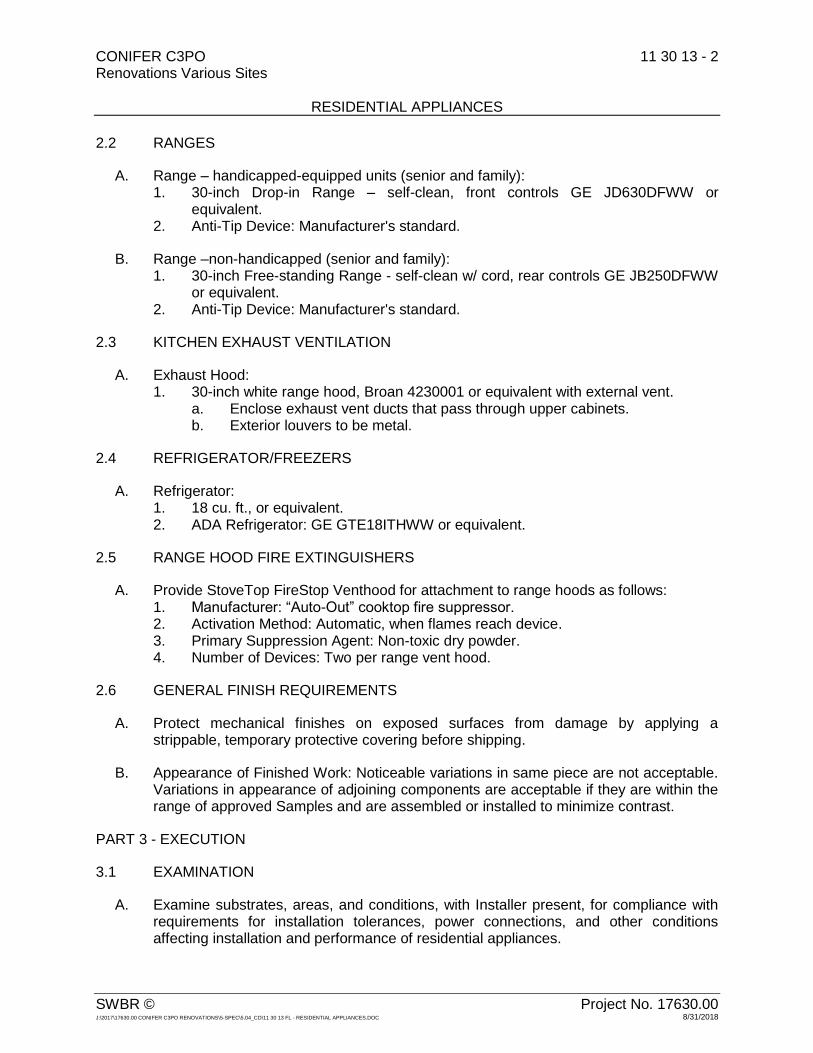
CONIFER C3PO 11 30 13 - 2 Renovations Various Sites RESIDENTIAL APPLIANCES
SWBR © Project No. 17630.00 J:\2017\17630.00 CONIFER C3PO RENOVATIONS\5-SPEC\5.04_CD\11 30 13 FL - RESIDENTIAL APPLIANCES.DOC 8/31/2018
2.2 RANGES
A. Range – handicapped-equipped units (senior and family): 1. 30-inch Drop-in Range – self-clean, front controls GE JD630DFWW or
equivalent. 2. Anti-Tip Device: Manufacturer's standard.
B. Range –non-handicapped (senior and family): 1. 30-inch Free-standing Range - self-clean w/ cord, rear controls GE JB250DFWW
or equivalent. 2. Anti-Tip Device: Manufacturer's standard.
2.3 KITCHEN EXHAUST VENTILATION
A. Exhaust Hood: 1. 30-inch white range hood, Broan 4230001 or equivalent with external vent.
a. Enclose exhaust vent ducts that pass through upper cabinets. b. Exterior louvers to be metal.
2.4 REFRIGERATOR/FREEZERS
A. Refrigerator: 1. 18 cu. ft., or equivalent. 2. ADA Refrigerator: GE GTE18ITHWW or equivalent.
2.5 RANGE HOOD FIRE EXTINGUISHERS
A. Provide StoveTop FireStop Venthood for attachment to range hoods as follows: 1. Manufacturer: “Auto-Out” cooktop fire suppressor. 2. Activation Method: Automatic, when flames reach device. 3. Primary Suppression Agent: Non-toxic dry powder. 4. Number of Devices: Two per range vent hood.
2.6 GENERAL FINISH REQUIREMENTS
A. Protect mechanical finishes on exposed surfaces from damage by applying a strippable, temporary protective covering before shipping.
B. Appearance of Finished Work: Noticeable variations in same piece are not acceptable. Variations in appearance of adjoining components are acceptable if they are within the range of approved Samples and are assembled or installed to minimize contrast.
PART 3 - EXECUTION
3.1 EXAMINATION
A. Examine substrates, areas, and conditions, with Installer present, for compliance with requirements for installation tolerances, power connections, and other conditions affecting installation and performance of residential appliances.

CONIFER C3PO 11 30 13 - 3 Renovations Various Sites RESIDENTIAL APPLIANCES
SWBR © Project No. 17630.00 J:\2017\17630.00 CONIFER C3PO RENOVATIONS\5-SPEC\5.04_CD\11 30 13 FL - RESIDENTIAL APPLIANCES.DOC 8/31/2018
B. Examine roughing-in for piping systems to verify actual locations of piping connections before appliance installation.
C. Examine walls, ceilings, and roofs for suitable conditions where overhead exhaust hoods will be installed.
D. Prepare written report, endorsed by Installer, listing conditions detrimental to performance of the Work.
E. Proceed with installation only after unsatisfactory conditions have been corrected.
3.2 INSTALLATION
A. Install appliances according to manufacturer's written instructions.
B. Built-in Equipment: Securely anchor units to supporting cabinets or countertops with concealed fasteners. Verify that clearances are adequate for proper functioning and that rough openings are completely concealed.
C. Freestanding Equipment: Place units in final locations after finishes have been completed in each area. Verify that clearances are adequate to properly operate equipment.
D. Range Anti-Tip Device: Install at each range according to manufacturer's written instructions.
3.3 DEMONSTRATION
A. Engage a factory-authorized service representative to train Owner's maintenance personnel to adjust, operate, and maintain residential appliances.
END OF SECTION 11 30 13


CONIFER C3PO 12 21 13 - 1 Renovations Various Sites HORIZONTAL LOUVER BLINDS
SWBR © Project No. 17630.00 J:\2017\17630.00 Conifer C3PO Renovations\5-Spec\5.04_CD\12 21 13 FL - Horizontal Louver Blinds.doc 08/31/2018
SECTION 12 21 13 - HORIZONTAL LOUVER BLINDS
PART 1 - GENERAL
1.1 RELATED DOCUMENTS
A. Drawings and general provisions of the Contract, including General and Supplementary Conditions and Division 01 Specification Sections, apply to this Section.
1.2 SUMMARY
A. Section Includes: 1. Horizontal louver blinds with polymer slats.
1.3 ACTION SUBMITTALS
A. Product Data: For each type of product.
B. Shop Drawings: For horizontal louver blinds, include fabrication and installation details.
C. Samples for Initial Selection: For each type and color of horizontal louver blind. 1. Include Samples of accessories involving color selection.
D. Samples for Verification: For each type and color of horizontal louver blind indicated. 1. Horizontal Louver Blind: Full-size unit, not less than 16 inches wide by 24 inches
long. 2. Valance: Full-size unit, not less than 12 inches wide.
E. Product Schedule: For horizontal louver blinds. Use same designations indicated on Drawings.
1.4 INFORMATIONAL SUBMITTALS
A. Product Test Reports: For horizontal louver blinds with polymer slats that have been tested for compliance with NFPA 701, for tests performed by a qualified testing agency.
1.5 CLOSEOUT SUBMITTALS
A. Maintenance Data: For horizontal louver blinds to include in maintenance manuals.
1.6 QUALITY ASSURANCE
A. Mockups: Build mockups to verify selections made under Sample submittals, to demonstrate aesthetic effects, and to set quality standards for fabrication and installation. 1. Approval of mockups does not constitute approval of deviations from the
Contract Documents contained in mockups unless Architect specifically approves such deviations in writing.
2. Subject to compliance with requirements, approved mockups may become part of the completed Work if undisturbed at time of Substantial Completion.

CONIFER C3PO 12 21 13 - 2 Renovations Various Sites HORIZONTAL LOUVER BLINDS
SWBR © Project No. 17630.00 J:\2017\17630.00 Conifer C3PO Renovations\5-Spec\5.04_CD\12 21 13 FL - Horizontal Louver Blinds.doc 08/31/2018
1.7 DELIVERY, STORAGE, AND HANDLING
A. Deliver horizontal louver blinds in factory packages, marked with manufacturer, product name, and location of installation using same designations indicated on Drawings.
1.8 FIELD CONDITIONS
A. Environmental Limitations: Do not install horizontal louver blinds until construction and wet-work and finish work in spaces, including painting, is complete and dry and ambient temperature and humidity conditions are maintained at the levels indicated for Project when occupied for its intended use.
B. Field Measurements: Where horizontal louver blinds are indicated to fit to other construction, verify dimensions of other construction by field measurements before fabrication and indicate measurements on Shop Drawings. Allow clearances for operating hardware of operable glazed units through entire operating range. Notify Architect of installation conditions that vary from Drawings. Coordinate fabrication schedule with construction progress to avoid delaying the Work.
PART 2 - PRODUCTS
2.1 MANUFACTURERS
A. Source Limitations: Obtain horizontal louver blinds from single source from single manufacturer.
2.2 HORIZONTAL LOUVER BLINDS, POLYMER SLATS
A. Product/Manufactuer: 1. Springs Window Fashions; SWF Contract.
B. Flame-Resistance Rating: Comply with NFPA 701; testing by a qualified testing agency. Identify products with appropriate markings of applicable testing agency.
C. Slats: Polymers that are lead free, UV stabilized, integrally colored, opaque, and will not crack or yellow; antistatic, dust-repellent treated. 1. Formulation: Permanently flexible, extruded PVC. 2. Width: 2 inches. 3. Thickness: 0.045 inch. 4. Spacing: Manufacturer's standard. 5. Profile: Crowned.
D. Headrail: Formed steel or extruded aluminum; long edges returned or rolled. Headrail fully encloses operating mechanisms on three sides and ends. 1. Capacity: One blind(s) per headrail unless otherwise indicated. 2. Manual Lift Mechanism:
a. Lift-Cord Lock: Variable; stops lift cord at user-selected position within full operating range.
b. Operator: Extension of lift cord(s) through lift-cord lock mechanism to form cord pull.

CONIFER C3PO 12 21 13 - 3 Renovations Various Sites HORIZONTAL LOUVER BLINDS
SWBR © Project No. 17630.00 J:\2017\17630.00 Conifer C3PO Renovations\5-Spec\5.04_CD\12 21 13 FL - Horizontal Louver Blinds.doc 08/31/2018
3. Manual Tilt Mechanism: Enclosed worm-gear mechanism and linkage rod that adjusts ladders. a. Tilt: Full. b. Operator: Clear-plastic wand. c. Over-Rotation Protection: Manufacturer's detachable operator or slip clutch
to prevent over rotation of gear. 4. Manual Lift-Operator and Tilt-Operator Lengths: Full length of blind when blind is
fully closed. 5. Manual Lift-Operator and Tilt-Operator Locations: Manufacturer's standard
unless otherwise indicated.
E. Bottom Rail: Secures and protects ends of ladders and lift cords. 1. Type: Manufacturer's standard.
F. Lift Cord: Manufacturer's standard braided cord.
G. Ladders: Evenly spaced across headrail at spacing that prevents long-term slat sag. 1. Type: Braided cord.
H. Valance: Manufacturer's standard.
I. Mounting Brackets: With spacers and shims required for blind placement and alignment indicated. 1. Type: Overhead. 2. Intermediate Support: Provide intermediate support brackets to produce support
spacing recommended by blind manufacturer for weight and size of blind.
J. Colors, Textures, Patterns, and Gloss: 1. Slats: As selected by Architect from manufacturer's full range. 2. Components: Provide rails, cords, ladders, and materials exposed to view
matching or coordinating with slat color unless otherwise indicated.
2.3 HORIZONTAL LOUVER BLIND FABRICATION
A. Product Safety Standard: Fabricate horizontal louver blinds to comply with WCMA A 100.1 including requirements for corded, flexible, looped devices; lead content of components; and warning labels.
B. Unit Sizes: Fabricate units in sizes to fill window and other openings as follows, measured at 74 deg F: 1. Between (Inside) Jamb Installation: Width equal to jamb-to-jamb dimension of
opening in which blind is installed less 1/4 inch per side or 1/2 inch total, plus or minus 1/8 inch. Length equal to head-to-sill dimension of opening in which blind is installed less 1/4 inch, plus or minus 1/8 inch.
2. Outside of Jamb Installation: Width and length as indicated, with terminations between blinds of end-to-end installations at centerlines of mullion or other defined vertical separations between openings.
C. Concealed Components: Noncorrodible or corrosion-resistant-coated materials. 1. Lift-and-Tilt Mechanisms: With permanently lubricated moving parts.

CONIFER C3PO 12 21 13 - 4 Renovations Various Sites HORIZONTAL LOUVER BLINDS
SWBR © Project No. 17630.00 J:\2017\17630.00 Conifer C3PO Renovations\5-Spec\5.04_CD\12 21 13 FL - Horizontal Louver Blinds.doc 08/31/2018
D. Mounting and Intermediate Brackets: Designed for removal and reinstallation of blind without damaging blind and adjacent surfaces, for supporting blind components, and for bracket positions and blind placement indicated.
E. Installation Fasteners: No fewer than two fasteners per bracket, fabricated from metal noncorrosive to brackets and adjoining construction; type designed for securing to supporting substrate; and supporting blinds and accessories under conditions of normal use.
F. Color-Coated Finish: 1. Metal: For components exposed to view, apply manufacturer's standard baked
finish complying with manufacturer's written instructions for surface preparation including pretreatment, application, baking, and minimum dry film thickness.
PART 3 - EXECUTION
3.1 EXAMINATION
A. Examine substrates, areas, and conditions, with Installer present, for compliance with requirements for installation tolerances, operational clearances, and other conditions affecting performance of the Work.
B. Proceed with installation only after unsatisfactory conditions have been corrected.
3.2 INSTALLATION
A. Install horizontal louver blinds level and plumb, aligned and centered on openings, and aligned with adjacent units according to manufacturer's written instructions. 1. Locate so exterior slat edges are not closer than 2 inches from interior faces of
glass and not closer than 1-1/2 inches from interior faces of glazing frames through full operating ranges of blinds.
2. Install mounting and intermediate brackets to prevent deflection of headrails. 3. Install with clearances that prevent interference with adjacent blinds, adjacent
construction, and operating hardware of glazed openings, other window treatments, and similar building components and furnishings.
3.3 ADJUSTING
A. Adjust horizontal louver blinds to operate free of binding or malfunction through full operating ranges.
3.4 CLEANING AND PROTECTION
A. Clean horizontal louver blind surfaces after installation according to manufacturer's written instructions.
B. Provide final protection and maintain conditions in a manner acceptable to manufacturer and Installer that ensures that horizontal louver blinds are without damage or deterioration at time of Substantial Completion.
CONIFER C3PO 12 21 13 - 5 Renovations Various Sites HORIZONTAL LOUVER BLINDS
SWBR © Project No. 17630.00 J:\2017\17630.00 Conifer C3PO Renovations\5-Spec\5.04_CD\12 21 13 FL - Horizontal Louver Blinds.doc 08/31/2018
C. Replace damaged horizontal louver blinds that cannot be repaired in a manner approved by Architect before time of Substantial Completion.
END OF SECTION 12 21 13


CONIFER C3PO 12 35 30 - 1 Renovations Various Sites RESIDENTIAL CASEWORK
SWBR © Project No. 17630.00 J:\2017\17630.00 Conifer C3PO Renovations\5-Spec\5.04_CD\12 35 30 FL - Residential Casework.doc 08/31/2018
SECTION 12 35 30 - RESIDENTIAL CASEWORK
PART 1 - GENERAL
1.1 RELATED DOCUMENTS
A. Drawings and general provisions of the Contract, including General and Supplementary Conditions and Division 01 Specification Sections, apply to this Section.
1.2 SUMMARY
A. Section includes kitchen and vanity cabinets.
1.3 DEFINITIONS
A. Concealed Surfaces of Casework: Surfaces not usually visible after installation, including sleepers, web frames, dust panels, bottoms of drawers, and ends of casework installed directly against and completely concealed by walls or other casework, and tops of wall cabinets and utility cabinets.
B. Exposed Surfaces of Casework: Surfaces visible when doors and drawers are closed, including visible surfaces in open cabinets or behind glass doors.
C. Semiexposed Surfaces of Casework: Surfaces behind opaque doors or drawer fronts, including interior faces of doors, interiors and sides of drawers, and bottoms of wall cabinets.
1.4 COORDINATION
A. Coordinate layout and installation of blocking and reinforcement in partitions for support of casework.
1.5 ACTION SUBMITTALS
A. Product Data: For each type of product. 1. Include construction details, material descriptions, dimensions of individual
components, and profiles and finishes for casework. 2. Include rated capacities, operating characteristics, profiles, and finishes for
hardware.
B. Shop Drawings: For residential casework. 1. Include plans, elevations, details, and attachments to other work. 2. Show materials, finishes, filler panels, and hardware. 3. Indicate manufacturer's catalog numbers for casework.
C. Samples for Initial Selection: For casework and hardware finishes.

CONIFER C3PO 12 35 30 - 2 Renovations Various Sites RESIDENTIAL CASEWORK
SWBR © Project No. 17630.00 J:\2017\17630.00 Conifer C3PO Renovations\5-Spec\5.04_CD\12 35 30 FL - Residential Casework.doc 08/31/2018
D. Samples for Verification: For the following: 1. Casework Finishes: 8-by-10-inch Samples for each type of casework finish. 2. Hardware: One full-size Sample of each type of exposed hardware in each finish
required. 3. Base Cabinet: One full-size, 16-inch-wide, finished base cabinet complete with
hardware, doors, and drawers but without countertop. 4. Wall Cabinet: One full-size, 12-inch-wide, finished wall cabinet complete with
hardware, doors, and adjustable shelves. 5. Full-Size Samples: Maintain at Project site during construction in an undisturbed
condition as a standard for judging the completed Work. Unless otherwise indicated, approved sample units may become part of the completed Work if in undisturbed condition at time of Substantial Completion. Notify Architect of their exact locations.
1.6 INFORMATIONAL SUBMITTALS
A. Qualification Data: For manufacturer.
B. Product Certificates: For casework.
1.7 FIELD CONDITIONS
A. Environmental Limitations: Do not deliver or install casework until building is enclosed, wet-work is complete, and HVAC system is operating and maintaining temperature and relative humidity at levels planned for building occupants during the remainder of the construction period.
B. Field Measurements: Where casework is indicated to fit to existing construction, verify dimensions of existing construction by field measurements before fabrication and indicate measurements on Shop Drawings. Provide fillers and scribes to allow for trimming and fitting.
C. Locate concealed framing, blocking, and reinforcements that support casework by field measurements before enclosing them, and indicate measurements on Shop Drawings.
PART 2 - PRODUCTS
2.1 CABINETS
A. Product/Manufacturers: Subject to compliance with requirements, provide products by the following: 1. CNC Cabinetry Country Collection, s; CNC Associates, Inc.
B. Quality Standard: Provide cabinets that comply with KCMA A161.1. 1. KCMA Certification: Provide cabinets with KCMA's "Certified Cabinet" seal
affixed in a semiexposed location of each unit and showing compliance with KCMA A161.1.

CONIFER C3PO 12 35 30 - 3 Renovations Various Sites RESIDENTIAL CASEWORK
SWBR © Project No. 17630.00 J:\2017\17630.00 Conifer C3PO Renovations\5-Spec\5.04_CD\12 35 30 FL - Residential Casework.doc 08/31/2018
C. Door and Drawer Face Style: Partial overlay; faces cover cabinet fronts.
D. Factory Finishing: Finish cabinets at factory.
2.2 WALL CABINETS
A. Wall Back: ¼-inch substrate, with 3-inch plywood surrounding frame, all plywood material. Rabbeted and stapled into cabinet sides, screwed into top and bottom.
B. Wall End Panel: Wall End Panels, top and bottom ½-inch plywood substrate, with light maple woodgrain laminate interior. Matching wood veneer exterior.
C. Wall Frame: ¾-inch thick, 1-1/2-inch wide, kiln-dried solid hard-wood. Assembled with glue and nails, under clamp pressure, which ensures squareness.
D. Shelves: ¾-inch thick, plywood; fully adjustable.
E. Hinges: Heavy duty steel concealed hinge, six-way adjustable.
2.3 BASE CABINET
A. Base Back: 1/4-inch substrate, with 3-inch plywood surrounding frame, all plywood material. Rabbeted and stapled into cabinet sides, screwed into top and bottom.
B. Shelves: ¾-inch thick, plywood; fully adjustable. (12" deep).
C. Base End Panel: ½-inch plywood substrate, with light maple woodgrain laminate interior. Matching wood veneer exterior.
D. Toe Kick: 4-1/2-inch Toe kick with 3-inch inset.
E. Base Frame: ¾-inch thick, 1-1/2-inch wide, kiln-dried solid hard-wood. Assembled with glue and nails, under clamp pressure, which ensures squareness.
F. Glides: High quality epoxy coated steel under mounted glides.
G. Drawers: 3/4-inch solid wood Dovetail sides 3/8-inch thick bottom.
H. Hinges: Heavy duty steel concealed hinge, six-way adjustable.
2.4 CABINET MATERIALS
A. Hardwood Lumber: Kiln dried to 7 percent moisture content.
B. Softwood Lumber: Kiln dried to 10 percent moisture content.
C. Hardwood Plywood: HPVA HP-1.

CONIFER C3PO 12 35 30 - 4 Renovations Various Sites RESIDENTIAL CASEWORK
SWBR © Project No. 17630.00 J:\2017\17630.00 Conifer C3PO Renovations\5-Spec\5.04_CD\12 35 30 FL - Residential Casework.doc 08/31/2018
D. Exposed Materials: 1. Exposed Wood Species: Birch.
a. Select materials for compatible color and grain. Do not use two adjacent exposed surfaces that are noticeably dissimilar in color, grain, figure, or natural character markings.
b. Staining and Finish: As selected by Architect from manufacturer's full range.
2. Solid Wood: Clear hardwood lumber of species indicated, free of defects. 3. Plywood: Hardwood plywood with face veneer of species indicated, with Grade A
faces and Grade C backs of same species as faces. a. Edge band exposed edges with veneer edging of same species as face
veneer.
E. Semiexposed Materials: Unless otherwise indicated, provide the following: 1. Solid Wood: Sound hardwood lumber, selected to eliminate appearance defects.
Same species as exposed surfaces or stained to be compatible with exposed surfaces.
2. Plywood: Hardwood plywood with Grade C faces and not less than Grade 3 backs of same species as faces. Face veneers of same species as exposed surfaces or stained to be compatible with exposed surfaces.
F. Concealed Materials: Solid wood or plywood, of any hardwood or softwood species, with no defects affecting strength or utility; particleboard; MDF; or hardboard.
2.5 CABINET HARDWARE
A. General: Manufacturer's standard units complying with BHMA A156.9, of type, size, style, material, and finish as selected by Architect from manufacturer's full range.
B. Pulls: [Surface-mounted decorative pulls] [Back-mounted decorative pulls] [Back-mounted decorative pulls with backing plates] [Wire pulls] [Back-mounted knobs] [Surface-mounted porcelain knobs].
C. Hinges: Fully concealed European-style, soft-closing hinges, 6 way adjustable hinges.
D. Drawer Guides: Ball bearing stainless steel, soft-close, full extension, concealed undermount metal glides, 150 pound load capacity.
E. Door and Drawer Bumpers: Self-adhering, clear silicone rubber. 1. Doors: Provide one bumper at top and bottom of closing edge of each swinging
door. 2. Drawers: Provide one bumper on back side of drawer front at each corner.
PART 3 - EXECUTION
3.1 EXAMINATION
A. Examine areas, with Installer present, for compliance with requirements for installation tolerances, location of framing and reinforcements, and other conditions affecting performance of casework.

CONIFER C3PO 12 35 30 - 5 Renovations Various Sites RESIDENTIAL CASEWORK
SWBR © Project No. 17630.00 J:\2017\17630.00 Conifer C3PO Renovations\5-Spec\5.04_CD\12 35 30 FL - Residential Casework.doc 08/31/2018
B. Proceed with installation only after unsatisfactory conditions have been corrected.
3.2 INSTALLATION
A. Install casework with no variations in adjoining surfaces; use concealed shims. Where casework abuts other finished work, scribe and cut for accurate fit. Provide filler strips, scribe strips, and moldings in finish to match casework.
B. Install casework without distortion so doors and drawers fit the openings, are aligned, and are uniformly spaced. Complete installation of hardware and accessories as indicated.
C. Install casework level and plumb to a tolerance of 1/8 inch in 8 feet.
D. Fasten casework to adjacent units and to backing. 1. Fasten wall cabinets through back, near top and bottom, and at ends not more
than 16 inches o.c. a. Fasteners: No. 10 wafer-head screws sized for not less than 1-1/2-inch
penetration into wood framing, blocking, or hanging strips.
3.3 ADJUSTING AND CLEANING
A. Adjust hardware so doors and drawers are centered in openings and operate smoothly without warp or bind. Lubricate operating hardware as recommended by manufacturer.
B. Clean casework on exposed and semiexposed surfaces. Touch up as required to restore damaged or soiled areas to match original factory finish, as approved by Architect.
END OF SECTION 12 35 30


CONIFER C3PO 12 36 23.13 - 1 Renovations Various Sites PLASTIC-LAMINATE-CLAD COUNTERTOPS
SWBR © Project No. 17630.00 J:\2017\17630.00 Conifer C3PO Renovations\5-Spec\5.04_CD\12 36 23_13 FL - Plastic-Laminate-Clad Countertops.doc 08/31/2018
SECTION 12 36 23.13 - PLASTIC-LAMINATE-CLAD COUNTERTOPS
PART 1 - GENERAL
1.1 RELATED DOCUMENTS
A. Drawings and general provisions of the Contract, including General and Supplementary Conditions and Division 01 Specification Sections, apply to this Section.
1.2 SUMMARY
A. Section includes plastic-laminate-clad countertops.
1.3 ACTION SUBMITTALS
A. Product Data: For each type of product. 1. Include data for fire-retardant treatment from chemical-treatment manufacturer
and certification by treating plant that treated materials comply with requirements.
B. Shop Drawings: For plastic-laminate-clad countertops. 1. Include plans, sections, details, and attachments to other work. Detail fabrication
and installation, including field joints. 2. Show locations and sizes of cutouts and holes for items installed in plastic-
laminate-clad countertops.
C. Samples for Initial Selection: For plastic laminates.
D. Samples for Verification: As follows: 1. Plastic Laminates: For each type, color, pattern, and surface finish required, 8 by
10 inches in size. 2. Fabrication Sample: For each type and profile of countertop required, provide
one sample applied to core material with specified edge material applied to one edge.
1.4 INFORMATIONAL SUBMITTALS
A. Qualification Data: For fabricator.
1.5 QUALITY ASSURANCE
A. Fabricator Qualifications: Shop that employs skilled workers who custom fabricate products similar to those required for this Project and whose products have a record of successful in-service performance.
1.6 DELIVERY, STORAGE, AND HANDLING
A. Deliver countertops only after casework and supports on which they will be installed have been completed in installation areas.

CONIFER C3PO 12 36 23.13 - 2 Renovations Various Sites PLASTIC-LAMINATE-CLAD COUNTERTOPS
SWBR © Project No. 17630.00 J:\2017\17630.00 Conifer C3PO Renovations\5-Spec\5.04_CD\12 36 23_13 FL - Plastic-Laminate-Clad Countertops.doc 08/31/2018
B. Store countertops in areas where environmental conditions comply with requirements specified in "Field Conditions" Article.
C. Keep surfaces of countertops covered with protective covering during handling and installation.
1.7 FIELD CONDITIONS
A. Environmental Limitations: Do not deliver or install countertops until building is enclosed, wet-work is complete, and HVAC system is operating and maintaining temperature and relative humidity at levels planned for building occupants during the remainder of the construction period.
B. Field Measurements: Where countertops are indicated to fit to other construction, verify dimensions of other construction by field measurements before fabrication and indicate measurements on Shop Drawings. Coordinate fabrication schedule with construction progress to avoid delaying the Work.
C. Established Dimensions: Where countertops are indicated to fit to other construction, establish dimensions for areas where countertops are to fit. Provide allowance for trimming at site, and coordinate construction to ensure that actual dimensions correspond to established dimensions.
PART 2 - PRODUCTS
2.1 PLASTIC-LAMINATE-CLAD COUNTERTOPS
A. Quality Standard: Unless otherwise indicated, comply with the "Architectural Woodwork Standards" for grades of plastic-laminate-clad countertops indicated for construction, finishes, installation, and other requirements. 1. The Contract Documents contain requirements that are more stringent than the
referenced quality standard. Comply with requirements of Contract Documents in addition to those of the referenced quality standard.
B. Grade: Custom.
C. High-Pressure Decorative Laminate: NEMA LD 3, Grade HGS and Grade HGP.
D. Colors, Patterns, and Finishes: Provide materials and products that result in colors and textures of exposed laminate surfaces complying with the following requirements: 1. As indicated by manufacturer's designations.
E. Edge Treatment: 3-mm PVC edging.
F. Core Material: Exterior-grade plywood.
G. Core Material at Sinks: Exterior-grade plywood.

CONIFER C3PO 12 36 23.13 - 3 Renovations Various Sites PLASTIC-LAMINATE-CLAD COUNTERTOPS
SWBR © Project No. 17630.00 J:\2017\17630.00 Conifer C3PO Renovations\5-Spec\5.04_CD\12 36 23_13 FL - Plastic-Laminate-Clad Countertops.doc 08/31/2018
H. Core Thickness: 3/4 inch. 1. Build up countertop thickness to 1-1/2 inches at front, back, and ends with
additional layers of core material laminated to top.
I. Backer Sheet: Provide plastic-laminate backer sheet, NEMA LD 3, Grade BKL, on underside of countertop substrate.
2.2 WOOD MATERIALS
A. Wood Products: Provide materials that comply with requirements of referenced quality standard unless otherwise indicated. 1. Wood Moisture Content: 5 to 10 percent.
B. Composite Wood Products: Provide materials that comply with requirements of referenced quality standard for each type of countertop and quality grade specified unless otherwise indicated. 1. Softwood Plywood: DOC PS 1.
2.3 MISCELLANEOUS MATERIALS
A. Installation Adhesive: 1. Adhesives shall have a VOC content of 70 g/L or less.
2.4 FABRICATION
A. Fabricate countertops to dimensions, profiles, and details indicated. Provide front and end overhang of 1 inch over base cabinets. Ease edges to radius indicated for the following:
B. Complete fabrication, including assembly, to maximum extent possible before shipment to Project site. Disassemble components only as necessary for shipment and installation. Where necessary for fitting at site, provide ample allowance for scribing, trimming, and fitting.
C. Shop cut openings to maximum extent possible to receive appliances, plumbing fixtures, electrical work, and similar items. Locate openings accurately, and use templates or roughing-in diagrams to produce accurately sized and shaped openings. Sand edges of cutouts to remove splinters and burrs. 1. Seal edges of cutouts by saturating with varnish.
PART 3 - EXECUTION
3.1 PREPARATION
A. Before installation, condition countertops to average prevailing humidity conditions in installation areas.
B. Before installing countertops, examine shop-fabricated work for completion and complete work as required, including removal of packing.

CONIFER C3PO 12 36 23.13 - 4 Renovations Various Sites PLASTIC-LAMINATE-CLAD COUNTERTOPS
SWBR © Project No. 17630.00 J:\2017\17630.00 Conifer C3PO Renovations\5-Spec\5.04_CD\12 36 23_13 FL - Plastic-Laminate-Clad Countertops.doc 08/31/2018
3.2 INSTALLATION
A. Grade: Install countertops to comply with same grade as item to be installed.
B. Assemble countertops and complete fabrication at Project site to the extent that it was not completed in the shop. 1. Provide cutouts for appliances, plumbing fixtures, electrical work, and similar
items. Locate openings accurately, and use templates or roughing-in diagrams to produce accurately sized and shaped openings. Sand edges of cutouts to remove splinters and burrs.
2. Seal edges of cutouts by saturating with varnish.
C. Field Jointing: Where possible, make in the same manner as shop jointing, using dowels, splines, adhesives, and fasteners recommended by manufacturer. Prepare edges to be joined in shop so Project-site processing of top and edge surfaces is not required. Locate field joints where shown on Shop Drawings. 1. Secure field joints in countertops with concealed clamping devices located within
6 inches of front and back edges and at intervals not exceeding 24 inches. Tighten according to manufacturer's written instructions to exert a constant, heavy-clamping pressure at joints.
D. Scribe and cut countertops to fit adjoining work, refinish cut surfaces, and repair damaged finish at cuts.
E. Countertop Installation: Anchor securely by screwing through corner blocks of base cabinets or other supports into underside of countertop. 1. Install countertops level and true in line. Use concealed shims as required to
maintain not more than a 1/8-inch-in-96-inchesvariation from a straight, level plane.
2. Secure backsplashes to tops with concealed metal brackets at 16 inches o.c. and to walls with adhesive.
3. Seal joints between countertop and backsplash, if any, and joints where countertop and backsplash abut walls with mildew-resistant silicone sealant or another permanently elastic sealing compound recommended by countertop material manufacturer.
3.3 ADJUSTING AND CLEANING
A. Repair damaged and defective countertops, where possible, to eliminate functional and visual defects. Where not possible to repair, replace countertops. Adjust joinery for uniform appearance.
B. Clean countertops on exposed and semiexposed surfaces.
C. Protection: Provide Kraft paper or other suitable covering over countertop surfaces, taped to underside of countertop at a minimum of 48 inches o.c. Remove protection at Substantial Completion.
END OF SECTION 12 36 23.13

CONIFER C3PO 12 36 61.13 - 1 Renovations Various Sites CULTURED MARBLE COUNTERTOPS
SWBR © Project No. 17630.00 J:\2017\17630.00 Conifer C3PO Renovations\5-Spec\5.04_CD\12 36 61_13 FL - Cultured Marble Countertops.doc 08/31/2018
SECTION 12 36 61.13 - CULTURED MARBLE COUNTERTOPS
PART 1 - GENERAL
1.1 RELATED DOCUMENTS
A. Drawings and general provisions of the Contract, including General and Supplementary Conditions and Division 01 Specification Sections, apply to this Section.
1.2 SUMMARY
A. Section Includes: 1. Cultured marble countertops. 2. Integral sinks. 3. Integral backsplashes. 4. Integral end splashes.
1.3 ACTION SUBMITTALS
A. Product Data: For countertop materials.
B. Shop Drawings: For countertops. Show materials, finishes, edge and backsplash profiles, integral sinks, and methods of joining.
C. Samples for Initial Selection: For each type of material exposed to view.
D. Samples for Verification: For the following products: 1. Countertop material, 6 inches square.
1.4 COORDINATION
A. Coordinate locations of utilities that will penetrate countertops or backsplashes.
PART 2 - PRODUCTS
2.1 MANUFACTURERS
A. Manufacturers: Subject to compliance with requirements, provide products by the following: 1. Rynone Manufacturing Corp.
2.2 CULTURED MARBLE COUNTERTOPS
A. Cultured Marble: Gel-coated solid fabrication of filled plastic resin complying with CSA B45.5/IAPMO Z124. 1. Colors and Patterns: As selected by Architect from manufacturer's full range.

CONIFER C3PO 12 36 61.13 - 2 Renovations Various Sites CULTURED MARBLE COUNTERTOPS
SWBR © Project No. 17630.00 J:\2017\17630.00 Conifer C3PO Renovations\5-Spec\5.04_CD\12 36 61_13 FL - Cultured Marble Countertops.doc 08/31/2018
B. Configuration: One-piece units with integral sink bowls and backsplashes unless otherwise indicated, not less than 1/2 inch thick. 1. Front: Waterfall edge. 2. Backsplash: Straight, with 3/8-inch radius cove and slightly eased at top. 3. Endsplash: Matching backsplash.
C. Fabrication: Fabricate tops in one piece with integral sink bowls and backsplashes unless otherwise indicated. 1. Provide sink with rear discharge overflow drain.
2.3 INSTALLATION MATERIALS
A. Adhesive: Product recommended by cultured marble manufacturer.
B. Sealant for Countertops: Comply with applicable requirements in Section 07 92 00 "Joint Sealants."
PART 3 - EXECUTION
3.1 INSTALLATION
A. Install countertops level to a tolerance of 1/8 inch in 8 feet.
B. Fasten countertops by screwing through corner blocks of base units into underside of countertop. Predrill holes for screws as recommended by manufacturer. 1. Install end splashes to comply with manufacturer's written instructions.
C. Install aprons to backing and countertops with adhesive. Fasten by screwing through backing. Predrill holes for screws as recommended by manufacturer.
D. Apply sealant to gaps at walls; comply with Section 07 92 00 "Joint Sealants." Remove temporary shims before applying sealant.
END OF SECTION 12 36 61.13

CONIFER C3PO 22 00 10 - 1 Renovations Various Sites BASIC PLUMBING REQUIREMENTS
TURNER ENGINEERING, PC Project No. 18118 8/31/2018
SECTION 22 00 10 - BASIC PLUMBING REQUIREMENTS
PART 1 - GENERAL 1.1 RELATED DOCUMENTS
A. All drawings and general provisions of Contract, including all General and Supplementary Conditions, Division 01 Specification Sections, and Instructions to Bidders apply to this section and all other sections of Division 22.
1.2 ELECTRONIC DRAWING FILES
A. Electronic CAD Floor Plan Backgrounds
1. Turner Engineering, PC cannot provide architectural floor plan backgrounds. Contact the project architect to obtain CAD files of the building floor plans.
B. Electronic Engineering CAD Files
1. If engineering CAD files are required, Turner Engineering, PC can provide these files at a cost of $50 per drawing. These files will be provided in .dwg or .dgn format, as requested. Title blocks and all reference to Turner Engineering, PC, the architect, or other design professionals will be removed from these electronic files.
2. If the engineering REVIT model is required, Turner Engineering, PC can provide this file at a cost of $50. The REVIT model will be provide in our current version of REVIT Turner Engineering is using. Title blocks and all reference to Turner Engineering, PC, the architect, or other design professionals shall be removed from the electronic REVIT model.
3. To request these files, go to www.turnerengineering.com. There is an electronic request form under the “Contractor Requests” heading. Fill out this form and submit the form electronically. Send a check made out to “Turner Engineering, PC” for the proper amount. When we have received the completed form and the check, we will e-mail the electronic files to the e-mail address indicated on the form.
4. Turner Engineering, PC does not assume any responsibility for the electronic files, nor for the accuracy of the floor plans.
C. Electronic Engineering Portable Document Files (pdf)
1. If Portable Document Files (.pdf) are required, Turner Engineering, PC can provide these files at a cost of $50 per drawing.
2. To request these files, please go to www.turnerengineering.com. There is an electronic request form under the “Contractor Requests” heading. Fill out this form and submit the form electronically. Send a check made out to “Turner Engineering, PC” for the proper amount. When we have received the completed form and the check, we will e-mail the electronic files to the e-mail address indicated on the form.

CONIFER C3PO 22 00 10 - 2 Renovations Various Sites BASIC PLUMBING REQUIREMENTS
TURNER ENGINEERING, PC Project No. 18118 8/31/2018
3. Turner Engineering, PC does not assume any responsibility for the electronic files, nor for the accuracy of the floor plans.
1.3 SCOPE OF WORK
A. Include in bid all labor, materials, tools, plant, transportation, excavation, equipment, insurance, temporary protection, permits, taxes and all necessary and related items required to provide complete and operational systems shown and described.
B. References to codes and Standards called for in the Contract Documents mean the
latest edition, amendment and revisions to the codes and standards in effect on the date of these Contract Documents.
C. Minimum composition requirements and/or installation methods for the following
materials and work are included in this section:
1. Miscellaneous Supports 2. Access Doors and Panels 3. Fire Stopping 4. Flashing and Sealing 5. Cutting and Patching
D. Contract shall include, but not be limited to:
1. Plumbing.
1.4 REGULATIONS AND CODE COMPLIANCE
A. All work and materials shall conform to and be installed, inspected and tested in accordance with the governing rules and regulations of federal, state and local governmental agencies.
B. The following is a list of codes and standards that will apply to this project:
1. 2015 International Building Code 2. 2015 International Mechanical Code 3. 2015 International Plumbing Code 4. 2015 International Fuel Gas Code 5. 2015 International Energy Conservation Code 6. New York State Department of Labor Rules and Regulations 7. New York State Department of Health 8. ASHRAE Standard 62 9. Federal Occupational Safety and Health Administration - OSHA 10. National Life Safety Code, NFPA 101 11. National Electrical Code, NFPA 70 12. Local Codes and Ordinances 13. NEMA Standards 14. Underwriters Laboratory (UL) 15. Factory Mutual and/or Owner’s Insurance Carrier

CONIFER C3PO 22 00 10 - 3 Renovations Various Sites BASIC PLUMBING REQUIREMENTS
TURNER ENGINEERING, PC Project No. 18118 8/31/2018
16. New York Board of Fire Underwriters 17. Local Town Bureau of Buildings and Zoning 18. Combustion Toxicity Amendment to the New York State Uniform Fire Prevention
and Building Code 1.5 LICENSING & PERMITS
A. The Contractor shall hold a license to perform the work as issued by the State of New York.
B. Apply for and obtain all required permits and inspections, include costs for all fees and
charges within bid.
C. Refer to General Conditions of the Contract for additional requirements. 1.6 GLOSSARY
ACI American Concrete Institute ADA Americans with Disabilities Act AGA American Gas Association AGCA Associated General Contractors of America, Inc. AIA American Institute of Architects AISC American Institute of Steel Construction AMCA Air Moving and Conditioning Association ANSI American National Standards Institute ARI Air-Conditioning and Refrigeration Institute ASHRAE American Society of Heating, Refrigeration and Air-Conditioning
Engineers ASME American Society of Mechanical Engineers ASPE American Society of Plumbing Engineers ASTM American Society for Testing Materials AWSC American Welding Society Code AWWA American Water Works Association EIA Electronic Industries Association FCC Federal Communications Commission FM Factory Mutual Insurance Company IEEE Institute of Electrical and Electronics Engineers IRI Industrial Risk Insurers ISO International Standards Organization NEC National Electrical Code NEMA National Electrical Manufacturers' Association NESC National Electrical Safety Code NFPA National Fire Protection Association NYBFU New York Board of Fire Underwriters NYS/DEC New York State Department of Environmental Conservation OSHA Occupational Safety and Health Administration SBI Steel Boiler Institute SMACNA Sheet Metal and Air Conditioning Contractors National Association TIA Telecommunications Industry Association

CONIFER C3PO 22 00 10 - 4 Renovations Various Sites BASIC PLUMBING REQUIREMENTS
TURNER ENGINEERING, PC Project No. 18118 8/31/2018
UFPO Underground Facilities Protective Organization UL Underwriter's Laboratories, Inc.
1.7 DEFINITIONS
Approved / Approval Written permission to use a material or system.
As Called For Materials, equipment including the execution specified/shown in the contract documents.
Code Requirements Minimum requirements.
Concealed Work installed in pipe and duct shafts, chases or recesses, inside walls, above ceilings, in slabs or below grade.
Design Equipment Refer to the article, BASIS OF DESIGN.
Design Make Refer to the article, BASIS OF DESIGN.
Equal or Equivalent Equally acceptable as determined by Owner’s Representative.
Exposed Work not identified as concealed.
Final Acceptance Owner acceptance of the project from Contractor upon certification by Owner's Representative.
Furnish Supply and deliver to installation location.
Furnished by Others Receive delivery at job site or where called for and install.
Inspection Visual observations by Owner's Site Representative.
Install Mount and connect equipment and associated materials ready for use.
Labeled Refers to classification by a standards agency.
Make Refer to the article, BASIS OF DESIGN.
Or Approved Equal Approved equal or equivalent as determined by Owner’s Representative.
Owner’s Representative The Prime Professional
Prime Professional Architect or Engineer having a contract directly with the Owner for professional services.

CONIFER C3PO 22 00 10 - 5 Renovations Various Sites BASIC PLUMBING REQUIREMENTS
TURNER ENGINEERING, PC Project No. 18118 8/31/2018
Provide Furnish, install and connect ready for use.
Relocate Disassemble, disconnect, and transport equipment to new locations, then clean, test, and install ready for use.
Replace Remove and provide new item.
Review A general contractual conformance check of specified products.
Roughing Pipe, duct, conduit, equipment layout and installation.
Satisfactory As specified in contract documents.
Site Representative Construction Manager or Owner's Inspector at the work site.
Refer to General Conditions of the Contract for additional definitions. 1.8 BASIS OF DESIGN
A. The contract documents are prepared on basis of one manufacturer as "design equipment". Other manufacturers are listed as acceptable, and may be submitted. If the Contractor elects to use one of the listed makes other than "design equipment”, submit detailed drawings, indicating proposed installation of equipment. Show maintenance clearances, service removal space required, and other pertinent revisions to the design arrangement. If the submitted equipment is larger than the design make equipment, verify the equipment will physically fit in the space provided, and make all necessary modifications required to install the equipment. Make required changes in the work of other trades, at no increase in any contract. Provide larger electrical feeders, circuit breakers, equipment, additional control devices and other miscellaneous equipment required for proper operation, and assume responsibility for proper location of roughing and connections by other trades. Remove and replace door frames, access doors, walls ceilings or floors required to install other than design make equipment. If revised arrangement submittal is rejected, revise and resubmit specified "design equipment" item which conforms to contract documents.
1.9 INTENT OF DRAWINGS
A. The drawings are diagrammatic, unless detailed dimensioned drawings are included.
Drawings show approximate locations of equipment, and fixtures. Exact locations are subject to the approval of the Owner's Representative.
1.10 QUALITY ASSURANCE
A. Manufacturers of equipment shall be firms regularly and currently engaged in the production of equipment and accessories provided. The design and size of each item of equipment provided for this project needs to have been in satisfactory and efficient operation on at least three (3) installations for not less than three (3) years.

CONIFER C3PO 22 00 10 - 6 Renovations Various Sites BASIC PLUMBING REQUIREMENTS
TURNER ENGINEERING, PC Project No. 18118 8/31/2018
B. Suppliers of equipment must have factory trained and authorized personnel for the service of all equipment provided.
C. Apply and install materials, equipment, and specialties in accordance with
manufacturer’s written instructions. Conflicts between the manufacturer’s instructions and the contract documents shall be referred to the Owner’s Representative for resolution.
D. The contractor shall engage the services of a qualified installer for the installation and
application of joint sealers, flashing, access panels, cutting and patching.
E. All work shall be done in a neat and workmanlike manner. All methods of construction, details of workmanship, that are not specifically described or indicated in the contract documents, shall be subject to the control and approval of the Owner's Representative. Equipment and materials shall be of the quality and manufacture indicated. The equipment specified is based upon the acceptable manufacturers listed. Where "approved equal" is stated, equipment shall be equivalent in every way to that of the equipment specified and subject to approval.
PART 2 - PRODUCTS 2.1 EQUIPMENT AND MATERIAL MINIMUM REQUIREMENTS
A. Provide Materials That Meet the Following Minimum Requirements:
1. Materials shall have a flame spread rating of 25 or less and a smoke developed rating of 50 or less, in accordance with NFPA 255.
2. All equipment and material for which there is a listing service shall bear a UL label.
3. Potable water systems and equipment shall be built according to AWWA Standards.
4. Gas-fired equipment and system shall meet AGA Regulations and shall have AGA label.
5. Electrical equipment and systems shall meet UL Standards and requirements of the N.E.C. This listing requirement applies to the entire assembly. Any modifications to equipment to suit the intent of the specifications shall be performed in accordance with these requirements.
6. All materials, unless otherwise specified, shall be new and be the standard products of the manufacturer. Used equipment or damaged material will be rejected.
7. The listing of a manufacturer as “acceptable” does not indicate acceptance of a standard or catalogued item of equipment. All equipment and systems must conform to the Specifications.
8. Catalog numbers are sometimes listed in the specifications to aid selection of the equipment, and are for reference only.

CONIFER C3PO 22 00 10 - 7 Renovations Various Sites BASIC PLUMBING REQUIREMENTS
TURNER ENGINEERING, PC Project No. 18118 8/31/2018
2.2 SUBSTITUTIONS
A. The materials, products and equipment described in the Bidding Documents establish a standard of quality, function, dimensions and appearance that must be met by any proposed substitution.
B. Proposed substitutions must be submitted to the Architect/Engineer a minimum of ten
(10) days prior to the date for receipt of Bids. Each request shall include the name of the proposed material equipment being substituted, cut sheets, installation drawings, performance and test data and warranties. At that time the equipment or will be evaluated and if determined to be acceptable an Addendum will be issued to all bidders.
C. Requests for substitution shall be made only by a Bidder. Requests for substitution
from sales representatives, vendors or suppliers are not acceptable. 2.3 FACTORY-ASSEMBLED PRODUCTS
A. Provide maximum standardization of components to reduce spare part requirements.
B. Manufacturers of equipment assemblies which include components made by others shall assume complete responsibility for final assembled unit.
1. All components of an assembled unit need not be products of same
manufacturer. 2. Constituent parts which are alike shall be product of a single manufacturer. 3. Components shall be compatible with each other and with the total assembly for
intended service. 4. Contractor shall guarantee performance of assemblies of components, and shall
repair or replace elements of the assemblies as required to deliver specified performance of the complete assembly.
C. Components of equipment shall bear manufacturer's name or trademark, model
number and serial number on a name plate securely affixed in a conspicuous place, or cast integral with, stamped or otherwise permanently marked upon the components of the equipment.
D. Major items of equipment which serve the same function must be the same make and
model. Exception will be permitted if performance requirements cannot be met.
2.4 SUBMITTALS
A. Provide Submittals for all equipment and materials to be furnished and installed as part of this contract.
B. Submittals shall be provided with a cover sheet indicating the date, project name,
prime contractor; description of equipment submitted.
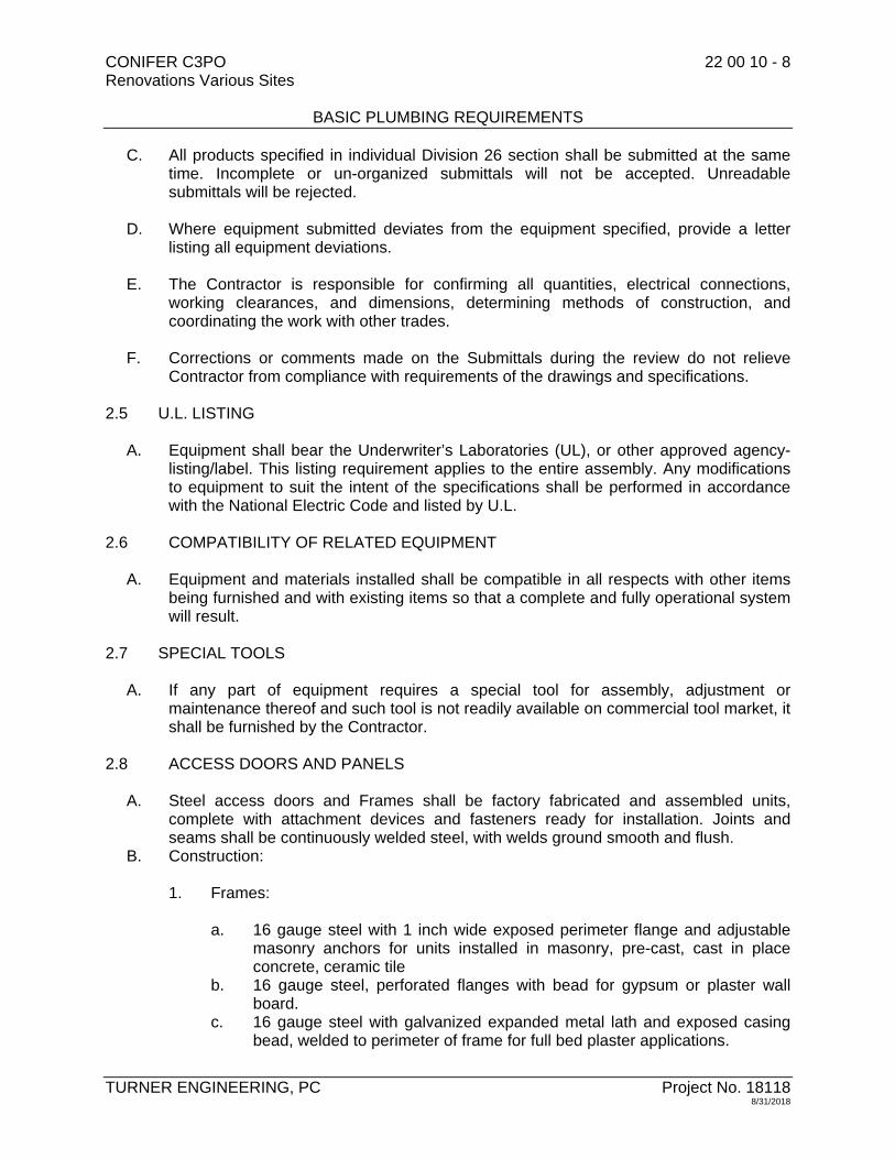
CONIFER C3PO 22 00 10 - 8 Renovations Various Sites BASIC PLUMBING REQUIREMENTS
TURNER ENGINEERING, PC Project No. 18118 8/31/2018
C. All products specified in individual Division 26 section shall be submitted at the same time. Incomplete or un-organized submittals will not be accepted. Unreadable submittals will be rejected.
D. Where equipment submitted deviates from the equipment specified, provide a letter
listing all equipment deviations.
E. The Contractor is responsible for confirming all quantities, electrical connections, working clearances, and dimensions, determining methods of construction, and coordinating the work with other trades.
F. Corrections or comments made on the Submittals during the review do not relieve
Contractor from compliance with requirements of the drawings and specifications. 2.5 U.L. LISTING
A. Equipment shall bear the Underwriter’s Laboratories (UL), or other approved agency-listing/label. This listing requirement applies to the entire assembly. Any modifications to equipment to suit the intent of the specifications shall be performed in accordance with the National Electric Code and listed by U.L.
2.6 COMPATIBILITY OF RELATED EQUIPMENT
A. Equipment and materials installed shall be compatible in all respects with other items being furnished and with existing items so that a complete and fully operational system will result.
2.7 SPECIAL TOOLS
A. If any part of equipment requires a special tool for assembly, adjustment or maintenance thereof and such tool is not readily available on commercial tool market, it shall be furnished by the Contractor.
2.8 ACCESS DOORS AND PANELS
A. Steel access doors and Frames shall be factory fabricated and assembled units, complete with attachment devices and fasteners ready for installation. Joints and seams shall be continuously welded steel, with welds ground smooth and flush.
B. Construction:
1. Frames:
a. 16 gauge steel with 1 inch wide exposed perimeter flange and adjustable masonry anchors for units installed in masonry, pre-cast, cast in place concrete, ceramic tile
b. 16 gauge steel, perforated flanges with bead for gypsum or plaster wall board.
c. 16 gauge steel with galvanized expanded metal lath and exposed casing bead, welded to perimeter of frame for full bed plaster applications.

CONIFER C3PO 22 00 10 - 9 Renovations Various Sites BASIC PLUMBING REQUIREMENTS
TURNER ENGINEERING, PC Project No. 18118 8/31/2018
2. Access Doors:
a. Provide 14 gauge sheet steel flush panel doors with concealed continuous
piano hinge factory installed, primed and painted, set to open 175 degrees. b. Provide fire rated, insulated flush panel doors, with continuous piano hinge
and self closing mechanism rated for 1-1/2 hour “B” labeled, in fire rated partitions.
3. Provide flush, screwdriver operated cam locks on all access doors.
2.9 FIRE STOPPING
A. Fire-stopping for Openings Through Fire and Smoke Rated Walls and Floor Assemblies shall be listed or classified by an approved independent testing laboratory for "Through-Penetration Fire-Stop Systems”. The system shall meet the requirements of "Fire Tests of Through-Penetration Fire-Stops" designated ASTM E814.
B. Acceptable Manufacturers:
1. Dow Corning Fire-Stop System Foams and Sealants. 2. Nelson Electric Fire-Stop System Putty, CLK and WRP. 3. Thomas & Betts - S-100 FS500/600, 4. Carborundum Fyre Putty.
PART 3 - EXECUTION 3.1 SHOP DRAWINGS/PRODUCT DATA/SAMPLES
A. Submit Shop Drawings on all items of equipment and materials to be furnished and installed. Submission of Shop Drawings and samples shall be accompanied by a transmittal letter, stating name of project and contractor, number of drawings, titles, and other pertinent data called for in individual sections. Shop Drawings Shall Be Dated and Contain: Name of project; name of prime professional; name of prime contractor; description or names of equipment, materials and items; and complete identification of locations at which materials or equipment are to be installed. Incomplete submittals will not be accepted. All products specified in an individual Divisions 21, 22, 23, 26, 27, 28 section shall be submitted at the same time. Number each submittal. Indicate deviations from contract requirements on Letter of Transmittal. Corrections or comments made on the Shop Drawings during the review do not relieve Contractor from compliance with requirements of the drawings and specifications. The Contractor is responsible for confirming and correcting all quantities; checking electrical characteristics and dimensions; selecting fabrication processes and techniques of construction; coordinating his work with that of all other trades; and performing his work in a safe and satisfactory manner.

CONIFER C3PO 22 00 10 - 10 Renovations Various Sites BASIC PLUMBING REQUIREMENTS
TURNER ENGINEERING, PC Project No. 18118 8/31/2018
3.2 COORDINATION DRAWINGS
A. Before construction work commences, Contractors for all trades shall submit Coordination Drawings in the form of electronic coordination drawings. Coordination Drawings are required throughout all areas for all trades.
B. Mechanical Equipment Rooms and other critical spaces shall be drawn early in the Coordination Drawing process, simultaneous with all other congested areas.
C. Coordination drawings shall identify and show resolutions of physical conflicts, including but not limited to service clearances, access paths, and clearance to combustibles.
D. Prepare Coordination Drawings As Follows:
1. The Coordination Drawings base file shall consist of the 3-D architectural and structural models depicting all architectural and structural elements that require coordination.
2. The HVAC Contract shall create and prepare the base model file and then include all equipment, ductwork, piping, and diffusers, clearly indicating structure and equipment mounting heights and required working clearances.
a. Submissions of HVAC Contract Documents with contractor title block shall be considered incomplete and will not be acceptable.
b. The HVAC Contract shall visit the site to survey and record architectural and structural elements as required.
3. Upon completion of the HVAC Coordination Drawings file, the HVAC Contract shall provide an electronic 3-D model with hard copy prints to all major trades' Contractors.
4. The Plumbing Contract shall then add all equipment, piping, and sprinkler heads, documenting any conflicts with HVAC ductwork and piping. The P/FP Coordination drawings shall indicate equipment mounting heights and all required pitch.
5. The Electrical Contract shall then add all switchgear, panels, motor control centers, luminaires, cable tray, feeders, and other large equipment, including working clearances that must be coordinated with the other trades.
6. Relocate ductwork, diffusers, and sprinklers as required to coordinate with the structure, ceiling grid, and luminaires.
7. Where conflicts occur, relocate equipment and provide offsets and transitions as required to permit equipment to fit in the space. Clearly document modifications on the drawings for review by the Architect and Engineer. As part of the Contract, relocate equipment, ductwork, piping, etc as required for proper coordination.
8. The Electrical, Plumbing Contract shall indicate areas of conflict and suggested resolutions.
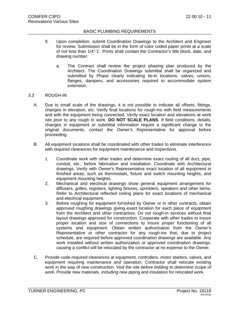
CONIFER C3PO 22 00 10 - 11 Renovations Various Sites BASIC PLUMBING REQUIREMENTS
TURNER ENGINEERING, PC Project No. 18118 8/31/2018
9. Upon completion, submit Coordination Drawings to the Architect and Engineer for review. Submission shall be in the form of color coded paper prints at a scale of not less than 1/4”-1’. Prints shall contain the Contractor’s title block, date, and drawing number.
a. The Contract shall review the project phasing plan produced by the Architect. The Coordination Drawings submittal shall be organized and submitted by Phase clearly indicating tie-in locations, valves, unions, flanges, dampers, and accessories required to accommodate system extension.
3.3 ROUGH-IN
A. Due to small scale of the drawings, it is not possible to indicate all offsets, fittings, changes in elevation, etc. Verify final locations for rough-ins with field measurements and with the equipment being connected. Verify exact location and elevations at work site prior to any rough in work. DO NOT SCALE PLANS. If field conditions, details, changes in equipment or submittal information require a significant change to the original documents, contact the Owner’s Representative for approval before proceeding.
B. All equipment locations shall be coordinated with other trades to eliminate interference with required clearances for equipment maintenance and inspections.
1. Coordinate work with other trades and determine exact routing of all duct, pipe, conduit, etc., before fabrication and installation. Coordinate with Architectural drawings. Verify with Owner's Representative exact location of all equipment in finished areas, such as thermostats, fixture and switch mounting heights, and equipment mounting heights.
2. Mechanical and electrical drawings show general equipment arrangement for diffusers, grilles, registers, lighting fixtures, sprinklers, speakers and other items. Refer to Architectural reflected ceiling plans for exact locations of mechanical and electrical equipment.
3. Before roughing for equipment furnished by Owner or in other contracts, obtain approved roughing drawings giving exact location for each piece of equipment from the Architect and other contractors. Do not rough-in services without final layout drawings approved for construction. Cooperate with other trades to insure proper location and size of connections to insure proper functioning of all systems and equipment. Obtain written authorization from the Owner’s Representative or other contractor for any rough-ins that, due to project schedule, are required before approved coordination drawings are available. Any work installed without written authorization or approved coordination drawings, causing a conflict will be relocated by the contractor at no expense to the Owner.
C. Provide code-required clearances at equipment, controllers, motor starters, valves, and equipment requiring maintenance and operation. Contractor shall relocate existing work in the way of new construction. Visit the site before bidding to determine scope of work. Provide new materials, including new piping and insulation for relocated work.
CONIFER C3PO 22 00 10 - 12 Renovations Various Sites BASIC PLUMBING REQUIREMENTS
TURNER ENGINEERING, PC Project No. 18118 8/31/2018
3.4 EXISTING SYSTEMS AND CONDITIONS
A. Prior to beginning work, inspect and test all existing electrical systems that will be affected by the work in this contract. Provide a report to the Owner indicating any problems or defects found. If no problems or system defects are submitted, the contractor shall be responsible for correcting problems found at the completion of the project that are determined to be caused by the work of this contract.
B. Inspect the entire work area for defects in the existing construction such as scratches, holes etc. Submit a complete list with photographs of existing damage to the Owner prior to beginning work. If existing damage is not documented, the contractor may be required to repair all damage to like new condition.
C. Where connections are made to existing systems, carefully examine the condition of the piping and related materials including hangers and support structure. Immediately report to the Architect any extraordinary corrosion, thinning, restriction, narrowing or other degradation.
D. Where connections are made to existing underground/underfloor sanitary or storm drainage, provide camera inspection of the flow path from the point of connection to a point outside the foundation wall (including flushing/cleaning required for the inspection) to verify the integrity of the existing underground piping. Exception: not required in sections of underground sanitary or storm known to be active and frequently used. Architect and Owner shall be consulted prior to applying this exception.
3.5 PROTECTION OF PERSONS AND PROPERTY
A. Contractor shall assume responsibility for Construction Safety at all times and provide, as part of contract, all trench or building shoring, scaffolding, shielding, dust/fume protection, mechanical/electrical protection, special grounding, safety railings, barriers, and other safety feature required to provide safe conditions for all workmen and site visitors.
3.6 ASBESTOS RECOGNITION AND PRECAUTIONS
A. The contractor shall be responsible for coordination of all required removal work, coring, cutting and patching with the Owner’s asbestos management plan. Prior to performing such work identify areas containing asbestos. Notify the Owner so that they may make arrangements for abatement and/or containment prior to work proceeding. The contractor shall be responsible for cleaning all areas where asbestos is released due to the failure to coordinate with the asbestos management plan. Refer to Division 01 sections for further requirements.

CONIFER C3PO 22 00 10 - 13 Renovations Various Sites BASIC PLUMBING REQUIREMENTS
TURNER ENGINEERING, PC Project No. 18118 8/31/2018
B. The disturbance or dislocation of asbestos-containing materials causes asbestos fibers to be released into the building's atmosphere, thereby creating a health hazard to workmen and building occupants. Consistent with Industrial Code Rule 56 and the content of recognized asbestos-control work, the Contractor shall apprise all of his workers, supervisory personnel, subcontractors, Owner and Consultants who will be at the job site of the seriousness of the hazard and of proper safeguards and work procedures which must be followed, as described in New York State Department of Labor Industrial Code Rule 56. Fluorescent Bulbs which are not specifically designated as not containing Mercury shall be disposed of in compliance with the requirements of the New York State Department of Environmental Conservation and all applicable Federal Laws.
C. Refer to Division 02 sections for further requirements.
3.7 REMOVALS
A. Where existing equipment removals are called for, submit complete list to Owner's Representative. All items that Owner wishes to retain that do not contain asbestos or PCB Material shall be delivered to location directed by Owner. Items that Owner does not wish to retain shall be removed from site and legally disposed of. Removal and disposal of material containing asbestos and/or PCB's shall be in accordance with Federal, State and Local law requirements. Where equipment is called for to be relocated. Contractor shall carefully remove, clean and recondition, then reinstall. Remove all abandoned piping, wiring, equipment, lighting, ductwork, tubing, supports, fixtures, etc. Visit each room, crawl spaces and roofs to determine total Scope of Work. The disturbance or dislocation of asbestos-containing materials causes asbestos fibers to be released into the building's atmosphere, thereby creating a health hazard to workmen and building occupants. Consistent with Industrial Code Rule 56 and the content of recognized asbestos-control work, the Contractor shall apprise all of his workers, supervisory personnel, subcontractors, Owner and Consultants who will be at the job site of the seriousness of the hazard and of proper safeguards and work procedures which must be followed, as described in New York State Department of Labor Industrial Code Rule 56.
B. Completely remove all piping, conduit, controls, and other devices associated with the equipment not to be reused in the new work. This includes all pipe, valves, fittings, insulation, conduit, panels, and all hangers, including the top connection and any fastenings to building structural systems. Seal all openings, after removal of equipment, pipes, ducts, conduits and other penetrations in roof, walls, floors, in an approved manner and in accordance with plans and specifications where specifically covered. Structural integrity of the building system shall be maintained. Reference shall also be made to the architectural, structural, mechanical, site, and electrical drawings and specifications for additional facilities to be demolished or handled.

CONIFER C3PO 22 00 10 - 14 Renovations Various Sites BASIC PLUMBING REQUIREMENTS
TURNER ENGINEERING, PC Project No. 18118 8/31/2018
3.8 STORAGE AND PROTECTION OF MATERIALS
A. Store Materials on dry base, at least 6 inches above ground or floor. Store so as not to interfere with other work or obstruct access to buildings or facilities. Provide waterproof/windproof covering. Remove and provide special storage for items subject to moisture damage. Protect against theft or damage from any cause. Replace items stolen or damaged, at no cost to Owner.
B. Refer to "General Conditions of the Contract for Construction."
3.9 FREEZING AND WATER DAMAGE
A. Take all necessary precautions with equipment, systems and building to prevent damage due to freezing and/or water damage. Repair or replace, at no change in contract, any such damage to equipment, systems and building. Perform first seasons winterizing in presence of Owner's operating staff.
3.10 CUTTING AND PATCHING
A. Each trade shall include their required cutting and patching work unless shown as part of the General Construction work on the architectural drawings. Refer to "General Conditions of the Contract for Construction”, for additional requirements. Cut and drill from both sides of walls and/or floors to eliminate splaying. Patch, cut or abandoned holes left by removals of equipment or fixtures. Patch adjacent existing work disturbed by installation of new work including insulation, walls and wall covering, ceiling and floor covering, other finished surfaces. Patch openings and damaged areas equal to existing surface finish. Cut openings in prefabricated construction units in accordance with manufacturer's instructions.
3.11 CONCEALMENT
A. Conceal all contract work above ceilings and in walls, below slabs, and elsewhere throughout building. If concealment is impossible or impractical, notify Owner's Representative before starting that part of the work and install only after his review. In areas with no ceilings, install only after Owner's Representative reviews and comments on arrangement and appearance.
3.12 CHASES
A. In Existing Buildings:
1. Drill holes for floor and/or roof slab openings. 2. Multiple pipes smaller than 1 inch properly spaced and supported may pass
through one 6 inches or smaller diameter opening. 3. Seal voids in fire rated assemblies with a fire-stopping seal system to maintain
the fire resistance of the assembly. Provide 18 gauge galvanized sleeves at fire rated assemblies. Extend sleeves 2 inches above floors.

CONIFER C3PO 22 00 10 - 15 Renovations Various Sites BASIC PLUMBING REQUIREMENTS
TURNER ENGINEERING, PC Project No. 18118 8/31/2018
4. In wall openings, drill or cut holes to suit. Provide 18 gauge galvanized sleeves at shafts and fire rated assemblies. Provide fire-stopping seal between sleeves and wall in drywall construction. Provide fire-stopping similar to that for floor openings.
3.13 FIRE-STOPPING
A. Fire-stopping for Openings Through Fire and Smoke Rated Wall and Floor Assemblies:
1. Provide materials and products listed or classified by an approved independent testing laboratory for "Through-Penetration Fire-Stop Systems”. The system shall meet the requirements of "Fire Tests of Through-Penetration Fire-Stops" designated ASTM E814.
2. Provide fire-stop system seals at all locations where piping, tubing, conduit, electrical busways/cables/wires, ductwork and similar utilities pass through or penetrate fire rated wall or floor assembly. Provide fire-stop seal between sleeve and wall for drywall construction.
3. The minimum required fire resistance ratings of the wall or floor assembly shall be maintained by the fire-stop system. The installation shall provide an air and watertight seal.
4. The methods used shall incorporate qualities, which permit the easy removal or addition of electrical conduits or cables without drilling or use of special tools. The product shall adhere to itself to allow repairs to be made with the same material and permit the vibration, expansion and/or contraction of any items passing through the penetration without cracking, crumbling and resulting reduction in fire rating.
5. Apply fire stopping within the temperature and humidity limits permitted by the manufacturer.
6. Provide rigid steel sleeves where non-armored cables pass through fire rated walls and barriers.
3.14 FLASHING AND SEALING
A. Opening through roofs shall be flashed in manner not to affect roof guarantee or bond. Engage qualified Roofing Contractor licensed by the Roofing manufacturer, as part of contract. Provide non-ferrous flashing pieces, skirts, hoods and collars as required to make ducts, pipes, conduits, and other penetrations watertight. Where curbs are called for with respect to rectangular openings in new roofs, flashing will be done by others unless specifically indicated otherwise. Caulk and waterproof with additional material so as to seal airtight and watertight.
B. Apply all flashing and sealers within the temperature and humidity limits permitted by the manufacturer.

CONIFER C3PO 22 00 10 - 16 Renovations Various Sites BASIC PLUMBING REQUIREMENTS
TURNER ENGINEERING, PC Project No. 18118 8/31/2018
3.15 SUPPORTS
A. Provide required supports, beams, angles, hangers, rods, bases, braces, and other items to properly support contract work. Supports shall meet the approval of the Owner's Representative. Modify studs, add studs, add framing, or otherwise reinforce studs in metal stud walls and partitions as required to suit contract work. If necessary, in stud walls, provide special supports from floor to structure above. For Precast Panels/Planks and Metal Decks, support mechanical/electrical work as determined by manufacturer and Owner's Representative. Provide heavy gauge steel mounting plates for mounting contract work. Mounting plates shall span two or more studs. Size, gauge, and strength of mounting plates shall be sufficient for equipment size, weight, and desired rigidity.
3.16 GENERAL INSTALLATIONS REQUIREMENTS
A. Coordinate the installation of required supporting devices and sleeves to be set in poured-in-place concrete and other structural components, as they are constructed
B. Coordinate ordering and installation of all equipment with long lead times or having a major impact on work by other trades so as not to delay the job or impact the construction schedule. Pay close attention to equipment that must be installed prior to building enclosure.
C. Where mounting heights are not detailed or dimensioned, install systems, materials and equipment to provide the maximum headroom possible.
D. Set all equipment to accurate line and grade, level all equipment and align all equipment components.
E. Provide all scaffolding, rigging, hoisting and services necessary for erection and delivery of equipment and apparatus furnished into the premises. These items shall be removed from premises when no longer required.
F. No equipment shall be hidden or covered up prior to inspection by the Owner’s Representative. All work that is determined to be unsatisfactory shall be corrected immediately.
G. All work shall be installed level and plumb, parallel and perpendicular to other building systems and components.
H. Install access panels or doors where units are concealed behind finished surfaces.
I. Provide wraps meeting ADA/code requirements on all accessible fixtures and equipment.
J. Provide independent supports for equipment or systems – do not support equipment or other systems from sprinkler, plumbing or other piping/supports.

CONIFER C3PO 22 00 10 - 17 Renovations Various Sites BASIC PLUMBING REQUIREMENTS
TURNER ENGINEERING, PC Project No. 18118 8/31/2018
3.17 PAINTING
A. This Contract Includes the following:
1. Painting for all cut and patch work performed as part of Divisions 21, 22, 23, 26, 27, 28 contract.
2. Painting required for touch-up of surfaces damaged due to the installation of Divisions 21, 22, 23, 26, 27, 28 work.
3. Painting as required to repair finish of equipment furnished. 4. Painting as called for on Divisions 21, 22, 23, 26, 27, 28 Drawings.
3.18 ADDITIONAL ENGINEERING SERVICES
A. In the event that the Consultant is required to provide additional engineering services as a result of substitution of equivalent materials or equipment by the Contractor, or changes by the Contractor in dimension, weight, power requirements, etc., of the equipment and accessories furnished, or if the Consultant is required to examine and evaluate any changes proposed by the Contractor for the convenience of the Contractor, then the Consultant's expenses in connection with such additional services shall be paid by the Contractor and may be deducted from any moneys owed to the Contractor.
B. In the event that the Consultant is required to provide additional engineering services as a result of Contractor's errors, omissions or failure to conform to the requirements of the Contract Documents, or if the Consultant is required to examine and evaluate any changes proposed by the Contractor solely for the convenience of the Contractor, then the Consultant's expense in connection with such additional services shall be paid by the Contractor and may be deducted from any moneys owed to the Contractor.
3.19 TEMPORARY FACILITIES
A. Refer to the standard General Conditions of the contract for Construction and Supplemental General Conditions.
1. Continuity of operation of existing facilities will require temporary installation or relocation of equipment and piping.
2. All piping and equipment shall be properly supported, sloped to drain, operate without excessive stress, and shall be insulated where injury can occur to personnel by contact with operating facilities.
3. Temporary facilities and piping shall be completely removed and any openings in structures sealed. Provide necessary blind flanges and caps to seal open piping remaining pressurized.

CONIFER C3PO 22 00 10 - 18 Renovations Various Sites BASIC PLUMBING REQUIREMENTS
TURNER ENGINEERING, PC Project No. 18118 8/31/2018
3.20 CLEANING
A. It is the Contractor's responsibility to keep clean all equipment and fixtures provided under this contract for the duration of the project. Each trade shall keep the premises free from an accumulation of waste material or rubbish caused by his operations. The facilities require an environment of extreme cleanliness, and it is the Contractor's responsibility to adhere to the strict regulations regarding procedures on the existing premises. After all tests are made and installations completed satisfactorily:
1. Thoroughly clean entire installation, both exposed surfaces and interiors. 2. Remove all debris caused by work. 3. Remove tools, surplus, materials, when work is finally accepted.
3.21 HVAC EQUIPMENT CONNECTIONS
A. Provide final condensate, hot water, glycol, chilled and condenser water, drain, vent and gas connections to all equipment as required by the equipment. Provide final connections, including domestic water piping, wiring, controls, and devices from equipment to outlets left by other trades. Provide equipment waste, drip, overflow and rail connections extended to floor drains.
B. Provide as part of Plumbing Work valved water outlet adjacent to equipment requiring same. Provide equipment type floor drains, or drain hubs, adjacent to equipment.
C. Provide for Owner Furnished and Contractor furnished equipment all valves, piping, piping accessories, traps, pressure reducing valves, gauges, relief valves, vents, drains, insulation, sheet metal work, controls, dampers, as required.
D. Refer to manufacturer drawings and specifications for requirements of medical equipment, laboratory equipment and special equipment. Verify connection requirements before bidding.
3.22 PLUMBING EQUIPMENT CONNECTIONS
A. Provide complete plumbing connections to all plumbing equipment. Provide control connections to equipment where indicated on the drawings. Provide valves on piping ahead of each piece of equipment.
B. Provide all piping, trim, accessories and connections as required for proper equipment operation of Equipment provided by this contract, Owner-Furnished Equipment and Equipment furnished by other contracts,
C. Refer to Manufacturer's drawings/specifications for requirements of special equipment. Verify connection requirements before bidding and confirm prior to roughing.

CONIFER C3PO 22 00 10 - 19 Renovations Various Sites BASIC PLUMBING REQUIREMENTS
TURNER ENGINEERING, PC Project No. 18118 8/31/2018
3.23 PLUMBING INSTALLATIONS
A. All installations shall comply with the following requirements:
1. Coordinate plumbing systems, equipment, and materials installation with other building components. Be responsible for any changes in openings and locations necessitated by the equipment installed.
2. The Architect shall control the placement of all wall and ceiling mounted plumbing equipment and devices in all rooms with the exception of mechanical and electrical equipment rooms. When drawing details are not available, consult with the Architects representative for actual location.
3. Verify all dimensions with field measurements. 4. Arrange for all chases, slots and openings in other building components that are
not indicated on drawings, to allow for plumbing installations. 5. Coordinate the installation of required supporting devices and sleeves to be set
in poured-in-place concrete and other structural components, as they are constructed.
6. Coordinate ordering and installation of all equipment with long lead times or having a major impact on work by other trades so as not to delay the job or impact the construction schedule. Pay close attention to equipment that must be installed prior to building enclosure.
7. Where mounting heights are not detailed or dimensioned, install systems, materials and equipment to provide the maximum headroom possible.
8. Install systems, materials and equipment to conform with approved submittal data, including coordination drawings, to greatest extent possible. Conform to arrangements indicated by the Contract Documents, recognizing that portions of the work are shown only in diagrammatic form. Where coordination requirements conflict with individual system requirements, refer the conflict to the Architect.
9. Store Materials on dry base, at least 6 inches above ground or floor. Store so as not to interfere with other work or obstruct access to buildings or facilities. Provide waterproof/windproof covering. Remove and provide special storage for items subject to moisture damage. Protect against theft or damage from any cause. Replace items stolen or damaged, at no cost to Owner.
10. Set all equipment to accurate line and grade, level all equipment and align all equipment components.
11. All tolerances in alignment and leveling, and the quality of workmanship for each stage of work shall be as required by the manufacturer and subject to approval by the Owner’s Representative.
12. All finished equipment surfaces damaged during construction shall be brought to “as new” condition by touch up or repainting. Any rust shall be removed and primed prior to repainting.
13. Provide all scaffolding, rigging, hoisting and services necessary for erection and delivery of equipment and apparatus furnished into the premises. These items shall be removed from premises when no longer required.
14. No plumbing equipment shall be hidden or covered up prior to inspection by the Owner’s Representative. All work that is determined to be unsatisfactory shall be corrected immediately.
15. All plumbing work shall be installed level and plumb, parallel and perpendicular to other building systems and components.

CONIFER C3PO 22 00 10 - 20 Renovations Various Sites BASIC PLUMBING REQUIREMENTS
TURNER ENGINEERING, PC Project No. 18118 8/31/2018
16. Conceal all contract work above ceilings and in walls, below slabs, and elsewhere throughout building. If concealment is impossible or impractical, notify Owner's Representative before starting that part of the work and install only after his approval. In areas with no ceilings, install only after Owner's Representative reviews and comments on arrangement and appearance.
17. Install access panels or doors where units are concealed behind finished surfaces.
3.24 ELECTRICAL EQUIPMENT CONNECTIONS
A. Provide complete power connections to all electrical equipment. Provide control connections to equipment where indicated on the drawings. Provide disconnect ahead of each piece of equipment. Ground all equipment in accordance with the latest edition of the NEC.
B. Provide all power wiring, electric equipment, switches, lights, receptacles, and connections as required for proper equipment operation of Owner-Furnished Equipment and Equipment furnished by other contracts. Provide control wiring where noted in the documents.
C. Refer to Manufacturer's drawings/specifications for requirements of special equipment. Verify connection requirements before bidding and confirm prior to roughing.
3.25 CONTINUITY OF SERVICES
A. The building will be in use during construction operations. Maintain existing systems in operation within all rooms of building at all times. Refer to "General Conditions of the Contract for Construction" for temporary facilities for additional contract requirements. Schedules for various phases of contract work shall be coordinated with all other trades and with Owner's Representative. Provide, as part of contract, temporary plumbing and fire protection, mechanical and electrical connections and relocation as required to accomplish the above. Obtain approval in writing as to date, time, and location for shut-down of existing mechanical/electrical facilities or services.
3.26 START UP AND OWNER INSTRUCTIONS
A. Before acceptance of the work, furnish necessary skilled labor to operate all systems by seasons. Instruct the Owner’s designated personnel on the proper operation and maintenance of systems and equipment. Obtain written acknowledgment from person instructed prior to acceptance repeat the instructions if asked to do so. Contractor is fully responsible for systems until acceptance, even though operated by Owner's personnel, unless otherwise agreed in writing. Provide operating, maintenance and starting precautions and procedures to be followed by the Owner for operating systems and equipment. Mount the instruction in clear plastic holder on or adjacent to the equipment.

CONIFER C3PO 22 00 10 - 21 Renovations Various Sites BASIC PLUMBING REQUIREMENTS
TURNER ENGINEERING, PC Project No. 18118 8/31/2018
B. Where supervision by a manufacturer is called for, provide manufacturer’s certified technician or engineer to supervise the startup, testing and adjustment of the equipment or system. Where two or more manufacturers are involved (i.e. variable frequency drive and air handling unit) both manufacturers shall be present at start up. The manufacturer shall provide a written report detailing the testing and start-up including problems that occurred and their method of resolution.
3.27 OPERATION AND MAINTENANCE MANUALS
A. Provide Operation and Maintenance Manuals. Include one copy each of approved Shop Drawings, wiring diagrams, piping diagrams, spare parts lists, as-built drawings and manufacturer's instructions. Include typewritten instructions, describing equipment, starting/operating procedures, emergency operating instructions, seasonal changeover, freeze protection, precautions and recommended maintenance procedures. Include name, address, and telephone number of supplier manufacturer Representative and service agency for all major equipment items. Bind above items in a three ring binder with name of project on the cover. Deliver to Owner's Representative before request for acceptance.
3.28 RECORD DOCUMENTS
A. Maintain a clean set of marked up as-built documents on the job site, and document all variances from the contract documents.
B. Prepare record documents in accordance with the General and Supplementary Conditions of the Contract.
3.29 SALVAGEABLE MATERIALS
A. Salvageable materials will be reviewed and identified by the Owner. Instruction shall be given to the Contractor whether the Owner will remove salvageable materials, or whether contractor is to remove and deliver salvageable materials to a pre designated site.
B. Plumbing Items normally accepted as salvage by the Owner:
1. Fixtures 2. Pumps
END OF SECTION 22 00 10


CONIFER C3PO 22 05 20 - 1 Renovations Various Sites VALVES
TURNER ENGINEERING, PC Project No. 18118 8/31/2018
SECTION 22 05 20 - VALVES
PART 1 - GENERAL
1.1 WORK INCLUDED
A. Provide labor, materials, equipment and services to perform operations required for the complete installation and related Work as required in Contract Documents.
1.2 SUBMITTALS
A. All valves and accessories listed under “Part 2 – Products” of this Section.
B. Provide valve cut sheets and component diagrams, specifications and dimensional drawings for all valves to be utilized on the project.
PART 2 – PRODUCTS
2.1 VALVES
A. General: All valves shall comply with and have following requirements:
1. Working pressure stamped or cast on bodies per MSS SP-25. 2. All stem packing serviceable without removing valve from line and shall be free of
asbestos. 3. All valves located on potable water systems shall be “lead-free” in compliance
with NSF-61.
B. Makes:
1. Gate, globe and check valves: Milwaukee, Nibco, Watts. 2. Ball valves: Apollo (Conbraco), Milwaukee, Nibco, Watts. 3. Butterfly valves: Demco, DeZurik, Keystone, Milwaukee, Watts. 4. Balance valves: Bell & Gossett, Armstrong, Taco. 5. To establish a standard of quality and identify features, certain manufacturer's
numbers are given in the following paragraphs.
C. Gate Valves:
1. 2-1/2 inches and larger: IBBT, solid or double wedge disc, OS&Y flanged, 125 swp, Milwaukee F-2885.
D. Globe valves:
1. 2-1/2 inches and larger: IBBT, renewable seat and disc, OS&Y, 125 swp, flanged, Milwaukee F-2981.

CONIFER C3PO 22 05 20 - 2 Renovations Various Sites VALVES
TURNER ENGINEERING, PC Project No. 18118 8/31/2018
2. 2 inches and smaller: Bronze, renewable composition or PTFE disc, threaded bonnet, rising stem, 300 psi (WOG). Screwed ends, Milwaukee UP502. Solder ends, Milwaukee UP1502.
E. Check Valves:
1. 2 inches and smaller: Bronze, swing check, 600 psi (WOG). Screwed ends, Milwaukee UP509. Solder ends, Milwaukee UP1509. Provide in horizontal position only.
2. 2 inches and smaller: Bronze, lift check, 400 psi wog, PTFE seat, stainless steel guide rod and stainless steel spring. Screwed ends, Nibco T-480-Y-LF. Solder ends, Nibco S-480-Y-LF. Provide in vertical or horizontal positions.
3. Silent check valves: Globe type, semi-steel body with bronze trim and stainless steel spring, 250 lb. ASA, Milwaukee Series 1400.
F. Ball Valves:
1. 2 inches and under: Bronze body, two piece, 600 psi (WOG), full port openings, chrome plated steel ball and stem, teflon seats, end entrance. Screwed (threaded) ends, Watts LFFBV. Solder (sweat) ends, Watts LFB6081G2.
G. Balance Valves:
1. Calibrated balance valve with provisions for connecting a portable differential pressure meter suitable as a service valve. Meter connections to have built-in check valves. An integral pointer shall register degree of valve openings. Valve shall have internal seals.
2. Balance valves sizes shall be based upon gpm range rather than pipe size.
Balance Valve Size GPM Range
1/2” up to 2.5
3/4” 2.5 - 4.5
1” 4.5 - 10
1-1/4” 10 - 15
1-1/2” 15 - 30
2” 30 - 60
3. Design equipment: Armstrong CBV Series.
H. Valves For Gauges And Instruments:
1. 1/4 inch size: Brass bar stock for 1000 psi and 300°F; Trerice No. 735 needle valve.

CONIFER C3PO 22 05 20 - 3 Renovations Various Sites VALVES
TURNER ENGINEERING, PC Project No. 18118 8/31/2018
I. Gas Valves and Regulators:
1. Valves 2 inches and smaller: Bronze body, screwed ends, AGA approved and UL listed. Milwaukee BB2-100.
2. Gas Regulators: Line sized appliance regulators with an inlet pressure rating of ½ PSI and a maximum outlet pressure rating of 8” wc.
3. Solenoid Valves for gas line emergency shutoff ASCO#8030A17 normally closed operation, IRI approved, UL listed, two way valve with BUNA N diaphragm, 120 Volt AC.
J. Hose Thread Drain Valves:
1. Bronze body with interchangeable solid bronze wedge and screwed-in bonnet, with hose thread end, brass cap and chain, 600 psi WOG, 200 psi, Milwaukee BA-100H FNPT X Male Hose or BA-150H soldered X male hose. Ball valve with brass cap and chain on hose end.
PART 3 – EXECUTION
3.1 INSTALLATION
A. General:
1. Provide valves of type called for and where required to service equipment and fixtures.
2. Use extreme care and caution when soldering valve connections to piping to prevent valve seat damage. Apply heat with the flame directed away from the center of the valve body. Inspect all valves after soldering, tighten valve packing nut and make adjustments if required to ensure valve operates properly.
3. Provide at all major building and all systems sections and where noted on the Drawings.
4. Locate valves with stems at or above horizontal positions and swing check valves in horizontal position only.
5. Ball valves shall be used for all domestic water service unless otherwise noted. 6. Provide hose threaded drain valves at all low points, strainers, equipment and as
called for. Provide hose threaded drain valves at all system low points, at all elevation changes and at all building intersections for all plumbing and fire protection systems. In addition to these requirements, provide drains where specifically indicated on the Drawings.
7. Provide balance valves as recommended by the manufacturer; provide all required and recommended pipe diameter clearances upstream and downstream from each balance valve provided.
END OF SECTION 22 05 20


CONIFER C3PO 22 05 30 - 1 Renovations Various Sites PLUMBING IDENTIFICATION
TURNER ENGINEERING, PC Project No. 18118 8/31/2018
SECTION 22 05 30 - PLUMBING IDENTIFICATION
PART 1 - GENERAL
1.1 WORK INCLUDED
A. Provide labor, materials, equipment and services as required for the complete installation designed in Contract Documents.
1.2 QUALIFICATIONS
A. All identification devices shall comply with ANSI A13.1 for lettering size, length of color field, colors and viewing angles.
1.3 SUBMITTALS
A. Submit product data for each identification material and device and for all items specified under “Part 2 - Products” of this Section.
B. Submit valve schedule for all piping systems typewritten on 8-1/2 inch x 11 inch paper, indicating code number, location and valve function.
C. Submit schedule of piping, equipment and valve identification for review before labeling.
1.4 ACCEPTABLE MANUFACTURERS
A. Allen Systems, Inc., W.H. Brady Co., Calpico, Craftmark Identification Systems or Seton Name Plate Corp.
PART 2 - PRODUCTS
2.1 GENERAL
A. Provide manufacturer's products of categories and types required for each application.
2.2 PIPING IDENTIFICATION
A. Pipe Labels (Inside buildings):
1. Piping/Insulation with outside diameter of 5-7/8 inches and less: Provide acrylic plastic wrap-around type markers with directional flow arrows, UV resistance and legend printed four (4) times for 360 degree visibility. Make: Seton “Setmark” snap-on wrap around type pipe markers.

CONIFER C3PO 22 05 30 - 2 Renovations Various Sites PLUMBING IDENTIFICATION
TURNER ENGINEERING, PC Project No. 18118 8/31/2018
B. Pipe labels shall conform to the following identification table:
PIPE SERVICE IDENTIFICATION / LABEL
Domestic Cold Water DOMESTIC COLD WATER
Domestic Hot Water DOMESTIC HOT WATER
Natural Gas NATURAL GAS
Sanitary and / or Waste SANITARY DRAIN
Plumbing Vent SANITARY VENT
Indirect Waste INDIRECT WASTE
2.3 VALVE IDENTIFICATION
A. Valve Tags:
1. Standard brass valve tags, 2 inch diameter with 1/2 inch high numerals. Identify all plumbing services with 1/4" letters above the valve number (“PLBG.”). Attach to valves using brass “jack” chain and brass “S” hook. Make: Seton Style No. M4507 tags, Style No. 16182 chain and Style No. 16195, 6 and 7 No. hooks.
B. Valve Chart:
1. Provide valve chart for all valves provided as a part of this project. Frame and place under clear glass. Hang in Mechanical Room or in location as directed by the Owner.
PART 3 - EXECUTION
3.1 GENERAL
A. Provide valve tags for all valves provided on project. Provide a valve tag chart for all valves provided on the project.
B. Provide piping identification with directional flow arrows for all piping on project.
END OF SECTION 22 05 30

CONIFER C3PO 22 07 00 - 1 Renovations Various Sites INSULATION
TURNER ENGINEERING, PC Project No. 18118 8/31/2018
SECTION 22 07 00 - INSULATION
PART 1 - GENERAL
1.1 WORK INCLUDED
A. Provide labor, materials, equipment and services to perform operations required for the complete installation and related Work as required in Contract Documents.
1.2 SUBMITTALS
A. Manufacturer data. Schedule of insulation applications.
PART 2 - PRODUCTS
2.1 GENERAL
A. Insulation, jackets, adhesives and coatings shall comply with the following:
1. Treatment of jackets or facings for flame and smoke safety must be permanent. Water soluble treatments not permitted.
2. Insulation, including finishes and adhesives on the exterior surfaces of ducts, pipes and equipment, shall have a flame spread rating of 25 or less and a smoke developed rating of 50.
3. Asbestos or asbestos bearing materials not permitted.
2.2 PIPE INSULATION (RIGID TYPE)
A. Preformed rigid sectional pipe covering, 4 lb nominal density fiberglass. Maximum thermal conductivity (k), on a flat surface, shall be 0.27 Btu/sq. ft. hr. °F/in. at 75°F mean temperature. White Kraft outer surface bonded to aluminum foil and reinforced with fiberglass yarn.
2.3 PIPE INSULATION (FLEXIBLE TYPE)
A. Flexible, unicellular elastomeric foam type, fire retardant insulation.
2.4 PLASTIC JACKETING
A. PVC jacket, 20 mill thickness. Solvent adhesive welded joints.
2.5 MAKE
A. Fiberglass: Certainteed, Knauf, Manville, Owens-Corning, or approved equal.
B. Flexible Elastomeric: Armstrong, Manville, Rubatex, or approved equal.
C. Adhesives: Benjamin Foster (BF), Mono-Eco, Tremco; numbers designate quality of adhesive.

CONIFER C3PO 22 07 00 - 2 Renovations Various Sites INSULATION
TURNER ENGINEERING, PC Project No. 18118 8/31/2018
2.6 MATERIALS AND SCHEDULES
A. See Exhibits at the end of this section.
PART 3 - EXECUTION
3.1 GENERAL REQUIREMENTS
A. Provide Thermal Insulation:
1. Insulation is required on piping unless otherwise called for. 2. Only on clean, dry surfaces and after work has been tested. 3. On cold surfaces with continuous unbroken vapor seal. 4. Exposed surfaces shall be white. 5. Pipes individually insulated.
B. Do not cover inspection stampings, openings, petcocks, handholes, manholes, access doors, plugged outlets, air vents, plugged openings or petcocks.
3.2 PIPE INSULATION
A. Insulate piping systems including fittings, valves, flanges, unions, strainers and other attachments installed in piping system, whether exposed or concealed.
B. Piping In Exterior Walls, Spaces, Overhangs, Attics, Or Where Subject To Freezing: Insulate pipe with double the thickness called for. Piping In Wall Chases: In addition to the above, pack chase with loose glass fiber insulation.
C. Plumbing Fixtures and Equipment:
1. Install insulation on exposed hot and cold plumbing piping to within 18 inches of fixture or equipment connection.
2. Insulate exposed domestic hot water and waste piping for plumbing fixtures designated for use by the handicapped.
D. Joints In Section Pipe Covering Made As Follows:
1. Standard: Longitudinal laps and butt joint sealing strips cemented with BF 85-20 or factory applied pressure sensitive adhesive lap seal. Stapled with outward clinching staples.
2. Vapor barrier: For cold services, Longitudinal laps and 4 inch vapor barrier strip at butt joints shall be sealed with white BF 85-20. Seal ends of pipe insulation at valves, flanges and fittings with white BF 85-20.

CONIFER C3PO 22 07 00 - 3 Renovations Various Sites INSULATION
TURNER ENGINEERING, PC Project No. 18118 8/31/2018
E. Fittings, Valves And Flanges:
1. Hot and cold water:
a. Concealed: Insulating cement of the same thickness as adjacent pipe insulation. Cold water to be vapor sealed with BF 30-36 "Seal-Fas".
b. Exposed: Premolded fitting covers of the same material and thickness as the adjacent pipe insulation and finished with glass cloth applied and coated with BF 30-36 "Seal-Fas”.
2. Optional: In lieu of the standard method above, the Contractor has the option of using Zeston, Ceel-Tite System, or Proto. Tape all joints at covers.
F. Flexible Pipe Insulation:
1. Split longitudinal joint and seal with adhesive. 2. Fittings made from miter-cut pieces properly sealed with adhesive, or ells may be
continuous. 3. Where exposed, apply white paint as recommended by manufacturer.
3.3 EXISTING INSULATION
A. Patch existing insulation damaged during the course of the work.
3.4 EXISTING WORK
A. Insulate all exposed existing piping and equipment that is not currently insulated or the existing insulation is damaged.
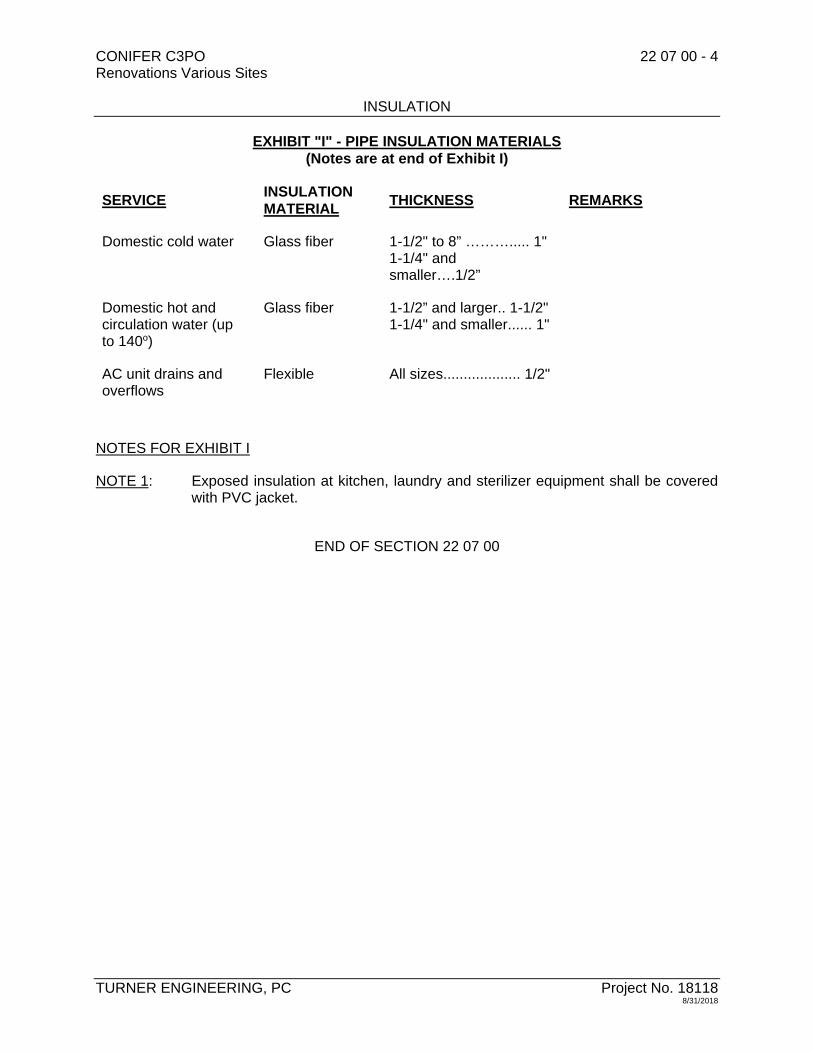
CONIFER C3PO 22 07 00 - 4 Renovations Various Sites INSULATION
TURNER ENGINEERING, PC Project No. 18118 8/31/2018
EXHIBIT "I" - PIPE INSULATION MATERIALS (Notes are at end of Exhibit I)
SERVICE INSULATION MATERIAL
THICKNESS REMARKS
Domestic cold water Glass fiber
1-1/2" to 8” ………..... 1"1-1/4" and smaller….1/2”
Domestic hot and circulation water (up to 140o)
Glass fiber
1-1/2” and larger.. 1-1/2"1-1/4" and smaller...... 1"
AC unit drains and overflows
Flexible All sizes................... 1/2"
NOTES FOR EXHIBIT I
NOTE 1: Exposed insulation at kitchen, laundry and sterilizer equipment shall be covered with PVC jacket.
END OF SECTION 22 07 00

CONIFER C3PO 22 10 10 - 1 Renovations Various Sites PIPING SYSTEMS AND ACCESSORIES
TURNER ENGINEERING, PC Project No. 18118 8/31/2018
SECTION 22 10 10 - PIPING SYSTEMS AND ACCESSORIES
PART 1 – GENERAL
1.1 WORK INCLUDED
A. Provide labor, materials, equipment and services to perform operations required for the complete installation and related Work as required in Contract Documents.
1.2 SUBMITTALS
A. Schedule of all pipe materials, fittings and connections to be utilized on this Project.
B. Provide submittal information for all pipe, fittings and connections to be utilized on this project.
C. Submit shop drawings and descriptive literature, showing dimensions, joint and other details for each type and class of pipe, fitting and restraint system to be furnished for the project. All materials furnished under the Contract shall be manufactured only in accordance with the specifications. Submittals shall include material information, dimensions, pipe class information, weights, coating and lining system data.
D. Submit manufacturer’s Certificates of Compliance with these specifications and certification that the ductile iron pipe fittings have been manufactured and tested in accordance with AWWA/ANSI specifications.
E. Submit a detailed description of proposed testing, flushing and disinfection procedures to be used for this project. The description shall contain the name of the person responsible for the testing, flushing and disinfection work, equipment to be used, chemical to be used, method of measuring flow during flushing procedures and the name of the laboratory to be used for analysis. Review of the description shall not be construed as approval of any methods to be used; the Contractor shall be fully responsible for achieving the specified test results.
PART 2 – PRODUCTS
2.1 GENERAL
A. All piping and fittings used on this Project shall be new and marked with manufacturer's name; and shall comply with all applicable ASTM and ANSI Standards.
2.2 STEEL PIPING AND FITTINGS
A. Pipe: ASTM A53, or ASTM A106 seamless, Schedule 40, or extra strong (Schedule 80) weight; black or galvanized finish as called for; ends chamfered for welding, threaded for screwed (threaded) connections.

CONIFER C3PO 22 10 10 - 2 Renovations Various Sites PIPING SYSTEMS AND ACCESSORIES
TURNER ENGINEERING, PC Project No. 18118 8/31/2018
B. Fittings: Same material and pressure class as adjoining pipe.
1. Welded fittings: Factory forged, seamless construction, butt weld type, chamfered ends. Where branch connections are two or more sizes smaller than main size, use of "Weldolets”, "Thredolets", or "Sockolets" acceptable. Mitered elbows, "shaped" nipples and job fabricated reductions not acceptable. Socket weld type, 2000 psi wp, where called for.
2. Screwed fittings: Malleable iron, black or galvanized finish as called for; drainage type where called for.
C. Joints and Connections:
1. Screwed (threaded) connections:
a. Unions: ASA malleable cast iron, bronze to iron seat, 300 lb wwp; for sizes 2 inches and smaller.
b. Flanges: Cast iron companion type; for sizes 2-1/2 inches and larger.
2. Welded connections:
a. Flanges: Welding neck type. Slip-on type not to be provided except where called for and shall not be provided in conjunction with butterfly valves.
D. Gauge And Instrument Connections: Nipples and plugs for adapting gauges and instruments to piping system shall be IPS brass.
2.3 COPPER PIPE AND SOLDER FITTINGS
A. Pipe: Above ground - hard temper, ASTM B88; Type K, L, M, or DWV, as called for. Soft temper only as called for. Plans show copper pipe sizes.
B. Copper is not allowed for urinal waste (above or below ground).
C. Tees, Elbows, Reducers: Wrought copper; solder end connections; ASTM B62, ASTM B16.22.
D. Unions And Flanges: 2 inchers and smaller use unions, solder type, wrought copper, ground joint, 150 lb swp; 2-1/2 inches and over use flanges, wrought copper, companion type, ASME drilled, solder connection, 150 lb swp.
E. Solder Materials: No-lead solder, using alloys made from tin, copper, silver and nickel.
F. Make: Harris "Stay-Safe 50" and "Bright", Englehart "Silverbright 100", Willard Industries "Solder Safe (silver bearing), Canfield "Watersafe".
2.4 SOIL PIPE AND FITTINGS (CAST IRON)
A. Above ground pipe: ASTM A74 service weight cast iron, coated.

CONIFER C3PO 22 10 10 - 3 Renovations Various Sites PIPING SYSTEMS AND ACCESSORIES
TURNER ENGINEERING, PC Project No. 18118 8/31/2018
B. Above ground fittings, no-hub: PERMISSIBLE FOR ABOVE GRADE AND ABOVE FLOORS ONLY. Cast iron no-hub pattern with neoprene gasket and 24 gauge, Type 304, 18-8 stainless steel. Acceptable couplings are:
1. Clamp-All “High-Torq 80”. 2. Tyler “Wide Body” (Note: Tyler standard couplings are not acceptable and will not
be allowed). 3. Husky SD-4000.
2.5 THERMOPLASTIC (PVC) PIPE AND FITTINGS (DRAINAGE)
A. Interior Thermoplastic Sewer (PVC):
1. Pipe: ASTM D1784 material manufactured to ASTM D1785 Standards. Seamless Schedule 40 polyvinyl chloride (PVC) Type 1, Grade 1. Socket type weld couplings ASTM D2466, DR with integral bell end for solvent cementing ASTM D2672. Solvent cement - ASTM D2564.
2. Fittings: Socket type cement weld fittings of same material and pressure class as adjoining pipe. ASTM D2466.
2.6 PEX TUBE AND FITTINGS (DOMESTIC WATER SUPPLY)
A. PEX Distributions System: ASTM F 877, SDR 9 tubing
B. Fittings for PEX Tube: ASTM F 1807, metal insert type with copper or stainless steel crimp rings matching PEX tube dimensions.
C. Manifold: Multiple outlet plastic or corrosion resistant metal assembly complying with ASTM F 877: with plastic or corrosion resistant metal valve for each outlet.
2.7 SPECIAL FITTINGS
A. Copper To Cast Iron: Cast bronze, cast iron to sweat adapter.
B. Copper To Steel Piping:
1. Cast bronze copper to iron male or female adapter with shoulder for drainage piping only.
2. Dielectric pipe fittings.
C. Steel To Cast Iron: Cast iron soil pipe connector with spigot and IPS male thread end (Manhoff fittings).
D. No-Hub, Cast Iron: Proper adapter to piping being connected.

CONIFER C3PO 22 10 10 - 4 Renovations Various Sites PIPING SYSTEMS AND ACCESSORIES
TURNER ENGINEERING, PC Project No. 18118 8/31/2018
2.8 DIELECTRIC PIPE FITTINGS
A. Tensile strength, ASME B16.8, union 250 psi, or flange design, 175 psi, pressure rating, at 210°F, threaded or solder joint, constructed to prevent gasket from squeezing into internal opening.
B. Make: Epco, Capitol Manufacturing, Watts.
2.9 HANGERS, INSERTS AND SUPPORTS
A. Hangers, Inserts, Clamps: Carpenter & Patterson, Central Iron, B-Line, ITT, Grinnell.
B. Hangers:
1. Adjustable, wrought malleable iron or steel. Copper plated or PVC coated where in contact with copper piping. Cadmium plated or galvanized for exterior.
2. Adjustable ring type where piping is installed directly on hanger for piping 3 inches and smaller.
3. Adjustable steel clevis type for piping 4 inches and larger. 4. Nuts and rods with electroplated zinc or cadmium (0.005 inch minimum) finish.
C. Hanger Spacing Schedule:
PIPING MATERIAL MAXIMUM
HORIZONTAL
SPACING (FEET)
MAXIMUM
VERTICAL
SPACING (FEET)
Cast Iron Pipea 5 15
Copper or Copper-Alloy Pipe 12 10
Cross-linked Polyethylene (PEX) 2.67 (32 inches)
10b
Cross-linked Polyethylene/Aluminum/Cross-linked Polyethylene (PEX-AL-PEX) Pipe
2-2/3 (32 inches)
4
Steel Pipe 12 15
PVC Pipe 4 10b
a. The maximum horizontal spacing of cast iron pipe hangers shall be increased to 10 feet where 10 foot lengths of pipe are installed.
b. Midstory guide for sizes 2 inches and smaller.

CONIFER C3PO 22 10 10 - 5 Renovations Various Sites PIPING SYSTEMS AND ACCESSORIES
TURNER ENGINEERING, PC Project No. 18118 8/31/2018
D. Cast Iron No-Hub Supports:
1. In accordance with manufacturers recommendations. 2. Vertical piping supported at each stack base and at each floor. Freestanding
vertical pipe should be adequately staked or braced during construction to maintain alignment. Bases of stacks shall be supported on concrete, brick laid in cement mortar, metal brackets attached to the building construction or by other methods approved by the Owner's Representative.
3. Horizontal piping supported within 24 inches each side of the coupling joint at 10 foot intervals for 10 foot pipe lengths and at 5 foot intervals for 5 foot pipe lengths. Supports or hangers placed to maintain alignment and grade with provision made to prevent shear. Greater than 3 inch diameter pipe braced at changes of direction to prevent horizontal movement.
E. Piping systems with material not listed above, supported and protected in accordance with manufacturer's recommendations.
F. Inserts: Design equipment Grinnell Fig. #281, maximum loading 1000 lb, galvanized finish and Fig. #285, maximum loading 400 lb. Make: Globestrut, Grinnell, Unistrut, B-Line.
G. Supports:
1. For weights under 1000 lb: "Drill-In" inserts equal to Phillips "Red Head" "U" Channel, beam clamps or other structurally reviewed support. The factor of safety shall be at least four. Follow manufacturer's recommendations.
2. For metal decks: Drill hole through for hanger rods and imbed a welded plate in concrete or use Phillips "Red Head" devices designed for this application, with a safety factor of four.
H. Trapeze Hangers:
1. For plumbing systems only. 2. Hangers shall be supported with rod sized with a safety factor of four. 3. May be manufactured type "U" shaped channel, or suitable angle iron or channel. 4. Securely fasten piping to trapeze with "U" bolt or straps, dissimilar metals shall
not touch, use isolation gaskets. 5. Make: Globestrut, Kindorf, Unistrut, B-Line.
2.10 PIPING ACCESSORIES
A. Escutcheon Plates: Steel or cast iron polished chrome, split hinge type with setscrew, high plates where required for extended sleeves. Chrome plated in finished areas and at plumbing fixtures.
B. Cleanout plugs, bushings, nipples, required for instruments and gauges to be brass.

CONIFER C3PO 22 10 10 - 6 Renovations Various Sites PIPING SYSTEMS AND ACCESSORIES
TURNER ENGINEERING, PC Project No. 18118 8/31/2018
2.11 SLEEVES
A. Standard Type:
1. Schedule 40 black steel pipe sleeves, two pipe sizes larger than the pipe, for structural surfaces.
2. Sheet metal sleeves for nonstructural surfaces and existing construction. Sheet metal sleeves shall be 18 gauge minimum and braced to prevent collapsing.
2.12 PIPE SHIELDS
A. Provide pipe shields on all insulated piping between insulation and each hanger.
1. Make: Michigan, B-Line or approved equal.
2.13 SEALING ELEMENTS
A. Waterproof Type:
1. Exterior walls: Synthetic rubber material with zinc plated bolts. Make: "Link-Seal" Series 200, 300 or 400, Pyropac.
2.14 FIRE-STOP SYSTEM FOR OPENINGS THROUGH FIRE RATED WALL FLOOR ASSEMBLIES
A. Materials for firestopping seals shall be listed by an approved independent testing laboratory for "Through-Penetration Fire-stop Systems". The system shall meet the standard fire test for Through-Penetration Firestop Systems designated ASTM E814. Fire-stop system seals shall be provided at locations where piping pass through fire rated wall, floor/ceiling, or ceiling/roof assembly. Minimum required fire resistant ratings of the assembly shall be maintained by the Fire-stop System. Installation shall conform to the manufacturer's recommendations and other requirements necessary to meet the testing laboratory's listing for the specific installation.
2.15 PIPING MATERIALS AND SCHEDULE
A. See Exhibit "A”, "Schedule of Piping Materials" at end of this Section for Plumbing piping.

CONIFER C3PO 22 10 10 - 7 Renovations Various Sites PIPING SYSTEMS AND ACCESSORIES
TURNER ENGINEERING, PC Project No. 18118 8/31/2018
PART 3 – EXECUTION
3.1 EQUIPMENT AND SYSTEMS
A. Install equipment and systems in accordance with provisions of each applicable Section of these Specifications and Local/State Codes/Regulations having jurisdiction. Accurately establish grade and elevation of piping before setting sleeves. Install piping without springing or forcing (except where specifically called for), making proper allowance for expansion and anchoring. Arrange piping at equipment with necessary offsets, unions, flanges and valves, to allow for easy part removal and maintenance. Offset piping and change elevation as required to coordinate with other Work. Avoid contact with other mechanical or electrical systems. Provide adequate means of draining and venting units, risers, circuits and systems. Conceal piping unless otherwise called for. Ream pipes after cutting and clean before installing. Cap or plug equipment and pipe openings during construction. Install piping parallel with lines of building, properly spaced to provide clearance for insulation. Make changes in direction and branch connections with fittings. Do not install valves, unions and flanges in inaccessible locations. Materials within a system and between systems shall be consistent. If this is not possible, install dielectric fittings.
3.2 HANGERS, INSERTS AND SUPPORTS
A. Piping shall not be supported by wires, band iron, chains, or from other piping, nor by vertical expansion bolts. Support piping with individual hangers from concrete inserts, welded supports, or beam clamps of proper configuration and loading design requirements for each location; replace if not suitable. Follow manufacturer's safe loading recommendations. Suspend with rods of sufficient length for swing, using proper diameter rod for pipe size. Provide additional structural steel members, having one coat rustproof paint, where required for proper support. Provide oversized hangers where insulation/supports must pass between pipe and hanger. Provide continuous support or extra supports for plastic pipe per manufacturer's requirements. Hangers, when attached to joists, shall only be placed at the top or bottom chord panel point. Only concentric type hangers are permissible; "C" type not permitted on joists. Provide riser clamps for each riser at each floor. Use trapeze hangers where a group of piping can be installed.
3.3 PIPE CONNECTIONS
A. No-Lead Solder Connections: Nonacid flux and clean off excess flux and solder.
B. Threaded Connections: Clean out tapering threads, made up with pipe dope; screwed until tight connection. Pipe dope must be specifically selected for each application.
C. Solvent-cemented joints for PVC pipe: Follow ASTM D2855 for making joints, and ASTM F402 for safe handling of cements and primers.
D. Dielectric Pipe Fittings: Protect fittings from excessive heat.

CONIFER C3PO 22 10 10 - 8 Renovations Various Sites PIPING SYSTEMS AND ACCESSORIES
TURNER ENGINEERING, PC Project No. 18118 8/31/2018
3.4 SLEEVES
A. Provide for pipes passing through floors, walls or ceilings. Not required for existing floors which are core-drilled, except where floor is waterproofed. Extend 1/8 inch above finished floor in finished areas. In above grade Mechanical Rooms and other areas with floor drains, use steel pipe sleeves 2 inches above floor. Use steel pipe sleeves in bearing wall, structural slabs, beams and other structural surfaces and where called for. Sleeves shall be as small as practical, consistent with insulation, so as to preserve fire rating. Fill abandoned sleeves with concrete. Provide rubber grommet seals for pipes passing through ducts or air chambers or built-up housings.
3.5 SLEEVE PACKING
A. Seal Void Space At Sleeves As Follows:
1. Interior locations: Firmly pack with fiberglass and caulk. 2. Exterior walls above grade: Use sealing element. 3. Cored holes: Use sealing element. 4. Fire rated, partitions and floor slabs: Use fire rated sealing elements, materials
and methods. 5. Waterproofed floors: Use waterproof sealing element, device or compound.
3.6 ESCUTCHEON PLATES
A. Provide polished chrome escutcheon plates for all exposed piping passing through floors, walls or ceilings, in all rooms except in Boiler, Fan and Mechanical Rooms.
3.7 TESTS
A. Refer to other Sections for testing of Plumbing Systems.
3.8 PIPE LINE SIZING
A. Pipe sizes called for are to be maintained. Pipe size changes made only as reviewed by Owner's Representative. Where discrepancy in size occurs, the larger size shall be provided.
3.9 HANDLING PIPE – SITE SANITARY, WATER AND NATURAL GAS
A. The Plumbing Contractor shall take care not to damage pipe by impact, bending, compression, or abrasion during handling and installation. Joint ends of pipe especially shall be kept clean.
B. Pipe shall be stored above ground at a height no greater than 5 feet and with even support for the pipe barrel.
C. Only nylon-protected sings shall be used for handling the pipe. No hooks or bare cables will be permitted.

CONIFER C3PO 22 10 10 - 9 Renovations Various Sites PIPING SYSTEMS AND ACCESSORIES
TURNER ENGINEERING, PC Project No. 18118 8/31/2018
D. Gaskets shall be shipped in cartons and stored in a clean area, away from grease, oil, heat, direct sunlight and ozone producing electric motors.

CONIFER C3PO 22 10 10 - 10 Renovations Various Sites PIPING SYSTEMS AND ACCESSORIES
TURNER ENGINEERING, PC Project No. 18118 8/31/2018
EXHIBIT "A" - PIPING MATERIALS (PLUMBING) (Notes at end of Exhibit "A")
Service Pipe Materials Fittings Connections
Domestic water interior/hot and cold (above ground)
Type L copper (mains and branches)
PEX (branches within units only)
Wrought copper
PEX
No-lead solder
Crimp ring See note 1
Sanitary and sanitary vent (not buried)
Service weight cast iron soil pipe
PVC
Cast iron hub and spigot
PVC
No-hub neoprene gasket and stainless steel clamp assembly
Solvent cement See Note 1
Indirect waste Type DWV copper
PVC
Wrought copper
PVC
No-lead solder
Solvent cement See Note 1
Natural gas (interior) Schedule 40, black steel
2" and smaller malleable 2-1/2" and over butt welded
Screwed and welded
NOTES FOR EXHIBIT A:
NOTE 1: Where used in return air plenum must meet requirements for plenum or be wrapped to achieve plenum rating.
END OF SECTION 22 10 10

CONIFER C3PO 22 30 20 - 1 Renovations Various Sites DOMESTIC WATER HEATERS
TURNER ENGINEERING, PC Project No. 18118 8/31/2018
SECTION 22 30 20 - DOMESTIC WATER HEATERS
PART 1 - GENERAL 1.1 WORK INCLUDED
A. Provide labor, materials, equipment and services to perform operations required for the complete installation and related Work as required in Contract Documents.
1.2 SUBMITTALS
A. Submit shop drawings for all items specified under “Part 2 - Products” of this Section.
B. Submit the following information relating to water heating equipment:
1. Instruction and maintenance manuals for all water heaters. 2. Warrantees for all water heating equipment. 3. Tank and lining instruction manuals, guarantee and warranty. 4. Wiring diagrams for water heating equipment and all related controls (aquastats,
flow switches, pumps, etc.). 5. Maintenance instructions for all related pumps serving water heating systems. 6. All storage tanks, heaters, expansion tanks and related devices shall be ASME
rated. PART 2 - PRODUCTS 2.1 ELECTRIC WATER HEATERS
A. Tank Type:
1. Type HW-1:
a. Heater shall be rated at 9 kw (4.5 kw upper element, 4.5 kw lower element), 208 volts, single phase, 43.2 amps (total) and shall be UL listed. 150 psi wwp, nominal 40 gallon storage capacity.
b. Heater shall be glass coated inside, baked enamel outside finish. c. Factory installed heat traps. d. Warranty: Minimum 6 year on components and tank. e. Brass drain valve. f. Thermostat with each element and a high temperature cut off. g. Make: Bradford-White Model RE340S6. h. Acceptable manufacturers: A.O. Smith, Bradford-White, GE SmartWater,
Rheem.

CONIFER C3PO 22 30 20 - 2 Renovations Various Sites DOMESTIC WATER HEATERS
TURNER ENGINEERING, PC Project No. 18118 8/31/2018
2. Type HW-2:
a. Heater shall be rated at 9 kw (4.5 kw upper element, 4.5 kw lower element), 208 volts, single phase, 43.2 amps (total) and shall be UL listed. 150 psi wwp, nominal 30 gallon storage capacity.
b. Heater shall be glass coated inside, baked enamel outside finish. c. Factory installed heat traps. d. Warranty: Minimum 6 year on components and tank. e. Brass drain valve. f. Thermostat with each element and a high temperature cut off. g. Make: Bradford-White Model RE330S6. h. Acceptable manufacturers: A.O. Smith, Bradford-White, GE SmartWater,
Rheem.
2.2 GAS FIRED WATER HEATERS
A. Instantaneous Type:
1. Type HW-3:
a. Thermoflo FreeStyle Model FS-80-N-C fully condensing unit. b. Maximum input: 80,000 BtuH. c. Heater shall be ASME rated, AHRI and Energy Star certified. d. Stainless steel heat exchanger. e. Condensate neutralizer kit. f. Mounting brackets and hardware. g. Low voltage thermostat relay h. Warranties: Minimum 10 year on heat exchanger and 2 year on parts. i. Vented directly to the outdoors with PVC or CPVC piping per
manufacturers installation requirements.
2.3 WATER HEATER PROTECTIVE VALVES
A. Temperature and Pressure Relief:
1. Each heater: Watts Model 174A (125 PSI relief). 2. Tank: Watts Model 340X-8.
2.4 DOMESTIC WATER HEATING SYSTEM EXPANSION TANK
A. 2 gallon, pipe hung. Make: Amtrol Model ST-5.
2.5 DOMESTIC HOT WATER SYSTEM ACCESSORIES
A. 2 inch bronze flange sets on pumps, heater and tank.
B. Johnson Control Model A19ABC-39 aquastat controller for control of each pump (total of 3 aquastats) and tank.

CONIFER C3PO 22 30 20 - 3 Renovations Various Sites DOMESTIC WATER HEATERS
TURNER ENGINEERING, PC Project No. 18118 8/31/2018
C. Thermometers (4) – Weksler Model AA5-H-9 with well.
D. Flow Switches (2) – Johnson Model F61KB-11.
E. Provide all control wiring and 120 volt circuits for heater and system control and operation. Provide all control wiring for aquastats, flow switches and domestic hot water system control devices.
PART 3 - EXECUTION 3.1 WATER HEATERS
A. Provide electric or natural gas water heater as indicated on the Drawings.
B. Provide all interconnection piping required to re-connect to existing piping. Refer to 220520 – “Valves” and 221010 – Piping Systems and Accessories”.
3.2 TEMPERATURE AND PRESSURE RELIEF VALVES
A. Pipe all devices full size to nearest floor drain.
3.3 SYSTEM START UP
A. Provide start up services of factory trained technician to inspect installation based on factory recommendations. Inspect installation for correct piping configuration, venting and fuel supply.
B. Start up technician to adjust controls and safety devices for proper operation of system, and balance water flow through heater(s) for proper temperature differential based on manufacturer’s recommendations. Verify proper pump size and pump operation for heater(s) and circulation pump(s).
C. Start up report, in writing, shall be submitted to the engineer with the minimum following information:
1. Temperature differential across heater(s) 2. Stack temperature 3. Combustion efficiency 4. Gas pressure at control string inlet 5. Gas pressure at burner 6. Temperature setting – high limit 7. Temperature setting – return line aquastat 8. Mixed outlet temperature, if applicable 9. Supply voltage 10. Proper air charge at thermal expansion tank, if applicable 11. Relief valve settings and type at heater

CONIFER C3PO 22 30 20 - 4 Renovations Various Sites DOMESTIC WATER HEATERS
TURNER ENGINEERING, PC Project No. 18118 8/31/2018
D. Advise, in writing, any deficiencies in the installation, and/or operation of the system.
END OF SECTION 22 30 20

CONIFER C3PO 22 50 00 - 1 Renovations Various Sites
PLUMBING FIXTURES AND TRIM
TURNER ENGINEERING, PC Project No.18118 11/30/2018
SECTION 22 50 00 - PLUMBING FIXTURES AND TRIM
PART 1 - GENERAL
1.1 WORK INCLUDED
A. Provide all labor, materials, equipment and services to perform operations required forthe complete installation and related Work as required in Contract Documents.
1.2 SUBMITTALS
A. Submit shop drawings for all items specified under “Part 2 - Products" of this Section.
B. Submit wiring diagrams and manufacturer’s electrical requirements for all electronicallyoperated fixtures and trim.
C. Submit manufacturer’s color charts for cabinet finishes and fixture colors.
D. Submit operations and maintenance information for each fixture, faucet, shower andtrim piece. Include this information in the Operations and Maintenance Manual.
1.3 DESCRIPTION OF FIXTURES
A. All fixtures, trim and fixture accessories shall be similar and equal to the manufacturer’splate numbers specified in this section. All fixtures and supply trim shall meet therequirements of the New York State Department of Environmental Conservation andshall be listed by that Agency. All exposed parts of fixture trim shall have a polishedchrome finish. All tubular drainage products (“P” traps, nipples, etc.) for sinks, electricwater coolers, drinking fountains and lavatories shall be 17 gauge brass.
B. All fixtures, trim and fixture accessories shall be subject to compliance with thespecified requirements and shall be manufactured by the following:
1. Water Closets, Urinals and Lavatories: American Standard, Crane, Eljer, Kohler,Mansfield, Universal Rundle.
2. Stainless Steel Sinks: Elkay, Just, Kohler.3. Faucets: Chicago, Symmons, T&S Brass.4. Water Closet Seats: Bemis, Beneke, Church, Olsonite, Sperzel.5. Electric Water Coolers: EBCO, Elkay, Halsey-Taylor, Haws, Oasis, Sunroc.6. Fixture Supports and Carriers: Jay R. Smith, Josam, Wade, Zurn.7. Shower Brass and Trim: American Standard, Powers, Speakman, Symmons.8. Stainless Steel Fixtures: Acorn, Bradley, Metcraft, Willoughby.9. Shower Stalls: Aker, Aquarius, Clarion, Universal Rundle.10. Lavatory, Sink and Water Cooler Trim: Brass-Craft, Cambridge, EBCO, McGuire.
C. Fixture Cuts: Submit shop drawings in folders with cuts of all fixtures, brass trim andaccessories before placing order for fixtures. Provide roughing sheets for all fixtures.Provide dimensions for all fixtures, trim and accessories.
D. Roughing Sheets: Submit roughing sheets in duplicate for each type of fixture when

CONIFER C3PO 22 50 00 - 2 Renovations Various Sites
PLUMBING FIXTURES AND TRIM
TURNER ENGINEERING, PC Project No.18118 11/30/2018
requested.
E. Provide the Owner with special wrenches, tools and devices necessary for servicingplumbing fixtures and trim in a quantity of one device for each 5 (five) fixtures (provide aminimum of one device if fixture quantity is less than five). Provide the Owner withshower and faucet repair kits complete with all parts in a quantity of 1 (one) kit for each20 (twenty) faucets and showers (provide a minimum of one kit for each faucet andshower if fixture quantity is less than twenty).
PART 2 - PRODUCTS
2.1 WATER CLOSETS (WC)
A. Type WC-A:
1. American Standard “Cadet” Model 215AA.104, vitreous china, floor mount, tanktype, elongated front bowl, close coupled tank, 16-1/2 inches high, 1.28 gallonper flush closet fitted with the following:
a. Church #7200SLEC white solid plastic closed front seat with cover.b. McGuire #166 chrome plated angle supply with 3/8 inch x 12 inch flexible
riser, wheel handle stop and wall escutcheon.c. Cast iron closet flange with stainless steel bolts and wax setting ring.d. China bolt caps.e. Provide fixture in compliance with all ADA required clearances and
dimensions.
2.2 LAVATORIES (LAV)
A. Type LAV-A: (Faucet ONLY)
1. Moen “Chateau” Model L4621, deck mounted, 4 inch centerset, single levelhandle, nonmetallic/nonferrous and stainless steel construction, complies withNSF 61 and ADA, 1.5 GPM flow rate, fitted with following:
a. McGuire No. 155-WC chrome plated P.O. plug with open grid strainer andoffset 1-1/4 inch, 17 gauge tailpiece.
b. McGuire No. 8902 chrome plated, 17 gauge, 1-1/4 inch x 1-1/2 inch "P" trapwith cleanout plug and metal, chrome plated set screw wall escutcheon.
c. McGuire #167LK, 3/8 inch chrome plated wall supplies with loose key anglestops, cast brass set screw escutcheons and 12 inch long flexible risers.
d. Provide ADA insulation wrap on sanitary drainage piping.

CONIFER C3PO 22 50 00 - 3 Renovations Various Sites
PLUMBING FIXTURES AND TRIM
TURNER ENGINEERING, PC Project No.18118 11/30/2018
B. Type LAV-B:
1. Sloan #SS-3003, wall hung, 20 inches x 18 inches with faucet holes on 4 inchcenters, vitreous china front overflow lavatory with self-draining deck andpunchings for concealed arm carrier, fitted with following:
a. Moen “Chateau” Model L4621, deck mounted, 4 inch centerset, single levelhandle, nonmetallic/nonferrous and stainless steel construction cartridge,complies with NSF 61 and ADA, 1.5 GPM flow rate.
b. McGuire No. 155-WC chrome plated P.O. plug with open grid strainer andoffset 1-1/4 inch, 17 gauge tailpiece.
c. McGuire No. 8902 chrome plated, 17 gauge, 1-1/4 inch x 1-1/2 inch "P" trapwith cleanout plug and metal, chrome plated set screw wall escutcheon.
d. McGuire #167LK, 3/8 inch chrome plated wall supplies with loose key anglestops, cast brass set screw escutcheons and 12 inch long flexible risers.
e. American Standard 047194-0070A mounting kit.f. Provide ADA insulation wrap on sanitary drainage piping.
2.3 SINKS (SINK)
A. Type SINK-A:
1. Moen G201963Q nickel bearing type 302 stainless steel single bowl sink, 3faucet holes, 20 gauge, self-rimming, for countertop installation, Center drainlocation, fitted with the following:
a. Moen “Chateau” Model 7425, deck mounted, 4 inch centerset, single levelhandle, nonmetallic/nonferrous and stainless steel construction cartridge,complies with NSF 61 and ADA, 1.5 GPM flow rate.
b. McGuire #151A stainless steel strainer with removable cup, 1-1/2inch tailpiece.
c. McGuire #8912 Semi-cast brass adjustable "P" trap, 1-1/2 inch x 1-1/2 inch,with cleanout plug.
d. McGuire #2167, 1/2 inch supplies with 3/8 inch flexible risers, loose keystops and metal, chrome plated escutcheons.
B. Type SINK-B:
1. Moen G201974BQ nickel bearing type 302 stainless steel single bowl sink, 4faucet holes, 20 gauge, self-rimming, for countertop installation, rear drainlocation, ADA compliant, fitted with the following:
a. Moen “Chateau” Model 7425, deck mounted, 4 inch centerset, single levelhandle, nonmetallic/nonferrous and stainless steel construction cartridge,complies with NSF 61 and ADA, 1.5 GPM flow rate.
b. McGuire #151A stainless steel strainer with removable cup, 1-1/2inch tailpiece.
c. McGuire #8912 Semi-cast brass adjustable "P" trap, 1-1/2 inch x 1-1/2 inch,with cleanout plug.
d. McGuire #2167, 1/2 inch supplies with 3/8 inch flexible risers, loose key

CONIFER C3PO 22 50 00 - 4 Renovations Various Sites
PLUMBING FIXTURES AND TRIM
TURNER ENGINEERING, PC Project No.18118 11/30/2018
stops and metal, chrome plated escutcheons.
2.4 SHOWERS (SHR)
A. Type SHR-A:
1. Aquatic Model 1603BFSD one piece seamless, ADA compliant, gelcoated,fiberglass-reinforced, polyester resin shower module with integral mountingflange. Shower inside dimensions shall be 60 inch width by 34 inch depth, 75-5/8inch high, 1/2 inch beveled threshold, with a slip-resistant floor. Shower shall befitted with the following:
a. 1-1/2 inch diameter, 31-3/8 inch by 52-3/8 inch by 31-3/8 inch stainlesssteel wrap around grab bar.
b. Fold down seat with stainless steel frame.c. Moen “Chateau” Posi-Temp Control valve, Model TL181 which includes
Model 62370 pressure balancing mixing valve with all working partsconstructed of brass, bronze and stainless steel, with adjustable stopscrew to limit handle turn, hand lever diverter with volume control, 1.5GPM shower head with arm and flange, hand held 1.5 GPM shower on 30inch slide bar, flexible metal hose, in-line vacuum breaker, wall connectionand flange. Model 3863EP slide bar and A725 drop ell.
d. Mount all hardware and controls as directed by the Architect. Providefixture in compliance with all ADA required clearances and dimensions.
2.5 BATH TUBS (BT)
B. Type BT-A:
1. Aquatic Model 2603SMTE, ADA compliant, gelcoated, fiberglass-reinforced,polyester resin tub/shower module with integral mounting flange. Tub insidedimensions shall be 56 inch width by 30-1/4 inch depth, 14 inch high, 17 inchskirt, with a slip-resistant floor. Tub/Shower shall be fitted with the following:
e. Moen “Chateau” Posi-Temp Control valve, Model TL183 which includesModel 62370 pressure balancing mixing valve with all working partsconstructed of brass, bronze and stainless steel, with adjustable stopscrew to limit handle turn, hand lever diverter with volume control, 1.5GPM shower head with arm and flange, hand held 1.5 GPM shower on 30inch slide bar, flexible metal hose, in-line vacuum breaker, wall connectionand flange. Model 3863EP slide bar and A725 drop ell.
f. Mount all hardware and controls as directed by the Architect. Providefixture in compliance with all ADA required clearances and dimensions.
PART 3 - EXECUTION
3.1 FIXTURES, EQUIPMENT AND SYSTEMS
A. Install fixtures, trim, accessories, equipment and systems as shown on the Drawings oras specified herein in accordance with the provisions of each applicable Section of

CONIFER C3PO 22 50 00 - 5 Renovations Various Sites
PLUMBING FIXTURES AND TRIM
TURNER ENGINEERING, PC Project No.18118 11/30/2018
these Specifications and in compliance with all Federal, State and Local codes having jurisdiction.
1. Provide wraps meeting ADA/code requirements on all accessible fixtures andequipment.
3.2 FIXTURES
A. Install all fixtures on carriers except as specified. Vitreous china to be fired before andafter glaze is applied (twice fired) and shall be without decoration unless otherwisenoted.
B. Chromium Plating:
1. All supply and drainage trim and accessories shall have a minimum thickness of0.002 inch chromium applied over a nickel plating having a minimum thickness of0.0002 inch.
C. Screws, Bolts and Nuts:
1. All screws, nuts and bolts shall be of size, type and finish to fit requirements andto harmonize with adjacent material.
2. Nut and bolt heads exposed at fixtures shall be hexagon with bonnet cap andchromium plated brass.
D. Erection:
1. Properly install fixtures and associated supply and drainage piping and securelysupport.
2. Carefully drill holes for thru-bolts to avoid chipping blocks or plaster whererequired over plates.
3. Except where carriers are specified, attach fixtures with hangers or brackets.Attach to walls as follows:
a. Masonry construction:
1) Secure fixture hangers to partition by thru-bolts extending througha steel plate on opposite side of partition.
2) Carefully drill holes to avoid chipping.3) Obtain Owner's Representative's approval prior to work.
b. Metal stud construction:
1) Anchor backing for fixtures or equipment to 1/8 inch x 12 inch steelplate bolted or riveted to at least three studs.
2) Obtain Owner's Representative's approval prior to work.
E. Protection: Immediately after installation, thoroughly cover metal trimmings and fixtureto prevent damage or scratches. Condition of all fixtures is the responsibility of theDivision 22 contractor until the Owner takes final possession of the Project.

CONIFER C3PO 22 50 00 - 6 Renovations Various Sites
PLUMBING FIXTURES AND TRIM
TURNER ENGINEERING, PC Project No.18118 11/30/2018
F. Cleaning: At completion of Work, clean all fixtures complete with their trimmings; put inworking order and in first-class condition and appearance.
G. Installation:
1. Exact mounting height to be determined by Owner's Representative, ArchitecturalDrawings and (where applicable) all ADA requirements.
2. Perimeter of fixtures in contact with wall to be caulked with DAP white flexible"Kwik-Seal" tub and tile caulk. Caulk shall be non-shrinking type.
3. Countertop sinks and lavatories: Set countertop mounted sinks and lavatories ina bed of approved setting compound, which will cover the entire perimeter of thesink or lavatory that comes in contact with the countertop.
4. Carriers:
a. Anchor carriers to concrete floor with 1/2 inch x 3 inch anchors or thru-boltsand washers. Quantity of anchors: Lavatories - 8. Provide for drilling of floorand installation of expansion shields.
b. Use thru-bolts to attach fixtures to wooden floors (where applicable).
H. Floor Mounted Water Closets: Set floor mounted water closets in a bed of approvedsetting compound which will cover the entire perimeter of the water closet that comes incontact with the floor. Setting compound shall be equal to "Black Swan," "S.O.S." plasti-putti bowl setting compound.
END OF SECTION 22 50 00

CONIFER C3PO 22 70 00 - 1 Renovations Various Sites NATURAL GAS SYSTEMS
TURNER ENGINEERING, PC Project No. 18118 8/31/2018
SECTION 22 70 00 - NATURAL GAS SYSTEMS
PART 1 - GENERAL
1.1 WORK INCLUDED
A. Provide labor, materials, equipment and services to perform operations required for the complete installation and related Work as required in Contract Documents.
1.2 INSTALLATION
A. Install Work In Compliance With:
1. National Fuel Gas Code NFPA 54, ANSI Z223.1. 2. New York State Uniform Fire Prevention and Building Code. 3. 2015 International Fuel Gas Code 4. American Gas Association (AGA). 5. Local utility company 6. Local Building Code
1.3 SUBMITTALS
A. Submit shop drawings on items specified in this section under Part 2, "Products”.
PART 2 - PRODUCTS
2.1 PIPING
A. Interior:
1. Refer to Section "Piping Systems and Accessories”, Exhibit "A", for piping materials.
2.2 GAS COCKS
A. Refer to Section "Valves".
PART 3 - EXECUTION
3.1 GAS PIPING
A. General:
1. Pipe joining qualifications: Welded piping fabricated by approved welder. Welder to be certified under ASME or API Code III.
B. Interior: Pitch up in direction of flow, install 6 inch long drip legs at low points.

CONIFER C3PO 22 70 00 - 2 Renovations Various Sites NATURAL GAS SYSTEMS
TURNER ENGINEERING, PC Project No. 18118 8/31/2018
3.2 GAS PIPING TESTS
A. Provide necessary items to complete proper testing of natural gas piping.
B. Perform tests as required by Utility company. Tests to be witnessed by Utility company. Make arrangements and pay costs.
1. 25 psi air pressure for two hours. 2. Tests to be performed before connection to equipment with regulators. 3. Provide written certification that tests have conducted and satisfactorily
completed. Submit to Owner's Representative.
END OF SECTION 22 70 00

CONIFER C3PO 23 00 10 - 1 Renovations Various Sites
BASIC MECHANICAL REQUIREMENTS
TURNER ENGINEERING, PC Project No. 18118 11/30/2018
SECTION 23 00 10 - BASIC MECHANICAL REQUIREMENTS
PART 1 - GENERAL
1.1 RELATED DOCUMENTS
A. All drawings and general provisions of Contract, including all General and Supplementary Conditions, Division 01 Specification Sections, and Instructions to Bidders apply to this section and all other sections of Division 23.
1.2 ELECTRONIC DRAWING FILES
A. Electronic CAD Floor Plan Backgrounds
1. Turner Engineering, PC cannot provide architectural floor plan backgrounds. Contact the project architect to obtain CAD files of the building floor plans.
B. Electronic Engineering CAD Files
1. If engineering CAD files are required, Turner Engineering, PC can provide these files at a cost of $50 per drawing. These files will be provided in .dwg or .dgn format, as requested. Title blocks and all reference to Turner Engineering, PC, the architect, or other design professionals will be removed from these electronic files.
2. If the engineering REVIT model is required, Turner Engineering, PC can provide this file at a cost of $50. The REVIT model will be provide in our current version of REVIT Turner Engineering is using. Title blocks and all reference to Turner Engineering, PC, the architect, or other design professionals shall be removed from the electronic REVIT model.
3. To request these files, go to www.turnerengineering.com. There is an electronic request form under the “Contractor Requests” heading. Fill out this form and submit the form electronically. Send a check made out to “Turner Engineering, PC” for the proper amount. When we have received the completed form and the check, we will e-mail the electronic files to the e-mail address indicated on the form.
4. Turner Engineering, PC does not assume any responsibility for the electronic files, nor for the accuracy of the floor plans.
C. Release of Responsibility
1. Turner Engineering, PC does not assume any responsibility for the electronic files, nor for the accuracy of the floor plans.
2. To request these files, go to www.turnerengineering.com. There is an electronic request form under the “Contractor Requests” heading. Fill out this form and submit the form electronically. Send a check made out to “Turner Engineering, PC” for the proper amount. When we have received the completed form and the check, we will e-mail the electronic files to the e-mail address indicated on the form.

CONIFER C3PO 23 00 10 - 2 Renovations Various Sites
BASIC MECHANICAL REQUIREMENTS
TURNER ENGINEERING, PC Project No. 18118 11/30/2018
D. Electronic Engineering Portable Document Files (pdf)
1. If Portable Document Files (.pdf) are required, Turner Engineering, PC can provide these files at a cost of $50 per drawing.
2. To request these files, please go to www.turnerengineering.com. There is an electronic request form under the “Contractor Requests” heading. Fill out this form and submit the form electronically. Send a check made out to “Turner Engineering, PC” for the proper amount. When we have received the completed form and the check, we will e-mail the electronic files to the e-mail address indicated on the form.
1.3 SCOPE OF WORK
A. Include in bid all labor, materials, tools, plant, transportation, excavation, equipment, insurance, temporary protection, permits, taxes and all necessary and related items required to provide complete and operational systems shown and described.
B. References to codes and Standards called for in the Contract Documents mean the latest edition, amendment and revisions to the codes and standards in effect on the date of these Contract Documents. Compliance with the applicable codes and standards is required.
C. Minimum composition requirements and/or installation methods for the following materials and work are included in this section:
1. Miscellaneous Supports 2. Access Doors and Panels 3. Fire Stopping 4. Flashing and Sealing 5. Cutting and Patching
D. Contract shall include, but not be limited to:
1. Heating, Ventilation and Air Conditioning systems including, but not limited to: Equipment, Distribution Systems, Controls, Testing, and Commissioning.
E. Bid Breakouts:
1. It is the design intent to provide continuous exhaust duct from each ceiling exhaust fan and kitchen exhaust hood to wall or roof caps on the building exterior. Any new, or existing, exhaust duct in the unconditioned attic must be insulated. Due to existing gypsum ceilings and occupied apartments it was not possible to confirm the existing routing for all exhaust systems during the design phase.
2. As part of the project base bid, include labor for testing and verification of all exhaust ductwork to confirm routing per design intent.
3. Provide unitary costs for the following:

CONIFER C3PO 23 00 10 - 3 Renovations Various Sites
BASIC MECHANICAL REQUIREMENTS
TURNER ENGINEERING, PC Project No. 18118 11/30/2018
a. Repair or replacement of single toilet exhaust duct run from bathroom exhaust fan up to roof cap including duct insulation in unconditioned attic space.
b. Repair or replacement of single toilet exhaust duct run from bathroom exhaust fan over to wall cap including duct insulation in unconditioned attic space, if routing requires. Note that exhaust termination must be a minimum of 3’ from operable openings into facility.
c. Repair or replacement of single kitchen exhaust duct run from kitchen hood up to roof cap including duct insulation in unconditioned attic space.
d. Repair or replacement of single kitchen exhaust duct run from kitchen hood over to wall cap including duct insulation in unconditioned attic space, if routing requires. Note that exhaust termination must be a minimum of 3’ from operable openings into facility.
e. Second floor corridor split Dx cooling system (Add Alternate #1) including indoor units, outdoor units, refrigerant lineset, outdoor equipment supports, control wiring and associated temperature controllers.
1.4 REGULATIONS AND CODE COMPLIANCE
A. All work and materials shall conform to and be installed, inspected and tested in accordance with the governing rules and regulations of federal, state and local governmental agencies.
B. The following is a list of codes and standards that will apply to this project:
1. Building Code of New York State 2. Mechanical Code of New York State 3. Energy Conservation Construction Code of New York State 4. New York State Department of Health 5. ASHRAE Standard 62 6. Federal Occupational Safety and Health Administration - OSHA 7. National Life Safety Code, NFPA 101 8. National Electrical Code, NFPA 70 9. NEMA Standards 10. Underwriters Laboratory (UL) 11. Factory Mutual and/or Owner’s Insurance Carrier 12. New York Board of Fire Underwriters 13. National Fire Protection Association (NFPA) - All chapters
1.5 LICENSING & PERMITS
A. Apply for and obtain all required permits and inspections, include costs for all fees and charges within bid.

CONIFER C3PO 23 00 10 - 4 Renovations Various Sites
BASIC MECHANICAL REQUIREMENTS
TURNER ENGINEERING, PC Project No. 18118 11/30/2018
B. Refer to General Conditions of the Contract for additional requirements.
1.6 GLOSSARY
ACI American Concrete Institute
ADA Americans with Disabilities Act
AGA American Gas Association
AGCA Associated General Contractors of America, Inc.
AIA American Institute of Architects
AISC American Institute of Steel Construction
AMCA Air Moving and Conditioning Association
ANSI American National Standards Institute
ARI Air-Conditioning and Refrigeration Institute
ASHRAE American Society of Heating, Refrigeration and Air-Conditioning Engineers
ASME American Society of Mechanical Engineers
ASPE American Society of Plumbing Engineers
ASTM American Society for Testing Materials
AWSC American Welding Society Code
AWWA American Water Works Association
EIA Electronic Industries Association
FCC Federal Communications Commission
FM Factory Mutual Insurance Company
IEEE Institute of Electrical and Electronics Engineers
IRI Industrial Risk Insurers
ISO International Standards Organization
NEC National Electrical Code
NEMA National Electrical Manufacturers' Association
NESC National Electrical Safety Code
NFPA National Fire Protection Association
NYBFU New York Board of Fire Underwriters
NYS/DEC New York State Department of Environmental Conservation
OSHA Occupational Safety and Health Administration
SBI Steel Boiler Institute

CONIFER C3PO 23 00 10 - 5 Renovations Various Sites
BASIC MECHANICAL REQUIREMENTS
TURNER ENGINEERING, PC Project No. 18118 11/30/2018
SMACNA Sheet Metal and Air Conditioning Contractors National Association
TIA Telecommunications Industry Association
UFPO Underground Facilities Protective Organization
UL Underwriter's Laboratories, Inc.
1.7 DEFINITIONS
Approved / Approval Written permission to use a material or system.
As Called For Materials, equipment including the execution specified/shown in the contract documents.
Code Requirements Minimum requirements.
Concealed Work installed in pipe and duct shafts, chases or recesses, inside walls, above ceilings, in slabs or below grade.
Design Equipment Refer to the article, BASIS OF DESIGN.
Design Make Refer to the article, BASIS OF DESIGN.
Equal or Equivalent Equally acceptable as determined by Owner’s Representative.
Exposed Work not identified as concealed.
Final Acceptance Owner acceptance of the project from Contractor upon certification by Owner's Representative.
Furnish Supply and deliver to installation location.
Furnished by Others Receive delivery at job site or where called for and install.
Inspection Visual observations by Owner's Site Representative.
Install Mount and connect equipment and associated materials ready for use.
Labeled Refers to classification by a standards agency.
Make Refer to the article, BASIS OF DESIGN.
Or Approved Equal Approved equal or equivalent as determined by Owner’s Representative.
Owner’s Representative The Prime Professional.

CONIFER C3PO 23 00 10 - 6 Renovations Various Sites
BASIC MECHANICAL REQUIREMENTS
TURNER ENGINEERING, PC Project No. 18118 11/30/2018
Prime Professional Architect or Engineer having a contract directly with the Owner for professional services.
Provide Furnish, install and connect ready for use.
Relocate Disassemble, disconnect, and transport equipment to new locations, then clean, test, and install ready for use.
Replace Remove and provide new item.
Review A general contractual conformance check of specified products.
Roughing Pipe, duct, conduit, equipment layout and installation.
Satisfactory As specified in contract documents.
Site Representative Construction Manager or Owner's Inspector at the work site.
Refer to General Conditions of the Contract for additional definitions.
1.8 BASIS OF DESIGN
A. The contract documents are prepared on basis of one manufacturer as "design equipment". Other manufacturers are listed as acceptable, and may be submitted. If the Contractor elects to use one of the listed makes other than "design equipment," submit detailed drawings, indicating proposed installation of equipment. Show maintenance clearances, service removal space required, and other pertinent revisions to the design arrangement. If the submitted equipment is larger or a different configuration than the design make equipment, verify the equipment will physically fit in the space provided, and make all necessary modifications required to install the equipment at no additional cost to the contract. Make required changes in the work of other trades, at no increase in any contract. Provide larger electrical feeders, circuit breakers, equipment, additional control devices and other miscellaneous equipment required for proper operation, and assume responsibility for proper location of rough-in and connections by other trades. Remove and replace door frames, access doors, walls ceilings or floors required to install other than design make equipment. If revised arrangement submittal is rejected, revise and resubmit specified "design equipment" item which conforms to contract documents.
1.9 INTENT OF DRAWINGS
A. The drawings are diagrammatic, unless detailed dimensioned drawings are included. Drawings show approximate locations of equipment, and fixtures. Coordination with existing structure and systems as well as other trades involved with the project is the responsibility of the installing contractor. Exact locations are subject to the approval of the Owner's Representative.
1.10 QUALITY ASSURANCE

CONIFER C3PO 23 00 10 - 7 Renovations Various Sites
BASIC MECHANICAL REQUIREMENTS
TURNER ENGINEERING, PC Project No. 18118 11/30/2018
A. If compliance with two or more project documents is specified and the documents establish different or conflicting requirements, comply with the most stringent requirement. Refer conflicting requirements that are different, but apparently equal, to Architect for a decision before proceeding
B. Manufacturers of equipment shall be firms regularly and currently engaged in the production of equipment and accessories provided. The design and size of each item of equipment provided for this project needs to have been in satisfactory and efficient operation on at least three (3) installations for not less than three (3) years.
C. Suppliers of equipment must have factory trained and authorized personnel for the service of all equipment provided.
D. Apply and install materials, equipment, and specialties in accordance with manufacturer’s written instructions. Conflicts between the manufacturer’s instructions and the contract documents shall be referred to the Owner’s Representative for resolution.
E. The contractor shall engage the services of a qualified installer for the installation and application of joint sealers, flashing, access panels, cutting and patching.
F. All work shall be performed by trained mechanics of a particular trade involved, and shall be done in a neat and workmanlike manner. All methods of construction, details of workmanship, that are not specifically described or indicated in the contract documents, shall be subject to the control and approval of the Owner's Representative. Equipment and materials shall be of the quality and manufacture indicated. The equipment specified is based upon the acceptable manufacturers listed. Where "approved equal" is stated, equipment shall be equivalent in every way to that of the equipment specified and subject to approval.
G. Manufacturers, where specifically called for, shall provide factory tests, unit installation observations, unit start-up and tests, etc., as specified, and submit signed reports to the Engineer upon completion of these services. Subletting of these services shall not be permitted. Shop drawing submittals shall be accompanied with a letter of certification by the manufacturer that the specified services shall be provided. Failure to do so shall be cause to reject the shop drawing submittals.
PART 2 - PRODUCTS
2.1 EQUIPMENT AND MATERIAL MINIMUM REQUIREMENTS
A. Provide Materials That Meet the Following Minimum Requirements:
1. Materials shall have a flame spread rating of 25 or less and a smoke developed rating of 50 or less, in accordance with NFPA 255.
2. All equipment and material for which there is a listing service shall bear a UL label.
3. Potable water systems and equipment shall be built according to AWWA Standards.
CONIFER C3PO 23 00 10 - 8 Renovations Various Sites
BASIC MECHANICAL REQUIREMENTS
TURNER ENGINEERING, PC Project No. 18118 11/30/2018
4. Gas-fired equipment and system shall meet AGA Regulations and shall have AGA label.
5. Electrical equipment and systems shall meet UL Standards and requirements of the N.E.C. This listing requirement applies to the entire assembly. Any modifications to equipment to suit the intent of the specifications shall be performed in accordance with these requirements.
6. Communications equipment shall meet all FCC Regulations 7. All materials, unless otherwise specified, shall be new and be the standard
products of the manufacturer. Used equipment or damaged material will be rejected.
8. The listing of a manufacturer as “acceptable” does not indicate acceptance of a standard or catalogued item of equipment. All equipment and systems must conform to the Specifications.
9. Catalog numbers are sometimes listed in the specifications to aid selection of the equipment, and are for reference only. All equipment must meet the written description of the specification and drawing schedule. Errors in the catalog numbers do not alleviate the responsibility of providing the proper equipment required for the installation and field conditions.
2.2 SUBSTITUTIONS
A. The materials, products and equipment described in the Bidding Documents establish a standard of quality, function, dimensions and appearance that must be met by any proposed substitution.
B. Proposed substitutions must be submitted to the Architect/Engineer a minimum of ten (10) days prior to the date for receipt of Bids. Each request shall include the name of the proposed material equipment being substituted, cut sheets, installation drawings, performance and test data and warranties. At that time the equipment or will be evaluated and if determined to be acceptable an Addendum will be issued to all bidders.
C. Requests for substitution shall be made only by a Bidder. Requests for substitution from sales representatives, vendors or suppliers are not acceptable.
2.3 FACTORY-ASSEMBLED PRODUCTS
A. Provide maximum standardization of components to reduce spare part requirements.
B. Manufacturers of equipment assemblies which include components made by others shall assume complete responsibility for final assembled unit.
1. All components of an assembled unit need not be products of same manufacturer.
2. Constituent parts which are alike shall be product of a single manufacturer. 3. Components shall be compatible with each other and with the total assembly for
intended service.

CONIFER C3PO 23 00 10 - 9 Renovations Various Sites
BASIC MECHANICAL REQUIREMENTS
TURNER ENGINEERING, PC Project No. 18118 11/30/2018
4. Contractor shall guarantee performance of assemblies of components, and shall repair or replace elements of the assemblies as required to deliver specified performance of the complete assembly.
C. Components of equipment shall bear manufacturer's name or trademark, model number and serial number on a name plate securely affixed in a conspicuous place, or cast integral with, stamped or otherwise permanently marked upon the components of the equipment.
D. Major items of equipment which serve the same function must be the same make and model. Exception will be permitted if performance requirements cannot be met.
2.4 SUBMITTALS
A. Provide Submittals for all equipment and materials to be furnished and installed as part of this contract.
B. Submittals shall be provided with a cover sheet indicating the date, project name, Turner project number, prime contractor; description of equipment submitted and relevant equipment tag information.
C. All products specified in individual Division 23 section shall be submitted at the same time. Incomplete or un-organized submittals will not be accepted. Unreadable submittals will be rejected.
D. Where equipment submitted deviates from the equipment specified, provide a letter listing all equipment deviations.
E. The Contractor is responsible for confirming all quantities, electrical connections, working clearances, and dimensions, determining methods of construction, and coordinating the work with other trades.
F. Corrections or comments made on the Submittals during the review do not relieve Contractor from compliance with requirements of the drawings and specifications.
2.5 U.L. LISTING
A. Where required, equipment shall bear the Underwriter’s Laboratories (UL), or other approved agency-listing/label. This listing requirement applies to the entire assembly. Any modifications to equipment to suit the intent of the specifications shall be performed in accordance with the National Electric Code and listed by U.L.
2.6 COMPATIBILITY OF RELATED EQUIPMENT
A. Equipment and materials installed shall be compatible in all respects with other items being furnished and with existing items so that a complete and fully operational system will result.
2.7 SPECIAL TOOLS

CONIFER C3PO 23 00 10 - 10 Renovations Various Sites
BASIC MECHANICAL REQUIREMENTS
TURNER ENGINEERING, PC Project No. 18118 11/30/2018
A. If any part of equipment requires a special tool for assembly, adjustment or maintenance thereof and such tool is not readily available on commercial tool market, it shall be furnished by the Contractor.
2.8 SAFETY GUARDS
A. Provide guards on all shafts and couplings and all V-belt and sheave assemblies to prevent damage to equipment and injury to personnel.
2.9 ACCESS DOORS AND PANELS
A. Steel access doors and Frames shall be factory fabricated and assembled units, complete with attachment devices and fasteners ready for installation. Joints and seams shall be continuously welded steel, with welds ground smooth and flush.
B. Construction:
1. Frames:
a. 16 gauge steel with 1 inch wide exposed perimeter flange and adjustable masonry anchors for units installed in masonry, pre-cast, cast in place concrete, ceramic tile
b. 16-gauge steel, perforated flanges with bead for gypsum or plaster wall board.
c. 16-gauge steel with galvanized expanded metal lath and exposed casing bead, welded to perimeter of frame for full bed plaster applications.
2. Access Doors:
a. Provide 14 gauge sheet steel flush panel doors with concealed continuous
piano hinge factory installed, primed and painted, set to open 175 degrees. b. Provide fire rated, insulated flush panel doors, with continuous piano hinge
and self closing mechanism rated for 1½ hour “B” labeled, in fire rated partitions.
3. Provide flush, screwdriver operated cam locks on all access doors. 2.10 FLOOR AND WALL PENETRATIONS
A. All floor and wall penetrations must be sleeved. Provide sleeve sealant in compliance with the section on Fire Stopping, where required, otherwise provide, at minimum, acoustic sealant for cavity between duct or pipe and penetration sleeve.
B. Sleeve materials and installation to meet the requirements in the associated specification sections for either Sheet Metal, for ductwork, or Piping Systems, for HVAC Piping.
C. Regardless of any other specification provisions, floor penetrations must have a minimum of 2” of sleeve exposed above finished floor elevation and be sealed with

CONIFER C3PO 23 00 10 - 11 Renovations Various Sites
BASIC MECHANICAL REQUIREMENTS
TURNER ENGINEERING, PC Project No. 18118 11/30/2018
water proof sealant on the finished floor side of the penetration.
2.11 CONCRETE BASES
A. Provide concrete bases for all floor mounted equipment. Provide 3,000 lb. concrete, chamfer edges, trowel finish, and securely bond to floor by roughening slab and coating with cement grout. Bases 4" high (unless otherwise indicated); shape and size to accommodate equipment. Set anchor bolts in sleeves before pouring and after anchoring and leveling, fill equipment bases with grout.
2.12 FIRE STOPPING
A. Fire-stopping for openings through Fire and Smoke rated walls and floor assemblies shall be listed or classified by an approved independent testing laboratory for "Through-Penetration Fire-Stop Systems." The system shall meet the requirements of "Fire Tests of Through-Penetration Fire-Stops" designated ASTM E814.
B. Acceptable Manufacturers:
1. Dow Corning Fire-Stop System Foams and Sealants. 2. Nelson Electric Fire-Stop System Putty, CLK and WRP. 3. Thomas & Betts - S-100 FS500/600, 4. Carborundum Fyre Putty. 5. HILTI CFS-S SIL GG
PART 3 - EXECUTION
3.1 SHOP DRAWINGS/PRODUCT DATA/SAMPLES
A. Submit Shop Drawings on all items of equipment and materials to be furnished and installed. Submission of Shop Drawings and samples shall be accompanied by a transmittal letter, stating name of project and contractor, number of drawings, titles, and other pertinent data called for in individual sections. Shop drawings shall be dated and contain: Name of project; name of prime professional; name of prime contractor; description or names of equipment, materials and items; and complete identification of locations at which materials or equipment are to be installed. Incomplete submittals will not be accepted. All products specified in an individual Divisions 23 specification section shall be submitted at the same time. Number each submittal. Indicate deviations from contract requirements on Letter of Transmittal. Corrections or comments made on the Shop Drawings during the review do not relieve Contractor from compliance with requirements of the drawings and specifications. The Contractor is responsible for confirming and correcting all quantities; checking electrical characteristics and dimensions; selecting fabrication processes and techniques of construction; coordinating his work with that of all other trades; and performing his work in a safe and satisfactory manner.
3.2 COORDINATION DRAWINGS

CONIFER C3PO 23 00 10 - 12 Renovations Various Sites
BASIC MECHANICAL REQUIREMENTS
TURNER ENGINEERING, PC Project No. 18118 11/30/2018
A. Before construction work commences, Contractors for all trades shall submit Coordination Drawings in the form of electronic coordination drawings. Coordination Drawings are required throughout all areas for all trades.
B. Mechanical Equipment Rooms and other critical spaces shall be drawn early in the Coordination Drawing process, simultaneous with all other congested areas.
C. Coordination drawings shall identify and show resolutions of physical conflicts, including but not limited to service clearances, access paths, and clearance to combustibles.
D. Prepare Coordination Drawings As Follows:
1. The Coordination Drawings base file shall consist of the 3-D architectural and structural models depicting all architectural and structural elements that require coordination.
2. The HVAC Contract shall create and prepare the base model file and then include all equipment, ductwork, piping, and diffusers, clearly indicating structure and equipment mounting heights and required working clearances.
a. Submissions of HVAC Contract Documents with contractor title block shall be considered incomplete and will not be acceptable.
b. The HVAC Contract shall visit the site to survey and record architectural and structural elements as required.
3. Upon completion of the HVAC Coordination Drawings file, the HVAC Contract shall provide an electronic 3-D model with hard copy prints to all major trades' Contractors.
4. The Plumbing and Fire Protection Contracts shall then add all equipment, piping, and sprinkler heads, documenting any conflicts with HVAC ductwork and piping. The P/FP Coordination drawings shall indicate equipment mounting heights and all required pitch.
5. The Electrical Contract shall then add all switchgear, panels, motor control centers, luminaires, cable tray, feeders, and other large equipment, including working clearances that must be coordinated with the other trades.
6. Relocate ductwork, diffusers, and sprinklers as required to coordinate with the structure, ceiling grid, and luminaires.
7. Where conflicts occur, relocate equipment and provide offsets and transitions as required to permit equipment to fit in the space. Clearly document modifications on the drawings for review by the Architect and Engineer. As part of the Contract, relocate equipment, ductwork, piping, etc as required for proper coordination.
8. The Electrical, Plumbing and Fire Protection Contracts shall indicate areas of conflict and suggested resolutions.
9. Upon completion, submit Coordination Drawings to the Architect and Engineer for review. Submission shall be in the form of color coded paper prints at a scale of not less than ¼”-1’. Prints shall contain the Contractor’s titleblock, date, and drawing number.

CONIFER C3PO 23 00 10 - 13 Renovations Various Sites
BASIC MECHANICAL REQUIREMENTS
TURNER ENGINEERING, PC Project No. 18118 11/30/2018
10. Project Phasing:
a. If required, the HVAC Contract shall review the project phasing plan produced by the Architect. The Coordination Drawings submittal shall be organized and submitted by Phase clearly indicating tie-in locations, valves, unions, flanges, dampers, and accessories required to accommodate system extension.
3.3 ROUGH-IN AND HOOKUPS
A. Due to small scale of the drawings, it is not possible to indicate all offsets, fittings, changes in elevation, etc. Verify final locations for rough-ins and hookups with field measurements and with the equipment being connected. Verify exact location and elevations at work site prior to any rough-in or hookup work. DO NOT SCALE PLANS. If field conditions, details, changes in equipment or submittal information require a significant change to the original documents, contact the Owner’s Representative for approval before proceeding.
B. All equipment locations shall be coordinated with other trades to eliminate interference with required clearances for equipment maintenance and inspections.
1. Coordinate work with other trades and determine exact routing of all duct, pipe, conduit, etc., before fabrication and installation. Coordinate with Architectural drawings. Verify with Owner's Representative exact location of all equipment in finished areas, such as thermostats, fixture and switch mounting heights, and equipment mounting heights.
2. Mechanical and electrical drawings show general equipment arrangement for diffusers, grilles, registers, lighting fixtures, sprinklers, speakers and other items. Refer to Architectural reflected ceiling plans for exact locations of mechanical and electrical equipment.
3. Before roughing for equipment furnished by Owner or in other contracts, obtain approved roughing drawings giving exact location for each piece of equipment from the Architect and other contractors. Do not rough-in services without final layout drawings approved for construction. Cooperate with other trades to insure proper location and size of connections to insure proper functioning of all systems and equipment. Obtain written authorization from the Owner’s Representative or other contractor for any rough-ins that, due to project schedule, are required before approved coordination drawings are available. Any work installed without written authorization or approved coordination drawings, causing a conflict will be relocated by the contractor at no expense to the Owner.
C. Provide code-required clearances at equipment, controllers, motor starters, valves, and equipment requiring maintenance and operation. Contractor shall relocate existing work in the way of new construction. Visit the site before bidding to determine scope of work. Provide new materials, including new piping and insulation for relocated work.
D. Work in cooperation with all other trades to fit piping, ductwork, and equipment into the

CONIFER C3PO 23 00 10 - 14 Renovations Various Sites
BASIC MECHANICAL REQUIREMENTS
TURNER ENGINEERING, PC Project No. 18118 11/30/2018
structure as project conditions demand.
1. Work shall be performed in cooperation with all other trades and scheduled to allow timely and efficient completion of work.
2. Furnish information on locations and sizes of frames, boxes, sleeves and openings needed for work in advance to other trades. Furnish information and shop drawings necessary to permit other trades affected to install their work properly without delay.
3.4 EXISTING SYSTEMS AND CONDITIONS
A. Prior to beginning work, inspect and test all existing HVAC systems that will be affected by the work in this contract. Provide a report to the Owner indicating any problems or defects found. If no problems or system defects are submitted, the contractor shall be responsible for correcting problems found at the completion of the project that are determined to be caused by the work of this contract.
B. Inspect the entire work area for defects in the existing construction such as scratches, holes etc. Submit a complete list with photographs of existing damage to the Owner prior to beginning work. If existing damage is not documented, the contractor may be required to repair all damage to like new condition.
3.5 PROTECTION OF PERSONS AND PROPERTY
A. Contractor shall assume responsibility for Construction Safety at all times and provide, as part of contract, all trench or building shoring, scaffolding, shielding, dust/fume protection, mechanical/electrical protection, special grounding, safety railings, barriers, and other safety feature required to provide safe conditions for all workmen and site visitors.
3.6 ASBESTOS RECOGNITION AND PRECAUTIONS
A. The contractor shall be responsible for coordination of all required removal work, coring, cutting and patching with the Owners asbestos management plan. Prior to performing such work identify areas containing asbestos. Notify the Owner so that they may make arrangements for abatement and/or containment prior to work proceeding. The contractor shall be responsible for cleaning all areas where asbestos is released due to the failure to coordinate with the asbestos management plan. Refer to Division 01 sections for further requirements.
B. The disturbance or dislocation of asbestos-containing materials causes asbestos fibers to be released into the building's atmosphere, thereby creating a health hazard to workmen and building occupants. Consistent with Industrial Code Rule 56 and the content of recognized asbestos-control work, the Contractor shall apprise all of his workers, supervisory personnel, subcontractors, Owner and Consultants who will be at the job site of the seriousness of the hazard and of proper safeguards and work procedures which must be followed, as described in New York State Department of Labor Industrial Code Rule 56.

CONIFER C3PO 23 00 10 - 15 Renovations Various Sites
BASIC MECHANICAL REQUIREMENTS
TURNER ENGINEERING, PC Project No. 18118 11/30/2018
C. Refer to Division 02 sections for further requirements.

CONIFER C3PO 23 00 10 - 16 Renovations Various Sites
BASIC MECHANICAL REQUIREMENTS
TURNER ENGINEERING, PC Project No. 18118 11/30/2018
3.7 REMOVALS
A. Where existing equipment removals are called for, submit complete list to Owner's Representative. All items that Owner wishes to retain that do not contain asbestos or PCB Material shall be delivered to location directed by Owner. Items that Owner does not wish to retain shall be removed from site and legally disposed of. Removal and disposal of material containing asbestos and/or PCB's shall be in accordance with Federal, State and Local law requirements. Where equipment is called for to be relocated. Contractor shall carefully remove, clean and recondition, then reinstall. Remove all abandoned piping, wiring, equipment, lighting, ductwork, tubing, supports, fixtures, etc. Visit each room, crawl space and roof to determine total Scope of Work.
B. Assume all fluorescent lamps contain Mercury materials unless labeled otherwise or test samples to show materials do not contain Mercury and submit test report. Remove all lamps from existing light fixtures indicated on contract documents. Dispose of all lamps which do not have non-Mercury labels in compliance with the requirements of the New York State Department of Environmental Conservation and all applicable Federal Laws. Follow all regulations for transporting materials. Provide Certificate of Disposal and all associated paperwork to Owner’s Representative.
C. Completely remove all piping, conduit, controls, and other devices associated with the equipment not to be reused in the new work. This includes all pipe, valves, fittings, insulation, conduit, panels, and all hangers, including the top connection and any fastenings to building structural systems. Seal all openings, after removal of equipment, pipes, ducts, conduits and other penetrations in roof, walls, floors, in an approved manner and in accordance with plans and specifications where specifically covered. Structural integrity of the building system shall be maintained. Reference shall also be made to the architectural, structural, mechanical, site, and electrical drawings and specifications for additional facilities to be demolished or handled.
3.8 STORAGE AND PROTECTION OF MATERIALS
A. Store Materials on dry base, at least 6" above-ground or floor. Store so as not to interfere with other work or obstruct access to buildings or facilities. Provide waterproof/windproof covering. Remove and provide special storage for items subject to moisture damage. Protect against theft or damage from any cause. Replace items in this scope of work stolen or damaged, at no cost to Owner.
B. Refer to "General Conditions of the Contract for Construction."
3.9 FREEZING AND WATER DAMAGE
A. Take all necessary precautions with equipment, systems and building to prevent damage due to freezing and/or water damage. Repair or replace, at no change in contract, any such damage to equipment, systems and building. Perform first seasons winterizing in presence of Owner's operating staff.

CONIFER C3PO 23 00 10 - 17 Renovations Various Sites
BASIC MECHANICAL REQUIREMENTS
TURNER ENGINEERING, PC Project No. 18118 11/30/2018
3.10 CUTTING AND PATCHING
A. Each trade shall include their required cutting and patching work unless shown as part of the General Construction work on the architectural drawings. Refer to "General Conditions of the Contract for Construction," for additional requirements. Cut and drill from both sides of walls and/or floors to eliminate splaying. Patch, cut or abandoned holes left by removals of equipment or fixtures. Patch adjacent existing work disturbed by installation of new work including insulation, walls and wall covering, ceiling and floor covering, other finished surfaces. Patch openings and damaged areas equal to existing surface finish. Cut openings in prefabricated construction units in accordance with manufacturer's instructions.
3.11 CONCEALMENT
A. Conceal all contract work above ceilings and in walls, below slabs, and elsewhere throughout building. If concealment is impossible or impractical, notify Owner's Representative before starting that part of the work and install only after his review. In areas with no ceilings, install only after Owner's Representative reviews and comments on arrangement and appearance.
3.12 CHASES
A. New Construction:
1. Certain chases, recesses, openings, soffits, shafts, and wall pockets will be provided as part of "General Building Construction Plans and Specifications." Mechanical and Electrical Trades work shall provide all other openings required for their contract work.
2. Check Architectural and Structural Design and Shop Drawings to verify correct size and location for all openings, recesses and chases in general building construction work.
3. Assume responsibility for correct and final location and size of such openings. 4. Rectify improperly sized, improperly located or omitted chases or openings due
to faulty or late information or failure to check final location. 5. Provide 18 gauge galvanized sleeves and inserts. Extend all sleeves 2" above
finished floor. Set sleeves and inserts in place ahead of new construction, securely fastened during concrete pouring. Correct, by drilling, omitted or improperly located sleeves. Assume responsibility for all work and equipment damaged during course of drilling. Firestop all unused sleeves.
6. Provide angle iron frame where openings are required for contract work, unless provided by General Construction Contractor.
B. In Existing Buildings:
1. Drill holes for floor and/or roof slab openings. 2. Multiple pipes smaller than 1" properly spaced and supported may pass through
one 6" or smaller diameter opening.

CONIFER C3PO 23 00 10 - 18 Renovations Various Sites
BASIC MECHANICAL REQUIREMENTS
TURNER ENGINEERING, PC Project No. 18118 11/30/2018
3. Seal voids in fire rated assemblies with a fire-stopping seal system to maintain the fire resistance of the assembly. Provide 18 gauge galvanized sleeves at fire rated assemblies. Extend sleeves 2" above floors.
4. In wall openings, drill or cut holes to suit. Provide 18 gauge galvanized sleeves at shafts and fire rated assemblies. Provide fire-stopping seal between sleeves and wall in drywall construction. Provide fire-stopping similar to that for floor openings.
3.13 FIRE-STOPPING
A. Fire-stopping for Openings Through Fire and Smoke Rated Wall and Floor Assemblies:
1. Provide materials and products listed or classified by an approved independent testing laboratory for "Through-Penetration Fire-Stop Systems." The system shall meet the requirements of "Fire Tests of Through-Penetration Fire-Stops" designated ASTM E814.
2. Provide fire-stop system seals at all locations where piping, tubing, conduit, electrical busways/cables/wires, ductwork and similar utilities pass through or penetrate fire rated wall or floor assembly. Provide fire-stop seal between sleeve and wall for drywall construction.
3. The minimum required fire resistance ratings of the wall or floor assembly shall be maintained by the fire-stop system. The installation shall provide an air and watertight seal.
4. The methods used shall incorporate qualities, which permit the easy removal or addition of electrical conduits or cables without drilling or use of special tools. The product shall adhere to itself to allow repairs to be made with the same material and permit the vibration, expansion and/or contraction of any items passing through the penetration without cracking, crumbling and resulting reduction in fire rating.
5. Apply fire stopping within the temperature and humidity limits permitted by the manufacturer.
6. Provide rigid steel sleeves where non-armored cables pass through fire rated walls and barriers.
3.14 FLASHING AND SEALING
A. Opening through roofs shall be flashed in manner not to affect roof guarantee or bond. Engage qualified Roofing Contractor licensed by the Roofing manufacturer, as part of contract. Provide non-ferrous flashing pieces, skirts, hoods and collars as required to make ducts, pipes, conduits, and other penetrations watertight. Where curbs are called for with respect to rectangular openings in new roofs, flashing will be done by others unless specifically indicated otherwise. Caulk and waterproof with additional material so as to seal airtight and watertight.
B. Apply all flashing and sealers within the temperature and humidity limits permitted by the manufacturer.

CONIFER C3PO 23 00 10 - 19 Renovations Various Sites
BASIC MECHANICAL REQUIREMENTS
TURNER ENGINEERING, PC Project No. 18118 11/30/2018
3.15 SUPPORTS
A. Provide required supports, beams, angles, hangers, rods, bases, braces, and other items to properly support contract work. Supports shall meet the approval of the Owner's Representative. Modify studs, add studs, add framing, or otherwise reinforce studs in metal stud walls and partitions as required to suit contract work. If necessary, in stud walls, provide special supports from floor to structure above. For Precast Panels/Planks and Metal Decks, support mechanical/electrical work as determined by manufacturer and Owner's Representative. Provide heavy gauge steel mounting plates for mounting contract work. Mounting plates shall span two or more studs. Size, gauge, and strength of mounting plates shall be sufficient for equipment size, weight, and desired rigidity.
B. HVAC Equipment, Piping and Ductwork must be hung from building structure not existing or new piping and conduit supplied by other trades.
3.16 GENERAL INSTALLATION REQUIREMENTS
A. Coordinate the installation of required supporting devices and sleeves to be set in poured-in-place concrete and other structural components, as they are constructed
B. Coordinate ordering and installation of all equipment with long lead times or having a major impact on work by other trades so as not to delay the job or impact the construction schedule. Pay close attention to equipment that must be installed prior to building enclosure.
C. Where mounting heights are not detailed or dimensioned, install systems, materials and equipment to provide the maximum headroom possible. Control devices: Mounting height for all room thermostats, humidistats or sensors with user accessible controls shall be 48” to the top of the cover.
D. Set all equipment to accurate line and grade, level all equipment and align all equipment components.
E. Provide all scaffolding, rigging, hoisting and services necessary for erection and delivery of equipment and apparatus furnished into the premises. These items shall be removed from premises when no longer required.
F. No equipment shall be hidden or covered up prior to inspection by the Owner’s Representative. All work that is determined to be unsatisfactory shall be corrected immediately.
G. All work shall be installed level and plumb, parallel and perpendicular to other building systems and components.
H. Install access panels or doors where units are concealed behind finished surfaces.
CONIFER C3PO 23 00 10 - 20 Renovations Various Sites
BASIC MECHANICAL REQUIREMENTS
TURNER ENGINEERING, PC Project No. 18118 11/30/2018
I. Electrical Coordination:
1. All control wiring, safety interlock wiring, and temperature control system wiring required shall be furnished and installed as indicated within these specifications. The control wiring shall include the furnishing and installation of all conduit boxes, fittings, devices, accessories, wire, and connections required for complete and properly functioning systems. All mechanical equipment room wiring shall be installed in conduit, and all splices and connections shall be made in approved type enclosures or boxes. Low voltage control wiring in mechanical plenums to be run with plenum rated cable with dedicated bridle rings.
2. If motors or controls are not shown on the Electrical Drawings, it has been assumed that these motors and controls have been wired as part of a piece of packaged equipment, or that control wiring will be provided by the Contractor.
3.17 PAINTING
A. This Contract Includes the following:
1. Painting for all cut and patch work performed as part of Division 23 contract. 2. Painting required for touch-up of surfaces damaged due to the installation of
Division 23 work. 3. Painting as required to repair finish of equipment furnished. 4. Painting as called for on Division 23 Drawings and Specifications.
3.18 ADDITIONAL ENGINEERING SERVICES
A. In the event that the Consultant is required to provide additional engineering services as a result of substitution of equivalent materials or equipment by the Contractor, or changes by the Contractor in dimension, weight, power requirements, etc., of the equipment and accessories furnished, or if the Consultant is required to examine and evaluate any changes proposed by the Contractor for the convenience of the Contractor, then the Consultant's expenses in connection with such additional services shall be paid by the Contractor and may be deducted from any moneys owed to the Contractor.
B. In the event that the Consultant is required to provide additional engineering services as a result of Contractor's errors, omissions or failure to conform to the requirements of the Contract Documents, or if the Consultant is required to examine and evaluate any changes proposed by the Contractor solely for the convenience of the Contractor, then the Consultant's expense in connection with such additional services shall be paid by the Contractor and may be deducted from any moneys owed to the Contractor.
3.19 ALL TRADES TEMPORARY HEAT
A. Refer to the Standard General Conditions of the Contract for Construction and Supplemental General Conditions.

CONIFER C3PO 23 00 10 - 21 Renovations Various Sites
BASIC MECHANICAL REQUIREMENTS
TURNER ENGINEERING, PC Project No. 18118 11/30/2018
3.20 HVAC MAINTENANCE OF SYSTEMS DURING TEMPORARY USE PERIODS
A. Provide each air handling system with a set of prefilters in addition to the permanent filters. Furnish four sets of prefilters for each system for use when system is operated for temporary heating or cooling. During such use, change prefilters as often as directed by Owner's Representative. Provide necessary temporary throwaway filters in all return openings to keep dust out of ductwork. Change as often as necessary. Remove all such temporary filters upon completion. Use supply units only. Do not operate return fans.
B. Blank-off outside air intake opening during temporary heating period. Install first set of permanent filters and prefilters.
C. Adjust dampers on supply system.
D. Set all heating coil control valves for manual operation.
E. Do not install any grilles or diffusers at room terminal ends of ducts until permission is given.
F. Assume responsibility for systems and equipment at all times, even though used for temporary heat or ventilating. Should damage occur to any apparatus prior to final acceptance:
G. Repair or replace all dented, scratched or damaged parts of systems.
H. Remove concrete, rust, paint spots, other blemishes, then clean.
I. Just prior to final acceptance, remove used final filter. Deliver all unused sets of prefilters to the Owner and obtain written receipt. Properly lubricate system bearings before and during temporary use. Maintain thermostats, freeze stats, fire stats, overload devices, and all other safety controls in operating condition.
3.21 TEMPORARY FACILITIES
A. Refer to the standard General Conditions of the contract for Construction and Supplemental General Conditions.
1. Continuity of operation of existing facilities will require temporary installation or relocation of equipment and piping.
2. All piping and equipment shall be properly supported, sloped to drain, operate without excessive stress, and shall be insulated where injury can occur to personnel by contact with operating facilities.
3. Temporary facilities and piping shall be completely removed and any openings in structures sealed. Provide necessary blind flanges and caps to seal open piping remaining pressurized.

CONIFER C3PO 23 00 10 - 22 Renovations Various Sites
BASIC MECHANICAL REQUIREMENTS
TURNER ENGINEERING, PC Project No. 18118 11/30/2018
3.22 CLEANING
A. It is the Contractor's responsibility to keep clean all equipment and fixtures provided under this contract for the duration of the project. Each trade shall keep the premises free from an accumulation of waste material or rubbish caused by his operations. The facilities require an environment of extreme cleanliness, and it is the Contractor's responsibility to adhere to the strict regulations regarding procedures on the existing premises. After all tests are made and installations completed satisfactorily:
1. Thoroughly clean entire installation, both exposed surfaces and interiors. 2. Remove all debris caused by work. 3. Remove tools, surplus, materials, when work is finally accepted.
B. Cleanliness of construction shall extend to include the interior and exterior surfaces of all equipment and systems provided under this contract. This includes, but is not limited to:
1. Unitary equipment exposed to occupant use (cabinet heaters, baseboard systems, etc.) Shall be thoroughly cleaned for final use both inside and out prior to project completion.
2. Equipment located in mechanical spaces shall be cleaned on the exterior such that no significant accumulation of debris or dirt is evident.
3. Interiors of all air handling equipment (rooftop systems, air handlers, etc.) shall be thoroughly cleaned such that no evidence of dust, dirt or debris remains prior to project turnover.
4. Ductwork systems – Ductwork shall be delivered to the job site with ends capped or covered to eliminate contamination during transportation and site storage. All open ends shall remain covered during the entire course of the construction process. Ductwork with evidence of dust, dirt or debris shall be thoroughly cleaned by an approved method prior project turnover.
3.23 HVAC EQUIPMENT CONNECTIONS
A. Provide final steam, condensate, hot water, glycol, chilled and condenser water, refrigerant, drain, vent, oil line and gas connections to all equipment as required by the equipment. Provide final connections, including domestic water piping, wiring, controls, and devices from equipment to outlets left by other trades. Provide equipment waste, drip, overflow and rail connections extended to floor drains.
B. Provide as part of plumbing work valved water outlet, with appropriate backflow prevention, adjacent to equipment requiring same. Provide equipment type floor drains, or drain hubs, adjacent to equipment.
C. Provide for Owner Furnished and Contractor Furnished Equipment all valves, piping, piping accessories, traps, pressure reducing valves, gauges, relief valves, vents, drains, insulation, sheet metal work, controls, dampers, as required.

CONIFER C3PO 23 00 10 - 23 Renovations Various Sites
BASIC MECHANICAL REQUIREMENTS
TURNER ENGINEERING, PC Project No. 18118 11/30/2018
D. Refer to manufacturer drawings and specifications for requirements of medical equipment, laboratory equipment and special equipment. Verify connection requirements before bidding.
3.24 CONTINUITY OF SERVICES
A. The building will be in use during construction operations and phased construction will be required. Maintain existing systems in operation within all rooms of building as required. Refer to "General Conditions of the Contract for Construction" for temporary facilities for additional contract requirements. Schedules for various phases of contract work shall be coordinated with all other trades and with Owner's Representative. Provide, as part of contract, temporary plumbing and fire protection, mechanical and electrical connections and relocation as required to accomplish the above. Obtain approval in writing as to date, time, and location for shut-down of existing mechanical/electrical facilities or services.
3.25 START UP AND OWNER INSTRUCTIONS
A. Before acceptance of the work, furnish necessary skilled labor to operate all systems by seasons. Instruct the Owner’s designated personnel on the proper operation and maintenance of systems and equipment. Obtain written acknowledgment from person instructed prior to acceptance repeat the instructions if asked to do so. Contractor is fully responsible for systems until acceptance, even though operated by Owner's personnel, unless otherwise agreed in writing. Provide operating, maintenance and starting precautions and procedures to be followed by the Owner for operating systems and equipment. Mount the instruction in clear plastic holder on or adjacent to the equipment.
B. Where supervision by a manufacturer is called for, provide manufacturer’s certified technician or engineer to supervise the startup, testing and adjustment of the equipment or system. Where two or more manufacturers are involved (i.e. variable frequency drive and air handling unit) both manufacturers shall be present at start up. The manufacturer shall provide a written report detailing the testing and start-up including problems that occurred and their method of resolution.
C. Refer to Section 01650 - Starting of systems and Section 01700 - Contract Closeout for additional requirements.
3.26 OPERATION AND MAINTENANCE MANUALS
A. Provide Operation and Maintenance Manuals. Include one copy each of approved Shop Drawings, wiring diagrams, piping diagrams, spare parts lists, as-built drawings and manufacturer's instructions. Include typewritten instructions, describing equipment, starting/operating procedures, emergency operating instructions, seasonal changeover, freeze protection, precautions and recommended maintenance procedures. Include name, address, and telephone number of supplier manufacturer Representative and service agency for all major equipment items. Bind above items in a three ring binder with name of project on the cover. Deliver to Owner's Representative before request for acceptance.

CONIFER C3PO 23 00 10 - 24 Renovations Various Sites
BASIC MECHANICAL REQUIREMENTS
TURNER ENGINEERING, PC Project No. 18118 11/30/2018
3.27 RECORD DOCUMENTS
A. Prepare and provide record documents in accordance with contract specifications. Record documents shall be scale electronic drawings and hardcopy plans, certified by the contractor and turned over to Project Engineer. In addition to those requirements, provide the following:
1. Utilities below floors, slabs and grade: During construction, maintain accurate records of all final locations and inverts for all services inside and outside of the buildings, beneath grade and below floors.
2. Take dimensions from a given fixed bench mark, such as the corner of a building, and neatly and clearly indicate same on reproducible prints.
3. Provide Record Drawings for all Contract Work. Document the routing of all piping systems, locations of valves, etc.
4. Pay all costs of electronic document and printing generation and make required corrections.
B. Incorporate all field changes, change orders and other modifications into the final Record Drawings.
END OF SECTION 23 00 10

CONIFER C3PO 23 00 30 - 1 Renovations Various Sites
ELECTRIC WIRING
TURNER ENGINEERING, PC Project No. 18118 8/31/2018
SECTION 23 00 30 - ELECTRIC WIRING
PART 1 – GENERAL
1.1 WORK INCLUDED
A. Provide labor, materials, equipment and services for the complete installation of motor and comfort control wiring as required in Contract Documents. Provide wiring and conduit, required to connect devices furnished as part of or adjunctive to the HVAC equipment and for building management and motor control regardless of the source of supply. Control wiring includes 120 volt and lower voltage wiring for control signals directing equipment operation. Dedicated, independent, control circuits shall be 120 volt maximum. Provide wiring in accordance with requirements specified in Division 26, "Electrical" and the National Electrical Code. Provide devices required for proper system operation, including special electrical switches, transformers, disconnect switches, relays, and circuit breaker protection.
B. Coordinate all work with Division 26, "Electrical".
1.2 WORK NOT INCLUDED
A. Power wiring for motors, motor starters and associated starting and control equipment, as well as the motor starters (except in the case of equipment specified to have packaged controls/starters), are included in Division 26, "Electrical," unless otherwise called for.
1.3 QUALIFICATIONS
A. Wiring installed in compliance with all requirements of Division 26, "Electrical."
1.4 SUBMITTALS
A. Provide complete wiring diagrams for equipment and systems. Deliver wiring diagrams to proper trades in time for roughing of conduit, equipment connections, and avoid delay in construction schedule. Wiring diagrams and roughing information to be wired as part of the Work of Division 26, "Electrical," shall be clearly indicated.
PART 2 – PRODUCTS
2.1 PRODUCTS
A. Refer to Division 26 specifications for required wiring materials.

CONIFER C3PO 23 00 30 - 2 Renovations Various Sites
ELECTRIC WIRING
TURNER ENGINEERING, PC Project No. 18118 8/31/2018
PART 3 – EXECUTION
3.1 GENERAL
A. Check electrical wiring pertaining to equipment for completeness and correctness of connections. Correct any misapplied motor and/or motor starter, improper thermal overload device, or device which fails to function and resultant damage, whether due to incorrect connections or improper information on wiring diagrams.
3.2 WIRING FOR CONTROL SYSTEMS
A. Provide motor control, temperature control and instrumentation wiring for equipment.
B. Do not attach directly to hot surfaces, piping, or ductwork.
C. Control Wiring in Mechanical Equipment Rooms:
1. All wiring shall be in conduit, unless otherwise noted. Refer to Section 260100 for type of conduit to be used in specific applications. Provide 18 in. length flexible conduit at motors and devices subject to vibration. Conduit supported on 5 ft. centers. Control wiring shall be in separate conduit from all other wiring.
D. Low Voltage Control Wiring in Mechanical Plenums:
1. Plenum rated cable suspended in dedicated bridle rings.
E. Provide green grounding wire circuited from starter, and run ground wire through conduit to each remote auxiliary relay, pushbutton station, remote panel heating device, thermostat, or device with potentials in excess of 50 volts. Size ground wire as required by NEC.
F. Where allowable by Code and contract documents, temperature control wiring may be installed without conduit. Installation and wire insulation types shall be as described by NEC, Article 725. All low voltage wiring circuits 50V and under shall:
1. When installed horizontally above ceilings and at mechanical room ceilings, low voltage wiring may be run without conduit. Cables shall be supported using bridle rings attached to building structure.
2. All exposed wiring in occupied spaces shall be run in wall cavity or wiremold where no access is available to wall cavity.
3. When installed vertically in Mechanical Rooms from panels and devices up to ceiling shall be installed in conduit.
4. In locations where control wiring is being run to wall mounted sensors, the conduit within the stud wall, as well as the junction box, shall be of non-metallic construction. Carlon Flex-Plus Blue Electrical Non-metallic Tubing and Accessories, or equal.
5. All cases not specifically covered by the above cases shall be run in conduit.

CONIFER C3PO 23 00 30 - 3 Renovations Various Sites
ELECTRIC WIRING
TURNER ENGINEERING, PC Project No. 18118 8/31/2018
3.3 EQUIPMENT WIRING
A. Provide power and control wiring between sections of electric radiation units, between shipping splits, and between remote panels, thermostats, disconnect switches, and their respective units as called for on drawings.
3.4 FIELD WIRING IN STARTERS, CONTROLLERS, AND PANELS
A. Wiring within starters, controllers, and temperature control panels, shall be routed neatly in gutter space, away from moving and/or heat producing parts. Provide 30 ampere, 600 volt rated terminal blocks. Do not place more than two wire connections on pilot device or relay terminal. Where more than two circuit connections are required, use terminal blocks. Provide nylon self-insulated, locking type spade lugs for all control wires. Cables and wires shall be neatly bundled and lashed with nylon cable straps.
END OF SECTION 23 00 30


CONIFER C3PO 23 07 50 - 1 Renovations Various Sites
INSULATION
TURNER ENGINEERING, PC Project No. 18118 8/31/2018
SECTION 23 07 50 - INSULATION
PART 1 – GENERAL
1.1 WORK INCLUDED
A. Provide labor, materials, equipment and services to perform operations required for the complete installation and related Work as required in Contract Documents.
B. Install products per manufacturer’s installation instructions.
1.2 SUBMITTALS
A. The Contractor shall submit a single complete insulation schedule including all insulation applications applicable to this contract.
B. Submittals without complete schedule of application and complete manufacturer data will be considered incomplete.
C. Manufacturer data.
1. Submittals shall include the following minimum performance criteria for each application as indicated in the Exhibits at the end of this section applicable to this project:
a. Nominal thickness and installed thickness (in.) b. Thermal conductivity (BTU*in/h*ft2*°F) c. Vapor transmission rate (perms) d. Jacket material- both factory and field applied e. Nominal R value and installed R value. f. Insulation Density (pcf)
2. Insulation Jacket product data. 3. All submittals shall include ratings for combustibility, smoke developed index, and
flame spread index as tested in accordance with ASTM E 84 using the specimen preparation and mounting procedures of ASTM E 2231. Submittals without this information will be rejected.
4. For installations within plenum ceilings, all material submittals shall include information as to their compliance with NFPA Standard 90A-1999. All materials shall be noncombustible or limited combustible. Noncombustible materials shall be reported as passing ASTM E 136, Standard Test Method for Behavior of Materials in a Vertical Tube Furnace at 750 Degrees C. Limited combustible materials shall have a potential heat value not exceeding 3500 Btu/lb where tested in accordance with NFPA 259, Standard Test Method for Potential Heat of Building Materials, and comply with (a) or (b):
(a) Materials having a structural base of noncombustible material, with a surfacing not exceeding a thickness of 1/8 in., that has a flame spread index of not greater than 50;

CONIFER C3PO 23 07 50 - 2 Renovations Various Sites
INSULATION
TURNER ENGINEERING, PC Project No. 18118 8/31/2018
(b) Materials, in the form and thickness used, other than as described in (a), having neither a flame spread index greater than 25 nor evidence of continued progressive combustion, and of such composition that surfaces that would be exposed by cutting through the material on any plane would have neither a flame spread index of greater than 25 no evidence of continued progressive combustion. Materials subject to increase in combustibility or flame spread index beyond the limits herein established through the effects of age, moisture, or other atmospheric condition shall be considered combustible.
1.3 SCHEDULING
A. Schedule insulation application after pressure testing systems and, where required, after installing and testing heat tracing. Insulation application may begin on segments that have satisfactory test results.
B. Complete installation and concealment of insulation materials and packaging as rapidly as possible in each area of construction.
1.4 DELIVERY, STORAGE, AND HANDLING
A. Packaging: Insulation material containers shall be marked by manufacturer with appropriate ASTM standard designation, type and grade, and maximum use temperature.
PART 2 – PRODUCTS
2.1 GENERAL
A. Insulation, Jackets, Adhesives And Coatings, Shall Comply With The Following:
1. The New York State Mechanical Code. 2. Treatment of jackets or facings for flame and smoke safety must be permanent.
Water soluble treatments not permitted. 3. Insulation, including finishes and adhesives on the exterior surfaces of ducts,
pipes and equipment, shall have a flame spread rating of 25 or less and a smoke developed rating of 50 or less.
4. Products shall not contain asbestos, lead, mercury, or mercury compounds. 5. Latest edition of the Energy Conservation Construction Code of New York State. 6. Duct coverings and linings shall not flame, glow, smolder, or smoke when tested
in accordance with ASTM C 411 at the temperature to which they are exposed in service.
7. Flexible duct insulation coverings shall be tested and compliant with UL 181 and bear the seal of compliance on the product.
8. Products that come in contact with stainless steel shall have a leachable chloride content of less than 50 ppm when tested according to ASTM C 871.
9. Insulation materials for use on austenitic stainless steel shall be qualified as acceptable according to ASTM C 795.

CONIFER C3PO 23 07 50 - 3 Renovations Various Sites
INSULATION
TURNER ENGINEERING, PC Project No. 18118 8/31/2018
10. Foam insulation materials shall not use CFC or HCFC blowing agents in the manufacturing process.
11. External duct insulation shall be legibly printed or identified at intervals not greater than 36 inches with the name of the manufacturer, the thermal resistance R value at the specified installed thickness and the flame spread and smoke-developed indexes of the composite materials.
12. All duct insulation R values shall be based on insulation only, excluding air films, vapor retarders or other duct components, and shall be based on tested C-values at 75°F mean temperature at the installed thickness, in accordance with recognized industry procedures.
13. The installed thickness of duct insulation used to determine its R value shall be determined as follows:
a. For duct board, duct liner, and factory made rigid ducts not normally subject to compression, the nominal insulation thickness shall be used.
b. For duct wrap, the installed thickness shall be 75 percent of the nominal thickness.
14. For requirements for factory insulated flexible ductwork, refer to Specification Section 233100- Sheetmetal and Accessories.
2.2 PIPE INSULATION
A. Rigid Type - Preformed rigid sectional pipe covering, 4 lb. nominal density fiberglass. Maximum thermal conductivity (k), on a flat surface, shall be 0.23 Btu/ft²•hr.• F/in. at 75oF mean temperature. ASJ: white kraft outer surface bonded to aluminum foil and reinforced with fiberglass yarn, compliance with ASTM 1136, Type I.
B. Flexible Elastomeric Type - flexible closed-cell elastomeric insulation in tubular or sheet form. In accordance with ASTM C 534, Type II for sheet materials. Closed cell structure to prevent moisture from wicking. Insulation material shall be manufactured without the use of CFC’s, HFC’s, or HCFC’s. Material shall be formaldehyde free, low VOC, fiber free, dust free and resist mold and mildew. Maximum k value of 0.27 Btu-in./h-ft2-°F. at 75°F mean temperature when tested in accordance with ASTM C 177 or ASTM C 518. Water vapor permeability- laminate 0.0, foam 0.05 Perms as determined in accordance with ASTM E 96. Insulation shall pass UL 181 for mold growth, fungi resistance, and bacterial resistance.
C. CALCIUM SILICATE - Asbestos free, hydrous calcium silicate, 12 lbs/cu. ft. density minimum. Maximum thermal conductivity (k) shall be 0.42 Btu/Sq. Ft. Hr. oF/In. at 200oF.

CONIFER C3PO 23 07 50 - 4 Renovations Various Sites
INSULATION
TURNER ENGINEERING, PC Project No. 18118 8/31/2018
2.3 DUCT INSULATION
A. All supply and return air ducts and plenums shall be insulated with a minimum of R-6 insulation when located in unconditioned spaces and with a minimum of R-12 insulation when located outside the building. When located within a building envelope assembly, the duct or plenum shall be separated from the building exterior or unconditioned spaces by a minimum of R-12 insulation.
1. In accordance with the National Insulation Association, the R value is equal to the thickness divided by the k value.
B. Conductivity: Maximum thermal conductivity (k) shall be as required to provide the scheduled installed R-value at the submitted insulation thickness at a mean temperature of 100oF (i.e. k=0.285 Btu/ft²•hr•F/in. to achieve R-7 for 2” compressed insulation thickness, excluding air film at l00oF mean temperature).
C. Vapor Retarder: FSK jacket with aluminum foil face and fiberglass reinforced scrim with kraft paper or polyethylene backing. Maximum permanence of 0.05 perm or aluminum foil having a minimum thickness of 2 mils. Insulation systems having a permeance of 0.05 perm or less shall not be required to be covered.
D. Rigid Board Type - Concealed: 3 lb./ft3 minimum density, glass fiberboard, 1 in. minimum thickness. Factory applied vapor barrier finish consisting of aluminum foil reinforced with fiberglass yarn; seams and joints taped.
E. Rigid Board Type - Exposed: 6 lb./ft3 minimum density, glass fiberboard, 1 in. minimum thickness. Factory applied white Kraft outer surface bonded to aluminum foil and reinforced with fiberglass yarn joints finished with corner beading and fiberglass tape.
F. Flexible Blanket Type: Long glass fiber blanket, factory applied, fiberglass yarn, reinforced aluminum foil faced vapor seal.
G. Flexible Elastomeric Type: flexible closed-cell elastomeric insulation in tubular or sheet form. In accordance with ASTM C 534, Type II for sheet materials. Closed cell structure to prevent moisture from wicking. Insulation material shall be manufactured without the use of CFC’s, HFC’s, or HCFC’s. Material shall be formaldehyde free, low VOC, fiber free, dust free and resist mold and mildew. Maximum k value of 0.27 Btu-in./h-ft2-°F. at 75°F mean temperature when tested in accordance with ASTM C 177 or ASTM C 518. Water vapor permeability- laminate 0.0, foam 0.05 Perms as determined in accordance with ASTM E 96. Insulation shall pass UL 181 for mold growth, fungi resistance, and bacterial resistance.
2.4 MAKES
A. Fiberglass: Certainteed, Knauf, Johns Manville, Owens-Corning.
B. Calcium Silicate: Manville, Owens-Corning.
C. Flexible Elastomeric: Aeroflex USA INC, Armacell LLC, K-Flex USA.

CONIFER C3PO 23 07 50 - 5 Renovations Various Sites
INSULATION
TURNER ENGINEERING, PC Project No. 18118 8/31/2018
D. Adhesives: Benjamin Foster; (BF) numbers designate quality of adhesive or as directed by the manufacturer of the insulation system.
2.5 FIELD APPLIED INSULATION JACKET
A. Pipe Insulation:
1. PVC Jacket: High-impact-resistant, UV-resistant PVC complying with ASTM D 1784, Class 16354-C; thickness as scheduled; roll stock ready for shop or field cutting and forming. 20 mils thick.
2. Aluminum Jacket: Comply with ASTM B 209 Alloy 3003, 3005, 3105, or 5005, Temper H-14. 0.020 inch thick.
3. Stainless-Steel Jacket: ASTM A 167 or ASTM A 240/A 240M. 0.020 inch thick. 4. Factory-fabricated fitting covers to match jacket if available; otherwise, field
fabricate.
a. Shapes: 45- and 90-degree, short- and long-radius elbows, tees, valves, flanges, unions, reducers, end caps, soil-pipe hubs, traps, mechanical joints, and P-trap and supply covers for lavatories.
2.6 MATERIALS AND SCHEDULES
A. See Exhibits at the end of this section.
PART 3 – EXECUTION
3.1 GENERAL REQUIREMENTS
A. Provide Thermal Insulation:
1. Insulation is required on all HVAC systems as called for in the Exhibits located at the end of this Section.
2. Install insulation only on clean, dry surfaces, and only after the associated system has been tested.
3. Continuous through hangers, openings and sleeves hot water piping. 4. On cold surfaces with continuous unbroken vapor seal. Do not cover inspection
stampings, openings, petcocks, handholes, manholes, access doors, plugged outlets, air vents, plugged openings or petcocks. All joints and seams shall be sealed to maintain the continuity of the vapor retarder.
3.2 PIPE INSULATION
A. Insulate piping systems including fittings, valves, flanges, unions, strainers and other attachments installed in piping system, whether exposed or concealed except within radiation enclosures.

CONIFER C3PO 23 07 50 - 6 Renovations Various Sites
INSULATION
TURNER ENGINEERING, PC Project No. 18118 8/31/2018
B. Piping in exterior walls, spaces, overhangs, attics, or where subject to freezing. Insulate pipe with double the thickness called for. Piping in wall chases: In addition to the above, pack chase with loose glass fiber insulation.
C. Hanger Shields: Refer to Section "Piping Systems and Accessories."
1. Pre-insulated type: Butt insulation to hanger shields and apply a wet coat of vapor barrier cement to the joints and seal with 3 in. wide vapor barrier tape.
2. Field insulated type: Provide 1-1/2" calcium silicate insulation between pipe and shield.
D. Joints In Section Pipe Covering Made As Follows:
1. Standard: Longitudinal laps and butt joint sealing strips cemented with BF 85-20, or factory applied pressure sensitive adhesive lap seal.
2. Vapor barrier: For cold services, Longitudinal laps and 4 in. vapor barrier strip at butt joints shall be sealed with white BF 85-20. Seal ends of pipe insulation at valves, flanges and fittings with white BF 85-20.
E. Fittings, Valves and Flanges:
1. Hot water: Premolded fitting insulation of the same material and thickness as the adjacent pipe insulation.
2. 0.020" thick white PVC jacketing. 3. Equal to Zeston or Proto System.
F. Flexible Pipe Insulation:
1. Split longitudinal joint and seal with adhesive. 2. Fittings made from miter-cut pieces properly sealed with adhesive, or ells may be
continuous. 3. Where exposed outdoors, apply UV resistant coating as recommended by
manufacturer.
3.3 DUCTWORK INSULATION
A. Service openings shall not be concealed by duct coverings unless the exact location of the opening is properly identified.
B. Duct coverings shall not penetrate a wall or floor required to have a fire resistance rating or required to be fireblocked.

CONIFER C3PO 23 07 50 - 7 Renovations Various Sites
INSULATION
TURNER ENGINEERING, PC Project No. 18118 8/31/2018
C. Provide external thermal insulation for duct. Not required where ducts have internal acoustical insulation and are located inside the conditioned space. Make special provisions at dampers, damper motors, thermometers, instruments and access doors. Apply as follows:
1. Rigid board type: Impale board over mechanical fasteners, welded pins or adhered clips, 12 in. to 18 in. centers; minimum of two rows per side. Secure insulation with washers on clips. Seal breaks and joints in vapor barrier with 4 in. wide matching tape or 4 in. glass-fab applied with BF 35-00. Apply tape over corner beading where exposed.
2. Flexible blanket type: Joints and seams made with 2 in. lap of vapor barrier. Round ducts: Apply BF 85-20 adhesive to ducts in 6 in. brush widths at 1 ft. intervals and at each facing edge. Square ducts: Fasten by impaling insulation on adhered or welded clips. Secure insulation with washers on clips. Seal joints and breaks with 4 in. wide matching tape or 4 in. glass-fab applied with BF 35-00.
3.4 RECOVERING
A. Field apply 6 oz. white glass cloth, cemented and applied over standard jacket. Properly cut at fittings to avoid wrinkles and coat with BF 30-36. Leave ready for painting.
3.5 EXISTING INSULATION
A. Patch existing insulation damaged during the course of the work.

CONIFER C3PO 23 07 50 - 8 Renovations Various Sites
INSULATION
TURNER ENGINEERING, PC Project No. 18118 8/31/2018
EXHIBIT I - PIPE INSULATION MATERIALS
SERVICE INSULATIONMATERIAL
PIPE SIZE
MINIMUM INSULATION THICKNESS
REMARKS
Hot water (120-1800) Glass fiber
(k=0.21-0.29) 1-1/2 in. and larger
1-1/4 in. and smaller
2 in. 1-1/2 in.

CONIFER C3PO 23 07 50 - 9 Renovations Various Sites
INSULATION
TURNER ENGINEERING, PC Project No. 18118 8/31/2018
EXHIBIT II - DUCT INSULATION MATERIALS
SERVICE INSULATION MATERIAL
MINIMUM INSULATION THICKNESS
REMARKS
Supply Air all locations, Return Air in unconditioned spaces
Exposed: Rigid fiberglass or flexible elastomeric Concealed: Flexible fiberglass
R-6: typically 1.5 in. R-6: typically 2 in.
Ventilation Not insulated Outside air ducts, plenum boxes, and mixing boxes upstream of cabinet unit heater
Rigid fiberglass 2 in. Provide neat fit at intake plenum
Exhaust, relief, or vent ducts and plenums
Exposed: Rigid fiberglass Concealed: Flexible fiberglass
1 in. 1 in.
Only insulate 15 ft. from exterior opening and plenums
END OF SECTION 23 07 50


CONIFER C3PO 23 09 90 - 1 Renovations Various Sites
TESTING, ADJUSTING AND BALANCING
TURNER ENGINEERING, PC Project No. 18118 8/31/2018
SECTION 23 09 90 – TESTING, ADJUSTING AND BALANCING
PART 1 - GENERAL
1.1 WORK INCLUDED
A. Provide labor, materials, equipment and services to perform operations required for complete adjusting and balancing work as required in Contract Documents.
1.2 SUBMITTALS
A. Provide information in report form detailing the results of testing and balancing services required by specifications. Report shall be printed and three copies submitted for review. Results shall be guaranteed. Contractor shall be subject to recall to site to verify report information before acceptance of the report by the Owner's Representative.
B. Prior to Testing, Adjusting and Balancing (TAB) activities the following must be submitted for approval:
1. Sample report forms for all types of TAB work to be performed for the project. 2. TAB strategies and procedures plan listing step by step procedures for all TAB
activities. 3. TAB contractor qualifications. 4. Up to date instrument calibration reports as described in ASHRAE 111, Section
5.
C. Report format shall consist of the following at minimum:
1. Title sheet with job name, Contractor, Engineer, date, balance contractor's name, address, telephone number and contact person's name and the balancing technician's name. Include signature of TAB supervisor who certifies the report.
2. Individual test sheets for all HVAC equipment in TAB scope, including, but not limited to: air handlers, terminal units, air distribution (RG&D), exhaust fans, duct traverses, pumps, hydronic distribution, air handling coils, reheat coils, radiation, convectors, cabinet unit heaters and unit ventilators.
3. Manufacturers pump and fan curves for equipment installed with design and actual operating conditions indicated.
4. One complete set of record floor plans marked up with terminal unit numbers, room numbers, test port locations, register, grille and diffuser numbers that correlate with test sheets (number the air outlets by room number). Data shall be provided with reports.
5. Provide written narrative commentary on installed system with respect to deviations from Contract Documents required system performance and craftsmanship of the installation.

CONIFER C3PO 23 09 90 - 2 Renovations Various Sites
TESTING, ADJUSTING AND BALANCING
TURNER ENGINEERING, PC Project No. 18118 8/31/2018
1.3 QUALIFICATIONS
A. Follow procedures and methods published by one or more of the following:
1. Associated Air Balance Council (AABC) or National Environmental Balancing Bureau (NEBB).
2. Individual manufacturer requirements and recommendations.
B. Maintain qualified person at project for system operation, equipment and controls trouble shooting, change pulleys and to perform mechanical adjustments in conjunction with balancing procedure.
C. Balancing contractor shall be current member of AABC or NEBB (or approved by the Engineer).
1.4 GENERAL REQUIREMENTS
A. Perform TAB services after leakage and air pressure tests on air and hydronic systems have been satisfactorily completed.
B. Balance systems to the settings specified in the design documents. Setting tolerance is +10%/-0% of design value, within calibration accuracy of measuring instruments, unless otherwise instructed by engineers.
C. Place systems in satisfactory operating condition.
1. Adjusting and balancing shall be accomplished as soon as the systems are complete and before Owner takes possession.
2. Prior to balancing adjust balancing devices for full flow; fill, vent and clean hydronic systems, replace temporary filters and strainers.
3. Initial adjustment and balancing to quantities as called for, or as directed by the engineer, to satisfy job conditions.
4. Adjusting and balancing shall be accomplished under appropriate outdoor temperature conditions. All outdoor conditions (DB, WB and a description of the weather conditions) at the time of testing shall be documented in the report.
5. Adjust and align pulleys and sheaves as required to meet system performance requirements. Provide new pulleys, sheaves, drives, and belts as required to meet system performance requirements.
6. Replace any adjustable sheaves with permanent style after balancing is complete for all motors supplied with adjustable type sheaves.
7. Replace balancing cocks, flow balancers and dampers in new systems that cannot be manipulated to satisfy balancing requirements.
8. Identify flow balancers, balancing cocks and dampers in existing systems that cannot be manipulated to satisfy balancing requirements.

CONIFER C3PO 23 09 90 - 3 Renovations Various Sites
TESTING, ADJUSTING AND BALANCING
TURNER ENGINEERING, PC Project No. 18118 8/31/2018
9. Traverse main ducts to determine total system air quantities after all outlets have been set (A sum of room RG&D airflow is not acceptable). Record and compare this airflow value to sum of associated terminals to determine duct leakage percentage. If duct leakage percentage exceeds 10%, or if overall system cannot be adjusted to meet design requirements, address with engineer and mechanical contractor for resolution.
D. Cut insulation, ducts, pipes, and equipment cabinets for installation of test probes to the minimum extent necessary for TAB procedures. After testing patch probe holes and restore insulation, as required.
E. Mark equipment and balancing devices, including damper-control positions, valve position indicators, fan-speed-control levers, and similar controls and devices, with paint or other suitable, permanent identification material to show final settings.
F. Take and report testing and balancing measurements in inch-pound (IP) units.
PART 2 - PRODUCTS
2.1 GENERAL REQUIREMENTS
A. Provide tools, ladders, recording meters, gauges, thermometers, velometers, anemometers, Pitot tubes, inclined gauge manometers, magnehelic gauges, amprobes, voltmeters, psychrometers and tachometers required. Instruments used shall be accurately calibrated as per AABC or NEBB requirements.
PART 3 - EXECUTION
3.1 PREPARATION
A. Examine project documentation (including Bid Documents and equipment submittals) and notify Owner's Representative of any questions regarding balancing, within thirty days after receipt of bid and prior to starting work.
B. Before concealment of systems visit the job site to verify and advise on type and location of balancing devices, access panels, and test points. Confirm changes are made as required to allow proper balancing of the facility.
C. Examine pre-functional and functional test reports and confirm that systems are ready for TAB efforts.
D. Examine HVAC equipment and filters and verify that bearings are greased, belts are aligned and tight, and equipment with functioning controls is ready for operation.
E. Examine strainers. Verify that startup screens are replaced by permanent screens with indicated perforations.

CONIFER C3PO 23 09 90 - 4 Renovations Various Sites
TESTING, ADJUSTING AND BALANCING
TURNER ENGINEERING, PC Project No. 18118 8/31/2018
F. Verify the following:
1. Permanent electrical-power wiring is complete. 2. Hydronic systems are filled, clean, and free of air. 3. Automatic temperature-control systems are operational. 4. Equipment and duct access doors are securely closed. 5. Balance, smoke, and fire dampers are open. 6. Isolating and balancing valves are open and control valves are operational. 7. Ceilings are installed in critical areas where air-pattern adjustments are required
and access to balancing devices is provided. 8. Windows and doors can be closed so indicated conditions for system operations
can be met.
3.2 AIR SIDE
A. General Procedures for Balancing Air Systems:
1. Prepare test reports for both fans and terminals. Obtain manufacturer's terminal outlet factors and recommended testing procedures. Crosscheck the summation of measured RG&D outlet volumes with associated fan volumes.
2. Check for airflow blockages. 3. Review and verify that fans are rotating in the correct direction. 4. For variable-air-volume systems, develop a plan to simulate diversity. 5. Determine the best locations in main and branch ducts for accurate duct-airflow
measurements. 6. Check airflow patterns to/from the outdoor-air louvers and dampers, return- and
exhaust-air dampers, and supply-fan discharge and mixing dampers. 7. Check condensate drains for proper connections, trap seal and function. 8. Identify and record air leakage in air side equipment.
B. Procedures for Constant Volume Air Systems
1. Set all systems dampers to full open and adjust fan sections to deliver indicated airflow at maximum fan RPM as listed by fan manufacturer.
2. Measure and record fan airflow via duct traverse whenever possible. Perform duct traverse in sections of main duct with fully developed airflow.
3. Measure and record fan total static pressure using differential measurements at the inlet and outlet of fan sections.
4. Measure static pressure loss across all sections of each air handling unit (include fan-coil and blower coil units).
5. Do not make fan-speed adjustments that result in motor overload. Consult equipment manufacturers about fan-speed safety factors. Modulate dampers and measure fan-motor amperage to ensure that no overload will occur. Measure amperage in full-cooling, full-heating, economizer, and any other operating mode to determine the maximum required brake horsepower.

CONIFER C3PO 23 09 90 - 5 Renovations Various Sites
TESTING, ADJUSTING AND BALANCING
TURNER ENGINEERING, PC Project No. 18118 8/31/2018
6. Adjust volume dampers for main duct, submain ducts, and major branch ducts to indicated airflows within specified tolerances. Where possible utilize duct traverse measurements to determine airflow. Remeasure each submain and branch after all dampers have been adjusted and repeat as necessary to achieve airflow within tolerances.
7. Measure air outlets and inlets without making adjustments.
a. Measure terminal outlets using a direct-reading hood or outlet manufacturer's written instructions and calculating factors.
8. Adjust air outlets and inlets for each space to indicated airflows within specified tolerances of indicated values. Make adjustments using branch volume dampers rather than extractors and the dampers at air terminals whenever possible.
9. Adjust each outlet in same room or space to within specified tolerances of indicated quantities without generating noise levels above the limitations prescribed by the Contract Documents.
10. Adjust patterns of adjustable outlets for proper distribution without drafts.
C. Test, adjust and record design and actual values for the following Air Side elements:
1. All Motors:
a. Nameplate RPM b. Motor Voltage and Full load amps for each phase (utilize to calculate motor
BHP) c. Sheave sizes, number and size of belts d. Complete nameplate data
2. Fans:
a. CFM b. RPM c. Suction static pressure d. Discharge static pressure e. Sheave sizes, number and size of belts, key sizes, shaft, diameter f. Complete nameplate data g. Sketch of system's inlet and outlet connections h. Location of test port
3. Duct: Traverse Zones for mains, submains and branches:
a. Duct interior size b. CFM c. Static pressure
4. Makeup Air Units:
a. Total CFM b. Static profile thru unit

CONIFER C3PO 23 09 90 - 6 Renovations Various Sites
TESTING, ADJUSTING AND BALANCING
TURNER ENGINEERING, PC Project No. 18118 8/31/2018
c. Complete nameplate data d. Motor, Fan, and coil information per subject sections
5. Registers/Grilles/Diffusers:
a. Design and Actual CFM (within specified tolerances) b. Set, adjust and record air flow pattern
6. Apartment air handling units
a. CFM b. RPM c. Suction static pressure d. Discharge static pressure e. Complete nameplate data f. Sketch of system's inlet and outlet connections g. Location of test port h. Entering air temperature (DB/WB) i. Leaving air temperature (DB/WB) j. Static differential k. Face velocity and area
3.3 WATER SIDE
A. General Procedures for Balancing Water Side Systems:
1. Prepare test reports with pertinent design data, and number in sequence starting at pump to end of system. Check the sum of branch-circuit flows against the approved pump flow rate. Correct variations that exceed plus or minus 5 percent.
2. Prepare schematic diagrams of systems' "as-built" piping layouts. 3. In systems with primary/secondary circuits, balance primary circuit before
secondary circuit. 4. Prepare hydronic systems for testing and balancing according to the following, in
addition to the general preparation procedures specified above:
a. Open all manual valves for maximum flow. b. Check liquid level in expansion tank. c. Check makeup water-station pressure gage for adequate pressure for
highest vent. d. Check flow-control valves for specified sequence of operation, and set at
indicated flow. e. Set differential-pressure control valves at the specified differential pressure.
Do not set at fully closed position when pump is positive-displacement type unless several terminal valves are kept open.
f. Set system controls so automatic valves are wide open to heat exchangers.
g. Check pump-motor load. If motor is overloaded, throttle main flow-balancing device so motor nameplate rating is not exceeded.

CONIFER C3PO 23 09 90 - 7 Renovations Various Sites
TESTING, ADJUSTING AND BALANCING
TURNER ENGINEERING, PC Project No. 18118 8/31/2018
h. Check air vents for a forceful liquid flow exiting from vents when manually operated.
B. Procedures for Constant Flow Hydronic Systems:
1. Measure water flow at pumps. Use the following procedures:
a. Check system resistance. With all valves open, read pressure differential across the pump and mark pump manufacturer's head-capacity curve. Adjust pump discharge valve until indicated water flow is achieved.
b. Monitor motor performance during procedures and do not operate motors in overload conditions.
c. Verify pump-motor brake horsepower. Calculate the intended brake horsepower for the system based on pump manufacturer's performance data. Compare calculated brake horsepower with nameplate data on the pump motor. Report conditions where actual amperage exceeds motor nameplate amperage.
d. Report flow rates that are not within plus or minus 10 percent of design.
2. Measure flow at all automatic flow control valves to verify that valves are functioning as designed.
3. Measure flow at all pressure-independent characterized control valves, with valves in fully open position, to verify that valves are functioning as designed.
4. Set calibrated balancing valves, if installed, at calculated presettings. 5. Measure flow at all stations and adjust, where necessary, to obtain first balance.
a. System components that have Cv rating or an accurately cataloged flow-pressure-drop relationship may be used as a flow-indicating device.
6. Measure flow at main balancing station and set main balancing device to achieve flow that is 5 percent greater than indicated flow.
7. Adjust balancing stations to within specified tolerances of indicated flow rate as follows:
a. Determine the balancing station with the highest percentage over indicated flow.
b. Adjust each station in turn, beginning with the station with the highest percentage over indicated flow and proceeding to the station with the lowest percentage over indicated flow.
c. Record settings and mark balancing devices.
8. Measure pump flow rate and make final measurements of pump amperage, voltage, RPM, pump heads, and systems' pressures and temperatures (including outdoor-air temperature).
9. Measure the differential-pressure-control-valve settings existing at the conclusion of balancing.
10. Check settings and operation of each safety valve. Record settings.

CONIFER C3PO 23 09 90 - 8 Renovations Various Sites
TESTING, ADJUSTING AND BALANCING
TURNER ENGINEERING, PC Project No. 18118 8/31/2018
C. Procedures for Variable Flow Hydronic Systems:
1. Balance systems designed for variable hydronic flow initially with all control valves (other than end of line bypass valve) set in full open position using the procedures outlined for constant flow hydronic systems with the substitution of maximum Variable Frequency Drive (VFD) setting adjustment for pump discharge valve adjustment.
2. Once initial balance has been confirmed, measure differential pressure at system control point and record VFD setting.
3. Close all two-way control valves, open end of line bypass valve (if included) and set three-way control valves to bypass equipment loads.
4. Ensure pump operation is maintained without exceeding VFD minimum operating parameters. If pump operation is compromised at minimum setting, adjust pump discharge balancing valve towards the closed position and repeat preceding balancing steps.
5. Record final maximum and minimum VFD settings and associated pump inlet and discharge pressures and overall system flowrate.
D. Test, adjust and record the following:
1. Coils: Including, but not limited to convectors, fin tube radiation sections, unit ventilators, fan coils, cabinet heaters, unit heaters, heat pumps.
a. GPM (coil and bypass) b. Entering water temperature c. Leaving water temperature d. Water pressure drop e. Entering and leaving Air Temperatures (DB and WB) f. Complete nameplate data
2. Pumps:
a. Check rotation b. GPM c. De-energized Pump differential pressure (suction and discharge) d. Running suction pressure e. Running discharge pressure f. Running load amps g. RPM - motor h. Complete nameplate motor and pump

CONIFER C3PO 23 09 90 - 9 Renovations Various Sites
TESTING, ADJUSTING AND BALANCING
TURNER ENGINEERING, PC Project No. 18118 8/31/2018
3.4 ADDITIONAL TESTS
A. Within 90 days of completing TAB, perform additional TAB to verify that balanced conditions are being maintained throughout and to correct unusual conditions.
B. Seasonal Periods: If initial TAB procedures were not performed during near-peak summer and winter conditions, perform additional TAB during near-peak summer and winter conditions.
END OF SECTION 23 09 90

CONIFER C3PO 23 31 00 - 1 Renovations Various Sites
SHEET METAL AND DUCTWORK ACCESSORIES CONSTRUCTION
TURNER ENGINEERING, PC Project No. 18118 8/31/2018
SECTION 23 31 00 - SHEET METAL AND DUCTWORK ACCESSORIES CONSTRUCTION
PART 1 - GENERAL
1.1 WORK INCLUDED
A. Provide labor, materials, equipment and services required for the complete installation designed in Contract Documents.
1.2 QUALITY ASSURANCE
A. Ductwork Shall Be Fabricated and Installed in Compliance with Latest Edition of The Following Standards:
1. SMACNA Duct Construction Standards - Metal and Flexible Ductwork. 2. SMACNA Duct Liner Application Standard. 3. NFPA Standards, Bulletin 90A, 96, 101. 4. Plans and Specifications which exceed the requirements in any of the referenced
standards.
B. All sheet metal shall be fabricated and installed by an experienced Contractor specializing in this type of Work.
1.3 SUBMITTALS
A. Shop Drawings:
1. Of all sheet metal ductwork and equipment being provided. Floor plans for each area under construction indicating ductwork in two-line format with duct dimensions, changes of elevation, structural penetrations and equipment connections identified.
2. Submit a complete shop standard manual including construction details for all shop fabricated materials, duct hanger schedule, duct thickness, reinforcement and construction schedule for all duct systems included in the project.
3. Ductwork Detail Drawings for branch connections and changes in direction.
B. Product Data:
1. Ductwork construction standards for all fittings, joints and seams, mastics and sealants, elbow turning vanes, duct liners, duct hangers, duct materials, dampers, and ductwork accessories to be utilized.
C. Coordination Drawings: Plans, drawn to scale, on which the following items are shown and coordinated with each other, using input from installers of the items involved:
1. Duct installation in congested spaces, indicating coordination with general construction, building components, and other building services. Indicate proposed changes to duct layout.
2. Suspended ceiling components.

CONIFER C3PO 23 31 00 - 2 Renovations Various Sites
SHEET METAL AND DUCTWORK ACCESSORIES CONSTRUCTION
TURNER ENGINEERING, PC Project No. 18118 8/31/2018
3. Structural members to which duct will be attached. 4. Size and location of initial access modules for acoustical tile. 5. Penetrations of smoke barriers and fire-rated construction. 6. Items penetrating finished ceiling including the following:
a. Lighting fixtures. b. Air outlets and inlets. c. Speakers. d. Sprinklers. e. Access panels.
1.4 DUCTWORK CLASSIFICATION
A. Duct Systems Are Classified and Constructed Per the SMACNA Velocity-Pressure Classification as Follows:
1. All ductwork shall be constructed for a minimum pressure class of +/- 2 in. WG unless stated otherwise.
2. Supply duct upstream of air terminal boxes shall be constructed for a minimum pressure class of 3 in. WG
1.5 DUCTWORK SHOP DRAWINGS
A. Prepare Minimum 1/4 in. Scale Drawings:
1. Constructed from actual field inspections and measurements so as to assure a complete job.
2. Incorporating dimensions of actual equipment proposed for use on the project. 3. Showing adequate sections, elevations, and plan views and indicating the bottom
of ductwork elevations from the finished floor. 4. Indicating all volume dampers, damper access doors, air balance test plugs, and
other accessories required for a complete project.
B. Call to the attention of the Engineers, immediately, any Major Deviations from the Contract Drawings which must be made. All deviations shall be documented in writing.
C. Submit roof, wall and floor opening dimensions and locations shown on shop drawings.
D. Submit prints to each Contractor of other trades for review for interferences and coordination with their work.
1.6 DAMPERS
A. Provide volume dampers at all air branch connections, outlets, diffusers, grilles.

CONIFER C3PO 23 31 00 - 3 Renovations Various Sites
SHEET METAL AND DUCTWORK ACCESSORIES CONSTRUCTION
TURNER ENGINEERING, PC Project No. 18118 8/31/2018
PART 2 - PRODUCTS
2.1 DUCTWORK MATERIALS
A. Unless otherwise called for, provide materials in accordance with Exhibit I at the end of this section.
B. General Material Requirements: Comply with SMACNA's "HVAC Duct Construction Standards - Metal and Flexible" for acceptable materials, material thicknesses, and duct construction methods unless otherwise indicated. Sheet metal materials shall be free of pitting, seam marks, roller marks, stains, discolorations, and other imperfections.
C. Galvanized Sheet Steel: Comply with ASTM A 653/A 653M.
1. Galvanized Coating Designation: G60 2. Finishes for Surfaces Exposed to View: Mill phosphatized.
2.2 SQUARE AND RECTANGULAR DUCTWORK
A. Transverse and longitudinal duct seams reinforcement shall conform to appropriate tables and figures per SMACNA Velocity -Pressure Classification for duct construction.
1. Transverse joints shall be sealed with duct joint sealants. "Ductmate" or "Nexus" 4-bolt connection systems may be used in lieu of standard construction.
2. Field assembled longitudinal seams shall be sealed with duct sealant. Factory or shop fabricated rolled or machine pressed longitudinal seams does not require sealant.
B. Corner closures shall be required as described and illustrated by SMACNA Duct Construction Standards.
C. Throat radius on all elbows shall not be less than dimension of duct in plane of radius. Where this cannot be maintained, use shorter radius with internal guide vanes, or square elbow with turning vanes.
D. Rectangular branch taps shall be made with 45° shoes mechanically bonded and sealed to the duct mains.
E. Bracing and hanging of ductwork shall be per SMACNA Standards for size and system class of ductwork being used.
F. Any transformations shall not reduce the ductwork cross-sectional area. Maximum angle in straight duct, 20° for diverging flow and 30° for contraction flow. Transformation from square to round or flat oval seams welded or brazed.

CONIFER C3PO 23 31 00 - 4 Renovations Various Sites
SHEET METAL AND DUCTWORK ACCESSORIES CONSTRUCTION
TURNER ENGINEERING, PC Project No. 18118 8/31/2018
2.3 ROUND AND FLAT-OVAL DUCTWORK
A. Round Ductwork:
1. Manufactured of galvanized steel ASTM A527, gauges per SMACNA Duct Construction Standards, spiral lock-seam or longitudinal fusion-welded, as called for in Exhibit I.
2. All spiral duct shall have locked seams so made as to eliminate leakage under pressure for which this system has been designed. Longitudinal seams duct shall have fusion-welded butt seams. No stovepipe will be allowed.
3. Round ductwork fittings:
a. All fittings fabricated Per SMACNA Standards for round and flat-oval ductwork.
b. Fittings shall have continuous, welded seams. c. 90° tees shall be conical type. 90° tees and 45° laterals up to and
including 12 in. diameter tap size shall have a radiused entrance into the tap, produced by machine or press forming. The entrance shall be free of any restrictions.
d. Round taps off the bottom of rectangular ducts down to diffusers shall be made with a 45° square to round shoe-tap.
e. Provide Flexmaster STO series style side takeoff fittings at duct mains for round duct takeoffs.
4. Elbows:
a. Diameters 3 in. through 8 in.: Two-section stamped and continuously welded elbows.
b. Over 8 in.: Gored construction with seams continuous welded. Less than 35° - two gores, 36° to 71° - three gores, over 71° - five gores.
c. Fabricated to a centerline radius of 1.5 times the cross-section diameter.
d. Adjustable elbows may be used for round duct up to 12 in. diameter in Velocity-Pressure Classes 2 in. WG and below. Seal adjustable joints airtight after installation.
5. Joints:
a. Pipe-to-pipe joints in diameters up to 60 in. shall be by the use of sleeve couplings, reinforced by rolled beads.
b. Pipe-to-fitting joints in diameters up to 60 in. shall be by slip-fit of projecting collar of the fitting into the pipe.
c. Insertion length of sleeve coupling and fitting collar shall be 2 in. up to 36 in. diameter and 4 in. above 36 in. diameter.

CONIFER C3PO 23 31 00 - 5 Renovations Various Sites
SHEET METAL AND DUCTWORK ACCESSORIES CONSTRUCTION
TURNER ENGINEERING, PC Project No. 18118 8/31/2018
2.4 DUCTWORK SEALING
A. SMACNA Duct Sealing Classification Shall Be Used for Duct Systems Using the Following Criteria:
1. Seal Class B, shall include transverse and field constructed longitudinal joints - Velocity-Pressure Classes 2 in. WG and below.
B. All Ductwork Sealant shall be Hardcast "Iron Grip" for square and rectangular duct. Sealant shall be Hardcast "DT-5300" with "RTA-50" for round and rectangular duct.
2.5 TURNING VANES
A. Standard Type:
1. Provided in all square or rectangular elbows as shown on contract drawings and details. Vanes for ducts with areas greater than 100 sq. in. shall be "double" type having dimensions and spacing as detailed.
2. Make: Elgen, or contractor fabricated.
2.6 DAMPERS IN DUCTWORK
A. Manual Volume Dampers: Constructed per SMACNA, one gauge heavier than duct material, securely fastened to 3/8 in. sq., cold rolled steel operator rod. Provide multiblade dampers above 12 in. duct diameter in width or depth. Suitable for horizontal or vertical applications.
1. Acceptable manufacturers:
a. Air Balance Inc.; a division of Mestek, Inc. b. McGill AirFlow LLC. c. Nailor Industries Inc. d. Pottorff. e. Ruskin Company.
B. Fire Dampers: Type “B” or “C” curtain type damper of galvanized steel (stainless steel for corrosive fume exhaust) construction with fusible link, roll formed frame and stainless steel spring negator. UL listed and labeled.
1. 80% free area for velocities up to 2000 fpm; 100% free area with welded head for velocities above 2000 fpm.
2. Square, rectangular, round or oval duct connection as required by duct connections.
3. 1-1/2 hour rated dampers for two-hour rated walls. Three-hour rated dampers for three and 4 hour walls.
4. Equipped with sleeve and slip joint connection or field installed sleeve and slip joint connection. See detail sheet on Contract Drawings.
5. Fusible link temperature rating of 165°F

CONIFER C3PO 23 31 00 - 6 Renovations Various Sites
SHEET METAL AND DUCTWORK ACCESSORIES CONSTRUCTION
TURNER ENGINEERING, PC Project No. 18118 8/31/2018
6. Make: Greenheck, Nailor, Pottorff, Ruskin
C. Ceiling Radiation Dampers
1. General Requirements:
a. Labeled according to UL 555C by an NRTL. b. Comply with construction details for tested floor- and roof-ceiling
assemblies as indicated in UL's "Fire Resistance Directory.”
2. Frame: Galvanized sheet steel, round or rectangular, style to suit ceiling construction.
3. Blades: Galvanized sheet steel with refractory insulation. 4. Heat-Responsive Device: Replaceable, 165 deg F rated; fusible links 5. Fire Rating: 1 hour 6. Make: Greenheck, Nailor, Pottorff, Ruskin
D. Automatic Air Dampers: Low-leakage rating and bearing AMCA's Certified Ratings Seal for both air performance and air leakage. Multiple blade with opposed blade configuration. Blade axles ½” diameter. Blade edging shall be closed cell neoprene. Damper construction shall be equal to or better than the parent ductwork
1. Acceptable Manufacturers:
a. Greenheck Fan Corporation b. Nailor Industries Inc. c. Pottorff d. Ruskin Company
E. Gravity Backdraft Dampers (BDD): 26 gauge aluminum blades with felted edges. Substantial steel frameworks, 0.05 in. WG maximum pressure drop at rated cfm, guaranteed not to rattle.
2.7 FLEXIBLE CONNECTIONS TO FANS AND EQUIPMENT
A. Materials for Flexible Connections Shall Be Fire Retardant, Water and Mildew Resistant, and Comply with UL Standard 214:
1. Systems up to 2 in. WG s.p.: approximately 20 oz. of fabric per sq. yd. Ventfabrics, Inc., "Ventfab".
2. Systems greater than 2 in. WG s.p., and watertight systems: Of heavy glass fabric, double neoprene coated, approximately 30 oz. per sq. yd. Ventfabrics Inc., "Ventglas".

CONIFER C3PO 23 31 00 - 7 Renovations Various Sites
SHEET METAL AND DUCTWORK ACCESSORIES CONSTRUCTION
TURNER ENGINEERING, PC Project No. 18118 8/31/2018
2.8 ACCESS DOORS
A. In Ductwork: Shall be double panel construction, 1 in. rigid insulation when in insulated ducts; SMACNA construction, hinged type. Double cam type only acceptable where hinged type will not fit and if approved by engineer. Same metal as duct, or factory fabricated. Doors airtight to fit system static pressure, minimum size 16 in. x 12 in. in ducts 16 in. and wider, duct width x 12 in. for ducts 15 in. wide and smaller.
B. When Installed in Kitchen Hood Exhaust Systems: Shall be in accordance with NFPA 96, latest edition, grease tight bolted and flanged.
C. When installed in intake or exhaust plenums, access doors will be sized to allow for full access to plenum.
D. Door Hardware:
1. Hinges: Minimum of two per door, at least 1-1/2 in. long by 1/8 in. thick, spaced no more than 2 ft. apart and no more than 1/4 of the door size from top to bottom of door. Maximum 4 in. length, 6 ft. door, for larger doors, length equal to 1/12 door height.
2. Latches: As manufactured by Ventfabrics, Inc. or equivalent. Metal window sash latch not acceptable.
a. Access doors up to 2 in. WG: Ventlok #100/#102. b. Walk-in doors up to 2 in. WG: Ventlok #260. c. Access or walk-in above 2 in. WG: Ventlok #310.
2.9 INSTRUMENT TEST HOLES
A. Suitable For Insertion Pitot Tubes And Other Test Instruments:
B. Fabricated with heavy screw cap and gasket.
C. With sufficient extension to accommodate exterior insulation where required.
D. Make: Ventlok #699.
PART 3 - EXECUTION
3.1 REQUIREMENTS
A. Equipment and systems shall be installed in accordance with project documents, local and state codes and regulations having jurisdiction.

CONIFER C3PO 23 31 00 - 8 Renovations Various Sites
SHEET METAL AND DUCTWORK ACCESSORIES CONSTRUCTION
TURNER ENGINEERING, PC Project No. 18118 8/31/2018
B. Install all ductwork concealed and tight to the structure above unless noted otherwise on shop drawings. Fabricate only after the approval of shop drawings, and in locations to avoid interference. Ductwork installed without approved shop drawings, which requires removal/modification and/or reinstallation due to conflicts or improper installation shall be repaired at no cost to the Owner.
C. Sizes given on contract drawings are inside dimensions.
D. Duct systems shall be free of construction debris. Duct systems shall comply with level “B,” the Intermediate Level, of SMACNA Duct Cleanliness for New Construction Guidelines. The area provided for storage shall be clean, dry, and exposure to dust minimized. The working area shall be clean and dry and protected from the elements. The internal surfaces of the ductwork shall be wiped to remove excess dust immediately prior to installation. Open ends on stored ductwork, completed ductwork, and overnight work-in-progress ductwork shall be sealed. The permanent HVAC systems shall not be operated unless protection from contamination of the air distribution system is provided.
E. Provide sheet metal sleeves at each floor and wall duct opening.
F. Extend access openings, damper rods and levers, to outside of external insulation make systems airtight.
G. No piping, conduit or other obstruction to airflow is permitted in ductwork, except where shown on reviewed shop drawings. Provide with airtight streamlined sleeve, soldered or brazed joint between sleeve and ductwork. Increase size of ductwork to maintain proper cross-sectional area.
H. Provide necessary openings, sleeves, hanger inserts, framing, chases, recesses, not provided by other trades.
I. Exposed exhaust or return registers and grilles shall be flush with face of duct; exposed supply registers and grilles shall be mounted outside airstream with 45° shoe-tap extension collars.
J. Provide sleeves for ducts passing through walls or floors. Use 14 gauge sleeve with framing through structural surfaces; 18 gauge sheet metal for other cases. Set sleeves 4 in. above finished floor in Mechanical Rooms, seal watertight to floor.
3.2 FLEXIBLE CONNECTIONS
A. Provide Flexible Connections for the Intake and Discharge Connections of Duct Connected to Fans and Air Handling Equipment:
1. Round connections made with adhesive and metal drawbands with ends tightly bolted.
2. Rectangular connections made with material securely held in grooved seam between flanges, tightly clipped or riveted on 6 in. centers.

CONIFER C3PO 23 31 00 - 9 Renovations Various Sites
SHEET METAL AND DUCTWORK ACCESSORIES CONSTRUCTION
TURNER ENGINEERING, PC Project No. 18118 8/31/2018
B. Connections made with a minimum of 2 in. space between duct and equipment collars, installed in line, and with 1 in. excess material folded so as not to interfere with airflow through connection.
3.3 FLEXIBLE DUCTWORK
A. Use for supply duct only, duct under negative pressure (return and exhaust) shall not be ducted using flexible ductwork.
B. No joints in flexible ductwork are permitted.
C. Duct slid on depth of collar and 2 in. on duct end and secured with sheet metal screws and drawband, Wraplock 5900.
D. For round-to-oval connections, provide round-oval flexible adapter.
E. Maximum length 48 in.
F. Maximum one 90° angle bend from ductwork to outlet. Remove excess lengths of flexible ductwork.
G. Duct slid on depth of collar and 2 in. on duct end and secured with sheet metal screws and drawband, Wraplock 5900.
H. Flexible ductwork shall only be used to replace existing flexible duct on the supply air system.
3.4 TURNING VANES
A. Install in square or rectangular elbows.
B. Use large size vanes, 2-1/4 in. spacing when ducts are 20 in. or wider.
C. Secure vane runners to duct with spot welding, riveting or sheet metal screws.
D. When Installing In Ductwork With Internal Insulation:
1. Install runners in ductwork inside insulation and bolt through insulation and duct sides, welding bolts to insure rigid installation. Provide build-outs for duct Velocity-Pressure classes above 2 in. WG
3.5 INSTRUMENT TEST HOLES
A. Locate in The Following Locations:
1. Downstream of fan discharge

CONIFER C3PO 23 31 00 - 10 Renovations Various Sites
SHEET METAL AND DUCTWORK ACCESSORIES CONSTRUCTION
TURNER ENGINEERING, PC Project No. 18118 8/31/2018
3.6 CLEANING DUCTWORK AFTER INSTALLATION
A. Clean rubbish and dirt from system before fans are turned on.
B. Keep openings closed during this construction period.
C. Pay damages resulting from dirt blown on painted or other finished surfaces.
D. Repair or replace damaged fan wheels, dampers, or other system parts damaged as a result of dirt.
E. Clean system as many times as required until the entire system is dirt-free.
3.7 INSTALLATION ROUND AND FLAT-OVAL DUCTWORK
A. Use factory fabricated couplings for joints.
B. After the joint is slipped together, sheet metal screws are placed 1/2 in. from the joint bead for mechanical strength.
C. Sealer is applied to the outside of the joint and covering the screw heads.
D. Flanged joints shall be made with neoprene rubber gaskets.
E. Clean system as many times as required until the entire system is dirt-free.
F. Ensure that ductwork is installed and cleaned in accordance with SMACNA Duct Cleanliness for New Construction Guidelines Level B- Intermediate Level.
3.8 TEST OF DUCTWORK
A. Conduct duct leakage tests per SMACNA "HVAC Air Duct Leakage Test Manual", latest edition. When leakage above stated limits occurs, ascertain location of leaks and repair as required. Repeat tests as required to obtain allowable leakage rates. Prepare a report similar to that suggested by SMACNA and submit for review. Duct testing shall be conducted in the presence of the Owner's Representative. The following ductwork shall be tested.
1. Supply ductwork from unit discharge to terminal unit inlet.
B. Ductwork not formally tested for leakage shall be checked and guaranteed to meet standards of SMACNA Seal and Leakage Classifications (seal Class A- 2 in. WG and above, seal Class B - up to 2 in. WG). Air balancing and testing shall be used to determine satisfactory operation of duct systems. Balancing reports indicating excessive leakage amounts shall be required to rebuild, repair or seal ductwork having excessive leakage.

CONIFER C3PO 23 31 00 - 11 Renovations Various Sites
SHEET METAL AND DUCTWORK ACCESSORIES CONSTRUCTION
TURNER ENGINEERING, PC Project No. 18118 8/31/2018
3.9 DAMPERS AND AIR CONTROL DEVICES
A. Provide dampers necessary to permit proper balancing of air quantities. Comply with code requirements for smoke and fire control. Prevent introduction of uncontrolled outside air into building through roof and wall openings.
B. Provide manual dampers with handle actuator standoffs to clear and duct insulation. Dampers must be able to operate without damaging duct insulation.
C. When dampers are installed in acoustically lined ductwork, install with insulated "build-outs" per SMACNA.
D. Install fire dampers in accordance with "Fire Dampers" Section and applicable codes.
E. Install automatic air dampers and gravity backdraft dampers per the manufacturer’s installation instructions. Install dampers in an accessible location.
F. Adjust backdraft damper counter weights as required given field conditions.
3.10 ACCESS DOORS
A. Provide as required for maintenance and service access at:
1. Control dampers 2. Damper motors 3. Fire dampers for replacement of fire damper link 4. Smoke detectors 5. Control instruments 6. Fan bearings 7. Intake or exhaust plenums 8. Any other equipment requiring periodic inspection or service, complete with angle
iron frame.
3.11 DUCT SUPPORTS
A. Provide per SMACNA, same material as duct. Hanger bands to extend down sides and turn under bottom 2 in. Minimum two metal screws per hanger. Angle iron on larger duct. Spaced per building structural system but not greater than 8 ft. Provide extra support angles as required.
3.12 DOMESTIC DRYER VENT
A. Dryer vents shall be installed in strict conformance with the requirements of Section 504 Clothes Dryer Exhaust of the Mechanical Code of New York State.
B. Utilize extra-long radius 90° elbows wherever possible to allow for proper air venting.
C. The entire exhaust system shall be supported and secured in place.
CONIFER C3PO 23 31 00 - 12 Renovations Various Sites
SHEET METAL AND DUCTWORK ACCESSORIES CONSTRUCTION
TURNER ENGINEERING, PC Project No. 18118 8/31/2018
D. The maximum length of a clothes dryer exhaust duct shall not exceed 25 feet (7620 mm) from the dryer location to the outlet terminal. The maximum length of the duct shall be reduced 21/2 feet (762 mm) for each 45° (0.79 rad) bend and 5 feet (1524 mm) for each 90° (1.6 rad) bend. The maximum length of the exhaust duct does not include the transition duct.
E. The male end of the duct at overlapped duct joints shall extend in the direction of airflow.
F. Each vertical riser shall be provided with a means for cleanout.
G. Install tape and mastic per the manufacturer’s installation instructions and in accordance with the UL Listing.
H. Ducts that exhaust clothes dryers shall not penetrate or be located within any fireblocking, draftstopping or any wall, floor/ceiling or other assembly required by the Building Code of New York State to be fire-resistance rated, unless such duct is constructed of galvanized steel or aluminum of the thickness specified in Section 603.4 and the fire-resistance rating is maintained in accordance with the Building Code of New York State. Fire dampers, combination fire/smoke dampers and any similar devices that will obstruct the exhaust flow, shall be prohibited in clothes dryer exhaust ducts.
I. Install fire rated duct wrap in accordance with the manufacturer’s installation instructions. Coordinate this work with the requirements of the UL Assembly and the Through Penetration Fire Stop System. Provide all tape, mastic, sealants, fire rated caulking per the manufacturer’s installation instructions.
J. Provide flexible transition duct at connection to dryer. Coordinate installation of dryer with General Contractor. Dryer equipment shall be by others. HVAC Contractor to provide final connection to equipment.
K. All roof and wall terminations shall be coordinated with the General Contractor. Coordinate cutting, patching, flashing, and weather-proofing requirements. Coordinate exact location of building penetrations with General Contractor prior to work.

CONIFER C3PO 23 31 00 - 13 Renovations Various Sites
SHEET METAL AND DUCTWORK ACCESSORIES CONSTRUCTION
TURNER ENGINEERING, PC Project No. 18118 8/31/2018
EXHIBIT I - DUCTWORK MATERIALS
SERVICE MATERIAL SPECIAL REQUIREMENTS
Supply, return, vent, relief, and exhaust
Lock forming quality, galvanized steel ASTM 525
Joints and features as called for.
Domestic Dryer Vent Aluminum No sheet metal screws
END OF SECTION 23 31 00


CONIFER C3PO 23 34 00 - 1 Renovations Various Sites
FANS
TURNER ENGINEERING, PC Project No. 18118 11/30/2018
SECTION 23 34 00 - FANS
PART 1 - GENERAL
1.1 DESCRIPTION
A. Provide labor, materials, equipment and services as required for the complete installation designed in Contract Drawings.
1.2 SUBMITTALS
A. Submittals shall include all fans, motors, drives, outlet terminations, speed controllers, and accessories.
B. Include certified fan sound power ratings.
C. Warranty information.
D. Include wiring diagrams and controls connections.
1.3 QUALITY ASSURANCE
A. Capacity, size and arrangement, static pressure, brake horsepower, component parts and accessories shall be provided as called for or scheduled.
B. All ratings shall be made in accordance with AMCA Standard 210. Guaranteed full capacity delivery through duct systems finally installed and under conditions listed. Fans shall bear the AMCA-Certified Ratings Seal.
C. Fans shall comply with UL 705. Fans for use for restaurant kitchen exhaust shall also comply with UL 762.
D. The manufacturer shall guarantee sound-power level ratings not exceeding those of the design equipment. All equipment shall be statically and dynamically balanced to acceptable tolerances with weights permanently fastened. Fan wheels shall be rebalanced in the field, if necessary.
E. Pressure Classification:
Maximum Total Sp Class
Up to 3-3/4 in. WG-STD I Up to 6-3/4 in. WG-STD II Up to 12-3/4 in. WG-STD III
F. Motors:
1. Motors shall be furnished with each fan of sizes scheduled.

CONIFER C3PO 23 34 00 - 2 Renovations Various Sites
FANS
TURNER ENGINEERING, PC Project No. 18118 11/30/2018
G. EC Motors:
1. Electronically Commutated Motor
a. Motor enclosures: Open type b. Motor to be a DC electronically commutated motor (ECM) specifically
designed for fan applications. AC induction type motors are not acceptable. Examples of unacceptable motors are: Shaded Pole, Permanent Split Capacitor (PSC), Split Phase, Capacitor Start and 3 phase induction type motors.
c. Motors are permanently lubricated, heavy duty ball bearing type to match with the fan load and pre-wired to the specific voltage and phase.
d. Internal motor circuitry to convert AC power supplied to the fan to DC power to operate the motor
1.4 COORDINATION
A. Coordinate size and location of structural-steel support members.
1.5 WARRANTY
A. Manufacturer's Warranty: Submit, for Owner's acceptance, manufacturer's standard warranty document executed by authorized company official. Manufacturer's warranty is in addition to, and not a limitation of, other rights Owner may have under Contract Documents.
1. The warranty of this equipment is to be free from defects in material and workmanship for a period of one year from the purchase date. Any units or parts which prove defective during the warranty period will be replaced at the Manufacturers option when returned to Manufacturer, transportation prepaid
2. Motor Warranty is warranted by the motor manufacturer for a period of one year. Should motors furnished by us prove defective during this period, they should be returned to the nearest authorized motor service station.
PART 2 - PRODUCTS
2.1 CEILING EXHAUST FANS
A. Acoustically insulated housing constructed of heavy gauge steel, phosphatized and finished with baked enamel. Provide with adjustable mounting brackets. Permanently lubricated motor mounted on resilient rubber. Integral junction box with factory wired disconnect switch.
B. Backdraft damper at fan discharge.
C. Plastic inlet grille.

CONIFER C3PO 23 34 00 - 3 Renovations Various Sites
FANS
TURNER ENGINEERING, PC Project No. 18118 11/30/2018
D. Straight through airflow, with inlet and outlet duct collars (without ceiling inlet grille) where called for or shown on Contract Drawings.
E. Provide with factory mounted and wired variable speed control switch.
F. Provide with ceiling radiation damper. See section 233100 “Sheetmetal and Accessories”.
G. Wall cap, Roof cap, soffit vent or gooseneck vent air terminal as called for.
G.H. Two speed bathrooms exhaust fans to run continuously at low speed. On registering occupancy by either occupancy sensor, or manual wall switch, fan to switch to high speed setting. High low delay timer to return fan to low speed operation after occupancy no longer registers and an owner programmed elapsed time terminates (10 minutes, ADJ).
H.I. Design Equipment: Panasonic FV-05 series.
I.J. Acceptable Make: Delta Breez, Greenheck, Panasonic, Twin City.
PART 3 - EXECUTION
3.1 INSTALLATION OF EQUIPMENT
A. Provide equipment in accordance with manufacturer's instructions.
B. All fans shall meet the intent of the system performance requirements.
C. Provide rubber in-shear vibration isolation for all fan unless otherwise called for differently.
D. Provide necessary supporting ironwork and platforms for equipment as detailed on the contract drawings.
E. Ceiling Units: Suspend units from structure; use steel wire or metal straps.
F. Install units with clearances for service and maintenance.
G. Label units according to requirements specified in Section 230060 "Mechanical Identification."
3.2 CONNECTIONS
A. Drawings indicate general arrangement of ducts and duct accessories. Make final duct connections with flexible connectors. Flexible connectors are specified in Section 233100 "Sheetmetal and Accessories."
3.3 FIELD QUALITY CONTROL

CONIFER C3PO 23 34 00 - 4 Renovations Various Sites
FANS
TURNER ENGINEERING, PC Project No. 18118 11/30/2018
A. Perform tests and inspections.
1. Manufacturer's Field Service: Engage a factory-authorized service representative to inspect components, assemblies, and equipment installations, including connections, and to assist in testing.
B. Tests and Inspections:
1. Verify that shipping, blocking, and bracing are removed. 2. Verify that unit is secure on mountings and supporting devices and that
connections to ducts and electrical components are complete. Verify that proper thermal-overload protection is installed in motors, starters, and disconnect switches.
3. Verify that cleaning and adjusting are complete. 4. Adjust damper linkages for proper damper operation. 5. Verify lubrication for bearings and other moving parts. 6. Verify that manual and automatic volume control and fire and smoke dampers in
connected ductwork systems are in fully open position. 7. Disable automatic temperature-control operators, energize motor and adjust fan
to indicated rpm, and measure and record motor voltage and amperage. 8. Verify proper fan wheel rotation. 9. Shut unit down and reconnect automatic temperature-control operators. 10. Remove and replace malfunctioning units and retest as specified above.
C. Test and adjust controls and safeties. Replace damaged and malfunctioning controls and equipment.
D. Prepare test and inspection reports.
END OF SECTION 23 34 00

CONIFER C3PO 23 55 10 - 1 Renovations Various Sites
UNIT HEATERS AND CABINET UNIT HEATERS
TURNER ENGINEERING, PC Project No. 18118 11/30/20188/31/20188/30/2018
SECTION 23 55 10 – UNIT HEATERS AND CABINET UNIT HEATERS
PART 1 - GENERAL
1.1 DESCRIPTION
A. Provide labor, materials, equipment and services as required for the complete installation and related work as shown on the Contract Documents.
1.2 SUBMITTALS
A. Unit heaters and cabinet unit heaters.
1. Include rated capacities, operating characteristics, furnished specialties, and accessories
PART 2 - PRODUCTS
2.1 GENERAL REQUIREMENTS
A. Free from expansion and contraction noises and strains. Fan speed shown on Schedule shall not be exceeded. Each equipment factory-boxed and tagged by room number. Cabinet unit heaters and unit heaters shall have baked enamel finish with color selected by the Architect from manufacturer's standard colors. Rating in accordance with standard test codes adopted jointly by IUGA and ASHRAE.
2.2 CEILING CABINET UNIT HEATERS
A. General:
1. Rough-in dimensions must not exceed those of design equipment.
B. Cabinet:
1. Front and exposed parts, 16 gauge furniture steel, all others, 18 gauge steel. 2. Fronts shall be removable for access to interior parts. 3. Recessed or semi-recessed equipment to have four-side overlap, trim strips not
acceptable.
C. Fan And Motor:
1. Fans, forward curved, centrifugal type, direct drive from motor shafts. 2. Driven by totally enclosed motor with overload protection and lifetime lubrication.
a. Integral manual motor starter.
3. Shall be quiet in operation, not to exceed 45 db measured 5 ft. away, at high speed.

CONIFER C3PO 23 55 10 - 2 Renovations Various Sites
UNIT HEATERS AND CABINET UNIT HEATERS
TURNER ENGINEERING, PC Project No. 18118 11/30/20188/31/20188/30/2018
4. Three speed accessible fan selector switch. 5. Wall mounted line voltage thermostats. 6. Throwaway filter.
D. Heating Element (Electric):
1. Nickel-chrome steel resistance wire embedded in refractory enclosed in steel sheath with spiral wound fins.
2. High limit automatic reset cutout switch wired in series with each element to protect from overheating and located in discharge airstream.
3. Fan delay switch to keep fan in operation until heat in element is dissipated after element is de-energized.
4. Built-in transformer to convert line voltage current to fan, and control voltage if different from line voltage.
E. Electric:
1. Design equipment: Q-Mark. 2. Make: AAF, Airtherm, Berko, Markel, Q-Mark, Trane.
2.3 WALL HEATERS
A. General:
1. Rough-in dimensions must not exceed those of design equipment.
B. Cabinet:
1. Front and exposed parts, 16 gauge furniture steel, all others, 18 gauge steel. 2. Fronts shall be removable for access to interior parts. 3. Recessed or semi-recessed equipment to have four-side overlap, trim strips not
acceptable. 4. Color selected and approved by architect. Finish shall be epoxy/polyester
powder paint.
C. Fan And Motor:
1. Fans, forward curved, centrifugal type, direct drive from motor shafts. 2. Driven by totally enclosed motor with overload protection and lifetime lubrication.
a. Integral manual motor starter.
3. Shall be quiet in operation, not to exceed 45 db measured 5 ft. away, at high speed.
4. Three speed accessible fan selector switch.

CONIFER C3PO 23 55 10 - 3 Renovations Various Sites
UNIT HEATERS AND CABINET UNIT HEATERS
TURNER ENGINEERING, PC Project No. 18118 11/30/20188/31/20188/30/2018
D. Electric Heating Element:
1. Nickel-chrome steel resistance wire embedded in refractory enclosed in steel sheath with spiral wound fins.
2. High limit automatic reset cutout switch wired in series with each element to protect from overheating and located in discharge airstream.
3. Fan delay switch to keep fan in operation until heat in element is dissipated after element is de-energized.
4. Built-in transformer to convert line voltage current to fan, and control voltage if different from line voltage.
E. Controls:
1. Unit mounted or wall mounted thermostat and integral disconnect. 2. Units in public spaces shall have thermostat protected by programmable
password or locking cover.
F. Standard 1 year manufacturer’s warranty against defects.
G. Design equipment: Q-Mark.
H. Make: Reznor, Markel, Q-Mark.
PART 3 - EXECUTION
3.1 INSTALLATION - GENERAL
A. Provide equipment in accordance with manufacturer's printed instructions. Report untrue walls before installation. Report cases where clearance below suspended heaters is less than 7-1/2 ft. Provide clearance for piping and conduit. Support units independent of piping. Support units from building structure, with screws or bolts, no nailing allowed. Be responsible for proper location and size of recesses. Coordinate installation of recessed or semi-recessed equipment in recesses. Provide framing in recess and shims. Use sponge rubber gasket air-seal between front enclosure and wall.
END OF SECTION 23 55 10


SECTION 238150 - DUCTLESS SPLIT SYSTEM AIR CONDITIONER
PART 1 - GENERAL
1.1 WORK INCLUDED
A. Provide all labor, materials, equipment and services as required for the completeinstallation designed in Contract Documents.
1.2 SUBMITTALS
A. Product Submittals:
1. Ductless Split System Air Conditioner.2. Air Cooled Condensing Unit3. Accessories4. Refrigerant line set product data5. Refrigerant line set cover product data6. Factory fabricated mounting frame system
B. Manufacturers wiring diagrams, installation details and requirements.
C. Refrigerant piping schematics showing accessories.
1.3 QUALIFICATION
A. Shall comply with New York State Energy Conservation Construction Code. Providecomplete unit with U.L. listed label.
1.4 WARRANTY AND GUARANTEE
A. Twelve (12) months on all parts and on hermetic refrigeration system from date ofsubstantial completion.
1.5 GENERAL REQUIREMENTS
A. Provide units to fit intended use and location as indicated:
1. Capacity, size and arrangement, static pressure, brake horsepower, componentparts and accessories as scheduled and/or as necessary to obtain requiredresults and allow for proper maintenance.
2. Unit capacities to be ARI, ASHRAE and AMCA rated.3. Each size fan to be supplied shall be tested in the manufacturer's laboratory
under simulated installation conditions. Ratings based on test, not oninterpolated or extrapolated calculation.
4. Guaranteed sound-power level ratings not exceeding those of design equipment.
23 81 50 - 1 CONIFER C3PO Renovations Various Sites
TURNER ENGINEERING, PC Project No. 18118 11/30/2018

PART 2 - PRODUCTS
2.1 INDOOR UNIT
A. Units shall be completely factory assembled including coil, condensate drain pan, fan,motor, filters and controls in an insulated casing. Units shall be UL listed. Dynamicallyand statically balanced fan with multi-speed direct drive. Fan motor bearing shall bepermanently lubricated.
B. Units shall have sheet metal and steel frame construction, galvanized or painted withan enamel finish. Casing shall be painted sheet metal or phenolic, insulated andknockouts shall be provided for electrical power and control wiring.
C. Unit shall have a single refrigerant circuit. Aluminum fin surface shall be mechanicallybonded to copper tubing. Coils shall be factory pressure and leak tested. Filters shallbe one inch low velocity semi-permanent type.
D. Units shall be furnished with insulated condensate pans pitched to drain taps forcondensate removal.
E. Recessed ceiling mounted ductless cassette units shall be equipped with 4” minimumsize knock-out panels for ventilation air connection.
2.2 AIR COOLED CONDENSING UNIT
A. The condensing unit shall be fully charged from the factory for up to 100 feet of piping.The unit must be designed to operate at outdoor ambient temperatures as high as115oF. The unit shall be UL listed. Unit casing shall be constructed of heavy gauge,galvanized steel and painted with a weather-resistant powder paint finish.
B. Refrigeration system controls include direct drive condenser fan and compressorcontactor. High and low pressure controls shall be inherent to the compressor. Afactory installed liquid line dryer shall be standard. The compressor shall featureinternal over temperature and pressure protection, hermetic motor windings, centrifugaloil pump, and internal spring mounts to reduce vibration and noise. The coil shall becontinuously wrapped, corrosion resistant all aluminum with minimum brazed joints.The coil and condenser fan blades shall be protected on all sides by louvered panels orwelded metal guards.
C. A minimum of one compressor per unit shall be either digital scroll or inverter duty toprovide capacity control.
2.3 MICROPROCESSOR CONTROL SYSTEM
A. The thermostat (wall mounted) shall be wireless, microprocessor based with LCDnumerical display to allow observation of room temperature.
23 81 50 - 2 CONIFER C3PO Renovations Various Sites
TURNER ENGINEERING, PC Project No. 18118 11/30/2018

B. Control Parameters: Temperature Setpoint 65oF-85oF. Temperature Sensitivity ±1oFto ±5oF. Fan Speed: low, medium, and high.
C. Controller programming shall include at minimum: fan speed settings, temperaturesetpoint, and night setback scheduling.
D. Monitoring: Normal Operating Modes (Cooling, Fan Speed) shall be indicated by theLCD display on the wall-mounted thermostat.
2.4 ACCESSORIES
A. Filter Dryer and refrigerant sight glass: provide for each refrigeration circuit.
B. Refrigerant line set cover system.
1. Design make: Rectorseal PD series
C. Provide all refrigerant valves with locking refrigerant caps. Design Make: Gas Guardas manufactured by Rectorseal.
2.5 DESIGN EQUIPMENT
A. Mitsubishi M-Series
2.6 ACCEPTABLE MAKE
A. Daikin, LG, Mitsubishi.
PART 3 - EXECUTION
3.1 INSTALLATION
A. Install equipment in strict accordance with manufacturer's instructions and so as to becompatible with intent of the respective system performance requirements.
B. Hang wall mounted cassette unit from structure in strict accordance withmanufacturer's instruction. Lag wall mounted cassette to building studs, structuralframing members or CMU as required by manufacturer’s Installation and Operationsmanual.
C. Provide 6" thick concrete pad of sufficient size for outdoor condensing unit.
D. Pipe coil pan drains to nearest floor drain and/or as indicated on Plans. Equip with P-trap.
E. Provide refrigerant piping and accessories to air cooled condensing unit asrecommended by equipment manufacturer. Do not exceed manufacturer’s maximumrefrigerant line lengths.
F. Provide all exterior exposed refrigerant piping with line set cover system. Install coversystem in accordance with the manufacturer’s installation instructions. Provide all
23 81 50 - 3 CONIFER C3PO Renovations Various Sites
TURNER ENGINEERING, PC Project No. 18118 11/30/2018

accessories for a complete cover system. Caulk and seal building penetration weathertight.
G. Provide all interconnecting control wiring between air-cooled condenser, thermostat,and indoor unit in accordance with manufacturer’s requirements.
H. Provide outdoor unit with factory fabricated mounting stand specifically designed forthe equipment it is supporting. Install unit on frame per manufacturer’s installationinstructions.
END OF SECTION 238150
23 81 50 - 4 CONIFER C3PO Renovations Various Sites
TURNER ENGINEERING, PC Project No. 18118 11/30/2018

CONIFER C3PO 23 82 00 - 1 Renovations Various Sites
ROOM AIR HANDLING UNITS
TURNER ENGINEERING, PC Project No. 18118 11/30/2018
SECTION 23 82 00 - ROOM AIR HANDLING UNITS
PART 1 - GENERAL
1.1 DESCRIPTION
A. Provide labor, materials, equipment and services as required for the complete installation as shown on the Contract Drawings.
1.2 SUBMITTALS
A. Room air handling units and accessories including coil capacities, grille type and filters.
PART 2 - PRODUCTS
2.1 GENERAL
A. Baked enamel finish of color selected from manufacturers standard colors. Each piece of equipment boxed separately and tagged by room number.
2.2 ROOM AIR HANDLING UNITS
A. Cabinets/Consoles:
1. 18-gauge steel removable front enclosure so that internal operating parts are accessible for service or replacement.
2. Tamperproof Cam type locks. 3. Directed flow four-way adjustable discharge grilles. 4. Isolated valve compartment. 5. Access to motor, fan assembly and filters. 6. Type as required for job conditions. 7. Return air grilles. 8. Factory installed air vent tapping. 9. Factory supplied outside air damper/fresh air inlet. 10. Insulated drip pan for coil and valve sections. 11. Insulated cabinet with material in compliance with NFPA 90A requirements. 12. Console units shall be provided with a 6” false back with 2” of insulation on all
surfaces. Plenum box shall be a minimum of 20” wide and 18” high, and shall have wall and floor gasketing providing a tight seal to weather.
B. Heating Coils:
1. Copper tubes and headers, nonferrous fins. Tubes must be lead-free.
C. Motors:
1. Multispeed, tapwound permanent split capacitor high efficiency type. 2. Built-in overload protection.

CONIFER C3PO 23 82 00 - 2 Renovations Various Sites
ROOM AIR HANDLING UNITS
TURNER ENGINEERING, PC Project No. 18118 11/30/2018
3. Resilient mountings to dissipate noise and magnetic vibration. 4. Unit mounted and wired multi-speed switch. 5. Quick detachable motor cords.
D. Filters: 1/2 in. thick throwaway type.
E. Pumps: Integral circulator pump.
F. Shall not to exceed 35 decibels, 5 feet from units.
F.G. Controls: 7-day programmable, remote wall mounted, line voltage thermostat (Honeywell RLV4305A1000/E 5-2 Day Programmable TRIAC Line Volt Thermostat or equal)
G.H. Design Equipment: First Co CLP.
H.I. Make: First Co, Hydro-Pac.
PART 3 - EXECUTION
3.1 GENERAL
A. Bottom piping connections for supply and return. Obtain complete instructions from unit manufacturer regarding each item and proper installation of same. Adjust motor speed.
3.2 INSTALLATION
A. In accordance with manufacturer's recommendations. Install piping within valve compartment to allow for pipe insulation. Vacuum clean inside of unit prior to operating units.
A.B. Mount programmable wall mounted thermostats at 48” AFF with 30” x 48” floor clearance for approach per UFAS standards.
END OF SECTION 23 82 00

CONIFER C3PO 23 82 36 - 1 Renovations Various Sites
ELECTRIC FIN TUBE RADIATION
TURNER ENGINEERING, PC Project No. 18118 11/30/20188/31/20188/30/2018
SECTION 23 82 36 – ELECTRIC FIN TUBE RADIATION
PART 1 - GENERAL
1.1 DESCRIPTION
A. Provide labor, materials, equipment and services as required for the complete installation designed in Contract Documents.
1.2 SUBMITTALS
A. Submit shop drawings on fin tube radiators and accessories with color selection chart. Clearly indicate which equipment is being submitted.
PART 2 - PRODUCTS
2.1 GENERAL REQUIREMENTS
A. All equipment shall be free from expansion, noises and strains. Exposed parts to be cleaned and parkerized or phosphate coated before prime coating or baked enameling. Finish colors as selected from manufacturer’s standard colors during the submittal process. Factory-boxed and tagged by room numbers. Verify at site, the space available for each piece of equipment. Top of heating unit enclosures shall be at least 1 in. below bottom of windowsill. Bottom of heating unit enclosures, unless otherwise called for, approximately 6 in. above floor and above the base molding. Refer to Owner's representative at once, any correction, discrepancy or suggested change in size or location. This Contractor responsible for proper location and size of recesses. Coordinate dimensions from floor to bottom of recess with other trades. Provide framing in recess and shims, if required.
B. Units shall be UL labeled.
2.2 FIN RADIATION
A. General Requirements:
1. Complete enclosure, continuous supporting channel backplate, heating element, hangers and accessories, as specified and shown on the Contract Drawings.
2. Enclosures to run from wall-to-wall unless otherwise called. Provide necessary corner pieces, end caps, column enclosures, butt trims, wall sleeves, with access doors. Do not leave any enclosure installed without an end trim piece.
B. Heating Element:
1. Steel sheath covering electrical resistance heating element with aluminum fins. 2. Tube mechanically expanded to fin collars for permanent metal to metal contact.

CONIFER C3PO 23 82 36 - 2 Renovations Various Sites
ELECTRIC FIN TUBE RADIATION
TURNER ENGINEERING, PC Project No. 18118 11/30/20188/31/20188/30/2018
C. Enclosures:
1. Front Cover
a. Minimum 14 gauge one piece construction of steel or extruded aluminum. b. Sloping top with stamped grille. c. Edges and corners rounded. Individual sections not over 6 ft. No exposed
areas shall have sharp edges. d. Mechanically fastened to wall bracket. e. Continuous interlocking slip joint fit between adjoining covers. Finish shall
match enclosure fronts along entire male and female sides. f. Enclosure accessories shall fit tight to wall at sides, in back plate at top and
extend back and mechanically screw to wall at bottom.
2. Support channel full backplate and supports:
a. Minimum 14 gauge securely fasten to wall. b. No sheet metal screws or other fastening devices shall be visible.
3. Top of cover rest on backplate only and not between wall and backplate. 4. Accessories:
a. Integral disconnect switch b. Integral line voltage thermostat7-day programmable, remote wall mounted,
line voltage thermostat (Honeywell RLV4305A1000/E 5-2 Day Programmable TRIAC Line Volt Thermostat or equal)
D. Design Equipment: Q-Mark.
E. Make: Chromalox, Indeeco, Markel, Q-Mark, or Vulcan.
PART 3 - EXECUTION
3.1 INSTALLATION
A. Replace all existing electric fin tube radiators with new units of the same size and capacity.
A.B. Each unit isolated with rated disconnect switch to permit servicing.
B.C. Contractor responsible for correct end connections and arrangements.
C.D. Enclosures fastened to structure with screws or bolts, no nailing allowed.
E. Install units level and plumb at same elevation and location as existing electric fin tube radiators being removed.

CONIFER C3PO 23 82 36 - 3 Renovations Various Sites
ELECTRIC FIN TUBE RADIATION
TURNER ENGINEERING, PC Project No. 18118 11/30/20188/31/20188/30/2018
D.F. Mount programmable wall mounted thermostats at 48” AFF with 30” x 48” floor clearance for approach per UFAS standards.
E.G. Joins sections with splice plates or filler pieces where required to provide continuous enclosure.
END OF SECTION 23 82 90


CONIFER C3PO 26 00 10 - 1 Renovations Various Sites
BASIC ELECTRICAL REQUIREMENTS
TURNER ENGINEERING, PC Project No. 18118 8/31/2018
SECTION 26 00 10 - BASIC ELECTRICAL REQUIREMENTS
PART 1 - GENERAL
1.1 RELATED DOCUMENTS
A. All drawings and general provisions of the Contract, including all General and Supplementary Conditions, Division 01 Specification Sections and Instructions to Bidders apply to this section and all other sections of Division 26.
1.2 ELECTRONIC DRAWING FILES
A. Electronic CAD Floor Plan Backgrounds
1. Turner Engineering, PC cannot provide architectural floor plan backgrounds. Contact the project architect to obtain CAD files of the building floor plans.
B. Electronic Engineering CAD Files
1. If engineering CAD files are required, Turner Engineering, PC can provide these files at a cost of $50 per drawing. These files will be provided in .dwg or .dgn format, as requested. Title blocks and all reference to Turner Engineering, PC, the architect, or other design professionals will be removed from these electronic files.
2. If the engineering REVIT model is required, Turner Engineering, PC can provide this file at a cost of $50. The REVIT model will be provide in our current version of REVIT Turner Engineering is using. Title blocks and all reference to Turner Engineering, PC, the architect, or other design professionals shall be removed from the electronic REVIT model.
3. To request these files, go to www.turnerengineering.com. There is an electronic request form under the “Contractor Requests” heading. Fill out this form and submit the form electronically. Send a check made out to “Turner Engineering, PC” for the proper amount. When we have received the completed form and the check, we will e-mail the electronic files to the e-mail address indicated on the form.
4. Turner Engineering, PC does not assume any responsibility for the electronic files, nor for the accuracy of the floor plans.
C. Electronic Engineering Portable Document Files (pdf)
1. If Portable Document Files (.pdf) are required, Turner Engineering, PC can provide these files at a cost of $50 per drawing.
2. To request these files, please go to www.turnerengineering.com. There is an electronic request form under the “Contractor Requests” heading. Fill out this form and submit the form electronically. Send a check made out to “Turner Engineering, PC” for the proper amount. When we have received the completed form and the check, we will e-mail the electronic files to the e-mail address indicated on the form.

CONIFER C3PO 26 00 10 - 2 Renovations Various Sites
BASIC ELECTRICAL REQUIREMENTS
TURNER ENGINEERING, PC Project No. 18118 8/31/2018
3. Turner Engineering, PC does not assume any responsibility for the electronic files, nor for the accuracy of the floor plans.
1.3 REGULATIONS AND CODE COMPLIANCE
A. All work and materials shall conform to and be installed, inspected and tested in accordance with the 2008 National Electric Code and with the governing rules and regulations of federal, state and local governmental agencies.
B. The following is a list of codes and standards that will apply to this project:
1. Building Code of New York State 2. New York State Energy Conservation Construction Code. 3. New York State Department of Labor Rules and Regulations. 4. New York State Department of Health. 5. Federal Occupational Safety and Health Act - OSHA. 6. Life Safety Codes, NFPA 101. 7. National Electrical Code, NFPA 70. 8. NEMA Standards. 9. Underwriters Laboratory. 10. Factory Mutual or other Insurance Carrier.
1.4 LICENSING & PERMITS
A. Apply for and obtain all required permits and inspections, include costs for all fees and charges.
B. Provide certificate of inspection from New York Board of Fire Underwriters for all electrical work prior to acceptance of each phase.
C. Refer to General Conditions of the Contract for additional requirements.
1.5 GLOSSARY
ACI American Concrete Institute
ADA American Disabilities Act
AGCA Associated General Contractors of America, Inc.
AIA American Institute of Architects
AISC American Institute of Steel Construction
ANSI American National Standards Institute
ASTM American Society for Testing Materials
AWSC American Welding Society Code
FM Factory Mutual Insurance Company
IEEE Institute of Electrical and Electronics Engineers

CONIFER C3PO 26 00 10 - 3 Renovations Various Sites
BASIC ELECTRICAL REQUIREMENTS
TURNER ENGINEERING, PC Project No. 18118 8/31/2018
NYBFU New York Board of Fire Underwriters
NEC National Electrical Code
NEMA National Electrical Manufacturers' Association
NESC National Electrical Safety Code
NFPA National Fire Protection Association
NYS/DEC New York State Department of Environmental Conservation
UFPO Underground Facilities Protective Organization
UL Underwriter's Laboratories, Inc.
OSHA Occupational Safety and Health Administration
ISO International Standards Organization
1.6 DEFINITIONS
As Called For Materials, equipment including the execution specified/shown in the contract documents.
Code Requirements Minimum requirements.
Concealed Work installed in pipe and duct shafts, chases or recesses, inside walls, above ceilings, in slabs or below grade.
Design Equipment Refer to the article, BASIS OF DESIGN.
Design Make Refer to the article, BASIS OF DESIGN.
Exposed Work not identified as concealed.
Acceptance Owner acceptance of the project from Contractor upon certification by Owner's Representative.
Furnished by Others Receive delivery at job site or where called for and install.
Inspection Visual observations by Owner's Site Representative.
Labeled Refers to classification by a standards agency.
Make Refer to the article, BASIS OF DESIGN.
Provide Furnish and install
Relocate Disassemble, disconnect and transport equipment to new locations, then clean, test and install ready for use.
Replace Remove and provide new item.

CONIFER C3PO 26 00 10 - 4 Renovations Various Sites
BASIC ELECTRICAL REQUIREMENTS
TURNER ENGINEERING, PC Project No. 18118 8/31/2018
Review A general contractual conformance check of specified products.
Roughing Pipe, duct, conduit, equipment layout and installation.
Satisfactory As specified in contract documents.
Site Representative Construction Manager or Owner's Inspector at the work site.
Refer to General Conditions of the Contract for additional definitions.
1.7 BASIS OF DESIGN
A. The contract documents are prepared on basis of one manufacturer as "design equipment". Other manufacturers are listed as acceptable and may be submitted. If the Contractor elects to use one of the listed makes other than "design equipment," submit detailed drawings, indicating proposed installation of equipment. Show maintenance clearances, service removal space required and other pertinent revisions to the design arrangement. If the submitted equipment is larger than the design make equipment, verify the equipment will physically fit in the space provided and make all necessary modifications required to install the equipment. Make required changes in the work of other trades, at no increase in any contract. Provide larger electrical feeders, circuit breakers, equipment, additional control devices and other miscellaneous equipment required for proper operation and assume responsibility for proper location of roughing and connections by other trades. Remove and replace door frames, access doors, walls ceilings or floors required to install other than design make equipment. If revised arrangement submittal is rejected, revise and resubmit specified "design equipment" item which conforms to contract documents.
1.8 INTENT OF DRAWINGS
A. The drawings are diagrammatic, unless detailed dimensioned drawings are included. Drawings show approximate locations of equipment, fixtures, panelboards, conduits and wiring devices. Exact locations are subject to the approval of the Owner's Representative. The general run of electrical feeders, branch circuits and conduits, indicated on the drawings, is not intended to be the exact routing. Circuit designations, in the form of "Home Runs" on branches, indicate the designation of the branch circuit, the size and the quantity of branch circuit conductors and the panelboard or interconnection box from which the branch circuit is served.
1.9 QUALITY ASSURANCE
A. Manufacturers of equipment shall be firms regularly engaged in the production of factory fabricated systems and equipment whose products have been in satisfactory use in similar service for not less than three (3) years.
B. Suppliers of equipment must have factory trained and authorized personnel for the service of all equipment provided.

CONIFER C3PO 26 00 10 - 5 Renovations Various Sites
BASIC ELECTRICAL REQUIREMENTS
TURNER ENGINEERING, PC Project No. 18118 8/31/2018
PART 2 - PRODUCTS
2.1 SUBSTITUTIONS
A. The materials, products and equipment described in the Bidding Documents establish a standard of quality, function, dimensions and appearance that must be met by any proposed substitution.
B. Proposed substitutions must be submitted to the Architect/Engineer a minimum of ten (10) days prior to the date for receipt of Bids. Each request shall include the name of the proposed material equipment being substituted, cut sheets, installation drawings, performance and test data and warranties. At that time the equipment or will be evaluated and if determined to be acceptable an Addendum will be issued to all bidders.
C. Requests for substitution shall be made only by a Bidder. Requests for substitution from sales representatives, vendors or suppliers are not acceptable.
2.2 MATERIALS
A. All materials, unless otherwise specified, shall be new and be the standard products of the manufacturer. Used equipment or damaged material will be rejected.
B. The listing of a manufacturer as “acceptable” does not indicate acceptance of a standard or catalogued item of equipment. All equipment and systems must conform to the specifications.
C. Catalog numbers are sometimes listed in the specifications to aid selection of the equipment and are for reference only. All equipment must meet the written description of the specification, including all required accessories, power supplies, hardware, etc, regardless of the listed catalog number. Errors in the catalog number do not alleviate the responsibility of providing the proper equipment required for the installation and field conditions.
2.3 U.L. LISTING
A. Equipment shall bear the Underwriter’s Laboratories (UL), or other approved agency-listing/label. This listing requirement applies to the entire assembly. Any modifications to equipment to suit the intent of the specifications shall be performed in accordance with the National Electric Code and listed by U.L.
2.4 SUBMITTALS
A. Provide Submittals for all equipment and materials to be furnished and installed as part of this contract.
B. Submittals shall be provided with a cover sheet indicating the date, project name, prime contractor; description of equipment submitted.

CONIFER C3PO 26 00 10 - 6 Renovations Various Sites
BASIC ELECTRICAL REQUIREMENTS
TURNER ENGINEERING, PC Project No. 18118 8/31/2018
C. All products specified in individual Division 26 section shall be submitted at the same time. Incomplete or un-organized submittals will not be accepted. Unreadable submittals will be rejected.
D. Where equipment submitted deviates from the equipment specified, provide a letter listing all equipment deviations.
E. The Contractor is responsible for confirming all quantities, electrical connections, working clearances and dimensions, determining methods of construction and coordinating the work with other trades.
F. Corrections or comments made on the Submittals during the review do not relieve Contractor from compliance with requirements of the drawings and specifications.
PART 3 - EXECUTION
3.1 COORDINATION DRAWINGS
A. Before construction work commences, Contractors for all trades shall submit Coordination Drawings in the form of electronic coordination drawings. Coordination Drawings are required throughout all areas for all trades.
B. Mechanical Equipment Rooms and other critical spaces shall be drawn early in the Coordination Drawing process, simultaneous with all other congested areas.
C. Coordination drawings shall identify and show resolutions of physical conflicts, including but not limited to service clearances, access paths, and clearance to combustibles.
D. Prepare Coordination Drawings As Follows:
1. The Coordination Drawings base file shall consist of the 3-D architectural and structural models depicting all architectural and structural elements that require coordination.
2. The HVAC Contract shall create and prepare the base model file and then include all equipment, ductwork, piping, and diffusers, clearly indicating structure and equipment mounting heights and required working clearances.
a. Submissions of HVAC Contract Documents with contractor title block shall be considered incomplete and will not be acceptable.
b. The HVAC Contract shall visit the site to survey and record architectural and structural elements as required.
3. The HVAC Contract shall coordinate with the building owner’s shell contractor to obtain locations of the new roof drain piping for Phase 1. The HVAC contract shall coordinate with the building owner’s contractors to obtain required information and make modifications as required.

CONIFER C3PO 26 00 10 - 7 Renovations Various Sites
BASIC ELECTRICAL REQUIREMENTS
TURNER ENGINEERING, PC Project No. 18118 8/31/2018
4. Upon completion of the HVAC Coordination Drawings file, the HVAC Contract shall provide an electronic 3-D model with hard copy prints to all major trades' Contractors.
5. The Plumbing and Fire Protection Contracts shall then add all equipment, piping, and sprinkler heads, documenting any conflicts with HVAC ductwork and piping. The P/FP Coordination drawings shall indicate equipment mounting heights and all required pitch.
6. The Electrical Contract shall then add all switchgear, panels, motor control centers, luminaires, cable tray, feeders, and other large equipment, including working clearances that must be coordinated with the other trades.
7. Relocate ductwork, diffusers, and sprinklers as required to coordinate with the structure, ceiling grid, and luminaires.
8. Where conflicts occur, relocate equipment and provide offsets and transitions as required to permit equipment to fit in the space. Clearly document modifications on the drawings for review by the Architect and Engineer. As part of the Contract, relocate equipment, ductwork, piping, etc as required for proper coordination.
9. The Electrical, Plumbing and Fire Protection Contracts shall indicate areas of conflict and suggested resolutions.
10. Upon completion, submit Coordination Drawings to the Architect and Engineer for review. Submission shall be in the form of color coded paper prints at a scale of not less than ¼”-1’. Prints shall contain the Contractor’s titleblock, date, and drawing number.
a. The HVAC Contract shall review the project phasing plan produced by the Architect. The Coordination Drawings submittal shall be organized and submitted by Phase clearly indicating tie-in locations, valves, unions, flanges, dampers, and accessories required to accommodate system extension.
3.2 ROUGH-IN
A. Due to small scale of the drawings, it is not possible to indicate all offsets, fittings, changes in elevation, etc. Verify final locations for rough-ins with field measurements and with the equipment being connected. Verify exact location and elevations at work site prior to any rough in work. DO NOT SCALE PLANS. If field conditions, details, changes in equipment or submittal information require a significant change to the original documents, contact the Owner’s Representative for approval before proceeding.
B. All equipment locations shall be coordinated with other trades to eliminate interference with required clearances for equipment maintenance and inspections.
1. Coordinate work with other trades and determine exact routing of all duct, pipe, conduit, etc., before fabrication and installation. Coordinate with Architectural drawings. Verify with Owner's Representative exact location of all equipment in finished areas, such as thermostats, fixture and switch mounting heights and equipment mounting heights.

CONIFER C3PO 26 00 10 - 8 Renovations Various Sites
BASIC ELECTRICAL REQUIREMENTS
TURNER ENGINEERING, PC Project No. 18118 8/31/2018
2. Mechanical and electrical drawings show general equipment arrangement for diffusers, grilles, registers, lighting fixtures, sprinklers, speakers and other items. Refer to Architectural reflected ceiling plans for exact locations of mechanical and electrical equipment.
3. Before roughing for equipment furnished by Owner or in other contracts, obtain approved roughing drawings giving exact location for each piece of equipment from the Architect and other contractors. Do not rough-in services without final layout drawings approved for construction. Cooperate with other trades to insure proper location and size of connections to insure proper functioning of all systems and equipment. Obtain written authorization from the Owner’s Representative or other contractor for any rough-ins that, due to project schedule, are required before approved coordination drawings are available. Any work installed without written authorization or approved coordination drawings, causing a conflict will be relocated by the contractor at no expense to the Owner.
C. Provide code-required clearances at equipment, controllers, motor starters, valves and equipment requiring maintenance and operation. Contractor shall relocate existing work in the way of new construction. Visit the site before bidding to determine scope of work. Provide new materials, including new piping and insulation for relocated work.
3.3 EXISTING SYSTEMS AND CONDITIONS
A. Prior to beginning work, inspect and test all existing electrical systems that will be affected by the work in this contract. Provide a report to the Owner indicating any problems or defects found. If no problems or system defects are submitted, the contractor shall be responsible for correcting problems found at the completion of the project that are determined to be caused by the work of this contract.
B. Inspect the entire work area for defects in the existing construction such as scratches, holes etc. Submit a complete list with photographs of existing damage to the Owner prior to beginning work. If existing damage is not documented, the contractor may be required to repair all damage to like new condition.
3.4 ELECTRICAL INSTALLATIONS
A. Coordinate electrical systems, equipment and materials installation with other building components. Be responsible for any changes in openings and locations necessitated by the equipment installed.
B. The architect shall control the placement of all wall and ceiling mounted electrical equipment and devices in all rooms, with the exception of mechanical and electrical equipment rooms. When drawing details are not available, consult with the Architects representative for actual location.
C. Verify all dimensions with field measurements.

CONIFER C3PO 26 00 10 - 9 Renovations Various Sites
BASIC ELECTRICAL REQUIREMENTS
TURNER ENGINEERING, PC Project No. 18118 8/31/2018
D. Arrange for all chases, slots and openings in other building components that are not indicated on drawings, to allow for electrical installations.
E. Coordinate the installation of required supporting devices and sleeves to be set in poured-in-place concrete and other structural components as they are constructed.
F. Coordinate ordering and installation of all equipment with long lead times or having a major impact on work by other trades so as not to delay the job or impact the construction schedule.
G. Where mounting heights are not detailed or dimensioned, install systems, materials and equipment to provide the maximum headroom possible.
H. Install systems, materials and equipment to conform with approved submittal data, including coordination drawings, to greatest extent possible. Conform to arrangements indicated by the Contract Documents, recognizing that portions of the work are shown only in diagrammatic form. Where coordination requirements conflict with individual system requirements, refer the conflict to the Architect.
I. Store materials on dry base, at least 6" above grade. Store so as not to interfere with other work or obstruct access to buildings or facilities. Provide waterproof/windproof covering. Remove and provide special storage for items subject to moisture damage. Protect against theft or damage from any cause. Replace any items stolen or damaged at no cost to Owner, until substantial completion has been signed off.
J. Set all equipment to accurate line and grade, level all equipment and align all equipment components.
K. All tolerances in alignment and leveling and the quality of workmanship for each stage of work shall be as required by the manufacturer and subject to approval by the Owner’s Representative.
L. All finished equipment surfaces damaged during construction shall be brought to “as new” condition by touch up or repainting. Any rust shall be removed and primed prior to repainting.
M. Workmanship shall be as defined in the “Standard of Installation” published by the National Electrical Contractors Association (NECA).
N. Provide all scaffolding, rigging, hoisting and services necessary for erection and delivery of equipment and apparatus furnished into the premises. These items shall be removed from premises when no longer required.
O. No electrical equipment shall be hidden or covered up prior to inspection by the Owner’s Representative. All work that is determined to be unsatisfactory shall be corrected immediately.
P. All electrical work shall be installed level and plumb, parallel and perpendicular to other building systems and components.

CONIFER C3PO 26 00 10 - 10 Renovations Various Sites
BASIC ELECTRICAL REQUIREMENTS
TURNER ENGINEERING, PC Project No. 18118 8/31/2018
Q. Conceal all contract work above ceilings and in walls, below slabs and elsewhere throughout building. If concealment is impossible or impractical, notify Owner's Representative before starting that part of the work and install only after his approval. In areas with no ceilings, install only after Owner's Representative reviews and comments on arrangement and appearance.
R. Install access panel or door where units are concealed behind finished surfaces.
3.5 PAINTING
A. Provide painting for all cut and patch work required and performed as part of the Division 26 contract that is required in areas outside the area of the painting contract, or for work performed after the painting contract is complete.
B. Provide painting required for touch-up of surfaces damaged due to the installation of electrical work.
C. Provide painting to repair finish of all electrical equipment damaged during installation.
3.6 ELECTRICAL EQUIPMENT CONNECTIONS
A. Provide complete electrical and control wiring and connections to all electrical equipment. Provide disconnect switch ahead of each piece of equipment as required by the NEC. Ground all equipment in accordance with the latest revision of the National Electrical Code.
B. Provide all electrical and control wiring, electric equipment, switches, lights, receptacles and connections as required for proper equipment operation of Owner furnished equipment and equipment furnished by other contracts.
C. Refer to the manufacturer's drawings and specifications for requirements of special equipment. Verify connection requirements before bidding and confirm prior to roughing.
3.7 JOBSITE CLEANING
A. Maintain a clean job site. Remove all cardboard, packing material, scrap material, etc on a daily basis.
B. Provide a dumpster for disposal of all trash generated by the electrical contract. Properly recycle all cardboard. It is acceptable to share a dumpster with other trades.
C. Legally dispose of all trash created by the electrical contract.
D. At the end of each day, sweep the area where work was performed.
3.8 FINAL CLEANING
A. Remove all cardboard and packing material from the site and dispose in dumpsters.

CONIFER C3PO 26 00 10 - 11 Renovations Various Sites
BASIC ELECTRICAL REQUIREMENTS
TURNER ENGINEERING, PC Project No. 18118 8/31/2018
B. Thoroughly clean entire installation, including surfaces, panel and switchgear interiors, wiring devices and luminaire interiors, louvers and lenses.
C. Remove all protective covers and bags from luminaires and smoke detectors.
D. Remove all debris created during construction.
E. Remove tools, gang boxes and surplus materials upon substantial completion.
3.9 TEMPORARY FACILITIES
A. Refer to the front-end specifications for the requirements for temporary facilities.
3.10 CONTINUITY OF SERVICES
A. The building will be in use during construction operations. Maintain existing systems in operation within all rooms of building at all times. Refer to the General Conditions for temporary facilities for additional contract requirements. Schedules for various phases of contract work shall be coordinated with all other trades and with Owner's Representative.
B. Provide, as part of contract, temporary electrical connections and relocations as required to accomplish the contract work.
C. Coordinate all shutdowns with the Owner, Architect and other trades. Provide minimum 5 working days notice of any required shutdowns. Obtain approval in writing from the Owner indicating the date, time, system and location for shutdown of existing electrical facilities or services.
3.11 START UP AND OWNER INSTRUCTIONS
A. Before acceptance of the work, commission all systems utilizing labor trained in the proper operation of the equipment. Instruct the Owner’s designated personnel on the proper operation and maintenance of systems and equipment.
B. Obtain written acknowledgment from person instructed. Repeat the instructions as required until the Owner’s Representative is comfortable operating and maintaining the equipment.
C. The Contractor shall be fully responsible for systems until acceptance, even though operated by Owner's personnel, unless otherwise agreed in writing.
D. Provide operating, maintenance and starting precautions and procedures to be followed by the Owner for operating systems and equipment. Mount the instruction in clear plastic holder on or adjacent to the equipment.

CONIFER C3PO 26 00 10 - 12 Renovations Various Sites
BASIC ELECTRICAL REQUIREMENTS
TURNER ENGINEERING, PC Project No. 18118 8/31/2018
E. Where supervision by a manufacturer is called for, provide manufacturer’s certified technician or engineer to supervise the startup, testing and adjustment of the equipment or system. Where two or more manufacturers are involved (i.e., variable frequency drive and air handling unit), both manufacturers shall be present at start up. The manufacturer shall provide a written report detailing the testing and start-up including problems that occurred and their method of resolution.
3.12 OPERATION AND MAINTENANCE MANUALS
A. Provide Operation and Maintenance Manuals. Include one copy each of approved Submittal, wiring diagrams, piping diagrams, spare parts lists, as-built drawings and manufacturers instructions. Include typewritten instructions describing equipment, starting/operating procedures, emergency operating instructions, seasonal changeover, freeze protection, precautions and recommended maintenance procedures. Include name, address and telephone number of supplier or manufacturers representative and service agency for all major equipment items. Bind above items in a three ring binder with name of project on the cover. Deliver to Owner's Representative before request for acceptance.
3.13 RECORD DOCUMENTS
A. Maintain a clean set of marked up as-built documents on the job site and document all variances from the contract documents.
B. Prepare record documents in accordance with the General and Supplementary Conditions of the Contract.
3.14 REMOVALS
A. Refer to Section 260050.
3.15 ASBESTOS RECOGNITION AND PRECAUTIONS
A. The contractor shall be responsible for coordination of all required removal work, coring, cutting and patching with the Owner’s asbestos management plan. Prior to performing such work, identify areas containing asbestos. Notify the Owner so that they may make arrangements for abatement and/or containment prior to work proceeding. The contractor shall be responsible for cleaning all areas where asbestos is released due to the failure to coordinate with the asbestos management plan. Refer to the front end specifications for further requirements.

CONIFER C3PO 26 00 10 - 13 Renovations Various Sites
BASIC ELECTRICAL REQUIREMENTS
TURNER ENGINEERING, PC Project No. 18118 8/31/2018
B. The disturbance or dislocation of asbestos-containing materials causes asbestos fibers to be released into the building's atmosphere, thereby creating a health hazard to workmen and building occupants. Consistent with New York State Department of Labor Industrial Code Rule 56 and the content of recognized asbestos-control work, the Contractor shall apprise all of his workers, supervisory personnel, subcontractors, Owner and Consultants who will be at the job site of the seriousness of the hazard and of proper safeguards and work procedures which must be followed, as described in New York State Department of Labor Industrial Code Rule 56.
END OF SECTION 26 00 10


CONIFER C3PO 26 00 50 - 1 Renovations Various Sites
SELECTIVE DEMOLITION
TURNER ENGINEERING, PC Project No. 18118 8/31/2018
SECTION 26 00 50 - SELECTIVE DEMOLITION
PART 1 - GENERAL
1.1 RELATED DOCUMENTS
A. All drawings and general provisions of the Contract, including all General and Supplementary Conditions, Division 01 Specification Sections, and Instructions to Bidders apply to this section and all other sections of Division 26.
1.2 GENERAL REQUIREMENTS
A. Visit the site and become familiar with the overall scope of work of the project.
B. Review the electrical demolition and installation drawings for scope of work.
C. Provide demolition, removals and legal disposal as required for the renovation of the space and proper completion of the contract. All equipment, raceways, wiring, etc to be removed is not necessarily shown on the Contract Documents, but shall be part of the contract.
D. Where existing equipment removals are called for, submit a complete list to Owner's Representative. All items that Owner wishes to retain that do not contain asbestos or PCB contaminated material shall be delivered to location directed by Owner.
E. Items the Owner does not wish to retain shall be removed from site and legally disposed of. Removal and disposal of material containing asbestos and/or PCB's shall be in accordance with Federal, State and Local law requirements.
F. In areas of complete demolition, turn off all existing feeder circuit breakers serving the area. Disconnect all existing feeders at the source for mass demolition by the general contractor.
G. Provide temporary power and lighting as required in the general conditions. Coordinate requirements of any required temporary services with the local utility company. Provide temporary power required for temporary heat provided by others.
H. Remove all abandoned piping, wiring, equipment, lighting, tubing, supports, fixtures, etc.
I. All sources of power within the work area shall be GFI protected.
J. Disconnect and remove all equipment, devices, raceways and wiring located within the project area in walls and ceilings being removed or that will not be needed as part of the new construction.
K. Disconnect all existing motors, VAV boxes, thermostats, water heaters, flow and pressure switches, etc as required for removal of equipment by others.

CONIFER C3PO 26 00 50 - 2 Renovations Various Sites
SELECTIVE DEMOLITION
TURNER ENGINEERING, PC Project No. 18118 8/31/2018
L. Completely remove all piping, conduit, wiring, controls and other devices associated with the equipment not to be reused in the new work. This includes all equipment, conduit, panels, hangers and any fastenings to building structural systems.
M. After removal of equipment, pipes, conduits and other penetrations in the roof, walls, floors, seal all openings in an approved manner and in accordance with plans and specifications where specifically covered.
N. Maintain structural integrity of the building system. Bring any structural issues created by demolition to the attention of the Engineer.
O. Provide a dumpster and properly and legally dispose of all equipment the Owner does not want salvaged.
P. Where existing systems or equipment shall remain and be reused, modified, or extended, temporarily support and protect the existing systems, wiring, conduit, and equipment for reuse. Clearly label equipment to prevent damage by other trades.
Q. Where removal of existing devices and branch circuit, control, or signal wiring interrupts continuity to existing devices and equipment that remain, modify and extend the existing wiring and conduit and reconnect the devices and equipment.
R. Perform the following work for all equipment being relocated:
1. Disconnect, remove, and store existing equipment as required for future relocation. Replace any equipment lost, damaged, or destroyed during construction.
2. Prior to reinstallation, clean all existing equipment with a damp cloth. 3. Blow down all smoke detector screens. 4. Clean all luminaires, reflectors, louvers, and lenses. Repair any broken or worn
sockets. Provide new lamps in existing luminaires.
S. Removal of ballasts in existing luminaires:
1. Assume ballasts contain PCB materials unless labeled otherwise or test samples to show materials are not PCB. Submit test report.
2. If ballasts have leaked in existing fixture, remove material deposited in fixture and properly dispose of the material.
3. Place all suspected PCB-contaminated ballasts in labeled PCB waste containers. Provide labels indicating the date, type of material, quantity of material, origination of material, and the Electrical Contractor’s name, address, and telephone number. Follow all EPA regulations for transporting containers and materials.
4. Deliver all containers to an EPA approved incinerators and disposed of per EPA regulations. Pay all transportation and disposal costs.
5. Provide Certificate of Disposal and all associated paperwork to Owner’s Representative.

CONIFER C3PO 26 00 50 - 3 Renovations Various Sites
SELECTIVE DEMOLITION
TURNER ENGINEERING, PC Project No. 18118 8/31/2018
T. Removal of lamps in existing luminaires:
1. Assume all fluorescent lamps contain mercury unless labeled otherwise or test samples to show materials do not contain mercury. Submit test report.
2. Package lamps in containers compatible with lamp type to prevent breakage of lamps during storage and transportation
3. Seal all waste lamp containers. Provide labels indicating the date, type of material, quantity of material, origination of material, and the Electrical Contractor’s name, address, and telephone number.
4. Follow all EPA regulations for transporting containers and materials. 5. Dispose of all lamps that do not have non-Mercury labels in compliance with the
requirements of the New York State Department of Environmental Conservation. Deliver all containers to an approved waste facility and disposed per EPA regulations. Pay all transportation and disposal costs.
6. Provide Certificate of Disposal and all associated paperwork to the Owner’s Representative.
U. Where an existing fire alarm system is present in the facility being renovated, the system must remain operational at all times:
1. Temporarily support all existing smoke detectors, heat detectors, pull stations, and notification appliances during construction and until new devices are installed. Install plastic covers on smoke detectors to prevent false alarms.
2. The existing digital communicator shall remain operational throughout construction.
3. When necessary, the fire alarm system may be de-activated at times during the day, but must be returned to the operational state for the evening. Test system each night to ensure proper operation.
4. Where required by other trades, disconnect and remove existing duct smoke detectors, test switches, smoke dampers, tamper switches, flow switches, etc to permit demolition. Modify system programming and wiring to remove the devices from the system and eliminate trouble alarms.
5. Upon completion of the fire alarm system, test all devices affected by the renovation to ensure proper operation.
PART 2 - PRODUCTS
NOT APPLICABLE
PART 3 - EXECUTION
NOT APPLICABLE
END OF SECTION 26 00 50


CONIFER C3PO 26 01 00 - 1 Renovations Various Sites
BASIC MATERIALS AND METHODS
TURNER ENGINEERING, PC Project No. 18118 8/31/2018
SECTION 26 01 00 - BASIC MATERIALS AND METHODS
PART 1 - GENERAL
1.1 SCOPE
A. Minimum composition requirements and/or installation methods for the following materials and work are included in this section:
1. Door Entry System 2. Miscellaneous Supports 3. Access Doors and Panels 4. Fire Stopping 5. Boxes and Cabinets 6. Equipment Pads, Bases and Supporting Devices
1.2 SUBMITTALS
A. Product data for:
1. Door Entry System 2. Access Doors and Panels 3. Fire Stopping 4. Boxes and Cabinets
1.3 QUALITY ASSURANCE
A. The contractor shall engage the services of a qualified installer for the installation and application of joint sealers, flashing, access panels, and cutting and patching.
B. All work shall be done in a neat and workmanlike manner. All methods of construction and details of workmanship that are not specifically described or indicated in the contract documents shall be subject to the control and approval of the Owner's Representative. Equipment and materials shall be of the quality and manufacture indicated. The equipment specified is based upon the acceptable manufacturers listed. Where "approved equal" is stated, the engineer shall determine if the submitted equipment is equal to the design make.
PART 2 - PRODUCTS
2.1 DOOR ENTRY SYSTEMS
A. Entrance Station:
1. Entrance Station shall be push to talk, release to listen, with hands free response from the called station.
2. Utilizes one subscriber line to call out to telephone numbers provided by the tenants.

CONIFER C3PO 26 01 00 - 2 Renovations Various Sites
BASIC MATERIALS AND METHODS
TURNER ENGINEERING, PC Project No. 18118 8/31/2018
3. Programmable with alpha-numeric room numbers or names. 4. Panel can store up to 500 tenant names and apartment numbers. 5. Direct digit dialing, alphabetical scrolling, or jump scrolling. 6. Programmable scrolling welcome message, up to 160 characters. 7. 3.5” color LCD screen. 8. Motion sensor to activate LCD screen. 9. Stainless Steel, weather resistant construction. 10. Design Make: Mircom TX3-200-4U or approved equal.
B. Telephone Line Interface
1. Interconnects to the Telephone Line Interface and provides automatic telephone dialing when the tenant is called.
2. Programmed to directly dial a telephone number when called from the Entrance Panel
3. Allows ability to answer Door Entry Calls from any telephone. 4. Allows release of the door through the telephone line. 5. Design Make: Mircom
C. Door Release Relay:
1. Selectively releases one or more doors 2. Relay switching capacity = 1A @ 24V DC or .3A @ 240V AC 3. Nominal Dimensions : 2 ⅛H x 2 ¼”W x 7/8”D 4. Design Make: Mircom
D. Power Supplies:
1. Power Source : AC 100V – 240V, 50/60 Hz 2. Nominal Dimensions : 6 9/16”H x 3 9/16”W x 2”D 3. Design Make: Mircom
a. Output : 18V DC @ 2A
4. Design Make Mircom
a. Output : 12V DC @ 2.5A
2.2 MISCELLANEOUS SUPPORTING DEVICES
A. Provide hot-dipped galvanized channel support for support of panels, equipment cabinets, and conduit racks. Provide factory installed mounting holes in the face and sides of the channel as required.
B. Provide riser clamps, conduit clamps, clevis hangers, C-clamps, beam clamps, wall brackets, and angle brackets as required. All miscellaneous fittings shall be hot-dipped galvanized and designed for use with the channel support system.

CONIFER C3PO 26 01 00 - 3 Renovations Various Sites
BASIC MATERIALS AND METHODS
TURNER ENGINEERING, PC Project No. 18118 8/31/2018
C. Provide threaded rods as required for installation of channel supports. Provide threaded rods suitable for the loads carried.
D. Acceptable Manufacturers:
1. Allied Tube 2. American Electric 3. B-Line 4. Unistrut Diversified Products 5. Cooper Industries 6. Killark Electric Mfg. Co. 7. O/Z Gedney 8. Spring City Electrical Mfg. Co. 9. Thomas & Betts Corporation
2.3 ACCESS DOORS AND PANELS
A. Steel access doors and frames shall be factory fabricated and assembled units, complete with attachment devices and fasteners ready for installation. Joints and seams shall be continuously welded steel. Grind all welds smooth.
B. Access door frames shall be as follows:
1. 16-gauge steel with 1” wide exposed perimeter flange and adjustable masonry anchors for units installed in masonry, pre-cast, and cast-in-place concrete.
2. 16-gauge steel, perforated flanges with bead for gypsum or plaster wall board. 3. 16-gauge steel with galvanized expanded metal lathe and exposed casing bead,
welded to perimeter of frame for full bed plaster applications.
C. Access doors shall be as follows:
1. Provide 14-gauge sheet steel flush panel doors with continuous piano hinge, primed and painted.
2. In fire rated partitions, provide 1 ½ hour rated insulated flush panel doors with continuous piano hinge and self closing mechanism.
D. Provide flush, screwdriver operated cam locks on all access doors.
2.4 FIRE STOPPING
A. Fire stopping for openings through fire and smoke rated walls and floor assemblies shall be listed by an approved independent testing laboratory for "Through-Penetration Fire-Stop Systems." The system shall meet the requirements of "Fire Tests of Through-Penetration Fire-Stops" designated ASTM E814.
B. Fire-stopping shall be intumescent to fill any voids created as insulation melts.
C. All fire stopping shall be designed for use in the particular application.

CONIFER C3PO 26 01 00 - 4 Renovations Various Sites
BASIC MATERIALS AND METHODS
TURNER ENGINEERING, PC Project No. 18118 8/31/2018
D. Acceptable Manufacturers:
1. Dow Corning Fire-Stop System Foams and Sealants. 2. Nelson Electric Fire-Stop System Putty, CLK and WRP. 3. Thomas & Betts - S-100 FS500/600 4. Carborundum Fyre Putty 5. Hilti Firestop Systems
2.5 BOXES AND CABINETS
A. Outlet Boxes and Covers:
1. Shall be galvanized steel, not less than 1-1/2" deep, single-gang, two-gang square or octagonal, with knockouts.
2. Outlet boxes exposed to moisture, exterior, wet or damp locations shall be cadmium cast alloy complete with threaded hubs and gasketed screw fastened covers.
3. Minimum box size shall be as indicated in Article 370 of the National Electrical Code for the conductors and devices installed.
4. Acceptable manufacturers:
a. Steel City b. Raco c. Appleton d. Crouse Hinds
B. Non-metallic Outlet Boxes:
1. Shall be impact-resistant fiberglass, not less than 1-1/2" deep, single-gang, 2-gang, square or octagonal, with wire entry clamps.
2. UL listed for installation in 2-hour rated walls or ceilings. 3. Minimum box size shall be as indicated in Article 370 of the National Electrical
Code for the conductors and devices installed. 4. Design Make: Allied Fiberglassbox Series
C. Pull and Junction Boxes:
1. Constructed of not less than 14 gauge galvanized steel with trim for flush or surface mounting in accordance with the location to be installed.
2. Provide screw-on type covers. 3. Boxes installed in damp or wet locations shall be raintight construction with
gasketed cover and threaded conduit hubs. 4. Boxes shall be sized in accordance with the requirements of the National
Electrical Code, Article 370. 5. Acceptable manufacturers:
a. Hoffman b. Keystone c. Or equivalent

CONIFER C3PO 26 01 00 - 5 Renovations Various Sites
BASIC MATERIALS AND METHODS
TURNER ENGINEERING, PC Project No. 18118 8/31/2018
D. Terminal and Equipment Cabinets:
1. Terminal and Equipment Cabinets shall be code gauge galvanized steel with removable endwalls.
2. Fronts shall be of code gauge steel, flush or surface type (as indicated) with concealed trim clamps, concealed hinges, flush lock, and gray baked enamel finish.
3. Boxes and front shall be U.L. listed and sized for the equipment installed. 4. Provide insulated backboard mounted on inside back wall of cabinet for mounting
equipment. 5. Design Make: Square D "Mono-Flat", or approved equal.
2.6 EQUIPMENT PADS, BASES AND SUPPORTING DEVICES
A. Provide concrete housekeeping pads for floor mounted transformers, switchboards, and switchgear.
B. Concrete pads shall be constructed as follows:
1. Scarify existing floor to ensure proper adhesion. 2. Minimum 4” high. 3. Minimum 6” larger than the equipment served in all directions. 4. Minimum 2,500-pound compressive strength at 28 days. 5. Provide 6” square welded wire mesh in the concrete. 6. Trowel concrete smooth and provide broom finish. 7. Provide 1” wide, 45º chamfer on all edges.
PART 3 - EXECUTION
3.1 DOOR ENTRY SYSTEMS
A. Install all devices at ADA accessible height.
B. Provide all required wiring. Wiring shall be plenum rated or installed in conduit.
C. Provide all required hardware, mounting pieces, etc for a complete installation.
3.2 ACCESS DOORS AND PANELS
A. Install access doors, sized to permit complete access for any concealed and/or inaccessible junction boxes, control and monitoring devices, duct mounted fire alarm detectors and other electrical equipment requiring access for maintenance or operation.
B. Set frames accurately in position and securely attach to supports with face panels plumb and level in relation to adjacent finish surfaces.
C. Adjust hardware and panels after installation for proper operation.

CONIFER C3PO 26 01 00 - 6 Renovations Various Sites
BASIC MATERIALS AND METHODS
TURNER ENGINEERING, PC Project No. 18118 8/31/2018
3.3 FIRE STOPPING
A. Installation of fire-stopping for openings through fire and smoke rated walls and floor assemblies shall be as follows:
1. Provide fire-stop system seals at all locations where piping, tubing, conduit, electrical busways, cables, wires, and similar utilities pass through or penetrate fire rated wall or floor assembly. Provide fire-stop seal between sleeve and wall for dry wall construction.
2. The minimum required fire resistance ratings of the wall or floor assembly shall be maintained by the fire-stop system. The installation shall provide an air and watertight seal.
3. The firestopping used shall permit easy removal or addition of conduits and cables without drilling or use of special tools. The product shall adhere to itself to allow repairs to be made with the same material and permit the vibration, expansion and/or contraction of any items passing through the penetration without cracking, crumbling and resulting reduction in fire rating.
3.4 BOXES AND CABINETS
A. Locations of outlets shown on drawings as approximate. Study architectural, mechanical, plumbing, structural, and submittal drawings and note surrounding areas in which each outlet is to be located. Locate outlet to coordinate with all proposed millwork, cabinets, and equipment. Where conflicts are noted between drawings, contact Owner's Representative for decision prior to installation.
B. Outlet boxes in separate rooms shall not be installed within the same stud cavity without the approval of the Owner's Representative.
C. Outlet boxes shall be sized to accommodate the wiring devices to be installed.
D. Provide mud rings on all flush mounted devices.
E. Outlet boxes installed in tile, brick or concrete block walls shall be installed with extra-deep type raised tile covers or shall be 3-1/2" deep boxes with square corners and dimensions to accommodate conductors installed.
F. Surface wall mounted outlet boxes shall be cast type boxes having threaded or compression type threadless hubs.
G. Exterior boxes shall be cast type with threaded hubs and gasketed cover plates secured by non-ferrous screws.
H. Floor outlet boxes shall be installed flush with finished floor. Adjust level and tilt as required. Provide floor box trim ring designed for specified floor finish material.

CONIFER C3PO 26 01 00 - 7 Renovations Various Sites
BASIC MATERIALS AND METHODS
TURNER ENGINEERING, PC Project No. 18118 8/31/2018
I. Install junction and pull boxes in readily accessible locations. Access to boxes shall not be blocked by equipment, piping, and ductwork. Provide all necessary junction or pull boxes required due to field conditions and size as required by the National Electrical Code.
3.5 OUTLET BOX ROUGH-IN HEIGHTS:
A. Unless otherwise noted, mount devices and equipment at heights measured from finished floor to top of device or outlet box as follows:
1. Toggle switches .................................................................................................. 48" 2. Receptacle outlets .............................................................................................. 18" 3. Receptacle outlets, above hot water or steam baseboard heaters.
Do not install receptacle outlets above electric baseboard heaters. .................. 30" 4. Receptacle outlets, mechanical rooms, garages ................................................ 48" 5. Receptacle outlets, weatherproof, above-grade ................................................. 24" 6. Telephone outlets, desk top ............................................................................... 18" 7. Telephone outlets, wall mounted ........................................................................ 48" 8. T.V. outlet ........................................................................................................... 18" 9. Voice/Data outlets……………………………………………………………... ........ 18” 10. Fire alarm manual station ................................................................................... 48" 11. Fire alarm audio/visual ....................................................................................... 80" 12. Nurse call wall mount dome light…………………………………………….. ........ 92” 13. Nurse call bedside station………....……………………….………………….. ...... 48” 14. Apartment Loadcenters, to top of the highest circuit breaker ............................. 48" 15. Branch circuit panelboards, to top of backbox ................................................... 72" 16. Distribution panelboards, to top of backbox ....................................................... 72" 17. Terminal cabinets, control cabinets .................................................................... 72" 18. Disconnect switches, motor starters, enclosed circuit breakers ......................... 60" 19. Where structural or other interferences prevent compliance with mounting
heights listed above, consult Owner's Representative for approval to change location before installation.
3.6 SUPPORTING DEVICES
A. Provide steel channels, angles and other materials necessary for the proper support of conduit runs, panelboards, disconnect switches, enclosed circuit breakers, motor starters, pendant-mounted lighting fixtures, etc.
B. Panelboards, cabinets, pull boxes, and starters shall be secured to the wall or floor slab. Do not support from conduits. Racks for support of conduit and heavy electrical equipment shall be secured to building construction by structural supports.
3.7 CONCRETE EQUIPMENT PADS
A. Provide concrete bases for all floor-mounted equipment.
B. Concrete shall have 2,500-pound compressive strength. Provide trowel finish and chamfer edges.

CONIFER C3PO 26 01 00 - 8 Renovations Various Sites
BASIC MATERIALS AND METHODS
TURNER ENGINEERING, PC Project No. 18118 8/31/2018
C. Securely bond pad to floor by scarifying the slab and coating with cement grout.
D. Set equipment anchor bolts before pouring concrete.
3.8 FLASHING AND SEALING
A. Opening through roofs shall be flashed in manner not to affect roof guarantee or bond. Engage qualified Roofing Contractor, licensed by the Roofing Manufacturer, as part of contract. Provide non-ferrous flashing pieces, skirts, hoods and collars as required to make ducts, pipes, conduits, and other penetrations watertight. Where curbs are required in new roofs, flashing will be done by others.
3.9 CUTTING AND PATCHING
A. Perform cutting and patching required for the installation of electrical equipment as follows:
1. To uncover work for installation of poorly coordinated or ill-timed electrical work. 2. To remove and replace defective work. 3. To remove and replace work not conforming to requirements of the Contract
Documents. 4. To install equipment and materials in existing structures.
B. Cut, remove and legally dispose of all electrical equipment, components, and materials as called for and all other items not indicated on plans but made obsolete by the installation of new work.
C. Protect the structure, furnishings, finishes and adjacent materials not being removed and maintain temporary.
END OF SECTION 26 01 00

CONIFER C3PO 26 05 10 - 1 Renovations Various Sites
ELECTRICAL IDENTIFICATION
TURNER ENGINEERING, PC Project No. 18118 8/31/2018
SECTION 26 05 10 - ELECTRICAL IDENTIFICATION
PART 1 - GENERAL
1.1 WORK INCLUDED
A. Provide all labor, materials, tools and equipment required for the complete installation of work called for in the Contract Documents.
1.2 DESCRIPTION OF WORK
A. This section includes minimum requirements for the following:
1. Electrical Tape 2. Thermal Transfer Tape Labels 3. Snap-Around Labels 4. Engraved Labels 5. Underground Utility Warning Tape
1.3 SUBMITTALS
A. None required.
PART 2 – PRODUCTS
2.1 ELECTRICAL TAPE
A. Colored, adhesive vinyl tape, 3 mil thick, by 1” wide.
B. Suitable for electrically insulating live electrical wiring.
C. Colored as called for in the specifications, to indicate the conductor voltage and phase.
2.2 THERMAL TRANSFER TAPE LABELS
A. Vinyl, self-adhesive labels, created from a hand-held label-making machine with letter and number keys.
B. Labels shall be used to label the panel and circuit number on receptacles and switches.
C. Lettering shall be minimum 10 point.
2.3 WRITE-ON TAGS
A. Polyester tag, minimum 0.015” thick, with corrosion-resistant grommet and nylon tie for attachment to a feeder or cable.

CONIFER C3PO 26 05 10 - 2 Renovations Various Sites
ELECTRICAL IDENTIFICATION
TURNER ENGINEERING, PC Project No. 18118 8/31/2018
B. Tag shall be able to be written on with a fine tipped permanent marker.
2.4 SNAP-AROUND LABEL
A. Slit, pre-tensioned, flexible, solid-colored acrylic sleeves.
B. Sized to suit diameter of raceway or cable installed upon and to stay in place through friction.
2.5 ENGRAVED LABELS
A. Melamine plastic laminate stock, used for panel and equipment labels.
B. Engraving stock shall be 3-ply sheet laminated to a contrasting colored Phenolic core.
C. Label color-coding shall be as follows:
1. Black label with white letters – Equipment fed from normal power.
D. Minimum 1/16” thick for signs up to 20 square inches, or 8” in any direction.
E. Minimum 1/8” thick for signs over 20 square inches or 8” in any direction.
F. Provide double-backed tape or pop-rivits to secure labels.
2.6 UNDERGROUND UTILITY WARNING TAPE
A. Bright colored, continuously printed, polyethylene tape.
B. Minimum 4” wide by 4 mils thick.
C. Suitable for direct burial installation.
D. Embedded continuous metal strip.
E. Printed legend and tape color shall match site utility standards and shall indicate the type of underground utility.
PART 3 - EXECUTION
3.1 GENERAL
A. Panelboard Schedules:
1. Provide typed panelboard schedules in all panels, listing the loads connected to each receptacle.
2. Where existing panelboards are modified, update the existing panelboard schedules to reflect the changes. Provide new typed schedules where required.

CONIFER C3PO 26 05 10 - 3 Renovations Various Sites
ELECTRICAL IDENTIFICATION
TURNER ENGINEERING, PC Project No. 18118 8/31/2018
B. Outlet Boxes and Pull Boxes
1. Label the cover of all outlet and pullboxes indicating the panel and circuit breaker fed from. Label all covers with a wide tipped, indelible black marker.
3.2 ELECTRICAL TAPE
A. Provide color-coded electrical tape on all branch circuit and feeder conductors.
B. Label all conductors at each termination point and in each pullbox, manhole, or vault.
C. Electrical tape shall not be necessary where the conductor insulation is continuously colored.
D. Refer to Specification Sections 260530 for conductor color coding.
3.3 WRITE-ON TAGS
A. Provide write-on tags on all feeders, indicating the feeder source, load and feeder name, as indicated on the feeder schedule.
3.4 THERMAL TRANSFER TAPE LABELS
A. Provide thermal transfer tape labels on the outside of all receptacle and switch cover plates. Labels shall indicate the panel and circuit breaker the device is fed from.
3.5 SNAP-AROUND LABELS
A. Provide snap-around labels on all conduit and cable runs indicating the voltage and type of service.
3.6 ENGRAVED LABELS
A. Provide engraved labels on the following equipment:
1. Panelboards 2. Disconnect Switches 3. Enclosed Circuit Breakers 4. Motor Starters and Controllers 5. Power and Lighting Contactors 6. Special Systems Equipment Cabinets (Nurse Call, Fire Alarm, etc).
B. Engraved, lamicoid labels shall indicate the following;
1. Equipment name 2. Voltage and Phase
C. Refer to the Panelboard, Electric Equipment and Control, and Feeder Schedules for
equipment names.

CONIFER C3PO 26 05 10 - 4 Renovations Various Sites
ELECTRICAL IDENTIFICATION
TURNER ENGINEERING, PC Project No. 18118 8/31/2018
D. Engraved text shall be font type “Helvetica”, with Font height as follows:
1. 3/8” lettering for equipment name designations 2. 3/16” lettering for additional equipment description 3. 1/8” lettering for signs and instructions
E. Review draft labels with owner for approval prior to engraving.
3.7 UNDERGROUND UTILITY WARNING TAPE
A. Provide underground utility warning tape along the entire run of all underground electrical, telephone, fiberoptic and cable TV ductbanks.
B. Install warning tape at 6” below finished grade.
END OF SECTION 26 05 10

CONIFER C3PO 26 05 20 - 1 Renovations Various Sites
GROUNDING
TURNER ENGINEERING, PC Project No. 18118 8/31/2018
SECTION 26 05 20 - GROUNDING
PART 1 - GENERAL
1.1 WORK INCLUDED
A. Provide a complete grounding system meeting or exceeding the requirements of Article 250 of the latest National Electrical Code. Install all raceway systems, including metal conduit, wireways, pullboxes, junction boxes, bus ducts, enclosures and motors, to provide a continuous ground path with the lowest possible impedance.
1.2 DESCRIPTION OF WORK
A. This section includes minimum requirements for the following:
1. Conductors 2. Hardware
1.3 QUALITY ASSURANCE
A. All grounding systems shall be installed in a neat and workmanlike manner. All methods of construction that are not specifically described or indicated in the Contract Documents shall be subject to the control and approval of the Owner's Representative. Equipment and materials shall be of the quality and manufacture indicated. The equipment specified is based upon the acceptable manufacturers listed. Where "approved equal" is stated, the engineer shall determine if the submitted equipment is equal to the design make.
B. Materials specified herein shall comply with the applicable requirements of:
1. The National Electrical Code, Article 250. 1.4 SUBMITTALS
A. None required.
PART 2 - PRODUCTS
2.1 CONDUCTORS
A. Exposed grounding conductors such as bars, straps, cables, flexible jumpers, braids, shunts, etc., shall be bare copper unless otherwise called for.
B. Conductors shall be copper, as called for in Specification Sections 260530 or 260540 - Conductors.
C. Provide conductors with THHN/THWN insulation. Sizes #10 AWG and smaller shall be green in color. Conductor sizes #8 AWG and larger may have green taped bands at

CONIFER C3PO 26 05 20 - 2 Renovations Various Sites
GROUNDING
TURNER ENGINEERING, PC Project No. 18118 8/31/2018
each end and in all pullboxes.
D. Acceptable Manufacturers:
1. Same as for 600-volt conductors.
2.2 CONNECTORS, CLAMPS, TERMINALS
A. Provide bronze mechanical connectors and clamps. Solderless compression terminals shall be copper, long-barrel, NEMA two bolt.
1. Acceptable Manufacturers:
a. Burndy b. Anderson c. T & B d. Penn-Union
PART 3 - EXECUTION
3.1 INSTALLATION
A. Raceway Systems:
1. All metal supports, frames, sleeves, brackets, braces, etc. for the raceway system, panelboards, switchboards, switches, enclosures, starters, controls, etc., which are not rigidly secured to and in contact with the raceway system, or which are subject to vibration and loosening, shall be bonded to the raceway system. Size the bonding conductor in accordance with NEC Article 250, Table 250-122.
2. Terminate rigid conduit at all boxes, cabinets and enclosures tightly with two locknuts and a bushing.
3. Conduit which runs to or from all boxes, cabinets, or enclosures having concentric or eccentric knockouts which partially perforate the metal around the conduit and hence impair the continuity of system ground circuits shall be provided with bonding jumpers sized in accordance with NEC Article 250, Table 250-122. Connect the bonding jumper between a grounding type bushing on the conduit and a ground bus or stud inside the box, cabinet, or enclosure.
4. Provide bonding jumpers sized in accordance with NEC Article 250, Table 250-122 for all conduit expansion joints.
5. Provide a grounding conductor in all flexible metallic conduit and liquid-tight conduit, sized in accordance with NEC Article 250, Table 250-122.
6. Provide a grounding conductor in all nonmetallic runs of conduit and raceway, sized in accordance with NEC Article 250, Table 250-122.
7. Provide isolated ground conductors of systems as called for on the plans.

CONIFER C3PO 26 05 20 - 3 Renovations Various Sites
GROUNDING
TURNER ENGINEERING, PC Project No. 18118 8/31/2018
B. Secondary Electrical Systems:
1. Provide an equipment grounding conductor from the point of termination back to the ground bus of the serving panelboard, switchboard, or transformer. Do not splice equipment grounding conductors.
2. Provide an equipment grounding conductors from the point of termination back to the ground bus of the serving panelboard.
3. The grounding conductors contained in the interstices of interlocked armor cable shall be connected to the ground bus at every equipment termination point and to each other and to system ground; ground at every splice location.
END OF SECTION 26 05 20


CONIFER C3PO 26 05 30 - 1 Renovations Various Sites
LOW VOLTAGE CONDUCTORS
TURNER ENGINEERING, PC Project No. 18118 8/31/2018
SECTION 26 05 30 – LOW VOLTAGE CONDUCTORS
PART 1 - GENERAL
1.1 WORK INCLUDED
A. Provide all labor, materials, tools and equipment required for the complete installation of work called for in the Contract Documents
1.2 SCOPE
A. This section includes minimum requirements for the following:
1. Low Voltage Conductors 2. Type AC Armored Cable 3. Type MC Metal Clad Cable 4. Type NM and NMC Nonmetallic Sheathed Cable 5. Type SE and USE Service Entrance Cable 6. Low Voltage Connectors and Terminations
1.3 SUBMITTALS
A. None required.
PART 2 - PRODUCTS
2.1 LOW VOLTAGE CONDUCTORS
A. Feeder, branch circuit, and control wiring:
1. Annealed Copper, 98% conductivity. 2. Minimum wire size:
a. #12 AWG for branch circuits b. #14 AWG for control and signal circuits
3. All wire shall be stranded. 4. 600-volt insulation rating. 5. Insulation shall be dual rated THHN/THWN, thermal plastic with nylon jacket,
suitable for wet or dry locations. 6. 90 C maximum operating temperature rating.
B. Flexible cords and cables shall be Type "SO" or "SJO".

CONIFER C3PO 26 05 30 - 2 Renovations Various Sites
LOW VOLTAGE CONDUCTORS
TURNER ENGINEERING, PC Project No. 18118 8/31/2018
C. Color Coding:
1. All wiring shall be color coded according to the following schedule:
VOLTAGE PHASE A PHASE B PHASE C PHASE NEUTRAL
208Y/120 3 Black Red Blue White
2. All grounding conductors shall be green. 3. All isolated grounding conductors shall be green with a yellow stripe. 4. #6 AWG and smaller shall have insulation continuously colored as called for
above. 5. #4 AWG and larger may by identified using a minimum 3” tape band. 6. Color-code all conductors at all pullboxes, enclosures and terminations. 7. Switched legs shall be identified with the same color insulation as the phase leg. 8. Acceptable manufacturers:
a. Cablec b. Southwire c. Okonite d. Rome Cable e. Pirelli
2.2 TYPE AC ARMORED CABLE
A. Stranded or solid copper conductors, each individually insulated and individually wrapped with paper, with an overall armored metal jacket.
B. Provide with a copper or aluminum bonding strip in contact with the armor for the entire length, making the metal jacket suitable as an equipment grounding means.
C. Provide insulated bushing at each cut end of the cable.
D. Suitable for dry locations only.
E. Suitable for cable tray installations.
F. Manufactured and installed in accordance with NEC Article 320.
G. In health care facilities, as required by code, provide Type AC cable listed for this use.
H. Provide color coding on armored jacket to identify cable type.
I. Make: Same as building wire.

CONIFER C3PO 26 05 30 - 3 Renovations Various Sites
LOW VOLTAGE CONDUCTORS
TURNER ENGINEERING, PC Project No. 18118 8/31/2018
2.3 TYPE MC METAL CLAD CABLE
A. Stranded or solid copper conductors, each individually insulated. Conductors shall be wrapped in plastic and enclosed in an armored metal jacket.
B. Suitable for wet or dry locations.
C. Suitable for cable tray installations.
D. Provide with separate integral grounding conductor.
E. In Health Care Facilities, provide MC cable listed for this use.
F. Provide color coding on armored jacket to identify cable type.
G. Manufactured and installed in accordance with NEC Article 330.
H. Make: Same as building wire.
2.4 TYPE NM, NMC NON-METALLIC SHEATHED CABLE
A. Two or three stranded or solid copper conductors, each individually insulated, enclosed in an overall PVC covering.
B. Type NM shall be suitable for concealed or exposed installations in dry locations.
C. Type NMC shall be suitable for concealed or exposed installations in dry or damp locations.
D. Where installed in wood stud partitions, provide a steel plate over the wire to protect against nails and screws.
E. Do not install in plaster, concrete, hazardous locations, battery rooms, or in the presence of corrosive vapors.
F. Provide with integral bare grounding conductor.
G. Manufactured and installed in accordance with NEC Article 334.
H. Make: Same as building wire.
2.5 TYPE SE AND USE SERVICE ENTRANCE CABLE
A. Stranded or solid copper conductors, each individually insulated, in an overall PVC cover.
B. For Type SE cables, the PVC jacket shall be flame retardant and moisture and sunlight resistant.

CONIFER C3PO 26 05 30 - 4 Renovations Various Sites
LOW VOLTAGE CONDUCTORS
TURNER ENGINEERING, PC Project No. 18118 8/31/2018
C. For Type USE cables, the PVC jacket shall be moisture resistant.
D. Type SE shall be suitable for use as an above ground service entrance conductor.
E. Type USE shall be suitable for use as an underground service entrance conductor.
F. Provide with and insulated grounded conductor, which shall also serve as the grounding conductor for services.
G. Manufactured and installed in accordance with NEC Article 338.
H. Make: Same as building wire.
2.6 LOW VOLTAGE CONNECTORS AND TERMINATIONS
A. Straight Splices, #26 AWG To #10 AWG:
1. Nylon Insulated compression butt-splices. 2. 600 volt, 90C rated. 3. Make: Burndy “Insulink”, T&B “Sta-Kon”, or approved equal
B. Straight Splices, #8 AWG and Larger:
1. Two way, long barrel, compression type, copper. 2. Provide heat shrink tubing over splice. 3. 600 volt rated. 4. Make: Burndy “Hylink”, T&N 54800 Series, or approved equal.
C. Pigtail Splices, #26 AWG to #10 AWG:
1. Twist type pressure connector. 2. 600 volt, 105C rated. 3. Size as required for number and size of conductors used. 4. Make: T&B Scotchlock, or approved equal
D. Three Way Splices, #8 AWG and Larger:
1. Three way, long barrel, compression type, copper. 2. Provide tape or heat shrink tubing over splice. 3. 600 volt rated. 4. Make: Burndy “Hylink”, T&B 54700 Series, or approved equal.
E. Lug Terminations for Control and Signal Wiring:
1. Nylon insulated fork with compression termination of #26 AWG to #10 AWG. 2. Nylon insulated ring with compression termination for #8 AWG and larger. 3. 300 volt rated. 4. Make: Burndy “Insulug”, T&B “Sta-Kon”, or approved equal.

CONIFER C3PO 26 05 30 - 5 Renovations Various Sites
LOW VOLTAGE CONDUCTORS
TURNER ENGINEERING, PC Project No. 18118 8/31/2018
F. Lug Terminations for Power Wiring:
1. Long barrel, compression type, copper body, on hole for #8 AWG to #2/0 AWG. 2. Long barrel, compression type, copper body, two hole, for #3/0 AWG and larger. 3. 600 volt rated. 4. Make:
a. One-hole lug: Burndy “Hylug”, T&B 54900 Series, or approved equal. b. Two-hole lug: Burndy “Hylug”, T&B 54800 Series, or approved equal.
PART 3 - EXECUTION
3.1 LOW VOLTAGE WIRE AND CABLE
A. General:
1. Install cables in raceway as called for after the entire raceway system has been completed.
2. Install splices and connections in accessible outlet, pull and junction boxes. 3. Insulate all splices and connections with UL listed plastic tape, heat shrink
tubing, or plastic molded caps. 4. All wiring systems shall be properly grounded and continuously polarized
throughout, following the color-coding specified. 5. Provide insulated green grounding conductor in each raceway and insulated
neutral conductor for each multi-wire branch circuit. 6. Install a maximum of three phase conductors, one neutral conductor and one
grounding conductor in each ¾” home run. Obtain approval for additional conductor fill where field conditions require. Adhere to NEC de-rating requirements.
7. Provide a dedicated neutral for each branch circuit. 8. Provide stranded wire to motors, transformers, equipment and vibrating
machinery. 9. Feeder conductors shall be continuous from point of origin to load termination
without splice. If this is not practical, contact the Owner's Representative and receive written approval for splicing prior to installation of feeder(s). Where feeder conductors pass through junction and pull boxes, bind and lace conductors of each feeder together. For parallel sets of conductors, match lengths of conductors.
10. Where multiple conductors are installed in a common raceway they shall be pulled simultaneously.
11. Use pulling means including fish tape, cable, rope and basket type grips which will not damage cables or raceways. Use approved mechanical pullers for feeders and branch circuits as required for #6 AWG cable and larger. Do not use mechanical means to pull conductors No. 8 or smaller.

CONIFER C3PO 26 05 30 - 6 Renovations Various Sites
LOW VOLTAGE CONDUCTORS
TURNER ENGINEERING, PC Project No. 18118 8/31/2018
12. Branch circuit conductors installed in panelboards and control conductors installed in control cabinets and panels shall be neatly bound together using "Ty-Raps" or equivalent.
13. Reconnect branch circuit wiring at panelboards as required to balance the loads on the feeders.
14. Color code branch circuits and feeders in all outlet boxes, junction boxes and panelboards.
15. Provide conduit seals in explosion proof areas as called for on the plans and as required by the National Electrical Code.
3.2 TYPE AC ARMORED CABLE
A. Type AC cable shall be permitted for use in metal stud partitions or for 6’ fixture whips from junction boxes to luminaires.
B. Type AC cable shall be used only in areas permitted in the NEC.
C. Do not use Type AC cable for feeders or branch circuit home runs to panelboards.
D. Do not install direct buried, in concrete, hoistways, battery rooms, hazardous locations, or in the presence of corrosive vapors.
E. Support cable at intervals not exceeding 4½ feet and within 1 foot of the outlet box.
F. Bend radius shall not be less than five times the cable diameter and shall not damage the metal cable sheath.
G. Provide insulating bushing at all termination points between the armored sheath and outlet or junction box.
H. Type AC cable shall not be installed exposed with the exception of fixture drops in mechanical or equipment rooms. Secure the cable to fixture hangers using nylon or plastic ties.
3.3 TYPE MC METAL CLAD CABLE
A. Type MC cable shall be permitted for use in metal stud partitions or for 6’ fixture whips from junction boxes to luminaires.
B. Type MC cable shall be used only in areas permitted in the NEC.
C. Do not use Type MC cable for feeders or branch circuit home runs to panelboards.
D. Do not install direct buried, in concrete, or in the presence of corrosive vapors.
E. Support cable at intervals not exceeding 6 feet and within 1 foot of the outlet box.
F. Bending radius shall comply with Article 330 of the NEC.

CONIFER C3PO 26 05 30 - 7 Renovations Various Sites
LOW VOLTAGE CONDUCTORS
TURNER ENGINEERING, PC Project No. 18118 8/31/2018
G. Provide insulating bushing at all termination points between the metal sheath and outlet or junction box.
H. Type MC cable shall not be installed exposed with the exception of fixture drops in mechanical or equipment rooms. Secure the cable to fixture hangers using nylon or plastic ties.
3.4 TYPE NM/NMC NON-METALLIC SHEATHED CABLE
A. Type NM/NMC cable shall be permitted for use in wood stud partitions. Do not install in metal stud partitions.
B. Type NM/NMC cable shall be used only in areas permitted in the NEC.
C. Do not install Type NM/NMC in concrete block partitions.
D. Do not install Type NM/NMC in Commercial spaces or in Areas of Assemblies.
E. Support cable at intervals not exceeding 4 ½ feet and within 1 foot of the outlet box.
F. Provide steel nailing plates over cables to prevent damage to cables by nails.
3.5 TYPE SE/USE SERVICE ENTRANCE CABLE
A. Type USE cable entering a building shall not extend more than 6’ from the entrance point to the point of termination.
B. The bending radius shall not be less than five times the cable diameter.
C. Support cable at intervals not exceeding 4 ½ feet and within 1 foot of the outlet box.
3.6 LOW VOLTAGE CONNECTORS AND TERMINATIONS
A. Cover un-insulated splices, joints and free ends of conductors with rubber friction tape or PVC electrical tape. Plastic insulating caps may serve as insulation.
3.7 CABLE PROOF TESTING
A. After low voltage feeders are pulled in and before being connected, test feeders with a 500 or 1000-volt, insulation resistance tester (Megger) for one minute to determine that the conductor insulation to ground is greater than that recommended by the manufacturer. Any readings of less than 50 megohms may have potential insulation damage and shall be reported to the engineer.
END OF SECTION 26 05 30


CONIFER C3PO 26 05 50 - 1 Renovations Various Sites
RACEWAYS
TURNER ENGINEERING, PC Project No. 18118 8/31/2018
SECTION 26 05 50 - RACEWAYS
PART 1 - GENERAL
1.1 WORK INCLUDED
A. Provide all labor, materials, tools and equipment required for the complete installation of work called for in the Contract Documents.
1.2 DESCRIPTION OF WORK
A. This section includes minimum requirements for the following:
1. Rigid Galvanized Steel Conduit (RGS) 2. Electrical Metallic Tubing (EMT) 3. Flexible Metal Conduit 4. Liquidtight Flexible Conduit 5. Rigid Non-Metallic Conduit 6. Fittings and Conduit Bodies 7. Surface Metal Raceway 8. Wireway 9. Ladder Rack 10. Cable Hangers
1.3 QUALITY ASSURANCE
A. All raceways shall be installed in a neat and workmanlike manner. All methods of construction that are not specifically described or indicated in the contract documents shall be subject to the control and approval of the Owner's Representative. Equipment and materials shall be of the quality and manufacture indicated. The equipment specified is based upon the acceptable manufacturers listed. Where "approved equal" is stated, the engineer shall determine if the submitted equipment is equal to the design make.
1.4 SUBMITTALS
A. None required.
PART 2 – PRODUCTS
2.1 CONDUIT
A. Rigid Galvanized Steel Conduit:
1. Heavy wall, rigid steel conduit. 2. All terminations and fittings shall be threaded. 3. All raceways shall be hot-dip galvanized after cutting and threading.

CONIFER C3PO 26 05 50 - 2 Renovations Various Sites
RACEWAYS
TURNER ENGINEERING, PC Project No. 18118 8/31/2018
4. Suitable for use as an equipment grounding conductor. 5. Acceptable manufacturers:
a. Allied Tube and Conduit b. Triangle c. Conduit and Pipe Products d. Western Conduit and Tube Company e. Wheatland Tube Company
B. Electrical Metallic Tubing:
1. Thin wall, rigid steel tubing. 2. All raceway shall be cut smooth and hot-dip galvanized. 3. Suitable for use as an equipment grounding conductor. 4. Acceptable manufacturers:
a. Allied Tube and Conduit b. Triangle c. Conduit and Pipe Products d. Western Conduit and Tube Company e. Wheatland Tube Company
C. Flexible Metal Conduit:
1. Constructed of a continuous length of spirally wound, interlocked, zinc coated strip steel.
2. Interior surface shall be free from burrs or sharp edges. 3. Acceptable manufacturers:
a. Anamet/Anaconda b. Electri-Flex c. O-Z/Gedney d. Thomas and Betts
D. Liquidtight Flexible Metal Conduit:
1. Constructed of a continuous length of spirally wound, interlocked, zinc coated strip steel.
2. Interior surface shall be free from burrs or sharp edges. 3. Provide with a liquid-tight jacket of flexible polyvinyl chloride (PVC). 4. Acceptable manufacturers:
a. Anamet/Anaconda b. Electri-Flex c. O-Z/Gedney d. Thomas and Betts

CONIFER C3PO 26 05 50 - 3 Renovations Various Sites
RACEWAYS
TURNER ENGINEERING, PC Project No. 18118 8/31/2018
E. Rigid, Non-Metallic PVC Conduit:
1. Extra-Heavy wall conduit: Schedule 80, constructed of polyvinyl chloride, rated for use with 90C conductors and UL listed for direct burial and normal above ground use.
2. Heavy wall conduit: Schedule 40, constructed of polyvinyl chloride, rated for use with 90 C conductors and UL listed for direct burial and normal above ground use.
3. Acceptable manufacturers:
a. Carlon b. National Pipe and Plastics c. PW Pipe d. Picoma Conduit and PVC Fittings
F. Fittings:
1. Rigid galvanized steel fittings shall be hot-dip galvanized after construction. 2. Fittings for electrical metallic tubing shall be stamped steel, with single screw
indenter fittings for conduits up to 2" and double screw indenter fittings for conduits 2" and larger.
3. Fittings for flexible metal conduit shall be center stopped, insulated throat, U.L. E-11852 listed.
4. Fittings for liquidtight flexible metal conduit shall have zinc plated steel ferrule, compression type with sealing ring.
5. Fittings for rigid non-metallic conduit shall be solvent cemented in accordance with the manufacturer's instructions.
6. Connectors shall have insulated throat up to and including 1" size. For sizes 1-1/4" and larger, provide plastic insulating bushing.
7. Die-cast or pressure cast fittings are not permitted. 8. Provide conduit bodies, types, shapes and sizes as required to suit application
and NEC requirements. Provide matching gasketed covers secured with corrosion-resistant screws.
9. Acceptable manufacturers: To match the raceway manufacturer.
G. Expansion Fittings:
1. Galvanized steel expansion joints for RGS or EMT conduit, PVC for PVC conduit. 2. Minimum 4” movement in either direction. 3. Weatherproof for outdoor applications. 4. At expansion joints in concrete pours, provide Deflection/Expansion fittings
capable of movement of ¾” in all directions from the normal. 5. Design Make: O.Z./Gedney, Type "AX" (exposed), “DX” (Concrete Pour) 6. Acceptable manufacturers:
a. O.Z./Gedney b. Crouse-Hinds

CONIFER C3PO 26 05 50 - 4 Renovations Various Sites
RACEWAYS
TURNER ENGINEERING, PC Project No. 18118 8/31/2018
c. Appleton
H. Underground Ductbank Materials:
1. Refer to Specification Section 260560 for Underground Ductbank Materials.
2.2 SURFACE METALLIC RACEWAY
A. One-piece raceway:
1. Cross-sectional area equivalent to ½” or ¾” conduit as required for the installation.
2. Design Make: Wiremold 500 and 700 Series.
B. Two piece multi-outlet assembly with pre-wired single outlets:
1. Length as indicated on the drawings. 2. Provide single or two-circuit circuit assembly with 15A single receptacles on 9”
centers. 3. Color shall be ivory. 4. Design Make: Wiremold 2000.
C. Provide miscellaneous boxes, fittings and supports designed and manufactured by the raceway manufacturer as required making a complete job.
D. Acceptable Manufacturers:
1. Wiremold 2. B-Line Systems, Inc. 3. Mono-Systems
2.3 WIREWAYS
A. Wireway shall be enclosed stamped steel with knockouts, size to meet NEC fill requirements or as indicated on the Contract Documents.
B. Provide hinged or screw cover to suit the installation. Provide gasketing as required.
C. Provide all elbows, tees, pullboxes, fittings, hangers, reducers, supports, etc., to meet installation requirements.
D. Finish with gray powder coat paint.
E. Acceptable manufacturers:
1. Square D "Square Duct" 2. General Electric 3. Hoffman

CONIFER C3PO 26 05 50 - 5 Renovations Various Sites
RACEWAYS
TURNER ENGINEERING, PC Project No. 18118 8/31/2018
2.4 LADDER RACK
A. Provide cable racks sized as shown on plans.
B. Provide all required connecting and support hardware to suit the installation.
C. Rack shall have solid side bar nominally 3/8” thick by 1½” high. Provide rungs 9” on center.
D. Provide bonding jumper at expansion joints, crossovers and all other locations where tray continuity is interrupted.
E. Side bars shall be painted gray.
F. Acceptable manufacturers:
1. Newton 2. Homaco
2.5 CABLE HANGERS
A. Provide prefabricated, zinc coated, carbon steel hangers designed specifically for Category 5 and Optical Fiber cable installations.
B. Hangers shall have open top, rolled edges and a 2” diameter loop.
C. Provide beam clamps, rod fasteners, flange clips and brackets as job conditions require.
D. Design Make: Caddy “CableCat Clip” series.
PART 3 – EXECUTION
3.1 GENERAL
A. Size raceways as indicated on the drawings. Where sizes are not indicated, raceways shall be sized as required by the National Electrical Code in accordance with the quantity, size, type and insulation of conductors to be installed.
B. Minimum 1/2" trade size for branch circuit and fire alarm wiring.
C. Minimum 3/4" trade size for voice/data outlets, television outlets and branch circuit "Home Runs" to panelboards.
D. Support raceways from building construction. Do not support raceways from ductwork, piping, or equipment hangers.

CONIFER C3PO 26 05 50 - 6 Renovations Various Sites
RACEWAYS
TURNER ENGINEERING, PC Project No. 18118 8/31/2018
E. Support outlet, pull and junction boxes independently from building construction. Do not support from raceways.
F. Install raceways parallel or perpendicular to building walls, floors and ceilings.
G. Install raceways concealed except in the following areas:
1. Mechanical Rooms 2. Electric Rooms 3. Garage or maintenance areas
H. Provide a code compliant ground path between all outlets and the established electrical
system ground.
I. Cut raceways square, ream ends to remove burrs and bush where necessary.
J. Coordinate all raceway runs with other trades.
K. Do not install raceways adjacent to hot surfaces or in wet areas.
L. Provide expansion fittings with external grounding straps at building expansion joints.
M. Do not install conduit horizontally in concrete block partitions.
N. Arrange neatly to permit access to the raceway, outlet, pull and junction boxes and work installed by other trades.
O. Core drill, sleeve and fire stop all penetrations through floors.
P. Support all raceways with steel straps or pipe clamps. In exterior or wet locations, provide minimum ¼” air space between raceway and wall. Secure raceway within 3 ft. of each outlet box, junction box, cabinet or fitting.
Q. Provide conduit seals and explosion proof devices as indicated on the plans and as dictated by the National Electrical Code for all hazardous locations indicated on the drawings.
R. Provide green ground wire in all EMT, flexible conduit and non-metallic conduit.
3.2 CONDUIT
A. Install with a minimum of bends and offsets. Bends shall not kink or destroy the interior cross section of the raceway. Factory made bends shall be used for raceways 1" trade size and larger.
B. Provide at least one junction or pullbox for each 360 degrees of bends.

CONIFER C3PO 26 05 50 - 7 Renovations Various Sites
RACEWAYS
TURNER ENGINEERING, PC Project No. 18118 8/31/2018
C. Plug the ends of each roughed-in raceway with an approved cap or disc to prevent the entrance of foreign materials during construction.
D. Provide U.L. approved rain-tight and concrete-tight couplings and connectors.
E. Secure within three feet of each outlet box, junction box, cabinet or fitting.
F. Provide a #14 AWG fish wire in all "Spare" or "Empty" conduit runs to facilitate future installation of conductors.
G. Install raceways in concrete floor slabs as follows:
1. All conduit in concrete floor slabs shall be rigid galvanized steel with concrete tight threaded fittings or PVC conduit with solvent fittings.
2. Provide expansion fittings where conduits cross building expansion joints. 3. Install conduit below the reinforcing mesh. Tie conduit to mesh. 4. Locate conduits to provide a minimum of 1” of concrete around conduit. 5. Obtain approval from the Owner's Representative prior to installing conduit larger
than 1" trade size in concrete slabs.
H. Provide conduit supports based on the following table:
Conduit Trade Size
Type of Run
Horizontal Spacing in Feet
Vertical Spacing in Feet
½”, 3/4" Concealed 7 10
1”, 1-1/4" Concealed 8 10
1-1/2” and larger Concealed 10 10
1/2”, 3/4" Exposed 5 7
1”, 1-1/4" Exposed 7 8
1-1/2” and larger Exposed 10 10
I. Where conduits puncture roof, install pitch pockets as required in order that the roof warranty is maintained.
J. Provide (5) spare ¾” and (1) spare 2” conduits from each flush mounted panelboard or cabinet to an area above the nearest accessible ceiling space. Make 90o turn above the ceiling, arranged for further continuation of raceway and cap.

CONIFER C3PO 26 05 50 - 8 Renovations Various Sites
RACEWAYS
TURNER ENGINEERING, PC Project No. 18118 8/31/2018
K. Conduit System Installation:
1. Wiring below 600 volts, interior locations:
a. Electrical Metallic Tubing b. Rigid Galvanized Steel
2. Wiring below 600 volts in exterior, above grade locations and hazardous locations:
a. Rigid Galvanized Steel
3. Wiring below 600 volts in below grade locations:
a. Rigid Galvanized Steel b. PVC, Schedule 40, concrete encased c. PVC, Schedule 80, direct buried.
3.3 FLEXIBLE METAL CONDUIT
A. Provide flexible metal conduit for connection of vibrating equipment such as motors and transformers.
B. Flexible metal conduit may be used for fixture whips from an outlet box to a luminaire. Maximum length shall be 6’.
C. Flexible metal conduit may be used to fish existing walls.
D. Provide a green ground wire in all flexible metal conduit.
3.4 LIQUIDTIGHT FLEXIBLE METAL CONDUIT
A. Liquidtight flexible metal conduit shall be used for connection to vibrating equipment in wet and damp areas.
B. Maximum length of liquidtight flexible metal conduit shall be 6’.
C. Do not install liquidtight flexible metal conduit in plenum spaces.
D. Provide a green ground wire in all flexible metal conduit.
3.5 RIGID NON-METALLIC CONDUIT
A. Provide solvent sealed fittings for all rigid non-metallic conduit.
B. For direct buried raceways, provide non-metallic cradles to support the conduit.

CONIFER C3PO 26 05 50 - 9 Renovations Various Sites
RACEWAYS
TURNER ENGINEERING, PC Project No. 18118 8/31/2018
C. Where PVC conduit is installed outdoors in above grade installations, install conduit in accordance with the manufacturers recommendations. Provide an expansion joint for every 100’ of raceway to accommodate for thermal expansion and contraction.
3.6 SURFACE RACEWAYS
A. Provide expansion anchors, concrete inserts, masonry inserts or toggle bolts as field conditions require. Provide supports at five-foot centers.
B. Install a separate green grounding conductor in all surface raceways.
C. Provide all fittings, connectors, elbows, tees, boxes etc. as required for the installation.
D. Submit factory drawings detailing the installation. Include a complete part list.
E. Paint all surface mounted raceways in finished areas as directed by Owners representative.
3.7 WIREWAY
A. Install wireways where shown on plans and where required for installation of feeders and wiring.
B. Provide code required clearances.
C. Size raceway to accommodate the quantity of wire installed, taking into account all splices, taps, cable bending radii, etc.
3.8 LADDER RACK
A. Hang ladder rack using galvanized threaded rod. Support directly from the structure. Size threaded rod to carry the rated load of ladder rack. Install level and straight.
B. Provide bonding jumper at sleeves and crossovers and at other locations where cable tray continuity is interrupted.
C. Provide necessary elbows, tees, crosses, risers, offsets, fittings, reducers, connectors, clamps, rod suspension, trapeze hangers, etc., as required to make a complete job, coordinate with the manufacturer.
D. Provide 4” rigid steel sleeves with grounding bushings at all fire rated walls and smoke partitions. Bond sleeves to the cable tray. After all wires have been pulled in, provide pliable fire stopping material in and around the conduit sleeve to maintain the fire rating of the partition.
3.9 CABLE HANGERS
A. Install cable hangers as shown on plans and as required.

CONIFER C3PO 26 05 50 - 10 Renovations Various Sites
RACEWAYS
TURNER ENGINEERING, PC Project No. 18118 8/31/2018
B. Install on maximum 5’ centers.
C. Coordinate location of hangers with other trades. Do not install hangers prior to ductwork and piping.
END OF SECTION 26 05 50

CONIFER C3PO 26 05 60 - 1 Renovations Various Sites
UNDERGROUND DUCTBANK SYSTEM
TURNER ENGINEERING, PC Project No. 18118 8/31/2018
SECTION 26 05 60 - UNDERGROUND DUCTBANK SYSTEM
PART 1 - GENERAL
1.1 SCOPE
A. Minimum requirements and/or installation methods for the following materials and work are included in this section:
1. Excavation and Backfilling 2. Crushed Stone 3. Concrete 4. Conduit Supports 5. Sealing Elements
1.2 SUBMITTALS
A. None required.
1.3 QUALITY ASSURANCE
A. The contractor shall engage the services of a qualified installer for all excavation, backfill and concrete work.
B. All work shall be done in a neat and workmanlike manner. All methods of construction and details of workmanship that are not specifically described or indicated in the contract documents shall be subject to the control and approval of the Owner's Representative. Equipment and materials shall be of the quality and manufacture indicated. The equipment specified is based upon the acceptable manufacturers listed. Where "approved equal" is stated, the engineer shall determine if the submitted equipment is equal to the design make.
1.4 PROJECT CONDITIONS
A. Maintain and protect existing building services that cross the excavation area.
B. Protect utilities, sidewalks, structures, pavements and other facilities from damage caused by settling, lateral movements, undermining, washouts and other hazards created by excavation work.
C. Locate and verify existing underground utilities in excavation areas. If utilities are indicated to remain, support and protect services during excavation operations.
D. Verify subsurface conditions prior to excavation work.
E. Provide a compaction test prior to starting work. Compact backfill in 6” lifts to match the surrounding soil conditions.

CONIFER C3PO 26 05 60 - 2 Renovations Various Sites
UNDERGROUND DUCTBANK SYSTEM
TURNER ENGINEERING, PC Project No. 18118 8/31/2018
PART 2 - PRODUCTS
2.1 DUCTBANK MATERIALS
A. Raceways:
1. Refer to Specification Section 260550 – Raceways. 2. Typical ductbank materials:
a. Direct Buried Ductbanks: PVC Schedule 80. b. Concrete Encased Ductbanks: PVC Schedule 80. c. Elbows for medium voltage or communications raceways: Wide Sweep
Galvanized Rigid Steel. d. Elbows for low voltage power raceways: Standard Sweep Galvanized Rigid
Steel. e. Conduit rise into buildings or stubs at utility poles: Wide Sweep Galvanized
Rigid Steel
B. Ordinary Fill:
1. Well-graded, natural inorganic soil, meeting the following requirements:
a. Free of cinders, ash, refuse, debris, organic or frozen materials and of stones larger than 4 in. maximum dimension.
b. Be of such nature and character that it can be compacted to the specified densities.
c. Free of highly plastic clays, of materials subject to decay, decomposition, or dissolution and of cinders, ash and other corrosive materials.
d. Maximum dry density of not less than 115 lbs. per cu. ft. e. Material from excavation on the site may be used as ordinary fill if it meets
the above requirements.
C. Sand:
1. Clean, coarse and free of organic materials
D. Crushed Stone
1. Crusher Run: #2 crushed stone, clean and free of organic materials 2. Pea Gravel: Rounded stone, 3/4 in. maximum diameter and 1/8 in. minimum
diameter.
E. Concrete:
1. Minimum 2000 psi. 2. Free of large aggregate. 3. Use of fiberglass shavings to increase the strength is acceptable.

CONIFER C3PO 26 05 60 - 3 Renovations Various Sites
UNDERGROUND DUCTBANK SYSTEM
TURNER ENGINEERING, PC Project No. 18118 8/31/2018
2.2 CONDUIT SPACERS
A. Interlocking plastic duct spacers to provide stability and consistent separation of ducts.
B. Spacers shall be designed to provide minimum of 3” spacing between the bottom of the ductbank and the bottom of the conduit and 7.5” between conduit centerlines in both the horizontal and vertical directions.
C. Interlocking reducers to permit installation of 1” and 2” conduits.
D. Snap-in rebar holder.
E. Design Make: Carlon Snap-Loc, or approved equal.
2.3 SEALING ELEMENTS
A. Waterproof Type.
B. Exterior walls, below grade and above basement or vault floor: Synthetic rubber material with zinc plated bolts. Make: "Link-Seal" Series 200, 300 or 400, Pyropac.
2.4 WIRE MESH
A. 6” x 6”, #10 welded wire mesh.
2.5 CONDUIT BELL ENDS
A. Provide end bells on all conduit ends at manholes, pullboxes and building entrances. Bells shall be flush with walls or slightly depressed into wall.
B. Design make, Non-metallic: Carlon E997x Series.
C. Design make, Metallic: OZ Gedney TNS Series.
PART 3 - EXECUTION
3.1 STAKEOUT
A. A minimum of two days prior to excavation, contact Dig Safely New York, Inc (1-800-962-7962) and obtain a stakeout of all public and private utilities located in the area of excavation.
B. Verify exact location and depths of all existing utilities. Hand excavate around existing utilities as required.

CONIFER C3PO 26 05 60 - 4 Renovations Various Sites
UNDERGROUND DUCTBANK SYSTEM
TURNER ENGINEERING, PC Project No. 18118 8/31/2018
C. Notify utility companies, municipalities and other involved jurisdictions when excavation occurs within the vicinity of existing underground service such as sewer, water, electric, gas, telephone and cable TV, including such services privately owned. Coordinate any work in or through existing easements with proper municipality and associated utility companies.
D. Where existing utility lines and structures are encountered during excavation, properly support the utilities and protect from damage.
E. Comply with Section 1918 of Penal Law of State of New York with regard to work in vicinity of combustible gas piping.
F. Immediately report damage or injury to utility lines to Owner's Representative and the associated utility company. Repair or replace utility lines damaged or injured as directed and approved by the utility or the Owner’s Representative.
G. Comply with New York Code Rule 753.
3.2 GENERAL
A. Install conduits in straight lines. Separate conduits a minimum of 7 ½”, center-to-center, in both the horizontal and vertical direction.
B. Seal all conduit couplings and terminations watertight.
C. Where the ductbank changes direction, provide galvanized rigid steel elbows.
D. Where conduit rises out of the floor or stubs up a utility pole, transition to wide sweep galvanized rigid steel elbows and conduit to the termination point. Do not install PVC conduit above the finished floor to panelboards or equipment, or above finished grade.
E. Provide galvanized rigid steel conduit at building foundations and manholes to prevent shearing of conduit.
F. Slope all conduits a minimum of 1/8” per foot away from buildings.
G. Where conduits penetrate building walls, provide sealing elements (Link-Seals) to prevent ingress of moisture.
H. Provide bell ends at each end of all conduits. Provide grounding bushings for all galvanized rigid steel conduits.
I. For cold weather installations, follow the manufacturer’s low temperature installation procedures.
J. Repair or replace all existing utilities and facilities damaged, due to ductbank installation, as part of contract.
K. Provide pullstrings in all spare conduits.

CONIFER C3PO 26 05 60 - 5 Renovations Various Sites
UNDERGROUND DUCTBANK SYSTEM
TURNER ENGINEERING, PC Project No. 18118 8/31/2018
L. Provide acrylic tag indicating source and load on each raceway.
M. Cap all spare conduits to prevent ingress of moisture.
3.3 TRENCHING, EXCAVATION AND BACKFILL
A. Preparatory Work:
1. Examine existing area and conditions to determine ductbank routing and to coordinate with existing utilities, obstructions and other trades.
2. Locate and stake each new run for its entire length. 3. Verify final grade prior to excavating. 4. Furnish schedule of operations to Owner and each trade.
B. Protection:
1. Prior to starting work, take photographs to document existing conditions. Identify and date photographs and submit copies to the Owner’s Representative.
2. Provide bracing, shoring, sheathing and other work for protection of personnel, the contract work, excavations, trees, shrubs, existing structures and surrounding properties.
3. Provide and maintain barricades, warning signs, flags and lights to provide protection for work, workmen, public and property.
4. Slope sides of excavations to comply with OSHA and local codes. Plank walks. 5. Restore, repair, rebuild or replace any such items damaged or destroyed to
condition equal to that existing before such damage occurred. 6. Protect all trees, shrubs and surrounding vegetation.
C. Cutting and Patching:
1. Before starting work, obtain necessary permits and pay all fees and charges. Saw-cut paved or concrete areas as called for, perpendicular to surface and in straight saw-cut lines. Replace pavements, roadways, streets, curbs, blacktop areas and walks disturbed by excavating operations with materials equal to adjacent pavements. Grade all replacement pavements away from buildings.
D. Excavation:
1. Provide for buried work in the contract both inside and outside of the building. Excavate to proper depth and width as called for. Comply with rules set forth by New York State Department of Labor/OSHA.
2. Remove from the site all non-suitable material, including rock, rubble, brickwork, concrete, debris, abandoned pipe and tile. This material is not suitable for backfill. Provide legal disposal of all excess or non-suitable excavated materials.
3. Excavate the trench to proper depth and width, no more than 100 feet in advance of the utility being installed. During the excavation, make allowances for form work, sand and gravel bases, manholes and work space.

CONIFER C3PO 26 05 60 - 6 Renovations Various Sites
UNDERGROUND DUCTBANK SYSTEM
TURNER ENGINEERING, PC Project No. 18118 8/31/2018
4. Should trench bottom be wet, unstable and/or otherwise incapable of supporting the contract work, immediately contact the Owner's Representative. Should it be deemed unsuitable, excavate to depth as directed and back fill with gravel to trench depth.
5. Should rock be encountered, excavate 6 in. deeper and fill space between trench bottom and pipe with coarse sand, well tamped to form firm bed.
E. Shoring, Bracing, Sheathing:
1. In addition to governing codes, protect sides of excavations with sheeting and bracing where necessary to prevent sliding or caving of banks and to protect adjacent structures. Remove as back fill is placed.
2. Provide at locations adjacent to existing manholes, hydrants and similar items.
F. Backfill:
1. Provide sand bed or concrete around ductbank as indicated above. Have work inspected prior to backfill.
2. In paved areas, backfill with #2 crusher run in 6” lifts. Compact stone after each lift.
a. Compact to not less than 95% density compared to maximum laboratory tests by weight under slab on grade, roadways, drives and other paved areas and 85% for general grading. Submit certified results of tests by an approved soil testing laboratory.
3. In grass areas, backfill with ordinary fill in 6” lifts. Compact after each lift. Utilize clean native fill if deemed acceptable by the Owner’s Representative. Do not use frozen material.
a. Compact to not less than 85% for general grading. Submit certified results of tests by an approved soil testing laboratory.
G. Removal of Water:
1. Provide pumps, hoses, pipe, labor and fuel necessary to keep excavations free of water accumulation. Operate and maintain equipment. Discharge water in manner not interfering with any trade's work and not to undermine or disturb existing or adjacent structures or land. Grade to prevent surface water from flowing into all excavations and trenches. Do not discharge dirt, backfill, debris, into sanitary or storm drainage systems.
H. Rock Excavation:
1. Rock Excavation defined as:
a. Ledge rock requiring blasting or air hammer for removal. b. Boulders in excess of 1-1/2 cu. yards in size. Demonstrate that material in
question cannot be removed with a 1-1/2 yd. backhoe or shovel.

CONIFER C3PO 26 05 60 - 7 Renovations Various Sites
UNDERGROUND DUCTBANK SYSTEM
TURNER ENGINEERING, PC Project No. 18118 8/31/2018
2. Procedure:
a. Should rock be encountered, remove only upon written order of the Owner’s Representative.
b. Measurement of rock excavation, for purpose of payment to Contractor, will be taken 1 ft. wider than ductbank, manhole, pipe or conduit being installed. No allowance made for additional rock taken out accidentally or for convenience of Contractor beyond amount required for installation of work. Rock excavation claimed must be measured each day and verified by Owner's Representative. Maintain daily accounting. No claim for extra compensation honored except through procedures outlined above.
3.4 DIRECT BURIED DUCTBANKS
A. Provide PVC Schedule 80, direct buried.
B. Support raceways minimum 3” above the bottom of the trench.
C. Provide conduit spacers on 10’ centers to support raceways. Install raceways parallel, with a minimum separation of 7 ½” center-to-center in the horizontal and vertical directions. Stagger couplings and secure raceways to prevent movement.
D. Depth to top of conduit shall be as indicated on the plans.
E. Provide sand bed envelope a minimum of 3” all around the raceways.
F. After the ductbank is installed, pull a cylindrical wire brush through the raceway as required to remove all dirt.
G. Backfill with ordinary fill as specified above and repair finished grade to match existing conditions.
H. For buried electric lines, provide a red caution tape reading “Caution – Buried Electric Lines”. Install at 6” below grade.
3.5 PROJECT COMPLETION
A. Upon completion of the work, clean the entire site; remove surplus fill, large stones and debris to a legal off-site disposal. Remove tools and equipment and leave the entire area in a neat condition.
B. Rough grade to 6 in. below finished grade. Scarify subsoil to depth of 2 In. to achieve bond between topsoil and subsoil.
C. Repave, reseed and completely restore the area to the condition prior to the start of excavation and trenching work.

CONIFER C3PO 26 05 60 - 8 Renovations Various Sites
UNDERGROUND DUCTBANK SYSTEM
TURNER ENGINEERING, PC Project No. 18118 8/31/2018
D. If soil/concrete sidewalks/asphalt settles within one year, re-grade the trench and provide new seed, or repair the concrete or asphalt.
END OF SECTION 26 05 60

CONIFER C3PO 26 24 10 - 1 Renovations Various Sites
LOW VOLTAGE POWER DISTRIBUTION EQUIPMENT
TURNER ENGINEERING, PC Project No. 18118 8/31/2018
SECTION 26 24 10 - LOW VOLTAGE POWER DISTRIBUTION EQUIPMENT PART 1 - GENERAL
1.1 WORK INCLUDED
A. Provide all labor, materials, tools, and equipment required for the complete installation of work called for in the Contract Documents.
1.2 DESCRIPTION OF WORK
A. This section includes minimum requirements for the following:
1. Circuit Breakers 2. Branch Circuit Panelboards 3. Disconnect Switches 4. Low Voltage Fuses
1.3 QUALITY ASSURANCE
A. All low voltage power distribution equipment shall be installed in a neat and workmanlike manner. All methods of construction that are not specifically described or indicated in the Contract Documents shall be subject to the control and approval of the Owner's Representative. Equipment and materials shall be of the quality and manufacture indicated. The equipment specified is based upon the acceptable manufacturers listed. Where "approved equal" is stated, the engineer shall determine if the submitted equipment is equal to the design make.
1.4 SUBMITTALS
A. Provide product data including voltage, current, interrupting rating, and enclosure type for the following:
1. Thermal Magnetic Molded Case Circuit Breakers 2. Branch Circuit Panelboards 3. Disconnect switches. 4. Low voltage fuses.
1.5 MINOR MODIFICATIONS
A. Provide modifications to CT ratios, circuit breaker rating plug, fuse sizes, lug sizes, circuit breaker trip rating within the frame size at no additional cost, until shop drawings are reviewed and submitted.
1.6 FIELD SUPERVISION
A. Provide field supervision and start-up by a qualified representative of the equipment manufacturer. Provide certification that the equipment has been installed in accordance with the manufacturer’s requirements.
CONIFER C3PO 26 24 10 - 2 Renovations Various Sites
LOW VOLTAGE POWER DISTRIBUTION EQUIPMENT
TURNER ENGINEERING, PC Project No. 18118 8/31/2018
1.7 INSTRUCTION BOOKS
A. Provide (3) copies of instruction books for all switchboards. Include in the Operation and Maintenance Manuals required in this Specification. Instruction books shall include the following:
1. Blow-up diagrams of equipment with a listing of components. 2. Description of available accessories. 3. Recommended spare parts list. 4. Directions for receiving, installation, care and maintenance of equipment.
PART 2 - PRODUCTS
2.1 CIRCUIT BREAKERS
A. General
1. Molded case circuit breakers shall be constructed of a glass reinforced insulating material. All current carrying components shall be completely insulated and isolated from the outside of the circuit breaker.
2. Provide an over-center, trip-free handle to provide quick-make, quick-break contact action.
3. Provide multi-pole breakers with common trip. 4. When the circuit breaker has tripped, the handle shall move to a position
between the “on” and “off” positions. Provide a visual indication that the circuit breaker has tripped.
5. The ampere rating shall be clearly marked on the face of the circuit breaker. 6. Any series rated fuse/circuit breaker installations shall be UL listed as recognized
component combinations. Provide a label at the Series-rated device reading “Caution - Series Rated System. ___________A available”. Provide identical replacement of equipment”.
7. Make provisions to add circuit breaker handle locks. 8. Circuit breakers shall have voltage, ampere, and interrupting ratings as called for
on the Panelboard Schedule.
B. Thermal Magnetic Molded Case Branch Circuit Breakers
1. Permanent trip unit containing individual thermal and magnetic trip elements. 2. Thermal trip unit shall be long-time, non-adjustable, thermal overload trip. 3. Magnetic trip unit shall be instantaneous, electro-magnetic trip. Magnetic trip unit
shall be adjustable for all frame sizes 225 amperes and larger. 4. Interchangeable rating plugs shall be provided for all frame sizes 400 amperes
and larger. 5. 60C terminal temperature rating for circuit breakers rated 125 amperes or
below. 6. 75C terminal temperature rating for circuit breakers rated above 125 amperes.

CONIFER C3PO 26 24 10 - 3 Renovations Various Sites
LOW VOLTAGE POWER DISTRIBUTION EQUIPMENT
TURNER ENGINEERING, PC Project No. 18118 8/31/2018
7. All 20 and 30 ampere, single pole circuit breakers shall be UL listed for switching duty.
8. Circuit breakers shall be plug-on. I-Line type distribution circuit breakers are acceptable.
9. Circuit breakers rated 250 amperes and below shall be UL listed HACR type. 10. Where ground fault circuit breakers are required, provide a shunt trip circuit
breaker with a zero sequence sensing ground fault module. 11. Design Make: Square D QO, QOB (250 volt), EH, EHB (480 volt), I-Line style
(600 volt) 12. Acceptable Manufacturers:
a. Square D b. General Electric c. Cutler Hammer d. Siemens ITE
2.2 240 VOLT BRANCH CIRCUIT PANELBOARDS
A. 240 Volt rated, maximum 400 amperes.
B. Aluminum bus bars with high dielectric thermoplastic insulators.
C. Provide continuous current ratings, short circuit current ratings, branch circuit breakers, main circuit breaker or main lugs, and flush or surface trims as called for on the Panelboard schedule.
D. Service entrance rated.
E. Provide nameplate on each panelboard indicating voltage, current, phase, wire, and short circuit rating.
F. 100% rated neutral of the same material as the main bus.
G. Provide ground bus of the same material as the main bus.
H. Interior trim shall be dead front construction, with pre-formed metal twist-outs covering unused mounting space.
I. Enclosures shall be nominal 20” wide by 6” deep, galvanized steel construction with removable endwalls and knockouts.
J. Fronts
1. Surface or flush mounted as called for on the Panelboard Schedule. 2. ANSI 49 gray electrodeposited enamel. 3. Fronts shall be one piece with door, and hinged to the enclosure. 4. Provide cylindrical tumbler type lock with catch and spring loaded stainless steel
door pull. All locks shall be keyed alike. 5. Provide a clear plastic directory cardholder on the inside of the door.

CONIFER C3PO 26 24 10 - 4 Renovations Various Sites
LOW VOLTAGE POWER DISTRIBUTION EQUIPMENT
TURNER ENGINEERING, PC Project No. 18118 8/31/2018
K. Design Make: Square D “NQOD”
L. Acceptable Manufacturers
1. Square D “NQOD” 2. General Electric “A” Series 3. Cutler Hammer “CH” 4. Siemens ITE “Sentron S1”
2.3 DISCONNECT SWITCHES
A. Three pole, single throw, or as called for on the drawings.
B. Quick-make, quick-break switch operating mechanism.
C. Heavy-duty, current rating as called for on the drawings, voltage rating as required by the equipment served.
D. All current carrying parts shall be plated to resist corrosion.
E. Lugs shall be removable and rated for 75C temperature rating.
F. Switch blades shall be visible when the switch is in the open position and the door is open.
G. Switch shall be padlockable in the OFF and ON positions.
H. Provide fusible switches with rejection type fuse holders and fuses as indicated on the plans or as per equipment requirements.
I. Provisions for a field-installable electrical interlock.
J. Provide external override mechanism to open the disconnect switch door without opening the disconnect switch.
K. Enclosure shall be steel with gray baked enamel paint.
L. Provide NEMA type enclosures as called for on the drawings.
M. NEMA type 1 enclosures shall be equipped with knockouts.
N. Design Make: Square D
O. Acceptable Manufacturers:
1. Square D 2. General Electric 3. Cutler Hammer 4. Siemens ITE

CONIFER C3PO 26 24 10 - 5 Renovations Various Sites
LOW VOLTAGE POWER DISTRIBUTION EQUIPMENT
TURNER ENGINEERING, PC Project No. 18118 8/31/2018
2.4 LOW VOLTAGE FUSES
A. All fuses rated 600 volts and below shall be rejection type dual-element, time-delay type. Provide one complete sets of fuses for all fusible disconnect switches, plus 3 spare fuses of each size. Deliver spare fuses to the Owner and obtain receipt.
B. Acceptable manufacturers: Fuses 600 amperes and below: Bussman Type FRN-R (300 volts), Type FRS-R (600 volts) or equivalent.
PART 3 - EXECUTION
3.1 GENERAL
A. Provide identification for all equipment and devices as indicated in Section 260100.
B. Provide miscellaneous bolts, washers, nuts, clips, lockwashers, hardware, etc. as required to install equipment.
C. Unload, move, handle, set in place, install, erect, assemble, connect, and test all items as required.
D. Provide minimum NEC working clearance for all equipment.
E. Verify cable/lug sizes for terminations.
3.2 CIRCUIT BREAKERS
A. Install circuit breakers in panelboards and switchboards as called for on the plans and as recommended by the manufacturer.
3.3 BRANCH CIRCUIT PANELBOARDS
A. Securely support all panelboard enclosures to walls. Install true and level.
B. Install panelboards with top of the highest circuit breaker handle no more than 6’-6” to the centerline.
C. Provide five empty ¾” conduits and one empty 1 ½” conduit from each flush mounted panelboard backbox to the accessible ceiling space.
D. Make all branch circuit and feeder connections.
E. Provide channel support between the wall and backbox for panelboards installed on outside walls.
F. Tighten all bolt and lug connections using a torque wrench or screwdriver per the manufacturer’s recommendations.

CONIFER C3PO 26 24 10 - 6 Renovations Various Sites
LOW VOLTAGE POWER DISTRIBUTION EQUIPMENT
TURNER ENGINEERING, PC Project No. 18118 8/31/2018
G. Measure steady state load currents on each panelboard feeder. Rearrange branch circuits in the panelboard to balance the load within 20% of each other. Maintain proper phasing.
H. Provide identification as required per Section 260510.
I. Apartment load centers shall be mounted at handicapped accessible heights, 48” to highest circuit breaker.
3.4 DISCONNECT SWITCHES
A. Install disconnect switches in locations shown on plans. Install true and level.
B. Tighten all bolt and lug connections using a torque wrench or screwdriver per the manufacturer’s recommendations.
C. Provide identification as required per Section 260510.
D. Provide fuses in all fusible switches.
3.5 LOW VOLTAGE FUSES
A. Install low voltage fuses in disconnect switches as called for on the plans.
B. Turn all spare fuses over to the Owner and obtain receipt.
END OF SECTION 26 24 10

CONIFER C3PO 26 27 20 - 1 Renovations Various Sites
WIRING DEVICES
TURNER ENGINEERING, PC Project No. 18118 8/31/2018
SECTION 26 27 20 - WIRING DEVICES
PART 1 – GENERAL
1.1 WORK INCLUDED
A. Provide all labor, materials, tools and equipment required for the complete installation of work called for in the Contract Documents.
1.2 DESCRIPTION OF WORK
A. This section includes minimum requirements for the following:
1. Switches 2. Dimmer Switches 3. Occupancy Sensors 4. Receptacles 5. Coverplates
1.3 QUALITY ASSURANCE
A. All wiring devices shall be installed neatly. Recessed devices shall be flush with the face of the wall. Provide extension rings on outlet boxes as required. All methods of construction that are not specifically described or indicated in the contract documents shall be subject to the control and approval of the Owner's Representative. Equipment and materials shall be of the quality and manufacture indicated. The equipment specified is based upon the acceptable manufacturers listed. Where "approved equal" is stated, the engineer shall determine if the submitted equipment is equal to the design make.
1.4 SUBMITTALS
A. Provide product data for all wiring devices and cover plates.
PART 2 - PRODUCTS
2.1 GENERAL
A. Wiring devices shall be construction grade as a minimum.
B. Wiring device color shall be light almond.
C. All corrosion resistant devices shall be yellow with a yellow thermoplastic coverplate and nylon screws, unless noted otherwise.
D. Suitable for installation in a 2-1/2” deep outlet box.
E. All wiring devices shall be from the same manufacturer.

CONIFER C3PO 26 27 20 - 2 Renovations Various Sites
WIRING DEVICES
TURNER ENGINEERING, PC Project No. 18118 8/31/2018
F. Acceptable Manufacturers:
1. Hubbell 2. Pass & Seymour/Legrand 3. Arrow Hart 4. Bryant 5. General Electric 6. Leviton
2.2 SWITCHES
A. 277 VAC, 20 ampere rated.
B. Maintained contact, single pole, three-way and four-way, or double pole as called for on the plans.
C. Urea base material with nylon toggle.
D. Silver cadmium oxide contacts.
E. Brass terminals and movable contact arm.
F. Steel mounting strap.
G. Side and back wired.
H. Quiet operation.
I. Rated for minimum 50,000 operations.
J. Design Make:
1. Single pole: Hubbell Catalog No. CS1221 2. Three-way: Hubbell Catalog No. CS1223 3. Four-way: Hubbell Catalog No. CS1224 4. Double Pole: Hubbell Catalog No. CS1222
2.3 LED 0-10V DIMMING SWITCH
A. On-Off with Raise-Lower pushbuttons
B. 0-10V operation
C. Decorator style, color to match wiring devices
D. Install in a single-gang switch box.
E. Size dimmers to 150% of load being controlled.

CONIFER C3PO 26 27 20 - 3 Renovations Various Sites
WIRING DEVICES
TURNER ENGINEERING, PC Project No. 18118 8/31/2018
F. Contractor to verify dimming technology of LED fixture controlled.
G. Max load: 800 watts at 120 volts or 1200 watts at 277 volts.
H. Design Make: Acuity Controls SPODMRD, or approved equal.
2.4 OCCUPANCY SENSORS
A. Wall mounted Sensors:
1. Switchbox type (single or dual circuit):
a. 900 sq. ft. of coverage, 180 degree viewing angle. b. Dual Technology: Passive infrared and Microphonics. c. Auto-On or Vacancy, factory set for Vacancy. d. Single or dual relay operation e. Max load: 800 watts at 120 volts or 1200 watts at 277 volts. f. Adjustable time delay from 30 seconds to 30 minutes. g. Adjustable sensitivity from 20% to 100%. h. Manual off switch. i. Decorator style, color to match wiring devices j. Install in single gang switch box. k. Design Make: Acuity Controls, WSD PDT, WSD PDT 2P, or approved
equal.
2. Switchbox type (dimmer):
a. Integral Dual Technology: Passive infrared and Microphonics. B. On-Off with Raise-Lower pushbuttons C. 0-10V operation D. Decorator style, color to match wiring devices E. Auto-On or Vacancy, factory set for Vacancy. F. Install in a single-gang switch box. G. Size dimmers to 150% of load being controlled. H. Contractor to verify dimming technology of LED fixture controlled. I. Max load: 800 watts at 120 volts or 1200 watts at 277 volts. J. Design Make: Acuity Controls WSX PDT D, or approved equal.
B. Ceiling Mounted Sensors:
1. Type OS-A:
a. Minimum 400 square feet of coverage, 360 degree viewing angle. b. Suitable for small motion pickup. c. Dual technology: Ultrasonic and Microphonics. d. Adjustable time delay from 30 seconds to 30 minutes. e. Adjustable sensitivity. f. Install surface mounted in single gang switch box located above the ceiling.

CONIFER C3PO 26 27 20 - 4 Renovations Various Sites
WIRING DEVICES
TURNER ENGINEERING, PC Project No. 18118 8/31/2018
g. Integral relay with one set of Normally Open/Normally Closed (Form C) contacts for control of HVAC or an additional lighting load.
h. Provide with relay power packs for control of loads. Provide quantity of power packs as required to switch luminaires as shown on the plans.
i. Design make: Acuity Controls CM PDT 9 or approved equal.
2. Type OS-B:
a. Nominal 10’ X 50’ of coverage for corridors. b. Dual technology: Ultrasonic and Microphonics. c. Adjustable time delay from 30 seconds to 30 minutes. d. Adjustable sensitivity. e. Install surface mounted in single gang switch box located above the ceiling. f. Integral relay with one set of Normally Open/Normally Closed (Form C)
contacts for control of HVAC or an additional lighting load. g. Provide with relay power packs for control of loads. Provide quantity of
power packs as required to switch luminaires as shown on the plans. h. Design make: Acuity Controls CM PDT 11 or approved equal.
3. Type OS-C:
a. Minimum 400 square feet of coverage, 360 degree viewing angle. b. On-Off Control c. Automatically dims/brightens 0-10VDC ballasts as daylight changes. d. Dual technology: Ultrasonic and Microphonics. e. Adjustable time delay from 30 seconds to 30 minutes. f. Adjustable sensitivity. g. Provide with relay power packs for control of loads. Provide quantity of
power packs as required to switch luminaires as shown on the plans. h. Design make: Acuity Controls CM PC ADC or approved equal.
2.5 DUPLEX RECEPTACLES
A. 125 volt, 20 ampere, two pole, three wire, grounding, straight blade, NEMA 5-20R.
B. Heavy-duty Construction grade.
C. Grooved face.
D. Side and back wiring.
E. 0.31” thick phosphor bronze three-prong power contacts.
F. 0.40” galvanized steel mounting strap.
G. Center assembly rivet material: 0.40” galvanized steel staple.
H. Solid brass grounding system.

CONIFER C3PO 26 27 20 - 5 Renovations Various Sites
WIRING DEVICES
TURNER ENGINEERING, PC Project No. 18118 8/31/2018
I. Nickel-plated brass terminal screws.
J. Nylon face with reinforced PET back material.
K. UL94V-2 Flame rating.
L. 2000V withstand rating.
M. Design Make: Hubbell Catalog No. CR5362
2.6 TAMPER RESISTANT DUPLEX RECEPTACLES
A. 125 volt, 20 ampere, two pole, three wire, grounding, straight blade, NEMA 5-20R.
B. Heavy-duty specification grade.
C. Grooved face.
D. Side and back wiring.
E. 0.37” thick brass three prong power contacts.
F. 0.050” brass mounting strap.
G. Brass center rivet.
H. Solid brass grounding system.
I. Silicon bronze terminal screws.
J. Nylon face with reinforced PET back material.
K. UL94V-2 Flame rating.
L. 2000V withstand rating.
M. Design Make: Hubbell Catalog No. BR20TR
2.7 WEATHER RESISTANT DUPLEX RECEPTACLES
A. 125 volt, 20 ampere, two pole, three wire, grounding, straight blade, NEMA 5-20R.
B. Heavy-duty specification grade.
C. Grooved face.
D. Side and back wiring.
E. 0.37” thick brass three prong power contacts.
CONIFER C3PO 26 27 20 - 6 Renovations Various Sites
WIRING DEVICES
TURNER ENGINEERING, PC Project No. 18118 8/31/2018
F. 0.050” brass mounting strap.
G. Brass center rivet.
H. Solid brass grounding system.
I. Silicon bronze terminal screws.
J. Nylon face with reinforced PET back material.
K. UL94V-2 Flame rating.
L. 2000V withstand rating.
M. Design Make: Hubbell Catalog No. BR20WR
2.8 GFI RECEPTACLES
A. 125 volt, 20 ampere, two pole, three wire, grounding, straight blade, NEMA 5-20R.
B. Heavy-duty specification grade. Provide hospital grade as called for on plans and as required by code.
C. GFI protected. Trip level shall be 4-6 mA. Trip time shall be 0.025 seconds.
D. Grooved face.
E. Side wiring.
F. Suitable for feed-through protection.
G. 0.37” thick brass three prong power contacts.
H. 0.050” brass mounting strap.
I. Brass center rivet.
J. Solid brass grounding system.
K. Brass terminal screws.
L. Nylon face and back.
M. UL94V-2 flame rating.
N. 2000V withstand rating.
O. Design Make: Hubbell Catalog No. GF5362 (Specification Grade); Hubbell Catalog No. GF8300 (Hospital Grade).

CONIFER C3PO 26 27 20 - 7 Renovations Various Sites
WIRING DEVICES
TURNER ENGINEERING, PC Project No. 18118 8/31/2018
2.9 SPECIAL RECEPTACLES
A. 250 volt, 20 ampere, 2 pole, 3 wire, grounding. NEMA 6-20R.
B. 250 volt, 30 ampere, 2 pole, 3 wire, grounding. NEMA 6-30R.
C. 125/250 volt, 30 ampere, 3 pole, 4 wire, grounding. NEMA 14-30R (Dryer receptacle).
D. 125/250 volt, 50 ampere, 3 pole, 4 wire, grounding. NEMA 14-50R (Range receptacle).
E. Design Make: Hubbell.
2.10 COVERPLATES
A. Provide type 302 stainless steel cover plates with satin finish for general-purpose flush devices.
B. Provide utility cover plates for surface mounted devices in mechanical rooms.
C. Provide high impact, thermoplastic coverplates, color to match devices.
D. Provide watertight enclosure as specified below for all devices in wet areas designated “WP”.
2.11 WEATHERPROOF COVERS
A. Impact resistant transparent polycarbonate, NEMA 3R construction.
B. UL listed as a weatherproof enclosure with the receptacle in use.
C. Hinged, latching cover with an opening at the bottom for a cord to exit the device.
D. Padlockable in the closed position.
E. Suitable for installation of a GFI protected duplex receptacle.
F. Design Make: Hubbell Catalog No. WP826M.
PART 3 - EXECUTION
3.1 GENERAL
A. Install devices generally where called for.
B. Provide thermal transfer tape labels identifying the panel and circuit number on all receptacle coverplates.

CONIFER C3PO 26 27 20 - 8 Renovations Various Sites
WIRING DEVICES
TURNER ENGINEERING, PC Project No. 18118 8/31/2018
C. Coordinate exact locations of all devices with equipment, millwork, counters, fin radiation, windows, etc and adjust locations as required as part of this contract.
D. Provide non-metallic or steel box for all devices.
E. Install receptacles and switches vertical, with the grounding pin up and the toggle up in the on position.
F. Install all switches on the strike side of the door, with the edge of the outlet box approximately 5” from the door frame.
G. Do not install devices “back to back” in the same stud cavity without prior approval of the Owner.
H. Provide plaster rings on all outlet boxes to permit flush installation of devices.
I. In all wet or damp areas, provide a weatherproof enclosure that will permit the device to be protected while the device is in use.
J. Prior to installation and as part of the contract, relocate any device a distance of 5 feet in any direction at the request of the Owner.
K. Size outlet boxes in accordance with the NEC, based on the number and size of wires in the box.
L. Provide a coverplate on all devices.
3.2 RECEPTACLES
A. Install receptacles with the ground pin up or to the right.
B. Provide weather resistant receptacles for all exterior devices. Provide with weatherproof cover.
C. Provide tamperproof receptacles in the following locations:
1. Waiting room 2. Patient exam rooms 3. Child care areas 4. All receptacles in dwelling units of residential facilities (Type R occupancies).
3.3 EQUIPMENT MOUNTING HEIGHTS:
A. Refer to Specification Section 260100 – Basic Materials and Methods for mounting heights.

CONIFER C3PO 26 27 20 - 9 Renovations Various Sites
WIRING DEVICES
TURNER ENGINEERING, PC Project No. 18118 8/31/2018
3.4 OCCUPANCY SENSORS
A. Provide all necessary mounting brackets, wiring, low voltage transformers and control relays required to provide control of areas indicated.
B. Set the initial time delay and sensitivity adjustments as directed by the Owner’s Representative.
3.5 TESTING
A. Test all receptacles for proper voltage, polarity and grounding.
B. Test all GFI receptacles for proper voltage, polarity, grounding, and verify the receptacle trips at 6 milliamperes or less.
C. Rewire receptacles as required until receptacles test properly.
END OF SECTION 26 27 20


CONIFER C3PO 26 29 10 - 1 Renovations Various Sites
MOTOR CONTROL EQUIPMENT
TURNER ENGINEERING, PC Project No. 18118 8/31/2018
SECTION 26 29 10 - MOTOR CONTROL EQUIPMENT
PART 1 - GENERAL
1.1 WORK INCLUDED
A. Provide all labor, materials, tools, and equipment required for the complete installation of work called for in the Contract Documents.
1.2 DESCRIPTION OF WORK
A. This section includes minimum requirements for the following:
1. Motor Rated Switches 2. Manual Motor Starters
1.3 QUALITY ASSURANCE
A. All motor control equipment shall be installed in a neat and workmanlike manner. All methods of construction that are not specifically described or indicated in the Contract Documents shall be subject to the control and approval of the Owner's Representative. Equipment and materials shall be of the quality and manufacture indicated. The equipment specified is based upon the acceptable manufacturers listed. Where "approved equal" is stated, the engineer shall determine if the submitted equipment is equal to the design make.
1.4 SUBMITTALS
A. Provide product data including voltage, current, interrupting rating, and enclosure type for the following:
1. Motor Rated Switches 2. Manual Motor Starters
1.5 FIELD SUPERVISION
A. Provide field supervision and start-up by a qualified representative of the equipment manufacturer. Provide certification that the equipment has been installed in accordance with the manufacturer’s requirements.
PART 2 - PRODUCTS
2.1 MOTOR CONTROL EQUIPMENT
A. General:
1. Provide motor starters, disconnect switches, etc., as listed on the Electric Equipment and Control Schedule on the drawings.

CONIFER C3PO 26 29 10 - 2 Renovations Various Sites
MOTOR CONTROL EQUIPMENT
TURNER ENGINEERING, PC Project No. 18118 8/31/2018
2. Motor controllers shall comply with NEMA standards having general purpose NEMA 1 or 1B enclosure unless otherwise called for. Provide explosion proof, weather resistant or watertight construction as required.
3. Starters shall be minimum NEMA size 0 with overloads in each phase sized per NEC, nameplate motor full load amperage, service factor, and motor operating conditions.
4. Pad lock arrangements shall be provided to lock the disconnecting device in the "off" position.
5. Provide normally open and normally closed auxiliary contacts as required to perform all required automatic control functions specified. Coordinate with the mechanical contractor.
6. Provide pushbutton stations, pilot lights, devices, relays, transformers, selector switches, and electric thermostats as required for functions called for.
B. Motor Rated Switches:
1. Manually operated, full voltage controller. 2. Rated for 2 HP at 240 VAC, single phase and 3 HP at 480 VAC, single phase. 3. No integral overload protection. 4. NEMA 1 or 3R enclosure, as called for on the plans. 5. Pilot light. 6. Handle lock-out device. 7. Design Make: Square D Class 2510 8. Acceptable Manufacturers:
a. Square D b. GE c. Siemens d. Cutler Hammer e. Allen Bradley
C. Manual Motor Starter:
1. Manually operated, full voltage controller. 2. Rated for 2 HP at 120/240 VAC, single phase and 3 HP at 480 VAC, single
phase. 3. One overload protection device per phase. 4. Non-reversing, Reversing, or Two-Speed as called for on the plans. 5. Surface mounted NEMA 1 or 3R enclosure, as called for on the plans. 6. Integral pilot light. 7. Handle lock-out device. 8. Where called for on the Electric Equipment and Control Schedule, provide the
following for remote control by the Building Temperature Control System:
a. Oversized/duplex enclosure b. H-O-A Selector Switch

CONIFER C3PO 26 29 10 - 3 Renovations Various Sites
MOTOR CONTROL EQUIPMENT
TURNER ENGINEERING, PC Project No. 18118 8/31/2018
c. Relay with 30 ampere, horsepower rated contacts and coil voltage to match the Temperature Control System control voltage. Provide with NEMA 1 or 3R enclosure, as called for on the plans.
9. Design Make: Square D Class 2510 with Class 8501 relay. 10. Acceptable Manufacturers:
a. Square D b. GE c. Siemens d. Cutler Hammer e. Allen Bradley
PART 3 - EXECUTION
3.1 GENERAL
A. Clearly identify all motor control equipment indicating the name of the equipment served, and the panel or motor control center is fed from.
B. Coordinate all controller requirements, coil voltages, overload sizes, and mounting locations with the Division 23 Contractor.
C. Provide ¾” plywood backboards for mounting all equipment. Paint gray.
D. Install all motor controllers true and level.
E. Maximum height to the operating handle shall be 5’-0”.
F. Provide enclosures with NEMA rating as required for the installation.
G. Provide weathertight hubs on all NEMA 3R enclosures. Install NEMA 3R enclosures a minimum of 0.25” off the back wall to prevent condensation and rust.
H. Provide miscellaneous bolts, washers, nuts, clips, lockwashers, hardware, etc. as required to install equipment.
I. Unload, move, handle, set in place, install, erect, assemble, connect, and test all items as required.
J. Provide minimum NEC working clearance for all equipment.
K. Verify cable/lug sizes for terminations.
3.2 MOTOR CONTROL EQUIPMENT
A. Provide overloads and fuses. Coordinate sizes with Division 23 contractor.

CONIFER C3PO 26 29 10 - 4 Renovations Various Sites
MOTOR CONTROL EQUIPMENT
TURNER ENGINEERING, PC Project No. 18118 8/31/2018
B. Coordinate all control wiring and conduit with the Division 23 contractor.
C. Prior to releasing the motor controller submittals, the Division 26 contractor shall obtain verification in writing from the Division 23 contractor that all starter and disconnect sizes and types are correct. The Division 26 contractor shall bear all cost if written approval is not obtained prior to releasing the order and size changes are required.
END OF SECTION 26 29 10

CONIFER C3PO 26 51 00 - 1 Renovations Various Sites
INTERIOR LIGHTING
TURNER ENGINEERING, PC Project No. 18118 8/31/2018
SECTION 26 51 00 – INTERIOR LIGHTING
PART 1 - GENERAL
1.1 SCOPE
A. Provide complete lighting systems, including fixtures, mounting brackets, hangers, supports, fittings, lamps, wiring, connections and controls, as indicated in the Contract Documents. Types of interior fixtures in this section include LED.
1.2 SUBMITTALS
A. Lighting fixture shop drawings shall include photometric data for each fixture utilizing the specified lamp, ballast, reflector, and lens or louver. All luminaires shall be submitted in a single complete brochure. The brochure shall be a soft cover binder with each fixture separated by an identified index tab. Information on each fixture shall include:
1. Manufacturer and Catalog Number 2. Dimensioned Construction Drawing(s) 3. Standard Catalog "Cut" Sheet 4. Photometrics 5. Lens/Louver Type 6. LED Driver Type and Rating 7. Socket Type 8. Maintenance Data
1.3 QUALITY ASSURANCE
A. Lighting fixtures shall be standard products of manufacturers regularly engaged in the manufacture of the specific type lighting fixtures specified and shall be the manufacturer's latest standard design that complies with specification requirements. The equipment specified is based upon the acceptable manufacturers listed. Where "approved equal" is stated, the engineer shall determine if the submitted equipment is equal to the design make.
B. Verify the availability of all fixtures proposed to be used in the execution of the work prior to submitting for approval. The discontinuance of production of any fixture after such approval has been granted shall not relieve the Contractor from furnishing an approved fixture of comparable quality and design at no additional cost.
C. Lighting fixtures shall be as specified in the "Luminaire Schedule." Luminaire types, characteristics, photometrics, finishes, etc., correspond to the first manufacturer, and associated catalog number, listed in the "Luminaire Schedule." Provide a sample fixture from the factory for any products not listed as acceptable for approval. The Owner's Representative reserves the right to disapprove any fixture type submitted which is not equal in quality, appearance or performance to the fixture specified.

CONIFER C3PO 26 51 00 - 2 Renovations Various Sites
INTERIOR LIGHTING
TURNER ENGINEERING, PC Project No. 18118 8/31/2018
D. All luminaires shall meet the Total Luminaire Efficiency (TLE) requirements of the New York State Energy Conservation Construction Code.
PART 2 - PRODUCTS
2.1 LAMPS
A. General:
1. Unless specifically called for, all lamps shall be of a similar color as specified in the “Luminaire Schedule”.
B. LED Retrofit lamps:
1. LED retrofit lamps shall be dimmable to 1%. 2. Color temperature shall match that of project luminaires. 3. Minimum 85 CRI. 4. Minimum 15,000 hour rated (L70). 5. Ambient temperature to be 25 degrees C. 6. Dimming driver to be 0 – 10V DC and compatible with luminaire. 7. Acceptable Manufacturers:
a. Philips b. General Electric c. Osram Sylvania
2.2 EMERGENCY LED INTEGRATED BATTERY PACK
A. Switched and un-switched inputs to the driver allows the driver to switch to battery operation upon loss of line voltage, while permitting the luminaire to be switched by means of conventional light switches and occupancy sensors. Upon loss of un-switched line voltage, the driver shall automatically switch to battery backup.
B. Upon restoration of power, the driver shall automatically switch back to utility power, and begin re-charging the battery.
C. Suitable for use with 13 – 55 watt LED lamps and drivers.
D. The battery and electronics shall be enclosed in a steel enclosure and installed within the luminaire housing. Provide remote mounting of the emergency ballast where required.
E. Self-testing electronic circuitry shall automatically test the emergency lighting system for 30 seconds every 30 days, and for 90 minutes once per year. Failure of the system during a test shall cause an audible and visual alarm.
F. The self-testing and self-diagnostics shall meet the requirements of NFPA 101 for periodic testing of emergency egress lighting equipment.

CONIFER C3PO 26 51 00 - 3 Renovations Various Sites
INTERIOR LIGHTING
TURNER ENGINEERING, PC Project No. 18118 8/31/2018
G. Provide test switch and indicator light for each emergency ballast.
H. The battery shall be maintenance free with a rated life of 7 – 10 years. Battery shall be sized to carry the rated load for a minimum of 90 minutes. Battery shall be sized for minimum 19.2 watt-hours.
I. Provide with 5-year warrantee from the date of purchase
2.3 LED Driver
A. Driver to be compatible with LED luminaire or lamp.
B. Power factor shall be 0.9.
C. Total Harmonic Distortion (THD) to be 20%.
D. Efficiency between 80% – 85%.
E. Install remote driver within manufacturer specified allowable distance from luminaire.
2.4 LUMINAIRE SCHEDULE
A. The Luminaire Schedule is found on the drawings.
PART 3 - EXECUTION
3.1 COORDINATION
A. Refer to the reflected ceiling plan for each area. Reflected ceiling plans indicate proper luminaire location and ceiling fitting type for recessed luminaires. Coordinate the proper arrangement with all other ceiling mounted devices. Contract Documents indicate luminaire type, quality, and quantity. Verify with the ceiling supplier design of actual ceiling installed in each area and coordinate compatible fixture ceiling fittings.
3.2 INSTALLATION
A. Install lighting fixtures at locations and heights as indicated, in accordance with the manufacturer's written instructions, applicable requirements of NEC, NECA's 'Standard of Installation", NEMA standards, and with recognized industry practices.
B. Provide fixtures and outlet boxes with hangers to properly support fixture weight.
C. Verify ceiling type prior to ordering luminaires. Order luminaires with the appropriate trim fittings to match the ceiling type. Provide flange fittings for all luminaires installed in drywall ceilings.
D. All luminaires shall be supported in accordance with the requirements dictated by the published local seismic zones.

CONIFER C3PO 26 51 00 - 4 Renovations Various Sites
INTERIOR LIGHTING
TURNER ENGINEERING, PC Project No. 18118 8/31/2018
E. Where continuous, pendant mounted luminaires are specified, field measure all lengths. Order luminaires in sections as long as practical to minimize joints. Where joints are required, provide pre-wired quick connect terminations to wire between sections.
1. Install pendant mounted luminaires true and level. Provide adjustable aircraft hanger wire and fittings to facilitate level installation.
F. Where luminaires are installed in recessed ceilings, independently support luminaires from the structure using minimum #12 AWG luminaire mounting wire at a minimum of two points. Do not support luminaires from the ceiling grid.
G. All luminaires shall be free of finger marks, flaws, scratches, dents or other imperfections.
3.3 WIRING
A. Lighting branch circuit wiring shall be installed in EMT conduit from the panel to an outlet box adjacent the luminaires in each space.
B. Provide flexible metal whips from the outlet box to the first luminaire in the space. Luminaires may be connected in a “daisy-chain” configuration.
3.4 LAMPS
A. Provide lamps in all luminaires.
B. Replace any lamp whose color is determined to be unsatisfactory, or does not match other lamps.
C. Replace all lamps that failed during the 1-year warranty period.
D. All lamps shall be new and unused. If permanent lighting system is used for temporary construction lighting, lamps shall be replaced upon turn over to Owner.
3.5 DELIVERY, STORAGE, AND HANDLING
A. Lighting fixtures and equipment shall be delivered with UL and manufacturer's labels intact and legible in factory-fabricated containers.
B. Fixtures and accessories shall be stored in protected dry locations in their original unbroken package or container. Fixtures shall be protected from dust and dampness both before and after installation. Fixtures shall be protected from paint and cleaning solvents during all phases of construction.
C. Handle interior lighting fixtures carefully to prevent damage, breaking, and scoring of finishes. Replace all damaged fixtures or components.

CONIFER C3PO 26 51 00 - 5 Renovations Various Sites
INTERIOR LIGHTING
TURNER ENGINEERING, PC Project No. 18118 8/31/2018
3.6 SEQUENCING AND SCHEDULING
A. Coordinate with other work including ceiling type, wires/cables, electrical boxes, fittings, and raceways, to properly interface installation of luminaires with other trades.
3.7 REUSE AND REPAIR OF EXISTING LUMINAIRES
A. Reuse existing luminaires as called for on the plans.
B. Replace broken, damaged, or worn lamp sockets.
C. Replace lenses and louvers damaged during construction.
D. Provide new lamps in existing luminaires.
E. Clean lens, reflector, and interior of all luminaires.
3.8 REMOVAL OF BALLASTS IN EXISTING LUMINAIRES
A. Assume ballasts contain PCB materials unless labeled otherwise or test samples to show materials are not PCB. Submit test report.
B. If ballasts have leaked in existing fixture, remove material deposited in fixture and properly dispose of the material.
C. Place all suspected PCB-contaminated ballasts in labeled PCB waste containers. Provide labels indicating the date, type of material, quantity of material, origination of material, and the Electrical Contractors name, address, and telephone number. Follow all EPA regulations for transporting containers and materials.
D. Deliver all containers to an EPA approved incinerators and disposed of per EPA regulations. Pay all transportation and disposal costs.
E. Provide Certificate of Disposal and all associated paperwork to Owner’s Representative.
3.9 REMOVAL OF LAMPS IN EXISTING LUMINAIRES
A. Assume all fluorescent lamps contain mercury unless labeled otherwise or test samples to show materials do not contain mercury. Submit test report.
B. Package lamps in containers compatible with lamp type to prevent breakage of lamps during storage and transportation.
C. Seal all waste lamp containers. Provide labels indicating the date, type of material, quantity of material, origination of material, and the Electrical Contractors name, address, and telephone number.
D. Follow all EPA regulations for transporting containers and materials.

CONIFER C3PO 26 51 00 - 6 Renovations Various Sites
INTERIOR LIGHTING
TURNER ENGINEERING, PC Project No. 18118 8/31/2018
E. Dispose of all lamps that do not have non-Mercury labels in compliance with the requirements of the New York State Department of Environmental Conservation. Deliver all containers to an approved waste facility and disposed per EPA regulations. Pay all transportation and disposal costs.
F. Provide Certificate of Disposal and all associated paperwork to the Owner’s Representative.
3.10 FINAL CLEANING
A. Prior to acceptance, damp clean diffusers, glassware, trim, reflectors, lamps, louvers, and lenses of all fixtures. Remove all dirt, corrosion, foreign material, and finger marks. Replace all burned out lamps and failed components.
END OF SECTION 26 51 00

CONIFER C3PO 26 56 00 - 1 Renovations Various Sites
EXTERIOR LIGHTING
TURNER ENGINEERING, PC Project No. 18118 8/31/2018
SECTION 26 56 00 – EXTERIOR LIGHTING
PART 1 - GENERAL
1.1 SCOPE
A. Provide complete lighting systems, including fixtures, poles, bases, mounting brackets, hangers, supports, fittings, lamps, wiring, connections and controls, as indicated in the Contract Documents. Types of exterior fixtures in this section include LED.
1.2 SUBMITTALS
A. Lighting fixture shop drawings shall include photometric data for each fixture utilizing the specified lamp, ballast, reflector, and lens or louver. All luminaires shall be submitted in a single complete brochure. The brochure shall be a soft cover binder with each fixture separated by an identified index tab. Information on each fixture shall include:
1. Manufacturer and Catalog Number 2. Dimensioned Construction Drawing(s) 3. Standard Catalog "Cut" Sheet 4. Photometrics 5. Lens/Louver Type 6. Ballast Type and Rating 7. LED Driver Type and Rating 8. Socket Type 9. Maintenance Data
1.3 QUALITY ASSURANCE
A. Lighting fixtures shall be standard products of manufacturers regularly engaged in the manufacture of the specific type lighting fixtures specified and shall be the manufacturer's latest standard design that complies with specification requirements. The equipment specified is based upon the acceptable manufacturers listed. Where "approved equal" is stated, the engineer shall determine if the submitted equipment is equal to the design make.
B. Verify the availability of all fixtures proposed to be used in the execution of the work prior to submitting for approval. The discontinuance of production of any fixture after such approval has been granted shall not relieve the Contractor from furnishing an approved fixture of comparable quality and design at no additional cost.
C. Lighting fixtures shall be as specified in the "Luminaire Schedule." Luminaire types, characteristics, photometrics, finishes, etc., correspond to the first manufacturer, and associated catalog number, listed in the "Luminaire Schedule." Provide a sample fixture from the factory for any products not listed as acceptable for approval. The Owner's Representative reserves the right to disapprove any fixture type submitted which is not equal in quality, appearance or performance to the fixture specified.

CONIFER C3PO 26 56 00 - 2 Renovations Various Sites
EXTERIOR LIGHTING
TURNER ENGINEERING, PC Project No. 18118 8/31/2018
D. All luminaires shall meet the Total Luminaire Efficiency (TLE) requirements of the New York State Energy Conservation Construction Code.
PART 2 - PRODUCTS
2.1 LAMPS
A. General:
1. Unless specifically called for, all lamps shall be of a similar color. Provide incandescent and metal halide lamps to match the fluorescent colors specified.
2. Provide fluorescent lamps to match the existing lamp color within the facility.
B. LED:
1. LED retrofit lamps and luminaires shall be IP65 rated. 2. Ambient temperature to be 25 degrees C. 3. Operating temperature rating shall be between -40 degrees C (-40 degrees F)
and 50 degrees C (120 degrees F). 4. Minimum 50,000 hours operating life. 5. LED engine output based on IES LM-79 for photometric performance and life
based on IES LM-80 lumen maintenance testing methods. 6. Total Harmonic Distortion (THD) of 20% 7. Power factor of 0.9. 8. Color Rendering Index (CRI): 85.
2.2 LED Driver
A. Driver to be compatible with LED luminaire or lamp.
B. Power factor shall be 0.9.
C. Total Harmonic Distortion (THD) to be 20%.
D. Efficiency between 80% – 85%.
E. Install remote driver within manufacturer specified allowable distance from luminaire.
2.3 POLES
A. Steel construction, round or square as indicated on the schedule.
B. Durable powder coat finish.
C. Provide straight poles for all poles 30’ and below.
D. Provide tapered poles for all poles above 30’

CONIFER C3PO 26 56 00 - 3 Renovations Various Sites
EXTERIOR LIGHTING
TURNER ENGINEERING, PC Project No. 18118 8/31/2018
E. Provide with anodized aluminum base cover.
F. Provide poles pre-drilled for luminaire bracket arms.
G. Poles shall be suitable for a 100 mph wind with a 140% gust factor, rated at the EPA of the luminaire combination on the pole.
H. Provide 11-gauge steel for all poles below 25’ in height.
I. Provide 7-gauge steel for all poles 25’ and higher.
J. Provide with watertight handhole at the base of the pole.
K. Provide with anchor bolts as recommended by the manufacturer.
2.4 LUMINAIRE SCHEDULE
A. The Luminaire Schedule is found on the drawings.
PART 3 - EXECUTION
3.1 INSTALLATION
A. Install lighting fixtures at locations and heights as indicated, in accordance with the manufacturer's written instructions, applicable requirements of NEC, NECA's 'Standard of Installation", NEMA standards, and with recognized industry practices.
B. Provide fixtures and outlet boxes with hangers to properly support fixture weight.
C. Verify ceiling type prior to ordering luminaires. Order luminaires with the appropriate trim fittings to match the ceiling type. Provide flange fittings for all luminaires installed in drywall ceilings.
D. All luminaires shall be supported in accordance with the requirements dictated by the published local seismic zones.
E. Where continuous, pendant mounted luminaires are specified, field measure all lengths. Order luminaires in sections as long as practical to minimize joints. Where joints are required, provide pre-wired quick connect terminations to wire between sections.
1. Install pendant mounted luminaires true and level. Provide adjustable aircraft hanger wire and fittings to facilitate level installation.
F. Where luminaires are installed in recessed ceilings, independently support luminaires from the structure using minimum #12 AWG luminaire mounting wire at a minimum of two points. Do not support luminaires from the ceiling grid.

CONIFER C3PO 26 56 00 - 4 Renovations Various Sites
EXTERIOR LIGHTING
TURNER ENGINEERING, PC Project No. 18118 8/31/2018
G. All luminaires shall be free of finger marks, flaws, scratches, dents or other imperfections.
3.2 DELIVERY, STORAGE, AND HANDLING
A. Lighting fixtures and equipment shall be delivered with UL and manufacturer's labels intact and legible in factory-fabricated containers.
B. Fixtures and accessories shall be stored in protected dry locations in their original unbroken package or container. Fixtures shall be protected from dust and dampness both before and after installation. Fixtures shall be protected from paint and cleaning solvents during all phases of construction.
C. Handle interior lighting fixtures carefully to prevent damage, breaking, and scoring of finishes. Replace all damaged fixtures or components.
3.3 POLES
A. Receive, protect, and store light poles.
B. Provide pole bases as detailed on the drawings.
C. Obtain anchor bolt schematics from the luminaire manufacturer prior to pouring pole bases.
D. Set all pole bases true and level and at the proper height.
E. Take care to install all pole bases such that square poles will sit at right angles to the parking lot and the overall space.
F. Set all poles true and level. Install tenon brackets, mounting arms, and luminaires as called for. Double nut the pole to the anchor bolts.
G. Install the base cover to protect anchor bolts from the weather.
H. Provide a ground rod at each pole base. Terminate raceway ground conductor, pole, and all luminaires at the ground wire.
3.4 SEQUENCING AND SCHEDULING
A. Coordinate with other work including ceiling type, wires/cables, electrical boxes, fittings, and raceways, to properly interface installation of luminaires with other trades.
3.5 REMOVAL OF BALLASTS IN EXISTING LUMINAIRES
A. Assume ballasts contain PCB materials unless labeled otherwise or test samples to show materials are not PCB. Submit test report.

CONIFER C3PO 26 56 00 - 5 Renovations Various Sites
EXTERIOR LIGHTING
TURNER ENGINEERING, PC Project No. 18118 8/31/2018
B. If ballasts have leaked in existing fixture, remove material deposited in fixture and properly dispose of the material.
C. Place all suspected PCB-contaminated ballasts in labeled PCB waste containers. Provide labels indicating the date, type of material, quantity of material, origination of material, and the Electrical Contractors name, address, and telephone number. Follow all EPA regulations for transporting containers and materials.
D. Deliver all containers to an EPA approved incinerators and disposed of per EPA regulations. Pay all transportation and disposal costs.
E. Provide Certificate of Disposal and all associated paperwork to Owner’s Representative.
3.6 REMOVAL OF LAMPS IN EXISTING LUMINAIRES
A. Assume all fluorescent lamps contain mercury unless labeled otherwise or test samples to show materials do not contain mercury. Submit test report.
B. Package lamps in containers compatible with lamp type to prevent breakage of lamps during storage and transportation.
C. Seal all waste lamp containers. Provide labels indicating the date, type of material, quantity of material, origination of material, and the Electrical Contractors name, address, and telephone number.
D. Follow all EPA regulations for transporting containers and materials.
E. Dispose of all lamps that do not have non-Mercury labels in compliance with the requirements of the New York State Department of Environmental Conservation. Deliver all containers to an approved waste facility and disposed per EPA regulations. Pay all transportation and disposal costs.
F. Provide Certificate of Disposal and all associated paperwork to the Owner’s Representative.
3.7 FINAL CLEANING
A. Prior to acceptance, damp clean diffusers, glassware, trim, reflectors, lamps, louvers, and lenses of all fixtures. Remove all dirt, corrosion, foreign material, and finger marks. Replace all burned out lamps and failed components.
END OF SECTION 26 56 00


CONIFER C3PO 27 01 00 - 1 Renovations Various Sites
CABLE PLANT OVERVIEW
TURNER ENGINEERING, PC Project No. 18118 8/31/2018
SECTION 27 01 00 - CABLE PLANT OVERVIEW
PART 1 - GENERAL
1.1 SCOPE
A. Provide all labor, materials, tools, and equipment required for the complete installation of work called for in the Contract Documents. Work shall include the following:
1. Interior pathways above accessible ceilings. 2. Data and telephone devices, faceplates, and connecting hardware. 3. Backboards and punchdown blocks. 4. Firestopping of all sleeves after cable installation is complete. 5. Data cable plant. 6. Voice cable plant. 7. Video cable plant 8. Testing, labeling, and documentation of all voice, data and video cables.
1.2 QUALITY ASSURANCE
A. All work shall be performed in a neat and workmanlike manner. All methods of construction and details of workmanship that are not specifically described or indicated shall be subject to the approval of the Engineer.
B. Work that is deemed unacceptable by the Owner’s Representative shall be replaced at no additional cost to the Owner.
C. The installer shall comply with all “Quality Assurance” requirements of all 26000 sections.
D. The prime contractor is responsible for employing qualified sub-contractors to complete the work where the quality assurance requirements cannot be met by the prime contractor’s full time employees.
E. Materials and work specified herein shall comply with the applicable requirements of:
1. ANSI/TIA/EIA-568-A 2. ANSI/TIA/EIA-569 3. ANSI/TIA/EIA-606 4. TIA/EIA-607 5. Underwriters Laboratory 6. Federal Communications Commission 7. ISO/IEC 11801 8. NESC – National Electrical Safety Code 9. BICSI “Customer Owned Outside Plant Manual” 10. BICSI “Telecommunications Distribution Methods Manual”
CONIFER C3PO 27 01 00 - 2 Renovations Various Sites
CABLE PLANT OVERVIEW
TURNER ENGINEERING, PC Project No. 18118 8/31/2018
1.3 SUBMITTALS
A. Contractor’s qualifications and references.
B. Signed Warranty.
PART 2 - PRODUCTS
2.1 REQUIREMENTS
A. All products must meet the minimum requirements described in the specific specifications sections.
B. Refer to Section 26 00 10 for submittal and substitution requirements.
PART 3 – EXECUTION
3.1 WARRANTY
A. Provide a 15 year warranty guaranteeing the specified performance of the optical fiber and copper cable plants. The optical fiber cable plant shall be warranted for performance up to Gigabit Ethernet speeds with the terminations installed in this contract. The copper cable shall be warranted for up to 1000 Mbps speeds with cable and jacks used in this contract. The warranty shall cover end to end performance including connectors and patch cables. The contractor and all component manufacturers shall back the warranty. The warranty shall include all parts and labor to replace the existing cable, termination and re-testing if the performance is required is not achieved.
3.2 INSTALLATION
A. The cable plant shall be subject to all the applicable requirements and practices of EIA/TIA, BICSI, U.L., NEMA, F.C.C. and the manufacturers published recommended installation procedures even if they are not specifically described in the specifications.
END OF SECTION 27 01 00

CONIFER C3PO 27 11 00 - 1 Renovations Various Sites
COMMUNICATION EQUIPMENT ROOMS AND SPACES
TURNER ENGINEERING, PC Project No. 18118 8/31/2018
SECTION 27 11 00 - COMMUNICATION EQUIPMENT ROOMS AND SPACES
PART 1 – GENERAL
1.1 WORK INCLUDED
A. Provide all labor, materials, tools, and equipment required for the complete installation of work called for in the Contract Documents. This work is part of the electrical contract.
B. This section includes the minimum requirements for equipment and cable installations in communication equipment rooms (CERs). The following equipment is described in this section:
1. Rack Mounted UTP Patch Panels 2. Cable Management 3. Cable Supports
1.2 QUALITY ASSURANCE
A. All equipment rooms shall be installed in a neat and workmanlike manner. All methods of construction that are not specifically described or indicated in the Contract Documents shall be subject to the control and approval of the Owners representative. Equipment and materials shall be of the quality and manufacture indicated. The equipment specified is based on the acceptable manufacturers listed. Where "approved equal” is stated, equipment shall be equivalent in every way to that of the equipment specified, and subject to approval
B. Materials and work specified herein shall comply with the applicable requirements of:
1. ANSI/TIA/EIA-568A. 2. ANSI/TIA/EIA-569 3. ANSI/TIA/EIA-606 4. TIA/EIA-607 5. Underwriters Laboratory 6. Federal Communications Commission
1.3 SUBMITTALS
A. Provide product data for the following:
1. Rack Mounted Patch Panels 2. Cable Management 3. Cable Supports

CONIFER C3PO 27 11 00 - 2 Renovations Various Sites
COMMUNICATION EQUIPMENT ROOMS AND SPACES
TURNER ENGINEERING, PC Project No. 18118 8/31/2018
PART 2 - PRODUCTS
2.1 RACK MOUNTED UTP PATCH PANELS
A. Shall meet or exceed all published specifications for Category 6 UTP terminations.
B. Rack mounted, utilizing 2U mounting space
C. Terminated in accordance with T568B Pin Configuration.
D. Provide only 48 port patch panels.
E. Maximum length from the termination to the first twist shall be ½”.
F. Provide (1) 2U horizontal wire management assembly above and below each patch panel.
G. Design Make:
1. Category 6: Hubbell Next Speed 6
H. Acceptable Manufacturers:
1. APC 2. Chatsworth 3. Ortronics 4. Panduit 5. Hubbell
2.2 CABLE MANAGEMENT
A. Provide rack mounted horizontal and vertical cable management for all horizontal, backbone and patch cables.
B. Horizontal cable management
1. 2U mounting height 2. Cable management panels shall be plastic and have integral wire retaining
fingers. 3. 4 integrated hoops for horizontal routing and 24 hoops for vertical routing. 4. Panels shall have front and back channels with removable covers. 5. Management panels shall mount to any standard 19” rack and include all
required mounting brackets and screws.
C. Vertical cable management
1. Provide 3” wide vertical cable management on the ends of rack lineups 2. Provide 6” wide vertical cable management between racks 3. Cable management shall run the entire length of the rack.

CONIFER C3PO 27 11 00 - 3 Renovations Various Sites
COMMUNICATION EQUIPMENT ROOMS AND SPACES
TURNER ENGINEERING, PC Project No. 18118 8/31/2018
4. Provide with minimum of six pass through holes for wire management.
D. Design Make:
1. Vertical: APC Model AR8440 (3” wide) or Model AR8441 (6” wide). 2. Horizontal: APC Model AR8427
E. Acceptable manufacturers:
1. APC 2. Chatsworth 3. Ortronics 4. Panduit 5. Hubbell
2.3 CABLE SUPPORTS
A. Provide wall mounted “D” rings for wall mounted vertical and horizontal cable management.
B. Design Make: Senior Industries SI-4754 for cross connect wiring and SI-4755 for Vertical and Horizontal UTP cable, or approved equal.
PART 3 - EXECUTION
3.1 UTP PATCH PANELS
A. Provide rear wire manager near the top of panel.
B. Route cables from the back of patch panel through coupler openings and attach cable to the wire manager with cable ties.
C. Do not untwist cable more than 0.5 in. when terminating.
3.2 CABLE MANAGEMENT
A. Provide one racked mounted 2U horizontal cable managers at the top of each rack. Also, provide two 3” vertical cable managers for each rack installed. If two or more racks are installed side by side, install one 6” vertical cable manager between the racks.
B. Provide one 2U horizontal cable manager above and below each 48 UTP port panel and fiber patch panel installed.
3.3 CABLE SUPPORTS
A. Provide “D” rings 2 ft. on center for all exposed vertical cable runs.

CONIFER C3PO 27 11 00 - 4 Renovations Various Sites
COMMUNICATION EQUIPMENT ROOMS AND SPACES
TURNER ENGINEERING, PC Project No. 18118 8/31/2018
B. Provide split rings 4 ft. on center for all exposed horizontal cable runs.
C. Keep horizontal wall mounted cable runs to a minimum. In general horizontal runs shall be in wall mounted ladder rack.
D. Provide cable brackets 4’ on center supported to building structure for all cable runs above ceilings where cable tray is not called for.
3.4 MISCELLANEOUS REQUIREMENTS
A. Provide nylon cable ties with Velcro fastening means for organizing all patch and loose cable.
B. All cables shall be neatly “dressed out” in equipment rooms.
C. Provide all sleeves through rated partitions.
D. Fire Stop all sleeves and conduit openings after the cable installation is complete.
3.5 PUNCH DOWN BLOCKS
A. Installed on plywood backboard so that top of block is 5’6” AFF.
3.6 CROSS CONNECT
A. Shall be color-coded with industry standard coded field as follows:
Description Color
Wiring to work Station Blue
Backbone Cable White
Tie Lines Gray
Misc. Connections (Alarm & Security) Yellow
B. Provide a description of color coding and labeling on the wall adjacent to the punch down blocks.
END OF SECTION 27 11 00

CONIFER C3PO 27 15 00 - 1 Renovations Various Sites
HORIZONTAL CABLING
TURNER ENGINEERING, PC Project No. 18118 8/31/2018
SECTION 27 15 00 - HORIZONTAL CABLING
PART 1 - GENERAL
1.1 WORK INCLUDED
A. Provide all labor, materials, tools, and equipment required for the complete installation of work called for in the Contract Documents. Unless noted otherwise all work included in this section is included in the data cable contract.
1.2 SCOPE
A. Horizontal cabling includes Category 6 UTP from the communications equipment room (CER) to the voice/data station outlets, and coaxial cable from the broadband trunk to the multi-media outlet and wall mounted television outlet.
B. Voice and Data Station outlet locations and jack quantities are shown on the plans.
C. This section includes minimum requirements for the following:
1. UTP Cable and Terminations 2. UTP Patch Cables 3. Video Drop Cables 4. Connecting Hardware
1.3 QUALITY ASSURANCE
A. All cable shall be installed in a neat and workmanlike manner. All methods of construction that are not specifically described or indicated in the contract documents shall be subject to the control and approval of the Owner's Representative. Equipment and materials shall be of the quality and manufacture indicated. The equipment specified is based upon the acceptable manufacturers listed. Where "approved equal" is stated, equipment shall be equivalent in every way to that of the equipment specified and subject to approval.
B. Strictly adhere to all Category 6 installation practices when installing UTP cabling.
C. Provide with the submittals, documentation from an independent testing agency indicating that the complete assembly including cable and termination hardware has been tested and meets the performance criteria called for.
D. Materials and work specified herein shall comply with the applicable requirements of:
1. ANSI/TIA/EIA - 568A 2. ANSI/TIA/EIA - 569 3. NFPA 70 - 1996 4. BICSI Telecommunications Distribution Methods Manual 5. FCC 47 CFR 68 6. NEMA - 250

CONIFER C3PO 27 15 00 - 2 Renovations Various Sites
HORIZONTAL CABLING
TURNER ENGINEERING, PC Project No. 18118 8/31/2018
7. NEC - Articles 770 and 800 8. Americans with Disabilities Act
1.4 SUBMITTALS
A. Manufacturers catalog sheets, specifications and installation instructions for all cable, connecting hardware and patch cables.
B. Termination details for all cable types.
C. List of three installations of equivalent or larger systems that have been installed within the past two years and have been operating satisfactorily for a minimum of one year. Include names and phone numbers of references at the site of installation.
D. Cable Test Reports (prior to hardware/software installation).
PART 2 - PRODUCTS
2.1 CATEGORY 6 UNSHIELDED TWISTED PAIR CABLE (UTP)
A. Provide Category 6 type cable meeting requirements of ANSI/TIA/EIA 568-B.2-1 Category 6
B. Physical Characteristics:
1. Plenum rated 2. 23 AWG, bare copper wire insulated with FEP. 3. Outer jacket shall be white. 4. Shall be enhanced type cable optimized to frequencies up to 1.0 GHz. 5. Shall consist of (4) 24 AWG twisted pairs. 6. The color coding of pairs shall be:
a. Pair 1 - W-BL ; BL b. Pair 2 - W-O; O c. Pair 3 - W-G; G d. Pair 4 - W-BR; BR
7. The ultimate breaking strength measured in accordance with ASTM D 4565 shall be 400 N minimum
8. Cable shall withstand a bend radius of 1 inch at -20 degrees Celsius without jacket or insulation cracking
C. Transmission Characteristics:
1. DC resistance of any conductor shall not exceed 9.38 Ohms per 100m at 20oC, measured in accordance with ASTM D 4566.
2. The mutual capacitance of any pair at 1 kHz for 100m of cable shall not exceed 5.6 nF.

CONIFER C3PO 27 15 00 - 3 Renovations Various Sites
HORIZONTAL CABLING
TURNER ENGINEERING, PC Project No. 18118 8/31/2018
3. DC resistance unbalance between any two conductors of any pair shall not exceed 5% when measured at or corrected to 20oC in accordance with ASTM D 4566
4. The capacitance unbalance to ground at 1 kHz of any pair shall not exceed 330 pF per 100m
5. The propagation delay of any pair at 10 MHz shall not exceed 5.7ns/m
D. Design Make:
1. Category 6: Hubbell “NextSpeed”
E. Acceptable Manufacturers:
1. Hubbell 2. Berk-Tek 3. Belden 4. General Cable 5. Commscope
2.2 PATCH CABLES
A. Patch cables shall consist of the same cable and connectors as the drop cables.
B. Provide patch cables as required to provide all cross connects to the equipment.
2.3 CATEGORY 6 CONNECTING HARDWARE
A. Physical Characteristics:
1. Insulation displacement contact (IDC) type. 2. Functional from -10 degrees F to 140 degrees F. 3. Tested in accordance with ANSI/EIA/TIA-568-B.2-1 Category 6.
B. Transmission Characteristics (as tested in accordance with ANSI/TIA/EIA-568-B.2-1 Category 6.
1. Category 6 outlet assemblies with internal conductor paths of >6 in. shall have a minimum return loss of 23 dB at frequencies of between 1 and 20 MHz and a minimum return loss of 14 dB (or greater) at frequencies that range between 20 and 100 MHz).
2. The dc resistance between the input and output connections of the connecting hardware shall be 0.3 ohm maximum.
3. Transmission characteristics shall meet the requirements of the cable being terminated.
C. Shall be modular RJ45 jacks that snap into user configurable faceplates and jack frames meeting durability requirements specified in IEC 603-7.
D. Conductors shall be separated and aligned internally by jack comb.

CONIFER C3PO 27 15 00 - 4 Renovations Various Sites
HORIZONTAL CABLING
TURNER ENGINEERING, PC Project No. 18118 8/31/2018
E. Jacks shall be wired in accordance with EIA/TIA T568B polarization sequence.
F. Jack color shall be white.
G. Design Make: Hubbell “Xcelerator”
H. Acceptable Manufacturers
1. Hubbell 2. Leviton 3. Amp 4. Panduit
2.4 FACEPLATES
A. Voice/Data faceplates shall be high impact 94 V-0 rated thermoplastic.
B. Faceplates for wall mounted telephones shall be stainless steel type with 1 telco Ivory 8 position jack.
C. Data face plates shall have (2) slots per single gang for EIA/TIA labels.
D. Each contact surface shall have a minimum of 50 micron hard gold and a minimum contact force of 100g.
E. Design Make:
1. Data jacks: Hubbell HD5e Series 2. Voice Faceplates (wall mounted telephones): Hubbell 630 wall plates
F. Acceptable Manufacturers:
1. Leviton 2. AMP 3. Panduit
2.5 COAXIAL CABLE
A. UL listed NEC type CLR or CATV, constructed in accordance with UL Standard 13, complies with UL 181 vertical tray fume test.
B. Provide RG-6/U cable from backbone trunk tap to wall mounted outlet.
C. Physical Characteristics:
1. 18 AWG copper conductor. 2. 100% aluminum polyester tapes. 3. 1.65% aluminum braids. 4. Overall plenum rated jacket.

CONIFER C3PO 27 15 00 - 5 Renovations Various Sites
HORIZONTAL CABLING
TURNER ENGINEERING, PC Project No. 18118 8/31/2018
5. Suitable for -20C to 75C temperatures.
D. Transmission Characteristics:
1. Nominal Capacitance: 17 pf/ft 2. Nominal Impedance: 75 ohm.
2.6 COAXIAL CONNECTORS
A. Drop Cables:
1. Provide one piece “type F” male crimp type connectors with hex crimping on all drop cables.
2. Cadmium plated brass construction. 3. Use parallel jaw type crimping tool for all connections. 4. Design Make: Thomas & Betts “PL-56QS” Series.
B. Station Outlets:
1. Provide female/female bulkhead mount F connector in snap in fitting. 2. Design Make: Hubbell part no. SFFW
PART 3 - EXECUTION
3.1 INSTALLATION
A. UTP Cable:
1. All wiring concealed in new walls or soffits shall be installed in metal conduits. 2. Wiring in existing walls with hollow cavities may be installed loose. 3. All exposed wiring shall be installed in surface metal raceway. 4. All wiring above ceilings shall be installed in cable tray or open top cable hangers
and brackets. 5. Cable hangers above accessible ceilings shall be installed 4' on center attached
to building structure. If cables have more than 12” of sag, install more hangers. 6. Do not untwist cable pairs more than 0.5 in. when terminating. 7. The contractor shall be responsible for replacing all cables that do not pass
required bandwidth and throughput tests. 8. Maximum length shall be 90 meters. 9. Cable shall have no physical defects such as cuts, tears or bulges in the outer
jacket. Cables with defects shall be replaced. 10. Install cable in neat and workmanlike manner. Neatly bundle and tie all cable in
closets. Leave sufficient cable for 90o sweeps at all vertical drops. 11. Do not tie-rap cable to a perpendicular support. Tie-raps shall be used to secure
cables to other like cables or to an approved tie mount. Do not over tighten cable ties.

CONIFER C3PO 27 15 00 - 6 Renovations Various Sites
HORIZONTAL CABLING
TURNER ENGINEERING, PC Project No. 18118 8/31/2018
12. Maintain the following clearances from EMI sources:
a. Power cable: 6 in. b. Fluorescent Lights: 12 in. c. Transformers: 36 in.
13. Install cables in a separate open cable hanger segment. Do not install with coaxial, optical fiber cable or any other cable type. If cables have more than 12” of sag, install more hangers.
14. Do not install cables with more than 110N (25 lbs) pull force, as specified in EIA/TIA and BICSII TDDM practices. Utilize appropriate cable lubricant in sufficient quantity to reduce pulling friction to acceptable levels on long pulls inside conduit, pulls of multiple cables into a single small bore conduit, on conduit runs greater than 100 lineal feet with bends of opposing directions, and in conduit runs that exceed 180 degrees of accumulated bends. Use of tensile rated cords (i.e. fishing line) should be used for difficult or questionable pulls - to judge to go/no-go condition of the conduit and pulling setup.
15. Care must be taken so that the cable does not bend at any location to a radius less than ten times the diameter of the cable. A cable feeder guide of suitable dimensions should be used between the cable reel and the face of the duct to protect the cable and guide it into the duct as it is payed off the reel.
16. As the cable is payed off the reel, watch and inspect cable for sheath defects. If defects are noticed, the pulling operation should be stopped immediately and the Engineer promptly notified of the defect. Kinks and/or other irregularities in the cable sheath should be removed or corrected as directed by the engineer.
B. UTP Station Outlets:
1. All cables shall be terminated with modular jacks that snap into a faceplate mounted on a wall outlet box, surface raceways or power pole. Outlet boxes shall be secured to building with mechanical fasteners. Adhesive fasteners are not allowed.
2. All extra openings to be filled with blank inserts. 3. Terminate cable per EIA/TIA T568B standard pin assignments.
C. Fire Stoppings and Penetrations:
1. Provide firestopping as called for in 16010.
D. Coaxial Cable:
1. Provide crimp type connections using crimping tool approved by the manufacturer.
2. Install coaxial cable in a separate open cable hanger segment. Do not install with category 5, optical fiber cable or any other cable type. If cables have more than 12” of sag, install more hangers.
3. Do not over tighten cable ties.

CONIFER C3PO 27 15 00 - 7 Renovations Various Sites
HORIZONTAL CABLING
TURNER ENGINEERING, PC Project No. 18118 8/31/2018
4. The crimping tool shall crimp the insulation and the conductor shield to ensure proper mechanical and electrical connections.
5. All coaxial cable insulation and core removal shall be accomplished using an approved coaxial cable striping tool to prevent any damage to shield or center conductor.
6. Provide impact resistant faceplates with F type bulkhead connector. 7. Secure horizontal cable within 3 ft. of the tapoff from the main trunk. 8. In areas of new construction, terminate all cables in 4” square box with single or
two gang ring as called for on drawings. Provide ring to suit wall material.
END OF SECTION 27 15 00


CONIFER C3PO 27 20 00 - 1 Renovations Various Sites
TESTING, IDENTIFICATION AND ADMINISTRATION
TURNER ENGINEERING, PC Project No. 18118 8/31/2018
SECTION 27 20 00 - TESTING, IDENTIFICATION AND ADMINISTRATION
PART 1 - GENERAL
1.1 WORK INCLUDED
A. Provide all labor, materials, tools, and equipment required for the complete installation of work called for in the Contract Documents.
1.2 SCOPE
A. This section includes the minimum requirements for the testing, certification administration and identification of backbone and horizontal cabling.
B. This section includes minimum requirements for the following:
1. UTP testing 2. Labels and labeling 3. Documentation
1.3 QUALITY ASSURANCE
A. All testing procedures and testers shall comply with applicable requirements of:
1. TIA/EIA TSB-67 Field Testing of UTP 2. TIA/EIA 568-A Annex H
B. Identification and administration work specified herein shall comply with the applicable requirements of:
1. ANSI/TIA/EIA – 606 2. ANSI/TIA/EIA – 569 3. ANSI/TIA/EIA - 568A 4. BICSI Telecommunications Distribution Methods Manual
1.4 SUBMITTALS
A. Sample documentation from previous job for administration, test results and as-built drawings.
B. Test reports (submit prior to substantial completion punch list is performed).
C. Three (3) copies of a Binder and CD-R(s) containing all spreadsheets end to end reports and as built drawings called for at the completion of job.

CONIFER C3PO 27 20 00 - 2 Renovations Various Sites
TESTING, IDENTIFICATION AND ADMINISTRATION
TURNER ENGINEERING, PC Project No. 18118 8/31/2018
PART 2 – PRODUCTS
2.1 LABELS
A. Shall meet the legibility, defacement, exposure and adhesion requirements of UL 969.
B. Shall be preprinted or laser printed type.
C. Where used for cable marking provide vinyl substrate with a white printing area and a clear “tail” that self laminates the printed area when wrapped around the cable.
D. Where insert type labels are used, provide clear plastic cover over label.
E. Provide plastic tape 6 inches wide continuously printed and bright colored 18” above all direct buried services.
F. Provide engraved plastic laminated labels, signs and instruction plates. Labels shall be made of engraving stock melamine plastic laminate. Use 1/16” minimum for signs up to 20 square inches or 8 inches in length. Use 1/8” thick for larger sizes. All labels shall be punched for mechanical fastening.
G. Acceptable Manufacturers:
1. W.H. Brady 2. Panduit 3. Ideal
PART 3 – EXECUTION
3.1 100 OHM UTP CABLE TESTING
A. The testing parameters called for in this section shall apply for up to 90 meters of horizontal cable, a work area equipment cord, an RJ45 outlet and 2 cross connect connections in the closet.
B. The test parameters shall include Wire Map, Length, Attenuation and NEXT.
C. Wire Map:
1. The wire map test shall verify pair to pin termination at each end and check for connectivity errors. The wire map shall indicate the following for each of the eight conductors:
a. Continuity to the remote end b. Shorts between any two or more conductors c. Crossed pairs d. Reversed pairs e. Split pairs

CONIFER C3PO 27 20 00 - 3 Renovations Various Sites
TESTING, IDENTIFICATION AND ADMINISTRATION
TURNER ENGINEERING, PC Project No. 18118 8/31/2018
f. Any other miswiring
D. Cable Length:
1. The maximum length of the test link including the test equipment cords shall be 94 meters.
2. The link attenuation and NEXT of all cables shall be tested. The link is the sum of the attenuation of all connecting hardware, 10 meters of patch and equipment cords and 90 meters of cable.
E. Data Reporting and Accuracy:
1. General: a Pass or Fail result for each parameter shall be determined by the allowable limits for each parameter. If the test result of a parameter is closer to the test limit than the accuracy of the tester it shall be marked with an asterisk. Data at all measured points shall be uploaded to a P.C. and printed on a laser printer.
2. Wire Map: Wire map tests shall be marked “Pass” if wiring is determined correct. 3. Length: Test results shall be provided in meters and marked “Pass or Fail”
based on the length vs. allowable length. 4. Attenuation: Report the attenuation value and the frequency at point of failure or
the highest frequency passed. Measured attenuation values lower than 3dB used for a pass/fail determination. Report the attenuation per unit length for links longer than 15 meters. Attenuation shall be measured from 1 MHz to 350 Mhz (Category 5e) or 550 Mhz (Category 6) in 1 MHz steps.
5. NEXT: Report the NEXT value and “pass or fail”. 6. Submit the test results to the engineer in a spiral binder and CD prior to
substantial completion punch list.
3.2 IDENTIFICATION & RECORDS
A. Cables:
1. Cables shall be marked at each endpoint and at all intermediate pull or junction boxes. Provide label on the cable and on the faceplate.
2. Provide written records in computer generated, table format for all cables, with the as-built drawings. The table shall include the following information:
a. Cable Identifier b. Cable type c. No. of strands (optical fiber) or pairs (UTP) d. Length e. Room number or Station outlet
B. Station Outlets:
1. Provide insert with clear plastic label cover on faceplates. 2. Provide a laser printed label in the insert.

CONIFER C3PO 27 20 00 - 4 Renovations Various Sites
TESTING, IDENTIFICATION AND ADMINISTRATION
TURNER ENGINEERING, PC Project No. 18118 8/31/2018
3. Provide laser printed adhesive labels on station outlets in surface metal raceway.
C. Patch Panels:
1. Label patch panels with laser printed adhesive markers 2. Each panel shall be labeled using a Letter designation (A,B,C etc.)
3.3 END -TO - END REPORTS
A. Provide computer generated spread sheet (Lotus, Excel or Quattro Pro) that details each communication outlet from work area connection to patch panel. The spread sheet shall have columns identifying the station outlet and cable ID room number, pathway ID(s), cable type, and length.
3.4 CROSS CONNECT REPORT
A. Provide computer generated spread sheet (Lotus, Excel or Quattro Pro) that identifies the patch panel port, type of patch (FO or UTP) and the hub or switch port.
3.5 AS - BUILT DRAWINGS
A. Provide as-built drawings showing all, station outlets, equipment rooms and entrance facilities on 1/8 scale floor plans.
B. Provide rack elevations for all equipment cabinets and racks indicating rack, patch panels and hardware identifiers.
C. The as-builts shall indicate all identifiers on pathways, closets and station outlets and be provided in a dwg format.
END OF SECTION 27 20 00

CONIFER C3PO 27 52 20 - 1 Renovations Various Sites
TONE-VISUAL EMERGENCY SYSTEM
TURNER ENGINEERING, PC Project No. 18118 8/31/2018
SECTION 27 52 20 – TONE-VISUAL EMERGENCY SYSTEM
PART 1 - GENERAL
1.1 RELATED DOCUMENTS
A. Drawings and general provisions of Contract, including General and Supplementary Conditions and Division 1 Specification sections, apply to work of this section.
1.2 SUMMARY
A. This section includes emergency call systems. It includes requirements for system components including, but not limited to the following:
1. Emergency Call Master Stations 2. Bed stations 3. Emergency Stations 4. Dome Lights 5. Controls, amplifiers, and terminal equipment 6. Power supplies 7. Wiring
1.3 SUBMITTALS
A. Provide submittals for the entire system including:
1. Complete equipment list. 2. Catalog descriptive literature for equipment. 3. Riser wiring Diagram showing devices, wire quantities and sizes. 4. Typical Terminal Wiring Diagram for each type of device. 5. Terminal Wiring Diagram for the Central Equipment Panel and Nurses’ Master
Station.
1.4 GENERAL REQUIREMENTS
A. The contractor shall furnish and install all equipment, accessories and materials necessary for a complete system in accordance with specifications and applicable drawings.
B. The equipment furnished under this specification shall be the standard product of one manufacturer and shall be equal in performance and quality to the design make.
C. All components and the system as a whole shall meet or exceed the minimum standards issued by the EIA. All work in conjunction with this installation shall meet the provisions of the National Electrical Code and other applicable codes.
D. The system shall conform to the current NFPA standards and shall be listed as a total system by the Underwriter’s Laboratories, Inc.

CONIFER C3PO 27 52 20 - 2 Renovations Various Sites
TONE-VISUAL EMERGENCY SYSTEM
TURNER ENGINEERING, PC Project No. 18118 8/31/2018
E. Each major component shall bear the manufacturer’s name, catalog number and UL Label.
F. The contractor shall be responsible for providing a complete functional system including all necessary components, whether included in this specification or not.
G. The contractor shall guarantee availability of local (within 50 mile radius) service by factory-trained personnel from an authorized distributor of the equipment manufacturer.
H. The contractor shall have, as a minimum, three technicians certified by the manufacturer in the installation and operation of the system to be installed.
I. The contractor shall have available a stock of the manufacturer’s standard parts.
J. One-the-premises maintenance shall be provided at no cost to the Owner, for a period of 12 months from date of completion of installation, unless damage or failure is caused by misuse, abuse, neglect or accident.
K. On-the-premises demand service at other than normal working hours shall also be available and may be charged for by the manufacturer’s distributor at the prevailing labor rates.
1.5 DESCRIPTION OF SYSTEM
A. There is an existing emergency call system that is being replaced as part of this project. Remove the existing head end equipment, bed stations, toilet stations, and dome lights. Existing wiring shall remain and be reused. Provide new devices in all existing locations.
B. Provide a complete fully functional tone-visual emergency call system.
C. Coordinate installation of emergency call stations and wiring connections to the new headwall units. Provide all necessary back boxes, wiring, conduit and hardware at headwall locations. Coordinate all work at headwall unit with headwall manufacturer.
D. Operation shall be accomplished simply and easily with minimal training required. The system shall provide the following features and functions:
1. One-way signaling from the patient station to the Nurse Master station. 2. Incoming calls shall be displayed by room number and call type. 3. Ability to display calls on pocket pagers. 4. Provisions for up to three call priority levels with automatic sequencing: Normal
Call, Emergency Call, Code Blue Call. 5. All calls must be reset at the unit. 6. Full operation during power failure utilizing battery back up power supply. 7. Color-coded terminations on all patient, staff/duty and emergency stations.

CONIFER C3PO 27 52 20 - 3 Renovations Various Sites
TONE-VISUAL EMERGENCY SYSTEM
TURNER ENGINEERING, PC Project No. 18118 8/31/2018
1.6 SYSTEM OPERATION
A. The specified system shall operate in the following manner:
1. Bed Station - “Normal” Call: Normal calls shall be originated at the patient station by pulling the call cord string. This action shall cause the following to occur:
a. The corridor dome light shall illuminate steady white. b. A slow, pulsing alert tone shall sound at the master station. c. The master station light associated with that patient’s room shall illuminate
at the master station.
2. Calls from Emergency Stations
a. Activating the switch on an Emergency station shall cause the following to occur:
1) The corridor dome light shall illuminate flashing red. 2) A rapidly pulsating alert tone shall sound at the master station and
duty stations. 3) The master station light associated with that patient’s room shall
flash rapidly. 4) It shall be possible to cancel Emergency calls only by resetting at
the calling station.
PART 2 - PRODUCTS
2.1 EMERGENCY CALL MAIN CONTROL UNIT AND ENCLOSURE
A. NEMA 1 enclosure housing the emergency call Main Control Unit.
B. Hinged cover with tumbler lock and offset cam.
C. The Main Control Unit mounts inside the enclosure.
D. Design Make: Jeron Model 5850 Main Control Unit with 5788 Enclosure
E. Acceptable Manufacturers
1. Jeron 2. Rauland 3. Zettler 4. Dukane
2.2 NURSE REPORTING PACKAGE
A. Computer based display with reporting package.

CONIFER C3PO 27 52 20 - 4 Renovations Various Sites
TONE-VISUAL EMERGENCY SYSTEM
TURNER ENGINEERING, PC Project No. 18118 8/31/2018
B. Includes all-in-one PC/Monitor, keyboard, mouse, and license key.
C. All software shall be pre-loaded.
D. Operates on an SQL database
E. Includes standard reports that can be modified by the user.
F. Reporting station shall log all emergency calls
G. Design Make: Jeron ProAlert 5780-01
H. Acceptable Manufacturers
1. Jeron 2. Rauland 3. Zettler 4. Dukane
2.3 EMERGENCY CALL MASTER STATION
A. Simultaneously displays up to four calls.
B. Wall mounted design, installs on a two gang outlet box. Provide with wall mounting bracket.
C. Alpha-numeric display of room, bed, and call priority
D. Backlit display for low light readability.
E. Silence pushbutton
F. Integral indicator lights for Routine, Emergency, and Code Blue calls.
G. An audible signal shall be provided via an electronic buzzer with adjustable tone level.
H. Continuous self-diagnostics
I. UL 1069 Listed
J. Unit shall be wired with Category 5E cable and terminations.
K. Design Make: Jeron ProAlert 5775
L. Acceptable Manufacturers
1. Jeron 2. Rauland 3. Zettler

CONIFER C3PO 27 52 20 - 5 Renovations Various Sites
TONE-VISUAL EMERGENCY SYSTEM
TURNER ENGINEERING, PC Project No. 18118 8/31/2018
4. Dukane
2.4 BEDSIDE/EMERGENCY STATIONS
A. Molded plastic faceplate, suitable for installation on a single gang outlet box.
B. Jack outlet for installation of a call cord.
C. Call placed indicator light.
D. Cancel button for canceling calls at the unit.
E. A Routine call shall be automatically placed if the call cord is removed from the jack.
F. UL 1069 Listed.
G. Capable of utilizing existing wiring.
H. Design Make: Jeron Model 5758
I. Acceptable Manufacturers
1. Jeron 2. Rauland 3. Zettler 4. Dukane
2.5 CORRIDOR DOME LIGHTS
A. Dome light base shall be suitable for installation on a single gang outlet box, wall or ceiling mounted.
B. Installs on a single gang outlet box.
C. Dome light shall function as a room controller.
D. White, flame retardant, translucent plastic lens.
E. Equipped with one clear, one red, and one blue lamp to differentiate between Routine, Emergency, and Code Blue Calls.
F. UL 1069 Listed
G. Capable of utilizing existing wiring.
H. Design Make: Jeron ProAlert 5753.

CONIFER C3PO 27 52 20 - 6 Renovations Various Sites
TONE-VISUAL EMERGENCY SYSTEM
TURNER ENGINEERING, PC Project No. 18118 8/31/2018
I. Acceptable Manufacturers
1. Jeron 2. Rauland 3. Zettler 4. Dukane
2.6 POWER SUPPLIES
A. Provide with manufacturers recommended power supplies, control units, enclosures, etc for a complete and functional system.
B. Emergency call system shall accept a 120 volt normal or emergency branch circuit.
C. UL 1069 Listed
D. Design Make: Jeron
E. Acceptable Manufacturers
1. Jeron 2. Rauland 3. Zettler 4. Dukane
2.7 BATTERIES AND CHARGER
A. Provide charger with (2) 12VDC batteries as recommended by the manufacturer.
B. Batteries shall be sized to operate the system for approximately 6 hours.
C. Battery and charger shall be UL 1069 Listed.
D. Design Make: Jeron.
E. Acceptable Manufacturers
1. Jeron 2. Rauland 3. Zettler 4. Dukane
PART 3 - PRODUCTS
3.1 INSTALLATION
A. Provide conduit sizes in accordance with manufacturer’s recommendations.

CONIFER C3PO 27 52 20 - 7 Renovations Various Sites
TONE-VISUAL EMERGENCY SYSTEM
TURNER ENGINEERING, PC Project No. 18118 8/31/2018
B. Install Main Control Unit in the location of the existing emergency call head end equipment.
C. Field verified all device locations prior to installation. Coordinate with the general contractor and the medical headwall installer.
D. Provide quantity of Emergency Call Control Panels as required for a fully operational system. All Emergency Call Control Panels shall be networked together.
E. Install 120 volt wiring in separate conduit. Provide emergency power where available and as shown on the plans.
F. Provide all required Category 5E cabling and terminations to connect the devices.
G. Obtain wiring diagrams from the equipment manufacturer. Provide wiring and terminations as directed by the manufacturer.
H. Label all emergency call wiring, conduit, and outlet boxes.
3.2 TESTING AND INSTRUCTION
A. Provide a minimum of two hours of instruction per shift for three shifts to the nursing staff and operating personnel scheduled in advance.
B. Submit a written test report from an authorized representative of the equipment manufacturer that each device and overall system operation has been 100% tested.
C. Provide three sets of keys to all panels, stations, etc., and submit a receipt for review.
D. Submit three bound Operator Manuals that shall include as a minimum:
1. Bill of Materials. 2. Manufacturer’s equipment description for each type of device and each control
module type used. 3. Provide record diagrams showing typical connection diagrams for each type of
device and a complete riser diagram showing all devices, zones, and wiring requirements, as installed. Wiring diagrams shall show terminal connections at the central equipment cabinet.
4. Instruction report stating when instruction was given and who was in attendance, signed by those given instructions.
5. Manufacturer’s authorized representative written test report. 6. Statement of warranty as called for.
END OF SECTION 27 52 20


CONIFER C3PO 28 31 10 - 1 Renovations Various Sites
ANALOG ADDRESSABLE FIRE ALARM SYSTEM
TURNER ENGINEERING, PC Project No. 18118 8/31/2018
SECTION 28 31 10 - ANALOG ADDRESSABLE FIRE ALARM SYSTEM
PART 1 - GENERAL
1.1 WORK INCLUDED
A. Provide all labor, materials, tools, equipment, hardware, software, and programming required for the complete installation of work called for in the Contract Documents.
1.2 DESCRIPTION OF WORK
A. This section includes minimum requirements for the following:
1. Fire Alarm Control Panel 2. Manual Pull Stations 3. Photoelectric Smoke Sensor 4. Fixed Temperature Heat Detector 5. Addressable Monitor Module 6. Control Relay Module 7. Visual Notification Appliance 8. Audible-Visual Notification Appliance 9. Remote Annunciator Panel 10. Carbon Monoxide Detector 11. Carbon Monoxide Visual Notification Appliance 12. Digital Communicator 13. Batteries and Charger 14. Notification Appliance Power Panel (NAPP)
1.3 QUALITY ASSURANCE
A. All fire alarm system components, devices, outlet boxes, wiring, and raceways shall be installed in a neat and workmanlike manner. All methods of construction that are not specifically described or indicated in the contract documents shall be subject to the control and approval of the Owner's Representative. Equipment and materials shall be of the quality and manufacture indicated. The equipment specified is based upon the acceptable manufacturers listed. Where "approved equal" is stated, equipment shall be equivalent in every way to that of the equipment specified and subject to approval.
B. All fire alarm devices shall be installed in accordance with the following codes and guidelines:
1. NFPA 72 - National Fire Alarm Code 2. NFPA 90A - Installation of Air Conditioning and Ventilating Systems 3. NFPA 101 – Life Safety Code 4. NFPA 70 - National Electrical Code 5. New York State Building Code 6. Americans with Disabilities Act.

CONIFER C3PO 28 31 10 - 2 Renovations Various Sites
ANALOG ADDRESSABLE FIRE ALARM SYSTEM
TURNER ENGINEERING, PC Project No. 18118 8/31/2018
C. All equipment and systems provided shall be UL listed and meet the requirements of UL 864 9th edition.
1.4 SUBMITTALS
A. Provide standard product data for all equipment indicating the type, size, rating, style, catalog number, and listing of the equipment.
B. Provide calculations for sizing all batteries and power supplies.
C. Provide standard wiring diagrams for all devices.
D. Provide a complete riser diagram indicating types of devices, number of initiation and signal loop circuits, class of wiring system, and type of wiring.
1.5 OPERATION AND MAINTENANCE MANUALS
A. Provide three sets of Operation and Maintenance manuals in accordance with section 260010 upon completion of the project.
1.6 SYSTEM DESCRIPTION
A. The fire alarm system is existing. Replace all existing Fire Alarm Control Panels with Point Addressable Fire Alarm Panels. Replace all existing devices in kind. Reuse existing wiring.
B. Provide Zone Addressable Modules (ZAM’s) on each fire alarm zone to interface the existing zones with the new point addressable fire alarm panel.
C. Provide devices in kind as shown on the plans to replace existing. Provide all required fire alarm devices, wiring, raceways, hardware upgrades, and software modifications to accomplish the work shown on the plans. Maintain the existing operation of the fire alarm system.
1.7 SEQUENCE OF OPERATION
A. The fire alarm system is existing. Provide all required hardware upgrades and software modifications to accomplish the work shown on the plans. Maintain the existing operation of the fire alarm system.
PART 2 - PRODUCTS
2.1 ACCEPTABLE MANUFACTURES
A. FCI (Fire Control Instruments)
B. EST by GE
CONIFER C3PO 28 31 10 - 3 Renovations Various Sites
ANALOG ADDRESSABLE FIRE ALARM SYSTEM
TURNER ENGINEERING, PC Project No. 18118 8/31/2018
C. Simplex
2.2 FIRE ALARM CONTROL PANEL
A. Modular in construction to allow easy expandability.
B. Enclosure:
1. Surface mounted, steel with enamel finish. 2. Hinged, lockable door with viewing window. 3. Sized to house power supplies, batteries, and charger.
C. Controls shall provide switches to reset, lamp test, walk test, drill, and silence alarm and trouble signals.
D. Indicators shall include power on, system trouble, zone disabled, alarm silenced, alarm, ground fault, and indicating appliance circuit trouble.
E. LCD Display:
1. Membrane construction with four line by 20 character LCD display. 2. 40 characters reserved for user programmable messages. 3. Four pairs of display keys for selection of event display by type (alarm,
supervisory, trouble, or monitor) and forward/backward scrolling through event listing.
F. Control panels shall be capable of receiving firmware upgrades via a laptop computer, without the need to replace printed circuit boards.
G. All system memory shall be non-volatile.
H. The control panel shall be equipped with two Signaling Line Circuits (SLC). Each SLC shall be capable of supporting up to 99 analog addressable detectors and 98 addressable modules, for a total of 394 addressable points per control panel (node).
1. Signaling Line Circuits shall be wired for two-wire, Class B, Style 4.
I. All initiation device and notification appliance circuits shall be continuously supervised. Any interruption in the continuity of the circuits shall cause a trouble alarm at the control panel.
J. The system shall utilize digital communications to supervise all addressable loop devices for placement, correct location, and proper operation.
K. The system shall support distributed processor detectors with the following attributes:
1. Automatic device mapping 2. Electronic addressing 3. Environmental compensation

CONIFER C3PO 28 31 10 - 4 Renovations Various Sites
ANALOG ADDRESSABLE FIRE ALARM SYSTEM
TURNER ENGINEERING, PC Project No. 18118 8/31/2018
4. Pre-alarm for dirty detectors 5. Automatic day/night sensitivity adjustment
L. Output Power Supplies:
1. Power supplies shall be switched mode type and shall monitor the incoming line. Upon power outage or brownout conditions, the power supplies shall automatically switch to batteries.
2. Each control panels shall be equipped with two independent, power limited, output circuits, each rated for 1.5 amperes at 24 VDC. Each circuit shall be provided with overcurrent protection, and shall be capable of being wired for two wire Class B, Style Y circuits.
3. Power supplies shall provide internal power to the control panel, and shall provide output power to notification appliances, door holdopens, and system control relays used for control-by-event functions such as elevator capture and fan shutdown.
M. System circuits shall be configured as follows:
1. Analog addressable circuits: Class B, Style 4 2. Initiating device circuits: Class B, Style 4 3. Notification Appliance Circuits: Class B, Style Y
N. Capable of performing a U.L. listed detector sensitivity test.
O. Provide with integral or remote dial-up Digital Alarm Communicator Transmitter (DACT), also known as a Digital Communicator. The Digital Communicator specification is found in this section.
P. Network operation:
1. The fire alarm control panel shall be capable of operating in a true peer-to-peer token ring network, with capacity of up to 64 nodes.
2. The network shall operate at a minimum of 625 kbaud, and shall by wired utilizing Style 4, 6, or 7 wiring.
3. The network shall operate over twisted pair or fiberoptic cable. 4. Each node shall be capable of being programmed off line. 5. The software at any node shall be capable of being downloaded from any other
node in the system. 6. Each node shall be capable of being grouped with any other number of nodes to
operate as a “region”
Q. The control panel shall be equipped with a RS-232 serial port for communicating with printers, video terminals, and laptop computers.
R. Design Make: Fire Control Instruments 7100.

CONIFER C3PO 28 31 10 - 5 Renovations Various Sites
ANALOG ADDRESSABLE FIRE ALARM SYSTEM
TURNER ENGINEERING, PC Project No. 18118 8/31/2018
2.3 MANUAL PULL STATIONS
A. Non-coded.
B. Semi-flush, double-action.
C. Constructed of red lexan with raised white lettering reading “Fire”.
D. Device shall require a maximum of 5-lb pull force.
E. Device shall have molded lettering and Braille text in accordance with the Americans with Disabilities Act.
F. Upon activation, handle shall lock in the alarm condition. A key shall be required to reset the manual pull station. Cylinders shall be keyed to match the Fire Alarm Control Panel.
G. Design Make: Fire Control Instruments Model MS-7.
H. Acceptable Manufacturers:
1. FCI 2. Notifier 3. Edwards 4. Simplex
2.4 PHOTOELECTRIC SMOKE SENSOR
A. Detector shall operate on a light scattering principal. The detector shall have a photo-optic chamber with an infrared light emitting diode and a high-speed light sensing photo diode. Capable of sensing visible products of combustion.
B. The detector shall be continuously monitored to verify it is receiving power and communications from the Fire Alarm Control Panel.
C. Alarm conditions shall be indicated by a steady red glow from the LED mounted on the sensor.
D. Sensors shall be twistlock mounted to a separate base provided with screw terminals for field wiring. The detector shall be tamper resistant and shall be removable only with a tool. The system shall recognize when an improper device is installed on a device base.
E. The detector shall be UL listed for mounting inside air ducts with a velocity of up to 3,000 FPM.
F. Detector characteristics:
1. Sensitivity 3.0 %/ft. (nominal)

CONIFER C3PO 28 31 10 - 6 Renovations Various Sites
ANALOG ADDRESSABLE FIRE ALARM SYSTEM
TURNER ENGINEERING, PC Project No. 18118 8/31/2018
2. Operating voltage 8.5 - 35 VDC (24 VDC nominal) 3. Standby current 120 uA maximum 4. Operating temperature 32o to 120o F (0o to 49oC) 5. Operating humidity 10 % - 93 % relative humidity 6. Construction Off-white flame retardant plastic 7. Diameter 6.2 inches (15.5 cm) (flanged base) 8. Height 1.7 inches (4.2 cm) 9. Weight 3.6 oz. (104 g) 10. 360o View Angle of Alarm LEDs 11. Insect-resistant Screening (.020"/.508mm Openings)
G. Provide auxiliary relays and 24 VDC power for elevator capture or smoke evacuation control where indicated.
H. Design Make: Fire Control Instruments Model No.2151.
I. Acceptable Manufacturers:
1. FCI 2. Edwards 3. Simplex 4. Notifier 5. Pyrotronics
2.5 FIXED TEMPERATURE HEAT DETECTOR
A. 135F fixed temperature sensor.
B. Fixed temperature element consists of a phosphor-bronze spring held under tension by a spot of fusible eutectic alloy which melts when heated to its rated temperature, releasing the spring and closing the contacts.
C. Models are marked with unique paint schemes in the center of the dome.
D. The contacts are normally open, SPST, and rated 1.0 amp @ 6-24 volts DC.
E. Design Make: Fire Control Instruments FL Series.
F. Acceptable Manufacturers:
1. FCI 2. Edwards 3. Simplex 4. Notifier
2.6 ADDRESSABLE MONITOR MODULE
A. Addressable device for providing an address to a non-addressable fire alarm device.

CONIFER C3PO 28 31 10 - 7 Renovations Various Sites
ANALOG ADDRESSABLE FIRE ALARM SYSTEM
TURNER ENGINEERING, PC Project No. 18118 8/31/2018
B. Wired for two-wire, Class B, Style B wiring, equipped with an end-of-line resistor.
C. Design Make: Fire Control Instruments Model AMM-2F.
2.7 CONTROL RELAY MODULE
A. Addressable device with a two sets of form “C” relay contacts used to control external appliances such as door closers, fans, dampers etc.
B. Relay contact rating:
1. 24 VDC = 2amps (pilot duty) 2. 120 Vac = .5 amps
C. Status LED installed on the module.
D. Design Make: Fire Control Instruments Model AOM-2RF.
2.8 VISUAL NOTIFICATION APPLIANCE
A. Provide backbox for recessed installations except for installations on existing walls.
B. 24 VDC.
C. Visual strobe shall have the following characteristics:
1. ADA compliant. 2. White light output of 75 candela for public areas and 110 candela for sleeping
areas 3. Nominal 1 Hz flash rate. 4. Pulse duration of 0.2 seconds. 5. Reflector and lexan lens with the word “Fire” imprinted.
D. Design Make: Fire Control Instruments “Spectralert Advanced”.
2.9 AUDIO-VISUAL NOTIFICATION APPLIANCE
A. Provide backbox for recessed installations except for installations on existing walls.
B. 24 VDC.
C. Horn shall be rated for 85 dB at 10’.
1. Visual strobe shall have the following characteristics: 2. ADA compliant. 3. White light output of 75 candela for public areas and 110 candela for sleeping
areas 4. Nominal 1 Hz flash rate. 5. Pulse duration of 0.2 seconds.

CONIFER C3PO 28 31 10 - 8 Renovations Various Sites
ANALOG ADDRESSABLE FIRE ALARM SYSTEM
TURNER ENGINEERING, PC Project No. 18118 8/31/2018
6. Reflector and lexan lens with the word “Fire” imprinted.
D. Design Make: Fire Control Instruments “Spectralert Advanced”.
2.10 AUDIO-VISUAL NOTIFICATION APPLIANCE (MINI-HORN/STROBE)
A. Provide backbox for recessed installations except for installations on existing walls.
B. 24 VDC.
C. Horn shall be rated for 85 dB at 10’.
1. Visual strobe shall have the following characteristics: 2. ADA compliant. 3. White light output of 110 candela for sleeping areas 4. Nominal 1 Hz flash rate. 5. Pulse duration of 0.2 seconds. 6. Reflector and lexan lens with the word “Fire” imprinted.
2.11 REMOTE ANNUNCIATOR PANEL
A. Flush mounted annunciator panel with a back-lit, alpha-numeric display, minimum 4 lines of 20 characters each.
B. Minimum 50 user definable messages for each annunciator.
C. Communications between annunciators utilizing RS-485 port at minimum 19.2 kbps.
D. Annunciator shall be equipped with the following function keys.
1. Alarm Acknowledge 2. Trouble Acknowledge 3. Signal Silence 4. System Reset/Lamp Test 5. System Drill Test
E. The annunciator shall be equipped with the following LED’s:
1. Alarm 2. Supervisory 3. System Trouble 4. Power Fault 5. System Silenced 6. NAC #1 Silenced 7. NAC#2 Silenced
F. Provide with necessary flush or surface mounted backboxes.
G. Design Make: Fire Control Instruments Model No. LCD-7100.

CONIFER C3PO 28 31 10 - 9 Renovations Various Sites
ANALOG ADDRESSABLE FIRE ALARM SYSTEM
TURNER ENGINEERING, PC Project No. 18118 8/31/2018
2.12 CARBON MONOXIDE DETECTOR
A. Meets UL Standard 2075 for carbon monoxide detectors.
B. 24 VDC
C. Installs on a single gang outlet box for surface mounting, and a two-gang outlet box for flush mounting.
D. Green and red LED status displays.
E. Single pole, double throw relay.
F. Provide with addressable monitor module for connection to the fire alarm control panel.
G. Design Make: Macurco, Inc, Model No CM-15.
2.13 CARBON MONOXIDE VISUAL NOTIFICATION APPLIANCE
A. Provide backbox for recessed installations except for installations on existing walls.
B. 24 VDC.
C. Horn shall be rated for 85 dB at 10’.
1. Visual strobe shall have the following characteristics: 2. ADA compliant. 3. Yellow light output of 75 candela for public areas and 110 candela for sleeping
areas 4. Nominal 1 Hz flash rate. 5. Pulse duration of 0.2 seconds. 6. Reflector and lexan lens with the word “ALERT” imprinted.
D. Design Make: System Sensor SWL-ALERT
2.14 MAGNETIC DOOR HOLDERS
A. Magnetic door holders shall be furnished and installed as part of the hardware specifications.
B. Electrical Contractor shall connect all magnetic door holders.
2.15 DIGITAL COMMUNICATOR
A. Dual telephone line interface, electronically supervised.
B. Reports in 15 selectable transmission formats.
C. Auxiliary relay, programmable to indicate trouble or alarm.

CONIFER C3PO 28 31 10 - 10 Renovations Various Sites
ANALOG ADDRESSABLE FIRE ALARM SYSTEM
TURNER ENGINEERING, PC Project No. 18118 8/31/2018
D. Automatic 24 hour test.
E. Transmitter shall be new long-distance Carrier Access Code Compliant.
F. UL recognized “dialer runaway” prevention feature.
G. Provide all required programming required to communicate with the central station chosen by the Owner.
H. Design Make: Fire Control Instruments 411 Series.
2.16 BATTERIES AND CHARGER
A. Provide battery and charger to provide 24 VDC standby power for the fire alarm system.
B. If the battery experiences a loss of line voltage, a system trouble alarm shall occur.
C. Provide lead-calcium, maintenance-free batteries. Size batteries to permit 60 hours under supervisory condition, and then sound all alarms for 5 minutes.
D. Cell reversal protection.
E. 10 year minimum life expectancy.
F. Battery charger shall be self-regulating, solid state type, capable of full charging a deleted battery within five hours.
G. Install battery charger within the fire alarm control panel.
H. Install batteries within the fire alarm control panel, or in a vented enclosure located adjacent to the fire alarm control panel.
I. Design Make: Fire Control Instruments.
2.17 NOTIFICATION APPLIANCE POWER PANEL
A. Remote notification appliance power supply panel for providing power to notification appliances.
B. Equipped with (2) Class A, Style Z or (4) Class B, Style Y notification appliance circuits, for a total output of 9 amperes at 24 VDC.
C. Coded or non-coded operation. Non-coded output shall be Temporal.
D. Automatic strobe synchronization for all strobes powered from the panel.
E. Integral set of batteries, sized for the load.

CONIFER C3PO 28 31 10 - 11 Renovations Various Sites
ANALOG ADDRESSABLE FIRE ALARM SYSTEM
TURNER ENGINEERING, PC Project No. 18118 8/31/2018
F. One set of Form C trouble contacts, rated 2.5 amperes at 24 VDC.
G. Controlled via an input from an existing notification appliance circuit.
H. Design Make: Fire Control Instruments Model SNAC-9.
PART 3 - EXECUTION
3.1 INSTALLATION
A. All installations shall be accomplished in a professional manner by qualified personnel regularly engaged in and experienced in this type of work. All fire alarm installers shall possess a state license for installation of fire alarm systems where required.
B. All wiring shall conform to NEC Articles 725 and 760, and to NFPA-72, "National Fire Alarm Code".
C. Install all wiring in accordance with manufacturer's recommendations.
D. Provide minimum dual #18 AWG twisted pair for MUX trunk cable.
E. Provide minimum #16 AWG for station circuits, minimum #14 AWG for signal and detector circuits and minimum #12 AWG for power supply circuits.
F. Wiring to all initiation and notification appliance circuits shall be two-wire class B. A fault on a circuit loop shall cause a trouble alarm at the fire alarm control panel and shall indicate the approximate location of the fault.
G. All open wiring shall be plenum rated. Installed in a separate and segregated bridle ring raceway system, located on 5’ centers.
H. Install all exposed wiring in conduit or surface raceway. Existing conduit may be reused where possible. Plenum rated cable may be run exposed in crawl spaces, unfinished areas, and above accessible ceilings.
3.2 EXPOSED CONDUIT
A. All exposed fire alarm conduit must consist of one of the following identification methods:
1. Paint all conduit red. 2. Label all conduit every 75’ 3. Provide red outlet boxes and covers.

CONIFER C3PO 28 31 10 - 12 Renovations Various Sites
ANALOG ADDRESSABLE FIRE ALARM SYSTEM
TURNER ENGINEERING, PC Project No. 18118 8/31/2018
3.3 FIRE ALARM SYSTEM CABINETS
A. Install fire alarm control panels, notification appliance power panels, and voice evacuation panels at working height with adequate working clearance. Securely anchor to the wall and mount true and level.
B. Provide 120-volt power to all cabinets as required and as shown on the plans. Provide power from an emergency panel where one exists.
C. All wiring in and out of control panels shall be installed in EMT conduit, unless noted otherwise. Do not install open wiring directly into panelboards.
3.4 ALARM INITIATION DEVICES
A. Install all alarm initiation devices on an outlet box. Independently support all outlet boxes from building construction. Do not support outlet boxes from raceways alone.
B. Locate devices generally where shown on the plans. Coordinate the exact device location with the reflected ceiling plans.
C. Install manual pull stations at 48” to the top of the box.
D. Furnish duct smoke detectors for installation by Division 23. Provide all required wiring. Install duct detector test switches in an accessible location adjacent the detector.
3.5 NOTIFICATION APPLIANCES
A. Install all visual notification appliances at 80” to the top of the box. Install on a flush mounted outlet box wherever possible.
B. All surface mounted devices shall be mounted on a special surface backbox furnished by the fire alarm equipment manufacturer. Total assembly shall be secure, smooth, and have no protrusions. Backbox shall be red in color.
3.6 NOTIFICATION APPLIANCE POWER PANELS (NAPP)
A. Provide notification appliance power panels as required to provide power to all notification appliance power panels.
B. Provide a 120 volt branch circuit and a notification appliance signal circuit to each Notification Appliance Power Panels
C. Notification Appliance Power Panels are not shown on the plans. It is the responsibility of the Contractor and Equipment Supplier to determine the quantity and location of Notification Appliance Power Panels.

CONIFER C3PO 28 31 10 - 13 Renovations Various Sites
ANALOG ADDRESSABLE FIRE ALARM SYSTEM
TURNER ENGINEERING, PC Project No. 18118 8/31/2018
3.7 ELEVATOR CAPTURE
A. Provide a smoke detector at each elevator lobby, in the elevator machine room, and at the top of the elevator shaft.
B. Provide a control module and wire into the elevator capture circuit in the elevator controller. If any of the lobby, machine room, or shaft smoke detectors go into alarm, the elevator car shall automatically return to the ground level floor and open the doors. If the ground level lobby smoke detector goes into alarm, the elevator shall return to an alternate level floor and open the doors.
C. If the building is sprinkled, provide a heat detector in the elevator machine room and at the top and bottom of the elevator shaft. Provide a control module and wire into the elevator shunt trip circuit breaker control circuit. If a heat detector in the machine room or the elevator shaft goes into alarm, the control module (relay) shall close and the shunt trip circuit breaker feeding the elevator shall open.
3.8 ELEVATOR SHUTDOWN
A. If the elevator shaft and machine room are sprinkled, the elevator electric service must be disconnected prior to the release of the sprinklers. This shall be accomplished as follows:
1. Provide a shunt trip circuit breaker as indicated on the plans in the elevator motor circuit. The circuit breaker shunt trip shall be equipped with a 120 volt coil.
2. Provide a heat detector in the elevator machine room and the top and bottom of each elevator shaft. Install the heat detector within 2’ or the associated sprinkler head.
3. Provide wiring such that if any of these heat detectors goes into alarm, the shunt trip circuit breaker shall open.
3.9 ELECTRO-MAGNETIC DOOR HOLDOPENS
A. Provide 24VDC power from the fire alarm control panel to the electro-magnetic door holdopens provided by the general contractor. Wire via a control module such that the door holdopens release upon activation of the fire alarm system.
B. Coordinate all voltage and wiring requirements with the general contractor.
3.10 FAN SHUTDOWN
A. At each ventilation fan (supply, return, or exhaust), except unit ventilators, provide a fire alarm fan shutdown relay and wire into the fan control circuit. Wire such that the fans shut down upon activation of an automatic or manual fire alarm initiation device.
3.11 FIRE ALARM REMOTE ANNUNCIATOR PANELS
A. Provide fire alarm remote annunciator panels in the locations shown on the plans.

CONIFER C3PO 28 31 10 - 14 Renovations Various Sites
ANALOG ADDRESSABLE FIRE ALARM SYSTEM
TURNER ENGINEERING, PC Project No. 18118 8/31/2018
B. Provide outlet boxes as required.
C. Provide wiring back to the fire alarm control panel.
3.12 TESTING AND INSTRUCTION
A. The complete fire protection system shall be fully tested and guaranteed for a period of one year after Owner's Representative written acceptance. The fire alarm system test shall be as follows:
1. The electrical contractor, a manufacturer’s equipment representative, an Owner’s representative, and a fire department representative, as required, shall operate every installed device to verify proper operation and correct annunciation at the control panel.
2. At least one half of all tests shall be performed on battery power. 3. All signaling line circuits and notification appliance circuits shall be opened in at
least two locations to verify the supervision. 4. When the testing has been completed and approved, a notarized letter signed by
all attesting to the satisfactory completion of the test shall be forwarded to the owner and the fire department.
B. Provide a minimum of 4 hours of instruction to the operating personnel designated by the Owner's Representative with regard to use and operation of the system.
C. Provide 3 sets of keys to all panels, manual stations, etc., to the Owner's Representative.
3.13 OPERATION AND MAINTENANCE MANUALS
A. Prior to request for final payment submit a quantity of Operation and Maintenance Manuals. O&M Manuals may be submitted in compact disk format. O&M manuals shall include as a minimum:
1. Bill of Material. 2. Manufacturer's equipment description for each piece of equipment, each device
and each initiation and control module type used. 3. Record Drawings for fire alarm wiring diagrams showing typical connection
diagrams for each type of device and a complete riser diagram showing all devices, zones, and wiring requirements. Record Drawings for fire alarm wiring diagram shall show all terminal connections at all panels.
4. Instruction report stating when instruction was given and who was in attendance, signed by the Owner's Representative.
5. Submit a written test report from an authorized representative of the equipment manufacturer that each device and overall system operation has been 100% tested and approved. (Both new and existing systems).
6. Certificate of Completion as described in NFPA-72, Section 1-7.2.
END OF SECTION 28 31 10

CONIFER C3PO 27 15 00 - 1 Renovations Various Sites
MULTIPLE STATION SMOKE AND CARBON MONOXIDE DETECTION
TURNER ENGINEERING, PC Project No. 18118 8/31/2018
SECTION 28 31 30 - MULTIPLE STATION SMOKE AND CARBON MONOXIDE DETECTION
PART 1 - GENERAL
1.1 WORK INCLUDED
A. Provide all labor, materials, tools, equipment, and hardware required for the complete installation of work called for in the Contract Documents.
1.2 DESCRIPTION OF WORK
A. This section includes minimum requirements for the following:
1. Combination Ionization Smoke Sensor and Visual Notification Appliance 2. Carbon monoxide Detector 3. Visual Notification Appliance 4. 120v AC Relay
1.3 QUALITY ASSURANCE
A. All multiple station detection system components, devices, outlet boxes, wiring, and raceways shall be installed in a neat and workmanlike manner. All methods of construction that are not specifically described or indicated in the contract documents shall be subject to the control and approval of the Owner's Representative. Equipment and materials shall be of the quality and manufacture indicated. The equipment specified is based upon the acceptable manufacturers listed. Where "approved equal" is stated, equipment shall be equivalent in every way to that of the equipment specified and subject to approval.
B. All multiple station detection devices shall be installed in accordance with the following codes and guidelines:
1. NFPA 72 - National Multiple Station Détection Code 2. NFPA 90A - Installation of Air Conditioning and Ventilating Systems 3. NFPA 101 – Life Safety Code 4. NFPA 70 - National Electrical Code 5. New York State Building Code 6. Americans with Disabilities Act
C. All equipment and systems provided shall be UL listed.
1.4 SUBMITTALS
A. Provide standard product data for all equipment indicating the type, size, rating, style, catalog number, and listing of the equipment.
B. Provide standard wiring diagrams for all devices.

CONIFER C3PO 27 15 00 - 2 Renovations Various Sites
MULTIPLE STATION SMOKE AND CARBON MONOXIDE DETECTION
TURNER ENGINEERING, PC Project No. 18118 8/31/2018
1.5 OPERATION AND MAINTENANCE MANUALS
A. Provide three sets of Operation and Maintenance manuals in accordance with Section 260010 upon completion of the project.
B. O&M Manuals may be provided in compact disc format.
1.6 SYSTEM DESCRIPTION
A. The multiple station detection system shall be conventional, with automatic initiation devices and notification appliances.
B. The multiple station detection system shall require no programming to accommodate facility expansions, renovations, or multiple station detection system modifications.
1.7 SEQUENCE OF OPERATION
A. An abnormal condition on the multiple station detection system, shall be indicated at the affected device only.
B. Operation of any automatic smoke detector shall sound all audible and visual alarm signals within the associated dwelling unit.
PART 2 - PRODUCTS
2.1 COMBINATION IONIZATION SMOKE SENSOR AND VISUAL NOTIFICATION APPLIANCE
A. The unit shall have a 177candela integral xenon strobe.
B. A screened sensing chamber.
C. Powered by 120V AC, 60Hz and have a monitored 9V battery backup.
D. A visual LED (green) power-on indicator shall confirm unit is receiving power and a visual LED (red) power-on indicator shall confirm unit is working properly.
E. The smoke detector shall have a test button to check all alarm functions by stimulating the chamber to simulate a smoke condition, causing the unit to alarm.
F. A solid state piezo horn rated at 85dB minimum at 10 ft shall be integral to the unit.
G. The device shall be capable of operating between 40°F (4°C) and 100°F (38°C) and relative humidity between 10% and 90%.
H. Mounting shall be accomplished by attaching to any standard electrical junction box up to 4 inches octagonal without screw removal and shall be listed for wall or ceiling mounting.

CONIFER C3PO 27 15 00 - 3 Renovations Various Sites
MULTIPLE STATION SMOKE AND CARBON MONOXIDE DETECTION
TURNER ENGINEERING, PC Project No. 18118 8/31/2018
I. The unit shall have a locking mechanism.
J. The unit shall have a gasketless base for easy installation and be capable of keeping alarm secure over a wide rotation range.
K. The unit shall have a plug in connector and be capable of interconnection of up to 18 alarms, 12 of which may be smoke alarms.
L. The unit shall meet the requirements of UL217, CSFM, NFPA72, NFPA 101, ICBO, BOCA, SBCCI and CABO.
M. Detector characteristics:
1. Dimensions: 5.58”dia x 3.25” H 2. Weight: 10 oz 3. Operating Current: .053amps standby .412amps alarm
N. Provide wire guards as shown on plans.
O. Provide auxiliary relays and for strobe control where indicated.
P. Design Make: BRK Electronics Model 100S.
Q. Acceptable Manufacturers:
1. Gentex 2. System Sensor 3. Kidde 4. Notifier
2.2 CARBON MONOXIDE SENSOR
A. The unit shall be powered by 120V AC, 60Hz and have a monitored 9V battery backup.
B. In battery backup mode, the battery shall last for 8 hours minimum in standby, 12 hours minimum in alarm, and 7 days trouble.
C. A visual LED (red) power-on indicator to confirm unit is receiving power and to confirm unit has switched to battery backup mode.
D. The sensor shall not detect CO levels below 30 PPM and will not alarm when exposed to constant levels of 30 PPM for 30 days. It shall alarm at the following levels under 30% to 70% relative humidity: 400 PPM CO between 4 and 15 minutes, 150 PPM CO between 10 and 50 minutes and 70 PPM CO between 60 and 240 minutes.
E. A test/silence button shall be provided to check all detector functions and to silence any unwanted alarms. In addition, the unit shall have a low battery silence feature to quiet the low battery chirps for up to 8 hours.

CONIFER C3PO 27 15 00 - 4 Renovations Various Sites
MULTIPLE STATION SMOKE AND CARBON MONOXIDE DETECTION
TURNER ENGINEERING, PC Project No. 18118 8/31/2018
F. The unit shall perform self diagnostic tests every second and issue an audible malfunction warning (three rapid chirps) if the unit malfunctions.
G. A solid state piezo horn rated at 85dB at 10 ft. that provides a repeating horn pattern: 4 beeps, pause, 4 beeps, pause.
H. A “Smart Interconnect” feature allows the unit to be interconnected to BRK smoke alarms. If there is a smoke event, the CO5120BN horn pattern shall emit the same sound as the smoke alarm, that is 3 beeps, pause, 3 beeps, pause. If there is a CO event, the interconnected CO alarms shall sound their normal horn pattern.
I. The unit shall be capable of operating between 40ºF (4ºC) and 100ºF (38ºC) and relative humidity between 10% and 90%.
J. The unit shall center mount to any standard electrical junction box up to 4” size without screw removal and shall be listed for wall or ceiling mounting.
K. The unit shall have a locking mechanism.
L. The unit shall have a plug in connector and be capable of interconnection of up to 18 alarms.
M. The unit shall meet the requirements of UL2034, NFPA 720, ICBO, BOCA, SBCCI, CABO
N. Detector characteristics:
1. 5 5/8" diameter 2. 1 13/16" high 3. Weight .7 lbs
O. Design Make: BRK Electronics CO5120B.
P. Acceptable Manufacturers:
1. Gentex 2. System Sensor 3. Kidde 4. Notifier
2.3 VISUAL NOTIFICATION APPLIANCE
A. Provide backbox for recessed installations except for installations on existing walls.
B. 120 VDC.
C. Visual strobe shall have the following characteristics:
1. ADA compliant.

CONIFER C3PO 27 15 00 - 5 Renovations Various Sites
MULTIPLE STATION SMOKE AND CARBON MONOXIDE DETECTION
TURNER ENGINEERING, PC Project No. 18118 8/31/2018
2. White light output of 177 candela 3. Nominal 1 Hz flash rate. 4. Pulse duration of 0.2 seconds. 5. Reflector and lexan lens with the word “Fire” imprinted.
D. Design Make: Gentex “GXS”.
E. Acceptable Manufacturers:
1. BRK 2. System Sensor 3. Kidde 4. Notifier
2.4 120 VAC RELAY
A. Relay shall be designed be used to activate auxiliary devices such as bells, lights, door closers, etc., when used with compatible 120VAC powered smoke and carbon monoxide alarms. The relay contacts will activate whenever the detector sounds an alarm and will automatically deactivate when the detector stops alarming.
B. Relay shall be rated for 120vac @ 15Amps.
C. Relay shall fit in any size junction box.
D. Design Make: BRK “RM3”.
1. Gentex 2. System Sensor 3. Kidde 4. Notifier
PART 3 - EXECUTION
3.1 INSTALLATION
A. All installations shall be accomplished in a professional manner by qualified personnel regularly engaged in and experienced in this type of work. All multiple station detection installers shall possess a state license for installation of multiple station detection systems where required.
B. All wiring shall conform to NEC Articles 725 and 760, and to NFPA-72, "National fire alarm Code".
C. Install all wiring in accordance with manufacturer's recommendations.
D. Provide minimum #12 AWG for power supply circuits.

CONIFER C3PO 27 15 00 - 6 Renovations Various Sites
MULTIPLE STATION SMOKE AND CARBON MONOXIDE DETECTION
TURNER ENGINEERING, PC Project No. 18118 8/31/2018
E. All open wiring shall be plenum rated. Installed in a separate and segregated bridle ring raceway system, located on 5’ centers.
F. Install all exposed wiring in conduit or surface raceway. Existing conduit may be reused where possible. Plenum rated cable may be run exposed in crawl spaces, unfinished areas, and above accessible ceilings.
3.2 EXPOSED CONDUIT
A. All exposed fire alarm conduit must consist of one of the following identification methods:
1. Paint all conduit red. 2. Label all conduit every 75’ 3. Provide red outlet boxes and covers.
3.3 ALARM INITIATION DEVICES
A. Install all alarm initiation devices on an outlet box. Independently support all outlet boxes from building construction. Do not support outlet boxes from raceways alone.
B. Locate devices generally where shown on the plans. Coordinate the exact device location with the reflected ceiling plans.
3.4 NOTIFICATION APPLIANCES
A. Install all visual notification appliances at 80” to the top of the box. Install on a flush mounted outlet box wherever possible.
B. All surface mounted devices shall be mounted on a special surface backbox furnished by the multiple station detection equipment manufacturer. Total assembly shall be secure, smooth, and have no protrusions. Backbox shall be red in color.
3.5 TESTING AND INSTRUCTION
A. The complete fire protection system shall be fully tested and guaranteed for a period of one year after Owner's Representative written acceptance. The multiple station detection system test shall be as follows:
1. The electrical contractor, a manufacturer’s equipment representative, an Owner’s representative, and a fire department representative, as required, shall operate every installed device to verify proper operation and correct annunciation.
2. When the testing has been completed and approved, a notarized letter signed by all attesting to the satisfactory completion of the test shall be forwarded to the owner and the fire department.
B. Provide a minimum of 4 hours of instruction to the operating personnel designated by the Owner's Representative with regard to use and operation of the system.

CONIFER C3PO 27 15 00 - 7 Renovations Various Sites
MULTIPLE STATION SMOKE AND CARBON MONOXIDE DETECTION
TURNER ENGINEERING, PC Project No. 18118 8/31/2018
3.6 OPERATION AND MAINTENANCE MANUALS
A. Prior to request for final payment submit a quantity of Operation and Maintenance Manuals. O&M Manuals may be submitted in compact disk format. O&M manuals shall include as a minimum:
1. Bill of Material. 2. Manufacturer's equipment description for each piece of equipment used. 3. Record Drawings for multiple station detection wiring diagrams showing typical
connection diagrams for each type of device and a complete riser diagram showing all devices, zones, and wiring requirements. Record Drawings for multiple station detection wiring diagram shall show all terminal connections.
4. Instruction report stating when instruction was given and who was in attendance, signed by the Owner's Representative.
5. Certificate of Completion as described in NFPA-72, Section 1-7.2.
END OF SECTION 28 31 30


CONIFER C3PO 31 10 00 - 1 Renovations Various Sites SITE CLEARING
PennTerra Engineering, Inc. Project No. 17136.01 08/31/2018
SECTION 31 10 00 - SITE CLEARING
PART 1 - GENERAL
1.1 STIPULATIONS:
A. The Specifications sections “General Conditions of Contract”, “Special Conditions” and “Division 1-General Requirements” form a part of this section by this reference thereto, and shall have the same force and effect as if printed herewith.
1.2 RELATED DOCUMENTS
A. Drawings and general provisions of the Contract, including General and Supplementary Conditions and Division 01 Specification Sections, apply to this Section.
1.3 SUMMARY
A. Section Includes:
1. Protecting existing vegetation to remain. 2. Removing existing vegetation. 3. Clearing and grubbing. 4. Stripping topsoil. 5. Stripping rock. 6. Removing above- and below-grade site improvements. 7. Disconnecting, capping or sealing, and removing site utilities and abandoning site utilities
in place. 8. Temporary erosion and sedimentation control.
B. Related Requirements: 1. Section 02 41 19 “Selective Demolition”
1.4 DEFINITIONS
A. Subsoil: Soil beneath the level of subgrade; soil beneath the topsoil layers of a naturally occurring soil profile, typified by less than 1 percent organic matter and few soil organisms.
B. Surface Soil: Soil that is present at the top layer of the existing soil profile. In undisturbed areas, surface soil is typically called "topsoil," but in disturbed areas such as urban environments, the surface soil can be subsoil.
C. Topsoil: Top layer of the soil profile consisting of existing native surface topsoil or existing in-place surface soil; the zone where plant roots grow. Its appearance is generally friable, pervious, and black or a darker shade of brown, gray, or red than underlying subsoil; reasonably free of subsoil, clay lumps, gravel, and other objects larger than 1/2 inch in diameter; and free of weeds, roots, toxic materials, or other nonsoil materials.

CONIFER C3PO 31 10 00 - 2 Renovations Various Sites SITE CLEARING
PennTerra Engineering, Inc. Project No. 17136.01 08/31/2018
D. Vegetation: Trees, shrubs, groundcovers, grass, and other plants.
1.5 MATERIAL OWNERSHIP
A. Non-soil Material: Materials indicated to be stockpiled or otherwise remain Owner's property, cleared materials shall become Contractor's property and shall be removed from Project site.
B. Soil Material: All excess soil and all unsuitable soil material shall be removed from the site by the Contractor.
1.6 INFORMATIONAL SUBMITTALS
A. Existing Conditions: Documentation of existing trees and plantings, adjoining construction, and site improvements that establishes preconstruction conditions that might be misconstrued as damage caused by site clearing.
1. Use sufficiently detailed photographs or video recordings. 2. Include plans and notations to indicate specific wounds and damage conditions of each
tree or other plant designated to remain.
B. Record Drawings: Identifying and accurately showing locations of capped utilities and other subsurface structural, electrical, and mechanical conditions.
C. Burning: Burning of materials is not permitted.
1.7 FIELD CONDITIONS
A. Traffic: Minimize interference with adjoining roads, streets, walks, and other adjacent occupied or used facilities during site-clearing operations.
1. Do not close or obstruct streets, access drives, walks, or other adjacent occupied or used facilities without permission from Owner and authorities having jurisdiction.
2. Coordinate areas of access closure and obstructions with the Owner two weeks minimum before the proceeding. Provide alternate routes around closed or obstructed traffic ways if required by the Owner or authorities having jurisdiction
B. Salvageable Improvements: Carefully remove items indicated to be salvaged and store on Owner's premises where indicated.
C. Utility Locator Service: Notify Dig Safely New York System at 1-800-692-7962 at least three (3) days prior to construction activities for area where Project is located.
D. Do not commence site clearing operations until temporary erosion and sedimentation control and tree protection measures are in place.
E. Soil Stripping & Handling: Perform only when the soil is dry or slightly moist.

CONIFER C3PO 31 10 00 - 3 Renovations Various Sites SITE CLEARING
PennTerra Engineering, Inc. Project No. 17136.01 08/31/2018
PART 2 - PRODUCTS
2.1 MATERIALS
A. Satisfactory Soil Material: Requirements for satisfactory soil material are specified in Section 31 20 00 "Earth Moving."
1. Obtain approved borrow soil material off-site when satisfactory soil material is not available on-site.
B. Grout: 1. Description, ASTM C1107, Grade B non-shrink and nonmetallic, dry hydraulic-cement
grout. a. Characteristics: Post hardening, volume adjusting, non-staining, noncorrosive,
nongaseous, and recommended for interior and exterior applications. b. Design Mix: 5000-psi, 28-day compressive strength. c. Pre-mixed or factory packaged.
C. Flowable Fill 1. Description: Low-strength-concrete, flowable-slurry mix
a. Cement: ASTM C150, Type I, Portland b. Density: 115 to 145 lb/cu.ft c. Aggregates: ASTM C33, natural sand, fine d. Admixture: ASTM C618 fly-ash material e. Water: Comply with ASTM C94/C94-M f. Strength: 100 to 200 psig at 28 days
D. Antirust Coating: Fast-curing, lead- and chromate-free, self-curing, universal modified-alkyd primer complying with MPI #23 (surface-tolerant, anticorrosive metal primer)
PART 3 - EXECUTION
3.1 PREPARATION
A. Protect and maintain benchmarks and survey control points from disturbance during construction.
B. Verify that trees, shrubs, and other vegetation to remain to have been flagged.
C. Install temporary orange construction fence for as needed to pedestrian safety.
D. Protect existing site improvements to remain from damage during construction.
1. Restore damaged improvements to their original condition, as acceptable to the Owner.

CONIFER C3PO 31 10 00 - 4 Renovations Various Sites SITE CLEARING
PennTerra Engineering, Inc. Project No. 17136.01 08/31/2018
3.2 TEMPORARY EROSION AND SEDIMENTATION CONTROL
A. Temporary Erosion and Sedimentation Control: Provide measures to prevent soil erosion and discharge of soil-bearing water runoff and airborne dust to undisturbed areas and to adjacent properties and walkways. 1. Inspect, repair, and maintain erosion and sedimentation control measures during
construction until permanent vegetation has been established. 2. Clean, repair, and restore adjoining properties and roads affected by erosion and
sedimentation from Project site during the course of Project. 3. Remove erosion and sedimentation controls and restore and stabilize areas disturbed
during removal.
3.3 TREE AND PLANT PROTECTION
A. Protect trees and plants remaining on-site and at adjacent properties.
B. Repair or replace trees, shrubs, and other vegetation indicated to remain or be relocated that are damaged by construction operations.
3.4 EXISTING UTILITIES
A. Contractor will provide the Owner a schedule of any facility or building service disconnections at the start of the project and provide updates as necessary to provide for a minimum of (3) weeks advanced notice to the Owner.
B. Locate, identify, disconnect, and seal or cap utilities indicated to be removed, or abandoned in place.
1. Arrange with utility companies to shut off indicated utilities. 2. Owner will arrange to shut off indicated utilities when requested by Contractor.
C. Locate, identify, and disconnect utilities indicated to be abandoned in place.
D. Interrupting Existing Utilities: Do not interrupt utilities serving facilities occupied by Owner, adjacent properties or others, unless permitted under the following conditions and then only after arranging to provide temporary utility services according to requirements indicated:
1. Notify Owner not less than seven (7) days in advance of proposed utility interruptions. 2. Do not proceed with utility interruptions without Owner’s written permission.
E. Excavate for and remove underground utilities indicated to be removed.
F. Where noted, pressure grout existing storm lines to be abandoned in place with flowable concrete fill or grout and seal and seal ends of pipe.
3.5 CLEARING AND GRUBBING
A. Remove obstructions, trees, tree stumps, shrubs, and other vegetation to permit installation of new construction.

CONIFER C3PO 31 10 00 - 5 Renovations Various Sites SITE CLEARING
PennTerra Engineering, Inc. Project No. 17136.01 08/31/2018
1. Do not remove trees, shrubs, and other vegetation indicated to remain or to be relocated. 2. Remove or grind down stumps and remove roots larger than 2 inches in diameter,
obstructions, and debris to a depth of 24 inches below proposed subgrade. 3. Use only hand methods or air spade for grubbing within protection zones. 4. Chip removed tree branches and dispose of off-site.
B. Fill depressions caused by clearing and grubbing operations with satisfactory soil material unless further excavation or earthwork is indicated.
1. Place fill material in horizontal layers not exceeding a loose depth of 8 inches, and compact each layer to a density equal to adjacent original ground.
3.6 TOPSOIL STRIPPING
A. Remove sod and grass before stripping topsoil.
B. Strip topsoil to depth of 8” inches in a manner to prevent intermingling with underlying subsoil or other waste materials.
C. Remove stripped topsoil from the site.
3.7 SITE IMPROVEMENTS
A. Remove existing above- and below-grade improvements as indicated and necessary to facilitate new construction.
B. Remove slabs, paving, curbs, gutters, and aggregate base as indicated.
1. Unless existing full-depth joints coincide with line of demolition, neatly saw-cut along line of existing pavement to remain before removing adjacent existing pavement. Saw-cut faces vertically.
2. Paint cut ends of steel reinforcement in concrete to remain with two coats of antirust coating, following coating manufacturer's written instructions. Keep paint off surfaces that will remain exposed.
3.8 DISPOSAL OF SURPLUS AND WASTE MATERIALS
Remove surplus soil material, unsuitable topsoil, obstructions, demolished materials, and waste materials including trash and debris, and legally dispose of them off Owner's property.
A. Burning of waste and debris is prohibited.
END OF SECTION 31 10 00


CONIFER C3PO 31 20 00 - 1 Renovations Various Sites EARTH MOVING
PennTerra Engineering, Inc. Project No. 17136.01 08/31/2018
SECTION 31 20 00 - EARTH MOVING
PART 1 - GENERAL
1.1 STIPULATIONS:
A. The Specifications sections “General Conditions of Contract”, “Special Conditions” and “Division 1-General Requirements” form a part of this section by this reference thereto, and shall have the same force and effect as if printed herewith.
1.2 RELATED DOCUMENTS
A. Drawings and general provisions of the Contract, including General and Supplementary Conditions and Division 01 Specification Sections, apply to this Section.
1.3 SUMMARY
A. Section Includes:
1. Excavating and filling for rough grading the Site. 2. Preparing subgrades for slabs-on-grade, walks, pavement, turf and grasses and] plants. 3. Subbase course for concrete walks and pavements. 4. Subbase course for asphalt paving. 5. Subsurface drainage backfill for walls and trenches. 6. Excavating and backfilling trenches for utilities and pits for buried utility structures. 7. Construction dewatering
B. Related Requirements: 1. Section 31 10 00 "Site Clearing" for site stripping, grubbing, stripping and stockpiling
topsoil, removal of above- and below-grade improvements and utilities and Temporary Erosion and Sedimentation Control /NPDES services
2. Section 31 50 00 "Excavation Support and Protection" 3. Section 33 41 00 - Storm Utility Drainage Piping 4. Section 32 92 00 "Turf and Grasses" for finish grading in turf and grass areas, including
preparing and placing planting soil for turf areas.
1.3 REFERENCES
A. AASHTO M43 - Standard Specification for Sizes of Aggregate for Road and Bridge Construction
1.4 UNCLASSIFIED EXCAVATION.
A. All excavation will be unclassified and will include (without limitation thereto) the excavation and removal of all soil, shale rock or rock formations, boulders, existing foundations, fill and any type of subsurface condition encountered in the Contract area.

CONIFER C3PO 31 20 00 - 2 Renovations Various Sites EARTH MOVING
PennTerra Engineering, Inc. Project No. 17136.01 08/31/2018
B. No claims for extra compensation or extension of Contract time because of the nature of subsurface conditions encountered will be considered by Owner.
C. Rock removal shall be by mechanical means only. No explosives shall be permitted without approval of the owner or local regulatory authorities.
1.5 DEFINITIONS
A. Backfill: Soil material or controlled low-strength material used to fill an excavation.
1. Initial Backfill: Backfill placed beside and over pipe in a trench, including haunches to support sides of pipe.
2. Final Backfill: Backfill placed over initial backfill to fill a trench.
B. Base Course: Aggregate layer placed between the subbase course and hot-mix asphalt paving.
C. Bedding Course: Aggregate layer placed over the excavated subgrade in a trench before laying pipe.
D. Borrow Soil: Satisfactory soil imported from off-site for use as fill or backfill.
E. Drainage Course: Aggregate layer supporting the slab-on-grade that also minimizes upward capillary flow of pore water.
F. Excavation: Removal of material encountered above subgrade elevations and to lines and dimensions indicated.
1. Authorized Additional Excavation: Excavation below subgrade elevations or beyond indicated lines and dimensions as directed by the Owner’s Representative. Authorized additional excavation and replacement material will be paid for according to Contract provisions for changes in the Work.
2. Bulk Excavation: Excavation more than 30 feet in width and more than 30 feet in length. 3. Unauthorized Excavation: Excavation below subgrade elevations or beyond indicated
lines and dimensions without direction by the Owner’s Representative. Unauthorized excavation, as well as remedial work directed by the Owner’s Representative, shall be without additional compensation.
G. Fill: Soil materials used to raise existing grades.
H. Rock: Rock material in beds, ledges, unstratified masses, conglomerate deposits, and boulders of rock material that exceed 1 cu. yd for bulk excavation or 1/2 cu. yd for footing, trench, and pit excavation that cannot be removed by rock-excavating equipment equivalent to the following in size and performance ratings, without systematic drilling, ram hammering, ripping, or blasting, when permitted:
1. Equipment for Footing, Trench, and Pit Excavation: Late-model, track-mounted hydraulic excavator; equipped with a 42-inch maximum-width, short-tip-radius rock bucket; rated at not less than 138-hp flywheel power with bucket-curling force of not less than 28,700 lbf and stick-crowd force of not less than 18,400 lbf with extra-long reach boom.
2. Equipment for Bulk Excavation: Late-model, track-mounted loader; rated at not less than 230-hp flywheel power and developing a minimum of 47,992-lbf breakout force with a general-purpose bare bucket

CONIFER C3PO 31 20 00 - 3 Renovations Various Sites EARTH MOVING
PennTerra Engineering, Inc. Project No. 17136.01 08/31/2018
I. Structures: Buildings, footings, foundations, retaining walls, slabs, tanks, curbs, mechanical and electrical appurtenances, or other man-made stationary features constructed above or below the ground surface.
J. Subbase Course: Aggregate layer placed between the subgrade and base course for hot-mix asphalt pavement, or aggregate layer placed between the subgrade and a cement concrete pavement or a cement concrete or hot-mix asphalt walk.
K. Subgrade: Uppermost surface of an excavation or the top surface of a fill or backfill immediately below subbase, drainage fill, drainage course, or topsoil materials.
L. Utilities: On-site underground pipes, conduits, ducts, and cables as well as underground services within buildings.
1.6 PREINSTALLATION MEETINGS
A. Preinstallation Conference: Conduct pre-excavation conference at the Project site.
1. Review methods and procedures related to earthmoving, including, but not limited to, the following:
a. Personnel and equipment needed to make progress and avoid delays. b. Coordination of Work with utility locator service. c. Extent of trenching by hand or with air spade. d. Field quality control. e. Coordination of excess and unsuitable soils to be stockpiled at on-site spoils area.
1.7 INFORMATIONAL SUBMITTALS
A. Pre-excavation Photographs or Videotape: Show existing conditions of adjoining construction and site improvements, including finish surfaces that might be misconstrued as damage caused by earth-moving operations. Submit before earth moving begins.
1.8 FIELD CONDITIONS
A. Traffic: Minimize interference with adjoining roads, streets, access drives walks, and other adjacent occupied or used facilities during earth-moving operations.
1. Do not close or obstruct streets, walks, or other adjacent occupied or used facilities without permission from the Using Agency and authorities having jurisdiction.
2. Provide alternate routes around closed or obstructed traffic ways if required by the Using Agency or authorities having jurisdiction.
3. Provide temporary traffic control measures when working adjacent to public street, and in parking lot area to maintain access during construction.
4. Coordinate with Owner on maintaining the access to the parking areas during construction. Notify the Owner three (3) days in advance when parking lot access will be temporarily blocked.
5. Provide means for emergency access to the Owner’s facilities at all times.

CONIFER C3PO 31 20 00 - 4 Renovations Various Sites EARTH MOVING
PennTerra Engineering, Inc. Project No. 17136.01 08/31/2018
A. Utility Locator Service: Notify Dig Safely New York System at 1-800-962-7962 at least three (3) days prior to construction activities for area where Project is located.
B. Do not commence earth-moving operations until any required temporary site fencing and erosion- and sedimentation-control measures specified in Section 31 10 00 "Site Clearing” are in place.
PART 2 - PRODUCTS
2.1 SOIL MATERIALS
A. General: Provide borrow soil materials when sufficient satisfactory soil materials are not available from excavations.
A. Satisfactory Soils – Subsoil material shall be selected granular material consisting of well
graded, run-of bank sand and gravel, (100% passing 2” sieve, 15%-60% passing No. 4
sieve and 0%-30% passing No. 100 sieve). It shall contain no rock greater that three (3)
inches in diameter and should not contain more than one (1) percent (by weight) of or-
ganic matter or deleterious material. The plasticity Index (ASTM D4318) shall not ex-
ceed 30 and the liquid limit shall not exceed 50 (Unified Soils Classifications of GW,
GM, GC, SM, SC and some CL). Potentially expansive materials such as mine tailings,
pyretic shale and slag shall not be used as structural fill material. Any other materials
must be approved on a case-by-case basis by a Geotechnical Engineer.
B. Unsatisfactory Soils: Soil Classification: Not meeting the requirement of Satisfactory Soils.
1. Unsatisfactory soils also include satisfactory soils not maintained within 2 percent of optimum moisture content at time of compaction.
C. Topsoil Materials 1. Topsoil from On-Site:
a. Excavated and reused material. b. Graded and screened, c. Free of roots, rocks larger than 1/2 inch, subsoil, debris, large weeds and foreign
matter. d. Conforming to ASTM D2487.
2. Topsoil from Off-Site:
a. Imported borrow. b. Friable loam. c. Reasonably free of roots, rocks larger than 1/2 inch, subsoil, debris, large weeds,
and foreign matter. d. Acidity range (pH) of 5.5 to 7.5. e. Containing minimum of 4 percent and maximum of 25 percent inorganic matter. f. Conforming to ASTM D2487. g. Limit decaying matter. h. Graded
D. Aggregates

CONIFER C3PO 31 20 00 - 5 Renovations Various Sites EARTH MOVING
PennTerra Engineering, Inc. Project No. 17136.01 08/31/2018
1. 2" Crusher Run 2. Clean AASHTO #57 3. NY#2 Stone
E. Sand: ASTM C 33/C 33M; fine aggregate.
F. Engineered Fill: 2” Crusher Run or other material approved by the Owner’s Representative.
G. Sand: ASTM C 33/C 33M; fine aggregate. Impervious Fill: Clayey gravel and sand mixture capable of compacting to a dense state.
2.2 GEOTEXTILES
A. Subsurface Drainage Geotextile at Stone Sumps As specified on the plans.
B. Separation Geotextile: As specified on the plans. Otherwise per NY DOT Standard Specifications.
2.3 CONTROLLED LOW-STRENGTH MATERIAL
A. Controlled Low-Strength Material: Self-compacting, low-density, flowable concrete material produced from the following:
1. Flowable Fill 1. Description: Low-strength-concrete, flowable-slurry mix
a. Cement: ASTM C150, Type I, Portland b. Density: 115 to 145 lb/cu.ft c. Aggregates: ASTM C33, natural sand, fine d. Admixture: ASTM C618 fly-ash material e. Water: Comply with ASTM C94/C94-M f. Strength: 100 to 200 psig at 28 days
2.4 ACCESSORIES
A. Detectable Warning Tape: Acid- and alkali-resistant, polyethylene film warning tape manufactured for marking and identifying underground utilities, a minimum of 6 inches wide and 4 mils thick, continuously inscribed with a description of the utility, with metallic core encased in a protective jacket for corrosion protection, detectable by metal detector when tape is buried up to 30 inches deep; colored as follows:
1. Red: Electric. 2. Yellow: Gas, oil, steam, and dangerous materials. 3. Orange: Telephone and other communications. 4. Blue: Water systems. 5. Green: Sewer systems.
CONIFER C3PO 31 20 00 - 6 Renovations Various Sites EARTH MOVING
PennTerra Engineering, Inc. Project No. 17136.01 08/31/2018
PART 3 - EXECUTION
3.1 PREPARATION
A. Protect structures, utilities, sidewalks, pavements, and other facilities from damage caused by settlement, lateral movement, undermining, washout, and other hazards created by earth-moving operations.
B. Protect and maintain erosion and sedimentation controls during earth-moving operations.
C. Protect subgrades and foundation soils from freezing temperatures and frost. Remove temporary protection before placing subsequent materials.
3.2 DEWATERING
A. Prevent surface water and ground water from entering excavations, from ponding on prepared subgrades, and from flooding Project site and surrounding area.
B. Protect subgrades from softening, undermining, washout, and damage by rain or water accumulation.
1. Reroute surface water runoff away from excavated areas. Do not allow water to accumulate in excavations. Do not use excavated trenches as temporary drainage ditches.
C. Dewatering Performance: Design, furnish, install, test, operate, monitor, and maintain dewatering system of sufficient scope, size, and capacity to control hydrostatic pressures and to lower, control, remove, and dispose of ground water and permit excavation and construction to proceed on dry, stable subgrades.
D. Install dewatering system to ensure minimum interference with roads, streets, walks, and other adjacent occupied and used facilities.
1. Do not close or obstruct streets, walks, or other adjacent occupied or used facilities without permission from Owner and authorities having jurisdiction. Provide alternate routes around closed or obstructed traffic ways if required by authorities having jurisdiction.
E. Provide temporary grading to facilitate dewatering and control of surface water.
F. Dispose of water removed by dewatering in a manner that avoids endangering public health, property, and portions of work under construction or completed. Dispose of water and sediment in a manner that avoids inconvenience to others.
G. Remove dewatering system from Project site on completion of dewatering.
3.3 EXPLOSIVES
A. Explosives: Do not use explosives.

CONIFER C3PO 31 20 00 - 7 Renovations Various Sites EARTH MOVING
PennTerra Engineering, Inc. Project No. 17136.01 08/31/2018
3.4 EXCAVATION, GENERAL
A. Unclassified Excavation: Excavate to subgrade elevations regardless of the character of surface and subsurface conditions encountered. Unclassified excavated materials may include rock, soil materials, and obstructions. No changes in the Contract Sum or the Contract Time will be authorized for rock excavation or removal of obstructions.
1. If excavated materials intended for fill and backfill include unsatisfactory soil materials and rock, replace with satisfactory soil materials.
2. Remove rock to lines and grades indicated to permit installation of permanent construction without exceeding the following dimensions: a. 24 inches outside of concrete forms other than at footings. b. 12 inches outside of concrete forms at footings. c. 6 inches outside of minimum required dimensions of concrete cast against grade. d. Outside dimensions of concrete walls indicated to be cast against rock without
forms or exterior waterproofing treatments. e. 12 inches beneath bottom of concrete slabs-on-grade. f. 6 inches beneath pipe in trenches and the greater of 24 inches wider than pipe or
42 inches wide.
3.5 EXCAVATION FOR WALKS AND PAVEMENTS
A. Excavate surfaces under walks and pavements to indicated lines, cross sections, elevations, and subgrades.
3.6 EXCAVATION FOR UTILITY TRENCHES
A. Excavate trenches to indicated gradients, lines, depths, and elevations.
1. Beyond building perimeter, excavate trenches to allow installation of top of pipe below frost line.
B. Excavate trenches to uniform widths to provide the following clearance on each side of pipe or conduit. Excavate trench walls vertically from trench bottom to 12 inches higher than top of pipe or conduit unless otherwise indicated.
C. Trench Bottoms: Excavate and shape trench bottoms to provide uniform bearing and support of pipes and conduit. Shape subgrade to provide continuous support for bells, joints, and barrels of pipes and for joints, fittings, and bodies of conduits. Remove projecting stones and sharp objects along trench subgrade.
D. Trench Bottoms: Excavate trenches 6 inches deeper than bottom of pipe and conduit elevations to allow for bedding course. Hand-excavate deeper for bells of pipe.
1. Excavate trenches 6 inches deeper than elevation required in rock or other unyielding bearing material to allow for bedding course.
3.7 SUBGRADE INSPECTION
A. Notify the Owner’s Representative when excavations have reached required subgrade.

CONIFER C3PO 31 20 00 - 8 Renovations Various Sites EARTH MOVING
PennTerra Engineering, Inc. Project No. 17136.01 08/31/2018
B. If the Owner’s Representative determines that unsatisfactory soil is present, continue excavation, over-excavate soft areas and replace with 2” Crusher Run stone, compacted backfill or fill material as directed.
C. Proof-roll subgrade in pavement areas with a pneumatic-tired and loaded 10-wheel, tandem-axle dump truck weighing not less than 15 tons to identify soft pockets and areas of excess yielding. Do not proof-roll wet or saturated subgrades.
1. Completely proof-roll subgrade in one direction, repeating proof-rolling in direction perpendicular to first direction. Limit vehicle speed to 3 mph.
2. Excavate soft spot Owner’s Representative, and replace with compacted backfill or fill as directed.
D. Authorized additional excavation and replacement material will be paid for according to Contract provisions for changes in the Work.
E. Reconstruct subgrades damaged by freezing temperatures, frost, rain, accumulated water, or construction activities, as directed by the Owner’s Representative, without additional compensation.
3.8 UNAUTHORIZED EXCAVATION
A. Fill unauthorized excavation under foundations or wall footings by extending bottom elevation of concrete foundation or footing to excavation bottom, without altering top elevation. Lean concrete fill, with 28-day compressive strength of 2500 psi, may be used when approved by the Owner’s Representative.
1. Fill unauthorized excavations under other construction, pipe, or conduit as directed by the Owner’s Representative.
3.9 STORAGE OF SOIL MATERIALS
A. Stockpile borrow soil materials and excavated satisfactory soil materials without intermixing. Place, grade, and shape stockpiles to drain surface water. Cover to prevent windblown dust.
1. Stockpile soil materials away from edge of excavations. Do not store within drip line of remaining trees.
3.10 BACKFILL
A. Place and compact backfill in excavations promptly, but not before completing the following:
1. Construction below finish grade including, where applicable, subdrainage, dampproofing, waterproofing, and perimeter insulation.
2. Surveying locations of underground utilities for Record Documents. 3. Testing and inspecting underground utilities. 4. Removing concrete formwork. 5. Removing trash and debris. 6. Removing temporary shoring, bracing, and sheeting. 7. Installing permanent or temporary horizontal bracing on horizontally supported walls.

CONIFER C3PO 31 20 00 - 9 Renovations Various Sites EARTH MOVING
PennTerra Engineering, Inc. Project No. 17136.01 08/31/2018
B. Place backfill on subgrades free of mud, frost, snow, or ice.
3.11 UTILITY TRENCH BACKFILL
A. Place backfill on subgrades free of mud, frost, snow, or ice.
B. Place and compact bedding course on trench bottoms and where indicated. Shape bedding course to provide continuous support for bells, joints, and barrels of pipes and for joints, fittings, and bodies of conduits.
C. Trenches under Footings: Backfill trenches excavated under footings and within 18 inches of bottom of footings with satisfactory soil; fill with concrete to elevation of bottom of footings. Concrete is specified in Section 03 30 00 "Cast-in-Place Concrete."
D. Backfill voids with satisfactory soil while removing shoring and bracing.
E. Backfill:
1. Backfill: Place and compact initial backfill of material as shown on the plan details.
a. Carefully compact initial backfill under pipe haunches and compact evenly up on both sides and along the full length of piping or conduit to avoid damage or displacement of piping or conduit. Coordinate backfilling with utilities testing.
F. Warning Tape: Install warning tape directly above utilities, 12 inches below finished grade, except 6 inches below subgrade under pavements and slabs.
3.12 SOIL FILL
A. Plow, scarify, bench, or break up sloped surfaces steeper than 1 vertical to 4 horizontal so fill material will bond with existing material.
B. Place and compact fill material in layers to required elevations as follows:
1. Under grass and planted areas, use satisfactory soil material. 2. Under walks and pavements, use satisfactory soil material. 3. Under steps and ramps, use engineered fill.
C. Place soil fill on subgrades free of mud, frost, snow, or ice.
3.13 SOIL MOISTURE CONTROL
A. Uniformly moisten or aerate subgrade and each subsequent fill or backfill soil layer before compaction to within 2 percent of optimum moisture content.
1. Do not place backfill or fill soil material on surfaces that are muddy, frozen, or contain frost or ice.

CONIFER C3PO 31 20 00 - 10 Renovations Various Sites EARTH MOVING
PennTerra Engineering, Inc. Project No. 17136.01 08/31/2018
2. Remove and replace, or scarify and air dry, otherwise satisfactory soil material that exceeds optimum moisture content by 2 percent and is too wet to compact to specified dry unit weight.
3.14 COMPACTION OF SOIL BACKFILLS AND FILLS
A. Place backfill and fill soil materials in layers not more than 8 inches in loose depth for material compacted by heavy compaction equipment and not more than 4 inches in loose depth for material compacted by hand-operated tampers.
B. Place backfill and fill soil materials evenly on all sides of structures to required elevations and uniformly along the full length of each structure.
C. Compact soil materials to not less than the following percentages of maximum dry unit weight according to ASTM D 698
1. Under structures, building slabs, steps, and pavements, scarify and compact each layer of backfill or fill soil material at 100 percent.
2. Under walkways, scarify and compact each layer of backfill or fill soil material at 100 percent.
3. Under turf or unpaved areas, scarify and compact each layer of backfill or fill soil material at 90 percent.
4. For utility trenches in paved areas, compact each layer of initial and final backfill soil material at 100 percent.
5. For utility trenches in lawn areas, compact each layer of initial and final backfill soil material at 95 percent
3.15 GRADING
A. General: Uniformly grade areas to a smooth surface, free of irregular surface changes. Comply with compaction requirements and grade to cross sections, lines, and elevations indicated.
1. Provide a smooth transition between adjacent existing grades and new grades. 2. Cut out soft spots, fill low spots, and trim high spots to comply with required surface
tolerances.
B. Site Rough Grading: Slope grades to direct water away from buildings and to prevent ponding. Finish subgrades to elevations required to achieve indicated finish elevations, within the following subgrade tolerances:
1. Turf or Unpaved Areas: Plus or minus 1 inch. 2. Walks: Plus or minus 1/2 inch. 3. Pavements: Plus or minus 1/2 inch.
C. Grading inside Building Lines: Finish subgrade to a tolerance of 1/2 inch when tested with a 10-foot straightedge.
3.16 SUBSURFACE DRAINAGE
Subsurface Drain: Place subsurface drainage as shown on the plans.

CONIFER C3PO 31 20 00 - 11 Renovations Various Sites EARTH MOVING
PennTerra Engineering, Inc. Project No. 17136.01 08/31/2018
3.17 SUBBASE UNDER PAVEMENTS AND WALKS
A. Place stone subbase course as shown on the plans.
B. Place subbase course on subgrades free of mud, frost, snow, or ice.
C. On prepared subgrade, place subbase course under pavements and walks as follows: 1. Place subbase course under hot-mix asphalt pavement to required elevations and cross-
slope grades. 2. Place subbase course 6 inches or less in compacted thickness in a single layer. 3. Place subbase course that exceeds 6 inches in compacted thickness in layers of equal
thickness, with no compacted layer more than 6 inches thick or less than 3 inches thick. 4. Compact subbase course at optimum moisture content to required grades, lines, cross
sections, and thickness to not less than 100 percent of maximum dry unit weight according to ASTM D 698.
3.18 PROTECTION
A. Protecting Graded Areas: Protect newly graded areas from traffic, freezing, and erosion. Keep free of trash and debris.
B. Repair and reestablish grades to specified tolerances where completed or partially completed surfaces become eroded, rutted, settled, or where they lose compaction due to subsequent construction operations or weather conditions.
1. Scarify or remove and replace soil material to depth as directed by the Owner’s Representative; reshape and recompact.
C. Where settling occurs before Project correction period elapses, remove finished surfacing, backfill with additional soil material, compact, and reconstruct surfacing.
1. Restore appearance, quality, and condition of finished surfacing to match adjacent work, and eliminate evidence of restoration to greatest extent possible.
3.19 DISPOSAL OF SURPLUS AND WASTE MATERIALS
A. Remove non-soil and waste materials, including trash, and debris, and legally dispose of them off Owner's property.
B. Transport surplus soil material and rock material to designated on-site spoils area on Owner's property. Stockpile or spread soil as directed by the Owner’s Representative.
3.20 Aggregate Schedule:
A. Utility Trenches, As noted on the plans.
B. Stone subbase for asphalt bituminous paving: 2” Crusher Run
C. Stone subbase for concrete paving and sidewalks: 2” Crusher Run

CONIFER C3PO 31 20 00 - 12 Renovations Various Sites EARTH MOVING
PennTerra Engineering, Inc. Project No. 17136.01 08/31/2018
D. Drainage stone for stone sumps, retaining wall drainage, foundation drain bedding: Clean AASHTO #57 or NY#2 stone
END OF SECTION 31 20 00

CONIFER C3PO 31 23 19 - 1 Renovations Various Sites DEWATERING
PennTerra Engineering, Inc. Project No. 17135.01 08/31/2018
SECTION 31 23 19 - DEWATERING
PART 1 - GENERAL
1.1 STIPULATIONS:
A. The Specifications sections “General Conditions of Contract”, “Special Conditions” and “Division 1-General Requirements” form a part of this section by this reference thereto, and shall have the same force and effect as if printed herewith.
1.2 RELATED DOCUMENTS
A. Drawings and general provisions of the Contract, including General and Supplementary Conditions and Division 01 Specification Sections, apply to this Section.
1.3 SUMMARY
A. Section includes construction dewatering.
B. Related Requirements: 1. Section 31 20 00 "Earth Moving" for excavating, backfilling, site grading, and controlling
surface-water runoff and ponding.
1.4 INFORMATIONAL SUBMITTALS
A. Existing Conditions: Using photographs or video recordings, show existing conditions of adjacent construction and site improvements that might be misconstrued as damage caused by dewatering operations. Submit before Work begins.
1.5 QUALITY ASSURANCE
A. Installer Qualifications: An experienced installer that has specialized in design of dewatering systems and dewatering work.
PART 2 - PRODUCTS
2.1 PERFORMANCE REQUIREMENTS
A. Dewatering Performance: Design, furnish, install, test, operate, monitor, and maintain dewatering system of sufficient scope, size, and capacity to control hydrostatic pressures and to lower, control, remove, and dispose of ground water and permit excavation and construction to proceed on dry, stable subgrades.

CONIFER C3PO 31 23 19 - 2 Renovations Various Sites DEWATERING
PennTerra Engineering, Inc. Project No. 17135.01 08/31/2018
1. Design dewatering system, including comprehensive engineering analysis by a qualified professional engineer.
2. Continuously monitor and maintain dewatering operations to ensure erosion control, stability of excavations and constructed slopes, prevention of flooding in excavation, and prevention of damage to subgrades and permanent structures.
3. Prevent surface water from entering excavations by grading, dikes, or other means. 4. Accomplish dewatering without damaging existing buildings, structures, and site
improvements adjacent to excavation. 5. Remove dewatering system when no longer required for construction.
B. Regulatory Requirements: Comply with governing EPA notification regulations and NYSDEC regulations before beginning dewatering and obtain any necessary permits.
PART 3 - EXECUTION
3.1 PREPARATION
A. Protect structures, utilities, sidewalks, pavements, and other facilities from damage caused by settlement, lateral movement, undermining, washout, and other hazards created by dewatering operations.
1. Prevent surface water and subsurface or ground water from entering excavations, from ponding on prepared subgrades, and from flooding site or surrounding area.
2. Protect subgrades and foundation soils from softening and damage by rain or water accumulation.
B. Install dewatering system to ensure minimum interference with roads, streets, walks, and other adjacent occupied and used facilities.
1. Do not close or obstruct streets, walks, or other adjacent occupied or used facilities without permission from Owner and authorities having jurisdiction. Provide alternate routes around closed or obstructed traffic ways if required by authorities having jurisdiction.
C. Provide temporary grading to facilitate dewatering and control of surface water.
D. Protect and maintain temporary erosion and sedimentation controls, which are specified in Section 31 10 00 "Site Clearing, during dewatering operations.
3.2 INSTALLATION
A. Place dewatering system into operation to lower water to specified levels before excavating below ground-water level.
B. Provide sumps, sedimentation tanks, and other flow-control devices as required by authorities having jurisdiction.
C. Provide standby equipment on-site, installed and available for immediate operation, to maintain dewatering on continuous basis if any part of system becomes inadequate or fails.

CONIFER C3PO 31 23 19 - 3 Renovations Various Sites DEWATERING
PennTerra Engineering, Inc. Project No. 17135.01 08/31/2018
3.3 OPERATION
A. Operate system continuously until drains, sewers, and structures have been constructed and fill materials have been placed or until dewatering is no longer required.
B. Operate system to lower and control ground water to permit excavation, construction of underground utilities and stormwater management stone sump. Drain water-bearing strata above and below bottom of excavations.
1. Do not permit open-sump pumping that leads to loss of fines, soil piping, subgrade softening, and slope instability.
2. Reduce hydrostatic head in water-bearing strata below subgrade elevations of drains, sewers, and other excavations.
3. Maintain piezometric water level a minimum of 24 inches below bottom of excavation.
C. Dispose of water removed by dewatering in a manner that avoids endangering public health, property, and portions of work under construction or completed. Dispose of water and sediment in a manner that avoids inconvenience to others.
D. Remove dewatering system from Project site on completion of dewatering.
3.4 FIELD QUALITY CONTROL
A. Provide continual observation to ensure that subsurface soils are not being removed by the dewatering operation.
B. Prepare reports of observations.
3.5 PROTECTION
A. Protect and maintain dewatering system during dewatering operations.
B. Promptly repair damages to adjacent facilities caused by dewatering.
END OF SECTION 31 23 19


CONIFER C3PO 31 50 00 - 1 Renovations Various Sites EXCAVATION SUPPORT AND PROTECTION
PennTerra Engineering, Inc. Project No. 17126.01 08/31/2018
SECTION 31 50 00 - EXCAVATION SUPPORT AND PROTECTION
PART 1 - GENERAL
1.1 STIPULATIONS:
A. The Specifications sections “General Conditions of Contract”, “Special Conditions” and “Division 1-General Requirements” form a part of this section by this reference thereto, and shall have the same force and effect as if printed herewith.
1.2 RELATED DOCUMENTS
A. Drawings and general provisions of the Contract, including General and Supplementary Conditions and Division 01 Specification Sections, apply to this Section.
1.3 SUMMARY
A. Section includes temporary excavation support and protection systems
B. Related Requirements: 1. Section 31 20 00 "Earth Moving" for excavating and backfilling and for controlling
surface-water runoff and ponding and for dewatering excavations.
1.4 ACTION SUBMITTALS
A. Approval from local municipal building official on any temporary bracing system to be used for support of any covered patio or entrance way during patio slab removal and replacement process.
1.5 INFORMATIONAL SUBMITTALS
A. Existing Conditions: Using photographs or video recordings, show existing conditions of adjacent construction and site improvements that might be misconstrued as damage caused by inadequate performance of excavation support and protection systems. Submit before Work begins.
B. Record Drawings: Identify locations and depths of capped utilities, abandoned-in-place support and protection systems, and other subsurface structural, electrical, or mechanical conditions.
1.6 FIELD CONDITIONS
A. Interruption of Existing Utilities: Do not interrupt any utility serving facilities occupied by the Owner or others unless permitted under the following conditions and then only after arranging to provide temporary utility according to requirements indicated:

CONIFER C3PO 31 50 00 - 2 Renovations Various Sites EXCAVATION SUPPORT AND PROTECTION
PennTerra Engineering, Inc. Project No. 17126.01 08/31/2018
1. Notify Owner no fewer than seven (7) days in advance of proposed interruption of utility. 2. Do not proceed with interruption of utility without the Owner’s written permission.
PART 2 - PRODUCTS
2.1 PERFORMANCE REQUIREMENTS
A. Provide, design, monitor, and maintain excavation support and protection system capable of supporting excavation sidewalls, existing utility lines, and of resisting earth and hydrostatic pressures and superimposed and construction loads.
1. Contractor Design: Design excavation support and protection system, including comprehensive engineering analysis by a qualified professional engineer.
2. Prevent surface water from entering excavations by grading, dikes, or other means. 3. Install excavation support and protection systems without damaging existing buildings,
structures, and site improvements adjacent to excavation. 4. Continuously monitor vibrations, settlements, and movements to ensure stability of
excavations and constructed slopes and to ensure that damage to permanent structures is prevented.
B. Provide, design, monitor, and maintain support and protection system capable of supporting overhead canopies at patios and covered walkways during concrete pad removal and replacement.
1. Contractor Design: Design excavation support and protection system, including comprehensive engineering analysis by a qualified professional engineer.
2. Obtain any regulatory approvals required. 3. Install support and protection systems without damaging existing building or canopy.
PART 3 - EXECUTION
3.1 PREPARATION
A. Protect structures, utilities, sidewalks, pavements, and other facilities from damage caused by settlement, lateral movement, undermining, washout, and other hazards that could develop during support and protection system operations.
1. Shore, support, and protect utilities encountered.
B. Install support and protection systems to ensure minimum interference with roads, streets, walks, and other adjacent occupied and used facilities.
1. Do not close or obstruct streets, walks, or other adjacent occupied or used facilities without permission from Owner and authorities having jurisdiction. Provide alternate routes around closed or obstructed traffic ways if required by authorities having jurisdiction.
C. Locate support and protection systems clear of permanent construction so that construction and finishing of other work is not impeded.

CONIFER C3PO 31 50 00 - 3 Renovations Various Sites EXCAVATION SUPPORT AND PROTECTION
PennTerra Engineering, Inc. Project No. 17126.01 08/31/2018
D. Notify utility providers no fewer than fourteen (14) days in advance of proposed excavation at or within 5 feet of their utility service.
3.2 FIELD QUALITY CONTROL
A. Promptly correct detected bulges, breakage, or other evidence of movement to ensure that excavation support and protection system remains stable.
B. Promptly repair damages to adjacent facilities caused by installation or faulty performance of excavation support and protection systems.
C. Survey-Work Benchmarks: Resurvey benchmarks weekly during installation of excavation support and protection systems, excavation progress, and for as long as excavation remains open. Maintain an accurate log of surveyed elevations and positions for comparison with original elevations and positions. Promptly notify Architect if changes in elevations or positions occur or if cracks, sags, or other damage is evident in adjacent construction.
3.3 REMOVAL AND REPAIRS
A. Remove support and protection systems when construction has progressed sufficiently to support excavation and earth and hydrostatic pressures. Remove in stages to avoid disturbing underlying soils and rock or damaging structures, pavements, facilities, and utilities.
1. Remove excavation support and protection systems to a minimum depth of 48 inches below overlying construction and abandon remainder.
2. Fill voids immediately with approved backfill compacted to density specified in Section 31 20 00 "Earth Moving."
3. Repair or replace, as approved by the Owner’s Representative, adjacent work damaged or displaced by removing excavation support and protection systems.
END OF SECTION 31 50 00


CONIFER C3PO 32 12 16 - 1 Renovations Various Sites ASPHALT PAVING
PennTerra Engineering, Inc. Project No. 17136.01 08/31/2018
SECTION 32 12 16 - ASPHALT PAVING
PART 1 - GENERAL
1.1 STIPULATIONS:
A. The Specifications sections “General Conditions of Contract”, “Special Conditions” and “Division 1-General Requirements” form a part of this section by this reference thereto, and shall have the same force and effect as if printed herewith.
1.2 RELATED DOCUMENTS
A. Drawings and general provisions of the Contract, including General and Supplementary Conditions and Division 01 Specification Sections, apply to this Section
1.3 SUMMARY
A. Section includes asphaltic concrete paving, concrete curb, wearing, base course, surface sealer, tack coat and prime coat.
1.4 QUALITY ASSURANCE
A. Perform Work in accordance with NYSDOT Construction and Materials Standard Specifications.
B. Mixing Plant: NYSDOT Construction and Materials Standard Specifications.
C. Obtain materials from same source throughout.
D. Maintain one copy of each document on site.
1.5 SUBMITTALS:
A. Product Data: Submit product information and mix design.
B. Certificate: Certify products meet or exceed NYSDOT design mix requirements.
1.6 FIELD CONDITIONS
A. Traffic: Minimize interference with adjoining roads, streets, access drives walks, and other adjacent occupied or used facilities during earth-moving operations.
1. Do not close or obstruct streets, walks, or other adjacent occupied or used facilities without permission from the Using Agency and authorities having jurisdiction.

CONIFER C3PO 32 12 16 - 2 Renovations Various Sites ASPHALT PAVING
PennTerra Engineering, Inc. Project No. 17136.01 08/31/2018
2. Provide alternate routes around closed or obstructed traffic ways if required by the Using Agency or authorities having jurisdiction.
3. Provide temporary traffic control measures when working adjacent to public street, and in parking lot area to maintain access during construction.
4. Coordinate with Owner on maintaining the access to the parking areas during construction. Notify the Owner three (3) days in advance when parking lot access will be temporarily blocked.
5. Provide means for emergency access to the Owner’s facilities at all times.
PART 2 - PRODUCTS
2.1 MATERIALS
A. Asphalt Materials:
1. Generally retain either "Asphalt Binder" or "Asphalt Cement" Subparagraph below. Use of performance-graded asphalt binders has generally replaced asphalt cement.
2. Asphalt Binder: AASHTO M 320, performance graded. Asphalt Cement: In accordance with NYSDOT Construction and Materials Standard Specifications
3. Aggregate for Sub-Base: In accordance with Section 31-20-00, 2” Crusher Run stone or approved NYDOT Subbase material in accordance with NYSDOT Construction and Ma-terials Standard Specifications.
4. Aggregate for Base Course Mix: In accordance with NYSDOT Construction and Materi-als Standard Specifications.
5. Aggregate for Wearing Course Mix: In accordance with NYSDOT Construction and Ma-terials Standard Specifications.
6. Fine Aggregate: In accordance with NYSDOT Construction and Materials Standard Specifications.
7. Mineral Filler: Finely ground particles of limestone, hydrated lime or other mineral dust, free of foreign matter.
8. Primer: Homogeneous, medium curing, liquid asphalt. In accordance with NYSDOT Construction and Materials Standard Specifications.
9. Tack Coat: Homogeneous, medium curing, liquid asphalt. In accordance with P NYSDOT Construction and Materials Standard Specifications.
2.2 MIXES:
A. Use dry material to avoid foaming. Mix uniformly.
B. Base Course: Superpave AMD, HMA Base Course, PG 64-22, <0.3 Million ESALS, 25.0mm in accordance with NYSDOT Construction and Materials Standard Specifications.

CONIFER C3PO 32 12 16 - 3 Renovations Various Sites ASPHALT PAVING
PennTerra Engineering, Inc. Project No. 17136.01 08/31/2018
C. Wearing Course: Superpave AMD, HMA Wearing Course, PG 64-22, <0.3 Million ESALS, 9.5mm, SRL-L in accordance with NYSDOT Construction and Materials Standard Specifications.
PART 3 - EXECUTION
3.1 EXAMINATION
A. Verify compacted subgrade and subbase is dry and ready to support paving and imposed loads.
B. Verify gradients and elevations of base are correct.
3.2 INSTALLATION
A. Subbase
1. Refer to Earthwork, Section 31 20 00 for subbase construction for Work of this section
B. Preparation - Prime Coat
1. Apply prime coat in accordance with NYSDOT Construction and Materials Standard Specifications.
2. Use clean sand to blot excess primer.
C. Preparation - Tack Coat
1. Apply tack coat in accordance with NYSDOT Construction and Materials Standard Speci-fications.
2. Apply tack coat to contact surfaces of curbs and gutters.
3. Coat surfaces of manhole and catch basin frames with oil to prevent bond with asphalt pavement. Do not tack coat these surfaces.
D. Placing Asphalt Pavement
1. Install Work in accordance with NYSDOT Construction and Materials Standard Specifica-tions..
2. Place Base Course within 24 hours of applying prime coat.
3. Place Base Course to compacted thickness identified on Drawings.
4. Place wearing course to compacted thickness as shown on Drawings.
5. Install gutter drainage grilles and frames in correct position and elevation.

CONIFER C3PO 32 12 16 - 4 Renovations Various Sites ASPHALT PAVING
PennTerra Engineering, Inc. Project No. 17136.01 08/31/2018
6. Compact pavement by rolling to specified density. Do not displace or extrude pavement from position. Hand compact in areas inaccessible to rolling equipment.
7. Perform rolling with consecutive passes to achieve even and smooth finish without roller marks.
3.3 PROTECTION OF FINSIHED WORK
A. Immediately after placement, protect pavement from mechanical injury for 24 hours.
3.4 SCHEDULES
A. Pavement at Parking Areas: As per Drawings.
END OF SECTION 32 12 16

CONIFER C3PO 32 13 13 - 1 Renovations Various Sites CONCRETE PAVING
PennTerra Engineering, Inc. Project No. 17136.01 08/31/2018
SECTION 32 13 13 – CONCRETE PAVING
PART 1 - GENERAL
1.1 STIPULATIONS:
A. The Specifications sections “General Conditions of Contract”, “Special Conditions” and “Division 1-General Requirements” form a part of this section by this reference thereto, and shall have the same force and effect as if printed herewith.
1.2 RELATED DOCUMENTS
A. Drawings and general provisions of the Contract, including General and Supplementary Conditions and Division 01 Specification Sections, apply to this Section
1.3 SUMMARY
A. Section includes concrete paving including sidewalks, pads, curbs and curbs and gutters
1.4 QUALITY ASSURANCE
A. Perform work in accordance with ACI 301 requirements and NYSDOT Construction and Materials Standard Specifications.
B. Obtain cementitious material and aggregates from same source throughout. Provide concrete uniform in color and appearance.
C. Ready-Mix-Concrete Manufacturer Qualifications: A firm experienced in manufacturing ready-mixed concrete products and that complies with ASTM C 94/C 94M requirements for production facilities and equipment.
1. Manufacturer certified according to NRMCA's "Certification of Ready Mixed Concrete Production Facilities" (Quality Control Manual - Section 3, "Plant Certification Checklist").
1.5 SUBMITTALS
A. Product Data: data on aggregates, cementitious materials, fiber reinforcement, admixtures, curing compounds, joint filler, joint sealant and expansion joint dowel assembly.
B. Design Mix Certifications

CONIFER C3PO 32 13 13 - 2 Renovations Various Sites CONCRETE PAVING
PennTerra Engineering, Inc. Project No. 17136.01 08/31/2018
1.6 FIELD CONDITIONS
A. Traffic: Minimize interference with adjoining roads, streets, access drives walks, and other adjacent occupied or used facilities during earth-moving operations.
1. Do not close or obstruct streets, walks, or other adjacent occupied or used facilities without permission from the Using Agency and authorities having jurisdiction.
2. Provide alternate routes around closed or obstructed traffic ways if required by the Using Agency or authorities having jurisdiction.
3. Provide temporary traffic control measures when working adjacent to public street, and in parking lot area to maintain access during construction.
4. Coordinate with Owner on maintaining the access to the parking areas during construction. Notify the Owner three (3) days in advance when parking lot access will be temporarily blocked.
5. Provide means for emergency access to the Owner’s facilities at all times.
B. Cold-Weather Concrete Placement: Protect concrete work from physical damage or reduced strength that could be caused by frost, freezing, or low temperatures. Comply with ACI 306.1 and the following:
1. When air temperature has fallen to or is expected to fall below 40 deg F, uniformly heat water and aggregates before mixing to obtain a concrete mixture temperature of not less than 50 deg F and not more than 80 deg F at point of placement.
2. Do not use frozen materials or materials containing ice or snow.
3. Do not use calcium chloride, salt, or other materials containing antifreeze agents or chemical accelerators unless otherwise specified and approved in design mixtures.
C. Hot-Weather Concrete Placement: Comply with ACI 301 (ACI 301M) and as follows when hot-weather conditions exist:
1. Cool ingredients before mixing to maintain concrete temperature below 90 deg F (32 deg C) at time of placement. Chilled mixing water or chopped ice may be used to control temperature, provided water equivalent of ice is calculated in total amount of mixing water. Using liquid nitrogen to cool concrete is Contractor's option.
2. Cover steel reinforcement with water-soaked burlap, so steel temperature will not exceed ambient air temperature immediately before embedding in concrete.
3. Fog-spray forms, steel reinforcement, and subgrade just before placing concrete. Keep subgrade moisture uniform without standing water, soft spots, or dry areas.
PART 2 - PRODUCTS
2.1 FORM MATERIALS
A. Plywood, metal-framed plywood, or other approved panel-type materials to provide full-depth, continuous, straight and smooth exposed surfaces. Use flexible or uniformly curved forms for curves with a radius of 100 feet or less. Do not use notched or bent forms.it

CONIFER C3PO 32 13 13 - 3 Renovations Various Sites CONCRETE PAVING
PennTerra Engineering, Inc. Project No. 17136.01 08/31/2018
B. Form-Release Agent: Commercially formulated form release agent that will not bond with, stain or adversely affect concrete surfaces and that will not impair subsequent treatments of the concrete surfaces.
2.2 REINFORCEMENT:
A. Reinforcing Steel and Wire Fabric: Type specified on Contract Drawing Details.
B. Reinforcing Steel: ASTM A615; 60 ksi yield grade; deformed billet steel bars; galvanized finish.
C. Welded Steel Wire Fabric: Plain type, ASTM A185 in flat sheets galvanized finish.
D. Dowels: ASTM A615; 60 ksi yield grade, plain steel, galvanized finish.
E. Reinforcing Steel Accessories
1. Plastic Protected Wire Bar Supports: CRSI Bar Supports, Class 1 - Maximum Protection.
2. Stainless Steel Protected Wire Bar Supports: CRSI Bar Supports, Class 2 - Moderate Protection with legs made wholly from stainless steel wire.
F. Tie Wire
1. Tie Wires for Reinforcement: 16-gauge or heavier black annealed wire.
2.3 FIBER REINFORCEMENT:
A. Fibrillated Polypropylene Fiber: 100% virgin polypropylene fibrillated fibers containing no reprocessed olefin materials and specifically manufactured to an optimum graduation for use as concrete secondary reinforcement. Volume per cubic yard shall equal a minimum of 0.1% (1.5 pounds).
2.4 CONCRETE MATERIALS
A. Provide in accordance NYSDOT Construction and Materials Standard Specifications.
B. Cement: ASTM C150 Normal - Type I.
C. Fine and Coarse Mix Aggregates: ASTM C33.
D. Water: Potable water free of oil, acid, alkali, salts, chlorides (except those attributable to drinking water), organic matter, or other deleterious substances.
E. Admixtures: Use admixtures free of chlorides and alkalis (except for those attributable to drinking water). The admixtures shall be from the same manufacturer when it is required to use more than one admixture in the same concrete mix. Use admixtures compatible with the concrete mix including other admixtures [and made for use in concrete in contact with potable water after 30 days of concrete curing].
CONIFER C3PO 32 13 13 - 4 Renovations Various Sites CONCRETE PAVING
PennTerra Engineering, Inc. Project No. 17136.01 08/31/2018
1. Air Entraining Admixture: Conforming to ASTM C260. Proportion and mix in accordance with manufacturer's recommendations.
2. Water Reducing Admixture: Conforming to ASTM C494, Type A. Proportion and mix in accordance with manufacturer's recommendations.
3. High-Range Water-Reducing Admixtures (Plasticizer): Conforming to ASTM C494, Type F [or ASTM 01017, Type I] resulting in non-segregating plasticized concrete with little bleeding and with the physical properties of low water/cementitious ratio concrete. The treated concrete shall be capable of maintaining its plastic state in excess of 2 hours. Proportion and mix in accordance with manufacturer's recommendations.
4. Do not use admixtures causing retarded or accelerated setting of concrete without written approval from the Engineer. Use retarding or accelerating water reducing admixtures when so approved.
F. Fly Ash: Class F fly ash complying with ASTM C618, including the requirements of Table 1 but with the Loss on Ignition (L01) limited to 3 percent maximum and the optional physical requirements of Table 3. Test in compliance with ASTM C311 with a minimum of one sample weighing four pounds taken from each 200 tons of fly ash supplied for the project.
2.5 ACCESSORIES
A. Bonding Agent: Polymer resin emulsion.
B. Vapor Retarder: 6 mil (0.5 mm) thick clear polyethylene film, type recommended for below grade application.
C. Non-shrink grout: Pre-mixed compound consisting of non-metallic aggregate, cement, water reducing and plasticizing agents; capable of developing minimum compressive strength of 4,000 psi in 28 days.
D. Joint Filler: ASTM D1751, D1752, in accordance with NYSDOT Construction and Materials Standard Specifications..
E. Joint Sealant and Primer: ASTM C920. Type T, Grade P, Class 25. Color to match pavement.
2.6 CONCRETE MIX - BY PERFORMANCE CRITERIA
A. Prepare design mix in accordance with ACI 304, and deliver concrete in accordance with ASTM C94.
B. Select proportions for normal weight concrete in accordance with ACI 301.
C. Concrete for Curb and Curb and Gutter: per NYSDOT Construction and Materials Standard Specifications.
1. Compressive strength at 28 days shall be a minimum of 3300 psi.
D. Concrete slabs and sidewalk:

CONIFER C3PO 32 13 13 - 5 Renovations Various Sites CONCRETE PAVING
PennTerra Engineering, Inc. Project No. 17136.01 08/31/2018
1. Compressive Strength: 4000 psi 28 days.
2. Slump: 4 inches plus or minus 1 inch.
3. Air Entrained: 6 percent.
4. Maximum water cement ratio: 0.44
E. High Early Strength Concrete: per NYSDOT Construction and Materials Standard Specifications.
F. Use accelerating admixtures in cold weather only when approved by the Engineer in writing. Use of admixtures will not relax cold weather placement requirements.
G. Use calcium chloride only when approved by the Engineer in writing.
H. Use set retarding admixtures during hot weather only when approved by the Engineer or Architect in writing.
I. All sidewalks shall include fibrillated polypropylene fiber in concrete mix.
PART 3 - EXECUTION
3.1 EXAMINATION
A. Examine exposed subgrades and subbase surfaces for compliance with requirements for dimensional, grading, and elevation tolerances.
B. Proof-roll prepared subbase surface below concrete paving to identify soft pockets and areas of excess yielding.
1. Completely proof-roll subbase in one direction and repeat in perpendicular direction.
2. Proof-roll with a pneumatic-tired and loaded, 10-wheel, tandem-axle dump truck weighing not less than 15 tons.
3. Correct subbase with soft spots and areas of pumping or rutting exceeding depth of 1/2 inch according to requirements in Section 31 20 00 "Earth Moving."
C. Proceed with installation only after unsatisfactory conditions have been corrected.
3.2 PREPARATION
A. Remove loose material from compacted subbase surface immediately before placing concrete.

CONIFER C3PO 32 13 13 - 6 Renovations Various Sites CONCRETE PAVING
PennTerra Engineering, Inc. Project No. 17136.01 08/31/2018
3.3 EDGE FORMS AND SCREED CONSTRUCTION
A. Set, brace, and secure edge forms, bulkheads, and intermediate screed guides to required lines, grades, and elevations. Install forms to allow continuous progress of work and so forms can remain in place at least 24 hours after concrete placement.
B. Clean forms after each use and coat with form-release agent to ensure separation from concrete without damage.
3.4 STEEL REINFORCEMENT INSTALLATION
A. General: Comply with CRSI's "Manual of Standard Practice" for fabricating, placing, and supporting reinforcement.
B. Clean reinforcement of loose rust and mill scale, earth, ice, or other bond-reducing materials.
C. Arrange, space, and securely tie bars and bar supports to hold reinforcement in position during concrete placement. Maintain minimum cover to reinforcement.
D. Install welded-wire reinforcement in lengths as long as practicable. Lap adjoining pieces at least one full mesh, and lace splices with wire. Offset laps of adjoining widths to prevent continuous laps in either direction.
E. Zinc-Coated Reinforcement: Use galvanized-steel wire ties to fasten zinc-coated reinforcement. Repair cut and damaged zinc coatings with zinc repair material.
F. Epoxy-Coated Reinforcement: Use epoxy-coated steel wire ties to fasten epoxy-coated reinforcement. Repair cut and damaged epoxy coatings with epoxy repair coating according to ASTM D 3963/D 3963M.
G. Install fabricated bar mats in lengths as long as practicable. Handle units to keep them flat and free of distortions. Straighten bends, kinks, and other irregularities, or replace units as required before placement. Set mats for a minimum 2-inch overlap of adjacent mats.
3.5 JOINTS
A. General: Form construction, isolation, and contraction joints and tool edges true to line, with faces perpendicular to surface plane of concrete. Construct transverse joints at right angles to centerline unless otherwise indicated.
1. When joining existing paving, place transverse joints to align with previously placed joints unless otherwise indicated.
B. Construction Joints: Set construction joints at side and end terminations of paving and at locations where paving operations are stopped for more than one-half hour unless paving terminates at isolation joints.
1. Continue steel reinforcement across construction joints unless otherwise indicated. Do not continue reinforcement through sides of paving strips unless otherwise indicated.
2. Provide tie bars at sides of paving strips where indicated.

CONIFER C3PO 32 13 13 - 7 Renovations Various Sites CONCRETE PAVING
PennTerra Engineering, Inc. Project No. 17136.01 08/31/2018
3. Butt Joints: Use bonding agent at joint locations where fresh concrete is placed against hardened or partially hardened concrete surfaces.
4. Keyed Joints: Provide preformed keyway-section forms or bulkhead forms with keys unless otherwise indicated. Embed keys at least 1-1/2 inches into concrete.
5. Doweled Joints: Install dowel bars and support assemblies at joints where indicated. Lubricate or coat with asphalt one-half of dowel length to prevent concrete bonding to one side of joint.
C. Isolation Joints: Form isolation joints of preformed joint-filler strips abutting concrete curbs, catch basins, manholes, inlets, structures, other fixed objects, and where indicated.
1. Locate expansion joints at intervals of 20 feet unless otherwise indicated.
2. Extend joint fillers full width and depth of joint.
3. Terminate joint filler not less than 1/2 inch or more than 3/4 inch below finished surface if joint sealant is indicated.
4. Place top of joint filler flush with finished concrete surface if joint sealant is not indicated.
5. Furnish joint fillers in one-piece lengths. Where more than one length is required, lace or clip joint-filler sections together.
6. During concrete placement, protect top edge of joint filler with metal, plastic, or other temporary preformed cap. Remove protective cap after concrete has been placed on both sides of joint.
D. Contraction Joints: Form weakened-plane contraction joints, sectioning concrete into areas as indicated. Construct contraction joints for a depth equal to at least one-fourth of the concrete thickness, as follows and to match jointing of existing adjacent concrete paving:
1. Grooved Joints: Form contraction joints after initial floating by grooving and finishing each edge of joint with grooving tool to a 1/4-inch radius. Repeat grooving of contraction joints after applying surface finishes. Eliminate grooving-tool marks on concrete surfaces.
a. Tolerance: Ensure that grooved joints are within 3 inches either way from centers of dowels.
2. Doweled Contraction Joints: Install dowel bars and support assemblies at joints where indicated. Lubricate or coat with asphalt one-half of dowel length to prevent concrete bonding to one side of joint.
E. Edging: After initial floating, tool edges of paving, gutters, curbs, and joints in concrete with an edging tool to a 1/4-inch radius. Repeat tooling of edges after applying surface finishes. Eliminate edging-tool marks on concrete surfaces.

CONIFER C3PO 32 13 13 - 8 Renovations Various Sites CONCRETE PAVING
PennTerra Engineering, Inc. Project No. 17136.01 08/31/2018
3.6 CONCRETE PLACEMENT
A. Before placing concrete, inspect and complete formwork installation, steel reinforcement, and items to be embedded or cast-in.
B. Remove snow, ice, or frost from subbase surface and steel reinforcement before placing concrete. Do not place concrete on frozen surfaces.
C. Moisten subbase to provide a uniform dampened condition at time concrete is placed. Do not place concrete around manholes or other structures until they are at required finish elevation and alignment.
D. Comply with ACI 304 requirements for measuring, mixing, transporting, and placing concrete.
E. Do not add water to concrete during delivery or at Project site. Do not add water to fresh concrete after testing.
F. Deposit and spread concrete in a continuous operation between transverse joints. Do not push or drag concrete into place or use vibrators to move concrete into place.
G. Consolidate concrete according to ACI 301 by mechanical vibrating equipment supplemented by hand spading, rodding, or tamping.
1. Consolidate concrete along face of forms and adjacent to transverse joints with an internal vibrator. Keep vibrator away from joint assemblies, reinforcement or side forms. Use only square-faced shovels for hand spreading and consolidation. Consolidate with care to prevent dislocating reinforcement dowels and joint devices.
H. Screed paving surface with a straightedge and strike off.
I. Commence initial floating using bull floats or darbies to impart an open-textured and uniform surface plane before excess moisture or bleedwater appears on the surface. Do not further disturb concrete surfaces before beginning finishing operations or spreading surface treatments.
J. Slip-Form Paving: Use design mixture for automatic machine placement. Produce paving to required thickness, lines, grades, finish, and jointing.
1. Compact subbase and prepare subgrade of sufficient width to prevent displacement of slip-form paving machine during operations.
3.7 FLOAT FINISHING
A. General: Do not add water to concrete surfaces during finishing operations.
B. Float Finish: Begin the second floating operation when bleedwater sheen has disappeared and concrete surface has stiffened sufficiently to permit operations. Float surface with power-driven floats or by hand floating if area is small or inaccessible to power units. Finish surfaces to true planes. Cut down high spots and fill low spots. Refloat surface immediately to uniform granular texture.
1. Burlap Finish: Drag a seamless strip of damp burlap across float-finished concrete, perpendicular to line of traffic, to provide a uniform, gritty texture.

CONIFER C3PO 32 13 13 - 9 Renovations Various Sites CONCRETE PAVING
PennTerra Engineering, Inc. Project No. 17136.01 08/31/2018
2. Sidewalks: Medium-to-Fine-Textured Broom Finish: Draw a soft-bristle broom across float-finished concrete surface, perpendicular to line of traffic, to provide a uniform, fine-line texture.
3. North Ramp: Medium-to-Coarse-Textured Broom Finish: Provide a coarse finish by striating float-finished concrete surface 1/16 to 1/8 inch deep with a stiff-bristled broom, perpendicular to line of traffic.
4. After curing, lightly work surface with a steel-wire brush or abrasive stone and water to expose nonslip aggregate.
3.8 DETECTABLE WARNING INSTALLATION
A. Block-outs: Form block-outs in concrete for installation of detectable paving units specified on the plans
1. Tolerance for Opening Size: 1/4 inch , no minus
3.9 CONCRETE PROTECTION AND CURING
A. General: Protect freshly placed concrete from premature drying and excessive cold or hot temperatures.
B. Comply with ACI 306.1 for cold-weather protection.
C. Evaporation Retarder: Apply evaporation retarder to concrete surfaces if hot, dry, or windy conditions cause moisture loss approaching 0.2 lb/sq. ft. x h before and during finishing operations. Apply according to manufacturer's written instructions after placing, screeding, and bull floating or darbying concrete but before float finishing.
D. Begin curing after finishing concrete but not before free water has disappeared from concrete surface.
E. Curing Methods: Cure concrete by moisture curing, moisture-retaining-cover curing, curing compound or a combination of these as follows:
1. Moisture Curing: Keep surfaces continuously moist for not less than seven days with the following materials:
a. Water.
b. Continuous water-fog spray.
c. Absorptive cover, water saturated and kept continuously wet. Cover concrete surfaces and edges with 12-inch lap over adjacent absorptive covers.
2. Moisture-Retaining-Cover Curing: Cover concrete surfaces with moisture-retaining cover, placed in widest practicable width, with sides and ends lapped at least 12 inches, and sealed by waterproof tape or adhesive. Immediately repair any holes or tears occurring during installation or curing period, using cover material and waterproof tape.
3. Curing Compound: Apply uniformly in continuous operation by power spray or roller according to manufacturer's written instructions. Recoat areas subjected to heavy

CONIFER C3PO 32 13 13 - 10 Renovations Various Sites CONCRETE PAVING
PennTerra Engineering, Inc. Project No. 17136.01 08/31/2018
rainfall within three hours after initial application. Maintain continuity of coating, and repair damage during curing period.
3.10 PAVING TOLERANCES
A. Comply with tolerances in ACI 117 and as follows:
1. Elevation: 1/8 inch .
2. Thickness: Plus 3/8 inch, minus 1/4 inch
3. Surface: Gap below 10-feet- long; unleveled straightedge not to exceed 1/4 inch
4. Surface: Elevation difference between adjacent sides of joints: 1/16 inch
5. Lateral Alignment and Spacing of Dowels: 1 inch.
6. Vertical Alignment of Dowels: 1/4 inch.
7. Contraction Joint Depth: Plus 1/4 inch, no minus.
8. Joint Width: Plus 1/8 inch, no minus.
3.11 FIELD QUALITY CONTROL
A. Testing Agency: Owner will engage a qualified testing agency to perform tests and inspections.
B. Testing Services: Testing and inspecting of composite samples of fresh concrete obtained according to ASTM C 172/C 172M shall be performed according to the following requirements:
1. Testing Frequency: Obtain at least one composite sample for each 100 cu. yd. or fraction thereof of each concrete mixture placed each day.
a. When frequency of testing will provide fewer than five compressive-strength tests for each concrete mixture, testing shall be conducted from at least five randomly selected batches or from each batch if fewer than five are used.
2. Slump: ASTM C 143/C 143M; one test at point of placement for each composite sample, but not less than one test for each day's pour of each concrete mixture. Perform additional tests when concrete consistency appears to change.
3. Air Content: ASTM C 231/C 231M, pressure method; one test for each composite sample, but not less than one test for each day's pour of each concrete mixture.
4. Concrete Temperature: ASTM C 1064/C 1064M; one test hourly when air temperature is 40 deg F and below and when it is 80 deg F and above, and one test for each composite sample.
5. Compression Test Specimens: ASTM C 31/C 31M; cast and laboratory cure one set of three standard cylinder specimens for each composite sample.

CONIFER C3PO 32 13 13 - 11 Renovations Various Sites CONCRETE PAVING
PennTerra Engineering, Inc. Project No. 17136.01 08/31/2018
6. Compressive-Strength Tests: ASTM C 39/C 39M; test one specimen at seven days and two specimens at 28 days.
a. A compressive-strength test shall be the average compressive strength from two specimens obtained from same composite sample and tested at 28 days.
C. Strength of each concrete mixture will be satisfactory if average of any three consecutive compressive-strength tests equals or exceeds specified compressive strength and no compressive-strength test value falls below specified compressive strength by more than 500 psi.
D. Test results shall be reported in writing to Architect, concrete manufacturer, and Contractor within 48 hours of testing. Reports of compressive-strength tests shall contain Project identification name and number, date of concrete placement, name of concrete testing and inspecting agency, location of concrete batch in Work, design compressive strength at 28 days, concrete mixture proportions and materials, compressive breaking strength, and type of break for both 7- and 28-day tests.
E. Nondestructive Testing: Impact hammer, sonoscope, or other nondestructive device may be permitted by Architect but will not be used as sole basis for approval or rejection of concrete.
F. Additional Tests: Testing and inspecting agency shall make additional tests of concrete when test results indicate that slump, air entrainment, compressive strengths, or other requirements have not been met, as directed by Architect.
G. Concrete paving will be considered defective if it does not pass tests and inspections.
H. Additional testing and inspecting, at Contractor's expense, will be performed to determine compliance of replaced or additional work with specified requirements.
I. Prepare test and inspection reports.
3.12 REPAIR AND PROTECTION
A. Remove and replace concrete paving that is broken, damaged, or defective or that does not comply with requirements in this Section. Remove work in complete sections from joint to joint unless otherwise approved by Owner’s Representative.
B. Drill test cores, where directed by Owner’s Representative, when necessary to determine magnitude of cracks or defective areas. Fill drilled core holes in satisfactory paving areas with portland cement concrete bonded to paving with epoxy adhesive.
C. Protect concrete paving from damage. Exclude traffic from paving for at least 14 days after placement. When construction traffic is permitted, maintain paving as clean as possible by removing surface stains and spillage of materials as they occur.
D. Maintain concrete paving free of stains, discoloration, dirt, and other foreign material. Sweep paving not more than two days before date scheduled for Substantial Completion inspections.
END OF SECTION 32 13 13


CONIFER C3PO 32 17 23 - 1 Renovations Various Sites PAVEMENT MARKINGS
PennTerra Engineering, Inc. Project No. 17136.01 08/31/2018
SECTION 32 17 23 - PAVEMENT MARKINGS
PART 1 - GENERAL
1.1 STIPULATIONS:
A. The Specifications sections “General Conditions of Contract”, “Special Conditions” and “Division 1-General Requirements” form a part of this section by this reference thereto, and shall have the same force and effect as if printed herewith.
1.2 RELATED DOCUMENTS
A. Drawings and general provisions of the Contract, including General and Supplementary Conditions and Division 01 Specification Sections, apply to this Section
1.3 SUMMARY
A. Section include painted markings applied to asphalt.
1.3 ACTION SUBMITTALS
A. Product Data: For each type of product.
1. Include technical data and tested physical and performance properties.
1.4 QUALITY ASSURANCE
A. Regulatory Requirements: Comply with materials, workmanship, and other applicable requirements per NYSDOT Construction and Materials Standard Specifications for pavement-marking work.
B. Measurement and payment provisions and safety program submittals included in standard specifications do not apply to this Section.
1.5 FIELD CONDITIONS
A. Environmental Limitations: Proceed with pavement marking only on clean, dry surfaces and at a minimum ambient or surface temperature of [40 deg F for alkyd materials] [55 deg F (12.8 deg C) for water-based materials], and not exceeding 95 deg F (35 deg C).

CONIFER C3PO 32 17 23 - 2 Renovations Various Sites PAVEMENT MARKINGS
PennTerra Engineering, Inc. Project No. 17136.01 08/31/2018
PART 2 - PRODUCTS
2.1 MANUFACTURERS
A. As approved by the NYSDOT.
PAVEMENT-MARKING PAINT
B. Pavement-Marking Paint: MPI #97, latex traffic-marking paint.
1. Color: [White] [Yellow] [Blue] [As indicated] <Insert color>.
C. Glass Beads: AASHTO M 247, Type 1[ made of 100 percent recycled glass].
1. Roundness: Minimum [75] [80] percent true spheres by weight.
PART 3 - EXECUTION
3.1 EXAMINATION
A. Verify that pavement is dry and in suitable condition to begin pavement marking according to manufacturer's written instructions.
B. Proceed with pavement marking only after unsatisfactory conditions have been corrected.
3.2 PAVEMENT MARKING
A. Do not apply pavement-marking paint until layout, colors, and placement have been verified with Architect.
B. Allow paving to age for a minimum of 30 days before starting pavement marking.
C. Sweep and clean surface to eliminate loose material and dust.
D. Apply paint with mechanical equipment to produce pavement markings, of dimensions indicated, with uniform, straight edges. Apply at manufacturer's recommended rates to provide a minimum wet film thickness of 15 mils (0.4 mm).
1. Apply graphic symbols and lettering with paint-resistant, die-cut stencils, firmly secured to pavement. Mask an extended area beyond edges of each stencil to prevent paint application beyond the stencil. Apply paint so that it cannot run beneath the stencil.
2. Broadcast glass beads uniformly into wet markings at a rate of 6 lb/gal. (0.72 kg/L).
3.3 PROTECTING AND CLEANING
A. Protect pavement markings from damage and wear during remainder of construction period.

CONIFER C3PO 32 17 23 - 3 Renovations Various Sites PAVEMENT MARKINGS
PennTerra Engineering, Inc. Project No. 17136.01 08/31/2018
B. Clean spillage and soiling from adjacent construction using cleaning agents and procedures recommended by manufacturer of affected construction.
END OF SECTION 32 17 23


CONIFER C3PO 32 17 26 - 1
Renovations Various Sites
Tactile Warning Surfacing
PennTerra Engineering, Inc. Project No. 17136.01 08/31/2018
SECTION 32 17 26 – TACTILE WARNING SURFACING
PART 1 - GENERAL
1.1 STIPULATIONS:
A. The Specifications sections “General Conditions of Contract”, “Special Conditions” and “Division 1-General Requirements” form a part of this section by this reference thereto, and shall have the same force and effect as if printed herewith.
1.2 RELATED DOCUMENTS
A. Drawings and general provisions of the Contract, including General and Supplementary Conditions and Division 01 Specification Sections, apply to this Section.
1.3 SUMMARY
A. Section Includes:
1. Detectable warning unit pavers.
B. Related Requirements:
1. Section 32 13 13 "Concrete Paving" for concrete walkways serving as substrates for tac-tile warning surfacing.
1.4 PROJECT CONDITIONS
A. Cold-Weather Protection: Do not use frozen materials or materials mixed or coated with ice or frost. Do not build on frozen subgrade or setting beds. Remove and replace unit paver work damaged by frost or freezing.
1.5 WARRANTY
A. Special Warranty: Manufacturer agrees to repair or replace components of tactile warning surfaces that fail in materials or workmanship within specified warranty period.
1. Failures include, but are not limited to, the following:
a. Deterioration of finishes beyond normal weathering and wear.
2. Warranty Period: Five years from date of Substantial Completion.

CONIFER C3PO 32 17 26 - 2
Renovations Various Sites
Tactile Warning Surfacing
PennTerra Engineering, Inc. Project No. 17136.01 08/31/2018
PART 2 - PRODUCTS
2.1 TACTILE WARNING SURFACING, GENERAL
A. Accessibility Requirements: Comply with applicable provisions in [the U.S. Architectural & Transportation Barriers Compliance Board's ADA-ABA Accessibility Guidelines for Buildings and Facilities] [and] [ICC A117.1] for tactile warning surfaces.
1. For tactile warning surfaces composed of multiple units, provide units that when installed provide consistent side-to-side and end-to-end dome spacing that complies with require-ments.
B. Source Limitations: Obtain each type of tactile warning surfacing from single source with resources to provide materials and products of consistent quality in appearance and physical properties.
2.2 DETECTABLE WARNING UNIT PAVERS
A. Detectable Warning Concrete Unit Pavers: Solid paving units, made from normal-weight concrete with a compressive strength of not less than 5000 psi (34 MPa), water absorption of not more than 5 percent according to ASTM C 140, and no breakage and not more than 1 percent mass loss when tested for freeze-thaw resistance according to ASTM C 67, with accessible detectable warning truncated domes on exposed surface of units.
1. See plans for paver type and color.
2. Shapes and Sizes:
a. Thickness: 2-1/2 inches (63 mm) at field of tile.
b. Face Size: Nominal 12 by 12 inches (305 by 305 mm) minimum
3. Dome Spacing and Configuration: as noted on the plans.
4. Color: as noted on the plans.
B. Setting Bed: as noted on the plans
C. Aggregate Setting Bed:
1. Compacted 2A Stone for Base:
2. Sand for Leveling Course: Sound, sharp, washed, natural sand or crushed stone comply-ing with gradation requirements in ASTM C 33/C 33M for fine aggregate.
3. Sand for Joints: Fine, sharp, washed, natural sand or crushed stone with 100 percent passing No. 16 (1.18-mm) sieve and no more than 10 percent passing No. 200 (0.075-mm) sieve.

CONIFER C3PO 32 17 26 - 3
Renovations Various Sites
Tactile Warning Surfacing
PennTerra Engineering, Inc. Project No. 17136.01 08/31/2018
PART 3 - EXECUTION
3.1 EXAMINATION
A. Verify that pavement is in suitable condition to begin installation according to manufacturer's written instructions. Verify that installation of tactile warning surfacing will comply with accessibility requirements upon completion.
B. Proceed with installation only after unsatisfactory conditions have been corrected.
3.2 INSTALLATION OF DETECTABLE WARNING UNIT PAVERS
A. Unit Paver Installation, General:
1. Setting-Bed and Unit Paver Installation: See plan detail.
2. Mix unit pavers from several pallets or cubes, as they are placed, to produce uniform blend of colors and textures.
3. Cut unit pavers with motor-driven masonry saw equipment to provide pattern indicated and to fit adjoining work neatly. Use full units without cutting where possible.
4. Tolerances: Do not exceed 1/4 inch in 10 feet (6 mm in 3 m) from level, or indicated slope, for finished surface of paving.
B. Aggregate Setting-Bed Applications:
1. Place aggregate base, compact by tamping with plate vibrator, and screed to depth indi-cated.
2. Place leveling course and screed to a thickness of 1 to 1-1/2 inches (25 to 38 mm), taking care that moisture content remains constant and density is loose and uniform until unit pavers are set and compacted.
3. Treat leveling course with herbicide to inhibit growth of grass and weeds.
4. Set unit pavers with a minimum joint width of 1/16 inch (1.5 mm) and a maximum of 1/8 inch (3 mm), being careful not to disturb leveling base. If pavers have spacer bars, place pavers hand tight against spacer bars. Use string lines to keep straight lines.
5. Vibrate pavers into leveling course with a low-amplitude plate vibrator capable of a 3500- to 5000-lbf (16- to 22-kN) compaction force at 80 to 90 Hz.
6. Spread dry sand and fill joints immediately after vibrating pavers into leveling course. Vi-brate pavers and add sand until joints are completely filled, then remove excess sand. Leave a slight surplus of sand on the surface for joint filling.
CONIFER C3PO 32 17 26 - 4
Renovations Various Sites
Tactile Warning Surfacing
PennTerra Engineering, Inc. Project No. 17136.01 08/31/2018
3.3 CLEANING AND PROTECTION
A. Remove and replace tactile warning surfacing that is broken or damaged or does not comply with requirements in this Section. Remove in complete sections from joint to joint unless otherwise approved by Owner’s Representative. Replace using tactile warning surfacing installation methods acceptable to Owner’s Representative.
B. Protect tactile warning surfacing from damage and maintain free of stains, discoloration, dirt, and other foreign material.
END OF SECTION 32 17 26

CONIFER C3PO 32 92 00 - 1 Renovations Various Sites TURF AND GRASSES
PennTerra Engineering, Inc. Project No. 17630.00 J:\2017\17630.00 Conifer C3PO Renovations\5-Spec\5.04_CD\Civil - Penn Terra Engineering\32 92 00 - TURF AND GRASSES.docx 08/31/2018
SECTION 32 92 00 - TURF AND GRASSES
PART 1 - GENERAL
1.1 STIPULATIONS
A. The specifications sections “General Conditions of Contract”, “Special Conditions” and “Division 1 - General Requirements” form a part of this section by this reference thereto, and shall have the same force and effect as if printed herewith in full.
1.2 RELATED DOCUMENTS
A. The Contract Drawings and general provisions of the Contract, including General and Supplementary Conditions and Division 01 Specification Sections, apply to this Section.
1.3 SUMMARY
A. Section Includes: 1. Seeding. 2. Hydroseeding. 3. Turf renovation. 4. Erosion-control material(s).
1.4 DEFINITIONS
A. Finish Grade: Elevation of finished surface of planting soil.
B. Pesticide: A substance or mixture intended for preventing, destroying, repelling, or mitigating a pest. Pesticides include insecticides, miticides, herbicides, fungicides, rodenticides, and molluscicides. They also include substances or mixtures intended for use as a plant regulator, defoliant, or desiccant.
C. Pests: Living organisms that occur where they are not desired or that cause damage to plants, animals, or people. Pests include insects, mites, grubs, mollusks (snails and slugs), rodents (gophers, moles, and mice), unwanted plants (weeds), fungi, bacteria, and viruses.
D. Planting Soil: Existing, on-site soil; imported soil; or manufactured soil that has been modified with soil amendments and perhaps fertilizers to produce a soil mixture best for plant growth.
E. Subgrade: The surface or elevation of subsoil remaining after excavation is complete, or the top surface of a fill or backfill before planting soil is placed.

CONIFER C3PO 32 92 00 - 2 Renovations Various Sites TURF AND GRASSES
PennTerra Engineering, Inc. Project No. 17630.00 J:\2017\17630.00 Conifer C3PO Renovations\5-Spec\5.04_CD\Civil - Penn Terra Engineering\32 92 00 - TURF AND GRASSES.docx 08/31/2018
1.5 DELIVERY, STORAGE, AND HANDLING
A. Seed and Other Packaged Materials: Deliver packaged materials in original, unopened containers showing weight, certified analysis, name and address of manufacturer, and indication of compliance with state and Federal laws, as applicable.
B. Bulk Materials: 1. Do not dump or store bulk materials near structures, utilities, walkways and pavements, or
on existing turf areas or plants. 2. Provide erosion-control measures to prevent erosion or displacement of bulk materials;
discharge of soil-bearing water runoff; and airborne dust reaching adjacent properties, water conveyance systems, or walkways.
3. Accompany each delivery of bulk materials with appropriate certificates.
1.6 FIELD CONDITIONS
A. Planting Restrictions: Plant during one of the following periods. Coordinate planting periods with initial maintenance periods to provide required maintenance from date of Substantial Completion. 1. Spring Planting: April 1 to May 30. 2. Fall Planting: September 1 to October 1.
B. Weather Limitations: Proceed with planting only when existing and forecasted weather conditions permit planting to be performed when beneficial and optimum results may be obtained. Apply products during favorable weather conditions according to manufacturer's written instructions.
PART 2 - PRODUCTS
2.1 SEED
A. Grass Seed: Fresh, clean, dry, new-crop seed complying with AOSA's "Rules for Testing Seeds" for purity and germination tolerances.
B. Seed Species: 1. Quality: State-certified seed of grass species as listed below for solar exposure. 2. Quality: Seed of grass species as listed below for solar exposure, with not less than 85
percent germination, not less than 95 percent pure seed, and not more than 0.5 percent weed seed:
3. Permanent Control Measures: See Mixture as follows: 4. 5. Kentucky Blue Grass: 50 percent. 6. Creeping Red Fescue Grass: 30 percent. 7. Perennial Rye: 20 percent
2.2 FERTILIZERS
A. Commercial Fertilizer: Commercial-grade complete fertilizer of neutral character, consisting of fast- and slow-release nitrogen, 50 percent derived from natural organic sources of urea formaldehyde, phosphorous, and potassium in the following composition:

CONIFER C3PO 32 92 00 - 3 Renovations Various Sites TURF AND GRASSES
PennTerra Engineering, Inc. Project No. 17630.00 J:\2017\17630.00 Conifer C3PO Renovations\5-Spec\5.04_CD\Civil - Penn Terra Engineering\32 92 00 - TURF AND GRASSES.docx 08/31/2018
1. Composition: Nitrogen, phosphorous, and potassium in amounts recommended by manufacturer.
2.3 MULCHES
A. Straw Mulch: Provide air-dry, clean, mildew- and seed-free, salt hay or threshed straw of wheat, rye, oats, or barley.
B. Fiber Mulch: Biodegradable, dyed-wood, cellulose-fiber mulch; nontoxic and free of plant-growth or germination inhibitors; with a maximum moisture content of 15 percent and a pH range of 4.5 to 6.5.
C. Nonasphaltic Tackifier: Colloidal tackifier recommended by fiber-mulch manufacturer for slurry application; nontoxic and free of plant-growth or germination inhibitors.
D. Asphalt Emulsion: ASTM D 977, Grade SS-1; nontoxic and free of plant-growth or germination inhibitors.
2.4 EROSION-CONTROL MATERIALS
A. Erosion-Control Blankets: Biodegradable wood excelsior, straw, or coconut-fiber mat enclosed in a photodegradable plastic mesh. Include manufacturer's recommended steel wire staples, 6 inches long.
B. Erosion-Control Fiber Mesh: Biodegradable burlap or spun-coir mesh, a minimum of 0.92 lb/sq. yd., with 50 to 65 percent open area. Include manufacturer's recommended steel wire staples, 6 inches long.
C. Erosion-Control Mats: Cellular, nonbiodegradable slope-stabilization mats designed to isolate and contain small areas of soil over steeply sloped surface. Include manufacturer's recommended anchorage system for slope conditions.
PART 3 - EXECUTION
3.1 EXAMINATION
A. Examine areas to be planted for compliance with requirements and other conditions affecting installation and performance of the Work. 1. Verify that no foreign or deleterious material or liquid such as paint, paint washout, concrete
slurry, concrete layers or chunks, cement, plaster, oils, gasoline, diesel fuel, paint thinner, turpentine, tar, roofing compound, or acid has been deposited in soil within a planting area.
2. Suspend planting operations during periods of excessive soil moisture until the moisture content reaches acceptable levels to attain the required results.
3. Uniformly moisten excessively dry soil that is not workable or which is dusty.
B. Proceed with installation only after unsatisfactory conditions have been corrected.
C. If contamination by foreign or deleterious material or liquid is present in soil within a planting area, remove the soil and contamination as directed by Professional and replace with new planting soil.

CONIFER C3PO 32 92 00 - 4 Renovations Various Sites TURF AND GRASSES
PennTerra Engineering, Inc. Project No. 17630.00 J:\2017\17630.00 Conifer C3PO Renovations\5-Spec\5.04_CD\Civil - Penn Terra Engineering\32 92 00 - TURF AND GRASSES.docx 08/31/2018
3.2 PREPARATION
A. Protect structures; utilities; sidewalks; pavements; and other facilities, trees, shrubs, and plantings from damage caused by planting operations. 1. Protect adjacent and adjoining areas from hydroseeding and hydromulching overspray. 2. Protect grade stakes set by others until directed to remove them.
B. Install erosion-control measures to prevent erosion or displacement of soils and discharge of soil-bearing water runoff or airborne dust to adjacent properties and walkways.
3.3 TURF AREA PREPARATION
A. General: Prepare planting area for soil placement and mix planting soil.
B. Placing Planting Soil: Place and mix planting soil in place over exposed subgrade.
C. Moisten prepared area before planting if soil is dry. Water thoroughly and allow surface to dry before planting. Do not create muddy soil.
D. Before planting, obtain Professional's acceptance of finish grading; restore planting areas if eroded or otherwise disturbed after finish grading.
3.4 PREPARATION FOR EROSION-CONTROL MATERIALS
A. For erosion-control mats, install planting soil in two lifts, with second lift equal to thickness of erosion-control mats. Install erosion-control mat and fasten as recommended by material manufacturer.
B. Fill cells of erosion-control mat with planting soil and compact before planting.
C. For erosion-control blanket or mesh, install from top of slope, working downward, and as recommended by material manufacturer for site conditions. Fasten as recommended by material manufacturer.
D. Moisten prepared area before planting if surface is dry. Water thoroughly and allow surface to dry before planting. Do not create muddy soil.
3.5 SEEDING
A. Sow seed with spreader or seeding machine. Do not broadcast or drop seed when wind velocity exceeds 5 mph. 1. Evenly distribute seed by sowing equal quantities in two directions at right angles to each
other. 2. Do not use wet seed or seed that is moldy or otherwise damaged. 3. Do not seed against existing trees. Limit extent of seed to outside edge of planting saucer.
B. Rake seed lightly into top 1/8 inch of soil, roll lightly, and water with fine spray.
C. Protect seeded areas with slopes exceeding 1:4 with erosion-control blankets and 1:6 with erosion-control fiber mesh installed and stapled according to manufacturer's written instructions.

CONIFER C3PO 32 92 00 - 5 Renovations Various Sites TURF AND GRASSES
PennTerra Engineering, Inc. Project No. 17630.00 J:\2017\17630.00 Conifer C3PO Renovations\5-Spec\5.04_CD\Civil - Penn Terra Engineering\32 92 00 - TURF AND GRASSES.docx 08/31/2018
D. Protect seeded areas with erosion-control mats where indicated on the Contract Drawings; install and anchor according to manufacturer's written instructions.
E. Protect seeded areas with slopes not exceeding 1:6 by spreading straw mulch. Spread uniformly at a minimum rate of 2 tons/acre to form a continuous blanket 1-1/2 inches in loose thickness over seeded areas. Spread by hand, blower, or other suitable equipment. 1. Anchor straw mulch by crimping into soil with suitable mechanical equipment. 2. Bond straw mulch by spraying with asphalt emulsion at a rate of 10 to 13 gal./1000 sq. ft.
Take precautions to prevent damage or staining of structures or other plantings adjacent to mulched areas. Immediately clean damaged or stained areas.
F. Protect seeded areas from hot, dry weather or drying winds by applying planting soil within 24 hours after completing seeding operations. Soak areas, scatter mulch uniformly to a thickness of 3/16 inch and roll surface smooth.
3.6 HYDROSEEDING
A. Hydroseeding: Mix specified seed, commercial fertilizer, and fiber mulch in water, using equipment specifically designed for hydroseed application. Continue mixing until uniformly blended into homogeneous slurry suitable for hydraulic application. 1. Mix slurry with fiber-mulch manufacturer's recommended tackifier. 2. Spray-apply slurry uniformly to all areas to be seeded in a one-step process. Apply slurry
at a rate so that mulch component is deposited at not less than 1500-lb/acre dry weight, and seed component is deposited at not less than the specified seed-sowing rate.
3.7 TURF MAINTENANCE
A. General: Maintain and establish turf by watering, fertilizing, weeding, mowing, trimming, replanting, and performing other operations as required to establish healthy, viable turf. Roll, regrade, and replant bare or eroded areas and remulch to produce a uniformly smooth turf. Provide materials and installation the same as those used in the original installation. 1. Fill in as necessary soil subsidence that may occur because of settling or other processes.
Replace materials and turf damaged or lost in areas of subsidence. 2. In areas where mulch has been disturbed by wind or maintenance operations, add new
mulch and anchor as required to prevent displacement. 3. Apply treatments as required to keep turf and soil free of pests and pathogens or disease.
Use integrated pest management practices whenever possible.
B. Watering: Install and maintain temporary piping, hoses, and turf-watering equipment to convey water from sources and to keep turf uniformly moist to a depth of 4 inches. 1. Schedule watering to prevent wilting, puddling, erosion, and displacement of seed or
mulch. Lay out temporary watering system to avoid walking over muddy or newly planted areas.
2. Water turf with fine spray at a minimum rate of 1 inch per week unless rainfall precipitation is adequate.
C. Mow turf as soon as top growth is tall enough to cut. Repeat mowing to maintain specified height without cutting more than one-third of grass height. Remove no more than one-third of grass-leaf growth in initial or subsequent mowings. Do not delay mowing until grass blades bend over and become matted. Do not mow when grass is wet. Schedule initial and subsequent mowings to maintain the following grass height:

CONIFER C3PO 32 92 00 - 6 Renovations Various Sites TURF AND GRASSES
PennTerra Engineering, Inc. Project No. 17630.00 J:\2017\17630.00 Conifer C3PO Renovations\5-Spec\5.04_CD\Civil - Penn Terra Engineering\32 92 00 - TURF AND GRASSES.docx 08/31/2018
1. Mow to a height of 1-1/2 to 2 inches at Lawn Areas.
D. Turf Post-fertilization: Apply commercial fertilizer after initial mowing and when grass is dry. 1. Use fertilizer that provides actual nitrogen of at least 1 lb/1000 sq. ft. to turf area.
3.8 SATISFACTORY TURF
A. Turf installations shall meet the following criteria as determined by Professional: 1. Satisfactory Seeded Turf: At end of maintenance period, a healthy, uniform, close stand of
grass has been established, free of weeds and surface irregularities, with coverage exceeding 90 percent over any 10 sq. ft. and bare spots not exceeding 5 by 5 inches.
2. Satisfactory Sodded Turf: At end of maintenance period, a healthy, well-rooted, even-colored, viable turf has been established, free of weeds, open joints, bare areas, and surface irregularities.
B. Use specified materials to reestablish turf that does not comply with requirements, and continue maintenance until turf is satisfactory.
3.9 CLEANUP AND PROTECTION
A. Promptly remove soil and debris created by turf work from paved areas. Clean wheels of vehicles before leaving site to avoid tracking soil onto roads, walks, or other paved areas.
B. Remove surplus soil and waste material, including excess subsoil, unsuitable soil, trash, and debris, and legally dispose of them off Using Agency's property.
C. Erect temporary fencing or barricades and warning signs as required to protect newly planted areas from traffic. Maintain fencing and barricades throughout initial maintenance period and remove after plantings are established.
D. Remove non-degradable erosion-control measures after grass establishment period.
END OF SECTION 32 92 00

CONIFER C3PO 33 41 00 - 1 Renovations Various Sites STORM UTILITY DRAINAGE PIPING
PennTerra Engineering, Inc. Project No. 17136.01 08/31/2018
SECTION 33 41 00 - STORM UTILITY DRAINAGE PIPING
PART 1 - GENERAL
1.1 STIPULATIONS:
A. The Specifications sections “General Conditions of Contract”, “Special Conditions” and “Division 1-General Requirements” form a part of this section by this reference thereto, and shall have the same force and effect as if printed herewith.
1.2 RELATED DOCUMENTS
A. Drawings and general provisions of the Contract, including General and Supplementary Conditions and Division 01 Specification Sections, apply to this Section.
1.3 SUMMARY
A. Storm utility drainage outside the building.
1.4 SUBMITTALS
A. Product Data: For each type of product indicated.
B. Manufacturer's Installation Instructions: Submit special procedures required to install products specified.
C. Manufacturer's Certificate: Certify products, meet or exceed specified requirements.
PART 2 - PRODUCTS
2.1 PIPING
A. Corrugated PE pipe and fittings. Corrugated PE Drainage Pipe and Fittings NPS 3 to NPS 10: AASHTO M 252M, Type S, with smooth waterway for coupling joints.
1. Watertight Couplings: PE sleeve with ASTM D 1056, Type 2, Class A, Grade 2 gasket material that mates with tube and fittings.
B. Corrugated PE Pipe and Fittings NPS 12 to NPS 60 AASHTO M 294M, Type S, with smooth waterway for coupling joints.
1. Watertight Couplings: PE sleeve with ASTM D 1056, Type 2, Class A, Grade 2 gasket material that mates with pipe and fittings.

CONIFER C3PO 33 41 00 - 2 Renovations Various Sites STORM UTILITY DRAINAGE PIPING
PennTerra Engineering, Inc. Project No. 17136.01 08/31/2018
C. Reinforced Concrete Arch Pipe and fittings
1. Pipe: meeting ASTM C-506 and AASHTO M-206
2. Joint Material: Preformed Flexible Mastic (Federal Spec SS-S-210A) Bituminous Plastic Cement
D. PVC Pipe and Fittings: Type PSM sewer piping.
1. Pipe: ASTM D 3034, SDR 35 PVC Type PSM sewer pipe with bell-and-spigot ends for gasketed joints.
2. Fittings: ASTM D 3034, PVC with bell ends.
3. Gaskets: ASTM F 477, elastomeric seals.
4. Perforated Pipe:
a. Where noted on the plans and details
b. 2 rows of holes, 120 degrees apart, parallel to the axis of the pipe
c. 1/2 inch in diameter, 5 inches on center
2.2 COMPONENTS
A. Cleanouts: Plastic.
1. Description: PVC body with PVC threaded plug. Include PVC sewer pipe fitting and riser to cleanout of same material as sewer piping.
2. Cleanout Lid and Frame in Paved Areas: Cast iron construction, bicycle safe lid.
B. Encasement for Piping: PE film.
C. Cast-in-Place, Channel Drainage Systems: Sloped-invert type.
1. Trenchformer Trench Drain System by ABT, Inc.
2. Grates with slots or perforations that fit frames.
a. Material: Ductile Iron, E-coated, Class D grate
D. Stormwater Inlet Tops,, Grates and Frames:
1. Conforming to NYSDOT Standard Sheets for Drainage Structures
2. All others as noted on the plan.

CONIFER C3PO 33 41 00 - 3 Renovations Various Sites STORM UTILITY DRAINAGE PIPING
PennTerra Engineering, Inc. Project No. 17136.01 08/31/2018
E. Stormwater Inlet Boxes:
1. Conforming to NYSDOT Standard Sheets for Drainage Structures
2. All others as noted on the plan.
PART 3 - EXECUTION
3.1 EXAMINATION
A. Verify trench cut, excavation base is ready to receive work and excavations, dimensions and elevations are as indicated on drawings.
3.2 PREPARATION
A. Correct over-excavation with coarse aggregate.
B. Remove large stones or other hard matter which could damage pipe or impede consistent backfilling or compaction.
3.3 BEDDING
A. Excavate pipe trench in accordance with Section 31 20 00 for Work of this section.
B. Hand trim excavation for accurate placement of pipe to elevations indicated.
C. Place bedding material at trench bottom, level materials in continuous layer not exceeding 6 inches compacted depth, compact to 100 percent.
D. Maintain optimum moisture content of bedding material to attain required compaction density +/-2%.
3.4 INSTALLATION – PIPE
A. Install pipe, fittings and accessories in accordance with municipal authority requirements.
B. Lay pipe to slope gradients noted on drawings, with maximum variation from indicated slope of 1/8 inch in 10 feet.
C. Install bedding at sides and over top of pipe to minimum compacted thickness of 12 inches; compacted to 100 percent.
D. Refer to Section 31 20 00, Earthwork for trenching requirements.
E. Do not displace or damage pipe when compacting. Connect to building sanitary sewer outlet.

CONIFER C3PO 33 41 00 - 4 Renovations Various Sites STORM UTILITY DRAINAGE PIPING
PennTerra Engineering, Inc. Project No. 17136.01 08/31/2018
3.5 INSTALLATION - CATCH BASINS, CLEANOUTS AND YARD DRAINS
A. Form bottom of excavation clean and smooth to correct elevation. Set precast structure on coarse aggregate 2” Crusher Run bedding.
B. Form Cast-In-Place Concrete where required to the dimensions indicated on Drawing Details.
C. Level top surface of base pad where required.
D. Establish elevations and pipe inverts for inlets and outlets as indicated on Drawings.
E. Mount lid and frame level in grout, secured to top section to elevation indicated.
F. Install yard drains per manufacturer’s recommendations.
3.6 INSTALLATION - TRENCH DRAINS
A. Install trench drains as shown on the plans and details.
3.7 PROTECTION OF FINISHED INSTALLATION
A. Protect pipe and aggregate cover from damage or displacement until backfilling operation is in progress.
END OF SECTION 33 41 00