project software defined networks -...
TRANSCRIPT

HochschuleBonn-Rhein-SiegUniversity of Applied SciencesFachbereich InformatikDepartment of Computer Science
Master of Science in Computer Science
- Wintersemester 2014 -
Masterprojekt
Software Defined Networking
vonFlorian Siebertz
Betreuung: Prof. Dr. Karl Jonas

Project: Software Defined Networking ii
Contents1 Introduction 1
2 Software Defined Networking 2
3 OpenFlow 4
4 OpenFlow Software Switches 74.1 Stanford Reference Switch . . . . . . . . . . . . . . . . . . . . . . . . . . . . 74.2 Pantou . . . . . . . . . . . . . . . . . . . . . . . . . . . . . . . . . . . . . . . 74.3 Open vSwitch . . . . . . . . . . . . . . . . . . . . . . . . . . . . . . . . . . . 74.4 OFSoftswitch . . . . . . . . . . . . . . . . . . . . . . . . . . . . . . . . . . . 8
5 OpenFlow Controller 95.1 Pox/Nox . . . . . . . . . . . . . . . . . . . . . . . . . . . . . . . . . . . . . . 95.2 Beacon . . . . . . . . . . . . . . . . . . . . . . . . . . . . . . . . . . . . . . . 105.3 Floodlight . . . . . . . . . . . . . . . . . . . . . . . . . . . . . . . . . . . . . 105.4 OpenDaylight . . . . . . . . . . . . . . . . . . . . . . . . . . . . . . . . . . . 105.5 Ryu . . . . . . . . . . . . . . . . . . . . . . . . . . . . . . . . . . . . . . . . 105.6 FlowVisor . . . . . . . . . . . . . . . . . . . . . . . . . . . . . . . . . . . . . 10
6 OpenFlow on Virtual Machines 126.1 Hardware/Software . . . . . . . . . . . . . . . . . . . . . . . . . . . . . . . . 126.2 Installation . . . . . . . . . . . . . . . . . . . . . . . . . . . . . . . . . . . . 126.3 Configuration . . . . . . . . . . . . . . . . . . . . . . . . . . . . . . . . . . . 146.4 Test Setup . . . . . . . . . . . . . . . . . . . . . . . . . . . . . . . . . . . . . 176.5 In-Band vs. Out-of-Band . . . . . . . . . . . . . . . . . . . . . . . . . . . . 18
7 OpenFlow on Raspberry Pi 207.1 Hardware/Software . . . . . . . . . . . . . . . . . . . . . . . . . . . . . . . . 207.2 Installation . . . . . . . . . . . . . . . . . . . . . . . . . . . . . . . . . . . . 207.3 Configuration . . . . . . . . . . . . . . . . . . . . . . . . . . . . . . . . . . . 217.4 Test Setup . . . . . . . . . . . . . . . . . . . . . . . . . . . . . . . . . . . . . 22
8 OpenFlow on OpenWRT 248.1 Hardware/Software . . . . . . . . . . . . . . . . . . . . . . . . . . . . . . . . 248.2 Installation . . . . . . . . . . . . . . . . . . . . . . . . . . . . . . . . . . . . 248.3 Configuration . . . . . . . . . . . . . . . . . . . . . . . . . . . . . . . . . . . 268.4 Test Setup . . . . . . . . . . . . . . . . . . . . . . . . . . . . . . . . . . . . . 288.5 Wireless Interfaces . . . . . . . . . . . . . . . . . . . . . . . . . . . . . . . . 28
9 Conclusion 31

Project: Software Defined Networking iii
List of Figures1 SDN architecture (IRTF) . . . . . . . . . . . . . . . . . . . . . . . . . . . . 22 OpenFlow Architecture . . . . . . . . . . . . . . . . . . . . . . . . . . . . . 43 Flowtable Entry with v1.0 Match Fields . . . . . . . . . . . . . . . . . . . . 54 Configuration of the Open vSwitch . . . . . . . . . . . . . . . . . . . . . . . 155 Virtual Test Setup with Out-of-Band Controller . . . . . . . . . . . . . . . . 186 Virtual Test Setup with In-Band Controller . . . . . . . . . . . . . . . . . . 197 OpenFlow enabled Raspberry Pi with additional USB to LAN interfaces . . 228 Internal architecture of the TP-Link WDR3600 internal switch . . . . . . . 279 Testing environment with two WDR3600 OpenFlow-enabled devices and
Raspberry Pi controller . . . . . . . . . . . . . . . . . . . . . . . . . . . . . 2910 OpenFlow on OpenWrt testbed with WDR3600 routers . . . . . . . . . . . 2911 Wiring of the OpenFlow on OpenWRT testbed . . . . . . . . . . . . . . . . 30

Project: Software Defined Networking 1
1 IntroductionSoftware defined networking (SDN) is a relatively new technology emerging from theprinciple of programmable networks. It tries to fulfil a need to configure network devicesmore flexible and dynamically. This is achieved by taking away the process of makingdecisions about packet handling from every single device. A logically centralised controllerentity is deployed instead, that can take these decisions for all devices in the entire network.The most prominent implementation of SDN is OpenFlow. It was developed 2009 at
Stanford University with the goal of enabling network experiments in a fast and flexiblemanner. Soon, the Open Networking Foundation was founded as an industry consortiumbacking the development of OpenFlow. Known vendors of networking devices and mem-bers of the Open Networking Foundation started to implement the OpenFlow protocol intheir enterprise networking hardware.The benefits and research opportunities of using this technology in academic or indus-
trial use cases are praised in a large number of papers and articles. However, starting toexperiment with software defined networking and OpenFlow is not as trivial as pickingthe standard hardware and software components and start deploying. To gain a thoroughknowledge base, this document describes the know-how aquired through a project withthe goal to discover the properties and possibilities of this technology, and can be used asreference for how it can be deployed for academic experiments in the future.To this end, chapter 2 describes the architecture of SDN and the principles behind it’s
composition. Chapter 3 covers the OpenFlow architecture and protocol that is used inthe later experiments. To make use of OpenFlow controlled devices, two requirementsare necessary: A OpenFlow capable switch (chapter 4) and a controller that handles thetraffic between them (chapter 5).With the knowlegde from the first chapters, three test environments are created. First,
the Open vSwitch, a OpenFlow enabled software switch, is deployed in a virtual environ-ment in chapter 6. Second, the possibility of running the Open vSwitch on a RaspberryPi is examined in chapter 7. And third, TP-Link consumer devices running OpenWRTare turned into OpenFlow capable switches in chapter 8.

Project: Software Defined Networking 2
2 Software Defined NetworkingWhen starting to work with Software Defined Networking (SDN) or OpenFlow, the firstquestion that arises is what is SDN and where can a standardized description be found.The answer is that there exists no definite standard that can be relied on at the moment,as it is a relatively recent technology. Three organizations have published approaches in2014 to fill this gap: The Open Networking Foundation (ONF) [1], the Internet ResearchTask Force (IRTF) [2] and the International Telecommunications Union (ITU) [3].The ONF attributes the following central principles to SDN, summing up the different
definitions concisely [1]:
• Decoupling of controller and data planes
• Logically centralized control
• Exposure of abstract network resources and state to external applications
One possible architecture view is presented in figure 1 from a recently published draft [2]by the IRTF. The terminology has been adapted to match existing work at the InternetEngineering Task Force (IETF).
Figure 1: SDN architecture (IRTF) [4]
The network device is divided into a forwarding plane and an operational plane. Theoperational plane manages the operational state and configuration of the device. Thiscontains providing general information, such as the number of ports or the capabilities ofthe device, but also actual state information like the status of each port, available memory,or statistics about the forwarding plane.This information is mostly accessed by the management plane via the Management
Plane Southbound Interface (MPSI), which is responsible for monitoring and configuringthe network devices via the operational plane, as well as fault management. It ensuresthat the network is operational as a whole. In some cases the management plane caninteract with the forwarding plane, for example to implement a initial set of forwardingrules on a device.

Project: Software Defined Networking 3
The forwarding plane’s only responsibility is the handling of packets in the datapath.This is done based on instructions from the control plane, received via the Control PlaneSouthbound Interface (CPSI) and stored in forwarding tables on the device. The controlplane takes decisions on how connected network devices should forward packets on adetailed level. To do so, it may also communicate with the operational plane for devicestate information. In this case, it would benefit from a controller entity that combines thecontrol plane and the management plane.Through the separation of control and management plane from forwarding and opera-
tional plane, the first principle of decoupling the controller and data plane is fulfilled. Alogically centralized control is given in the possibility to manage multiple network devicesthrough one instance of the control/management plane. The concept of a controller is notmentioned explicitly, although the combination of control plane and management planeinto one entity is suggested.The Control Abstraction Layer (CAL), Management Abstraction Layer (MAL) and De-
vice Abstraction Layer (DAL) enable the introduction of abstraction between the differentplanes as needed, by representing interfaces that form a common language (protocol) anddata structure for communication. In addition, they aid in keeping the architecture flexi-ble as they obliterate fixed communication paths between planes. The service abstractionlayer makes the functionalities of control and management plane accessible to applica-tions, in order to programmatically influence network behaviour. This also correspondsto the third SDN principle mentioned above.In the application plane reside the applications that define the network behaviour. It
is noteworthy that applications are not limited to the application plane. For example,applications that primarily control basic routing behaviour or topology discovery throughthe control plane are not seen as part of the application plane, but the control plane.Applications may be modular and can even span multiple planes. The concept of serviceshints at applications that offer functionality for upper level applications to use. Theseservices are more integrated into the respective plane than applications. Examples for thecontrol plane are topology discovery and path computation.Although not shown explicitly, this architecture also allows for a hierarchical arrange-
ment of arbitrary planes, enabling any level of abstraction or virtualization of resources(e.g. FlowVisor). The communication in figure 1 also concentrates on vertically alignedrelations, not showing that horizontal communication between planes is in fact not pro-hibited but encouraged (e.g. distributed control plane).

Project: Software Defined Networking 4
3 OpenFlowOpenFlow is the most well-established technology in connection with SDN. The latestspecification is issued as version 1.4.0 by the ONF [5]. When discussing OpenFlow, thereis a need to differentiate, as the term can be used to describe the protocol that is used inorder to communicate between an OpenFlow switch and a controller, as well as the entirearchitecture, that consists of all components involved with OpenFlow.The OpenFlow architecture, as described in the specification, is mainly composed of
three major components: An OpenFlow switch, a controller and the OpenFlow protocol.It is not defined how each of the components are implemented. They may be in the formof hardware, software or virtualized components, as long as they meet all requirements inthe specification. The basic composition of OpenFlow is illustrated in figure 2.
Figure 2: OpenFlow Architecture [6]
An OpenFlow switch includes a channel, multiple flow tables and a group table. Usingthe channel, the switch can communicate with a controller and the controller can managethe switch through pushed down rules. Sometimes, the channel is referred to as a securechannel, indicating the possibility to encrypt the incurring communication using the SSLprotocol.Flow tables hold sets of rules that determine how a packet is handled upon arrival. These
rules can be added, modified or deleted by the controller and are called flow entries. Aflow entry (fig. 3) consists of three parts: Match fields represent a number of header fieldsof the network packets, which allow a classification of network traffic into distinct flows.Actions are sets of instructions that are applied to packets identified by the match fields.
These actions can, for example, define a port to send the packet, drop the packet, or evenmodifiy the packet header itself. Counters are increased every time a packet is matchedsuccessfully against the match fields of the respective flow.Packets are matched against flow entries in a priority order that is given to each flow by
the controller. The first matching entry is used. Alternatively, packets may be forwardedto a subsequent flow table. This is either determined by the action part of a flow entry or

Project: Software Defined Networking 5
Figure 3: Flowtable Entry with v1.0 Match Fields [6]
can be configured as a default action, the table-miss entry, in case no flow entry matches.This process is called pipelining and stops if there is no next table specified. At this pointthe packet is typically forwarded.Noteworthy is the scope of header fields that can be matched against. They not only
include ethernet and IP source and destination addresses, but even VLAN tags and MPLSlabels. Additionally, TCP and UDP ports can be examined, spanning the ISO-OSI layers2 - 4. The complete list of match fields for OpenFlow specification 1.4 is listed in table 1.The group table is a special kind of flow table. It contains groups that represent a
number of aggregated actions, the action buckets. These sets of instructions can be usedto share the same actions between different flow entries. An example in the specificationhints at the usefulness of such shared actions in the context of IP forwarding, where packetsfrom different flows can be sent to a common next hop. In this case, the output action ofmultiple flows can be changed at a single point.A controller is the last part of the OpenFlow architecture. It connects to one or more
switches through the channel and the OpenFlow protocol. It can passively receive requestsin form of packet headers from a switch (via table-miss entries), and answer with aninstruction on how to handle this single packet, or it can actively push flows onto theswitch, which are saved in the flow or group table. Another important feature is the abilityto pull management information from switches. This includes the general capabilities, likethe number of ports and (OpenFlow) status information, but also the values from the flowcounters.OpenFlow has experienced a widespread deployment. In addition to the vendor specific,
proprietary implementations by NEC, Juniper or HP, a large number of open sourceimplementations appeared. As they are mainly software switch implementations, they areusable on a variety of devices. Examples are the Open vSwitch, OFSoftswitch (Chapter 4).Controllers are being developed even more widely. Projects like nox, beacon, ryu or opendaylight are some of the most well-known examples (Chapter 5). All of them implementthe OpenFlow protocol, but offer different ways for programming network behaviour tothe operator. [7]

Project: Software Defined Networking 6
Table 1: Match Fields in OpenFlow v1.4 [5]No. Content No. Content
01 Switch input port 21 ARP opcode02 Switch physical input port 22 ARP source IPv4 address03 Metadata passed between tables 23 ARP target IPv4 address04 Ethernet destination address 24 ARP source hardware address05 Ethernet source address 25 ARP target hardware address06 Ethernet frame type 26 IPv6 source address07 VLAN id 27 IPv6 destination address08 VLAN priority 28 IPv6 Flow Label09 IP DSCP (6 bits in ToS field) 29 ICMPv6 type10 IP ECN (2 bits in ToS field) 30 ICMPv6 code11 IP protocol 31 Target address for ND12 IPv4 source address 32 Source link-layer for ND13 IPv4 destination address 33 Target link-layer for ND14 TCP source port 34 MPLS label15 TCP destination port 35 MPLS TC16 UDP source port 36 MPLS BoS bit17 UDP destination port 37 PBB I-SID18 SCTP source port 38 Logical Port Metadata19 ICMP type 39 IPv6 Extension Header pseudo-field20 ICMP code 41 PBB UCA header field
Project: Software Defined Networking 7
4 OpenFlow Software SwitchesAs an alternative to buying an expensive hardware switch with OpenFlow enabled firm-ware, a large number of different devices can be turned into an OpenFlow capable switchthrough software implementations. This section gives a short overview over the differentimplementations available and contains recommendations for use.
4.1 Stanford Reference SwitchThe Stanford reference switch [8] is the oldest implementation of OpenFlow. It dates backto 2009 when OpenFlow was first developed at Stanford and can be found in a number of(older) research papers. OpenFlow version 1.0 was supported by the original switch, andversion 1.1 after an update. In 2015, the use of this implementation is not recommended,because it has not been maintained since 2011. Compilation on a recent Ubuntu (14.04)is not documented.
4.2 PantouPantou [9] is an adaption of the Stanford reference switch for OpenWRT. The supportedOpenFlow version is 1.0. Like the reference switch, the use is not recommended, as therehas been no development since 2011, with the exception that this is the only implementa-tion with confirmed wireless support.
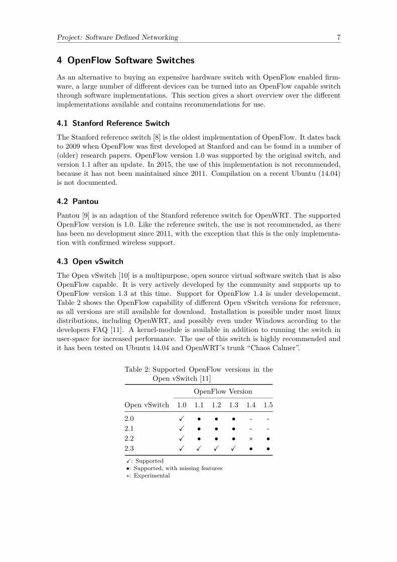
4.3 Open vSwitchThe Open vSwitch [10] is a multipurpose, open source virtual software switch that is alsoOpenFlow capable. It is very actively developed by the community and supports up toOpenFlow version 1.3 at this time. Support for OpenFlow 1.4 is under developement.Table 2 shows the OpenFlow capability of different Open vSwitch versions for reference,as all versions are still available for download. Installation is possible under most linuxdistributions, including OpenWRT, and possibly even under Windows according to thedevelopers FAQ [11]. A kernel-module is available in addition to running the switch inuser-space for increased performance. The use of this switch is highly recommended andit has been tested on Ubuntu 14.04 and OpenWRT’s trunk “Chaos Calmer”.
Table 2: Supported OpenFlow versions in theOpen vSwitch [11]
OpenFlow Version
Open vSwitch 1.0 1.1 1.2 1.3 1.4 1.5
2.0 X • • • - -2.1 X • • • - -2.2 X • • • ∗ •2.3 X X X X • •X: Supported•: Supported, with missing features∗: Experimental

Project: Software Defined Networking 8
4.4 OFSoftswitchOFSoftswitch [12] is an OpenFlow software switch developed by the CPqD research in-stitute. It is based on an implementation from the Ericsson TrafficLab called Softswitch,which is in turn based on the Stanford reference switch. The supported OpenFlow versionis 1.3. There exists a version for linux in general and one for OpenWRT specifically. Theproject is still actively developed, but use is not fully recommended because there is verylittle documentation available and none of the reviewed papers actually uses this switch.
Project: Software Defined Networking 9
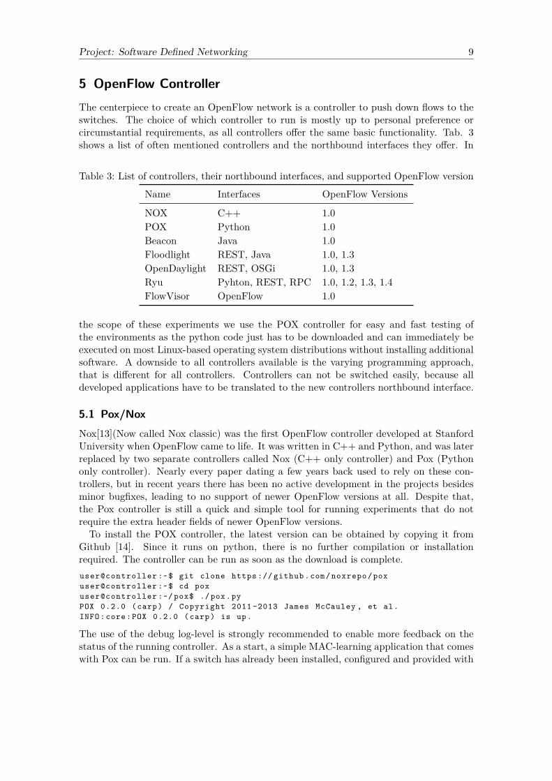
5 OpenFlow ControllerThe centerpiece to create an OpenFlow network is a controller to push down flows to theswitches. The choice of which controller to run is mostly up to personal preference orcircumstantial requirements, as all controllers offer the same basic functionality. Tab. 3shows a list of often mentioned controllers and the northbound interfaces they offer. In
Table 3: List of controllers, their northbound interfaces, and supported OpenFlow version
Name Interfaces OpenFlow Versions
NOX C++ 1.0POX Python 1.0Beacon Java 1.0Floodlight REST, Java 1.0, 1.3OpenDaylight REST, OSGi 1.0, 1.3Ryu Pyhton, REST, RPC 1.0, 1.2, 1.3, 1.4FlowVisor OpenFlow 1.0
the scope of these experiments we use the POX controller for easy and fast testing ofthe environments as the python code just has to be downloaded and can immediately beexecuted on most Linux-based operating system distributions without installing additionalsoftware. A downside to all controllers available is the varying programming approach,that is different for all controllers. Controllers can not be switched easily, because alldeveloped applications have to be translated to the new controllers northbound interface.
5.1 Pox/NoxNox[13](Now called Nox classic) was the first OpenFlow controller developed at StanfordUniversity when OpenFlow came to life. It was written in C++ and Python, and was laterreplaced by two separate controllers called Nox (C++ only controller) and Pox (Pythononly controller). Nearly every paper dating a few years back used to rely on these con-trollers, but in recent years there has been no active development in the projects besidesminor bugfixes, leading to no support of newer OpenFlow versions at all. Despite that,the Pox controller is still a quick and simple tool for running experiments that do notrequire the extra header fields of newer OpenFlow versions.To install the POX controller, the latest version can be obtained by copying it from
Github [14]. Since it runs on python, there is no further compilation or installationrequired. The controller can be run as soon as the download is complete.user@controller :~$ git clone https :// github .com/ noxrepo /poxuser@controller :~$ cd poxuser@controller :~/ pox$ ./ pox.pyPOX 0.2.0 (carp) / Copyright 2011 -2013 James McCauley , et al.INFO:core:POX 0.2.0 (carp) is up.
The use of the debug log-level is strongly recommended to enable more feedback on thestatus of the running controller. As a start, a simple MAC-learning application that comeswith Pox can be run. If a switch has already been installed, configured and provided with

Project: Software Defined Networking 10
the right IP address for the controller (section 6.3), the controller receives the connectionattempt as soon as he is up.user@controller :~/ pox$ ./ pox.py log.level --DEBUG forwarding . l2_learningPOX 0.2.0 (carp) / Copyright 2011 -2013 James McCauley , et al.DEBUG:core:POX 0.2.0 (carp) going up ...DEBUG:core: Running on CPython (2.7.6/ Mar 22 2014 22:59:56)DEBUG:core: Platform Linux -3.13.0 -32 - generic -x86_64 -Ubuntu -14.04 - trustyINFO:core:POX 0.2.0 (carp) is up.DEBUG: openflow .of_01: Listening on 0.0.0.0:6633INFO: openflow .of_01 :[00 -50 -56 -98 -1a-ab 1] connected
5.2 BeaconBeacon[15] is a Java based controller that is closely connected to the Eclipse developmentenvironment (meaning it is required to develop applications). It is actively developed byStanford University and a community and offers basic modules for topology discovery,learning switch, or routing. Being written in Java and well integrated into Eclipse, theController and it’s applications are by no means lightweight.
5.3 FloodlightFloodlight [16] is a fork of the Beacon controller by BigSwitch Networks. It offers advancedfeatures over the original code basis like handling topologies with loops, a web-based GUI,and support for newer OpenFlow versions. Because the main northbound interface isa REST-API, there is no definite programming language for applications, making theapproach very versatile.
5.4 OpenDaylightThe OpenDaylight[17] project introduces are more general approach to a controller. Itis not fixed on OpenFlow as the only southbound interface. instead, modules can bedynamically added. The scope of southbound interfaces covers protocols like NETCONF,LISP, PCEP and SNMP. Like the Floodlight controller, OpenDaylight offers a RESTinterface as a general way of interacting with the controller. It is very actively developedand backed by the Linux Foundation and Cisco.
5.5 RyuRyu[18] is a component-based, flexible controller written in python. It’s specialty is thebroad support of OpenFlow versions, and the ability to create new northbound inter-faces via RPC mechanisms. Also, Ryu support alternative southbound interfaces, like theNETCONF or SNMP protocols. Own applications can make use of a variety of built-inmodules to, for example, gather topology information or implement a firewall.
5.6 FlowVisorThe FlowVisor[19] is a special purpose controller developed at Stanford. It acts like atransparent proxy between OpenFlow controlled switches and other controllers. It createsso called “slices” in the network traffic, where each slice is controlled by one controller

Project: Software Defined Networking 11
exclusively. These slices are defined like flow rules: A combination of different OpenFlow1.0 protocol fields, like switch port, IP or ethernet address, or TCP/UDP ports.

Project: Software Defined Networking 12
6 OpenFlow on Virtual MachinesThis experiment aims to give an understanding of the basic setup, configuration andfunction of an OpenFlow enabled network by deploying the Open vSwitch in a simplevirtual environment. The OpenFlow functionality of the vSwitch can be controlled byan OpenFlow controller via the OpenFlow protocol, thus representing the characteristicOpenFlow-architecture as shown in section 3. To that end, a flexible, virtual testingenvironment is created, based on VMware’s virtualization technology.
6.1 Hardware/Software
Hardware
• ESXi Server 5.5
Software
• vSphere Webclient
• Ubuntu Server 14.04.1 64 bit
• Open vSwitch 2.3.1
• Pox ControllerThe virtual machines are deployed on a VMware ESXi-server with the configuration
shown in tab. 4, although the experiment could be run on a workstation as well. Theconfiguration of the virtual environment is conducted via the vSphere Webclient, the onlyVMware configuration tool that supports all features. In general, it can not be accessedfrom a Linux operating system, because a recent version of the Adobe Flash player isneeded, which is discontinued under Linux. As a workaround, the Google Chrome browserwith it’s integrated Flash implementation can be used.All virtual machines (hosts and switches) run the Ubuntu Server 14.04.1 64 bit operat-
ing system. Although almost any Unix-like operating system could be used, one without agraphical user interface is preferred in order to reduce complexity and resource consump-tion. The virtual machines that act as OpenFlow switches run the self-compiled OpenvSwitch 2.3.
Table 4: Configuration of the ESXi Server
Property Configuration
Model Supermicro X8DT3CPU 8 x 2,4 GHz Xeon E5620RAM 64 GBVM Hypervisor vSphere v5.5.0, Build 1623101
6.2 InstallationAn OpenFlow enabled switch is needed as the centerpiece of the virtual networking en-vironment. To that end, the virtual Open vSwitch [10] is deployed on a VM, taking overthe switching functionality of the Linux kernel on layer 2 of the ISO-OSI reference model.The software is available as precompiled packages in the Ubuntu 14.04 repository, but

Project: Software Defined Networking 13
only in a rather outdated version (2.0.1). Installation through the package managementis as simple as:root@ovs :~# apt -get install openvswitch - common
A short test revealed that the version installed this way is indeed fully operational, butwith the constraints that come with the version, for example the limited support of newerOpenFlow versions as shown in section 4. In the following, we use the self-compiled version2.3.0. It is available via Github [20] or the Open vSwitch project website [10].The installation steps shown below comply with the documentation in the extensive FAQ
on the Open vSwitch Github repository [20]. First, all dependencies needed to compileand run the Open vSwitch have to be installed:root@ovs :~# apt -get install python - simplejson python -qt4 libssl -dev \
python -twisted -conch automake autoconf gcc uml - utilities libtool \build - essential pkg - config linux -headers -$(uname -r) git
The most recent version of the source code can be obtained by using git.root@ovs :~# git clone https :// github .com/ openvswitch /ovs/root@ovs :~# cd ovs
After descending into the new directory, the vSwitch is compiled and installed by enteringroot@ovs :~/ ovs# ./ boot.shroot@ovs :~/ ovs# ./ configure --with -linux =/ lib/ modules /$(uname -r)/ buildroot@ovs :~/ ovs# makeroot@ovs :~/ ovs# make install
The use of the --with-linux switch is optional but recommended, as it generates a kernelmodule. Contrary to running the vSwitch in user space, the kernel module offers enhancedperformance, but is only available in Linux. The kernel module can be loaded by entering:root@ovs :~/ ovs# cd datapath /linux/root@ovs :~/ ovs/ datapath /linux# modprobe openvswitchroot@ovs :~/ ovs# cd ../../
Alternatively, the module can be integrated more permanently into the system by copyingthe module into the default directory and enable it on every system start automatically.root@ovs :~/ ovs# cp datapath /linux/ openvswitch .ko /lib/ modules /$(uname -r)/root@ovs :~/ ovs# depmod -aroot@ovs :~/ ovs# modprobe openvswitchroot@ovs :~/ ovs# echo " openvswitch " >> /etc/ modules
To complete the installation, two configuration files need to be created. On the one hand,the configuration file for the vSwitch daemon (ovs-vswitchd), and on the other the databasethat contains the switch configuration (ovsdb-server), for example which interfaces areconnected to a virtual switch.root@ovs :~/ ovs# touch /usr/local/etc/ovs - vswitchd .confroot@ovs :~/ ovs# mkdir -p /usr/local/etc/ openvswitchroot@ovs :~/ ovs# ovsdb -tool create /usr/local/etc/ openvswitch /conf.db \
vswitchd / vswitch . ovsschema
These files do not contain any content at first, because they are filled automatically and canbe altered through the Open vSwitch command line tools. At last, a start script is createdthat simplifies the process of bringing the vSwitch daemon up. The lines beginning with–private-key, –certificate and –bootstrap-ca-cert can be omitted if there is no SSL supportneeded.

Project: Software Defined Networking 14
#!/ bin/bashovsdb - server --remote =punix :/ usr/local/var/run/ openvswitch /db.sock \
--remote =db: Open_vSwitch , Open_vSwitch , manager_options \--private -key=db: Open_vSwitch ,SSL , private_key \--certificate =db: Open_vSwitch ,SSL , certificate \--bootstrap -ca -cert=db: Open_vSwitch ,SSL , ca_cert \--pidfile --detach
ovs -vsctl --no -wait initovs - vswitchd --pidfile --detachovs -vsctl show
After running the script, if the installation was a success, the script shows the output fromit’s last command. It should contain the ID of the first, automatically created datapath, astructure in the kernel module that represents a virtual switch:2d3f70ad -6433 -4008 -8759 -29 dd088bc63b
Check if the components are running.root@ovs :~# ps -e | grep ovs
1279 ? 00:01:51 ovsdb - server1282 ? 00:23:44 ovs - vswitchd
Now the installation process is completed. The steps to reactivate the Open vSwitch aftera reboot are
• loading the kernel module (if not loaded automatically as shown above)
• running the start script.
Of course, this procedure can be automated by, for example, adding it to the /etc/rc.localfile (possibly with a delay because the networking needs to be up before running thescript).
6.3 ConfigurationOpen vSwitch
Without any further configuration the vSwitch has no function at all. There are fourcommand-line programs to set up and query the Open vSwitch. Each of them has aman-page, where additional information can be found.
ovs-vsctl Configures the ovs-vswitchd by representing a high-level interface to the con-figuration database. Connects to the ovsdb-server process to query and update theconfiguration according to the passed parameters.
ovs-ofctl Communicates with the OpenFlow part of the virtual switch showing the currentstate, features and administrating flow table entries. Because the OpenFlow protocolis standardized, this command should work with any OpenFlow enabled Switch.
ovs-appctl Tool for querying the vSwitch daemon, mostly used for logging. This is theonly tool to dump hidden flows (see section 6.5).
ovs-dpctl Manages flow table entries on the level of the kernel-based datapaths. Requiresthe kernel module to be used. If the ovs-vswitchd is used, as in this case, the man-page advises the use of ovs-vsctl instead.

Project: Software Defined Networking 15
Figure 4: Configuration of the Open vSwitch
The first command (ovs-vsctl) is the most important one for configuring and managingthe switch. In general, the concept for setting up the vSwitch is creating a bridge betweenall interfaces of one device that are participating in the OpenFlow managed network. Thebehaviour of this bridge is then determined by the given flow rules. For this experiment, aVM is set up as shown in figure 4. In addition to the OpenFlow managed interfaces eth1and eth2, a separate configuration interface (eth0) is created. This way, if configuring theVM via SSH, there is always a reliable connection that is not influenced by setting upthe Open vSwitch, providing a more comfortable basis for experimenting with differentsettings.The following steps are inspired by the very extensive FAQ in the Open vSwitch Github
repository [11]. First, the virtual bridge has to be created, automatically generating avirtual bridge interface with the same name as the bridge. More interfaces are added tothis bridge as needed:root@ovs :~# ovs -vsctl add -br br0root@ovs :~# ovs -vsctl add -port br0 eth1root@ovs :~# ovs -vsctl add -port br0 eth2
Now the interfaces, including the bridge interface, are being set up. To that end, thebridge interface br0 is assigned an IP address, while the attached interfaces eth1 and eth2are stripped of their configuration, ensuring they are up. At this point at the latest, theadditional configuration interface comes in handy. As the bridged interfaces are strippedof their functionality, the ability to access the machine through them is disrupted, makingphysical access to the machine necessary (or via the vSphere Webclient in this case).root@ovs :~# ifconfig br0 192.168.1.11 netmask 255.255.255.0 uproot@ovs :~# ifconfig eth1 0 uproot@ovs :~# ifconfig eth2 0 up
For these settings to be permanent they can be written to the /etc/network/interfacesfile.# /etc/ network / interfacesiface br0 inet static
Project: Software Defined Networking 16
address 192.168.1.11netmask 255.255.255.0
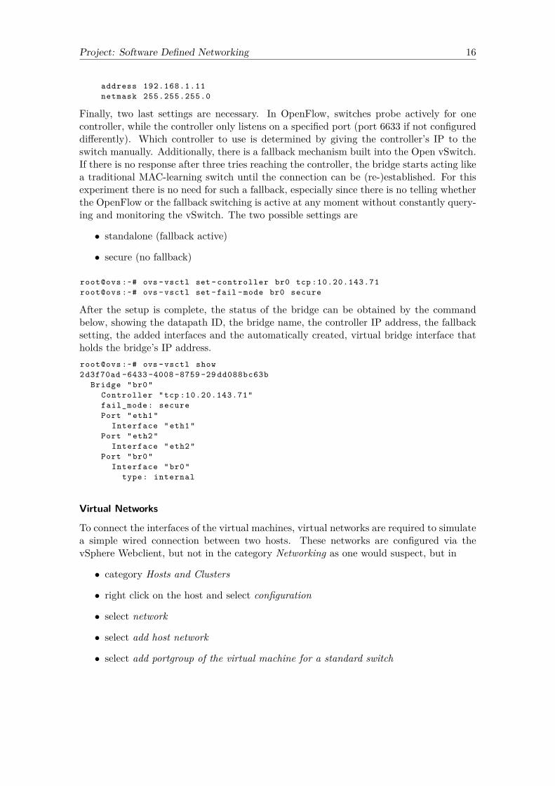
Finally, two last settings are necessary. In OpenFlow, switches probe actively for onecontroller, while the controller only listens on a specified port (port 6633 if not configureddifferently). Which controller to use is determined by giving the controller’s IP to theswitch manually. Additionally, there is a fallback mechanism built into the Open vSwitch.If there is no response after three tries reaching the controller, the bridge starts acting likea traditional MAC-learning switch until the connection can be (re-)established. For thisexperiment there is no need for such a fallback, especially since there is no telling whetherthe OpenFlow or the fallback switching is active at any moment without constantly query-ing and monitoring the vSwitch. The two possible settings are
• standalone (fallback active)
• secure (no fallback)
root@ovs :~# ovs -vsctl set - controller br0 tcp :10.20.143.71root@ovs :~# ovs -vsctl set -fail -mode br0 secure
After the setup is complete, the status of the bridge can be obtained by the commandbelow, showing the datapath ID, the bridge name, the controller IP address, the fallbacksetting, the added interfaces and the automatically created, virtual bridge interface thatholds the bridge’s IP address.root@ovs :~# ovs -vsctl show2d3f70ad -6433 -4008 -8759 -29 dd088bc63b
Bridge "br0"Controller "tcp :10.20.143.71"fail_mode : securePort "eth1"
Interface "eth1"Port "eth2"
Interface "eth2"Port "br0"
Interface "br0"type: internal
Virtual Networks
To connect the interfaces of the virtual machines, virtual networks are required to simulatea simple wired connection between two hosts. These networks are configured via thevSphere Webclient, but not in the category Networking as one would suspect, but in
• category Hosts and Clusters
• right click on the host and select configuration
• select network
• select add host network
• select add portgroup of the virtual machine for a standard switch

Project: Software Defined Networking 17
These virtual networks are also called virtual switches. For every pair of interfaces thatare to be connected, one virtual switch has to be created. After that, the interfaces ofthe virtual machines can be connected to the newly created networks in their respectiveproperties.However, there is a Problem using these virtual networks and Open vSwitch: When
creating this experiment, the traffic over one virtual network was running without a prob-lem, while the traffic over a second, identically configured virtual network only worked inone direction. Figure 4 can be used to explain this unexpected behavior.As shown in the previous section, the vSwitch consists of a bridge br0 that has the other
interfaces attached to it. If a packet is sent from the bridge, for example to a host thatis connected to VM_Net1, an ARP-request with the source MAC-address of the virtualbridge interface br0 is sent out. This virtual interface does not have a MAC-address ofit’s own, but takes the address of one of the interfaces that are attached to it instead. Inthis case it took the MAC-address of eth1. The ARP-request is broadcasted through thevirtual network to the host. ARP-replies from the host are directed at the MAC-address ofbr0 (= eth1) and delivered to the eth1 interface by the virtual network without a problem.Now, a packet is sent through the bridge to a host behind VM_Net2. Again, the ARP-
request has the source MAC-address of br0, which is in fact the address of eth1. Thevirtual network broadcasts this ARP-request to the host. An ARP-reply is sent out fromthe host to the MAC-address of br0. VM_Net2 does not forward the packet to eth2.In contrast to the assumption that the virtual networks would behave like a traditional
switch, there are important differences which cause this behavior. The network only hasknowledge of MAC-addresses of VMs that have been added directly to it in VMware. Thereis no capability of learning about new MAC-addresses that are not directly connected.In the first case, the MAC-address for the host to reply to (br0) is the same address that
is directly connected to the virtual network (eth1). In the second case, the MAC-addressthe host has to reply to (br0) is not directly connected to the virtual network, causing theARP-reply to get dropped by the network. This problem will not occur specifically whenusing Open vSwitch, but every time a VM acts as a layer 2 forwarding device.As a workaround, the virtual networks can be set to promiscious mode using the fol-
lowing steps, causing them to forward every incoming packet to every VM connected toit. This behavior is similar to a simple hub.
• category Hosts and Clusters
• right click on the host and select configuration
• select network
• select the respective network and click modify configuration
• select security and set promiscious mode to accept
6.4 Test SetupIn the final version of this experiment two hosts can communicate through a network ofOpenFlow controlled switches. To start with the smallest configuration possible, the setupdepicted in figure 5 is created.VM_Net1 connects Host1 to the vSwitch, whereas VM_Net2 connects the vSwitch to
Host2. Additionally, all virtual machines are connected to the network VM_Net3. This

Project: Software Defined Networking 18
Figure 5: Virtual Test Setup with Out-of-Band Controller
Network is used for configuration and monitoring purposes only, and it is not part of theOpenFlow controlled networking. It is possible to attach the controller to this out-of-bandnetwork, details in this regard are explained in section 6.5. A SSH-server is installed on allvirtual machines and is reachable via VM_Net3 to maintain a connection to all devices thatis independent from the OpenFlow controlled network. This enables the configuration of allOpenFlow related interfaces without shutting down the own connection. Furthermore, thisnetwork provides internet access for all virtual machines via the university network, andallows downloading additional packages and software as needed. While the IP addressesin the OpenFlow network are set up manually, the configuration network uses an existingDHCP server.To do a quick test of the environment, a SSH session to both Host1 and the controller
is established. When trying to ping from Host1 to Host2, the command will return noanswer. The packets are relayed to the OpenFlow switch, but because there is no rulepresent for this traffic flow and the controller is not up to be queried, the packets aredropped.In the next step, the pox controller is started on the controller VM with the l2_learning
module enabled, setting the switch’s behavior to a layer 2 learning switch.user@controller :~/ pox$ ./ pox.py forwarding . l2_learning
After a few seconds, there should be a message saying a switch connected to the controller.If the ping command is still in progress, the pings will be able to get through after a fewmore seconds. In case the debug level logging is enabled in pox (see section 5), the flowspushed down to the switch are visible on stdout on the controller VM.From this point on, expanding the test setup is easy: More VMs configured as OpenFlow
enabled switches can be added as needed in any setup necessary by copying the first switchVM and changing the bridge’s IP. In a quick test, the controller was able to supervise atleast 20 switches at the same time.
6.5 In-Band vs. Out-of-BandThe previous setup had the controller attached to a separate network, that is not partof the OpenFlow management. This is called an out-of-band controller. Alternatively, itis possible to include the controller in-band, as part of the OpenFlow managed network.
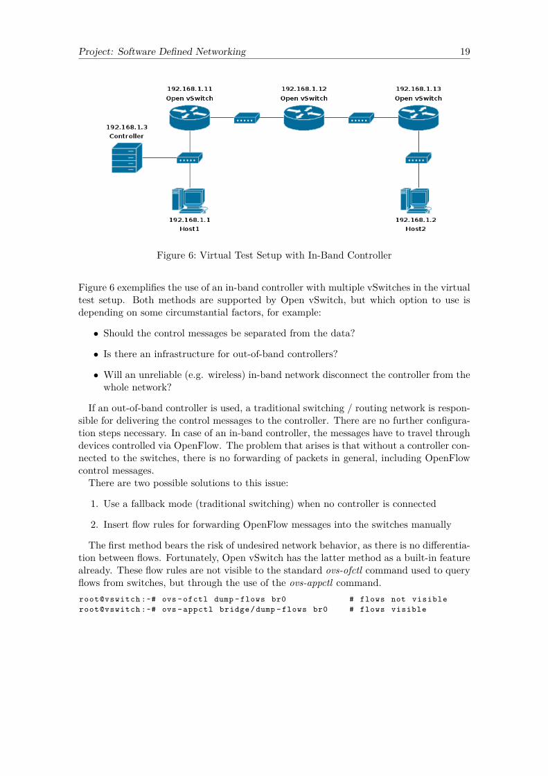
Project: Software Defined Networking 19
Figure 6: Virtual Test Setup with In-Band Controller
Figure 6 exemplifies the use of an in-band controller with multiple vSwitches in the virtualtest setup. Both methods are supported by Open vSwitch, but which option to use isdepending on some circumstantial factors, for example:
• Should the control messages be separated from the data?
• Is there an infrastructure for out-of-band controllers?
• Will an unreliable (e.g. wireless) in-band network disconnect the controller from thewhole network?
If an out-of-band controller is used, a traditional switching / routing network is respon-sible for delivering the control messages to the controller. There are no further configura-tion steps necessary. In case of an in-band controller, the messages have to travel throughdevices controlled via OpenFlow. The problem that arises is that without a controller con-nected to the switches, there is no forwarding of packets in general, including OpenFlowcontrol messages.There are two possible solutions to this issue:
1. Use a fallback mode (traditional switching) when no controller is connected
2. Insert flow rules for forwarding OpenFlow messages into the switches manually
The first method bears the risk of undesired network behavior, as there is no differentia-tion between flows. Fortunately, Open vSwitch has the latter method as a built-in featurealready. These flow rules are not visible to the standard ovs-ofctl command used to queryflows from switches, but through the use of the ovs-appctl command.root@vswitch :~# ovs -ofctl dump -flows br0 # flows not visibleroot@vswitch :~# ovs - appctl bridge /dump -flows br0 # flows visible

Project: Software Defined Networking 20
7 OpenFlow on Raspberry PiA Raspberry Pi can be used instead of designated networking hardware to test and examineOpenFlow functionality. To this end, this section describes how to install and configurethe needed software on a Raspberry Pi with additional network interfaces. In a short test,the performance of this setup is tested.
7.1 Hardware/Software
Hardware
• Raspberry Pi Model B+
• Speed Dragon USB 2.0 10/100MbpsEthernet Adapter Model: UNW01
Software
• Raspbian Wheezy (January 2014)Kernel 3.12.35
• Open vSwitch 2.3.1
• Pox Controller
Basis is the Raspberry Pi Model B+ with it’s 4 USB interfaces which allow for upto 4 additional Ethernet interfaces via USB-to-Ethernet adapters. The Raspberry Pi isdriven by the Raspbian operating system in the version January 2014. As a Debian-based operating system, it is possible to install the Open vSwitch similar to the virtualenvironment. The Pox controller is used to manage the vSwitch from either locally on theRaspberry Pi or on a remote machine.
7.2 InstallationOpen vSwitch
The Raspbian operating system is installed on a micro-SD card via the dd command.user@pc :~$ dd if =2014 -12 -15 - raspbian - wheezy .img of=/ dev/ mmcblk0 bs=4M
After booting into textmode, the first step is to install the Open vSwitch. In contrastto Ubuntu, there is no precompiled package available via apt-get. The source code forcompiling Open vSwitch can be obtained from the Github repository as show in section6.2, or downloaded from the project’s website via wget.pi@raspi :~$ wget http :// openvswitch .org/ releases / openvswitch -2.3.1. tar.gzpi@raspi :~$ tar -xvzf openvswitch -2.3.1. tar.gzpi@raspi :~$ cd openvswitch -2.3.1
Before compilation, the build dependencies have to be installed.pi@raspi :~$ sudo suroot@raspi :~# apt -get updateroo@raspi :~# apt -get install python - simplejson python -qt4 libssl -dev \
python -twisted -conch automake autoconf gcc uml - utilities libtool \build - essential pkg - config
A problem is choosing the right kernel header files for the compilation of the kernel module.There is no exact match for the kernel version in use. The correct package to install forkernel 3.12.35 isroot@raspi :~# apt -get install linux -headers -3.12 -1 - rpi

Project: Software Defined Networking 21
The compilation itself is similar to the one in the virtual environment, but choosing thepreviously installed kernel header for compiling the Open vSwitch kernel module.root@raspi :~# cd openvswitch -2.3.1root@raspi :~/ openvswitch -2.3.1# ./ bootroot@raspi :~/ openvswitch -2.3.1# ./ configure --with -linux =\
/lib/ modules /3.12 -1 - rpi/buildroot@raspi :~/ openvswitch -2.3.1# ./ makeroot@raspi :~/ openvswitch -2.3.1# ./ make install
After these steps are completed, the kernel module needs to be loaded and the configurationfiles are beeing set up. This is analog to the setup on Ubuntu described in section 6.2,including the start script for the vSwitch.
USB-to-Ethernet Adapter
The USB-to-ethernet adapter mentioned above works out of the box, without installingadditional software or drivers on the used Raspbian operating system and kernel verison.For a more reliable mapping of the interfaces to the device name, a rule is created in the/etc/udev/rules.d/70-persistent-net.rules file for each adapter.# USB to ethernet adapter ( MOSCHIP usb - ethernet driver ) -> eth1SUBSYSTEM ==" net", ACTION ==" add", DRIVERS =="?*" ,ATTR{ address }=="00:13:3 b :99:03: f2", ATTR{ dev_id }=="0 x0", ATTR{type }=="1" ,KERNEL ==" eth *", NAME =" eth1"
# USB to ethernet adapter ( MOSCHIP usb - ethernet driver ) -> eth2SUBSYSTEM ==" net", ACTION ==" add", DRIVERS =="?*" ,ATTR{ address }=="00:13:3 b :99:04:2 a", ATTR{ dev_id }=="0 x0", ATTR{type }=="1" ,KERNEL ==" eth *", NAME =" eth2"
This configuration is specific to the Raspberry Pi, because there are detachable interfaces.In the virtual environment or on OpenWrt, interfaces will not change their device namewithout changing the configuration.
7.3 ConfigurationThe configuration of the Open vSwitch is exactly the same as shown in section 6.3. It islisted briefly for reference:# add the ovs - bridgeroot@raspi :~# ovs -vsctl add -br br0
# add the interfaces to the bridgeroot@raspi :~# ovs -vsctl add -port br0 eth0root@raspi :~# ovs -vsctl add -port br0 eth1root@raspi :~# ovs -vsctl add -port br0 eth2
# configure the interfaces# use /etc/ network / interfaces for permanent configurationroot@raspi :~# ifconfig br0 192.168.1.11 netmask 255.255.255.0 uproot@raspi :~# ifconfig eth0 0 uproot@raspi :~# ifconfig eth1 0 uproot@raspi :~# ifconfig eth2 0 up
# set the controller address and fallback moderoot@raspi :~# ovs -vsctl set - controller br0 tcp :192.168.1.10root@raspi :~# ovs -vsctl set -fail -mode br0 secure

Project: Software Defined Networking 22
Figure 7: OpenFlow enabled Raspberry Pi with additional USB to LAN interfaces
7.4 Test SetupThe test setup for the OpenFlow enabled Raspberry Pi consists of two host PCs, connectedto the USB-to-ethernet interfaces, and an external Pox controller on a third PC, connectedto the on-board interface (figure 7). The goal of this test is to determine if the RaspberryPi offers enough performance to run the installed Open vSwitch.To test the throughput, the Iperf command is run between the two hosts for 30 seconds
to allow for flow rules to be placed by the controller without influencing the average valuestoo much. The results are shown in table 5. A first test failed with very low transmissionspeeds of about 25 Mbit/s for TCP and about 55 Mbit/s for UDP. At the same time theCPU load was at maximum capacity. The reason for this was a misconfiguration whencompiling without the appropriate kernel headers. There was no kernel module createdand the switch was running in user space.But even with the kernel module in place, the performance is only at 70 Mbit/s for TCP
and 90 Mbit/s for UDP, while the CPU load remains at high levels. While this test onlyused one traffic flow, performance is to be expected even lower when deployed in a largernetwork with concurrent traffic streams.In conclusion, the Raspberry Pi model B+ is not fit for using it with Open vSwitch. The
CPU is not fast enough to handle the incoming traffic, including the Open vSwitch andOpenFlow overhead. A possible solution could be to exchange the Raspberry Pi B+ forthe recently introduced Raspberry Pi 2, which offers enhanced computation capabilities.

Project: Software Defined Networking 23
Table 5: Average Iperf performance running Open vSwitch
Transmission speed [Mbit/s] CPU load [%]
Protcol no kmod with kmod no kmod with kmod
TCP 25 70 99 90UDP 55 90 99 80
kmod: Open vSwitch kernel module

Project: Software Defined Networking 24
8 OpenFlow on OpenWRTOpenWrt enhances consumer-grade networking hardware with full access to the systemand the possibility to add additional capabilities. This includes installing Open vSwitchand turning devices supported by OpenWrt into OpenFlow capable switches. This sectiongives an introduction to installing and configuring Open vSwitch on OpenWrt and presentsa testbed for experimentation and to showcase OpenFlow capabilities.
8.1 Hardware/Software
Hardware
• TP-Link WDR3600
• Raspberry Pi Model B+
Software
• OpenWRT Trunk “Chaos Calmer”
• Open vSwitch for OpenWRT
• Pox Controller
• Ubuntu 14.04.1The router model TP-Link WDR3600 is used in this setup. It is well supported by
OpenWrt and offers 5 ethernet interfaces to use for OpenFlow controlled networking. Amost recent OpenWrt version is installed on every switch from the development trunk.The controller runs on a Raspberry Pi. For cross-compiling the needed OpenWrt versionwith Open vSwitch support, a Workstation with Ubuntu 14.04.1 is used.
8.2 InstallationOpenWrt
It is important to note that the required version of OpenWrt has to come from the develop-ment trunk. There is no Open vSwitch package in the last official release Barrier Braker.There are two possible ways to get an appropriate OpenWrt image for the WDR3600:
1. Download a trunk snapshot from [21], which is created every day, and install theOpen vSwitch package via the opkg package management system.
2. Download the trunk source code via Subversion and compile OpenWrt after choosingthe Open vSwitch package in the menuconfig.
The first option was working fine at first, but in newer snapshots it is impossible to installOpen vSwitch due to unsatisfied dependencies. The exact error message isCollected errors :
* satisfy_dependencies_for : Cannot satisfy the following* dependencies for openvswitch :* kmod - udptunnel4 * kmod - udptunnel6 ** opkg_install_cmd : Cannot install package openvswitch .
The needed dependencies are no longer in the extra packages called feeds. A bug reportthrough the OpenWrt bug reporting system was closed without comment.Fortunately, the self-compiled image still works, indicating that the missing dependen-
cies are not needed in the first place. Before compiling, the build dependencies have to beinstalled on the Ubuntu machine.

Project: Software Defined Networking 25
user@pc :~$ sudo apt -get install gccg ++ binutils patch bzip2 flex \bison make autoconf gettext unzip subversion libncurses5 -dev \ncurses -term zlib1g -dev gawk git -core libz -dev
After that, the trunk source code can be downloaded via Subversion. Additionally thefeeds packages, which include Open vSwitch, have to be downloaded and integrated intothe trunk source code. This can be done through a script that is already in the sourcefiles.user@pc :~$ svn co svn :// svn. openwrt .org/ openwrt /trunk trunkuser@pc :~$ cd trunkuser@pc :~$ ./ scripts /feeds update -auser@pc :~$ ./ scripts /feeds install -a
Now, the settings for compiling the image have to be made.user@pc :~$ make menuconfig
In the opening menu, first choose the target system and device OpenWrt will be installedon, in this case the values are:
• Target System: Atheros (ar7xxx/ar9xxx)
• Subtarget: Generic
• Target Profile: TP-Link TL-WDR3500/3600/4300/4310/MW4350R
To compile Open vSwitch into the image, two more packages have to be selected. TheOpen vSwitch main package and the additional kernel module. They have to selected withan “*” symbol, and not with “M”, as in manual installation, else the installation will notbe possible afterwards because of the missing dependencies.
• Network → openvswitch
• Kernel Modules → Network Support → kmod-openvswitch
The compilation can be started after exiting and saving the menuconfig. To do that, enteruser@pc :~$ make V=99
for maximum verbosity in case an error occurs when compiling. If the compilation wassuccessful, the image files can be found in the trunk/bin/ar7xxx/ directory. The filenameshould look like this:openwrt -ar71xx -generic -tl -wdr3600 -squashfs - factory .bin
For flashing, it is advisable to only use the factory images, which create a clean installationon the device. The sysupgrade files only come in handy when the configuration on thedevice has to stay intact. In case the original vendor-issued firmware is still installed, theeasiest way to install the newly compiled image is to connect via the webinterface andchoose the factory file as a system upgrade.If there is an older OpenWrt firmware installed already, the following set of commands
has proven to be useful (not only when changing from original firmware to OpenWrt, butalso to start with a clean, up to date installation). An important detail to note is, thatthe /tmp directory is in fact mounted into RAM. Else there would not be enough memoryfor the image file.
Project: Software Defined Networking 26
root@openwrt :~# cd /tmproot@openwrt :/ tmp# scp user@workstation :~/ openwrt - factory .bin ./root@openwrt :/ tmp# mtd -r write openwrt - factory .bin firmware
There is no Webinterface installed, so after the device reboots it can be accessed via telneton 192.168.1.1. After setting a password (passwd command) for root, the device is onlyaccessible via SSH and the telnet service is deactivated.
Open vSwitch
When it was possible to install Open vSwitch on the trunk snapshot, and after flashingthe downloaded image as shown above, only the following commands were necessary:root@openwrt :~# opkg updateroot@openwrt :~# opkg install openvswitch kmod - openvswitchroot@openwrt :~# reboot
Of course, these commands require a working internet connection on the device. To achievethis with the default configuration, the WAN port of the device is connected to a networkwith a working DHCP server and internet access.
8.3 ConfigurationOpenWRT
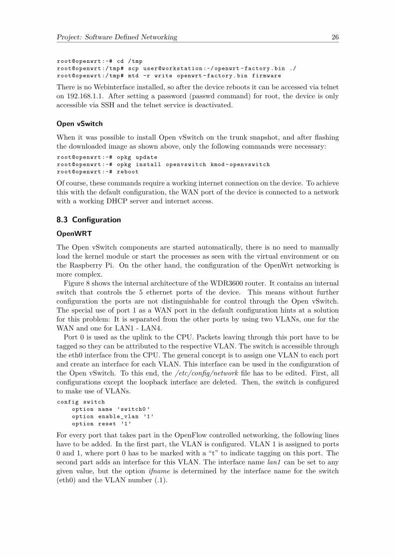
The Open vSwitch components are started automatically, there is no need to manuallyload the kernel module or start the processes as seen with the virtual environment or onthe Raspberry Pi. On the other hand, the configuration of the OpenWrt networking ismore complex.Figure 8 shows the internal architecture of the WDR3600 router. It contains an internal
switch that controls the 5 ethernet ports of the device. This means without furtherconfiguration the ports are not distinguishable for control through the Open vSwitch.The special use of port 1 as a WAN port in the default configuration hints at a solutionfor this problem: It is separated from the other ports by using two VLANs, one for theWAN and one for LAN1 - LAN4.Port 0 is used as the uplink to the CPU. Packets leaving through this port have to be
tagged so they can be attributed to the respective VLAN. The switch is accessible throughthe eth0 interface from the CPU. The general concept is to assign one VLAN to each portand create an interface for each VLAN. This interface can be used in the configuration ofthe Open vSwitch. To this end, the /etc/config/network file has to be edited. First, allconfigurations except the loopback interface are deleted. Then, the switch is configuredto make use of VLANs.config switch
option name ’switch0 ’option enable_vlan ’1’option reset ’1’
For every port that takes part in the OpenFlow controlled networking, the following lineshave to be added. In the first part, the VLAN is configured. VLAN 1 is assigned to ports0 and 1, where port 0 has to be marked with a “t” to indicate tagging on this port. Thesecond part adds an interface for this VLAN. The interface name lan1 can be set to anygiven value, but the option ifname is determined by the interface name for the switch(eth0) and the VLAN number (.1).

Project: Software Defined Networking 27
Figure 8: Internal architecture of the TP-Link WDR3600 internal switch
config switch_vlanoption device ’switch0 ’option vlan ’1’option ports ’0t 1’
config interface ’lan1 ’option ifname ’eth0 .1’option proto ’static ’
For the second port, the configuration lines look like this:config switch_vlan
option device ’switch0 ’option vlan ’2’option ports ’0t 2’
config interface ’lan2 ’option ifname ’eth0 .2’option proto ’static ’
At last, the Open vSwitch bridge, that is created in the next step, is configured with astatic IP address.config interface ’ovs ’
option ifname ’br0 ’option proto ’static ’option ipaddr ’192.168.1.11 ’option netmask ’255.255.255.0 ’
Open vSwitch
The Open vSwitch is configured as explained in section 6.3 and 7.3, with the interfacenames adjusted to match OpenWRT.# add the ovs - bridgeroot@openwrt :~# ovs -vsctl add -br br0

Project: Software Defined Networking 28
# add the interfaces to the bridgeroot@openwrt :~# ovs -vsctl add -port br0 eth0 .1root@openwrt :~# ovs -vsctl add -port br0 eth0 .2root@openwrt :~# ovs -vsctl add -port br0 eth0 .3root@openwrt :~# ovs -vsctl add -port br0 eth0 .4root@openwrt :~# ovs -vsctl add -port br0 eth0 .5
# set the controller address and fallback moderoot@openwrt :~# ovs -vsctl set - controller br0 tcp :192.168.1.10root@openwrt :~# ovs -vsctl set -fail -mode br0 secure
Open vSwitch not connecting to controller
When testing the newly installed and configured device after a reboot, the switch wouldnot connect to a controller. After checking the processes and configurations, there was nomistake noticeable. However, the switch started to work after changing a random settingin the Open vSwitch. The same behavior could be observed on all WDR3600 devices used.As a workaround for this bug, the following lines are added to the /etc/rc.local file. The
point is to set an arbitrary setting to another value, and in the next step to set it backto the original value. Setting a configuration with the same value it already has does nothave any effect.# workaround for openvswitchsleep 5ovs -vsctl set -fail -mode br0 standalonesleep 5ovs -vsctl set -fail -mode br0 secure
8.4 Test SetupAs a first test environment and to prove the viability of using Open vSwitch on OpenWrt,the setup in figure 9 is used. Two WDR3600 switches are connected via ethernet. Ahost is connected to each switch to generate and receive traffic in the network. A Rasp-berry Pi with Pox is connected to one of the switches in-band. Short tests with differentkinds of traffic (Iperf, TCP/UDP datatransfer, video streaming) showed no noticeableshortcomings.As a second, more permanent testbed the board in figure 10 was created. It consists
of 4 WDR3600 routers and 3 Raspberry Pis model B+. The WDR3600 routers serve asOpenFlow enabled switches, one Pi is configured as a controller, and the remaining twoRaspberry Pis represent hosts in the network. The wiring between the devices is depictedin figure 11. This board can be used in future OpenFlow experiments or demonstrations,for example to showcase failover mechanisms or flow-based “routing”.
8.5 Wireless InterfacesWireless interfaces can be added to the OpenFlow bridge as well. The testbed fromfigure 9 was used to confirm an OpenFlow controlled wireless connection between the twoWDR3600 routers. To this end, the devices are no longer connected by cable , but placesseveral meters apart.One drawback of the current OpenFlow protocol is that configuration of interfaces is
not implemented, only the flow tables can be influenced. This means there is no way

Project: Software Defined Networking 29
Figure 9: Testing environment with two WDR3600 OpenFlow-enabled devices and Rasp-berry Pi controller
Figure 10: OpenFlow on OpenWrt testbed with WDR3600 routers

Project: Software Defined Networking 30
Figure 11: Wiring of the OpenFlow on OpenWRT testbed
of programmatically configuring the wireless interface from within OpenFlow. For thisexperiment, the wireless interface was set up manually as an access point in the /etc/con-fig/wireless file.config wifi - device ’radio0 ’
option type ’mac80211 ’option hwmode ’11g’option path ’platform / ar934x_wmac ’option country ’DE ’option htmode ’HT20 ’option txpower ’10’option channel ’6’
config wifi -ifaceoption device ’radio0 ’option ssid ’OpenWrt ’option encryption ’none ’option mode ’ap ’
After that, the wireless interface is added to the OpenFlow controlled bridge like anyother interface.root@openwrt :~# ovs -vsctl add -port br0 radio0

Project: Software Defined Networking 31
9 ConclusionChapter 2 gave an overview over one SDN architecture, hinting at the fact that there is nodefinite standard to turn to. Chapter 3 described the OpenFlow protocol and architecture,including how packet forwarding is controlled through flows, flow tables and matchingfields. The software switches needed to form an OpenFlow controlled network, opposedto buying enterprise hardware, was described in chapter 4. Different controllers, softwarethat decides over how packets are handled on the switches, are presented in chapter 5.The first testing environment in chapter 6 showed how to install and configure normal
(virtual) hosts running the Ubuntu operating system as OpenFlow controlled switchesusing the Open vSwitch. The difference between in-band and out-of-band placement ofthe controller was explained. Overall, the virtual environment proved to be a very flexibleand viable basis for further experiments.Turning a Raspberry Pi into an OpenFlow controlled device, chapter 7 demonstrated
the process of installation and configuration, before testing the setup. Unfortunately, thecomputational power of the device was not high enough to support the packet forwardingthrough the Open vSwitch.Chapter 8 consisted of installing and configuring the OpenWRT firmware with Open-
Flow support on WDR3600 devices. The OpenWRT specific configuration proved to bemore complicated than in the previous chapters, including a bug that prevents the OpenvSwitch to function correctly after reboot. Despite that, once installed, the OpenWRTenvironment proved to be a reliable and cheap deployment for an OpenFlow enabled test-ing environment. As a result, the testbed in figure 10 was created for running futureexperiments.
Project: Software Defined Networking 32
Referenzen[1] Open Networking Foundation, “SDN architecture.” https://www.opennetworking.
org/images/stories/downloads/sdn-resources/technical-reports/TR_SDN_ARCH_1.0_06062014.pdf, 2014.
[2] E. Haleplidis, K. Pentikousis, S. Denazis, J. Hadi Salim, D. Meyer, andO. Koufopavlou, “Internet Draft: SDN Layers and Architecture Terminology.” https://tools.ietf.org/html/draft-irtf-sdnrg-layer-terminology-04, 2014.
[3] International Telecommunications Union, “Recommendation Y.3300: Frame-work of Software-Defined Networking.” http://www.itu.int/rec/T-REC-Y.3300-201406-I/en, 2014.
[4] E. Haleplidis, K. Pentikousis, S. Denazis, J. Hadi Salim, D. Meyer, andO. Koufopavlou, “SDN Layers and Architecture Terminology, Slides,” in IETF 88Meeting, IETF, 2014.
[5] Open Networking Foundation, “OpenFlow Switch Specification 1.4.0.”https://www.opennetworking.org/images/stories/downloads/sdn-resources/onf-specifications/openflow/openflow-spec-v1.4.0.pdf, 2013.
[6] “Stanford CS244 Wiki.” http://yuba.stanford.edu/cs244wiki/index.php/Overview.
[7] B. A. A. Nunes, M. Mendonca, X.-N. Nguyen, K. Obraczka, and T. Turletti, “ASurvey of Software-Defined Networking: Past, Present, and Future of ProgrammableNetworks,” IEEE Communications Surveys & Tutorials, vol. 16, no. 3, pp. 1617–1634,2013.
[8] “Stanford OpenFlow Reference Switch.” http://yuba.stanford.edu/git/gitweb.cgi?p=openflow.git;a=summary.
[9] “Pantou OpenFlow Switch.” http://archive.openflow.org/wk/index.php/Pantou_:_OpenFlow_1.0_for_OpenWRT.
[10] “Open vSwitch Homepage.” http://openvswitch.org.
[11] “Open vSwitch FAQ.” https://github.com/openvswitch/ovs/blob/master/FAQ.md.
[12] “CPqD OpenFlow Switch.” https://github.com/CPqD/ofsoftswitch13.
[13] “Nox/Pox Controller Website.” noxrepo.org.
[14] “POX Controller Github Repository.” https://github.com/noxrepo/pox.
[15] “Beacon Controller Website.” https://openflow.stanford.edu/display/Beacon/Home.
[16] “Floodlight Controller Website.” http://www.projectfloodlight.org/floodlight/.

Project: Software Defined Networking 33
[17] “OpenDaylight Controller Website.” http://www.opendaylight.org/.
[18] “Ryu Controller Website.” https://osrg.github.io/ryu/index.html.
[19] “Flowvisor Controller Website.” https://github.com/OPENNETWORKINGLAB/flowvisor/wiki.
[20] “Open vSwitch GitHub Repository.” https://github.com/openvswitch/ovs.
[21] “OpenWrt Trunk Snapshots.” https://downloads.openwrt.org/snapshots/trunk/.