psychrometrics - cryogenic industries … · psychrometrics ne of the key challenges associated...
TRANSCRIPT
A NEWSLETTER FROM CRYOGENIC INDUSTRIES WINTER 2012
Psychrometricsne of the key challenges associated with the use of ambient air as the heating medium for vaporization of cryogenic
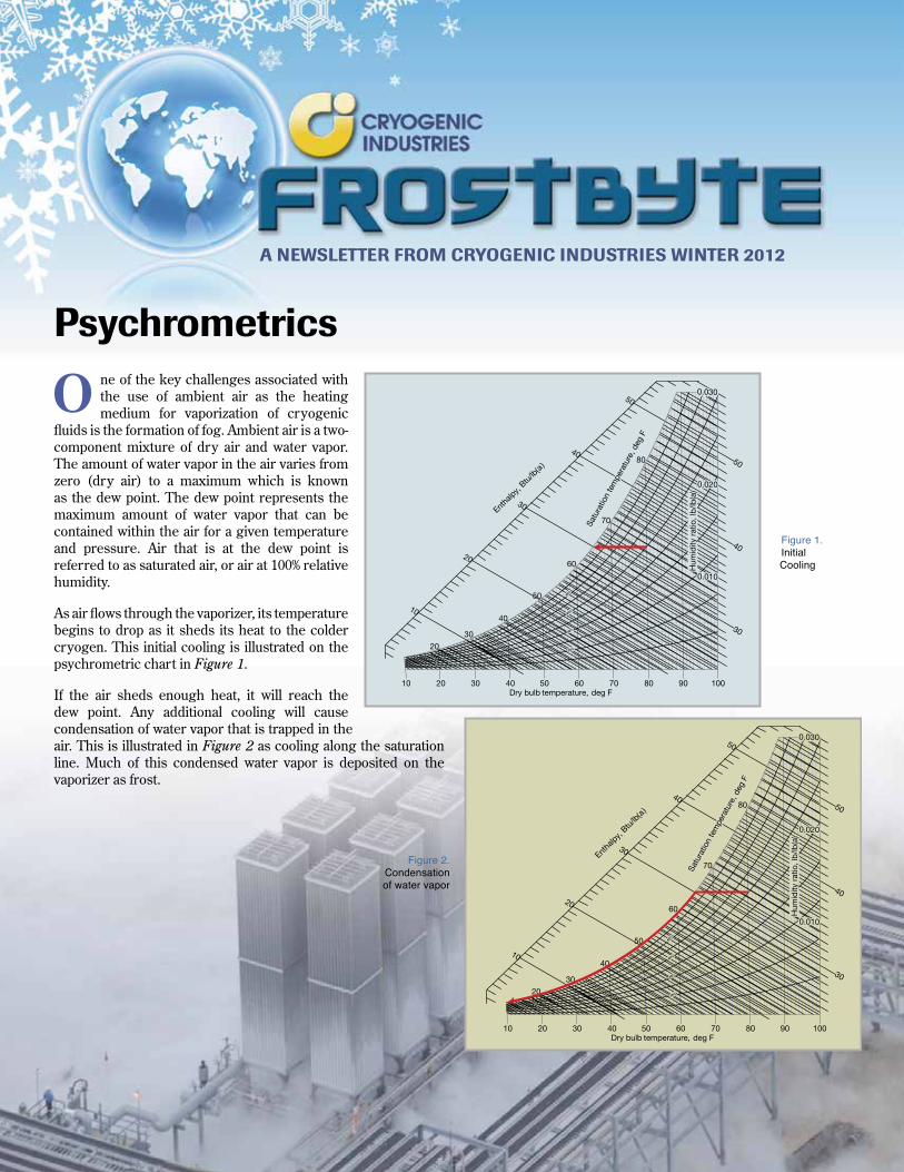
fluids is the formation of fog. Ambient air is a two-component mixture of dry air and water vapor. The amount of water vapor in the air varies from zero (dry air) to a maximum which is known as the dew point. The dew point represents the maximum amount of water vapor that can be contained within the air for a given temperature and pressure. Air that is at the dew point is referred to as saturated air, or air at 100% relative humidity.
As air flows through the vaporizer, its temperature begins to drop as it sheds its heat to the colder cryogen. This initial cooling is illustrated on the psychrometric chart in Figure 1.
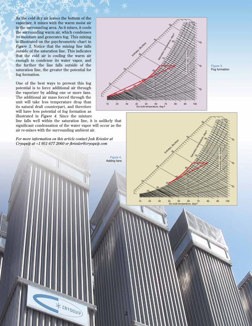
If the air sheds enough heat, it will reach the dew point. Any additional cooling will cause condensation of water vapor that is trapped in the air. This is illustrated in Figure 2 as cooling along the saturation line. Much of this condensed water vapor is deposited on the vaporizer as frost.
O
Figure 1. Initial Cooling
Figure 2.Condensation of water vapor
2
As the cold dry air leaves the bottom of the vaporizer, it mixes with the warm moist air in the surrounding area. As it mixes, it cools the surrounding warm air, which condenses its moisture and generates fog. This mixing is illustrated on the psychrometric chart in Figure 3. Notice that the mixing line falls outside of the saturation line. This indicates that the cold air is cooling the warm air enough to condense its water vapor, and the further the line falls outside of the saturation line, the greater the potential for fog formation.
One of the best ways to prevent this fog potential is to force additional air through the vaporizer by adding one or more fans. The additional air mass forced through the unit will take less temperature drop than its natural draft counterpart, and therefore will have less potential of fog formation as illustrated in Figure 4. Since the mixture line falls well within the saturation line, it is unlikely that significant condensation of the water vapor will occur as the air re-mixes with the surrounding ambient air.
For more information on this article contact Josh Kriesler at Cryoquip at +1 951 677 2060 or [email protected]
Figure 3. Fog formation
Figure 4. Adding fans
3
ith the installation of the world’s largest commercial hydrogen vehicle fueling station came a unique
set of specifications required to provide the high pressure flow of liquid hydrogen from its large storage tanks to its vaporizers. ACD’s SGV Series complies with all specifications and allows additional growth options for the customer.
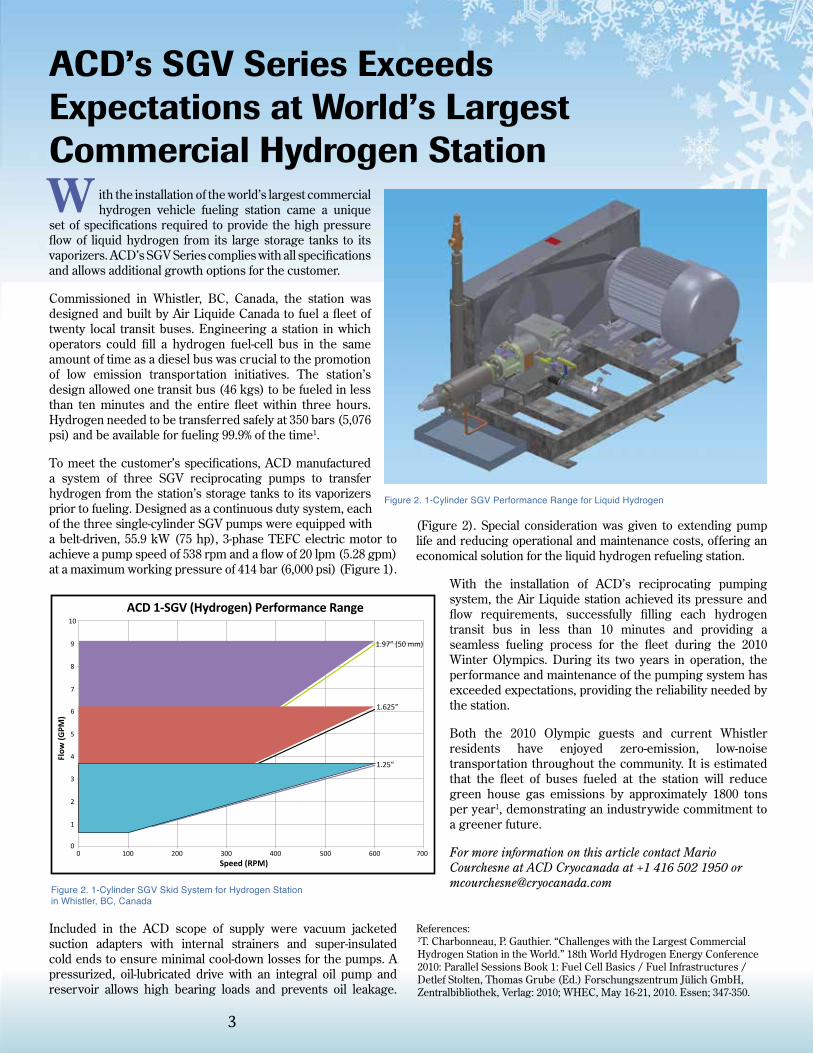
Commissioned in Whistler, BC, Canada, the station was designed and built by Air Liquide Canada to fuel a fleet of twenty local transit buses. Engineering a station in which operators could fill a hydrogen fuel-cell bus in the same amount of time as a diesel bus was crucial to the promotion of low emission transportation initiatives. The station’s design allowed one transit bus (46 kgs) to be fueled in less than ten minutes and the entire fleet within three hours. Hydrogen needed to be transferred safely at 350 bars (5,076 psi) and be available for fueling 99.9% of the time1.
To meet the customer’s specifications, ACD manufactured a system of three SGV reciprocating pumps to transfer hydrogen from the station’s storage tanks to its vaporizers prior to fueling. Designed as a continuous duty system, each of the three single-cylinder SGV pumps were equipped with a belt-driven, 55.9 kW (75 hp), 3-phase TEFC electric motor to achieve a pump speed of 538 rpm and a flow of 20 lpm (5.28 gpm) at a maximum working pressure of 414 bar (6,000 psi) (Figure 1).
Included in the ACD scope of supply were vacuum jacketed suction adapters with internal strainers and super-insulated cold ends to ensure minimal cool-down losses for the pumps. A pressurized, oil-lubricated drive with an integral oil pump and reservoir allows high bearing loads and prevents oil leakage.
(Figure 2). Special consideration was given to extending pump life and reducing operational and maintenance costs, offering an economical solution for the liquid hydrogen refueling station.
With the installation of ACD’s reciprocating pumping system, the Air Liquide station achieved its pressure and flow requirements, successfully filling each hydrogen transit bus in less than 10 minutes and providing a seamless fueling process for the fleet during the 2010 Winter Olympics. During its two years in operation, the performance and maintenance of the pumping system has exceeded expectations, providing the reliability needed by the station.
Both the 2010 Olympic guests and current Whistler residents have enjoyed zero-emission, low-noise transportation throughout the community. It is estimated that the fleet of buses fueled at the station will reduce green house gas emissions by approximately 1800 tons per year1, demonstrating an industrywide commitment to a greener future.
For more information on this article contact Mario Courchesne at ACD Cryocanada at +1 416 502 1950 or [email protected]
References: 1T. Charbonneau, P. Gauthier. “Challenges with the Largest Commercial Hydrogen Station in the World.” 18th World Hydrogen Energy Conference 2010: Parallel Sessions Book 1: Fuel Cell Basics / Fuel Infrastructures / Detlef Stolten, Thomas Grube (Ed.) Forschungszentrum Jülich GmbH, Zentralbibliothek, Verlag: 2010; WHEC, May 16-21, 2010. Essen; 347-350.
Figure 2. 1-Cylinder SGV Skid System for Hydrogen Station in Whistler, BC, Canada
ACD’s SGV Series Exceeds Expectations at World’s Largest Commercial Hydrogen Station
1.97” (50 mm)
1.625”
1.25”
70060050040030020010000
1
2
3
4
5
6
7
8
9
10
Flow
(GPM
)
Speed (RPM)
ACD 1-SGV (Hydrogen) Performance Range
Figure 2. 1-Cylinder SGV Performance Range for Liquid Hydrogen
W
itrogen gas requirements frequently experience significant changes in demand over time. Selecting the proper size of an on-site generator is important to achieve
an optimal cost structure. Generally the base load is assigned to a generator and the peak loads to imported liquid nitrogen. The cost of the on-site generated gas is a fraction of the imported liquid, so proper size selection is critical.
A Shortcut to Sizing Liquid-Add N2 Generators
N Most small liquid-add nitrogen generators do not turn down efficiently, so the power at partial load is nearly the same as full load. Therefore, oversized units waste power when the demand is less than the design flow. On the other hand, the imported liquid is substantially more expensive than the generated gas. Running the generator at partial load may still be cheaper than using liquid for a short period. The following is a “quick” method for proper size selection.
Step 1 • Determine a characteristic period
for load profiles. (This may be weekly, monthly, or other.)
• Select a measuring “interval” (minutes, hours, shifts, etc).
• Obtain data on average flows for each interval over the period.
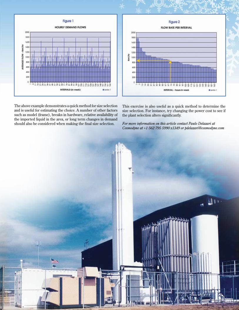
Example: See Figure 1 – Here the period is weekly, the interval is hourly, and the flow is in Nm3/hr.
Step 2 • Rearrange the intervals in
descending order of flow. Hint: using a spread sheet program makes this task easy.
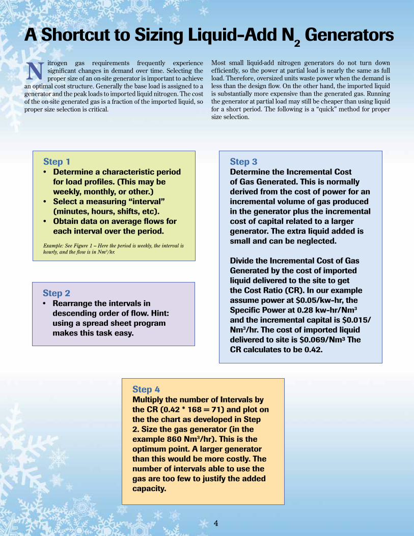
Step 3 Determine the Incremental Cost of Gas Generated. This is normally derived from the cost of power for an incremental volume of gas produced in the generator plus the incremental cost of capital related to a larger generator. The extra liquid added is small and can be neglected. Divide the Incremental Cost of Gas Generated by the cost of imported liquid delivered to the site to get the Cost Ratio (CR). In our example assume power at $0.05/kw-hr, the Specific Power at 0.28 kw-hr/Nm3 and the incremental capital is $0.015/Nm3/hr. The cost of imported liquiddelivered to site is $0.069/Nm³ The CR calculates to be 0.42.
Step 4 Multiply the number of Intervals by the CR (0.42 * 168 = 71) and plot on the the chart as developed in Step 2. Size the gas generator (in the example 860 Nm3/hr). This is the optimum point. A larger generator than this would be more costly. The number of intervals able to use the gas are too few to justify the added capacity.
4
5
A Shortcut to Sizing Liquid-Add N2 Generators
This exercise is also useful as a quick method to determine the size selection. For instance, try changing the power cost to see if the plant selection alters significantly.
For more information on this article contact Paulo Delazari at Cosmodyne at +1 562 795 5990 x1349 or [email protected]
The above example demonstrates a quick method for size selection and is useful for estimating the choice. A number of other factors such as model (frame), breaks in hardware, relative availability of the imported liquid in the area, or long term changes in demand should also be considered when making the final size selection.
6
but not continuously. Process engineers have two solutions to this problem, use two small vaporizers and switch between them when they become heavily covered in frost, either switching on the gas or liquid side of the vaporizers, (see figure 2) or use one large vaporizer designed to operate continuously. Providing each option is designed with sufficient surface area to provide enough energy for the vaporization, either solution is viable. The question is which is the best solution?
A switching system (see figure 3) enables vaporizers to run one-at-a-time, typically alternating at regular intervals. This allows the offline vaporizer to defrost while the online vaporizer operates at high efficiency. Piping “flutes” are built into the liquid inlet line to ensure that liquid is cut off from the vaporizers in the case where switching takes place on the exit gas side of the vaporizers. Switching times are variable so the system can operate efficiently regardless of location or ambient conditions and systems can be controlled by time or by temperature.
In simple terms it would seem that the decision to switch or not to switch becomes self evident, when the cost of the two vaporizers plus the switching system is greater than the single vaporizer. However, the vaporizer switching system is an electro mechanical device which requires power and maintenance and by definition affects reliability. A single vaporizer eliminates these issues. Two vaporizers may need more space than a single vaporizer, but the
operation is more flexible. The switching system also provides the opportunity for controlling the exit temperature of the gas which in some applications is critical. The latter control method also affords the opportunity to provide the installation with a low temperature shut down feature protecting down stream piping which might be susceptible to low temperatures and possible catastrophic failure. So to switch or not to switch is not quite so simple a question, and requires process engineers to carefully review a number of issues relating to the installation of ambient vaporizers.
For more information on this article contact Tim Born at Cryoquip Australia at +613 9791 7888 or [email protected]
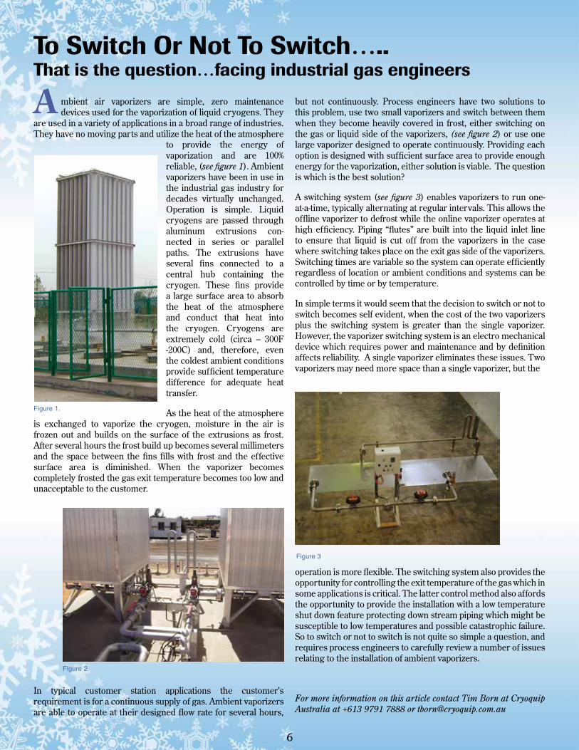
mbient air vaporizers are simple, zero maintenance devices used for the vaporization of liquid cryogens. They
are used in a variety of applications in a broad range of industries. They have no moving parts and utilize the heat of the atmosphere
to provide the energy of vaporization and are 100% reliable, (see figure 1). Ambient vaporizers have been in use in the industrial gas industry for decades virtually unchanged. Operation is simple. Liquid cryogens are passed through aluminum extrusions con-nected in series or parallel paths. The extrusions have several fins connected to a central hub containing the cryogen. These fins provide a large surface area to absorb the heat of the atmosphere and conduct that heat into the cryogen. Cryogens are extremely cold (circa – 300F -200C) and, therefore, even the coldest ambient conditions provide sufficient temperature difference for adequate heat transfer.
As the heat of the atmosphere is exchanged to vaporize the cryogen, moisture in the air is frozen out and builds on the surface of the extrusions as frost. After several hours the frost build up becomes several millimeters and the space between the fins fills with frost and the effective surface area is diminished. When the vaporizer becomes completely frosted the gas exit temperature becomes too low and unacceptable to the customer.
In typical customer station applications the customer’s requirement is for a continuous supply of gas. Ambient vaporizers are able to operate at their designed flow rate for several hours,
To Switch Or Not To Switch…..That is the question…facing industrial gas engineers
A
Figure 1.
Figure 3
Figure 2
nergent is developing energy recovery technology in cryogenic and other industrial processes having two-phase Joule-Thomson valves . The Variable Phase Turbine
technology, as it is known, is also being applied to recover waste heat and to produce geothermal power, two forms of Green Energy . In most of these processes involving liquid and gas, separation is required.
Conventional gravity separators, while reliable, can have several drawbacks. Foremost among these are size, weight and cost. For example, a typical offshore production separator string was reported to weigh ~670 tons and to require a footprint of ~270 square meters . Another commonly recurring problem is generation of foam, limiting the production flow rate, known as “bottle necking”. Air separation, LNG production and other refrigeration processes all require gas-liquid separators.
Energent has a unique technology known as the Separating Variable Phase Turbine (“SVPT”) that combines energy recovery with compact, high “G” separation. This technology when applied to the combination of a two-phase Joule-Thomson valve and gravity separator can reduce the weight and footprint by a factor of 10 or more while generating power in a single compact device. For example, the study quoted, ibid 3, found that application of this technology reduced the weight and footprint of the separation string by a factor of more than 10 while generating power from the flashing liquid flows equivalent to that of a large gas turbine.
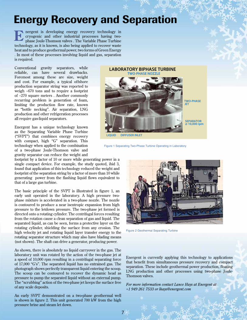
The basic principle of the SVPT is illustrated in figure 1, an early unit operated in the laboratory. A high pressure two-phase mixture is accelerated in a two-phase nozzle. The nozzle is contoured to produce a near isentropic expansion from high pressure to the letdown pressure. The two-phase jet formed is directed onto a rotating cylinder. The centrifugal forces resulting from the rotation cause a clean separation of gas and liquid. The separated liquid, as can be seen, forms a protective layer on the rotating cylinder, shielding the surface from any erosion. The high velocity jet and rotating liquid layer transfer energy to the rotating separator structure which may also have blading means (not shown). The shaft can drive a generator, producing power.
As shown, there is absolutely no liquid carryover in the gas. The laboratory unit was rotated by the action of the two-phase jet at a speed of 10,000 rpm resulting in a centrifugal separating force of 17,000 “G’s”. The separated liquid has no entrained gas. The photograph shows perfectly transparent liquid entering the scoop. The scoop can be contoured to recover the dynamic head as pressure to pump the separated liquid without an external pump. The “scrubbing” action of the two-phase jet keeps the surface free of any scale deposits.
An early SVPT demonstrated on a two-phase geothermal well is shown in figure 2. This unit generated 700 kW from the high pressure brine and steam let down.
Figure 2 Geothermal Separating Turbine
Energent is currently applying this technology to applications that benefit from simultaneous pressure recovery and compact separation. These include geothermal power production, floating LNG production and other processes using two-phase Joule-Thomson valves.
For more information contact Lance Hays at Energent at +1 949 261 7533 or [email protected]
7
Energy Recovery and Separation
E
LABORATORY BIPHASE TURBINETWO-PHASE NOZZLE
TWO-PHASE JET
SEPARATOR@ 10,000 rpm
LIQUID DIFFUSER INLET
Figure 1 Separating Two-Phase Turbine Operating in Laboratory
We are the proud sponsor of promotional booth #2As a valued customer/contact of ours we would urge you to consider joining us at this progressive event for our
industry. gasworld is expecting over 200 industrial gas professionals - many from the ASEAN region.
As well as a two day conference featuring presentations from top industry professionals, there is also an exhibition, and several evening events offering fantastic opportunities to meet with the wider industry.
To book your place on the gasworld conference please contact Marketing and Events Manager Katie Hill, who will
Come and see us at gasworld’s SOUTH EAST ASIA INDUSTRIAL GAS CONFERENCE 2012
Industrial Gases – Supporting the Drive for Energy Efficiency and Application Growth in South East Asia
For more information, contact Marketing Manager Katie Hill [email protected]: +44 1872 225031 | www.gasworld.com/conferences
be more than happy to answer any questions and help you with the booking procedure.
Cryogenic Industries 25720 Jefferson Avenue Murrieta CA 92562