pub. 988-0154-77b suzuki electronic fluid level sensor
TRANSCRIPT
1
Suzuki Electronic Fluid Level Sensor
Installation Instructions This instruction sheet tells how to install your Fluid Level sensor and connect it to a NMEA 2000® network using Suzuki Modular Instrument System (SMIS) network components. You must refer to your digital gauge, sonar or GPS unit's manual for sensor operation instructions.
All Suzuki SMIS network-capable devices are either NMEA 2000-certified or certification is pending. See our web site for the latest product status information.
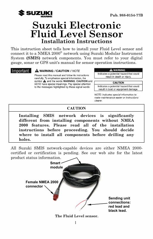
The Fluid Level sensor.
Female NMEA 2000 connector
Smartmodule
Sending unit connections:red lead and black lead.
CAUTION
Installing SMIS network devices is significantly different from installing components without NMEA 2000 features. Please read all of the installation instructions before proceeding. You should decide where to install all components before drilling any holes.
Pub. 988-0154-77B

2
This sensor consists of a smart module with a blue female locking cable connector on one end and two bare wires on the other. The cable length from the connector to the smart module is 18 inches (46 cm) and from the smart module to the bare wires is 10 feet (3 meters). The smart module converts fluid level information received from the sending unit (fluid level arm or potentiometer) to the NMEA 2000 data format. This allows any digital gauge, sonar or GPS unit connected to the SMIS network to display the fluid level. The sensor is most commonly used in fuel tanks, but it is designed to monitor fluid levels in almost any situation, including live wells, oil reservoirs, fresh water, gray water or black water tanks. The Fluid Level sensor is designed only for use with a SMIS Network. It must be connected to a NMEA 2000 network or it will not function. Tools and Supplies A T connector is the only electronic component needed to attach it to an existing SMIS network.
The photo above includes a 2 foot (61 cm) extension cable, T connector,
120-ohm male terminator and 120-ohm female terminator.
NOTE: All connectors used to add a fluid level sensor to a NMEA 2000 network will be black Devicenet connectors as shown above.
For complete instructions on setting up a new SMIS network or expanding an existing one refer to the NMEA 2000 Installation Instructions packed with your fluid level sensor. Sending unit mounting plate configurations vary. You will need whatever tools and electrical connectors that will work with your tank sending unit's specific design. Recommended tools include: pliers. If you need to route the smart module or cable connector through a bulkhead, you will need a drill and a 7/8" (22 mm) drill bit. Supplies are not included, unless otherwise indicated. The sensor’s two lead wires are pre-stripped.

3
We recommend using marine-grade crimp-on connectors that will fit your sending unit's electrical connections. Installation This instruction sheet assumes the mounting bracket is connected to the fluid level arm (or potentiometer) and is already installed in the tank. The sensors wires — red (positive) and black (negative) — will connect to the sending unit's mounting bracket, on top of the tank.
Tip: The sensor is designed to be the only device receiving signals from the sending unit. If the sensor is replacing a previous gauge, make sure you remove all the old gauge wires before you begin. If this is a replacement, note which connection is positive before disconnecting the old wires.
Your first step is to attach marine-grade crimp-on connectors to both the red lead (+) and the black (–) lead. Attach appropriate connectors to wire leads. Next, attach the positive red lead to the sending unit's positive connector, usually located in the center of the mounting plate. Connect the negative black lead to the sending unit's negative connector. To be sure which connection is which, refer to the mounting instructions that came with the sending unit.
Connect wire leads to fluid level sending unit. This is a typical sending unit mounting bracket. The center threaded post is + and the blade is –.
Negative connector
Positiveconnector
WARNING
Do NOT connect the sensor's blue locking collar connector to the network until you have finished connecting the red and black leads to the sending unit. This reduces the risk of a stray spark when working around fuel tanks.
4
Finally, connect the blue locking collar connector to the SMIS network. Route the sensor's cable connector to the T on the network backbone where you intend to attach it, and plug it in. The sensor is ready to use. Connecting to a SMIS Network A SMIS network bus is an installed and operational network cable (backbone) running the length of your boat, connected to a power supply and properly terminated. Like your home’s telephone wiring with phones in different rooms connected to the same communications line, a network bus is the communications line into which NMEA 2000 sensors, devices and display units are attached at various locations in a boat. Network Nodes A network bus is built of network nodes attached to a backbone. A network node is made by inserting a T-shaped connector into the backbone (using the side sockets) and attaching a display unit or sensor to the bottom socket of the T. The T connectors are similar to telephone jacks. The backbone is similar to a phone line running through the boat. As phones must be connected to each other to communicate, only sensors and display units plugged into the NMEA network can share information.
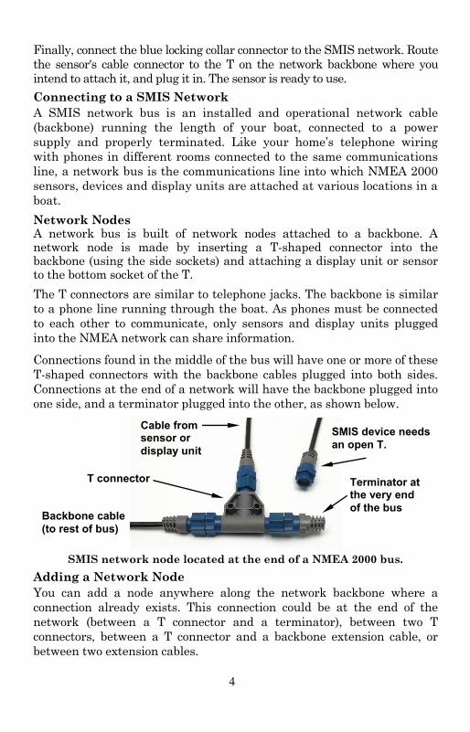
Connections found in the middle of the bus will have one or more of these T-shaped connectors with the backbone cables plugged into both sides. Connections at the end of a network will have the backbone plugged into one side, and a terminator plugged into the other, as shown below.
SMIS network node located at the end of a NMEA 2000 bus.
Adding a Network Node You can add a node anywhere along the network backbone where a connection already exists. This connection could be at the end of the network (between a T connector and a terminator), between two T connectors, between a T connector and a backbone extension cable, or between two extension cables.
Backbone cable (to rest of bus)
SMIS device needs an open T.
Terminator at the very end of the bus
Cable from sensor or display unit
T connector

5
Wherever you want to add the new node, simply separate the sockets of the old connection and attach your new T connector between them.
Add a new device to a SMIS network by attaching a T connector between
two T connectors, between a T connector and the end terminator, or between two backbone extension cables.
If you want to add a node at the end of the line (as shown in the previous figure), remove the terminator from the very last connector, securely attach the new T connector, and then attach the terminator on the new connector. Either method will allow you to add a device.
Additional Network Information Further instructions on creating or expanding a network are illustrated in the NMEA 2000 network setup booklet, which came packed with this instruction sheet.
Existing network node
Attachterminator at end of bus.
SMIS device connects to new T connector. Add T-shaped connector
to add device to bus.

6
Notes

7
LMF-200: Fluid Level Configuration & Calibration
To use a LMF-200 digital gauge to configure and calibrate a Suzuki Electronic Fluid Level, on a DeviceNet™ network, press MENU, select SYSTEM SETUP and press MENU. Highlight B. DEVICES and press MENU, which will open the Bus Devices list, a list of devices on the network. Bus Devices works as the device manager for the bus, allowing you to configure and unconfigure devices and set and reset critical values such as alarms and calibration. If you configure or reconfigure a sensor, you are assigning or reassigning its configuration name in the LMF-200 to a different tank location on the boat. NOTE:
You will notice the LMF-200 does not have an Exit key. Menus will time out after a preset amount of time (3, 5, 10 or 15 seconds). Refer to your LMF-200 instruction manual for more information on the Timeout feature.
LMF-200 Multi-function Digital Gauge
Boat Setup If this is the first time you have turned on your LMF-200, you will have to complete Boat Setup before you will be able to configure or calibrate your fluid level. If you have already completed Boat Setup, skip ahead to the segment covering fluid level configuration. NOTE:
If you want to access the Setup screen (Boat Setup) after an engine-tank configuration has been chosen you will have to reset the configuration to default settings. To reset configuration, press MENU, highlight SYSTEM SETUP and press MENU. Choose ENG/TANK and

8
press MENU twice. The following message will appear: Hit menu to reset Eng/Tnk. Press MENU. The Setup screen will appear with Boat Setup highlighted.
To execute Boat Setup: 1. With Boat Setup highlighted on the screen, press MENU. The Boat Setup menu will appear, allowing you to select an engine-tank configuration that matches the number of engines and fuel tanks on your vessel. Boat Setup options include: 1 En/1 Tk, 1 En/2 Tk, 2 En/1 Tk, 2 En/2 Tk, 3 En/1 Tk and 3 En/3 Tk. 2. Use the UP and DOWN keys to choose a configuration option that matches the number of engines and tanks on your vessel and press MENU. 3. If you selected a configuration with more than one tank you will have to select the tank you want to set up and press MENU, which will open the Tank Size window. (If you choose a single-tank configuration, you will not have to choose the tank. You will be directed straight to the Tank Size window, covered in Step 4.) 4. Use the UP and DOWN keys to input the number of gallons the tank will hold and press MENU. Repeat steps 3 and 4 for each additional tank. After all tanks have been set up, you will be directed to the main display. NOTE:
The Fuel Remaining Source must be set to fluid level for the unit to correctly display fuel level information from a fluid level sensor. It is set to Fuel Flow (Eng/FFlow) by default. Follow the instructions below to ensure fluid level (Fuel Level) has been selected as the Fuel Remaining Source.
Fuel Remaining Source (FRem Src) The Fuel Remaining source function allows you to select the device used to measure the amount the fuel remaining in the tank. To set Fuel Remaining Source to Fluid Level (Fuel Level): 1. Press MENU, use the UP and DOWN keys to select SYSTEM SETUP and press MENU. Select FUEL MNGR and press MENU.
2. Highlight FREM SRC and press MENU. That will open the FRem Src menu, which has two options: Eng/FFlow and Fuel level. 3. Use the UP and DOWN keys to select FUEL LEVEL and press MENU, which will take you back to the main display. You are now ready to configure and calibrate your Fluid Level sensor.

9
Fluid Level Configuration The LMF-200 can be configured with up to three tanks for each fluid level type, which includes Fuel, Fresh Water, Oil, Black Water, Waste Water (Gray Water) and Live Well. On the Bus Devices list, the fuel tanks will be displayed as F. Tnk (P) — Port, F. Tnk (C) — Center and F Tnk (S) — Starboard. If you have one tank it will be shown as F. Tnk. Tanks configured for Oil will follow the same format as fuel tanks; O. Tnk (single tank), O. Tnk (P), O. Tnk (C) or O. Tnk (S). When setting fluid level configuration for other fluid types you will be able to assign the tank a number in case you have more than one tank of a particular fluid type. The tanks will be listed with a tank number of your choosing; FrW Tnk1 (Fresh Water), BlkW Tnk2 (Black Water), LW Tnk3 (Live Well), etc. Fluid Level menu When you configure your Fluid Level sensor, it will be accessed from the Bus Devices list. The Fluid Level menu for unconfigured sensors will be different than the menu for configured sensors. A configured fluid level will have the following menu options: Unconfigure, Reconfigure, Level Warning, Calibrate, Reset Cal and Reset Values. The menu for an unconfigured fluid level will show the following configuration options: Fuel, Water, Waste Water (Gray Water), Black Water, Oil and Live Well. Caution:
If you configure your fluid level for fuel, you will NOT be able to get a fuel range reading. Fuel Range will NOT be calculated with a fluid level sensor. It will only be calculated with an engine interface, Fuel Flow or Storage Device.
To configure a fluid level for Fuel: 1. Press MENU, select SYSTEM SETUP and press MENU. Highlight B. DEVICES and press MENU. 2. Select an unconfigured fluid level (UnCfg FL) from the bus devices list and press MENU. The following message will appear: Hit Menu to Cfg FLev Sns. 3. Press MENU to open the fluid level menu. Select FUEL from the list of fluid types and press MENU. If your engine-tank configuration is set for multiple tanks, the Select Tank menu will appear with up to three options: Port Tank, Cen (Center) Tank and Stbd (Starboard) Tank.

10
NOTE: If your gauge is set to a single-tank configuration, you will not see the Select Tank menu. After selecting Fuel from the list of fluid types, you will be taken back to the Bus Devices list where the fluid level will be displayed as F. Tnk.
4. Highlight a tank option and press MENU. You will be taken back to the Bus Devices list, where your newly configured Fluid Level will be listed as: F. Tnk (P), F. Tnk (C) or F. Tnk (S), depending on the tank location you chose. NOTE:
If your fluid level is not updated on the Bus Devices list, refresh the list by letting it time out, and then access it again.
To configure a fluid level for Oil: 1. Press MENU, select SYSTEM SETUP and press MENU. Highlight B. DEVICES and press MENU. 2. Select the desired unconfigured fluid level (Unfcg FL) from the Bus Devices list and press MENU, which will launch the following message: Hit Menu to Cfg FLev Sns. 3. Press MENU, select OIL from the list of fluid types and press MENU. The Select Tank menu will appear with up to three options: Port Tank, Cen (Center) Tank and Stbd (Starboard) Tank. NOTE:
If your gauge is set to a single-tank configuration you will not see the Select Tank menu. You will be taken directly to the Tank Size menu (Step 5) after selecting Oil from the list of fluid types. Your fluid level will be displayed as O. Tnk.
4. Select a tank and press MENU, which will launch the Tank Size window. 5. Input the size of the tank (gallons) and press MENU. You will be directed to the Bus Devices list, where the fluid level you configured will be displayed as O. Tnk (P), O. Tnk (C) or O Tnk (S). NOTE:
If your fluid level is not updated on the Bus Devices list, refresh the list by letting it time out, and then access it again.
To configure a fluid level for Fresh Water, Waste Water (Gray Water), Live Well or Black Water: 1. Press MENU, select SYSTEM SETUP and press MENU. Highlight B. DEVICES and press MENU.

11
2. Select an unconfigured fluid level (Unfcg FL) from the Bus Devices list and press MENU, which will launch the following message: Hit Menu to Cfg FLev Sns. 3. Press MENU, select the desired configuration option (Fresh Water, Waste Water, Live Well or Black Water) from the list of fluid types and press MENU. The Tank Number window will appear. 4. Assign a tank number (1, 2 or 3) to your fluid level tank you are configuring and press MENU. That will launch the Tank Size window. 5. Input the capacity of the tank (gallons) and press MENU. You will be directed to the Bus Devices list, where the fluid level you configured will be displayed as FrW Tnk (1, 2 or 3), WtW Tnk (1, 2 or 3), LW Tnk (1, 2 or 3) or BlkW Tnk (1, 2 or 3). NOTE:
If your fluid level is not updated on the Bus Devices list, refresh the list by letting it time out, and then access it again.
To unconfigure a fluid level: 1. Press MENU, use the UP and DOWN keys to select SYSTEM SETUP and press MENU. Highlight B. DEVICES and press MENU. 2. Select a configured fluid level from the Bus Devices list and press MENU, which will open the fluid level menu with the following options: Configure, Unconfigure, Reconfigure, Level Warning, Calibrate, Reset Cal and Reset Values. 3. Highlight UNCONFIG (Unconfigure) and press MENU, which will launch the following message: Hit Menu to Unset Dev Name. 4. Press MENU and you will be taken back to the Bus Devices list where the fluid level you unconfigured will be listed as UnCfg FL. NOTE:
If your fluid level is not updated on the Bus Devices list, refresh the list by letting it time out, and then access it again.
To reconfigure a fluid level for Fuel: 1. Press MENU, use the UP and DOWN keys to select SYSTEM SETUP and press MENU. Highlight B. DEVICES and press MENU.
2. Select a configured fluid level from the Bus Devices list and press MENU, which will open the fluid level menu with the following options: Unconfigure, Reconfigure, Level Warning, Calibrate, Reset Cal and Reset Values. 3. Highlight RECONFIG (Reconfigure) from the Configuration Options menu and press MENU. That will open the Fluid Type menu.

12
4. Select FUEL from the list of fluid types and press MENU. If your unit is set to a multiple-tank configuration, the Select Tank menu will appear with up to three options: Port Tnk, Cen (Center) Tnk and Stbd (Starboard) Tnk.. (If your unit is set to a single-tank configuration, you will be taken back to the Bus Devices list.) NOTE:
If the desired configuration name (Port, Center or Starboard) is already configured to another EP sensor, you will have to unconfigure that sensor to make the desired configuration name available for the sensor you are trying to reconfigure.
5. Highlight a tank option and press MENU. You will be taken back to the Bus Devices list, where your newly configured Fluid Level will be listed as: F. Tnk (P), F. Tnk (C) or F. Tnk (S), depending on the tank location you chose.
NOTE: If your fluid level is not updated on the Bus Devices list, refresh the list by letting it time out, and then access it again.
To reconfigure a fluid level for Oil: 1. Press MENU, use the UP and DOWN keys to select SYSTEM SETUP and press MENU. Highlight B. DEVICES and press MENU.
2. Select a configured fluid level from the Bus Devices list and press MENU, which will open the fluid level menu with the following options: Unconfigure, Reconfigure, Level Warning, Calibrate, Reset Cal and Reset Values. 3. Highlight RECONFIG (Reconfigure) from the Configuration Options menu and press MENU. 4. Select OIL from the list of fluid types and press MENU. The Select Tank menu will appear with up to three options: Port Tnk, Cen (Center) Tnk and Stbd (Starboard) Tnk. NOTE:
If the desired configuration name (Port, Center or Starboard) is already configured to another EP sensor, you will have to unconfigure that sensor to make the desired configuration name available for the sensor you are trying to reconfigure.
5. Select a tank and press MENU, which will launch the Tank Size window. 6. Input the size of the tank (gallons) and press MENU. You will be directed to the Bus Devices list, where the fluid level you configured will be displayed as O. Tnk (P), O. Tnk (C) or O Tnk (S).

13
NOTE: If your fluid level is not updated on the Bus Devices list, refresh the list by letting it time out, and then access it again.
To reconfigure a fluid level for Fresh Water, Waste Water (Gray Water), Live Well or Black Water: 1. Press MENU, use the UP and DOWN keys to select SYSTEM SETUP and press MENU. Highlight B. DEVICES and press MENU.
2. Select a configured fluid level from the Bus Devices list and press MENU, which will open the fluid level menu with the following options: Unconfigure, Reconfigure, Level Warning, Calibrate, Reset Cal and Reset Values. 3. Highlight RECONFIG (Reconfigure) from the Configuration Options menu and press MENU. That will open the Fluid Type menu. Highlight Fresh Water, Waste Water (Gray Water), Live Well or Black Water and press MENU. The Tank Number window will appear. 4. Assign a tank number (1, 2 or 3) to the tank using the fluid level you are configuring and press MENU. That will launch the Tank Size window. You can have up to three tanks for each fluid type. 5. Input the capacity of the tank (gallons) and press MENU. You will be directed to the Bus Devices list, where the fluid level you configured will be displayed with its new configuration. NOTE:
If your fluid level is not updated on the Bus Devices list, refresh the list by letting it time out, and then access it again.
Reset The Reset command will reset all values for a device, including configuration and calibration settings. To use Reset command: 1. Press MENU, select SYSTEM SETUP and press MENU. Highlight B. DEVICES and press MENU. 2. Select a configured fluid level and press MENU, which will open the Configuration Options menu. 3. Highlight RESET and press MENU. The following message will appear: Hit Menu to Rst Values. WARNING:
If you reset any individual EP sensor, it will lose all configuration and calibration settings.

14
4. Press MENU to reset the selected fluid level’s configuration and calibration information to the default settings. You will be taken back to the Bus Devices list where the selected fluid level will be displayed as UnCfg FL. NOTE:
If your fluid level is not updated on the Bus Devices list, refresh the list by letting it time out, and then access it again.
Fluid Level Calibration The factory calibration settings for a Fluid Level should be adequate for the majority of applications, so calibration will not be necessary in most cases. If, however, the tank has an irregular shape or greater accuracy is needed, calibration is recommended. Your gauge has three calibration options: 2 point, 3 point and 5 point. 2-Point Calibration A 2-point calibration is best suited for rectangular or square-shaped tanks, where the capacity of the top half of the tank matches the capacity in the lower half of the tank. In a two-point calibration, you will set two points, one each for empty and full levels. You can begin calibration at either of the two points, but we recommend starting with an empty tank. You will fill the tank to complete calibration. NOTE:
Adequate calibration may be achieved without calibrating both points and you can calibrate the points (Empty Level and Full Level) in any order you wish.
To execute 2-Point calibration: 1. Press MENU, select SYSTEM SETUP and press MENU. 2. Highlight B. DEVICES and press MENU, which will open the Bus Devices list. 3. Highlight the fluid level sensor you want to calibrate and press MENU. Select CAL (Calibrate) and press MENU. The Points menu will appear with three options: 2, 3 and 5. 4. Select 2 and press MENU. The Points menu will appear with two options: Empty Lev and Full Lev.
5. Make sure the tank is empty, then select EMPTY LEV from the Points menu and press MENU. The following message Tnk to Empty lev hit Menu. Press MENU. Fill up the tank.
15
6. When the tank has been filled, follow steps 1-4 to access the Points menu. Highlight FULL LEV and press MENU. The following message will appear: Tnk to Full lev hit Menu. Press MENU and let the menus time out, which will take you to the main display. 3-Point Calibration: 3-point calibration is designed for tanks that vary in shape from the top to the bottom. You can begin calibration at any point in the 3-point process, but we recommend starting calibration with an empty tank. In a 3-point calibration, you will set three points, one each for empty, half and full levels.
NOTE: Adequate calibration my be achieved without calibrating all three points and you can calibrate the points (Empty Level, Half Level and Full Level) in any order you wish.
To execute 3-Point calibration: 1. Press MENU, select SYSTEM SETUP and press MENU. 2. Highlight B. DEVICES and press MENU, which will open the Bus Devices list. 3. Highlight the fluid level sensor you want to calibrate and press MENU, then select CAL (Calibrate) and press MENU. The Points menu will appear with three options: 2, 3 and 5. 4. Select 3 and press MENU. The Points menu will appear with three options: Empty Lev, Half Lev and Full Lev. 5. Make sure your tank is empty, then highlight EMPTY LEV and press MENU. The following message will appear: Tnk to Empty lev hit Menu. Press MENU. 6. Add a half a tank of fuel. If, for example, you have a 100 gallon tank, add 50 gallons of fuel. Repeat steps 1-4, then select HALF LEV from the Points menu and press MENU. The following message will appear: Tnk to Half lev hit Menu. Press MENU. 7. Fill up the tank and repeat steps 1-4 to access Points menu. Highlight FULL LEV and press MENU. The following message will appear: Tnk to Full lev hit Menu. 8. Press MENU and let the menus time out, which will take you to the main display. 5-point Calibration 5-point calibration is best suited tanks that vary greatly in shape from top to bottom. You can begin calibration at any point in the 5-point calibration process.

16
We recommend starting calibration with an empty tank. In a five-point calibration you will set five points: Empty Level, 1 Qtr Level, Half Level, 3 Qtr Level and Full Level. NOTE:
Adequate calibration may be achieved without calibrating all five points and you can calibrate the points (Empty Level, 1 Quarter Level, Half Level, 3 Quarter Level and Full Level) in any order you wish.
To execute 5-Point calibration: 1. Press MENU, select SYSTEM SETUP and press MENU. 2. Highlight B. DEVICES and press MENU, to open the Bus Devices list. 3. Highlight the fluid level sensor you want to calibrate and press MENU, then select CAL (Calibrate) and press MENU. The Points menu will appear with three options: 2, 3 and 5. 4. Select 5 and press MENU. The Points menu will appear with five options: Empty lev, 1 Qtr lev, Half lev, 3 Qtr lev and Full Lev. 5. Make sure your tank is empty, then highlight EMPTY LEV and press MENU. The following message will appear: Tnk to Empty lev hit Menu. Press MENU. 6. Fill up one quarter of the tank. If you had a 100 gallon tank, you would add 25 gallons of fuel. Repeat steps 1-4, then select 1 QTR LEV from the Points menu and press MENU. The following message will appear: Tnk to 1 Qtr lev hit Menu. Press MENU. 7. Fill up the tank halfway. If you had a 100 gallon tank, you would add another 25 gallons of fuel. Repeat steps 1-4 to access the Points menu, then highlight HALF LEV and press MENU. The following message will appear: Tnk to Half lev hit Menu. Press MENU. 8. Fill up three quarters of the tank. If you had a 100 gallon tank, you would add another 25 gallons of fuel. Repeat steps 1-4 to access the Points menu, then highlight 3 QTR LEV and press MENU. The following message will appear: Tnk to 3 Qtr lev hit Menu. Press MENU. 9. Top off the tank and repeat steps 1-4 to access the Points menu, then highlight FULL LEV and press MENU. The following message will appear: Tnk to Full lev hit Menu. Press MENU and let the menus time out, which will take you back to the main display. Reset Calibration The Reset Calibration command allows you to reset a fluid level's calibration back to factory default settings.
17
You should only reset calibration when you believe calibration settings for your Fluid Level are incorrect. To Reset Calibration: 1. Press MENU, use the UP and DOWN keys to select SYSTEM SETUP and press MENU. 2. Highlight B. DEVICES and press MENU. Select the desired fluid level and press MENU. 3. Select RST CAL from the fluid level menu and press MENU. The following message will appear: Hit Menu to Rst the Cal. 4. Press MENU to set calibration back to factory default settings. To recalibrate the fluid level, revisit the segment covering fluid level calibration. NOTE:
If you have calibrated your fluid level sensor and are having problems with the sensor's performance, be sure to check the sending unit. You can do this by using an ohm meter to test the resistance of the unit. Connect the sending unit hot wire (usually pink) and the ship or sending unit ground wire (usually black) to the ohm meter. With the tank full, the resistance should be around 33-1/2 ohms. When the tank is the empty, the resistance should be around 240 ohms. If, when the tank is full or empty, the ohm readings are significantly different from the standard full (33-1/2) and empty (240) ohms levels, there is a problem with the sending unit. If the ohm readings are the same in both cases, the sending unit is stuck.

18
Notes

19
LMF-400: Fluid Level Configuration & Calibration
To use the LMF-400 digital gauge to configure or calibrate a Suzuki Electronic Fluid Level on a DeviceNet™ network, press MENU, select SYSTEM SETUP and press ENTER. Highlight BUS DEVICES and press ENTER to open the Bus Devices list. Bus Devices works as the device manager for the bus, allowing you to configure and unconfigure devices and set and reset critical values such as alarms and calibration.
LMF-400 Multi-function Digital gauge.
Boat Setup If this is the first time you have turned on your LMF-400, you will have to complete Boat Setup before you will be able to configure or calibrate your fluid level. If you have already completed Boat Setup, skip ahead to the segment covering Fluid Level Configuration.
NOTE: If you want to access the Setup Menu (Boat Setup) after an engine-tank configuration has been chosen, press MENU, highlight SYSTEM SETUP and press ENTER. Choose ENG/TANK CFG and press ENTER twice. The following message will appear: Press ENTER to reset Eng/Tnk Cfg. Press MENU. The Setup Menu will appear with Boat Setup highlighted.
To execute Boat Setup: 1. With Boat Setup highlighted on the screen, press ENTER. A menu will appear, allowing you to choose the number of engines and fuel tanks on your vessel. The Boat Setup menu options are: 1 Eng/1 Tank, 1 Eng/2 Tank, 2 Eng/1 Tank, 2 Eng/2 Tanks, 3 Eng/1 Tank or 3 Eng/3 Tanks.

20
2. Use the UP and DOWN keys to select the engine-tank configuration that applies to your vessel and press ENTER. After setting the engine/tank configuration, the Tank Size menu will appear with up to three options (Port Tank, Center Tank and Starboard Tank), depending on the engine tank configuration you chose. (If you selected one tank during Boat Setup, you will be taken directly to the Setting Tank Size Window in Step 4.) 3. Select the desired tank and press ENTER, which will open the Setting Tank Size window. 4. Use the UP and DOWN keys to input the number of gallons the tank will hold and press ENTER. Press EXIT and repeat steps 3 and 4 for each of the remaining tanks. 5. After all tanks on your vessel have been set up, press EXIT repeatedly to return to the main display. NOTE:
The Fuel Remaining Source must be set to fluid level for the unit to correctly display fuel level information from a fluid level sensor. It is set to Fuel Flow (Eng/FFlow) by default. Follow the instructions below to ensure fluid level (Fuel Level) has been selected as the Fuel Remaining Source.
Fuel Remaining Source The Fuel Remaining source function allows you to select the device used to measure the amount the fuel remaining in the tank. To change Fuel Remaining Source to fluid level (Fuel Level):
1. Press MENU, use the UP and DOWN keys to select SYSTEM SETUP and press ENTER. 2. Highlight FUEL SETUP and press ENTER. 3. Select FUEL REM SRC (Fuel Remaining Source) and press ENTER. 4. Highlight the FUEL LEV SNSR (Fluid Level Sensor) and press ENTER. You are ready to configure your fluid level sensor.
Fluid Level Configuration The LMF-400 will support up to three tanks for each Fluid Level type which includes: Fuel, Fresh Water, Oil, Black Water, Waste Water (Gray Water) and Live Well.
On the Bus Devices list, the fuel tanks will be displayed as Fuel Tank (P) — Port Fuel Tank (C) — Center, and Fuel Tank (S) —Starboard. If you chose a single-tank configuration in Boat Setup, the tank will be

21
listed as Fuel Tank. Like a fuel tank, the Oil Tank will also be listed by its engine location — Oil Tank (P), Oil Tank (C) or Oil Tank (S).
When setting fluid level configuration for other fluid types you will be able to assign the tank a number in case you have more than one tank of a particular fluid type. The tanks will be listed with a tank number of your choosing. By default, the tank number is set to 1.
Other fluid types will be displayed as BlkWtr Tnk (1, 2 or 3), FrshWtr Tnk (1, 2 or 3), LWell Tnk (1, 2 or 3) and WsteWtr Tnk (1, 2 or 3).
If the fluid level has not been configured, it will be listed as Unfcg F Lev on the bus devices list.
Bus Devices highlighted in the System Setup menu (left). Searching
Bus Devices window (center) with Bus Devices list (right). Fluid Level menu When you configure your Fluid Level sensor, it will be accessed from the Bus Devices list. The Fluid Level menu for unconfigured sensors will be different than the menu for configured sensors. A configured fluid level will have the following menu options: Unconfigure, Reconfigure, Level Warning, Calibrate, Reset Calibration and Reset Values. The menu of an unconfigured fluid level will show configuration options: Fuel, Fresh Water, Waste Water (Gray Water), Live Well, Oil and Black Water. Caution:
If you configure your fluid level for fuel, you will NOT be able to get a fuel range reading. Fuel Range will NOT be calculated with a fluid level sensor. It will only be calculated with an engine interface, EP-10 Fuel Flow or EP-50 Storage Device.
To configure a fluid level for Fuel: 1. Press MENU, use the UP and DOWN keys to select SYSTEM SETUP and press ENTER.
22
2. Highlight BUS DEVICES and press ENTER to open the Bus Devices list.
3. Select UNFCG F LEV and press ENTER. The following message will appear: Press Enter to configure Fluid Lev Snsr.
4. Press ENTER and the Fluid Level menu will appear with the following options: Fuel, Fresh Water, Waste Water (Gray Water), Live Well, Oil and Black Water.
5. Select FUEL and press ENTER, which will open the Select Tank menu with up to three options: Port Tank, Center Tank and Starboard Tank. The number of tank options depends on the engine-tank configuration you chose during Boat Setup.
NOTE: If your gauge is set to a single-tank configuration you will not see the Select Tank menu. You will be taken directly to the Bus Devices list where the tank will be displayed as Fuel Tank.
6. Select a tank option and press ENTER. You will be taken back to the Bus Devices list, where the tank will be displayed as Fuel Tank (P), Fuel Tank (C) or Fuel Tank (S). Press EXIT repeatedly to return to the main display. NOTE:
If your fluid level is not updated on the Bus Devices list, refresh the list by closing it, and then access it again.
To configure a fluid level for Oil: 1. Press MENU, use the UP and DOWN keys to select SYSTEM SETUP and press ENTER. 2. Highlight BUS DEVICES and press ENTER to bring up the Bus Devices list. 3. Select UNFCG F LEV and press ENTER. The following message will appear: Press Enter to configure Fluid Lev Snsr. 4. Press ENTER and the Fluid Level menu will appear with the following options: Fuel, Fresh Water, Waste Water (Gray Water), Live Well, Oil and Black Water. 5. Select Oil and press ENTER, which will open the Select Tank menu with up to three options: Port Tank, Center Tank and Starboard Tank.
NOTE: If your gauge is set to a single-tank configuration you will not see the Select Tank menu. You will be taken directly to Tank Size window.

23
6. Select a tank option and press ENTER. The Setting Tank Size window will appear. Input the size of the tank and press ENTER. You will be taken back to the Bus Devices list, where the tank will be displayed as Oil Tank (P), Oil Tank (C) or Oil Tank (S). Press EXIT repeatedly to return to the main display.
NOTE: If your fluid level is not updated on the Bus Devices list, refresh the list by closing it, and then access it again.
To configure a fluid level for Fresh Water, Waste Water (Gray Water), Live Well or Black Water:
1. Press MENU, use the UP and DOWN keys to select SYSTEM SETUP and press ENTER.
2. Highlight BUS DEVICES and press ENTER. The Bus Devices list will appear.
3. Select UNFCG F LEV and press ENTER. The following message will appear: Press Enter to configure Fluid Lev Snsr. Press ENTER and the Fluid Level configuration menu will appear.
4. Choose Fresh Water, Waste Water (Gray Water), Live Well or Black Water and press ENTER. The Tank Number window will appear.
5. Use the UP and DOWN keys to input the number you want to assign the tank and press ENTER. The Setting Tank Size window will appear.
6. Use the UP and DOWN keys to input the size of the tank and press ENTER. You will be taken back to the Bus Devices list, where the tank will be displayed as FrshWtr Tnk (1, 2 or 3), WsteWtr Tnk (1, 2 or 3). LWell Tnk (1, 2 or 3) or BlkWtr Tnk (1, 2 or 3).
NOTE: If your fluid level is not updated on the Bus Devices list, refresh the list by closing it, and then access it again.
To unconfigure a fluid level: 1. Press MENU, use the UP and DOWN keys to select SYSTEM SETUP and press ENTER. 2. Highlight BUS DEVICES and press ENTER, which will open the Bus Devices list. 3. Choose a configured Fluid Level from the Bus Devices list and press ENTER. The Fluid Level menu will appear with the following options: Level Warning, Unconfigure, Reconfigure, Calibrate, Reset Cal and Reset Values.

24
3. Highlight UNCONFIGURE and press ENTER, which will launch the following message: Press Enter to Unconfig Device name. 4. Press ENTER and you will be taken back to the Bus Devices list where the fluid level you unconfigured will be displayed as UnCfg F Level. NOTE:
If your fluid level is not updated on the Bus Devices list, refresh the list by closing it, and then access it again.
To reconfigure a fluid level for Fuel: 1. Press MENU, use the UP and DOWN keys to select SYSTEM SETUP and press ENTER. 2. Highlight BUS DEVICES and press ENTER to bring up the Bus Devices list. 3. Select the fluid level you want to reconfigure and press ENTER. The Fluid Level menu will appear with the following options: Fuel, Fresh Water, Waste Water (Gray Water), Live Well, Oil and Black Water. NOTE:
If the desired configuration name (Port, Center or Starboard) is configured to another EP sensor, you will have to unconfigure that sensor before you will be able to use the desired configuration name to reconfigure your fluid level.
4. Select FUEL and press ENTER, which will open the Select Tank menu with up to three options: Port Tank, Center Tank and Starboard Tank. The number of tank options depends on the engine-tank configuration you chose during Boat Setup. NOTE:
If the desired configuration name (Port, Center or Starboard) is already configured to another EP sensor, you will have to unconfigure that sensor to make the desired configuration name available for the fluid level you are trying to reconfigure.
6. Select a tank option and press ENTER. You will be taken back to the Bus Devices list, where the tank will be displayed as Fuel Tank (P), Fuel Tank (C) or Fuel Tank (S). Press EXIT repeatedly to return to the main display. To reconfigure a fluid level for Oil: 1. Press MENU, use the UP and DOWN keys to select SYSTEM SETUP and press ENTER. 2. Highlight BUS DEVICES and press ENTER to bring up the Bus Devices list.

25
3. Select the fluid level you want to reconfigure and press ENTER. The Fluid Level menu will appear with the following options: Fuel, Fresh Water, Waste Water (Gray Water), Live Well, Oil and Black Water. 4. Select OIL and press ENTER, which will open the Select Tank menu with up to three options: Port Tank, Center Tank and Starboard Tank. The number of tank options depends on the engine-tank configuration you chose during Boat Setup. NOTE:
If the desired configuration name (Port, Center or Starboard) is already configured to another EP sensor, you will have to unconfigure that sensor to make the desired configuration name available for the fluid level you are trying to reconfigure.
6. Select a tank option and press ENTER. The Setting Tank Size window will appear. Input the size of the tank and press ENTER. You will be taken back to the Bus Devices list, where the tank will be displayed as Oil Tank (P), Oil Tank (C) or Oil Tank (S). To reconfigure a fluid level for Fresh Water, Waste Water (Gray Water), Live Well or Black Water: 1. Press MENU, use the UP and DOWN keys to select SYSTEM SETUP and press ENTER. 2. Highlight BUS DEVICES and press ENTER. The Bus Devices list will appear. 3. Select the Fluid Level you want to reconfigure and press ENTER. 4. The Fluid Level menu will appear with the following options: Level Warning, Unconfigure, Reconfigure, Calibrate, Reset Cal and Reset Values. 5. Choose RECONFIGURE and press ENTER. The Fluid Level menu will appear with the following options: Fuel, Fresh Water, Waste Water (Gray Water), Live Well, Oil and Black Water. 6. Select Fresh Water, Waste Water (Gray Water), Live Well or Black Water and press ENTER. The Tank Number window will appear. 7. Use the UP and DOWN keys to input the tank number you want to assign the fluid level and press ENTER. The Setting Tank Size window will appear. 8. Use the UP and DOWN keys to input the size of the tank and press ENTER. You will be taken back to the Bus Devices list, where the fluid level will be displayed with its new configuration.

26
NOTE: If your fluid level is not updated on the Bus Devices list, refresh the list by closing it, and then access it again.
Reset Values Accessing the Reset Values command from the Fluid Level menu, allows you to reset the values of an individual fluid level without affecting the settings of any other sensor. To Reset Values: 1. Press MENU, use the UP and DOWN keys to select SYSTEM SETUP and press ENTER. 2. Highlight BUS DEVICES and press ENTER. The Bus Devices list will appear. 3. Select the fluid level you want to reset and press ENTER. The Fluid Level menu will appear with the following options: Level Warning, Unconfigure, Reconfigure, Calibrate, Reset Cal and Reset Values. 4. Choose RESET VALUES and press ENTER. The following message will appear: Press Enter to Reset Device Values. 5. Press ENTER to reset the fluid level's settings back to factory defaults. NOTE:
If you reset values from a fluid level menu, you will only restore default settings for that particular fluid level sensor. Executing the Reset Values command will clear the sensor's configuration and calibration settings.
Fluid Level Calibration The factory calibration settings for a Fluid Level should be adequate for the majority of applications, so calibration will not be necessary in most cases. If, however, the tank has an irregular shape or greater accuracy is needed, calibration is recommended. Your gauge has three calibration options: 2 point, 3 point and 5 point. 2-Point Calibration A 2-point calibration is best suited for rectangular or square-shaped tanks, where the capacity of the top half of the tank matches the capacity in the lower half of the tank. In a two-point calibration, you will set two points, one each for empty and full levels. You can begin calibration at either of the two points, but we recommend starting with an empty tank. You will fill the tank to complete calibration.

27
NOTE: Adequate calibration may be achieved without calibrating both points and you can calibrate the points (Empty Level and Full Level) in any order you wish.
To execute 2-Point calibration: 1. Before following the steps below, make sure your fuel tank is empty. 2. Press MENU, use the UP and DOWN keys to select SYSTEM SETUP and press ENTER. 3. Highlight BUS DEVICES and press ENTER. Choose the fluid level you want to calibrate and press ENTER. 4. Select CALIBRATE and press ENTER. The Number of Points menu will appear with three options: 2, 3 and 5. Select 2, for two-point calibration, and press ENTER. 5. The Levels menu will appear with two choices: Empty Level and Full Level. Choose EMPTY LEVEL and press ENTER. 6. The following message will appear: Set Tank to Empty Level Press Enter. Press ENTER. You will be taken back to the Levels menu. 7. Fill up your tank.
8. Select FULL LEVEL and press ENTER. The following message will appear: Set Tank to Full Level Press Enter.
9. Press ENTER. Press EXIT repeatedly to return to the main display. 3-Point Calibration 3-point calibration is designed for tanks that vary in shape from the top to the bottom. You can begin calibration at any point in the 3-point process, but we recommend starting calibration with an empty tank. In a 3-point calibration, you will set three points, one each for empty, half and full levels. NOTE:
Adequate calibration may be achieved without calibrating all three points and you can calibrate the points (Empty Level, Half Level and Full Level) in any order you wish.
To execute 3-Point calibration: 1. Before following the steps below, make sure your fuel tank is empty. 2. Press MENU, use the UP and DOWN keys to select SYSTEM SETUP and press ENTER. 3. Highlight BUS DEVICES and press ENTER. Choose the fluid level you want to calibrate and press ENTER.
28
4. Select CALIBRATE and press ENTER. The Number of Points menu will appear with three options: 2, 3 and 5. Select 3, for three-point calibration, and press ENTER. 5. Highlight EMPTY LEVEL and press ENTER. The following message will appear: Set Tank to Empty Level Press Enter. 6. Press ENTER. You will be taken back to the Levels menu. 7. Add half a tank of fuel. (If you had a 100 gallon tank, you would add 50 gallons.) 8. Select HALF LEVEL and press ENTER. The following message will appear: Set Tank to Half Level Press Enter. 9. Press ENTER. You will be taken back to the Levels menu. 10. Fill up your tank. 11. Highlight FULL LEVEL and press ENTER. The following message will appear: Set Tank to Full Level Press Enter. 12. Press ENTER. You will be taken back to the Levels menu. Press EXIT repeatedly to return to the main display. 5-Point Calibration 5-point calibration is best suited for tanks that vary greatly in shape from top to bottom. You can begin calibration at any point in the 5-point calibration process. We recommend starting calibration with an empty tank. In a five-point calibration there are five calibration points: Empty Level, 1 Qtr Level, Half Level, 3 Qtr Level and Full Level. NOTE:
Adequate calibration may be achieved without calibrating all five points and you can calibrate the points (Empty Level, 1 Quarter Level, Half Level, 3 Quarter Level and Full Level) in any order you wish.
To execute 5-Point calibration: 1. Before following the steps below, make sure your fuel tank is empty. Press MENU, use the UP and DOWN keys to select SYSTEM SETUP and press ENTER. 2. Highlight BUS DEVICES and press ENTER. Choose the fluid level you want to calibrate and press ENTER. Select CALIBRATE and press ENTER. The Number of Points menu will appear with three options: 2, 3 and 5. Select 5, for three-point calibration and press ENTER. 3. The Levels menu will appear with five options: Empty Level, 1 Qtr Level, Half Level, 3 Qtr Level and Full level. Select EMPTY LEVEL and press ENTER. The following message will appear: Set Tank to Empty Level Press Enter.

29
4. Press ENTER. You will be taken back to the Levels menu. Add 1-quarter tank of fuel. (If, for example, you have a 100-gallon tank, add 25 gallons of fuel.) 5. Highlight 1 QTR LEVEL and press ENTER. The following message will appear: Set Tank to 1 Qtr Level Press Enter. 6. Press ENTER. You will be taken back to the Levels menu. Fill your tank up halfway. (If, for example, you have a 100-gallon tank, add another 25 gallons of fuel.) 7. Highlight HALF LEVEL and press ENTER. The following message will appear: Set Tank to Half Level Press Enter. Press ENTER. You will be taken back to the Levels menu. 8. Fill your tank to the 3 quarter level. (If you have a 100-gallon tank, add 25 gallons of fuel.) Highlight 3 QTR LEVEL and press ENTER. The following message will appear: Set Tank to 3 Qtr Level Press Enter. 9. Press ENTER. You will be taken back to the Levels menu. Fill up your tank, then select FULL LEVEL and press ENTER. The following message will appear: Set Tank to Full Level Press Enter. 10. Press ENTER. You will be taken back to the Levels menu. Press EXIT repeatedly to get back to the main display. Reset Calibration The Reset Calibration command allows you to reset a fluid level back to factory default settings. You will only need to reset calibration when you believe your fluid level has been calibrated incorrectly. To Reset Calibration: 1. Press MENU, select SYSTEM SETUP and press ENTER. 2. Highlight BUS DEVICES and press ENTER. Select the fluid level you want to reset and press ENTER. 3. Highlight RESET CAL from the fluid level menu and press ENTER. The following message will appear: Press Enter to reset Calibration. 4. Press ENTER to set calibration back to factory default settings. You will be taken back to the Bus Devices list. NOTE:
If you have calibrated your fluid level sensor and are having problems with its performance, be sure to check the sending unit. You can do this by using an ohm meter to test the resistance of the unit. Connect the sending unit hot wire (usually pink) and the ship or sending unit ground wire (usually black) to the ohm meter. With the tank full, the resistance should be around 33-1/2 ohms. When the tank is the empty, the resistance should be around 240 ohms.

30
If, when the tank is full or empty, the ohm readings are significantly different from the standard full (33-1/2) and empty (240) ohms levels, there is a problem with the sending unit. If the ohm readings are the same in both cases, the sending unit is stuck.

31
How to Obtain Service… …in the USA: Contact your nearest Suzuki Marine Dealer …in Canada: Contact your nearest Suzuki Marine Dealer …outside Canada and the USA: Contact the dealer in the country where you purchased your unit.
Accessory Ordering Information Please contact your local Suzuki Marine dealer. To locate a Suzuki Marine dealer, visit the web site, www.suzukimarine.com, and look for the Dealer Locator. To locate a Canadian Suzuki Marine dealer, visit the web site, http://www.suzuki.ca, and look for the Dealer Locator. Or, consult your telephone directory for listings.

32
© Copyright 2009 All Rights Reserved American Suzuki Motor Corp. 988-0154-77B