quick start tutorial introduction - guilleviniag.com nano/nano... · quick start tutorial...
TRANSCRIPT
1
Quick Start Tutorial
Introduction
This document provides all the basic knowledge to help you develop your first TSX NanoPLC application using PL7-07 programming software.It is divided into four parts :
1 Required hardware configuration for PL7-072 Installing PL7-07 programming software3 Main menu bar4 Programming tutorial (using example)
1 Required hardware configuration
1.1 Compatibility
The following class and/or types of computers can run the PL7-07 programming software:
• IBM PC-AT compatible machines
• Programming terminals
- FTX 417 20/ 417 40 (1)
- FTX 507.55 or FTX 507 6B/8C/8T/9T(1)
(1) recommended terminals for optimal performance
1.2 Configuration
The computer system should meet these minimum requirements:
• minimum 286 CPU, recommended 386 CPU or higher (running at least 20 Mhz)
• 640 kB of RAM and 2 megabytes of available extended memory
• 3 megabytes of available hard disk space
• EGA, VGA, or SVGA monitor
• One available COM serial port—COM1 through COM4
• One parallel port for printing—LPT1 through LPT4
• MS-DOS version 3.3 or higher
Typical configuration• 286 microprocessor or higher
Although the PL7-07 PC programming software will run on a computer with the minimumrequirements above, you may experience slow performance if you have multiplewindows open simultaneously, a large amount of animated data, or a very largeapplication.
2
2 Installing PL7-07 programming software
The PL7-07 PC programming software is contained on two, high-density 3.5" diskettes.To install the PL7-07 PC programming software:
1. With the DOS prompt at c:, insert installation Disk #1 in the 3.5" floppy disk drive.2. Select the floppy drive by typing a: or b: at the DOS prompt and press <enter> .3. Type install . Press <enter> to launch the PL7-07 PC programming software.4. Select the language for installing the program. The PL7-07 PC programming
software can be installed in one of five standard languages : English, French,German, Italian, and Spanish. Other languages can also be installed using a disk(supplied separately) containing the files translated into the required language.The PL7-07 PC programming software can only operate in one language at a time.If support for multiple languages is required, create a new directory with a differentname and reinstall the software in the new directory. If you reinstall the software inthe same directory as the original installation, the newly-installed version willoverwrite the old one.
5. When prompted, select a target drive for installing the PL7-07 software.6. When prompted, select a name for the PL7-07 PC programming software directory.
The default sub-directory is <drive>\PL707.7. When prompted, select a communications port for the PLC.8. The program decompresses the installation files and writes the PL7-07 PC program-
ming software files to the selected drive.9. When prompted, insert installation Disk #2 in the floppy drive.10. Respond Yes or No, (see note) to the prompt: «May I create/modify your CONFIG.SYS
file if needed (Y/N)?11. Respond Yes or No, (see note) to the prompt: «May I create/modify your
AUTOEXEC.BAT file if needed (Y/N)?12. When prompted, insert installation Disk #1 in the floppy disk drive.13. When prompted, press any key to terminate the installation program and reboot the
computer.
Note: If you responded No in steps 10 and 11, write down the data displayed at the end of theinstallation program to manually update your configuration files. Before terminating the installationprogram, modify your configuration files as follows:
1. Display your AUTOEXEC.BAT file in a text editor. Insert the statement, C:\PL707, to the pathstatement:PATH=C:\WINDOWS;C:\DOS;C:\PL707where C: is the drive selected and \PL707 is the name selected for the PL7-07 PCprogramming software directory.
2. Display your CONFIG.SYS file in a text editor. Insert these statements:FILES=30 or moreDEVICE=C:\PL707\DUNTLW.EXE PROFILE=C:\PL707\DUNTLW.001COM1 is the default communications port. To change the COM port setting, editDUNTLW.001 in directory C:\PL707. In the Basic Parameters section, change the COM
setting in the line PORT=COM1:O,8,1 to the desired COM port.3. Reboot the computer.
3
Quick Start Tutorial
3 Main menu bar
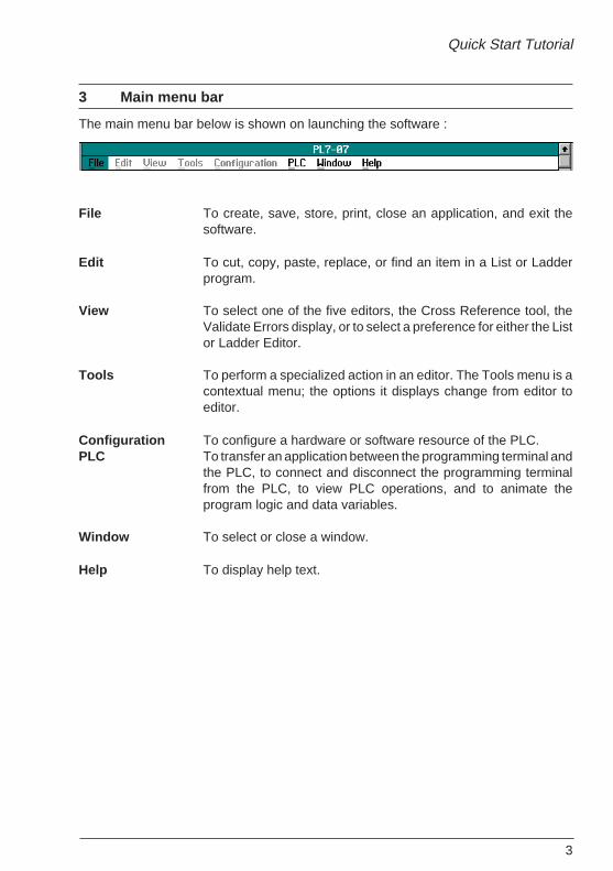
The main menu bar below is shown on launching the software :
File To create, save, store, print, close an application, and exit thesoftware.
Edit To cut, copy, paste, replace, or find an item in a List or Ladderprogram.
View To select one of the five editors, the Cross Reference tool, theValidate Errors display, or to select a preference for either the Listor Ladder Editor.
Tools To perform a specialized action in an editor. The Tools menu is acontextual menu; the options it displays change from editor toeditor.
Configuration To configure a hardware or software resource of the PLC.PLC To transfer an application between the programming terminal and
the PLC, to connect and disconnect the programming terminalfrom the PLC, to view PLC operations, and to animate theprogram logic and data variables.
Window To select or close a window.
Help To display help text.
4
4 Programming tutorial
4.1 Introduction
A program is made up of a series of instructions which are executed by the PLCprocessor in order to give commands to outputs based on input data read by the sameprocessor.
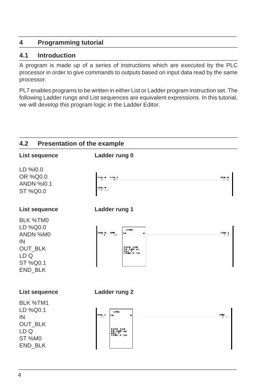
PL7 enables programs to be written in either List or Ladder program instruction set. Thefollowing Ladder rungs and List sequences are equivalent expressions. In this tutorial,we will develop this program logic in the Ladder Editor.
4.2 Presentation of the example
List sequence Ladder rung 0
LD %I0.0OR %Q0.0ANDN %I0.1ST %Q0.0
List sequence Ladder rung 1
BLK %TM0LD %Q0.0ANDN %M0INOUT_BLKLD QST %Q0.1END_BLK
List sequence Ladder rung 2
BLK %TM1LD %Q0.1INOUT_BLKLD QST %M0END_BLK
5
Quick Start Tutorial
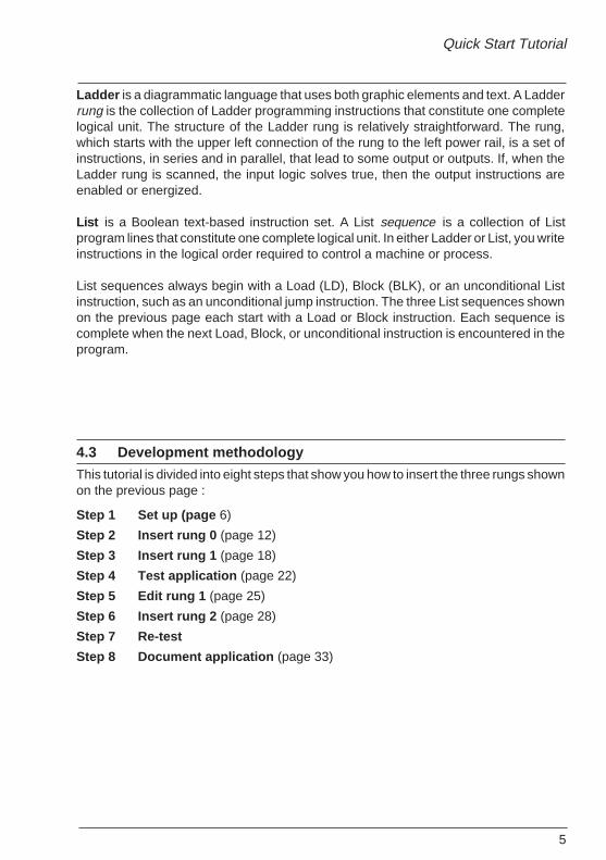
Ladder is a diagrammatic language that uses both graphic elements and text. A Ladderrung is the collection of Ladder programming instructions that constitute one completelogical unit. The structure of the Ladder rung is relatively straightforward. The rung,which starts with the upper left connection of the rung to the left power rail, is a set ofinstructions, in series and in parallel, that lead to some output or outputs. If, when theLadder rung is scanned, the input logic solves true, then the output instructions areenabled or energized.
List is a Boolean text-based instruction set. A List sequence is a collection of Listprogram lines that constitute one complete logical unit. In either Ladder or List, you writeinstructions in the logical order required to control a machine or process.
List sequences always begin with a Load (LD), Block (BLK), or an unconditional Listinstruction, such as an unconditional jump instruction. The three List sequences shownon the previous page each start with a Load or Block instruction. Each sequence iscomplete when the next Load, Block, or unconditional instruction is encountered in theprogram.
4.3 Development methodology
This tutorial is divided into eight steps that show you how to insert the three rungs shownon the previous page :
Step 1 Set up (page 6)
Step 2 Insert rung 0 (page 12)
Step 3 Insert rung 1 (page 18)
Step 4 Test application (page 22)
Step 5 Edit rung 1 (page 25)
Step 6 Insert rung 2 (page 28)
Step 7 Re-test
Step 8 Document application (page 33)
6
c:\>
c:\cd pl707
c:\PL707>pl707
(1)
Initial
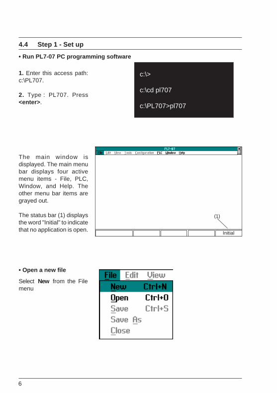
4.4 Step 1 - Set up
• Run PL7-07 PC programming software
1. Enter this access path:c:\PL707.
2. Type : PL707. Press<enter> .
The main window isdisplayed. The main menubar displays four activemenu items - File, PLC,Window, and Help. Theother menu bar items aregrayed out.
The status bar (1) displaysthe word "Initial" to indicatethat no application is open.
• Open a new file
Select New from the Filemenu
7
Quick Start Tutorial
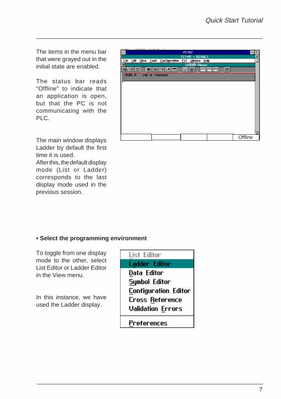
The items in the menu barthat were grayed out in theinitial state are enabled.
The status bar reads"Offline" to indicate thatan application is open,but that the PC is notcommunicating with thePLC.
The main window displaysLadder by default the firsttime it is used.After this, the default displaymode (List or Ladder)corresponds to the lastdisplay mode used in theprevious session.
• Select the programming environment
To toggle from one displaymode to the other, selectList Editor or Ladder Editorin the View menu.
In this instance, we haveused the Ladder display.
Offline
8
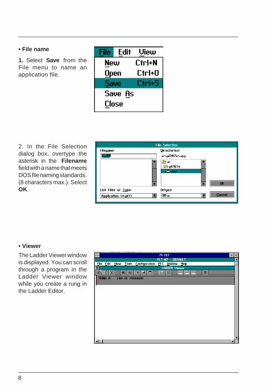
• File name
1. Select Save from theFile menu to name anapplication file.
2. In the File Selectiondialog box, overtype theasterisk in the Filenamefield with a name that meetsDOS file naming standards.(8 characters max.). SelectOK.
• Viewer
The Ladder Viewer windowis displayed. You can scrollthrough a program in theLadder Viewer windowwhile you create a rung inthe Ladder Editor.
9
Quick Start Tutorial
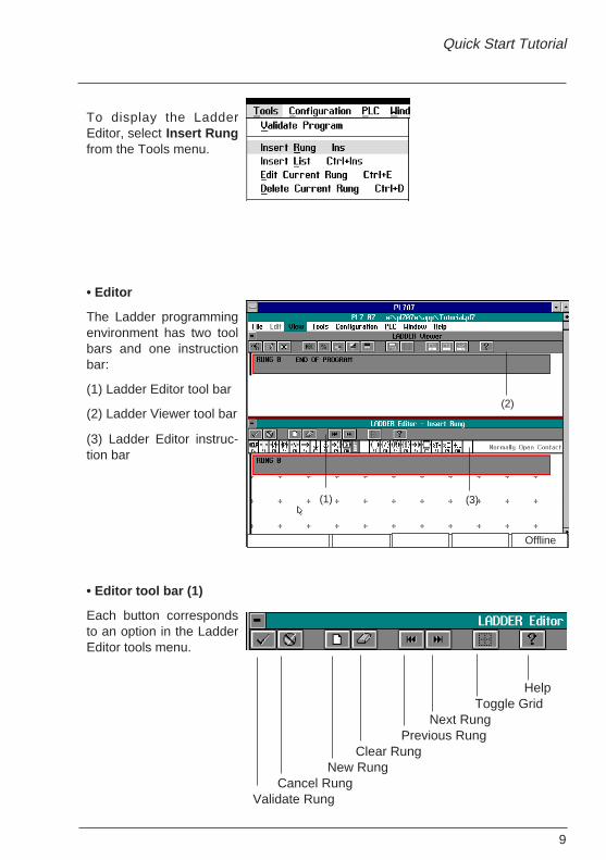
To display the LadderEditor, select Insert Rungfrom the Tools menu.
• Editor
The Ladder programmingenvironment has two toolbars and one instructionbar:
(1) Ladder Editor tool bar
(2) Ladder Viewer tool bar
(3) Ladder Editor instruc-tion bar
• Editor tool bar (1)
Each button correspondsto an option in the LadderEditor tools menu.
(2)
(1) (3)
HelpToggle Grid
Next RungPrevious Rung
Clear RungNew Rung
Cancel RungValidate Rung
Offline
10
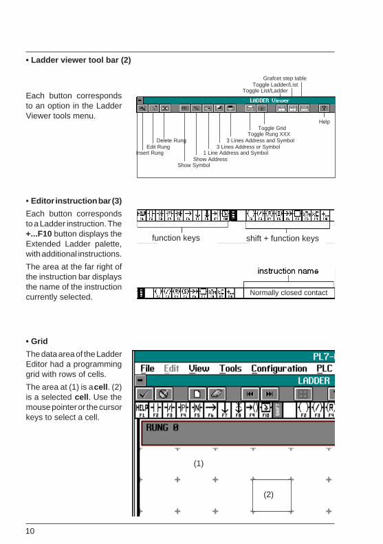
• Ladder viewer tool bar (2)
Each button correspondsto an option in the LadderViewer tools menu.
• Editor instruction bar (3)
Each button correspondsto a Ladder instruction. The+...F10 button displays theExtended Ladder palette,with additional instructions.
The area at the far right ofthe instruction bar displaysthe name of the instructioncurrently selected.
• Grid
The data area of the LadderEditor had a programminggrid with rows of cells.
The area at (1) is a cell . (2)is a selected cell . Use themouse pointer or the cursorkeys to select a cell.
Grafcet step tableToggle Ladder/List
Toggle List/Ladder
HelpToggle Grid
Toggle Rung XXXDelete Rung 3 Lines Address and Symbol
Edit Rung 3 Lines Address or SymbolInsert Rung 1 Line Address and Symbol
Show AddressShow Symbol
function keys shift + function keys
Normally closed contact
(2)
(1)
11
Quick Start Tutorial
Select
Place Cursor keys
Select Place
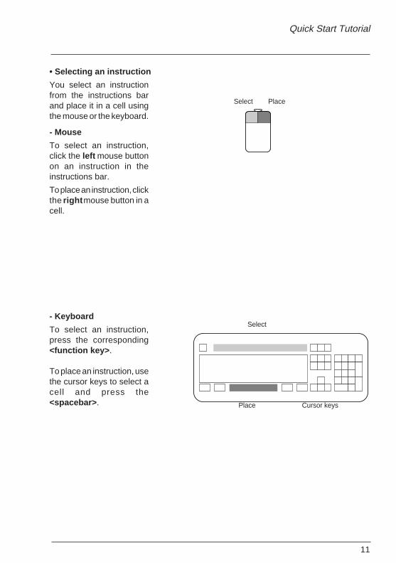
• Selecting an instruction
You select an instructionfrom the instructions barand place it in a cell usingthe mouse or the keyboard.
- Mouse
To select an instruction,click the left mouse buttonon an instruction in theinstructions bar.
To place an instruction, clickthe right mouse button in acell.
- Keyboard
To select an instruction,press the corresponding<function key> .
To place an instruction, usethe cursor keys to select acell and press the<spacebar> .

12
(1)
4.5 Step 2 - Insert rung 0
4.5-1 Insert instructions
1. Select a normally opencontact by clicking the leftmouse button on thecontact in the instruction baror by pressing <F2>.
2. Place a normally opencontact by clicking the rightmouse button in a cell. Or,select a cell with the cursorkeys and press the<spacebar> .
The selected cell is shownby a red line (1). The contactis shown in solid linesbeneath.
13
Quick Start Tutorial
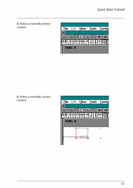
3. Select a normally closedcontact.
4. Place a normally closedcontact.
14
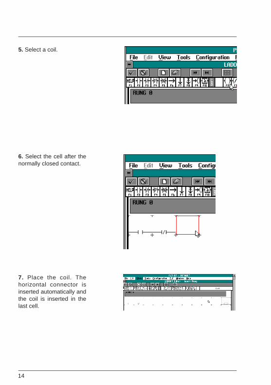
5. Select a coil.
6. Select the cell after thenormally closed contact.
7. Place the coil. Thehorizontal connector isinserted automatically andthe coil is inserted in thelast cell.
15
Quick Start Tutorial
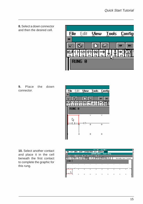
8. Select a down connectorand then the desired cell.
9. Place the downconnector.
10. Select another contactand place it in the cellbeneath the first contactto complete the graphic forthis rung.
16
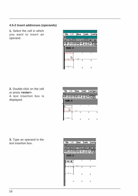
4.5-2 Insert addresses (operands)
1. Select the cell in whichyou want to insert anoperand.
2. Double-click on the cellor press <enter> .A text insertion box isdisplayed.
3. Type an operand in thetext insertion box.
17
Quick Start Tutorial
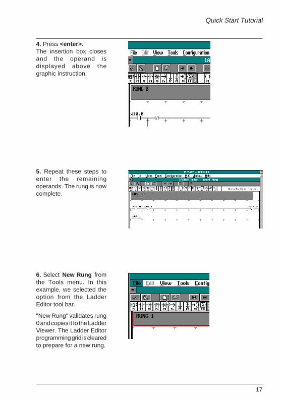
4. Press <enter> .The insertion box closesand the operand isdisplayed above thegraphic instruction.
5. Repeat these steps toenter the remainingoperands. The rung is nowcomplete.
6. Select New Rung fromthe Tools menu. In thisexample, we selected theoption from the LadderEditor tool bar.
"New Rung" validates rung0 and copies it to the LadderViewer. The Ladder Editorprogramming grid is clearedto prepare for a new rung.
18
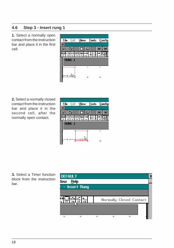
4.6 Step 3 - Insert rung 1
1. Select a normally opencontact from the instructionbar and place it in the firstcell.
2. Select a normally closedcontact from the instructionbar and place it in thesecond cell, after thenormally open contact.
3. Select a Timer functionblock from the instructionbar.
19
Quick Start Tutorial
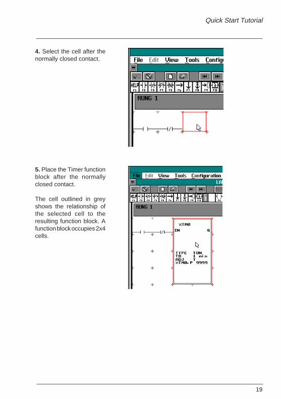
4. Select the cell after thenormally closed contact.
5. Place the Timer functionblock after the normallyclosed contact.
The cell outlined in greyshows the relationship ofthe selected cell to theresulting function block. Afunction block occupies 2x4cells.
20
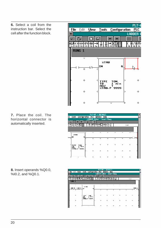
6. Select a coil from theinstruction bar. Select thecell after the function block.
7. Place the coil. Thehorizontal connector isautomatically inserted.
8. Insert operands %Q0.0,%I0.2, and %Q0.1.
21
Quick Start Tutorial
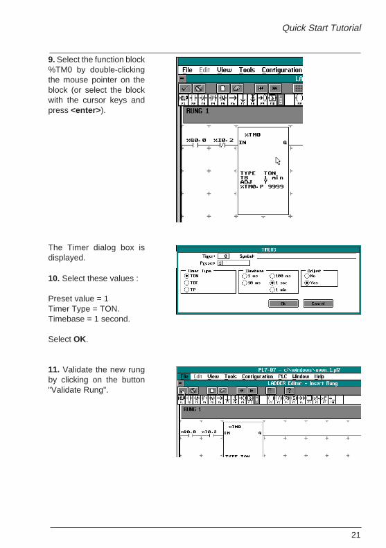
9. Select the function block%TM0 by double-clickingthe mouse pointer on theblock (or select the blockwith the cursor keys andpress <enter> ).
The Timer dialog box isdisplayed.
10. Select these values :
Preset value = 1Timer Type = TON.Timebase = 1 second.
Select OK.
11. Validate the new rungby clicking on the button"Validate Rung".
22
4.7 Step 4 - Test application
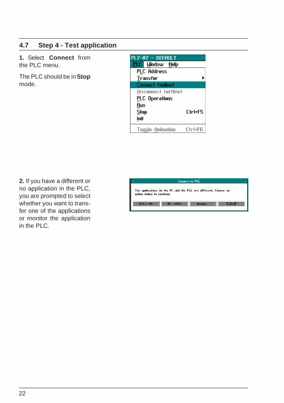
1. Select Connect fromthe PLC menu.
The PLC should be in Stopmode.
2. If you have a different orno application in the PLC,you are prompted to selectwhether you want to trans-fer one of the applicationsor monitor the applicationin the PLC.
23
Quick Start Tutorial
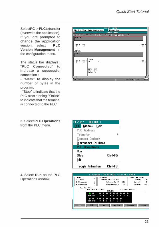
Select PC -> PLC to transfer(overwrite the application).If you are prompted tochange the applicationversion, select PLCVersion Management inthe configuration menu.
The status bar displays :"PLC Connected" toindicate a successfulconnection :- "Mem:" to display thenumber of bytes in theprogram,- "Stop" to indicate that thePLC is not running; "Online"to indicate that the terminalis connected to the PLC.
3. Select PLC Operationsfrom the PLC menu.
4. Select Run on the PLCOperations window.

24
An information dialog boxappears. Select OK to runthe PLC program.
The Run LED turns on.
5. Toggle the switch at input %I0.0 (1).
The LEDs for input %I0.0and for output %Q0.0 areturned on. Then the LED at%Q0.1 turns on.
6. Close the PLCOperations dialog box.
(1)It is advisable to use a 24VDC input simulator : TSX SIM 06 (for TSX 07 10 I/O), TSX SIM 09(for TSX 07 16 I/O) or TSX SIM 14 (for TSX 07 24 I/O)
25
Quick Start Tutorial
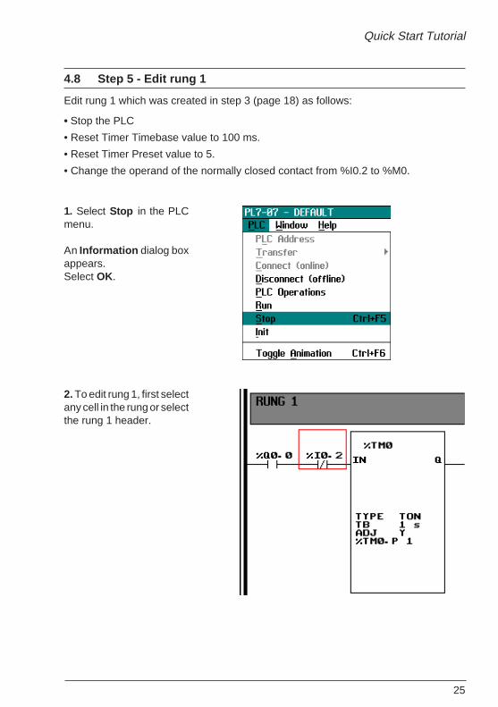
4.8 Step 5 - Edit rung 1
Edit rung 1 which was created in step 3 (page 18) as follows:
• Stop the PLC
• Reset Timer Timebase value to 100 ms.
• Reset Timer Preset value to 5.
• Change the operand of the normally closed contact from %I0.2 to %M0.
1. Select Stop in the PLCmenu.
An Information dialog boxappears.Select OK.
2. To edit rung 1, first selectany cell in the rung or selectthe rung 1 header.
26
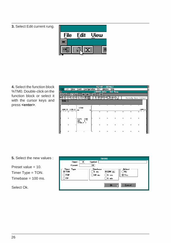
3. Select Edit current rung.
4. Select the function block%TM0. Double-click on thefunction block or select itwith the cursor keys andpress <enter> .
5. Select the new values :
Preset value = 10.
Timer Type = TON.
Timebase = 100 ms.
Select Ok.
27
Quick Start Tutorial
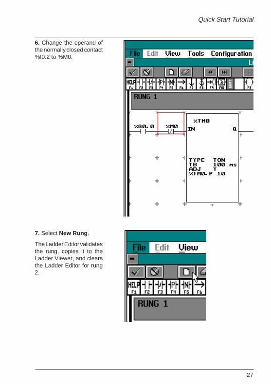
6. Change the operand ofthe normally closed contact%I0.2 to %M0.
7. Select New Rung .
The Ladder Editor validatesthe rung, copies it to theLadder Viewer, and clearsthe Ladder Editor for rung2.

28
4.9 Step 6 - Insert rung 2
1. Insert the graphic instruc-tions and the operands forrung 2.
2. Select the Timer functionblock.
Double-click on the functionblock with the mousepointer or press <enter> .
3. In the Timer dialog box,select these values :
Timer = 1
Preset value = 20.
Timer Type = TON.
Timebase = 100 ms.
Select Ok.
4. Select Validate Rung.
29
Quick Start Tutorial
4.10 Step 7 - Retest application
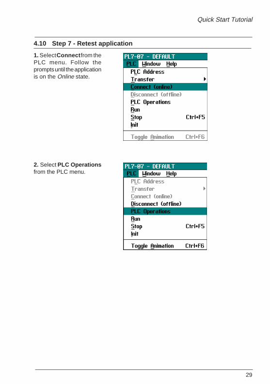
1. Select Connect from thePLC menu. Follow theprompts until the applicationis on the Online state.
2. Select PLC Operationsfrom the PLC menu.

30
3. Select Run from the PLCOperations window to runthe program on the PLC.
An information dialog boxappears. Select Ok to runthe PLC.
The Run LED turns on.
4. Toggle the switchconnected to input %I0.0.
5. Close the PLC Operationdialog box.
31
Quick Start Tutorial
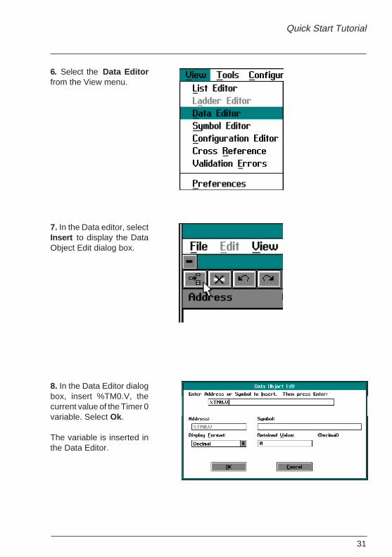
6. Select the Data Editorfrom the View menu.
7. In the Data editor, selectInsert to display the DataObject Edit dialog box.
8. In the Data Editor dialogbox, insert %TM0.V, thecurrent value of the Timer 0variable. Select Ok.
The variable is inserted inthe Data Editor.
32
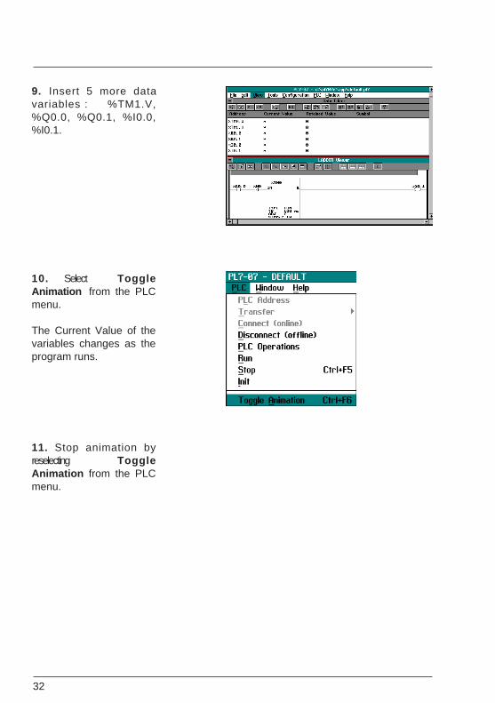
9. Insert 5 more datavariables : %TM1.V,%Q0.0, %Q0.1, %I0.0,%I0.1.
10. Select ToggleAnimation from the PLCmenu.
The Current Value of thevariables changes as theprogram runs.
11. Stop animation byreselecting ToggleAnimation from the PLCmenu.

33
Quick Start Tutorial
4.11 Step 8 - Document application
4.11-1 Insert comments
1. Stop the PLC.
2. Select a rung header, bydouble-clicking on it withthe mouse pointer, (orselect a rung header usingthe cursor keys and press<enter> ).
The rung header dialog boxis displayed.
3. Type a title for the rung inthe Title field, andcomments about the rungin the Comment field.
Select Ok.
The rung header displaysthe rung title and the firstline of comments.
34
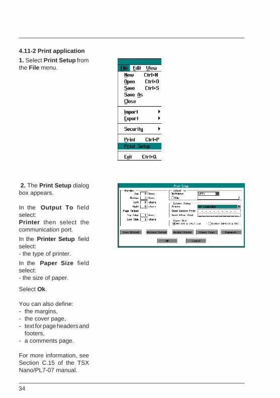
4.11-2 Print application
1. Select Print Setup fromthe File menu.
2. The Print Setup dialogbox appears.
In the Output To fieldselect:Printer then select thecommunication port.
In the Printer Setup fieldselect:- the type of printer.
In the Paper Size fieldselect:- the size of paper.
Select Ok.
You can also define:- the margins,- the cover page,- text for page headers and
footers,- a comments page.
For more information, seeSection C.15 of the TSXNano/PL7-07 manual.
35
Quick Start Tutorial
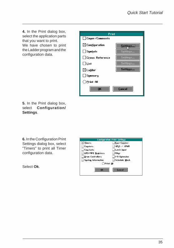
4. In the Print dialog box,select the application partsthat you want to print.We have chosen to printthe Ladder program and theconfiguration data.
5. In the Print dialog box,select Configuration/Settings .
6. In the Configuration PrintSettings dialog box, select"Timers" to print all Timerconfiguration data.
Select Ok.

36
7. In the Print dialog box,select Ladder/Settings .
8. In the Ladder PrintSettings dialog box:- Select All in the Rangefield to print all Ladderrungs.- Select the type of attribute.
Select OK.
9. In the Print dialog box,select Ok to begin printingthe file.
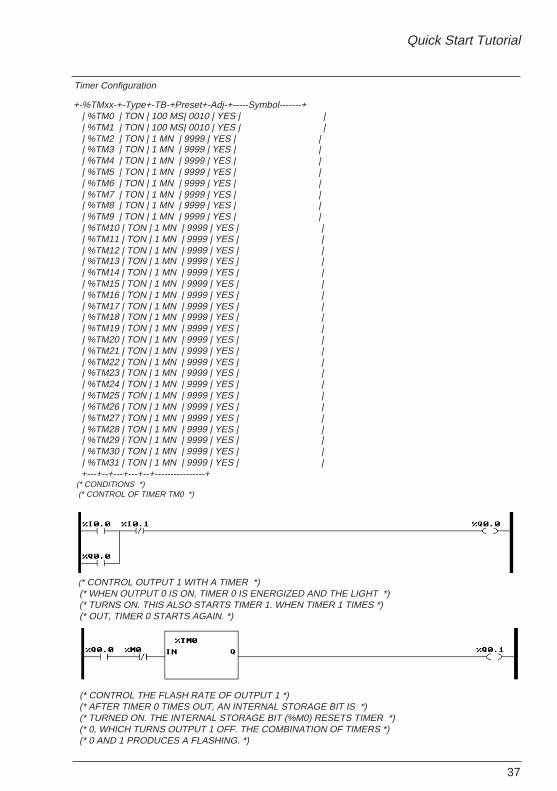
A partial printout is shownon the next page.
37
Quick Start Tutorial
Timer Configuration
+-%TMxx-+-Type+-TB-+Preset+-Adj-+-----Symbol-------+ | %TM0 | TON | 100 MS| 0010 | YES | | | %TM1 | TON | 100 MS| 0010 | YES | | | %TM2 | TON | 1 MN | 9999 | YES | | | %TM3 | TON | 1 MN | 9999 | YES | | | %TM4 | TON | 1 MN | 9999 | YES | | | %TM5 | TON | 1 MN | 9999 | YES | | | %TM6 | TON | 1 MN | 9999 | YES | | | %TM7 | TON | 1 MN | 9999 | YES | | | %TM8 | TON | 1 MN | 9999 | YES | | | %TM9 | TON | 1 MN | 9999 | YES | | | %TM10 | TON | 1 MN | 9999 | YES | | | %TM11 | TON | 1 MN | 9999 | YES | | | %TM12 | TON | 1 MN | 9999 | YES | | | %TM13 | TON | 1 MN | 9999 | YES | | | %TM14 | TON | 1 MN | 9999 | YES | | | %TM15 | TON | 1 MN | 9999 | YES | | | %TM16 | TON | 1 MN | 9999 | YES | | | %TM17 | TON | 1 MN | 9999 | YES | | | %TM18 | TON | 1 MN | 9999 | YES | | | %TM19 | TON | 1 MN | 9999 | YES | | | %TM20 | TON | 1 MN | 9999 | YES | | | %TM21 | TON | 1 MN | 9999 | YES | | | %TM22 | TON | 1 MN | 9999 | YES | | | %TM23 | TON | 1 MN | 9999 | YES | | | %TM24 | TON | 1 MN | 9999 | YES | | | %TM25 | TON | 1 MN | 9999 | YES | | | %TM26 | TON | 1 MN | 9999 | YES | | | %TM27 | TON | 1 MN | 9999 | YES | | | %TM28 | TON | 1 MN | 9999 | YES | | | %TM29 | TON | 1 MN | 9999 | YES | | | %TM30 | TON | 1 MN | 9999 | YES | | | %TM31 | TON | 1 MN | 9999 | YES | | +---+--+---+---+--+----------------+ (* CONDITIONS *) (* CONTROL OF TIMER TM0 *)
(* CONTROL OUTPUT 1 WITH A TIMER *) (* WHEN OUTPUT 0 IS ON, TIMER 0 IS ENERGIZED AND THE LIGHT *) (* TURNS ON. THIS ALSO STARTS TIMER 1. WHEN TIMER 1 TIMES *) (* OUT, TIMER 0 STARTS AGAIN. *)
(* CONTROL THE FLASH RATE OF OUTPUT 1 *) (* AFTER TIMER 0 TIMES OUT, AN INTERNAL STORAGE BIT IS *) (* TURNED ON. THE INTERNAL STORAGE BIT (%M0) RESETS TIMER *) (* 0, WHICH TURNS OUTPUT 1 OFF. THE COMBINATION OF TIMERS *) (* 0 AND 1 PRODUCES A FLASHING. *)

38