reaktor nuklir generasi iv - politeknik negeri jakarta nuklir generasi iv.pdf · inherent and...
TRANSCRIPT
Reaktor Nuklir Generasi IVDr. Eng. Pribadi Mumpuni Adhi
Politeknik Negeri Jakarta 2018
1

Tujuan• Sustainability - Providing sustainable energy that meets clean air
objectives, gives long-term availability of systems and effective fuel utilization for worldwide energy production. Also to minimize and manage waste, thereby improving protection for the public and the environment.
• Economics -Compared to the other energy resources it should have life cycle cost advantage, and the level of financial is comparable to other energy projects.
• Safety - The reactors will excel in safety and reliability; there will be very low likelihood of core damage, along with minimized severity in the case of an accident. Emergency response systems will be optimized and will not require offsite emergency response.
• Proliferation Resistance - The reactor's use and processing of nuclear fuel will increase the assurance of materials being unattractive for theft and terrorism, along with a physical protection system to prevent the fuel from ending up in the wrong hands.
2
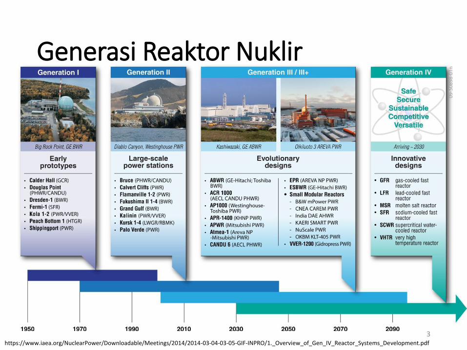
Generasi Reaktor Nuklir
3https://www.iaea.org/NuclearPower/Downloadable/Meetings/2014/2014-03-04-03-05-GIF-INPRO/1._Overview_of_Gen_IV_Reactor_Systems_Development.pdf
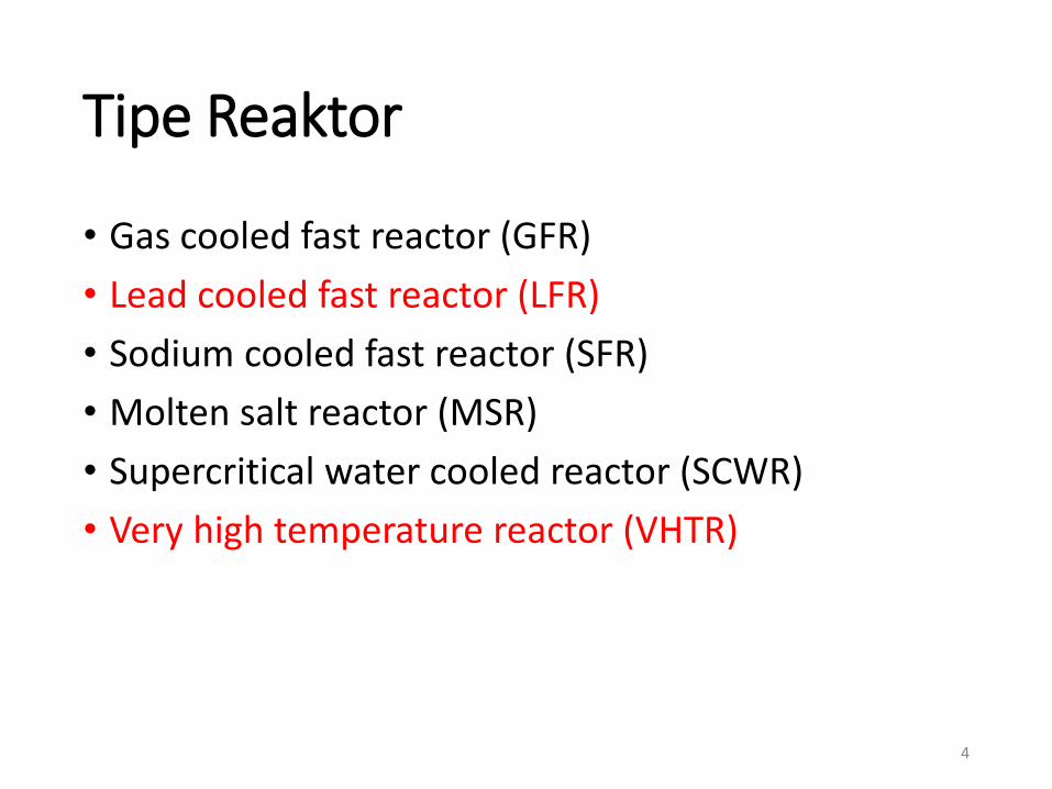
Tipe Reaktor
• Gas cooled fast reactor (GFR)
• Lead cooled fast reactor (LFR)
• Sodium cooled fast reactor (SFR)
• Molten salt reactor (MSR)
• Supercritical water cooled reactor (SCWR)
• Very high temperature reactor (VHTR)
4
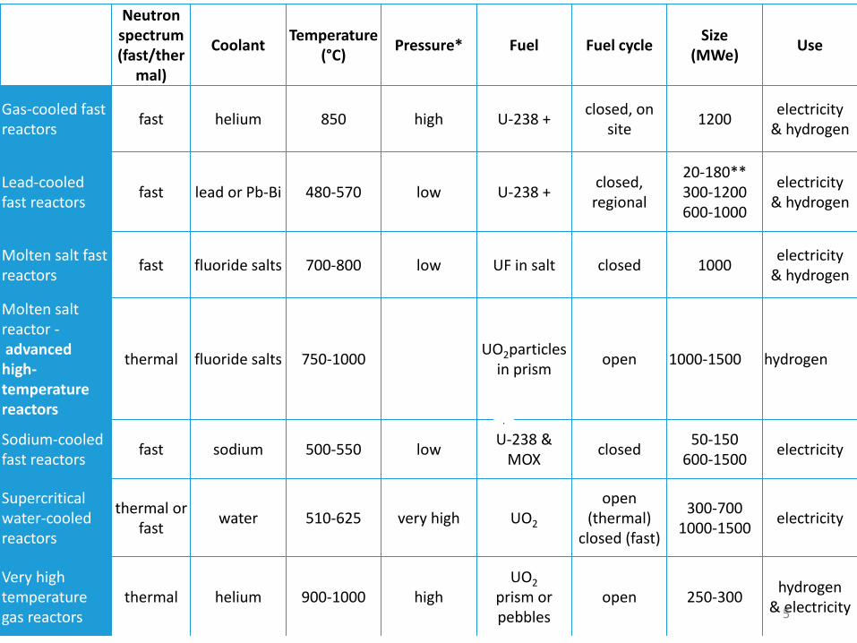
Neutron spectrum(fast/ther
mal)
CoolantTemperature
(°C)Pressure* Fuel Fuel cycle
Size(MWe)
Use
Gas-cooled fast reactors
fast helium 850 high U-238 +closed, on
site1200
electricity& hydrogen
Lead-cooled fast reactors
fast lead or Pb-Bi 480-570 low U-238 +closed, regional
20-180**300-1200600-1000
electricity& hydrogen
Molten salt fast reactors
fast fluoride salts 700-800 low UF in salt closed 1000electricity
& hydrogen
Molten salt reactor -advanced high-temperature reactors
thermal fluoride salts 750-1000UO2particles
in prismopen 1000-1500 hydrogen
Sodium-cooled fast reactors
fast sodium 500-550 lowU-238 &
MOXclosed
50-150600-1500
electricity
Supercritical water-cooled reactors
thermal or fast
water 510-625 very high UO2
open (thermal)
closed (fast)
300-7001000-1500
electricity
Very high temperature gas reactors
thermal helium 900-1000 highUO2
prism or pebbles
open 250-300hydrogen
& electricity5
.
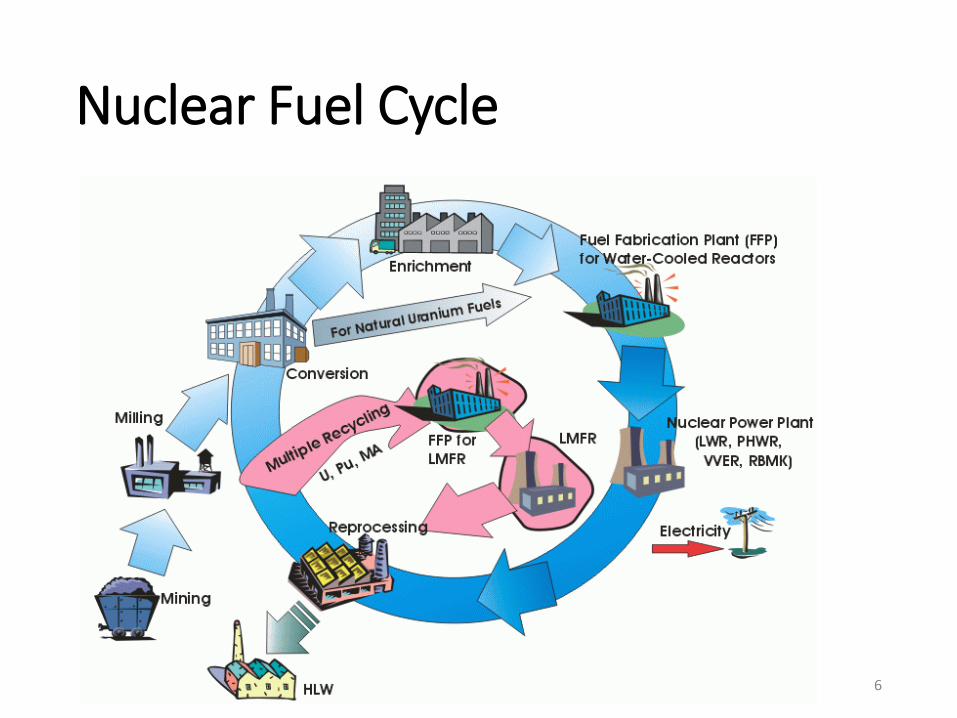
Nuclear Fuel Cycle
6
Lead-cooled Fast Reactor
7

Inherent and Passive Safety Features of LFR
◼ Larger scattering cross section
→ High neutron confinement performance, Better neutron economy, Large fuel P/D
◼ High performance of Pb-208 due to low capture cross section (See GLABAL 2011 Paper No.398761, Pb-208 is the final stable nucleus in Th decay chain)
◼ Pb-206 is low activation coolant (See ICONE-8385)
◼ Heavy nuclide mass → Low moderating power → Hard spectrum → Negative coolant void coefficient, Better MA burning capability
◼ Low burn-up reactivity swing → Long life core
◼ Higher boiling temperatures → No coolant boiling in transient conditions
8
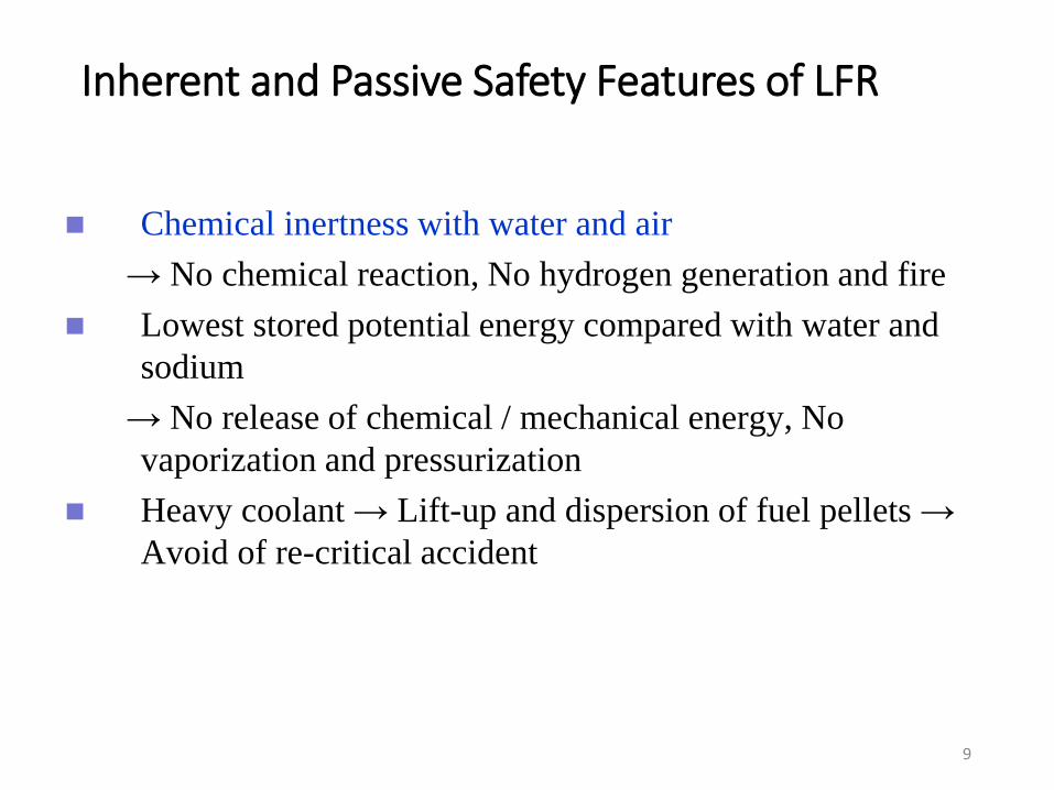
Inherent and Passive Safety Features of LFR
◼ Chemical inertness with water and air
→ No chemical reaction, No hydrogen generation and fire
◼ Lowest stored potential energy compared with water and
sodium
→ No release of chemical / mechanical energy, No
vaporization and pressurization
◼ Heavy coolant → Lift-up and dispersion of fuel pellets →
Avoid of re-critical accident
9
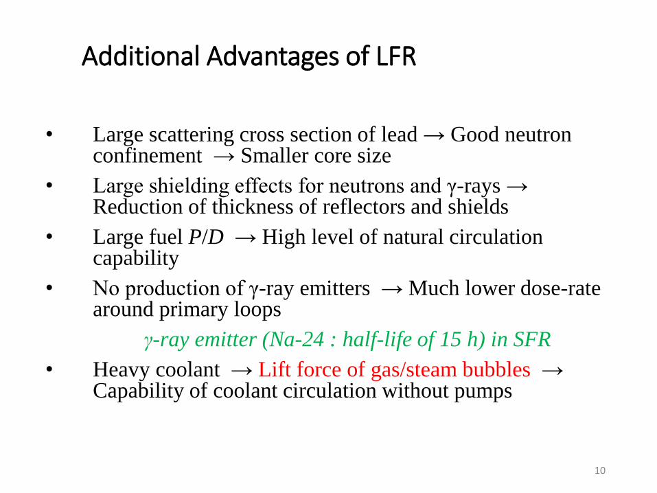
Additional Advantages of LFR
• Large scattering cross section of lead → Good neutron confinement → Smaller core size
• Large shielding effects for neutrons and γ-rays → Reduction of thickness of reflectors and shields
• Large fuel P/D → High level of natural circulation capability
• No production of γ-ray emitters → Much lower dose-rate around primary loops
γ-ray emitter (Na-24 : half-life of 15 h) in SFR
• Heavy coolant → Lift force of gas/steam bubbles → Capability of coolant circulation without pumps
10
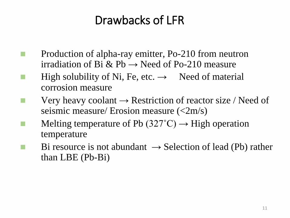
Drawbacks of LFR
◼ Production of alpha-ray emitter, Po-210 from neutron irradiation of Bi & Pb → Need of Po-210 measure
◼ High solubility of Ni, Fe, etc. → Need of material corrosion measure
◼ Very heavy coolant → Restriction of reactor size / Need of seismic measure/ Erosion measure (<2m/s)
◼ Melting temperature of Pb (327˚C) → High operation temperature
◼ Bi resource is not abundant → Selection of lead (Pb) rather than LBE (Pb-Bi)
11

◆Long life core
◆ Small reactors are constructed in factories
of the nuclear energy park,
◆Transported to the site, and deployed.
◆Sealed reactor vessel without being opened
at the site.
◆Excellent proliferation resistance in
refueling
-At the end of the reactor life, it is replaced by
a new one. The old one is shipped to the
nuclear energy park.
◆Environment
-No radioactive waste left at the site. (Site is
free from waste problems.)
Concept of LSPR studied in 1990s (LBE-cooled long-life Safe Simple Small Portable
Proliferation resistant Reactor)
LSPR
Core
Steam generatorControl rod
Pump
12
1
13
14
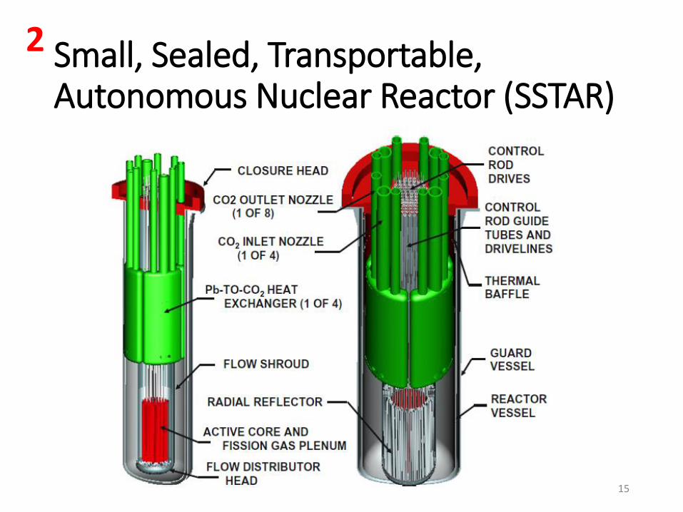
Small, Sealed, Transportable, Autonomous Nuclear Reactor (SSTAR)
15
2

Development Phases of Heavy Liquid Metal Coolant
(HLMC) in Russia
1951
The first Pb-Bi
circulation test
facility (IPPE) 1963 – The first nuclear submarine
K-27 (Project 645 using Pb-Bi
coolant
2013
Development of SVBR-100 and
BREST-OD-300
using Pb-Bi and Pb coolants is
continued
1971 – Nuclear submarines
(Projects 705 and 705K)
using Pb-Bi coolant
3
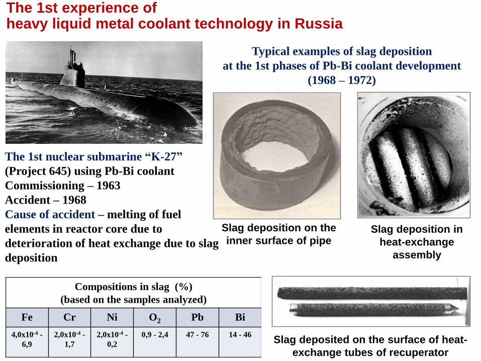
The 1st experience of heavy liquid metal coolant technology in Russia
The 1st nuclear submarine “K-27”
(Project 645) using Pb-Bi coolant
Commissioning – 1963
Accident – 1968
Cause of accident – melting of fuel
elements in reactor core due to
deterioration of heat exchange due to slag
deposition
Typical examples of slag deposition
at the 1st phases of Pb-Bi coolant development
(1968 – 1972)
Slag deposited on the surface of heat-
exchange tubes of recuperator
Slag deposition on the
inner surface of pipeSlag deposition in
heat-exchange
assembly
Compositions in slag (%)
(based on the samples analyzed)
Fe Cr Ni O2 Pb Bi
4,0x10⁻⁴ -
6,9
2,0x10⁻⁴ -
1,7
2,0x10⁻⁴ -
0,2
0,9 - 2,4 47 - 76 14 - 46
Reaktor DayaExperimental (RDE)
18
Download Materi Kuliah
http://mesin.pnj.ac.id/news/index/1802/Pribadi.html
19