rechargeable products lead-acid battery · 1 2 co nte s introduction the new vision ct series of...
TRANSCRIPT

Center Power Industrial Park Tongfu Industrial DistrictDapeng TownPC 518120 Shenzhen China
Tel +86-755-8431 8088 Fax +86-755-8431 8700
E-mail salesvision-battcom Website httpwwwvision-battcom
(Edition Apr 2008)
C T Front Terminal Type
Series
wwwvision-battcom
Shenzhen Center Power Tech Co Ltd
VISION
Rechargeable Products
Lead-Acid Battery
On
e o
f th
e l
arg
est
Seale
d L
ead A
cid
Batt
ery
man
ufa
ctu
rers
in t
he w
orl
d
Products Guide
21
IntroductionContents
The new VISION CT series of VRLA batteries has been specially
designed for use in telecom systems With proven compliance to
the most rigorous international standards Such as IEC60896-
2122 BS6290-4 Eurobat Guide VISION CT series batteries are
recognized as the best ones for telecom applications With front
access terminals its easy for installing and taking voltage
readings during service The battery container and cover made
from V0 class flame retardant ABS amp with thick walls offer the
battery with high mechanical strength and safety service features
VISION CT delivers high performance while occupying less space
than conventional battery series
Shenzhen Center Power Tech CoLtd has more than 15 years
experience in the manufacturing of VRLA batteries
This product guide covers the VISION CT Front Terminal series and
is designed to help users select the appropriate battery for
particular applications Technical information includes detailed
discharge performance data for each unit and advice on calculating
the correct battery size
The new VISION CT Front Terminal range of valve regulated lead
acid batteries has been designed specifically for use in applications
where demand the highest levels of security and reliability With
proven compliance to international standards VISION CT is
recognized as one of the best battery series for TelecomIT
applications
The adoption of gas recombination technology enables lead acid
batteries be manufactured in sealed design and maintenance-free
This Technology provides the user with the freedom to use lead
acid batteries in a wide range of applications and batteries can be
installed in any locations
The VISION CT Front Terminal batteries are suitable for 19rdquo 23rdquo
and ETSI racking give users the benefit of increased energy
density With all electrical connections at the front installation and
inspection are simpler and quicker
wwwvision-battcom
Features and benefits
IEC60896-2122
BS6290-4
Eurobat Guide
IEC 707 FV0
DOT 167
Introduction 1
Features and benefitsStandards Applications 2
Range Summary Position of terminals 3
Constraction 4
Performance Data 5-8
Technology 9
Operating Characteristics 10
Operating Instructions andGuidelines 11
Installation and Commissioning Charge 12 12
Battery Storage 13
Battery Accommodation 14
Thick pasted plates with high quality lead-
tin-calcium alloy grids for long service life
Centralized venting system for gas
ventilation
Rope handles for handing and installation
convenience
Design life 12+ years
Easy installation
Robust copper terminals providing high
conductivity easy connection
Front access terminals for easy and quick
connection
VISION Rechargeable Products
Sealed Lead Acid Battery
Standards
Communication equipment
Uninterruptible power supplies
Telecommunication systems
Electronic cash registers
Microprocessor based office machines
Other standby power supplies
Applications
CT12-125X CT12-140X CT12-180XCT12-150X
TYPE NominalVoltage(V)
Capacity Terminal Wt(lbs)
oto 18Vpc10hr25 C L(mm) L(inch) W(mm) H(mm) W(inch) H(inch) TH(mm) TH(inch) Wt(Kg)
CT Range Summary
Position of terminals
CT12-50X 12 50 277 109 106 417 222 874 229 902 M6 173 381
CT12-80X 12 80 564 222 115 453 189 744 189 744 M8 282 622
CT12-100X 12 100 508 200 110 433 223 878 238 937 M6 325 716
CT12-105X 12 105 395 156 110 433 286 113 293 115 M8 350 772
CT12-125X 12 125 436 172 108 425 317 125 317 125 M8 410 904
CT12-140X 12 140 552 217 110 433 288 113 295 116 M8 490 108
CT12-150X 12 150 561 221 105 413 316 124 316 124 M8 504 111
CT12-180X 12 180 546 215 125 492 317 125 323 127 M8 600 132
8
CT12-50X CT12-80X CT12-105XCT12-100X
3 4
1 Heavy duty plates sophisticated electronic equipment A proven
technology that is 100 factory tested to Heavier and thicker plates are pasted from
ensure long life and performanceboth sides for added durability and a twelve-
yeardesign life Scientific grids designed to
resist corrosion and prolong life special 5 Tough flame retardant cell box
positive grid alloy with pure lead low Thick-wall reinforced flame retardant calcium and high tin delivers quick high-rate (RATED UL94 V0 28 LOI) ABS resists power Balanced negative plates ensure bulging and meets safety requirements optimum recombination efficiency highly resistant to shock and vibration
Tank formed plates ensure full and uniform Special reinforced design protects battery
plate formation optimizing cell voltage while providing added heat dissipation
balance and capabilities
performance
6 Self-regulating relief valve
2 Advanced Absorbed Glass Mat (AGM) Low pressure self-return EPDM Rubber valve
technology prevents ingress of atmospheric oxygen
Utilizes special micro-porous separators to maximizes gas recombination efficiency and
absorb all the electrolyte lowering internal minimizes gassing Self-sealing valves are
resistance increasing power maximizing 100 factory tested to prevent premature
space utilization and eliminating leaks for dry-out for dependable battery service
safe installation and storage Flame arrestors are installed on all flame-
retardant batteries for added safetyPuncture resistant glass mat separators
lowers internal resistance for superior high-
rate power while protecting against failures 7 Lifting handles
and shorts for maximum life All the batteries in the range are provided
with rope handles
3 High conductivity connectors and terminal
Tin plated copper threaded insert posts for
easy installation and maintenance ensuring
the highest current-carrying capacities
Strong copper threaded insert terminals
providing high conductivity and power The
front mounted terminal minimises
installation work and makes maintenance
very convenient during service
4 High reliable terminal sealing
Epoxy post seal design eliminates post leaks
extending battery life and protecting
Construction
Unitmm
19
M8
45
65
(No
te)T
he a
bo
ve c
ha
racte
risti
cs
da
ta a
re a
ve
rag
e v
alu
es
ob
tain
ed w
ith
in t
hre
e c
ha
rge
dis
ch
arg
e c
ycle
s n
ot
the
mim
imu
m v
alu
es
oC
onsta
nt C
urr
ent D
ischarg
e (
Am
pere
s )
at 2
0C to
16
0 v
olts p
er
cell
Ba
tte
ry T
yp
e
15
min
2
0m
in
25
min
30
min
35
min
4
0m
in 4
5m
in 5
0m
in
55
min
6
0m
in
1
h
1
5h
2
h
2
5h
3
h
4
h
5h
6h
7
h
8h
9
h
10
h
1
2h
2
4h
CT
12-5
0X
109
882
729
637
576
518
474
440
405
376
352
249
197
166
145
112
92
678
568
561
055
150
443
522
7
CT
12-8
0X
174
141
117
102
921
828
758
704
648
601
563
398
315
265
232
180
148
126
110
97
588
280
769
736
3
CT
12-1
00X
218
176
146
127
115
103
948
880
810
752
704
498
394
332
291
225
185
157
137
122
110
101
87
245
5
CT
12-1
05X
229
185
153
134
121
109
996
924
850
789
739
522
414
348
305
236
194
165
144
128
116
106
91
547
7
CT
12-1
25X
255
211
175
153
138
123
112
103
958
899
850
601
477
402
352
279
235
200
174
156
141
129
111
58
1
CT
12-1
40X
305
257
210
181
162
144
1305
120
110
101
944
669
531
448
393
313
265
225
196
174
157
144
124
64
8
CT
12-1
50X
270
224
196
178
160
1473
137
127
118
111
791
631
535
471
365
302
253
217
191
170
154
133
69
3
CT
12-1
80X
300
249
218
197
175
158
145
134
125
118
845
678
577
513
98
33
281
247
221
200
184
159
82
8
oC
onsta
nt C
urr
ent D
ischarg
e (
Am
pere
s )
at 2
0C to
16
5 v
olts p
er
cell
Ba
tte
ry T
yp
e
15
min
2
0m
in
25
min
30
min
35
min
4
0m
in 4
5m
in 5
0m
in
55
min
6
0m
in
1
h
1
5h
2
h
2
5h
3
h
4
h
5h
6h
7
h
8h
9
h
10
h
1
2h
2
4h
CT
12-5
0X
101
827
691
609
555
500
459
427
394
367
345
244
194
163
143
111
91
978
068
160
754
950
343
422
6
CT
12-8
0X
161
133
111
98
887
800
734
683
631
588
552
391
310
261
229
178
147
125
109
97
187
980
569
536
2
CT
12-1
00X
201
165
138
122
111
100
918
854
788
735
69
488
387
326
286
222
184
156
137
122
110
101
87
245
5
CT
12-1
05X
212
174
146
128
117
105
965
897
828
771
724
513
407
343
301
234
193
164
143
128
116
106
91
547
7
CT
12-1
25X
237
200
167
147
134
120
109
101
941
885
838
594
471
398
349
277
233
198
173
154
140
128
111
57
6
CT
12-1
40X
280
239
198
173
156
139
127
117
107
993
926
658
523
443
389
311
264
224
195
173
156
143
123
64
4
CT
12-1
50X
252
212
187
171
155
143
133
123
116
109
776
619
525
462
358
296
248
214
189
169
153
132
68
9
CT
12-1
80X
285
239
211
192
171
155
143
132
123
116
832
667
569
503
394
328
280
245
219
199
183
158
82
4
Pe
rfo
rma
nce
Da
ta
Am
pe
res
Co
nsta
nt
Cu
rre
nt
Dis
ch
arg
e p
erf
orm
an
ce
oC
onsta
nt C
urr
ent D
ischarg
e (
Am
pere
s )
at 2
0C to
17
5 v
olts p
er
cell
Ba
tte
ry T
yp
e
15
min
2
0m
in
25
min
30
min
35
min
4
0m
in 4
5m
in 5
0m
in
55
min
6
0m
in
1
h
1
5h
2
h
2
5h
3
h
4
h
5h
6h
7
h
8h
9
h
10
h
1
2h
2
4h
CT
12-5
0X
85
716
61
55
512
46
429
401
373
350
331
235
186
157
138
108
90
677
167
560
254
650
143
322
5
CT
12-8
0X
136
115
98
88
816
741
686
642
597
560
529
376
299
253
222
174
145
123
108
96
487
480
269
236
1
CT
12-1
00X
169
143
123
110
102
927
857
802
746
699
661
469
373
315
277
217
181
154
135
120
109
100
86
345
0
CT
12-1
05X
178
151
130
117
108
978
902
842
783
734
69
49
393
332
292
228
19
162
141
126
114
105
90
747
3
CT
12-1
25X
201
177
152
137
127
114
105
97
91
86
81
58
461
390
343
272
23
195
171
152
138
126
109
56
7
CT
12-1
40X
229
203
173
155
143
129
118
110
102
95
89
64
510
434
383
307
261
221
192
171
154
141
122
63
5
CT
12-1
50X
235
214
186
168
157
143
133
125
116
109
103
74
591
503
444
344
284
240
208
184
166
151
130
68
0
CT
12-1
80X
285
254
218
196
181
163
149
138
127
118
111
80
644
550
488
385
323
276
242
217
197
181
156
81
5
oC
onsta
nt C
urr
ent D
ischarg
e (
Am
pere
s )
at 2
0C to
18
0 v
olts p
er
cell
Ba
tte
ry T
yp
e
15
min
2
0m
in
25
min
30
min
35
min
4
0m
in 4
5m
in 5
0m
in
55
min
6
0m
in
1
h
1
5h
2
h
2
5h
3
h
4
h
5h
6h
7
h
8h
9
h
10
h
1
2h
2
4h
CT
12-5
0X
770
660
575
524
490
446
414
388
362
341
324
230
183
155
136
107
90
076
767
160
054
450
043
222
5
CT
12-8
0X
122
105
92
83
781
712
661
621
580
55
518
368
293
248
218
172
144
123
107
96
087
180
069
136
0
CT
12-1
00X
153
132
115
105
98
893
827
776
724
68
647
460
367
310
273
215
18
153
134
120
109
100
86
345
0
CT
12-1
05X
161
139
122
111
104
944
871
815
761
716
679
483
385
326
287
226
189
161
141
126
114
105
90
747
3
CT
12-1
25X
183
165
144
131
123
111
102
95
89
841
800
570
455
386
34
270
228
194
169
151
136
125
108
56
3
CT
12-1
40X
203
185
161
147
137
124
114
106
98
922
870
625
503
429
38
305
26
220
191
170
153
140
121
63
0
CT
12-1
50X
210
195
172
158
149
137
127
120
112
105
100
717
575
491
434
337
278
235
205
182
164
150
130
67
5
CT
12-1
80X
261
238
207
188
176
158
145
135
125
116
109
785
633
541
48
381
321
274
240
215
196
180
155
81
0
oC
onsta
nt C
urr
ent D
ischarg
e (
Am
pere
s )
at 2
0C to
17
0 v
olts p
er
cell
Ba
tte
ry T
yp
e
15
min
2
0m
in
25
min
30
min
35
min
4
0m
in 4
5m
in 5
0m
in
55
min
6
0m
in
1
h
1
5h
2
h
2
5h
3
h
4
h
5h
6h
7
h
8h
9
h
10
h
1
2h
2
4h
CT
12-5
0X
93
771
65
58
533
48
444
414
384
359
338
240
190
161
141
110
91
377
667
860
554
850
243
322
6
CT
12-8
0X
149
123
104
93
852
771
710
663
614
574
54
383
305
257
226
176
146
124
109
96
887
780
469
436
2
CT
12-1
00X
185
154
131
116
107
966
889
828
767
717
676
479
381
321
282
220
183
155
136
121
109
100
86
345
0
CT
12-1
05X
195
162
137
122
112
101
933
870
806
753
71
50
399
337
296
231
192
163
142
127
115
105
90
747
3
CT
12-1
25X
219
188
160
142
131
117
107
99
92
87
83
59
466
394
346
275
232
197
172
153
139
127
110
57
2
CT
12-1
40X
254
221
186
164
150
134
122
113
104
97
91
65
516
438
386
309
263
223
194
172
155
142
123
63
9
CT
12-1
50X
233
199
178
164
149
138
129
120
112
106
76
605
514
453
351
29
244
211
187
167
152
131
68
4
CT
12-1
80X
269
228
203
187
167
152
140
130
121
114
82
656
560
495
389
326
278
244
218
198
182
157
81
9
(No
te)T
he a
bo
ve c
ha
racte
risti
cs
da
ta a
re a
ve
rag
e v
alu
es
ob
tain
ed w
ith
in t
hre
e c
ha
rge
dis
ch
arg
e c
ycle
s n
ot
the
mim
imu
m v
alu
es
Pe
rfo
rma
nce
Da
ta
Wa
tts
pe
r ce
ll
Co
nsta
nt
Po
we
r D
isch
arg
e p
erf
orm
an
ce
(No
te)T
he a
bo
ve c
ha
racte
risti
cs
da
ta a
re a
ve
rag
e v
alu
es
ob
tain
ed w
ith
in t
hre
e c
ha
rge
dis
ch
arg
e c
ycle
s n
ot
the
mim
imu
m v
alu
es
Ba
tte
ry T
yp
e
15
min
2
0m
in
25
min
30
min
35
min
4
0m
in 4
5m
in 5
0m
in
55
min
6
0m
in
1
h
1
5h
2
h
2
5h
3
h
4
h
5h
6h
7
h
8h
9
h
10
h
1
2h
2
4h
CC
T12-5
0X
190
159
135
121
111
100
920
856
790
735
69
489
389
327
285
223
185
156
135
119
107
96
883
142
7
CT
12-8
0X
304
255
217
193
178
160
147
137
126
117
110
781
622
522
456
356
296
249
215
190
171
155
133
68
4
CT
12-1
00X
380
319
271
242
223
201
184
171
158
147
138
978
777
653
57
446
371
312
270
238
214
194
166
85
6
CT
12-1
05X
399
335
285
254
234
211
194
180
166
155
145
103
816
685
598
467
389
327
283
250
224
204
175
89
9
CT
12-1
25X
450
376
314
277
252
226
207
192
178
167
157
113
908
760
661
524
442
377
331
296
269
248
213
109
CT
12-1
40X
488
413
343
301
273
246
226
210
194
182
171
124
100
851
752
594
499
425
372
332
301
276
237
122
CT
12-1
50X
432
365
325
298
269
247
230
214
201
190
142
118
100
881
690
576
483
416
366
327
296
254
131
CT
12-1
80X
525
443
393
360
323
296
274
254
238
225
164
134
112
98
768
641
545
477
425
385
353
303
156
Ba
tte
ry T
yp
e
15
min
2
0m
in
25
min
30
min
35
min
4
0m
in 4
5m
in 5
0m
in
55
min
6
0m
in
1
h
1
5h
2
h
2
5h
3
h
4
h
5h
6h
7
h
8h
9
h
10
h
1
2h
2
4h
CT
12-5
0X
179
151
129
116
107
966
888
827
765
714
671
480
384
323
282
221
184
155
134
118
106
96
682
942
7
CT
12-8
0X
287
242
207
185
171
155
143
133
123
114
107
767
615
517
452
354
295
248
215
190
170
155
133
68
3
CT
12-1
00X
358
303
259
232
214
193
177
165
153
142
134
959
768
646
565
442
368
310
269
237
213
194
166
85
6
CT
12-1
05X
376
318
271
243
224
203
187
174
161
150
141
101
807
679
593
464
386
325
282
249
224
204
175
89
9
CT
12-1
25X
428
361
304
269
246
221
203
188
174
163
154
111
893
750
654
520
439
375
329
294
267
246
211
109
CT
12-1
40X
464
395
330
291
265
239
220
205
190
178
168
122
988
840
742
587
494
421
369
329
299
275
236
121
CT
12-1
50X
420
356
318
292
264
243
227
211
199
188
141
117
991
872
684
571
479
413
363
325
294
252
130
CT
12-1
80X
503
426
380
349
314
288
268
249
234
221
162
132
111
97
761
636
541
473
423
383
351
302
155
Ba
tte
ry T
yp
e
15
min
2
0m
in
25
min
30
min
35
min
4
0m
in 4
5m
in 5
0m
in
55
min
6
0m
in
1
h
1
5h
2
h
2
5h
3
h
4
h
5h
6h
7
h
8h
9
h
10
h
1
2h
2
4h
CT
12-5
0X
158
135
116
105
979
889
822
769
715
672
635
462
375
316
277
217
181
153
133
117
106
96
282
642
5
CT
12-8
0X
252
216
186
168
156
142
131
123
115
108
102
74
600
506
443
347
290
245
212
188
169
154
132
68
0
CT
12-1
00X
316
270
233
211
196
178
165
154
143
134
127
923
750
632
554
434
362
305
265
235
211
192
165
84
8
CT
12-1
05X
331
284
245
222
206
187
173
162
150
141
133
968
787
664
582
456
380
321
278
246
221
202
173
89
0
CT
12-1
25X
383
333
283
252
232
209
192
179
166
156
147
107
864
729
639
510
432
369
323
289
263
242
208
107
CT
12-1
40X
418
358
304
272
250
226
208
194
181
171
162
118
963
819
723
574
485
414
363
324
295
271
232
120
CT
12-1
50X
440
394
337
303
280
254
234
219
205
194
184
138
115
972
853
669
559
469
405
357
320
290
249
128
CT
12-1
80X
517
458
393
354
328
298
275
257
239
224
212
155
127
108
950
747
625
533
466
417
378
348
298
153
Ba
tte
ry T
yp
e
15
min
2
0m
in
25
min
30
min
35
min
4
0m
in 4
5m
in 5
0m
in
55
min
6
0m
in
1
h
1
5h
2
h
2
5h
3
h
4
h
5h
6h
7
h
8h
9
h
10
h
1
2h
2
4h
CT
12-5
0X
147
127
110
100
934
851
789
741
691
651
617
452
370
313
275
215
179
151
132
117
105
96
082
442
4
CT
12-8
0X
235
203
177
161
150
137
127
119
111
104
988
725
593
501
440
344
287
243
211
187
168
154
132
67
8
CT
12-1
00X
294
254
221
200
187
170
158
148
138
130
123
904
741
626
549
430
359
303
264
234
211
192
165
84
8
CT
12-1
05X
309
267
232
210
196
179
166
156
146
137
130
952
778
657
577
452
377
319
277
245
221
202
173
89
0
CT
12-1
25X
361
318
272
244
225
204
188
175
163
152
144
105
850
719
632
505
429
366
321
287
261
240
206
106
CT
12-1
40X
395
340
291
262
242
219
202
189
177
167
159
116
950
808
713
567
480
410
359
322
292
269
231
119
CT
12-1
50X
420
381
327
295
273
248
230
215
201
190
181
136
113
958
843
662
553
465
402
354
317
288
247
127
CT
12-1
80X
492
435
377
341
318
289
268
251
234
220
208
153
125
106
940
740
620
529
463
414
376
346
297
153
Ba
tte
ry T
yp
e
15
min
2
0m
in
25
min
30
min
35
min
4
0m
in 4
5m
in 5
0m
in
55
min
6
0m
in
1
h
1
5h
2
h
2
5h
3
h
4
h
5h
6h
7
h
8h
9
h
10
h
1
2h
2
4h
CT
12-5
0X
168
143
123
110
102
925
854
798
74
693
653
470
379
320
28
219
182
153
133
118
106
96
482
742
6
CT
12-8
0X
269
230
197
177
164
149
137
128
118
111
104
751
607
512
448
351
292
246
213
189
170
154
132
68
2
CT
12-1
00X
337
286
246
221
205
186
171
160
148
139
131
943
759
640
56
438
365
307
266
235
211
192
165
84
8
CT
12-1
05X
354
301
258
232
215
195
180
168
156
145
137
988
797
671
587
460
383
323
279
247
222
202
173
89
0
CT
12-1
25X
406
347
293
261
239
215
198
184
170
159
150
109
879
740
647
515
436
372
326
292
265
244
209
108
CT
12-1
40X
441
377
318
282
258
233
215
200
186
175
165
120
975
830
733
581
49
418
366
327
297
273
234
120
CT
12-1
50X
407
347
310
286
259
239
223
208
196
186
139
116
982
863
677
565
474
409
360
322
292
250
129
CT
12-1
80X
480
410
367
339
306
281
262
244
229
217
159
130
110
96
754
631
537
470
420
381
349
300
154
Const
ant
Pow
er
Dis
charg
e
( W
att
s per
cell
) at
20
to 1
60 v
olts
pe
r ce
lloC
Const
ant
Pow
er
Dis
charg
e
( W
att
s per
cell
) at
20
to 1
65 v
olts
pe
r ce
lloC
Const
ant
Pow
er
Dis
charg
e
( W
att
s per
cell
) at
20
to 1
70 v
olts
pe
r ce
lloC
Const
ant
Pow
er
Dis
charg
e
( W
att
s per
cell
) at
20
to 1
75 v
olts
pe
r ce
lloC
Const
ant
Pow
er
Dis
charg
e
( W
att
s per
cell
) at
20
to 1
80 v
olts
pe
r ce
lloC
(No
te)T
he a
bo
ve c
ha
racte
risti
cs
da
ta a
re a
ve
rag
e v
alu
es
ob
tain
ed w
ith
in t
hre
e c
ha
rge
dis
ch
arg
e c
ycle
s n
ot
the
mim
imu
m v
alu
es
7 8
Communication Batterieswwwvision-battcom
9 10
Operating Characteristics
The Front Terminal units should be charged
using constant potential chargers
VISION CT
Float voltage
At normal room temperature (20 ) the recommended float
voltage is equal to 225 volts per cell
To optimise battery performance it is recommended that the
float voltage is adjusted for room ambient temperatures in
accordance with the following table
oC
Temperature Float voltage range per cell
0 231-236V
10 228-233V
20 225-230V
25 223-228V
30 222-227V
35 220-225V
40 219-224V
Under these conditions a recharge will be completed in
approximately 72 hours
oC
oC
oC
oC
oC
oC
oC
Charging current
A discharged VRLA battery will accept a high recharge
current but for those seeking a more economical charging
system a current limit of 03 C10 (A) is adequate
Note For a completely discharged battery 80 of the capacity is
replaced in approximately
10 hours at 01 C10
6 hours at 03 C10
5 hours no current limit applied
Fast recharge
Increasing the charge voltage to 144~147volts per battery can
reduce recharge time and it is possible depending on the
depth of discharge to halve the recharge time Under these
conditions however the charge must be monitored and
must be terminated when the charge current remains
reasonably steady for 3 consecutive hours after the voltage
limit has been reached At the beginning of charge the
current must be limited to 03 C10 (A) This charge regime
in order to achieve a normal service life must not be
used more than once per month
The effect of temperature on capacity
Correction factors for capacity at different temperatures are
shown in the following table the reference temperature
being 20
oC
Duration of
discharge
15min
1 hour
10hour
-15 -10 -5 0 5 10 15 20 25 30 35 40
050 056 063 070 077 084 092 100 108 116 124 131
062 067 073 078 084 089 095 100 105 110 115 120
073 077 081 085 089 093 096 100 103 106 109 111
o o o o o o o o o o o oC C C C C C C C C C C C
Battery temperature
wwwvision-battcom
VISION Rechargeable Products
Sealed Lead Acid Battery
Technology
Principle of the oxygen reduction cycle
PbO2
Positive Plate
Pb
Negative Plate
2
Separator
+ -
H SO2 4
+ -Charger
Valve
O
Electrolyte in absorptive glass mat
VISION CT
PbO2
Positive Plate
Pb
Negative Plate
Separator
+ -
H SO2 4
+ -Charger
2H
Liquid electrolyte
Convention Cell
2O
Principle of VRLA batteries
During charging of conventional lead acid battery
electrolysis of water occurs at the final stage then(so)
hydrogen generates from the negative plates and
oxygen from the positive plates This causes water
loss and periodic watering is needed
However evolution of oxygen and hydrogen gases
does not occur simultaneously because the recharge
of the positive plates is not as efficient as the
negative ones This means that oxygen is evolved
from the positive plate before hydrogen is evolved
from the negative plate
At the same time that oxygen is evolved from the
positive plate a substantial amount of highly active
spongy lead exists on the negative plate before it
commences hydrogen evolution Therefore
providing oxygen can be transported to the negative
plates conditions are ideal for a rapid reaction
between lead and oxygen ie oxygen is
electrochemically reduced on the negative plate
according to the following formula
and the final product is water
The current flowing through the negative plate
drives this reaction instead of hydrogen evolution
which occur in a conventional battery
This process is called gas recombination If this
process is 100 efficient no water would be lost
from the battery By careful design and selection of
battery components gas recombination efficiency is
between 95 to 99
- + 12e + 2H + 2O2rarrH2O
Conventional Cell
Oxygen and hydrogen escape to the atmosphere
VISION CT
Oxygen from the positive plate transfers to the
negative and recombines with lead to form water
Recombination efficiency
Recombination efficiency is determined under specific
conditions by measuring the volume of
hydrogen emitted from the battery and converting this
into its ampere hour equivalent This equivalent value is
then subtracted from the total ampere hours taken by
the battery during the test period and the remainder is
the batterys recombination efficiency and is usually
expressed as a percentage
As recombination is never 100 some hydrogen gas is
emitted from batteries through the safety valve The
volume of gas emitted is very small and typical average
values on constant potential float at 20 are as followsoC
VISION CT hydrogen emissions
Float Voltage Volume of gas emitted
(V) (ml per cell per C10 Ah per month)
135~138 38
144~147 25
Operating Instructions and Guidelines Installation and Commissioning Charge wwwvision-battcom
VISION Rechargeable Products
Sealed Lead Acid Battery
Accidental deep discharge
eg Discharge at a lower current for a longer time than
the original system specification
Failure of the charging system
Battery not recharged immediately after a discharge
When a battery is completely discharged
The utilisation of the sulphuric acid in the electrolyte is
total and the electrolyte now consists only of water
During recharge this condition may produce metallic
dendrites which can penetrate the separator and cause
a short circuit in a cell
The sulphation of the plate is at its maximum and the
internal resistance of the cell is also at its maximum
The battery should be recharged under a constant potential
of 228 volts per cell with the current limited to a maximum
of 03 C10(A) in order to prevent excessive internal heating
For instance for a CT12-155X the maximum charge current
is 465 amps If the sulphation of the cellbattery is extensive
then the recharge of the battery may require more than 96
hours
Note Deep discharging will produce a premature deterioration of the
battery and a noticeable reduction in the life expectancy of the
battery
For optimum operation the minimum voltage of the system
should be related to the duty as follows
t lt1h 165V
1 h ltt lt5h 170V
5 h ltt lt8h 175V
8 h ltt lt20h 180V
In order to protect the battery it is advisable to have system
monitoring and low voltage cut-out
Float charge ripple
Excessive ripple on the DC supply across a battery has the
effect of reducing life and performance
It is recommended therefore that voltage regulation across
the system including the load but without the battery
connected under steady state conditions shall be better
than 1 between 5 and 100 load
(I)
(II)
(III)
(I)
(II)
Duty Minimum end voltage
Transient and other ripple type excursions can be
accommodated provided that with the battery disconnected
but the load connected the system peak to peak voltage
including the regulation limits falls within 25 of the
recommended float voltage of the battery
Under no circumstances should the current flowing through
the battery when it is operating under float conditions
reverse into the discharge mode
Electro-Magnetic Compatibility (EMC)
products are covered by the EMC statement in
prEN 502261995 which reads as follows
Rechargeable cells or batteries are not sensitive to normal
electromagnetic disturbances and therefore no immunity
tests shall be required Free-standing rechargeable cells or
batteries electrically isolated from any associated electrical
system are for all practical purposes electromagnetically
inert and therefore the requirements for electromagnetic
compatibility shall be deemed to be satisfied
Note It should be noted that rechargeable cells or batteries are part
of an electrical system and the manner in which they are used could
invoke the requirements of the electromagnetic compatibility upon
that system In such cases the requirements of electromagnetic
compatibility shall be accommodated by the design of the system
Maintenance
Every month check that the total voltage at the battery
terminals is (N x 225V) for a temperature of 20
N = the number of cells in the battery and
225V = 20 float voltage
Once a year take a reading of the individual bloc voltages
in the battery A variation of 25 on individual voltages
from the average voltage is acceptable
The system must be checked once or twice a year
Principal factors affecting the life of recombination
batteries
Deep discharge
Poor control of the float voltage
Cycling or micro-cycling
Poor quality of charging current (excessive ripple)
High ambient temperature
VISION CT
oC
oC
11
Warning
Front Terminal units are already charged when
delivered
They should be unpacked with care Avoid short circuiting
terminals of opposite polarity as these units are capable of
discharging at a very high current especially if the lid or the
container is damaged
Acid leakage and unusual appearance must be avoided before
switching on noting open circuit voltage
There must be appointed man operating for 24 hs after
switching on to solving potential problems in time
noting voltage and current
Unpacking
It is advisable to unpack all the monoblocs and accessories
before commencing to erect and not to unpack and erect
monobloc by monobloc
All items should be carefully checked against the
accompanying advice notes to ascertain if any are missing
Advise the Sales Department of any discrepancies
A rigid plastic insulating cover is provided which totally
protects the unit terminals This is factory fitted to all
products of the range and there is no need to remove it
until access to the terminals is required
Setting up the battery stands
The structure should be assembled in accordance with
instructions supplied with the equipment
To level the stand use the adjustable insulating feet
Mounting in a cabinet
Ensure that the cabinet
Is sufficiently strong to cope with the weight of the
battery
Is suitably insulated
Is naturally ventilated
Connecting the monoblocs
Torque setting
Tighten the nuts or bolts to the recommended levels of
torque indicated on the product label
VISION CT Always use insulated tools for fitting and torquring up
battery connections
In series
The number of cells in series (N) will not affect the
selected float voltage per cell
Therefore charging float voltage = N x Cell float Voltage
No special circuit arrangements are required
In parallel
Using constant voltage chargers and ensuring that the
connections made between the charger and the batteries
have the same electrical resistance no special
arrangements have to be made for batteries in parallel
Although no special circuit arrangements are required
where the parallel connection is made at the charger or
distribution board to avoid out of step conditions
the bus bar run length and the area of cross section
should be designed so that the circuit resistance value
for each string is equal within limits 5
There is no technical reason for limiting the number of
strings but for practical installation reasons It is
recommended not allowed to exceed 3 strings in parallel
especially if the battery is used in high discharge rates
(backup time less than 15 mins)
General recommendations
Do not wear clothing of synthetic material to avoid static
generation
Use only a clean soft damp cloth for cleaning the
monoblocs Do not use chemicals or detergents
Use insulated tools
Commence installation at the least accessible point
Consult the drawing for the correct position of the
monobloc poles
Commissioning charge
Ensure that the batteries will be operated in a clean
environment
Before use the batteries should be charged at a constant
float voltage adjusted according to the ambient temperature
eg 135~138Vbattery at 20 for 48 to 96 hours or
alternatively a voltage of 144~147Vbattery at 20 can be
used to reduce the commissioning period from 24 to 15 hours
Where the batteries have been stored under harsh
conditions this increased voltage recharge is particularly
effective
oCoC
12
13
The VISION Front Terminal batterys compact
design and standard footprint suitable for 19rdquo
23rdquo and ETSI racking give users the benefit of
increased energy density
With all electrical connections at the front
installation and inspection are simpler and
quicker
Recharge of stored batteries
A refreshing charge shall be performed after this time at
135-138V battery at 20 for 48 to 96 hours
A current limit is not essential but for optimum charge
efficiency the current output of the charger can be limited
to 20 of the 10-hour rated capacity
The necessity of a refreshing charge can also be determined
by measuring the open circuit voltage of a stored battery
Refreshing charge is advised if the voltage drops below
210 volts per cell
Failure to observe these conditions may result in greatly
reduced capacity and service life
oC
Storage conditions
Store the battery in a dry clean and preferably cool location
Storage time
As the batteries are supplied charged storage time is limited
In order to easily charge the batteries after prolonged
storage it is advisable not to store batteries for more than
6 months at 20
3 months at 30
6 weeks at 40
Battery state of charge
The battery state of charge can be determined by measuring
the open-circuit voltage of cells in rest position for 24 hours
at 20
100 214Vpc
80 210Vpc
60 207Vpc
40 204Vpc
20 200Vpc
Open circuit voltage variation with temperature is 25mV
per 10
oC
oC
oC
oC
oC
State of charge Voltage
Battery AccommodationBattery Storage
wwwvision-battcom
VISION Rechargeable Products
Sealed Lead Acid Battery
14
Communication Batterieswwwvision-battcom

65
(No
te)T
he a
bo
ve c
ha
racte
risti
cs
da
ta a
re a
ve
rag
e v
alu
es
ob
tain
ed w
ith
in t
hre
e c
ha
rge
dis
ch
arg
e c
ycle
s n
ot
the
mim
imu
m v
alu
es
oC
onsta
nt C
urr
ent D
ischarg
e (
Am
pere
s )
at 2
0C to
16
0 v
olts p
er
cell
Ba
tte
ry T
yp
e
15
min
2
0m
in
25
min
30
min
35
min
4
0m
in 4
5m
in 5
0m
in
55
min
6
0m
in
1
h
1
5h
2
h
2
5h
3
h
4
h
5h
6h
7
h
8h
9
h
10
h
1
2h
2
4h
CT
12-5
0X
109
882
729
637
576
518
474
440
405
376
352
249
197
166
145
112
92
678
568
561
055
150
443
522
7
CT
12-8
0X
174
141
117
102
921
828
758
704
648
601
563
398
315
265
232
180
148
126
110
97
588
280
769
736
3
CT
12-1
00X
218
176
146
127
115
103
948
880
810
752
704
498
394
332
291
225
185
157
137
122
110
101
87
245
5
CT
12-1
05X
229
185
153
134
121
109
996
924
850
789
739
522
414
348
305
236
194
165
144
128
116
106
91
547
7
CT
12-1
25X
255
211
175
153
138
123
112
103
958
899
850
601
477
402
352
279
235
200
174
156
141
129
111
58
1
CT
12-1
40X
305
257
210
181
162
144
1305
120
110
101
944
669
531
448
393
313
265
225
196
174
157
144
124
64
8
CT
12-1
50X
270
224
196
178
160
1473
137
127
118
111
791
631
535
471
365
302
253
217
191
170
154
133
69
3
CT
12-1
80X
300
249
218
197
175
158
145
134
125
118
845
678
577
513
98
33
281
247
221
200
184
159
82
8
oC
onsta
nt C
urr
ent D
ischarg
e (
Am
pere
s )
at 2
0C to
16
5 v
olts p
er
cell
Ba
tte
ry T
yp
e
15
min
2
0m
in
25
min
30
min
35
min
4
0m
in 4
5m
in 5
0m
in
55
min
6
0m
in
1
h
1
5h
2
h
2
5h
3
h
4
h
5h
6h
7
h
8h
9
h
10
h
1
2h
2
4h
CT
12-5
0X
101
827
691
609
555
500
459
427
394
367
345
244
194
163
143
111
91
978
068
160
754
950
343
422
6
CT
12-8
0X
161
133
111
98
887
800
734
683
631
588
552
391
310
261
229
178
147
125
109
97
187
980
569
536
2
CT
12-1
00X
201
165
138
122
111
100
918
854
788
735
69
488
387
326
286
222
184
156
137
122
110
101
87
245
5
CT
12-1
05X
212
174
146
128
117
105
965
897
828
771
724
513
407
343
301
234
193
164
143
128
116
106
91
547
7
CT
12-1
25X
237
200
167
147
134
120
109
101
941
885
838
594
471
398
349
277
233
198
173
154
140
128
111
57
6
CT
12-1
40X
280
239
198
173
156
139
127
117
107
993
926
658
523
443
389
311
264
224
195
173
156
143
123
64
4
CT
12-1
50X
252
212
187
171
155
143
133
123
116
109
776
619
525
462
358
296
248
214
189
169
153
132
68
9
CT
12-1
80X
285
239
211
192
171
155
143
132
123
116
832
667
569
503
394
328
280
245
219
199
183
158
82
4
Pe
rfo
rma
nce
Da
ta
Am
pe
res
Co
nsta
nt
Cu
rre
nt
Dis
ch
arg
e p
erf
orm
an
ce
oC
onsta
nt C
urr
ent D
ischarg
e (
Am
pere
s )
at 2
0C to
17
5 v
olts p
er
cell
Ba
tte
ry T
yp
e
15
min
2
0m
in
25
min
30
min
35
min
4
0m
in 4
5m
in 5
0m
in
55
min
6
0m
in
1
h
1
5h
2
h
2
5h
3
h
4
h
5h
6h
7
h
8h
9
h
10
h
1
2h
2
4h
CT
12-5
0X
85
716
61
55
512
46
429
401
373
350
331
235
186
157
138
108
90
677
167
560
254
650
143
322
5
CT
12-8
0X
136
115
98
88
816
741
686
642
597
560
529
376
299
253
222
174
145
123
108
96
487
480
269
236
1
CT
12-1
00X
169
143
123
110
102
927
857
802
746
699
661
469
373
315
277
217
181
154
135
120
109
100
86
345
0
CT
12-1
05X
178
151
130
117
108
978
902
842
783
734
69
49
393
332
292
228
19
162
141
126
114
105
90
747
3
CT
12-1
25X
201
177
152
137
127
114
105
97
91
86
81
58
461
390
343
272
23
195
171
152
138
126
109
56
7
CT
12-1
40X
229
203
173
155
143
129
118
110
102
95
89
64
510
434
383
307
261
221
192
171
154
141
122
63
5
CT
12-1
50X
235
214
186
168
157
143
133
125
116
109
103
74
591
503
444
344
284
240
208
184
166
151
130
68
0
CT
12-1
80X
285
254
218
196
181
163
149
138
127
118
111
80
644
550
488
385
323
276
242
217
197
181
156
81
5
oC
onsta
nt C
urr
ent D
ischarg
e (
Am
pere
s )
at 2
0C to
18
0 v
olts p
er
cell
Ba
tte
ry T
yp
e
15
min
2
0m
in
25
min
30
min
35
min
4
0m
in 4
5m
in 5
0m
in
55
min
6
0m
in
1
h
1
5h
2
h
2
5h
3
h
4
h
5h
6h
7
h
8h
9
h
10
h
1
2h
2
4h
CT
12-5
0X
770
660
575
524
490
446
414
388
362
341
324
230
183
155
136
107
90
076
767
160
054
450
043
222
5
CT
12-8
0X
122
105
92
83
781
712
661
621
580
55
518
368
293
248
218
172
144
123
107
96
087
180
069
136
0
CT
12-1
00X
153
132
115
105
98
893
827
776
724
68
647
460
367
310
273
215
18
153
134
120
109
100
86
345
0
CT
12-1
05X
161
139
122
111
104
944
871
815
761
716
679
483
385
326
287
226
189
161
141
126
114
105
90
747
3
CT
12-1
25X
183
165
144
131
123
111
102
95
89
841
800
570
455
386
34
270
228
194
169
151
136
125
108
56
3
CT
12-1
40X
203
185
161
147
137
124
114
106
98
922
870
625
503
429
38
305
26
220
191
170
153
140
121
63
0
CT
12-1
50X
210
195
172
158
149
137
127
120
112
105
100
717
575
491
434
337
278
235
205
182
164
150
130
67
5
CT
12-1
80X
261
238
207
188
176
158
145
135
125
116
109
785
633
541
48
381
321
274
240
215
196
180
155
81
0
oC
onsta
nt C
urr
ent D
ischarg
e (
Am
pere
s )
at 2
0C to
17
0 v
olts p
er
cell
Ba
tte
ry T
yp
e
15
min
2
0m
in
25
min
30
min
35
min
4
0m
in 4
5m
in 5
0m
in
55
min
6
0m
in
1
h
1
5h
2
h
2
5h
3
h
4
h
5h
6h
7
h
8h
9
h
10
h
1
2h
2
4h
CT
12-5
0X
93
771
65
58
533
48
444
414
384
359
338
240
190
161
141
110
91
377
667
860
554
850
243
322
6
CT
12-8
0X
149
123
104
93
852
771
710
663
614
574
54
383
305
257
226
176
146
124
109
96
887
780
469
436
2
CT
12-1
00X
185
154
131
116
107
966
889
828
767
717
676
479
381
321
282
220
183
155
136
121
109
100
86
345
0
CT
12-1
05X
195
162
137
122
112
101
933
870
806
753
71
50
399
337
296
231
192
163
142
127
115
105
90
747
3
CT
12-1
25X
219
188
160
142
131
117
107
99
92
87
83
59
466
394
346
275
232
197
172
153
139
127
110
57
2
CT
12-1
40X
254
221
186
164
150
134
122
113
104
97
91
65
516
438
386
309
263
223
194
172
155
142
123
63
9
CT
12-1
50X
233
199
178
164
149
138
129
120
112
106
76
605
514
453
351
29
244
211
187
167
152
131
68
4
CT
12-1
80X
269
228
203
187
167
152
140
130
121
114
82
656
560
495
389
326
278
244
218
198
182
157
81
9
(No
te)T
he a
bo
ve c
ha
racte
risti
cs
da
ta a
re a
ve
rag
e v
alu
es
ob
tain
ed w
ith
in t
hre
e c
ha
rge
dis
ch
arg
e c
ycle
s n
ot
the
mim
imu
m v
alu
es
Pe
rfo
rma
nce
Da
ta
Wa
tts
pe
r ce
ll
Co
nsta
nt
Po
we
r D
isch
arg
e p
erf
orm
an
ce
(No
te)T
he a
bo
ve c
ha
racte
risti
cs
da
ta a
re a
ve
rag
e v
alu
es
ob
tain
ed w
ith
in t
hre
e c
ha
rge
dis
ch
arg
e c
ycle
s n
ot
the
mim
imu
m v
alu
es
Ba
tte
ry T
yp
e
15
min
2
0m
in
25
min
30
min
35
min
4
0m
in 4
5m
in 5
0m
in
55
min
6
0m
in
1
h
1
5h
2
h
2
5h
3
h
4
h
5h
6h
7
h
8h
9
h
10
h
1
2h
2
4h
CC
T12-5
0X
190
159
135
121
111
100
920
856
790
735
69
489
389
327
285
223
185
156
135
119
107
96
883
142
7
CT
12-8
0X
304
255
217
193
178
160
147
137
126
117
110
781
622
522
456
356
296
249
215
190
171
155
133
68
4
CT
12-1
00X
380
319
271
242
223
201
184
171
158
147
138
978
777
653
57
446
371
312
270
238
214
194
166
85
6
CT
12-1
05X
399
335
285
254
234
211
194
180
166
155
145
103
816
685
598
467
389
327
283
250
224
204
175
89
9
CT
12-1
25X
450
376
314
277
252
226
207
192
178
167
157
113
908
760
661
524
442
377
331
296
269
248
213
109
CT
12-1
40X
488
413
343
301
273
246
226
210
194
182
171
124
100
851
752
594
499
425
372
332
301
276
237
122
CT
12-1
50X
432
365
325
298
269
247
230
214
201
190
142
118
100
881
690
576
483
416
366
327
296
254
131
CT
12-1
80X
525
443
393
360
323
296
274
254
238
225
164
134
112
98
768
641
545
477
425
385
353
303
156
Ba
tte
ry T
yp
e
15
min
2
0m
in
25
min
30
min
35
min
4
0m
in 4
5m
in 5
0m
in
55
min
6
0m
in
1
h
1
5h
2
h
2
5h
3
h
4
h
5h
6h
7
h
8h
9
h
10
h
1
2h
2
4h
CT
12-5
0X
179
151
129
116
107
966
888
827
765
714
671
480
384
323
282
221
184
155
134
118
106
96
682
942
7
CT
12-8
0X
287
242
207
185
171
155
143
133
123
114
107
767
615
517
452
354
295
248
215
190
170
155
133
68
3
CT
12-1
00X
358
303
259
232
214
193
177
165
153
142
134
959
768
646
565
442
368
310
269
237
213
194
166
85
6
CT
12-1
05X
376
318
271
243
224
203
187
174
161
150
141
101
807
679
593
464
386
325
282
249
224
204
175
89
9
CT
12-1
25X
428
361
304
269
246
221
203
188
174
163
154
111
893
750
654
520
439
375
329
294
267
246
211
109
CT
12-1
40X
464
395
330
291
265
239
220
205
190
178
168
122
988
840
742
587
494
421
369
329
299
275
236
121
CT
12-1
50X
420
356
318
292
264
243
227
211
199
188
141
117
991
872
684
571
479
413
363
325
294
252
130
CT
12-1
80X
503
426
380
349
314
288
268
249
234
221
162
132
111
97
761
636
541
473
423
383
351
302
155
Ba
tte
ry T
yp
e
15
min
2
0m
in
25
min
30
min
35
min
4
0m
in 4
5m
in 5
0m
in
55
min
6
0m
in
1
h
1
5h
2
h
2
5h
3
h
4
h
5h
6h
7
h
8h
9
h
10
h
1
2h
2
4h
CT
12-5
0X
158
135
116
105
979
889
822
769
715
672
635
462
375
316
277
217
181
153
133
117
106
96
282
642
5
CT
12-8
0X
252
216
186
168
156
142
131
123
115
108
102
74
600
506
443
347
290
245
212
188
169
154
132
68
0
CT
12-1
00X
316
270
233
211
196
178
165
154
143
134
127
923
750
632
554
434
362
305
265
235
211
192
165
84
8
CT
12-1
05X
331
284
245
222
206
187
173
162
150
141
133
968
787
664
582
456
380
321
278
246
221
202
173
89
0
CT
12-1
25X
383
333
283
252
232
209
192
179
166
156
147
107
864
729
639
510
432
369
323
289
263
242
208
107
CT
12-1
40X
418
358
304
272
250
226
208
194
181
171
162
118
963
819
723
574
485
414
363
324
295
271
232
120
CT
12-1
50X
440
394
337
303
280
254
234
219
205
194
184
138
115
972
853
669
559
469
405
357
320
290
249
128
CT
12-1
80X
517
458
393
354
328
298
275
257
239
224
212
155
127
108
950
747
625
533
466
417
378
348
298
153
Ba
tte
ry T
yp
e
15
min
2
0m
in
25
min
30
min
35
min
4
0m
in 4
5m
in 5
0m
in
55
min
6
0m
in
1
h
1
5h
2
h
2
5h
3
h
4
h
5h
6h
7
h
8h
9
h
10
h
1
2h
2
4h
CT
12-5
0X
147
127
110
100
934
851
789
741
691
651
617
452
370
313
275
215
179
151
132
117
105
96
082
442
4
CT
12-8
0X
235
203
177
161
150
137
127
119
111
104
988
725
593
501
440
344
287
243
211
187
168
154
132
67
8
CT
12-1
00X
294
254
221
200
187
170
158
148
138
130
123
904
741
626
549
430
359
303
264
234
211
192
165
84
8
CT
12-1
05X
309
267
232
210
196
179
166
156
146
137
130
952
778
657
577
452
377
319
277
245
221
202
173
89
0
CT
12-1
25X
361
318
272
244
225
204
188
175
163
152
144
105
850
719
632
505
429
366
321
287
261
240
206
106
CT
12-1
40X
395
340
291
262
242
219
202
189
177
167
159
116
950
808
713
567
480
410
359
322
292
269
231
119
CT
12-1
50X
420
381
327
295
273
248
230
215
201
190
181
136
113
958
843
662
553
465
402
354
317
288
247
127
CT
12-1
80X
492
435
377
341
318
289
268
251
234
220
208
153
125
106
940
740
620
529
463
414
376
346
297
153
Ba
tte
ry T
yp
e
15
min
2
0m
in
25
min
30
min
35
min
4
0m
in 4
5m
in 5
0m
in
55
min
6
0m
in
1
h
1
5h
2
h
2
5h
3
h
4
h
5h
6h
7
h
8h
9
h
10
h
1
2h
2
4h
CT
12-5
0X
168
143
123
110
102
925
854
798
74
693
653
470
379
320
28
219
182
153
133
118
106
96
482
742
6
CT
12-8
0X
269
230
197
177
164
149
137
128
118
111
104
751
607
512
448
351
292
246
213
189
170
154
132
68
2
CT
12-1
00X
337
286
246
221
205
186
171
160
148
139
131
943
759
640
56
438
365
307
266
235
211
192
165
84
8
CT
12-1
05X
354
301
258
232
215
195
180
168
156
145
137
988
797
671
587
460
383
323
279
247
222
202
173
89
0
CT
12-1
25X
406
347
293
261
239
215
198
184
170
159
150
109
879
740
647
515
436
372
326
292
265
244
209
108
CT
12-1
40X
441
377
318
282
258
233
215
200
186
175
165
120
975
830
733
581
49
418
366
327
297
273
234
120
CT
12-1
50X
407
347
310
286
259
239
223
208
196
186
139
116
982
863
677
565
474
409
360
322
292
250
129
CT
12-1
80X
480
410
367
339
306
281
262
244
229
217
159
130
110
96
754
631
537
470
420
381
349
300
154
Const
ant
Pow
er
Dis
charg
e
( W
att
s per
cell
) at
20
to 1
60 v
olts
pe
r ce
lloC
Const
ant
Pow
er
Dis
charg
e
( W
att
s per
cell
) at
20
to 1
65 v
olts
pe
r ce
lloC
Const
ant
Pow
er
Dis
charg
e
( W
att
s per
cell
) at
20
to 1
70 v
olts
pe
r ce
lloC
Const
ant
Pow
er
Dis
charg
e
( W
att
s per
cell
) at
20
to 1
75 v
olts
pe
r ce
lloC
Const
ant
Pow
er
Dis
charg
e
( W
att
s per
cell
) at
20
to 1
80 v
olts
pe
r ce
lloC
(No
te)T
he a
bo
ve c
ha
racte
risti
cs
da
ta a
re a
ve
rag
e v
alu
es
ob
tain
ed w
ith
in t
hre
e c
ha
rge
dis
ch
arg
e c
ycle
s n
ot
the
mim
imu
m v
alu
es
7 8
Communication Batterieswwwvision-battcom
9 10
Operating Characteristics
The Front Terminal units should be charged
using constant potential chargers
VISION CT
Float voltage
At normal room temperature (20 ) the recommended float
voltage is equal to 225 volts per cell
To optimise battery performance it is recommended that the
float voltage is adjusted for room ambient temperatures in
accordance with the following table
oC
Temperature Float voltage range per cell
0 231-236V
10 228-233V
20 225-230V
25 223-228V
30 222-227V
35 220-225V
40 219-224V
Under these conditions a recharge will be completed in
approximately 72 hours
oC
oC
oC
oC
oC
oC
oC
Charging current
A discharged VRLA battery will accept a high recharge
current but for those seeking a more economical charging
system a current limit of 03 C10 (A) is adequate
Note For a completely discharged battery 80 of the capacity is
replaced in approximately
10 hours at 01 C10
6 hours at 03 C10
5 hours no current limit applied
Fast recharge
Increasing the charge voltage to 144~147volts per battery can
reduce recharge time and it is possible depending on the
depth of discharge to halve the recharge time Under these
conditions however the charge must be monitored and
must be terminated when the charge current remains
reasonably steady for 3 consecutive hours after the voltage
limit has been reached At the beginning of charge the
current must be limited to 03 C10 (A) This charge regime
in order to achieve a normal service life must not be
used more than once per month
The effect of temperature on capacity
Correction factors for capacity at different temperatures are
shown in the following table the reference temperature
being 20
oC
Duration of
discharge
15min
1 hour
10hour
-15 -10 -5 0 5 10 15 20 25 30 35 40
050 056 063 070 077 084 092 100 108 116 124 131
062 067 073 078 084 089 095 100 105 110 115 120
073 077 081 085 089 093 096 100 103 106 109 111
o o o o o o o o o o o oC C C C C C C C C C C C
Battery temperature
wwwvision-battcom
VISION Rechargeable Products
Sealed Lead Acid Battery
Technology
Principle of the oxygen reduction cycle
PbO2
Positive Plate
Pb
Negative Plate
2
Separator
+ -
H SO2 4
+ -Charger
Valve
O
Electrolyte in absorptive glass mat
VISION CT
PbO2
Positive Plate
Pb
Negative Plate
Separator
+ -
H SO2 4
+ -Charger
2H
Liquid electrolyte
Convention Cell
2O
Principle of VRLA batteries
During charging of conventional lead acid battery
electrolysis of water occurs at the final stage then(so)
hydrogen generates from the negative plates and
oxygen from the positive plates This causes water
loss and periodic watering is needed
However evolution of oxygen and hydrogen gases
does not occur simultaneously because the recharge
of the positive plates is not as efficient as the
negative ones This means that oxygen is evolved
from the positive plate before hydrogen is evolved
from the negative plate
At the same time that oxygen is evolved from the
positive plate a substantial amount of highly active
spongy lead exists on the negative plate before it
commences hydrogen evolution Therefore
providing oxygen can be transported to the negative
plates conditions are ideal for a rapid reaction
between lead and oxygen ie oxygen is
electrochemically reduced on the negative plate
according to the following formula
and the final product is water
The current flowing through the negative plate
drives this reaction instead of hydrogen evolution
which occur in a conventional battery
This process is called gas recombination If this
process is 100 efficient no water would be lost
from the battery By careful design and selection of
battery components gas recombination efficiency is
between 95 to 99
- + 12e + 2H + 2O2rarrH2O
Conventional Cell
Oxygen and hydrogen escape to the atmosphere
VISION CT
Oxygen from the positive plate transfers to the
negative and recombines with lead to form water
Recombination efficiency
Recombination efficiency is determined under specific
conditions by measuring the volume of
hydrogen emitted from the battery and converting this
into its ampere hour equivalent This equivalent value is
then subtracted from the total ampere hours taken by
the battery during the test period and the remainder is
the batterys recombination efficiency and is usually
expressed as a percentage
As recombination is never 100 some hydrogen gas is
emitted from batteries through the safety valve The
volume of gas emitted is very small and typical average
values on constant potential float at 20 are as followsoC
VISION CT hydrogen emissions
Float Voltage Volume of gas emitted
(V) (ml per cell per C10 Ah per month)
135~138 38
144~147 25
Operating Instructions and Guidelines Installation and Commissioning Charge wwwvision-battcom
VISION Rechargeable Products
Sealed Lead Acid Battery
Accidental deep discharge
eg Discharge at a lower current for a longer time than
the original system specification
Failure of the charging system
Battery not recharged immediately after a discharge
When a battery is completely discharged
The utilisation of the sulphuric acid in the electrolyte is
total and the electrolyte now consists only of water
During recharge this condition may produce metallic
dendrites which can penetrate the separator and cause
a short circuit in a cell
The sulphation of the plate is at its maximum and the
internal resistance of the cell is also at its maximum
The battery should be recharged under a constant potential
of 228 volts per cell with the current limited to a maximum
of 03 C10(A) in order to prevent excessive internal heating
For instance for a CT12-155X the maximum charge current
is 465 amps If the sulphation of the cellbattery is extensive
then the recharge of the battery may require more than 96
hours
Note Deep discharging will produce a premature deterioration of the
battery and a noticeable reduction in the life expectancy of the
battery
For optimum operation the minimum voltage of the system
should be related to the duty as follows
t lt1h 165V
1 h ltt lt5h 170V
5 h ltt lt8h 175V
8 h ltt lt20h 180V
In order to protect the battery it is advisable to have system
monitoring and low voltage cut-out
Float charge ripple
Excessive ripple on the DC supply across a battery has the
effect of reducing life and performance
It is recommended therefore that voltage regulation across
the system including the load but without the battery
connected under steady state conditions shall be better
than 1 between 5 and 100 load
(I)
(II)
(III)
(I)
(II)
Duty Minimum end voltage
Transient and other ripple type excursions can be
accommodated provided that with the battery disconnected
but the load connected the system peak to peak voltage
including the regulation limits falls within 25 of the
recommended float voltage of the battery
Under no circumstances should the current flowing through
the battery when it is operating under float conditions
reverse into the discharge mode
Electro-Magnetic Compatibility (EMC)
products are covered by the EMC statement in
prEN 502261995 which reads as follows
Rechargeable cells or batteries are not sensitive to normal
electromagnetic disturbances and therefore no immunity
tests shall be required Free-standing rechargeable cells or
batteries electrically isolated from any associated electrical
system are for all practical purposes electromagnetically
inert and therefore the requirements for electromagnetic
compatibility shall be deemed to be satisfied
Note It should be noted that rechargeable cells or batteries are part
of an electrical system and the manner in which they are used could
invoke the requirements of the electromagnetic compatibility upon
that system In such cases the requirements of electromagnetic
compatibility shall be accommodated by the design of the system
Maintenance
Every month check that the total voltage at the battery
terminals is (N x 225V) for a temperature of 20
N = the number of cells in the battery and
225V = 20 float voltage
Once a year take a reading of the individual bloc voltages
in the battery A variation of 25 on individual voltages
from the average voltage is acceptable
The system must be checked once or twice a year
Principal factors affecting the life of recombination
batteries
Deep discharge
Poor control of the float voltage
Cycling or micro-cycling
Poor quality of charging current (excessive ripple)
High ambient temperature
VISION CT
oC
oC
11
Warning
Front Terminal units are already charged when
delivered
They should be unpacked with care Avoid short circuiting
terminals of opposite polarity as these units are capable of
discharging at a very high current especially if the lid or the
container is damaged
Acid leakage and unusual appearance must be avoided before
switching on noting open circuit voltage
There must be appointed man operating for 24 hs after
switching on to solving potential problems in time
noting voltage and current
Unpacking
It is advisable to unpack all the monoblocs and accessories
before commencing to erect and not to unpack and erect
monobloc by monobloc
All items should be carefully checked against the
accompanying advice notes to ascertain if any are missing
Advise the Sales Department of any discrepancies
A rigid plastic insulating cover is provided which totally
protects the unit terminals This is factory fitted to all
products of the range and there is no need to remove it
until access to the terminals is required
Setting up the battery stands
The structure should be assembled in accordance with
instructions supplied with the equipment
To level the stand use the adjustable insulating feet
Mounting in a cabinet
Ensure that the cabinet
Is sufficiently strong to cope with the weight of the
battery
Is suitably insulated
Is naturally ventilated
Connecting the monoblocs
Torque setting
Tighten the nuts or bolts to the recommended levels of
torque indicated on the product label
VISION CT Always use insulated tools for fitting and torquring up
battery connections
In series
The number of cells in series (N) will not affect the
selected float voltage per cell
Therefore charging float voltage = N x Cell float Voltage
No special circuit arrangements are required
In parallel
Using constant voltage chargers and ensuring that the
connections made between the charger and the batteries
have the same electrical resistance no special
arrangements have to be made for batteries in parallel
Although no special circuit arrangements are required
where the parallel connection is made at the charger or
distribution board to avoid out of step conditions
the bus bar run length and the area of cross section
should be designed so that the circuit resistance value
for each string is equal within limits 5
There is no technical reason for limiting the number of
strings but for practical installation reasons It is
recommended not allowed to exceed 3 strings in parallel
especially if the battery is used in high discharge rates
(backup time less than 15 mins)
General recommendations
Do not wear clothing of synthetic material to avoid static
generation
Use only a clean soft damp cloth for cleaning the
monoblocs Do not use chemicals or detergents
Use insulated tools
Commence installation at the least accessible point
Consult the drawing for the correct position of the
monobloc poles
Commissioning charge
Ensure that the batteries will be operated in a clean
environment
Before use the batteries should be charged at a constant
float voltage adjusted according to the ambient temperature
eg 135~138Vbattery at 20 for 48 to 96 hours or
alternatively a voltage of 144~147Vbattery at 20 can be
used to reduce the commissioning period from 24 to 15 hours
Where the batteries have been stored under harsh
conditions this increased voltage recharge is particularly
effective
oCoC
12
13
The VISION Front Terminal batterys compact
design and standard footprint suitable for 19rdquo
23rdquo and ETSI racking give users the benefit of
increased energy density
With all electrical connections at the front
installation and inspection are simpler and
quicker
Recharge of stored batteries
A refreshing charge shall be performed after this time at
135-138V battery at 20 for 48 to 96 hours
A current limit is not essential but for optimum charge
efficiency the current output of the charger can be limited
to 20 of the 10-hour rated capacity
The necessity of a refreshing charge can also be determined
by measuring the open circuit voltage of a stored battery
Refreshing charge is advised if the voltage drops below
210 volts per cell
Failure to observe these conditions may result in greatly
reduced capacity and service life
oC
Storage conditions
Store the battery in a dry clean and preferably cool location
Storage time
As the batteries are supplied charged storage time is limited
In order to easily charge the batteries after prolonged
storage it is advisable not to store batteries for more than
6 months at 20
3 months at 30
6 weeks at 40
Battery state of charge
The battery state of charge can be determined by measuring
the open-circuit voltage of cells in rest position for 24 hours
at 20
100 214Vpc
80 210Vpc
60 207Vpc
40 204Vpc
20 200Vpc
Open circuit voltage variation with temperature is 25mV
per 10
oC
oC
oC
oC
oC
State of charge Voltage
Battery AccommodationBattery Storage
wwwvision-battcom
VISION Rechargeable Products
Sealed Lead Acid Battery
14
Communication Batterieswwwvision-battcom
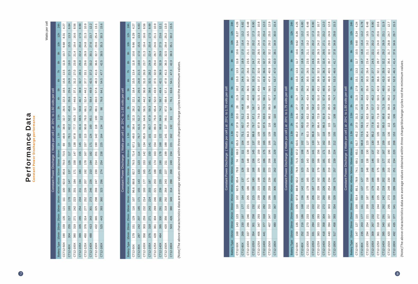
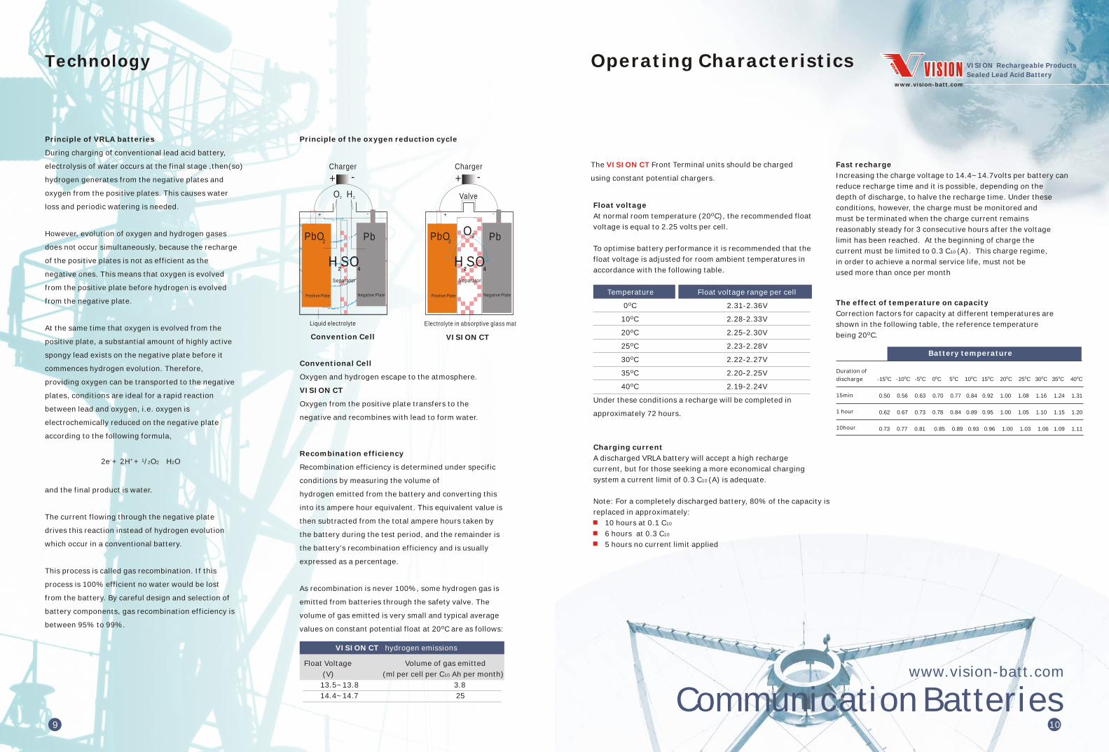
Communication Batterieswwwvision-battcom
9 10
Operating Characteristics
The Front Terminal units should be charged
using constant potential chargers
VISION CT
Float voltage
At normal room temperature (20 ) the recommended float
voltage is equal to 225 volts per cell
To optimise battery performance it is recommended that the
float voltage is adjusted for room ambient temperatures in
accordance with the following table
oC
Temperature Float voltage range per cell
0 231-236V
10 228-233V
20 225-230V
25 223-228V
30 222-227V
35 220-225V
40 219-224V
Under these conditions a recharge will be completed in
approximately 72 hours
oC
oC
oC
oC
oC
oC
oC
Charging current
A discharged VRLA battery will accept a high recharge
current but for those seeking a more economical charging
system a current limit of 03 C10 (A) is adequate
Note For a completely discharged battery 80 of the capacity is
replaced in approximately
10 hours at 01 C10
6 hours at 03 C10
5 hours no current limit applied
Fast recharge
Increasing the charge voltage to 144~147volts per battery can
reduce recharge time and it is possible depending on the
depth of discharge to halve the recharge time Under these
conditions however the charge must be monitored and
must be terminated when the charge current remains
reasonably steady for 3 consecutive hours after the voltage
limit has been reached At the beginning of charge the
current must be limited to 03 C10 (A) This charge regime
in order to achieve a normal service life must not be
used more than once per month
The effect of temperature on capacity
Correction factors for capacity at different temperatures are
shown in the following table the reference temperature
being 20
oC
Duration of
discharge
15min
1 hour
10hour
-15 -10 -5 0 5 10 15 20 25 30 35 40
050 056 063 070 077 084 092 100 108 116 124 131
062 067 073 078 084 089 095 100 105 110 115 120
073 077 081 085 089 093 096 100 103 106 109 111
o o o o o o o o o o o oC C C C C C C C C C C C
Battery temperature
wwwvision-battcom
VISION Rechargeable Products
Sealed Lead Acid Battery
Technology
Principle of the oxygen reduction cycle
PbO2
Positive Plate
Pb
Negative Plate
2
Separator
+ -
H SO2 4
+ -Charger
Valve
O
Electrolyte in absorptive glass mat
VISION CT
PbO2
Positive Plate
Pb
Negative Plate
Separator
+ -
H SO2 4
+ -Charger
2H
Liquid electrolyte
Convention Cell
2O
Principle of VRLA batteries
During charging of conventional lead acid battery
electrolysis of water occurs at the final stage then(so)
hydrogen generates from the negative plates and
oxygen from the positive plates This causes water
loss and periodic watering is needed
However evolution of oxygen and hydrogen gases
does not occur simultaneously because the recharge
of the positive plates is not as efficient as the
negative ones This means that oxygen is evolved
from the positive plate before hydrogen is evolved
from the negative plate
At the same time that oxygen is evolved from the
positive plate a substantial amount of highly active
spongy lead exists on the negative plate before it
commences hydrogen evolution Therefore
providing oxygen can be transported to the negative
plates conditions are ideal for a rapid reaction
between lead and oxygen ie oxygen is
electrochemically reduced on the negative plate
according to the following formula
and the final product is water
The current flowing through the negative plate
drives this reaction instead of hydrogen evolution
which occur in a conventional battery
This process is called gas recombination If this
process is 100 efficient no water would be lost
from the battery By careful design and selection of
battery components gas recombination efficiency is
between 95 to 99
- + 12e + 2H + 2O2rarrH2O
Conventional Cell
Oxygen and hydrogen escape to the atmosphere
VISION CT
Oxygen from the positive plate transfers to the
negative and recombines with lead to form water
Recombination efficiency
Recombination efficiency is determined under specific
conditions by measuring the volume of
hydrogen emitted from the battery and converting this
into its ampere hour equivalent This equivalent value is
then subtracted from the total ampere hours taken by
the battery during the test period and the remainder is
the batterys recombination efficiency and is usually
expressed as a percentage
As recombination is never 100 some hydrogen gas is
emitted from batteries through the safety valve The
volume of gas emitted is very small and typical average
values on constant potential float at 20 are as followsoC
VISION CT hydrogen emissions
Float Voltage Volume of gas emitted
(V) (ml per cell per C10 Ah per month)
135~138 38
144~147 25
Operating Instructions and Guidelines Installation and Commissioning Charge wwwvision-battcom
VISION Rechargeable Products
Sealed Lead Acid Battery
Accidental deep discharge
eg Discharge at a lower current for a longer time than
the original system specification
Failure of the charging system
Battery not recharged immediately after a discharge
When a battery is completely discharged
The utilisation of the sulphuric acid in the electrolyte is
total and the electrolyte now consists only of water
During recharge this condition may produce metallic
dendrites which can penetrate the separator and cause
a short circuit in a cell
The sulphation of the plate is at its maximum and the
internal resistance of the cell is also at its maximum
The battery should be recharged under a constant potential
of 228 volts per cell with the current limited to a maximum
of 03 C10(A) in order to prevent excessive internal heating
For instance for a CT12-155X the maximum charge current
is 465 amps If the sulphation of the cellbattery is extensive
then the recharge of the battery may require more than 96
hours
Note Deep discharging will produce a premature deterioration of the
battery and a noticeable reduction in the life expectancy of the
battery
For optimum operation the minimum voltage of the system
should be related to the duty as follows
t lt1h 165V
1 h ltt lt5h 170V
5 h ltt lt8h 175V
8 h ltt lt20h 180V
In order to protect the battery it is advisable to have system
monitoring and low voltage cut-out
Float charge ripple
Excessive ripple on the DC supply across a battery has the
effect of reducing life and performance
It is recommended therefore that voltage regulation across
the system including the load but without the battery
connected under steady state conditions shall be better
than 1 between 5 and 100 load
(I)
(II)
(III)
(I)
(II)
Duty Minimum end voltage
Transient and other ripple type excursions can be
accommodated provided that with the battery disconnected
but the load connected the system peak to peak voltage
including the regulation limits falls within 25 of the
recommended float voltage of the battery
Under no circumstances should the current flowing through
the battery when it is operating under float conditions
reverse into the discharge mode
Electro-Magnetic Compatibility (EMC)
products are covered by the EMC statement in
prEN 502261995 which reads as follows
Rechargeable cells or batteries are not sensitive to normal
electromagnetic disturbances and therefore no immunity
tests shall be required Free-standing rechargeable cells or
batteries electrically isolated from any associated electrical
system are for all practical purposes electromagnetically
inert and therefore the requirements for electromagnetic
compatibility shall be deemed to be satisfied
Note It should be noted that rechargeable cells or batteries are part
of an electrical system and the manner in which they are used could
invoke the requirements of the electromagnetic compatibility upon
that system In such cases the requirements of electromagnetic
compatibility shall be accommodated by the design of the system
Maintenance
Every month check that the total voltage at the battery
terminals is (N x 225V) for a temperature of 20
N = the number of cells in the battery and
225V = 20 float voltage
Once a year take a reading of the individual bloc voltages
in the battery A variation of 25 on individual voltages
from the average voltage is acceptable
The system must be checked once or twice a year
Principal factors affecting the life of recombination
batteries
Deep discharge
Poor control of the float voltage
Cycling or micro-cycling
Poor quality of charging current (excessive ripple)
High ambient temperature
VISION CT
oC
oC
11
Warning
Front Terminal units are already charged when
delivered
They should be unpacked with care Avoid short circuiting
terminals of opposite polarity as these units are capable of
discharging at a very high current especially if the lid or the
container is damaged
Acid leakage and unusual appearance must be avoided before
switching on noting open circuit voltage
There must be appointed man operating for 24 hs after
switching on to solving potential problems in time
noting voltage and current
Unpacking
It is advisable to unpack all the monoblocs and accessories
before commencing to erect and not to unpack and erect
monobloc by monobloc
All items should be carefully checked against the
accompanying advice notes to ascertain if any are missing
Advise the Sales Department of any discrepancies
A rigid plastic insulating cover is provided which totally
protects the unit terminals This is factory fitted to all
products of the range and there is no need to remove it
until access to the terminals is required
Setting up the battery stands
The structure should be assembled in accordance with
instructions supplied with the equipment
To level the stand use the adjustable insulating feet
Mounting in a cabinet
Ensure that the cabinet
Is sufficiently strong to cope with the weight of the
battery
Is suitably insulated
Is naturally ventilated
Connecting the monoblocs
Torque setting
Tighten the nuts or bolts to the recommended levels of
torque indicated on the product label
VISION CT Always use insulated tools for fitting and torquring up
battery connections
In series
The number of cells in series (N) will not affect the
selected float voltage per cell
Therefore charging float voltage = N x Cell float Voltage
No special circuit arrangements are required
In parallel
Using constant voltage chargers and ensuring that the
connections made between the charger and the batteries
have the same electrical resistance no special
arrangements have to be made for batteries in parallel
Although no special circuit arrangements are required
where the parallel connection is made at the charger or
distribution board to avoid out of step conditions
the bus bar run length and the area of cross section
should be designed so that the circuit resistance value
for each string is equal within limits 5
There is no technical reason for limiting the number of
strings but for practical installation reasons It is
recommended not allowed to exceed 3 strings in parallel
especially if the battery is used in high discharge rates
(backup time less than 15 mins)
General recommendations
Do not wear clothing of synthetic material to avoid static
generation
Use only a clean soft damp cloth for cleaning the
monoblocs Do not use chemicals or detergents
Use insulated tools
Commence installation at the least accessible point
Consult the drawing for the correct position of the
monobloc poles
Commissioning charge
Ensure that the batteries will be operated in a clean
environment
Before use the batteries should be charged at a constant
float voltage adjusted according to the ambient temperature
eg 135~138Vbattery at 20 for 48 to 96 hours or
alternatively a voltage of 144~147Vbattery at 20 can be
used to reduce the commissioning period from 24 to 15 hours
Where the batteries have been stored under harsh
conditions this increased voltage recharge is particularly
effective
oCoC
12
13
The VISION Front Terminal batterys compact
design and standard footprint suitable for 19rdquo
23rdquo and ETSI racking give users the benefit of
increased energy density
With all electrical connections at the front
installation and inspection are simpler and
quicker
Recharge of stored batteries
A refreshing charge shall be performed after this time at
135-138V battery at 20 for 48 to 96 hours
A current limit is not essential but for optimum charge
efficiency the current output of the charger can be limited
to 20 of the 10-hour rated capacity
The necessity of a refreshing charge can also be determined
by measuring the open circuit voltage of a stored battery
Refreshing charge is advised if the voltage drops below
210 volts per cell
Failure to observe these conditions may result in greatly
reduced capacity and service life
oC
Storage conditions
Store the battery in a dry clean and preferably cool location
Storage time
As the batteries are supplied charged storage time is limited
In order to easily charge the batteries after prolonged
storage it is advisable not to store batteries for more than
6 months at 20
3 months at 30
6 weeks at 40
Battery state of charge
The battery state of charge can be determined by measuring
the open-circuit voltage of cells in rest position for 24 hours
at 20
100 214Vpc
80 210Vpc
60 207Vpc
40 204Vpc
20 200Vpc
Open circuit voltage variation with temperature is 25mV
per 10
oC
oC
oC
oC
oC
State of charge Voltage
Battery AccommodationBattery Storage
wwwvision-battcom
VISION Rechargeable Products
Sealed Lead Acid Battery
14
Communication Batterieswwwvision-battcom