references and bibliography - link.springer.com978-1-84628-285-0/1.pdf · calladine, c.r....
TRANSCRIPT

Abdel-Rahman, T.M. and Shawki, G.S.A. (1989) Model-aided techniquesfor creative mechatronics designs. In Proceedings–Frontiers in EducationConference, pp.222–228.Aczel, A.D. (1996) Fermat’s Last Theorem: Unlocking the Secret of an AncientMathematical Problem. Viking.Adams, J.L. (1974) Conceptual Blockbusting. San Francisco: Freeman.Adhesives: Handbook of adhesive technology. Pizzi, A. and Mittal, K.L.eds.(c.1994) New York: Dekker.Adhesives: Structural adhesives directory and databook. (1996), 1st ed. London:Chapman & Hall. Adhesives: Wood Adhesives. (1995) Forest Products Society, Madison, WI:Forest Products Society Press.Agrawal, R., Kinzel, G.L., Srinivasan, R. and Ishii, K. (1993) Engineeringconstraint management based on an occurrence matrix approach. Journal ofMechanical Design, Transactions of the ASME 115(1):103–109.Akao, Y., Ed. (1990). Quality Function Deployment. Cambridge MA:Productivity Press. Akao, Y. and Mizuno S. (1994) QFD: The customer-driven approach to qualityplanning and deployment. Asian Productivity Organization.Alexander, C. (1964) Notes on the Synthesis of Form. Cambridge, MA:Harvard University Press.Alexander, C. and Manheim, M.L.(1965) The design of highway inter-changes: An example of a general method for analyzing engineering designproblems. Highway Research Record (83):48–87.Alexander, K.C. (1991) Artmaking: Bridge to metaphorical thinking. Arts inPsychotherapy 18(2):105–111.Allison, J.E. and Cole, G.S. (1993) Metal-matrix composites in the automo-tive industry: Opportunities and challenges. JOM 45(1):19–24 (Jan.).Ambrose, S.A. and Amon, C. H. (1997) Systematic design of a first-yearmechanical engineering course at Carnegie Mellon University. Journal ofEngineering Education 86(2):173–181 (April).Amirkhan, J.H. (1994) Criterion validity of a coping measure. Journal ofPersonality Assessment 62(2):242-261 (April).Appleby A.J., Ed. (1987) Fuel cells: trends in research and applications.Washington: Hemisphere. Appleby, A.J. and Foulkes, F.R. (1993) Fuel Cell Handbook. Malabar, FL:Krieger.
229
REFERENCES AND BIBLIOGRAPHY

Arce-Villalobos, O.A. (1993) Fundamentals of the Design of Bamboo Structures.Eindhoven: Technische Universiteit.Atkins, PW. (2003) Galileo's Finger: The Ten Great Ideas of Science, New York:Oxford University Press.Bailey, R.L. (1980) Solar-Electrics Research and Development, Ann Arbor, MI:Ann Arbor Science.Balmer, A.J., Cotter, C.E. and Harnish, M.(1998) Mousetrap Powered Carsand Boats. Round Rock, TX: Doc Fizzix.Belloc, H. (2002) Cautionary Tales for Children (with illustrations by EdwardGorey), Orlando, FL: Harcourt.Besenhard, J.O., Ed. (1999) Handbook of Battery Materials. New York: Wiley-VCH.Biden, E. and Rogers, R. (2002) A tradeshow for products developed in sec-ond year mechanical engineering. In Proceedings–Frontiers in EducationConference, (2):F2D/23-F2D/26. Bisantz, A.M., Roth, E., Brickman, B., Gosbee, L.L., Hettinger, L. andMcKinney, J. (2003) Integrating cognitive analyses in a large-scale systemdesign process. International Journal of Human Computer Studies58(2):177–206.Blackowiak, A.D., Rand, R.H. and Kaplan, H. (1997) The dynamics of theCelt with second-order averaging and computer algebra. Proceedings ofASME Design Engineering Technical Conference, September 14–17,Sacramento, CA, Paper DETC97/VIB–4103.Boden, M. (1979) Jean Piaget. London: Penguin.Brown, J.R. (1991) Laboratory of the Mind: Thought Experiments in theNatural Sciences. London: Routledge.Brown, J.R. (2002) Thought Experiments, In The Stanford Encyclopedia ofPhilosophy (http://plato.stanford.edu/), E.N. Zalta Ed.Bruning, R. and Horn, C. (2000) Developing motivation to write.Educational Psychologist, Special issue: Writing development: The role of cognitive,motivational, and social/contextual factors 35(1):25–37.Bullock, G.N., Denham, M.J., Parmee, I.C. and Wade, J.G. (1995)Developments in the use of the genetic algorithm in engineering design.Design Studies 16(4):507.Byo, J.L. (1993) The influence of textural and timbral factors on the abili-ty of music majors to detect performance errors. Journal of Research in MusicEducation 41(2):156–167.Calladine, C.R. (1978) Buckminster Fuller’s “tensegrity” structures andClerk Maxwell’s rules for the construction of stiff frames. InternationalJournal of Solids and Structures 14(2):161–172.
230Make-andTest Projects in Engineering Design

Calladine, C.R. (1983) Theory of Shell Structures. New York: CambridgeUniversity Press.Campbell, D. (2001) The long and winding (and frequently bumpy) roadto successful client engagement: One team’s journey. System DynamicsReview 17(3):195-215.Canter, L. (1977) Environmental Impact Assessment. New York: McGraw-Hill. Capp, A., Frazetta, F. and Kitchen, D. (1960-1961) Al Capp's Li'l Abner: TheFrazetta Years : Volume 4. Oakland CA: Darkhorse.Carson, D.K. and Runco, M.A. (1999) Creative problem solving and prob-lem finding in young adults: Interconnections with stress, hassles, and cop-ing abilities. Journal of Creative Behavior 33(3):167–190.Chanute, O. (1897) Recent experiments in gliding flight. In James Means,Aeronautical Annual, Boston (3):37.Chen, S.-J. and Lin, L. (2002) A project task coordination model for teamorganization in concurrent engineering. Concurrent Engineering Research andApplications 10(3):187–202.Chen, X. and Hoffmann, C.M. (1995) On editability of feature-baseddesign. Computer Aided Design 27(12):905–914.Christiansen, A.W. and Conner, A.H. (1996) Wood Adhesives. Proceedingsof a symposium sponsored by the USDA Forest Service, Forest ProductsLaboratory, June 29–30, 1995, Portland, OR. Madison, WI: Forest ProductsSociety.Clancey, W.J. (1997) Situated Cognition: On Human Knowledge and ComputerRepresentation. New York: Cambridge University Press.Cohen, L. (1996) Quality Function Deployment: How to Make QFD Work forYou, Reading, MA: Addison-Wesley, (Reviewed in the Journal of ProductInnovation Management, March 1996:183-184).Composites Bonding – see Damico et al.Connor-Greene, P.A. (2002) Problem-based service learning: The evolu-tion of a team project. Teaching of Psychology 29(3):193–197.Cooper, P.W. and Kurowski, S.R. (1996) Introduction to the Technology ofExplosives. New York: VCH.Cottrell, D.S. and Ressler, S.J. (1997) Integrating design projects into anintroductory course in mechanics of materials. ASEE Annual ConferenceProceedings.Courant, R. and Robbins, H. (1996) What is Mathematics?; 2nd. Edition,Revised by Stewart, I. New York: Oxford University Press.Cox, M.V. and Rowlands, A. (2000) The effect of three different educa-tional approaches on children’s drawing ability: Steiner, Montessori andtraditional. British Journal of Educational Psychology 70(4):485–503.
231References and Bibliography

Coxeter, H.S.M. (1973) Regular Polytopes, New York: Dover.Crick, F. and Watson, J. (1953) A structure for deoxyribose nucleic acid.Nature (171):737.Crompton, T.R. (2000) Battery Reference Book. Oxford: Newnes. Crouch, T. (1981) A Dream of Wings: Americans and the Airplane, 1875–1905.New York: W.W. Norton.Daetz, D., Barnard, W. and Norman, R. (1995) Customer Integration: TheQuality Function Deployment (QFD) Leader’s Guide for Decision Making. NewYork: Wiley.Damico, D.J. Wilkins T.L., Jr., and Niks, S.L.F., Eds. (1994) CompositesBonding. Philadelphia: ASTM.Davidson, J. K. and Hunt, K. H. (2004) Robots and Screw Theory. New York:Oxford University Press.de Bono, E. (1985) Six Thinking Hats. Boston: Little, Brown, and Co.de Bono, E. (1978) Teaching Thinking. Harmondswort: Penguin.de Bono, E. (1970) Lateral thinking: Creativity step by step. New York: Harper& Row. Dell, R.M. and Rand, D.A.J. (2001) Understanding Batteries. Cambridge:Royal Society of Chemistry.De Mille, R. (1994) Put Your Mother on the Ceiling. New York: Viking.De Paul, G. and Mercer, J. (1956) Li’l Abner: The Musical.Design Matrix: http://www.designmatrix.com/tools/cluster_tools.html.Designing Plastic Parts for Assembly – see Tres.De Simone, D.V. (1968) Education for Innovation. Oxford: Pergamon. Dogan, K. and Goetschalckx, M. (1999) Primal decomposition method forthe integrated design of multi-period production-distribution systems. IIETransactions (Institute of Industrial Engineers) 31(11):1027–1036.Dowie, M. (1977) Pinto madness, Mother Jones p.35 (September/October).Du, H. and Nair, S.S. (1996) Design of a train separator for hydraulic cap-sule pipeline control. ASME Fluid Power Systems and Technology 3:65–70.Duckworth, E., See Piaget.Durfee, W.K. (1994) Engineering education gets real. Technology Review97(2): 42–51 (Feb.–Mar.).Dutta, R.D. (1991) A model of change in organizational health to improvequality of life. Social Science International, 7(2):6–11 (July).D’Zurilla, T. and Chang, E.C. (1995) The relations between social problemsolving and coping. Cognitive Therapy & Research 19(5):547–562 (Oct.).Eddy, P., Potter, E. and Page, B. (1976) Destination Disaster. London: Hart-Davies, McGibbon.
232Make-andTest Projects in Engineering Design

Edison, T. (1932) An interview reported in Harper’s Monthly Magazine,September.Egelhoff, C.J. and Odom, E.M. (1999) Machine design: Where the actionshould be. In Proceedings - Frontiers in Education Conference (2): 12c5:13–18.Einstein, A. and Infeld, L. (1938) Evolution of Physics. New York: Simon &Schuster.Epstein, H.T.(1970) A Strategy for Education. New York: Oxford UniversityPress.Falk, G. (1982) An empirical study measuring conflict in problem-solvinggroups which are assigned different decision rules. Human Relations35(12):1123–1138.Field, B.W., Weir, J.G. and Burvill, C.R. (2003) Some misconceptions instudent's understanding and use of physics for solving problems in engi-neering mechanics. University of Melbourne Design Report DR0203,University of Melbourne: Desktop Design Centre.Fodor, E.M. and Carver, R.A. (2000) Achievement and power motives, per-formance feedback, and creativity. Journal of Research in Personality34(4):380–396 (Dec.).Fodor, E. M. and Roffe-Steinrotter, D. (1998) Rogerian leadership style andcreativity. Journal of Research in Personality 32(2):236–242 (June).French, M. (1988) Invention and Evolution: Design in Nature and Engineering.New York: Cambridge University Press.
French, M. (1985) Conceptual Design for Engineers. London: The DesignCouncil.Fuchs, H.O.(1976) Private communications at Stanford University.Fuchs, H.O. and Steidel, R.F., Jr. (1973) 10 Cases in Engineering Design.Essex, UK: Longman. Gedanken (German): thoughts, ideas; see also Brown, J. R.(2002); URL:<http://plato.stanford.edu/archives/sum2002/entries/thought-experiment/>.Gere, J.M. and Timoshenko, S.P. (2002) Mechanics of Materials. London:Chapman & Hall.Gibbs-Smith, C. and Reese, G. (1978) The Inventions of Leonardo Da Vinci.Oxford: Phaidon. Gladman, M. and Lancaster, S. (2003) A Review of the BehaviourAssessment System for Children. School Psychology International24(3):276–291 (Aug.).Glickauf-Hughes, C. and Campbell, L.F. (1991) Experiential supervision:Applied techniques for a case presentation approach. Psychotherapy: Theory,Research, Practice, Training 28(4):625–635Gordon, J.E. (1979) Structures or why things don’t fall through the floor.Harmondsworth: Penguin.
233References and Bibliography

Green, D.W., Winandy, J.E. and Kretschmann, D.E. (1999) Mechanicalproperties of wood. In Wood handbook: Wood as an engineering material.Forest Products Laboratory General Technical Report FPL; GTR-113:4.1–4.Madison, WI: USDA Forest Service. Gruber, H. and Voneche, J., Eds. (1977) The Essential Piaget. New York:Basic. Gryskiewicz, N.D. and Tullar, W.L. (1995) The relationship between per-sonality type and creativity style among managers. Journal of PsychologicalType (32):30–35.Güémez, J., Valiente, R., Fiolhais, C. and Fiolhais, M. (2003) Experimentswith a sunbird. American Journal of Physics (71):1264. Guinta, L.R. and Praizler, N.C. (1993) The QFD Book: The Team Approachto Solving Problems and Satisfying Customers through Quality FunctionDeployment. New York: AMACOM; Reviewed in the Journal of ProductInnovation Management, June 1994:275–276.Handbook of Adhesive Technology – see Pizzi.Hart-Davies, A. (1999) The World’s Stupidest Inventions. Reading: Cox andWyman.
Härtel, H. (1994) COLOS: Conceptual learning of science. In de Jong, T.and Sarti, L., Eds. Design and Production of Multimedia and Simulation-basedLearning. Norwell, MA: Kluwer pp. 189–217.Hauser, J.R. and Clausing, D. (1988) The house of quality. Harvard BusinessReview 66(3):67–73.Hawking, S. W. (1988) A Brief History of Time. New York: Bantam.Henry, J. (1991) Creative Management. London: Sage.Herring, A.M. (1897) Recent advances toward a solution of the problem ofthe century. Aeronautical Annual (3):70–74.Hewitt, G.F. (2000) Introduction to Nuclear Power. New York: Taylor &Francis.Hibbard, W.J. and Hibbard, R.L. (1995) Generating excitement aboutmechanical engineering by using hands-on projects. In ASEE AnnualConference Proceedings (2, Investing in the Future) pp.2471–2476.Hodge, B.K. and Taylor. R.P. (1999) Analysis and Design of Energy Systems.Upper Saddle River, NJ: Prentice Hall.Janssen J.J.A. (1995) Building with Bamboo – A Handbook. London:Intermediate Technology.Jewkes, J., Sawers, D. and Stillerman, R. (1969) The Sources of Invention.New York: W.W. Norton.Johnson, P.R. (1955) Leaning Tower of Lire. American Journal of Physics23:240.
234Make-andTest Projects in Engineering Design

Johnston, W.D., Jr. (1980) Solar Voltaic Cells. New York: Dekker.Jones, J.B. and Dugan, R.E.(1996) Engineering Thermodynamics. EnglewoodCliffs, NJ: Prentice Hall. Jones, R.K. and Wang, E. (2001) Experiences with an engineering technol-ogy course for education majors. Frontiers in Education Conference1:T1E/4–T1E/8. (Oct. 10–13). Jung, C.G. and Hull, R.F.C., Trans. (1990) The basic writings of Carl GustavJung. Bollingen series, No. 20. Princeton, NJ: Princeton University Press.Kaisinger, R. (2002) Build a Better Mousetrap, Make Classic Inventions, DiscoverYour Problem Solving Genius and Take the Inventor’s Challenge. Hoboken, NJ:Wiley.Kalamaras, G.S. (1997) Computer-based system for supporting decisionsfor tunneling in rock under conditions of uncertainty. International Journal ofRock Mechanics and Mining Sciences 34(3–4):588.Kelly, F.C. (1996) Miracle at Kitty Hawk, The Letters of Wilbur and OrvilleWright. New York: Da Capo.King, R. (1995) Designing Products and Services That Customers Want.Cambridge MA: Productivity Press.Klein, J.P. (1975) Socratic dialogue vs. behavioural practice in the develop-ment of coping skills. Alberta Journal of Educational Research 21(4):255–261.Klenk, P., Barcus, K. and Ybarra, G.A. (2002) Techtronics: Hands-on explo-ration of technology in everyday life. In Proceedings – Frontiers in EducationConference (1):T3C/18-T3C/23. Kondratieff, N. (1984) The Long Wave Cycle. New York: Richardson andSnyder.Korfmacher, J. and Spicer, P. (2002) Toward an understanding of the child’sexperience in a Montessori Early Head Start program. Infant Mental HealthJournal, Special Issue: Early Head Start 23(1–2):197–212, (Feb.).Ledsome, C. (1987) Engineering Design Teaching Aids. London: The DesignCouncil.Lienhard, J.H., IV and Lienhard, J.H., V (2004) A Heat Transfer Text Book.Lexington MA: Phlogiston.Likert, D, and Likert, J. (1978) A method for coping with conflict in prob-lem-solving groups. Group & Organization Studies 3(4):427–434, (Dec.).Lillard, P.P. (1997) Montessori in the Classroom: A Teacher’s Account of HowChildren Really Learn. New York: Random House.Lillard, P,P. (1996) Montessori Today: A Comprehensive Approach to EducationFrom Birth to Adulthood. New York: Random House.Logan E., Ed. (1995) Handbook of Turbomachinery. New York: Dekker.Logan, E. (1993) Turbomachinery. New York: Dekker.Lotz, N.W. (1995) Trying to coincide the inner- and outer world: TheSocratic dialogue. Communication & Cognition 28(2-3):165–186.
235References and Bibliography

Love, L.J. and Dickerson, S.L. (1994) Mechanical systems lab: A real lifeapproach to teaching engineering. ASME, Dynamic Systems and ControlDivision, Publication DSC (55–2), Dynamic Systems and Control 2:1063–1066. McKim, R.H. (1978) The Imaginarium: An environment and program foropening the mind’s eye. In Visual Learning, Thinking andCommunication, B.S. Randhawa and W.C. Coffman, Eds. New York:Academic Press.McKim, R.H.(1972) Experiences in Visual Thinking. Monterey, CA: Brooks-Cole.Martinez-Pons, M. (2001)The Psychology of Teaching and Learning: A Three-step Approach. New York: Continuum.Mayhew, Y. and Hollingsworth, M.(1996) Engineering Thermodynamics: Workand Heat transfer Solutions Manual. Harlow: Longman. Mensch, G. (1975) Das Technogische Patt (Stalemate in Technology).Frankfurt-am Main:Umschau Verlag.Miranda, M.L. (2000) Developmentally appropriate practice in a YamahaMusic School. Journal of Research in Music Education 48(4):294–309.Mizuno, S. and Akao, Y., Eds. (1994) QFD: The Customer-Driven Approachto Quality Planning and Deployment. Cambridge MA: Productivity.Moje, E.B., Collazo, T., Carrillo, R. and Marx R.W. (2001) Maestro, whatis ‘quality’?: Language, literacy and discourse in project-based science.Journal of Research in Science Teaching 38(4):469–498 (April).Montessori, M. (1976) Education for Human Development: UnderstandingMontessori. New York: Schocken.Moore, J. (2005) Is higher education ready for transformative learning? – Aquestion explored in the study of sustainability. Journal of TransformativeEducation 3(1):76–91 (Jan.). Moran, M.J. and Shapiro, H.N. (2000) Fundamentals of EngineeringThermodynamics. New York: Wiley.Motro, R. (2003) TENSEGRITY: Structural Systems for the Future. London:Kogan Page.Murphy, P.S. (1994) The contribution of art therapy to the dissociative dis-orders. Art Therapy 11(1):43–47.Narri, Y. and Mummadi, V. (1999) Adaptive controller for PV suppliedbuck-boost converter. In Proceedings of the International Conference on PowerElectronics and Drive Systems 2:789–793.Newman, W.R. (2002) Gehennical Fire: The Lives of George Starkey, anAmerican Alchemist in the Scientific Revolution. Chikago: University of ChicagoPress.Ng, W.-Y. (1991) Interactive descriptive graphical approach to data analysisfor trade-off decisions in multi-objective programming. Information andDecision Technologies 17(2):133–149.
236Make-andTest Projects in Engineering Design

Niku, S.B. (1995) Metamorphic mechanical dissection and design in fresh-man engineering courses. In ASEE Annual Conference Proceedings, v. 2,Investing in the Future:2035–2038.Nolan, D.P. (1996) Handbook of Fire and Explosion Protection EngineeringPrinciples for Oil, Gas, Chemical, and Related Facilities. Westwood, NJ: Noyes. Nuclear Energy Agency (2003) Nuclear Energy Today. Paris: Nuclear EnergyAgency, Organisation for Economic Co-operation and Development.Ocean Energy: See also www.eere.energy.gov/RE/ocean.html.Ord-Hume, A.W.J.G.(1977) Perpetual motion: The history of an obsession. NewYork: St Martin’s.Otsuka, K. and Wayman, C. M., Eds. (1998) Shape Memory Materials.Cambridge, New York : Cambridge University Press.Pahl, G. and Beitz, W. (1996) Engineering Design: A Systematic Approach, 2nded. trans. Ken Wallace, Lucienne Blessing and Frank Bauert; ed. KenWallace. London: Springer. Papastavridis, J.G.(2002) Analytical Mechanics: A Comprehensive Treatise on theDynamics of Constrained Systems, For Engineers, Physicists, and Mathematicians.New York: Oxford University Press.Park, R. (2000) Voodoo Science: The Road from Foolishness to Fraud. New York:Oxford University Press.Parmee, I.C. (1997) Evolutionary computing for conceptual and detaileddesign. In Quagliarella et al., Eds. (1999) Genetic Algorithms and ComputerScience. New York: Wiley, pp.133–152.Parrott, C.A. and Strongman, K.T. (1985) Utilization of visual imagery increative performance. Journal of Mental Imagery 9(1):53–66.Perry, N.E., VandeKamp, K.O., Mercer, L.K. and Nordby, C.J. (2002 )Investigating teacher-student interactions that foster self-regulated learn-ing. Educational Psychologist 37(1):5–15 (Mar.).Piaget, J. (1970) Genetic Epistemology. trans. E. Duckworth, New York:Norton.Pizzi, A. and Mittal, K.L., Eds. (2003) Handbook of Adhesive Technology. NewYork: Dekker.Plato and Guthrie W.K.C. (1956) Protagoras and Meno. Harmondsworth:Penguin.Pocius, A.V. (2002) Adhesion and Adhesives Technology: An Introduction.Munich: Hanser.Popper, K. (1963) Conjectures and refutations: The growth of scientific knowledge.New York Routledge. Radjou, N., Cameron, R., Kinikin, E. and Herbert, L.(2004) InnovationNetworks, A New Market Structure Will Revitalize Invention-To-InnovationCycles. Boston: Forrester Research.
237References and Bibliography

Reiner-Decher, R. (1994) Energy Conversion: Systems, Flow Physics, andEngineering. New York: Oxford University Press.Reiter-Palmon, R., Mumford, M.D., O’Connor, B.J. and Runco, M.A.(1997 )Problem construction and creativity: The role of ability, cue consis-tency and active processing. Creativity Research Journal 10(1):9–23.Rittel, H. (1987) Keynote address. In International Conference on EngineeringDesign, Boston: ASME .Ross, M.E., Salisbury-Glennon, J.D., Guarino, A., Reed, C.J. and Marshall,M. (2003) Situated Self-regulation: Modeling the interrelationships amonginstruction, assessment, learning strategies and academic performance.Educational Research & Evaluation 9(2):189–209 (June).Samuel, A.E. (1986) Student centered teaching in engineering design.Instructional Science 15:47–79.Samuel A.E. (1984) Educational objectives in engineering design.Instructional Science 13: 243–273.Samuel, A.E. and Lewis W.P. (1986) A Socratic approach to design teaching.In Proceedings National Conference on Teaching Designers for 21st. Century.University of NSW, pp.143–151 (Feb.).Samuel, A.E. and Lewis, W.P. (1974) Student response to an open-endeddesign project. I.E. Aust. Mech. Engineering Transactions MC-10(1):23–27.Samuel, A.E. and Weir, J.G. (1999) Introduction to Enginering Design:Modelling, Synthesis and Problem Solving Strategies. London: ElsevierButterworth.Samuel, A.E. and Weir, J.G. (1995) Concept learning in engineering designusing cognitive maps. International Conference on Engineering Design, ICED95, Prague, August, 22–24: pp.303–311.Samuel, A.E., Lewis, W.P. and Weir, J.G. (2000) A common language of design for excellence. In Proceedings Engineering Design Conference 2000,Brunel, Uxbridge, July, pp.439–448.Samuels, M. and Samuels, N. (1975) Seeing with the Mind’s Eye, The History,Techniques and Uses of Visualisation. New York: Random House.Seabrook, W. (1941) Dr. Wood: Modern wizard of the laboratory. Orlando, FL:Harcourt.
Seffen, K.A. (2001) On the behaviour of folded tape-springs. Journal ofApplied Mechanics, Trans. ASME (68):369–375.Setlow, R.B. and Pollard, E.C. (1962) Molecular Biophysics. Reading, MA:Addison Wesley.Shute, N. (1951) No Highway. New York: Morrow.Simon, H.A. (1996) The Sciences of the Artificial. 3rd ed. Cambridge, MA:The MIT press.
238Make-andTest Projects in Engineering Design

Simon, H.A. (1978) Rational decision-making in business organizations.Nobel Memorial Lecture, 8 December 1978.Simon, H.A. (1952) A Behavioral model of rational choice. Quarterly Journalof Economics 69:99–118.Simon, H. A. and Kaplan, C.A. (1989) Foundations of cognitive science. InPosner, M.I., Ed. Foundations of Cognitive Science, Cambridge MA: MITPress.Smith, D.K. and Alexander, R.C. (1988) Fumbling the Future: How XeroxInvented, Then Ignored, The First Personal Computer. New York: Morrow.Snelson, K.D. (2002) Space Frame Structure Made by 3-D Weaving of RodMembers. US Patent 2002/0,081,936.
Snelson, K.D. (1973) Tensegrity Masts. Bolinas, CA: Shelter.Sobel, D. (2000) Galileo’s Daughter. London: Fourth Estate.Sobel, D. (1995) Longitude. Harmodsworth: Penguin.Sodan, A.C. (1999) Toward successful personal work and relations:Applying a yin/yang model for classification and synthesis. Social Behaviorand Personality 27(1):39–71.Srinivasan, A.V. and McFarland, D.M. (2000) Smart Structures: Analysis andDesign. Cambridge: Cambridge University Press.Terninko, J., Ed. (1997) Step by Step QFD: Customer Driven Product Design.Boca Raton, FL: CRC.Terzis, G. (2001) How crosstalk creates vision-related eureka moments.Philosophical Psychology 14(4):391–421 (Dec.).Timoshenko, S.P. (1981) Strength of materials. Volume 1, Melbourne, FL:Krieger.
Timoshenko, S.P. (1953) History of strength of materials. New York: McGraw-Hill.Tres, P.A. (2003) Designing Plastic Parts for Assembly. 5th ed. Munich:HanserGardner.Vaughn, M. and Stairs, A. (2000) Delicate balance: The praxis of empower-ment at a midwestern Montessori school. In National CommunicationAssociation Conference, Seattle, WA.Vesper, K.H. (1975) Engineers at work: A Casebook. Boston:HoughtonMifflin.Vidal, F. (1994) Piaget Before Piaget. Cambridge MA: Harvard UniversityPress.Walker, J. (1979) The Amateur Scientist, Scientific American 241:172–184.
Weber, R.L. (1973) A Random Walk in Science. London: The Institute ofPhysics. p.77., N-Rays, based on Seabrook (1941).
239References and Bibliography

Weilerstein, P.J. (1999) Fostering applied innovation in higher education:The National Collegiate Inventors and Innovators Alliance. Frontiers inEducation Conference 1:11a6-1–11a6-3.Wentzel, K.R and Watkins, D.E. (2002) Peer relationships and collaborativelearning as contexts for academic enablers. School Psychology Review31(3):366-377.Werner, J.M and Lester, S.W. (2001) Applying a team effectiveness frame-work to the performance of student case teams. Human Resource DevelopmentQuarterly 12(4):385-402.Wesenberg, P. (1994) Bridging the individual-social divide: A new perspec-tive for understanding and stimulating creativity in organizations. Journal ofCreative Behavior 28(3):177–192.White, B. (1983) Sources of difficulty in understanding Newtonian dynam-ics. Cognitive Science 7(1):41–65A.White, B.Y. and Frederiksen, J.R. (1998) Inquiry, modeling, and metacog-nition: Making science accessible to all students. Cognition and Instruction16(1):3–118.Wiles, A. (1995) Modular elliptic curves and Fermat’s Last Theorem. Annalsof Mathematics 142:443–551.Williams, R. (2002) Retooling: A historian confronts technological change.Cambridge: The MIT Press. Winchester, S. (1999) The surgeon of Crowthorne. London: Penguin.Wohl, B. (1979) The China Syndrome. New York: Bantam Press.
Wood Adhesives (1996)– see Christiansen and Conner.
Wood handbook—Wood as an engineering material. Forest Products Laboratory.1999. Gen. Tech. Rep. FPL-GTR-113. Madison, WI: U.S. Department ofAgriculture, Forest Service, Forest Products Laboratory.Xanthanite Explosives (1999) Performance Parameters of Condensed HighExplosives, Enfield, S.A.: Xanthanite Explosives Publications.Yamaha music : www.yamaha-music.com.sg/main_aboutus.html.Yoji, A., Ed. (1990) Quality Function Deployment: Integrating CustomerRequirements into Product Design. Cambridge, MA: Productivity Press.Zeigler, T.R. (1987) Portable Shelter Assemblies. US Patent 4,689,932. Zeigler, T.R. (1997) Family of Collapsible Structures & a Method of Making aFamily of Collapsible Structures. US Patent 5,651,22.Zucker, R.D. and Biblarz, O. (2002) Fundamentals of Gas Dynamics.Hoboken, NJ: Wiley.
240Make-andTest Projects in Engineering Design

Engineering Case LibraryBrewerton, F.J.(1970) The engineering case study–An interdisciplinarycomparison. SAE Paper 70003.Buck, D. and Stucki, D.J. (2001) JKarelRobot: a case study in supportinglevels of cognitive development in the computer science curriculum. InProceedings of the thirty second SIGCSE technical symposium on Computer ScienceEducation pp.16–20.Delatte, N.J., Jr. (1997) Failure case studies and ethics in engineeringmechanics courses. Journal of Professional Issues in Engineering Education andPractice 123(3):111–116.Dunn-Rankin, D., Bobrow, J.E., Mease, K.D. and McCarthy, J.M. (1998)Engineering design in industry:Teaching students and faculty to apply engi-neering science in design, Journal of Engineering Education 87(3):219–222.Ellis, C.D., Rakowski, R.T. and Marsh, P.T.C. (1985) Design project casestudy: Capacitor design for high temperature applications. InternationalJournal of Applied Engineering Education 1(5):349–353.Feldy, E.C., Ed. (2003) Mechanical engineering design education-2001:Issues and case studies. ASME Design Engineering Division (113):183 pp.Henderson, J.M. and Steidel, R.F., Jr. (1974) Engineering case studies —The academic/professional link. IEE Conference Publication 11:342–346.Hirsch, R.A. (1974) The case method as a means of achieving industry-uni-versity interaction in design education. ASME Paper 74-WA/DE-27.Kardos, G.(1992) Getting the most from make-and-break projects.Innovation, Teaching and Management 205.Kardos, G. (1974) Engineering cases—Feedback from industry. ASMEPaper 74-WA/DE-31.Kardos, G. and Smith, C.O. (1983) Engineering cases as tools for teachingdesign. Mechanical Engineering 105(3):68–71.Lichy, W.H. and Mariotti, J.J. (1970) The use of case methods at GeneralMotors Institute. SAE Preprint 70005.McKechnie, R.E. (1975) The engineering case study as an aid to careeradvancement. ASME Paper 75-DE-19.McNair, M.P. (1954) The Case Method At The Harvard Business School. NewYork:McGraw-Hill.Midha, A., Turcic, D.A. and Bosnik, J.R.(1981) Creativity in the classroom– a collection of case studies in linkage synthesis. Mechanism & MachineTheory 19(1):25–44.Newstetter, W. C. (1998) Of green monkeys and failed affordances: A casestudy of a mechanical engineering design course. Research in EngineeringDesign – Theory, Applications, and Concurrent Engineering 10(2):118–128.
241References and Bibliography

Noymer, P.D., Hazen, M.U. and Yao, S.C. (1998) Integrated thermal sci-ence course for third-year mechanical engineering students. ASME HeatTransfer Division 361-3:49–53.Samuel, A.E. and Lewis, W.P. (1987) Teaching less and learning more – aSocratic approach to engineering design education. ASME Transactions1055–1065.Seif, M.A. (1997) Design case studies: A practical approach for teachingmachine design. Frontiers in Education Conference 3:1579–1582.Smith, C.O. and Kardos, G. (1987) Processes for teaching design process-es. ASME transactions 1081–1088.Vesper K. H. and Adams J.L. (1971) Teaching objectives, style, and effectwith the Case Method. Engineering Education 61(7):831–833
Readings for MaT Project PlanningAaseng, N. (2000) Construction: Building the impossible. Minneapolis: Oliver.
Anderson, N. (1983) Ferris Wheels. New York: Pantheon.
Balmer, A.J. (1998) Mousetrap Cars:The Secrets to Success. Round Rock, TX:Doc Fizzix.
Bochinski, J.B.(2004) The Complete Workbook for Science Fair Projects. NewYork:Wiley.
Bochinski, J.B.(1996) The Complete Handbook of Science Fair Projects.Hoboken, NJ: Wiley.
Bransford, B.D. and Stein, B.S. (1984) The IDEAL Problem Solver. NewYork: W. H. Freeman.
Duffy, T. (2000) The Clock. New York: Atheneum.
French, M. (1992) Form, Structure and Mechanism. New York: McMillan.
242Make-andTest Projects in Engineering Design

Mechanics is the science of forces acting on bodies at rest and on bodies in motion.The whole of mechanics is subdivided into statics, kinematics and dynamics. • Statics deals with forces on bodies at rest and in general addresses the equi-
librium of these forces by both external and internal reactions.
• Kinematics is the study of the relative motion of one or more connected or dis-connected bodies or particles, without any reference to forces acting on them.
• Dynamics is the study of forces acting on bodies in motion.
A1.1 STATICS
A1.1.1 FORCESAs a helpful introduction to this aspect of mechanics we examine the types of forcesand combinations of forces that can act on bodies or systems of bodies. We oftentalk about forces, but we equally often overlook the fact that a force is not an eas-ily measured quantity. In fact in a most general way the concept (idea) of a force isbased entirely on the “effect” it can create.
When we weigh ourselves on a simple bathroom scale, the effect created by ourmass acted on by gravity is to displace a spring inside the scale. A pointer attachedto the spring will then indicate the “force” of gravity acting on our body mass.
243
APPENDIX A1A PRIMER ON MECHANICS
When we were carrying on our wind-tunnel work we had no thought ofever trying to build a power aeroplane. We did that work just for the funwe got out of learning new truths. Orville Wright, 1928 (in Kelly, 1996)
In the early twentieth century Albert Einstein revolutionised theoreticalphysics by overturning Newton's view of gravity. With it went Newton'sview of the universe as permanent and unchanging. Although Einsteinhimself resisted it, the equations seemed to predict a dynamic universe. Stephen Hawking, 1999
Figure A1. Schematic view of weightlifter action Figure A2. Weightlifter in action

Similarly, when a weightlifter lifts a weight (refer to Figures A1 and A2), his mus-cles and bones react to the force of gravity acting on the mass of the weight beinglifted. Isaac Newton recognised that two masses attract each other in proportion totheir masses and inversely proportional to the square of the distance between theirrespective centres. The constant of proportionality in this relation is the “gravitation-al constant” G.Acceleration due to gravity g = (G x M)/r2, where
G = the gravitational constant = 6.673 x 10⁻¹¹ m3 kg-1 s-2
M = mass of the earth = 5.974 x 1024 kg
R = the radius of the earth = 6,378,140 m at the equator.The earth is a flattened sphere (referred to by geometers as a “prolate spheroid”)
and its radius at the poles is about 2100 m less than at the equator. The current holder of the world super-heavy class (greater than 105 kg body
weight) championship for “clean and jerk”A1 is Hossein Reza Zadeh of Iran, who lift-ed 263.5 kg at the Athens Olympics in 2004. The clean and jerk lifting style is shownin the photo of Figure A2. It is instructive to calculate the relative effect on a recordsuch as Reza Zadeh's if the weightlifting competition were held at Quito (capital cityof Ecuador, through which the equator passes) and at Svalbard, on the Arctic islandof Spitsbergen (at 78 degrees of latitude).
Forces can act as individuals or in pairs forming couples. A force is a vector quan-tity having magnitude, direction and sense and it is usually depicted as a directedarrow. They can act in a plane (called planar system of forces) and in three dimen-sions (called a “general system of forces”).
A pure couple is a planar system of two equal and opposite forces separated bysome distance. The effect of a couple is called a moment and the moment of a cou-ple is measured by the product of the force and the distance between them.Moments are also vector quantities and may be represented by a directed arrow nor-mal to the plane in which the couple acts.
Figure A3 shows a planar system of forces acting on a mathematically thin planarbody called a “lamina”. The forces are shown acting normal to the lamina at their
244Make-and-Test Projects in Engineering Design
A1 Clean and jerk is a two stage-lifting technique used in weightlifting, with each lifting stage raising the barabout half of the total lift.
Figure A3 System of forcesacting on a lamina
Figure A4 Moment of a coupleM = d x F
Figure A5 General system offorces acting on a body

point of application. This avoids the introduction of forces acting tangential to thelamina (friction forces, for example). Figure A4 shows a couple acting on a lamina.The moment of this couple is a vector M as shown. The sense of M is positive whenpointing out of the lamina as shown. Figure A5 shows a general system of forces act-ing on a body. The combination of these forces results in a single general mechanicsentity called a wrench, which is a combination of a general force and a moment act-ing on a single line called a screw. The instantaneous action of this wrench on thebody is to twist it in a helicoidal field of motion about the screw. Although it is alwaysuseful to think of general systems of forces as wrenches, the treatment of screwgeometry is beyond the scope of this simple primer.A2 Moreover, for the purposesof simple structural and dynamic analysis, almost all of the systems of forces actingcan be either represented by planar forces and moments, or resolved into such sys-tems of forces and moments.
A1.1.2 PLANAR PINNED STRUCTURES For systems of planar forces a basic rule of Newtonian mechanics is that for theseforces to be in equilibrium (i.e., the lamina should not move under the action of theseforces) is that:(a) Either the lines of actions of all the forces should intersect at one point (i.e.,
they should be concurrent), or
(b) Their lines of action should be parallel (i.e. their point of concurrency is atinfinity according to Euclidian geometry), and
(c) To every action (applied force or moment of forces) there is an equal andopposite reaction (equilibrating force or moment of forces).
When we build simple structures the most important consideration is that thestructure should support the loads (forces and moments) imposed on it. These forcesand moments will generate internal forces and moments in the material of the struc-ture and eventually these internal forces and moments will cause the material of thestructure to break or deflect too much.
245Appendix A1 – A Primer on Mechanics
A2 See Papastravidis (2002) Davidson and K. H. Hunt (2004)
Figure A6 Simple structural elements Figure A7 Pinned planar structure under load

Simple load bearing structures are often constructed from several simple partsconnected together. The simplest part of a structure is sometimes referred to as alink, signifying the linking together of several parts of the structure. When such sim-ple structures are subjected to external loads, the loads are distributed into the sev-eral links making up the structure. We make various simplifications about the natureand behaviour of such links in structures. These simplifications permit easy evalua-tion of the forces generated in the links.
Figure A6 shows a simple pin-ended link and the simplest type of plane structurewe can construct using only the links and pins inserted at the joints between eachpair of links. The following are the simplifications usually applied to allow simpleanalysis for internal link forces: • Although the real structure must have some thickness (in the direction per-
pendicular to the paper on which it is sketched), the applied loads and inter-nal link forces generated will all act in the same plane;
• The pins at the joints and the faces of the links are all “frictionless”. A useful way to think about the forces in the links of such a structure is to imag-
ine the links replaced by springs and also imagine how these springs will deflect undersome externally applied load. Figure A7 shows two links replaced by springs andclearly the horizontal link spring will be expanding and the two angled links will becontracting under the applied external loads. These deformations then give us cluesabout the nature of the internal loads generated in the links by the externally appliedloads. In more complicated structures this simple approach will not be easy to apply,but with experience even some complicated three-dimensional structures will yield tothis imaginary evaluation. Many commonly used planar structures are built up fromsuch triangles and the resulting trusses are referred to as triangulated trusses.Figure A8 shows some simple triangulated trusses used in bridges and roof construc-tion. The types of forces generated in planar frictionless pin-jointed structures maybe classified as follows:(a) Tensile forces - The structural element that carries only this type of load is
called a “tie”;
(b) Compressive forces - The structural element that carries only this type ofload is called a “strut”.
The load-bearing capacity of any member of a structure depends on a combinedrelationship among applied load, cross-sectional area of the structural element
246Make-and-Test Projects in Engineering Design
Figure A8 Simple triangulated planar trusses

exposed to the load and the mechanical properties of the material from which thecomponent is made. For a useful and instructive introduction to mechanical proper-ties of materials interested and enthusiastic readers are referred to J.E. Gordon’sStructures or Why Things Don’t Fall Through the Floor.
The material’s properties are usually established by standardised tests involvingstandard test specimens made from the material of interest. These test specimenshave a well-defined area of cross section over which the load is presumed to be act-ing uniformly. The tests are performed both in tension and compression and, in gen-eral for metals, the values obtained for mechanical properties are similar in bothtypes of loading. However, the ultimate failure of a test specimen (or indeed a struc-tural component) in tension is associated with the specimen (or component) physi-cally breaking apart. For the sake of simplicity only the tensile properties aredescribed here.
All elastic materials have the property of elasticity, or the capability of regainingtheir unloaded shape once the load is removed. The limit of elasticity is the conditionwhen the load applied is so great that the material can no longer resume its formershape once the load is removed. In metals this limiting condition results in some per-manent deformation of the material and the material is said to have sustained per-manent set or to have sustained plastic deformation. The reference to plastic signi-fies the distinctive difference between elastic materials and plastic materials, the lat-ter being unable to regain shape after a load is removed. Figure A9 is a graphic rep-resentation of the load deformation behaviour for a ductile metal.
The load and deformation are made universally applicable for the specific mate-rial by expressing them respectively as stress (load/unit area) and strain (deforma-tion/unit length). The symbols commonly adopted for these measures are as shown,s for stress and e for strain. The ratio of stress/strain in the elastic region of thematerial, denoted E, is called the “modulus of elasticity”, or “Young’s modulus”, afterThomas Young (1773-1829), the English physicist who first formalised the measure-ment of this property.
The specific mechanical properties of materials of interest to us are: • Ultimate tensile strength, defined as theload per unit area of the test specimen (orstress-with the units of pressure) when thespecimen breaks. The symbol used for thisproperty is su;
• Elastic tensile strength or more commonly“yield strength” is the load per unit area ofthe test specimen when the material reachesits elastic limit and begins to deform plasti-cally. The symbol used for this property is sy;
• Modulus of elasticity E.The relationship among these properties in theelastic region of the material follows the well-
247Appendix A1 – A Primer on Mechanics
Figure A9 Load-deflection behaviour ofa ductile metal (steel, for example)

known form for elastic materials originally expressed by Robert Hooke(1635-1703),now known as Hooke’s Law,
s = E x e.The task of the designer is to ensure that the loads carried by members in struc-
tures do not exceed their elastic limits. In this way we can guarantee that the struc-ture will suffer no plastic deformation. Once the loads acting on the ties and strutsin a plane frame are found, the size of the component will be determined by its mate-rial properties. When we design for strength (stress-limited design), the area of thestrut or tie is found from the ratio of internal load and allowable material stress. Forexample, a tie constructed from 1.86 mm dry spaghetti will carry a load of approxi-mately 54 N or 5.5 kg massA3.
Occasionally we are required to design a structure for minimum deflection (deflec-tion limited design). In that case the elastic properties of the material will govern thesize of the tie or strut. In this case we make use of the stress/strain relationship ofthe material and its elastic modulus as expressed by Hooke’s Law for the material.
A further complication is encountered with struts that are slender. A formal defi-nition of the slenderness of struts is derived from elastic theory due to the eigh-teenth century Swiss mathematician, Leonhardt Euler. Without proof it is stated thata pin-ended strut is regarded as “slender” when
where L is the length of the strut, A is its section area, I is called the “secondmoment of area” of the section and is a measure of the capacity of the section tooffer resistance to bending, E is the elastic (Young’s) modulus and sy is the yieldingtensile strength of the material of the tie. Yielding is a form of material failure cor-responding to the stress level where the material begins to deform plastically (canno longer recover its original shape when the load is removed).
Slender struts can suffer a form of elastic failure called “buckling”. This is a fail-ure form that occurs at much lower loads than the compressive failure load of thematerial and it is elastic because once the load is removed the strut can recovers itsunloaded shape. Unfortunately the effect of a buckled strut is that once it has buck-led, it can no longer support any loads and the compressive load originally carried bythis strut will be redistributed to other members in the structure. Again withoutproof, the buckling load in a pin-ended slender strut was derived by Euler as
Pbuckling = p2 EI/L2,
where the symbols have the same meaning as before.
A1.1.3 BENDINGWhen a load is applied transversely to a single structural element, the resultingdeformation is referred to as bending. The structural element carrying a bending loadonly is referred to as a “beam”. The distinctive character of beams and their load-
248Make-and-Test Projects in Engineering Design
A3 Refer to Table 4.6 for data on the strength of dry spaghetti.
L >2 2πσ
E
y
,

carrying behaviour is often described by the type of supports used for reactingagainst the applied load.
Beam theory applies to small (d much less than L) deflections only. Under theseconditions the curvature of the deflected beam is also small. Another approximationinvented to permit evaluation of the internal stresses due to bending is indicated inthe exaggerated midsection of the deflected beam in Figure A10. The beam is con-sidered as several thin laminations of material deforming as indicated. The approxi-mation implies that the laminations of the beam behave as do (say) a deck of cardsor a stack of thin cardboard when bent.
If we perform an experiment holding a stack of thin cardboard between thumb andforefinger and bending the stack, we find that we need to apply some inward pushon the top of the stack and some outward pull on the bottom of the stack. This effectindicates that to permit bending such a stack the upper regions of the cardboardlaminations need to experience some compression and the bottom regions must expe-rience some stretching. Somewhere at the centre of the stack there will be no defor-mation. This central undeformed mathematically thin lamination of a beam is calledthe neutral surface of the beam. During this bending process the deformed card-board laminations slide over one another to allow the stretching and compressing tooccur.
Figure A11 shows a simple experiment performed to illustrate the model behaviourof laminations in a material when experiencing a small bending load. In Figure A11 (a)the top layers of the cardboard stack are buckled by the compression loads expe-rienced there under bending. Because the thin cardboard laminations are muchstronger in tension than in compression, the bottom laminations have slid through the
249Appendix A1 – A Primer on Mechanics
Figure A10 Beam in bending and a grossly exaggerated midsection of the bent beam
(a) (b)
Figure A11 A stack of cardboard held firmly together by spring clips is bent and then straightened

spring clips holding the stack together. In the solid material beam these laminationswill actually experience stretching. This is illustrated in Figure A11 (b) by the extralength gained by the bottom laminations once the cardboard stack is straightenedout. With these approximations we can evaluate the maximum stress in the beammaterial, generated by the bending load applied.
Figure A12 shows schematically the tensile and compressive loads generated in thebeam material by the moment M applied to the beam. Figure A13 shows these ten-sile and compressive loads expressed as stresses acting on the beam material.
F = b x h x (smax /2),
M = 2bh2(smax)/3, and hence
smax = 3M/(2bh2).
For the section shown in Figure A12, the expression 2bh2/3, often denoted “Z” inbeam theory literature, is called the “modulus of the section”. Another importantexpression (h x Z or 2bh3/3 for the section shown in Figure A13) denoted Izz, is calledthe “second moment of area” about the axis zz and it is a geometric measure of thesection’s capacity to resist moments applied to the section about the axis zz.
As noted earlier, beams or structural members subject to transverse loads areoften described by the nature of their supports as well as the applied loads. Thisdescription helps us to visualise the character of the stresses generated in the beamby the applied loads. The example of Figure A10 above shows a simply supportedbeam under the action of a single concentrated load. The terminology “simply sup-ported” means that there are no forces or moments imposed on the beam by thesupports themselves. The maximum moment in the beam and the associated maxi-mum material stress may be calculated from the equilibrium conditions of the beamand applied load. In the example of Figure A10 the maximum moment Mmax for acentrally loaded beam is PL/4, and then the resulting maximum tensile or compres-sive stress in the beam will be at its top and bottom surfaces as indicated in FigureA13.
smax = ± 3 PL /(8bh2),
and, by convention, we associate the negative sign with compressive stresses.
250Make-and-Test Projects in Engineering Design
Figure A12 Beam cross section and momentdue to bending generating tensile and com-pressive loads in the beam material
Figure A13 Beam cross section and forces acting dueto bending load represented schematically

Figure A14 shows a cantilever beam also under the action of a single point load.With this type of beam the one support is built in and provides the reaction load aswell as the equilibrating moment necessary to maintain the whole system in equilib-rium. Loads on beams may be distributed over the whole beam and in many practi-cal cases of beams both ends may be built into their supports.
The deflection of beams is derived from the differential equation for the shallowcurvature of the beam for small deflections. Although deflection theory is outside thescope of this brief introduction, it is worth noting that for the beam examples inFigures A10 and A14 the maximum deflections are PL3/48(EIzz) and PL3/3(EIzz),respectively.A4
A1.1.4 TORSIONBending of a beam resulted in some internal stresses generated in the beam mate-rial. We have evaluated these direct stresses in the previous section. However, as theidealised thin laminations of the beam material are stretched and compressed dur-ing bending of the beam another stress is also in action. Perhaps we could think ofthese other types of stresses, called shear stresses, as resulting from the friction-al effects of the thin laminations stretching and compressing relative to each otherduring bending. Most commonly, shear stresses result from a twisting or torsionalload applied to a component in a structure.
Figure A15 shows a cylindrical rod under the action of an applied twisting load calledTorque T. This torque generates shearing stress in the rod material and Figure A15is an idealised schematic of how the torque is related to the shear stress in the rod.We can think of the shear stress, usually denoted as “t”, varying from zero at thecentre of the rod to tmax , a maximum at the outer surface.
The small component of torque dT acting on an elemental area (shown shaded inFigure A15) is given by
dT = r x tr x dr x rdy .
Because the shear stress varies linearly, from zero in the centre to tmax at theouter surface, we can write the value of the local shear stress at the elemental shad-ed area as
tr = tmax r/R,
and the total torque as
251Appendix A1 – A Primer on Mechanics
A4 The interested and enthusiastic reader will find an excellent account of the development of these andother beam equations in Timoshenko (1953).
Figure A14 Cantilever beam Figure A15 Cylindrical rod in torsion

Integrating and transposing results in
tmax = 2T/pR3.
The term pR4/2 is a very important geometric property of the section of the cylin-drical rod carrying the torque loading, known as the polar moment of area, usuallydenoted “J” or sometimes “Ip”. This property is a direct measure of the capacity ofthe section to carry the torque load. The term J/R is the polar modulus of sectionanalogous to the modulus Z = Izz/h for the beam in bending.
A1.2 DYNAMICSA1.2.1 FORCE AND ACCELERATIONWhen a body, capable of motion, is acted on by a force, in general it will experienceacceleration proportional to the force acting on it. If the force and the direction ofmotion are aligned then by the rule of motion due to Newton
F = m a,where F is the force acting, m is the mass of the body and a the resulting acceler-ation of the body. In dealing with problems of motion and acceleration we often makesimplifications about level and smooth (frictionless) surfaces, on which our accelerat-ing body moves. Figures A16 and A17 show, respectively, examples of a body acceler-ating under the action of a force (linear acceleration) and a rotating body under theaction of a torque (angular acceleration).
252Make-and-Test Projects in Engineering Design
Figure A16 A body accelerating under theaction of a force F
Figure A17 A rotating body accelerating underthe action of a torque T
Figure A18 A Rumsey engine. Note the concen-tration of mass at the outer periphery of theflywheel
Figure A19 A constant force acting on a bodyexperiencing constant acceleration
T =R
rmax 3τ θπ
d drR
.0
2
0 ∫∫

For the angular acceleration case, shown in Figure A17, we can apply the rule forrotating bodies (also due to Newton), analogously to linear acceleration
T = J a ,where T is the applied torque, a is the angular acceleration and J is a property ofthe rotating body called the moment of inertia, though sometimes mass moment ofinertia to distinguish it from the geometric property we have identified here as thesecond moment of area, which is occasionally still referred to (quite inappropriately)as the moment of inertia for the section.
The value of this property J depends on the way in which the mass is distributedin the rotating body. Masses farther away from the axis of rotation contribute moreto the value of J than those nearer the axis of rotation. This is the reason why fly-wheels, devices that are used to smooth out the speed variations in intermittentlyenergised devices (such as internal combustion engines) often have their masses con-centrated near the outer periphery of the wheel (see Figure A18, a type of enginemanufactured by the L.M. Rumsey Manufacturing Co. in St. Louis, Missouri between1881 and 1917).
There are several useful relationships between time (t), acceleration (a), distancecovered (s) and velocity (v) that can be derived using Newton’s rules of motion. Weonly derive these relationships for constant acceleration (or constant force) acting onbodies moving on smooth surfaces without loss. Refer to Figure A19.
For the example shown in Figure A19 we can write that
This equation relating distance covered to elapsed time and acceleration invokesthe facts that the body has some initial velocity u and that acceleration is constantin time.
From the work done by the force F we find that the energy change incurred by ourmoving mass is M (v2 – u2)/2 = F.s = M.a.s. Cancelling the mass and rearranging weget
v2 = u2 + 2.a.s .Similar expressions may be written for constant torque T, acting on a rotating
body experiencing constant angular acceleration a . The displacement for rotarymotion is expressed as the angle y rotated. Using arguments similar to those for lin-ear motion above, and using w1 as the initial angular velocity and w2 as the final angu-lar velocity we get
w2 = w1 + at,
y = w1 t + w2t2/2,
w22 = w1
2 + 2.a.y.
253Appendix A1 – A Primer on Mechanics
A5 An instructive and easy read on this topic is Peter Atkins’ book Galileo’s Finger (2003). This book, amongother interesting material, offers a fine introduction to physical science and the mechanics of work and energy.
s = v dt = a•dt = u + at dt = ut0
t
0
t
∫ ∫⎡⎣⎢
⎤⎦⎥
++ at2 2 .
A1.2.2 WORK AND ENERGYA5
When a force moves a body it is said to do work. Energy of a system (same unitsas work) is its capacity to perform work. Various forms of energy are interchange-able. For example, thermal energy may be used to do mechanical work (say) on aspring and thereby store potential energy in the spring. Alternatively a falling massmay exchange its potential energy for kinetic energy of motion. Invariably energy isused to perform some form of work and in so doing, as in the exchange of energyfrom one form to another, we incur some losses. These ideas are formalised in thevarious rules associated with thermodynamics (the study of heat work and energyexchange). In this brief primer only some simple examples of energy and work arenoted, because the study of thermodynamic principles is outside the scope and inten-tion of this appendix.
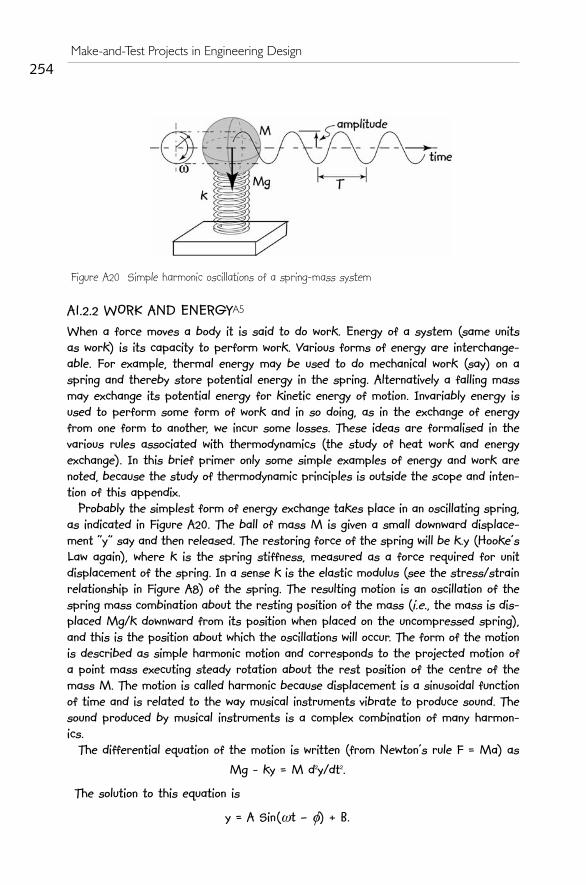
Probably the simplest form of energy exchange takes place in an oscillating spring,as indicated in Figure A20. The ball of mass M is given a small downward displace-ment “y” say and then released. The restoring force of the spring will be k.y (Hooke’sLaw again), where k is the spring stiffness, measured as a force required for unitdisplacement of the spring. In a sense k is the elastic modulus (see the stress/strainrelationship in Figure A8) of the spring. The resulting motion is an oscillation of thespring mass combination about the resting position of the mass (i.e., the mass is dis-placed Mg/k downward from its position when placed on the uncompressed spring),and this is the position about which the oscillations will occur. The form of the motionis described as simple harmonic motion and corresponds to the projected motion ofa point mass executing steady rotation about the rest position of the centre of themass M. The motion is called harmonic because displacement is a sinusoidal functionof time and is related to the way musical instruments vibrate to produce sound. Thesound produced by musical instruments is a complex combination of many harmon-ics.
The differential equation of the motion is written (from Newton’s rule F = Ma) as Mg - ky = M d2y/dt2.
The solution to this equation is
y = A Sin(wt – f) + B.
254Make-and-Test Projects in Engineering Design
Figure A20 Simple harmonic oscillations of a spring-mass system

Differentiating this solution twice and substituting into the original equation yields
and B = k/Mg = the original displacement of the spring by M when at rest. The frequency of oscillation
f = w/2p
and the period
T = 1/f. The amplitude of the oscillation is found by substituting into these equations the
initial conditions.Clearly, when the mass M is at either extreme of its motion, the spring will have
potential energy stored in it. This potential energy is then exchanged with the massto accelerate it towards the centre of motion where the mass will have maximumkinetic energy. In this simple example we have neglected the mass of the spring. Itis an instructive exercise (left for the enthusiastic reader) to consider the influenceof the spring mass on the resulting motion.
The value f is a property referred to as the natural frequency or fundamental fre-quency of spring-mass systems. The form of the relationship
may be applied in a wide variety of mechanical systems where we can identify thestiffness k and the vibrating mass M. As a simple example we can apply this fun-damental concept to the vibration of the beam of Figure A10. From the deflection for-mula given d = PL3/(48EIzz) we find that
k = P/d = 48 EIzz/L3.Consequently for that beam carrying a load of P and having a self mass M we can
write for the natural frequency of lateral vibrationAs an instructive exercise (left for the enthusiastic readers) show that the natural
frequency of lateral vibration is approximately 61 Hz for a simply supported steelbeam with the following properties: L = 1 m, 0.05 m x 0.05 m cross section, carryinga load of 100 N (Steel has a density of 7840 kg/m3).
Another type of system that exhibits harmonic oscillations is a simple pendulum.When the mass of the pendulum is released from some height, its potential energyis converted to kinetic energy of motion and in turn this is reconverted into potentialenergy as the pendulum swings back to its starting point.
255Appendix A1 – A Primer on Mechanics
ω ,=k
M
fk
M=
1
2π
fEI
M P g Lzz•
( )•.=
+1
2
483π

Figure A 21 shows a simple pendulum executing small angle oscillations where y isof the order of 5o. The need for this simplification will become clear when we carryout the simplified analysis of motion for this pendulum.
At location (a) the pendulum mass has potential energy of MgH. At location (b) themass has lost its potential energy, but gained kinetic energy of Mv2/2.
If the pendulum suffers no losses, then we can equate the two energies and findthat
gH = v2/2 (the mass terms cancelling).This energy exchange continues indefinitely if the pendulum experiences no losses.
The differential equation for this case is found by applying Newton’s rule for circu-lar motion, Torque T = J d2y/dt2, where J in the case of the simple pendulum shownin Figure A21 is ML2, because the mass M is assumed concentrated at its centre.
Torque T = L. M.g. sin y = M. L2. d2y/dt2, and simplifying this we get
g/L y – d2y/dt2 = 0, where we have substituted y for Sin y when y is sufficiently small (as indicated
earlier).This differential equation is of the same form as that found for the spring-mass
system above and the pendulum will perform simple harmonic oscillations for smallvalues of y. The period of oscillation is T and depends only on the length L.
This is why the simple pendulum is such a fine timekeeper. Considerable effort wasdevoted by early clockmakers to maintaining L constant, independent of weather con-ditions.A6 As a result a commonly used metal for pendulum arms in clocks is invar(short for invariant), a nickel–iron alloy that has been named for its tolerance tomodest temperature changes.
Figure A22 shows schematically the behaviour of a bouncing ball dropped onto ahard surface with some initial horizontal velocity. The soft rubber ball, as it fallstowards the hard surface, will exchange some of its potential energy for kinetic ener-
256Make-and-Test Projects in Engineering Design
A6 See, for example, Sobel (1995), the story of James Harrison, the inventor of the marine chronometer.
Figure A21 Simple pendulum Figure A22 Bouncing ball
T = 2 /gπ L

gy and at impact into yet another form of energy, stored elastic energy. The wholeprocess will reverse itself with some loss in both elastic recovery and in air resist-ance. The loss in elastic recovery is measured by the “coefficient of restitution”(rebound height/drop height) a property of the elastic material. For the case exam-ple shown in Figure A22 the coefficient of restitution is h/H. There are some mate-rials with coefficients of restitution close to unity and the ball in those cases willreturn to almost the original height from where it was released. Some typical coefficients of restitution are:
• Basketball = 0.66,
• Baseball = 0.54,
• Golf ball = 0.75. Some simple expressions for energy are:• The potential energy of a mass M at height H = M x g x H, where g is the
acceleration due to gravity;
• Kinetic energy of a mass m moving with velocity v = m x v2/2;
• Kinetic energy of a flywheel rotating at angular velocity w with mass momentof inertia J is Jw2/2;
• Potential energy of a spring of stiffness k Newton/meter compressed (ordeflected) by L meters = k x L2/2;
• Thermal energy change in a mass M of liquid when this mass experiences atemperature change of DT = M x s x DT, where s is called the specific heatand is a property of the liquid.
Energy available from burning fuel materials is based on the energy content of thespecific fuel and the rate of burning. For example, paraffin (the basic fuel content ofcandle wax) has 42 kJ/gm of specific fuel energy. As an instructive exercise we couldestimate the power (rate of working or rate of dissipating energy) available from acandle. The exercise requires that we burn a candle and time the rate of loss of can-dle material over some period of time.
A1.3 VERY ELEMENTARY GAS DYNAMICSA7
Inasmuch as a compressed gas may be used as a primary energy source in MaTproject construction, we need to define and explore some basic ideas about com-pressed gas behaviour.
Almost all the basic behaviour of gases was developed by scientists in the eigh-teenth and nieteenth centuries, when performing experiments that involved heatingand pressurizing gases. The Encyclopedia Britannica notes:
Among the most obvious properties of a dilute gas, other than its low densitycompared with liquids and solids, are the great elasticity or compressibility
257Appendix A1 – A Primer on Mechanics
A7 There are many useful references that help to introduce this topic more deeply than is possible in thisbrief exposition. See, for example, Zucker and Biblarz (2002); Hodge and Taylor (1999); Reiner-Decher(1994); Jones and Dugan (1996); Mayhew and Hollingsworth (1996); Moran and Shapiro (2000).

and its large volume expansion on heating. These properties are nearly thesame for all gases and … can be described quite accurately by the followinguniversal equation of state:
pv = RT . This expression of behaviour pv = RT is known as the “ideal gas law”. Although most
gases behave very closely according to this law, there are some small variations fromit at low temperatures. In this expression p = pressure, v = “molar volume”, T is the“absolute temperature” and R is the universal gas constant.
In order to continue this discussion we need to define some of these basic ideas.The general view of gas behaviour is based on the idea that the molecules of gas ina given contained volume of gas are all moving and colliding and bumping into the wallsof the container. Figure A23 is a schematic picture of a gas contained in a rectangu-lar vessel.
The idea of very low temperatures has fascinated physics researchers since it wasrealised that all matter behaves strangely when temperatures are cooled to nearabsolute zero. The adopted value for zero Centigrade on the absolute temperaturescale is 273.15 K (for Kelvin, a temperature scale named after Lord Kelvin of Largs,also known as William Thompson; 1824–1907, Scottish engineer and physicist), corre-
258Make-and-Test Projects in Engineering Design
Figure A23 Schematic picture of a gas. The molecules of the gas moveabout in their container. For “perfect gases” the motion becomes morerapid as temperature increases and all motion will cease and the “per-fect gas” gas will take up zero volume at the “absolute zero” of thetemperature scale
Figure A24 The Kelvin absolute temperature scale (shown logarithmically). Triton is the largestsatellite of Neptune and mainly consists of nitrogen ice

sponding to the temperature at which solid, liquid and vapour phases of water are inequilibrium with each other. This “triple point” of water occurs at 0oC or 32oF and273.15 K (absolute) to make the “ideal gas law” the simple form it is. Althoughabsolute zero (-273.15oC)cannot be reached, temperatures near this value have beenattained in laboratory experiments. The scale of temperatures shown in Figure A24is due to Professor Michael Lea, The Low Temperature Physics Group, University ofLondon.
Molar volume is the volume of “one gram molecule” of a gas, where the gram–mol-ecule measure is the molecular number of the gas in grams. For air, a mixture ofoxygen and nitrogen, the average mole is 29 gm and even though it is a mix of twogases, the behaviour of the mixture closely follows the ideal gas law above.
The ideal gas law is a combination of three earlier laws. The first one is Boyle’slaw, named after the Anglo-Irish scientist Robert Boyle (1627–1691), who in 1662 dis-covered that, at constant temperature, the volume of a gas is inversely proportionalto its pressure. The second law is due to Jaques-Alexandre-Cesar Charles(1746–1823), a French physicist, who discovered that, at constant pressure, a givenquantity of gas has a volume directly proportional to its absolute temperature. Thethird law is that due to Amadeo Avogadro (1776–1856), an Italian physicist, whoshowed that, at a given temperature and pressure, equal volumes of gases containthe same number of molecules. This number (approximately) 6 x 10²³ is calledAvogadro’s number. For example, the molecular weight of oxygen is 32, and hence 32gm of oxygen at 0oC (273 K) and atmospheric pressure (usually referred to as “stan-dard temperature and pressure” or STP) contains 6 x 10²³ molecules. R is the univer-sal gas constant and has the value 8.3143 J/mole oK.
Now applying the ideal gas law, we can confirm that one gram molecule of oxygenhas a “molar volume” of 22.4 litres. Similarly, one mole of air has a mass of 29 gmand has a volume of 22.4 litres. Two other definitions relate to the heat energy need-ed to raise the temperature of a gas. There are two “specific heats” defined andthey are denoted Cp and Cv.
Cp, as the subscript implies is the heat energy required to raise the temper-ature of a mass of gas by one degree Centigrade (or Kelvin), while the gas ismaintained at constant pressure.
Cv is the specific heat defined for the gas at constant volume. These two con-stants for any gas are related by the universal gas constant as R = (Cp – Cv).
We can now examine the behaviour of compressed air as an energy source. A use-ful form of compressed air energy source is offered by a plastic 1 litre beverage bot-tle. With a suitably modified bottle top, the air in the bottle may be pressurised toabout two atmospheres, with either a bicycle pump or a small portable electric pump.If now we have a means of releasing the compressed air to do mechanical work, theestimate of available energy is approximated by assuming that the compressed airis exhausted to atmospheric pressure. In that case the work done on the environ-ment by the compressed air is the same as the work done by the environment incompressing the air. Figure A25 is a plot of pressure against volume for a gas. Thework done in compressing the air is the area under the graph or
259Appendix A1 – A Primer on Mechanics

The shaded area under the curve is the work done by the environment on the gasas it is being compressed. We assume the ideal condition that all this work can berecovered as the gas is permitted to expand freely. If the expansion takes placerapidly, as would be the case when the gas is unconstrained, then the expansion (com-pression) curve is said to be “adiabatic” and the index of expansion (compression) isg = Cp/Cv. For air the value of g is approximately 1.3 and the relationship between
pressure and volume is pvg = constant. For the case of 1 litre air compressed to (say) two atmospheres and then permit-
ted to expand into atmospheric air, the values of volume and pressure are:p1 = 206,000Pa; p2 = 103,000;
v1 = 10-3m3; v2 = (p1 v1g /p2)-g = 1.7 x 10⁻³m3.
The resulting work done by the expanding gas
w = p1 v1g [ v21-g – v11
-g]/(1 – g),
= 101.5 J.If we take the “very simple” approximation of considering the curve in Figure A25
as a straight line, then we find the shaded area to be (v2 – v1)(p1 + p2)/2 = 108 J.
Similarly, for a balloon, the work done in expanding from 2.5 kPa above atmospher-ic to atmospheric pressure is provided by the following data:
p1 = 105,400Pa; p2 = 103,000Pa;
v1 = 6.4 x 10⁻³m3; v2 = (p1 v1g /p2)-g = 6.5 x 10⁻³m3.
The resulting work done by the expanding gas
w = p1 v1g [ v21-g – v11
-g]/(1 – g) = 12 J.We can also examine the behaviour of air as a spring by considering a simple
experiment using a piston and cylinder arrangement shown schematically in Figure
260Make-and-Test Projects in Engineering Design
Figure A25 Pressure volume curve for air whenbeing compressed from one atmosphere to twoatmospheres
Figure A26 Gas “spring” behaviour
w pdvp
p.=
1
2
∫

A26. The air in the cylinder is initially compressed to p1 and then the piston is movedto compress the air further by decreasing the volume of the contained air. Considerthe length of the initial volume to be L and the compression to be (say) DL, the areaof the piston remaining constant at A.
The increase in force on the piston may be calculated by assuming that the com-pression is adiabatic. This means that no heat is either absorbed or released by thegas during compression. This is a fair assumption if the compression is small andoccurs rapidly.
F1 = p1 x A; v1 = A x L; v2 = A x (L – DL).
p2 = (p1 v1g /v2g ) = p1 [ L/(L – DL)]g.
F2 = p2 x A.
k = (F2 – F1)/DL. (k is the spring constant or elastic modulus of the air
spring) = A x p1 [ 1/(1 – DL/L)g]/DL.
As a result of this expression for thespring constant k of an air spring, the valueof k will be a function of the initial pressurein the spring. In this way air, or gas, springsmay be modified during operation byincreasing or decreasing the pressure with-in the spring. In some automobiles thiseffect is used as a means of providing vari-able rate suspension systems. For L = 100mm, DL = 10 mm and A = 100 mm2, thespring constant is plotted against initial
pressure p1 in Figure A27. Clearly, as expected from the equation for k, and indicat-ed in Figure A27, air-spring behaviour is quite linear for small displacements.
A1.4 NEWTON OR ARISTOTLE?Our understanding of the way mechanics operated in our universe, based on Newton’sLaws, has remained virtually unchallenged for nearly 300 years. The Newtonian viewof mechanics still remains quite appropriate for most situations, other than thoseinvolving speeds close to the speed of light. According to Newton (who, according toStephen Hawking, was not a very nice manA8), bodies moving at constant speed haveall the forces acting on them in perfect equilibrium. Moreover, constant accelerationof a body requires a constant (unchanging) force to act on it. Now, these ideas seemrelatively easy to understand in simple situations. Surprisingly, these same relativelysimple ideas can cause some head-scratching, when introduced into not-so-easy sit-uations. For a considerable time before Newton, the Aristotelian view of the universeof mechanics tended to confuse the concepts of speed and acceleration. Aristotleclaimed that the speed of a body at constant acceleration would depend on itsmass.A9 It is interesting to speculate on how students of mechanics would deal with
261Appendix A1 – A Primer on Mechanics
Figure A27 Air as a spring based on theoperating arrangement shown in Figure A26
A8 Hawking (1998).A9 See the reference to Galileo’s experiments on falling masses in Sobel, (2000).

less than simple situations, where Newton’s Lawsshould be invoked. Studies of some responses by stu-dents, including some university-level participants, byCOLOS,A10 has found that, when faced with these “lessthan simple” situations, many first-time students ofmechanics appear to intuitively adopt the Aristotelianview in favour of the Newtonian view. The following
exercises explore the depth of understanding that students have attained inNewtonian mechanics.
AE1. A new type of train is based on the “maglev” principle of floating thecarriages on rails using magnetic levitation.A11 Figure AE1 shows a schematicsketch of a rail carriage floating on a length of test track. The following aresome questions facing designers of this new form of transport. The conditionsof interest to engineers are as follows: 1. F towards B unchanging; 2. F towards B increasing; 3. F towards B decreas-ing; 4. F towards A unchanging; 5. F towards A increasing; 6. F towards Adecreasing; 7. F zero.Considering that the speeds of the carriage are of order 200 kph (kilometreper hour) and friction and air resistance may be neglected, what will be thespeed and acceleration of the carriage (towards A,B, increasing, decreasing,constant) under the seven conditions described?
AE2. The fusée, a conical pulley device (similar tothat in Figure AE2), was already known to watch-makers in the fifteenth century. It was a deviceused in mass-driven clocks to equalise the clockspring as it wound down. Although it was a simpledevice, its main design failing came from theinescapable stretching of the string attaching themass to the fusée. In modern clocks the fusée wasreplaced by much more complicated escapement
mechanisms. A new invention proposes to use kevlar or glass fibre strings ina fusée (with virtually zero stretch). It is being tested in a vacuum and fric-tion in the supporting bearing may be neglected. Considering the cone angley as the main design variable, the conditions of interest to the designers are:
1. y positive (as indicated in the figure); 2.y negative (the cone increases indiameter away from the bearing); 3. y zero (uniform diameter fusée).For each case what will be the angular speed of the fusée (increasing,decreasing or constant)?AE3. A mass M is attached to a string and rotated overhead with the axis ofrotation vertical. If the string breaks suddenly, what will be the path of themass M once released?
262Make-and-Test Projects in Engineering Design
A10 Härtel (1994); White (1983).A11 See www.maglev2004.cn, the official site for the eighteenth International Conference on Maglev andLinear Drives, held in Shanghai, PRC, October, 2004.
Figure AE1. Maglev test track
Figure AE2. A new type of fusée

To the inexperienced, though inventive designer, the idea of units of meas-ure may seem unnecessarily pedantic in the context of make-and-test proj-ects. The substantive argument for considering units, and (shock, horror!)conversions between units, is that they form part of the formal engineeringlanguage that permits communication between problem specifier and prob-lem solver. In addition, the history of units and their adoption by variousinstitutions and countries provides a fascinating and often illuminatinginsight into human nature “in the large”.
Although difficult to prove, it is likely that even early cavemen used unitsof measure for exchange (e.g., “my cave is the height of two Triceratops” –about 4 metres, or “I wish to trade five spears of the length of a tyran-nosaurus skull” – approximately 1.5 metre). It is certainly true that the com-pilers of the Old Testament used units of measure as in the case of Godinstructing Noah (Genesis 6)
14 Make thee an ark of gopher wood; rooms shalt thou make in the ark, andshalt pitch it within and without with pitch.15 And this is the fashion which thou shalt make it of: The length of the ark
shall be three hundred cubits, the breadth of it fifty cubits, and the height of it thir-ty cubits. A cubit is an ancient unit of length measure used throughout the Old
Testament. It originates as early as 3000 BC (about 5000 years ago), and isthe distance from the elbow to the end of the middle finger, approximately454 – 555 mm. By 2500 BC this had been standardised in a royal master cubitof about 520 mm. This cubit was divided into 28 digits (roughly the widthof a finger) which could be further subdivided into fractional parts, thesmallest of these being only just over a millimetre.
Early measurements would make use of “natural measures” as in the sur-veyor’s rod or chain, the grain merchants bushel or the precious stone meas-ure of carat. The last is derived from the carob seeds used in the trading ofprecious stones, now standardised as 200 mg.
263
APPENDIX A2UNITS OF MEASUREMENT ANDCONVERSION FACTORS
In Xanadu did Kublai Khana stately pleasure-dome decree,where Alph, the sacred river, ranthrough caverns measureless to mandown to a sunless sea,so twice five miles of fertile groundwith walls and towers were girdled round…Samuel Coleridge Taylor 1798

Systems of Measurement and StandardisationA2.1
Initially the main types of measures were for lengths (distances), areas (forexample, measuring parcels of land or quantities of cloth), volumes (forexample, measuring quantities of fluids or grains), mass and time. As technol-ogy changed, other units of measure became necessary, including tempera-ture, heat, electric current or electric potential and illumination level.
In England units of measurement became standardised in the thirteenthcentury, though variations (and abuses) continued until long after that. Forexample, up until 1824 there were three different gallons (ale, wine and corn)when the UK gallon, still in current use, was standardised at approximately277 cubic inches (4.545 litres in SI units).
Initially the United States adopted the English system of weights andmeasures, with a few minor differences. For instance, the wine-gallon of231 cubic inches was used instead of the English one of 277 cubic inches.The UK inch measured 2.53998 cm whereas the US inch was 2.540005 cm.Both were standardised at 25.4 mm in July 1959.
In France the metric system officially started in June 1799. The unit oflength was the metre which was defined as being one ten-millionth part ofa quarter of the earth’s circumference. The production of this standardrequired a very careful survey to be done which took several years. To per-mit proper standardisation of measurements and units the BureauInternational des Poids et Mesures (BIPM) was set up by the Convention of theMetre and has its headquarters near Paris, France.
The Convention of the Metre, signed in Paris in 1875 by representatives ofseventeen nations and modified slightly in 1921, is a diplomatic treaty whichgives authority to the General Conference on Weights and Measures(Conférence Générale des Poids et Mesures, CGPM), the InternationalCommittee for Weights and Measures and the International Bureau ofWeights and Measures to act in matters of world metrology, particularlyconcerning the demand for measurement standards of ever increasing accu-racy, range and diversity, and the need to demonstrate equivalence betweennational measurement standards.
The Bureau’s mandate is to provide the basis for a single coherent systemof measurements throughout the world, traceable to the InternationalSystem of Units (SI). This task takes many forms, from direct dissemina-tion of units (as in the case of mass and time) to coordination through inter-national comparisons of national measurement standards (as in length, elec-tricity, radiometry and ionising radiation).
In all the BIPM recognises seven basic units of measure under theInternational System of Units, Système International d'unités, or SI system, andall other measures and units are derived from these.
264Make-and-Test Projects in Engineering Design
A2.1 Source: www.bipm.org: a wonderful SI brochure is freely available from this site. See alsohttp://physics.nist.gov/cuu/index.html for the USA version of standard system of units.

The Seven Fundamental SI Units• Length – The metre (m) is the length of the path travelled by light
in vacuum during a time interval of 1/299,792,458 of a second.
• Mass – The kilogram (kg) is the unit of mass; it is equal to themass of the international prototype of the kilogram.
• Time – The second (s) is the duration of 9,192,631,770 periods ofthe radiation corresponding to the transition between the twohyperfine levels of the ground state of the cesium 133 atom.
• Electric current – The ampere (A) is that constant current which, ifmaintained in two straight parallel conductors of infinite length,of negligible circular cross-section, and placed 1 m apart in vacu-um, would produce between these conductors a force equal to 2x 10⁻⁷ Newton per metre of length.
• Temperature – The Kelvin (K) unit of thermodynamic temperatureis the fraction 1/273.16 of the thermodynamic temperature of thetriple point of water.
• Quantity of elemental material – The mole is the amount of substanceof a system which contains as many elementary entities as thereare atoms in 0.012 kilogram of carbon 12. When the mole is used,the elementary entities must be specified and may be atoms, mole-cules, ions, electrons, other particles or specified groups of such par-ticles.
• Luminous intensity – The candela (cd) is the luminous intensity, ina given direction, of a source that emits monochromatic radiationof frequency 540 x 1012 Hertz and that has a radiant intensity inthat direction of 1/683 Watt per steradian.
Some Derived Units and DimensionsAll units of measuring physical quantities may be derived from these sevenfundamental units. Table A2.1 lists some of the derived units and their sym-bols. Area, density, force and pressure are typical derived units. The SI agreedformat for all the units and their symbols is in the singular. Typically, tenmetre (10 m), or ten kilogram (10 kg), rather than ten metres, or ten kilo-grammes. In addition, each quantity has associated dimensions in mass (M),length (L) and time (T). These dimensions permit the evaluation of rela-tionships between derived units. Table A2.1 lists the dimension for all thederived units. As an example, the unit of force is Newton, derived by thedefinition that it is the force required to accelerate a mass of one kilogram at onemetre per second per second (invoking Newton’s law, F = Ma). Its dimen-sions then become [MLT-2]. Work is the quantity derived from the definition
265Apendix A2. Units of Measurement and Conversion Factors

that one unit of work is performed by one Newton force moving one metre. Hencethe units of work are [ML2T-2] (i.e., force x length). Kinetic energy is theenergy of a moving body of mass m at velocity v. Hence KE = mv2/2. Thedimensions of KE are [ML2T-2], or the same as the dimensions for work.Clearly, these two derived quantities, work and energy, have the same dimen-sions and indeed they are measured in the same units of joule (J).
The dimensions of units also permit the easy interchange between differ-ent sets of units. As an example consider the quantity stress expressed in theold civil engineering unit of kip (kilo pound per square inch) to be convert-ed to the SI unit of Pascal (Pa = Newton/m2).
1 pound force = 0.454 kg x 9.8 (the gravitational constant) N,
1 inch = .0254 m,
266Make-and-Test Projects in Engineering Design
Table A2.1 Derived quantities and their dimensions
Quantity Unit Symbol Dimensions
Area Square metre m2 L2
Volume Cubic metre m3 L3
Velocity (speed) Metre per second m s-1 LS-1
Acceleration Metre per second per sec-ond m s-2 LS-2
Density Kilogram per cubic metre kg m-3 ML-3
Concentration Mole per cubic metre mol m-3 ML-3
Specific volume Cubic metre per kilogram m3 kg-1 L3M-1
Current density Amperes per square metre A m-2 A L-2
Force Newton N MLT-2
Work joule J ML2T-2
Power (rate of working) Watt (joule/second) W ML2T-3
Pressure Newton per square metre,or Pascal Pa ML-1T-2
Stress Newton per square metre,or Pascal Pa ML-1T-2
1000 0 454 9 82
2
2
[ ]
[ ]
. ( .lb
in
kg lb)MLT
L
−⎡
⎣⎢
⎤
⎦⎥ =
× ( .)
. ( / )
gravitational•acc
metre inch
n
02542 2 2
==⎡
⎣⎢
⎤
⎦⎥
−
68942
2
[ ]
[ ].kPa
MLT
L

In many situations there is a need to express quantities in very large orvery small units. The SI system recommends standard prefixes for denotingvarious orders of 10 as the multiplier of the basic unit. For example, onekilowatt, denoted kW is 1000 W. Table A2.2 lists the standard prefix set rec-ommended by SI, virtually all prefixes differing by three orders of magni-tude (i.e., Giga is three orders of magnitude larger than mega and pico isthree orders of magnitude smaller than nano).
There are some important units used internationally that have not yield-ed to SI standardisation. The following are some examples:
• knot = 1 nautical mile per hour = (1852/3600) m/s; The nauticalmile is a special unit employed for marine and aerial navigation toexpress distance. The conventional value given above was adopt-ed by the First International Extraordinary HydrographicConference, Monaco, 1929, under the name “International nau-tical mile”. As yet there is no internationally agreed symbol. Thisunit was originally chosen because one nautical mile on the sur-face of the Earth subtends approximately one minute of angle atthe centre.
• are = 100 m2, a unit still in common use in the form hectare, shortfor hecto-are or 104 m2.
267Apendix A2. Units of Measurement and Conversion Factors
Table A2.2. Prefixes used to denote orders of magnitude in unitsPrefix Symbol Power of tenyotta Y 24zetta Z 21exa E 18peta P 15tera T 12giga G 9mega M 6kilo k 3hecto1 h 2deca1 da 1
0 (100 = 1)deci1 d -1centi1 c -2milli m -3micro m -6nano n -9pico p -12femto f -15atto a -18zepto z -21yocto y -24Note 1. These prefixes are not recommend by SI and are included because theyare still in use by some systems of units.

• bar – as a unit of pressure, approximately in multiples of standardatmospheric pressure (atmospheres as measured by a barometer –hence bar). 1 bar = 0.1 MPa = 100 kPa = 1000 hPa = 105 Pa.
• yard – still used in expressing distances (a mile = 1760 yard); 1yard = 0.9144 metre; same in the US and UK.
• pound – for measuring quantity of substances = 0.453 592 37 kilo-gram; same in the US and UK.
• US gallon (liquid) – volumetric measure = 3.785,411,784 litre.• UK gallon = 4.546,09 litre; different from US gallon.• Ton – a unit of mass = 2000 pound (short ton) in US and 2240
pound (long ton) in UK. • Note that the SI unit of megagram (Mg = 106 gm) is the Tonne.• The international unit of thermal energy is the calorie (cal)
1 cal = 9.80,665 joule.• The speed of light in vacuum = 299,752,458 ms-1.• Acceleration due to gravity = 9.806,65 ms-2.• Newton’s gravitational constant G = 6.674,2E-11 m3kg-1s-2.
Conversion Factors
268Make-and-Test Projects in Engineering Design
Quantity SI unit To get (other unit) Multiply SI unit by
Mass kg pound (lb) 2.204 62ounce (oz) 35.274 0
Length metre foot (1/3 yard) 3.280 84inch (1/12 foot) 39.370 1
kilometre (km) mile (5280 ft) 0.621 37Volume litre (l)(=E-03 m3) gallon US 0.264 172
gallon UK 0.219 969cubic foot (ft3) 3.5315E-02
Density kilogram/metre3 (kg m-3) pond/cubic foot (lb ft-3) 6.242 8E-02Force Newton (N) pound force (lbf) 0.224 809Moment Newton metre (Nm) foot pound force(ft lbf) 0.737 562Pressure/stress Pascal (Pa = N m-2) pound force/in2 (psi) 1.450 4E-04
pound force/ft2(psf) 2.088 5E-02bar 1 E-05
millimetre Mercury(mm Hg) 7.500 6E-03
inch water (in H2O) 4.014 6E-03Tonne/metre2 (Tm-2) UK Ton/ft2 9.143 789E-05
US Ton/ft2 1.024104E-04bar Atmosphere (atm) 0.986 923
Work/energy joule (J) British thermal unit (BTU) 9.478 2E-04Calorific heat unit (CHU) 5.2657E-04
Power Watt (Js-1) Horse power (Hp) 1.341 0E-03

269
APPENDIX A3SOME PROPERTIES OF PLANE SECTIONS ANDANSWERS TO SELECTED EXERCISES
Two relationships of importance are:Polar 2nd moment of area Ip = Ixx +Iyy, and theParallel Axis Theorem, Iz = Iw + Ah2, where Iz is thesecond moment about axis ZZ, Iw is second momentabout axis WW, with ZZ and WW parallel and h isthe distance between them.

ANSWERS TO SELECTED EXERCISESDoubt is not a pleasant condition, but certainty is absurd. VoltaireEverything should be made as simple as possible, but not simpler.Einstein
E2.1 Newton’s bucketA simple experiment, conducted by Newton, involvessomewhat mysterious results. Figure A3.1 shows abucket which contains water and is suspended by acord so it is free to rotate around its centreline. Thebucket has been turned many revolutions around thecentreline so the cord is twisted and exerts a torqueon the bucket. The surface of the water is flat beforethe bucket commences to rotate under the action ofthis torque and when the bucket is held motionless rel-ative to Earth.
When the bucket is permitted to rotate as the twisted rope unwinds, thewater gradually recedes from the middle of the bucket and rises up at thesides of the bucket creating a concave (parabolic) surface as indicated in thefigure. Newton's experiment with the rotating vessel of water informs us thateven though we do not exert any rotational forces on the body of water (aswe would on a mass connected to a string rotating about a centreline), it stillexperiences centrifugal forces in the Earth’s gravitational field. The motion isunderstood in fluid mechanics as a”free vortex”.
E2.2 Einstein’s Elevator
Einstein realised that frames of reference and relativemotion are vital concepts. He conducted a thought exper-iment in which he considered a person in an elevatorwhile the elevator’s acceleration was up, down or zero.The effect on the person in the elevator (the observer)was the apparent increase or decrease in mass in spiteof there being no change in real mass of the person. Ifthe elevator reaches 9.81 ms-2 downward, the observerwill appear to be weightless.
E2.3 Schrödinger’s Cat
Erwin Schrödinger (1887–1961) was a quantum physicist who used the catexample as an illustration of uncertainty in quantum mechanics. He proposedin 1935 a demonstration of the apparent conflict between what quantum the-ory tells us is true about the nature and behaviour of matter on the micro-scopic level and what we observe to be true about the nature and behaviourof matter on the macroscopic level.
270Make-and-Test Projects in Engineering Design
Figure A3.1 Newton’s BucketExperiment
Figure A3.2 Einstein’sElevator
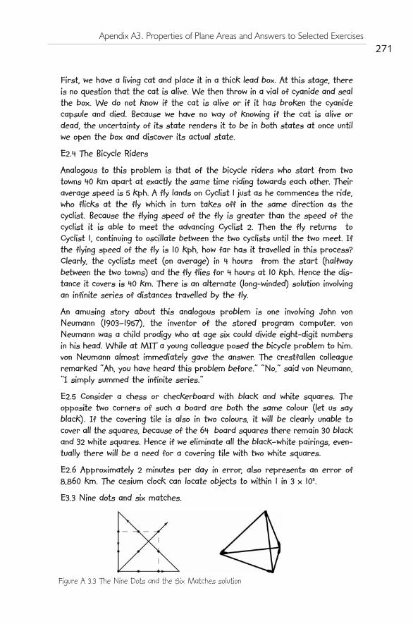
First, we have a living cat and place it in a thick lead box. At this stage, thereis no question that the cat is alive. We then throw in a vial of cyanide and sealthe box. We do not know if the cat is alive or if it has broken the cyanidecapsule and died. Because we have no way of knowing if the cat is alive ordead, the uncertainty of its state renders it to be in both states at once untilwe open the box and discover its actual state.
E2.4 The Bicycle Riders
Analogous to this problem is that of the bicycle riders who start from twotowns 40 km apart at exactly the same time riding towards each other. Theiraverage speed is 5 kph. A fly lands on Cyclist 1 just as he commences the ride,who flicks at the fly which in turn takes off in the same direction as thecyclist. Because the flying speed of the fly is greater than the speed of thecyclist it is able to meet the advancing Cyclist 2. Then the fly returns toCyclist 1, continuing to oscillate between the two cyclists until the two meet. Ifthe flying speed of the fly is 10 kph, how far has it travelled in this process?Clearly, the cyclists meet (on average) in 4 hours from the start (halfwaybetween the two towns) and the fly flies for 4 hours at 10 kph. Hence the dis-tance it covers is 40 km. There is an alternate (long-winded) solution involvingan infinite series of distances travelled by the fly.
An amusing story about this analogous problem is one involving John vonNeumann (1903–1957), the inventor of the stored program computer. vonNeumann was a child prodigy who at age six could divide eight-digit numbersin his head. While at MIT a young colleague posed the bicycle problem to him.von Neumann almost immediately gave the answer. The crestfallen colleagueremarked “Ah, you have heard this problem before.” “No,” said von Neumann,“I simply summed the infinite series.”
E2.5 Consider a chess or checkerboard with black and white squares. Theopposite two corners of such a board are both the same colour (let us sayblack). If the covering tile is also in two colours, it will be clearly unable tocover all the squares, because of the 64 board squares there remain 30 blackand 32 white squares. Hence if we eliminate all the black–white pairings, even-tually there will be a need for a covering tile with two white squares.
E2.6 Approximately 2 minutes per day in error, also represents an error of8,860 km. The cesium clock can locate objects to within 1 in 3 x 10⁸.
E3.3 Nine dots and six matches.
271Apendix A3. Properties of Plane Areas and Answers to Selected Exercises
Figure A 3.3 The Nine Dots and the Six Matches solution

The nine dots and the six matches problems illustrate the nature of delimita-tion in solving puzzles and problems. Here the solutions really represent casesof “thinking outside the square”.
E3.5 Marbles in a bag
Number the bags from 1 to 10 and take one marble from bag 1, two from bag2 three from bag 3, and so on. If the 9 gram marbles are in bag N then thetotal mass will be 10 + 20 + 30 +… 9N +… = (500 – N) gm.
E6.1 The specific heat of water (Cp) is 1 Calorie gm-1 degree-1. If the tem-perature of the cup of tea is (say) 80oC, that makes it about 60oC above theaverage room temperature. If we could recover the whole of this thermalenergy from the cup of tea then we could write
m.Cp.DT = m.g.h, or 1000 x 60 x 4.187 = 9.81 h
h = 4.187 x 1000 x 60/9.81 = 26 km!
An amusing party trick (among a collection of engineers) is to ask some engi-neer this question and ask someone to “guess” the result.
272Make-and-Test Projects in Engineering Design

A
Abdel-Rahman 5Aczel 32Adams 3, 11, 12, 36Advanex Inc. 136Agrawal 21Akao 29alchemy 210, 224Alexander 4, 28, 37, 77Allison 61Ambrose 5American & Efird 92American Petroleum Institute 131American Textile ManufacturersInstitute 92Amirkhan 34Amon 5Ampère 139Antigravity 224Arce-Villalobos 90Archimedes’ Screw 224Atkins 129, 251Australian Urethane and Styrene 89B
Ball in a jet 223Ball operated clocks 224Balmer 197Beitz 9, 21, 204. See also Pahl andBeitzBelloc (Hilaire) 121Biden 5bimetallic strip 132Bisantz 21Blackowiak 52Biblarz 255Boden 39Boguslaw 1Bollay 4
breaking length 16, 88Brown 13Brunning 36Buckminster Fuller 207buckyball 207Bullock 28Bungee–omelette 53Byo 40C
California Screamin 134Calladine 207, 210, 222Campbell 36, 149Can Opener 24Canada Bamboo 91Canter 28Capp 70. See also DePaul andMercerCarver 34castor-oil reaction 46Celts 52Chang 34Chanute 18Chen 21, 61China Syndrome 219Clancey 31Clausing 23Cognitive map 37. See also ConceptmapCohen 29, 31Cohen’s robot 31Cole 61Composites bonding 98Concept map 37Conceptual blockbusting 36Congreve 224, 225Connor-Greene 70Cooper 130Cornpone 71. See also CappCottrell 5
273
INDEX

Courant 221Cox 40Coxeter 221Crick 32, 34Criterion of performance 20, 42, 43,44, 52Crompton 142Crouch 18D
D’Zurilla 34Da Vinci 13. See also LeonardoDaedalus and Icarus 17Daetz 29Danjo 67Davidson 243de Bono 12, 34, 72De Mille 40De Simone 3, 46, 149decision–matrix 28Destination Disaster 5Dickerson 5Dogan 28Drinking bird toy 222Du 61Duckworth 39Dugan 255Durfee 5Dutta 32E
Eddy 5. See also Destination DisasterEdison 17Egelhoff 5Egg–drop 63, 65Einstein 13, 15, 29Energizer Batteries 141Energy sources 58, 63, 66Epstein 40, 149F
Falk 39Field 31, 40Fiolhais 210Fodor 34
Fourdrinier 84Frederiksen 46, 189French 1, 25Fuchs 3, 155fullerenes 207function–structure 20, 24G
Galileo 129, 149, 205, 206, 251, 259Galileo’s finger 251Galvani 139, 141Gedanken 13, 15Gere 126Gladman 46, 189Glickauf-Hughes 149Goetschalckx 28Gruber 39Gryskiewicz 32Güémez 210, 222Guthrie 38H
Handbook of Turbomachinery 210Harrison 36Hart-Davies 210, 225Härtel 260Hauser 23Hawking 241, 259Herring 5Hewitt 130Hibbard 5Hodge 255Hoffmann 61Hollingsworth 255Horn 36Hornby 11Hull 32Hunt 243I
Infeld 29interaction–matrix 21, 28Ishi 67J
274Make-andTest Projects in Engineering Design

Janssen 90Jewkes13Johnson 75Jones 64, 255Jung 32K
Kaisinger 197Kalamaras 28Kaplan 31, 52Kelly 241Khayyám 52King 29Kitchen 70Klein 149Klenk 5Kondratieff 17Korfmacher 40Kurowski 130L
Lancaster 46, 189Lateral Thinking 70, 72Ledsome 23Leonardo 13, 14, 15, 18Leopoldo dei Medici 206Lesjöfors AB 136Lester 70Lewis 6, 46, 73, 189, 204Li’l Abner 70Lienhard 185Likert 39Lillard 40Lin 21Logan 210, 211Longitude 36Longitude Act 36Longitude prize 36Lotz 149Love 5M
maieutic 6Manheim 28Mayhew 255
McFarland 131McKim 3, 36, 40Meccano 11Meno 38Mensch 17mind map 37Miranda 40Mittal 98Mizuno 29Moje 70molded springs 136Montessori 40Moore 41Moran 255Morphology 9, 71Mother Jones 77Motro 207Mumadi 61Myers–Briggs personality type 33Myers–Briggs personality type indi-cator 32N
Nair 61Narri 61natural-resources.ncsu.edu 88Newman 210, 224Ng 28Niku 5No Highway 219Nolan 130Nuclear Energy Agency 130O
Ocean Wave Energy Company 210Odom 5Ohm 139Ord-Hume 210, 223Otsuka 131P
Pahl 9, 20, 21, 22, 204Papastravidis 243Park 210, 223, 224Parmee 28
275Index

Parrott 37Performance Criteria 55, 57, 61, 62,63, 64Perpetual motion 223Perry 36philosopher’s stone 224physics.nist.gov/cuu/index.html 262Piaget 39Pizzi 98Plato 38Pocius 98Pollard 22Popper 11process–description 22product–planning matrix 27Pyrotenax 44Q
QFD 23, 27, 28, 2923. See also quality function
deploymentR
Rabinow 45, 46Radjou 17Rand 52Reiner-Decher 255Reiter-Palmon 36Ressler 5Revere, 213 214reverse engineering 228Rittel 18Robbins 221Roffe-Steinrotter 34Rogers 5Ross 46, 189Rowlands 40S
Samuel 6, 9, 37, 40, 46, 47, 73, 83,126, 189Samuels 12Sawers 18. See also JewkesSeffen 210, 222Setlow 22
Shapiro 255Shawki 5Shockley 45, 46Shute 219Simon 2, 3, 21, 22, 31Smith 4, 77Snelson 208Sobel 35, 36, 254, 259Socrates 6Socratic Dialogue 38, 39, 40Soma Cube 75span of subsystems 22Spicer 40Srinivasan 131Stairs 40Stanford Case Library 155Stanley Kubrick 23state–definition 22Steidel 3, 155Stillerman 18. See also JewkesStrongman 37Structural Adhesives 98superlight gliders. See also Danjoand IshiT
Tangrams 75Taylor 255Team Dynamics 70Tensegrity 207Terninko 29Terzis 37Tex 92Timoshenko 90, 126, 249Tullar 32Turbo generators 211U
Ure 77USPTO 225V
Valiente 210Vaughn 40Vesper 3
276Make-andTest Projects in Engineering Design

Vidal 39Visual thinking 40Viviani 205, 206Volta 139, 140, 141Voneche 39W
Walker 52Wang 64Warman Trophy. 198Watkins 36Watson 32, 34Weber 224Weir 9, 37, 47, 83, 126, 197Wenzel 36Werner 70Wesenberg 32White 46, 189, 260Whitehead 18Wiles 32, 34Williams 107Wohl 219Wood Adhesives 98Wood Handbook 82, 83Wright (brothers) 18, 241www.angelfire.com 64www.bipm.org 262www.centuryspring.com 135www.designmatrix.com 21www.eere.energy.gov/RE/ocean.html210, 211www.humanmetrics.com 34www.maglev2004 260www.motherjones.com 77www.paperloop.com 85www.usq.edu.au/warman_comp 46Wyman 131X
Xanthanite 130Xerox 4Y
Yamaha 40
Z
Zeigler 208Zucker 255
277Index