refrigeration systems - saskpower
TRANSCRIPT

REFRIGERATION SYSTEMS
Energy Efficiency Reference Guide

DISCLAIMER: Neither CEATI International, the authors, nor any of the organizations providing funding support for this work (including any persons acting on the behalf of the aforementioned) assume any liability or responsibility for any damages arising or resulting from the use of any information, equipment, product, method or any other process whatsoever disclosed or contained in this guide. The use of certified practitioners for the application of the information contained herein is strongly recommended. This guide was prepared by Ivor da Cunha P.Eng., LeapFrog Energy Technologies Inc. for the CEATI International Customer Energy Solutions Interest Group (CESIG) with the sponsorship of the following utility consortium participants:
© 2010 CEATI International. All rights reserved.

TABLE OF CONTENTS
Section Page
1 Purpose of this Guide 7
2 How this Guide is Organized 9
a. Quick Start Chapters for Specific Job Functions 9
b. Guide Organization 11
c. Related CEATI Publications 13
3 Introduction 15
a. Common Refrigeration Applications in Business 15
4 Theory Behind Refrigeration 17
a. Heat and Heat Transfer 17
b. Boiling Points and Pressure 18
c. Heat Transfer 18
d. Enthalpy 19
e. Refrigeration System and Pulley Analogy 20
f. Basic Rules to Reduce Energy Wastage 22
5 The Refrigeration Cycle 25
a. Refrigeration Thermodynamics 25
b. The Vapour Compression Cycle 26
c. Key Steps of Vapour Compression Refrigeration 28
d. Component Performance 29
e. Coefficient of System Performance 30
f. Measurement of Efficiency 30
g. Factors Impacting Efficiency 31
6 Compressors 33
a. Positive Displacement Compressors 33
b. Compressor Efficiency 36
7 Evaporators, Condensers and Expansion Valves 39
a. Evaporator Efficiency 39
b. Defrosting Evaporators 39
c. Energy Efficiency and Defrosting 40
d. Condenser Efficiency 40
e. Expansion Devices 41
f. Capacity Control 42
g. Enclosed Motors 42
h. Compressor Lubricating Oil 43
8 Refrigerants 45
a. Refrigerant Characteristics 45
b. Ozone Depletion Potential 46
c. Refrigerant Applications 47
d. Safety and Health Issues 48
9 Purchasing a New Refrigeration System 51

10 Industry Specific Refrigeration Efficiency Tips 53
a. Supermarkets and Food Retail 53
b. Manufacturing and Distribution 53
11 Instrumentation 55
12 Low-Cost No-Cost Refrigeration Improvements 57
a. System Energy Optimization Tips 58
13 Checklist for Operational and Maintenance Improvements 61
a. Day-to-Day Operation 61
b. Routine Maintenance Tips 61
c. Minimizing Parasitic Loads 62
14 Diagnosis Methodology for System Optimization 65
a. Troubleshooting and Fault Tracing 65
b. Refrigeration Logs and Records 66
15 Commissioning and Maintenance 67
a. Baseline Specification 67
b. Commissioning 68
16 Refrigeration Performance Measurements 71
a. Cause and Effect - Symptoms to Look For 74
17 Refrigeration Audit Assessment Worksheet 77
a. Housekeeping Measures 78

b. Low-Cost Measures 80
Appendix A. System Assessment Memory Jogger 83
Appendix B. Refrigeration Codes and Standards 85
Appendix C. Conversion Factors 89
Appendix D. Glossary of Common Refrigeration Terms 91
Appendix E. Key Sector System Efficiency Opportunities 95
a. Ice Rinks 95
b. Supermarkets and Food & Beverage Sectors 97
Appendix F. Bibliography and Web Links 101
a. Print References 101
b. Web Links 102

1. Purpose of This Guide
7
1 PURPOSE OF THIS GUIDE
This guide is aimed at helping you implement energy efficiency methods and practices involving refrigeration systems at your location. The main emphasis is on small to medium systems that operate with refrigerants other than ammonia.
It is common for small- and medium-sized businesses to have piecemeal refrigeration components installed and operating. The guide will also help you to make informed decisions about operating, maintaining or modifying your existing refrigeration system or configuration. It can provide you with some guidance on high-level factors and questions to ask while in the process of designing, constructing or commissioning a new system. This guide does the following:
Characterizes various systems Provides a quick reference on performance
optimization techniques Reviews field performance testing procedures
Caution: As with any electrical or rotating equipment, always use proper safety procedures, ventilation and lockout procedures before operating, testing or servicing refrigeration system equipment.

1. Purpose of This Guide
8

2. How This Guide Is Organized
9
2 HOW THIS GUIDE IS ORGANIZED
This guidebook is intended to provide the fundamental information essential to making informed and educated decisions about the use of energy efficient operation of refrigeration systems.
As with most other process equipment, over the lifetime of a typical refrigeration system, the value of electricity used can exceed the initial cost many times over. Performance optimization of refrigeration offers tremendous potential for energy savings in the industrial, commercial and institutional sectors. By understanding the relationship between energy and functionality, readers can make informed decisions about the procurement, installation, maintenance and operations of refrigeration equipment and systems.
a. Quick Start Chapters for Specific Job Functions
Table 1 outlines the key chapters that a typical specialist would find to be most beneficial.

2. How This Guide Is Organized
10
Table 1 Quick Start Chapters for Specialists
Chapter Ref
rig
erat
ion
P
lan
t O
per
ato
r
Fac
ility
Man
ager
Pu
rch
asin
g
Mai
nte
nan
ce
Sys
tem
Des
ign
er
Ser
vice
Pro
vid
er
Introduction X X X X X X Theory Behind Refrigeration X X X X The Refrigeration Cycle X X X X X Compressors X X X
Evaporators, Condensers and Expansion Valves
X X X X
Refrigerants X X X X X X Purchasing a New Refrigeration System
X X X X
Industry Specific Refrigeration Efficiency Tips
X X X
Instrumentation X X X Low-Cost No-Cost Refrigeration Improvements
X X
Checklist for Operational and Maintenance Improvements
X X X
Diagnosis Methodology for System Optimization
X X X
Commissioning and Maintenance X X X
Refrigeration Performance Measurements
X X
Refrigeration Audit Assessment Worksheet
X X

2. How This Guide Is Organized
11
b. Guide Organization
The guide is organized into standalone and related modules. It is expected and recognized that individual readers of this guide have different levels of knowledge and experience with refrigeration systems and associated components.
The main themes of the guide are:
Refrigeration System Fundamentals, Performance Optimization of Refrigeration Equipment
and Opportunity Strategies, Resources and References, and Getting the Most from this Guide.
Refrigeration System Fundamentals
For readers who may not be familiar with the essentials of the refrigeration cycle and how vapour compression cycles work, the first section provides a brief discussion of terms, relationships, and important system design considerations, as follows:
The main factors for equipment selection and system design are provided, while giving an overview of different types of equipment and their general applications.
Theory of the refrigeration cycle. Energy efficiency concepts are introduced. Relationships between cause and effect when it comes
to refrigeration system optimization.

2. How This Guide Is Organized
12
Performance Optimization of Refrigeration Equipment and Opportunity Strategies
Optimizing the energy performance of refrigeration equipment, in most cases, requires that a “systems approach” be taken. The guide considers factors on the refrigeration production side, as well as the end-use side that can be adjusted or changed in order to optimize energy efficiency and performance.
The guide addresses the main components of a refrigeration system and opportunities to improve the overall system performance.
Refrigeration control methods and energy implications of each are discussed.
Short modules address some of the most common design and operations parameters.
The guide also addresses the key factors and issues in determining the overall lifetime cost of procuring and operating refrigeration equipment.
Adjustable speed drives and how they can save energy and money.
What to look for when identifying inefficient systems. A refrigeration troubleshooting checklist, worksheets
and memory joggers.
Resources and References
The guide also has publication and internet references with hyperlinks for many useful sources of assistance that can help readers learn more about refrigeration systems.

2. How This Guide Is Organized
13
Getting the Most from this Guide
There are many excellent textbooks and reference manuals regarding refrigeration systems. This guide is not intended to replace the reference books, but rather to supplement the discussion regarding energy efficiency.
This guide has been written with you in mind. We have adapted the material to accommodate the following:
Learning styles that require short bursts of relevant information to assimilate knowledge
Need for practical knowledge in addition to the theoretical knowledge the reader may or may not already have
Use of the Internet or online tools for learning new skills or acquiring knowledge
Reinforcement of key messages and “takeaway” points
c. Related CEATI Publications
CEATI has published other research reports related to refrigeration technology and utilization, including publications shown in Table 2.

2. How This Guide Is Organized
14
Table 2 CEATI Refrigeration Publications
CEATI Report Number
CEATI Report Title
9129 U 858 Potential Electricity Savings in Ice Arenas and Curling Rinks Through Improved Refrigeration Plant (Volumes I & II)
9208 U 966 B A Food Industry Guide to CFC and HcFC Refrigeration Phase-Out (Volume II)
9208 U 966 Capitalizing on the Energy Saving Opportunities Presented by CFC and HCFC Phase-Out in Non-Domestic Refrigeration (Volume I)
T011700 7005
Advanced Supermarket Refrigeration/Heat Recovery Systems
T021700 7009
Best Available and Emerging Refrigeration Technologies

3. Introduction
15
3 INTRODUCTION
Refrigeration is the process of removing heat from a lower-temperature zone and discarding it to a higher-temperature zone. Heat naturally flows from hot to cold. Refrigeration is therefore the opposite of the natural flow of heat. It has many applications in everyday life including chilling, freezing, and air-conditioning.
Refrigeration systems range in size from sub-horsepower to tens of thousands of horsepower in capacity. This guide will focus on small- to medium-sized systems, which, for the most part, excludes ammonia-driven refrigeration equipment.
a. Common Refrigeration Applications in Business
Cold Storerooms
Cold storerooms generally have the compressors and condensers situated outside the room itself. A key factor is to ensure adequate ventilation for air-cooled units to allow the heat to dissipate.
Process Cooling
Refrigeration is commonly used in food and beverage and plastics industries. Precise temperature control is necessary for the health and safety of products, as well as the quality of parts produced.

3. Introduction
16
Standalone Units
In standalone refrigerators, display cabinets, or freezers, the compressor and condenser are typically situated at the rear of the cabinet. While the evaporator is generally located inside the cooled volume, the condenser takes advantage of a large side panel to maximize heat exchange.
Recreational
Refrigeration is used to supplement or to replace applications for ice and snow-making in skating and curling rinks, and ice-making operations. The vast majority of these systems are ammonia-based.

4. Theory Behind Refrigeration
17
4 THEORY BEHIND REFRIGERATION
Modern refrigeration systems operate using a vapour compression cycle. This cycle takes advantage of the following five fundamental physical principles:
The natural flow of heat is from a hot to a cold zone. In order to change the state of a substance from liquid
to gas through boiling or evaporation, heat energy is required.
In order to liquefy or condense a gas into a liquid, heat must be removed.
As the pressure increases, the boiling point or condensing point generally increases.
As the pressure decreases, the boiling point or condensing point generally decreases.
a. Heat and Heat Transfer
Heat is a common form of energy produced from chemical or physical sources. The heat contained in a substance is its thermal or internal energy. Changes to this internal energy may show up as a phase change between the solid, liquid or gaseous state.
The substance may also have other forms of potential or kinetic energy, depending on pressure, position and movement. Enthalpy is the sum of these substances’ internal energy and flow work. In most processes where there are steady-state or no flow, enthalpy will be the quantity of heat gained or lost.

4. Theory Behind Refrigeration
18
b. Boiling Points and Pressure
The temperature at which a liquid boils varies with the pressure. As the pressure decreases in a system, so does the boiling point. For example, at standard atmospheric pressure (1.013 bar), water boils at 100°C. If the pressure is reduced to 0.2 atmospheres, the boiling point of water will be approximately 60°C.
For a given substance, the boiling point is limited by the critical temperature at the upper end, above which it cannot exist as a liquid, and by the triple point at the lower end, which is at the freezing temperature. At any point between these two limits, if the liquid is at a pressure lower than its boiling pressure, it will remain as liquid and will be sub-cooled below the saturation condition. When the temperature is higher than saturation, the substance will be a gas and superheated. If both liquid and vapour are at rest in the same enclosure, and no other volatile substance is present, the condition must lie on the saturation line.
In order to operate the refrigerant at a lower temperature than the product or process that needs to be cooled, the refrigerant’s boiling temperature is controlled by varying the pressure. Most commercial refrigerants are selected to operate within specified temperature and pressure bands. Typically they have boiling temperatures in the -10°C to -45°C range and saturation pressures in the 1 to 5 atmosphere range.
c. Heat Transfer
Heat will naturally move from a hot body to a colder one through one of the following three methods:

4. Theory Behind Refrigeration
19
Conduction, which occurs with direct contact between the two bodies. Conduction through a homogeneous material is directly proportional to the area, thickness and conduction coefficient.
Convection, which is indirect heat transfer through a heat-carrying fluid. It requires liquid or gaseous fluid to move between the hot and cold bodies.
Radiation, which occurs mainly by infrared waves, independent of direct or indirect contact. Radiation of heat is proportional to the fourth power of the absolute temperature and depends on the material, colour and roughness of the surface.
d. Enthalpy
Enthalpy is commonly expressed as a total above absolute zero, or any other base temperature which is convenient.
If a change of enthalpy can be detected as a change of temperature, it is called sensible heat. Sensible heat is expressed as specific heat capacity (kJ/kg K), or the change in enthalpy per degree of temperature change.
When there is a change of state (solid to liquid, liquid to gas, or vice versa) with no change of temperature, it is called latent heat. This is expressed as kJ/kg but it varies with the boiling temperature. Figure 1 shows the temperature enthalpy relationship for water.

4. Theory Behind Refrigeration
Temperature
Latent Heat of Melting – 334 KJ
Sensible Heat of Liquid – 419 KJ
Latent Heat of Boiling – 2257 KJ
Figure 1 Temperature Enthalpy Diagram for Water
Enthalpy
20 Example
The specific enthalpy of water at 80°C, measured from a 0°C base, is 334.91 kJ/kg. Find the average specific heat capacity through the range of 0 to 80°C.
Average specific heat capacity = 334.91 / (80 – 0) = 4.19 kJ/ (kg K)
e. Refrigeration System and Pulley Analogy
The refrigeration process and pulley systems (see Figure 2) have many similarities. In both cases, the objective is to move

4. Theory Behind Refrigeration
an object—a physical object in the case of the pulley and a heat differential in the case of refrigeration.
Figure 2 Pulley Analogy
21 Table 3 illustrates the analogy between a pulley and a refrigeration process.
Table 3 Analogy between Pulley and Refrigeration
Pulley Refrigeration System Objective is to lift a weight from a lower level to a higher level.
Objective is to transport heat from a lower state to a higher state.
As the weight to be moved increases, so too is the energy required.
As the amount of heat needing to be transferred increases, so too is the amount of energy required.
As the height through which the weight is lifted increases, more energy is required.
As the temperature differential to be overcome increases, the more energy is required.
Mechanical design factors like friction affect efficiency and energy required by a pulley.
Mechanical and system design features of a refrigeration system affect overall efficiency.
Double pulley - load moves half as much as rope is pulled, but effort is halved.
Single pulley - load moves as much as rope is pulled.

4. Theory Behind Refrigeration
22
f. Basic Rules to Reduce Energy Wastage
As with pulleys, there are three fundamental ways to minimize the amount of energy required for a refrigeration process.
Avoid Removing More Heat than is Necessary
For example to refrigerate a hot soup, it is more effective to let the soup cool to room temperature before putting it into the refrigerator, assuming there are no health concerns. In this way, about three quarters of the heat load could be reduced compared to the alternative of putting boiling soup into the refrigerator.
Minimize the Temperature Lift of the Refrigeration System
In many industrial and commercial situations, varying loads are situated together for ease of operation. Consequently the refrigeration system is operated at the temperature necessary for the coolest process requirement. As an example, if a process is operated at say -5°C and the product only needs to be cooled to 0°C, the “temperature lift” is 5°C higher than it needs to be.
As a rule of thumb, a 1°C adjustment to refrigeration temperature affects system energy consumption by 2 to 4%.
Optimize the Mechanical Design of the Refrigeration Plant
Many components are incorporated into a refrigeration system. By optimizing heat exchanger size and type, control systems,

4. Theory Behind Refrigeration
23
and compressor, energy consumption can be reduced. Adequate controls, appropriate set points and proper equipment maintenance also play a key role for refrigeration plants to achieve peak efficiency.

4. Theory Behind Refrigeration
24

5. The Refrigeration Cycle
25
5 THE REFRIGERATION CYCLE
Mechanical refrigeration is achieved in a closed system by continuously circulating, evaporating, and condensing a set supply of refrigerant. The evaporation happens at a low temperature and low pressure. On the other hand, condensation occurs at a high temperature and high pressure. This makes it possible to transport heat from a low temperature to a high temperature zone.
a. Refrigeration Thermodynamics
A simplified vapour compression refrigeration cycle pressure enthalpy chart is illustrated in Figure 3.
Pressure (bar) Saturated
liquid line
Saturated vapour line
Figure 3 Pressure Enthalpy Chart
Enthalpy (kj/kg)
5. The Refrigeration Cycle
26
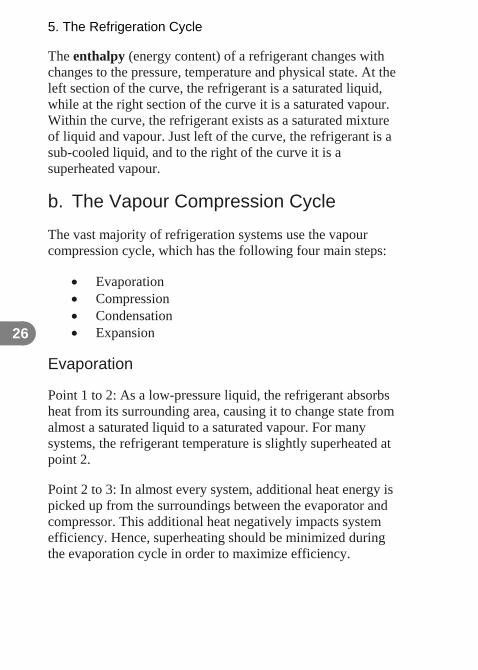
The enthalpy (energy content) of a refrigerant changes with changes to the pressure, temperature and physical state. At the left section of the curve, the refrigerant is a saturated liquid, while at the right section of the curve it is a saturated vapour. Within the curve, the refrigerant exists as a saturated mixture of liquid and vapour. Just left of the curve, the refrigerant is a sub-cooled liquid, and to the right of the curve it is a superheated vapour.
b. The Vapour Compression Cycle
The vast majority of refrigeration systems use the vapour compression cycle, which has the following four main steps:
Evaporation Compression Condensation Expansion
Evaporation
Point 1 to 2: As a low-pressure liquid, the refrigerant absorbs heat from its surrounding area, causing it to change state from almost a saturated liquid to a saturated vapour. For many systems, the refrigerant temperature is slightly superheated at point 2.
Point 2 to 3: In almost every system, additional heat energy is picked up from the surroundings between the evaporator and compressor. This additional heat negatively impacts system efficiency. Hence, superheating should be minimized during the evaporation cycle in order to maximize efficiency.

5. The Refrigeration Cycle
27
Compression
Point 3 to 4: The compressor takes the superheated vapour and raises its pressure. This results in a large temperature increase as some of the compression energy is transferred into the refrigerant causing additional superheating.
Condensation
Point 4 to 5: The hot refrigerant vapour emits a small amount of heat to the surroundings between the compressor and condenser, which is good for system efficiency.
Point 5 to 6: High-pressure superheated refrigerant flows into the condenser where it is first de-superheated (Point 5 to 5a) and then converted into a saturated liquid (Point 5a to 6). Cooling for the condenser is normally accomplished by using water-cooled or air-cooled heat exchangers.
Point 6 to 7: Additional reductions in temperature results in sub-cooling, and this is generally good for energy efficiency.
Expansion
Point 7 to 1: The high-pressure sub-cooled liquid refrigerant passes through an expansion device. Consequently the pressure is reduced, which results in the refrigerant temperature also decreasing.

5. The Refrigeration Cycle
c. Key Steps of Vapour Compression Refrigeration
The primary refrigeration system components are illustrated in Figure 4, and a short explanation of the process between points follows.
Figure 4 Simplified Refrigeration System Components
(Graphic Courtesy UK Carbon Trust) 28
1 to 2: The refrigerant absorbs heat in the evaporator. The source of heat can be anything or everything that surrounds the evaporator.
2 to 3: A small amount of additional heat is absorbed by the refrigerant in the suction line. This additional superheating should be minimized by adding insulation to the refrigerant line.
3 to 4: The compressor compresses the refrigerant vapour from low to high pressure. In doing so, the refrigerant vapour heats up.

5. The Refrigeration Cycle
29
4 to 5: A small amount of heat is lost to the ambient air at the discharge line. This heat loss should be maximized for optimal efficiency.
5 to 6: Heat is released in the condenser as the refrigerant changes state from a superheated vapour into a liquid at high pressure. The heat energy that is released is picked up by ambient air or by cooling water.
6 to 7: Liquid refrigerant flowing from the condenser to the expansion device usually discharges heat to ambient air. As this does not consume additional power, it benefits system capacity and efficiency.
7 to 1: The pressure drop between the condenser and evaporator is maintained using an expansion device. During this process, the saturation temperature of the refrigerant also reduces as the pressure drops.
d. Component Performance
Evaporator
The cooling ability for an evaporator is dependent on the temperature difference between the medium being cooled and the evaporating refrigerant. As the temperature difference increases between the two, the rate of heat transfer also increases. The design and size of the evaporator also influence its efficiency.
Compressor
Compressor performance is influenced by the compressor displacement, which is the volume of refrigerant moved over a period of time (m3/s). It also depends on the temperature lift,

5. The Refrigeration Cycle
30
which is the difference between the condensation and evaporation temperatures. Compressor performance is also influenced by refrigerant properties, as well as the temperature of the superheated suction vapour.
e. Coefficient of System Performance
It stands to reason that the smaller the refrigeration load, the lower the power consumption. Refrigeration load can be lowered by minimizing or eliminating heat gains through the following means:
Walls, ceilings and floors of enclosed rooms or cabinets
Air changes through doors or open cabinets Heat produced from interior lights, fans, motors or
other devices Heat from people or motive equipment used within the
refrigerated space
f. Measurement of Efficiency
Coefficient of Performance (COP) and Coefficient of System Performance (COSP) are two measures used for refrigeration efficiency. COSP is more commonly used as it takes into account all ancillary loads (e.g. fan motors and pumps), as well as the controls that are associated with the system. COP does not take these loads into consideration and considers only the performance of the core refrigeration system.
COSP is the refrigeration capacity (kW) divided by the operating input power (kW).

5. The Refrigeration Cycle
31
Theoretical efficiency for the refrigeration cycle is defined as the heat extracted divided by the work input, or Coefficient of Performance (COP). The mathematical calculation normally involves using the Kelvin scale. Absolute zero temperature is 0°K or -273.15°C.
Example
Calculate the theoretical COP for when heat is removed at a temperature of -10°C and discharged at a temperature of 30°C.
-10°C converts to 263 K, and 30°C converts to 303 K.
Ideal COP = 263 / (303 – 263) = 8.8
This ideal COP implies that 8.8 times the input work can be extracted through the refrigeration cycle.
g. Factors Impacting Efficiency
System efficiency varies in proportion to the temperature lift of the refrigeration system.
As the temperature lift is reduced, the refrigeration compressor capacity increases.
As the condensing temperature is lowered, the compressor power input decreases.
As evaporating temperature increases, so too does the compressor power input; however, this power increase is less than the capacity increase.
Temperature lift is reduced when one or both of the following occur:

5. The Refrigeration Cycle
32
The condensing temperature is lowered. The evaporating temperature is raised.
Decreasing the temperature lift by 1°C will improve efficiency and reduce operating costs by 2% to 4%. Temperature lift can be reduced by increasing the evaporator temperature or by decreasing the condenser temperature.

6. Compressors
33
6 COMPRESSORS
The refrigeration compressor’s purpose is to draw low-pressure refrigerant vapour in the evaporator and compress it to the higher pressure required at the condenser.
The two most common types of compressors are positive displacement and dynamic.
Positive displacement types compress discrete volumes of low-pressure gas by physically squeezing the volumes, resulting in a pressure increase.
Dynamic types increase the velocity of the low pressure gas and then reduce it in such a manner so as to result in an increased pressure. Dynamic compressors are found in the very largest refrigeration systems and are not discussed at length in this guide.
a. Positive Displacement Compressors
The three most common types of positive displacement compressors used for refrigeration systems are the following:
Reciprocating Screw Scroll
Reciprocating Compressors
Reciprocating compressors are the most widespread type used. Refrigerant vapour from the suction is compressed by pistons moving in a bore. Reciprocating compressors are commonly available in a range of sizes, from a small, single-cylinder type

6. Compressors
34
used in domestic refrigerators, to eight-cylinder models used in industrial applications.
There are many types of capacity control with reciprocating compressors, ranging from blocking the suction vapour line, to recirculating the discharged vapour from the piston to the suction vapour. The latter method is the least efficient, in that the power input to the compressor is usually the same in part load as it is in full load.
Screw Compressors
The screw compressor sweeps a volume through two rotors that are meshed together. As the rotors turn inside the closely fitted casing, the space becomes sealed and the gas is compressed. Maintenance, adequate lubrication, cooling and sealing between the working parts is very important. Screw compressors do not have clearance volume, and there is no loss of volumetric efficiency from re-expansion, as in a piston machine. Leakage of refrigerant back to the suction via in-built clearances is a main cause of reduced volumetric efficiency.
Capacity reduction for screw compressors can be effected by a sliding block covering part of the barrel wall. This permits gas to pass back to the suction, causing a variance to the working stroke. Figure 5 shows a typical actual and ideal capacity control curve for a screw compressor.

6. Compressors
Full load
power (%)
Actual
Ideal
Capacity (%)
35
Figure 5 Screw Compressor Capacity Control
Scroll Compressors
Scroll compressors are positive displacement machines that compress refrigerants with two inter-fitting, spiral-shaped scroll members. One scroll remains fixed while the other scroll moves in orbit inside it.
The scroll has certain common features with the screw compressor. Scroll compressors typically have a very low leakage and heat transfer loss.
Scroll compressors also have flat volumetric curves which enable them to deliver more cooling and heating capacity at extreme conditions.

6. Compressors
36
Capacity control using variable speed inverter drive is possible for many scrolls.
b. Compressor Efficiency
The amount of gas pumped by the compressor is always less than the physical displacement of the pistons in the cylinders. Volumetric efficiency (VE) generally includes all the losses affecting the flow rate of the compressor.
The energy efficiency of compression is defined with reference to the ideal adiabatic compression process.
The type and size of a compressor can influence the refrigeration system’s performance. Moreover, many compressors need ancillary devices such as cooling fans, which also consume power. In making a purchase selection, it is important to factor in the energy consumption of all associated equipment.
It is often advantageous to divide up the load between smaller compressors for large loads. Operationally, this is accomplished using control systems which match the overall compressor capacity to the refrigeration load requirements. In cases where the compressors are uneven in terms of size, vintage, or manufacturer, control systems play an important role. Keep in mind that frequent starting of compressors can reduce both equipment life and reliability.
System optimization can benefit from the following:
Using multiple smaller compressors rather than a single, large compressor.

6. Compressors
37
Selecting a combination of different compressor sizes, which allows the control system to mix and match for the best refrigeration operation and performance.
Using control systems and strategies to minimize part-load operation. It is inevitably better to operate one compressor at 100%, as opposed to running two compressors at 50% each.

6. Compressors
38

7. Evaporators, Condensers and Expansion Valves
39
7 EVAPORATORS, CONDENSERS AND EXPANSION VALVES
a. Evaporator Efficiency
For optimal evaporator efficiency, the evaporating temperature should be as high as possible. Oil should not be allowed to build up within the evaporator, and the tubes in a shell and tube evaporator should be cleaned regularly so as to prevent corrosion and fouling. Moreover, refrigerant flow through the evaporator should be correctly controlled to make full use of its capacity with minimum amount of superheat.
b. Defrosting Evaporators
The buildup of ice on the evaporator decreases overall system efficiency when temperatures fall below 0°C. The three most common ways to manage or remove the ice are the following:
Electric Defrosting: This method periodically switches on electric defrost heaters that are embedded in the fin block. Keep in mind that this adds to system electricity consumption.
Natural Defrosting: If the ambient air temperature is above 4°C, it can be circulated over the defrost block, using fans.
Hot Gas Defrosting: Hot discharge vapour is circulated through the evaporator to melt the ice.

7. Evaporators, Condensers and Expansion Valves
40
c. Energy Efficiency and Defrosting
Several factors are at play in regenerating energy efficiency of the defrosting process, including:
Applying the necessary defrost heat in the most effective manner.
Commencing a defrost operation following any measurable loss of performance.
Distributing the defrost heat evenly over the entire fin block.
Halting the defrost cycle as soon as the fin block is free of ice.
Keeping the evaporator temperature as high as possible.
Minimizing the fluid or refrigerated product’s ability to absorb defrost heat.
Minimizing the level of humidity near the evaporator. Utilizing sensors and other instrumentation for
“defrost on demand”.
d. Condenser Efficiency
The three most common types of condensers employed in refrigeration systems all have associated levels of energy consumption:
Air-cooled: requires fan power. Water-cooled: requires a circulating pump power and
usually a cooling tower. Evaporative: requires fan and pump power.

7. Evaporators, Condensers and Expansion Valves
41
Lowering the condensing temperature generally results in lower overall energy consumption. Condensing temperature can be lowered by improving the heat transfer capability, which includes the following:
Keeping air-cooled condenser fin blocks free of debris.
Not using water-cooled condenser tubes that are fouled, corroded or scaled.
Keeping air and other non-condensables out of the system.
Allowing the condensing pressure to float with ambient temperature to take advantage of the lower ambient temperatures overnight and during winter.
e. Expansion Devices
Expansion devices are designed to reduce the pressure of the liquid refrigerant to allow evaporation to occur. There are four types of expansion device widely used in commercial and industrial refrigeration:
Capillary tubes and orifice plates Thermostatic, electronic or balanced port expansion
valves Float valves (high and low side) Hand expansion valve and level switch
For improved energy efficiency, expansion devices should be clean and free of debris.

7. Evaporators, Condensers and Expansion Valves
42 g. Enclosed Motors
f. Capacity Control
Refrigeration systems are designed to have a maximum duty to balance a calculated maximum load. For most of its operational life, the system may work at some lower load level. Capacity control can be achieved by many means.
Speed control is the most obvious method, but this requires an inverter drive. Rotational speed can be reduced by two-speed electric motors or by use of a variable speed drive to control the motor speed. The lowest permitted speed is generally dictated by the in-built lubrication system.
Multi-cylinder machines permit reduction of the working swept volume by removing cylinders from service with blocked suction or valve-lifting mechanisms.
The vast majority of compressors in the market incorporate an enclosed (hermetic) motor. This avoids or greatly reduces any probability of slight leakage of refrigerant through the drive or shaft gland.
The semi-hermetic or accessible-hermetic compressor has the rotor of its drive motor integral with an extended crankshaft, and the stator is fitted within an extension of the crankcase.
Small compressors can be fully hermetic, in that the motor and all working parts are sealed within a shell. Because of the seal, however, they are not very accessible for servicing. Hermetic compressors are commonly found in domestic refrigerators, freezers and other white goods appliances. The upper size limit

7. Evaporators, Condensers and Expansion Valves
43
of the hermetic compressor is determined by production and manufacturing methods.
DC motors are also used in some small compressors, and a converter is required to convert the supply from the AC source. In a global market, one advantage of this approach is that only one DC motor is required for each model despite multiple international AC supply voltages. Moreover, the DC motor is universal and additionally provides variable speed capability.
h. Compressor Lubricating Oil
Lubricating oils from the compressor flow through the refrigeration circuit with the refrigerant. It is vital that this oil returns to the compressor, but in some cases, it can end up in the evaporator. Oil coating the heat exchanger tubes within the evaporator negatively impacts heat transfer and overall system efficiency.

7. Evaporators, Condensers and Expansion Valves
44

8. Refrigerants
45
8 REFRIGERANTS
A refrigerant is the chemical compound or mixture that physically transfers heat within the refrigeration circuit.
a. Refrigerant Characteristics
Although no single refrigerant possesses all of the ideal desired properties, in selecting a refrigerant, the following characteristics would be desirable:
Chemically stable, compatible with construction materials
Critical temperature and triple point well outside the working range
Environmentally friendly High latent heat of vaporization High suction gas density Low cost Miscible with lubricants Non-corrosive, non-toxic and non-flammable
In response to environmental issues, there have been significant changes in the use and selection of refrigerants during the last 25 years. Prior to that, chlorofluorocarbon (CFC) refrigerants had dominated the market since their invention in the 1930s. CFC refrigerants had many desirable properties; they were non-toxic and non-flammable, and had good thermodynamic properties and oil miscibility characteristics. The CFCs R12, R11, R114 and R502, together with hydrochlorofluorocarbon (HCFC) R22, became the dominant refrigerants for most commercial, residential and air-conditioning sectors. Ammonia (R717) also has excellent

8. Refrigerants
46
thermodynamic properties. With its lower cost compared to CFCs, ammonia became the workhorse refrigerant for larger industrial applications.
Environmental concerns have resulted in the development of replacements for the chlorine-containing refrigerants.
b. Ozone Depletion Potential
The earth’s ozone layer filters most of the ultraviolet radiation from the sun, which can be harmful to health. There were serious concerns that the ozone layer was thinning, in large part due to CFC emissions. The ozone depletion potential (ODP) of a refrigerant represents its effect on atmospheric ozone, and the CFC R11 is assigned an ODP index of 1.
The Montreal Protocol on Substances that Deplete the Ozone Layer was signed in 1987. The refrigeration industry rapidly moved from CFCs to HCFC blends. At subsequent revisions of the Protocol, a phase-out schedule for HCFCs was also established. R22, an HCFC, has a far lower ODP than the CFCs; under the Protocol, it, together with other HCFCs, will be eliminated by 2030.
Chemical companies have since developed a range of hydrofluorocarbons (HFCs) to replace the chlorine-containing CFCs and HCFCs. In general, HFCs have slightly worse thermodynamic properties than R22, and do not exactly match the performance of the refrigerants they are intended to replace.
Although R134a, the first HFC to become commercially available, is a close substitute to R12, other HFC refrigerants now in use contain blends of two or three HFCs.

8. Refrigerants
47
c. Refrigerant Applications
Future developments and environmental considerations could restrict the use of HFCs. The refrigerants R134a and R407C are primarily used for air conditioning and have replaced R22 in many applications.
Since R134a has a relatively low pressure, the compressor displacement needs to be about twice the amount when compared to R22. R134a has been used successfully in screw chillers with short tubing lengths. R134a also has a niche application where extra high condensing temperatures are required.
R407C is a zeotropic mixture consisting of 23% R32, 25% R125 and 52% R134a. It has properties close to those of R22.
R404A is an HFC used mostly for commercial refrigeration. It performs better than other HFCs in low temperature applications and is suitable for single stage compression, thus avoiding the requirement for interstage cooling.
R717, which is ammonia, has a long and proven history as an industrial application refrigerant. It has high toxicity and low flammability. Ammonia cannot be used with copper or copper alloys, so refrigerant piping and components have to be steel or aluminum.
R290, propane and other hydrocarbons like butane are being used in new low-charge systems where CFCs and HCFCs have previously been employed. They have clear flammable characteristics that must be considered. Sealed refrigerant systems, such as domestic refrigeration and unitary air conditioners, are being designed with R290 in mind.

8. Refrigerants
48
R744 or carbon dioxide, which was an early refrigerant, is once again attracting interest, especially in the food and beverage industry. It has physical properties that make it attractive for cooling and refrigeration applications. However, because of its operation at pressures of up to 130 bar, R744 systems require highly resistant components that have already been developed for mass production in many sectors.
Table 4 summarizes common refrigerants with respect to environmental impacts, uses and key considerations.
d. Safety and Health Issues
This guide is not intended to be a comprehensive source of health and safety information regarding refrigeration. However, when dealing with any refrigerant or refrigeration equipment, personal safety and the safety of others are extremely important. Service work should only be performed by qualified personnel. Attention should be paid to the toxicity, flammability and asphyxiation potential of refrigerants. Service and maintenance personnel should be familiar with safety procedures and the necessary steps to follow during an emergency. Procedures established by equipment and refrigerant manufacturers should be followed.

8. Refrigerants
49
Table 4 Common Refrigerants
Typ
e
Exa
mp
les
Ozo
ne
Dep
leti
on
P
ote
nti
al
Glo
bal
W
arm
ing
P
ote
nti
al
Use
s
Oth
er
issu
es
CFC R12 R502 R11
High High Widely used in most applications until 1990
Phased out of production
HCFC R22 R409A R411B
Low High Widely used in many applications after 1999.
To be phased out of production in 2015.
NH3 Ammonia
R717 Zero Very low
Used in industrial and large commercial systems
Toxic and flammable, reacts with copper.
HFC R134a R404A R407C R410C R507
Zero High Started to be used in place of CFCs from about 1990
Different compressor oil required Performance of some HFCs not as good as CFCs.
Hydrocarbon R600a R290 R1270
Zero Low R290 used in some industrial systems for decades.
Flammable,
CO2 Carbon dioxide
R744 Zero Low Widely used before the 1950s
Not in widespread commercial use

8. Refrigerants
50

9. Purchasing a New Refrigeration System
51
9 PURCHASING A NEW REFRIGERATION SYSTEM
Here are some points to keep in mind when purchasing a new refrigeration system.
Over its lifetime, a new refrigeration system will consume electricity valued at several times more than the original capital purchase cost. Hence, it is important to ensure that any new equipment is as efficient as it is practical.
The following are some questions to ask when designing a new refrigeration system:
What type of process or product needs cooling? What is the required level of cooling? How long must the product be cooled for? Where is the best location for the refrigeration
equipment? Are there any foreseeable changes to product or
process refrigeration requirements?
To accompany an energy-efficient refrigeration system, also remember to purchase energy efficient options such as the following:
Low-power lights Energy-efficient fans and motors Defrost-on-demand controls for evaporators Night blinds for food cases Strip curtains for storerooms Larger condensers that are capable of discharging
larger amounts of heat

9. Purchasing a New Refrigeration System
52
It is important to also note that refrigeration requirements often change over time; hence, a one-for-one replacement may not be ideal for energy efficiency.
Lifetime Cost of Ownership
Refrigeration systems typically cost 8 to 10 times as much to operate as they do to purchase. When evaluated on a life cycle basis, there could be a significant variation between refrigeration options from different manufacturers and contractors.
When sourcing refrigeration systems, capital cost and operating costs should be evaluated. Capital costs include the initial cost for the refrigeration system and components. Operating costs include electricity and expected operations and maintenance (O&M) over the anticipated life of the refrigeration equipment. Be sure to account for the power consumed by ancillary equipment like auxiliary fans, pumps and motors.
To evaluate the financial performance, financial calculations should be done to determine the following:
Payback period Net present value (NPV) Return on investment (ROI) Internal rate of return (IRR)
The NPV should always be a positive value, and when two or more of the financial criteria are taken in context, one can make the best decision regarding refrigeration system selection.

10. Industry Specific Refrigeration Efficiency Tips
53
10 INDUSTRY SPECIFIC REFRIGERATION EFFICIENCY TIPS
a. Supermarkets and Food Retail
Electricity consumption in retail supermarkets for refrigeration requirements can cost 20 to 40% of the total electricity bill. There are certain best practices that can be adopted:
Avoid loading a case with product that is above its desired storage temperature.
Clean the appliance regularly for food and packaging debris, especially near the air inlet and outlet.
Consider using night lines on retail display cabinets at nighttime.
Avoid placing the appliance near a heater, oven or other source of heat.
Ensure adequate airflow for condensers. Only fill the case to the load line. Shield the appliance or case from direct sunlight. Thermostats should not be set to a temperature lower
than is required.
b. Manufacturing and Distribution
The plastics and food & beverage industries are prime manufacturing sectors where refrigeration is used. The following best practices should be observed:
Use door strips and air locks to minimize heat gain. Maintain door seals in good operating condition.

10. Industry Specific Refrigeration Efficiency Tips
54
When loading product, avoid blocking airflow. Avoid loading warm product in a refrigerated zone. Thermostat set points should not be lower than
necessary.
Packaged Water Chillers
Packaged water chillers are generally used for space or process cooling. These units are generally sold as complete systems that are mounted on a single frame. They typically chill water to approximately 5°C, and in the case of space cooling, the chilled water passes through a fan coil unit.
For process-related requirements, the chilled water is conditioned to approximately 0.5°C and is applied to a specific process, such as cooling milk following pasteurization.
Additional energy savings can be realized by proper sizing of compressors, appropriate control points, and variable speed water pumping to match the required loads.

11. Instrumentation
55
11 INSTRUMENTATION
Most refrigeration systems should be commissioned when first installed or when a significant equipment overhaul is completed.
In order to complete the commissioning, appropriate instrumentation will be required. In some cases, refrigeration equipment is pre-packaged with commissioning and monitoring instrumentation.
Most refrigeration manufacturers, contractors and service providers can advise on site-specific instrumentation requirements.
For a refrigeration tune-up or commissioning, the following measurements can be considered as the absolute minimum to be taken and recorded:
Ambient conditions Dry and wet bulb Refrigerant pressures and temperatures at:
o Expansion valve inlet o Evaporator outlet o Compressor suction o Compressor discharge
Secondary fluid temperatures at heat exchanger inlets and outlets
Pump, fan and filter pressures Settings of all adjustable controls Electric motor amps

11. Instrumentation
56
12. Low-Cost No-Cost Refrigeration Improvements
57
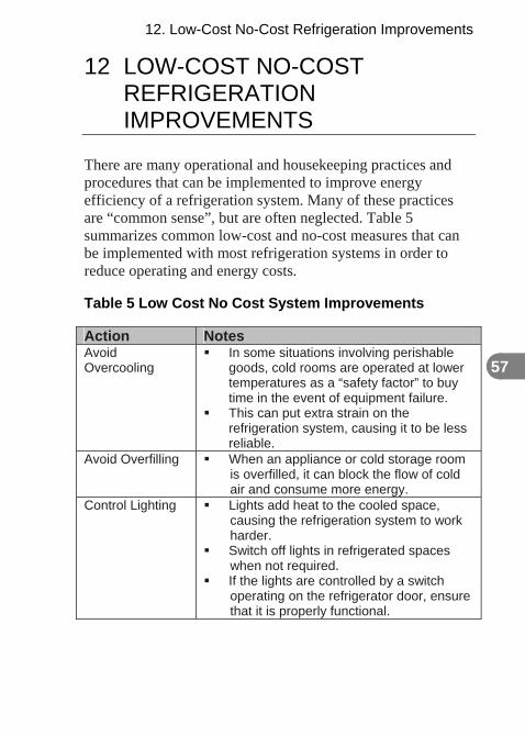
12 LOW-COST NO-COST REFRIGERATION IMPROVEMENTS
There are many operational and housekeeping practices and procedures that can be implemented to improve energy efficiency of a refrigeration system. Many of these practices are “common sense”, but are often neglected. Table 5 summarizes common low-cost and no-cost measures that can be implemented with most refrigeration systems in order to reduce operating and energy costs.
Table 5 Low Cost No Cost System Improvements
Action Notes Avoid Overcooling
In some situations involving perishable goods, cold rooms are operated at lower temperatures as a “safety factor” to buy time in the event of equipment failure.
This can put extra strain on the refrigeration system, causing it to be less reliable.
Avoid Overfilling When an appliance or cold storage room is overfilled, it can block the flow of cold air and consume more energy.
Control Lighting Lights add heat to the cooled space, causing the refrigeration system to work harder.
Switch off lights in refrigerated spaces when not required.
If the lights are controlled by a switch operating on the refrigerator door, ensure that it is properly functional.

12. Low-Cost No-Cost Refrigeration Improvements
58
Action Notes Control the Temperature to the Required Level
Overcooling wastes energy and does not improve the longevity of a food product.
For every 1°C cooler than what is necessary, electricity consumption increases by 2 to 4%.
Ensure Door Seals are Fitting and Functional
Missing or improperly fitted seals allow cold air to escape from the refrigerated zone.
Install Night Blinds
Night blinds are an effective way to retain cold air in display cabinets during store closures.
Minimize Air Change Rate
Air changes, which can amount to 30% of total heat load, can be minimized by ensuring that doors are closed.
Optimize Evaporator Performance
Ice builds up on evaporators that operate below 0°C.
Regular defrosting helps to prevent ice buildup
Reduce Heat Load
Heat gained from ancillary equipment can be minimized by using more efficient fans, motors and lights together with effective control strategies.
Situate the Equipment to Minimize External Heat Gains
Avoid situating refrigeration equipment near heat sources like direct sunlight or radiators.
Ensure that the condenser has adequate ventilation.
a. System Energy Optimization Tips
Refrigeration system components and control points can be used for overall system optimization. Elements include the following:
Use condensers with modestly larger capacity readings than suggested by conventional practice.

12. Low-Cost No-Cost Refrigeration Improvements
59
Allow the condensing temperature to float down with ambient temperature based on season of the year or time of day.
Ensure that condensers are not blocked so that cooling water and or cooling air can flow effectively.
Use a higher-rated or larger evaporator than conventional practice suggests.
Defrost the evaporator periodically when necessary. Choose the best type and size of compressor. This
depends on many factors including cooling load size, type of refrigerant used, and temperature differentials.
Too much or too little refrigerant has a significant impact on temperature lift and system performance. In some cases, systems that are overcharged with refrigerant can consume more power than necessary and also have the potential to lose more during leaks.
Choice of refrigerant can also affect energy efficiency. The most appropriate refrigerant choice is usually dependent on the application and the type of compressor.
Aim to minimize the amount of superheat in the suction vapour. The warmer the vapour becomes, the less the capacity of the compressor. Optimization can generally be achieved by insulating the suction line and correctly controlling the expansion valve.
Maximize the amount of liquid refrigerant sub cooling before it enters the expansion device. This increases system capacity without impacting power consumption.
Monitor control point settings, as these may have drifted from optimum levels since system commissioning.

12. Low-Cost No-Cost Refrigeration Improvements
60

13. Checklist for Operational and Maintenance Improvements
61
13 CHECKLIST FOR OPERATIONAL AND MAINTENANCE IMPROVEMENTS
a. Day-to-Day Operation
Here are some low-cost or no-cost measures that can be implemented to reduce energy consumption in refrigeration systems.
Clean the condenser and evaporator on a regular basis. Defrost the evaporators as necessary. Ensure that correct refrigerant is in use. Ensure that the system is leak-free. Insulate the suction line. Size the condensers and evaporators to allow for the
lowest effective condensing temperature and the highest practical evaporating temperature.
Use high-efficiency motors for the compressor and other fans and pumps.
Where possible, pre-cool any material before placing it into the refrigerated zone.
b. Routine Maintenance Tips
The following practices should be considered for implementation in a routine maintenance program.

13. Checklist for Operational and Maintenance Improvements
62 c. Minimizing Parasitic Loads
Carefully remove scaling and ice buildup on the evaporator. If left to build up, it will hinder heat extraction ability.
Check for excessive noise or vibration from the compressors, as this could indicate worn bearings
Ensure that drip pipes or bleed valves are not iced up. Lubricate and service the compressor regularly, as per
manufacturer specifications. Periodically check compressor oil levels, together
with suction and discharge temperatures and pressures.
Repair damaged pipe insulation. Replace damaged fans promptly. Replace defective gauges.
Undesired strain can be put on a refrigeration system from parasitic loads. In fact, these loads can use energy twice – directly from consuming energy, and indirectly from producing heat gain that must be extracted by the refrigeration system.

13. Checklist for Operational and Maintenance Improvements
63
Table 6 Opportunities to Minimize Parasitic Loads in Refrigeration Systems
Undesired Source of Parasitic Load
Opportunities to Minimize the Parasitic Loads
Air changes Minimize air changes in cold space by using good practices of door management and dehumidification.
Cold room fans & pumps
Use energy efficient fans, pumps and motors
Consider variable speed drives Operate only when required
Heat gains through insulation
Check (and repair) insulation regularly
Lighting Use energy efficient lighting Turn off lights when not required
Machinery in cold spaces
Minimize the use of machinery in the refrigerated space
Personnel Keep occupancy in refrigerated space to minimum

13. Checklist for Operational and Maintenance Improvements
64

14. Diagnosis Methodology for System Optimization
65
14 DIAGNOSIS METHODOLOGY FOR SYSTEM OPTIMIZATION
a. Troubleshooting and Fault Tracing
Refrigeration system faults can be categorized into two general classes:
1. Sudden catastrophe of a mechanical breakdown. 2. Slow fall-off of performance.
Slow fall-off performance can generally be detected as a malfunction at an early stage, and can lead to a breakdown if not corrected early enough. An experienced refrigeration technician will often know where to look and what corrective actions may be appropriate.
Fault tracing is a multistep process of deduction, with the end goals of attaining normal operation and recording the circumstances. Fault tracing includes the following:
Detection of abnormal operation. Applying knowledge of the system to track down the
root cause. Observing the operating conditions. Identifying the fault. Deciding how severe the fault is, and how it can be
rectified. Taking action to repair the fault. Testing the system once repairs are implemented. Recording the cause and solution in the refrigeration
system log.

14. Diagnosis Methodology for System Optimization
66 Refrigerant liquid temperature before the expansion valve
b. Refrigeration Logs and Records
Many refrigeration system operators do not keep adequate or detailed equipment performance logs. Operating logs are important in that they allow for the evaluation of equipment performance and serve as a tool to characterize potential system deficiencies.
The following parameters are suggested as the minimum to be included for simple vapour compression refrigeration system log books:
Inlet air and water temperature of the condenser and evaporator
Suction and discharge pressure of the compressor Refrigerant temperature at the inlet of compressor and
outlet of evaporator
Power input Outlet temperature of the compressor
With all of these measurements, the following relevant parameters for evaluating a compressor can be calculated:
Coefficient of Performance (COP) Refrigeration system capacity Sub-cooling Superheat Compressor efficiency together with evaporator and
condenser temperature differences.

15. Commissioning and Maintenance
67
15 COMMISSIONING AND MAINTENANCE
Commissioning is unfortunately often overlooked, but it is an important step to ensure that refrigeration systems operate reliably and efficiently.
The objective of commissioning is to ensure that the equipment meets with a specified set of conditions for which it was designed.
Commissioning of a refrigeration system typically starts from the stage of equipment placement, and ends with the development of standard operating procedures for startup, operation and shutdown.
Maintenance is the ongoing effort necessary to ensure that a commissioned plant continues to deliver correct performance; it includes inspections designed to indicate signs of deterioration prior to any noticeable effects.
a. Baseline Specification
When specifying the refrigeration system requirements, the owner and the contractor/vendor must address several parameters, including the following:
The process or product to be cooled The location where the product or process will be
located Total required cooling capacity during normal and
extreme conditions Maximum design and normal ambient cooling
temperatures

15. Commissioning and Maintenance
68
Expected power input for the compressor and auxiliaries at the maximum and normal expected conditions
Part load (daily or seasonal) requirements Control boundaries and limits The conditions of the refrigeration system during
normal operation, including condensing, evaporation, superheating and sub-cooling
Use of simplified block flow diagrams to plan for and record refrigeration plant performance
b. Commissioning
The act of commissioning should take place under the direction of a single competent authority—main contractor, a consultant or the user. This authority should have copies of all major equipment ratings and the manufacturer’s instructions or startup guides.
Commissioning Report
The commissioning report should include the following:
Equipment specification listing, including cooling capacity, operating conditions and boundaries
Circuit diagrams for refrigeration and electrical equipment
Refrigerant charge and process conditions Initial set points for the controls and safety devices Commissioning and operating instructions for all
major components Actual site tests performed, such as pressure, system
tightness and electrical tests

15. Commissioning and Maintenance
69
Commissioning Process
The commissioning process involves several steps including the following:
The commissioning process begins by checking that the installed equipment is in accordance with the specified design. This includes a review of piping installation, heat exchanger cleanliness, water circuits and filters, compressor mountings, correct connection of safety and pressure controls, and correct wiring and control sequence.
The next stage is to preset as many controls and protection devices as possible with their intended set points.
Next, in the absence of refrigeration equipment operating, the pump and fan flows should be evaluated using flow meters and pressure differentials.
The refrigerant charge should have been added according to the weight specified for the system.
At this point, the entire system is turned on and left to operate for a shakedown period, which may last from a few hours to several days depending on the nature and complexity of the system.
During the shakedown period, components should be checked for vibrations, leaks or other malfunction.
In the concluding commissioning stage, readings should be recorded and compared with the specification and design figures. o Ambient conditions, including wet and dry bulb
temperatures. o Refrigerant pressures and temperatures at
expansion valve inlet, evaporator outlet, and compressor suction and discharge.

15. Commissioning and Maintenance
70
o All secondary fluid temperatures at heat exchanger inlets and outlets.
o The pressures for pumps, fans and filters. o Electric motor amperage.
Preventative Maintenance
The purpose of preventative or planned maintenance is to ensure that the refrigeration system operates reliably and efficiently. The refrigeration system should remain leak-tight in order to maintain efficient operation and to reduce the incidence of outages.
Preventative maintenance programs have determined that the following points can be the principal causes for system performance deterioration:
Accumulated dirt on air filters increases the resistance and leads to reduced air flow.
Fouling of air or water-cooled condenser raises the condensing temperature and increases compressor power consumption.
Incorrect refrigerant charge can lead to prolonged operation at below-optimal conditions. Refrigerant loss causes a reduction in the wet surface in the evaporator and a reduction in evaporating temperature.
Excessive pressure and temperature fluctuations can be caused by a regular expansion valve operation or adjustment.

16. Refrigeration Performance Measurements
71
16 REFRIGERATION PERFORMANCE MEASUREMENTS
Depending on the resources available in the complexity of the refrigeration system, there can be two strategies implemented to measure the performance of a refrigeration system.
Strategy One – Indirect Diagnostic
This is the simpler of the two strategies. It involves close examination of specific components (e.g. evaporators) and inference of a specific fault or incorrect operating strategy. Using this method, one would take an instantaneous measurement or observation of the specific parameter and compare it to an expected value or consequence at some point in the refrigeration system. By understanding the relationship between cause and effect, one can diagnose or zero in on a specific equipment or set point efficiency in the system. Corrective action may be then taken accordingly to eliminate the energy inefficient equipment or operating practice. Figure 6 illustrates the common placement points for temperature and pressure measurement instrumentation.

16. Refrigeration Performance Measurements
72
Symbol Parameter Comments TEin and TEout
Cooling load temperatures
Process stream temperatures at inlet and exit of the evaporator.
TCin and TCout
Heat rejection temperatures
Fluid temperatures at inlet and exit of the condenser (air or cooling water).
Tamb Ambient temperature
Dry bulb for air-cooled condensers, wet bulb for evaporative or water cooled condensers.
Ps and Pd Ts and Td
Compressor suction and discharge pressures and temperatures
Gauge pressures at compressor suction and discharge. Actual refrigerant vapour temperature at same locations.

16. Refrigeration Performance Measurements
73
Tliq Liquid temperature of refrigerant leaving condenser
Temperature of liquid in liquid line, after the condenser and receiver but before the expansion valve.
L% Plant load Measured in terms of compressor loading.
PowC and PowA
Power or Amps The power being absorbed by compressor/s and main auxiliaries.
Figure 6 – Suggested Points for Indirect Performance Measurement
By far, the most critical measurements for isolating and diagnosing potential faults are the pressure gauges.
In order for this method to be successful, it is important to have access to plant commissioning data or recently audited performance data, as this will serve for the reference case. This strategy can be completed on an as-required basis, and it provides a snapshot of actual conditions.
Strategy Two – Direct Diagnostic
The second approach builds upon strategy one and is performed over a longer period of time. In addition, this strategy requires more investment in instrumentation, and time to record and analyze data. This method requires that electricity sub-metering equipment be installed, and that it tracks refrigeration performance over a longer period of time. The strategy calls for more time commitment and is often part of an ongoing energy management and performance optimization program. It allows for positive proof that the performance deviation is occurring in the refrigeration system, and it also helps to quantify and justify corrective actions. Moreover, once the corrective actions have been implemented,

16. Refrigeration Performance Measurements
74
this strategy can be used to measure the effectiveness of such changes.
In order for the direct diagnostic method to be effectively used, the refrigeration system should be operating in a steady state mode. With a direct diagnostic method, kWh meters are normally used. Energy consumption for the compressor is measured, and a separate measurement is taken for auxiliary equipment. In some cases, the auxiliary equipment operates at a constant level regardless of the refrigeration system output. Some practitioners prefer to add the energy consumption for the refrigeration equipment itself with the auxiliaries.
The direct diagnostic method uses long-term measurements and can typically be done on a weekly basis for most food and beverage, plastics and other small commercial operations.
For longer-term trends, one can identify approximately a point at which an increase or decrease in system performance occurred. Through further investigation, one can uncover planned or unplanned changes that were made and the consequential impact on COP.
a. Cause and Effect - Symptoms to Look For
Condensers
Is the compressor discharge pressure too high? This may indicate that the condenser or heat exchanger might not be functioning or controlled correctly.

16. Refrigeration Performance Measurements
75
Evaporator
Is the compressor suction pressure too low? The lower the suction pressure, the lower the system efficiency. Moreover, as suction pressure is lowered, the amount of available cooling also decreases.
Compressor
Compressor faults are generally more challenging to detect. In some cases, compressor problems are related to mechanical issues within the compressor that cause undesired blockages that lead to pressure drops.
Expansion Valve
When the expansion valve is open too much, it can lead to an undesired bypass of high-pressure vapour through the valve. The opposite is true in that, when the valve is closed too much, the evaporator is starved of liquid refrigerant.
Control Systems
There can be multiple faults associated with control systems, and it is important to always check settings and control points.

16. Refrigeration Performance Measurements
76

17. Refrigeration Audit Assessment Worksheet
77
17 REFRIGERATION AUDIT ASSESSMENT WORKSHEET
The refrigeration inspection measures and checklists in this chapter were adapted from the CIPEC Energy Efficiency Planning and Management Guide. The checklists are divided into Housekeeping Measures and Low Cost Measures. The checklists can be adapted to a variety of refrigeration plant situations.

17. Refrigeration Audit Assessment Worksheet
78
a. Housekeeping Measures
Action What to Look For
Action if Yes
Action if No
Check heat-transfer surfaces (e.g. evaporators and condensers).
Are tubes and surfaces clean?
Check periodically to maintain standard, more frequently if the operating environment is not clean.
Clean surfaces; schedule regular cleaning.
Check insulation on refrigerant piping and exterior of evaporators.
Is insulation adequate, dry and intact?
Check every six months to maintain standard.
Repair or replace damaged insulation; if necessary, add more insulation to reduce heat gain.
Check thermostat settings.
Are settings correct?
Calibrate thermostats every six months.
Set the thermostat to the highest acceptable operating temperature. Calibrate every six months.
Check refrigerant charge.
Is refrigerant charge correct?
Check regularly to maintain standard.
Add or remove refrigerant. Recheck periodically.

17. Refrigeration Audit Assessment Worksheet
79
Action What to Look For
Action if Yes
Action if No
Check air movement around condensing units and cooling towers.
Is airflow around the condenser restricted?
Remove restriction or relocate condenser. Follow manufacturer’s recommendations.
No action required.
Check operation of heating and cooling systems.
Do heating and cooling systems operate simultaneously in the same area?
Relocate thermostat, isolate process.
No action required.

17. Refrigeration Audit Assessment Worksheet
80
b. Low-Cost Measures
Action What to Look For
Action if Yes
Action if No
Investigate possibility of de-superheating.
Can de-superheating be used to reduce condensing pressures?
Implement the most cost-effective method.
No action required.
Investigate possibility of using floating head pressure.
Can head pressure be reduced without adversely affecting the system?
Determine the lowest pressure that can be used, and reset accordingly.
Investigate limiting factors. Consider using refrigerant liquid pressure booster pumps to overcome line pressure losses and thermal expansion valve pressure drop.
Examine location of outdoor condenser coil.
Is there a cool air exhaust opening?
Consider moving condenser coil into cool air stream.
No action required.
Review evaporator temperature.
Can evaporator temperature be increased without adversely affecting the process?
Reset evaporator temperature as high as possible.
No action required.

17. Refrigeration Audit Assessment Worksheet
81
Action What to
Look For Action if Yes
Action if No
Review cooling loads.
Does system operate at part load for part of the day?
Install automatic controls to provide flexibility and to use higher evaporator temperatures during part-load conditions.
No action required.
Review production cycle.
Can the production cycle be rescheduled to off-peak hours?
Change schedule to run the system during off-peak hours.
No action required.

17. Refrigeration Audit Assessment Worksheet
82

Appendix A – System Assessment Memory Jogger
83
APPENDIX A –SYSTEM ASSESSMENT MEMORY JOGGER
Calibrate and adjust controls for actual load and ambient conditions.
Commission system, and keep operating records. Consider thermal storage. Install heat recovery equipment. Match the size of principal refrigerant components. Maximize system effectiveness for operating load and
ambient conditions. Minimize cooling loads. Monitor system operations periodically. Optimize running conditions. Source and install components based on lifetime
operating costs. Use the correct refrigerant.

Appendix A – System Assessment Memory Jogger
84

Appendix B – Refrigeration Codes and Standards
85
APPENDIX B – REFRIGERATION CODES AND STANDARDS
Depending on the type of refrigeration equipment and the location involved, several national and international standards may apply. For reference, listed below are some of the more pervasive standards.
Canadian Standards Association (CSA) http://www.csa.ca
B52-05, Mechanical Refrigeration Code CAN/CSA-C22.2 NO. 120-M91 (R2008)
Refrigeration Equipment CAN/CSA-C827-98 (R2008) Energy Performance
Standard for Food Service Refrigerators and Freezers C22.2 NO. 140.3-M1987 (R2004) Refrigerant-
Containing Components for Use in Electrical Equipment
CAN/CSA-C657-04 Energy Performance Standard for Refrigerated Display Cabinets (Merchandisers)
International Organization for Standardization (ISO) http://www.iso.org
TC 86/SC 1 Safety and environmental requirements for refrigerating systems
TC 86/SC 2 Terms and definitions TC 86/SC 3 Testing and rating of factory-made
refrigeration systems (excluding systems covered by ISO/TC 86/ SC 5, SC 6 and SC 7)

Appendix B – Refrigeration Codes and Standards
86
TC 86/SC 4 Testing and rating of refrigerant compressors
TC 86/SC 6 Factory-made air-cooled air-conditioning and air-to-air heat pump units
TC 86/SC 7 Testing and rating of commercial refrigerated display cabinets
TC 86/SC 8 Refrigerants and refrigeration lubricants
Air-Conditioning, Heating, and Refrigeration Institute (AHRI) http://www.ahrinet.org
AHRI 420-2008: Performance Rating of Forced-Circulation Free-Delivery Unit Coolers for Refrigeration
AHRI 1110-2006: Performance Rating of Mechanical Transport Refrigeration Units
AHRI 1120-2007: Acoustical Test Methods and Sound Power Rating Procedures for Transport Refrigeration Equipment
ANSI/AHRI 1140-2006: Sound Quality Evaluation Procedures For Air-Conditioning and Refrigeration Equipment
ARI 130-1988: Graphic Electrical/Electronic Symbols for Air-Conditioning and Refrigeration Equipment
American Society for Testing and Materials (ASTM) http://www.astm.org/
E479-91(2006) Standard Guide for Preparation of a Leak Testing Specification

Appendix B – Refrigeration Codes and Standards
87
F2520-05 Standard Specification for Reach-in Refrigerators, Freezers, Combination Refrigerator/Freezers, and Thaw Cabinets
F2143-04 Standard Test Method for Performance of Refrigerated Buffet and Preparation Tables
F2432-04 Standard Specification for Ice-Making Machines, Icemaker-Dispensers, and Ice Dispensing Equipment
F2442-07 Standard Guide for Layout of Ice Arena

Appendix B – Refrigeration Codes and Standards
88

Appendix C – Conversion Factors
89
APPENDIX C – CONVERSION FACTORS
Area 1 in2 = 645.2mm2 1 ft2 = 0.0929 m2
Density 1 lb/ft3 = 16.02 kg/m3
Gravitational Constant
32.2 feet per second per second 9.81 meters per second per second
Length 1 in = 25.4 mm 1 ft = 0.3048 m
Mass 1 oz. = 28.35 g 1 lb = 0.4536 kg
Power 1 hp = 0.7457 kW
Pressure 1 in W.G. = 0.2484 kPa W.G. @ 68°F 1 in Hg = 3.386 kPa, Hg @ 32°F 1 psi = 6.895 kPa 1 kPa = 1000 N/m2 1 atm = 14.696 psi 1 bar = 14.504 psi 1 in Hg = 13.63 in W.G.
Temperature 1 °F = 0.556 °C 0 °C Corresponds to 32 °F, 273.15 K and 491.7 R For °F to °C : TC = (TF - 32) × .556 For °F to °R : TR = TF + 459.7 For °C to °K : TK = TC + 273.2

Appendix C – Conversion Factors
90
Velocity 1 fpm = 5.08 × 10⁻³ m/s 1 ft/s = 0.3048 m/s
Volume Flow 1 CFM = 0.4719 × 10⁻³ m3/s 1 Imperial GPM = 0.2728 m3/hr = 4.546 L/min 1 US GPM = 0.2271 m3/hr = 3.785 L/min
Volume 1 ft3 = 0.02832 m3 1 Imperial Gallon = 4.546 L 1 US Gallon = 3.785 L 1 L = 1 × 10⁻³ m3 1 US Gallon = 0.13368 ft3 1 Imperial Gallon = 1.20095 US Gallon

Appendix D –Glossary of Common Refrigeration Terms
91
APPENDIX D – GLOSSARY OF COMMON REFRIGERATION TERMS
Term Definition Air curtain A steady stream of air (generated by a fan)
that acts as a barrier to separate environments at different temperatures, without blocking the movement of people or objects. Air curtains are used in open-fronted refrigerated display cabinets to retain chilled air within the cabinet’s volume while still allowing ready access to the stored products.
Ambient temperature
The temperature of the outside air.
Ancillary load Load created by secondary equipment. In the case of refrigeration, this may be the additional heat created by lighting or evaporator fan motors in refrigerated space.
Automated leak detection
System that continually monitors for the presence of airborne refrigerant gases and generates an alarm when excessive levels are detected, indicating leakage of refrigerants from the refrigeration system.
Auxiliary energy
Energy used by devices in a refrigeration system other than the main compressors; usually, this refers to pumps and fans.
CFC Chlorofluorocarbon. This is a type of refrigerant consisting of chlorine, fluorine and carbon.

Appendix D –Glossary of Common Refrigeration Terms
92
Coefficient of Performance (COP)
A way of expressing the efficiency of a refrigeration plant. Defined as cooling carried out divided by energy input. Compressor suction and discharge pressures. The pressure at the inlet and outlet of a refrigeration compressor.
Compressor A machine which raises the pressure of a gas, such as a refrigerant vapour. This will usually raise the temperature and energy level of the gas.
Condenser A heat exchanger in which a gas, such as a refrigerant vapour, cools and then condenses to liquid form.
Cooling load The total amount of cooling carried out by a refrigeration plant – usually made up of several individual heat loads.
Defrost-on-demand control
A control system that automatically initiates a defrost sequence when an appropriate amount of ice has built up on the evaporator surface.
Discharge The high pressure exit from a compressor.. Evaporator A heat exchanger in which a liquid refrigerant
absorbs energy from its surroundings and vapourizes, producing a cooling effect.
Expansion valve
A valve through which liquid refrigerant passes and is reduced in pressure and temperature.
Flash The process of liquid refrigerant being vaporized by a sudden reduction of pressure.
Halocarbons A family of primary refrigerants based on hydrocarbon molecules in which some or all of the hydrogen has been replaced by either fluorine or chlorine. Halocarbons include CFCs, HCFCs and HFCs
HCFC Hydrochlorofluorocarbon. A primary refrigerant of the halocarbon family.
Heat exchanger
A device for transferring heat between two physically separate streams.

Appendix D –Glossary of Common Refrigeration Terms
93
Heat of compression
The amount of heat added to the refrigerant vapour by the compressor during the process of raising the pressure of the refrigerant to condenser conditions.
Heat rejection temperatures
The temperature at which a refrigeration plant rejects heat from the condenser, usually into ambient air or cooling water.
Helical-rotary compressor
A type of compressor that uses two mated rotors to trap the refrigerant vapour and compress it by gradually shrinking the volume of the refrigerant.
Hermetic compressor
A type of compressor that has the motor sealed within the compressor housing. The motor is cooled by refrigerant.
Hot gas bypass
A method used to prevent evaporator freeze-up by diverting hot, high-pressure refrigerant vapour from the discharge line to the low-pressure side of the refrigeration system.
Liquid line A pipe that transports refrigerant vapour from the condenser to the evaporator in a mechanical refrigeration system.
Positive-displacement
A class of compressors that works on the principle of trapping the refrigerant vapour and compressing it by gradually shrinking the volume of the refrigerant.
Pressure–enthalpy chart
A graphical representation of the properties of a refrigerant, plotting refrigerant pressure versus enthalpy.
Receiver A vessel used to store a fluid (liquid or gas) usually at pressure. In a refrigeration system, the most common are high-pressure receivers, located after the condenser. Some systems also utilize a low-pressure receiver located before the compressor suction.
Reciprocating compressor
A type of refrigeration compressor using a piston to compress vapour trapped in a cylinder.

Appendix D –Glossary of Common Refrigeration Terms
94
Refrigerant The working fluid of the refrigeration system which absorbs heat in the evaporator and rejects it in the condenser.
Refrigerant leakage
Most types of refrigeration system are prone to some degree of refrigerant leakage. This can cause a loss of cooling performance, excessive energy consumption and damage to the environment.
Screw compressor
A type of refrigeration compressor using a rotating screw to trap a volume of vapour and compress it.
Suction The entry point for vapour into a compressor. Suction strainer
A strainer at the inlet of a compressor designed to prevent damage caused by small objects entering the compressor.
Superheat A thermodynamic term referring to a vapour at a temperature above the boiling point at the prevailing pressure.
Vapour compression cycle
A type of refrigeration cycle using a compressor to remove low-pressure vapour from an evaporator, where it has absorbed heat, and deliver it to a condenser at a higher pressure.
Water cooled condenser
A heat exchanger used to condense refrigerant vapour using cooling water.

Appendix E – Key Sector System Efficiency Opportunities
95
APPENDIX E – KEY SECTOR SYSTEM EFFICIENCY OPPORTUNITIES
a. Ice Rinks
Note: Although the primary focus of this guide is on non-ammonia-based refrigeration systems, the following energy efficiency opportunities are presented for ice rinks, which use ammonia-based refrigeration predominately. The opportunities were adapted from documents published by Manitoba Hydro.
Reductions in radiated heat loads, convective heat loads (rink temperature and humidity), brine pump work, and ice resurfacing have the greatest impact as they constitute the largest energy components for the refrigeration plant. Proper control of ice and ice thickness are key elements.
For most heated rinks, the radiant loads combined with rink temperature and humidity account for almost two-thirds of the total heat gain load on the refrigeration system.
Water purity is critical for the quality of ice produced. Ions and dissolved salts lower the natural freezing point and require more refrigeration to freeze.
From an energy efficiency perspective, keep the temperature of the ice surface as high as possible. Hockey rinks run with 16°F (-9°C) brine returning at 18°F (-8°C). Curling and figure skating ice runs with 22°F (-6°C) brine returning at 24°F (-4°C). Each degree Fahrenheit that the ice temperature can be raised reduces the load on the ice plant by up to 2%.

Appendix E – Key Sector System Efficiency Opportunities
96
Brine at a specific gravity of 1.20 to 1.22 usually results in optimum energy use.
When the compressor is bringing the temperature of the ice down again, from 25°F to 18°F (-4°C to -8°C), keep the number of lights on and other pieces of equipment operating to an absolute minimum to avoid setting a new peak demand.
Other energy efficiency measures include:
Desiccant Dehumidification: Humidity causes the compressors to run longer. Desiccant dehumidification generally uses less energy than compressors, which are not required to overcome the refrigeration load caused by humidity.
Low E Ceiling: A proven method of saving energy is to use Low E (emissivity) ceilings. The ceiling material reduces heat radiation on the ice surface.
Heat Recovery Systems: Heat is a “waste” product for all compressors. Hot gas from the compressor discharge can be diverted to a heat exchanger for functions like space heating, melting the snow pit, ice resurfacing water tank, and domestic water supply.
Caulking and weather-stripping the building shell. Consideration of brine pump cycling or 2-speed
pumping. Installation of timers on ventilation equipment. Keeping the ice thin, ideally 1 in. (25 mm) thick. Matching lighting levels to facility use. Reducing flood water temperatures to 130°F (54°C). Use low emissivity (low E) ceilings.

Appendix E – Key Sector System Efficiency Opportunities
97
b. Supermarkets and Food & Beverage Sectors
Supermarkets are very energy intensive and may have an average specific energy consumption of 1,000 kWh/m2/yr. Conventional refrigeration equipment can account for about half of this energy consumption and often requires large refrigerant charges: 1000 to 2500 kg of HCFC or HFC per store. Secondary loop refrigeration technology systems for supermarkets have been developed and are supported by Natural Resources Canada. Secondary fluid loops are used on freezing and refrigeration (evaporators) zones, as well as on the heat rejection (condensers) sides. Primary refrigerant losses can be minimized, as it is only circulated in a small section of the supermarket and not the entire supermarket.
Many supermarket refrigerated display cases are open-fronted. This also increases the heat load on the refrigeration equipment. Components are available to reduce the load, including strip curtains, sliding doors, covers and night blinds. Use properly fitted curtains, sliding doors and covers to reduce the heat load on the refrigerant. This lowers the variation in the refrigerated product’s temperature.
Check door seals. Faulty or improperly fitting seals can result in cool air leakage from the conditioned space, resulting in the refrigeration system working harder.
Use night blinds. Locate the case unit to minimize heat gains from sunlight and other heat sources. Ensure that the condenser has ample ventilation, and install night blinds where practical. Night blinds can be an effective tool to retain cooled air in open display cabinets when the store is closed.

Appendix E – Key Sector System Efficiency Opportunities
98
Control lighting. Ensure that internal lights in refrigerated spaces are turned off when not required. In addition to saving energy for the lights, this also saves the refrigeration energy used to remove the excess heat.
Avoid overfilling cabinets and conditioned spaces. Overfilling the appliance reduces the cold airflow around the products, and reducing the performance and efficiency of the refrigeration system.
Reduce heat loads by cooling foodstuff at the appropriate temperature. For example, pre-cool a product before using a refrigeration system. It takes less energy to cool a product that is at ambient temperature than when it comes out of a cooking process at say 100°C.
Reduce the head pressure for the condenser system. Practical steps include the following: o Increasing the condenser surface area, which
lowers the condensing temperature. o Ensuring the condenser is not blocked or
corroded. o Keeping a steady stream of airflow through the
condenser. o Removing non-condensable gases from the
refrigerant. Improve system part-load performance. Use the
capacity control system to reduce the level of cooling when a refrigeration plant needs to run at part-load.
Reduce the power consumed by auxiliary fans and pumps. The operation of refrigeration systems also depends on auxiliary pumps and fans that are used to remove heat from heat exchangers, evaporators and condensers. During periods of low cooling demand,

Appendix E – Key Sector System Efficiency Opportunities
99
the auxiliary electrical load can become significant. Auxiliary fans and pumps can be designed to be modular and turned on depending on the overall refrigeration demand.

Appendix E – Key Sector System Efficiency Opportunities
100

Appendix F – Bibliography and Web Links
101
APPENDIX F – BIBLIOGRAPHY AND WEB LINKS
a. Print References
Gosling CT, Applied Air Conditioning and Refrigeration , Elsevier , 1980.
Gosney WB, Principles of Refrigeration , Cambridge University Press , 1982.
Manitoba Hydro. Energy Efficiency Guide for Municipal Recreation Facilities, 2009.
Masanet E et al., Energy Efficiency Improvement and Cost Saving Opportunities for the Fruit and Vegetable Processing Industry, LBL Laboratory, 2008.
Minea V, Supermarket Refrigeration System With Completely Secondary Loops, ASHRAE Journal, September 2007.
Natural Resources Canada, CIPEC Energy Efficiency Planning and Management Guide, 2002.
Stosic N, Smith IK, and Kovacevic A, Improving refrigeration screw compressor performance with optimized rotors, International Conference on Compressors and their Systems , IMechE , 2003.
Sulc V, Characteristics of refrigerating systems – extension of the graphical analytical method, International Conference on Compressors and their Systems , IMechE , 2007.

Appendix F – Bibliography and Web Links
102
Trott AR and Welch T, Refrigeration and Air Conditioning, 3rd Edition, Butterworth-Heinemann, 2000.
b. Web Links
Links verified April 2010
Utilities and Government Agencies Organization Web link BC Hydro http://www.bchydro.com/business/investigate/inv
estigate865.html Hydro Quebec http://www.hydroquebec.com/business/appui_pmi
/index.html Manitoba Hydro http://www.hydro.mb.ca Natural Resources Canada
http://www.oee.nrcan.gc.ca/industrial/cipec.cfm
Standards and Professional Societies Organization Web link ARI (Air-Conditioning and Refrigeration Institute)
http://www.ari.org/
ASHRAE (American Society of Heating, Refrigerating, and Air-Conditioning Engineers)
http://www.ashrae.org/
ASHRAE Refrigeration Committee Operations
http://www.ashrae.org/template/MemberLinkLanding/category/1518#1524
ASHRAE Refrigeration Systems Technical Committees - Section 10
http://www.ashrae.org/template/AssetDetail/assetid/23319
IARW (International Association of Refrigerated Warehouses)
http://www.iarw.org/

Appendix F – Bibliography and Web Links
103
IIAR (International Institute of Ammonia Refrigeration)
http://www.iiar.org/
IIR (International Institute of Refrigeration)
http://www.iifiir.org/
RETA (Refrigerating Engineers and Technicians Association)
http://www.reta.com/
WFLO (World Food Logistics Organization)
http://www.wflo.org/


Energy Efficiency is Good Business Economic Prosperity
Environmental Performance
Social Responsibility
Security