refrigeratori aria - acqua air to water chillers · inrafpw 0405 6871970.00 refrigeratori aria -...
TRANSCRIPT

������������
������������� ����������
�
��� � � � �
�
�
� ��� � ��
�
INRAfPW0405
6871970.00
Refrigeratori aria - acquaAir to water chillers
NRA free coolingR407C
MMMMAAAA
NNNNUUUU
AAAALLLLEEEE TTTTEEEECCCCNNNN
IIIICCCCOOOO
••••
TTTTEEEECCCCHHHH
NNNNIIII CCCC
AAAALLLL BBBB
OOOOOOOO
KKKKLLLLEEEETTTT

2 Aermec S.p.A.

INDICE• INDEXDichiarazione di conformità • Declaration of conformity 4Osservazioni • Remarks 5DESCRIZIONE DELL’UNITÀ • UNIT DESCRIPTION 6
Modalità di funzionamento • Operating mode 6Versioni disponibili • Versions available 7Scelta dell’unità con configuratore • Unit selection with configurator 8Componenti principali • Main components 10Descrizione dei componenti • Component description 12Scheda a microprocessore • Microprocessor description 14Accessori • Accessories 16Tabella di compatibilità degli accessori • Accessories compatibility table 17
SCHEDA TECNICA • TECHNICAL SHEET 18CRITERI DI SCELTA • SELECTION 20
Campo di funzionamento • Working range 22TAV 1: Coefficiente potenza frigorifera - assorbita senza free cooling
Correction factor cooling capacity - absorbed power without free cooling 23TAV 2: Coefficiente potenza frigorifera - assorbita versioni L senza free cooling
Correction factor cooling capacity - absorbed power E versions without free cooling 24TAV 3: Coefficiente potenza frigorifera con free cooling
Correction factor cooling capacity with free cooling 25PERDITE DI CARICO • PRESSURE DROPS 26
TAV 4: Perdite di carico senza free cooling • Pressure drops without free cooling 26TAV 5: Perdite di carico con free cooling • Pressure drops with free cooling 26
FATTORI DI CORREZIONE • CORRECTION TABLES 27TAV 6: ∆t diversi dal nominale • ∆t different to nominal 27TAV 7: Fattore di sporcamento • Fouling factor 27TAV 8: Correzione potenza con glicole • Power correction with glycol 28TAV 9: Correzione perdite di carico e portata con glicole • Correction for pressure drops and water flow with glycole 28
VERSIONI CON ACCUMULO • VERSIONS WITH STORAGE TANK 29TAV 11: Contenuto massimo acqua impianto • Maximum water content for system 30Taratura del vaso di espansione • Expansion tank calibration 31TAV 11: Prevalenza utile senza free cooling • Working head without free cooling 32TAV 12: Prevalenza utile con free cooling • Working head with free cooling 32
DATI SONORI • SOUND DATA 33TAV 13: Pressione e potenza sonora - modalità refrigeratore • Sound pressure and power level - chiller mode 33TAV 14: Pressione e potenza sonora - modalità free cooling • Sound pressure and power level - free cooling mode 34
TAV 15: PARZIALIZZAZIONI • CAPACITY CONTROL 34TARATURA DISPOSITIVI DI PROTEZIONE • PROTECTION DEVICE ADJUSTMENT 35
TAV 16: Campo di taratura dei parametri di controllo • Control parameter setting range 35TAV 17: Taratura dispositivi di protezione • Protection device setting 35Taratura del flussostato • Setting of flow switch 35
CIRCUITO IDRAULICO • HYDRAULIC CIRCUIT 36Circuito idraulico consigliato • Suggested hydraulic circuit 36Circuito idraulico interno • Inside hydraulic circuit 37Posizione e dimensione degli attacchi idraulici • Water connections position and dimension 38
CIRCUITO FRIGORIFERO • REFRIGERANT CIRCUIT 40Legenda per schemi frigoriferi • Chiller circuit legend 40Lay-out circuito frigorifero e dispositivi di controllo • Lay-out of chiller circuit and control devices 40
DATI DIMENSIONALI • DIMENSIONS 41Peso, baricentro e distribuzione percentuale del peso sugli appoggiWeight, center of gravity and percentage distribution of weight on supports 43Disegno baricentro e punti di appoggio • Drawings of center of gravity and positions of supports 45Dimensioni e montaggio dei supporti antivibrantiDimensions and assembling of antivibration pads 46
INSTALLAZIONE E UTILIZZO DELL’UNITÀ • UNIT INSTALLATION AND USE 47Spedizione • Delivery 47Movimentazione • Movement 47Ubicazione e spazi tecnici minimi • Installation site and minimum technical space 47Prima della messa in funzione • Before start up 49Messa in funzione dell’unità • Unit start up 49Caricamento / scaricamento impianto • Filling / draining the installation 49Norme d’uso per gas R407C • Requirements for gas R407C 49Usi impropri • Improper uses 50Simboli di sicurezza • Safety symbol 50
COLLEGAMENTI ELETTRICI • WIRING CONNECTIONS 51Dati elettrici • Electrical data 51Legenda per schemi elettrici • Wiring diagrams key 52Schemi elettrici • Wiring diagrams 53
SERVIZI ASSISTENZA ITALIA 71
NRA Fc Cod. 6871970_00 3

NRAFREE-COOLING
modello:model:
numero di serie:serial number:
Bevilacqua, 01/03/2003 Direttore Commerciale – Sales and Marketing DirectorLuigi Zucchi
AERMEC S.p.A.I-37040 Bevilacqua (VR) Italia – Via Roma, 44Tel. (+39) 0442 633111Telefax 0442 93730 – (+39) 0442 93566www.aermec.com - [email protected]
DICHIARAZIONE DI CONFORMITA' Noi, firmatari della presente, dichiariamo sotto la nostra esclu-siva responsabilità che l'insieme in oggetto così definito:
REFRIGERATORE ARIA - ACQUA SERIE NRArisulta :
1. conforme alla Direttiva 97/23/CE ed è stato sottoposto,con riferimento all'allegato II della direttiva stessa, allaseguente procedura di valutazione di conformità : modulo A1con controlli eseguiti mediante ispezioni dall'organismonotificato RW-TUV Kurfurstenstrasse 58, D-45138 ESSEN,numero distintivo 0044;
2. progettato, prodotto e commercializzato nel rispetto delleseguenti specifiche tecniche:Norme armonizzate:
- EN 378: Refrigerating system and heat pumps - Safetyand environmental requirements;- EN 12735: Copper and copper alloys - Seamless, roundcopper tubes for air conditioning and refrigeration;
Altre norme:- UNI 1285-68: Calcolo di resistenza dei tubi metallicisoggetti a pressione interna;
3.progettato, prodotto e commercializzato in conformitàalle seguenti direttive comunitarie:- Direttiva macchine 98/37/ CE- Direttiva bassa tensione 73/23 CEE;- Direttiva compatibilità elettromagnetica EMC 89/336 CEE.
DECLARATION OF CONFORMITYWe declare under our own responsability that the aboveequipment described as follows:
AIR TO WATER CHILLER, NRA SERIEcomplies with following provisions:
1. 97/23/CE Standard, since as per enclosure II, it hasundergone the conformity testing procedure: A1 module with checks carried out by the appointed body RW-TUVKurfurstenstrasse 58, D-45138 ESSEN, identity code 0044;
2. designed, manufactured and commercialized in com-pliance with the following technical specifications:Harmonized standards:
- EN 378: Refrigerating system and heat pumps - Safetyand environmental requirements;- EN 12735: Copper and copper alloys - Seamless, roundcopper tubes for air conditioning and refrigeration;
Others:- UNI 1285-68: calculation of metal tubes resistance toinside pressure;
3. designed, manufactured and commercialized in com-pliance with the following EEC directives:- Machinery safety 98/37/EC;- Low voltage equipment 73/23 EEC;- Electromagnetic compatibility EMC 89/336 EEC.
4 Aermec S.p.A.

OSSERVAZIONI • REMARKSQuesto è uno dei tre manuali che descrivono la macchinaqui rappresentata. I capitoli descritti nella tabella sottoripor-tata, sono presenti o assenti a seconda del tipo di manuale.
Tecnico Installazione UsoInformazioni generali x x xDescrizione della macchinaversioni, accessori xDati tecnici xDati accessori xMisure di sicurezza xUsi impropri xDati dimensionalie posizioni attacchi xPrecauzioni generali xMovimentazione xInstallazione unità xProcedure per la messain funzione xSchemi elettrici xUso xManutenzione ordinaria xIndividuazione guasti x
Conservare il manuale in luogo asciutto, per evitare ildeterioramento, per almeno 10 anni per eventuali riferimen-ti futuri.
Leggere attentamente e completamente tutte le informa-zioni contenute in questo manuale.Prestare particolarmente attenzione alle norme d’usoaccompagnate dalle scritte “PERICOLO” o “ATTENZIO-NE” in quanto, se non osservate, possono causare dannoalla macchina e/o a persone e cose.
= prestazioni certificate Eurovent
Per anomalie non contemplate da questo manuale, interpel-lare tempestivamente il Servizio Assistenza di zona.
L'apparecchio deve essere installato in maniera tale da ren-dere possibili operazioni di manutenzione e/o riparazione.La garanzia dell'apparecchio non copre in ogni caso i costidovuti ad autoscale, ponteggi o altri sistemi di elevazione chesi rendesero necessari per effettuare gli interventi in garanzia.
AERMEC S.p.A. declina ogni responsabilità per qualsiasidanno dovuto ad un uso improprio della macchina, ad unalettura parziale o superficiale delle informazioni contenutein questo manuale.
Il numero di pagine di questo manuale è: 72.
This is one of a set of three manuals that describe thismachine. The chapters in the table below are present only ifrelevant to the specific manual.
Technical Installation UserGeneral information x x xMachine description withversions, accessories xTechnical data xAccessory data xSafety measures xImproper use xDimensionsand position of connections xGeneral safety practices xHandling xUnit installation xStart-up procedures
xWiring diagrams xUse xRoutine maintenance xFault-finding x
Store the manual in a dry location to avoid deterioration, asthey must be kept for at least 10 years for any future reference.
All the information in this manual must be carefully readand understood.Pay particular attention to the operating standards with“DANGER” or “WARNING” signals as their disrespect cancause damage to the machine and/or persons or objects.
= Eurovent certified performance
If any malfunctions are not included in this manual, contactthe local Aftersales Service immediately.
The equipment should be installed so that maintenanceand/or repair services be possible.The equipment warranty does not cover costs due to liftingapparatus and platforms or other lifting systems required bythe warranty interventions.
AERMEC S.p.A. declines all responsibility for any damagewhatsoever caused by improper use of the machine, and apartial or superficial acquaintance with the information con-tained in this manual.
This manual has 72 pages.
NRA Fc Cod. 6871970_00 5
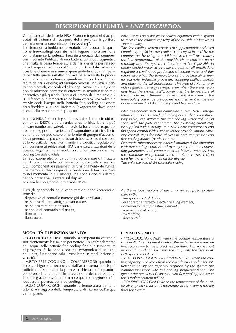
Gli apparecchi della serie NRA F sono refrigeratori d’acquadotati di sistema di recupero della potenza frigoriferadell’aria esterna denominato “free-cooling”. Il sistema di raffreddamento gratuito dell’acqua (da qui ilnome free-cooling) consiste nell’integrare fino a sostituirecompletamente la potenza frigorifera erogata dai compres-sori mediante l’utilizzo di una batteria ad acqua aggiuntivache sfrutta la bassa temperatura dell’aria esterna per raffred-dare l’acqua di ritorno dall’impianto. Con tale sistema èpossibile ottenere in maniera quasi gratuita acqua refrigera-ta per tutte quelle installazioni ove ne è richiesta la produ-zione in servizio continuo e quindi anche con basse tempe-rature dell’aria esterna; ad esempio processi industriali, cen-tri commerciali, ospedali ed altre applicazioni civili. Questotipo di soluzione permette di ottenere un sensibile risparmioenergetico : già quando l’acqua di ritorno dall’impianto è 2°C inferiore alla temperatura dell’aria esterna una valvola atre vie devia l’acqua nella batteria free-cooling per esserepreraffreddata e quindi inviata all’evaporatore dove vieneportata alla temperatura di progetto.
Le unità NRA free-cooling sono costituite da due circuiti fri-goriferi ad R407C e da un unico circuito idraulico che puòattivare tramite una valvola a tre vie la batteria ad acqua delfree-cooling posta in serie con l’evaporatore a piastre. Il cir-cuito idraulico può essere o no fornito di gruppo d'accumu-lo. La presenza di più compressori di tipo scroll ed il controllodella velocità dei ventilatori tramite il dispositivo regolatore digiri, consente ai refrigeratori NRA varie parzializzazioni dellapotenza frigorifera sia in modalità solo compressori che free-cooling (parziale o totale).La regolazione elettronica con microprocessore ottimizzataper il funzionamento con free-cooling controlla e gestiscetutti i componenti e i parametri di funzionamento dell'unità;una memoria interna registra le condizioni di funzionamen-to nel momento in cui insorga una condizione di allarme,per poi poterle visualizzare sul display.Le unità hanno grado di protezione IP 24.
Tutti gli apparecchi nelle varie versioni sono corredati diserie di:- dispositivo di controllo numero giri dei ventilatori, - resistenza elettrica antigelo evaporatore, - resistenza carter compressore, - pannello di comando a distanza, - filtro acqua, - flussostato.
MODALITÀ DI FUNZIONAMENTO:- SOLO FREE-COOLING: quando la temperatura esterna èsufficientemente bassa per permettere un raffreddamentodell’acqua nelle batterie free-cooling fino alla temperaturadi progetto. E’ la condizione più economica di utilizzodell’unità, funzionano solo i ventilatori in modulazione divelocità.- MISTO FREE-COOLING + COMPRESSORI: quando lapotenza frigorifera recuperata dall’aria esterna non è piùsufficiente a soddisfare la potenza richiesta dall’impianto icompressori funzionano in integrazione del free-cooling.Tale integrazione sarà tanto minore quanto maggiore sarà ilrecupero di potenza con free-cooling. - SOLO COMPRESSORI: quando la temperatura dell’ariaesterna è maggiore della temperatura di ritorno dell’acquadall’impianto
NRA F series units are water chillers equipped with a systemto recover the cooling capacity of the outside air known as"free-cooling". This free-cooling system consists of supplementing and evencompletely replacing the cooling capacity delivered by thecompressors by using an additional water coil that utilizesthe low temperature of the outside air to cool the waterreturning from the system. This system makes it possible toobtain cooled water at virtually no cost for all installationsrequiring a continuous production of cooled water and the-refore also when the temperature of the outside air is low;for example, industrial processes, shopping malls, hospitalsand other residential applications. This type of solution pro-vides significant energy savings: even when the water retur-ning from the system is 2°C lower than the temperature ofthe outside air, a three-way valve diverts the water in thefree-cooling coil to be pre-cooled and then sent to the eva-porator where it is taken to the project temperature.
NRA free-cooling units are composed of two R407C refrige-ration circuits and a single plumbing circuit that, via a three-way valve, can activate the free-cooling water coil set inseries with the plate evaporator. The plumbing circuit maybe supplied with a storage unit. Scroll-type compressors andfan speed control with a rev governor provide various capa-city control steps for NRA chillers in both compressor andfree-cooling modes (partial or total).Electronic microprocessor control optimized for operationwith free-cooling controls and manages all the unit's opera-ting parameters and components; an internal memory logsthe conditions of operation when an alarm is triggered, tothen be able to show them on the display.The units have an IP 24 protection rating.
All the various versions of the units are equipped as stan-dard with:- fan speed control device, - evaporator antifreeze electric heating element, - compressor casing heating element, - remote control panel, - water filter, - flow switch.
OPERATING MODE- FREE-COOLING ONLY: when the outside temperature issufficiently low to permit cooling the water in the free-coo-ling coils down to the project temperature. This is the mosteconomic condition for using the unit, only the fans workwith speed modulation- MIXED FREE-COOLING + COMPRESSORS: when the coo-ling capacity recovered from the outside air is no longer suf-ficient to satisfy the capacity required by the system thecompressors work with free-cooling supplementation. Thegreater the recovery of capacity with free-cooling, the lowerthis supplementation will be. - COMPRESSORS ONLY: when the temperature of the outsi-de air is greater than the temperature of the water returningfrom the system
DESCRIZIONE DELL’UNITÀ • UNIT DESCRIPTION
6 Aermec S.p.A.

VERSIONI:-BASE (°) rappresenta la configurazione più economica otte-nuta calibrando gli scambiatori a pacco alettato per consen-tire un corretto funzionamento del refrigeratore con tempe-rature dell'aria esterna non superiori a 41 - 42°C.-ALTA TEMPERATURA (A) consente attraverso il potenzia-mento dello scambiatore a pacco alettato, di ampliare ilimiti operativi arrivando fino ad una temperatura massimadell'aria esterna di 46°C. A parità di condizioni di funzionamento ha prestazionisuperiori alla versione base.-SILENZIATA (L) rappresenta i modelli configurati per unfunzionamento particolarmente silenzioso.
Tutte le versioni sono dotate di serie di dispositivo regolato-re velocità dei ventilatori
CAMPO D’IMPIEGOTutti i refrigeratori, nelle varie versioni, possono produrreacqua refrigerata fino a 4° C; per temperature inferiori, èprevista una versione (Y) "Bassa Temperatura acqua pro-dotta", con una apposita valvola termostatica.
REFRIGERATORI con ACCUMULOGli apparecchi con accumulo montano di serie la resistenzaelettrica antigelo.Il gruppo di pompaggio dei refrigeratori con accumulo è adalta prevalenza prevede come opzione una pompa di riser-va (opzione non disponibile per le grandezze 600, 650,700) gestita dalla scheda elettronica, che ruota periodica-mente le pompe presenti, in modo da ottimizzarne le ore difunzionamento.
INFORMAZIONI IMPORTANTIATTENZIONE ! Porre particolare attenzione alle condizionidi installazione, ubicazione, collegamenti idraulici ed elet-trici, tensione di alimentazione.ATTENZIONE !Per gli apparecchi destinati a funzionare con bassa tempera-tura dell’aria (comprese le pompe di calore), prima di ognimessa in funzione dell'unità (o al termine di ciascun perio-do di pausa prolungato) è d'estrema importanza che l'oliodel carter compressore sia stato preventivamente riscaldato,tramite alimentazione delle apposite resistenze elettriche,per un periodo di almeno 8 ore.La resistenza carter viene alimentata automaticamente allasosta dell’unità, purchè l’unità venga mantenuta sotto ten-sione.
VERSIONS:-STANDARD (°) this is the most economic configuration,which is obtained by calibrating the finned heat exchangerbanks to allow proper operation of the refrigerator at exter-nal air temperatures not exceeding 41 - 42°C.-HIGH TEMPERATURE (A) this, by increasing the power inthe finned heat exchanger bank, allows working limits to beextended up to a maximum external air temperature of46°C. -LOW NOISE (L) this indicates models configured for parti-cularly low noise operation.
All versions are equipped with fan speed adjustment device.
FIELD OF USEThe various versions of all chillers are capable of producingwater cooled to 4° C; for lower temperatures, the cold onlymodels alone include a "Low Temperature" version (Y),with a special thermostat valve.
CHILLERS with STORAGE TANKIn appliances with storage tank, the antifreeze resistor is fit-ted as a standard accessory.The pump unit in chillers with storage tank are high head,and includes the option of a reserve pump (not available forsizes 600, 650, 700), managed by the electronic card,which carried out periodic rotation of the pumps fitted, soas to optimise working hours.
IMPORTANT INFORMATIONWARNING ! Particular attention must be paid to the instal-lation conditions, location, connection to the water andpower supply, supply voltage.WARNING ! For appliances that are to be operated at low air temperatu-res (including the heat pumps), before starting up the uniteach time (or after each prolonged stoppage) it is extremelyimportant that the oil in the compressor casing be pre-hea-ted for at least 8 hours, by powering the special resistors.The casing resistor is powered automatically when the unitpauses, provided the power supply is not turned off.
NRA Fc Cod. 6871970_00 7

SCELTA DELL’UNITA’I refrigeratori della serie NRA sono disponibili in 9 grandez-ze; combinando opportunamente le numerose opzionidisponibili è possibile configurare ciascun modello dellaserie, al fine di rispondere alla più svariate esigenze impian-tistiche.
Regole di configurazione:Il paragrafo “Scelta dell’ unità” sono elencate tutte le vocinecessarie per la compilazione della sigla commerciale (nei15 campi che la compongono).NB: il simbolo (°) rappresenta le opzioni standard.Nel configurare l'unità si ricordi che non tutte le combina-zioni sono possibili. Di seguito sono riportate le principali limitazioni da tenerepresenti.
- NRA 275 • 300 • 325 • 350 sono disponibili solo in ver-sione silenziata (L) o alta temperatura (A).- NRA 500 • 550 • 600 • 650 • 700 con produzione diacqua a -10 °C: è disponibile solo la versione (YA) (altatemperatura con produzione di acqua a -10 °C); per la con-figurazione di tutte le altre versioni (Y) si raccomanda diconsultare la sede .
Esempio di configurazione:Si richiede un refrigeratore d'acqua con le seguenti caratte-ristiche:-potenza frigorifera resa (alle condizioni nominali di fun-zionamento): 130 kW.
-refrigerante: R407C (standard).-versione silenziata.-batterie con pacco alettato in alluminio.-evaporatore a norma PED.-alimentazione a 400V-3-50Hz con protezione compresso-ri costituita da magnetotermici.
-gruppo d'accumulo ad alta prevalenza.L'unità rispondente alle suddette caratteristiche tecniche èidentificata dalla seguente sigla commerciale:
NRA 650 ° ° ° L ° ° ° F3
UNIT SELECTIONNRA series chillers are available in 9 sizes; by combiningthe various options available it is possible to set up eachmodel in the series to meet the widest possible range ofsystem requirements.
Configuration rules:The paragraph "Selecting a unit" lists all the items necessaryto fill in the sale code (which is made up of 15 fields).NB: the symbol (°) represents the standard options.When configuring the unit, remember that not all combi-nations are possible. The following are the main restrictions that you must bear inmind.
- NRA 275 • 300 • 325 • 350 are available in the low noise(L) or high temperature (A) version only.- NRA 500 • 550 • 600 • 650 • 700 with water producedat - 10°C: YA version only (high temperature with waterproduced at - 10°C) is available. For all other configura-tions including Y, please contact the company.
Example of configuration:The customer requires a water chiller with the followingcharacteristics:-actual cooling capacity (at rated working conditions): 130kW.-refrigerant: R407C (standard).-low noise version.-finned aluminium bank coils.-evaporator complying with PED standards.-400V-3-50Hz power supply with thermomagnetic cutoutsprotecting the compressors.-high head storage tank group.The unit that fulfills with the above technical characteristicsis indicated with the following sales code:
NRA 650 ° ° ° L ° ° ° F3
8 Aermec S.p.A.

Campi 1, 2 e 3 NRACampi 4, 5 e 6 Grandezza:
275 • 300 • 325 • 350500 • 550 • 600 • 650 • 700
Campo 7 Campo d’impiego° standardY versione per bassa temperatura, acqua
prodotta fino a -10°C Campo 8 Modello
° Solo freddoCampo 9 Recupero di calore
° Senza recuperatoreCampo 10 Versione
° baseL SilenziataA Alta temperatura
Campo 11 Batterie° Alette batterie in alluminioR Alette batterie in RameS Alette batterie in rame Stagnato
Campo 12 Evaporatore° A norme PEDG A norme TÜV-D (Germania)P A norme UDT-PL (Polonia)
Campo 13 Alimentazione° 400V-3-50Hz; compressori protetti con
magnetotermici4 230V-3-50Hz; compressori protetti con
magnetotermici9 500V-3-50Hz; compressori protetti con
magnetotermiciCampi 14 e 15 Accumulo
F0 Senza accumuloF3 Accumulo alta prevalenza
senza pompa di riservaF4* Accumulo alta prevalenza
e pompa di riserva
Field 1, 2 and 3 NRAField 4, 5, and 6 Size:
275 • 300 • 325 • 350500 • 550 • 600 • 650 • 700
Field 7 Field of application° standard equipmentY low water temperature up to -10°C
Field 8 Model° Cooling only
Field 9 Heat recover° Without recovery
Field 10 Version° StandardL Low noiseA High temperature
Field 11 Coils° Finned aluminium coilsR Finned copper coilsS Finned tinned copper coils
Field 12 Evaporator° To PED standard G To TÜV-D standard (Germany)P To UDT-PL standard (Poland)
Field 13 Power supply° 400V-3-50Hz; compressors protected by
thermal-magnetic circuit breakers4 230V-3-50Hz; compressors protected by
thermal-magnetic circuit breakers9 500V-3-50Hz; compressors protected by
thermal-magnetic circuit breakersFields 14 and 15 Storage tank
F0 Without storage tankF3 Storage high head without reserve pump
F4* Storage high head and reserve pump
ATTENZIONE: le opzioni standard sono rappresentate dalsimbolo (°).(*) Opzione non disponibile per le grandezze 600, 650, 700
IMPORTANT: standard options are marked by the symbol (°).
(*) Option not available for sizes 600, 650, 700
CONFIGURATORE CONFIGURATION
NRA Fc Cod. 6871970_00 9

�
�
�
�
�
�
��
�
��
��
1 Scambiatore free-cooling • free-cooling heat exchanger2 Condensatore ad aria • Air condenser3 Evaporatore • Evaporator4 Filtro acqua • Water filter5 Flussostato • Flow swich6 Tastiera di comando • Control keypad
7 Quadro elettrico • Electric panel8 Struttura portante • Frame9 Gruppo ventilante • Fan assembly10 Compressore • Compressor14 Pannello comandi remoto • Remote control panel15 Valvola 3 vie • 3-way valve
COMPONENTI PRINCIPALI NRA F0 • MAIN COMPONENTS NRA F0
NRA Free-Cooling senza accumuloNRA Free-Cooling without storage tank
�����
14
10 Aermec S.p.A.

�
�
��
�
���
�
��
��
��
��
��
1 Scambiatore free-cooling • free-cooling heat exchanger2 Condensatore ad aria • Air condenser3 Evaporatore • Evaporator4 Serbatoio di accumulo • Storage tank5 Filtro acqua • Water filter6 Flussostato • Flow swich7 Pompa di circolazione • Circulation pump8 Vaso di espansione • Expansion Vessel
9 Tastiera di comando • Control keypad10 Quadro elettrico • Electric panel11 Struttura portante • Frame12 Gruppo ventilante • Fan assembly13 Compressore • Compressor14 Pannello comandi remoto • Remote control panel15 Valvola 3-vie • 3-way valve
COMPONENTI PRINCIPALI NRA F3 - F4 • MAIN COMPONENTS F3 - F4
NRA Free-Cooling con accumuloNRA Free-Cooling with storage tank
�����
14
NRA Fc Cod. 6871970_00 11

DESCRIZIONE DEI COMPONENTICOMPONENTI CIRCUITO FRIGORIFEROCOMPRESSORE Compressori ermetici di tipo scroll corredati, di serie, dellaresistenza elettrica.La resistenza viene alimentata automaticamente alla sostadell’unità, purchè l’unità venga mantenuta sotto tensione.Il vano compressori è isolato acusticamente.SCAMBIATORE REFRIGERANTE - ACQUA (EVAPORATORE)Del tipo a piastre (AISI 316), a doppio circuito frigorifero ecircuiti acqua-refrigerante alternati. E' isolato esternamentecon materiale a celle chiuse per ridurre le dispersioni termi-che. Corredato di serie della resistenza elettrica antigelo.SCAMBIATORE LATO ARIA (CONDENSATORE)È realizzato con tubi di rame ed alette in alluminio bloccatemediante espansione meccanica dei tubi. È del tipo ad altaefficienza.FILTRO DEIDRATATOREDi tipo meccanico realizzato in ceramica e materiale igro-scopico, in grado di trattenere le impurità e le eventualitracce di umidità presenti nel circuito frigorifero.RUBINETTI DEL LIQUIDO E PREMENTE Consentono di intercettare il flusso del fluido refrigerante incaso di manutenzione straordinaria.SPIA DEL LIQUIDOServe per verificare la carica di gas frigorigeno e l'eventualepresenza di umidità nel circuito frigorifero.VALVOLA SOLENOIDEInterviene allo spegnimento del compressore interrompendola migrazione di gas frigorigeno liquido verso l'evaporatore.VALVOLA TERMOSTATICALa valvola con equalizzatore esterno posto all'uscita dell'e-vaporatore, modula l'afflusso di gas all'evaporatore in fun-zione del carico termico in modo da assicurare un sufficien-te grado di surriscaldamento al gas di aspirazione.VALVOLA UNIDIREZIONALE Consente il passaggio del refrigerante in una sola direzione.
TELAIO E VENTILATORISTRUTTURA PORTANTERealizzata in lamiera di acciaio zincata a caldo, di adegua-to spessore, è verniciata con polveri poliuretaniche pergarantire la resistenza agli agenti atmosferici.GRUPPO VENTILANTEDi tipo elicoidale, bilanciato staticamente e dinamicamen-te. Gli elettroventilatori sono protetti elettricamente coninteruttori magnetotermici. E' provvisto di griglia di prote-zione secondo norme CEI EN 60335-2-40.
COMPONENTI ELETTRICIQUADRO ELETTRICOContiene la sezione di potenza e la gestione dei controlli edelle sicurezze. È conforme alle norme CEI 60204-1, e alleDirettive sulla compatibilità elettromagnetica EMC89/336/CEE e 92/31/CEE.SEZIONATORE BLOCCAPORTAPer sicurezza è possibile accedere al quadro elettrico solotogliendo tensione agendo sulla leva di apertura del quadrostesso. E’ possibile bloccare tale leva con uno o più lucchet-ti durante interventi di manutenzione per impedire unaindesiderata messa in tensione della macchina.TASTIERA DI COMANDOConsente il controllo completo dell'apparecchio. Per una piùdettagliata descrizione si faccia riferimento al manuale d'uso.PANNELLO COMANDO A DISTANZAConsente di eseguire a distanza le operazioni di comandodel refrigeratore.
DESCRIPTION OF COMPONENTSCOMPONENTS OF REFRIGERANT CIRCUITCOMPRESSORHermetic scroll type compressors, fitted with electric heateras standard accessory.The resistor is powered automatically when the unit pauses,provided the power supply is not turned off.The compressor compartment is soundproofed.EXCHANGER WATER - REFRIGERANT (EVAPORATOR)Plate type (AISI 316), with double cooling circuit and alter-nating water-refrigerant circuits. Insulated externally withclosed cell material, to reduce heat loss. Equipped with standard anti-freeze electric heater.EXCHANGER AIR SIDE (CONDENSER)Features copper tube bundle with aluminium fins, fixed bymechanical expansion of tubes. High-efficiency type.DRIER FILTERMechanical filter made from ceramic and hygroscopic mate-rial, designed to capture impurities and all residual moisturein the cooling circuit.SUCTION SIDE LIQUID AND DISCHARGE GAS SHUT-OFF VALVES These valves provide the facility to intercept the flow ofrefrigerant to allow supplementary maintenance work to becarried out.LIQUID INDICATORIndicates the level of the refrigerant gas charge and the pre-sence of moisture in the cooling circuit.SOLENOID VALVECuts in when the compressor shuts down to stop flow ofrefrigerant gas to the evaporator.THERMOSTATIC VALVEThe valve, with equaliser at the evaporator outlet, regulatesgas flow to the evaporator according to the thermal load,ensuring a sufficient degree of superheating of intake gas.NON RETURN VALVEAllows refrigerant to flow in only one direction.
FRAME AND FANSFRAMEMade from hot-galvanised thick sheet metal, painted withstoved polyurethane powder for resistance to atmosphericagents.FAN ASSEMBLYStatically and dynamically balanced axial flow type. The fanunits are electrically protected with thermal-magnetic circuitbreakers and mechanically protected with metal anti-intru-sion grilles following CEI EN 60335-2-40 standards.
ELECTRICAL COMPONENTSELECTRIC PANELFeatures power section, regulation of controls and safetydevices. Compliant with CEI 60204-1 standards andDirectives EMC 89/336/CEE and 92/31/CEE governing elec-tromagnetic compatibility.DOOR LOCK DISCONNECTORFor safety's sake it is only possible to access the electricpanel after cutting off the power supply using the lever thatopens the panel itself. This lever can be fastened with oneor more locks during maintenance operations, to preventpower from being restored to the machine accidentally.CONTROL KEYPADGives complete control over unit functions. For more informa-tion, refer to the user manual..REMOTE CONTROL PANELFor remote control of chiller operation.
12 Aermec S.p.A.

COMPONENTI IDRAULICISCAMBIATORE ARIA - ACQUA (FREE-COOLING)Attraversata da acqua per il funzionamento in free-cooling.È realizzata con tubi di rame ed alette in alluminio bloccatemediante espansione meccanica dei tubi. È del tipo ad altaefficienza.FILTRO ACQUA (Installato di serie)Consente di bloccare ed eliminare eventuali impurità pre-senti nei circuiti idraulici. Presenta al suo interno una magliafiltrante con fori non superiori ad un millimetro. E' indispen-sabile per evitare gravi danni allo scambiatore a piastre.VALVOLA 3 VIEPresente sul lato acqua del circuito free-cooling, è una val-vola deviatrice ON-OFF comandata tramite servocomandoelettrico.GRUPPO DI RIEMPIMENTO (*)È fornito di manometro per la visualizzazione della pressio-ne dell’impianto.POMPA DI CIRCOLAZIONE (*)Abbinata esclusivamente al serbatoio offre, in funzionedelle caratteristiche della pompa scelta una prevalenza utileper vincere le perdite di carico dell'impianto.Qualora sia prevista la possibilità della pompa di riserva ilsoftware residente nella scheda di regolazione provvedealla rotazione delle pompe per equilibrare il numero di oredi funzionamento.SERBATOIO DI ACCUMULO (*)E' in acciaio e la capienza è di 300 litri. Al fine di ridurre ledispersioni termiche ed eliminare il fenomeno della forma-zione di condensa, viene coibentato mediante materialepoliuretanico di adeguato spessore. Monta di serie una resistenza elettrica antigelo comandatadalla sonda antigelo inserita nel serbatoio.VALVOLA DI SFIATO (*)Di tipo automatico montata sulla parte superiore del serba-toio; provvede a scaricare eventuali sacche d’aria presentinel medesimo. È intercettata da un rubinetto per facilitarnel’eventuale sostituzione.VASO DI ESPANSIONE (*)E' del tipo a membrana con precarica di azoto.
(*) Componente del circuito idraulico presente solo nelleunità con accumulo
COMPONENTI DI SICUREZZA E CONTROLLOFLUSSOSTATO (Installato di serie)Ha il compito di controllare che ci sia circolazione d'acqua.In caso contrario blocca l’unità. Il flussostato è tarato in fab-brica per una portata corrispondente al 75% della portatanominale (∆t = 5°C)RESISTENZA ELETTRICA ANTIGELO EVAPORATORE(Installata di serie)Il suo funzionamento viene comandato dalla sonda antigeloposizionata nell'evaporatore a piastre. L'attivazione avvienequando la temperatura dell'acqua è +3°C mentre il suodisinserimento avviene con temperatura dell'acqua di +5°C.Il software dedicato, residente nella scheda di regolazione,gestisce la resistenza elettrica.TRASDUTTORE DI ALTA PRESSIONEPermette di visualizzare sul display della scheda a micro-processore il valore della pressione di mandata del com-pressore (uno per circuito). Posto sul lato ad alta pressionedel circuito frigorifero, arresta il funzionamento del com-pressore in caso di pressioni anomale di lavoro.TRASDUTTORE DI BASSA PRESSIONEPermette di visualizzare sul display della scheda a micro-processore il valore della pressione di aspirazione del com-pressore (uno per circuito). Posto sul lato a bassa pressionedel circuito frigorifero, arresta il funzionamento del com-pressore in caso di pressioni anomale di lavoro.
HYDRAULIC COMPONENTSAIR - WATER HEAT EXCHANGER (FREE-COOLING)Crossed by water for free-cooling operation. It is made withcopper tubes and aluminium fins locked by the mechanicalexpansion of the tubes. High efficiency type.WATER FILTER (Supplied as a standard accessory)Allows any impurities in the hydraulic circuits to be collec-ted and eliminated. Interior houses a filter mesh with holesnot exceeding one millimetre. It is essential to preventserious damage to the plate heat exchanger. 3 - WAY VALVEOn the water side of the free-cooling circuit there is an ON-OFF diverter valve controlled by an electric servo control.FILLING ASSEMBLY (*)Features pressure gauge for measuring system pressurevalues.CIRCULATION PUMP (*)Fitted to the tank, provides the head required to compensa-te for pressure drops in the system.If the option of a reserve pump is foreseen, in this case thesoftware resident in the regulation card will provide for alter-nation of the pump to keep the number of working hourseven.
STORAGE TANK (*)Steel tank with 300-litre capacity. To reduce heat loss andeliminate the formation of condensation, it is insulated withlayer of polyurethane material of adequate thickness. Equipped as standard with an electric antifreeze heatercontrolled by the antifreeze sensor located in the tank.BLEED VALVE (*)Automatic valve fitted in upper section of tank. Dischargesresidual air present in tank. It is intercepted by a tap to facili-tate replacement when necessary.
EXPANSION VESSEL (*)Diaphragm type pre-charged with nitrogen.
(*) = Hydraulic circuit component only present in unitswith storage tank.
SAFETY AND CONTROL DEVICESFLOW SWITCH (Supplied as a standard accessory)Has the job of checking the circulation of water. If there isno circulation, it blocks the unit. The flow switch is factoryset for a flow rate corresponding to 75% of the nominalflow rate (∆t = 5°C)EVAPORATOR ANTI-FREEZE ELECTRIC HEATER (Suppliedas a standard accessory)This is turned on by the antifreeze probe, located in theplate evaporator. It turns on when the water temperaturedrops to +3°C and turns off again when the temperaturereaches +5°C. The resistor is managed by a dedicatedsoftware, resident in the regulation card.HIGH PRESSURE SENSORDisplays on the microprocessor the delivery pressure value ofcompressors (one for each circuit); standard equipment onheat pump and silent versions. Positioned on the high pressu-re side of refrigerant circuit. It cuts out compressor operation inthe event of abnormal operating pressure.LOW PRESSURE SENSORDisplays on the microprocessor the delivery pressure value ofcompressors (one for each circuit); standard equipment onheat pump and silent versions. Positioned on the low pressureside of refrigerant circuit. It cuts out compressor operation inthe event of abnormal operating pressure.
NRA Fc Cod. 6871970_00 13

PRESSOSTATO DI ALTA A taratura variabile, posto sul lato ad alta pressione del cir-cuito frigorifero, arresta il funzionamento del compressorein caso di pressioni anomale di lavoro.VALVOLA DI SICUREZZA CIRCUITO FRIGORIFEROTarata a 30 bar (22 bar nelle versioni a pompa di calore),interviene scaricando la sovrapressione in caso di pressionianomale.DISPOSITIVO DI REGOLAZIONE DEI VENTILATORI Tale dispositivo è costituito da una scheda elettronica diregolazione che varia il numero di giri dei ventilatori inbase alla pressione di condensazione, letta dal trasduttoredi alta pressione, al fine di mantenerla a valori adeguati.Tale logica consente un corretto funzionamento in raffred-damento con temperature esterne inferiori a 20°C; in casodi funzionamento in modalità free-cooling tale dispositivoregola la velocità dei ventilatori in funzione del caricorichiesto.
VALVOLA DI SICUREZZA CIRCUITO IDRAULICO (*)Tarata a 6 Bar, e con lo scarico convogliabile intervienescaricando la sovrapressione in caso di pressioni anomale.(*) Componente del circuito idraulico presente solo nelleunità con accumulo.
- sistema di interblocco porta;- magnetotermico protezione compressori;- magnetotermico protezione ventilatori;- magnetotermico protezione ausiliario;- pannello comandi remoto semplificato composto da:
commutatore ON/OFF/Reset;commutatore Estate/Inverno;
segnalazione riassunto allarmi.
SCHEDA A MICROPROCESSOREComposta da scheda di gestione e controllo e da scheda divisualizzazione. Funzioni svolte:
• regolazione temperatura acqua ingresso evaporatorecon termostatazione fino a 4 gradini e controllo propor-zionale - integrale sulla velocità dei ventilatori.
• ritardo avviamento compressori.• funzionamento come refrigeratore con possibilità di inte-
grazione capacità frigorifera tramite “free-cooling” .• rotazione sequenza compressori.• gestione dispositivo bassa temperatura (accessorio).• conteggio ore funzionamento compressori.• start/stop.• reset.• memoria permanente degli allarmi.• autostart dopo caduta di tensione.• messaggistica multilingue.• funzionamento con controllo locale o remoto.• visualizzazione stato macchina:
ON/OFF compressori;riassunto allarmi.
• gestione allarmi:alta pressione;flussostato;bassa pressione;antigelo;sovraccarico compressori;sovraccarico ventilatori;sovraccarico pompe.
• visualizzazione dei seguenti parametri:temperatura ingresso acqua;temperatura ingresso acqua evaporatore;temperatura uscita acqua;delta T;alta pressione;bassa pressione;tempo attesa di riavvio.
• visualizzazione allarmi.
HIGH PRESSURE SWITCH Variable setting, located on the high pressure side of thecooling circuit, the switch shuts compressor operation in theevent of abnormal operating pressure levels.COOLING CIRCUIT SAFETY VALVESet to 30 bar (22 bar in heat pump versions), it intervenes todischarge excess pressure if the pressure level rises abovenormal.FAN CONTROL DEVICE This device is composed of an electronic control card thatvaries the speed at which the fans turn according to thecondensation pressure, measured by the high-pressure tran-sducer, in order to keep it at suitable levels. This logic per-mits correct operation when cooling with outside tempera-tures under 20°C; when working in free-cooling mode thisdevice regulates the fans on top speed.
HYDRAULIC CIRCUIT SAFETY VALVE (*)Set to 6 Bar with ductable discharge, it intervenes todischarge excess pressure if the pressure level rises abovenormal.(*) = Hydraulic circuit component only present in unitswith storage tank.
- door interlocking system.- compressor thermal-magnetic circuit breaker;- fan thermal-magnetic circuit breaker;- auxiliary thermal-magnetic circuit breaker;- simplified remote control panel featuring:
ON/OFF/Reset switch;Summer/Winter mode switch;
alarms summary display.
MICROPROCESSORComprises control board and display panel. Functions include:
• evaporator inlet water temperature control with thermo-statting up to 4 steps and proportional - integral controlon the fan speed.
• compressor start-up delay;• chiller operating mode with possibility of additional
cooling capacity using “free-cooling”;• compressor sequence rotation;• low temperature control device (accessory);• compressor operation timer;• start/stop control;• reset;• permanent alarm memory;• automatic restart after power failure;• multi-language messages;• local or remote-control operation;• machine status display:
compressors ON/OFF;alarms summary;
• alarm control:high pressure;flow switch;low pressure;anti-freeze;compressor overload;fan overload;pumps overload;
• display of the following parameters:water inlet temperature;evaporator water inlet temperature;water outlet temperature;delta T;high pressure;low pressure;restart delay time.
• alarm display.• settings:
14 Aermec S.p.A.

• impostazioni set:a) senza parola d'ordine:
set freddo;differenziale totale;
b) con parola d'ordine:set antigelo;tempo esclusione bassa pressione;linguaggio display;codice di accesso.
Di seguito sono descritte in dettaglio le principali funzionigestite dalla scheda a microprocessore. Per ulteriori infor-mazioni , si veda il manuale utente.
– ACCENSIONE-SPEGNIMENTO COMPRESSORILa scheda gestisce l'accensione e lo spegnimento dei com-pressori in funzione della temperatura dell'acqua di ritornodall'impianto e della potenza frigorifera erogata dalle batte-rie ad acqua. La lettura delle temperature viene effettuata tra-mite sonda posta in ingresso all’evaporatore-uscita free-coo-ling.
– TEMPORIZZAZIONE DEI COMPRESSORI E DEI VENTILATORIDi seguito sono elencati tutti i tempi di attesa tra un avvia-mento e l'altro dei carichi interni. Si vuole comunque evi-denziare che il singolo compressore rimane sempre fermoper almeno un minuto dopo lo spegnimento e devono inol-tre essere trascorsi almeno 5 minuti dall’ultimo avviamento.– tempo minimo per il riavvio compressore: 60 sec.– attesa aggiuntiva riavvio compressore se il tempo di fun-
zionamento > 240 sec.: 0 sec.– attesa aggiuntiva riavvio compressore se il tempo di fun-
zionam. < 240 sec.: 240sec. - tempo di funzion.– ritardo tra compressori: 30 secondi.– tempo minimo di funzionamento per circuito frigorifero :
2 minuti.
– AUTOSTARTRiavvia l’unità dopo mancanza di tensione. La scheda amicroprocessore è dotata di particolari memorie che per-mettono di memorizzare, permanentemente, le impostazio-ni di funzionamento dell’unità prima dell’interruzione ditensione.Al ritorno di tensione, se il parametro AUTOSTART è:
– 0 (Off): la macchina non riparte;– 1 (On): la macchina riparte anche se era in Stand-By;– 2 (Auto): la macchina si riconfigura come al momento
della mancanza di tensione.
– ROTAZIONE DEL FUNZIONAMENTO DEI COMPRESSORIIl microprocessore conteggia le ore di funzionamento deicompressori e con queste gestisce la rotazione dei compres-sori. È possibile azzerare questi parametri dal pannello abordo macchina (solo con il codice di accesso).
– GESTIONE DEGLI ALLARMILa scheda elettronica gestisce le anomalie di funzionamentoin pre-allarmi ed allarmi.I preallarmi sono intesi come segnalazioni di temporaneeanomalie di funzionamento provocate da elementi esterni;esse comportano il passaggio della macchina dallo stato difunzionamento allo stato di stand-by e vengono segnalatesul display pannello comandi. Quando la scheda rileva chetali anomalie sono state eliminate la macchina riparte auto-maticamente senza necessità di essere resettata.La scheda elettronica gestisce il passaggio in allarme da pre-allarme quando questo continua a persistere, bloccando ilfunzionamento del circuito interessato.La scheda a microprocessore segnala l’intervento di unallarme mediante l’accensione di un led rosso sia sul pan-nello a bordo macchina sia sul pannello comandi remoto.È inoltre a disposizione sulla scheda un contatto pulito indeviazione che viene attivato in caso d’allarme (morsettieraM1: V = 250V, Imax = 1 A).Il microprocessore memorizza in modo permanente gli allar-
a) without password:set cooling;total differential;
b) with password:set anti-freeze;low pressure off time;display language;access code.
The main functions controlled by the microprocessor aredescribed below (for more information, refer to the usermanual).
– COMPRESSOR ON-OFF CONTROLThe card controls switching the compressors on and offaccording to the temperature of the water returning from thesystem and the cooling capacity delivered by the water coils.Water temperature is measured by a probe at the evaporatorinlet-free-cooling outlet.
– COMPRESSOR AND FAN TIME CONTROLThe delay times between start-ups are given below. Notethat single compressor shut down for at least one minuteafter deactivation; at least 5 minutes must elapse since thelatest start-up.- minimum delay for compressor start-up: 60 sec.- additional delay for compressor start-up when operatingtime is > 240 sec.: 0 sec.- additional delay for compressor start-up when operatingtime is < 240 sec.: 240sec. - operating time.- delay between compressors: 30 seconds.– minimum operating time for refrigerant circuit : 2 minutes
– AUTOMATIC RESTARTThe unit is automatically restarted after a power failure. Themicroprocessor permanently stores the unit operating set-tings.When the power supply is restored, the AUTOSTART para-meter is:
– 0 (Off): the unit does not restart;– 1 (On): the unit restarts (even if previously set to stand-by mode);– 2 (Auto): the unit resets to the configuration prior to thepower failure.
– COMPRESSOR OPERATION ROTATIONIl microprocessore conteggia le ore di funzionamento deicompressori e con queste gestisce la rotazione dei compres-sori. È possibile azzerare questi parametri dal pannello abordo macchina (solo con il codice di accesso).
– ALARM CONTROLThe microprocessor also manages operating anomaliesthrough pre-alarm and alarms.Pre-alarms refer to temporary operating faults caused byexternal factors; these set the unit from operating mode tostand-by, and are indicated on the control panel display.When the board detects that the faults have been elimina-ted, the unit automatically restarts without any resetting ofoperating parameters.In the event that the pre-alarm persists, the board sets themachine to alarm status and shuts down operation of thecircuit concerned.The microprocessor board indicates that an alarm has beentriggered by means of a red LED lamp on the machine andon the remote control panel.The board also features a voltage-free changeover contactthat is energised in the event of alarm (terminal board M1: V= 250V, Imax = 1 A).The microprocessor permanently stores all triggered alarms(a power failure immediately following an alarm will not
NRA Fc Cod. 6871970_00 15
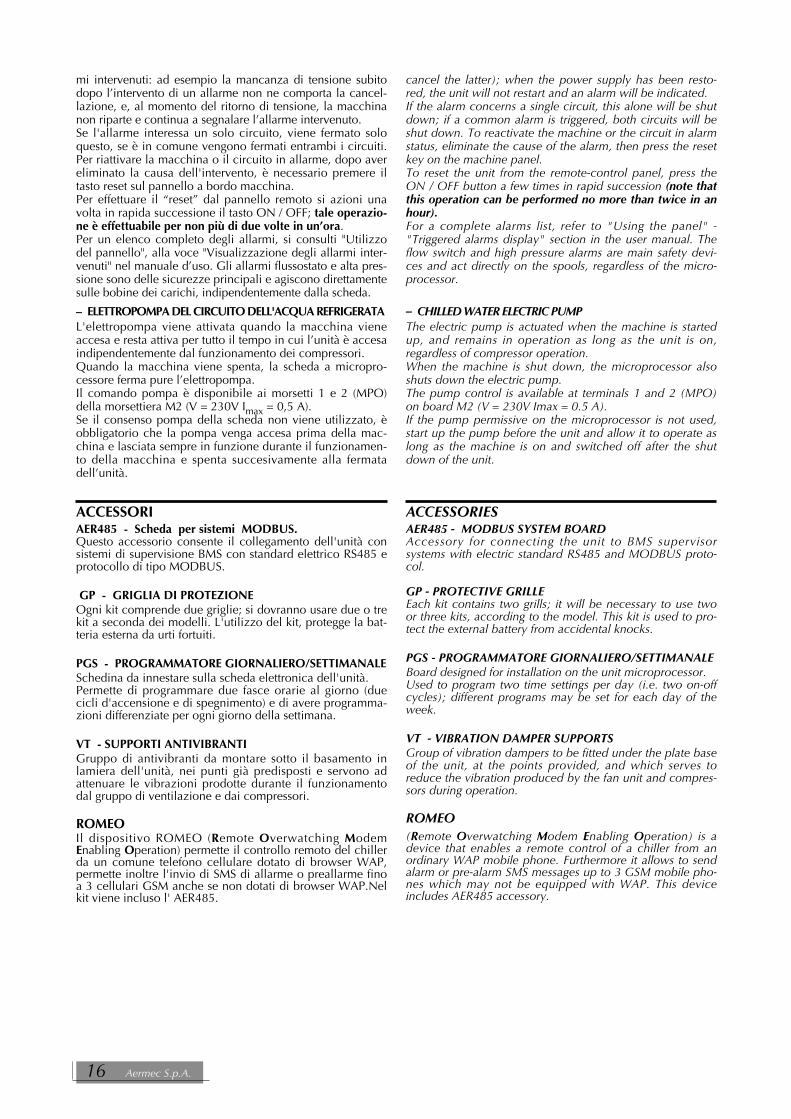
mi intervenuti: ad esempio la mancanza di tensione subitodopo l’intervento di un allarme non ne comporta la cancel-lazione, e, al momento del ritorno di tensione, la macchinanon riparte e continua a segnalare l’allarme intervenuto.Se l'allarme interessa un solo circuito, viene fermato soloquesto, se è in comune vengono fermati entrambi i circuiti.Per riattivare la macchina o il circuito in allarme, dopo avereliminato la causa dell'intervento, è necessario premere iltasto reset sul pannello a bordo macchina.Per effettuare il “reset” dal pannello remoto si azioni unavolta in rapida successione il tasto ON / OFF; tale operazio-ne è effettuabile per non più di due volte in un’ora.Per un elenco completo degli allarmi, si consulti "Utilizzodel pannello", alla voce "Visualizzazione degli allarmi inter-venuti" nel manuale d’uso. Gli allarmi flussostato e alta pres-sione sono delle sicurezze principali e agiscono direttamentesulle bobine dei carichi, indipendentemente dalla scheda.
– ELETTROPOMPA DEL CIRCUITO DELL'ACQUA REFRIGERATAL'elettropompa viene attivata quando la macchina vieneaccesa e resta attiva per tutto il tempo in cui l’unità è accesaindipendentemente dal funzionamento dei compressori.Quando la macchina viene spenta, la scheda a micropro-cessore ferma pure l’elettropompa.Il comando pompa è disponibile ai morsetti 1 e 2 (MPO)della morsettiera M2 (V = 230V Imax = 0,5 A).Se il consenso pompa della scheda non viene utilizzato, èobbligatorio che la pompa venga accesa prima della mac-china e lasciata sempre in funzione durante il funzionamen-to della macchina e spenta succesivamente alla fermatadell’unità.
ACCESSORIAER485 - Scheda per sistemi MODBUS.Questo accessorio consente il collegamento dell'unità consistemi di supervisione BMS con standard elettrico RS485 eprotocollo di tipo MODBUS.
GP - GRIGLIA DI PROTEZIONEOgni kit comprende due griglie; si dovranno usare due o trekit a seconda dei modelli. L'utilizzo del kit, protegge la bat-teria esterna da urti fortuiti.
PGS - PROGRAMMATORE GIORNALIERO/SETTIMANALESchedina da innestare sulla scheda elettronica dell'unità.Permette di programmare due fasce orarie al giorno (duecicli d'accensione e di spegnimento) e di avere programma-zioni differenziate per ogni giorno della settimana.
VT - SUPPORTI ANTIVIBRANTIGruppo di antivibranti da montare sotto il basamento inlamiera dell'unità, nei punti già predisposti e servono adattenuare le vibrazioni prodotte durante il funzionamentodal gruppo di ventilazione e dai compressori.
ROMEOIl dispositivo ROMEO (Remote Overwatching ModemEnabling Operation) permette il controllo remoto del chillerda un comune telefono cellulare dotato di browser WAP,permette inoltre l'invio di SMS di allarme o preallarme finoa 3 cellulari GSM anche se non dotati di browser WAP.Nelkit viene incluso l' AER485.
cancel the latter); when the power supply has been resto-red, the unit will not restart and an alarm will be indicated.If the alarm concerns a single circuit, this alone will be shutdown; if a common alarm is triggered, both circuits will beshut down. To reactivate the machine or the circuit in alarmstatus, eliminate the cause of the alarm, then press the resetkey on the machine panel.To reset the unit from the remote-control panel, press theON / OFF button a few times in rapid succession (note thatthis operation can be performed no more than twice in anhour).For a complete alarms list, refer to "Using the panel" -"Triggered alarms display" section in the user manual. Theflow switch and high pressure alarms are main safety devi-ces and act directly on the spools, regardless of the micro-processor.
– CHILLED WATER ELECTRIC PUMPThe electric pump is actuated when the machine is startedup, and remains in operation as long as the unit is on,regardless of compressor operation.When the machine is shut down, the microprocessor alsoshuts down the electric pump.The pump control is available at terminals 1 and 2 (MPO)on board M2 (V = 230V Imax = 0.5 A).If the pump permissive on the microprocessor is not used,start up the pump before the unit and allow it to operate aslong as the machine is on and switched off after the shutdown of the unit.
ACCESSORIESAER485 - MODBUS SYSTEM BOARDAccessory for connecting the unit to BMS supervisorsystems with electric standard RS485 and MODBUS proto-col.
GP - PROTECTIVE GRILLEEach kit contains two grills; it will be necessary to use twoor three kits, according to the model. This kit is used to pro-tect the external battery from accidental knocks.
PGS - PROGRAMMATORE GIORNALIERO/SETTIMANALEBoard designed for installation on the unit microprocessor.Used to program two time settings per day (i.e. two on-offcycles); different programs may be set for each day of theweek.
VT - VIBRATION DAMPER SUPPORTSGroup of vibration dampers to be fitted under the plate baseof the unit, at the points provided, and which serves toreduce the vibration produced by the fan unit and compres-sors during operation.
ROMEO(Remote Overwatching Modem Enabling Operation) is adevice that enables a remote control of a chiller from anordinary WAP mobile phone. Furthermore it allows to sendalarm or pre-alarm SMS messages up to 3 GSM mobile pho-nes which may not be equipped with WAP. This deviceincludes AER485 accessory.
16 Aermec S.p.A.

** = Nei modelli con accumulo •In models with storage tank.
NB = In presenza di parentesi, il numero indica la quantità necessaria.The braces indicate that installation of the combination of accessories shown is required.
TABELLA DI COMPATIBILITÀ DEGLI ACCESSORI • ACCESSORIES COMPATIBILITY TABLE
NRA F : Accessori disponibili • Available accessoriesMod. NRA 500 550 600 650 700AER 485 ✔ ✔ ✔ ✔ ✔ROMEO ✔ ✔ ✔ ✔ ✔GP 2 ✔(x 2) ✔(x 2) ✔(x 3) ✔(x 3) ✔(x 3)PGS ✔ ✔ ✔ ✔ ✔VT 10 ✔** ✔** ✔VT 11 ✔** ✔** ✔**VT 13 ✔ ✔ ✔VT 14 ✔
NRA F - L : Accessori disponibili • Available accessoriesMod. NRA-L 275L 300L 325L 350L 500L 550L 600L 650L 700LAER 485 ✔ ✔ ✔ ✔ ✔ ✔ ✔ ✔ ✔ROMEO ✔ ✔ ✔ ✔ ✔ ✔ ✔ ✔ ✔GP 2 ✔(x 2) ✔(x 2) ✔(x 3) ✔(x 3) ✔(x 3)GP 4 ✔ ✔ ✔ ✔PGS ✔ ✔ ✔ ✔ ✔ ✔ ✔ ✔ ✔VT 10 ✔** ✔** ✔** ✔** ✔** ✔** ✔ ✔VT 11 ✔** ✔** ✔**VT 13 ✔ ✔ ✔ ✔ ✔ ✔VT 14 ✔
NRA F - A: Accessori disponibili • Available accessoriesMod. NRA 275A 300A 325A 350A 500A 550A 600A 650A 700AAER 485 ✔ ✔ ✔ ✔ ✔ ✔ ✔ ✔ ✔ROMEO ✔ ✔ ✔ ✔ ✔ ✔ ✔ ✔ ✔GP 2 ✔(x 2) ✔(x 2) ✔(x 3) ✔(x 3) ✔(x 3)GP 4 ✔ ✔ ✔ ✔PGS ✔ ✔ ✔ ✔ ✔ ✔ ✔ ✔ ✔VT 10 ✔** ✔** ✔** ✔** ✔** ✔** ✔ ✔VT 11 ✔** ✔** ✔**VT 13 ✔ ✔ ✔ ✔ ✔ ✔VT 14 ✔
NRA Fc Cod. 6871970_00 17

REFRIGERATORI • CHILLERS : DATI TECNICI • TECHNICAL DATA R407CR407CRAFFREDDAMENTO • COOLING 275 F0 300 F0 325 F0 350 F0 500 F0 550 F0 600 F0 650 F0 700 F0
(°) - - - - 87 95 116 132 148❆ Potenzialità frigorifera • Cooling capacity [kW] A 54 62 71 82 91 99 120 136 160
L 50 58 66 74 82 90 112 128 144(°) - - - - 37,5 41 51 57 64
❆ Potenza assorbita totale • Total input power [kW] A 18,0 21,0 24,5 27,5 35,5 39,5 48 54 60,5L 20,5 24,0 27,5 31,0 39,5 42,5 52,5 58,5 68
(°) - - - - 2,32 2,32 2,27 2,32 2,31❆ E.E.R. [W/W] A 3,00 2,95 2,90 2,98 2,56 2,51 2,50 2,52 2,64
L 2,44 2,42 2,40 2,39 2,08 2,12 2,13 2,19 2,12(°) - - - - 14.960 16.340 19.950 22.700 25.460
❆ Portata acqua • Water flow rate [l/h] A 9.290 10.660 12.210 14.100 15.650 17.030 20.640 23.390 27.520L 8.600 9.976 11.350 12.730 14.100 15.480 19.260 22.020 24.770
❆ Perdite di carico refrigeratore senza free-cooling(°) - - - - 49 49 73 87 105
❆ Chiller pressure drops without free-cooling[kPa] A 52 46 52 70 53 53 79 92 122
L 43 39 44 57 43 43 67 82 101
FREE-COOLING • FREE-COOLING 275 F 300 F 325 F 350 F 500 F 550 F 600 F 650 F 700 F
(°) - - - - 95 98 125 150 157Potenzialità frigorifera • Cooling capacity [kW] A 53 65 69 85 96 99 127 152 161
L 51 63 67 82 93 96 123 149 156(°) - - - - 2,83 2,83 4,20 4,20 4,20
Potenza assorbita totale • Total input power [kW] A 39 46 53 60 71 2,93 4,33 4,33 4,33L 39 46 53 60 71 2,93 4,33 4,33 4,33
(°) - - - - 33,6 34,6 29,8 35,7 37,4E.E.R. [W/W] A 49,5 60,7 64,5 61,6 32,8 33,8 29,3 35,1 37,2
L 47,7 58,9 62,6 59,4 31,7 32,8 28,4 34,4 36,0(°) - - - - 14.960 16.340 19.950 22.700 25.460
Portata acqua • Water flow rate [l/h] A 9.290 10.660 12.210 14.100 15.650 17.030 20.640 23.390 27.520L 8.600 9.976 11.350 12.730 14.100 15.480 19.260 22.020 24.770
Perdite di carico totali con free-cooling (°) - - - - 62 64 93 110 134
Total pressure drops with free-cooling [kPa] A 74 67 78 104 67 69 101 116 155L 61 57 67 85 54 57 86 104 129
Tensione di alimentazione • Power supply= 400 V - 3+N - 50 Hz (±10%).
(°) = base • Standard A = Alta temperatura • High temperature L = Silenziata • Low noise
Le prestazioni sono riferite alle seguenti condizioni (NRA configurato (00) senza accumulo) :� -Pressione sonora misurata a 10 m di distanza, in campo libero con fattore di direzionalità Q = 2;❄ Funzionamento chiller (glicole 30%):
-temperatura acqua prodotta = 7 °C; ∆ t = 5 °C - temperatura aria esterna = 35 °C.Funzionamento free-cooling (glicole 30%):-temperatura ingresso acqua = 15 °C; - temperatura aria esterna = 2 °C.
Performances refer to following conditions (NRA configured (00) without storage tank) :� -Sound pressure measured at 10 mt.s in free field conditions Q = 2 .❄ Chiller mode (glycole 30%)
- temperature of processed water = 7 °C; ∆ t = 5 °C - ambient air temperature = 35 °C.free-cooling mode (glycole 30%)- temperature of inlet water = 15 °C; - ambient air temperature = 2 °C.
18A
ermec S.p.A
.

Le prestazioni sono riferite alle seguenti condizioni:NRA configurato (00) senza accumulo.
❄ - temperatura acqua prodotta = 7 °C; ∆ t = 5 °C- temperatura aria esterna = 35 °C.� - Pressione sonora misurata a 10 m di distanza, in campo libero con fattore di direzionalità Q = 2;- temperatura ingresso acqua = 15 °C; -temperatura aria esterna = 2 °C.
Performances refer to following conditions:NRA configured (00) without storage tank.
❄ - temperature of processed water = 7 °C; ∆ t = 5 °C- ambient air temperature = 35 °C.� - Sound pressure measured at 10 mt.s in free field conditions Q = 2 .
-ttemperature of inlet water = 15 °C; - ambient air temperature = 2 °C.
DATI TECNICI GENERALI • MAIN TECHNICAL DATA 275 F0 300 F0 325 F0 350 F0 500 F0 550 F0 600 F0 650 F0 700 F0Contenuto acqua evaporatore • Evaporator water content [l] 4,56 4,56 5,52 5,52 7,44 9,4 9,4 10,8 12,2Contenuto acqua totale refrigeratore
[l] 56 67 68 68 95 97 97 108 109Chiller total water contents(°) - - - - 36.000 36.000 55.000 55.000 55.000
❆ Portata aria • Total air flow [l/h] A 18.500 17.500 17.500 24.500 34.000 34.000 52.000 52.000 52.000L 19.000 18.000 18.000 25.400 17.500 20.000 44.000 44.000 44.000
Potenza assorbita dei motori ventilatori(°) - - - - 2.700 2.700 4.050 4.050 4.050
Fan motor power[W] A 940 940 940 1.250 2.800 2.800 4.200 4.200 4.200
L 940 940 940 1.250 1.400 1.400 2.100 2.400 2.400
Numero dei ventilatori(°) - - - - 2 2 3 3 3
Number of fansn° A 6 6 8 8 2 2 3 3 3
L 6 6 8 8 2 2 3 3 3(°) - - - - 870 870 870 870 870
Velocità motori ventilatori • Fan motor speed g/m•rpm A 870 870 870 870 870 870 870 870 870L 870 870 870 870 460 520 690 690 690
Compressori • Compressors n° scroll scroll scroll scroll scroll scroll scroll scroll scrollNumero compressori / circuiti
n° 2 / 2 2 / 2 2 / 2 2 / 2 3 / 2 3 / 2 4 / 2 4 / 2 4 / 2Number of compressors / circuitResistenza carter compressori
n° x [W] 2 x 75 2 x 75 2 x 75 2 x 75 3 x 75 3 x 75 4 x 75 4 x 75 4 x 75Crankcase heater power
� Pressione sonora (°) - - - - 54,5 54,5 55,0 56 56❆ Sound pressure A 48 48 49 49 54,5 54,5 55 56 56
L 48 48 49 49 46 46,5 49 49 49� Pressione sonora • Sound pressure (°) 46 46 47 47 50 50 52 52 52
DATI ELETTRICI • ELECTRICAL DATA 275 F0 300 F0 325 F0 350 F0 500 F0 550 F0 600 F0 650 F0 700 F0(°) - - - - 66,0 72,8 90,2 98,2 110
❆ Corrente assorbita* • Current absorption* [A] A 37,0 42,0 46,0 55,0 63,5 69,8 88,7 99,6 106,8L 40,0 46,0 50,0 57,5 68,8 75,4 93,8 104,0 121,5
(°) - - - - 6,7 6,7 9,0 9,0 9,0Corrente assorbita* • Current absorption* [A] A 5,5 6,0 6,0 7,6 7,2 7,2 10,2 10,2 10,2
L 5,5 6,0 6,0 7,6 7,2 7,2 10,2 10,2 10,2Corrente max. • Max.current [A] 65 68 71 77 98 104 133 142 145Corrente di spunto* • Peak current* [A] 155 161 166 209 215 222 239 250 257
Corrente assorbita motori ventilatori(°) - - - - 5,5 5,5 8,25 8,25 8,25
Fan motor power[A] A 4,8 4,8 4,8 6,4 6,0 6,0 9,0 9,0 9,0
L 4,8 4,8 4,8 6,4 2,8 2,9 4,2 4,4 4,4
*Tensione di alimentazione • Power supply= 400 V - 3+N - 50 Hz (±10%).
(°) = base • Standard A = Alta temperatura • High temperature L = Silenziata • Low noise
REFRIGERATORI • CHILLERS : DATI TECNICI • TECHNICAL DATA R407CR407C
NR
A Fc
Cod. 6871970_00 19

Per permettere una scelta agevole dell’unità vengono diseguito messe a disposizione una serie di curve, grafici,tabelle che descriviamo brevemente: Le TAV. 1, 2, 3 riportano i coefficienti correttivi (validi pertutti i modelli), da utilizzare per ricavare i valori dellapotenza frigorifera e di quella assorbita in condizioni diver-se da quelle nominali per il funzionamento con solo com-pressori e con free-cooling. Le TAV. 4, 5 riportano rispettivamente le curve delle perditedi carico acqua nel funzionamento solo refrigeratore e nelfunzionamento solo free-cooling o misto free-cooling-refri-geratore.Le TAV. 6, 7 e 8, 9 sono tabelle di correzione da impiegarequando le condizioni di utilizzo del refrigeratore rientrano in unodi questi casi: presenza di acqua glicolata, ∆t diversi dal nomina-le, presenza di sporco, temperatura media dell'acqua diversa da10°C. La TAV. 10 riporta il contenuto massimo acqua dell' impianto.Le TAV. 11 e 12 riportano le curve di prevalenza utile deimodelli NRA con gruppo di pompaggio ad alta prevalenzarispettivamente in funzionamento con o senza free-cooling.L TAV. 13 e 14 riportano la pressione e la potenza sonoraemessa dai refrigeratori nelle varie versioni e modalità difunzionamento.La TAV. 15 riporta i gradini di parzializzazione per potenzafrigorifera e assorbita.Le TAV. 16 e 17 riportano le tarature dei dispositivi di con-trollo e di protezione delle macchine.
ESEMPIO DI SCELTASi debbano condizionare degli ambienti per i quali sianodate le seguenti condizioni di progetto:Condizioni estive:- potenza frigorifera richiesta 125 kW (24 ore al giorno);- temperatura esterna di progetto: 30°C;- temperatura acqua prodotta: 10 °C con ∆t = 5 K;Condizioni invernali:- potenza frigorifera richiesta 90 kW (carico costante);- temperatura esterna di progetto: 2 °C;- temperatura acqua prodotta: 10 °C;Viene utilizzata acqua con contenuto di glicole pari al 30%.La macchina andrà scelta facendo riferimento alle condizio-ni più gravose come temperatura aria esterna ossia quelleestive (maggiore è la temperatura aria esterna minore sarà lapotenza frigorifera disponibile).Selezione e prestazioni nelle condizioni estive:Per una temperatura dell'aria pari a 30 °C e acqua prodotta a10 °C si ricava da TAV. 1:
Cf = 1,15Ca = 0,92
Dalla TAV 8 si ricava, in corrispondenza del 30% di glicole:FcPf = 0,967FcPa = 0,988
Un'unità che renda 125 kW nelle condizioni di progettodate, alle condizioni nominali dovrà rendere almeno:
Pf = 125 / (1,15 x 0,967) = 112 kWSi può allora offrire il modello:
NRA600°°°°°F0Nelle condizioni di lavoro di progetto estive si avranno leseguenti prestazioni con ∆t = 5 K:Potenza frigorifera: 116x1,15x0,967= 129,0 kW (TAV. 1)Potenza assorbita : 51x0,92x0,988 = 46,4 kW (TAV. 1)La portata d'acqua (senza glicole) necessaria all'evaporatoreè:
Q* = Pf x 860 / ∆t = 129 x 860 / ∆t= 22.188 l/hLa perdita di carico (senza glicole), letta nelle curve inTAV 4, risulta:
∆p* = 92 kPaSia il valore di Q che quallo di ∆p vanno corretti dai coeffi-cienti correttivi di Tav 9, per tener conto della presenza diglicole:
Q = Q* x FcGQF = 22.188 x 1,13 = 25.072 l/h∆p = ∆p* x FcGDpF = 92 x 1,65 = 151,8 kPa
To help with selecting a unit, here we provide a set ofgraphs, charts and tables that may briefly be described asfollows: TAB. 1, 2, 3 give the corrective coefficients (good for allmodels) to be used to obtain the cooling capacity and inputpower in conditions other than the nominal conditions foroperation with compressors only and with free-cooling. TAB. 4, 5 show respectively the graphs of the water pressu-re drops in operation with chiller only, free-cooling only ormixed free-cooling-chiller.TAB. 6, 7 and 8, 9 are correction tables to use when theworking conditions of the chiller are one of the following:presence of glycol water, Dt other than nominal, presenceof dirt, mean water temperature other than 10°C. TAB. 10 gives the maximum content of water in the system.TAB. 11 and 12 show the graphs of useful head for NRAmodels with the high-head pumping unit operating respecti-vely with or without free-cooling.TAB. 13 and 14 show the sound power and pressure emit-ted by the various versions and operating mode of chiller.TAB. 15 shows the cooling capacity and input power con-trol steps.TAB. 16 and 17 show the settings of the devices controllingand protecting the machines.
SELECTION EXAMPLEIt is necessary to air-condition rooms for which there are thefollowing project conditions:Summer conditions:- required cooling capacity 125 kW (24 hours a day);- project outside temperature: 30°C;- processed water temperature: 10°C with ∆t = 5 K;Winter conditions:- required cooling capacity 90 kW (constant load);- project outside temperature: 2°C;- processed water temperature: 10°C;Water is used with a glycol content of 30%.The machine will be selected taking account of the worstconditions of outside air temperature, that is in the summer(the higher the outside air temperature the lower the availa-ble cooling capacity).
Selection and performance in summer conditions:For an air temperature of 30°C and water processed at 10°Cfrom TAB. 1 we have:
Cf = 1.15Ca = 0.92
From TAB 8 we have, for 30% glycol:FcPf = 0.967FcPa = 0.988
A unit delivering 125 kW in the given project conditions, atthe nominal conditions must deliver at least:
Pf = 125 / (1.15 x 0.967) = 112 kWSo we can offer the model:
NRA600°°°°°F0In the summer project working conditions there will be thefollowing performance with ∆t = 5 K:Cooling capacity: 116x1.15x0.967= 129.0 kW(TAB. 1)Input power: 51x0.92x0.988 = 46.4 kW (TAB. 1)The water flow rate (without glycol) needed for the evapo-rator is:
Q* = Pf x 860 / ∆t = 129 x 860 / ∆t= 22,188 l/hThe pressure drop (without glycol), read off the graph inTAB 4, is:
∆t* = 92 kPaBoth Q and Dp should be corrected with the correctivecoefficients of Tab 9 in order to take account of the the gly-col:
Q = Q* x FcGQF = 22,188 x 1.13 = 25,072 l/hDp = Dp* x FcGDpF = 92 x 1.65 = 151.8 kPa
CRITERI DI SCELTA • SELECTION CRITERIA
20 Aermec S.p.A.

A questo punto si andrà ad applicare il fattore di correzionedella temperatura media all’evaporatore.Prestazioni nelle condizioni invernali:Poichè la temperatura dell’aria esterna è ben inferiore alla tempe-ratura di ritorno dell’ acqua dall’impianto, quest’ ultima vienedeviata prima nelle batterie free-cooling e successivamente invia-ta all’evaporatore. Per valutare le prestazioni della macchina nellecondizioni invernali occorre innanzitutto quantificare la potenzafrigorifera recuperata tramite il funzionamento con free-cooling .Utilizzando la TAV 3 ed ipotizzando ∆t = 5 K, si vede una poten-za frigorifera recuperata (con glicole) e con solo free-cooling paria :
Pf = 125 x 1,0 x 0,967= 120,8 kWIn queste condizioni di funzionamento si avrà un recupero totaledall’ambiente esterno della potenza frigorifera necessariaall’impianto ed i compressori saranno spenti.La potenza in eccesso verrà regolata tramite la variazione delnumero di giri dei ventilatori inoltre già una minore temperaturadi ritorno dell’acqua dall’impianto renderà minore il recupero dipotenza frigorifera dall’ambiente esterno (TAV 3). In questo casovarierà anche il ∆t ed occorrerà applicare i coefficienti correttividi TAV 6. Occorre notare che la portata varierà a seconda dellacurva di prevalenza della pompa installata. Infatti se il dimensio-namento della pompa viene fatto per ottenere un certo ∆t nelfunzionamento refrigeratore, quando si commuterà in free-cooling si otterrà un nuovo punto di funzionamento dato daTAV 5 e dalla curva di prevalenza utile pompa.L’ unità in queste condizioni assorbe al massimo la potenzanecessaria al funzionamento dei ventilatori ricavabile dalla tabelladei dati tecnici ossia:
Pa = 4 kW
VALUTAZIONE DELLA ECONOMIA DI ESERCIZIOPer permettere una valutazione sul risparmio con free-coolingconfronteremo due ipotesi di utilizzo alle condizioni di progettoinvernale dell’esempio di scelta: la prima ipotesi sarà di un fun-zionamento dell’unità NRA F 600 standard senza utilizzo di free-cooling come fosse un normale refrigeratore. Nella seconda ipo-tesi invece la utilizzeremo con recupero di potenza gratisdall’ambiente esterno ossia in modalità free-cooling.Ipotesi 1 (non utilizzo del free-cooling): La regolazione del numero di giri dei ventilatori porterebbe lamacchina a condensare come se le batterie fossero raffreddate daaria esterna a 20 °C. Con acqua prodotta a 10 °C si ricava daTAV. 1:
Cf = 1,25Ca = 0,74
L’unità ha le seguenti prestazioni nelle ipotese fatte:Pf = 116 x 1,25 x 0,967 = 140,2 kWPa = 51 x 0,74 x 0,988 = 37,3 kW
Rispetto al carico termico la potenza resa è sicuramente ineccesso rispetto ai 90 kW richiesti e la macchina tenderà aparzializzare portandosi alle seguenti prestazioni al 3° gra-dino di parzializzazione (TAV 19):
Pf = 145,0 x 0,80 ≈ 112,0 kWPa = 37,7 x 0,72 ≈ 27,1 kW
E.E.R. = 4,13Ipotesi 2 (utilizzo del free-cooling): Come si è già visto stiamo lavorando con condizioni di utilizzodel solo free-cooling. Con acqua prodotta a 10 °C e temperaturaaria esterna 2 °C abbiamo ottenuto:
Pf = 125 x 1,0 x 0,967= 120,8 kWPa = 4 kW
E.E.R. = 30,2
Come si può vedere l’efficienza energetica della macchinain queste condizioni di lavoro è 7,3 volte superiore a quelledella macchina standard senza free-cooling. E’ inoltre evi-dente che all’abbassarsi della temperatura aria esterna l’effi-cienza della macchina in funzionamento free-cooling cre-scerà in maniera direttamente proporzionale (+10% ad ognigrado in più di differenza tra temperatura aria esterna e tem-peratura acqua di ritorno dall’impianto) mentre l’efficienzadella macchina “solo compressori” rimarrà sostanzialmenteinvariata (circa 4 di COP).
We now need to apply the correction factor of the meantemperature at the evaporator.Performance in winter conditions:Since the outside air temperature is much lower than thetemperature of the water returning from the system, thiswater is first diverted into the free-cooling coils and thensent to the evaporator. To evaluate the performance of themachine in winter conditions it is firstly necessary to quan-tify the cooling capacity recovered with free-cooling. Byusing TAB 3 and assuming ∆t = 5 K, we have a recoveredcooling capacity (with glycol) and with free-cooling onlyequal to:
Pf = 125 x 1.0 x 0.967= 120.8 kWIn these working conditions there will be total recovery fromthe outside environment of the cooling capacity necessaryfor the system and the compressors will be off.The excess power will be regulated by varying the fanspeed; in addition, a lower temperature of the water retur-ning from the system will mean less cooling capacity is reco-vered from the outside environment (TAB 3). In this case,Dt will change, too, and it will be necessary to apply thecorrective coefficients of TAB 6. It should be noted that theflow rate will vary depending on the graph of the head ofthe pump installed. If the pump is sized to obtain a certainDt in chiller mode, when switching over onto free-coolingthere will be a new operating point given by TAB 5 and thegraph of the useful head of the pump.In these conditions the unit has the greatest power inputnecessary for the fans to work, which can be obtained fromthe technical data table, i.e.:
Pa = 4 kW
EVALUATION OF OPERATING EFFICIENCYIn order to be able to evaluate the savings with free-coolingwe will compare two cases of use under winter project con-ditions for the selection example: the first case will be opera-tion of the standard NRA F 600 unit without using free-coo-ling as if it were a normal chiller. Whereas, in the secondcase we will use it with free power recovery from the outsi-de environment, that is in free-cooling mode.Case 1 (not using free-cooling): The fan speed adjustment would lead the machine to con-dense as if the coils were cooled by outside air at 20°C.With water processed at 10°C we obtain from TAB. 1:
Cf = 1.25Ca = 0.74
The unit has the following performance in the two cases:Pf = 116 x 1.25 x 0.967 = 140.2 kWPa = 51 x 0.74 x 0.988 = 37.3 kW
In relation to the heating load, the power delivered is defini-tely greater than the 90 kW required and the machine willtend to step down to have the following performance at the3rd capacity control step (TAB 19):
Pf = 145.0 x 0.80 ≈ 112.0 kWPa = 37.7 x 0.72 ≈ 27.1 kW
E.E.R. = 4.13Case 2 (using free-cooling): As already seen, we are working under conditions of usingfree-cooling only. With water processed at 10°C and outsideair temperature 2°C we have obtained:
Pf = 125 x 1.0 x 0.967= 120.8 kWPa = 4 kW
E.E.R. = 30.2
As may be seen, the machine's energy efficiency in theseworking conditions is 7.3 times greater than that of the stan-dard machine without free-cooling. In addition, it is clearthat as the outside air temperature lowers, the efficiency ofthe machine in free-cooling mode will increase in direct pro-portion (+10% for each extra step in difference between theoutside air temperature and the temperature of the waterreturning from the system) while the efficiency of the "com-pressors only" machine will remain basically unchanged(approximately 4 COP).
NRA Fc Cod. 6871970_00 21

���
���
���
��
�
�
��
��
��
��
��
��
��
��
��
���
��
��
��
�� � � �� ���� �� �� �� �� � � � � � �� �� �� ���
� �
� �
Funzionamento con acqua glicolata • Operation with glycole and water
Funzionamento standard • Standard operation
FUNZIONAMENTO IN RAFFREDDAMENTO • OPERATION IN COOLING MODE
LIMITI DI FUNZIONAMENTOGli apparecchi, nella loro configurazione standard, nonsono idonei ad una installazione in ambiente salino. I limitimassimi e minimi per le portate d’acqua allo scambiatoresono indicati dalle curve dei diagrammi delle perdite dicarico. Per i limiti di funzionamento, si faccia riferimento aidiagrammi sottostanti.
OPERATING LIMITSUnits in the standard configuration are not suited for instal-lation in seaside locations. The minimum and maximumlimits for water flow to the exchanger are indicated by thecurves in the load loss diagrams. For operating limits, referto the diagrams below.
Tem
p. a
ria
este
rna
b.s.
°C
O
utdo
or a
ir te
mp.
d.b
. °C
DATI DI PROGETTO • DESIGN DATA R407C
Lato in alta pressione Lato bassa pressioneHigh pressure side Low pressure side
Pressione massima ammissibile • Max pressure allowable [bar] 30 22Temperatura mass. ammissibile • Max temp. allowable [°C] 120 52Temperatura min. ammissibile • Min. temp. allowable [°C] -10 -20
Temperatura acqua prodotta °C • Water temperature produced °C
Alta temperatura (A) • Hight temperature (A)500 - 550 - 600 - 650 - 700 Silenziato (L) • Low noise (L)
Versione base (°) • Standard version (°)275 - 300 - 325 - 350 Silenziato (L) • Low noise (L)
22 Aermec S.p.A.

���
��
��
���
�
���
���
�����
��
��
��
��
��
�� �� �� � � � � �� �� ��
�����
POTENZA FRIGORIFERA E POTENZA ASSORBITA SENZA FREE-COOLINGCOOLING CAPACITY AND TOTAL INPUT POWER WITHOUT FREE-COOLING
Temperatura dell’acqua prodotta (∆t=5°C) • Water temperature produced (∆t=5°C)
La potenza frigorifera resa e la potenza elettrica assorbita incondizioni diverse da quelle nominali si ottengono moltipli-cando i valori nominali (Pf, Pa) riportati in tabella per irispettivi coefficienti correttivi (Cf, Ca).I diagrammi seguenti consentono di ricavare i coefficienti cor-rettivi da utilizzare per gli apparecchi, nelle varie versioni, nelfunzionamento a freddo; in corrispondenza di ciascuna curva èriportata la temperatura dell’aria esterna alla quale si riferisce.
Coe
ffice
nte
corr
ettiv
o de
lla p
oten
za fr
igor
ifera
(Pf)
Coo
ling
capa
city
cor
rect
ive
coef
ficie
nt (
Pf)
Coe
ffice
nte
corr
ettiv
o de
lla p
oten
-za
ele
ttric
a as
sorb
ita (P
a)A
bsor
bed
pow
er c
orre
ctiv
e co
effi-
cien
t (Pa
)
The cooling capacity produced and the total input power inconditions other than the rated ones are found by multi-plying the rated values (Pf, Pa) indicated in the table by therespective correction coefficients (Cf, Ca).The following diagrams make it possible to calculate the cor-rection coefficients to be used for the various versions of eachappliance, when used for cooling; the external air temperatu-re referred to is indicated in correspondence with each curve.
(*) Campo di lavoro con glicole per poter lavorare a talitemperature dell’acqua prodotta. In relazione alla percen-tuale di glicole utilizzato occorre moltiplicare tali coeffi-cienti per un ulteriore coefficiente riportato in TAV 8
(*) Working range with glycol to allow the functioning atthese temperatures of produced water. Depending on thepercentage of glycol used, it is necessary to multiply thesecoefficients by another coefficient given in TAB 8
TAV 1 COEFFICIENTI CORRETTIVI VERSIONI STANDARD / ALTA TEMPERATURA E VERSIONI SILENZIATE PER LE GRANDEZZE 275 - 300 - 325 - 350
CORRECTION FACTOR STANDARD AND HIGH TEMPERATURE VERSIONS LOW NOISE VERSIONS FOR SIZE 275 - 300 - 325 - 350
���
���
���
���
���
�
���
��
��
���
���
����� �� �� � � � � �� �� ��
��
��
��
��
��
��
�����
Temperatura dell’acqua prodotta (∆t=5°C) • Water temperature produced (∆t=5°C)
NRA Fc Cod. 6871970_00 23

��
� � �� �� ��
��
���
���
���
���
���
��� ��
��
���
���
���
���
���
��
��
�� ������
��
��
��
��
��
��
��
� �� �� �� ��Temperatura dell’acqua prodotta (∆t=5°C) • Water temperature produced (∆t=5°C)
Coe
ffice
nte
corr
ettiv
o de
lla p
oten
za fr
igor
ifera
(Pf)
Coo
ling
capa
city
cor
rect
ive
coef
ficie
nt (
Pf)
Coe
ffice
nte
corr
ettiv
o de
lla p
oten
za e
lettr
ica
asso
rbita
(Pa)
Abs
orbe
d po
wer
cor
rect
ive
coef
ficie
nt (
Pa)
TAV 2 VERSIONE SILENZIATA PER LE GRANDEZZE 500 - 550 - 600 - 650 - 700
LOW NOISE VERSIONS FOR SIZE 500 - 550 - 600 - 650 - 700
Per ∆t diversi da 5°C all’evaporatore si utilizzi la Tav.10 perottenere i fattori correttivi della potenza frigorifera ed assor-bita. Per tenere conto dello sporcamento degli scambiatorisi utilizzano i relativi fattori di sporcamento.
For ∆t different from 5°C, refer to Tab. 10 for cooling capa-city and power absorption correction coefficients.To account for exchanger foiling factor, apply the relativecorrection coefficients.
24 Aermec S.p.A.

���������� �������������� �� �� ����������� ��������
����� ��� ������������ �� ��������������
�������
���� �����
���������������� �� �� ��� ����
���
������
��� �� � � �� � � � �� �� � � �� �� �� �
� !���
�"#���
�"!���
�#���
!���
#���"!���
"#���
����
���
�� �
���
����
���
�� �
���
����
���
�� �
���
����
���
�� �
���
���
POTENZA FRIGORIFERA CON SOLO FREE-COOLINGCOOLING CAPACITY WITH ONLY FREE-COOLING
Temperatura dell’acqua ritorno impianto • Water temperature returning from plant
La massima potenza frigorifera resa quando il funzionamen-to è completamente in free-cooling ossia tutti i compressorisono spenti si ottiene moltiplicando il valore nominale dipotenza frigorifera free-cooling (Pf) riportato nei DatiTecnici per il rispettivo coefficiente correttivo (Cfc) che siottiene dal diagramma seguente in base alla temperaturadell’acqua prodotta e della temperatura dell’aria esterna.Tali valori sono riferiti a ventilatori a pieni giri (massima poten-za assorbita), se la potenza resa dovesse risultare in eccessointerverrà una modulazione sul numero di giri.
Coe
ffice
nte
corr
ettiv
o de
lla p
oten
za fr
igor
ifera
free
-coo
ling(
Pf)
free
-coo
ling
capa
city
cor
rect
ive
fact
or (
Pf)
Tem
pera
tura
del
l’ari
a es
tern
a (°
C)
Exte
rnal
air
tem
pera
ture
(°C
)
The maximum cooling capacity delivered when operation isentirely in free-cooling mode, that is all the compressors areswitched off, is obtained by multiplying the nominal free-cooling capacity (Pf) given in the Technical Data by therespective corrective coefficient (Cfc) that is obtained fromthe following diagram according to the processed watertemperature and the outside air temperature.These values refer to fans at top speed (maximum inputpower), if the power delivered is too high the speed will bemodulated.
TAV 3 COEFFICIENTI CORRETTIVI POTENZA FRIGORIFERA CON SOLO FREE-COOLINGCORRECTION FACTOR COOLING CAPACITY WITH ONLY FREE-COOLING
Cfc
NRA Fc Cod. 6871970_00 25

�
��
��
��
�
���
���
���
���
��
���
���
���
���
��
� � �� �� �� �� � �� �� �� �� � �� �� �� �� � �� ��
�
�
�
�
�
�
��
���
Portata acqua • Water flow
A = 275B = 300C = 325 - 350D = 500E = 550 - 600F = 650G = 700
TAV 4 PERDITE DI CARICO SENZA FREE-COOLING • PRESSURE DROPS WITHOUT FREE-COOLING
Perd
ite d
i car
ico
• P
ress
ure
drop
s
�
����
��
�
������
���
���
�����
���
���
�����
���
���
������
��
� � �� �� �� �� � �� �� �� �� � �� �� �� �� � �� ��
�
�
�
��
�
�
�
�
���
Portata acqua • Water flow
TAV 5 PERDITE DI CARICO CON FREE-COOLING • PRESSURE DROPS WITH FREE-COOLING
Perd
ite d
i car
ico
• P
ress
ure
drop
s
A = 275B = 300C = 325 - 350D = 500E = 550 - 600F = 650G = 700
Le perdite di carico dei diagrammi precedenti sono relative ad una temperatura media dell’acqua di 10 °C. La tabella seguente riporta lacorrezione da applicare alle perdite di carico al variare della temperatura media dell’acqua.The pressure drops in the charts above refer to an average water temperature of 10 °C. The following table shows the corrections to applyto the pressure drops with a variation in average water temperature.
Temperatura media dell’acqua5°C 10°C 15°C 20°C 30°C 40°C 50°CAverage water temperature
Coefficiente correttivo valido per evaporatori1,02 1 0,985 0,97 0,95 0,93 0,91
Correction coefficient for evaporators
Coefficiente correttivo valido per recuperatori- - - - 1,04 1,02 1
Correction coefficient for desuperheaters
PERDITE DI CARICO • PRESSURE DROPS
26 Aermec S.p.A.

TAV 6 TABELLE DI CORREZIONE • CORRECTION TABLES
Funzionamento refrigeratore • Chiller mode
∆∆t diversi dal nominale • ∆∆t different to nominal 3 5 8 10FCTPF 0,99 1 1,02 1,03FCTPA 0,99 1 1,01 1,02
Funzionamento solo free-cooling • Only free-cooling mode
∆∆t diversi dal nominale • ∆∆t different to nominal 3 5 8 10FCTPF 0,93 1 1,09 1,15
FCTPF = Fattore di correzione potenza frigorifera • Cooling capacity correction factor.FCTPA = Fattore di correzione potenza assorbita • Input power correction factor.
TAV 7 TABELLE DI CORREZIONE • CORRECTION TABLES
Fattore di sporcamento • Fouling factor [K*m2/W] 0,00005 0,0001 0,0002FCSPF 1 0,98 0,94FCSPA 1 0,98 0,95
FCSPF = Fattore di correzione potenza frigorifera • Cooling capacity correction factor.FCSPA = Fattore di correzione potenza assorbita • Input power correction factor.
FATTORI DI CORREZIONE GLICOLE, ∆∆t DIVERSI DAL NOMINALE, FATTORI DI SPORCAMENTOCORRECTION FACTORS FOR GLYCOLE SOLUTIONS, ∆∆T DIFFERENT TO NOMINAL, FOULING FACTOR
NRA Fc Cod. 6871970_00 27

���
���
���
���
���
���
���
���
��
��
�� �� ��� ��� ��� ��� ��� ��� ���
������
�����
TAV 9 CORREZIONE PER PERDITE DI CARICO E PORTATA CON ACQUA GLICOLATACORRECTION FOR PRESSURE DROP AND WATER FLOW WITH GLYCOLE SOLUTIONS
FcGDpF = Fattore di correzione delle perdite di carico (evaporatore) (valutato con una temperatura media di 10°C) •Pressure drops correction factor (evaporator) (It refers to a medium temperature of 10 °C).FcGQF = Fattore di correzione delle portate (evaporatore) (valutato con una temperatura media di 10 °C) • Water flow cor-rection factor (evaporator)(It refers to a medium temperature of 10 °C).I fattori di correzione di portata acqua e perdite di carico vanno applicati direttamente ai dati ricavati per funzionamentosenza glicole.The water flow rate and pressure drop correction factors are to be applied directly to the values given for operation withoutglycol.
����
���
���
����
����
�� �� ��� ��� ��� ��� ��� ���
����
����
TAV 8 CORREZIONE POTENZA PER FUNZIONAMENTO CON ACQUA GLICOLATA POWER CORRECTION FOR OPERATION WITH GLYCOLE SOLUTIONS
FcGPf = Fattore di correzione potenza frigorifera • Cooling capacity correction factor.FcGPa = Fattore di correzione potenza assorbita • Input power correction factor.
I fattori di correzione di potenza frigorifera ed assorbita tengono conto della presenza di glicole.The cooling capacity and input power correction factors take into account the presence of glycol.
28 Aermec S.p.A.

VERSIONI CON ACCUMULO • VERSIONS WITH STORAGE TANK
Le versioni con accumulo prevedono diversi allestimenti,variabili in base alla prevalenza utile che si vuol ottenere,alle caratteristiche del gruppo di pompaggio alla presenza omeno di fori per resistenza integrativa. Nelle tabelle seguen-ti vengono evidenziate le caratteristiche principali dei com-ponenti del circuito idraulico, mentre i grafici di questepagine riportano le relative perdite di carico. I serbatoi di accumulo con fori per resistenza elettrica sonoforniti di tappi di chiusura provvisoria in plastica. Prima dell’avviamento l’installatore dovrà provvedere amontare le resistenze elettriche. Qualora tali resistenzenon fossero subito necessarie, i tappi in plastica, dovrannoessere sostituiti con opportuni tappi in metallo.
The versions with storage tank include a number of setups,which vary according to the working head to be obtained,to the characteristics of the pumping unit and to the presen-ce or absence of supplementary resistor holes. The followingtables underline the main characteristics of hydraulic circuitcomponents, while the graphs on these pages indicate therelative pressure drops.The storage tanks with holes for electric resistors are sup-plied with plastic plugs for provisional sealing of the holes. Before starting installation, fit the electric resistors. Shouldthe resistors not be required immediately, the plastic plugsmust be replaced with suitable metal plugs.
NRA F3-F4 Vers. 275 300 325 350 500 550 600 650 700
Capacità sebatoiotutte • all [l] 300 300 300 300 300 300 300 300 300
Tank capacity
Resistenza el. antigelotutte • all [W] 300 300 300 300 300 300 300 300 300
Anti-freeze heater
Attacchi idraulicitutte • all Ø 2”1/2 2”1/2 2”1/2 2”1/2 2”1/2 2”1/2 2”1/2 2”1/2 2”1/2
Water connection
GRUPPO DI POMPAGGIO • PUMPING UNIT
Potenza assorbita tutte • all [W] 1.100 1.100 1.500 1.500 1.850 1.850 3.700 3.700 3.700Power input
Corrente assorbitatutte • all [A] 2,14 2,14 2,92 2,92 3,60 3,60 7,21 7,21 7,21
Absorbed current
Pompe in funzionetutte • all n° 1 1 1 1 1 1 2 2 2
Pumps working
(°) [kPa] - - - - 191 187 173 158 139
Prevalenza utile A [kPa] 155 156 151 130 185 181 167 153 120
Useful head L [kPa] 167 166 161 145 199 195 179 163 143
(°) [kPa] - - - - 176 169 149 130 104
Prevalenza utile A [kPa] 129 131 120 90 168 161 141 123 80
Useful head L [kPa] 145 145 134 112 185 179 156 137 110
(°) [l/h] - - - - 14.960 16.340 19.950 22.700 25.460
Portata acqua A [l/h] 9.290 10.660 12.210 14.100 15.650 17.030 20.640 23.390 27.520
Water flow rate L [l/h] 8.600 9.976 11.350 12.730 14.100 15.480 19.260 22.020 24.770
Prevalenza utile netta con free-cooling • Net available pressure head with free-cooling
NRA Fc Cod. 6871970_00 29
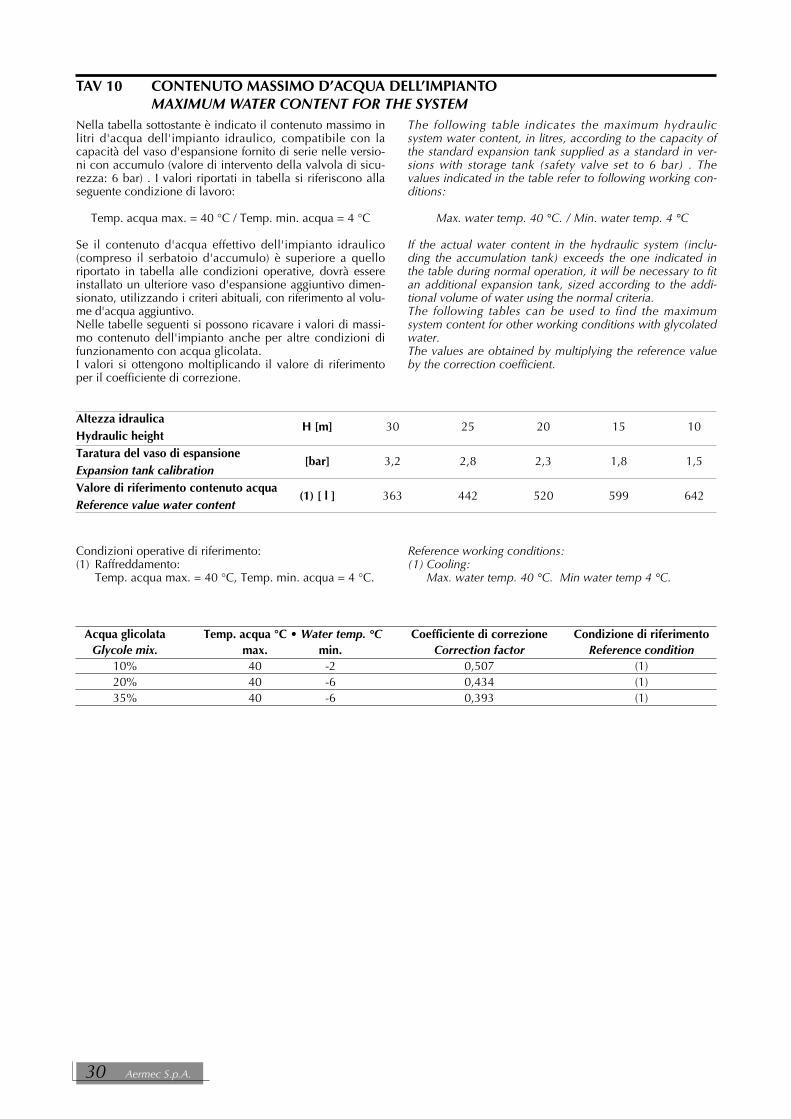
TAV 10 CONTENUTO MASSIMO D’ACQUA DELL’IMPIANTOMAXIMUM WATER CONTENT FOR THE SYSTEM
Altezza idraulicaH [m] 30 25 20 15 10
Hydraulic heightTaratura del vaso di espansione
[bar] 3,2 2,8 2,3 1,8 1,5Expansion tank calibrationValore di riferimento contenuto acqua
(1) [ l ] 363 442 520 599 642Reference value water content
Condizioni operative di riferimento:(1) Raffreddamento:
Temp. acqua max. = 40 °C, Temp. min. acqua = 4 °C.
Reference working conditions:(1) Cooling:
Max. water temp. 40 °C. Min water temp 4 °C.
Acqua glicolata Temp. acqua °C • Water temp. °C Coefficiente di correzione Condizione di riferimentoGlycole mix. max. min. Correction factor Reference condition
10% 40 -2 0,507 (1)20% 40 -6 0,434 (1)35% 40 -6 0,393 (1)
Nella tabella sottostante è indicato il contenuto massimo inlitri d'acqua dell'impianto idraulico, compatibile con lacapacità del vaso d'espansione fornito di serie nelle versio-ni con accumulo (valore di intervento della valvola di sicu-rezza: 6 bar) . I valori riportati in tabella si riferiscono allaseguente condizione di lavoro:
Temp. acqua max. = 40 °C / Temp. min. acqua = 4 °C
Se il contenuto d'acqua effettivo dell'impianto idraulico(compreso il serbatoio d'accumulo) è superiore a quelloriportato in tabella alle condizioni operative, dovrà essereinstallato un ulteriore vaso d'espansione aggiuntivo dimen-sionato, utilizzando i criteri abituali, con riferimento al volu-me d'acqua aggiuntivo.Nelle tabelle seguenti si possono ricavare i valori di massi-mo contenuto dell'impianto anche per altre condizioni difunzionamento con acqua glicolata.I valori si ottengono moltiplicando il valore di riferimentoper il coefficiente di correzione.
The following table indicates the maximum hydraulicsystem water content, in litres, according to the capacity ofthe standard expansion tank supplied as a standard in ver-sions with storage tank (safety valve set to 6 bar) . Thevalues indicated in the table refer to following working con-ditions:
Max. water temp. 40 °C. / Min. water temp. 4 °C
If the actual water content in the hydraulic system (inclu-ding the accumulation tank) exceeds the one indicated inthe table during normal operation, it will be necessary to fitan additional expansion tank, sized according to the addi-tional volume of water using the normal criteria.The following tables can be used to find the maximumsystem content for other working conditions with glycolatedwater.The values are obtained by multiplying the reference valueby the correction coefficient.
30 Aermec S.p.A.

��� !������
����������
��"#!!
�
Il valore standard di pressione di precarica del vasod’espansione è pari a 1,5 bar, mentre il suo volume è di 8litri.La taratura del vaso dev’ esssere regolata in funzione delmassimo dislivello (H) dell’utilizzatore (vedi figura) secon-do la formula:
p (taratura) [bar] = H [m] / 10,2 + 0,3.Ad esempio se il valore del dislivello H è pari a 20 m, ilvalore di taratura del vaso sarà 2,3 bar. Se il valore di taratura ricavato dal calcolo risultasse inferio-re a 1,5 bar (cioè per H < 12,25), mantenere la taraturastandard.
The standard expansion tank pre-charge pressure value is1,5 bar, it contains 24 l.The tank must be calibrated according to the maximum dif-ference in level (H) with respect to the user (see figure),applying the formula:
p (calibration) [bar] = H [m] / 10,2 + 0,3.For example, if the difference in level H is 20 m, the tankcalibration value will be 2,3 bar. If the calibration value obtained is lower than 1,5 bar (thatis to say H < 12,25), the standard calibration should bemaintained.
TARATURA DEL VASO D’ESPANSIONE • EXPANSION TANK CALIBRATION
* Verificare che l’utilizzatore più alto non superi i 55metri di dislivello.
** Verificare che l’utilizzatore più basso possa sopportare la pressione globale agente in quel punto.
* Ensure that the highest terminal unit doesn’t exceed 55metres of level difference.
** Ensure that the lowest terminal unit can support the global pressure present at that point.
NRA Fc Cod. 6871970_00 31

�
��
���
���
���
���
� � �� �� �� �� �� ��
�
� � � � �
�
�
�
���
�
��
���
���
���
���
� � �� �� �� �� �� �� ��
�
�� � � � �
�
�
���
TAV 12 PREVALENZA UTILE CON FREE-COOLING WORKING HEAD WITH FREE-COOLING
TAV 11 PREVALENZA UTILE SENZA FREE-COOLING WORKING HEAD WITHOUT FREE-COOLING
Portata acqua • Water flow
Portata acqua • Water flow
A = 275B = 300C = 325 - 350D = 500E = 550F = 600G = 650H = 700
Le prestazioni sono riferite alle seguenti condizioni:❄ -temperatura acqua prodotta = 7 °C;
Performances refer to following conditions:❆ temperature of processed water = 7 °C;
A = 275B = 300C = 325 - 350D = 500E = 550F = 600G = 650H = 700
Le portate d'acqua per ogni taglia di macchina devono esse-re comprese tra i seguenti valori minimi e massimi:0,5xQn <Q<1,67xQndove Qn è la portata nominale
The water flow rates for each machine size must be betweenthe following minimum and maximum values:0,5xQn <Q<1,67xQnwhere Qn is the nominal flow rate
32 Aermec S.p.A.

TAV 13 PRESSIONE E POTENZA SONORA espressa in dB(A) - MODALITÀ REFRIGERATORE SOUND PRESSURE AND POWER LEVEL rated in dB(A) - CHILLER MODE
Pressione sonora* Potenza sonora per frequenza centrale di banda (Hz) globaleSound pressure* Sound power band middle frequency (Hz) total
Mod. 125 250 500 1.000 2.000 4.000 8.000dB(A) dB dB dB dB dB dB dB dB dB (A)
NRA F 275 A 48,0 76,6 76,5 73,5 71,5 66,3 61,5 51,0 81,2 76,0NRA F 275 L 48,0 77,2 77,0 74,1 71,2 66,1 59,2 49,5 81,7 76,0
NRA F 300 A 48,0 77,6 74,9 74,5 71,5 66,0 59,7 49,7 81,3 76,0NRA F 300 L 48,0 77,7 74,9 74,1 71,7 66,6 59,7 50,0 81,3 76,0
NRA F 325 A 49,0 77,5 77,8 76,1 71,4 66,8 59,7 50,3 82,5 77,0NRA F 325 L 49,0 79,8 78,0 75,8 71,4 66,6 60,0 50,8 83,3 77,0
NRA F 350 A 49,0 79,1 77,5 75,5 72,0 66,9 59,5 49,3 82,9 77,0NRA F 350 L 49,0 79,3 77,3 75,5 72,0 67,0 59,8 49,6 82,9 77,0
NRA F 500 ° 54,5 84,2 78,6 77,5 77,2 76,3 73,2 64,3 87,1 82,5NRA F 500 A 54,5 84,2 78,6 77,5 77,2 76,3 73,2 64,3 87,1 82,5NRA F 500 L 46,0 77,2 72,3 70,1 69,0 66,8 62,3 53,8 79,7 74,0
NRA F 550 ° 54,5 84,1 78,4 77,9 77,6 76,5 71,2 62,3 87,0 82,5NRA F 550 A 54,5 84,1 78,4 77,9 77,6 76,5 71,2 62,3 87,0 82,5NRA F 550 L 46,5 78,9 73,1 70,7 69,4 67,1 62,6 54,0 81,0 74,5
NRA F 600 ° 55,0 85,6 78,8 78,4 78,0 77,0 72,1 63,0 88,1 83,0NRA F 600 A 55,0 85,6 78,8 78,4 78,0 77,0 72,1 63,0 88,1 83,0NRA F 600 L 49,0 81,5 79,8 74,3 70,1 68,0 62,1 53,9 84,5 77,0
NRA F 650 ° 56,0 86,7 80,7 79,5 78,5 77,8 73,9 63,5 89,2 84,0NRA F 650 A 56,0 86,7 80,7 79,5 78,5 77,8 73,9 63,5 89,2 84,0NRA F 650 L 49,0 82,1 74,7 73,9 72,3 69,2 63,0 55,3 83,9 77,0
NRA F 700 ° 56,0 83,8 79,9 79,7 79,5 77,4 72,9 64,7 87,8 84,0NRA F 700 A 56,0 83,8 79,9 79,7 79,5 77,4 72,9 64,7 87,8 84,0NRA F 700 L 49,0 82,0 76,5 74,6 72,3 68,3 62,1 53,8 84,1 77,0
I dati riportati esprimono la potenza sonora totale emessa dalla macchina alle condizioni nominali di funzionamento in raf-freddamento.* = Pressione sonora in campo libero a 10 m di distanza, con fattore di direzionalità 2.
The data given the total sound power level ratings of the unit at nominal operating conditions in cooling.* = sound pressure in free field conditions at a distance of 10 m with a directional factor of 2.
DATI SONORI • SOUND DATA
NRA Fc Cod. 6871970_00 33

TAV 14 PRESSIONE E POTENZA SONORA espressa in dB(A) - MODALITÀ FREE-COOLING SOUND PRESSURE AND POWER LEVEL rated in dB(A) - FREE-COOLING MODE
Pressione sonora* Potenza sonora per frequenza centrale di banda (Hz) globaleSound pressure* Sound power band middle frequency (Hz) total
Mod. 125 250 500 1.000 2.000 4.000 8.000dB(A) dB dB dB dB dB dB dB dB dB (A)
NRA F 275 46,0 76,2 73,1 72,3 69,9 63,3 55,6 47,6 79,6 74,0
NRA F 300 46,0 76,2 73,1 72,3 69,9 63,3 55,6 47,6 79,6 74,0
NRA F 325 47,0 77,2 74,1 73,3 70,9 64,3 56,6 48,6 80,6 75,0
NRA F 350 47,0 77,2 74,1 73,3 70,9 64,3 56,6 48,6 80,6 75,0
NRA F 500 50,0 82,9 76,9 72,4 73,4 70,5 66,7 58,0 84,8 78,0
NRA F 550 50,0 82,9 76,9 72,4 73,4 70,5 66,7 58,0 84,8 78,0
NRA F 600 52,0 85,0 79,0 74,5 75,5 72,6 68,8 60,1 86,8 80,0
NRA F 650 52,0 85,0 79,0 74,5 75,5 72,6 68,8 60,1 86,8 80,0
NRA F 700 52,0 85,0 79,0 74,5 75,5 72,6 68,8 60,1 86,8 80,0
I dati riportati esprimono la potenza sonora totale emessa dalla macchina alle condizioni nominali di funzionamento in raf-freddamento.* = Pressione sonora in campo libero a 10 m di distanza, con fattore di direzionalità 2.
The data given the total sound power level ratings of the unit at nominal operating conditions in cooling.* = sound pressure in free field conditions at a distance of 10 m with a directional factor of 2.
TAV 15 PARZIALIZZAZIONE • CAPACITY CONTROLPotenza frigorifera % Gradini di parzializzazioneCooling Capacity % Capacity step
1° 2° 3° 4°275 • 325 • 350 50 100300 57/43 100500 39 78 100550 38 76 100600 • 650 • 700 30 61 80 100
Potenza termica % Gradini di parzializzazioneHeating Capacity % Capacity step
1° 2° 3° 4°275 •325 • 350 50 100300 57/43 100500 37 75 100550 36 73 100600 • 650 • 700 28 56 78 100
Potenza assorbita % Gradini di parzializzazioneInput power % Capacity step
1° 2° 3° 4°275 • 325 • 350 50 100300 57/43 100500 34 67 100550 31 66 100600 • 650 • 700 22 43 72 100
34 Aermec S.p.A.

TAV 16 CAMPO DI TARATURA DEI PARAMETRI DI CONTROLLOCONTROL PARAMETER SETTING RANGE
min. standard max.Set point raffreddamento • Cooling set point [°C] 4 (– 10)* 7 (-10)* 14Intervento antigelo • Antifreeze set point [°C] – 9 3 4Differenziale totale • Total differential [°C] 3 5 10Autostart -- Auto --
* = Versione Y • Y Version
TAV 17 TARATURA DISPOSITIVI DI PROTEZIONE • PROTECTION DEVICE SETTINGSMod. 275 300 325 350 500 550 600 650 700
(°) - - - - 6 6 6 6 6Magnetotermico ventilatori A 4 6 6 8 6 6 6 6 9Fan circuit breaker
[A]L 4 6 6 6 6 6 6 9 9
Magnetotermico compressore2x25 25-30 2x30 2x35 2x25-35 25-30-35 25-30-25-30 4 x 30 4 x 35
Compressor circuit breaker [A]
Pressostato alta pressione[bar] 28 28 28 28 28 28 28 28 28
High pressure switchTrasduttore bassa pressione
[bar] 1 1 1 1 1 1 1 1 1Low pressure trasducerResistenze carter
[n° x W] 2 x 75 2 x 75 2 x 75 2 x 75 3 x 75 3 x 75 4 x 75 4 x 75 4 x 75Crankcases heater
TARATURE DISPOSITIVI DI PROTEZIONE • PROTECTION DEVICE SETTINGS
TARATURA DEL FLUSSOSTATOTutti i flussostati presenti nelle unità NRA sono già tarati infabbrica per un corretto funzionamento con portata d’acquanominale: tale taratura viene effettuata per una portata cor-rispondente al 75% della portata nominale (con un differen-ziale di temperatura di 5°C), questo consente nella stragran-de maggioranza dei casi di non dover ricorrere ad operazio-ni aggiuntive. Qualora comunque si intendesse operare con portated’acqua inferiori di oltre il 20% a quelle nominali, sidovranno eseguire le seguenti operazioni di taratura:1)avviare l’unità e portarla a regime;2) leggere sul display del pannello comandi il valore del dif-
ferenziale temperatura acqua tra ingresso e uscita;3)chiudere lentamente la valvola manuale d’intercettazione
di uscita, fino ad ottenere un incremento di circa 1,25volte il valore del differenziale di temperatura (∆∆ t) lettoprecedentemente;
4)agendo sull’apposita vite tarare il flussostato fino al suointervento;
5) riaprire completamente la valvola manuale d’intercetta-zione di uscita.
SETTING OF FLOW SWITCHAll the flow switches in NRA units are already factory set for
correct operation with nominal water flow rate: this set-ting is made for a flow rate corresponding to 75% of thenominal flow rate (with a temperature difference of 5°C).
In the vast majority of cases this means that no additionaloperations are necessary.
1)start the unit and bring it up to normal operating condi-tions;
2)read the control panel display, indicating the differencein water temperature for incoming and outgoing water;
3)slowly close the manual output cut-out valve, until the dif-ference in temperature read as above increases byapproximately 1°C;
4)turn the screw provided to adjust the flow switch until ittriggers;
5)open up the manual output cut-out valve again
NRA Fc Cod. 6871970_00 35
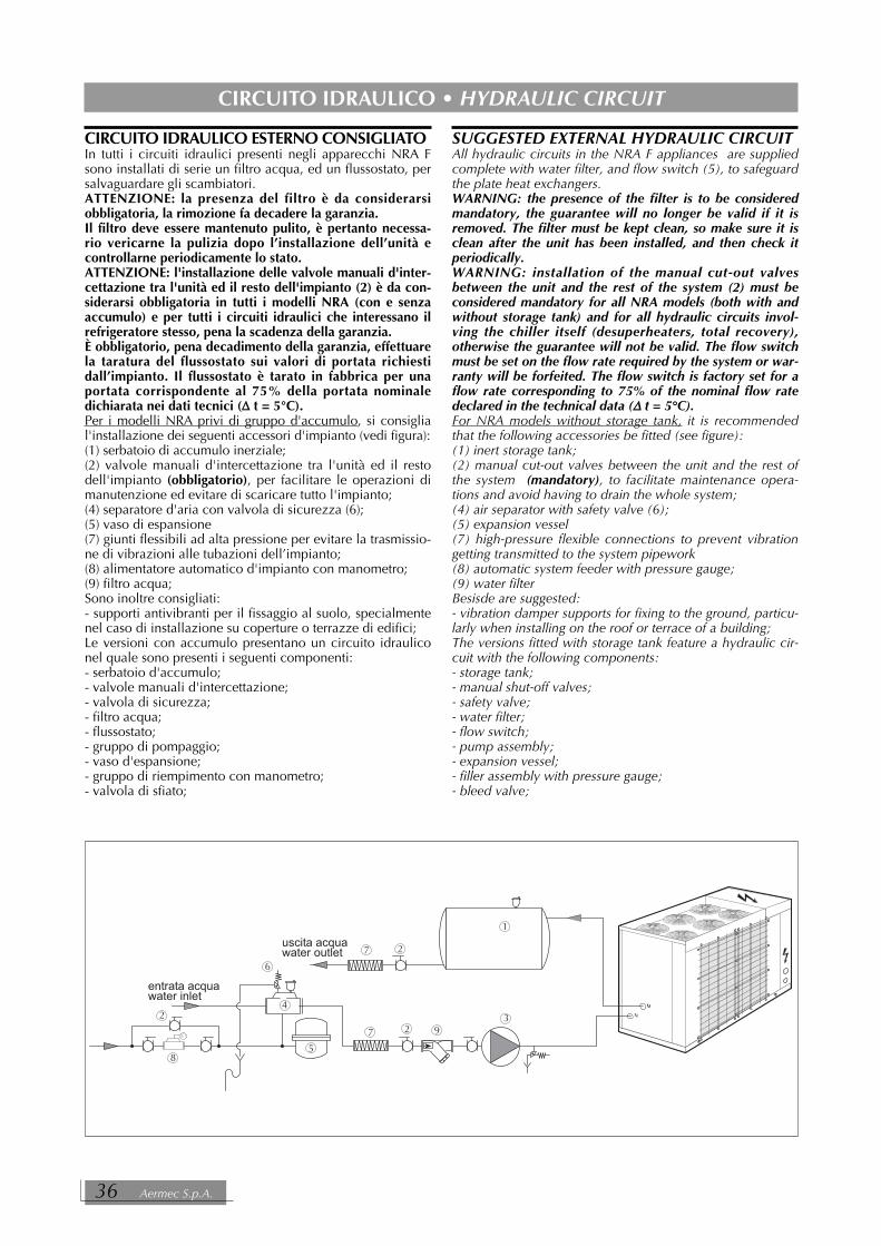
CIRCUITO IDRAULICO ESTERNO CONSIGLIATOIn tutti i circuiti idraulici presenti negli apparecchi NRA Fsono installati di serie un filtro acqua, ed un flussostato, persalvaguardare gli scambiatori. ATTENZIONE: la presenza del filtro è da considerarsiobbligatoria, la rimozione fa decadere la garanzia.Il filtro deve essere mantenuto pulito, è pertanto necessa-rio vericarne la pulizia dopo l’installazione dell’unità econtrollarne periodicamente lo stato. ATTENZIONE: l'installazione delle valvole manuali d'inter-cettazione tra l'unità ed il resto dell'impianto (2) è da con-siderarsi obbligatoria in tutti i modelli NRA (con e senzaaccumulo) e per tutti i circuiti idraulici che interessano ilrefrigeratore stesso, pena la scadenza della garanzia.È obbligatorio, pena decadimento della garanzia, effettuarela taratura del flussostato sui valori di portata richiestidall’impianto. Il flussostato è tarato in fabbrica per unaportata corrispondente al 75% della portata nominaledichiarata nei dati tecnici (∆∆ t = 5°C).Per i modelli NRA privi di gruppo d'accumulo, si consiglial'installazione dei seguenti accessori d'impianto (vedi figura):(1) serbatoio di accumulo inerziale;(2) valvole manuali d'intercettazione tra l'unità ed il restodell'impianto (obbligatorio), per facilitare le operazioni dimanutenzione ed evitare di scaricare tutto l'impianto;(4) separatore d'aria con valvola di sicurezza (6);(5) vaso di espansione(7) giunti flessibili ad alta pressione per evitare la trasmissio-ne di vibrazioni alle tubazioni dell’impianto;(8) alimentatore automatico d'impianto con manometro;(9) filtro acqua;Sono inoltre consigliati:- supporti antivibranti per il fissaggio al suolo, specialmentenel caso di installazione su coperture o terrazze di edifici;Le versioni con accumulo presentano un circuito idrauliconel quale sono presenti i seguenti componenti:- serbatoio d'accumulo;- valvole manuali d'intercettazione;- valvola di sicurezza;- filtro acqua;- flussostato;- gruppo di pompaggio;- vaso d'espansione;- gruppo di riempimento con manometro;- valvola di sfiato;
SUGGESTED EXTERNAL HYDRAULIC CIRCUITAll hydraulic circuits in the NRA F appliances are suppliedcomplete with water filter, and flow switch (5), to safeguardthe plate heat exchangers. WARNING: the presence of the filter is to be consideredmandatory, the guarantee will no longer be valid if it isremoved. The filter must be kept clean, so make sure it isclean after the unit has been installed, and then check itperiodically. WARNING: installation of the manual cut-out valvesbetween the unit and the rest of the system (2) must beconsidered mandatory for all NRA models (both with andwithout storage tank) and for all hydraulic circuits invol-ving the chiller itself (desuperheaters, total recovery),otherwise the guarantee will not be valid. The flow switchmust be set on the flow rate required by the system or war-ranty will be forfeited. The flow switch is factory set for aflow rate corresponding to 75% of the nominal flow ratedeclared in the technical data (∆∆ t = 5°C).For NRA models without storage tank, it is recommendedthat the following accessories be fitted (see figure):(1) inert storage tank;(2) manual cut-out valves between the unit and the rest ofthe system (mandatory), to facilitate maintenance opera-tions and avoid having to drain the whole system;(4) air separator with safety valve (6);(5) expansion vessel(7) high-pressure flexible connections to prevent vibrationgetting transmitted to the system pipework(8) automatic system feeder with pressure gauge;(9) water filterBesisde are suggested:- vibration damper supports for fixing to the ground, particu-larly when installing on the roof or terrace of a building;The versions fitted with storage tank feature a hydraulic cir-cuit with the following components:- storage tank;- manual shut-off valves;- safety valve;- water filter;- flow switch;- pump assembly;- expansion vessel;- filler assembly with pressure gauge;- bleed valve;
�
�
�
�
�
��
�
��
�
������������������������
������������������������
CIRCUITO IDRAULICO • HYDRAULIC CIRCUIT
36 Aermec S.p.A.

LEGENDA PER CIRCUITO IDRAULICO NRA• KEY FOR NRA HYDRAULIC CIRCUITACC = Serbatoio accumulo • Liquid receiverFC = Batteria acqua - aria • Water to air heat exchangerFL = Flussostato • Flow switchFM = Filtro acqua • Water filterMPO= Pompa acqua • Water pumpSIW = Sonda temperatura ingresso acqua • Water inlet temperature probe SUW= Sonda temperatura uscita acqua • Water outlet temperature probe SW-inev=Sonda temperatura ingresso evaporatore • Water inlet temperature probe (evaporator)SW-out =Sonda temperatura uscita acqua • Water outlet temperature probe EV = Evaporatore a piastre• Evaporator plate exchangerGCR = Gruppo di caricamento con manometro • Water makeup group with pressure gaugeV = Ventilatore • FanVESP = Vaso di espansione • Expansion tankV3V = Valvola 3 vie motorizzata • Motorized 3-way valveVSF = Separatore d’aria con valvola di sfiato automatica • Air separator with automatic air ventVSA = Valvola scarico acqua • Water discharge valveVSIC = Valvola di sicurezza • Safety valve
��%
�& '$(')�"#*+
��,
')�-./
%�%
%
�0
%
'1(
$�
,12
������������
������������
��%
�&'$(')�"#*+
��,
')�-./
%�%
%
�0'1(
&3,
���
$�
,12
���
%�'3%'$�
%'�
%'�
������������
������������
CIRCUITO IDRAULICO INTERNODi seguito viene schematizzato il circuito idraulico internoalla macchina per entrambe le versioni: con e senza accu-mulo.
INSIDE HYDRAULIC CIRCUITBelow you can find the diagram referred to the unit watercircuit for both versions : with and without storage tank.
Mod. NRA F0
Mod. NRA F3
NRA Fc Cod. 6871970_00 37

ATTACCHI IDRAULICI:HYDRAULIC COUPLINGS:
D = gruppo caricamento (1/2” Gas)loading unit (1/2” Gas)
M = Uscita acqua • Water outputFemmina • Female (2”1/2 Gas)
N = Ingresso acqua • Water inputFemmina • Female (2”1/2 Gas)
��
��
�
DIMENSIONI E POSIZIONE ATTACCHI • DIMENSIONS AND POSITION OF CONNECTIONS [mm]
����
���
��
�����
�
�
�
Mod. NRA F0 / F3/ F4275 - 300 - 325 - 350 L /A
38 Aermec S.p.A.

DIMENSIONI E POSIZIONE ATTACCHI • DIMENSIONS AND POSITION OF CONNECTIONS [mm]
�
����
���
��
�����
�
&
�
�0
����
���
��
�����
�
&
Mod. NRA F600 - 650 - 700 (°) - A - L
Mod. NRA F500 - 550 (°) - A - L
NRA Fc Cod. 6871970_00 39

��% ��,
%
%
��
�
������������
�3
%'
%'
�23�
�3
�23�
�3
%'
�23�
�3
�23�
%'
��
$�0
%2
%1
%'
%1
%1
%1
%1
%'
��
$�0
%2
%'
%'
%1
%1
%'
%1
%'
������������
��
�
LEGENDA PER CIRCUITO FRIGORIFERO • KEY FOR COOLING CIRCUIT
AL = Serbatoio accumulo • Liquid receiverAP = Pressostato di alta • High pressure switchCN = Scambiatore lato aria • Heat exchanger air sideCP = Compressore • CompressorEV = Evaporatore • EvaporatorFC = Batteria acqua - aria • Water to air heat exchangerFD = Filtro deidratatore • Dehumidifier filterIDL = Indicatore di liquido • Sight glassMPO= Pompa acqua • Water pumpTP1 = Trasduttore di bassa pressione • Low pressure transducerTP2 = Trasduttore di alta pressione • High pressure transducerV = Ventilatore • FanVS = Valvola solenoide • Solenoid valveVSIC = Valvola di sicurezza • Safety valveVT = Valvola termostatica • Thermostatic valveVU = Valvola unidirezionale • Unidirectional valve
Mod. NRA F0 - F3 -F4
LAY-OUT CIRCUITO FRIGORIFERO E DISPOSITIVI DI CONTROLLOCOOLING CIRCUIT LAY-OUT AND CONTROL DEVICES
CIRCUITO FRIGORIFERO • CHILLER CIRCUIT
40 Aermec S.p.A.

����
����
��� ���
���
����
�
ATTACCHI ELETTRICI:ELECTRIC CONNECTIONS:EL= ingresso alimentazione elettrica
(disponibile a destra e a sinistra)electric power inlet(available on right and left sides)
DIMENSIONI • DIMENSIONS [mm]
Mod. NRA F0 - F3-F4275 - 300 - 325 - 350 L /A
0
��
��� ���
���
�0
����
Mod. NRA F0 L500 - 550 (°) - A - L 2950
Mod. NRA F3 - F4 con accumulo•with storage tank L500 - 550 (°) - A - L 3200
DATI DIMENSIONALI • DIMENSIONS
NRA Fc Cod. 6871970_00 41

DIMENSIONI • DIMENSIONS [mm]
����
��
��� ���
���
�
�0
����
�
&
Mod. NRA F0 - F3-F4600 - 650 - 700 (°) - A - L
32
130
76
PANNELLO DI COMANDO A DISTANZAREMOTE CONTROL PANEL
42 Aermec S.p.A.

VERSIONE BASE (°) • STANDARD VERSION (°)SENZA ACCUMULO • WITHOUT STORAGE TANKGrandezza • Size 500 550 600 650 700Peso • Weight [kg] 1.225 1.250 1.435 1.550 1.600
Gx [mm] 1.335 1.325 1.670 1.675 1.640Gy [mm] 560 560 550 550 550A % 26 26 29 29 29B % 27 27 29 29 29C % 23 23 21 21 21D % 24 24 21 21 21
CON ACCUMULO VUOTO • WITH EMPTY STORAGE TANKGrandezza • Size 500 550 600 650 700Peso • Weight [kg] 1.365 1.390 1.555 1.670 1.720
Gx [mm] 1.403 1.393 1.684 1.688 1.655Gy [mm] 560 560 550 550 550
CON ACCUMULO PIENO D’ACQUA (300 litri) • WITH FULL STORAGE TANK (300 litres)Grandezza • Size 500 550 600 650 700Peso • Weight [kg] 1.740 1.765 1.930 2.055 2.105
Gx [mm] 1.532 1.522 1.716 1.718 1.690Gy [mm] 560 560 550 550 550A % 26 26 9 9 9B % 26 26 9 9 9C % 24 24 12 12 12D % 24 24 12 12 12E % - - 29 29 29F % - - 29 29 29
VERSIONE SILENZIATA (L) • LOW NOISE VERSIONS (L)SENZA ACCUMULO • WITHOUT STORAGE TANKGrandezza • Size 275 300 325 350 500 550 600 650 700Peso • Weight [kg] 855 975 990 1.030 1.245 1.295 1.545 1.660 1.710
Gx [mm] 1.090 1.125 1.100 1.075 1.325 1.325 1.695 1.700 1.665Gy [mm] 550 550 550 550 565 560 550 550 550A % 32 32 32 32 26 27 28 28 29B % 32 32 32 32 28 27 28 28 29C % 18 18 18 18 22 23 22 22 21D % 18 18 18 18 24 23 22 22 21
CON ACCUMULO VUOTO • WITH EMPTY STORAGE TANKGrandezza • Size 275 300 325 350 500 550 600 650 700Peso • Weight [kg] 975 1.095 1.110 1.150 1.385 1.435 1.665 1.780 1.830
Gx [mm] 1.147 1.172 1.149 1.125 1.393 1.391 1.706 1.710 1.677Gy [mm] 550 550 550 550 565 560 550 550 550
CON ACCUMULO PIENO D’ACQUA (300 litri) • WITH FULL STORAGE TANK (300 litres)Grandezza • Size 275 300 325 350 500 550 600 650 700Peso • Weight [kg] 1.315 1.445 1.460 1.500 1.760 1.810 2.040 2.165 2.215
Gx [mm] 1.251 1.263 1.245 1.224 1.523 1.517 1.733 1.735 1.707Gy [mm] 550 550 550 550 565 560 550 550 550A % 29 29 29 29 26 26 9 9 9B % 29 29 29 29 26 26 9 9 9C % 21 21 21 21 24 24 12 12 12D % 21 21 21 21 24 24 12 12 12E % - - - - - - 29 29 29F % - - - - - - 29 29 29
PESI [kg], BARICENTRO [mm] e DISTRIBUZIONE PERCENTUALE DEL PESO SUGLI APPOGGIWEIGHTS [kg], CENTER OF GRAVITY [mm] and PERCENTAGE DISTRIBUTION OF WEIGHT ON SUPPORTS
NRA Fc Cod. 6871970_00 43

VERSIONE ALTA TEMPERATURA (A) • HIGH TEMPERATURE VERSION (A)
SENZA ACCUMULO • WITHOUT STORAGE TANKGrandezza • Size 275 300 325 350 500 550 600 650 700Peso • Weight [kg] 915 1.035 1.050 1.090 1.245 1.295 1.545 1.660 1.710
Gx [mm] 1.135 1.165 1.140 1.115 1.325 1.325 1.695 1.700 1.665Gy [mm] 550 550 550 550 565 560 550 550 550A % 32 32 32 32 26 27 28 28 29B % 32 32 32 32 28 27 28 28 29C % 18 18 18 18 22 23 22 22 21D % 18 18 18 18 24 23 22 22 21
CON ACCUMULO VUOTO • WITH EMPTY STORAGE TANKGrandezza • Size 275 300 325 350 500 550 600 650 700Peso • Weight [kg] 1.035 1.155 1.170 1.210 1.385 1.435 1.665 1.780 1.830
Gx [mm] 1.183 1.205 1.182 1.158 1.393 1.391 1.706 1.710 1.677Gy [mm] 550 550 550 550 565 560 550 550 550
CON ACCUMULO PIENO D’ACQUA (300 litri) • WITH FULL STORAGE TANK (300 litres)Grandezza • Size 275 300 325 350 500 550 600 650 700Peso • Weight [kg] 1.375 1.505 1.520 1.560 1.760 1.810 2.040 2.165 2.215
Gx [mm] 1.274 1.285 1.267 1.246 1.523 1.517 1.733 1.735 1.707Gy [mm] 550 550 550 550 565 560 550 550 550A % 29 29 29 29 26 26 9 9 9B % 29 29 29 29 26 26 9 9 9C % 21 21 21 21 24 24 12 12 12D % 21 21 21 21 24 24 12 12 12E % - - - - - - 29 29 29F % - - - - - - 29 29 29
PESI [kg], BARICENTRO [mm] e DISTRIBUZIONE PERCENTUALE DEL PESO SUGLI APPOGGIWEIGHTS [kg], CENTER OF GRAVITY [mm] and PERCENTAGE DISTRIBUTION OF WEIGHT ON SUPPORTS
44 Aermec S.p.A.

����
�
���� �
������
� �
����
�
���� �
������
� �
����
��
���� �
������ ����
�� �
�
�4
Baricentro • Center of gravity
BARICENTRO E PUNTI DI APPOGGIO
CENTER OF GRAVITY AND SUPPORTS
Mod. NRA F0 / F3-F4500 - 550 (°) - A - L
Mod. NRA F0 / F3-F4275 - 300 - 325 - 350 L /A
Le dimensioni sono riferite al basamento delle unità • Dimensions refer to the basement
Mod. NRA F0 / F3-F4600 - 650 - 700 (°) - A - L
NRA Fc Cod. 6871970_00 45

%2
��
5��
��
���
���
� �
��
��
5��
��
���
���
� �
��
DATI ACCESSORI • ACCESSORIES DATA [mm]
%2��
5��
��
���
���
����
� �
��
� �
SUPPORTI ANTIVIBRANTI - VTANTIVIBRATION PAD - VT
Mod. NRA 275 A - L NRA 300 A - L NRA 325 A - L NRA 350 A - LNRA 500 (°) - A - L NRA 550 (°) - A - L NRA 600 (°) - A - L NRA 650 (°) - A - L NRA 700 (°) - A - L
Mod. (**)NRA 600 (°) - A - L NRA 650 (°) - A - L NRA 700 (°) - A - L
�
� n° A B C
VT 10 4 155 95 M14 Nero • Black VT 11 6 155 95 M14 Nero • Black VT 13 4 135 81 M14 Nero • Black VT 14 2 135 81 M14 Nero • Black
2 155 95 M14 Nero • Black
** = Nei modelli con accumulo •In models with storage tank.
46 Aermec S.p.A.

MOVIMENTAZIONEAl ricevimento dell’unità accertarsi che non abbia subitodanni durante il trasporto.Prima di movimentare l’unità prendere visione delle dimen-sioni, pesi, baricentro e punti di sollevamento, quindi verifi-care che le attrezzature per il sollevamento e posiziona-mento siano adeguate e rispettino le norme di sicurezzavigenti.Particolare attenzione va posta a tutte le operazioni di cari-co, scarico e sollevamento onde evitare situazioni di perico-lo per le persone, danneggiamenti alla carpenteria ed agliorgani funzionali della macchina.E’ assolutamente vietato depositare oggetti sopra l’unità.Il personale addetto alla movimentazione deve essere prov-visto di adeguati mezzi di protezione individuale.É assolutamente vietato sostare sotto l‘unità.
- Il diametro dei fori del basamento da utilizzare per il solle-vamento misura 40 mm. - I pali di sollevamento, vanno dimensionati adeguatamente ein modo da sporgere dal basamento per una lunghezza taleche le funi di sollevamento possano essere tese verso l’altosenza incontrare interferenze; le estremità dei pali devono esse-re provviste di elementi di sicurezza che impediscano alle funidi sfilarsi.- Accertarsi che le funi sianoomologate per sopportare ilpeso dell’unità, fare atten-zione che siano ben fissate.- Il telaio di sollevamentodeve avere il punto diaggancio sulla verticaledel baricentro, gli assi delbaricentro sono indicati daetichette adesive poste sulbasamento.Durante il sollevamento siconsiglia di montare i sup-porti antivibranti, fissandoliai fori Ø18mm del basa-mento, secondo lo schemadi montaggio a corredodegli accessori (VT).
HANDLINGOn receiving the unit, make sure that it has not suffered anydamage during transport.Before moving the unit, check its dimensions, weight, centreof gravity and lifting points, then make sure that the liftingand positioning equipment to be used is adequate and thatit complies with current safety regulations.Particular care must be taken during all loading, unloadingand lifting operations, to avoid potential danger to persons,damage to carpentry works and damage to the machine'sworking parts.Never place objects of any kind on top of the unit.Staff involved in moving the appliance must be equippedwith suitable personal protection equipment.Never stand under the unit.
- The diameter of the holes in the base to be used when lif-ting is 40 mm. - The lifting forks must be of a suitable size, and must protru-de from the base by a length sufficient to allow the liftingcables to be raised from above without encountering anytype of interference; the ends of the forks must be fittedwith safety devices to prevent the cables from sliding off.
- Make sure that the cablesare capable of bearing thefull weight of the unit, andensure they are firmly fixed.- The lifting frame connec-tion point must be verticalto the centre of gravity, theaxes of the centre of gravityare indicated by adhesivelabels on the base itself.
During lifting it is recom-mended that the vibrationdamper supports be instal-led, f itt ing them to theØ18mm holes in the base,according to the assemblydiagram supplied with theaccessories (VT).
INSTALLAZIONE E UTILIZZO DELL’UNITÀ • UNIT INSTALLATION AND USE
SPEDIZIONELe macchine NRA vengono spedite su un pallet di legno. A protezione delle batterie vengono posti dei pannelli inpolistirolo.L’unità inoltre al fine di evitare graffiature viene avvolta inpiù strati di un film estensibile in polietilene.
DELIVERYNRA units are despatched on wooden pallets.Polystyrene panels are placed to protect the coils.In order not to be scratched the unit is wrapped several timesin a polyethylene extendible film.
NRA Fc Cod. 6871970_00 47

SPAZI TECNICI MINIMI • MINIMUM TECHNICAL CLEARANCES [mm]
����
���
���
����
���
UBICAZIONELe macchine della serie NRA devono essere installate all'e-sterno, in zona adeguata. Pertanto dovrà essere installataprevedendo gli spazi tecnici necessari (vedi "Dati dimensio-nali"). Questo è indispensabile sia per consentire gli inter-venti di ordinaria e straordinaria manutenzione che per esi-genze di funzionamento, dovendo l'apparecchio raccoglie-re aria dall'esterno lungo i lati perimetrali ed espellerlaverso l'alto. Per il corretto funzionamento dell'unità, essadovrà essere installata su di un piano perfettamente orizzon-tale. Assicurarsi che il piano di appoggio sia in grado disupportare il peso della macchina.L'apparecchio è realizzato in lamiera di acciaio zincata etrattata mediante verniciatura a caldo con polveri poliureta-niche per resistere alle intemperie. Non sono pertantonecessari particolari accorgimenti per la protezione dell'u-nità. Si consiglia, invece, se è prevista la possibilità di gran-dinate, di proteggere le batterie condensanti con una prote-zione antigrandine.In caso di posizionamento della macchina in zone partico-larmente ventose occorre prevedere delle barriere frangi-vento per evitare un funzionamento instabile del dispositivoDCPX.
POSITIONINGLe macchine della serie NRA devono essere installate all'e-sterno, in zona adeguata. Pertanto dovrà essere installataprevedendo gli spazi tecnici necessari (vedi "Dati dimensio-nali"). Questo è indispensabile sia per consentire gli inter-venti di ordinaria e straordinaria manutenzione che per esi-genze di funzionamento, dovendo l'apparecchio raccoglierearia dall'esterno lungo i lati perimetrali ed espellerla versol'alto. Per il corretto funzionamento dell'unità, essa dovràessere installata su di un piano perfettamente orizzontale.Assicurarsi che il piano di appoggio sia in grado di supporta-re il peso della macchina.L'apparecchio è realizzato in lamiera di acciaio zincata etrattata mediante verniciatura a caldo con polveri poliureta-niche per resistere alle intemperie. Non sono pertantonecessari particolari accorgimenti per la protezione dell'u-nità. Si consiglia, invece, se è prevista la possibilità di gran-dinate, di proteggere le batterie condensanti con una prote-zione antigrandine.Should the unit be positioned in particularly windy areaswindbreak barriers must be arranged for in order to preventDCPX device malfunction.
48 Aermec S.p.A.

BEFORE START-UPBefore starting up, check that:- the system has been charged and air bled;- electrical connections have been made correctly;- the power supply is inside the permitted tolerance range
(±10% of nominal value)
STARTING UP THE UNITFor detailed information regarding the operating parametersettings and all other machine or control card operations,consult the user’s manual.
CHARGING / DISCHARGING THE SYSTEMDuring the winter, if the system is not operating, the waterin the heat exchangers may freeze, causing irreparabledamage to the heat exchangers themselves, causing the coo-ling circuit to empty completely and, in some cases, dama-ging the compressors.To prevent the risk of freezing:1) drain all the water from the heat exchangers at the end ofthe season, and fill them again at the beginning of the fol-lowing season. For this purpose, fit an outlet valve todischarge the water from the exchanger.2) add a percentage of glycol to the water according to theminimum expected outdoor temperature. In this case makedue adjustments to chiller yield and absorption, pump sizeand performance of terminals.3) Use heating resistors, if fitted. In this case the resistancemust remain on throughout the period of freezing risk(machine set to stand-by).
REQUIREMENTS FOR GAS R407CWater chillers using coolant gas R407C require special attentionduring assembly and maintenance operations to prevent operatingfaults from arising.Observe the following requirements:- Do not top up the oil with a type that is different from that
already precharged in the compressor.- In the event that a gas leak has discharged the chiller, do
not top up with the coolant fluid; discharge the machinecompletely, apply a vacuum, then recharge with thequantity specified.
- Do not leave the cooling circuit open for more than 15minutes when replacing parts.
- When replacing the compressor, complete the operationwithin the time specified above (after having removed therubber plugs).
- Do not power up the compressor when under vacuum;do not compress air inside the compressor.Using R407C gas bottle take care to the maximum num-ber of allowed drawings in order to ensure the correctproportioning of R407C gas.
PRIMA DELLA MESSA IN FUNZIONEPrima della messa in funzione si consiglia di verificare che:– l'impianto sia stato caricato e l'aria sfiatata;– i collegamenti elettrici siano stati eseguiti correttamente;– la tensione di linea sia entro le tolleranze ammesse
(±10% del valore nominale);
MESSA IN FUNZIONE DELL'UNITÀSi ricorda che per le unità di questa serie è prevista, serichiesta, la messa in funzione gratuita da parte del ServizioAssistenza AERMEC di zona.La messa in funzione dev'essere preventivamente concorda-ta in base ai tempi di realizzazione dell'impianto.Prima dell'intervento del Servizio Assistenza AERMEC tuttele opere (allacciamenti elettrici e idraulici, caricamento esfiato dell'aria dall'impianto) dovranno essere state ultimate.Per l'impostazione di tutti i parametri funzionali e per tuttele informazioni dettagliate riguardanti il funzionamentodella macchina e della scheda di controllo fare riferimentoal manuale d'uso.
CARICAMENTO / SCARICAMENTO IMPIANTODurante il periodo invernale, in caso di sosta dell’impianto,l'acqua presente negli scambiatori può ghiacciare, provo-cando danni irreparabili agli scambiatori stessi, il completoscaricamento dei circuiti frigoriferi e, talvolta, il danneggia-mento dei compressori.Per evitare il pericolo di gelo sono possibili tre soluzioni:1) completo scaricamento dell'acqua dagli scambiatori a
fine stagione e riempimento all'inizio della stagione suc-cessiva. È necessario predisporre sulle tubazioni in usci-ta un rubinetto per lo svuotamento dello scambiatore.
2) funzionamento con acqua glicolata, con una percentua-le di glicole scelta in base alla temperatura minimaesterna prevista. In questo caso si dovrà tenere debitoconto delle diverse rese ed assorbimenti del refrigerato-re, dimensionamento delle pompe e rese dei terminali.
3) Utilizzo delle resistenze di riscaldamento dove presenti.In tal caso le resistenze devono sempre essere sotto ten-sione per tutto il periodo di possibile gelo (macchina instand-by).
NORME D’USO PER GAS R407CI refrigeratori d’acqua funzionanti con gas frigorigeno R407Crichiedono particolari attenzioni nel montaggio e nella manuten-zione, al fine di preservarli da anomalie di funzionamento.È necessario pertanto:- Evitare reintegri d’olio differente da quello specificato già
precaricato nel compressore. - In caso vi siamo fughe di gas tali da rendere il refrigerato-
re anche solo parzialmente scarico, evitare di reintegrarela parte di fluido frigorigeno, ma scaricare completamentela macchina e dopo avere eseguito il vuoto, ricaricarlacon la quantità prevista.
- In caso di sostituzione di qualsiasi parte del circuito fri-gorifero, non lasciare il circuito aperto più di 15 minuti.
- In particolare, in caso di sostituzione del compressore,completare l’installazione entro il tempo sopraindicato,dopo averne rimosso i tappi in gomma.
- In condizioni di vuoto non dare tensione al compressore;non comprimere aria all’interno del compressore.
- Utilizzando bombole di gas R407C si raccomanda di fare atten-zione al numero massimo di prelievi consentito al fine di garantireil corretto rapporto dei componenti la miscela gassosa R407C.
NRA Fc Cod. 6871970_00 49

Pericolo: Pericolo: Pericolo: Pericolo!!!
Tensione Alta emperatura Organi in movimento
Danger: Danger: Danger: Danger!!!
Power supply High temperature Movings parts
SIMBOLI DI SICUREZZA • SAFETY SYMBOL
NON inserire o lasciar cadereoggetti attraverso le griglie deimotori ventilatori.
NEVER slide or drop objectsthrough the fan guards.
NON appoggiarsi alla batteria discambio termico: superficie tagliente.
NEVER lean on the exchange coil:sharp edges.
USI IMPROPRIL'apparecchio è progettato e costruito per garantire la mas-sima sicurezza nelle sue immediate vicinanze, nonchè perresistere agli agenti atmosferici. I ventilatori sono protetti daintrusioni involontarie mediante griglie di protezione.L’apertura accidentale del quadro elettrico con macchina infunzione è scongiurata dal sezionatore bloccaporta.Si eviti di appoggiare attrezzi o oggetti pesanti direttamentesulle batterie laterali di scambio termico, per non rovinarel'alettatura. Sono a disposizione come accessorio delle gri-glie di protezione che assicurano l'integrità delle alette incaso di grandine.
IMPROPER USESThe unit is designed and constructed to guarantee maximumsafety in its immediate proximity, and to resist weathering.The fans are shielded against accidental contact by a protec-tive guard. Accidental opening of the electric switchboardwith the machine in operation is impeded by the safety doorinterlock.Tools or heavy objects must not be leaned directly againstthe lateral exchanger coils to avoid damage to the fins.Coil guards are available as an accessory to protect the finsagainst hail damage.
Importanti informazioni di sicurezza
La macchina non deve oltrepassare i limiti di pressione etemperatura indicati nella tabella riportata nel paragrafo“Limiti di funzionamento”.Vento, terremoti ed altri fenomeni naturali di eccezionaleintensità non sono stati considerati.In caso di impiego dell’unità in atmosfera aggressiva o conacqua aggressiva consultare la sede.
Important safety information
The unit should not exceeed the pressure limits showed inthe table quoted under the paragraph “Operating limits”.Wind, earthquakes and other natural phenomena of extraor-dinary intensity have not been considered.If the unit must be operated in an aggressive atmosphere orwith aggressive water please consult the factory.
50 Aermec S.p.A.

COLLEGAMENTI ELETTRICI • WIRING CONNECTIONS
L'unità è completamente cablata in fabbrica e per la messain funzione necessita dell'alimentazione elettrica secondole indicazioni sulla targhetta caratteristica dell'unità, inter-cettata con delle protezioni in linea.Le sezioni dei cavi e il dimensionamento dell' interruttore dilinea sono puramente indicative.Sarà cura dell' installatore dimensionare opportunamente lalinea di alimentazione in funzione della lunghezza, del tipodi cavo, dell' assorbimento dell' unità e della dislocazionefisica. Tutti i collegamenti elettrici devono essere rispondenti allenorme legislative vigenti al momento dell'installazione.Gli schemi riportati nella presente documentazione devonoessere utilizzati solo come ausilio per la predisposizionedelle linee elettriche. Per le necessità di installazione, fareriferimento allo schema elettrico fornito con l'apparecchio.Per l’installazione del pannello comandi remoto vederefigura 1.
N.B: Verificare il serraggio di tutti i morsetti dei conduttoridi potenza al primo avviamento e dopo 30 giornidalla messa in servizio. Verificare successivamente ilserraggio di tutti i morsetti di potenza con frequenzasemestrale. I terminali allentati possono determinareun surriscaldamento dei cavi e dei componenti.
The unit is completely pre-wired at the factory. The electri-cal power requirements are specified on a data plate. Thepower line should be fitted with appropriate protective devi-ces.Cable sections and dimensions of the line switch are indica-tive only.The installation technician is responsible for dimensioningthe power line as appropriate, in relation to its length, thecable type, unit absorption and position.All electrical connections should comply with standing regu-lations at the time of machine installation.The diagrams in this document should only be used as aguide when making electrical connections. For particularinstallation requirements, refer to the wiring diagram sup-plied with the unit.For installation of the remote control panel, see figure 1.
CAUTION: Check that all the power conductor terminalsare tightened at the first starting and after 30 days themachine works.Afterwards, check the tightening of all power conductorterminals every six months. The loosen terminals candetermine an overheating of cables and components.
DATI ELETTRICI • ELECTRICAL DATAMod. 275 300 325 350 500 550 600 650 700
SEZ A [mm2] 16 16 25 25 50 50 50 70 70
SEZ B [mm2] 1 1 1 1 1 1 1 1 1
SEZ PE [mm2] 16 16 16 16 25 25 25 35 35
IL [A] 63 63 80 80 125 125 125 160 160
Per la legenda fare riferimento agli schemi elettrici • For the key make reference to the wiring diagrams
Sezioni consigliate per lunghezza massima 50m. Le sezio-ni dei cavi e il dimensionamento dell' interruttore di lineasono puramente indicative.Sarà cura dell' installatore dimensionare opportunamente lalinea di alimentazione in funzione della lunghezza, del tipodi cavo, dell' assorbimento dell' unità e della dislocazionefisica.
Sections recommended for max. cable lengths of 50 m.Cable sections and dimensions of the line switch are indica-tive only.The installation technician is responsible for dimensioningthe power line as appropriate, in relation to its length, thecable type, unit absorption and position.
NRA Fc Cod. 6871970_00 51

Gli schemi elettrici sono soggetti ad aggiornamento; è opportuno fare riferimento allo schema elettrico allegato all'apparecchio.Wiring diagrams are subject to modification. Therefore, always refer to the wiring diagram inside the unit.
LEGENDA PER SCHEMI ELETTRICI • WIRING DIAGRAMS KEYAE = Allarme esterno
Remote alarm
AP = Pressostato di alta pressioneHigh pressure switch
BP = Pressostato di bassa pressioneLow pressure switch
CCP = Contattore compressoreCompressor contact maker
CM = Condensatore elettricoElectric capacitor
CP = CompressoreCompressor
CPO = Contattore pompaPump contactor
CRE = Contattore resistenzaElectric heater contactor
CV = Contattore motori ventilatoriFan motor contact maker
DCP = Dispositivo basse temperatureLow ambient temperature device
FL = FlussostatoRecuperator flow switch
FLR = Flussostato recuperoFlow switch
FRC = Filtro antidisturboAnti-noise filter
IAD = Interruttore acceso - spento a distanzaRemote on-off switch
IF = Interruttore finecorsaLimit switch
IG = Interruttore generaleMain switch
IL = Interruttore di lineaLine switch
L = Fase di alimentazionePower supply phase
M = MorsettieraTerminal
MPO = ElettropompaMotor pump
MTA = Magnetotermico circuito ausiliarioAuxiliary circuit magneto-thermal cut-out
MTCP = Magnetotermico compressoreCompressor magneto-thermal cut-out
MTPO = Magnetotermico pompaPump safety device
MTV = Magnetotermico motore ventilatoreFan motor magneto-thermal cut-out
MV = Motore ventilatoreFan motor
N = Neutro di alimentazioneNeutral power
PE = Collegamento di terra
Earth connection
PR = Pannello comandiControl panel
PRC = Resistenza olio compressoreCompressor oil heater
RCS = Relè controllo sequenza e tensionePhase sequence relay
RE = Resistenza scambiatoreExchanger heater
SAC = Sonda accumuloprobe
SAE = Sonda temperatura aria esternaAmbient air temperature probe
SC = Scheda a microprocessoreMicroprocessor board
SE = Scheda espansioneExpansion card
SET = Secondo setSecond set
SEV = Sonda evaporatoreEvaporator probe
SIW = Sonda ingresso acquaWater inlet probe
SUW = Sonda uscita acquaWater outlet probe
SFC = Sonda free-coolingfree-cooling probe
TAP = Trasduttore alta pressioneHigh pressure transducer
TBP = Trasduttore bassa pressioneLow pressure transducer
TC = Protezione interna compressoreCompressor internal protection
TGP = Termostato gas prementeDischarge pipe thermostat
TR = TrasformatoreTransformer
TSRE = Termostato sicurezza RERE safety thermostat
TV = Termico ventilatoreFan thermal protection
VA = Elettrovalvola prementeDischarge gas solenoid valve
VB = Elettrovalvola batteriaCoil solenoid valve
VR = Valvola recuperoRecovery valve
V3V = Valvola a 3 vieThree way valve
VRT = Valvola recupero totaleTotal recovery valve
VSL = Valvola intercettazione liquidoLiquid shut-off valve
Collegamenti da eseguire in locoOn-site wiring
Componenti non fornitiComponents not supplied
AccessoriAccessories
52 Aermec S.p.A.

Gli schemi elettrici sono soggetti ad aggiornamento; è opportuno fare riferimento allo schema elettrico allegato all'apparecchio.Wiring diagrams are subject to modification. Therefore, always refer to the wiring diagram inside the unit.
SCHEMI ELETTRICI • WIRING DIAGRAMS
0��
��&3,�
��%��
���
�
�
���
��&3,�
��%��
���
��%��
��%��
���
�����
��� &�
&�
&�
�6�7 ��3
��
'��
��2&3�
��2&3�
��2&3�
���,&
�����
����%
�����
����%
�
�
�
�
���%
����%
���%
����%
���7�
��,�7,��
��%�
����
���0
�
���3�
�
��2%
�
���3�
�
��2��
�
��2���
�
��&2
�
���3�
�
���8'�2
�
���3�
�
��2��
�
��2���
�
���0����
�
&����
&���$'30�
&�
&�
&�
&�
&
&
&�
&��
&��
&��
'(�
'(�
'(�
'��������
&��'��
&��'��
&��
&��
&��
&��
&��
&��
&��
&��
&�
&�
&��
&��
�
'����
�
'�%���
�
'�%���
�
'1����
�
'1����
�
'$���
�
'����
�
'0���
�
'0���
�
'����
�
'1(��
�
'$(��
���
2�3�9��
���
2�3�9��
���
2�3�9��
���
2�3�9��
��%��
�%��
����
����
���
&3,���
���
�
���
&%���
���
�3���
���
�
���
&%���
���
�3���
�%��
���%��
3
3
0$���&�:����%���
3
'��
��
&�
&�
3
&� ���
���%��
���
%�%��
%����
���
%����
%'0���
���
�'��
%����
���
%����
%'0���
�������%
�������% 2�3�
'�%�
2�3�
�6�
'�%�
��
2�3�
'��
'��
2�3�
'1(
'$(
SCHEDA ELETTRONICA • ELECTRONIC BOARDCARTE ELECTRONIQUE • ELEKTRONISCHE STEUERPLATINE
NRA 275 - 300 - 325 - 350 - 500 - 550 - 600 - 700
M1 INGRESSO PROTEZIONIM2 RS 485M3 VISUALIZZATOREM4 REG. VEL. VENTIL.M5 LIBERAM6 ALIMENTAZ. SIC.24VM7 COMANDO REMOTOM8 SICUREZZE COMUNIM9 INGRESSO PROTEZIONIM10 INGRESSO PROTEZIONIM11 INGRESSO PROTEZIONIM12 INGRESSO PROTEZIONIM13 LINEA 230VM14 USCITEM15 USCITEM16 COMANDO POMPAM17 ALARME GENERALEM18 ALIMENTAZIONE 24VM19 SONDE DI PRESSIONEM20 SONDE DI PRESSIONEM21 SONDE DI TEMPERATURAM22 SONDE DI TEMPERATURAM23 SONDE DI TEMPERATURAM24 SONDE DI TEMPERATURAM25 SCHEDA DI ESPANSIONEM26 SCHEDA DI ESPANSIONE
M1 SAFETY DEVICE INPUTM2 RS 485M3 DISPLAYM4 FAN SPEED CONTROLM5 FREEM6 POWER SAF.DEV. 24VM7 REMOTE CONTROLM8 COMMON SAFETY DEVICESM9 SAFETY DEVICE INPUTM10 SAFETY DEVICE INPUTM11 SAFETY DEVICE INPUTM12 SAFETY DEVICE INPUTM13 LINE 230VM14 OUTPUTSM15 OUTPUTSM16 PUMP CONTROLM17 GENERAL ALARMM18 POWER 24VM19 PRESSURE PROBESM20 PRESSURE PROBESM21 TEMPERATURE PROBESM22 TEMPERATURE PROBES M23 TEMPERATURE PROBESM24 TEMPERATURE PROBESM25 EXPANSION BOARDM26 EXPANSION BOARD
NRA Fc Cod. 6871970_00 53

Gli schemi elettrici sono soggetti ad aggiornamento; è opportuno fare riferimento allo schema elettrico allegato all'apparecchio.Wiring diagrams are subject to modification. Therefore, always refer to the wiring diagram inside the unit.
SCHEMI ELETTRICI • WIRING DIAGRAMS
&�
&�
��3
7�6�
��'�6�
��
�6�
0�<
0�<
0�<
�
3�
0$�������%����=�3>�9��
'�;6��
�
�
&�
0
0,��
%9
9
�
&�
��3
�
&�
� �
&�
&�
�$��1$2,�1'$0$��$,���%����=
�
&�
0�
$0
$�
&2�3��6�
��3��6�
�3�
&2�3��6�
��3��6�
�3�
&2%�6�
�%�6�
&%� &%� &%� &%� &%�
&2�
&%�
�
�
�
�
�
�
0�
0�
0�
�
�
�
�
�
�
�
�
�
1 %
3�
(
�
�
�
�
�
�
�
�
�
�
�
�
1 %
3�
(
�
�
�
�
�
�
�
�
�
�
�
�
�
�
�
�6�
COLLEGAMENTO ALIMENTAZIONE • POWER CONNECTIONS
NRA 275-300
&�
&�
��3�
7�6�
��'�6�
7�6�
��
�6�
0�<
0�<
0�<
�
3�
0$�������%����=�3>�9��
'�;6��
�,&3��'',���� �,&3��'',����
�
�
&�
0
0,��
%9
9
�
&�
%��2$0�2,��
&�
��3
� �
&�
�
�
�
&�
0
0,��
%9
9
�
&�
%��2$0�2,��
&�
��3<
�$��1$2,�1'$0$��$,���%����=
�
&�
0�
$0
$�
&2�3��6�
��3��6�
�3�
&2�3��6�
��3��6�
�3�
&2%�6�
�%�6�
&%� &%� &%� &%� &%� &%� &%�
&2�
&%�
�
�
�
�
�
�
0�
0�
0�
�
�
�
�
�
�
�
�
�
1 %
3�
(
�
�
�
�
�
�
�
�
�
�
�
�
1 %
3�
(
�
�
�
�
�
�
�
�
�
�
�
��3�
�
�
�
�
�6�
COLLEGAMENTO ALIMENTAZIONE • POWER CONNECTIONS
NRA 325-350
54 Aermec S.p.A.
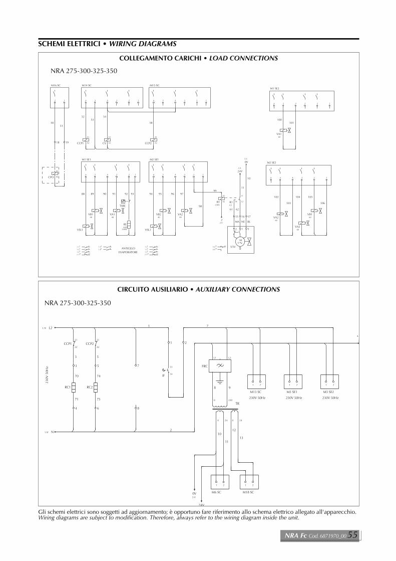
Gli schemi elettrici sono soggetti ad aggiornamento; è opportuno fare riferimento allo schema elettrico allegato all'apparecchio.Wiring diagrams are subject to modification. Therefore, always refer to the wiring diagram inside the unit.
SCHEMI ELETTRICI • WIRING DIAGRAMS��
�%����
=
0�
�
�
�
�
�
�
�
�
�
�%
��%
��
�
��
�
�
��
��
�
&���'�
���%����=
�
�
�
&��'��
���%����=
� �
&��'��
���%����=
� �
�
�6�7
�6�7
�
�
�
�
� �
�6�
&��'� &��'�
�6�
��3�
���
��3�
���
$�
���
2�
��
��
��
��
��
��
0� 0�
�
� ��
���
� ��
CIRCUITO AUSILIARIO • AUXILIARY CONNECTIONS
&���'�
�
��
�
�
��
��
&���'�
&��'��
�
��
�6�� �
�6�� �
�6�� �
�6��� ��
�
�
��
�
�
��
�
��
�6�� �
�6��
�
��
�
�
��
��
�
�
��
��2$��0,�%�3,��2,��
�
��
�
&���'�
&��'��
�
�
�6�� �
�6�� �
�6�� �
�6��� ��
�
��
�
�
��
��
�
�
��
�
�
�
��
�
�
�
�
�
��
�6��� ��
�6���
���%
�
��
��
&�
�
&�
��%
��
��
��
��
�
�6�
�%
��
�
�0
�
&��'��
&��'��
�
�
�
���
��
�
���
��
�
���
�
���
�
���
��
�
�
���
��
�
�
���
�
�3,
��3�
%'0�
%��
�%
%��
2'��
��
��3�
%'0�
%�� %��
�� ���6�
%�%
�6�
%��
%��
%��
%��
��
��
��
��
��
��
&�:���(
��
��
��
��
�6�
��
��
��
COLLEGAMENTO CARICHI • LOAD CONNECTIONS
NRA 275-300-325-350
NRA 275-300-325-350
NRA Fc Cod. 6871970_00 55

Gli schemi elettrici sono soggetti ad aggiornamento; è opportuno fare riferimento allo schema elettrico allegato all'apparecchio.Wiring diagrams are subject to modification. Therefore, always refer to the wiring diagram inside the unit.
&�'�
�
��
�
��
�
��
��
�
�
��
3
�
�
&��'�
&���'�
�
�
�
��
��
��
�
�
��
�
��
��
�
�
�
�
� �
��
�
��
&���'�
�
��
3
�
��
&���'�
�
��
��
��
�
� �
�
�
��
�
�
�
�
�
&��'�
�
�
�
� � �
3�
�
�
&�'�
�� �����&�:����
�
�
�
�
�
�
�
�
�
�
�
�
$��
�0�
�&
�0
�3�
&2%�6�
&2�3��6�
2��
2�3�
��'�6�
�3�
&2�3��6�
2��
'�2
2�3�
�0�
��
��
��
��
�
��
��
COLLEGAMENTO SICUREZZE - COMANDO A DISTANZA • SAFETY CONNECTIONS - REMOTE CONTROL
NRA 275-300-325-350
56 Aermec S.p.A.

Gli schemi elettrici sono soggetti ad aggiornamento; è opportuno fare riferimento allo schema elettrico allegato all'apparecchio.Wiring diagrams are subject to modification. Therefore, always refer to the wiring diagram inside the unit.
SCHEMI ELETTRICI • WIRING DIAGRAMS
&���'�
�
��
��
�
��
��
&���'�
�
��
�6�� �
�6�� �
�6�� �
�6��� ��
�
�
��
�
�
��
�
��
�6�� �
�6� �
�6� �
�
��
�
��
�
��
��
�
��
�6�� �
�6�� �
�6�� �
�6��� ��
�
��
��2$��0,�%�3,��2,��
�
�
��
&���'�
�
�
�6�� �
�6�� �
�6�� �
�6��� ��
�
��
�
��
�
��
��
�
�
��
�
�
�
��
�
��
�
�
�
��
�
�6��� ��
�6���
���%
�
��
��
&�
�
&�
��%
��
��
��
��
�
�6�
�%
��
��
�0
�
&��'��
&��'��
�
�
�
���
��
�
���
��
�
���
�
���
�
���
��
�
�
���
��
�
�
���
�
�3,
��3�
%'0�
%��
�%
%��
��3��
2'��
��
��3�
%'0�
%�� %��
��3��
�� ���6�
%�%
�6�
%��
%��
%��
%��
��
��
��
��
&��'��
��
��
��
��
&�:���(
��
��
&��'��
��
��
��
��
�6�
��
��
��
COLLEGAMENTO CARICHI • LOAD CONNECTIONS
NRA 500-550
&�
&�
&�
1
&�
% (
��3
&�
7�6�
��
0�<
0�<
0�<
�
3�
0$�������%����=�3>�9��
'�;6��
�,&3��'',���� �,&3��'',����� �,&3��'',���� %��2$0�2,��
0�
0�
0�
0�<
0�<
0�<
�
%��2$0�2,��
�
�%
��%
�
��3
�
�6��
�
�6�0�
$0
$�
&2�3��6�
��3��6�
�3�
&2�3���6�
��3���6�
�3��
&2�3��6�
��3��6�
�3�
&2%�6�
�%�6�
&%� &%�
&2�
�
�
�
�
�
�
0�
0�
0�
�
�
�
�
�
�
�
�
�
1 %
3�
(
�
�
�
�
�
�
�
�
�
�
�
�
1 %
3�
(
�
�
�
�
�
�
�
�
�
�
�
�
1 %
3�
(
�
�
�
�
�
�
�
�
�
�
�
�
1 %
3�
(
�
�
�
�
1 %
3�
(
��'�6�
�
�
�
�
COLLEGAMENTO ALIMENTAZIONE • POWER CONNECTIONS
NRA 500-550
NRA Fc Cod. 6871970_00 57

Gli schemi elettrici sono soggetti ad aggiornamento; è opportuno fare riferimento allo schema elettrico allegato all'apparecchio.Wiring diagrams are subject to modification. Therefore, always refer to the wiring diagram inside the unit.
SCHEMI ELETTRICI • WIRING DIAGRAMS
�6�7
�6�7
�
�
�
�
�
��
� �
�6�
�6�
&��'� &��'�
�6�
0�
�
�
�
�
�
�
�
�
�
�
�
�
�%
��%
��
�
��
�
�
��
��
�
&���'�
���%����=
�
�
�
&��'��
���%����=
� �
&��'��
���%����=
� �
���3��6�
���
��3���6�
����
��3��6�
���
���
2�
��
��
��
��
��
��
0� 0�
�
� ��
���
� ��
CIRCUITO AUSILIARIO • AUXILIARY CONNECTIONS
NRA 500-550
&�'�
�
��
��
��
�
��
��
�
�
��
3
�
�
&��'�
&���'�
�
�
��
��
�
��
��
��
�
�
��
��
�
��
��
�
�
�
��
�
��
�
�
�
�
��
�
�
��
�
��
3
�
��
�
��
�
�
��
��
�
�
�
�
�
�
�
� �
�
&��'�
�
�
�
�
�
� �
3�
�
�
&�'�
�� �����&�:����
�
�
�
�
�
�
�
�
�
�
�
�
$��
�0�
�&
�0
�3�&2%�6�
2%�
&2�3��6�
2��
2%�
2�3�
&2�3���6�
2���
2�3��
��'�6
�3�'�2
&2�3��6�
2��
2�3�
�0�
��
��
��
��
��
��
�
&���'�
&���'�
��
��
COLLEGAMENTO SICUREZZE - COMANDO A DISTANZA • SAFETY CONNECTIONS - REMOTE CONTROL
NRA 500-550
58 Aermec S.p.A.

Gli schemi elettrici sono soggetti ad aggiornamento; è opportuno fare riferimento allo schema elettrico allegato all'apparecchio.Wiring diagrams are subject to modification. Therefore, always refer to the wiring diagram inside the unit.
SCHEMI ELETTRICI • WIRING DIAGRAMS
&���'�
�
��
��
�
��
�
&���'�
�
��
�6�� �
�6�� �
�6�� �
�6��� ��
�
�
��
�
�
��
�
��
�6�� �
�6� �
�6� �
�
��
�
��
�
��
��
�
��
�6�� �
�6�� �
�6�� �
�6��� ��
�
��
��2$��0,�%�3,��2,��
�
�
��
&���'�
�
�
�6�� �
�6�� �
�6�� �
�6��� ��
�
��
�
��
�
��
��
�
�
��
�
�
�
��
�
��
�6�� �
�6�� �
�6�� �
�6��� ��
�
�
�
��
�
�6��� ��
�6���
���%
�
��
��
&�
�
&�
��%
��
��
��
��
�
�6�
�%
��
��
�0
�
&��'��
&��'��
�
�
�
���
��
�
���
��
�
���
�
���
�
���
��
�
�
���
��
�
�
���
�
�3,
��3�
%'0�
%��
�%
%��
��3��
2'��
��
��3�
%'0�
%�� %��
��3��
�� ���6�
%�%
�6�
%��
%��
%��
%��
��
��
��
��
&��'��
��
��
��
��
&�:���(
��
��
&��'��
��
��
��
��
�6�
��
��
��
COLLEGAMENTO CARICHI • LOAD CONNECTIONS
NRA 600-700
&�
&�
&�
&�
1
&�
% (
��3
&�
7�6�
&�
��
0�<
0�<
0�<
�
3�
0$�������%����=�3>�9��
'�;6��
�,&3��'',���� �,&3��'',����� �,&3��'',���� �,&3��'',����� %��2$0�2,��
0�
0�
0�
0�<
0�<
0�<
��'�6�
%��2$0�2,��
� �
�%
��%
�
��3
%��2$0�2,��
�
�6��
�
�6�0�
$0
$�
&2�3��6�
��3��6�
�3�
&2�3���6�
��3���6�
�3��
&2�3��6�
��3��6�
�3�
&2�3���6�
��3���6�
�3��
&2%�6�
�%�6�
&%� &%� &%�
&2�
�
�
�
�
�
�
0�
0�
0�
�
�
�
�
�
�
�
�
�
1 %
3�
(
�
�
�
�
�
�
�
�
�
�
�
�
1 %
3�
(
�
�
�
�
�
�
�
�
�
�
�
�
1 %
3�
(
�
�
�
�
�
�
�
�
�
�
�
�
1 %
3�
(
�
�
�
�
�
�
�
�
�
�
�
�
1 %
3�
(
�
�
�
�
1 %
3�
( 1 %
3�
(
�
�
�
�
COLLEGAMENTO ALIMENTAZIONE • POWER CONNECTIONS
NRA 600-700
NRA Fc Cod. 6871970_00 59

Gli schemi elettrici sono soggetti ad aggiornamento; è opportuno fare riferimento allo schema elettrico allegato all'apparecchio.Wiring diagrams are subject to modification. Therefore, always refer to the wiring diagram inside the unit.
SCHEMI ELETTRICI • WIRING DIAGRAMS
�7
�6�7
�
�
�
�
�
��
��
��
� �
�6�
�6�
&��'� &��'�
�6�
0�
�
�
�
�
�
�
�
�
�
�
�
�
�
�
�%
��%
��
�
��
�
�
��
��
�
&���'�
���%����=
�
�
�
&��'��
���%����=
� �
&��'��
���%����=
� �
���3��6�
���
��3���6�
����
��3��6�
���
��3���6�
����
���
2�
��
��
��
��
��
��
��
��
0� 0�
�
� ��
���
� ��
CIRCUITO AUSILIARIO • AUXILIARY CONNECTIONS
NRA 600-700
�
��
��
��
�
��
��
�
�
��
3
�
�
&��'�
&���'�
�
�
��
�
�
��
��
��
�
�
��
��
�
��
��
�
�
�
��
�
�
�
�
�
�
�
�
�
��
�
��
3
�
��
�
��
�
�
��
��
��
�
�
�
�
��
�
� �
�
�
��
��
�
�
��
��
�
�
�
�
� �
3�
�
�
&�'�
�� �����&�:����
�
�
�
�
�
�
�
�
�
�
�
�
$��
�0�
�&
&�'�
�0
�3�&2%�6�
2%�
2%�
&2�3��6�
2��
2%�
2�3�
&2�3���6�
2���
2�3��
��'�6
�3�'�2
&2�3��6�
2��
2�3�
&2�3���6�
2���
&��'�
2�3��
�0�
��
��
��
��
��
��
�
&���'�
&���'�
��
��
��
��
COLLEGAMENTO SICUREZZE - COMANDO A DISTANZA • SAFETY CONNECTIONS - REMOTE CONTROL
NRA 600-700
60 Aermec S.p.A.

Gli schemi elettrici sono soggetti ad aggiornamento; è opportuno fare riferimento allo schema elettrico allegato all'apparecchio.Wiring diagrams are subject to modification. Therefore, always refer to the wiring diagram inside the unit.
��&3,�
��%��
���
�
�
���
��&3,�
��%��
���
��%��
��%��
���
�����
��� &�
&�
&�
��3
��
'��
��2&3�
��2&3�
��2&3�
���,&
�����
����%
�����
����%
�
�
�
�
���%
����%
���%
����%
���7�
��,�7,��
��%�
����
���0
�
���3�
�
��2%
�
���3�
�
��2��
�
��2���
�
��&2
�
���3�
�
���8'�2
�
���3�
�
��2��
�
��2���
�
���0����
�
&����
&���$'30�
&�
&�
&�
&�
&
&
&�
&��
&��
&��
'(�
'(�
'(�
&��'��
&��'��
&��
&��
&��
&��
&��
&��
&��
&��
&�
&�
&��
&��
�
'����
�
'�%���
�
'�%���
�
'1����
�
'1����
�
'$���
�
'����
�
'0���
�
'0���
�
'����
�
'1(��
�
'$(��
���
2�3�9��
���
2�3�9��
���
2�3�9��
���
2�3�9��
��%��
�%��
����
����
���
&3,���
���
�
���
&%���
���
�3���
���
�
���
&%���
���
�3���
�%��
���%��
3
3
0$���&�:����%���
3
'��
��
&�
&�
3
&� ���
���%��
���
%�%��
%����
���
%����
%'0���
���
�'��
%����
���
%����
%'0���
0��
�������%
�������%
2�3�
'�%�
'��
2�3�
'�%�
��
2�3�
'��
'��
2�3�
'1(
'$(
SCHEMI ELETTRICI • WIRING DIAGRAMS
SCHEDA ELETTRONICA • ELECTRONIC BOARDCARTE ELECTRONIQUE • ELEKTRONISCHE STEUERPLATINE
NRA 275 - 300 - 325 - 350 - 500 - 550 - 600 - 700 con accumulo • with storage tank
M1 INGRESSO PROTEZIONIM2 RS 485M3 VISUALIZZATOREM4 REG. VEL. VENTIL.M5 LIBERAM6 ALIMENTAZ. SIC.24VM7 COMANDO REMOTOM8 SICUREZZE COMUNIM9 INGRESSO PROTEZIONIM10 INGRESSO PROTEZIONIM11 INGRESSO PROTEZIONIM12 INGRESSO PROTEZIONIM13 LINEA 230VM14 USCITEM15 USCITEM16 COMANDO POMPAM17 ALARME GENERALEM18 ALIMENTAZIONE 24VM19 SONDE DI PRESSIONEM20 SONDE DI PRESSIONEM21 SONDE DI TEMPERATURAM22 SONDE DI TEMPERATURAM23 SONDE DI TEMPERATURAM24 SONDE DI TEMPERATURAM25 SCHEDA DI ESPANSIONEM26 SCHEDA DI ESPANSIONE
M1 SAFETY DEVICE INPUTM2 RS 485M3 DISPLAYM4 FAN SPEED CONTROLM5 FREEM6 POWER SAF.DEV. 24VM7 REMOTE CONTROLM8 COMMON SAFETY DEVICESM9 SAFETY DEVICE INPUTM10 SAFETY DEVICE INPUTM11 SAFETY DEVICE INPUTM12 SAFETY DEVICE INPUTM13 LINE 230VM14 OUTPUTSM15 OUTPUTSM16 PUMP CONTROLM17 GENERAL ALARMM18 POWER 24VM19 PRESSURE PROBESM20 PRESSURE PROBESM21 TEMPERATURE PROBESM22 TEMPERATURE PROBES M23 TEMPERATURE PROBESM24 TEMPERATURE PROBESM25 EXPANSION BOARDM26 EXPANSION BOARD
NRA Fc Cod. 6871970_00 61

Gli schemi elettrici sono soggetti ad aggiornamento; è opportuno fare riferimento allo schema elettrico allegato all'apparecchio.Wiring diagrams are subject to modification. Therefore, always refer to the wiring diagram inside the unit.
SCHEMI ELETTRICI • WIRING DIAGRAMS
�
��
�
��
&���'�
&��'��
�
��
�
�
��
�
�
�
��
�
��
�
�
��
�
�
��
�
��
�
&���'�
&��'��
�
�
�
��
�
�
��
�
�
��
�
�
�
�
�
�
�
�
��
��
���%
�
��
��
&�
�
&�
��%
��
��
��
��
�
�%
��
�
�0
�
�
�
�
���
�
���
��
�
���
�
���
�
���
�
��
�
���
�
�
���
�
&���'�
�3, ��3�
%'0�
%��
�%
%��
2'��
��
��3�
%'0�
%�� %��
�� ��
%�%
�3,�
%��
%��
%��
%��
��
��
��
��
��
��
&�:���(
��
��
��
��
�6�
��
��
��
��
��
&��'��
&��'��
COLLEGAMENTO CARICHI • LOAD CONNECTIONS
&�
&�
&�
&�
��3
7�6�
��
�6�
0�<
0�<
0�<
�
3�
0$�������%����=�3>�9��
'�;6��
�,&3��'',���,&3��'',�
�,&3��'',���,&3��'',�
3,&3�31&3
3,&3�31&3
�
�
&�
0
0,��
%9
9
�
&�
%��2$0�2,�����
��'�6�
� �
&�
��3
�
&�
&�
�$��1$2,�1'$0$��$,���%����=
�
&�
0�
$0
$�
&2�3��6�
��3��6�
�3�
&2�3��6�
��3��6�
�3�
&23,��6�
�3,�
&3,�
&23,��6�
�3,��6
&3,�
&2%�6�
�%�6�
&% &% &% &% &%
&2�
&%
�
�
�
�
�
�
0�
0�
0�
�
�
�
�
�
�
�
�
�
1 %
3�
(
�
�
�
�
�
�
�
�
�
�
�
�
1 %
3�
(
�
�
�
�
�
�
�
�
�
�
�
�
1 %
3�
(
�
�
�
�
�
�
�
�
�
�
�
�
1 %
3�
(
�
�
�
�
�
�
�
�
�
�
�
�
�
�
�
�6�
COLLEGAMENTO ALIMENTAZIONE • POWER CONNECTIONS
NRA 275 - 300 con accumulo • with storage tank
NRA 275 - 300 - 325 - 350 con accumulo • with storage tank
62 Aermec S.p.A.

Gli schemi elettrici sono soggetti ad aggiornamento; è opportuno fare riferimento allo schema elettrico allegato all'apparecchio.Wiring diagrams are subject to modification. Therefore, always refer to the wiring diagram inside the unit.
SCHEMI ELETTRICI • WIRING DIAGRAMS��
�%����
=
0�
�
�
�
�
�
�
�
�
�
�%
��%
��
�
��
�
�
��
��
�
&���'�
���%����=
�
�
�
&��'��
���%����=
� �
&��'��
���%����=
� �
�
�
�
�
�
� �
&��'� &��'�
��3�
���
��3�
���
$�
���
2�
��
��
��
��
��
��
0� 0�
�
� ��
���
� ��
CIRCUITO AUSILIARIO • AUXILIARY CONNECTIONS
�
��
�
��
�
��
��
�
�
��
3
�
�
&��'�
&���'�
�
�
�
��
��
��
�
�
��
�
��
��
�
�
�
�
� �
��
�
��
&���'�
�
��
3
�
��
&���'�
�
��
��
��
�
� �
�
�
��
�
�
�
�
�
&��'�
�
�
��
�
��
�
��
�
�6���%
�
��
�6��%
3�
�
�
&�'�
�� �����&�:����
�
�
�
�
�
�
�
�
�
�
�
�
$��
�0�
�&
&�'�
�0
�3�
&2%�6�
&2�3��6�
2��
2�3�
��'�6
�3�
&2�3��6�
2��
'�2
2�3�
�0�
&23,��6�
&23,��6�
��
��
��
��
�
��
��
��
��
��
��
COLLEGAMENTO SICUREZZE - COMANDO A DISTANZA • SAFETY CONNECTIONS - REMOTE CONTROL
NRA 275 - 300 - 325 - 350 con accumulo • with storage tank
NRA 275 - 300 - 325 - 350 con accumulo • with storage tank
NRA Fc Cod. 6871970_00 63

Gli schemi elettrici sono soggetti ad aggiornamento; è opportuno fare riferimento allo schema elettrico allegato all'apparecchio.Wiring diagrams are subject to modification. Therefore, always refer to the wiring diagram inside the unit.
SCHEMI ELETTRICI • WIRING DIAGRAMS
&�
&�
&�
&�
7�6�
7�6�
7�6�
7�6�
0�<
0�<
0�<
�
3�
0$�������%����=�3>�9��
'�;6��
2
'
�
�
$0
$�
&2�3��6�
��3��6�
�3�
&2�3��6�
��3��6�
�3�
&23,��6�
�3,�
&3,�
&23,��6�
�3,��6
&3,�
�
�
�
�
�
�
0�
0�
0�
�
�
�
�
�
�
�
�
�
1 %
3�
(
�
�
�
�
�
�
�
�
�
�
�
�
1 %
3�
(
�
�
�
�
�
�
�
�
�
�
�
�
1 %
3�
(
�
�
�
�
�
�
�
�
�
�
�
�
1 %
3�
(
�
�
�
�
COLLEGAMENTO CARICHI • LOAD CONNECTIONS
2
'
�
�
�
�
&�
0
0,��
%9
9
�
&�
&�
��3
� �
&�
�
��3�
�
�
&�
0
0,��
%9
9
�
&�
&�
��3<
&�
�$��1$2,�1'$0$��$,���%����=
��
��6�0�
�67
�67
�67
�67
��3�
7�6�
��'�6�
7�6�
&2%�6�
�%�6�
&%� &%� &%� &%� &%� &%� &%� &%�
&2�
�
�
�
�
�
�
�
�
�
�
�
�6�
COLLEGAMENTO ALIMENTAZIONE • POWER CONNECTIONS
NRA 325 - 350 con accumulo • with storage tank
NRA 325 - 350 con accumulo • with storage tank
64 Aermec S.p.A.

Gli schemi elettrici sono soggetti ad aggiornamento; è opportuno fare riferimento allo schema elettrico allegato all'apparecchio.Wiring diagrams are subject to modification. Therefore, always refer to the wiring diagram inside the unit.
SCHEMI ELETTRICI • WIRING DIAGRAMS
0�<
0�<
0�<
�
3�
0$�������%����=�3>�9��
'�;6��
�,&3��'',���� �,&3��'',����� �,&3��'',���� 3,&3��� 3,&3���
0�
0�
0�
�
&�
&�
&�
&�
&�
7�6�
7�6�
7�6�
7�6�
$0
$�
&2�3��6�
��3��6�
�3�
&2�3���6�
��3���6�
�3��
&2�3��6�
��3��6�
�3�
&23,��6�
�3,��6�
&3,�
&23,��6�
�3,��6
&3,�
�
�
�
�
�
�
0�
0�
0�
�
�
�
�
�
�
�
�
�
1 %
3�
(
�
�
�
�
�
�
�
�
�
�
�
�
1 %
3�
(
�
�
�
�
�
�
�
�
�
�
�
�
1 %
3�
(
�
�
�
�
�
�
�
�
�
�
�
�
1 %
3�
(
�
�
�
�
�
�
�
�
�
�
�
�
1 %
3�
(
�
�
�
�
COLLEGAMENTO ALIMENTAZIONE • POWER CONNECTIONS
NRA 500 - 550 con accumulo • with storage tank
�67
�67
�67
�67
1
&�
% (
��3
&�
��'�6�
7�6�
0�
0�
0�
�
%��2$0�2,��
0�
0�
0�
0�<
0�<
0�<
%��2$0�2,��
�%
��% ��3
� � ���
�
�6��
�
�6�0�
&2%�6�
�%�6�
&%� &%�
&2�
�
�
�
�
�
�
�
�
1 %
3�
(
�
�
�
�
1 %
3�
(
�
�
�
�
COLLEGAMENTO ALIMENTAZIONE • POWER CONNECTIONS
NRA 500 - 550 con accumulo • with storage tank
NRA Fc Cod. 6871970_00 65

Gli schemi elettrici sono soggetti ad aggiornamento; è opportuno fare riferimento allo schema elettrico allegato all'apparecchio.Wiring diagrams are subject to modification. Therefore, always refer to the wiring diagram inside the unit.
0�
�
�
�
�
�
�
�
�
�
�
�
�
�%
��%
��
�
��
�
�
��
��
�
&���'�
���%����=
�
�
�
&��'��
���%����=
� �
&��'��
���%����=
� �
�
�
�
�
�
�
��
� �
&��'� &��'�
��3�
���
��3��
����
��3�
���
���
2�
��
��
��
��
��
��
0� 0�
�
� ��
���
� ��
CIRCUITO AUSILIARIO • AUXILIARY CONNECTIONS
NRA 500 - 550 con accumulo • with storage tank
�
��
�
��
&���'�
�
��
�
�
��
�
�
�
��
�
��
�
�
��
�
��
�
��
��2$��0,�%�3,��2,��
���1&10,
�
�
��
&���'�
�
�
�
��
�
��
�
��
�
�
��
�
�
�
�
�
�
�
��
����%
�
��
��
&�
�
&�
��%
��
��
��
��
�
�%
��
��
�0
�
��
�
�
��
�
���
�
���
�
���
�
���
�
���
�
�
���
�
�
���
�
&���'�
�3,� ��3�
%'0�
%��
�%
%��
��3��
2'��
��
��3�
%'0�
%�� %��
�� ��
%�%
�3,�
%��
%��
%��
%��
��
��
��
��
&��'��
��
��
��
��
&�:���(
��
��
&��'��
��
�� ��
��
��
��
��
&��'��
&��'��
��
��
��
�� ������
COLLEGAMENTO CARICHI • LOAD CONNECTIONS
NRA 500 - 550 con accumulo • with storage tank
66 Aermec S.p.A.

Gli schemi elettrici sono soggetti ad aggiornamento; è opportuno fare riferimento allo schema elettrico allegato all'apparecchio.Wiring diagrams are subject to modification. Therefore, always refer to the wiring diagram inside the unit.
�
��
��
��
�
��
��
�
�
��
3
�
�
&��'�
&���'�
�
�
��
�
�
��
��
��
�
�
��
��
�
��
��
�
�
�
��
�
��
�
�
�
�
��
�
�
��
�
��
3
�
��
�
��
�
�
��
��
�
�
�
�
�
�
�
� �
�
&��'�
�
�
��
�
��
�
��
�
�
��%
�
��
�%
3�
�
�
&�'�
�� �����&�:����
�
�
�
�
�
�
�
�
�
�
�
�
$��
�0�
�&
&�'�
�0
�3�&2%
2%�
2%�
&2�3�
2��
2%�
2�3�
&2�3��
2���
2�3��
��'
�3�'�2
&2�3�
2��
2�3�
&23,�
�0�
&23,�
��
��
��
��
��
��
�
&���'�
&���'�
��
��
��
��
��
��
NRA 500 - 550 con accumulo • with storage tank
SCHEMI ELETTRICI • WIRING DIAGRAMS
NRA Fc Cod. 6871970_00 67

Gli schemi elettrici sono soggetti ad aggiornamento; è opportuno fare riferimento allo schema elettrico allegato all'apparecchio.Wiring diagrams are subject to modification. Therefore, always refer to the wiring diagram inside the unit.
SCHEMI ELETTRICI • WIRING DIAGRAMS
0�<
0�<
0�<
�
3�
0$�������%����=�3>�9��
'�;6��
�,&3��'',���� �,&3��'',����� �,&3��'',���� �,&3��'',����� 3,&3��� 3,&3���
0�
0�
0�
�
&�
&�
&�
&�
&�
&�
$0
$�
&2�3�
��3�
�3�
&2�3��
��3��
�3��
&2�3�
��3�
�3�
&2�3��
��3��
�3��
&23,�
�3,�
&3,�
&23,�
�3,�
&3,�
�
�
�
�
�
�
0�
0�
0�
�
�
�
�
�
�
�
�
�
1 %
3�
(
�
�
�
�
�
�
�
�
�
�
�
�
1 %
3�
(
�
�
�
�
�
�
�
�
�
�
�
�
1 %
3�
(
�
�
�
�
�
�
�
�
�
�
�
�
1 %
3�
(
�
�
�
�
�
�
�
�
�
�
�
�
1 %
3�
(
�
�
�
�
�
�
�
�
�
�
�
�
1 %
3�
(
�
�
�
�
COLLEGAMENTO ALIMENTAZIONE • POWER CONNECTIONS
NRA 600 - 650 - 700 con accumulo • with storage tank
�67
�67
�67
�67
1
&�
% (
��3
&�
7�6�
&�
0�
0�
0�
�
%��2$0�2,��
0�
0�
0�
0�<
0�<
0�<
%��2$0�2,��
�%
��% ��3
��'�6�
�
%��2$0�2,��
� ���
�
�6��
�
�6�0�
&2%�6�
�%�6�
&%� &%� &%�
&2�
�
�
�
�
�
�
�
�
1 %
3�
(
�
�
�
�
1 %
3�
( 1 %
3�
(
�
�
�
�
COLLEGAMENTO ALIMENTAZIONE • POWER CONNECTIONS
NRA 600 - 650 - 700 con accumulo • with storage tank
68 Aermec S.p.A.

Gli schemi elettrici sono soggetti ad aggiornamento; è opportuno fare riferimento allo schema elettrico allegato all'apparecchio.Wiring diagrams are subject to modification. Therefore, always refer to the wiring diagram inside the unit.
�
��
�
��
&���'�
�
��
�
�
��
�
�
�
��
�
��
�
�
��
�
��
�
��
��2$��0,�%�3,��2,��
���1&10,
�
�
��
&���'�
�
�
�
��
�
��
�
��
�
�
��
�
�
�
�
��
�
�
�
��
����%
�
��
��
&�
�
&�
��%
��
��
��
��
�
�%
��
��
�0
�
��
�
�
��
�
���
�
���
�
���
�
���
�
���
�
�
���
�
�
���
�
�� �� �� ��
��
&���'�
�3,� ��3�
%'0�
%��
�%
%��
��3��
2'��
��
��3�
%'0�
%�� %��
��3��
�� ��
%�%
�3,�
%��
%��
%��
%��
��
��
��
��
&��'��
��
��
��
��
&�:���(
��
��
&��'��
��
��
��
�� ��
��
��
��
��
&��'��
&��'��
��
��
��
COLLEGAMENTO CARICHI • LOAD CONNECTIONS
NRA 600 - 650 - 700 con accumulo • with storage tank
NRA Fc Cod. 6871970_00 69

Gli schemi elettrici sono soggetti ad aggiornamento; è opportuno fare riferimento allo schema elettrico allegato all'apparecchio.Wiring diagrams are subject to modification. Therefore, always refer to the wiring diagram inside the unit.
SCHEMI ELETTRICI • WIRING DIAGRAMS
0�
�
�
�
�
�
�
�
�
�
�
�
�
�
�
�%
��%
��
�
��
�
�
��
��
�
&���'�
���%����=
�
�
�
&��'��
���%����=
� �
&��'��
���%����=
� �
�
�
�
�
�
�
��
��
��
� �
&��'� &��'�
��3�
���
��3��
����
��3�
���
��3��
����
���
2�
��
��
��
��
��
��
��
��
0� 0�
�
� ��
���
� ��
�6
�6
CIRCUITO AUSILIARIO • AUXILIARY CONNECTIONS
�
��
��
��
�
��
��
�
�
��
3
�
�
&��'�
&���'�
�
�
��
��
�
��
��
��
�
�
��
�
�
��
��
�
�
�
��
�
�
�
�
�
�
�
�
�
��
�
��
3
�
��
�
��
�
�
��
��
��
�
�
�
�
��
�
� �
�
�
��
��
�
�
��
��
�
��
�
��
�
��
�
�
��%
�
��
�%
3�
�
�
&�'�
�� �����&�:����
�
�
�
�
�
�
�
�
�
�
�
�
$��
�0�
�&
&�'�
�0
�3�&2%
2%�
2%�
&2�3�
2��
2%�
2�3�
&2�3��
2���
2�3��
��'�6�
�3�'�2
&2�3�
2��
2�3�
&2�3��
2���
&��'�
2�3��
&23,�
�0�
&23,�
��
��
��
��
��
��
�
&���'�
&���'�
��
��
��
��
��
��
��
��
COLLEGAMENTO SICUREZZE - COMANDO A DISTANZA • SAFETY CONNECTIONS - REMOTE CONTROL
NRA 600 - 650 - 700 con accumulo • with storage tank
NRA 600 - 650 - 700 con accumulo • with storage tank
70 Aermec S.p.A.

SERVIZI ASSISTENZAVALLE D’AOSTAAOSTA AERSAT TORINO snc di Borioli Secondino & C. Strada Bertolla, 163 - 10156 Torino 0115 611 220PIEMONTEALESSANDRIA - ASTI - CUNEO BELLISI s.r.l. Corso Savona, 245 - 14100 Asti 0141 556 268BIELLA - VERCELLI LOMBARDI SERVICES s.r.l. Via Piave, 25 - 13894 Gaglianico (BI) 0152 543 189NOVARA - VERBANIA (tutta la gamma esclusi split system) AIR CLIMA SERVICE di F. & C. s.a.s. Via Pertini, 9 - 21021 Angera (VA) 0331 932 110NOVARA - VERBANIA (split system) CI. Elle Clima snc di Benvegnù L. Via S. Anna, 6 - 21018 Sesto Calende (VA) 0331 914 186TORINO AERSAT TORINO snc di Borioli Secondino & C. Strada Bertolla, 163 - 10156 Torino 0115 611 220LIGURIAGENOVA - SAVONA BRINZO ANDREA Via Del Commercio, 27 1/C2 - 16167 Genova Nervi 0103 298 314IMPERIA AERFRIGO di A. Amborno e C. s.n.c . Via Z. Massa, 152/154 - 18038 Sanremo (IM) 0184 575 257LA SPEZIA TECNOFRIGO di Veracini Nandino Via Lunense, 59 - 54036 Marina di Carrara (MS) 0585 631 831LOMBARDIABERGAMO ESSEBI di Sironi Bruno e C. sas Via Pacinotti, 98 - 24100 Bergamo 035 346 869BRESCIA TERMOTEC. di Vitali G. & C. s.n.c. Via G. Galilei - Trav. I°, 2 - 25010 S. Zeno S. Naviglio (BS) 0302 160 812COMO - SONDRIO - LECCO PROGIELT di Libeccio & C. s.r.l. Via Rigamonti, 21 - 22020 San Fermo della Battaglia (CO) 031 536 423CREMONA MORETTI ALBANO & C. s.n.c. Via Manini, 2/C - 26100 Cremona 0372 433 624LODI CLIMA LODI di Sali Cristian Via Felice Cavallotti, 29 - 26900 Lodi 0371 549 304MANTOVA F.LLI COBELLI di Cobelli Davide & C. s.n.c. Via Tezze, 1 - 46040 Cavriana (MN) 0376 826 174
MILANO CRIO SERVICE s.r.l. Via G. Giannini, 4 - 20151 Milano 0233 498 280S.A.T.I.C. di Lovato Dario S.S. Padana Superiore 11, 1/E7 - 20060 Cassina dè Pecchi (MI) 0295 299 034
PAVIA BATTISTON GIAN LUIGI Via Liguria, 4/A - 27058 Voghera (PV) 038 362 253VARESE (tutta la gamma esclusi split system) AIR CLIMA SERVICE di F. & C. s.a.s. Via Pertini, 9 - 21021 Angera (VA) 0331 932 110VARESE (split system) CI. Elle Clima snc di Benvegnù L. Via S. Anna, 6 - 21018 Sesto Calende (VA) 0331 914 186TRENTINO ALTO ADIGEBOLZANO - TRENTO SESTER F. s.n.c. di Sester A. & C. Via E. Fermi, 12 - 38100 Trento 0461 920 179FRIULI VENEZIA GIULIAPORDENONE CENTRO TECNICO s.n.c. di Menegazzo G. & C. Via Conegliano, 94/A - 31058 Susegana (TV) 0438 450 271TRIESTE - GORIZIA LA CLIMATIZZAZIONE TRIESTE SRL Strada della Rosandra, 269 - 34018 San Dorligo della Valle(TS) 040 828 080UDINE S.A.R.E. di Musso Dino Corso S. Valentino, 4 - 33050 Fraforeano (UD) 0432 699 810VENETOBELLUNO FONTANA SOFFIRO FRIGORIFERI s.n.c. Via Sampoi, 68 - 32020 Limana (BL) 0437 970 042LEGNAGO DE TOGNI STEFANO Via De Nicola, 2 - 37045 Legnago (VR) 044 220 327PADOVA CLIMAIR s.a.s. di F. Cavestro & C. Via Nona Strada, 36 - Z.I. - 35129 Padova 049 772 324ROVIGO FORNASINI MAURO Via Sammartina, 18/A - 44040 Chiesuol del Fosso (FE) 0532 978 450TREVISO CENTRO TECNICO s.n.c. di Menegazzo G. & C. Via Conegliano, 94/A - 31058 Susegana (TV) 0438 450 271VENEZIA SIMIONATO GIANNI Via Trento, 29 - 30174 Mestre (VE) 041 959 888VERONA (escluso LEGNAGO) ALBERTI FRANCESCO Via Tombetta, 82 - 37135 Verona 045 509 410VICENZA (split system) ASSICLIMA di Colpo Donato Via Capitello, 63/c - 36010 Cavazzale (VI) 336-813963VICENZA BIANCHINI GIOVANNI & IVAN snc Via G. Galilei, 1Z - Loc. Nogarazza - 36057 Arcugnano (VI) 0444 569 481EMILIA ROMAGNABOLOGNA EFFEPI s.n.c. di Ferrazzano & Proto Via I° Maggio, 13/8 - 40044 Pontecchio Marconi (BO) 0516 781 146FERRARA FORNASINI MAURO Via Sammartina, 18/A - 44040 Chiesuol del Fosso (FE) 0532 978 450FORLÌ - RAVENNA - RIMINI ALPI GIUSEPPE Via N. Copernico, 100 - 47100 Forlì 0543 725 589MODENA Nord CLIMASERVICE di Golinelli Stefano Via Per Modena, 18/E - 41034 Finale Emilia (MO) 053 592 156MODENA Sud AERSAT s.n.c. di Leggio M. & Lolli S. Piazza Beccadori, 19 - 41057 Spilamberto (MO) 059 782 908PARMA ALFATERMICA s.n.c. Galbano & Biondo Via Mantova, 161 - 43100 Parma 0521 776 771PIACENZA MORETTI ALBANO & C. s.n.c. Via Manini, 2/C - 26100 Cremona 0372 433 624REGGIO EMILIA ECOCLIMA S.r.l. Via Maestri del lavoro, 14 - 42100 Reggio Emilia 0522 558 709TOSCANAAREZZO CLIMA SERVICE ETRURIA s.n.c. Via G. Caboto, 69/71/73/75 - 52100 Arezzo 0575 900 700FIRENZE - PRATO S.E.A.T. di Benedetti Giancarlo Via P. Fanfani, 55 - 50127 Firenze 0554 255 721GROSSETO ACQUA e ARIA SERVICE s.r.l. Via D. Lazzaretti, 8A - 58100 Grosseto 0564 410 579LIVORNO - PISA SEA s.n.c. di Rocchi R. & C. Via dell’Artigianato, Loc.Picchianti - 57121 Livorno 0586 426 471LUCCA - PISTOIA FRIGOTEC. s.n.c. G. & MC. BENEDETTI Via V. Civitali, 2 - 55100 Lucca 0583 491 089MASSA CARRARA TECNOFRIGO di Veracini Nandino Via Lunense, 59 - 54036 Marina di Carrara (MS) 0585 631 831SIENA FRIGOTECNICA SENESE s.n.c. di B. & C. Strada di Cerchiaia, 42 - Z.A. 53100 Siena 0577 284 330MARCHEANCONA - PESARO MARCHETTI SAURO Via M. Ricci, 16/A - 60020 Palombina (AN) 071 889 435MACERATA - ASCOLI PICENO CAST s.n.c. di Antinori-Cardinali & R. Via D. Alighieri, 68 - 62010 Morrovalle (MC) 0733 865 271UMBRIAPERUGIA A.I.T. s.r.l. Via dell’industria, Z.I. Molinaccio - 06154 Ponte S. Giovanni (PG) 0755 990 564TERNI CAPOCCETTI OTELLO Via G. Medici, 14 - 05100 Terni 0744 277 169ABRUZZOCHIETI - PESCARA - TERAMO - L’AQUILA PETRONGOLO DINO Via Torremontanara, 30 - 66010 Torre Vecchia Teatina (CH) 0871 360 311ISERNIA - CAMPOBASSSOLAZIOFROSINONE - LATINA MASTROGIACOMO AIR SERVICE - M. C. P.zza Berardi, 16 - 03023 Ceccano (FR) 0775 601 403RIETI CAPOCCETTI OTELLO Via G. Medici, 14 - 05100 Terni 0744 277 169ROMA TAGLIAFERRI 2001 s.r.l. Via Guidonia Montecelio snc - 00191 Roma 063 331 234VITERBO AIR FRIGO di Massimo Piacentini Viale Baccelli, 74 - 00053 Civitavecchia (RM) 0766 541 945CAMPANIAAVELLINO SAIT s.r.l. Via S. D’Alessandro, 20 - 84014 Nocera Inferiore (SA) 0815 178 451CAPRI CATALDO COSTANZO Via Tiberio, 7/F - 80073 Capri (NA) 0818 378 479NAPOLI - CASERTA - BENEVENTO AERCLIMA Sud s.n.c. di Fisciano Carmelo & C. Via Nuova Toscanella, 34/c - 80145 Napoli 0815 456 465SALERNO GDS TECNO Via Acquasanta, 16 Z.I. - 84131 Salerno 089 771 167PUGLIABARI KLIMAFRIGO s.r.l. Via Vallone, 81 - 70121 Bari 0805 538 044FOGGIA CLIMACENTER di Amedeo Nardella Via Carmicelli, 29 Pal. A Sc. A - 71016 San Severo (FG) 3396 522 443LECCE - BRINDISI GRASSO VINCENZO Via G. Vinci, 15 - 73052 Parabita (LE) 0833 595 267TARANTO ORLANDO PASQUALE Via Vespucci, 5 - 74023 Grottaglie (TA) 0995 639 823BASILICATAMATERA - POTENZA AERLUCANA di A. Scalcione Via Dei Peucezi, 23 - 75100 Matera 0835 381 467MOLISECAMPOBASSO - ISERNIA PETRONGOLO DINO Via Torremontanara, 30 - 66010 Torre Vecchia Teatina (CH) 0871 360 311CALABRIACATANZARO - CROTONE A.E.C. di Ranieri Annarita Via B. Miraglia, 72 - 88100 Catanzaro 0961 771 123COSENZA CLIMA SUD s.n.c. dei F.lli Mandarino Via Tevere, 84/86 - 87030 Roges di Rende (CS) 0984 465 004REGGIO CALABRIA REPACI ANTONINO Via Militare 2nda Trav. 8D - 89053 Catona (RC) 0965 301 431REGGIO CALABRIA - VIBO VALENTIA MANUTENSUD di Antonio Amato Via F. Cilea, 62 - 88065 Guardavalle (CZ) 096 786 516SICILIACATANIA - MESSINA GIUFFRIDA GIUSEPPE Via Mandrà, 15/A - 95124 Catania 095 351 485ENNA - CALTANISSETTA - AGRIGENTO FONTI FILIPPO Viale Aldo Moro, 141 - 93019 Sommatino (CL) 0922 871 333PALERMO - TRAPANI S.E.A.T. di A. Parisi & C. s.n.c. Via T. Marcellini, 7 - 90135 Palermo 091 591 707SIRACUSA - RAGUSA FINOCCHIARO ANTONINO Via Paternò, 71 - 96100 Siracusa 0931 756 911SARDEGNACAGLIARI - ORISTANO MUREDDU L. di Mureddu Pasquale Via Garigliano, 13 - 09122 Cagliari 070 284 652SASSARI - NUORO POSADINU SALVATORE IGNAZIO Z.I. Predda Niedda - Sud - Strada 11 - 07100 Sassari 079 261 234

I dati tecnici riportati nella presente documentazione non sono impe-gnativi.L’Aermec S.p.A. si riserva la facoltà di apportare in qualsiasi momentotutte le modifiche ritenute necessarie per il miglioramento del prodotto.
Technical data shown in this booklet are not binding.
Aermec S.p.A. shall have the right to introduce at any time whatevermodifications deemed necessary to the improvement of the product.
Aermec partecipa al Programma diCertificazione EUROVENT.
I prodotti interessati figurano nella GuidaEUROVENT dei Prodotti Certificati.
Aermec is partecipating in the EUROVENTCertification Programme.
Products are as listed in the EUROVENTDirectory of Certified Products.
AERMEC S.p.A.I-37040 Bevilacqua (VR) Italia – Via Roma, 44Tel. (+39) 0442 633111Telefax 0442 93730 – (+39) 0442 93566www.aermec.com - [email protected]
carta riciclatarecycled paperpapier recyclérecycled Papier
19 1
1 02
3