registration id: itsme [email protected] … id: [email protected] released under...
TRANSCRIPT

Registration ID: [email protected]
Released Under Creative Commons Attribution-ShareAlike 3.0 Unported Licence
Automatic Diesel Generator Control on Main Supply/Power Failure
Abstract:
By using “GR Sakura Board” Diesel Generator set can start and stop automatically very nicely on main
supply failure. In this case DG Set must have self start facility. This idea may be very use full for hotels,
restaurant even home uses. The block diagram is give in following pages. At the time of power failure or
supply is abnormal i.e. over voltage or under voltage condition main supply will be switched off and DG Set
start automatically. When power supply is restored or voltage become normal DG Set will be stopped and
Power supply switched on automatically.
The algorithm is given as under:
1. Check the power supply is normal or not.
2. If it is normal then switched on it.
3. If supply is become abnormal or fail switched off it and wait for 30 Sec.
4. With in 30 sec if supply become normal then wait for anther 10 sec.
5. In this 10 sec if supply is stable then switch on the main power supply incomer.
6. After the period of 30 sec supply is not restored or if supply is not stable within period of 10 sec
the DG Set starting process will be start.
7. A starting pulse of 3 sec given to DG Set. If DG Set not start then it attempt for next two times
with delay of 15 sec. If ultimately DG Set not get start then an alarm given that is “DG Set fail
to start” and wait for power supply normalisation.
8. If DG Set get start then it wait for 1 or 2 min for idle running.
9. After 1 or 2 min period it will check the Voltage of DG Set. If it is normal then switch on the DG
Incomer.
10. In this stage there may be two cases:
Case 1: If supply is restored up to the stage 8 i.e. within the DG Set starting process then the control
unit will repeat the stage 5 and stop the DG Set.
Case 2: If supply restored after stage 9 then follow the next stage.
11. When supply become normal the after delay of 10 sec switch off the DG incomer and switch on
the main supply incomer.
12. After that delay 30 sec a Stop pulse given to DG Set.
13. Here if the supply is become again abnormal before the DG stopped then it will switch off the main
supply incomer and switch on the DG incomer.
However for demonstration purpose total mater can be simulate by using a small DC Motor-Generator
Set.
Page 1 of 23
Registration ID: [email protected]
Released Under Creative Commons Attribution-ShareAlike 3.0 Unported Licence
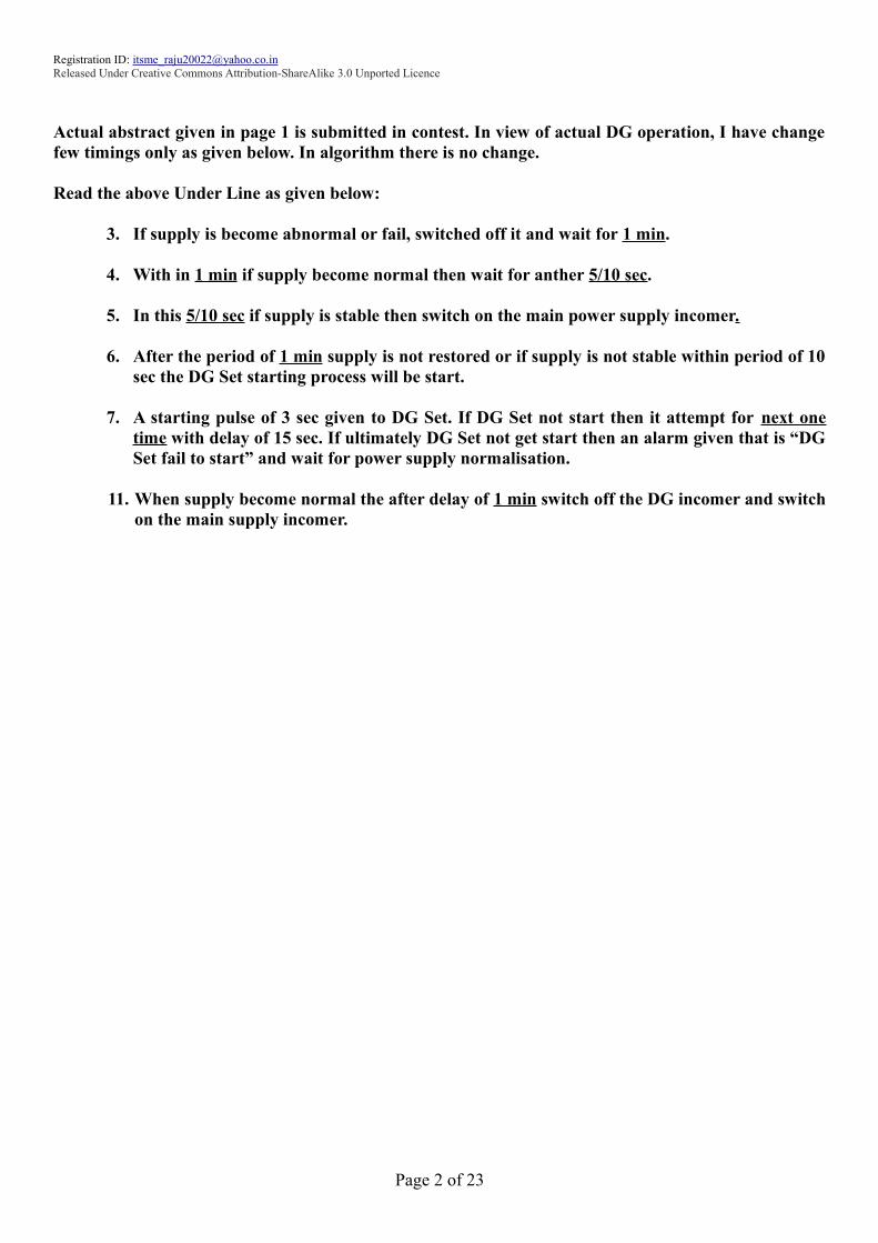
Actual abstract given in page 1 is submitted in contest. In view of actual DG operation, I have change
few timings only as given below. In algorithm there is no change.
Read the above Under Line as given below:
3. If supply is become abnormal or fail, switched off it and wait for 1 min.
4. With in 1 min if supply become normal then wait for anther 5/10 sec.
5. In this 5/10 sec if supply is stable then switch on the main power supply incomer.
6. After the period of 1 min supply is not restored or if supply is not stable within period of 10
sec the DG Set starting process will be start.
7. A starting pulse of 3 sec given to DG Set. If DG Set not start then it attempt for next one
time with delay of 15 sec. If ultimately DG Set not get start then an alarm given that is “DG
Set fail to start” and wait for power supply normalisation.
11. When supply become normal the after delay of 1 min switch off the DG incomer and switch
on the main supply incomer.
Page 2 of 23

Registration ID: [email protected]
Released Under Creative Commons Attribution-ShareAlike 3.0 Unported Licence
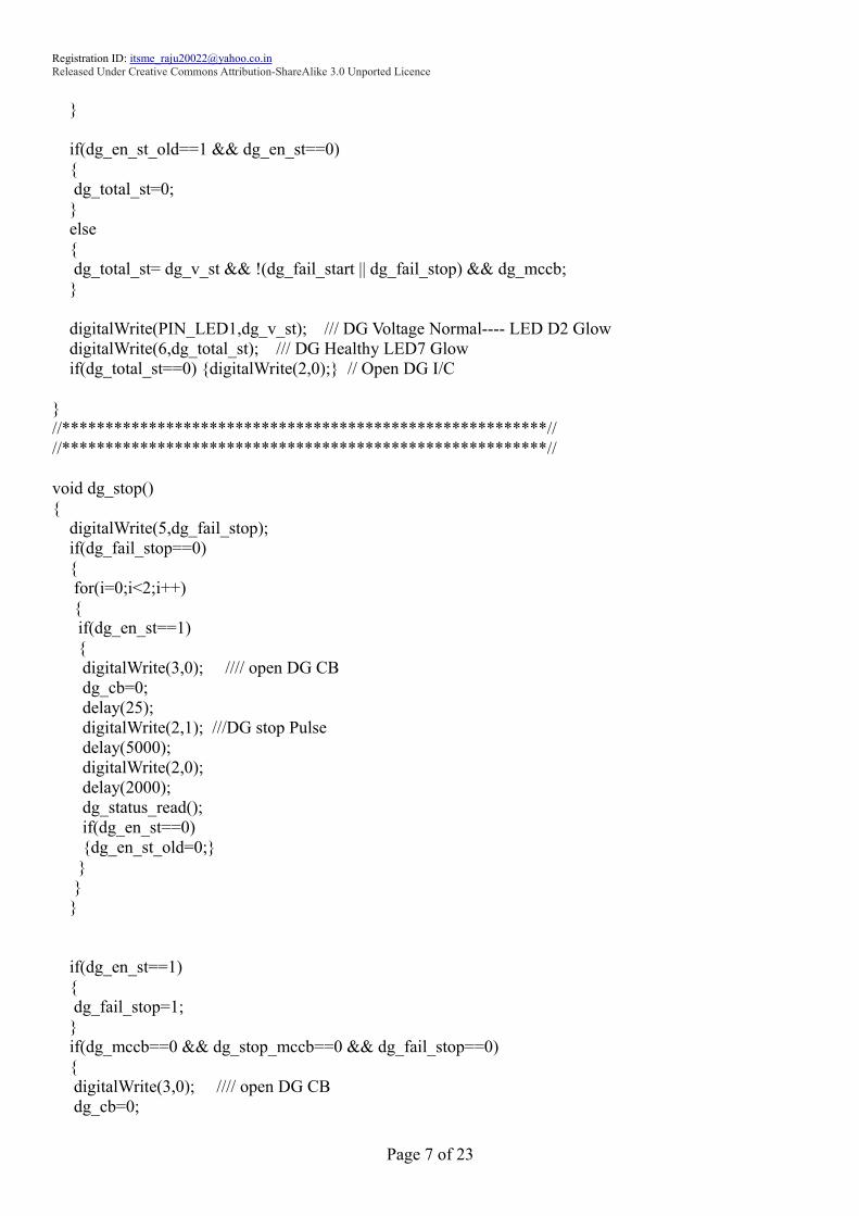
Source Code of Automatic Diesel Generator Control on Main Supply/Power Failure
/*GR-SAKURA Sketch Template Version: V1.07*/
/*DG Automation*/
/*Rgistration ID: [email protected]*/
#include <rxduino.h>
long int micv,dgv;
int uv1=0,ov1=0,mainst=0,old1=0,new1=0;
int i; ///use for loop
int j=0; //// Use for first delay on Startup
int uv2=0,ov2=0,dg_mccb=0,dg_v_st=0,dg_en_st=0,dg_total_st=0,dg_cb=0,dg_en_st_old=0;
int dg_stop_mccb=0,dg_fail_stop=0,dg_fail_start=0,dg_fail_start1=0;
void mainicstatus();
void mainiccb_cl();
void dg_status_read();
void dg_stop();
void dg_start();
void dg_iccb_cl();
void reset();
void setup()
{
pinMode(PIN_LED0,OUTPUT); //Main I/c healthy
pinMode(PIN_LED1,OUTPUT); //DG Voltage Normal
pinMode(PIN_LED2,OUTPUT); //DG DG MCCB on
pinMode(PIN_LED3,OUTPUT); // Spare
pinMode(0,OUTPUT); // Main I/C Contactor Close
pinMode(1,OUTPUT); // DG start pulse
pinMode(2,OUTPUT); // DG stop pulse
pinMode(3,OUTPUT); // DG I/C Contactor close
pinMode(4,OUTPUT); // DG fail to start
pinMode(5,OUTPUT); // DG fail to stop
pinMode(6,OUTPUT); // DG Healthy
pinMode(7,INPUT_PULLUP); // DG MCCB status input
analogReference(RAW12BIT); // Main I/C voltage read
attachInterrupt(3,reset,RISING); // Reset Alarm
}
Page 3 of 23

Registration ID: [email protected]
Released Under Creative Commons Attribution-ShareAlike 3.0 Unported Licence
void loop()
{
if(j==0)
{
delay(5000);
dg_status_read();
j=1;
}
mainicstatus();
if(old1!=new1)
{
if(mainst==0)
{
for(i=0;i<1;i++) {delay(60000);}
}
else {delay(60000);}
old1=new1;
mainicstatus();
}
if(mainst==1)
{
mainiccb_cl();
if(dg_en_st==1) {delay(30000);}
mainicstatus();
if(mainst==1)
{
dg_status_read();
dg_stop();
}
}
else
{
dg_status_read();
dg_start();
dg_status_read();
if(dg_fail_start==1 && dg_fail_start1==1)
{
digitalWrite(3,0); //// open DG CB
dg_cb=0;
delay(25);
digitalWrite(2,1); ///DG stop Pulse
delay(5000);
digitalWrite(2,0);
dg_fail_start1=0;
}
dg_iccb_cl();
}
Page 4 of 23

Registration ID: [email protected]
Released Under Creative Commons Attribution-ShareAlike 3.0 Unported Licence
}
//****************************************************//
//****************************************************//
void mainicstatus()
{
micv=analogRead(0);
//****** Main I/C Over Voltage**********//
if (micv>2792) //v=2.25v
{
ov1=1;
delay(1000);
micv=analogRead(0);
}
if (micv<2731) ///v=2.2v
{
ov1=0;
}
//****************************************//
//****** Main I/C Under Voltage**********//
if (micv<2110) ///v=1.7v
{
uv1=1;
delay(5000);
micv=analogRead(0);
}
if (micv>2234) // v=1.8v
{
uv1=0;
}
//***************************************//
mainst=!(uv1 || ov1);
if(mainst==0) {digitalWrite(0,0);} /// Open Main I/C CB if voltage unhealthy
new1=mainst;
digitalWrite(PIN_LED0,mainst); /// Main Healthy LED D1 Glow
}
//*********************************************************//
void mainiccb_cl()
{
digitalWrite(3,0); //// open DG CB
dg_cb=0;
delay(25);
digitalWrite(0,mainst); /// Close Main I/C CB
}
//*******************************************************//
void dg_status_read()
{
Page 5 of 23

Registration ID: [email protected]
Released Under Creative Commons Attribution-ShareAlike 3.0 Unported Licence
dg_mccb=!digitalRead(7);
digitalWrite(PIN_LED2,dg_mccb); ///DG MCCB Close----LED D3 Glow
dgv=analogRead(1);
if(dg_mccb==1)
{
dg_stop_mccb=0;
//****** DG Over Voltage**********//
if (dgv>2792) //v=2.25v
{
ov2=1;
delay(1000);
dgv=analogRead(1);
}
if (dgv<2731) ///v=2.2v
{
ov2=0;
}
//****************************************//
//****** DG Under Voltage**********//
if (dgv<2110) ///v=1.7v
{
uv2=1;
delay(5000);
dgv=analogRead(1);
}
if (dgv>2234) // v=1.8v
{
uv2=0;
}
//***************************************//
}
dg_v_st=!(uv2 || ov2) && dg_mccb;
if(dg_v_st==0)
{
digitalWrite(3,0); //// Open DG I/C CB if DG unhealthy
dg_cb=0;
}
if(dg_mccb==1 && dgv>1200)
{
dg_en_st=1;
dg_en_st_old=1;
}
else
{
dg_en_st=0;
Page 6 of 23
Registration ID: [email protected]
Released Under Creative Commons Attribution-ShareAlike 3.0 Unported Licence
}
if(dg_en_st_old==1 && dg_en_st==0)
{
dg_total_st=0;
}
else
{
dg_total_st= dg_v_st && !(dg_fail_start || dg_fail_stop) && dg_mccb;
}
digitalWrite(PIN_LED1,dg_v_st); /// DG Voltage Normal---- LED D2 Glow
digitalWrite(6,dg_total_st); /// DG Healthy LED7 Glow
if(dg_total_st==0) {digitalWrite(2,0);} // Open DG I/C
}
//********************************************************//
//********************************************************//
void dg_stop()
{
digitalWrite(5,dg_fail_stop);
if(dg_fail_stop==0)
{
for(i=0;i<2;i++)
{
if(dg_en_st==1)
{
digitalWrite(3,0); //// open DG CB
dg_cb=0;
delay(25);
digitalWrite(2,1); ///DG stop Pulse
delay(5000);
digitalWrite(2,0);
delay(2000);
dg_status_read();
if(dg_en_st==0)
{dg_en_st_old=0;}
}
}
}
if(dg_en_st==1)
{
dg_fail_stop=1;
}
if(dg_mccb==0 && dg_stop_mccb==0 && dg_fail_stop==0)
{
digitalWrite(3,0); //// open DG CB
dg_cb=0;
Page 7 of 23

Registration ID: [email protected]
Released Under Creative Commons Attribution-ShareAlike 3.0 Unported Licence
delay(30000);
dg_status_read();
if(dg_mccb==0 && dg_en_st_old==1)
{
digitalWrite(2,1); ///DG stop Pulse
delay(5000);
digitalWrite(2,0);
dg_stop_mccb=1;
dg_en_st_old=0;
}
}
if(dg_en_st_old==1 && dg_en_st==0 && dg_total_st==0)
{
digitalWrite(2,1); ///DG stop Pulse
delay(5000);
digitalWrite(2,0);
dg_stop_mccb=1;
dg_en_st_old=0;
}
digitalWrite(5,dg_fail_stop);
}
//*****************************************************************///
void dg_start()
{
digitalWrite(4,dg_fail_start);
digitalWrite(0,mainst);
if(dg_en_st==0 && dg_en_st_old==0 && dg_fail_start==0 && dg_fail_stop==0)
{
for(i=0;i<2;i++)
{
if(dg_en_st==0 && dg_mccb==1)
{
digitalWrite(1,1);
delay(3000);
digitalWrite(1,0);
delay(10000);
dg_status_read();
}
}
if(dg_en_st==0) {dg_fail_start1=1;}
}
if(dg_en_st==0) {dg_fail_start=1;}
if(dg_v_st==0 && dg_en_st==1) {dg_fail_start=1;}
if(dg_en_st==1 && dg_cb==0) {delay(30000);} // Delay 30sec when DG on and DG CB open
digitalWrite(4,dg_fail_start);
}
//*********************************************************//
void dg_iccb_cl()
Page 8 of 23

Registration ID: [email protected]
Released Under Creative Commons Attribution-ShareAlike 3.0 Unported Licence
{
if(dg_total_st==1)
{
digitalWrite(0,0); /// Main IC CB Open
delay(25);
digitalWrite(3,dg_total_st); /// DG IC CB Close
dg_cb=dg_total_st;
}
else
{
digitalWrite(3,dg_total_st);
dg_cb=dg_total_st;
dg_stop();
}
}
///*******************************************************////
void reset()
{
dg_fail_stop=0;
dg_fail_start=0;
dg_stop_mccb=0;
dg_en_st_old=0;
j=0;
digitalWrite(4,dg_fail_start);
digitalWrite(5,dg_fail_stop);
}
/*****************************END*******************////
Page 9 of 23
Registration ID: [email protected]
Released Under Creative Commons Attribution-ShareAlike 3.0 Unported Licence
Automatic Diesel Generator Control on Main Supply/Power Failure
Description & Its Operation
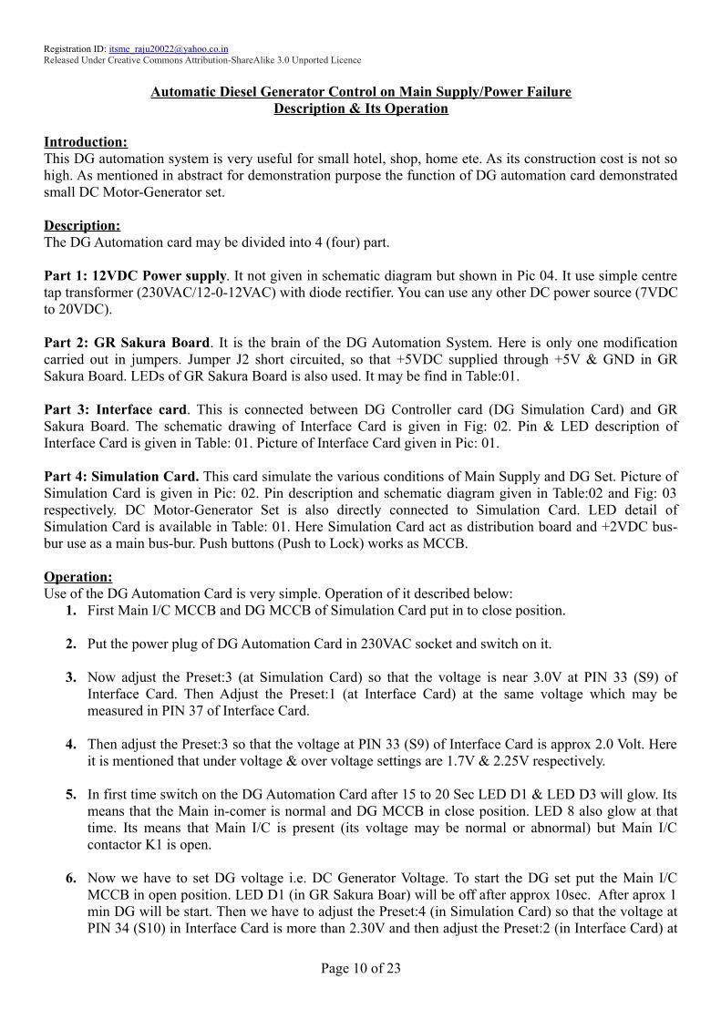
Introduction:
This DG automation system is very useful for small hotel, shop, home ete. As its construction cost is not so
high. As mentioned in abstract for demonstration purpose the function of DG automation card demonstrated
small DC Motor-Generator set.
Description:
The DG Automation card may be divided into 4 (four) part.
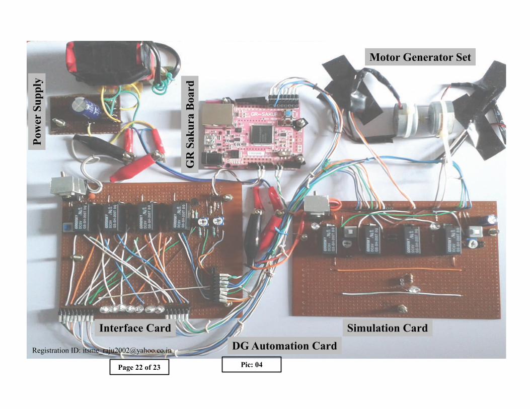
Part 1: 12VDC Power supply. It not given in schematic diagram but shown in Pic 04. It use simple centre
tap transformer (230VAC/12-0-12VAC) with diode rectifier. You can use any other DC power source (7VDC
to 20VDC).
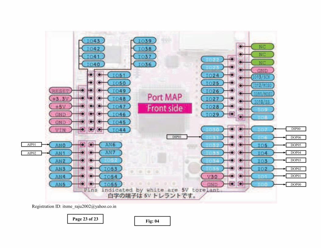
Part 2: GR Sakura Board. It is the brain of the DG Automation System. Here is only one modification
carried out in jumpers. Jumper J2 short circuited, so that +5VDC supplied through +5V & GND in GR
Sakura Board. LEDs of GR Sakura Board is also used. It may be find in Table:01.
Part 3: Interface card. This is connected between DG Controller card (DG Simulation Card) and GR
Sakura Board. The schematic drawing of Interface Card is given in Fig: 02. Pin & LED description of
Interface Card is given in Table: 01. Picture of Interface Card given in Pic: 01.
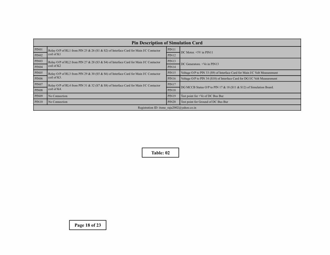
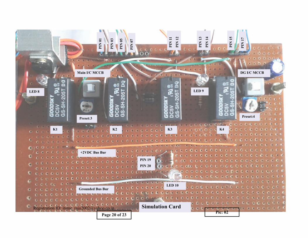
Part 4: Simulation Card. This card simulate the various conditions of Main Supply and DG Set. Picture of
Simulation Card is given in Pic: 02. Pin description and schematic diagram given in Table:02 and Fig: 03
respectively. DC Motor-Generator Set is also directly connected to Simulation Card. LED detail of
Simulation Card is available in Table: 01. Here Simulation Card act as distribution board and +2VDC bus-
bur use as a main bus-bur. Push buttons (Push to Lock) works as MCCB.
Operation:
Use of the DG Automation Card is very simple. Operation of it described below:
1. First Main I/C MCCB and DG MCCB of Simulation Card put in to close position.
2. Put the power plug of DG Automation Card in 230VAC socket and switch on it.
3. Now adjust the Preset:3 (at Simulation Card) so that the voltage is near 3.0V at PIN 33 (S9) of
Interface Card. Then Adjust the Preset:1 (at Interface Card) at the same voltage which may be
measured in PIN 37 of Interface Card.
4. Then adjust the Preset:3 so that the voltage at PIN 33 (S9) of Interface Card is approx 2.0 Volt. Here
it is mentioned that under voltage & over voltage settings are 1.7V & 2.25V respectively.
5. In first time switch on the DG Automation Card after 15 to 20 Sec LED D1 & LED D3 will glow. Its
means that the Main in-comer is normal and DG MCCB in close position. LED 8 also glow at that
time. Its means that Main I/C is present (its voltage may be normal or abnormal) but Main I/C
contactor K1 is open.
6. Now we have to set DG voltage i.e. DC Generator Voltage. To start the DG set put the Main I/C
MCCB in open position. LED D1 (in GR Sakura Boar) will be off after approx 10sec. After aprox 1
min DG will be start. Then we have to adjust the Preset:4 (in Simulation Card) so that the voltage at
PIN 34 (S10) in Interface Card is more than 2.30V and then adjust the Preset:2 (in Interface Card) at
Page 10 of 23
Registration ID: [email protected]
Released Under Creative Commons Attribution-ShareAlike 3.0 Unported Licence
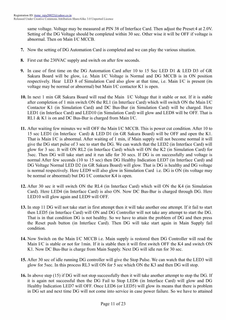
same voltage. Voltage may be measured at PIN 38 of Interface Card. Then adjust the Preset:4 at 2.0V.
Setting of the DG Voltage should be completed within 30 sec. Other wise it will be OFF if voltage is
abnormal. Then on Main I/C MCCB.
7. Now the setting of DG Automation Card is completed and we can play the various situation.
8. First cut the 230VAC supply and switch on after few seconds.
9. In case of first time on the DG Automation Card after 10 to 15 Sec LED D1 & LED D3 of GR
Sakura Board will be glow, i.e. Main I/C Voltage is Normal and DG MCCB is in ON position
respectively. Hear LED 8 of Simulation Card also glow at that time, i.e. Main I/C is present (its
voltage may be normal or abnormal) but Main I/C contactor K1 is open.
10. In next 1 min GR Sakura Board will read the Main I/C Voltage that it stable or not. If it is stable
after completion of 1 min switch ON the RL1 (in Interface Card) which will switch ON the Main I/C
Contactor K1 (in Simulation Card) and DC Bus-Bur (in Simulation Card) will be charged. Here
LED1 (in Interface Card) and LED10 (in Simulation Card) will glow and LED8 will be OFF. That is
RL1 & K1 is on and DC Bus-Bur is charged from Main I/C.
11. After waiting few minutes we will OFF the Main I/C MCCB. This is power cut condition. After 10 to
15 sec LED1 (in Interface Card) & LED D1 (in GR Sakura Board) will be OFF and open the K1.
That is Main I/C is abnormal. After waiting of 1 min, if Main supply will not become normal it will
give the DG start pulse of 3 sec to start the DG. We can watch that the LED2 (in Interface Card) will
glow for 3 sec. It will ON RL2 (in Interface Card) which will ON the K2 (in Simulation Card) for
3sec. Then DG will take start and it run idle for 30 secs. If DG is on successfully and voltage is
normal After few seconds (10 to 15 sec) then DG Healthy Indication LED7 (in Interface Card) and
DG Voltage Normal LED D2 (in GR Sakura Board) will glow. That is DG is healthy and DG voltage
is normal respectively. Here LED9 will also glow in Simulation Card i.e. DG is ON (its voltage may
be normal or abnormal) but DG I/C contactor K4 is open.
12. After 30 sec it will switch ON the RL4 (in Interface Card) which will ON the K4 (in Simulation
Card). Here LED4 (in Interface Card) is also ON. Now DC Bus-Bur is charged through DG. Here
LED10 will glow again and LED9 will OFF.
13. In step 11 DG will not take start in first attempt then it will take another one attempt. If it fail to start
then LED5 (in Interface Card) will ON and DG Controller will not take any attempt to start the DG.
That is in that condition DG is not healthy. So we have to attain the problem of DG and then press
the Reset push button (in Interface Card). Then DG will take start again in Main Supply fail
condition.
14. Now Switch on the Main I/C MCCB i.e. Main supply is restored then DG Controller will read the
Main I/C is stable or not for 1min. If it is stable then it will first switch OFF the K4 and switch ON
K1. Now DC Bus-Bur is charge from Main Supply. Next DG will idle run for 30 sec.
15. After 30 sec of idle running DG controller will give the Stop Pulse. We can watch that the LED3 will
glow for 5sec. In this process RL3 will ON for 5 sec which ON the K3 and then DG will stop.
16. In above step (15) if DG will not stop successfully then it will take another attempt to stop the DG. If
it is again not successful then the DG Fail to Stop LED6 (in Interface Card) will glow and DG
Healthy Indication LED7 will OFF. Once LED6 (or LED5) will glow its means that there is problem
in DG set and next time DG will not come into service in case power failure. So we have to attained
Page 11 of 23

Registration ID: [email protected]
Released Under Creative Commons Attribution-ShareAlike 3.0 Unported Licence
the DG problem and then press the Reset Push Button in Interface Card.
17. There is any other problem aper during DG in service condition i.e. DG MCCB tripped or DG
Voltage become abnormal then K4 will open and DG Fail to Start (LED5) will ON. Here it also
mentioned that if the DG MCCB open before DG start then it not take start.
18. We can make the DG Voltage abnormal by rotating the Preset:4 (rotate anti clockwise make over
voltage and clockwise to under voltage).
19. By rotating the Preset:3 (rotate anti clockwise make over voltage and clockwise to under voltage) in
Simulation Card we can make Main Supply Voltage make abnormal. When Main Supply Voltage
become abnormal then it will also repeat the step 5 to 16.
20. Here it is mentioned that, there is no sensor is connected in DG set to determine it is running or not.
It determine its running conditions by reading DG MCCB status and DG Voltage.
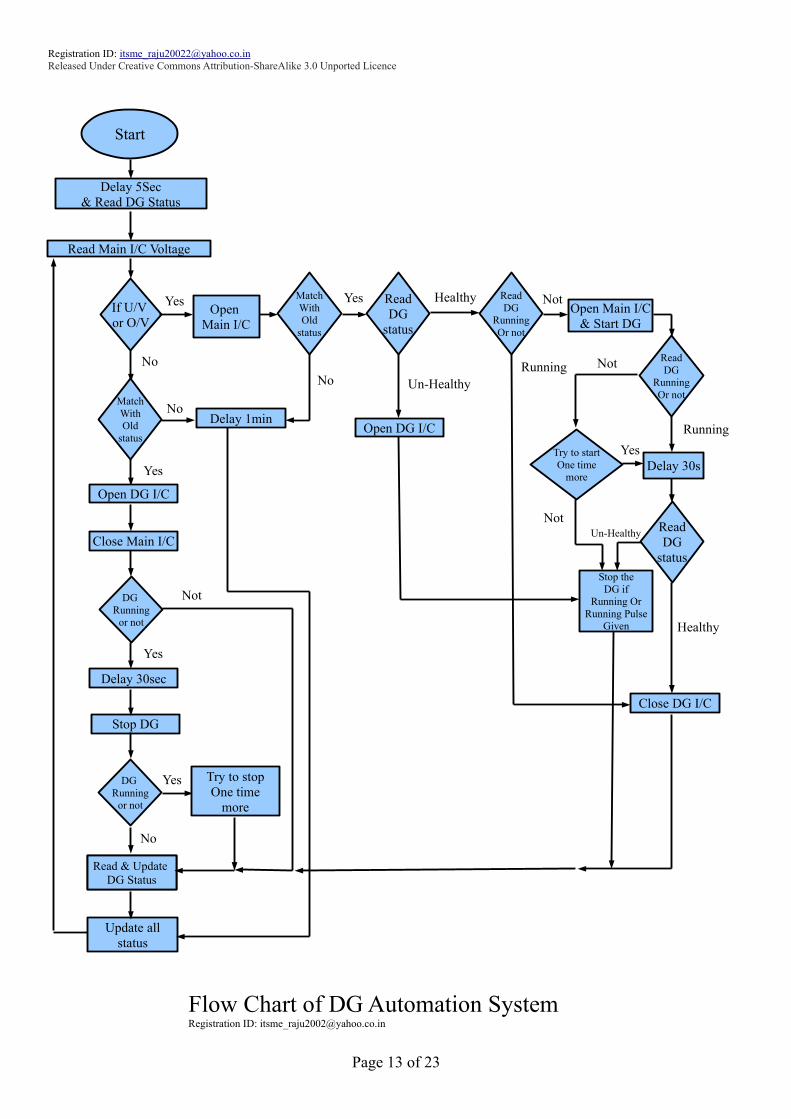
Flowchart and other Schematic Diagrams & pictures given in following pages.
You Tube Video : http://youtu.be/jfffXCIJG48
Page 12 of 23
Registration ID: [email protected]
Released Under Creative Commons Attribution-ShareAlike 3.0 Unported Licence
Page 13 of 23
Delay 5Sec
& Read DG Status
Read Main I/C Voltage
If U/V
or O/V
Match
With
Old
status
Delay 1min
Yes
No
No
Match
With
Old
status
No
Yes
Open DG I/C
Close Main I/C
DG
Running
or not
Delay 30sec
Yes
Stop DG
DG
Running
or not
No
Yes
Update DG
StatusRead & Update
DG Status
Try to stop
One time
more
Update all
status
Not
Open
Main I/C
Yes Read
DG
status
Healthy Read
DG
Running
Or not
NotOpen Main I/C
& Start DG
RunningRead
DG
Running
Or not
Running
Delay 30s
Close DG I/C
Try to start
One time
more
Yes
Not
Not
Open DG I/C
Un-Healthy
Flow Chart of DG Automation SystemRegistration ID: [email protected]
Start
Read
DG
status
Healthy
Un-Healthy
Stop the
DG if
Running Or
Running Pulse
Given

������������� ��� ������
�����
��
�����
��
� ��� �� ���������������������� ��
� ��� ������!� ��
�������� ���
� ��� ������!� ��
���������� ���
��
��
��
��
"#
$ $
"#
�������� ����% �����������������&'�� �����(")
������ ����% �����������������&'�� �����(")
��������(�� ��� ��� �&�������*(")
�+�
��
�+�������� (��
������������� ����*$� ��*,,
������� (�������� ����*$� ��*,,
������������
������������ ������������������������������������������������������������
���������������������� �
��������������������� �
�������������� ������������ �
�������������� ����������� �
�������� ��������������������������
� ����������������� ��������������� �� �
������
�������������

!��"#�$%
�&
'%�(�� '$(��
� �
%�)
*%
�!
%
�%
%�+�,*�
�!
�
��
%�+�,*&
�!
&
�&
%�+�,*-
�!
-
�-
%�+�,
�./�� �./�% �./�� �./�&
�0102
'$(��
!0�%
%+3
!0��
%+3
!0�&
%+3
!0�-
%+3
%+3
& &(�
4050�
!0�"
%+3
*"
$ 6�+3
�./�6
!0�6
%+3
*6
$ 6�+3
�./�$
!0�$
%+3
*$
$ 6�+3
�./�-
17���������� ��
(�����
�/�
� ��
%
%�+
3
%��3
& &(�
4050�
8/�%
1%���������� ��
(�����
/�
� ��
�%�+
3
%��3
& &(�
4050�
8/��
1%%�����
�����1�����
�/�%
�!%%
1% 1�
�!�%
1& 1-1& 1-
�!&%
1$ 16
�!-%
1" 1#
1%������
�����
1�����
��������������
*%9*- ��-$6�5/5�2��������
*$9*6 ��-$"�5/5�2��������
�%9�- 5-��"
�!%9�!- �191:9��$2;�� ����<����$(��������(����� ��=��� �5.>5��������
� ����������������� ��������������� �� �
������
�������������
�/��

���������� ����������������������
/5�% ��������>/�?�/��@����.&%��������1����������=�?��1�@������0102 /5�%!0�6��������)�������1��A�8���� �'$(���/5�%
/5�� ��������.>/�?�./��@������.��������1���������>��.5>.)) /5��
/5�& ��������.>/�?�./�%@������.�%������1���������1�������/��� /5�&!0�"��������: ������=������ �'$(���/5�&
/5�- ��������.>/�?�./��@������.��������1���������1��A�/��� /5�-
/5�$ ��������.>/�?�./�&@������.�&������1���������>��.5>.)) /5�$ � ����.>/�����!%����/5�%B��?1%�B�1�@����1�������������=���������>�������� ����������
+%�/5�6 ��������.>/�?�./�-@������.�$������1���������)�������1�����8���� /5�6
/5�" ��������.>/�?�./�$@������.�6������1���������)�������1��A�8���� /5�" � ����.>/�����!�����/5�&B-�?1&�B�1-@����1�������������=��������1����������� ����������+�/5�# ��������.>/�?�./�6@������.�6������1���������: �������=������ /5�#
/5�7 ��������>/�?�/�%@����.�"������1��������������1����� /5�7 � ����.>/�����!&����/5�$B6�?1$�B�16@����1�������������=��������1��A������� ����������
+&/5%� 5���� ���� /5&�
/5%%!0�%���������>��.5>.))��=������ �'$(���/5%%
/5&% � ����.>/�����!-����/5�"B#�?1"�B�1#@����1�������������=��������>�������� ����������+-/5%� /5&�
/5%&!0����������1�������/��� ��=������ �'$(���/5%&
/5&& (����� �>/������/5�%$�?17@����1�������������=���������>��(����� ���� � �
/5%- /5&- (����� �>/������/5�%6�?1%�@����1�������������=��������>��(����� ���� � �
/5%$!0�&��������1��A�/��� ��=������ �'$(���/5%$
/5&$��������1������>/������/5�%"�B�%#�?1%%�B�1%�@����1�������������=
/5%6 /5&6
/5%"!0�-��������>��.5>.))��=������ �'$(���/5%"
/5&" (����� �>/����8���?8/�%@������1����������>��(����� ���� � �
/5%# /5&# (����� �>/����8�%�?8/��@������1���������>��(����� ���� � �
/5%7!0�$��������)�������1�����8���� �'$(���/5%7
/5&7 5���� ����
/5�� /5-� 5���� ����
!�������������
!0�% !��������� ���� ����= �=������������9��� ��.5>.)) � !0�# !��������1������������= �=��������������� ��.5�C����������=
!0�� !��������� ���� ����= �=�����������1�����A��� � !0�7 !��������1������������= �=������������������5.�!��=
!0�& !��������� ���� ����= �=�����������1��A�A��� !0�%� !��������1������������= �=���������(������C�������� =
!0�- !��������� ���� ����= �=�����������9��� ��.5>.)) � !0���% !�����������18+D�8�����= �=������������9��� ��: ����� �
!0�$ !��������� ���� ����= �=�����������)�������1���� � !0���� !�����������18+D�8�����= �=�����������(����� �5����� �
!0�6 !��������� ���� ����= �=�����������)�������1��A � !0���& !�����������18+D�8�����= �=����������������.5>.)) �
!0�" !��������� ���� ����= �=�����������: ����� � !0���- !�����������18+D�8�����= �=��������5���D�
� ����������������� ��������������� �� �
"�#$�����������%������

!��"#�$%
�&
'%�(�� '$(��
� �
%�)
1�
1%
+% �$
1&
1-
+�
+&%
�6
�#
�"
1$
16
+& �7
1"
1#
+- �%�
����>������
/�
� ��
&�
%+
3
+%% +%%
%+
3
!0�#
'�(����������
%+
3
!0�%�
+�%
��������
���� �����
�������
/�
� ��
-�
%+
3
+-% +-%
%+
3
!0�7
1%%
1%�
&�'($����������
�$9�%� 5-��"
+%9+- �191:9��$2;�� ����<����$(��������(����� ��=��� �5.>5��������
� ����������������� ��������������� �� �
1%�
17
-"���
)
������������)������
���������� ��������&�'($����������
/5�% � ����.>/�����!%������/5��$�B��6�?1%�B�1�@����� ���� ����=���������>�����������
��������+%
/5%%�������� �'$(���/5%%
/5�� /5%�
/5�& � ����.>/�����!�������/5��"�B��#�?1&�B�1-@����� ���� ����=���������>�������������������+�
/5%&���� ����� �'( ���/5%&
/5�- /5%-
/5�$ � ����.>/�����!&������/5��7�B�&��?1$�B�16@����� ���� ����=���������>�����������
��������+&
/5%$ (����� �.>/����/5�&&�?17@����� ���� ����=���������>��(����� ���� � �
/5�6 /5%6 (����� �.>/����/5�&-�?1%�@����� ���� ����=��������>��(����� ���� � �
/5�" � ����.>/�����!-������/5�&%�B�&��?1"�B�1#@����� ���� ����=���������>�������������������+-
/5%"��������1������.>/����/5�%"�B�%#�?1%%�B�1%�@����1�������������=
/5�# /5%#
/5�7 5���� ���� /5%7 2 ���A��������'( ��������������
/5%� 5���� ���� /5�� 2 ���A������������=��������������
� ����������������� ��������������� �� �
"�#$�����
������*������

��+���
��+���
��+���
��+���
��+���
��+��%
��+��)
��+��*
��+��,
!����
!����
!����
!����
!����
!���%
!���)
��+���
��+��%
��+��)
��+��*
��+��,
��+���
��+���
��+���
��+���
��+���
��+���
��+��%
��+��)
��+��*
��������������
����� �
� �
�������� ��������
� ����������������� ��������������� �� �
�������������,������
��+���
��+���
��+���
��+��)
��+���
��+���
��+���
��+���
��+���
��+��)
��+��,
��+���
-�.����(���(�
/��(������(���(�!����
!��* !��,
�/��0������
!��*
��
������0������
�� �� ��
����������������
&�'($����������� ����������������� ��������������� �� ��������
�������������

�������� ���� �����
��������9� ������1 �
� ����������������� ��������������� �� �
�������
�������������
�������������� &�'($����������
������/���������&��
��1���&( $2
/�&�3(��������
�/�4(��'����������� ����������������� ��������������� �� �
��������������������
������
�./��
�./�%
�./��
�./�&
�./�-
�./�$
�./�6
�/��
�/�%
8/�%
8/��
�������������
� ����������������� ��������������� �� �