renewable and sustainable energy reviews - ernetcgpl.iisc.ernet.in/dasappa/img/pdf/journals/solid...
TRANSCRIPT
Renewable and Sustainable Energy Reviews 60 (2016) 450–463
Contents lists available at ScienceDirect
Renewable and Sustainable Energy Reviews
http://d1364-03
n Corrfax: þ9
E-m
journal homepage: www.elsevier.com/locate/rser
Solid oxide fuel cell operating with biomass derived producer gas:Status and challenges
Monikankana Sharma, Rakesh N, S. Dasappa n
Centre for Sustainable Technologies, Indian Institute of Science, Bangalore 560012, India
a r t i c l e i n f o
Article history:Received 25 June 2015Received in revised form26 December 2015Accepted 13 January 2016
Keywords:Biomass gasificationProducer gasSOFCTarCarbon depositionContaminantsCermet
x.doi.org/10.1016/j.rser.2016.01.07521/& 2016 Elsevier Ltd. All rights reserved.
esponding author. Tel.: þ91 80 23600536; þ1 80 2360 0683.ail address: [email protected] (S. Das
a b s t r a c t
Solid oxide fuel cell as a conversion device is finding importance in the energy sector due to its highefficiency, low emissions and fuel flexibility. The use of producer gas as a fuel is gaining importance dueto certain advantages over the conventional fuels while challenges lie in its usage due to the inherentcontaminants present. This paper consolidates the efforts carried out using fossil fuels and highlights thechallenges, and further, the progress made in the use of producer gas is critically examined. The effects ofcontaminants such as tar, particulate matter, H2S etc. on anode materials are highlighted, and thepublished results are consolidated to examine whether the maximum tolerance limits of the con-taminants be identified. However, it is observed that due to many inexorable factors viz., differences inthe electrode material, microstructure, diverse operating conditions, the conclusions obtained are diverseand it is difficult to predict the general behavior of a particular contaminant. The need for a compre-hensive study having both experimental and theoretical components focusing on the role of con-taminants under the same operating conditions and using the same materials is highlighted as a majorconclusion of this study.
& 2016 Elsevier Ltd. All rights reserved.
Contents
1. Introduction . . . . . . . . . . . . . . . . . . . . . . . . . . . . . . . . . . . . . . . . . . . . . . . . . . . . . . . . . . . . . . . . . . . . . . . . . . . . . . . . . . . . . . . . . . . . . . . . . . . . . . . . 4502. Solid oxide fuel cell with PG: electrochemical reactions . . . . . . . . . . . . . . . . . . . . . . . . . . . . . . . . . . . . . . . . . . . . . . . . . . . . . . . . . . . . . . . . . . . . . 4513. Material for SOFC components . . . . . . . . . . . . . . . . . . . . . . . . . . . . . . . . . . . . . . . . . . . . . . . . . . . . . . . . . . . . . . . . . . . . . . . . . . . . . . . . . . . . . . . . . 4524. Gasification: technology and issues . . . . . . . . . . . . . . . . . . . . . . . . . . . . . . . . . . . . . . . . . . . . . . . . . . . . . . . . . . . . . . . . . . . . . . . . . . . . . . . . . . . . . 453
4.1. Gasification process . . . . . . . . . . . . . . . . . . . . . . . . . . . . . . . . . . . . . . . . . . . . . . . . . . . . . . . . . . . . . . . . . . . . . . . . . . . . . . . . . . . . . . . . . . . . 4534.2. Gasification systems . . . . . . . . . . . . . . . . . . . . . . . . . . . . . . . . . . . . . . . . . . . . . . . . . . . . . . . . . . . . . . . . . . . . . . . . . . . . . . . . . . . . . . . . . . . 4534.3. Some aspects on gas quality for SOFC application . . . . . . . . . . . . . . . . . . . . . . . . . . . . . . . . . . . . . . . . . . . . . . . . . . . . . . . . . . . . . . . . . . . . 4544.4. Gasification system with low tar and particulate: experience at the Indian Institute of Science (IISc). . . . . . . . . . . . . . . . . . . . . . . . . . . 454
5. Progress in PG fueled SOFC technology . . . . . . . . . . . . . . . . . . . . . . . . . . . . . . . . . . . . . . . . . . . . . . . . . . . . . . . . . . . . . . . . . . . . . . . . . . . . . . . . . . 4555.1. Parametric studies . . . . . . . . . . . . . . . . . . . . . . . . . . . . . . . . . . . . . . . . . . . . . . . . . . . . . . . . . . . . . . . . . . . . . . . . . . . . . . . . . . . . . . . . . . . . . 4555.2. Effect of contaminants of syngas on SOFC . . . . . . . . . . . . . . . . . . . . . . . . . . . . . . . . . . . . . . . . . . . . . . . . . . . . . . . . . . . . . . . . . . . . . . . . . . 457
5.2.1. Studies on tar. . . . . . . . . . . . . . . . . . . . . . . . . . . . . . . . . . . . . . . . . . . . . . . . . . . . . . . . . . . . . . . . . . . . . . . . . . . . . . . . . . . . . . . . . . 4575.2.2. Studies on particulate matter, H2S HCl, NH3. . . . . . . . . . . . . . . . . . . . . . . . . . . . . . . . . . . . . . . . . . . . . . . . . . . . . . . . . . . . . . . . . . 457
5.3. Theoretical studies involving performance evaluation of PG/syngas fed SOFC. . . . . . . . . . . . . . . . . . . . . . . . . . . . . . . . . . . . . . . . . . . . . . 4595.4. Performance comparison of SOFC with different fuels . . . . . . . . . . . . . . . . . . . . . . . . . . . . . . . . . . . . . . . . . . . . . . . . . . . . . . . . . . . . . . . . 460
6. Conclusions . . . . . . . . . . . . . . . . . . . . . . . . . . . . . . . . . . . . . . . . . . . . . . . . . . . . . . . . . . . . . . . . . . . . . . . . . . . . . . . . . . . . . . . . . . . . . . . . . . . . . . . . 461References . . . . . . . . . . . . . . . . . . . . . . . . . . . . . . . . . . . . . . . . . . . . . . . . . . . . . . . . . . . . . . . . . . . . . . . . . . . . . . . . . . . . . . . . . . . . . . . . . . . . . . . . . . . . . 461
91 80 22932338;
appa).
1. Introduction
Rising energy consumptions and higher emissions from com-bustion devices operating with conventional fuels demand
M. Sharma et al. / Renewable and Sustainable Energy Reviews 60 (2016) 450–463 451
alternate energy sources, and Solid oxide fuel cell (SOFC) being anefficient, environment friendly, fuel flexible energy conversiontechnology is able to attract the attention of researchers [1]. Overthe last two decades, significant progress has been made on SOFC,especially on the materials to support high temperature operationsand different fuels [2]. However, commercialization of the tech-nology is hindered by a few important factors, and the productionand storage of hydrogen (H2) which is being considered as an idealfuel are major challenges [3]. As an alternative, the use of renewablefuels is desirable, and producer gas (PG)/syngas generated frombiomass has received widespread attention due to its carbon neu-trality nature [4].
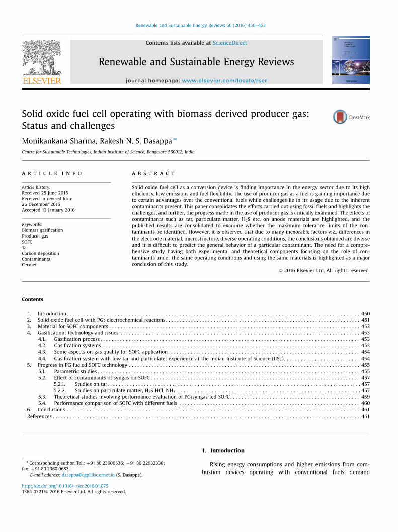
Biomass generates both liquid and gaseous fuels; however theconversion efficiency of biomass to liquid is low (Fig. 1) [5], andthis makes the use of gaseous fuel more prevalent. IC engine is themost common route due to the simple design and lower capitalcost. Significant efforts have gone on using diesel engine on dualfuel mode [6–8] and gas engines on PG alone mode [9–12]. It mustbe emphasized that significant research towards operating theengine with PG has been carried out and the required gas qualityfor engine application has been established. Attempts have also
Fig. 1. Comparison of biomass to fuel efficiency in the bio-refineries or powerstations [5].
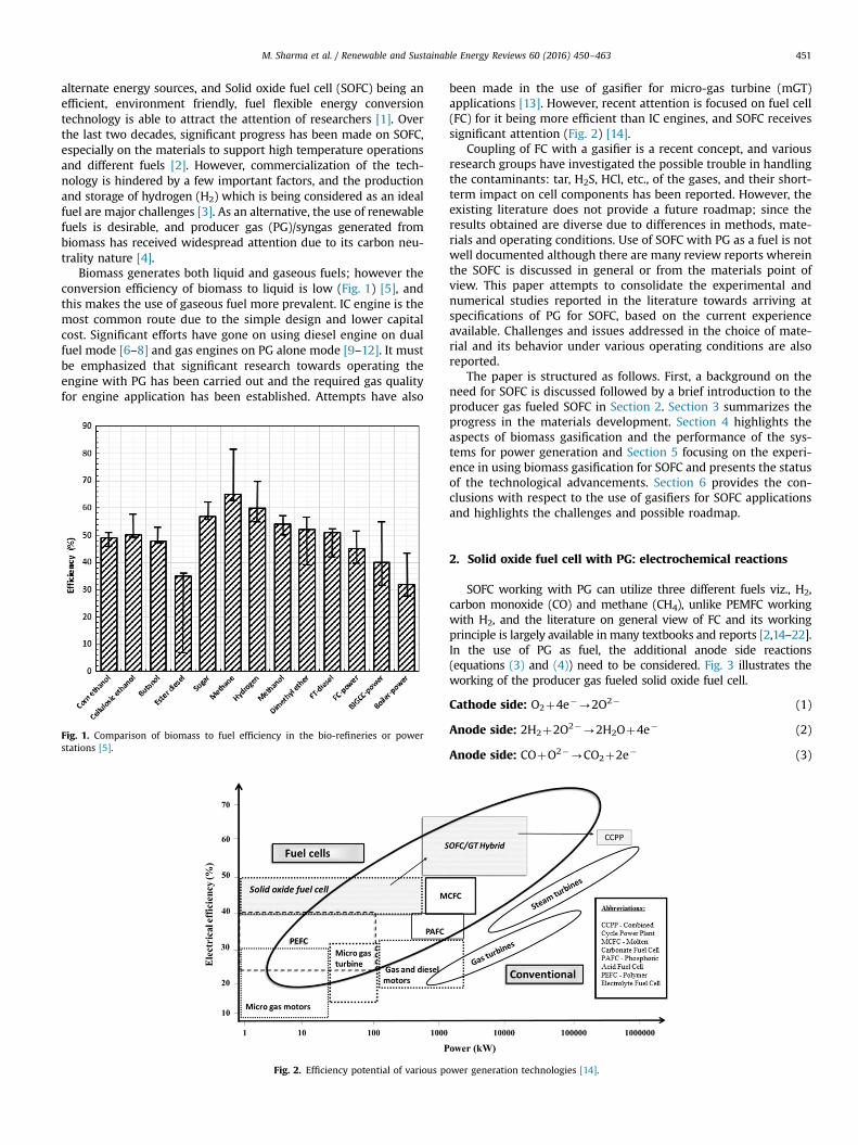
Fig. 2. Efficiency potential of various po
been made in the use of gasifier for micro-gas turbine (mGT)applications [13]. However, recent attention is focused on fuel cell(FC) for it being more efficient than IC engines, and SOFC receivessignificant attention (Fig. 2) [14].
Coupling of FC with a gasifier is a recent concept, and variousresearch groups have investigated the possible trouble in handlingthe contaminants: tar, H2S, HCl, etc., of the gases, and their short-term impact on cell components has been reported. However, theexisting literature does not provide a future roadmap; since theresults obtained are diverse due to differences in methods, mate-rials and operating conditions. Use of SOFC with PG as a fuel is notwell documented although there are many review reports whereinthe SOFC is discussed in general or from the materials point ofview. This paper attempts to consolidate the experimental andnumerical studies reported in the literature towards arriving atspecifications of PG for SOFC, based on the current experienceavailable. Challenges and issues addressed in the choice of mate-rial and its behavior under various operating conditions are alsoreported.
The paper is structured as follows. First, a background on theneed for SOFC is discussed followed by a brief introduction to theproducer gas fueled SOFC in Section 2. Section 3 summarizes theprogress in the materials development. Section 4 highlights theaspects of biomass gasification and the performance of the sys-tems for power generation and Section 5 focusing on the experi-ence in using biomass gasification for SOFC and presents the statusof the technological advancements. Section 6 provides the con-clusions with respect to the use of gasifiers for SOFC applicationsand highlights the challenges and possible roadmap.
2. Solid oxide fuel cell with PG: electrochemical reactions
SOFC working with PG can utilize three different fuels viz., H2,carbon monoxide (CO) and methane (CH4), unlike PEMFC workingwith H2, and the literature on general view of FC and its workingprinciple is largely available in many textbooks and reports [2,14–22].In the use of PG as fuel, the additional anode side reactions(equations (3) and (4)) need to be considered. Fig. 3 illustrates theworking of the producer gas fueled solid oxide fuel cell.
Cathode side: O2þ4e�-2O2� (1)
Anode side: 2H2þ2O2�-2H2Oþ4e� (2)
Anode side: COþO2�-CO2þ2e� (3)
wer generation technologies [14].
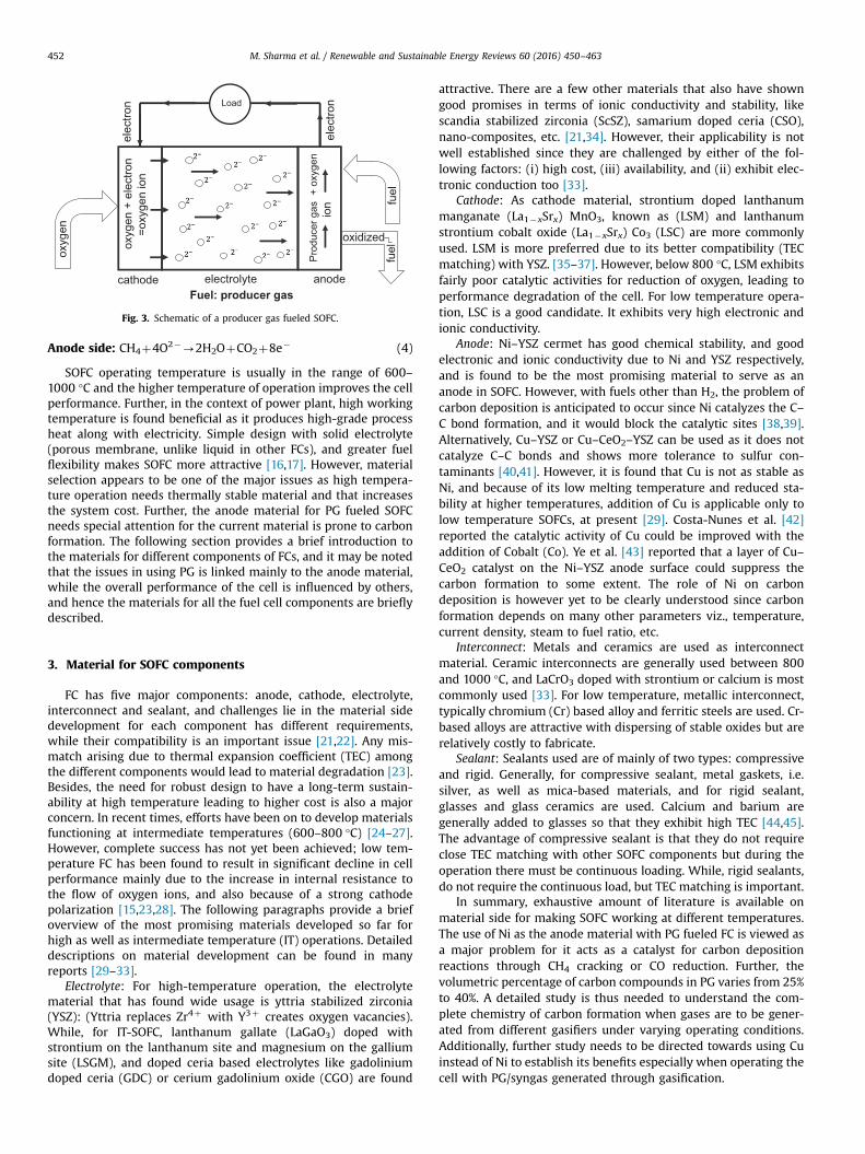
cathode anode
oxyg
en
elec
tron
fuel
oxidized
elec
tron Load
electrolyte
Pro
duce
r gas
+ o
xyge
n io
n
oxyg
en +
ele
ctro
n=o
xyge
n io
n
fuel
Fuel: producer gas
Fig. 3. Schematic of a producer gas fueled SOFC.
M. Sharma et al. / Renewable and Sustainable Energy Reviews 60 (2016) 450–463452
Anode side: CH4þ4O2�-2H2OþCO2þ8e� (4)
SOFC operating temperature is usually in the range of 600–1000 °C and the higher temperature of operation improves the cellperformance. Further, in the context of power plant, high workingtemperature is found beneficial as it produces high-grade processheat along with electricity. Simple design with solid electrolyte(porous membrane, unlike liquid in other FCs), and greater fuelflexibility makes SOFC more attractive [16,17]. However, materialselection appears to be one of the major issues as high tempera-ture operation needs thermally stable material and that increasesthe system cost. Further, the anode material for PG fueled SOFCneeds special attention for the current material is prone to carbonformation. The following section provides a brief introduction tothe materials for different components of FCs, and it may be notedthat the issues in using PG is linked mainly to the anode material,while the overall performance of the cell is influenced by others,and hence the materials for all the fuel cell components are brieflydescribed.
3. Material for SOFC components
FC has five major components: anode, cathode, electrolyte,interconnect and sealant, and challenges lie in the material sidedevelopment for each component has different requirements,while their compatibility is an important issue [21,22]. Any mis-match arising due to thermal expansion coefficient (TEC) amongthe different components would lead to material degradation [23].Besides, the need for robust design to have a long-term sustain-ability at high temperature leading to higher cost is also a majorconcern. In recent times, efforts have been on to develop materialsfunctioning at intermediate temperatures (600–800 °C) [24–27].However, complete success has not yet been achieved; low tem-perature FC has been found to result in significant decline in cellperformance mainly due to the increase in internal resistance tothe flow of oxygen ions, and also because of a strong cathodepolarization [15,23,28]. The following paragraphs provide a briefoverview of the most promising materials developed so far forhigh as well as intermediate temperature (IT) operations. Detaileddescriptions on material development can be found in manyreports [29–33].
Electrolyte: For high-temperature operation, the electrolytematerial that has found wide usage is yttria stabilized zirconia(YSZ): (Yttria replaces Zr4þ with Y3þ creates oxygen vacancies).While, for IT-SOFC, lanthanum gallate (LaGaO3) doped withstrontium on the lanthanum site and magnesium on the galliumsite (LSGM), and doped ceria based electrolytes like gadoliniumdoped ceria (GDC) or cerium gadolinium oxide (CGO) are found
attractive. There are a few other materials that also have showngood promises in terms of ionic conductivity and stability, likescandia stabilized zirconia (ScSZ), samarium doped ceria (CSO),nano-composites, etc. [21,34]. However, their applicability is notwell established since they are challenged by either of the fol-lowing factors: (i) high cost, (iii) availability, and (ii) exhibit elec-tronic conduction too [33].
Cathode: As cathode material, strontium doped lanthanummanganate (La1�xSrx) MnO3, known as (LSM) and lanthanumstrontium cobalt oxide (La1�xSrx) Co3 (LSC) are more commonlyused. LSM is more preferred due to its better compatibility (TECmatching) with YSZ. [35–37]. However, below 800 °C, LSM exhibitsfairly poor catalytic activities for reduction of oxygen, leading toperformance degradation of the cell. For low temperature opera-tion, LSC is a good candidate. It exhibits very high electronic andionic conductivity.
Anode: Ni–YSZ cermet has good chemical stability, and goodelectronic and ionic conductivity due to Ni and YSZ respectively,and is found to be the most promising material to serve as ananode in SOFC. However, with fuels other than H2, the problem ofcarbon deposition is anticipated to occur since Ni catalyzes the C–C bond formation, and it would block the catalytic sites [38,39].Alternatively, Cu–YSZ or Cu–CeO2–YSZ can be used as it does notcatalyze C–C bonds and shows more tolerance to sulfur con-taminants [40,41]. However, it is found that Cu is not as stable asNi, and because of its low melting temperature and reduced sta-bility at higher temperatures, addition of Cu is applicable only tolow temperature SOFCs, at present [29]. Costa-Nunes et al. [42]reported the catalytic activity of Cu could be improved with theaddition of Cobalt (Co). Ye et al. [43] reported that a layer of Cu–CeO2 catalyst on the Ni–YSZ anode surface could suppress thecarbon formation to some extent. The role of Ni on carbondeposition is however yet to be clearly understood since carbonformation depends on many other parameters viz., temperature,current density, steam to fuel ratio, etc.
Interconnect: Metals and ceramics are used as interconnectmaterial. Ceramic interconnects are generally used between 800and 1000 °C, and LaCrO3 doped with strontium or calcium is mostcommonly used [33]. For low temperature, metallic interconnect,typically chromium (Cr) based alloy and ferritic steels are used. Cr-based alloys are attractive with dispersing of stable oxides but arerelatively costly to fabricate.
Sealant: Sealants used are of mainly of two types: compressiveand rigid. Generally, for compressive sealant, metal gaskets, i.e.silver, as well as mica-based materials, and for rigid sealant,glasses and glass ceramics are used. Calcium and barium aregenerally added to glasses so that they exhibit high TEC [44,45].The advantage of compressive sealant is that they do not requireclose TEC matching with other SOFC components but during theoperation there must be continuous loading. While, rigid sealants,do not require the continuous load, but TEC matching is important.
In summary, exhaustive amount of literature is available onmaterial side for making SOFC working at different temperatures.The use of Ni as the anode material with PG fueled FC is viewed asa major problem for it acts as a catalyst for carbon depositionreactions through CH4 cracking or CO reduction. Further, thevolumetric percentage of carbon compounds in PG varies from 25%to 40%. A detailed study is thus needed to understand the com-plete chemistry of carbon formation when gases are to be gener-ated from different gasifiers under varying operating conditions.Additionally, further study needs to be directed towards using Cuinstead of Ni to establish its benefits especially when operating thecell with PG/syngas generated through gasification.
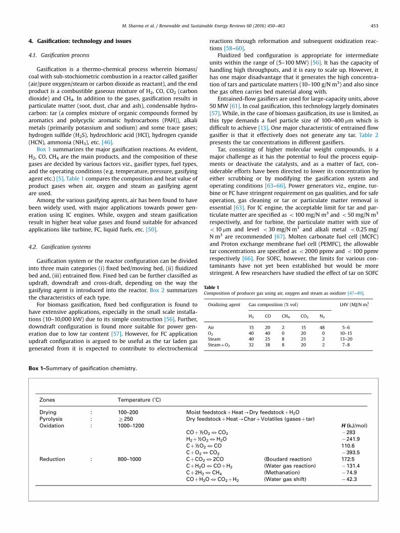
Table 1Composition of producer gas using air, oxygen and steam as oxidizer [47–49].
Oxidizing agent Gas composition (% vol) LHV (MJ/N m3)
H2 CO CH4 CO2 N2
Air 15 20 2 15 48 5–6O2 40 40 0 20 0 10–15Steam 40 25 8 25 2 13–20SteamþO2 32 38 8 20 2 7–8
M. Sharma et al. / Renewable and Sustainable Energy Reviews 60 (2016) 450–463 453
4. Gasification: technology and issues
4.1. Gasification process
Gasification is a thermo-chemical process wherein biomass/coal with sub-stochiometric combustion in a reactor called gasifier(air/pure oxygen/steam or carbon dioxide as reactant), and the endproduct is a combustible gaseous mixture of H2, CO, CO2 (carbondioxide) and CH4. In addition to the gases, gasification results inparticulate matter (soot, dust, char and ash), condensable hydro-carbon: tar (a complex mixture of organic compounds formed byaromatics and polycyclic aromatic hydrocarbons (PAH)), alkalimetals (primarily potassium and sodium) and some trace gases;hydrogen sulfide (H2S), hydrochloric acid (HCl), hydrogen cyanide(HCN), ammonia (NH3), etc. [46].
Box 1 summarizes the major gasification reactions. As evident,H2, CO, CH4 are the main products, and the composition of thesegases are decided by various factors viz., gasifier types, fuel types,and the operating conditions (e.g. temperature, pressure, gasifyingagent etc.) [5]. Table 1 compares the composition and heat value ofproduct gases when air, oxygen and steam as gasifying agentare used.
Among the various gasifying agents, air has been found to havebeen widely used, with major applications towards power gen-eration using IC engines. While, oxygen and steam gasificationresult in higher heat value gases and found suitable for advancedapplications like turbine, FC, liquid fuels, etc. [50].
4.2. Gasification systems
Gasification system or the reactor configuration can be dividedinto three main categories (i) fixed bed/moving bed, (ii) fluidizedbed and, (iii) entrained flow. Fixed bed can be further classified asupdraft, downdraft and cross-draft, depending on the way thegasifying agent is introduced into the reactor. Box 2 summarizesthe characteristics of each type.
For biomass gasification, fixed bed configuration is found tohave extensive applications, especially in the small scale installa-tions (10–10,000 kW) due to its simple construction [56]. Further,downdraft configuration is found more suitable for power gen-eration due to low tar content [57]. However, for FC applicationupdraft configuration is argued to be useful as the tar laden gasgenerated from it is expected to contribute to electrochemical
Box 1–Summary of gasification chemistry.
Zones Temperature (˚C)
Drying : 100–200 Moist feePyrolysis : Z250 Dry feedOxidation : 1000–1200
COþ½OH2þ½O2
Cþ½O23CþO23
Reduction : 800–1000 CþCO23CþH2O3Cþ2H23COþH2O
reactions through reformation and subsequent oxidization reac-tions [58–60].
Fluidized bed configuration is appropriate for intermediateunits within the range of (5–100 MW) [56]. It has the capacity ofhandling high throughputs, and it is easy to scale up. However, ithas one major disadvantage that it generates the high concentra-tion of tars and particulate matters (10–100 g/N m3) and also sincethe gas often carries bed material along with.
Entrained-flow gasifiers are used for large-capacity units, above50 MW [61]. In coal gasification, this technology largely dominates[57]. While, in the case of biomass gasification, its use is limited, asthis type demands a fuel particle size of 100–400 mm which isdifficult to achieve [13]. One major characteristic of entrained flowgasifier is that it effectively does not generate any tar. Table 2presents the tar concentrations in different gasifiers.
Tar, consisting of higher molecular weight compounds, is amajor challenge as it has the potential to foul the process equip-ments or deactivate the catalysts, and as a matter of fact, con-siderable efforts have been directed to lower its concentration byeither scrubbing or by modifying the gasification system andoperating conditions [63–66]. Power generators viz., engine, tur-bine or FC have stringent requirement on gas qualities, and for safeoperation, gas cleaning or tar or particulate matter removal isessential [63]. For IC engine, the acceptable limit for tar and par-ticulate matter are specified as o100 mg/N m3 and o50 mg/N m3
respectively, and for turbine, the particulate matter with size ofo10 mm and level o30 mg/N m3 and alkali metal o0.25 mg/N m3 are recommended [67]. Molten carbonate fuel cell (MCFC)and Proton exchange membrane fuel cell (PEMFC), the allowabletar concentrations are specified as o2000 ppmv and o100 ppmvrespectively [66]. For SOFC, however, the limits for various con-taminants have not yet been established but would be morestringent. A few researchers have studied the effect of tar on SOFC
dstockþHeat-Dry feedstockþH2OstockþHeat-CharþVolatiles (gasesþtar)
H (kJ/mol)
23CO2 �2833H2O �241.9CO 110.6
CO2 �393.52CO (Boudard reaction) 172:5COþH2 (Water gas reaction) �131.4CH4 (Methanation) �74.93CO2þH2 (Water gas shift) �42.3
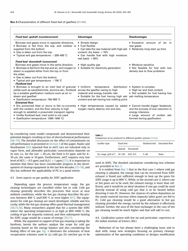
Box 2–Characteristics of different fixed bed of gasifiers [51–55].
Fixed bed: updraft (countercurrent) Advantages Disadvantages
Biomass and gases move in opposite directions. � Simple design� Fuel flexible� Can take the raw material with high ashcontent: dry basis o15%� Can handle fuel with high moisture:wet basis o50%
� Excessive amount of tar inraw gases� Relatively long start up time
� Biomass is fed from the top, and oxidizer issupplied from the bottom� Gas is taken out from the top.� Typical exit gas temperature: �200–400 ˚C
Fixed bed: downdraft (concurrent)
Biomass and gases move in the same direction. � High quality gas� Suitable for electricity generation
� Moisture sensitive� Not feasible for fuel with lowdensity due to flow problems
� Biomass is fed from the top and air, and oxygen orsteam is supplied either from the top or fromthe sides.� Gas is taken out from the bottom.� Typical exit gas temperature: �700 ˚CFluidized bed
� Biomass is brought to an inert bed of granularsolids such as sand/dolomite, alumina etc., fluidizedby a suitable gasification medium such as air orsteam and gasified� Gasification temperature: 750–900 ˚C
� Uniform temperature distributionacross the gasifier owing to highmaterial and energy transfer rate� Suitable for the fuel having high ashcontent and ash having low melting point
� System is complex� High tar and dust content� Not suitable for fuel having lowash melting temperature
Entrained flow� Dry pulverized feed or slurry is fed co-currentlywith the oxidant, and the flow velocity is highenough to establish a pneumatic transport regime� Unlike fluidized bed, inert solid is not used� Gasification temperature: 1300–1400 ˚C)
� High temperatures caused by addedoxygen nearly destroy oils and tars.
� Cannot handle bigger feedstock,and the process of size reduction isenergy intensive� Large amount of molten ashformed during gasification
Table 2Comparison of tar produced in different gasifier systems [51,62].
Gasifier type Fixed bed Fluidised bed Entrained flow
Updraft Downdraft
Tar range (g/N m3) 10–150 0.01–0.5 5–40 None
M. Sharma et al. / Renewable and Sustainable Energy Reviews 60 (2016) 450–463454
by considering some model compounds and demonstrated theirpotential dangers resulting in loss of electrochemical performance[68–70]. The detailed discussion on the effect of contaminants oncell performance is presented in Section 5 of this paper. Hasler andNussbaumer [63] reported that in mGT, tars are tolerated only invapor form, and allowable particulate concentration depends onits size, i.e., for the size 420 mm, the limit is 0.1 ppm, and for 4–10 mm, the same is 10 ppm. Furthermore, mGT requires very lowlevel of HCl (o0.5 ppm) and H2S (o1 ppm) [71]. It is important tomention that there has been considerable progress in the devel-opment of cleanup equipment in the last few decades [72–74], andthis has widened the applicability of PG to a good extent.
4.3. Some aspects on gas quality for SOFC application
Depending upon the process temperature range, the gascleanup technologies are classified either hot or cold. Cold gascleanup generally describes the processes that occur at nearambient conditions, while the hot gas cleanup describes the pro-cess between 400 °C and1300 °C or even higher [67]. The equip-ments for cold gas cleanup are much developed, reliable and lesscostly, while the hot gas cleanup offers good thermal management[58,75,76]. Many researchers argued that for a system like SOFCwhere the operating temperature is as high as 800–1000 °C, thecooling of gas for impurity removal, and then subsequent heatingfor SOFC usage would be a waste of energy [76,77].
While, the argument in support of hot gas cleaning is taking theforefront, herein the authors analyze the scope for cold gascleaning based on the energy balance and also considering thefouling effect of raw gas. Fig. 4 illustrates the schematic of heatrecuperation schemes used in (a) cold gas (b) raw/hot gas to be
used in SOFC. The detailed calculations considering two schemesare provided in Box 3.
It is evident from Box 3 that in the first case 1 where cold gascleaning is adopted, the energy that can be recovered from SOFCexhaust is found just sufficient enough to heat up the gases forSOFC usage is up to 800 °C. While, in the second case 2, where rawor hot gases are to be used, the exhaust energy is more than suf-ficient, and it would be an ideal situation if raw gas could be useddirectly instead of using cold gas that is to be heated beforediverting it into FC. However, the chances of carbon deposition onthe anode material increase when impurity laden gases are fed toFC. Cold gas cleaning would be a good alternative to hot gascleaning provided the energy carried by the exhaust is effectivelyutilized. Further, the area of the heat exchanger in the case of hotgas cleaning would be much higher and that will add to cost.
4.4. Gasification system with low tar and particulate: experience atthe Indian Institute of Science (IISc)
Reduction of tar has always been a challenging issue, and todeal with, many new strategies focusing on primary cleanup:optimization of the operating conditions or designs modification
Fig. 4. Schematic showing heat recuperation schemes in SOFC using (a) cold gas and (b) raw/hot gas.
Box 3–Analysis of energy effectiveness of cold and raw/hot gasesfrom gasifier to use in SOFC.
Case 1 Case 2
Cold gascleaning
Hot gascleaning
Gasifier exit temperature : 500 ˚C 500 ˚CTemperature after scrubbingand cooling
: 30 ˚C –
Heat in the exhaust 2025 kJ 2025 kJHeat exchangereffectiveness: (assumed)
: 0.5 0.5
Heat available to preheat thegas for SOFC
: 1012.5 kJ 1012.5 kJ
Energy required for heatinggases up to 800 ˚C
: 1001 kJ 643.5 kJ
Surplus energy : 11.5 kJ 369 kJ
Fig. 5. A schematic representation of various parameters affecting cellperformance.
M. Sharma et al. / Renewable and Sustainable Energy Reviews 60 (2016) 450–463 455
has come into play [64]. Among the new designs, the two stagedgasification system; with separate pyrolysis and reduction zonesand the two staged air entry has received broad attention [78–80].The latter design developed at Indian Institute of Science (IISc)seems more promising from technical as well as economical pointof view, and proven effective in fields [81–86]. This system canaccommodate both woody and non-woody biomass and gasifythem with an efficiency of �80%. The average gas composition ofthis systemwith air as oxidizing agent is found as H2: 1971%; CO:1971%; CH4: 1.5%; CO2: 1271%; H2O: 270.5%, and the meancalorific value 4.670.2 MJ/kg.
The unique feature of the IISc gasification system is that it hasdual air entry; one from the nozzle and the other from the top ofthe reactor. The open top permits the reaction front to moveupwards creating a second high temperature zone ensuring highresidence time for the gases at elevated temperatures that furtherfacilitates tar cracking due to the simultaneous action of heat andcatalytic action of hot char. Detailed measurements have shownthat the fraction of higher hydrocarbons in the hot gas in this opentop design is lower than that of a classical closed top design. In theraw gas, the respective tar and particulate concentrations arereported to be �150 mg/m3, 1000 mg/m3 respectively, while thesame in the cold gas o2 mg/m3 and 10 mg/m3 [48,85]. These lowlevels of tar and particulates are the main characteristic featuresthat allow the generated gases to use in IC engine, or gas turbine
that has stringent norms as stated before. FC has not yet beentested with the gases from this system but can be a good optionprovided the trace elements remains ineffective to anode materi-als. The following section consolidates the findings of variousresearchers who studied the effect of contaminants of PG onperformance of SOFC.
5. Progress in PG fueled SOFC technology
Coupling of biomass gasification to SOFC is a relatively newconcept and predominantly studied in theory, with a few experi-mental investigations showing the feasibility of the concept [87–90]. Most theoretical studies aimed at performance evaluation ofthe system through thermodynamic analysis considering variousparameters responsible while experimental investigations focusmainly on the effects of contaminants on the cell performance toestablish the minimum allowable limit. Gasification parameterssuch as steam to carbon ratio, steam to air ratio, temperature, etc.which have influence on gas composition and ultimately the cellperformance is also studied by a few researchers [91–93]. Thefollowing section includes a review of the work conducted so far,considering different aspects, right from parametric studies toultimate performance analysis in terms of efficiency.
5.1. Parametric studies
Performance of SOFC is dependent on many parameters andsome of them are influenced by the gasification process. Types ofgasifier, oxidizing agent, operating temperature etc., have a stronginfluence on the gas composition and it ultimately affects celloutput. Fig. 5 illustrates a few input parameters that are found tohave a strong effect on the cell performance [94–96]. A fewresearchers have studied the parameters affecting gasification as
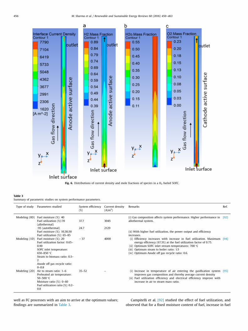
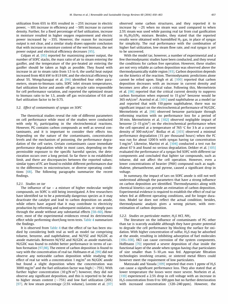
Fig. 6. Distributions of current density and mole fractions of species in a H2 fueled SOFC.
Table 3Summary of parametric studies on system performance parameters.
Type of study Parameters studied System efficiency(%)
Current density(A/m2)
Remarks Ref.
Modeling (0D) Fuel moisture (%): 40 (i) Gas composition affects system performance. Higher performance inallothermal system.
[92]Fuel utilization (%):70(allothermal)
37.7 3045
:95 (autothermal) 24.7 2129Fuel moisture (%): 10,30,50 (ii) With higher fuel utilization, the power output and efficiency
increases.Fuel utilization (%): 65–85Modeling (1D) Fuel moisture (%): 20 �37 4000 (i) Efficiency increases with increase in fuel utilization. Maximum
exergy efficiency (67.3%) at the fuel utilization factor of 0.75.(ii) Optimum SOFC inlet stream temperatures: 700 °C(iii) Optimum steam to boiler ratio: 1.5(iv) Optimum Anode off gas recycle ratio: 0.6.
[94]Fuel utilization factor: 0.65–0.90SOFC inlet temperature:650–850 °CSteam to biomass ratio: 0.5–2Anode off gas recycle ratio:0–0.8
Modeling (2D) Air to steam ratio: 1–6 35–52 – (i) Increase in temperature of air entering the gasification systemimproves gas composition and thereby average current density
(ii) Fuel utilization efficiency and electrical efficiency improve withincrease in air to steam mass ratio.
[95]Preheated air temperature:50–500 °CMoisture ratio (%): 0–60Fuel utilization ratio (%): 0.2–0.8
M. Sharma et al. / Renewable and Sustainable Energy Reviews 60 (2016) 450–463456
well as FC processes with an aim to arrive at the optimum values;findings are summarized in Table 3.
Campitelli et al. [92] studied the effect of fuel utilization, andobserved that for a fixed moisture content of fuel, increase in fuel
M. Sharma et al. / Renewable and Sustainable Energy Reviews 60 (2016) 450–463 457
utilization from 65% to 85% resulted in �25% increase in electricpower, �10% increase in efficiency and �50% increase in currentdensity. Further, for a fixed percentage of fuel utilization, increasein moisture resulted in higher oxygen requirement and electricpower increased by �35%. However, the reason for increasedoutput is not clear, and a similar study draws opposite conclusionthat with increase in moisture content of the wet biomass, the netpower output and electrical efficiency decreases [95].
Colpan et al. [95] reported for maximizing power output, thenumber of SOFC stacks, the mass ratio of air to steam entering thegasifier, and the temperature of the pre-heated air entering thegasifier should be taken as high as possible. They found withincrease in air to steam ratio from 1.5 to 6, the useful heat outputincreased from 40.6 kW to 81.9 kW, and the electrical efficiency byabout 5%. Wongchanapai et al. [94] identified four other para-meters, steam-to-biomass ratio, SOFC inlet stream temperatures,fuel utilization factor and anode off-gas recycle ratio responsiblefor cell performance variation, and reported the optimized steamto biomass ratio to be 1.5, anode off gas recirculation of 0.6 andfuel utilization factor to be 0.75.
5.2. Effect of contaminants of syngas on SOFC
The theoretical studies reveal the role of different parameterson cell performance while most of the studies were conductedwith only H2 participating in the electrochemical reactions.However, PG contains carbon compounds as well as several con-taminants, and it is important to consider their effects too.Depending on the nature of the contaminants, concentrationlevels and the mechanism of poisoning, the performance degra-dation of the cell varies. Certain contaminants cause immediateperformance degradation while in most cases, depending on thepermissible exposure to the specific harmful species, the dete-rioration occurs over a long period. So far there is no establishedlimit, and there are discrepancies between the reported values;similar types of FC are found to exhibit different performances dueto the differences in microstructure, or diverse operating condi-tions [68]. The following paragraphs summarize the recentfindings.
5.2.1. Studies on tarThe influence of tar – a mixture of higher molecular weight
compounds, on SOFC is still being investigated. A few researchershave identified tar to be a potentially dangerous species as it maydeactivate the catalyst and lead to carbon deposition on anode,while others have argued that it may contribute to electricityproduction by reforming and subsequent oxidation, or simply passthrough the anode without any substantial effects [58–60]. How-ever, most of the experimental evidences reveal its detrimentaleffect while performing short/long term tests. Table 4 summarizesthe findings.
It is observed from Table 4 that the effect of tar has been stu-died by considering both real as well as model tar comprisingtoluene, benzene, and naphthalene, and Ni/YSZ and Ni/GDC asanode materials. Between Ni/YSZ and Ni/GDC as anode materials.Ni/GDC was found to exhibit better performance in terms of car-bon formation [97,98]. The extent of carbon deposition is found tovary with the concentration of real tar. Hofmann et al. [99] did notobserve any noticeable carbon deposition while studying theeffect of real tar with a concentration 1 mg/m3 on Ni/GDC anodebut found a slight deposition when the concentration was3000 mg/m3 and the fuel utilization factor was high (�75%). Withfurther higher concentration (10 g/N m3) however, they did notobserve any significant deposition, and this is reported to be dueto higher steam content (�75%) and low fuel utilization (20%)[97]. At low steam percentage (2.5% volume), Lorente et al. [97]
observed some carbon structures, and they reported it toincrease by �2% when no steam was used compared to when2.5% steam was used while passing real tar from coal gasificationin H2/H2O/N2 mixture. Besides, they stated that the reportedresults were obtained with humidified H2 gas, in place of syngasfor simplicity. The real performance with the combination ofhigher fuel utilization, low steam flow rate, and real syngas is yetto be uncovered.
With the model tar, however, a number of experimental and afew thermodynamic studies have been conducted, and they revealthe conditions for carbon free operation. However, these studiesare not very reliable as carbon deposition was observed above thethermodynamically stable region [93]. Carbon deposition dependson the kinetics of the reaction. Thermodynamic predictions alonecannot be relied upon. Singh et al. [100] reported that carbondeposition decreases with an increase in current density andbecomes zero after a critical value. Following this, Mermelsteinet al. [98] reported that the critical current density to suppresscarbon formation when exposed to 15 g/m3 benzene would be365 mA/cm2. Aravind et al. [101] used naphthalene as a model tarand reported that with 110 ppmv naphthalene, there was nosignificant impact on the electrochemical performance of Ni/GDC.Mermelstein et al. [98] observed benzene participate throughreforming reaction with no performance loss for a period of30 min. Mermelstein et al. [102] observed negligible impact ofbenzene (2–15 g/m3) on the electrochemical performance whenthe cell operated at a temperature of 765 °C for 3 h at a currentdensity of 300 mA/cm2. Biollaz et al. [103] observed a minimalperformance degradation (1% per thousand hours) when the FCwas run for about 1200 h with syngas having tar concentration5 mg/m3. Likewise, Martini et al. [104] conducted a test run forabout 67 h and found no serious degradation. Dekker et al. [105]evaluated the performance of a syngas fed SOFC with different tarcomponents and concluded that lighter tar compounds, such astoluene, did not affect the cell operation. However, even alower concentrations of heavier (PAH) compound such as naph-thalene, phenanthrene, and pyrene, caused a significant drop involtage.
In summary, the impact of tars on SOFC anode is still not wellunderstood although the parameters that have a strong influenceon carbon deposition are identified. Thermodynamics along withchemical kinetics can provide an estimation of carbon deposition.Experimental evidence is required to establish the effect of real tarwhen fed at different operating conditions, and for longer dura-tion. Model tar does not reflect the actual condition; besides,thermodynamic analysis gives a wrong picture, with over-estimation of carbon deposition.
5.2.2. Studies on particulate matter, H2S HCl, NH3
The literature on the influence of contaminants of PG otherthan tar is scarcely available although they have greater potentialto degrade the cell performance by blocking the surface for oxi-dation. With higher concentration of sulfur, H2S may be adsorbedat the anode, resulting in inhibiting adsorption of fuel molecules[106–108]. HCl can cause corrosion of the system components.Hoffmann [70] reported a severe deposition of char inside thefunctional layer of the anode when syngas having char particulatesof size smaller than 5–10 mm was fed. Appropriate filtrationtechnologies involving ceramic, or sintered metal filters couldhowever meet the requirement of low particulates.
Matzusaki and Yasuda [109] reported that even 1 ppmv of H2Scan cause a significant performance loss. They also stated that atlower temperature the losses were more severe. Norheim et al.[110] experienced a 2.5% drop in cell voltage with an increase inH2S concentration from 0 to 100 ppm but no further deteriorationwith increased concentration (120–240 ppm). However, the
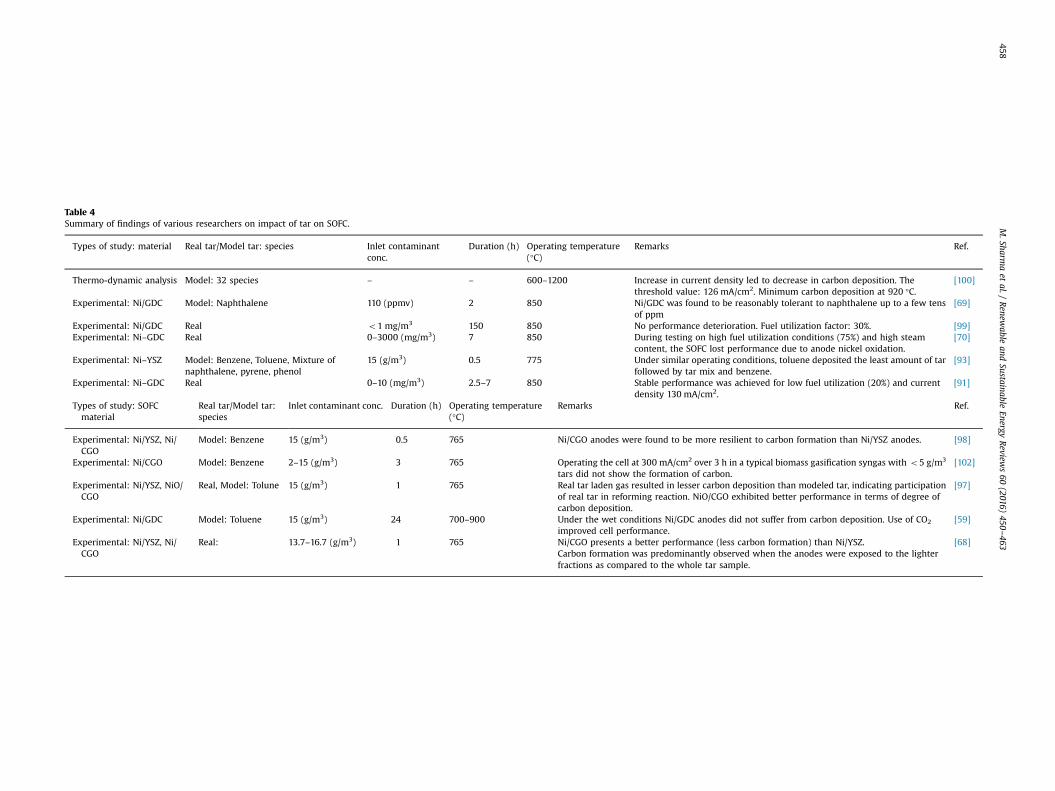
Table 4Summary of findings of various researchers on impact of tar on SOFC.
Types of study: material Real tar/Model tar: species Inlet contaminantconc.
Duration (h) Operating temperature(°C)
Remarks Ref.
Thermo-dynamic analysis Model: 32 species – – 600–1200 Increase in current density led to decrease in carbon deposition. Thethreshold value: 126 mA/cm2. Minimum carbon deposition at 920 °C.
[100]
Experimental: Ni/GDC Model: Naphthalene 110 (ppmv) 2 850 Ni/GDC was found to be reasonably tolerant to naphthalene up to a few tensof ppm
[69]
Experimental: Ni/GDC Real o1 mg/m3 150 850 No performance deterioration. Fuel utilization factor: 30%. [99]Experimental: Ni–GDC Real 0–3000 (mg/m3) 7 850 During testing on high fuel utilization conditions (75%) and high steam
content, the SOFC lost performance due to anode nickel oxidation.[70]
Experimental: Ni–YSZ Model: Benzene, Toluene, Mixture ofnaphthalene, pyrene, phenol
15 (g/m3) 0.5 775 Under similar operating conditions, toluene deposited the least amount of tarfollowed by tar mix and benzene.
[93]
Experimental: Ni–GDC Real 0–10 (mg/m3) 2.5–7 850 Stable performance was achieved for low fuel utilization (20%) and currentdensity 130 mA/cm2.
[91]
Types of study: SOFCmaterial
Real tar/Model tar:species
Inlet contaminant conc. Duration (h) Operating temperature(°C)
Remarks Ref.
Experimental: Ni/YSZ, Ni/CGO
Model: Benzene 15 (g/m3) 0.5 765 Ni/CGO anodes were found to be more resilient to carbon formation than Ni/YSZ anodes. [98]
Experimental: Ni/CGO Model: Benzene 2–15 (g/m3) 3 765 Operating the cell at 300 mA/cm2 over 3 h in a typical biomass gasification syngas with o5 g/m3
tars did not show the formation of carbon.[102]
Experimental: Ni/YSZ, NiO/CGO
Real, Model: Tolune 15 (g/m3) 1 765 Real tar laden gas resulted in lesser carbon deposition than modeled tar, indicating participationof real tar in reforming reaction. NiO/CGO exhibited better performance in terms of degree ofcarbon deposition.
[97]
Experimental: Ni/GDC Model: Toluene 15 (g/m3) 24 700–900 Under the wet conditions Ni/GDC anodes did not suffer from carbon deposition. Use of CO2
improved cell performance.[59]
Experimental: Ni/YSZ, Ni/CGO
Real: 13.7–16.7 (g/m3) 1 765 Ni/CGO presents a better performance (less carbon formation) than Ni/YSZ. [68]Carbon formation was predominantly observed when the anodes were exposed to the lighterfractions as compared to the whole tar sample.
M.Sharm
aet
al./Renew
ableand
SustainableEnergy
Review
s60
(2016)450
–463458
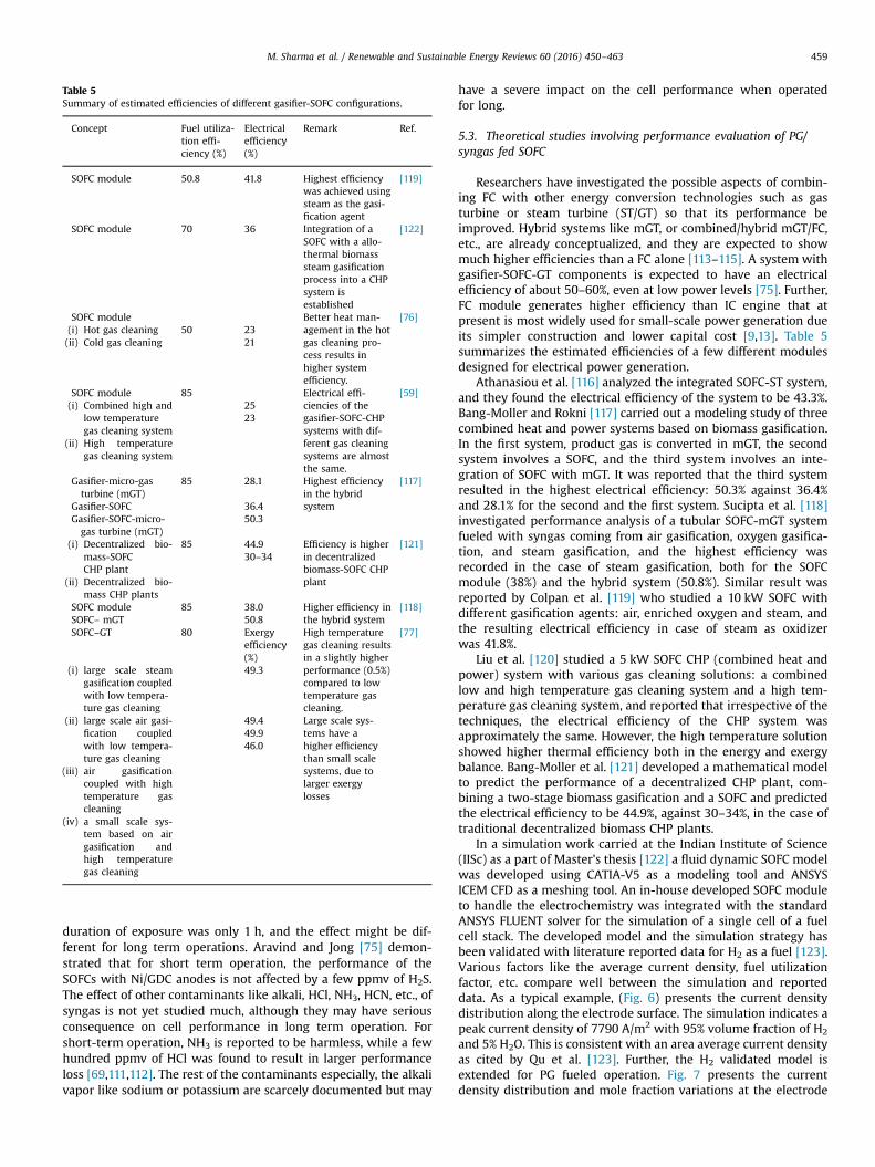
Table 5Summary of estimated efficiencies of different gasifier-SOFC configurations.
Concept Fuel utiliza-tion effi-ciency (%)
Electricalefficiency(%)
Remark Ref.
SOFC module 50.8 41.8 Highest efficiencywas achieved usingsteam as the gasi-fication agent
[119]
SOFC module 70 36 Integration of aSOFC with a allo-thermal biomasssteam gasificationprocess into a CHPsystem isestablished
[122]
SOFC module Better heat man-agement in the hotgas cleaning pro-cess results inhigher systemefficiency.
[76](i) Hot gas cleaning(ii) Cold gas cleaning
50 2321
SOFC module 85 Electrical effi-ciencies of thegasifier-SOFC-CHPsystems with dif-ferent gas cleaningsystems are almostthe same.
[59](i) Combined high and
low temperaturegas cleaning system
(ii) High temperaturegas cleaning system
2523
Gasifier-micro-gasturbine (mGT)
85 28.1 Highest efficiencyin the hybridsystem
[117]
Gasifier-SOFC 36.4Gasifier-SOFC-micro-gas turbine (mGT)
50.3
(i) Decentralized bio-mass-SOFCCHP plant
(ii) Decentralized bio-mass CHP plants
85 44.9 Efficiency is higherin decentralizedbiomass-SOFC CHPplant
[121]30–34
SOFC module 85 38.0 Higher efficiency inthe hybrid system
[118]SOFC– mGT 50.8SOFC–GT 80 Exergy
efficiency(%)
High temperaturegas cleaning resultsin a slightly higherperformance (0.5%)compared to lowtemperature gascleaning.
[77]
(i) large scale steamgasification coupledwith low tempera-ture gas cleaning
(ii) large scale air gasi-fication coupledwith low tempera-ture gas cleaning
(iii) air gasificationcoupled with hightemperature gascleaning
(iv) a small scale sys-tem based on airgasification andhigh temperaturegas cleaning
49.3
49.4 Large scale sys-tems have ahigher efficiencythan small scalesystems, due tolarger exergylosses
49.946.0
M. Sharma et al. / Renewable and Sustainable Energy Reviews 60 (2016) 450–463 459
duration of exposure was only 1 h, and the effect might be dif-ferent for long term operations. Aravind and Jong [75] demon-strated that for short term operation, the performance of theSOFCs with Ni/GDC anodes is not affected by a few ppmv of H2S.The effect of other contaminants like alkali, HCl, NH3, HCN, etc., ofsyngas is not yet studied much, although they may have seriousconsequence on cell performance in long term operation. Forshort-term operation, NH3 is reported to be harmless, while a fewhundred ppmv of HCl was found to result in larger performanceloss [69,111,112]. The rest of the contaminants especially, the alkalivapor like sodium or potassium are scarcely documented but may
have a severe impact on the cell performance when operatedfor long.
5.3. Theoretical studies involving performance evaluation of PG/syngas fed SOFC
Researchers have investigated the possible aspects of combin-ing FC with other energy conversion technologies such as gasturbine or steam turbine (ST/GT) so that its performance beimproved. Hybrid systems like mGT, or combined/hybrid mGT/FC,etc., are already conceptualized, and they are expected to showmuch higher efficiencies than a FC alone [113–115]. A system withgasifier-SOFC-GT components is expected to have an electricalefficiency of about 50–60%, even at low power levels [75]. Further,FC module generates higher efficiency than IC engine that atpresent is most widely used for small-scale power generation dueits simpler construction and lower capital cost [9,13]. Table 5summarizes the estimated efficiencies of a few different modulesdesigned for electrical power generation.
Athanasiou et al. [116] analyzed the integrated SOFC-ST system,and they found the electrical efficiency of the system to be 43.3%.Bang-Moller and Rokni [117] carried out a modeling study of threecombined heat and power systems based on biomass gasification.In the first system, product gas is converted in mGT, the secondsystem involves a SOFC, and the third system involves an inte-gration of SOFC with mGT. It was reported that the third systemresulted in the highest electrical efficiency: 50.3% against 36.4%and 28.1% for the second and the first system. Sucipta et al. [118]investigated performance analysis of a tubular SOFC-mGT systemfueled with syngas coming from air gasification, oxygen gasifica-tion, and steam gasification, and the highest efficiency wasrecorded in the case of steam gasification, both for the SOFCmodule (38%) and the hybrid system (50.8%). Similar result wasreported by Colpan et al. [119] who studied a 10 kW SOFC withdifferent gasification agents: air, enriched oxygen and steam, andthe resulting electrical efficiency in case of steam as oxidizerwas 41.8%.
Liu et al. [120] studied a 5 kW SOFC CHP (combined heat andpower) system with various gas cleaning solutions: a combinedlow and high temperature gas cleaning system and a high tem-perature gas cleaning system, and reported that irrespective of thetechniques, the electrical efficiency of the CHP system wasapproximately the same. However, the high temperature solutionshowed higher thermal efficiency both in the energy and exergybalance. Bang-Moller et al. [121] developed a mathematical modelto predict the performance of a decentralized CHP plant, com-bining a two-stage biomass gasification and a SOFC and predictedthe electrical efficiency to be 44.9%, against 30–34%, in the case oftraditional decentralized biomass CHP plants.
In a simulation work carried at the Indian Institute of Science(IISc) as a part of Master's thesis [122] a fluid dynamic SOFC modelwas developed using CATIA-V5 as a modeling tool and ANSYSICEM CFD as a meshing tool. An in-house developed SOFC moduleto handle the electrochemistry was integrated with the standardANSYS FLUENT solver for the simulation of a single cell of a fuelcell stack. The developed model and the simulation strategy hasbeen validated with literature reported data for H2 as a fuel [123].Various factors like the average current density, fuel utilizationfactor, etc. compare well between the simulation and reporteddata. As a typical example, (Fig. 6) presents the current densitydistribution along the electrode surface. The simulation indicates apeak current density of 7790 A/m2 with 95% volume fraction of H2
and 5% H2O. This is consistent with an area average current densityas cited by Qu et al. [123]. Further, the H2 validated model isextended for PG fueled operation. Fig. 7 presents the currentdensity distribution and mole fraction variations at the electrode
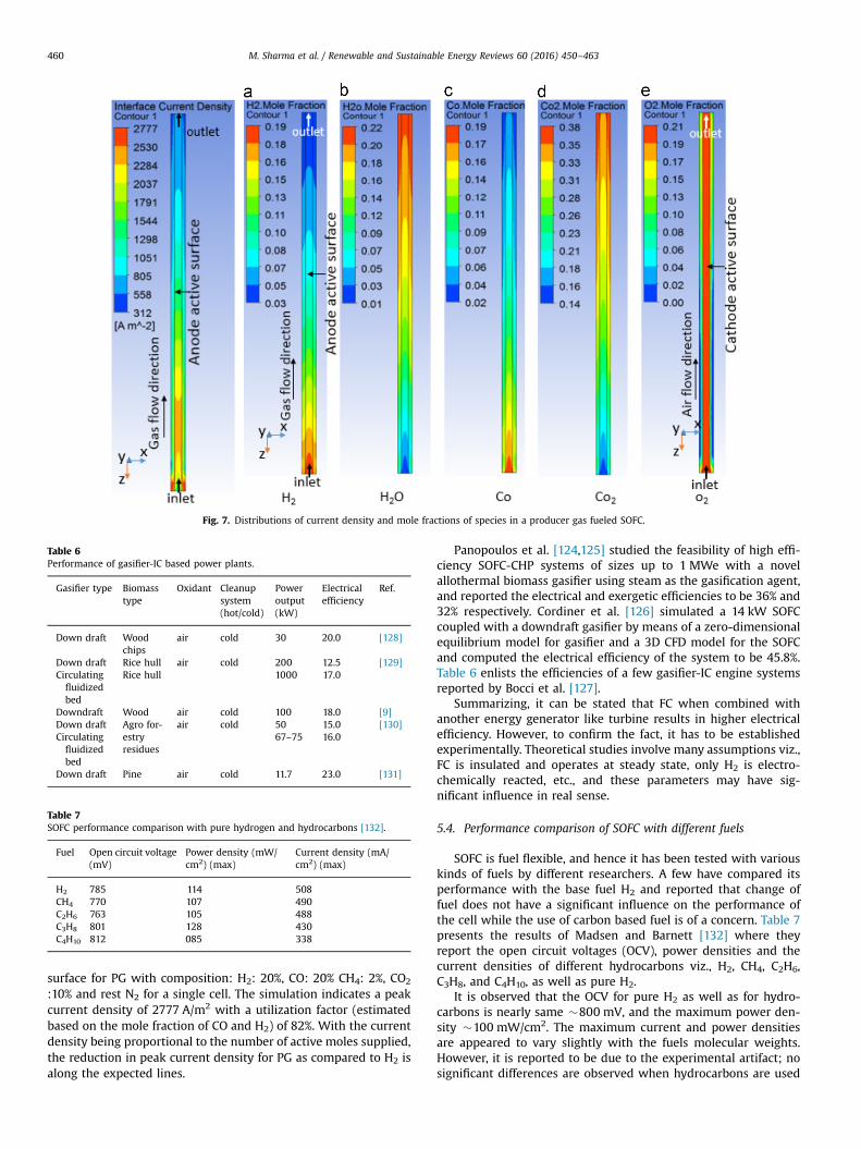
Fig. 7. Distributions of current density and mole fractions of species in a producer gas fueled SOFC.
Table 6Performance of gasifier-IC based power plants.
Gasifier type Biomasstype
Oxidant Cleanupsystem(hot/cold)
Poweroutput(kW)
Electricalefficiency
Ref.
Down draft Woodchips
air cold 30 20.0 [128]
Down draft Rice hull air cold 200 12.5 [129]Circulatingfluidizedbed
Rice hull 1000 17.0
Downdraft Wood air cold 100 18.0 [9]Down draft Agro for-
estryresidues
air cold 50 15.0 [130]Circulatingfluidizedbed
67–75 16.0
Down draft Pine air cold 11.7 23.0 [131]
Table 7SOFC performance comparison with pure hydrogen and hydrocarbons [132].
Fuel Open circuit voltage(mV)
Power density (mW/cm2) (max)
Current density (mA/cm2) (max)
H2 785 114 508CH4 770 107 490C2H6 763 105 488C3H8 801 128 430C4H10 812 085 338
M. Sharma et al. / Renewable and Sustainable Energy Reviews 60 (2016) 450–463460
surface for PG with composition: H2: 20%, CO: 20% CH4: 2%, CO2
:10% and rest N2 for a single cell. The simulation indicates a peakcurrent density of 2777 A/m2 with a utilization factor (estimatedbased on the mole fraction of CO and H2) of 82%. With the currentdensity being proportional to the number of active moles supplied,the reduction in peak current density for PG as compared to H2 isalong the expected lines.
Panopoulos et al. [124,125] studied the feasibility of high effi-ciency SOFC-CHP systems of sizes up to 1 MWe with a novelallothermal biomass gasifier using steam as the gasification agent,and reported the electrical and exergetic efficiencies to be 36% and32% respectively. Cordiner et al. [126] simulated a 14 kW SOFCcoupled with a downdraft gasifier by means of a zero-dimensionalequilibrium model for gasifier and a 3D CFD model for the SOFCand computed the electrical efficiency of the system to be 45.8%.Table 6 enlists the efficiencies of a few gasifier-IC engine systemsreported by Bocci et al. [127].
Summarizing, it can be stated that FC when combined withanother energy generator like turbine results in higher electricalefficiency. However, to confirm the fact, it has to be establishedexperimentally. Theoretical studies involve many assumptions viz.,FC is insulated and operates at steady state, only H2 is electro-chemically reacted, etc., and these parameters may have sig-nificant influence in real sense.
5.4. Performance comparison of SOFC with different fuels
SOFC is fuel flexible, and hence it has been tested with variouskinds of fuels by different researchers. A few have compared itsperformance with the base fuel H2 and reported that change offuel does not have a significant influence on the performance ofthe cell while the use of carbon based fuel is of a concern. Table 7presents the results of Madsen and Barnett [132] where theyreport the open circuit voltages (OCV), power densities and thecurrent densities of different hydrocarbons viz., H2, CH4, C2H6,C3H8, and C4H10, as well as pure H2.
It is observed that the OCV for pure H2 as well as for hydro-carbons is nearly same �800 mV, and the maximum power den-sity �100 mW/cm2. The maximum current and power densitiesare appeared to vary slightly with the fuels molecular weights.However, it is reported to be due to the experimental artifact; nosignificant differences are observed when hydrocarbons are used
Table 8SOFC performance comparison with pure and diluted hydrogen [133].
Fuel OCV (v) Power density(W/cm2) (max)
Limiting currentdensity (A/cm2)
H2 1.05 1.7 4.2H2–He (He concentration:15–78%)
0.9–1.0 0.75–1.5 1.5–4.0
H2–N2 (N2 concentration:15–80%)
0.9–1.0 0.5–1.5 0.9–3.7
H2–CO2 (CO2 concentration:15–81%)
0.85–0.95 0.4–1.3 0.6–3.5
H2–H2O (H2O concentra-tion: 15–80%)
0.85–.0.95 0.6–1.4 0.9–3.6
H2–CO (CO concentration:14–80%)
1.0 1.0–1.6 2.0–3.5
M. Sharma et al. / Renewable and Sustainable Energy Reviews 60 (2016) 450–463 461
in place of H2. However, considerable differences are observedwhen CO is used in place of H2. Jiang and Virkar [133] observed themaximum power density for CO as fuel: 0.7 w/m2 against 1.7 w/m2
for pure H2 in Ni–YSZ anode. Costa-Nunes et al. [42] observedsimilar performance with H2 and CO fuels in a cell with Cu–CeO2–
YSZ anodes. Slow diffusion and electrochemical reaction rates ofCO than H2 are the cause behind the lower maximum power andcurrent densities. Jiang and Virkar [133] however observed acomparable performance with pure H2 when CO was used incombination with H2, even when CO concentration was as high as55% due to additional H2 produced through water gas shift reac-tion Further, they reported about variation of electrochemicalparameters when pure H2 was replaced with diluted H2 (diluents:He, N2, CO2, H2O in varying concentrations �15–80%) due tohigher concentration polarization at higher concentration of thediluents (Table 8). Norheim [134] compared the performance ofSOFC with PG and natural gas and reported similar behavior (OCV:900 mv) for all the conditions tested.
In summary, the use of PG in place of H2 in FC shows a pro-mising approach as the electrochemical behavior of this fuel isfound similar. However, contamination of anode material is still amajor issue and needs a critical evaluation. There are argumentsrelated to the use of raw gas, but the degree of degradation of theelectrode is of serious concern compared to the trade of on effi-ciency improvement by a few percentage points. As indicatedearlier, the authors believe that it would be the desirable conditionto eliminate any contaminant before ingression of gas in the SOFCas there it would help to maintain the anode side clean withoutany fouling.
6. Conclusions
In summary, the coupling of biomass derived PG with high-temperature SOFC is an active area of research with clear efforts onthe development of newer material to support impurity laden fuelwithout noticeable cell degradation, and behavior of the con-taminants with the current existing materials. The progress madein the last few decades is noteworthy, however, the scope forcommercialization is still unclear, for durability of the technologyis challenged by few technical issues focusing on the appropriatematerial, gasification technology, cleaning of contaminants, etc.exists and need serious attention.
From the material perspective, challenges lie in developingchemically and thermally stable anode materials without beingindulged into carbon deposition and facilitating long term opera-tion. There is a need to carry out detailed investigations on thereaction mechanism and kinetics at each electrode, electrolyte,electrode/electrolyte interface and determine the degradationmechanism. Impacts of various contaminants on the existing Ni–
YSZ or Ni–GDC anode are to be largely explored while the chem-istry with newer probable material like Cu is to be well under-stood. The short term and long term effects of the trace con-taminants to be uncovered, and the tolerance limits of variouscontaminants are to be identified for fixing the requirement on thefuel side. It is observed that the current literature does not providea clear picture on the set limit for different contaminants, anddiscrepancies are believed to due to the differences in electrodematerial, microstructure differences and diverse operatingconditions.
In the modeling context, fluid and electrochemistry coupling isestablished and typical power density, overall efficiencies, etc. arepredicted with good accuracy. Thermodynamic studies are foundto provide some insights into carbon free operating conditionswhile experimental study rules out its reliability for carbondeposition as it was seen to occur above the thermodynamicallystable region, and this establishes the need for comprehensiveexperiments uncovering the chemistry. Correct of knowledge onthe behavior of the contaminants with SOFC components wouldhelp to specify the requirement of gas cleaning systems anddesigning the system with an economic viability, unlike the cur-rent hot gas cleanup technology. Utilizing the process heat, andacquiring better understanding on the interactions between thevarious species in PG and SOFC anodes would be the main criteriain lowering the cost and establish the durability of the technology.
References
[1] Lucia U. Overview on fuel cells. Renew Sustain Energy Rev 2014;30:164–9.[2] Singhal SC. Advances in solid oxide fuel cell technology. Solid State Ionics
2000;135:305–13.[3] Schlapbach L, Zuttel A. Hydrogen-storage materials for mobile applications.
Nature 2001;414:353–8.[4] Gong Y, Huang K. Study of a renewable biomass fueled SOFC: the effect of
catalysts. Int J Hydrog Energy 2013;38:16518–23.[5] Huang W-D, Zhang Y-HP. Energy efficiency analysis: biomass-to-wheel effi-
ciency related with biofuels production, fuel distribution, and powertrainsystems. PLoS One 2011;6(7) (Viewed on 25/12/2015)⟨http://www.plosone.org/article/fetchObject.action?uri¼ info:doi/10.1371/journal.pone.0022113&representation¼PDF⟩.
[6] Piriou B, Vaitilingom G, Veyssière B, Cuq B, Rouau X. Potential direct use ofsolid biomass in internal combustion engines. Prog Energy Combust Sci2013;39(1):169–88.
[7] Buragohain B, Mahanta P, Moholkar VJ. Biomass gasification for decen-tralized power generation: the Indian perspective. Renew Sustain Energy Rev2010;14:73–92.
[8] Dasappa S, Sridhar HV. Performance of a diesel engine in a dual fuel modeusing PG for electricity power generation. Int J Sustain Energy 2013;32(3):153–68.
[9] Dasappa S, Sridhar HV, Mazumdar I. Experiments on and thermodynamicanalysis of a turbocharged engine with PG as fuel. Proc Inst Mech Eng Part C:J Mech Eng Sci 2012;226:1004–15.
[10] Dasappa S, Subbukrishna DN, Suresh KC, Paul PJ, Prabhu GS. Operationalexperience on a grid connected 100 kWe biomass gasification power plant inKarnataka, India. Energy Sustain Dev 2011;15:231–9.
[11] Shivapuji AM, Dasappa S. Experiments and zero D modeling studies usingspecific Wiebe coefficients for PG as fuel in spark-ignited engines. Proc InstMech Eng Part C: J Mech Eng Sci 2012;227(3):504–19.
[12] Shivapuji AM, Dasappa S. Selection and thermodynamic analysis of a tur-bocharger for a PG-fuelled multi-cylinder engine. Proc Inst Mech Eng Part A:J Power Energy 2014;228(3):340–56.
[13] Sridhar HV, Sridhar G, Dasappa S, Paul PJ, Mukunda HS. On the operation of ahigh pressure biomass gasifier with gas turbine. In: Proceedings of the 15thEuropean biomass conference & exhibition; 2007. p. 964–67.
[14] Stambouli AB. Fuel cells: the expectations for an environmental-friendly andsustainable source of energy. Renew Sustain Energy Rev 2011;15:4507–20.
[15] Stambouli AB, Traversa E. Solid oxide fuel cells (SOFCs): a review of anenvironmentally clean and efficient source of energy. Renew Sustain EnergyRev 2002;6:433–55.
[16] Laosiripojana N, Wiyaratn W, Kiatkittipong W, Arpornwichanop A, Sootti-tantawat A, Assabumrungrat S. Reviews on solid oxide fuel cell technology.Eng J 2009;13(1):65–83.
[17] Adams TA, Nease J, Tucker D, Barton PI. Energy conversion with solid oxidefuel cell systems: a review of concepts and outlooks for the short and longterm. Ind Eng Chem Res 2013;52:3089–111.
M. Sharma et al. / Renewable and Sustainable Energy Reviews 60 (2016) 450–463462
[18] Zuo C, Liu M, Liu M. Solid oxide fuel cells. In: Aparicio M, Jitianu A, Klein LC,editors. Sol–gel processing for conventional and alternative energy, advancesin sol–gel derived materials and technology. New York: Springer; 2012.p. 7–36.
[19] Sammes N, editor. Fuel cell technology: reaching towards commercialization.Manchester: Springer; 2006.
[20] Minh NQ. Solid oxide fuel cell technology-features and applications. SolidState Ionics 2004;174:271–7.
[21] Fergus JW, Hui R, Li X, Wilkinson DP, Zhang J, editors. Solid oxide fuel cells:materials properties and performance. Boca Raton: CRC Press; 2009.
[22] Nesaraj AS. Recent developments in solid oxide fuel cell – a review. J Sci IndRes 2010;69:169–76.
[23] Yokokawa H. Overview of intermediate-temperature solid oxide fuel cells.In: Ishihara T, editor. Perovskite oxide for solid oxide fuel cells, Fuel cells andhydrogen energy; 2009. p. 17–43.
[24] Badwal SPS. Stability of solid oxide fuel cell components. Solid State Ionics2001;143:39–46.
[25] Charpentier P, Fragnaud P, Schleich DM, Gehain E. Preparation of thin filmSOFCs working at reduced temperature. Solid State Ionics 2000;135:373–80.
[26] Wincewicz KC, Cooper JS. Taxonomies of SOFC material and manufacturingalternatives. J Power Sources 2005;140(2):280–96.
[27] Zhao Y, Xia C, Jia L, Wang Z, Li H, Yu J, et al. Recent progress on solid oxidefuel cell: lowering temperature and utilizing non-hydrogen fuels. Int JHydrog Energy 2013;38:16498–517.
[28] Taroco HA, Santos JAF, Domingues RZ, Matencio T. Ceramic materials forsolid oxide fuel cells. In: Sikalidis C, editor. Advances in ceramics – synthesisand characterization, processing and specific applications. Rijeka: InTech;2011. p. 423–46.
[29] Jacobson AJ. Materials for solid oxide fuel cells. Chem Mater 2010;22:660–74.[30] Fergus JW. Materials challenges for solid-oxide fuel cells. JOM 2007;59:56–
62.[31] Chunwen S, Hui R, Roller J. Cathode materials for solid oxide fuel cells: a
review. J. Solid State Electrochem 2010;14:1125–44.[32] Zhu WZ, Deevi SC. A review on the status of anode materials for solid oxide
fuel cells. Mater Sci Eng A 2003;362:228–39.[33] Mahato N, Banerjee A, Gupta A, Omar S, Balani K. Progress in material selec-
tion for solid oxide fuel cell technology. Prog Mater Sci 2015;72:141–337.[34] Minh NQ, Takahashi T. Science and technology of ceramic fuel cells.
Amsterdam: Elsevier; 1995.[35] Belardi RM, Deseure J, Brant MC, Matencio T, Domingues RZ. Electrical study
of cathodic activation and relaxation of La0,80Sr0,20MnO3. Ionics 2009;15(2):227–32.
[36] Brant MC, Matencio T, Dessemond L, Domingues RZ. Electrical and micro-structural aging of porous lanthanum strontium manganite/yttria-dopedcubic zirconia electrodes. Chem Mater 2001;13(11):3954–61.
[37] Sun C, Hui R, Roller J. Cathode materials for solid oxide fuel cells: a review. JSolid State Electrochem 2010;14:1125–44.
[38] Shri Prakash B, Kumar SS, Aruna ST. Properties and development of Ni/YSZ asan anode material in solid oxide fuel cell: a review. Renew Sustain EnergyRev 2014;36:149–79.
[39] Mermelstein J, Millan M, Brandon NP. The impact of carbon formation on Ni–YSZ anodes from biomass gasification model tars operating in dry condi-tions. Chem Eng Sci 2009;64:492–500.
[40] Restivo TAG, Mello-Castanho SRH. Cu–Ni–YSZ anodes for solid oxide fuel cellby mechanical alloying processing. Int J Mater Res 2010;101:128–32.
[41] Cheng K, Chen H, Weng W, Song C, Du P, Shen G, et al. Effects of dual Cuincorporation on carbon deposition in SDC anode. J Alloy Compd2012;541:65–9.
[42] Costa-Nunes O, Gorte RJ, Vohs JM. Comparison of the performance of Cu–CeO2–YSZ and Ni–YSZ composite SOFC anodes with H2, CO and syngas. JPower Sources 2005;141:241–9.
[43] Ye XF, Wang SR, Zhou J, Zeng FR, Nie HW, Wen TL. Application of a Cu–CeO2/Ni–yttria-stabilized zirconia multi-layer anode for anode-supported Solidoxide fuel cells operating on H2–CO syngas fuels. J Power Sources2011;196:5499–502.
[44] Fergus JW. Sealants for solid oxide fuel cells. J Power Sources 2005;147:46–57.[45] Mahapatra MK, Lu K. Glass-based seals for solid oxide fuel and electrolyzer
cells – a review. Mater Sci Eng R 2010;67:65–85.[46] Pereira EG, da Silva JN, de Oliveira JL, Machado CS. Sustainable energy: a
review of gasification technologies. Sustain Energy Rev 2012;16:4753–62.[47] Gunarathne D. Optimization of the performance of down-draft biomass
gasifier installed at National Engineering Research & Development (NERD)(Masters thesis). Sweden: KTH; 2012.
[48] Sandeep K, Dasappa S. Oxy–steam gasification of biomass for hydrogen richsyngas production using downdraft reactor configuration. Int J Energy Res2014;38:174–88.
[49] Anis S, Zainal ZA. Tar reduction in biomass PG via mechanical, catalytic andthermal methods: a review. Renew Sustain Energy Rev 2011;15:2355–77.
[50] Asadullah M. Barriers of commercial power generation using biomass gasi-fication gas: a review. Renew Sustain Energy Rev 2014;29:201–15.
[51] Salam PA, Kumar SS, Siriwardhana M. The status of biomass gasification inThailand and Cambodia. Report prepared for the Energy Environment Part-nership (EEP), Mekong Region. Bangkok, Thailand: Asian Institute of Tech-nology; 2010.
[52] Warnecke R. Gasification of biomass: comparison of fixed bed and fluidizedbed gasifier. Biomass Bioenergy 2000;18:489–97.
[53] Siedlecki M, de Jong W, Verkooijen AHM. Fluidized bed gasification as amature and reliable technology for the production of bio-syngas and appliedin the production of liquid transportation fuels: a review. Energies2011;4:389–434.
[54] Ruiz JA, Jua´rez MC, Morales MP, Mun~oz P, Mendı´vi MA. Biomass gasifi-cation for electricity generation: review of current technology barriers.Renew Sustain Energy Rev 2013;18:174–83.
[55] Kohli S, Ravi MR. Biomass gasification for rural electrification: prospects andchallenges. SESI J 2003;13:83–101.
[56] Guangul FM, Sulaiman SA, Ramli A. Gasifier selection, design and gasificationof oil palm fronds with preheated and unheated gasifying air. BioresourTechnol 2012;126:224–32.
[57] Kirkles AF, Verbong GPJ. Biomass gasification: still promising? A 30-yearglobal overview Renew Sustain Energy Rev 2011;15:471–81.
[58] Nagel FP, Ghosh S, Pitta C, Schildhauer TJ, Biollaz S. Biomass integratedgasification fuel cell systems concept development and experimental results.Biomass Bioenergy 2011;35:354–62.
[59] Liu M, van der Kleij A, Verkooijen AHM, Aravind PV. An experimental studyof the interaction between tar and SOFCs with Ni/GDC anodes. Appl Energy2013;108:149–57.
[60] Liu M, Millan MG, Aravind PV, Brandon N. Influence of operating conditionson carbon deposition in SOFCs fuelled by tar-containing biosyngas. J Elec-trochem Soc 2011;158:B1310–8.
[61] Basu P. Biomass gasification and pyrolysis: practical design and theory.Oxford: Elsevier; 2010.
[62] Heidenreich S, Foscolo PU. New concepts in biomass gasification. ProgEnergy Combust Sci 2015;46:72–95.
[63] Hasler P, Nussbaumer T. Gas cleaning for IC engine applications from fixedbed biomass gasification. Biomass Bioenergy 1999;16:385–95.
[64] Devi L, Ptasinski KJ, Janssen FJJG. A review of the primary measures for tarelimination in biomass gasification processes. Biomass Bioenergy2003;24:125–40.
[65] Rabou LPLM, Zwart RWR, Vreudgenhil BRJ, Bos L. Tar in Biomass PG, theenergy research centre of The Netherlands (ECN) Experience: an enduringchallenge. Energy Fuels 2009;23:6189–98.
[66] Richardson Y, Blin J, Julbe A. A short overview on purification and conditioningof syngas produced by biomass gasification: catalytic strategies, processintensification and new concepts. Prog Energy Combust Sci 2012;38:765–81.
[67] Woolcock PJ, Brown RC. A review of cleaning technologies for biomass-derived syngas. Biomass Bioenergy 2013;52:54–84.
[68] Lorente E, Berrueco C, Millan M, Brandon NP. Effect of tar fractions from coalgasification on nickel yttria stabilized zirconia and nickel gadolinium dopedceria solid oxide fuel cell. J Power Sources 2013;242:824–31.
[69] Aravind PV, Ouweltjes JP, Woudstra N, Rietveld G. Impact of biomass derivedcontaminants on SOFCs with Ni/Gadolinia-doped ceria anodes. ElectrochemSolid State Lett 2008;11(2):B24–8.
[70] Hofmann P, Panopoulos KD, Fryda LE, Schweiger A, Ouweltjes JP, Karl J.Integrating biomass gasification with solid oxide fuel cells: effect of realproduct gas tars, fluctuations and particulates on Ni–GDC anode. Int J HydrogEnergy 2008;33:2834–44.
[71] Asadullah M. Biomass gasification gas cleaning for downstream applications:a comparative critical review. Renew Sustain Energy Rev 2014;40:118–32.
[72] Mondal P, Dang GS, Garg MO. Syngas production through gasification andcleanup for downstream applications – recent developments. Fuel ProcessTechnol 2011;92:1395–410.
[73] Singh R, Shukla A. A review on methods of flue gas cleaning from combus-tion of biomass. Renew Sustain Energy Rev 2014;29:854–64.
[74] Prabhansu, Karmakar MK, Chandra P, Chatterjee PK. A review on the fuel gascleaning technologies in gasification process. J Environ Chem Eng2015;3:689–702. http://dx.doi.org/10.1016/j.jece.2015.02.011.
[75] Aravind PV, de Jong W. Evaluation of high temperature gas cleaning optionsfor biomass gasification product gas for solid oxide fuel cells. Prog EnergyCombust Sci 2012;38:737–64.
[76] Omosun AO, Bauen A, Brandon NP, Adjiman CS, Hart D. Modelling systemefficiencies and costs of two biomass-fuelled SOFC systems. J Power Sources2004;131:96–106.
[77] Toonssen R, Sollai S, Aravind PV, Woudstra N, Verkooijen AHM. Alternativesystem designs of biomass gasification SOFC/GT hybrid systems. Int J HydrogEnergy 2011;36:10414–25.
[78] Jaojaruek K, Jarungthammachote S, Gratuito MKB, Wongsuwan H, Homhuwal S.Experimental study of wood downdraft gasification for an improved PG qualitythrough an innovative two-stage air and premixed air/gas supply approach.Bioresour Technol 2011;102:4834–40.
[79] Bhattacharya SC, Siddique AHMMR, Pham HL. A study on wood gasificationfor low-tar gas production. Energy 1999;24:285–96.
[80] cgpl.iisc.ernet.in (viewed on 29/01/2015).[81] Dasappa S, Mukunda HS, Paul PJ, Rajan NKS. Biomass to energy – the science
and technology of the IISc bio-energy Systems. Bangalore: ABETS; 2003.[82] Dasappa S, Shrinivasa U, Baliga BN, Mukunda HS. Five-kilowatt wood gasifier
technology: evolution and field experience. Sadhana 1989;14(3):187–212.[83] Mahapatra S, Dasappa S. Experiments and analysis of propagation front
under gasification regimes in a packed bed. Fuel Process Technol2014;121:83–90.
[84] Mahapatra S, Dasappa S. Influence of surface area to volume ratio of fuelparticles on gasification process in a fixed bed. Energy Sustain Dev2014;19:122–9.
M. Sharma et al. / Renewable and Sustainable Energy Reviews 60 (2016) 450–463 463
[85] Sridhar G, Dasappa S, Sridhar HV, Paul PJ, Rajan NKS, Prakasam Kummar VS, et al.Green electricity – a case study of a grid linked independent power. In: Proceedingsof the 15th European biomass conference and exhibition; 7–11 May 2007.
[86] Dasappa S. Potential of biomass energy for electricity generation in sub-Saharan Africa. Energy Sustain Dev 2011;15(3):203–13.
[87] Ayagh HG, Jolly S, Patel D, Stauffer D. Solid oxide fuel cell system utilizingsyngas from coal gasifiers. Ind Eng Chem Res 2013;52:3112–20.
[88] Fan L, Dimitriou E, Pourquie MJBM, Liu M, Verkooijen AHM, Aravind PV.Prediction of the performance of a solid oxide fuel cell fuelled with bio-syngas: influence of different steam-reforming reaction kinetic parameters.Int J Hydrog Energy 2013;38:510–24.
[89] Colpan CO, Dincer I, Hamdullahpur F. The reduction of greenhouse gasemissions using various thermal systems in a landfill site. Int J Glob Warm2009;1:89–105.
[90] Doherty W, Reynolds A, Kennedy D. Computer simulation of a biomassgasification-solid oxide fuel cell power system using Aspen Plus. Energy2010;35:4545–55.
[91] Hofmann P, Panopoulos KD, Aravind PV, Siedlecki M, Schweiger A, Karl J,et al. Operation of solid oxide fuel cell on biomass product gas with tarlevels 410 g N m�3. Int J Hydrog Energy 2009;34:9203–12.
[92] Campitelli G, Cordiner S, Gautam M, Mariani A, Mulone V. Biomass fueling ofa SOFC by integrated gasifier: study of the effect of operating conditions onsystem performance. Int J Hydrog Energy 2013;38:320–7.
[93] Mermelstein J, Brandon N, Millan M. Impact of Steam on the Interactionbetween biomass gasification tars and nickel-based solid oxide fuel cellanode materials. Energy Fuels 2009;23:5042–8.
[94] Wongchanapai S, Iwai H, Saito M, Yoshida H. Performance evaluation of anintegrated small-scale SOFC-biomass gasification power generation system. JPower Sources 2012;216:314–22.
[95] Colpan CO, Fung AS, Hamdullahpur F. Modeling of an integrated two-stagebiomass gasifier and solid oxide fuel cell system. Biomass Bioenergy2012;42:132–42.
[96] Zhu B, Bai XY, Chen GX, Yi WM, Bursell M. Fundamental study on biomass-fuelled ceramic fuel cell. Int J Energy Res 2002;26:57–66.
[97] Lorente E, Millan M, Brandon NP. Use of gasification syngas in SOFC: impactof real tar on anode materials. Int J Hydrog Energy 2012;37:7271–8.
[98] Mermelstein J, Millan M, Brandon N. The impact of steam and currentdensity on carbon formation from biomass gasification tar on Ni/YSZ, and Ni/CGO solid oxide fuel cell anodes. J Power Sources 2010;195:1657–66.
[99] Hofmann P, Schweiger A, Fryda, L, Panopoulos KD, Hohenwarter U, BentzenJD, et al. High temperature electrolyte supported Ni–GDC/YSZ/LSM SOFCoperation on two-stage Viking gasifier product gas. J Power Sources2007;173:357–66.
[100] Singh D, Hern´andez-Pacheco E, Hutton PN, Patel N, Mann MD. Carbondeposition in an SOFC fueled by tar-laden biomass gas: a thermodynamicanalysis. J Power Sources 2005;142:194–9.
[101] Aravind PV, Ouweltjes JP, Woudstra N, Rietveld G. Impact of biomass-derivedcontaminants on SOFCs with Ni/Gadolinia-doped ceria anodes. ElectrochemSolid-State Lett 2008;11(2):B24–8.
[102] Mermelstein J, Millan M, Brandon NP. The interaction of biomass gasificationsyngas components with tar in a solid oxide fuel cell and operational con-ditions to mitigate carbon deposition on nickel–gadolinium doped ceriaanodes. J Power Sources 2011;196:5027–34.
[103] Biollaz SMA, Hottinger P, Pitta C, Karl J. Results from a 1200 h test of a tubularSOFC with wood gas. In: Proceedings of the 17th European biomass con-ference & exhibition. Florence Hamburg: ETA; 2009. p. 635–638.
[104] Martini S, Kleinhappl M, Hofbauer H. High temperature gas treatment for theoperation of a solid oxide fuel cell (SOFC). In: Proceedings of the 17th Eur-opean biomass conference & exhibition. Florence Hamburg (Germany): ETA;2009. p. 652–660.
[105] Dekker NJJ and Rietveld G. Highly efficient conversion of ammonia intoelectricity by solid oxide fuel cells. In: Mogensen M, editor. Proceedings ofthe Sixth European solid oxide fuel cell forum. Oberrohrdorf (Switzerland);2004.
[106] Pieratti E, Baratieri M, Ceschini S, Tognana L, Baggio P. Syngas suitability forsolid oxide fuel cells applications produced via biomass steam gasificationprocess: experimental and modeling analysis. J Power Sources2011;196:10038–49.
[107] Lohsoontorn P, Brett DJL, Brandon NP. The effect of fuel composition andtemperature on the interaction of H2S with nickel–ceria anodes for solidoxide fuel cells. J Power Sources 2008;183:232–9.
[108] Veyo SE. Evaluation of fuel impurity effects on solid oxide fuel cell perfor-mance (Final technical report). Pittsburgh: Westinghouse Electric Company;1998.
[109] Matsuzaki Y, Yasuda I. The poisoning effect of sulfur-containing impurity gason a SOFC anode: Part I. Dependence on temperature, time, and impurityconcentration. Solid State Ionics 2000;132:261–9.
[110] Norheim A, Wærnhus I, Brostrom M, Hustad JE, Vik A. Experimental Studieson the Influence of H2S on solid oxide fuel cell performance at 800 °C. EnergyFuels 2007;21:1098–101.
[111] Trembly JP, Gemmen RS, Bayless DJ. The effect of coal syngas containing AsH3
on the performance of SOFCs: investigations into the effect of operationaltemperature, current density and AsH3 concentration. J Power Sources2007;171:818–25.
[112] Xu C, Gong M, Zondlo JW, Liu XB, Finklea HO. The effect of HCl in syngas onNi–YSZ anode-supported solid oxide fuel cells. J Power Sources2010;195:2149–58.
[113] Zhang X, Chan SH, Li G, Ho HK, Li J, Feng Z. A review of integration strategiesfor solid oxide fuel cells. J Power Sources 2010;195:685–702.
[114] Sadhukhan J, Zhao Y, Shah N, Brandon NP. Performance analysis of integratedbiomass gasification fuel cell (BGFC) and biomass gasification combined cycle(BGCC) systems. Chem Eng Sci 2010;65(6):1942–54.
[115] Karellas S, Karl J, Kakaras E. An innovative biomass gasification process and itscoupling with microturbine and fuel cell systems. Energy 2008;33:284–91.
[116] Athanasiou C, Coutelieris F, Vakouftsi E, Skoulou V, Antonakou E, Marnellos G,et al. From biomass to electricity through integrated gasification/SOFC system-optimization and energy balance. Int J Hydrog Energy 2007;32:337–42.
[117] Bang-Møller C, Rokni M. Thermodynamic performance study of biomassgasification, solid oxide fuel cell and micro gas turbine hybrid systems.Energy Convers Manag 2010;51:2330–9.
[118] Sucipta M, Kimijima S, Suzuki K. Performance analysis of the SOFC-MGThybrid system with gasified biomass fuel. J Power Sources 2007;174:124–35.
[119] Colpan CO, Hamdullahpur F, Dincer I, Yoo Y. Effect of gasification agent on theperformance of solid oxide fuel cell and biomass gasification systems. Int JHydrog Energy 2010;35(10):5001–9.
[120] Liu M, Aravind PV, Woudstra T, Cobas VRM, Verkooijen AHM. Developmentof an integrated gasifier–solid oxide fuel cell test system: a detailed systemstudy. J Power Sources 2011:7277–89.
[121] Bang-Møller C, Rokni M, Elmegaard B, Ahrenfeldt J, Henriksen UB. Decen-tralized combined heat and power production by two-stage biomass gasifi-cation and solid oxide fuel cells. Energy 2013:527–37.
[122] Manikanta. Numerical investigation of solid oxide fuel cell for syn-gas appli-cation (Masters thesis). Belagavi: Visvesvaraya Technological University Bela-gavi; 2015.
[123] Qu Z, Aravind PV, Boksteen SZ, Dekker NJJ, Janssen HH, Woudstra N, et al.Three-dimensional computational fluid dynamics modeling of anode-supported planar SOFC. Int J Hydrog Energy 2011;36(16):10209–20.
[124] Panopoulos KD, Fryda LE, Karl J, Poulou S, Kakaras E. High temperature solidoxide fuel cell integrated with novel allothermal biomass gasification Part I:modelling and feasibility study. J Power Sources 2006;159:570–85.
[125] Panopoulos KD, Fryda L, Karl J, Poulou S, Kakaras E. High temperature solidoxide fuel cell integrated with novel allothermal biomass gasification Part II:exergy analysis. J Power Sources 2006;159:586–94.
[126] Cordiner S, Feola M, Mulone V, Romanelli F. Analysis of a SOFC energy gen-eration system fuelled with biomass reformate. Appl Therm Eng 2007;27:738–47.
[127] Bocci E, Sisinni M, Moneti M, Vecchione L, DiCarlo A, Villarini M. State of artof small scale biomass gasification power systems: a review of the differenttypologies. Energy Procedia 2014;45:247–56.
[128] Warren TJB, Poulter R, Parfitt RI. Converting biomass to electricity on a farm-sized scale using downdraft gasification and a spark-ignition engine. Bior-esour Technol 1995;52:95–8.
[129] Wu C, Huang H, Zheng SP, Yin XL. An economic analysis of biomass gasifi-cation and power generation in China. Bioresour Technol 2002;83:65–70.
[130] Zhou Z, Yin X, Xu J, Ma L. The development situation of biomass gasificationpower generation in China. Energy Policy 2012;51:52–7.
[131] Lee U, Balu E, Chung JN. An experimental evaluation of an integrated biomassgasification and power generation system for distributed power applications.Appl Energy 2013;101:699–708.
[132] Madsen BD, Barnett SA. Effect of fuel composition on the performance ofceramic-based solid oxide fuel cell anodes. Solid State Ionics 2005;176:2545–53.
[133] Jiang Y, Virkar AV. Fuel composition and diluent effect on gas transport andperformance of anode-supported SOFCs. J Electrochem Soc 2003;150(7):A942–51.
[134] Norheim A. Experimental investigation of solid oxide fuel cells using biomassgasification PGes (Ph.D thesis). Norway: Norwegian University of Science andTechnology; 2005.