“renewable energy – connecting wind farms to the … kv 33 kv 125 mva 13% z 156 mw 39 mw -47...
TRANSCRIPT
John Diaz de Leon, P.E.
Consulting T&D Planning Engineer
““Renewable Energy Renewable Energy ––Connecting Wind Farms to the Grid”Connecting Wind Farms to the Grid”
IEEE PES – Milwaukee Chapter MeetingApril, 2008

2
Discussion TopicsDiscussion Topics
• Wind Farm Basics
• Grid Integration Issues
• Interconnection Standards
• Wind Farm Modeling
• Wind Farm Integration Analysis
• Integration of Wind into the Grid using Dynamic Reactive Compensation (D-VAR®)

3
Global Wind Generation: Capacity (YE 2006)Global Wind Generation: Capacity (YE 2006)
• Germany 20,622 MW 27.8%• Spain 11,615 MW 15.6%• USA 11,603 MW 15.6%• India 6,207 MW 8.4%• Denmark 3,136 MW 4.2%• China 2,604 MW 3.5%• Italy 2,123 MW 2.9%• UK 1,963 MW 2.6%• Rest of world 14,288 MW 19.2%
Global Total 74,223 MW

4
Global Wind Generation: New Capacity (YE 2006)Global Wind Generation: New Capacity (YE 2006)
• USA 2,454 MW 16.1%• Germany 2,233 MW 14.7%• India 1,840 MW 12.1%• Spain 1,587 MW 10.4%• China 1,347 MW 8.9%• France 810 MW 5.3%• Canada 776 MW 5.1%• Portugal 694 MW 4.6%• Rest of world 3,456 MW 22.7%
Global Total 15,197 MW

5
Capacity by Region (YE 2006)Capacity by Region (YE 2006)

6
Global Forecast 2006-2010Global Forecast 2006-2010
Cumulative Capacity Annual Growth

7
Global Wind Turbine Sales LeadersGlobal Wind Turbine Sales Leaders
2004 2005• Vestas• GE• Enercon• Gamesa• Suzlon
27%17%13%10%6%
32%12%16%10%3%
8
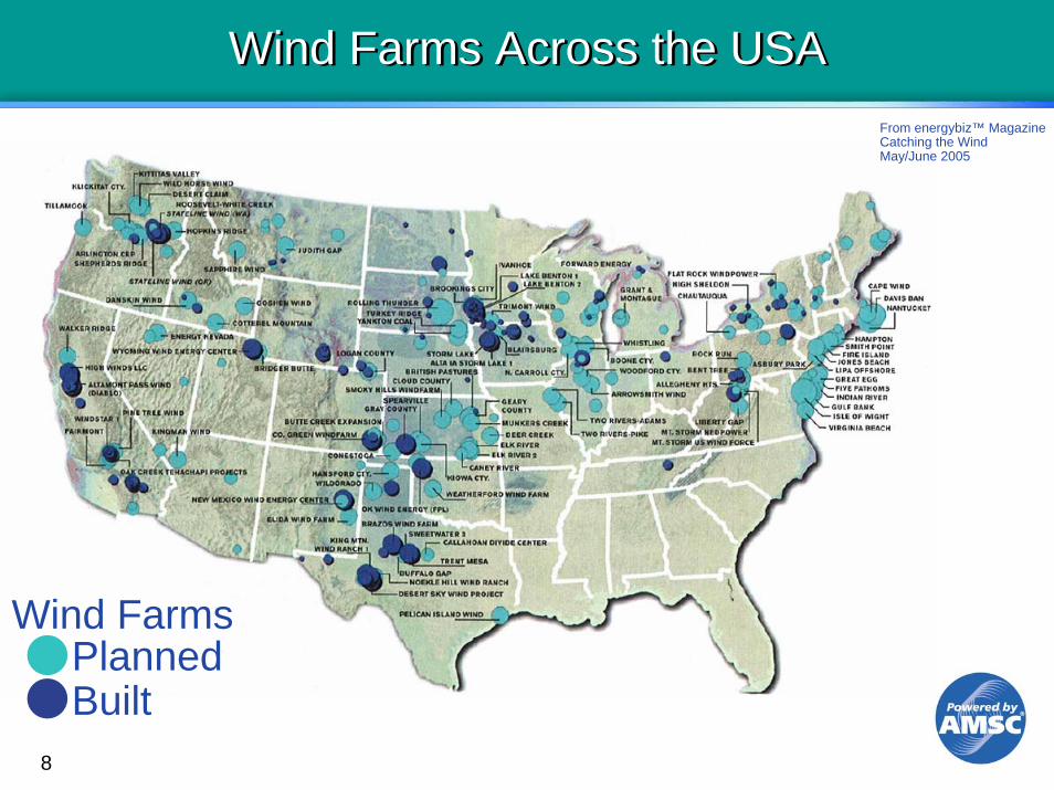
Wind Farms Across the USAWind Farms Across the USA
PlannedBuilt
Wind Farms
From energybiz™ MagazineCatching the WindMay/June 2005

9
USA Annual Average Wind PowerUSA Annual Average Wind Power

10
Wisconsin State Journal – 04/04/08Wisconsin State Journal – 04/04/08

11
Wind Generator SizesWind Generator Sizes

12
Typical Wind Turbine Typical Wind Turbine
Tower
Blades
Hub
Nacelle
60-80 Meters
13
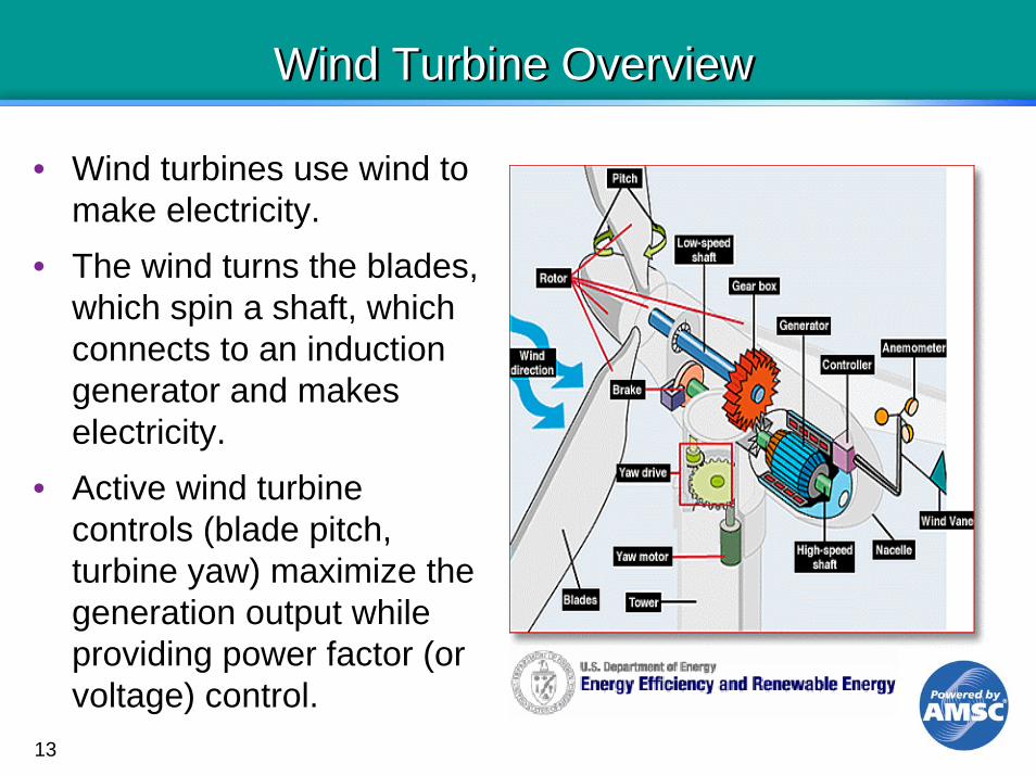
Wind Turbine OverviewWind Turbine Overview
• Wind turbines use wind to make electricity.
• The wind turns the blades, which spin a shaft, which connects to an induction generator and makes electricity.
• Active wind turbine controls (blade pitch, turbine yaw) maximize the generation output while providing power factor (or voltage) control.

14
Wind Plant OverviewWind Plant Overview
• The wind plant connects to the utility grid at the interconnection substation (typically 69-230 kV) which includes:- Breakers- Step-Up Transformer- Voltage/PF Control
Equipment• A network of underground
feeders (typically 34.5 kV) connect the wind turbines to the substation.
• Wind turbines integrate:- Generation Control- Voltage/PF Control
• Wind plants utilize automated (voltage/PF) control schemes
15
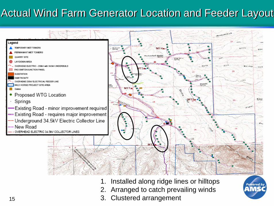
Actual Wind Farm Generator Location and Feeder LayoutActual Wind Farm Generator Location and Feeder Layout
1. Installed along ridge lines or hilltops2. Arranged to catch prevailing winds3. Clustered arrangement

16
Types of TurbinesTypes of Turbines
1. Direct Connected Asynchronous
generator
PlantFeeders
PF controlcapacitors
Characteristics• Induction generator connected direct to line• Fixed Speed @ 1-2% above synchronous• No power converter• No voltage control capability• Susceptible to voltage and frequency disturbances• Absorbs VARs while generating real power• PF correction is through LV capacitors in Nacelle• Typical of the older style generators• Examples: Mitsubishi, NEG Micon, Bonus
17
Types of TurbinesTypes of Turbines
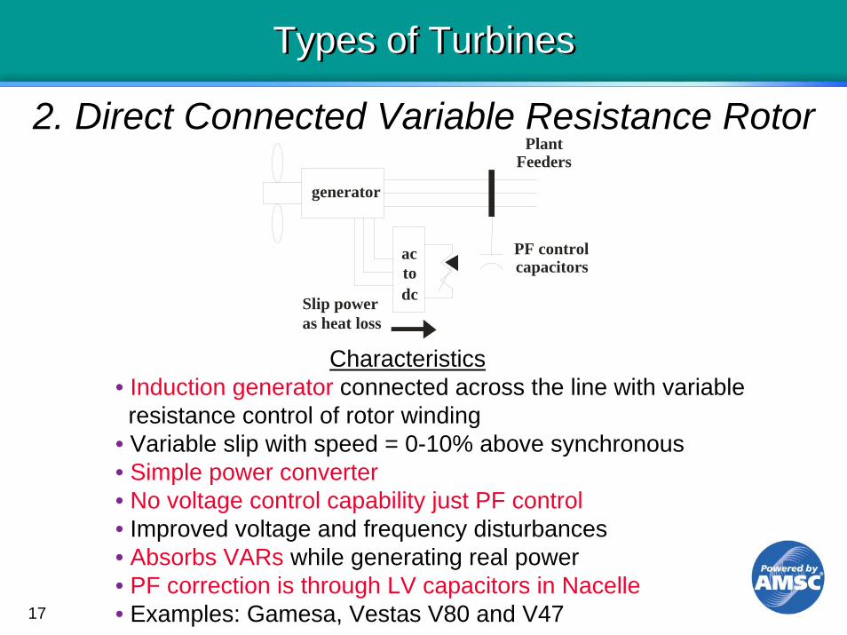
2. Direct Connected Variable Resistance Rotor
generator
Slip poweras heat loss
PlantFeeders
PF controlcapacitors
actodc
Characteristics• Induction generator connected across the line with variable resistance control of rotor winding
• Variable slip with speed = 0-10% above synchronous• Simple power converter• No voltage control capability just PF control• Improved voltage and frequency disturbances• Absorbs VARs while generating real power• PF correction is through LV capacitors in Nacelle• Examples: Gamesa, Vestas V80 and V47
18
Types of TurbinesTypes of Turbines
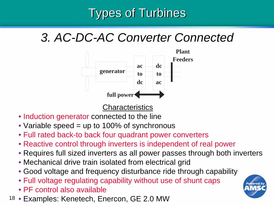
3. AC-DC-AC Converter Connected
generator
full power
PlantFeeders
actodc
dctoac
Characteristics• Induction generator connected to the line• Variable speed = up to 100% of synchronous• Full rated back-to back four quadrant power converters• Reactive control through inverters is independent of real power• Requires full sized inverters as all power passes through both inverters• Mechanical drive train isolated from electrical grid• Good voltage and frequency disturbance ride through capability• Full voltage regulating capability without use of shunt caps• PF control also available• Examples: Kenetech, Enercon, GE 2.0 MW

19
Types of TurbinesTypes of Turbines
4. Doubly Fed Induction Generator (DFIG)
generator
partial power
PlantFeeders
actodc
dctoac
Characteristics• Induction Generator connected across the line with variable frequency and voltage control of rotor windings
• Variable speed = +/-30% of synchronous• Partially rated power converters with reactive control through converters
• Requires smaller (~30% rated) converters but adds slip rings togenerator
• Good voltage and frequency disturbance ride through capability• Full voltage regulating capability without use of shunt caps• Examples: Vestas V90, GE 1.5 MW

20
Types of TurbinesTypes of Turbines
5. Synchronous Generator
Characteristics• Three-phase synchronous generator• No power electronics• Speed = Synchronous • Uses SuperGEAR™ technology - Hydrodynamic controlled component added to the standard gearbox that supplies constant speed to the synchronous generator• Good voltage and frequency disturbance ride through capability• Reactive control by changing the field voltage• Full voltage regulating capability without use of shunt caps• Examples: Windtec™ WT1650sg
21
Grid Integration Issues for Wind - IMPACTSGrid Integration Issues for Wind - IMPACTS
• Impacts of wind farms on the utility transmission system and distribution systems
• Impacts of utilities on wind farms
• Impacts on planning and modeling

22
Impacts on the Transmission GridImpacts on the Transmission Grid
• High VAR consumption (induction machines)
• Voltage fluctuations
• Inability to regulate voltage
• Tripping off due to either sudden low or high voltage
• Changes in wind speed can cause sudden power output changes
• Frequency issues

23
Impacts on the Distribution GridImpacts on the Distribution Grid
• Voltage sags due to inrush current at startup
• Voltage flicker due to tower shadowing effects or power output changes
• Harmonics

24
Impacts of Utility on Wind FarmsImpacts of Utility on Wind Farms
• Unique or unusual interconnection requirements
• Tripping of turbines due to variations in steady state voltage on transmission grid (+/-10%)- Requires LTC on power transformer(s)- Adds cost to collector grid design
• Gearbox damage due to sudden voltage changes on transmission grid – large cap or reactor banks
• Tripping of wind farm due to sudden voltage sag on transmission grid
• Phase voltage imbalance
• Harmonics
25
Impacts on Planning and ModelingImpacts on Planning and Modeling
• Wind turbine/collector system/utility model data is difficult to get
• System configuration changes- Developed in pieces or stages with
different turbines in each stage - May have separate 34.5 kV buses- Unavailability of collector grid design
information
26
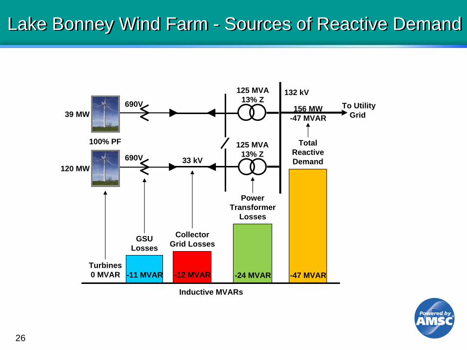
Lake Bonney Wind Farm - Sources of Reactive DemandLake Bonney Wind Farm - Sources of Reactive Demand
To UtilityGrid
690V
690V132 kV
33 kV
125 MVA13% Z
156 MW-47 MVAR39 MW
100% PF
120 MW
Turbines0 MVAR -11 MVAR
GSULosses
-12 MVAR
CollectorGrid Losses
-24 MVAR
PowerTransformer
Losses
TotalReactiveDemand
-47 MVAR
125 MVA13% Z
Inductive MVARs

27
Sources of Voltage Variation at Wind Farm Sources of Voltage Variation at Wind Farm
600V
115 kV60/90 MVA
9% Z
P.O.I.Ind. GenPF=90% 34.5 kV
Transmission operating range:0.95 - 1.05 pu continuous0.90 – 1.10 pu emergency
Wind turbine continuous voltageoperating range:0.90 - 1.10 pu continuous
1-2% voltage drop
+/-2% voltage rise/drop
1-3% voltage drop
+/-2% voltage rise/drop
Net PF=97-100%
Sum of voltage variability at turbines = 30% or more

28
Managing Voltage Regulation and Variability at the Wind Farm
Managing Voltage Regulation and Variability at the Wind Farm
600V
115 kV60/90 MVA
9% Z34.5 kV
P.O.I.Ind. GenPF=90%
• Add +/- 10% LTC• Use Lower Z transformer
Net PF=97-100%
4 MVARD-VARsystem
• Add collector based Dynamic reactive solution• Use D-VAR® system to regulate transmission system voltage
Regulatingcapacitorsunder D-VARsystem’s control
Sum of voltage variability at turbines < 10% at turbines
29
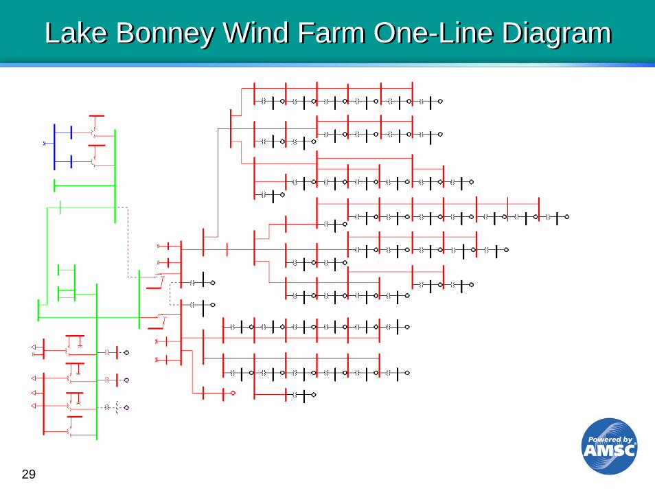
Lake Bonney Wind Farm One-Line Diagram Lake Bonney Wind Farm One-Line Diagram

30
Interconnection Requirements for Wind Farms

31
Typical Utility Interconnection RequirementsTypical Utility Interconnection Requirements
1. ERCOT2. Alberta3. Exelon4. Pacificorp5. Xcel6. Sask Power7. SDGE8. HELCO9. IESO10. S. Australia
+/-95% @ HV+90/-95%@ Dist V+95/100% @HV100% PF@HV POI100% @HV POI R+90%/-95%+90%/-95%100%/-88%@ HV+90%/-95%+/-93% @ HV POI
NoneEon NetzNoneNoneWorst faults Post Fault Recov. WECC 20%/20~Worst faultsWorst FaultHVRT/LVRT
HV BusHV BusHV BusDist BusHV Bus RDist BusHV BusHV BusHV BusHV Bus
UtilityPower Factor Requirements
Ride ThruRequirements
VoltageRegulation
POI: Point of InterconnectionWECC: Western Electricity Coordinating CouncilLVRT: Low Voltage Ride ThroughHVRT: High Voltage Ride Through

32
USA - Joint NERC/ FERC Interconnection Standardsfor Wind Energy (Dec 2005)
USA - Joint NERC/ FERC Interconnection Standardsfor Wind Energy (Dec 2005)
• Power factor of +/- 95% at the point of interconnection
• Voltage regulation capability• Low Voltage Ride Through (LVRT) down to zero
remaining voltage for: - 3 phase faults at high side of power transformer
cleared in 4-9 cycles- Single line-ground faults with delayed clearing - Need to be supported by case specific studies
33
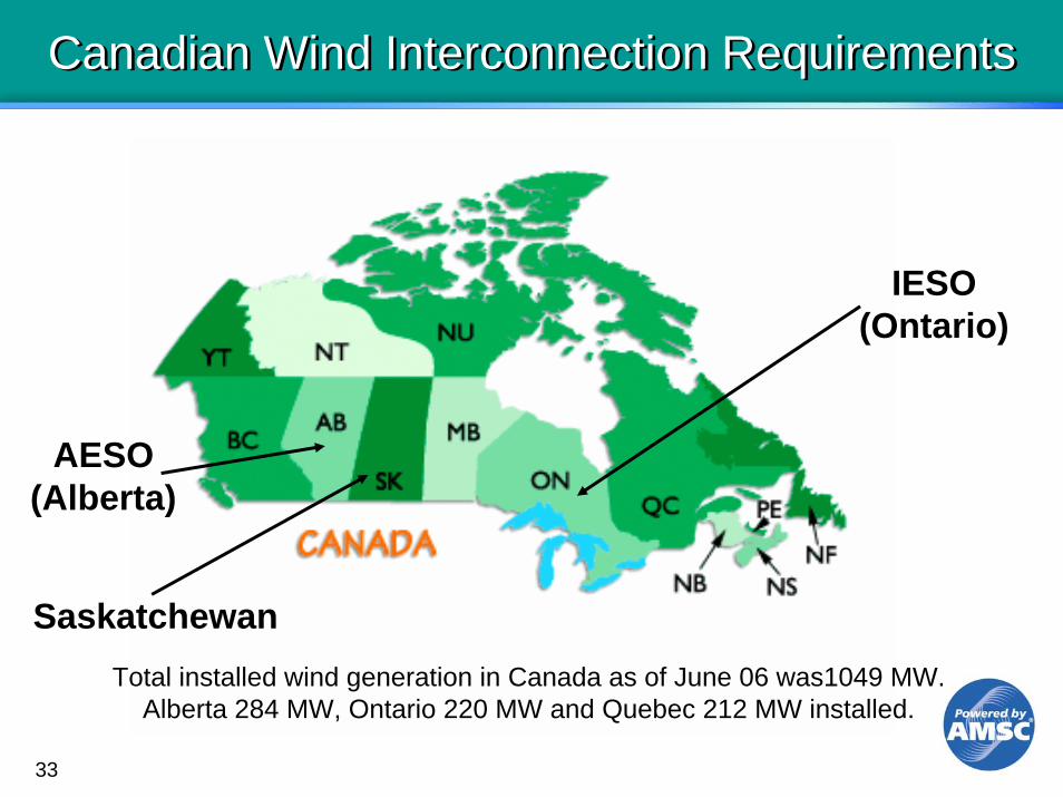
Canadian Wind Interconnection RequirementsCanadian Wind Interconnection Requirements
AESO(Alberta)
IESO(Ontario)
SaskatchewanTotal installed wind generation in Canada as of June 06 was1049 MW.
Alberta 284 MW, Ontario 220 MW and Quebec 212 MW installed.

34
Additional Utility RequirementsAdditional Utility Requirements
• Wind farm dynamic compensation system to meet post fault voltage recovery targets
• Provide dynamic PF control and susceptance control
• Provide high voltage ride through at voltages up to 130-140%
• Regulate voltage at remote points • Remain on line during emergency conditions
(Voltage range 0.90-1.10 pu)

35
Options to Address these StandardsOptions to Address these Standards
• Add capability within the wind generator turbine itself
• Add equipment at the collector bus level
• Add a combination of improved turbine capability plus some equipment at the collector bus
• Add equipment at the HV point of common coupling.
36
A Solution at the Collector BusHas Many Advantages
A Solution at the Collector BusHas Many Advantages
• Less expensive for larger wind installations
• Provides full voltage regulation capability even when wind plant is not generating
• Allows for a more flexible collector grid design
• Allows a wider voltage control range for the utility
• Solution is modular and expandable

37
D-VAR® System - Dynamic VAR DeviceD-VAR® System - Dynamic VAR Device
• Fully Integrated STATCOM with proprietary overload capability of 2.67 times its continuous rating
• Provides dynamic reactive capability – both leading and lagging
• D-VAR system can seamlessly switch other capacitors and reactors as part of a larger dynamic solution
• 33 wind farms use D-VAR systems for- PF correction- Voltage regulation- LVRT - HVRT

38
D-VAR® System Basics….D-VAR® System Basics….
Proprietary power electronics technology
Each phase is individually controlled
D-VAR systems mitigate wide variety of voltage and power quality related transmission problems
39
Why Integrating Wind Generation with Transmission is so Difficult

40
Asynchronous Generation Must Follow the Same Rules as Synchronous Generation to Connect
Asynchronous Generation Must Follow the Same Rules as Synchronous Generation to Connect
Coal, Gas and Hydro Plants(Synchronous Generators)
• Transmission added to move generation to load center
• Machines are synchronous, providing dispatchable real and reactive power
• Machines provide excellent voltage and frequency control.
Wind Generating Plants (Induction Generators)
• Minimal transmission added to support remote wind generation
• Asynchronous machines • Wind generation is non-
dispatchable, generally has limited reactive power control, and marginal voltage ride-through
Transmission System
(Operating Criteria)

41
Simulation Tools and UsesSimulation Tools and Uses
It is important to use the right tool for the right job
• Siemens/PTI PSS/E, GE PSLF- Load Flow, Stability, PF, LVRT, HVRT
• PSCAD - EMT, Switching transients, Harmonics
• DigSilent Powerfactory – EMT, LF, Stability, Short Circuit, System Protection

42
Wind Turbine Software Model Availability
Wind Turbine Software Model Availability
• PSS/E – 4 turbine models publicly available- Two for GE WTGs and two for Vestas WTGs- Models have been developed for many other manufacturers and
are available for release with approval by manufacturer• PSLF – 4 turbine models publicly available
- GE 1.5 and 3.6 MW - Vestas V80 and V47
• Turbine Manufacturers reluctant to share data with competitors - GE PSLF is part of GE who makes GE Wind turbines- PTI is part of Siemens who makes Siemens (Bonus) turbines
• PTI is in the process of developing a generic wind turbine model for each of the four different types of WTG we saw earlier.
• For specific wind farm studies, use the manufacturers model and data, and for the NERC data base, use the PTI generic wind turbine model with the manufacturer given data.
43
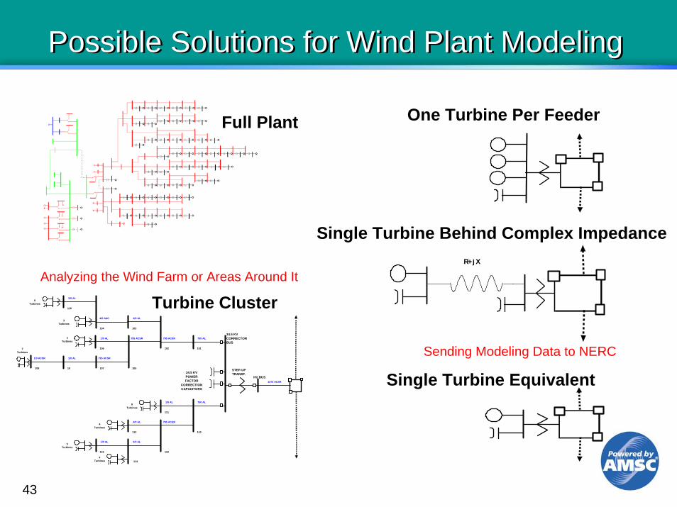
Possible Solutions for Wind Plant ModelingPossible Solutions for Wind Plant Modeling
R+ j X
1/0 AL
4/0 AAC 4/0 AL
1/0 AL 795 ACSR 795 ACSR 750 AL
1/0 ACSR 1/0 AL 795 ACSR
1/0 AL 750 AL
4/0 AL 795 ACSR
1/0 AL 4/0 AL
1272 ACSR
6Turbines
3Turbines
4Turbines
7Turbines
8Turbines
4Turbines
5Turbines
4Turbines
HV BUS
34.5 KVCORRECTORBUS
101102
103104
116
105
106
10710109
110
111
112
113
115
114
STEP-UPTRANSF.34.5 KV
POWERFACTOR
CORRECTIONCAPACITORS
Turbine Cluster
One Turbine Per Feeder
Single Turbine Behind Complex Impedance
Single Turbine Equivalent
Sending Modeling Data to NERC
Full Plant
Analyzing the Wind Farm or Areas Around It

44
Lake Bonney Wind Farm One-Line Diagram Lake Bonney Wind Farm One-Line Diagram
45
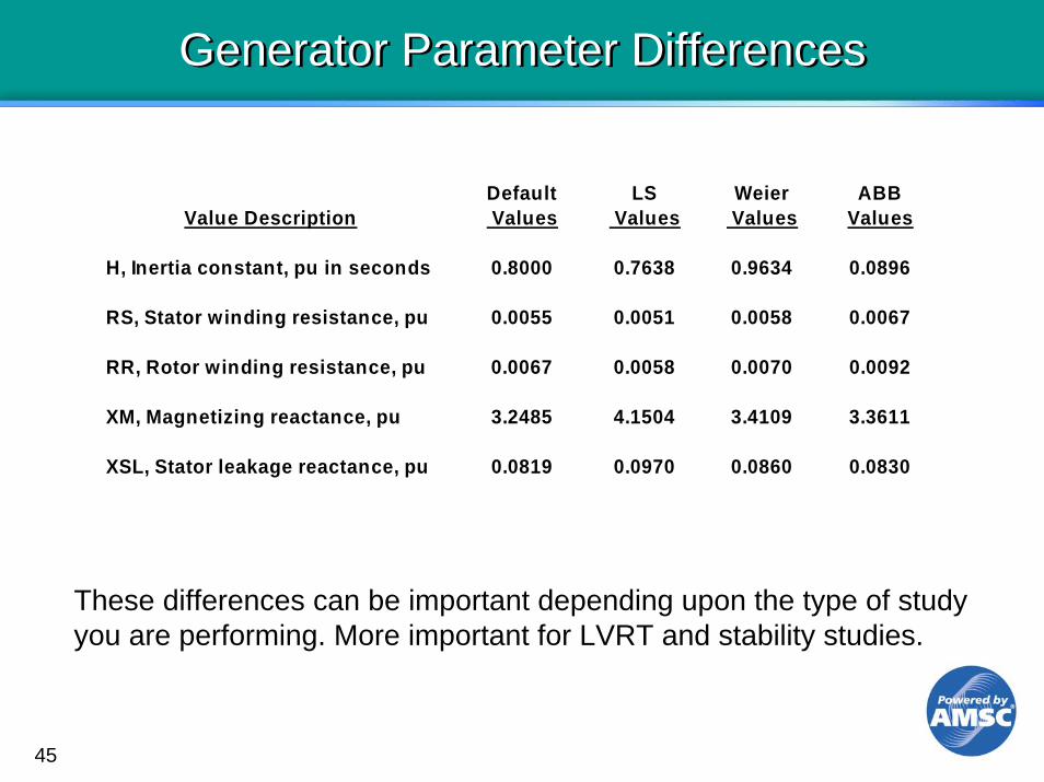
Generator Parameter DifferencesGenerator Parameter Differences
Default LS Weier ABB Value Description Values Values Values Values
H, Inertia constant, pu in seconds 0.8000 0.7638 0.9634 0.0896
RS, Stator winding resistance, pu 0.0055 0.0051 0.0058 0.0067
RR, Rotor winding resistance, pu 0.0067 0.0058 0.0070 0.0092
XM, Magnetizing reactance, pu 3.2485 4.1504 3.4109 3.3611
XSL, Stator leakage reactance, pu 0.0819 0.0970 0.0860 0.0830
These differences can be important depending upon the type of studyyou are performing. More important for LVRT and stability studies.

46
Integration of Wind into the Grid using Dynamic Reactive Compensation
An example of where the AMSC D-VAR® system has been successfully used to address power factor, voltage regulation and various forms of low & high voltage ride through problems

47
D-VAR Application D-VAR Application
Lake Bonney Wind Farm Phase 2Australia
Voltage Regulation andHigh Voltage Ride Through
48
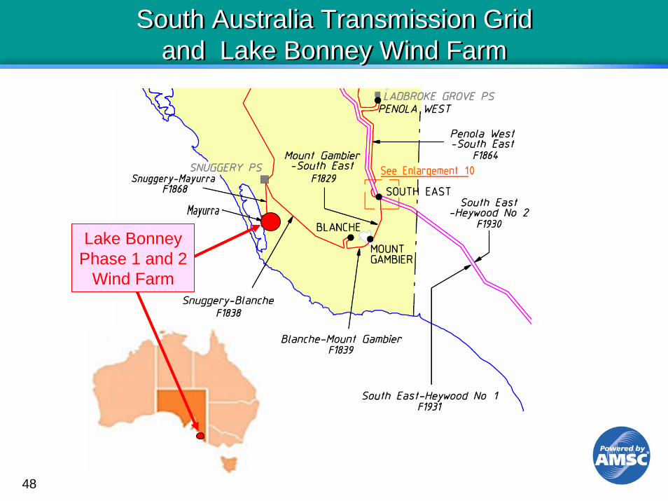
South Australia Transmission Grid and Lake Bonney Wind Farm
South Australia Transmission Grid and Lake Bonney Wind Farm
Lake BonneyPhase 1 and 2
Wind Farm

49
Lake Bonney 1 and 2 Wind Farms (240 MW total)
Lake Bonney 1 and 2 Wind Farms (240 MW total)
Lake Bonney 1 had no reactive compensation equipment installed.
T160/125 MVA132-33 kV
Mayurra Substation132 kV
33 kV
Existing - LBI46 Vestas V66
81 MW
To SnuggerySubstation
T260/125 MVA132-33 kV
N.O.
New - LB213 Vestas V90
39 MW
New - LB240 Vestas V90
120 MW
To South East SubstationVia Snuggery

50
ESCOSA - Wind Interconnection RequirementsESCOSA - Wind Interconnection Requirements
Requirements can be met primarily by installing dynamic and static reactive resources.
• Capable of +/-93% PF at high side of power transformer at full generation.
• Half of PF correction capability shall be dynamic.
• Reactive output proportional to generation level.
• Regulate transmission system voltage.
• Avoid tripping wind farm for nearby transmission grid faults and high voltage (LVRT, HVRT).
• Restore transmission system post fault voltage to a minimum of 90%.

51
LB2 159 MW Wind Farm - Sources of Reactive Losses at Full GenerationLB2 159 MW Wind Farm - Sources
of Reactive Losses at Full Generation
To UtilityGrid
690V
690V132 kV
33 kV
125 MVA13% Z
156 MW-47 MVAR39 MW
100% PF
120 MW
Turbines0 MVAR -11 MVAR
GSULosses
-12 MVAR
CollectorGrid Losses
-24 MVAR
PowerTransformer
Losses
TotalReactiveDemand
-47 MVAR
125 MVA13% Z
Inductive MVARs
Bottom Line - Add 47 MVAR to the capacitive reactive compensation target value.

52
Lake Bonney 2 Reactive Compensation Requirements at Full Generation
Lake Bonney 2 Reactive Compensation Requirements at Full Generation
Target Requirements Capacitive Inductive• +/-93% PF at 132 kV 63 63
• Include reactive losses- GSU transformer 12 -12- 33 kV collector grid 11 -11- 132-33 kV transformers 24 -24
Total Reactive Required 110 16
50% Dynamic 55 850% Non-dynamic 55 8
47MVAR
53
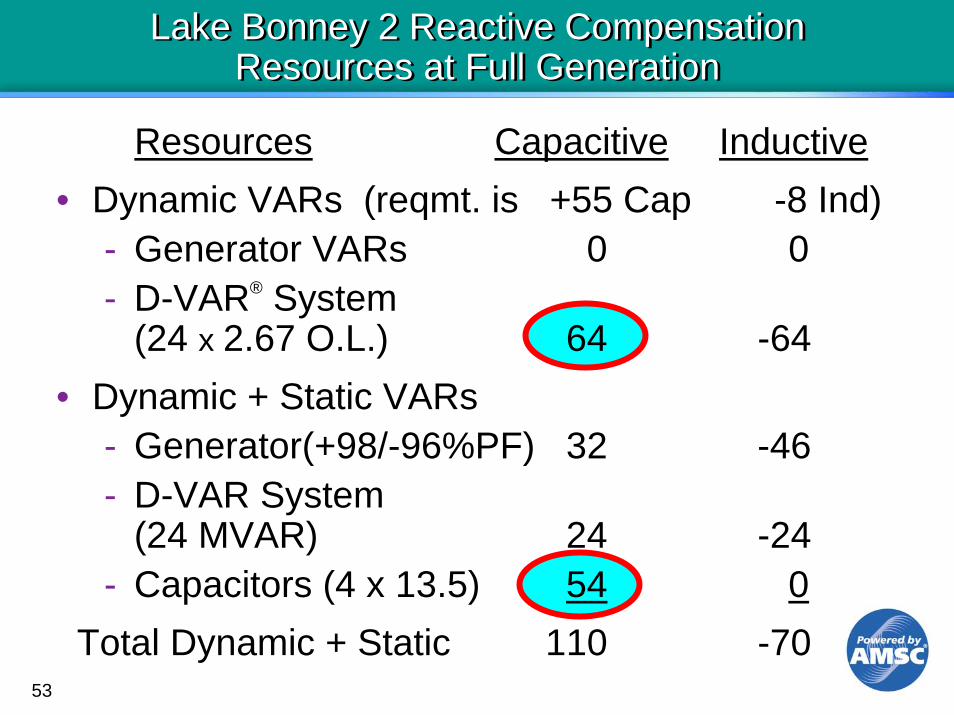
Lake Bonney 2 Reactive CompensationResources at Full Generation
Lake Bonney 2 Reactive CompensationResources at Full Generation
Resources Capacitive Inductive• Dynamic VARs (reqmt. is +55 Cap -8 Ind)
- Generator VARs 0 0- D-VAR® System
(24 x 2.67 O.L.) 64 -64• Dynamic + Static VARs
- Generator(+98/-96%PF) 32 -46- D-VAR System
(24 MVAR) 24 -24- Capacitors (4 x 13.5) 54 0
Total Dynamic + Static 110 -70

54
Lake Bonney 1 and 2 Wind Farms and AMSC’s D-VAR® Solution
Lake Bonney 1 and 2 Wind Farms and AMSC’s D-VAR® Solution
To SnuggerySubstation
To South East SubstationVia Snuggery
T160/125 MVA132-33 kV
T260/125 MVA132-33 kV
33 kV
ExistingLBI
80 MW
Breakers
N.O.
NewLB2
39 MW
NewLB2
120 MW3x4 MVAD-VAR®Systems
3x4 MVAD-VAR
Systems
2x13.5 MVARCap Banks
2x13.5 MVARCap Banks
VBM
V90 P.F. Control
Mayurra Substation132 kV
Voltage M
onitoring
MVARControl
PT
D-VAR SystemReactive Control
55
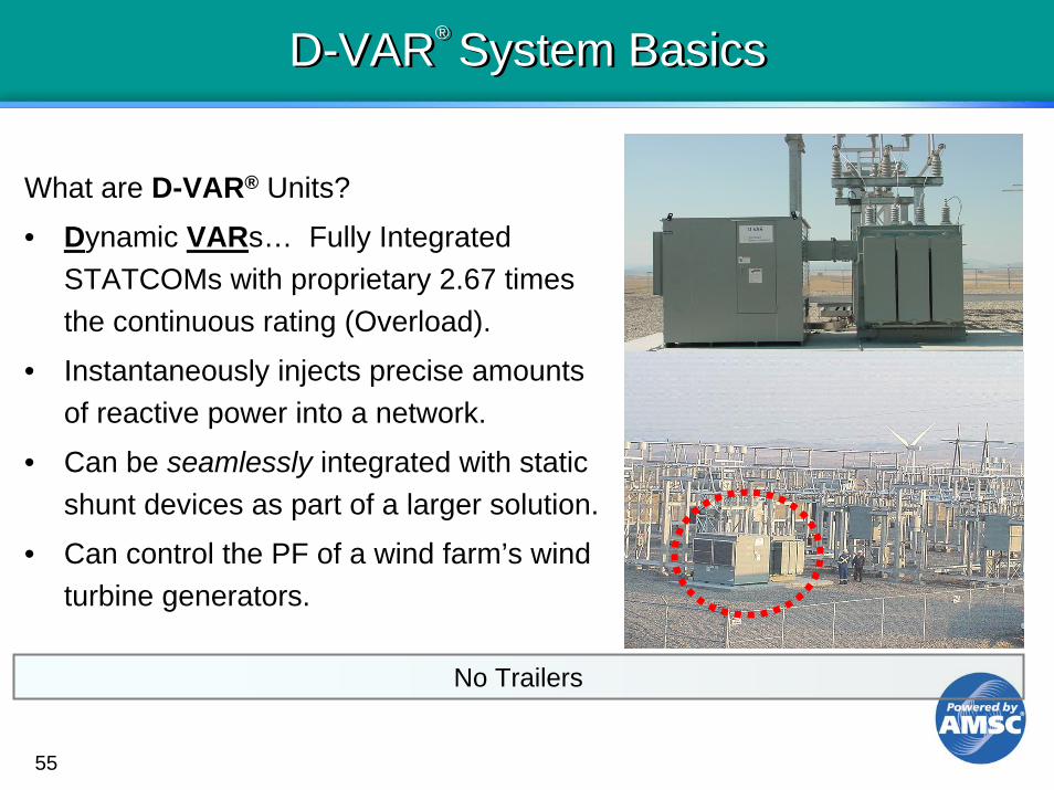
D-VAR® System BasicsD-VAR® System Basics
What are D-VAR® Units?
• Dynamic VARs… Fully Integrated STATCOMs with proprietary 2.67 times the continuous rating (Overload).
• Instantaneously injects precise amounts of reactive power into a network.
• Can be seamlessly integrated with static shunt devices as part of a larger solution.
• Can control the PF of a wind farm’s wind turbine generators.
No Trailers

56
Innovative Approaches to Addressing Wind Interconnection Requirements
Innovative Approaches to Addressing Wind Interconnection Requirements
• Use D-VAR® system’s overload capability to address transient reactive requirements –during both low and high voltage events
• Use slower speed power factor correction capacitors to address post fault voltage issues
• Use turbine variable power factor (PF) output capability to meet PF requirements

57
High Voltage Ride Through PCC and WTG CapabilityHigh Voltage Ride Through PCC and WTG Capability
Time In Seconds
Vol
tage
in P
er U
nit
Time In Seconds
58
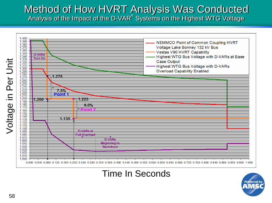
Method of How HVRT Analysis Was ConductedAnalysis of the Impact of the D-VAR® Systems on the Highest WTG Voltage
Method of How HVRT Analysis Was ConductedAnalysis of the Impact of the D-VAR® Systems on the Highest WTG Voltage
Time In Seconds
Time In Seconds
Vol
tage
in P
er U
nit

59
Post Fault Voltage Recovery SimulationShowing Innovative Solution Results
Post Fault Voltage Recovery SimulationShowing Innovative Solution Results
Light Load – 2 Phase Fault Snuggery-Blanche 132 kV Line

60 60
-100 -80 -60 -40 -20 0 20 40 60 80 100
150
125
100
75
50
CapacitiveInductive MVAR
LB2
Gen
erat
ion
in M
W
D-VAR,Caps, and I2X losses
PF Caps54 MVAR
175
25V90 PF Control
32 MVAR
D-VAR, Caps, I2X losses,
and V90 PF
D-VAR24 MVAR
D-VAR24 MVAR
V90 PF Control46 MVAR
63 11063110
D-VAR and I2X losses
D-VAR I2X losses,and V90 PF
Lake Bonney Reactive Requirements and Capability as a Function of Generation Level
61
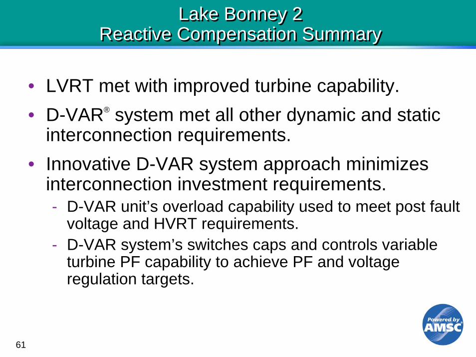
Lake Bonney 2Reactive Compensation Summary
Lake Bonney 2Reactive Compensation Summary
• LVRT met with improved turbine capability.• D-VAR® system met all other dynamic and static
interconnection requirements.• Innovative D-VAR system approach minimizes
interconnection investment requirements.- D-VAR unit’s overload capability used to meet post fault
voltage and HVRT requirements.- D-VAR system’s switches caps and controls variable
turbine PF capability to achieve PF and voltage regulation targets.

62
Recent AMSC D-VAR® System Installations in AsiaRecent AMSC D-VAR® System Installations in Asia
Lake Bonney 2
White Hill
Tararua T3
New Zealand
