report on the common information model (cim) extensible
TRANSCRIPT

Report on the Common InformationModel (CIM) Extensible Markup Language(XML) Interoperability Test #2
The Power of the CIM to Exchange Power SystemModels
Technical Report


EPRI Project ManagerD. Becker
EPRI • 3412 Hillview Avenue, Palo Alto, California 94304 • PO Box 10412, Palo Alto, California 94303 • USA800.313.3774 • 650.855.2121 • [email protected] • www.epri.com
Report on the Common InformationModel (CIM) Extensible MarkupLanguage (XML) InteroperabilityTest #2The Power of the CIM to Exchange Power SystemModels
1006216
Technical Progress, October 2001

DISCLAIMER OF WARRANTIES AND LIMITATION OF LIABILITIES
THIS DOCUMENT WAS PREPARED BY THE ORGANIZATION(S) NAMED BELOW AS ANACCOUNT OF WORK SPONSORED OR COSPONSORED BY THE ELECTRIC POWER RESEARCHINSTITUTE, INC. (EPRI). NEITHER EPRI, ANY MEMBER OF EPRI, ANY COSPONSOR, THEORGANIZATION(S) BELOW, NOR ANY PERSON ACTING ON BEHALF OF ANY OF THEM:
(A) MAKES ANY WARRANTY OR REPRESENTATION WHATSOEVER, EXPRESS OR IMPLIED, (I)WITH RESPECT TO THE USE OF ANY INFORMATION, APPARATUS, METHOD, PROCESS, ORSIMILAR ITEM DISCLOSED IN THIS DOCUMENT, INCLUDING MERCHANTABILITY AND FITNESSFOR A PARTICULAR PURPOSE, OR (II) THAT SUCH USE DOES NOT INFRINGE ON ORINTERFERE WITH PRIVATELY OWNED RIGHTS, INCLUDING ANY PARTY'S INTELLECTUALPROPERTY, OR (III) THAT THIS DOCUMENT IS SUITABLE TO ANY PARTICULAR USER'SCIRCUMSTANCE; OR
(B) ASSUMES RESPONSIBILITY FOR ANY DAMAGES OR OTHER LIABILITY WHATSOEVER(INCLUDING ANY CONSEQUENTIAL DAMAGES, EVEN IF EPRI OR ANY EPRI REPRESENTATIVEHAS BEEN ADVISED OF THE POSSIBILITY OF SUCH DAMAGES) RESULTING FROM YOURSELECTION OR USE OF THIS DOCUMENT OR ANY INFORMATION, APPARATUS, METHOD,PROCESS, OR SIMILAR ITEM DISCLOSED IN THIS DOCUMENT.
ORGANIZATION(S) THAT PREPARED THIS DOCUMENT
Xtensible Solutions, Inc.
ORDERING INFORMATION
Requests for copies of this report should be directed to EPRI Customer Fulfillment, 1355 Willow Way,Suite 278, Concord, CA 94520, (800) 313-3774, press 2.
Electric Power Research Institute and EPRI are registered service marks of the Electric PowerResearch Institute, Inc. EPRI. ELECTRIFY THE WORLD is a service mark of the Electric PowerResearch Institute, Inc.
Copyright © 2001 Electric Power Research Institute, Inc. All rights reserved.

iii
CITATIONS
This report was prepared by
Xtensible Solutions, Inc.18125 23rd Avenue NorthPlymouth, MN 55447
AuthorT. L. Saxton
This report describes research sponsored by EPRI.
The report is a corporate document that should be cited in the literature in the following manner:
Report on the Common Information Model (CIM) Extensible Markup Language (XML)Interoperability Test #2: The Power of the CIM to Exchange Power System Models, EPRI, PaloAlto, CA: 2001. 1006216.


v
REPORT SUMMARY
The Control Center Application Program Interface (CCAPI) and Common Information Model(CIM) translated into Extensible Markup Language (XML) provide a very important standard forexchanging power system models. Interoperability tests conducted in December 2000 validatedthe use and acceptance of this standard by a number of suppliers who provide products to theelectric utility industry. A second set of interoperability tests conducted in April 2001 extendedthis validation to include the transfer of a large real-world power system model and the runningof power flow solutions on exchanged models. This report presents results of these tests.
BackgroundEPRI spearheaded an industry-wide CCAPI effort to develop open, interoperable applications forEnergy Management Systems (EMS) in energy control centers through use of standardizedinterfaces. Central to the CCAPI concept is CIM, which defines the essential data structure of apower system model. The North American Electric Reliability Council (NERC) had beensearching for the best way to exchange power system models electronically, and CIM using theindustry standard language XML offered the best solution. The CCAPI project initiated an effortto map CIM into XML, which is supported by all major software platforms. Use of the ResourceDescription Framework (RDF) schema and syntax to organize XML also was adopted. Tovalidate XML and RDF for model exchange, a series of interoperability tests between productsfrom different suppliers was planned.
ObjectiveTo report results of the second set of interoperability tests performed in Las Vegas on April 29 -May 1, 2001.
ApproachThe project team prepared a formal set of test procedures to test the ability of vendor products tocorrectly import and export sample power system model files. After a period of preparation andpreliminary testing, five vendors gathered in Las Vegas in April 2001 to have an impartialobserver test their products. Four sample model files were available for this test (PsyCor smallmodel [2 bus], ABB 40 bus, Alstom 60 bus, and Siemens 100 bus) in addition to a real-life largescale model from Duke Energy with over 1700 substations.
ResultsThe report provides a summary of the test process and results. The test process is first explainedto aid in understanding test results, which are reported in a series of test matrices. For purposesof reporting on the tests, results are loosely organized into three categories:

vi
1. Basic import/export of model files - tests an individual product’s ability to correctly import and export powersystem model files based on CIM XML standards. One test goal was to validate changes made to CIM since thelast set of interoperability tests.
2. Interoperability test - tests the ability of one vendor’s product to correctly import a sample model previouslyexported by another vendor’s product using CIM XML standards.
3. Solution test - verifies correct content of model files and exchange and transformation ofpower system model files including generation and load through execution of power flowapplications. Verification was accomplished by comparing solutions before and aftertransformation and model exchange. Two of three vendors with power flow applicationssuccessfully completed all significant solution tests.
A description of tested vendors’ products is provided. A summary of problems uncovered duringtesting and their resolution also is included.
EPRI PerspectiveCCAPI compliance offers control center managers the flexibility to combine—on one or moreintegrated platforms—software that best meets their energy company’s needs for systemeconomy and reliability. This compatibility allows managers to upgrade, or migrate, their EMSsystems incrementally and quickly, while preserving prior utility investments in customsoftware. Migration reduces upgrade costs by 40 percent or more and enables energy companiesto gain strategic advantages by using new applications as they become available.
At the same time, as market forces accelerate the pace of the changing business environment forenergy companies, the need for greater business and operating flexibility also has increased.Such responsiveness requires that all members of a business enterprise pool their talents andresources. An energy company’s information is one of its most valuable resources, and energycompanies are working to improve accessibility to this critical resource, whether it be real-timedata on power system operation, energy billing information, or load forecasting data.
CCAPI/CIM-enhanced EMSs foster an interdisciplinary approach to conducting business byenabling interdepartmental teams to access a range of needed information via open systems.Hence, in innovative applications, energy companies are planning to implement CCAPI and CIMoutside the control center to reduce costs and improve customer service and staff productivity.EPRI continues to sponsor collaborative efforts to advance CCAPI and CIM capabilities forgreater information systems integration solutions—in the control center and beyond.
KeywordsApplication program interface Control centers Energy management systemsCommon information model CIM XMLData exchange Power system modelPower system reliability Power system security

vii
PREFACE
The reliability of the North American power grid is an increasingly visible topic in the newstoday. This is due in large part to the need to operate closer to available transmission capacitiesthan at any time in the history of the electric utility industry. Ever-increasing demand in the faceof reduced power plant construction is a major factor - evidence the recent rolling blackouts inCalifornia.
One way to tackle the reliability issue is to improve the models of the power system used tocalculate available transmission capacity, so that calculated capacities more nearly match realworld capacities. This permits operation closer to maximum capacity while avoiding unplannedoutages. One key to improved models is to have the capability to merge NERC regional modelsinto a combined model. Since these models reside in multiple, proprietary databases in SecurityCoordination Center EMSs located throughout North America, an information infrastructure thatfacilitates model exchange is an absolute necessity.
One initiative underway to address this need is based on the Common Information Model (CIM)standards that EPRI helped develop as part of the Control Center Application Program Interface(CCAPI) project. The CIM has been translated into the industry standard Extensible MarkupLanguage (XML), which permits the exchange of models in a standard format that any EMS canunderstand using standard Internet and/or Microsoft technologies. The North American ElectricReliability Council (NERC) recently mandated the use of this standard by Security CoordinationCenters (SCCs) to exchange models by September 2001, adding urgency to the deployment ofproducts that support these standards.
This report presents the results of the second interoperability tests using these standards toexchange power system models between products from five different vendors. The goal of thisreport is to raise awareness of the importance and status of this effort to encourage early adoptionby additional product suppliers and energy managers.
David L BeckerEPRIMay 2001

ix
ABSTRACT
On April 29 � May 1, 2001 in Las Vegas, Nevada, five software vendors serving the electricutility industry met for the second time to continue testing the capability of their softwareproducts to exchange and correctly interpret power system model data based on the CIM(Common Information Model). The CIM was developed by the EPRI CCAPI project and is nowbeing advanced as an international standard (draft IEC 61970-301 CIM Base). Each vendorpresent was required to exchange files with the other vendors and to demonstrate that theirsoftware correctly converted their proprietary representation of a power system model to/fromthe CIM XML format.
These interoperability tests address an important industry requirement established by NERC tobe able to transfer power system model data between Security Coordinators. NERC hasmandated the use of the Resource Description Framework (RDF) as the XML schema/syntax forthe CIM, which is defined in another CCAPI standard (draft IEC 61970-501 CIM RDF Schema).These tests demonstrated the use of this draft standard for this purpose and for any otherapplication where a standard way of representing power system models is needed, such ascombining multiple, proprietary-formatted power system models into a single merged internalmodel for an RTO.
Vendors participating in these tests included ABB, ALSTOM ESCA, Siemens, SISCO, andCIM-Logic. Xtensible Solutions prepared the test procedures, witnessed the test results, and willprepare a test report for EPRI. This is an important milestone in the CCAPI project and is thesecond in a series of planned interoperability tests for 2001 that will demonstrate additionalCCAPI capabilities.


xi
ACKNOWLEDGMENTS
EPRI wishes to thank the many people who worked hard to make this second CIM XMLinteroperability test a success. Not all people who contributed can be named here. However,EPRI would like to give special recognition to the following vendors and contractors:
• Steve Widergren, ALSTOM ESCA, for leadership, assistance with test procedurepreparation, and assistance in obtaining permission to use the Duke Energy power systemmodel
• Arnold deVos, Langdale Consultants, for test tools and preparation of the CIM UML andRDF schema files
• Joe Evans, PsyCor, for preparation of the small model, updating of NERC profile in the CIM,and provision of the LAN server for model management during the tests
• Mostafa Khadem, ABB, for preparation of the 40 bus model
• Rob Fairchild, ALSTOM, for preparation of the 60 bus model
• Kurt Hunter, Siemens, for preparation of the 100 bus model
• Robert Kingsmore, Duke Energy, for providing the 1700 substation large scale model
• All participants, for bringing enthusiasm and focused energy with a true spirit of cooperationto Las Vegas to make these tests a success
• The author apologizes if others deserving of special mention were not listed � it was notintentional.
In addition, EPRI acknowledges Terry Saxton, Xtensible Solutions, who prepared the test planand procedures, witnessed the tests and recorded the results, and wrote this report.
Dave BeckerEPRI


xiii
CONTENTS
1 INTRODUCTION.................................................................................................................. 1-1
Objectives of Interoperability Test....................................................................................... 1-1
Scope of Interoperability Test 2 .......................................................................................... 1-2
CIM 09b Validation Tests............................................................................................... 1-2
Scalability Tests............................................................................................................. 1-2
Solution Tests ................................................................................................................ 1-3
Scope of the CIM Tested ............................................................................................... 1-3
Organization of Report ....................................................................................................... 1-4
References......................................................................................................................... 1-4
2 THE TEST PLAN................................................................................................................. 2-1
Participating Vendors and Their Products........................................................................... 2-1
Test Approach.................................................................................................................... 2-2
Pretest Preparation........................................................................................................ 2-2
Basic Export/Import Process.......................................................................................... 2-2
On-Site Interoperability Test .......................................................................................... 2-3
Scalability and CIM 09b Validation Testing................................................................ 2-3
Solution Test ............................................................................................................. 2-4
Test Configuration ......................................................................................................... 2-6
3 TEST RESULTS .................................................................................................................. 3-1
Summary of Test Results ................................................................................................... 3-2
CIM 09b Validation ........................................................................................................ 3-2
Basic Import and Export ............................................................................................ 3-2
Interoperation ................................................................................................................ 3-3
Scalability ...................................................................................................................... 3-6
Duke Model Import and Export.................................................................................. 3-6
Interoperation with Duke Model................................................................................. 3-7
Solution Test.................................................................................................................. 3-8

xiv
Summary of Issues Identified .........................................................................................3-11
4 FUTURE INTEROPERABILITY TESTS.................................................................................4-1
A APPENDIX: PARTICIPANT PRODUCT DESCRIPTIONS................................................... A-1
ABB Data Engineering Tool (RDE) ...................................................................................... A-1
ALSTOM ESCA eTerra-Modeler and Study Powerflow ....................................................... A-1
eTerra Modeler ................................................................................................................ A-2
Study Powerflow.............................................................................................................. A-2
Modeling Conventions ..................................................................................................... A-2
CIM-Logic JCIM.................................................................................................................... A-2
Siemens Information Model Manager .................................................................................. A-3
SISCO Utility Integration Bus ............................................................................................... A-4
B APPENDIX: TEST CONFIGURATION DATA ...................................................................... B-1
Test Procedures................................................................................................................... B-1
CIM Baseline Version for Testing......................................................................................... B-1
RDF Syntax.......................................................................................................................... B-1
Test Files.............................................................................................................................. B-1
Tools .................................................................................................................................... B-2
File Transfer ......................................................................................................................... B-2
C APPENDIX: TEST ISSUES AND RESOLUTIONS............................................................... C-1
xv
LIST OF FIGURES
Figure 2-1 Export/Import Process Basics ..................................................................................2-3
Figure 2-2 CIM XML Interoperability Test Process Steps..........................................................2-4
Figure 2-3 Solution Test Process...............................................................................................2-5
Figure A-1 ABB's Data Engineering Tool (RDE)...................................................................... A-1
Figure A-2 SISCO Utility Integration Bus .................................................................................. A-4


xvii
LIST OF TABLES
Table 2-1 Participating Vendors and Their Products .................................................................2-1
Table 3-1 Description of Tests Performed .................................................................................3-1
Table 3-2 CIM 09b Validation Test Results on Individual Products ...........................................3-3
Table 3-3 Interoperation with Sample Models ...........................................................................3-5
Table 3-4 Scalability Test on Individual Products ......................................................................3-7
Table 3-5 Interoperation with Duke Energy Model.....................................................................3-8
Table 3-6 Solution Test Results...............................................................................................3-10
Table A-1 UIB Toolkit Version 1.0............................................................................................. A-5


1-1
1 INTRODUCTION
This document reports the results of the second CIM XML interoperability tests, which tookplace on April 29 � May 1, 2001 in Las Vegas, Nevada. Interoperability testing proves thatproducts from different vendors can exchange information and request services based on the useof the IEC standards that have been developed as an output of the CCAPI project.
The test required that participating products conform to the future IEC 61970-301 CIM Base,which is based on the CIM model file cimu09b.mdl and the future IEC 61970-501 CIM RDFSchema Version 4.
This test was the second in a series of CIM XML interoperability tests planned for the nearfuture (see Section 4 for future test plans).
Objectives of Interoperability Test
The objectives of the interoperability tests and demonstrations were to:
1. Demonstrate interoperability between different vendor products based on the CIM. Thisincludes applications from EMS as well as independently developed applications from thirdparty suppliers.
2. Verify compliance with the CIM for those CIM classes/attributes involved in the informationexchanges supported by the tests.
3. Demonstrate the exchange of power system models using the CIM and an RDF Schema andXML representation of the model data.
Secondary objectives included the following:
1. Validate the correctness and completeness of IEC draft standards, resulting in higher qualitystandards by removing discrepancies and clarifying ambiguities.
2. Provide the basis for a more formal interoperability and compliance test suite developmentfor CCAPI standards. This would eventually become part of set of UCA 2 test proceduresand facilities currently being developed by EPRI.
Introduction
1-2
Specific objectives for the second interoperability test fell into three categories:
1. Redo a portion of the small model exchange based on updated CIM version 09b to validatethe model changes from version 09a and the ability of participant�s products to handlechanges. This is referred to as the �CIM 09b Validation� test.
2. Transfer of larger, more realistic power system models which include generation and loads.This is referred to as the �scalability� test.
3. Execution of load flow/power flow applications to verify sufficiency of the model files (interms of having all necessary elements represented) and correctness of the transformationsto/from local representations of the models. This is referred to as the �solution� test.
Scope of Interoperability Test 2
This second interoperability test involved CIM XML file exchanges using model files similar tothe first tests, except that in a large scale power system model from Duke Energy was used inaddition to smaller sample model files and an updated version of the CIM was used (i.e., CIMversion 0u09b).
CIM 09b Validation Tests
To meet the first objective of validating the updated CIM version 09b, a subset of the sameprocedures used in the first interoperability test (after updating to add changes agreed to duringthe first test) were used.
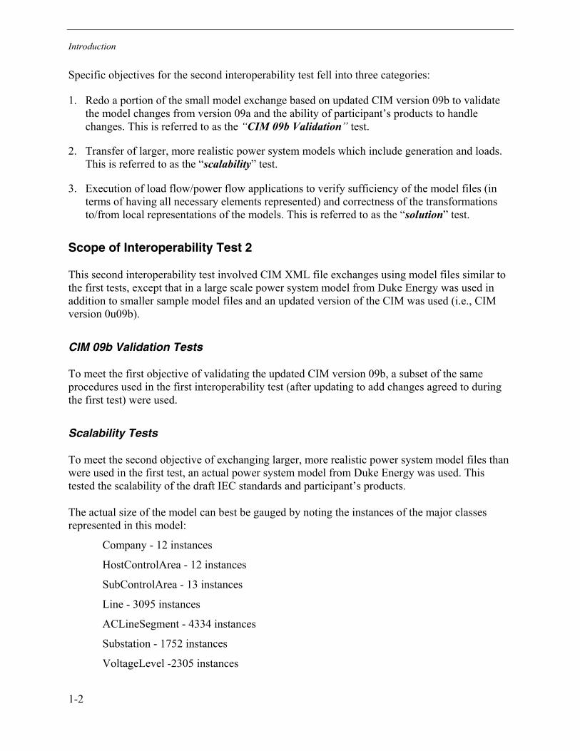
Scalability Tests
To meet the second objective of exchanging larger, more realistic power system model files thanwere used in the first test, an actual power system model from Duke Energy was used. Thistested the scalability of the draft IEC standards and participant�s products.
The actual size of the model can best be gauged by noting the instances of the major classesrepresented in this model:
Company - 12 instances
HostControlArea - 12 instances
SubControlArea - 13 instances
Line - 3095 instances
ACLineSegment - 4334 instances
Substation - 1752 instances
VoltageLevel -2305 instances
Introduction
1-3
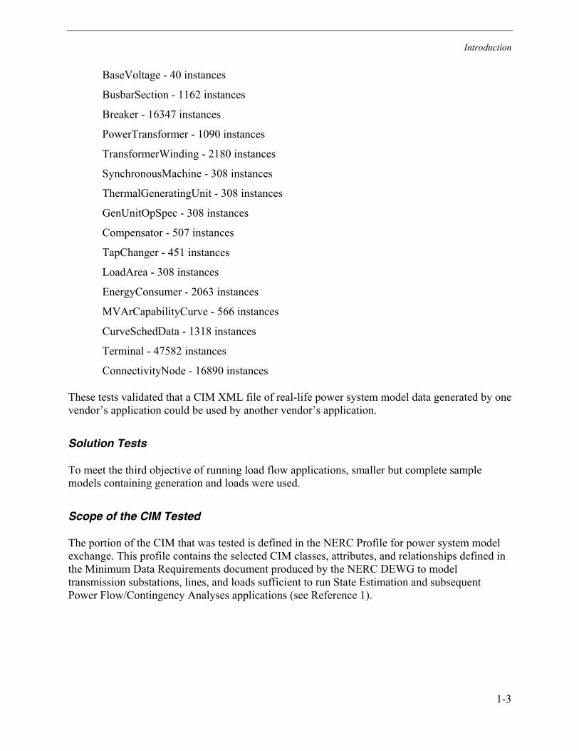
BaseVoltage - 40 instances
BusbarSection - 1162 instances
Breaker - 16347 instances
PowerTransformer - 1090 instances
TransformerWinding - 2180 instances
SynchronousMachine - 308 instances
ThermalGeneratingUnit - 308 instances
GenUnitOpSpec - 308 instances
Compensator - 507 instances
TapChanger - 451 instances
LoadArea - 308 instances
EnergyConsumer - 2063 instances
MVArCapabilityCurve - 566 instances
CurveSchedData - 1318 instances
Terminal - 47582 instances
ConnectivityNode - 16890 instances
These tests validated that a CIM XML file of real-life power system model data generated by onevendor�s application could be used by another vendor�s application.
Solution Tests
To meet the third objective of running load flow applications, smaller but complete samplemodels containing generation and loads were used.
Scope of the CIM Tested
The portion of the CIM that was tested is defined in the NERC Profile for power system modelexchange. This profile contains the selected CIM classes, attributes, and relationships defined inthe Minimum Data Requirements document produced by the NERC DEWG to modeltransmission substations, lines, and loads sufficient to run State Estimation and subsequentPower Flow/Contingency Analyses applications (see Reference 1).

Introduction
1-4
Organization of Report
This report presents results of the second CIM XML interoperability tests held in Las Vegas.
The introductory chapter presents the objectives and scope of these tests. Chapter 2 describes thetest plan that was followed and identifies the participating vendors and their products. Chapter 3presents the test results, beginning with a summary of each test step that was scored. The testscores, which are given as Pass, Pass with Errors, or Not Applicable, are organized in a series oftables. A summary of the significant results achieved are also provided. The three appendicescontain a description of the participant�s products used in the tests (Appendix A); the testconfiguration data, including specific versions of the CIM in UML and XML/RDF, samplemodel files, and test tools (Appendix B); and issues and resolutions that arose during the tests(Appendix C).
References
1. CPSM Minimum Data Requirements in Terms of the EPRI CIM, version 1.0
2. CIM XML Interoperability Test 2, Test Plan and Procedures, Revision 3, April 28, 2001.
3. Report on the First Common Information Model (CIM) Extensible Markup Language (XML)Interoperability Test, The Power of the CIM to Exchange Power System Models, ProductNumber 1006161, Final Report, February 2001.

2-1
2 THE TEST PLAN
Each application participating in this test was required to (1) generate and export a file thatconformed to the standards for the specific model data defined for the test and/or (2) import a filefrom another vendor�s product and correctly interpret the model data contained. A formal set oftest procedures were prepared and used to conduct and score the tests (see Reference 2). Inaddition, participants were also given the opportunity to run power flow solutions on theimported files as another way to validate the proper handling of imported models.
Participating Vendors and Their Products
Each participating vendor was required to use an actual product so that testing woulddemonstrate interoperability of real products. The participating vendors and their products arelisted in Table 2-1 below. Table 2-1 also describes the hardware platform and operating systemused.
Table 2-1Participating Vendors and Their Products
Vendor Product Name Platform OS
ABB DE400 SPIDER CIMData Engineering andOracle V. 8.1.6
DEC Alpha station500
UNIX 4.0F
ALSTOM GENESYS - eterra-Modeler and StudyPowerflow
IBM-compatibleLaptop PC
Windows 2000
CIM-Logic JCIM IBM-compatibleLaptop PC
Windows 2000
Siemens Spectrum InformationModel Manager(Engineering System)
IBM-compatibleLaptop PC
Windows 2000
SISCO Utility Integration Bus(UIB)
IBM-compatibleDesktop PC
Windows NT 4.0, SP6
A description of each product used in the tests is contained in Appendix A. These descriptionsalso explain how the CIM XML data is used in the product and how successful compliance withthe CIM XML format was demonstrated.

The Test Plan
2-2
Test Approach
As stated in the Introduction, there were three major categories of tests � a CIM 09b Validationtest, a Scalability test, and a Solution test. Participants were encouraged to perform either one,two, or all three of these tests.
The CIM 09b Validation and Scalability tests were performed by participants with the same classof products used in Interop Test 1 (i.e., modeling or browser tools alone were sufficient todemonstrate correct operation).
The Solution test, however, required the use of power flow applications to operate on the powersystem models to calculate power flow solutions. Solutions obtained were used to validate thecorrect transfer and transformation of model files between participants. The Solution tests usedthe same model files as the CIM 09b Validation tests to create confidence that the appropriateinformation is being exchanged and interpreted correctly, thus avoiding performance issuesassociated with large models, whose solutions can be checked in future tests.
Pretest Preparation
Prior to the official witnessed interoperability tests, sample model files were prepared by PsyCor(small model), ABB (40 bus), ALSTOM (60 bus) and Siemens (100 bus) to be used during thetests. These files contained instances of the CIM classes, attributes, and relationships defined inthe NERC profile. For example, the PsyCor model contained two substations connected by asingle AC line. The ALSTOM file, termed the 60 bus model, contained 29 substationsinterconnected by 41 AC lines. Participants applications were only tested for the entitiesspecified in the NERC profile. The models were intentionally kept small to ensure that file sizeand performance would not be issues in these first tests.
The Duke Energy model used for the Scalability test, on the other hand, contained 1752substations with 3095 AC lines (see Introduction for more details on this model). Because of thesensitive nature of real models, nominal generation and load values were used and non-disclosure agreements were signed by test participants to gain access to the models. The modelfile use was restricted to uses concerned only with interoperability testing.
All of the test files were available before the formal testing began to allow participants tocheckout and debug their software as well as to discover any discrepancies or errors in the filesthemselves.
Basic Export/Import Process
Figure 2-1 shows the process applied by the products under test to export and/or import CIMXML files (also referred to as CIM XML documents). For export, an XML/RDF version of theCIM is used by a product to convert a proprietary representation of one of the sample model filesinto a standard CIM XML representation of that model. The CIM XML document can then beviewed through a browser using an XSL Style Sheet to format the contents for human

The Test Plan
2-3
readability. Separate XML tools are used to validate the format of the file and the conformancewith XML and the RDF Syntax. An XML/RDF Validator tool was prepared and packaged foruse during this test.
For import, the product converts from the standard CIM XML representation to the product�sproprietary internal representation. Product specific tools are used to validate the import wassuccessful.
ParticipantA
XMLImport/Export
CIMXML
Document
5.xBrowser
XMLToolsXSL
StyleSheet
CIMXML
Schema XMLImport/Export
ParticipantB
Figure 2-1Export/Import Process Basics
On-Site Interoperability Test
All five participants in this test spent three full days at the test site in Las Vegas, Nevada.Participants brought their hardware/software and connected to a shared Ethernet LAN set up inthe test room. The model files used for testing were loaded onto a LAN server. The samplemodel files and files successfully exported by a participant�s product were loaded to the server sothat other participant�s could access these files for testing their import capability.
Participants were allowed to correct deficiencies or errors found during testing and then, as timepermitted, be retested. All testing was stopped at 5:00 PM on the third day. The final test resultsachieved at that time are recorded in the test matrices provided below.
Scalability and CIM 09b Validation Testing
Both the Scalability and CIM 09b Validation Testing was accomplished in two parts. First, eachparticipant�s product had to demonstrate correct import/export from/to the standard CIMXML/RDF format. This showed to the extent measurable product compliance with the standard.Second, each participant able to successfully export a file to the CIM XML/RDF format then

The Test Plan
2-4
uploaded that file to the LAN server to make it available for the other participants to import. Thistested interoperability of different vendor�s products.
The basic steps involved are illustrated in Figure 2-2 below. Each participant (Participant A inFigure 2-2) was first required to import the CIM XML-formatted test files (CIM XML Doc 1)from the server and demonstrate successful conversion to their product�s proprietary format (step1). If the product had an internal validation capability to check for proper connectivity and otherpower system relationships, that was used to validate the imported file. If the import wassuccessful, the file was then converted back into the CIM XML format (step 2) to produce CIMXML Doc 2, which should be the same as the original. Participant A was required was requiredto demonstrate compliance by running the XML/RDF validator tool on the exported file (step 3).If successful, the exported file was then be re-imported and compared with the original model toverify that no changes were introduced in the process of converting to the CIM XML format andthen back again to the internal product format (Step 4).
ParticipantA
ParticipantB
CIM XMLImport
CIM XMLDoc 1
ModelMaint
System
CIM XMLImport
ModelMaint
System
CIM XMLExport
CIM XMLDoc 2
CIM XMLValidator
1
1,4 2
2
3
5
5
4
1,4 5
Figure 2-2CIM XML Interoperability Test Process Steps
At this point the exported file was also loaded onto the LAN server for another participant(Participant B in Figure 2-2) to import and verify that the model imported is in fact the same asthe model initially stored in Participant A�s application (Step 5). This final step demonstratesinteroperability of different vendor�s products through use of the CIM XML/RDF standard. (Itshould be noted that the steps described in this figure are for illustration only and do notcorrespond directly with the test procedure steps outlined in Table 2-1 below.)
Solution Test
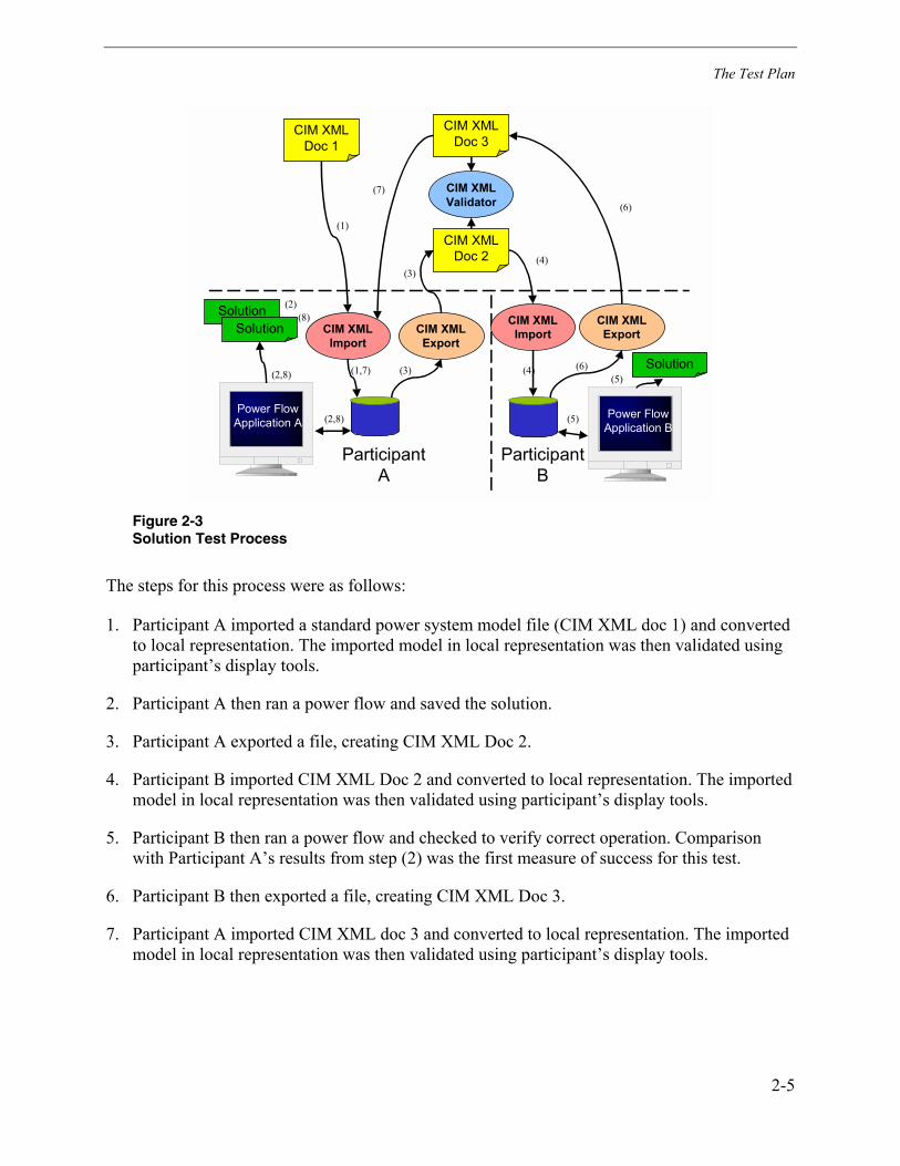
The Solution test was intended to verify the correct exchange and transformation of powersystem model files including generation and load through the execution of power flowapplications. Verification was accomplished by a comparison of solutions before and aftertransformation and model exchange, as illustrated in Figure 2-3.
The Test Plan
2-5
ParticipantA
ParticipantB
CIM XMLImport
CIM XMLDoc 1
Power FlowApplication A
CIM XMLImport
Power FlowApplication B
CIM XMLExport
CIM XMLDoc 2
CIM XMLValidator
CIM XMLExport
CIM XMLDoc 3
SolutionSolution
(1)
(5) (4) (6)
(3)
(3) (2,8)
(2,8)
(1,7)
(6)
(4)
(7)
(5)
Solution
(8) (2)
Figure 2-3Solution Test Process
The steps for this process were as follows:
1. Participant A imported a standard power system model file (CIM XML doc 1) and convertedto local representation. The imported model in local representation was then validated usingparticipant�s display tools.
2. Participant A then ran a power flow and saved the solution.
3. Participant A exported a file, creating CIM XML Doc 2.
4. Participant B imported CIM XML Doc 2 and converted to local representation. The importedmodel in local representation was then validated using participant�s display tools.
5. Participant B then ran a power flow and checked to verify correct operation. Comparisonwith Participant A�s results from step (2) was the first measure of success for this test.
6. Participant B then exported a file, creating CIM XML Doc 3.
7. Participant A imported CIM XML doc 3 and converted to local representation. The importedmodel in local representation was then validated using participant�s display tools.

The Test Plan
2-6
8. Participant A then ran a power flow and compared results with the solution obtained in step(2) to determine if the solutions matched within a reasonable margin, which was the secondmeasure of a successful test1.
The reason for a complete round trip is recognition that solutions generated by Power Flowapplications from different suppliers may be different and not readily comparable.
Any of the sample model files could be used for this test. The following instance data wasprovided for each Sample Model to be used in this test as part of the CIM XML documentcontents:
• Generation values
• Load values
• Transformer settings
• Generator voltage control values
• Device states
• MVAr values for shunt Compensators
Test Configuration
The details of the specific files used at the beginning of the testing period are specified inAppendix B. This appendix contains file names for the CIM ROSE model, the RDF schema,RDF syntax definition, and sample model files. As testing progressed and problems werediscovered and resolved, updates were generated to some of these files.
1 The solutions of multiple runs of a power flow after exporting and re-importing from anotherparticipant were expected to result in consistent solutions with reasonable differences that resultfrom model translation to local representation.

3-1
3 TEST RESULTS
This section presents the results of the interoperability tests. First, the individual tests that wereperformed and scored are summarized below. This is followed by the test matrices with scoresshown for each test. For details on each test step, including setup required and step-by-stepprocedures, see the Test Procedures document (Reference 2).
Table 3-1Description of Tests Performed
CIM 09b Validation
1 Basic Import
1.1 Participant A import small model and demonstrate import was done correctly
1.2 Participant A import 40 bus model and demonstrate import was done correctly
1.3 Participant A import 60 bus model and demonstrate import was done correctly
1.4 Participant A import 100 model and demonstrate import was done correctly
2 Basic Export
2.1 Participant A export small model and run validator
2.2 Participant A export 40 bus model and run validator
2.3 Participant A export 60 bus model and run validator
2.4 Participant A export 100 bus model and run validator
3 Interoperation - Participant B import of Participant A exported CIM XML file.
Scalability Test
4 Basic Import – Participant A import Duke large scale model
5 Basic Export – Participant A export Duke large scale model
6 Interoperation - Participant B import of Participant A exported Duke large scalemodel CIM XML file.
Solution Test
7 Import Sample Model (Doc-1)

Test Results
3-2
8 Run Power Flow application and save solution (Sol-1)
9 Export sample model (Doc-2)
10 Import previously exported sample model file (Doc-2) from anotherparticipant
11 Run Power Flow application and save solution (Sol-2)
12 Compare Sol-1 with Sol-2
13 Export sample model (Doc-3)
14 Import Doc-3 from another participant
15 Run Power Flow application and save solution (Sol-3)
16 Compare Power Flow Sol-1 with Sol-3
Summary of Test Results
The following sections report the highlights of the testing.
CIM 09b Validation
Basic Import and Export
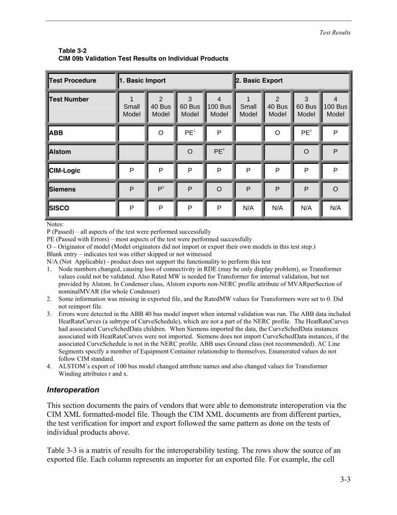
Table 3-2 shows the results of the tests on the individual products to determine compliance withthe CIM version 09b XML/RDF standards. The primary objective of this test was to successfullyimport and export one of the sample model files to show compliance, although all sample modelfiles were available for further demonstration of interoperability. All of the participants were ableto pass this test. Highlights of the tests are as follows:
• All participants were able to successfully import at least one model file correctly convertingfrom the CIM XML format to their internal proprietary format. Thus all participants wereable to demonstrate compliance with the latest Version 9b of the CIM on import.
• CIM-Logic, Siemens, and SISCO successfully imported all the sample models available.
• All of the participants able to export a model file did export at least one file successfully, thusdemonstrating compliance with version 9b of the CIM for export.
• CIM-Logic and Siemens exported all sample model files successfully.
Test Results
3-3
Table 3-2CIM 09b Validation Test Results on Individual Products
Test Procedure 1. Basic Import 2. Basic Export
Test Number 1SmallModel
240 BusModel
360 BusModel
4100 BusModel
1SmallModel
240 BusModel
360 BusModel
4100 BusModel
ABB O PE1 P O PE2 P
Alstom O PE4 O P
CIM-Logic P P P P P P P P
Siemens P P3 P O P P P O
SISCO P P P P N/A N/A N/A N/A
Notes:P (Passed) � all aspects of the test were performed successfullyPE (Passed with Errors) � most aspects of the test were performed successfullyO � Originator of model (Model originators did not import or export their own models in this test step.)Blank entry � indicates test was either skipped or not witnessedN/A (Not Applicable) - product does not support the functionality to perform this test1. Node numbers changed, causing loss of connectivity in RDE (may be only display problem), so Transformer
values could not be validated. Also Rated MW is needed for Transformer for internal validation, but notprovided by Alstom. In Condenser class, Alstom exports non-NERC profile attribute of MVARperSection ofnominalMVAR (for whole Condenser)
2. Some information was missing in exported file, and the RatedMW values for Transformers were set to 0. Didnot reimport file.
3. Errors were detected in the ABB 40 bus model import when internal validation was run. The ABB data includedHeatRateCurves (a subtype of CurveSchedule), which are not a part of the NERC profile. The HeatRateCurveshad associated CurveSchedData children. When Siemens imported the data, the CurveSchedData instancesassociated with HeatRateCurves were not imported. Siemens does not import CurveSchedData instances, if theassociated CurveSchedule is not in the NERC profile. ABB uses Ground class (not recommended). AC LineSegments specify a member of Equipment Container relationship to themselves. Enumerated values do notfollow CIM standard.
4. ALSTOM�s export of 100 bus model changed attribute names and also changed values for TransformerWinding attributes r and x.
Interoperation
This section documents the pairs of vendors that were able to demonstrate interoperation via theCIM XML formatted-model file. Though the CIM XML documents are from different parties,the test verification for import and export followed the same pattern as done on the tests ofindividual products above.
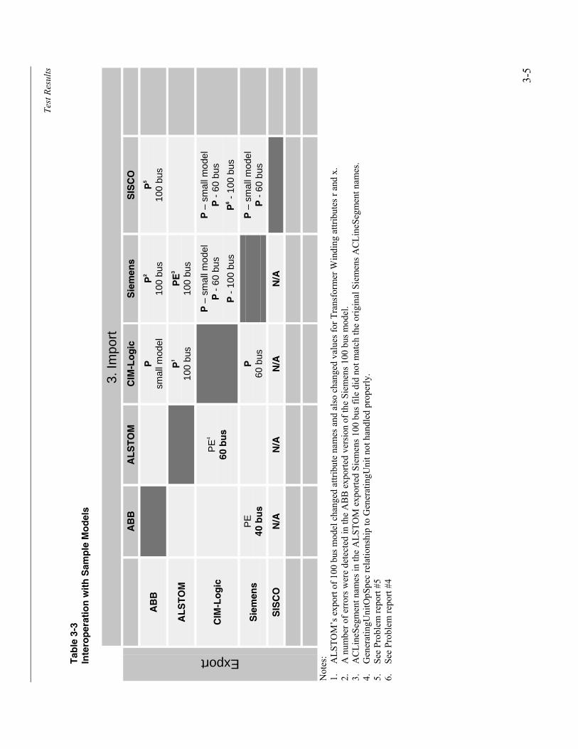
Table 3-3 is a matrix of results for the interoperability testing. The rows show the source of anexported file. Each column represents an importer for an exported file. For example, the cell

Test Results
3-4
(row ALSTOM, column CIM-Logic) indicates the result of the interoperability test of CIM-Logic importing CIM XML documents exported by ALSTOM ESCA.
The entries in each cell should be interpreted as follows:
• P � Pass. Indicates a successful import of another participant�s exported file. The specificsample model file imported is indicated.
• PE (Passed with Errors) � most aspects of the test were performed successfully
• N/A - Product does not have export functionality
• Blank (no entry) � indicates test was skipped, not witnessed, or an exported model file wasnot available for import.
All participants with functionality to export a file did so successfully and then made that fileavailable on the LAN server for other participants to import. Therefore, a blank entry in acolumn indicates that the participant whose name is at the heading for that column did notdemonstrate an import of that file.
These tests demonstrate true interoperability by exchanging CIM XML documents produced bydifferent participants. A Pass indicates that a pair of vendors successfully demonstrated theexchange of a power system model file using the CIM XML format. The specific model fileexchanged is also identified.
Highlights of the tests are as follows:
• 16 pairs of vendors were able to interoperate successfully by exchanging at least one samplemodel file.
• Two vendors successfully imported three files exported by other vendors.
Test
Res
ults
3-5
Tab
le 3
-3In
tero
per
atio
n w
ith
Sam
ple
Mo
del
s
3. Im
port
AB
BA
LS
TO
MC
IM-L
og
icS
iem
ens
SIS
CO
AB
BP
smal
l mod
elP
2
100
bus
P5
100
bus
AL
ST
OM
P1
100
bus
PE
3
100
bus
CIM
-Lo
gic
PE
4
60 b
us
P –
sm
all m
odel
P -
60
bus
P -
100
bus
P –
sm
all m
odel
P -
60
bus
P6 -
100
bus
Sie
men
sP
E40
bu
sP
60 b
usP
– s
mal
l mod
elP
- 6
0 bu
s
SIS
CO
N/A
N/A
N/A
N/A
Export
Not
es:
1.
ALS
TOM
�s e
xpor
t of 1
00 b
us m
odel
cha
nged
attr
ibut
e na
mes
and
als
o ch
ange
d va
lues
for T
rans
form
er W
indi
ng a
ttrib
utes
r an
d x.
2.
A n
umbe
r of e
rror
s wer
e de
tect
ed in
the
AB
B e
xpor
ted
vers
ion
of th
e Si
emen
s 100
bus
mod
el.
3.
AC
Line
Segm
ent n
ames
in th
e A
LSTO
M e
xpor
ted
Siem
ens 1
00 b
us fi
le d
id n
ot m
atch
the
orig
inal
Sie
men
s AC
Line
Segm
ent n
ames
.4.
G
ener
atin
gUni
tOpS
pec
rela
tions
hip
to G
ener
atin
gUni
t not
han
dled
pro
perly
.5.
Se
e Pr
oble
m re
port
#56.
Se
e Pr
oble
m re
port
#4

Test Results
3-6
Scalability
This test used the same test procedures as used for the CIM 09b Validation test, except thatparticipants imported and exported the Duke Energy large system model.
Due to the size of the model and the time required to import and validate, it was suggested thatparticipants come prepared with a Duke Energy CIM XML document that they had already beencreated (exported) ahead of time. That meant that they had already imported and validated themodel off-site as well as exported it for use by other participants, hopefully prior to the on-sitetesting. To get credit for a successful import and internal validation, participants had to bring adatabase and display capability to permit an observer to check on-site that the model wasimported correctly. The exported model was validated on-site as well using the XML Validationtool.
Due to the size of the model and the time required to import and validate, it is not expected thatall of the matrix of possible interactions will be tested. A participant was instructed to chooseone or two of the other participant�s large model exported documents to import until success isachieved. Then, as time permits, additional exported models could be attempted.
Duke Model Import and Export
Table 3-4 shows the results of the on the individual products to import and export the large scaleDuke Energy model. The XML Validator tool initially experienced problems when applied tothis large scale model, but was revised to eliminate the scaling problems. Unfortunately, therevised version was not available until later in the tests, so not all participants were able todemonstrate validation with the tool.
Highlights of the test are as follows:
• All of the participants were able to successfully import the Duke Energy model
• All participants (except for SISCO, which does not have an export capability) were able tosuccessfully export the Duke Energy model .

Test Results
3-7
Table 3-4Scalability Test on Individual Products
Test Procedure 4. Duke Model Import 5. Duke Model Export
ABB PE1 PE1
Alstom P3 P
CIM-Logic P P2
Siemens P P2
SISCO P N/A
Notes:P (Passed) � all aspects of the test were performed successfullyPE (Passed with Errors) � most aspects of the test were performed successfullyN/A (Not Applicable) - product does not support the functionality to perform this test1. Rated MVA not provided in model, so RDE tool calculates r, x = 0 for Transformer Winding, which
prevents model use and causes errors in exported model file.2. Validator not run on exported file.3. Internal validation reported some errors that were not able to be properly analyzed during the test period.
Interoperation with Duke Model
This section documents the pairs of vendors that were able to demonstrate interoperation via theCIM XML-formatted Duke Energy model file. Though the CIM XML documents are fromdifferent parties, the test verification for import and export followed the same pattern as done onthe tests of individual products above.
Table 3-5 is a matrix of results for the interoperability testing. The rows show the source of anexported file. Each column represents an importer for an exported file. For example, the cell(row ALSTOM, column CIM-Logic) indicates the result of the interoperability test of CIM-Logic importing CIM XML documents exported by ALSTOM ESCA.
The entries in each cell should be interpreted as follows:
• P � Pass. Indicates a successful import of another participant�s exported file. The specificsample model file imported is indicated.
• PE (Passed with Errors) � most aspects of the test were performed successfully
• N/A - Product does not have export functionality
• Blank (no entry) � The column participant did not demonstrate an import of the file exportedby the row participant.
All participants with functionality to export a file did so successfully and then made that fileavailable on the LAN server for other participants to import. Therefore, a blank entry in acolumn indicates that the participant whose name is at the heading for that column did notdemonstrate an import of that file.

Test Results
3-8
These tests demonstrate true interoperability by exchanging CIM XML documents produced bydifferent participants. A Pass indicates that a pair of vendors successfully demonstrated theexchange of a power system model file using the CIM XML format. The specific model fileexchanged is also identified.
Highlights of the tests are as follows:
• Ten pairs of vendors were able to interoperate successfully by exchanging the Duke Energymodel file, thus demonstrating scalability of their products to handle larger model files.However, import times varied from 20 minutes to import directly to an Oracle database toseveral hours for import into an engineering/modeling tool capable of displaying one-linediagrams.Table 3-5Interoperation with Duke Energy Model
Import
ABB ALSTOM CIM-Logic Siemens SISCO
ABB P P
ALSTOM P P P P
CIM-Logic P P
Siemens P P
SISCO N/A N/A N/A N/A
Exp
ort
Solution Test
Power Flow Applications produce MW and MVar flows for each line in the model. The MW &MVar flows are a direct function of the voltage difference between the two ends of a line and theresistance of the line. They serve as a check on the transfer of the characteristics of a line(topological connectivity and impedance), but are direct derivatives of the voltage.
As part of the solution, each Power Flow Application was asked to produce a table of bus voltageand voltage angle readings for each bus in the model. To evaluate power flow solutions, thetables produced by two different executions of a Participant�s Power Flow Application werecompared.
If the models used for both executions are identical, then the solutions should be very close,although identical solutions are not expected due to the small effects of conversions between
Test Results
3-9
participants. If the models are identical, but different Participant�s applications are used, againthe table values are not expected to be identical, but should be consistent and within a reasonablerange of each other.
It should be kept in mind that the purpose of the test was not to evaluate different Participant�sPower Flow Applications, but rather to ensure that the contents and format of the CIM XMLdocuments exchanged are sufficient to permit each Participant�s product to converge on asolution.
Table 3-6 shows the results of each of the steps in the Solution test. Highlights of the Solutiontest are as follows:
• Two of the three participants with power flow applications successfully completed all thesignificant solution tests (only an export step was not done for lack of time). ABB chose notto attempt the Solution test.
• Alstom and Siemens were able to successfully import a sample model file, run their PowerFlow application (solution 1), and export.
• Alstom and Siemens were able to import a model file previously exported by anotherparticipant and successfully run their Power Flow application (solution 2), thusdemonstrating that the contents of the CIM XML document are adequate for running PowerFlows.
• Siemens was able to compare two sets of solutions (1 and 2, 1 and 3). In one case, thesolutions were almost identical, in the other there was a close match for MW flows, butdifferences in Mvar flows, bus voltage, and angle were significant.
• Alstom was able to compare solutions 1 and 3. Solutions were almost identical. Alstom wasnot able to compare solutions 1 and 2, since different sample models were used for each.
• Bottom line: The contents and format of the power system model files exchanged with theCIM XML file representation are adequate for running power flow applications, and the nosignificant data was lost during data transformations to/from the CIM XML format.

Test
Res
ults
3-10
Tab
le 3
-6S
olu
tio
n T
est
Res
ult
s
Tes
t N
um
ber
7Im
po
rtd
oc-
1
8R
un
PF
sol-
1
9E
xpo
rtd
oc-
2
10Im
po
rtd
oc-
2
11R
un
PF
sol-
2
12C
om
par
eso
l-1,
so
l-2
13E
xpo
rtd
oc-
3
14Im
po
rt
do
c-3
15R
un
PF
sol-
3
16C
om
par
eso
l-1,
so
l-3
AB
B
Als
tom
P10
0 b
us
P10
0 b
us
P10
0 b
us
P60
bu
sfr
om
CIM
-L
og
ic
P60
bu
sfr
om
CIM
-L
og
ic
N/A
P10
0 b
us
fro
mA
lsto
m v
ia C
IML
og
ic
PP
1
CIM
-Lo
gic
N/A
N/A
N/A
N/A
N/A
N/A
N/A
N/A
N/A
N/A
Sie
men
sP
60 b
us
P60
bu
sP
60 b
us
P60
bu
sfr
om
AB
B
P60
bu
sfr
om
AB
B
P1
P60
bu
s fr
om
Sie
men
s vi
aC
IM-L
og
ic
PP
2
SIS
CO
N/A
N/A
N/A
N/A
N/A
N/A
N/A
N/A
N/A
N/A
1.
Ver
y cl
ose
mat
ch o
f sol
utio
ns (t
rans
form
er a
nd li
ne fl
ows i
dent
ical
, slig
ht d
iffer
ence
s in
bus v
olta
ge a
nd a
ngle
2.
MW
clo
se m
atch
, but
diff
eren
ces i
n M
var f
low
s, bu
s vol
tage
, and
ang
le w
ere
sign
ifica
nt

Test Results
3-11
Summary of Issues Identified
Another output of the testing effort was the identification of issues that affect interoperability,either in the CIM documents themselves, in the sample model files, or in the test procedures.Every attempt was made to resolve issues during testing so that a common resolution could beadopted and implemented by each participant, followed by a retest.
The following is a summary of the issues that were identified organized by category and howthey will be resolved. The detailed problem reports with resolutions and status are contained inAppendix C:
• CIM issues for the most part require resolution by the IEC WG13 responsible for the CIMstandard, so resolutions were not reached and these are open issues.
• NERC CPSM profile issues are suggestions to the DEWG for changes to improveinteroperability or for adopting conventions about how to constrain the flexibility in the CIMmodel for consistent use in exchanging power system models.
• Tool issues were resolved.
• Sample model file problems for the most part were corrected and revised on the spot,uploaded to the LAN server, and used for retest. However, in some cases, the suppliers of themodels will be asked to make revisions before the next set of tests.
• Product issues are up to the participants to resolve.


4-1
4 FUTURE INTEROPERABILITY TESTS
Plans for future interoperability tests need to be defined. However, it is expected that they willinclude the following:
1. Opportunities for more participants to complete the tests used for this second interoperabilitytest.
2. Duke Energy model with Powerflow Applications: Run Powerflow applications using a largescale model.
3. WAPA model with Powerflow Applications: Use the WAPA planning model afterconversion to an operational model. Participants can run their Power Flow applications anddemonstrate other applications (e.g., OPF and State Estimator), as available. This will testlarger models with loads.
4. Incremental updates: Once a protocol has been specified to permit methods to be included inmessage exchanges and a process to handle incremental model updates is defined, thentesting of this incremental update capability will be needed.
5. Additional applications: Run additional applications of exchanged model files, such as StateEstimator and Optimal Power Flow.
6. Exchange of solved power flow solutions: This is an existing need that will be tested once asolution is defined.
Items 1-3 are important to NERC for the September 2001 deadline to exchange models usingCIM XML. Items 4-6 are for future testing after this date.


A-1
A APPENDIX: PARTICIPANT PRODUCT DESCRIPTIONS
This appendix contains descriptions of the different products used for the interoperability tests.The product descriptions were provided by the individual participants.
ABB Data Engineering Tool (RDE)
The test procedures related to CIM XML model exchange will be performed against the ABBdata engineering tool (RDE).
The CIM schema has been implemented in an Oracle database. This CIM Oracle database will beused for both import and export processes.
We will be using ABB�s data engineering tool (RDE). This is also an Oracle database tool thatallows view of the data as well as changing of the data. The runtime database system ispopulated by the RDE either as a full population or as an incremental population.
During the import process, data from the CIM database will be imported to the RDE. During theexport process, data from RDE will be exported to the CIM database.
DataEngineering
(RDE)
CIMOracle
DatabaseNetwork Models
in XML/RDFformat
Import
Export
Figure A-1ABB's Data Engineering Tool (RDE)
ALSTOM ESCA eTerra-Modeler and Study Powerflow
The test procedures related to CIM XML model exchange are to be performed against theALSTOM eTerra-Modeler product (also referred to as the Modeler) and the Study Powerflowapplication.
Appendix: Participant Product Descriptions
A-2
eTerra Modeler
The Modeler is a power systems operations modeling tool for initializing EMS applications withthe information they need for real-time operations. The tool is used to generate the powersystem models and maintain them. Import and export facilities are provided for bulk data importand export while a tailored user interface is used for manual additions, edits, and deletions ofinformation as well as model browsing.
The tool runs in a Windows 2000 environment. Though the design supports a distributedconfiguration, all components will be located on a single NT platform for the purposes of thisinteroperability test. Model validation software is included which verifies the integrity of themodel and prepares information for use by operational applications such as the Study Powerflow.
Study Powerflow
The Study Powerflow (aka Powerflow) is one of a suite of transmission network analysisapplications that also includes State Estimation, Contingency Analysis, OPF, etc. Theseapplications are designed for use by operators in an EMS environment. The Powerflow isinitialized with information from the real-time system, other network analysis applications, or theModeler. The last initialization option is what is used in this interoperability test.
The Powerflow is configurable to use several solution techniques and has many options withrespect to how slack generation and other solution variables are handled. A distributed slackscheme is used for these tests.
Modeling Conventions
For this interoperability test, the following conversions between the Modeler informationrepresentation and the CIM XML representation are required:
• CIM Bays and VoltageLevels are represented as Equipment Groups in the Modeler.
• CIM BusSections are represented as nodes.
• CIM Condensers are a type of synchronous machine.
• All CIM switch types are modeled as switches.
• Grounds are not modeled as separate objects.
• Single terminal devices are interpreted as shunts.
CIM-Logic JCIM
The test procedures related to CIM XML model exchange are proposed to be performed againstthe CIM-Logic JCIM product.
Appendix: Participant Product Descriptions
A-3
JCIM is a stand alone data maintenance tool and also an integrated J2EE developmentenvironment. JCIM provides a flexible set of software tools based on a stable set of classesdriven by a model specified in UML. These classes can access data from multiple data sourcesand make the data available to users with standard desktop browsers. Data can be imported to orexported from an Oracle8i relational database from CIM RDF format.
Siemens Information Model Manager
The test procedures related to CIM XML model exchange are proposed to be performed againstthe Siemens Information Model Manager and Optimal Power Flow products.
The Siemens Information Model Manager (IMM) is a component of the PowerCC product line.It provides the means to maintain power system model data for the configuration of EMS/DMSapplications, SCADA and the communication to RTU�s, and ICCP. For the interoperability testonly a subset of the data model is used.
The IMM provides import/export of bulk model data as well as a user interface to manually viewand edit model data. The import/export format is compliant to the CIM/XML informationexchange format. The IMM uses a repository driven by a schema compliant with the NERCCPSM profile of the CIM u09b.
The user interface provides a hierarchical view of the instances imported or manually edited. Itallows creation of new instances, as well as modification of exiting ones. Instance data can bedeleted selectively. Child instances in the hierarchy are recursively deleted in the same operation.
The import/export function of the IMM records errors in a log for further analysis while runningan import. Import translates the RDF/XML document into the internal structure of the IMMrepository. Export retrieves all data for a selected instance and exports it according to the definedprofile.
Changes and extension of the current model data can be prepared independent of the currentactive model data in a session. An activation process applies the changes to the current modeldata and applications get notified about those changes. This part of the functionality is not usedin the test environment.
The Optimal Power Flow is one of the functions within Siemens set of study and real-timeNetwork Applications. It can be executed in dispatcher�s mode or optimization mode based on avariety of optimization criteria. For the purposes of this test, dispatcher�s mode is used.
The IMM and Network Applications uses a Window 2000 platform. Although it can beconfigured for a multiple server environment, the complete systems runs on a laptop for theinteroperability test.

Appendix: Participant Product Descriptions
A-4
SISCO Utility Integration Bus
The test procedures related to CIM XML model exchange are to be performed against the CIMRDF import utility provided by SISCO as part of the Utility Integration Bus (UIB) product.
The UIB is a message broker based enterprise application integration product created to meet theunique needs of utilities. The UIB allows users to publish and subscribe to messages by selectingall or parts of the CIM schema/operational model as well as determine what parts of theschema/operational model are currently being published on the bus by UIB components.
The CIM test files are imported through the CIM RDF import utility provided by SISCO as partof the UIB product, as shown in the diagram below. The import utility stores the CIM RDFinformation in a meta-data repository supplied with the UIB product. Once the CIM schemadefinition and operational information files have been imported, UIB applications can browsethis information via a Data Access Facility (DAF) interface.
An XML IOP application developed for these interoperability tests will be used to validate theCIM import capability of the UIB only, as shown below. There is no export capability for themodel data, so those portions of the test procedure dealing with exporting of files will beskipped.
CIM 0.9Operational
UIB
CIM
RD
F Import U
tility
CIM 0.9Schema
SQLServer
UIB Store
DAF Server
UIB
DAF Client
XML IOPTest Application
XML IOPReport
Figure A-2SISCO Utility Integration Bus

Appendix: Participant Product Descriptions
A-5
This import capability will be demonstrated through the importing of two (2) CIM files (the 0.9bschema definition and the vendor supplied operational information CIM file). These files areimported through the CIM RDF import utility, provided by SISCO as part of the UIB product.The import utility will translate the CIM RDF information into a SISCO proprietary meta-datarepository supplied with the UIB product. The repository is known as the UIB Store and shalluse SQL Server as the database that stores the repository information. The UIB Store containsboth schema and operational information.
SISCO supplies the UIB Store is with a UIB based Data Access Facility (DAF) wrapper thatallows standardized access to the schema and operational information over the UIB viamessages. A test application has been written to produce a text report, via DAF, that reflects theoperational data imported stored within the UIB Store.
The UIB components being tested do not validate nor export the CIM information in regards topower system network information. Nor do the components make this information availableexcept through the DAF interfaces provided by the SISCO UIB product.
The software to be tested by SISCO consists of the following:Table A-1UIB Toolkit Version 1.0
Message Broker IBM MQSeries V5.1
UIB Store Repository SQL Server 7.0
DAF Client Interface SISCO Version 1.0
Operating System Windows NT 4.0/ Service Pack 6
All software components are installed and located on a single Toshiba Satellite Laptop. Thelaptop resources are: 4G hard drive, 128MB of RAM, 366 MHz Intel Celeron.
XML Authority will be used to validate XML files.


B-1
B APPENDIX: TEST CONFIGURATION DATA
Test Procedures
The test procedure for this series of tests was CIM XML Interoperability Test 2, Test Plan andProcedures, Revision 3, April 28, 2001 contained in the following file:
• Test procedures: cimxml test 2 plan rev3.DOC
CIM Baseline Version for Testing
The version of the CIM used for these tests was 09b. Specifically, the CIM RDF Schema versionof this file was used. Any file generated or imported was required to conform to this RDFSchema, although only the classes , attributes, and relations defined in the NERC CPSM profileneeded to be included.
The files used for the CIM UML and RDF schema were as follows:
• CIM ROSE UML file: cimu09b_010422.mdl
• CIM RDF Schema file: cimu09b_010422.rdf
RDF Syntax
The RDF syntax approved for these tests is the Reduced RDF (RRDF) Syntax defined by ArnolddeVos. Files produced may contain syntax definitions beyond the RRDF Syntax, but only theRRDF Syntax was used to completely express the power system model in the file produced fortesting. Participants reading files were expected to properly interpret the RRDF Syntaxdefinitions contained therein but were not required to interpret and use any definitions beyondthe RRDF Syntax.
The file used for the RDF syntax definition was as follows:
• CIM XML syntax definition: Simplified RDF Syntax 6.pdf
Test Files
Each participant was requested to post a sample model file that they have produced using theReduced RDF Syntax approved for these tests. Each such sample file was accompanied by a one-line schematic diagram illustrating at least parts of the power system model defined in the file.
Appendix: Test Configuration Data
B-2
The test files provided for the sample models were as follows (final updates were made duringthe test):
• PsyCor small model: SmallModel_010424.zip
• ABB 40 bus model: ABB40bus_04-27-01.xml
• ALSTOM ESCA 60 bus model: esca60.cim9b.04_26_2001.zip
• Siemens 100 bus model: siemens100_RDF_9b_04-20-2001.zip
The Duke Energy model used is available only on a restricted basis.
Tools
The tools used for the interoperability testing were as follows:
• Validation tools: CIMValidate-2001-05-01.zip
• UML to RDF Converter tool: Xpetal-2000-12-16.zip
File Transfer
For sharing or transferring files between participant�s systems was accomplished using a sharedfile server (provided by PsyCor) and connected to by all participants through a LAN switch(provided by ALSTOM ESCA).

C-1
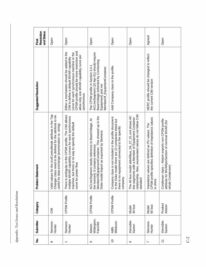
C APPENDIX: TEST ISSUES AND RESOLUTIONS
This appendix contains a list of the issues identified during the CIM XML interoperability testingorganized by category. The status of the resolutions reached during the testing period are alsoreported. The open issues will be addressed within the CCAPI Task Force and IEC WorkingGroup 13.
The issue categories include the following:
• CIM � issues dealing with the CIM model
• NERC CPSM Profile � issues with the format or content of the NERC CPSM profiledefinition of classes, attributes, and associations to be included in the sample model files, orthe way the profile definitions are handled in UML or XML/RDF
• Products in Test � issues concerned with the specific product under test
• Tools � issues with the CIM XML validator tool
Appe
ndix
: Tes
t Iss
ues a
nd R
esol
utio
ns
C-2
No.
Sub
mitt
erC
ateg
ory
Pro
blem
Sta
tem
ent
Sug
gest
ed R
esol
utio
nFi
nal
Res
olut
ion
and
Sta
tus
8S
iem
ens-
Hun
ter
CIM
Val
id v
alue
s fo
r th
e tc
ulC
ontr
olM
ode
attr
ibut
e in
the
Tap
Cha
nger
cla
ss n
eed
to b
e de
fined
for
the
attr
ibut
e to
be
usef
ul fo
r da
ta e
xcha
nge
(enu
mer
atio
n vs
. str
ing)
Ope
n
1S
iem
ens-
Hun
ter
CP
SM
Pro
file
The
re is
am
bigu
ity in
the
CP
SM
pro
file:
The
CIM
allo
ws
mul
tiple
MV
AR
cap
abili
ty c
urve
s fo
r ea
ch s
ynch
rono
usm
achi
ne, b
ut th
ere
is n
o w
ay to
spe
cify
the
defa
ult
curv
e fo
r po
wer
flow
Eith
er a
mec
hani
sm s
houl
d be
add
ed to
the
CIM
to d
efin
e a
defa
ult M
VA
R c
apab
ility
curv
e fo
r ea
ch s
ynch
rono
us m
achi
ne o
r th
eC
PS
M p
rofil
e sh
ould
be
mor
e re
stric
tive
and
allo
w o
nly
one
MV
AR
cap
abili
ty c
urve
per
sync
hron
ous
Ope
n
9A
lsto
m-
Wid
ergr
en,
Fai
rchi
ld
CP
SM
Pro
file
AC
Line
Seg
men
t nee
ds r
efer
ence
to B
aseV
olta
ge. A
tth
e m
omen
t, it
cont
ains
ref
eren
ceM
embe
rOfE
quip
men
tCon
tain
er. T
his
show
ed u
p in
the
Duk
e m
odel
impo
rt a
s ex
port
ed b
y S
iem
ens
The
CP
SM
pro
file
in S
ectio
n 3.
4.1
AC
Line
Seg
men
t (10
Apr
01)
sho
uld
requ
ireB
aseV
olta
ge (
inhe
rited
by
Con
duct
ing
Equ
ipm
ent)
and
not
Mem
berO
f_E
quip
men
tCon
tain
er.
Ope
n
10A
BB
-M
iloko
vic
CP
SM
Pro
file
Com
pany
cla
ss is
not
incl
uded
in th
e pr
ofile
doc
umen
t.In
the
Duk
e m
odel
ther
e ar
e 12
com
pani
es li
sted
but
ther
e is
no
equi
pmen
t con
nect
ed to
the
spec
ific
com
pany
.
Add
Com
pany
cla
ss to
the
prof
ile.
Ope
n
6X
tens
ible
-S
axto
nM
odel
40 b
usT
he 4
0 bu
s m
odel
abb
40bu
s_04
_27_
01.x
ml s
how
s A
Clin
e se
gmen
ts w
ith a
Mem
ber
of E
quip
men
t Con
tain
erre
latio
nshi
p. A
lso,
enu
mer
ated
val
ues
do n
ot fo
llow
CIM
stan
dard
Ope
n
7S
iem
ens-
Hun
ter
Mod
el60
bus
Impe
danc
e va
lues
are
def
ined
as
PU
val
ues.
The
CP
SM
pro
file
spec
ifies
def
initi
on o
f im
peda
nce
valu
esin
ohm
s
NE
RC
pro
file
shou
ld b
e ch
ange
d to
ref
lect
the
curr
ent C
IM v
ersi
onA
gree
d
11X
tens
ible
-S
axto
nP
rodu
ctA
lsto
mC
onde
nser
cla
ss –
Als
tom
exp
orts
non
-CP
SM
pro
file
attr
ibut
e fo
r M
VA
Rpe
rSec
tion
of n
omin
al M
VA
R (
for
who
le C
onde
nser
)
Ope
n
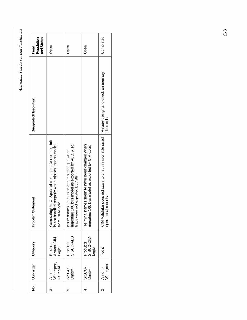
Appe
ndix
: Tes
t Iss
ues a
nd R
esol
utio
ns
C-3
No.
Sub
mitt
erC
ateg
ory
Pro
blem
Sta
tem
ent
Sug
gest
ed R
esol
utio
nFi
nal
Res
olut
ion
and
Sta
tus
3A
lsto
m-
Wid
ergr
en,
Fai
rchi
ld
Pro
duct
sA
lsto
m-C
IM-
Logi
c
Gen
erat
ingU
nitO
pSpe
c re
latio
nshi
p to
Gen
erat
ingU
nit
is n
ot h
andl
ed p
rope
rly w
hen
Als
tom
impo
rts
mod
elfr
om C
IM-L
ogic
Ope
n
5S
ISC
O-
Dm
itry
Pro
duct
sS
ISC
O-A
BB
Nod
e na
mes
see
m to
hav
e be
en c
hang
ed w
hen
impo
rtin
g 10
0 bu
s m
odel
as
expo
rted
by
AB
B. A
lso,
Bay
s w
ere
not e
xpor
ted
by A
BB
.
Ope
n
4S
ISC
O-
Dm
itry
Pro
duct
sS
ISC
O-C
IM-
Logi
c
Ter
min
al n
ames
see
m to
hav
e be
en c
hang
ed w
hen
impo
rtin
g 10
0 bu
s m
odel
as
expo
rted
by
CIM
-Log
icO
pen
2A
lsto
m-
Wid
ergr
enT
ools
CIM
Val
idat
or d
oes
not s
cale
to c
heck
rea
sona
ble
size
dop
erat
iona
l mod
els
Rev
iew
des
ign
and
chec
k on
mem
ory
dem
ands
Com
plet
ed


© 2001 Electric Power Research Institute (EPRI), Inc.All rightsreserved. Electric Power Research Institute and EPRI are registeredservice marks of the Electric Power Research Institute, Inc.EPRI. ELECTRIFY THE WORLD is a service mark of the ElectricPower Research Institute, Inc.
Printed on recycled paper in the United States of America
1006216
Target:
Grid Operations and Management
EPRI • 3412 Hillview Avenue, Palo Alto, California 94304 • PO Box 10412, Palo Alto, California 94303 • USA800.313.3774 • 650.855.2121 • [email protected] • www.epri.com
About EPRI
EPRI creates science and technology solutions for
the global energy and energy services industry. U.S.
electric utilities established the Electric Power
Research Institute in 1973 as a nonprofit research
consortium for the benefit of utility members, their
customers, and society. Now known simply as EPRI,
the company provides a wide range of innovative
products and services to more than 1000 energy-
related organizations in 40 countries. EPRI’s
multidisciplinary team of scientists and engineers
draws on a worldwide network of technical and
business expertise to help solve today’s toughest
energy and environmental problems.
EPRI. Electrify the World