report-- turbine-generator overspeed protection systems · turbine overspeed protection systems....
TRANSCRIPT

NUREG-1275Vol. 11
Operating Experience FeedbackReport-- Turbine-GeneratorOverspeed Protection Systems
Commercial Power Reactors
U.S. Nuclear Regulatory Commission
Office for Analysis and Evaluation of Operational Data
H.L Ornstein
AVAILABILITY NOTICE
Availability of Reference Materials Cited in NRC Publications
Most documents cited in NRC publications will be available from one of the following sources:
1. The NRC Public Document Room, 2120 L Street, NW., Lower Level, Washington, DC20555-0001
2. The Superintendent of Documents, U.S. Government Printing Office, P. 0. Box 37082,Washington, DC 20402-9328
3. The National Technical Information Service, Springfield, VA 22161-0002
Although the listing that follows represents the majority of documents cited in NRC publica-tions, It is not intended to be exhaustive.
Referenced documents available for inspection and copying for a fee from the NRC PublicDocument Room include NRC correspondence and internal NRC memoranda; NRC bulletins,circulars, information notices, inspection and investigation notices; licensee event reports;vendor reports and correspondence; Commission papers; and applicant and licensee docu-ments and correspondence.
The following documents in the NUREG series are available for purchase from the GovernmentPrinting Office: formal NRC staff and contractor reports, NRC-sponsored conference pro-ceedings, international agreement reports, grantee reports, and NRC booklets and bro-chures. Also available are regulatory guides, NRC regulations in the Code of Federal Regula-tions, and Nuclear Regulatory Commission Issuances.
Documents available from the National Technical Information Service include NUREG-seriesreports and technical reports prepared by other Federal agencies and reports prepared by theAtomic Energy Commission, forerunner agency to the Nuclear Regulatory Commission.
Documents available from public and special technical libraries include all open literatureitems, such as books, journal articles, and transactions. Federal Register notices, Federaland State legislation, and congressional reports can usually be obtained from these libraries.
Documents such as theses, dissertations, foreign reports and translations, and non-NRC con-ference proceedings are available for purchase from the organization sponsoring the publica-tion cited.
Single copies of NRC draft reports are available free, to the extent of supply, upon writtenrequest to the Office of Administration, Distribution and Mail Services Section, U.S. NuclearRegulatory Commission, Washington DC 20555-0001.
Copies of industry codes and standards used in a substantive manner in the NRC regulatoryprocess are maintained at the NRC Library, Two White Flint North, 11545 Rockville Pike, Rock-ville, MD 20852-2738, for use by the public. Codes and standards are usually copyrightedand may be purchased from the originating organization or, if they are American NationalStandards, from the American National Standards Institute, 1430 Broadway, New York, NY10018-3308.
NUREG-1275Vol. 11
Operating Experience FeedbackReport -- hrbine-GeneratorOverspeed Protection Systems
Commercial Power Reactors
I Mansc Ip C plted coe 1994ll
Manuscript Completed: October 1994Date Published: April 1995
H.L Ornstein
Safety Programs DivisionOffice for Analysis and Evaluation of Operational DataU.S. Nuclear Regulatory CommissionWashington, DC 20555-0001


ABSTRACT
This report presents the results of the U.S.Nuclear Regulatory Commission's Office forAnalysis and Evaluation of Operational Data(AEOD) review of operating experience ofmain turbine-generator overspeed and over-speed protection systems. It includes anindepth examination of the turbine overspeedevent which occurred on November 9, 1991, atthe Salem Unit 2 Nuclear Power Plant. It alsoprovides information concerning actions takenby other utilities and the turbine manufac-turers as a result of the Salem overspeedevent. AEOD's study reviewed operating pro-cedures and plant practices. It noted differ-ences between turbine manufacturer designsand recommendations for operations, main-tenance, and testing, and also identifiedsignificant variations in the manner thatindividual plants maintain and test theirturbine overspeed protection systems.
AEOD's study provides insight into theshortcomings in the design, operation, mainte-nance, testing, and human factors associatedwith turbine overspeed protection systems.
Operating experience indicates that thefrequency of turbine overspeed events is
higher than previously thought and that thebases for demonstrating compliance withNRC's General Design Criterion (GDC) 4,"Environmental and dynamic effects designbases," may be nonconservative with respectto the assumed frequency. GDC 4 requiresstructures, systems, and components impor-tant to safety to be appropriately protectedagainst dynamic effects that may result fromequipment failures and from events andconditions outside the nuclear power plant. Inaddition, compliance with GDC 4 may nothave considered fires and flooding associatedwith destructive turbine overspeed events.While turbine overspeed protection is onlypart of the criteria for meeting GDC 4 andcompliance may be accomplished in otherways, improvements in maintenance andtesting as noted in the study can enhance thereliability and operability of the main turbine-generators and their overspeed protectionsystems, and thus, raise confidence that theplants comply with ODC 4 by providingassurance that turbine overspeed eventinitiator frequency is consistent withassumptions.
iii NUREG-1275, Vol. 11

CONTENTS
Page
ABSTRA CT ........................................................................ iii
EXECUTIVE SUMMARY ........................................................... ix
FO REW O RD ...................................................................... xiii
AB BREVIATIONS .................................................................. xv
1 INTRODUCTION .............................................................. 1
2 HISTORICAL REVIEW ........................................................ 1
3 SALEM UNIT 2 OVERSPEED EVENT .......................................... 7
3.1 Description of the Event ..................................................... 73.2 Licensee's Response to the Event ............................................. 11
3.3 NRC Responses to the Event ................................................. 15
3.3.1 Immediate Actions .................................................... 15
3.3.2 Longer Tbrm Actions .................................................. 16
3.4 Root Causes of the Event .................................................... 16
3.4.1 Equipment Failure .................................................... 17
3.4.2 Inadequate Preventive Maintenance ..................................... 17
3.4.3 Inadequate Review and Feedback of Operational Experience .............. 17
3.4.4 Inadequate Surveillance Testing ......................................... 17
3.4.5 Human Factors Deficiencies in Front Standard Testing .................... 17
3.4.6 Test Lever ............................................................ 17
4 NUCLEAR INDUSTRY INITIATIVES AFTER THE SALEM UNIT 2OVERSPEED EVENT .......................................................... 18
4.1 Public Service Electric and Gas Company at Salem Units 1 and 2 ................ 18
4.2 Public Service Electric and Gas Company at Hope Creek ........................ 18
4.3 Westinghouse Power Generation Business Unit ................................. 19
4.4 General Electric Power Generation Division .................................... 21
4.5 Nuclear Power Plant Insurers ................................................. 22
4.6 W aterford U nit 3 ............................................................ 23
4.7 Comanche Peak Units 1 and 2 and Siemens/Allis Chalmers Tlrbines ............. 25
4.8 Specialized Turbine Overspeed Protection System Solenoid-Operated Valves ...... 26
5 RECENT OPERATING EXPERIENCE .......................................... 26
5.1 D iablo Canyon .............................................................. 26
5.1.1 Diablo Canyon Unit 1 Turbine Overspeed Event (September 12, 1992) ...... 26
5.1.2 Diablo Canyon Unit 2 Test Handle Trip (January 30, 1993) ................. 28
5.2 St. Lucie U nit 2 ............................................................. 30
5.2.1 St. Lucie Unit 2 Turbine Overspeed Event (April 21, 1992) ................. 30
V NUREG-1275, Vol. 11

CONTENTS (continued)
Page
5.2.2 St. Lucie Unit 2 Spurious Tirbine Trip During Solenoid-OperatedValve Testing (July 10, 1992) ............................................ 32
5.3 Big Rock Point .............................................................. 34
5.3.1 Big Rock Point Common-Mode Bypass Valve Failures .................... 345.3.2 Big Rock Point Repetitive Failures of the Turbine THp System ............. 345.3.3 Big Rock Point Long-Term Unavailability of Emergency
Governor Exerciser .................................................... 38
5.4 Palisades Common-Mode Failure of Six Steam Admission Valves ................. 385.5 Comanche Peak Unit 1 Inadequate Followup to Turbine Overspeed
Protection System Ibst Failure (May 16, 1992) .................................. 40
6 FINDINGS ..................................................................... 41
6.1 Complacency Tbward Turbine Overspeed ...................................... 416.2 Testing That Defeats Diversity ................................................ 416.3 Nonrevealing Surveillance Tbsting ............................................. 426.4 Inadequate Solenoid-Operated Valve Maintenance .............................. 426.5 Electrohydraulic Control System Fluid Quility ................................. 426.6 Electrohydraulic Control System Fluid Incompatibility .......................... 446.7 Human Factors Deficiencies .................................................. 456.8 Surveillance Tbsting Required By Plant Tbchnical Specifications .................. 45
7 CONCLUSIONS ................................................................ 45
7.1 M issiles .................................................................... 457.2 Fires, Explosions, Flooding ................................................... 467.3 Common-Mode Failure Precursors ............................................ 467.4 Industry Response to the Salem Unit 2 Overspeed Event ........................ 46
7.4.1 Overview ............................................................. 467.4.2 Turbine Manufacturer Actions .......................................... 477.4.3 Nuclear Utility Actions ................................................ 47
7.5 Trip Tbst Lever Human Factors Deficiency ..................................... 477.6 Overestimate of Design Life of Turbine Overspeed Protection System
Components ................................................................ 477.7 Nonconservative Probabilistic Assessments .................................... 487.8 Trends in Turbine Overspeed Protection System '&sting ......................... 487.9 Procedures for Shutting Off Steam Supply ..................................... 487.10 Sum m ary ................................................................... 48
8 REFERENCES ................................................................. 49
NUREG-1275, Vol. 11 Ai
CONTENTS (continued)
APPENDICES
Page
A LIST OF PLANTS BY SUPPLIER-REACTOR, TURBINE, GENERATOR
B SUMMARY OF SERT REPORT RECOMMENDATIONS
C CUSTOMER ADVISORY LETTER 92-02, "OPERATION, MAINTENANCE,TESTING OF, AND SYSTEM ENHANCEMENTS TO TURBINE OVERSPEEDPROTECTION SYSTEM"
D AVAILABILITY IMPROVEMENT BULLETIN 9301, "STEAM TURBINEOVERSPEED PROTECTION SYSTEM"
E HAMMER VALVE
F OPERATION & MAINTENANCE MEMO 108, "MAINTENANCE OFMAIN STOP VALVES & REHEAT STOP VALVES"
FIGURES
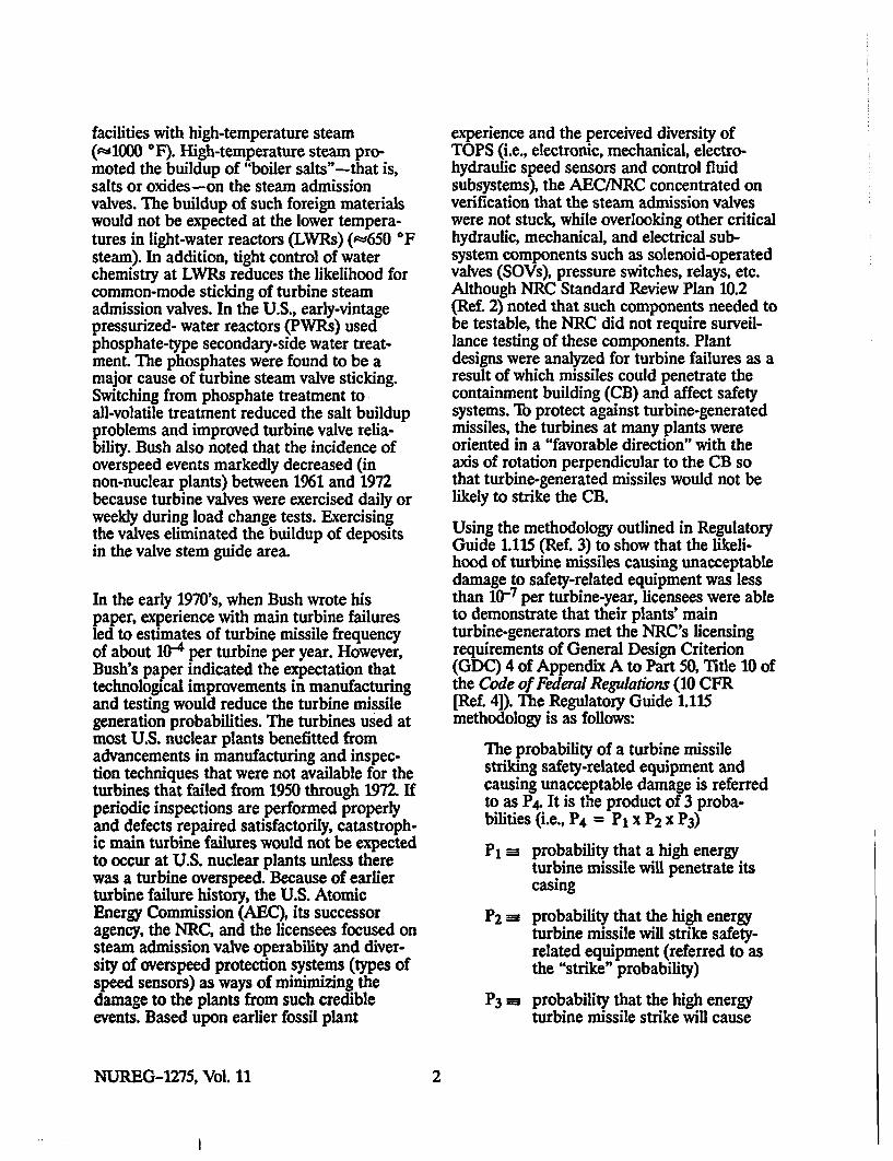
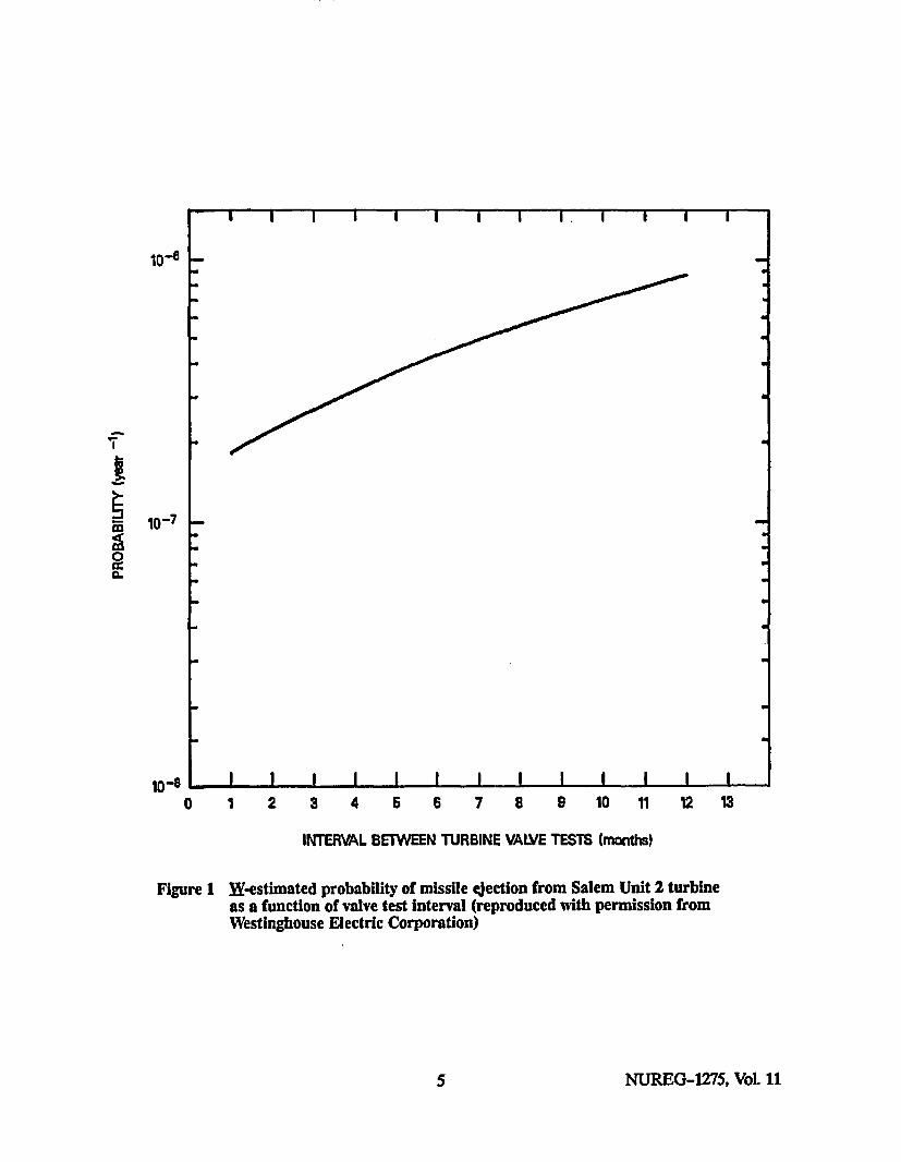
1 W-estimated probability of missile ejection from Salem Unit 2 turbine as a function
of valve test interval ............................................................. 5
2 Schematic of Salem turbine control system prior to November 1991 ................... 9
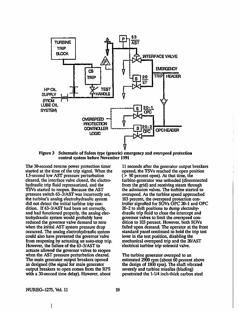
3 Schematic of Salem type (generic) emergency and overspeed protection control systemprior to November 1991 .................................................. ......... 10
4 Photograph: Salem Unit 2, showing holes in turbine casing .......................... 12
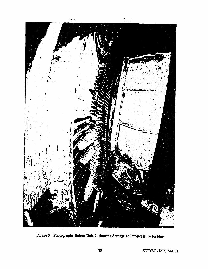
5 Photograph: Salem Unit 2, showing damage to low-pressure turbine .................. 13
6 Photograph: Salem Unit 2, showing condenser damage .............................. 14
7 Proposed improvement of Salem type (generic) emergency and overspeed protectioncontrol system .................................................................. 20
8 Waterford Unit 3 turbine control system ........................................... 24
9 Diablo Canyon turbine steam admission valves ..................................... 27
10 Photographs: Salem Unit 2 front standard panel (original and modified) .............. 29
11 St. Lucie block for testing EHC system SOVs independently ...................... 33
12 Big Rock Point-Original hand-trip solenoid valve............... .............. 37
13 Big Rock Point-Replacement hand-trip solenoid valve .............................. 39
14 Cross-sectional drawing of Parker Hannifin SOV MRFN 16MX 0834 ................. 43
vii NUREG-1275, Vol. 11
CONTENTS (continued)
TABLES
Page
1 Tbrbine system reliability criteria ................................................. 4
2 U.S. nuclear plant turbine overspeed events ........................................ 6
3 Precursors to the Salem Unit 2 overspeed event ..................................... 8
4 Major modifications made at Salem Units 1 and 2 .................................. 18
5 Turbine overspeed protection system enhancements made at Hope Creek .............. 19
6 Big Rock Point failure to trip history before 1992 ................................... 35
NUREG-1275, Vol. 11 viii"
EXECUTIVE SUMMARY
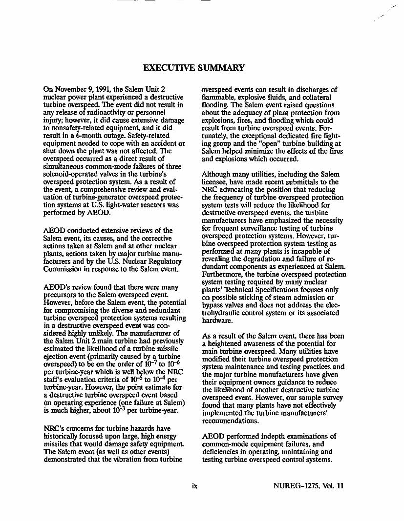
On November 9, 1991, the Salem Unit 2nuclear power plant experienced a destructiveturbine overspeed. The event did not result inany release of radioactivity or personnelinjury; however, it did cause extensive damageto nonsafety-related equipment, and it didresult in a 6-month outage. Safety-relatedequipment needed to cope with an accident orshut down the plant was not affected. Theoverspeed occurred as a direct result ofsimultaneous common-mode failures of threesolenoid-operated valves in the turbine'soverspeed protection system. As a result ofthe event, a comprehensive review and eval-uation of turbine-generator overspeed protec-tion systems at U.S. light-water reactors wasperformed by AEOD.
AEOD conducted extensive reviews of theSalem event, its causes, and the correctiveactions taken at Salem and at other nuclearplants, actions taken by major turbine manu-facturers and by the U.S. Nuclear RegulatoryCommission in response to the Salem event.
AEOD's review found that there were manyprecursors to the Salem overspeed event.However, before the Salem event, the potentialfor compromising the diverse and redundantturbine overspeed protection systems resultingin a destructive overspeed event was con-sidered highly unlikely. The manufacturer ofthe Salem Unit 2 main turbine had previouslyestimated the likelihood of a turbine missileejection event (primarily caused by a turbineoverspeed) to be on the order of 1O"7 to 10-6per turbine-year which is well below the NRCstaff's evaluation criteria of 10-5 to 10-4 perturbine-year. However, the point estimate fora destructive turbine overspeed event basedon operating experience (one failure at Salem)is much higher, about 10- per turbine-year.
NRC's concerns for turbine hazards havehistorically focused upon large, high energymissiles that would damage safety equipment.The Salem event (as well as other events)demonstrated that the vibration from turbine
overspeed events can result in discharges offlammable, explosive fluids, and collateralflooding. The Salem event raised questionsabout the adequacy of plant protection fromexplosions, fires, and flooding which couldresult from turbine overspeed events. For-tunately, the exceptional dedicated fire fight-ing group and the "open" turbine building atSalem helped minimize the effects of the firesand explosions which occurred.
Although many utilities, including the Salemlicensee, have made recent submittals to theNRC advocating the position that reducingthe frequency of turbine overspeed protectionsystem tests will reduce the likelihood fordestructive overspeed events, the turbinemanufacturers have emphasized the necessityfor frequent surveillance testing of turbineoverspeed protection systems. However, tur-bine overspeed protection system testing asperformed at many plants is incapable ofrevealing the degradation and failure of re-dundant components as experienced at Salem.Furthermore, the turbine overspeed protectionsystem testing required by many nuclearplants' Technical Specifications focuses onlyon possible sticking of steam admission orbypass valves and does not address the elec-trohydraulic control system or its associatedhardware.
As a result of the Salem event, there has beena heightened awareness of the potential formain turbine overspeed. Many utilities havemodified their turbine overspeed protectionsystem maintenance and testing practices andthe major turbine manufacturers have giventheir equipment owners guidance to reducethe likelihood of another destructive turbineoverspeed event. However, our sample surveyfound that many plants have not effectivelyimplemented the turbine manufacturers'recommendations.
AEOD performed indepth examinations ofcommon-mode equipment failures, anddeficiencies in operating, maintaining andtesting turbine overspeed control systems.
ix NUREG-1275, Vol. 11
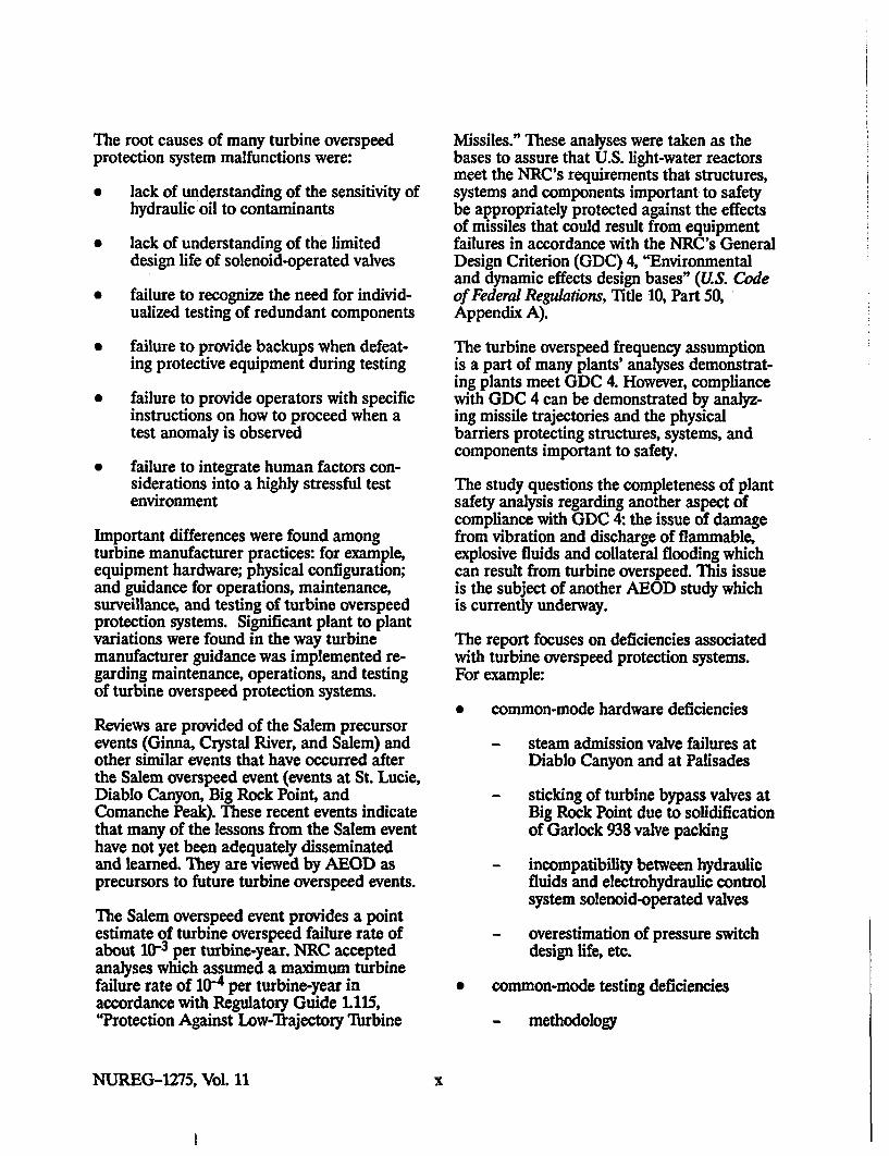
The root causes of many turbine overspeedprotection system malfunctions were:
" lack of understanding of the sensitivity ofhydraulic oil to contaminants
* lack of understanding of the limiteddesign life of solenoid-operated valves
" failure to recognize the need for individ-ualized testing of redundant components
* failure to provide backups when defeat-ing protective equipment during testing
" failure to provide operators with specificinstructions on how to proceed when atest anomaly is observed
" failure to integrate human factors con-siderations into a highly stressful testenvironment
Important differences were found amongturbine manufacturer practices: for example,equipment hardware; physical configuration;and guidance for operations, maintenance,surveillance, and testing of turbine overspeedprotection systems. Significant plant to plantvariations were found in the way turbinemanufacturer guidance was implemented re-garding maintenance, operations, and testingof turbine overspeed protection systems.
Reviews are provided of the Salem precursorevents (Ginna, Crystal River, and Salem) andother similar events that have occurred afterthe Salem overspeed event (events at St. Lucie,Diablo Canyon, Big Rock Point, andComanche Peak). These recent events indicatethat many of the lessons from the Salem eventhave not yet been adequately disseminatedand learned. They are viewed by AEOD asprecursors to future turbine overspeed events.
The Salem overspeed event provides a pointestimate of turbine overspeed failure rate ofabout 10-3 per turbine-year. NRC acceptedanalyses which assumed a maximum turbinefailure rate of 10- per turbine-year inaccordance with Regulatory Guide 1.115,"Protection Against Low-Irajectory Turbine
Missiles." These analyses were taken as thebases to assure that U.S. light-water reactorsmeet the NRC's requirements that structures,systems and components important to safetybe appropriately protected against the effectsof missiles that could result from equipmentfailures in accordance with the NRC's GeneralDesign Criterion (GDC) 4, "Environmentaland dynamic effects design bases" (US. Codeof Federal Regulations, Title 10, Part 50,Appendix A).
The turbine overspeed frequency assumptionis a part of many plants' analyses demonstrat-ing plants meet GDC 4. However, compliancewith GDC 4 can be demonstrated by analyz-ing missile trajectories and the physicalbarriers protecting structures, systems, andcomponents important to safety.
The study questions the completeness of plantsafety analysis regarding another aspect ofcompliance with GDC 4: the issue of damagefrom vibration and discharge of flammable,explosive fluids and collateral flooding whichcan result from turbine overspeed. This issueis the subject of another AEOD study whichis currently underway.
The report focuses on deficiencies associatedwith turbine overspeed protection systems.For example:
* common-mode hardware deficiencies
- steam admission valve failures atDiablo Canyon and at Palisades
- sticking of turbine bypass valves atBig Rock Point due to solidificationof Garlock 938 valve packing
- incompatibility between hydraulicfluids and electrohydraulic controlsystem solenoid-operated valves
- overestimation of pressure switch
design life, etc.
* common-mode testing deficiencies
- methodology
NUREG-1275, Vol. 11 x

- effectiveness of testing fluid cleanliness
- defeating diversity and/or redun-dancy, "smart testing"
- human factors
- procedures
* common-mode maintenance deficiencies
- frequency
- design life
Eliminating the aforementioned deficienciescan enhance the reliability and operability ofthe main turbine-generators and their over-speed protection systems, help reduce thefrequency of turbine overspeed events, andthereby raise confidence that the turbineoverspeed protection systems will operatereliably to assure conformance with assumedturbine overspeed initiator frequencies inRegulatory Guide 1.115 and compliance withGDC 4.
)d NUREG-1275, Vol. 11

FOREWORD
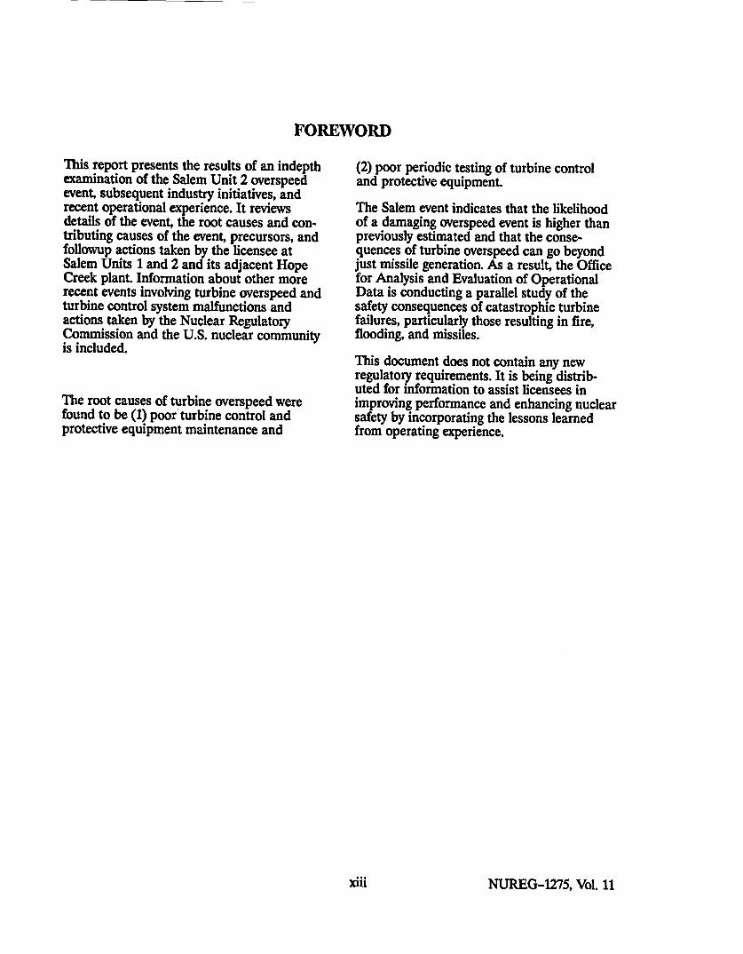
This report presents the results of an indepthexamination of the Salem Unit 2 overspeedevent, subsequent industry initiatives, andrecent operational experience. It reviewsdetails of the event, the root causes and con-tributing causes of the event, precursors, andfollowup actions taken by the licensee atSalem Units 1 and 2 and its adjacent HopeCreek plant. Information about other morerecent events involving turbine overspeed andturbine control system malfunctions andactions taken by the Nuclear RegulatoryCommission and the U.S. nuclear communityis included.
The root causes of turbine overspeed werefound to be (1) poor turbine control andprotective equipment maintenance and
(2) poor periodic testing of turbine controland protective equipment.
The Salem event indicates that the likelihoodof a damaging overspeed event is higher thanpreviously estimated and that the conse-quences of turbine overspeed can go beyondjust missile generation. As a result, the Officefor Analysis and Evaluation of OperationalData is conducting a parallel study of thesafety consequences of catastrophic turbinefailures, particularly those resulting in fire,flooding, and missiles.
This document does not contain any newregulatory requirements. It is being distrib-uted for information to assist licensees inimproving performance and enhancing nuclearsafety by incorporating the lessons learnedfrom operating experience.
xnli NUREG-1275, Vol. 11

ABBREVIATIONS
AEC U.S. Atomic Energy CommissionAEOD Analysis and Evaluation of
Operational Data (NRC'sOffice for)
AIB Availability ImprovementBulletin [Westinghouse]
AIT Augmented Inspection Team(NRC)
AST auto stop oilATr automatic turbine testing
BOP balance of plant
CAL Customer Advisory Letter[Westinghouse]
CB containment buildingCE Combustion Engineering
DEH digital electrohydraulic (controlsystem) [Westinghouse]
EDO Executive Director for Operations(NRC)
EGE emergency governor exerciser[Big Rock Point]
EHC electrohydraulic controlESFAS engineered safety feature actuation
system
HTS hand-trip solenoid
IN Information Notice
LER Licensee Event ReportLWR light-water reactor
MLEA Main Line Engineering Associates[of Exton, PA]
MOV motor-operated valveMSL main steam line
NRC U.S. Nuclear RegulatoryCommission
NRR Nuclear Reactor Regulation (NRC'sOffice of)
PG&EPSE&GPWR
RPS
Pacific Gas & Electric Co.Public Service Electric and Gaspressurized-water reactor
reactor protection system
SERT Significant Event Review Team[Salem/PSE&G]
SOV solenoid-operated valve
TIL Technical Information Letter[General Electric]
TOPS turbine overspeed protectionsystem
TS Technical SpecificationTSV turbine stop valve
W Westinghouse Electric Corporation
FPL
GEGDC
Florida Power and Light Company
General Electric CompanyGeneral Design Criterion
xv NUREG-1275, Vol. 11

1 INTRODUCTION
On November 9, 1991, a turbine overspeedevent at the Salem Unit 2 nuclear power plantcaused extensive damage to the turbine, gen-erator, and main condenser. The turbine over-speed event resulted in a hydrogen explosionand fire, as well as lube oil fires.
Although there was no loss of life or personnelinjury, the event resulted in property damageand a 6-month plant shutdown.
At the request of the U.S. Nuclear RegulatoryCommission's (NRC's) Executive Director forOperations (EDO), the NRC Office for Anal-ysis and Evaluation of Operational Data(AEOD) expanded its ongoing study of theSalem Unit 2 overspeed event in 1992.
This report presents the results of an indepthstudy of the Salem Unit 2 overspeed event,subsequent industry initiatives, and recentoperational experience. The report reviewsdetails of the event, the apparent and rootcauses of the event, precursors, and followupactions taken by the licensee at Salem Units 1and 2 and Hope Creek (an adjacent plantowned by the same utility). The reportincludes information about other more recentevents involving turbine overspeed and turbinecontrol system malfunctions and describesactions taken by the NRC, other utilities,manufacturers, and the insurance companiesthat provide liability and property damagecoverage to U.S. nuclear power plants. Thereport also delineates actions for improvingthe reliability of the turbine overspeedprotection system (TOPS) to reduce thelikelihood of experiencing a catastrophicturbine overspeed event.
2 HISTORICAL REVIEW
Turbine failures have long been recognized ashaving the potential for throwing off missilesthat can cause loss of life, extensive damage,long plant outages, and major financial loss.Many catastrophic turbine failures haveoccurred because of manufacturing or designdefects, as well as from human error. In 1973,
S. Bush (Ref. 1) published information about21 main turbine failures that occurredthroughout the world between 1950 and 1972.Bush's paper provides the basis for NRCassumptions about turbine failure rates.
Fourteen of the 21 failures generated missilesthat penetrated the turbine casing. Of these14 events, 9 were caused by manufacturingdefects or design deficiencies in the rotatingparts and occurred near or at normal operat-ing speeds. Bush noted that, due to improvedturbine design and improved manufacturingtechniques, most of these failures would beunlikely to recur. The other five overspeedevents that generated missiles were caused bycommon-mode failures--sticking of steamcontrol and dump valves. The valves wereprone to such failures because of the smallclearances around the valve stems and thepresence of foreign material. The smallclearances were also aggravated by faultyadjustments, design errors, shop errors, andfaulty materials. Information about similarmain turbine failures appears in a 1973General Electric (GE) memo.1 Of interest is a1970 event in which a low-pressure rotor of aMitsubishi turbine undergoing factory testingburst at 117 percent of rated speed. An 8-tonfragment was thrown eight-tenths of a mile.Details about a significant overspeed eventwhich did considerable damage at Uskmouth15 in the United Kingdom in 1956 are alsogermane'. The turbine oversped to 170 per-cent of rated speed and burst the low-pressurerotor. The event was caused by common-modecontamination of the lubrication and hy-draulic oil. Fine iron oxide particles whichresulted from water intrusion in the oil coolerdeposited sludge which caused simultaneoussticking of hydraulic control valves and redun-dant oil trip valves in the emergency over-speed system. Bush (Ref. 1) stated that theUskmouth failure resulted from stuck steamadmission valves which were caused bymagnetite buildup.
Most of the overspeed events described byBush (Ref. 1) occurred at non-nuclear
'General Eectric Company, Turbine Department, "Memo Re-port-Hypothetical rbine Missiles--Frobability of Occur-rence," March 14, 1973.
I NUREG-1275, Vol. 11
facilities with high-temperature steam(",1000 *F). High-temperature steam pro-moted the buildup of "boiler salts"-that is,salts or oxides-on the steam admissionvalves. The buildup of such foreign materialswould not be expected at the lower tempera-tures in light-water reactors (LWRs) (A650 *Fsteam). In addition, tight control of waterchemistry at LWRs reduces the likelihood forcommon-mode sticking of turbine steamadmission valves. In the U.S., early-vintagepressurized- water reactors (PWRs) usedphosphate-type secondary-side water treat-ment. The phosphates were found to be amajor cause of turbine steam valve sticking.Switching from phosphate treatment toall-volatile treatment reduced the salt buildupproblems and improved turbine valve relia-bility. Bush also noted that the incidence ofoverspeed events markedly decreased (innon-nuclear plants) between 1961 and 1972because turbine valves were exercised daily orweekly during load change tests. Exercisingthe valves eliminated the buildup of depositsin the valve stem guide area.
In the early 1970's, when Bush wrote hispaper, experience with main turbine failuresled to estimates of turbine missile frequencyof about 10i4 per turbine per year. However,Bush's paper indicated the expectation thattechnological improvements in manufacturingand testing would reduce the turbine missilegeneration probabilities. The turbines used atmost U.S. nuclear plants benefitted fromadvancements in manufacturing and inspec-tion techniques that were not available for theturbines that failed from 1950 through 1972. Ifperiodic inspections are performed properlyand defects repaired satisfactorily, catastroph-ic main turbine failures would not be expectedto occur at U.S. nuclear plants unless therewas a turbine overspeed. Because of earlierturbine failure history, the U.S. AtomicEnergy Commission (AEC), its successoragency, the NRC, and the licensees focused onsteam admission valve operability and diver-sity of overspeed protection systems (types ofspeed sensors) as ways of minimizing thedamage to the plants from such credibleevents. Based upon earlier fossil plant
experience and the perceived diversity ofTOPS (i.e., electronic, mechanical, electro-hydraulic speed sensors and control fluidsubsystems), the AEC/NRC concentrated onverification that the steam admission valveswere not stuck, while overlooking other criticalhydraulic, mechanical, and electrical sub-system components such as solenoid-operatedvalves (SOVs), pressure switches, relays, etc.Although NRC Standard Review Plan 10.2(Ref. 2) noted that such components needed tobe testable, the NRC did not require surveil-lance testing of these components. Plantdesigns were analyzed for turbine failures as aresult of which missiles could penetrate thecontainment building (CB) and affect safetysystems. To protect against turbine-generatedmissiles, the turbines at many plants wereoriented in a "favorable direction" with theaxis of rotation perpendicular to the CB sothat turbine-generated missiles would not belikely to strike the CB.
Using the methodology outlined in RegulatoryGuide 1.115 (Ref. 3) to show that the likeli-hood of turbine missiles causing unacceptabledamage to safety-related equipment was lessthan 16-7 per turbine-year, licensees were ableto demonstrate that their plants' mainturbine-generators met the NRC's licensingrequirements of General Design Criterion(GDC) 4 of Appendix A to Part 50, Title 10 ofthe Code of Federal Regulations (10 CFR[Ref. 4]). The Regulatory Guide 1.115methodology is as follows:
The probability of a turbine missilestriking safety-related equipment andcausing unacceptable damage is referredto as P4. It is the product of 3 proba-bilities (i.e., P4 = PI x P2 x P3)
P1 probability that a high energyturbine missile will penetrate itscasing
P2 probability that the high energyturbine missile will strike safety-related equipment (referred to asthe "strike" probability)
P3 probability that the high energyturbine missile strike will cause
NUREG-1275, Vol. 11 2

unacceptable damage to safety-related equipment (referred to asthe "damage" probability).
In accordance with Regulatory Guide 1.115, ifa licensee could demonstrate P4 to be lessthan 10-7 assuming P1 equals 104 (basedupon Bush [Ref. 1]), the plant's main turbine-generator was considered to have satisfiedGDC 4 turbine missile concerns. Such analy-ses overlooked vibration-induced fluid leaks(of hydrogen and of lubrication and hydraulicoils) that could accompany a destructiveturbine overspeed.
A 1987 NRC staff review of WestinghouseElectric Corporation M topical reports onturbine missiles, turbine failures, and turbineoverspeed noted that based upon variouslicensing applications, the turbine missile"strike and damage probability" (i.e., theprobability of having a high energy turbinemissile strike and cause unacceptable damageto safety-related systems) was estimated to bebetween 10-3 and 10W2 for unfavorably ori-ented turbinesla, and between 10-4 and 10-3for favorably oriented turbines. The NRCstaff's safety evaluation report (Ref. 5)approved the use of the _W topical reports. Itprovided the foundation for licensing actionsin which the Technical Specification (TS)requirements for turbine overspeed testingwere relaxed for plants with 3Y turbines.Reference 5 noted the large uncertainty in thelikelihood for turbine missile generation:
... depending on the specificcombination of material properties,operating environment, and mainte-nance practices, the P1 (probabilityof turbine missile generation) canhave values between 10-9 to 10-1 perturbine-year depending on test andinspection intervals.
The NRC staff's safety evaluation report(Ref. 5) discouraged the elaborate calculationof the strike and damage probabilities for low-trajectory turbine missiles. As an alternative itgave credit of 10-3 for the product of the1I'brbines with the axis of rotation parallel to the CB.
strike and damage probabilities for favorablyoriented turbines and 10-2 for unfavorablyoriented turbines.
The turbine system reliability criteria pro-vided as guidance in Reference 5 have beenreproduced in Thble 1.
A 1987 W topical report sponsored by severalW turbine owners1b supported relaxing thefrequency with which the turbine steamadmission valves are exercised. The topicalreport estimated the probabilities of turbinemissile ejections due to overspeed at therespective plants. If the November 9, 1991,overspeed event at Salem Unit 2 is considered,the W topical report's probabilistic assess-ment of turbine missile ejections at SalemUnit 2 can be shown to be nonconservative bythree to five orders of magnitude (see Fig-ure 1). The assessment is nonconservative andtherefore invalid because the turbine and itsoverspeed protection system were not main-tained and tested in the manner assumed inthe analysis. Common-mode errors involvinghuman factors and equipment could not beand were not quantified or included in theassessment. This issue is discussed in detail inSection 7.4 of this report.
Several turbine overspeed events have oc-curred at U.S. nuclear power plants, althoughthe Salem Unit 2 event is the only one knownto have generated missiles. Turbine overspeedevents at U.S. LWRs are listed in Tible 2. TheSalem Unit 2 event caused significant damageand resulted in a 6-month outage. Chapter 3of this report provides more details. Appen-dix A contains a list of the manufacturers ofmain turbines and generators at all U.S.LWRs.
At U.S. nuclear power plants, main turbinesare categorized as balance of plant (BOP)equipment. However, as noted below, at manyplants the turbine trip function is part of theengineered safety feature actuation system(ESFAS) instrumentation, the safety-related
lbWestinghouse Electric Corporation (Westinghouse Proprie-tazlas 2) Report WCA&-11525, Probabilistic EvaluationofRuction uiIrbine Valve Te•t Frequency," June 1987.
3 NUREG-1275, Vol. 11

Table 1 Turbine system reliability criteria*
P1 = Tlrbine missile ejection probability, yr"
Favorably UnfavorablyOriented Turbine Oriented Turbine Required Licensee Action
(A) P1 < 10-4 P1 < 10-5 This is the general, minimum reliabilityrequirement for loading the turbine andbringing the system on line.
(B) 10-4 < P1 < 10-3 10-5 < P1 < 10-4 If this condition is reached during operation,the turbine may be kept in service until thenext scheduled outage, at which time thelicensee is to take action to reduce P 1 tomeet the appropriate A criterion (above)before returning the turbine to service.
(C) 1i-3 < P1 < 10-2 104 < P1 < 10-3 If this condition is reached during operation,the turbine is to be isolated from the steamsupply within 60 days, at which time thelicensee is to take action to reduce P1 tomeet the appropriate A criterion (above)before returning the turbine to service.
(D) 10-2 < p, 10-3 < P1 If this condition is reached at any timeduring operation, the turbine is to be iso-lated from the steam supply within 6 days, atwhich time the licensee is to take action toreduce P1 to meet the appropriate A criter-ion (above) before returning the turbine toservice.
'Reference 5 (NRC safety evaluation of W topical reports providing probabilistic assessments of turbine failures, turbine overspeed, andturbine missiles). These criteria provide uidance for use in determining turbine disc inspections and maintenance and testing schedulesfor turbine control and overspeed protection systems.
NUREG-1275, Vol. 11 4
10-8
lo-e
xi 10-7
0CL
10 8I I I I . I I I . I I I I I I
0 1 2 3 4 5 6 7 8 9 10 11 12 13
INTERVAL BETWEEN TURBINE VALVE TESTS (months)
Figure 1 W-estimated probability of missile ejection from Salem Unit 2 turbineas a function of valve test interval (reproduced with permission fromWestinghouse Electric Corporation)
!
m
tm
m
5 5 NUREG-1275, Vol. 11

Table 2 U.S. nuclear plant turbine overspeed events*
Plant Date Maximum turbine speed
Yankee Rowe < 1960 (Factory Testing) 120 %Yankee Rowe"* 1960-1980 20 events ; 111 %
San Onofre Unit 1 July 1972 133 %
Davis Besse September 1977 > 111 %
Haddam Neck January 1982 > 128 %
D.C. Cook Unit 2 January 1983 > 112 %
Crystal River Unit 3 February 1988 103 %Three Mile Island Unit 1 September 1991 > 109 %
Salem Unit 2*** November 1991 160 %
St. Lucie Unit 2 April 1992 103 %
Diablo Canyon Unit 1 September 1992 104 %
Beaver Valley Unit I October 1993 > 111 %
*In recent years, several destructive turbine overspeed events have also occurred at U.S. fossil-powered plants.Events in which turbine speed exceeded 100 percent but was less than 109 percent are included because they were theresult of operational TOPS equipment malfunctions and some of them are viewed as precursors to more senous(destructive) overspeed events.
This table should not be construed as being complete since other events may not have been reported.
lypically, mechanical overspeed testing at 110 percent overspeed is rformed once per fuel cycle (W and GE turbineinstruction manuals recommend testing every 6 to 12 months and aTer certain maintenance work is performed).
"'Yankee Rowe sustained major turbine damage in 1980 (overspeed not involved during that event).
"The Salem Unit 2 event was the only overspeed event that generated missiles which penetrated the casing.
function of which is to reduce the potential forsevere overcooling transients and mitigate theconsequences of steam generator overfill. Be-cause of concerns about damage from turbineoverspeed and turbine missiles, TS of manyplants require that at least one TOPS be oper-able, that the steam admission valves undergoperiodic test cycling and inspection, and thatTOPS channels be calibrated periodically.
It is important to note that, although the tur-bine trip system serves an ESFAS functionand is linked to the reactor protection system(RPS), the limiting conditions for operationfor the TOPS instrumentation are not in-cluded in TSs. At all W plants and at somePWRs designed by other manufacturers, theP4 interlock provides for a turbine trip signal
after a reactor scram. At some of those plants,the P-4 interlock also provides for a turbinetrip signal on high steam generator level.Plants that have TS requirements for periodicESFAS surveillance testing of the turbine tripfunction are not required to test each train ofturbine trip signals independently. In boiling-water reactors (BWRs), the turbine trip fea-ture is integrally connected to the RPS andthe turbine trip function for BWRs is also anESFAS feature. In PWRs and BWRs, inspec-tion and maintenance requirements for mainturbine electrohydraulic control (EHC) orauto stop oil (AST) systems and for theircomponent SOVs, pressure switches, etc.,associated with turbine trip, are not specific-ally addressed in plant TSs.
NUREG-1275, Vol. 11 6
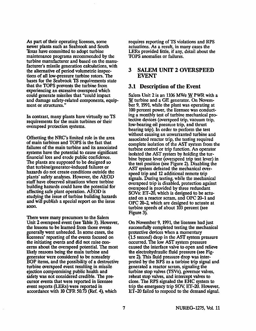
As part of their operating licenses, somenewer plants such as Seabrook and SouthTexas have committed to adopt turbinemaintenance programs recommended by theturbine manufacturer and based on the manu-facturer's missile generation calculations, withthe alternative of period volumetric inspec-tions of all low-pressure turbine rotors. Thebases for the Seabrook TS requirements statethat the TOPS prevents the turbine fromexperiencing an excessive overspeed whichcould generate missiles that "could impactand damage safety-related components, equip-ment or structures."
In contrast, many plants have virtually no TSrequirements for the main turbines or theiroverspeed protection systems.
Offsetting the NRC's limited role in the areaof main turbines and TOPS is the fact thatfailures of the main turbine and its associatedsystems have the potential to cause significantfinancial loss and erode public confidence.The plants are supposed to be designed sothat turbine/generator-induced failures orhazards do not create conditions outside theplants' safety analyses. However, the AEODstaff have observed situations where turbinebuilding hazards could have the potential foraffecting safe plant operation. AEOD isstudying the issue of turbine building hazardsand will publish a special report on the issuesoon.
There were many precursors to the SalemUnit 2 overspeed event (see Table 3). However,the lessons to be learned from those eventsgenerally went unheeded. In some cases, thelicensees' reporting of the events focused onthe initiating events and did not raise con-cerns about the overspeed potential. The mostlikely reasons being the main turbine andgenerator were considered to be nonsafetyBOP items, and the possibility of a destructiveturbine overspeed event resulting in missileejection compromising public health andsafety was not considered credible. The pre-cursor events that were reported in licenseeevent reports (LERs) were reported inaccordance with 10 CFR 50.73 (Ref. 4), which
requires reporting of TS violations and RPSactuations. As a result, in many cases theLERs provided little, if any, detail about theTOPS anomalies or failures.
3 SALEM UNIT 2 OVERSPEED
EVENT
3.1 Description of the Event
Salem Unit 2 is an 1106 MWe W PWR with aW turbine and a GE generator. On Novem-ber 9, 1991, while the plant was operating at100 percent power, the licensee was conduct-ing a monthly test of turbine mechanical pro-tective devices (overspeed trip, vacuum trip,low-bearing oil pressure trip, and thrustbearing trip). In order to perform the testwithout causing an unwarranted turbine andassociated reactor trip, the testing requiredcomplete isolation of the AST system from theturbine control or trip function. An operatorisolated the AST system by holding the tur-bine bypass lever (overspeed trip test lever) inthe test position (see Figure 2). Disabling theAST system defeated the mechanical over-speed trip and 12 additional remote tripsignals. During testing, while the mechanicaloverspeed trip is disabled, protection againstoverspeed is provided by three redundantSOVs: ET-20, which is designed to be actu-ated on a reactor scram, and OPC 20-1 andOPC 20-2, which are designed to actuate atturbine speeds of about 103 percent (seeFigure 3).
On November 9, 1991, the licensee had justsuccessfully completed testing the mechanicalprotective devices when a momentary(1.5 second) drop in the AST system pressureoccurred. The low AST system pressurecaused the interface valve to open and relievethe electrohydraulic fluid pressure (see Fig-ure 2). This fluid pressure drop was inter-preted by the RPS as a turbine trip signal andgenerated a reactor scram, signaling theturbine stop valves (TSVs), governor valves,reheat stop valves, and intercept valves toclose. The RPS signaled the EHC system totrip the emergency trip SOV, ET-20. However,ET-20 failed to respond to the demand signal.
7 NUREG-1275, Vol. 11
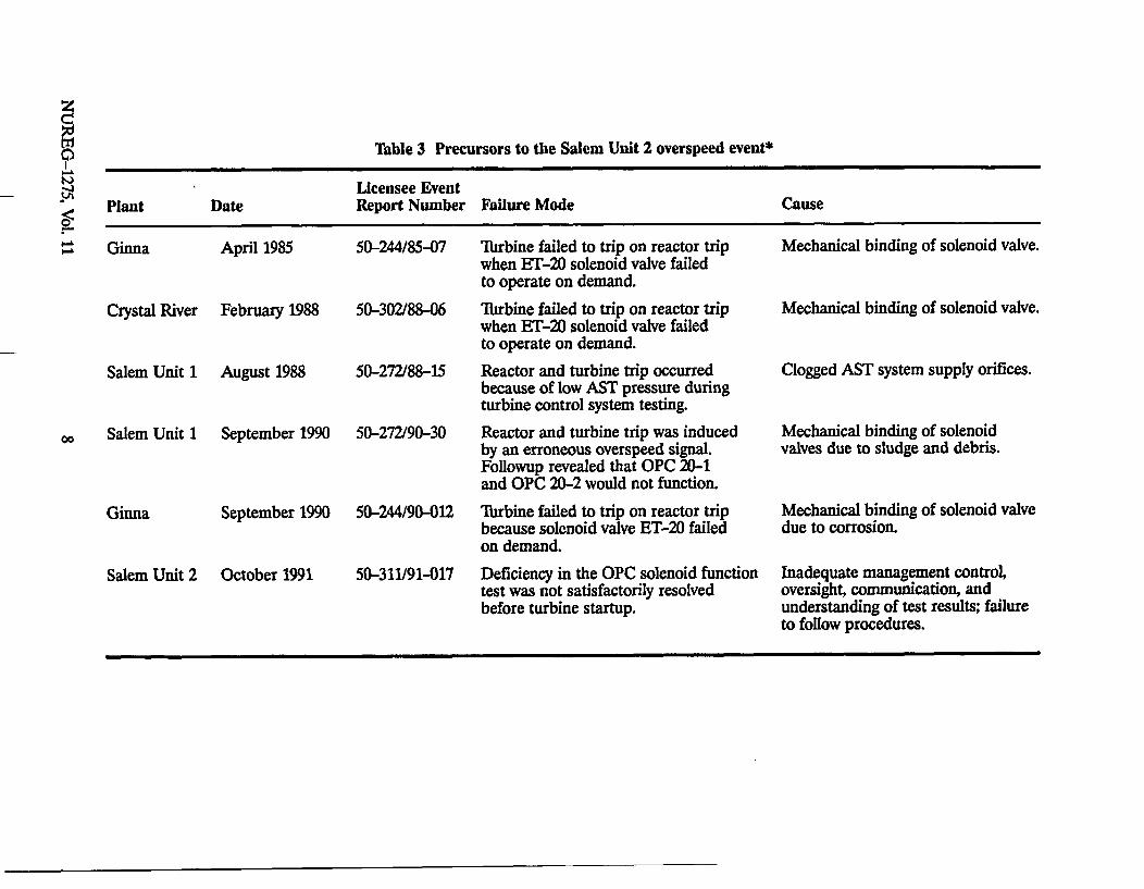
Table 3 Precursors to the Salem Unit 2 overspeed event*
Licensee EventPlant Date Report Number Failure Mode Cause
Ginna April 1985 50-244/85-07 Turbine failed to trip on reactor trip Mechanical binding of solenoid valve.when ET-20 solenoid valve failedto operate on demand.
Crystal River February 1988 50-302/88-06 Turbine failed to trip on reactor trip Mechanical binding of solenoid valve.when ET-20 solenoid valve failedto operate on demand.
Salem Unit 1 August 1988 50-272/88-15 Reactor and turbine trip occurred Clogged AST system supply orifices.because of low AST pressure duringturbine control system testing.
Salem Unit 1 September 1990 50-272/90-30 Reactor and turbine trip was induced Mechanical binding of solenoidby an erroneous overspeed signal. valves due to sludge and debris.Followup revealed that OPC 20-1and OPC 20-2 would not function.
Ginna September 1990 50-244/90-012 lbrbine failed to trip on reactor trip Mechanical binding of solenoid valvebecause solenoid valve ET-20 failed due to corrosion.on demand.
Salem Unit 2 October 1991 50-311/91-017 Deficiency in the OPC solenoid function Inadequate management control,test was not satisfactorily resolved oversight, communication, andbefore turbine startup. understanding of test results; failure
to follow procedures.
00

UECMO-HYD]RAUUC FLUID SYSTEM AUTO-STOP OIL SYSTEM
Figure 2 Schematic of Salem turbine control system prior to November 1991
INTERFACE VALVE
HPOIL j TEST IiSUPPLY Kw E(FRWM ••
LUBE OIL ------ - 0SYSTEM)CCsys I
OVERSPEEDPROTECTION
LOGIC H-
Figure 3 Schematic of Salem type (generic) emergency and overspeed protectioncontrol system before November 1991
The 30-second reverse power protection timerstarted at the time of the trip signal. When the1.5-second low AST pressure perturbationcleared, the interface valve closed, the electro-hydraulic trip fluid repressurized, and theTSVs started to reopen. Because the ASTpressure switch 63-3/AST was incorrectly set,the turbine's analog electrohydraulic systemdid not detect the initial turbine trip con-dition. If 63-3/AST had been set correctly,and had functioned properly, the analog elec-trohydraulic system would probably havereduced the governor valve demand to zerowhen the initial AST system pressure dropoccurred. The analog electrohydraulic systemcould also have prevented the governor valvefrom reopening by actuating an auto-stop trip.However, the failure of the 63-3/AST toactuate allowed the governor valves to reopenwhen the AST pressure perturbation cleared.The main generator output breakers openedas designed (the signal for main generatoroutput breakers to open comes from the RPSwith a 30-second time delay). However, about
11 seconds after the generator output breakersopened, the TSVs reached the open position(> 90 percent open). At that time, theturbine-generator was unloaded (disconnectedfrom the grid) and receiving steam throughthe admission valves. The turbine started tooverspeed. As the turbine speed approached103 percent, the overspeed protection con-troller signalled for SOVs OPC 20-1 and OPC20-2 to shift positions to dump electrohy-draulic trip fluid to close the intercept andgovernor valves to limit the overspeed con-dition to 103 percent. However, both SOVsfailed upon demand. The operator at the frontstandard panel continued to hold the trip testlever in the test position, disabling themechanical overspeed trip and the 20/ASTelectrical turbine trip solenoid valve.
The turbine generator oversped to anestimated 2900 rpm (about 60 percent abovethe design of 1800 rpm). The shaft vibratedseverely and turbine missiles (blading)penetrated the 1-1/4 inch-thick carbon steel
NUREG-1275, Vol. 11 10
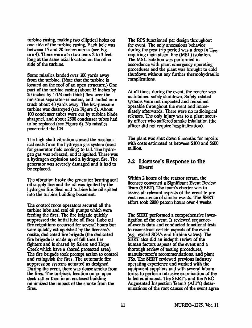
turbine casing, making two elliptical holes onone side of the turbine casing. Each hole wasbetween 15 and 20 inches across (see Fig-ure 4). There were also two tears 2 to 3 feetlong at the same axial location on the otherside of the turbine.
Some missiles landed over 100 yards awayfrom the turbine. (Note that the turbine islocated on the roof of an open structure.) Onepart of the turbine casing (about 15 inches by20 inches by 1-1/4 inch thick) flew over themoisture separator-reheaters, and landed on atruck about 40 yards away. The low-pressureturbine was destroyed (see Figure 5). About100 condenser tubes were cut by turbine bladeshrapnel, and about 2500 condenser tubes hadto be replaced (see Figure 6). No missilespenetrated the CB.
The high shaft vibration caused the mechan-ical seals from the hydrogen gas system (usedfor generator field cooling) to fail. The hydro-gen gas was released, and it ignited. There wasa hydrogen explosion and a hydrogen fire. Thegenerator was severely damaged and it had tobe replaced.
The vibration broke the generator bearing sealoil supply line and the oil was ignited by thehydrogen fire. Seal and turbine lube oil spilledinto the turbine building basement.
The control room operators secured all theturbine lube and seal oil pumps which werefeeding the fires. The fire brigade quicklysuppressed the initial lube oil fires. Lube oilfire reignitions occurred for several hours butwere quickly extinguished by the licensee'sonsite, dedicated fire brigade (the dedicatedfire brigade is made up of full time firefighters and is shared by Salem and HopeCreek which have a shared protected area).The fire brigade took prompt action to controland extinguish the fires. The automatic firesuppression systems actuated as designed.During the event, there was dense smoke fromthe fires. The turbine's location on an opendeck rather than in an enclosed buildingminimized the impact of the smoke from thefires.
The RPS functioned per design throughoutthe event. The only anomalous behaviorduring the post trip period was a drop in Taerequiring main steam line (MSL) isolation.The MSL isolation was performed inaccordance with plant emergency operatingprocedures and the plant was brought to coldshutdown without any further thermohydrauliccomplications.
At all times during the event, the reactor wasmaintained safely shutdown. Safety-relatedsystems were not impacted and remainedoperable throughout the event and imme-diately afterwards. There were no radiologicalreleases. The only injury was to a plant secur-ity officer who suffered smoke inhalation (theofficer did not require hospitalization).
The plant was shut down 6 months for repairswith costs estimated at between $100 and $600million.
3.2 Licensee's Response to theEvent
Within 2 hours of the reactor scram, thelicensee convened a Significant Event ReviewTeam (SERT). The team's charter was toassess all relevant aspects of the event to pre-vent recurrence of similar events. The SERTeffort took 2000 person hours over 4 weeks.
The SERT performed a comprehensive inves-tigation of the event. It reviewed sequence-of-events data and conducted functional teststo reconstruct certain aspects of the event(e.g., cycled SOVs and turbine valves). TheSERT also did an indepth review of thehuman factors aspects of the event and athorough review of testing procedures,manufacturer's recommendations, and plantTSs. The SERT reviewed previous industryoperating experience and worked with theequipment suppliers and with several labora-tories to perform intrusive examination of thefailed equipment. The SERT's and the NRCAugmented Inspection Tbam's (AIT's) deter-minations of the root causes of the event agree
11 NUREG-1275, Vol. 11

'Ilk.11
<I>
I \ .
ha
'p"A
I, /I),
Figure 4 Photograph: Salem Unit 2, showing holes in turbine casing
NUREG-1275, Vol. 11 12
7j4
I•
11-1
ifkiwýi, ý- --
4-
I! i .1
* 14
A...
ýj
) f ~iK~~
.44
II,
*44 14
"4-
Figure 5 Photograph: Salem Unit 2, showing damage to low-pressure turbine
13 NUREG-1275, Vol. 11

Figure 6 Photograph: Salem Unit 2, showing condenser damage
NUREG-1275, Vol. 11 14
closely. Root causes determined by the SERTand ArT appear in Section 3.4 of this report.
The SERT reportlc made 32 recommendationsfor corrective action. The recommendationsappear in Appendix B of this report. The firstsix recommendations were categorized by thelicensee as relating to plant design:
(1) evaluation of the turbine protec-tion systems and designenhancements
(2) root cause assessment of SOVfailures and implementation ofcorrective actions to preventrecurrence
(3) determination of the source ofthe foreign material that enteredthe AST system and could havecaused the AST system pressureperturbation
(4) evaluation of the need for cor-recting human factor deficienciesat the front standard panel
(5) determination of all sources ofsteam that fed into the turbinewhich resulted in the overspeedevent
(6) evaluation of the adequacy ofAST pressure switch settings
The next 22 SERT recommendations werecategorized as relating to programs. Theserecommendations address adequacy of, andthe need for changes to, programs associatedwith
* surveillance testing* maintenance* human factors enhancements* operator training
lePublic Service Electric and Gas Company, Significant EventResense rbam (SERT) Report No. SSR91-6"SalemUn9t 2 ReactorTurbine 'Ilip and lbrbine/Generator Failureof November 9, 1991," December 20, 1991.
* technical specifications* emergency procedures (including
fire fighting)* review and feedback of
operational experience
The final four SERT recommendations relatedto personnel. They address human behavior,human factors that contributed to the over-speed event, and the corrective actions neededto prevent recurrence (e.g., failure to examineOPC 20-1 and OPC 20-2 testing anomaliesduring the October 20, 1991, testing). Theyalso address the decision to defer replacementof Unit 2 SOVs during the spring 1991 "mini-outage," and lessons-learned training regard-ing the November 1991 overspeed event.
By September 1992, the licensee implementedmost of the 32 recommendations in the SERTreport, with almost all of the remainingrecommendations scheduled for completionbefore the end of 1992. It is important to notethat most of the recommendations applied toSalem Unit 1 as well as Salem Unit 2. Sec-tion 4.1 describes the major hardware, pro-cedural, and testing modifications made at theSalem plants as a result of the overspeedevent. In addition, the technical staff at thelicensee's adjacent plant, Hope Creek2, hasreviewed the SERT report recommendationsfor applicability and has taken correctiveaction. Section 4.2 of this report summarizesHope Creek's review and the correctiveactions.
3.3 NRC Responses to the Event
3.3.1 Immediate Actions
After being notified of the event, the NRCformed an AIT consisting of two Salemresident inspectors, three regional basedinspectors, and two engineers from NRCheadquarters. The team arrived on site onNovember 10, 1991.
The AIT's primary tasks were to gather thefacts, determine the root causes, and identify2Hope Creek is a BWR with a GE turbine and generator. It islocated on the same site as Salem Units 1 and 2.
15 NUREG-1275, Vol. 11

potential generic issues. The results of theAIT efforts appear in References 6 and 7.
When the causes of the overspeed event wereknown, NRC's generic communicationsbranch issued Information Notice (IN) 91-83(Ref. 8) to alert licensees to the details of theevent. The licensees were expected to reviewthe information for applicability to theirplants and consider actions to prevent similaroccurrences.
3.3.2 Longer Term Actions
Based upon the AMT's findings, the NRCRegion I Administrator recommended to theDirector of the Office of Nuclear ReactorRegulation (NRR) that the generic concernsraised by the Salem Unit 2 overspeed event beevaluated to determine if regulatory action orgeneric communications were warranted(Ref. 7). The generic concerns included thefollowing:
" TS inadequacies regarding TOPS
Standard Technical Specifications requireonly one TOPS operable and do not ad-dress redundancy or diversity. In addi-tion, the TSs address only the operabilityof the steam admission valves and do notrequire surveillance of the control systemand its components (SOVs, pressureswitches, etc.).
* SOV failures
These failures raise the question ofwhether a generic communication isneeded to focus licensee's attention onTOPS SOVs with regard to application,design and design life, maintenance,quality, and surveillance.
e. Tiurbine generator fires and their effects
upon nuclear safety-related equipment
* BOP equipment
Is enough regulatory attention paid toBOP equipment and systems that could"adversely affect or challenge the opera-
tion of safety-related equipment"? Alsonoted was the fact that turbine controlsystems affect and are affected by RPSlogic, whereas NRC inspection programspay little attention to operability andmaintenance of BOP systems.
In response to the NRC Region I Administra-tor's letter (Ref. 9), the Associate Director forProjects, NRR, noted that according to theNRC's policy statement on TS improvements,new Standard Technical Specifications "relo-cate requirements for turbine overspeedprotection to licensee controlled documents"(i.e., procedures). In early 1992, NRR reviewedthe Salem Unit 2 turbine overspeed event.The review found that the TSs of 18 of 45 Wplants do not require the ESFAS turbine tripfunction-the P4 interlock-to be tested. Asnoted in Chapter 2 of this report, the P4 in-terlock reduces the potential for severe over-cooling transients and events that could leadto steam generator overfill. It appears that thelack of an adequate test for the P-4 interlockcontributed to the Salem overspeed event.
The Associate Director for Projects, NRR,noted (Ref. 9) that with regard to the need foran additional generic communication onSOVs, IN 91-83 was adequate and that nofurther generic communications on SOVswere warranted at that time (February 1992).It was also noted (Ref. 9) that NRR wasevaluating the issue of fire vulnerabilities. TheAssociate Director for Projects, NRR, notedthat the issues concerning BOP equipmentwill be covered by the NRC's maintenancerule (10 CFR 50.65 [Ref. 4]).
3.4 Root Causes of the EventThe NRC-AJT report (Ref. 6) and the SERTreport2a were in complete agreement on the"contributing causal factors" for the Novem-ber 9, 1991, overspeed event. Sections 3.4.1 to3.4.6 summarize those "contributing causalfactors," many of which can be viewed as rootcauses.
2aPublic Service Electric and Gas Company, Significant EventResponse'lbam(SER') Report No. SSR 91-06, "SalemUrt2ReactoriTurbine "flip and TIrbine/Generator Failureof November 9, 1991," December 20, 1991.
NUREG-1275, Vol. 11 16

3.4.1 Equipment Failure
All three overspeed system SOVs weremechanically bound and so could not shiftposition on demand. Because of testinginadequacies or human errors, the failureswere not detected by previous testing.
3.4.2 Inadequate Preventive Maintenance
(1) The licensee failed to recognize the needfor SOV or AST pressure switch preven-tive maintenance. This failure was partlydue to the absence of manufacturer orturbine vendor recommendations forpreventive maintenance.
(2) The licensee failed to perform correctiveand preventive SOV maintenance asidentified by Salem Unit 1 operatingexperience, in accordance with a pre-viously committed to schedule.
3.4.3 Inadequate Review and Feedback ofOperational Experience
The licensee failed to recognize or follow upon five precursor events involving turbinecontrol systems and SOVs (two events atSalem Unit 1, two events at Ginna, and oneevent at Crystal River Unit 3 [see 'ibble 3]).
3.4.4 Inadequate Surveillance Testing
(1) Most of the automatic turbine trip signalsand features are bypassed during monthlytesting of the turbine mechanical protec-tive devices. Turbine overspeed protectionreverts to a backup system with an elec-trically actuated emergency trip SOV(ET-20) and two redundant electricallyactuated overspeed protection SOVs(OPC 20-1 and 20-2). However, beforeperforming the monthly tests, the licenseedid not verify the operability of the emer-gency trip SOV (ET-20) and failed torecognize that the overspeed protectionSOVs (OPC 20-1 and 20-2) had bothfailed their surveillance tests when theywere performed 3 weeks earlier.
(2) Surveillance testing of redundant SOVs(OPC 20-1 and 20-2) could not reveal a
single failure of either SOV The samewas true for simultaneous surveillancetesting of ET-20 and AST 20. (The tur-bine manufacturer did not provide anyguidance for testing of SOVs, individuallyor as a group.)
(3) Operators and supervisors allowed tur-bine startup (October 20, 1991) whensurveillance testing indicated malfunc-tions of the TOPS (OPC 20-1 and 20-2).They thought that concurrent failure ofboth SOVs was incredible and thatsomething must have been wrong withtheir test procedure.
3.45 Human Factors Deficiencies inFront Standard Testing
(1) To perform the test, the necessity to holdthe overspeed trip-test lever in an awk-ward position for about 20 minutes.Furthermore, there was no positive indi-cation to allow the operator to determineif the overspeed trip-test lever was in thetest or the normal position. In addition,the amount of lever movement needed totake the lever out of the test position wasonly about 1 inch. The total range of levermotion was only 2 inches. Inadvertentmovement out of the test position duringtesting would result in a reactor scram.
(2) Absence of communication between thecontrol room and front standardoperator.
(3) Absence of turbine speed indication tothe operator at the front standard (atachometer at the front standard hadbeen disconnected and abandoned in1986).
3.4.6 Test Lever
Although the SERT report noted that the rootcause of the initial reactor scram was foreignmaterial blockage of a reducing orifice in theAST system, the licensee noted that it couldnot rule out the possibility that the operatorholding the test lever at the turbine's frontstandard may have allowed the lever to moveslightly, thereby causing the AST systempressure perturbation.
17 NUREG-1275, Vol. 11
Corrective actions that were taken by thelicensee at both Salem units are described inSection 4.1 of this report.
4 NUCLEAR INDUSTRYINITIATIVES AFTER THESALEM UNIT 2 OVERSPEEDEVENT
The Salem Unit 2 overspeed event surprisedmost people in the nuclear industry. As notedin Section 2, a destructive overspeed event ata U.S. nuclear power plant resulting fromcommon-mode SOV failures was consideredvery unlikely. Nonetheless, after being alertedto the fact that the event occurred, most of thepersons in the nuclear industry who werecontacted indicated that their organizationtook positive steps to prevent a recurrence.The amount of attention paid to the issue ofturbine overspeed has varied among organiza-tions. The following sections discuss actionstaken by individual utilities contacted, themajor turbine manufacturers, the NRC, andthe major U.S. nuclear insurers.
4.1 Public Service Electric and GasCompany at Salem Units 1and 2
As noted in Section 3.2, within 2 hours afterthe turbine overspeed event, Public Service
Electric and Gas Company (PSE&G) formeda SERT to assess all relevant aspects of theevent to prevent similar events. The SERTthoroughly investigated the root causes of theevent and made 32 recommendations forcorrective action (Section 3.2 and Appendix Bof this report contain summaries and descrip-tions of those recommendations, respectively).
The licensee implemented almost all of theSERT recommendations at Salem Units 1and 2 before the end of 1992. In addition tocommitting to implementing the SERT's32 recommendations, the licensee imple-mented commitments3 that it had made inresponse to the NRC-ArT that investigatedthe overspeed event (see Section 3.3 fordiscussion of the AIT's activities).
Table 4 highlights the major hardware, pro-grammatic, and procedural modifications thatPSE&G has made at Salem Units 1 and 2 as aresult of the overspeed event in accordancewith the SERT's findings and the NRC-AlT'sfindings.
4.2 Public Service Electric and GasCompany at Hope Creek
Hope Creek is a 1067 MWe BWR with a GEmain turbine and generator. It is located onthe same site as Salem Units 1 and 2.
3Some of those commitments overlap SERT recommendations.
Table 4 Major modifications* made at Salem Units I and 2
Modifications Made at Salem Units 1 and 2 After the November 9, 1991, Overspeed Event
0 Installed turbine speed indication at the front standard0 Improved communication between front standard operator and control room* Installed a backup turbine trip SOV to enable automatic protective turbine trip during testing0 Replaced original 20/AST solenoid0 Installed a filter in the AST header0 Installed a detent handle on the front standard (see Figure 10)• Added an additional AST pressure switch* Made system modifications to enable independent, full functional hydraulic operational periodic
testing of all four turbine protection SOVs
*Hardware, programmatic, procedural, etc.
NUREG-1275, Vol. 11 18

A few days after the Salem Unit 2 overspeedevent, PSE&G formed a team to perform alessons-learned review of the Salem Unit 2overspeed event and assess programs asso-ciated with the operation, maintenance, andtesting procedures for the main turbine atHope Creek. The Hope Creek Review Tebamalso assessed the Salem SERT report forapplicability to Hope Creek. They also re-viewed Hope Creek's operating procedures forTOPS relative to the turbine manufacturer's(GE's) guidance.
With regard to turbine testing vulnerabilities,the review team found that perhaps the mostimportant differences between Salem andHope Creek turbine testing are that, at HopeCreek, the GE main turbine mechanicaloverspeed trip is not bypassed during electri-cal overspeed trip testing and, conversely, theelectrical overspeed trip is not bypassedduring mechanical overspeed trip testing.Furthermore, other turbine trip tests do notdisable the overspeed trips3 ,b. Most of theGE main turbine control systems used atnuclear power plants have turbine testingconfigurations similar to Hope Creek. (Thedifferences between design and guidance atSalem and Hope Creek are indicative of
kJ. L Thompson, PSE&G, memorandum to B. E. Hall,"Main Tarbme 'fip System MThsting," November 22, 1991.
34j. J. Hagan, FSE&G, memorandum to S. 1IBruna, "HopeCreek Review/Actions Associated With Salem Unit IIilirbine Overspeed Event," January 27,1992.
generic differences between GE and Wdesigns and guidance.)
The review team did identify some areaswhere enhancements to TOPS procedures,equipment, and testing at Hope Creek wouldbe appropriate (see Table 5 for a list of themost significant items).
As a result of its reviews, the licenseeconcluded that the turbine testing at HopeCreek had been conducted adequately.
4.3 Westinghouse Power GenerationBusiness Unit
Immediately after the Salem Unit 2 overspeedevent, W's Salem site representative andanother 3Y turbine engineer were at the Salemsite to gather information and to help PSE&Ginvestigate the root causes of the event. Subse-quently, at a January 1992 meeting of Wturbine owners from bbth nuclear and fossilplants, W provided its turbine owners withdetails of the Salem overspeed event.
On February 13, 1992, W issued an advisoryto their turbine owners, Customer AdvisoryLetter (CAL) 92-02, "Operation, Maintenance,Tbsting of, and System Enhancements to Tur-bine Overspeed Protection System" (reprintedas Appendix C, courtesy of WestinghouseElectric Corporation). CAL 92-02 providedinformation about the Salem Unit 2 overspeedevent and contained R's recommendations forreducing the potential for another overspeed
Table 5 Turbine overspeed protection system enhancements made at Hope Creek
TOPS Enhancements Made at Hope Creek After the Salem Unit 2 Overspeed Event
0 Increased the frequency for calibrating control system actuation devicesa Developed a procedure to test circuitry of the backup overspeed trip
* Developed a procedure to perform full functional testing of the turbine control system logic (insteadof partial circuitry tests)
* Implemented tear-down inspections of critical components to ensure no internal contamination,corrosion, or worn parts in addition to observing component functionality
* Implemented procedures to individually test redundant components
19 NUREG-1275, Vol. 11

event. The recommendations addressed opera-tion, maintenance, and testing of EHC systemSOVs, on-line testing of individual EHCsystem SOVs, maintaining EHC system fluidquality, AST pressure switch settings, ASTlube oil system cleanliness, and installation ofreverse power relays (to assure dissipation ofturbine driving steam before opening the maingenerator circuit breakers). CAL 92-02 alsomade recommendations for improving infor-mation available to the operator at the frontstandard during turbine testing and forimproving actions to be taken by operatorsduring turbine testing.
CAL 92-02 also gave utilities information onturbine control system enhancements such asinstalling coil monitors to check for SOVcircuit continuity, installing a latch-in circuitfor energizing ET20 SOVs, and installing asecond 20/AST to prevent the bypassing of
valid turbine trip signals during turbine triptesting (see Figure 7). It is interesting to notethat some W turbines had the second 20/ASTas part of their basic design (e.g., WaterfordUnit 3-see Section 4.6).
In discussions with W4, AEOD staff learnedthat W had canvassed all its turbine owners(about 250 fossil and nuclear units) aboutoperating experience with EHC system SOVs(Parker Hannifin spool-type SOVs such as theones that had failed at Salem, as well aspoppet-type units). About 20 percent of theunit owners responded. They stated that therehad been 38 cases of sticking spool pieces inthe Parker Hannifin SOVs. Ten such eventsoccurred at one single-unit nuclear power
I'elephone discussion, M. Smith, W, and H. L Ornstein,NRC, September 14, 1992, and April 7, 1993.
INTERFACE VALVE
tru1I.Av 1 1 20-2LUBE OIL S.--I ASTSYSTEM) , .A
CagOVERSPProposed rpjF~tj
Change rwy
Figure 7 Proposed improvement of Salem type (generic) emergency andoverspeed protection control system
NUREG-1275, Vol. 11 20

station. In contrast, none of the ownersreported any sticking problems with any of thepoppet-type valves used.
In March 1993, W issued Availability Im-provement Bulletin (AIB) 9301, "Steam Tur-bine Overspeed Protection System" (reprintedas Appendix D, courtesy of WestinghouseElectric Corporation), which superseded CAL92-02. AIB 9301 expanded upon the originalCAL 92-02 recommendations. It reiterated theimportance of on-line testing of individualSOVs and it informed owners that hardwaremodifications were available that would allowindividual SOV testing and also permit on-linereplacement of defective SOVs. The bulletinemphasized the importance of assuringbackup or alternate overspeed and trip pro-tection during turbine testing and noted theavailability of hardware modifications toprovide such redundancy. AIB 9301 alsonoted the availability of stainless steel poppet-type SOVs to replace the carbon steel spool-type Parker Hannifin SOVs. In the future, Wwill fill orders for spool-type SOVs withpoppet-type SOVs as like-for-like replace-ments to mount directly in place of the spool-type SOVs. AIB 9301 recommends thatmechanical trip systems like Salem's lowbearing oil, low vacuum, high thrust, and20/AST trips be tested monthly.
AIB 9301 also recommends that a second20/AST be installed in the system to allowelectrical trips to be effective when the testhandle is held. Furthermore, AIB 9301 rec-ommends that all units have at least twoindependent means of tripping the unit on anoverspeed.
Regarding maintenance and inspection, CAL92-02 and AIB 9301 both recommend that, ifone SOV sticks, all SOVs should be removed,replaced, or rebuilt, and then retested. Fur-thermore, W recommends any SOV rebuildingshould be done "nly by valve manufacturerapproved vendor. [sic]"
nThe number of SOVs in nuclear and fossil plants with W mainturbines is about 1000-approximately 40Q Parker Hannifinspool-e SOVs and 600 of another manufacturer's poppet-"yp SOVL
After a visit by the author to W PowerGeneration Business Unit on November 29,1994, _W has embarked on a program toprepare a new test instruction schedule andprocedure. The new test instructions will beadded to all _W nuclear turbine customers'instruction books.
4.4 General Electric PowerGeneration Division
Examination of technical information pro-vided to owners of General Electric Company(GE) turbines (Technical Information Letters[TILs], operations, maintenance, and testinginstructions and manuals, etc.) indicated thatGE has routinely provided its turbine opera-tors with stringent requirements and recom-mendations to prevent or minimize thelikelihood of a turbine overspeed event. GEappears to have excelled in providing itsturbine owners with turbine instructionsspecifying what actions to take in the event ofan unsuccessful test; W turbine owners hadnot received such guidance.
Over the years, GE's guidance to its turbineowners has covered most of the areas whichwere found to be the apparent or root causesof the Salem overspeed event as noted inPSE&G's SERT report and the NRC-AITreport.
Unfortunately, discussions with turbine engi-neers at several plants with GE turbinesshowed a wide variation in how individualplants follow GE's recommendations onturbine control systems and their auxiliaries.For example, turbine engineers at one plantindicated that their plant conscientiouslyadhered to almost all of GE's guidance.However, turbine engineers at another plantacknowledged that the plant personnel dis-agree with many of GE's testing and main-tenance recommendations and, as a result,disregard many GE turbine TOPS and controlsystem recommendations.
After the Salem overspeed event, GE reviewedits equipment and the guidance it had pro-vided to users of its equipment. At a meetingof GE turbine owners on May 19, 1992, GEpresented the results of its assessment of
21 NUREG-1275, Vol. 11
the Salem event to their customers, notingimportant differences between the W Salemdesign turbine and the GE design turbine. GEcontends that rigorous adherence to guidanceprovided by GE to their turbine owners wouldprevent destructive overspeeds like the one atSalem Unit 2. GE's guidance emphasizes thenecessity of: (1) periodically testing the turbinetrip system (testing requirements as describedin GEK 46527, Revision B, February 1980a,(2) investigating failures that occur during thetesting and remedying the failures diligently(GE's guidance clearly outlines the actions tobe taken in response to equipment failure),and (3) sequentially tripping the generator.The circuitry is designed so that the generatorcan be removed from the grid only after theturbine is tripped, all main and reheat steamflow has been interrupted, and the generatoris motoring. GE guidance on installation ofcontrol circuitry to assure sequential trippingof the turbine has been available since 1980.
With regard to GE's longstanding emphasison the need for turbine testing, it is interestingto note that in 1975, GE informed its turbineowners51 that "some customers have discon-tinued testing because of either real orimaginary problems of false tripping duringsuch procedures. These false trips must becorrected and must not be allowed to serve asa reason for not testing. [sic]"
In discussions with GE, 6 AEOD staff learnedthat GE reviewed their turbines and TOPSand did not find any areas where equipment,procedures, or guidance need to be modifiedto prevent an overspeed event. However GE isconducting a study to identify ways to reducethe likelihood of spurious scrams during auto-matic overspeed testing. It will provide recom-mendations to utilities for the implementationof specific control system improvements andwill reiterate the need to comply with
52-eneral Electric Company, Steam Turbine Instructions,"Perlodic Operational Summary," GEX 46527, Revi-sion B, Febr'aay 1980.
5General Mectric Technical Information Letter 769-2Attachment, "EHC Fluid Systems Valve 'ests," March 1975.
621,hone discussion, S. Abelson, GE, and H. L Ornstein,M September 22,1994.
GE's existing testing and maintenancerecommendations 6a.
4.5 Nuclear Power Plant InsurersWhen the author visited nuclear power plantsto discuss licensee actions in the area of tur-bine overspeed, the issue of nuclear insurersarose. Subsequently, the author had severaldiscussions with the major U.S. nuclearinsurers and visited one.
The insurers have noted that recent claimshistory shows many significant insurance com-pany payouts for the main turbines and otherBOP equipment losses. The insurance com-panies readily pointed out that a major reasonfor disproportionate payouts on BOP equip-ment is that the NRC does not scrutinize theBOP equipment closely. The insurance com-panies assign staff to each nuclear station.The functions of this staff are to work with theutilities to promote safe plant operation, toreduce risk,7 and to prevent loss. The insurers'negotiating tools are premium adjustmentsand penalties. Frequently, utilities disagreewith their insurers' recommendations and, asa result, some utilities are willing to take apremium penalty in lieu of doing what theinsurer recommends. For example, during oneplant visit, the author learned that the licenseehad decided not to follow its insurer's recom-mendations regarding maintenance andinspection of the TOPS SOVs. The insurerrecommended that each trip solenoid valve inthe turbine trip system shall [sic] be removed,replaced, or rebuilt and tested per manufac-turer's instructions at least every 6 operatingyears. The licensee felt that performing themaintenance at 6-year intervals is unnecessarysince that station had not had any problemswith those valves. The licensee's turbineengineers stated that they had reviewed theissue and determined that from a cost effec-tiveness standpoint, rather than performingthe maintenance recommended by the insurer,
6M'llephone discussion, S. Abelson, GE, and H. L Ornstein,NRC, November 1, 1994.For an insurance company, "risk" is defined as direct physicaldamage, consequential damage resulting from failure, andconsequential damage from transients to other components orsystems.
NUREG-1275, Vol. 11 22

the licensee would pay the additional pre-mium penalty that would be charged if themaintenance was not performed.
In discussions with the major insurers in late1992, the staff learned that, after reviewing theSalem overspeed event, the major U.S. nuclearplant insurers were modifying their guidanceand recommendations for operation, mainte-nance, and testing of turbines and TOPS.Since the guidance and recommendations pro-vided to the site representatives are proprie-tary information, this issue is not discussedfurther in this report.
4.6 Waterford Unit 3The Waterford Unit 3 plant has a 1075 MWeCombustion Engineering (CE) reactor and aW turbine and generator.
After the Salem Unit 2 overspeed event,Waterford Unit 3 performed an "applicabilityassessment" of the Salem Unit 2 overspeedevent 7a. The operators noted that the Water-ford Unit 3 TOPS is very similar to SalemUnit 2's but it did have a significant designimprovement. As shown in Figure 8, anadditional SOV, 20-2/AST to dump AST fluidand trip the turbine if a reactor scram or avalid turbine trip signal is generated by theAST system (i.e., vacuum trip, low bearing oiltrip, thrust bearing trip) while the turbine'smechanical protective devices are being tested(and the trip signals are bypassed by theoperator holding the trip test lever). Conse-quently, the Waterford Unit 3 staff concludedthat an overspeed event like the one at SalemUnit 2 could be averted by successfuloperation of the additional 20-2/AST SOV
The applicability assessment report notedthat, unlike Salem Unit 2, Waterford Unit 3cleans the AST and EHC system reservoirsbefore starting up from EACH OUTAGE andthat, in accordance with W's guidance, thefullers earth filters in the EHC system arenormally in service. Furthermore, the7&Entergy Operations, Operations Support and Assessments
Report 92-005, February 13, 1992.
operators noted Waterford's willingness toadopt forthcoming W recommendations forassuring cleanliness of the AST and EHCfluid systems.
The applicability assessment report notedthat, like Salem's, Waterford's testing proce-dures were incapable of detecting a singlefailed SOV (OPC 20-1 or OPC 20-2). Conse-quently, the Waterford staff recommendedthat all five SOVs in the turbine overspeedcontrol system be tested independently. Thelicensee formulated a procedure to determinethe operability of each of the OPC SOVs. Thefirst independent test of an OPC 20 SOV wasperformed on February 21, 19927b'. It revealeda failed SOV (Parker Hannifin MRFN 16MX0834, the same'model valve as the ones thatfailed at Salem Unit 2). As the Waterford staffproceeded to test the second Parker HannifinMRFN 16MX 0834 SOV, they were anxiousthat it work satisfactorily; otherwise, theywould have found themselves in a situationsimilar to that at Salem Unit 2-performing anew test, finding both SOVs failed, suspectingthat the SOVs were really operable, andassuming that the surveillance testing proce-dure was flawed. The surveillance test of thesecond OPC SOV at Waterford Unit 3 foundthat it did operate satisfactorily, confirmingthat the new surveillance testing procedurewas not flawed and that the first SOV whichhad been tested had truly failed.
The licensee examined the failed SOV andsent it to an independent laboratory (PowerDynamics, Inc. of Harvey, LA) for additionalinspection and failure analysis. The inspectionand failure analysis 7c found that five areas ofthe SOV were degraded. The licensee did notthink that any one area of degradation alonewas responsible for the failure of the SOV toshift position on receiving a demand signal.However, the cumulative effects were obvious:
7bWterford III Nuclear Station, Work AuthorizationNo. 01090480, "Turbine Electrical Overspeed Special Test,"March 2,1992.
7'M. Shockley, Power Dynamics, Inc., memorandum toE Braumer, Entergy Operations, Inc., "Failed Parker ValveModel No. MRFN -6MX 0834,4 August 8, 1992.
23 NUREG-1275, Vol. 11

IC)
T11RUST BRG LOWOLPRESSVACUUM TRP SOLENOID T1F
TRIP TRIP20-1
ý Fr,ý -AST
1UMI04LUSEOIL
ELECTRO-HYDRAUUC FLUID SYSTEM AUTO-STOP OIL SYSTEM
Figure 8 Waterford Unit 3 turbine control system
(1) Frayed electrical wiring--14 of 17 strandsof wire at one termination were frayed.However, no short circuits were foundand laboratory testing found the solenoidable to actuate properly when only threestrands of wire were connected.
(2) Three of four O-rings were found ex-truded and swollen. Incompatibilitybetween the 0-rings and the hydraulicfluid or possibly excessive temperatureswere suspected as the causes for thesedegradations. The licensee didn't thinkthat the extruded and swollen O-ringshad blocked any valve ports; however, nomention was made of the additionalresistance to motion that could have beencaused by the swollen O-rings.
(3) A strainer oni the main plunger of theSOV was partially obstructed with a"jelly-like" substance. The licensee notedthat the same jelly-like substance hadbeen previously observed in the EHCsystem and the EHC system had beenflushed previously to remove the jelly-likesubstance. The failed SOV had beenremoved during the previous flushingoperation. It is possible that some of thejelly-like material found on the SOV wasresidual material that had not beenthoroughly removed during the flushingoperation. (The most likely source of thejelly-like substance is hypothesized to bemoisture and heating of the Fyrquel EHfluid [see Section 6.5 of this report].8 )
(4) The laboratory inspection found that theSOV's manual override button was stick-ing. Because of the disassembly processin the inspection, the laboratory could notdetermine if the SOVs plunger had beensticking during the test.
'in a visit to Waterford Unit 3, the author of this report wasinformed that, early in the life of the plant, the moisturecontent of the Fyrquel EH fluid had not met the manufac-turer's specifications, causing problems. However, afterimplementing an aggressive program to assure the Fyrquel'sintegrity, the license had few, if any, problems with theF)rrquel EH fluid.
(5) A small piece of nonmetallic materialbelieved to possibly be part of an O-ringwas found in the SOV's pilot port.
In summary, the licensee postulated that themost probable cause of failure was "stickingof the SOV internals due to contamination."
4.7 Comanche Peak Units 1 and 2and Siemens/Allis ChalmersTbrbines
Comanche Peak Units 1 and 2 are 1150 MWeW PWRs having Siemens/Allis-Chalmersmain turbines and generators. Unit 1 has beenoperational since 1990. Unit 2 received itsoperating license in 1993.
On learning of the Salem Unit 2 overspeedevent from the NRC (IN 91-83 [Ref. 8]), thelicensee evaluated its turbine generator pre-ventive maintenance program. Specifically, thelicensee evaluated the need for establishingperiodic preventive maintenance on the SOVsin the main turbine's EHC system and on theinstrumentation required to trip the mainturbine. The licensee also evaluated the needto "establish surveillance/operational testing"of EHC system SOVs8a. The evaluation notedthat the EHC SOVs were not included in anypreventive maintenance program. Apparently,the turbine manufacturer (Siemens/Allis-Chalmers) did not provide detailed guidanceregarding preventive maintenance of SOVs.
Comanche Peak uses Fyrquel 220 EHC fluid.The EHC system was supplied with desiccantdrying columns and it appears that rigorouspreventive maintenance recommendations forthe EHC fluid were provided by the turbinemanufacturer in the operations andmaintenance manual.
The licensee requested that the main turbinesupplier review NRC IN 91-83 and rec-ommend any corrective actions required atComanche Peak. Siemens providedinformation which stated•b that their turbinescannot overspeed for the following reasons:
"f U. Electric, Industry Operating Experience Report, ONRCInformation Notice 91-83," January 6, 1992
StZ. Racie, Siemens Power Corporation, letter to R. T Jenkins,£ U. Electric, March 19, 1992.
25 NUREG-1275, VoL 11
(1) The stop valves on the Siemens unitscannot reopen until the trip signal hascleared and the turbine is manuallyrelatched.
(2) The Siemens units have redundantemergency trip SOVs whereas W unitslike Salem's have only one (ET-20).
(3) The Siemens units have a 107 percent"Mechanical-Hydraulic Control" speedgovernor that overrides all other controlsignals and closes the control valves.
(4) The Siemens units have redundant110 percent mechanical trip devices forthe TSVs.
During automatic turbine testing (ATI), aredundant trip circuit is established and theTSVs will close in response to a valid tripsignal. However, Siemens acknowledged thatduring on-line manual testing of the overspeedsystem, the mechanical and electrical over-speed trips are bypassed. As a result, duringmanual testing there is no mechanical orelectrical overspeed protection and overspeedprotection is only provided by the operator atthe front standard. Siemens noted that duringmanual testing, "overspeed control is in thehands of the expert tester."
Siemens noted that, to eliminate dependenceon the operator during manual testing, a "dualelectronic overspeed protection circuit actingon two trip solenoids" is to be installed duringthe next refueling outage.9
Siemens also noted that instrumentation re-quired for tripping the main turbine is exer-cised and verified operable with each success-ful ATE However, if any ATI is unsuccessful,Siemens must be notified for their "assess-ment and recommended corrective action."Siemens also indicated that all components ofthe TOPS must be inspected in accordancewith the operations instruction manual.Siemens' recommendations for SOV preven-
9Grand Gulf has a similar but not identical turbine control sys-tem. However, its TOPS has the backup electronic overspeedprotection circuitry to prevent an overspeed during frontpanel testing.
tive maintenance were addressed in a differentletter 9a. In that letter, Siemens listed SOVsrequiring maintenance every 18 months (fulldisassembly and inspection of all valve andsolenoid assemblies and replacement of allelastomers, gaskets, and "other expendables").Apparently, before 1992, the turbine manufac-turer had not provided the licensee withguidance for preventive maintenance onturbine control system SOVs.
Siemens emphasized that, to assure properoperation of turbine protection devices, allcomponents of the TOPS must be inspected inaccordance with the Siemens' operationsinstruction manual.
4.8 Specialized Turbine OverspeedProtection System Solenoid-Operated Valves
On a visit to Germany, the author of thisreport examined an SOV made by Herion andused in European fossil unit TOPSs. TheHerion valve has been stated to be veryreliable.10 The SOV has a second coil andslug. On demand, both plungers are supposedto shift. However, if the critical SOV fails toshift, the second plunger will activate and hitthe stuck plunger like a hammer. Thus camethe name "hammer valve." Additional infor-mation about the hammer valve appears inAppendix E.
5 RECENT OPERATING
EXPERIENCE
5.1 Diablo Canyon5.1.1 Diablo Canyon Unit 1 Turbine
Overspeed Event (September 12,1992)
Diablo Canyon Unit 1 is a 1073 MWe W PWRwith a W main turbine and generator. OnSeptember 12, 1992, while the plant was shut-ting down, the turbine oversped to 1870 rpm(the design speed is 1800 rpm) (Ref. 10).
93G. Thompson, Siemens Power Corporation, letter toC. Montgomery, T U. Electric, April 29, 1992.
IONo failures to function on demand; however, some minorflange leakage had been recorded (see Appendix B).
NUREG-1275, Vol. 11 26
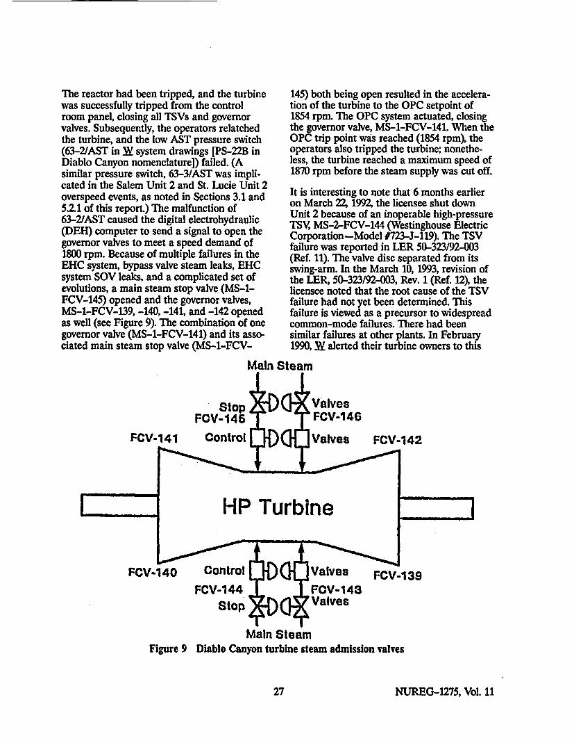
The reactor had been tripped, and the turbinewas successfully tripped from the controlroom panel, closing all TSVs and governorvalves. Subsequently, the operators relatchedthe turbine, and the low AST pressure switch(63-2/AST in 3Y system drawings [PS-22B inDiablo Canyon nomenclature]) failed. (Asimilar pressure switch, 63-3/AST was impli-cated in the Salem Unit 2 and St. Lucie Unit 2overspeed events, as noted in Sections 3.1 and5.2.1 of this report.) The malfunction of63-2/AST caused the digital electrohydraulic(DEH) computer to send a signal to open thegovernor valves to meet a speed demand of1800 rpm. Because of multiple failures in theEHC system, bypass valve steam leaks, EHCsystem SOV leaks, and a complicated set ofevolutions, a main steam stop valve (MS-1-FCV-145) opened and the governor valves,MS-1-FCV-139, -140, -141, and -142 openedas well (see Figure 9). The combination of onegovernor valve (MS-1-FCV-141) and its asso-ciated main steam stop valve (MS-1-FCV-
145) both being open resulted in the accelera-tion of the turbine to the OPC setpoint of1854 rpm. The OPC system actuated, closingthe governor valve, MS-1-FCV-141. When theOPC trip point was reached (1854 rpm), theoperators also tripped the turbine; nonethe-less, the turbine reached a maximum speed of1870 rpm before the steam supply was cut off.
It is interesting to note that 6 months earlieron March 22, 1992, the licensee shut downUnit 2 because of an inoperable high-pressureTSV, MS-2-FCV-144 (Westinghouse ElectricCorporation-Model #723-J-119). The TSVfailure was reported in LER 50-323/92-003(Ref. 11). The valve disc separated from itsswing-arm. In the March 10, 1993, revision ofthe LER, 50-323/92-003, Rev. 1 (Ref. 12), thelicensee noted that the root cause of the TSVfailure had not yet been determined. Thisfailure is viewed as a precursor to widespreadcommon-mode failures. There had beensimilar failures at other plants. In February1990, 3Y alerted their turbine owners to this
Main Steam
StopFCV-145
FCV-141 Control
ValvesFCV-146
Valves FCV-142
HP Turbine
FCV-140 ControlFCV-144
FCV-139
Stop
Main SteamFigure 9 Diablo Canyon turbine steam admission valves
27 NUREG-1275, Vol. 11
type of problem (Operations & MaintenanceMemo 108, which is reprinted in Appendix Fof this report, courtesy of _W Power Genera-tion Business Unit). This issue is an extremelyimportant one because, as the licenseenotedin the LER, "FCV-144 protects the HPturbine (SB) (TRB) from overspeed if theassociated turbine governor valve (SB) (FCV)downstream of FCV-144 should fail to closewhen the overspeed trip or the normal tripmechanism operates." The licensee noted that,during the spring 1993 outage, the licensee'sinspection found other main steam stop valveswhich appeared to have signs of degradationin areas where FCV-144 had failedpreviously.11
The September 12, 1992, overspeed confirmedthat all governor valves opening is a credibleevent. The similarity with the Salem Unit 2overspeed event of November 9, 1991, is ratherstriking; in both cases, the governor valvesopened or reopened as a result of a failedAST pressure switch 63/AST Another im-portant data point derives from the data onturbine control system failure rates in Wreports WCAP-11525lla and WCAP-11529(Ref. 13). Those reports are probabilistic anal-yses that were submitted to the NRC in 1987to support W turbine owners' requests toextend the turbine surveillance testing inter-vals. The failure rates given in WCAP-1152511a for the 63/AST pressure switches arehigher than the failure rates of all otherturbine control system components listed inthat report. The author of this report is notaware of any guidance provided by W to theW turbine owners for preventive maintenanceor change-out of the 63/AST pressureswitches. W guidance for maintenance ofthese pressure switches is limited to onlycalibrating them as noted in the recentlyprovided guidance of CAL 92-02 and AIB9301 (Appendices C and D of this report).Not surprisingly, Diablo Canyon's lessons-learned review of the Salem overspeed
"•blephone discussion, C. R Rhodes, PG&E, and H. LOrnstein, NRC, May 4, 1993.
llaWestinghouse Electric Corporation, (Westinghouse Propri-etay, Clas 2) Report WCAP-11525, "Probabilbtic Evalu-ation of Reduction in Turbine Valve lbst Frequency," June1987.
event1lb revealed that the AST pressureswitch that failed at Diablo Canyon onSeptember 12, 1992, did not fall under anypreventive maintenance program. Preventivemaintenance at Salem Units 1 and 2, BeaverValley Units 1 and 2, St. Lucie Units 1 and 2,Waterford Unit 3, and other plants wassimilarly deficient.
5.1.2 Diablo Canyon Unit 2 Test HandleTrip (January 30, 1993)
On January 28, 1993, the author of this reportvisited Diablo Canyon to review turbine over-speed issues and turbine building hazards.While in the turbine building, the authormentioned to the Diablo Canyon staff that theDiablo Canyon front standard panel wasessentially the same as that of Salem Unit 2 atthe time of the overspeed event. The authortold the Diablo Canyon staff that the SalemSERT report indicated that the team had notruled out the possibility that the operator atthe front standard panel had inadvertentlycaused the trip by moving the test lever veryslightly (about an inch). He also noted thehuman factors enhancements that Salem hadmade after the overspeed event, particularlyplacement of a stationary handle on the frontstandard. The photographs in Figure 10 showthe original front standard panel and themodified front standard panel at SalemUnit 2. The new stationary handle in Fig-ure 10 would prevent an inadvertent trip fromoperator fatigue during turbine testing (seeSection 3.4.6). Although NRC and industryreports have been written on the Salemoverspeed event, information on this par-ticular human factors enhancement has notbeen disseminated to industry in any NRC orindustry report. The author discussed thisenhancement with the Diablo Canyon staffduring his visit to the plant. TWo days afterthe author's visit to Diablo Canyon, DiabloCanyon Unit 2 was testing the loss of con-denser vacuum turbine trip signal, when theoperator who was holding the test lever movedit slightly, causing a turbine trip and a reactortrip from 100 percent power (Ref. 14).
Inbj. Hinds, PG&E, memorandum to M. Angus and T Grebel,May 5, 1992.
NUREG-1275, Vol. 11 28
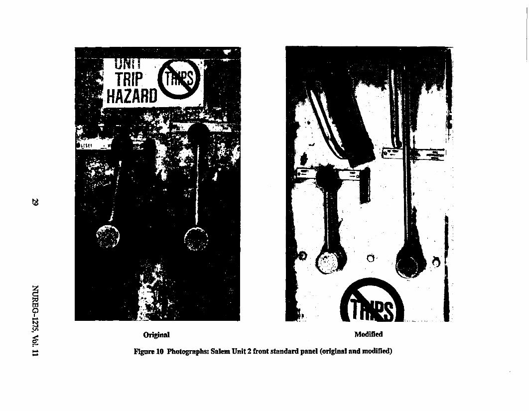
Original Modified
Figure 10 Photographs: Salem Unit 2 front standard panel (original and modified)

During the spring 1993 outage, Diablo CanyonUnit 2 installed a stationary handle on thefront standard similar to the one that was in-stalled at Salem Unit 2 (as shown in Fig-ure 10). In a May 4, 1993, telephone conversa-tion , the author learned that the licensee wasplanning to install a stationary handle on theUnit 1 front standard during the next refuelingoutage.
5.2 St. Lucie Unit 2
5.2.1 St. Lucie Unit 2 Thrbine OverspeedEvent (April 21, 1992)
St. Lucie Unit 2 is an 839 MWe CE PWR witha _W turbine and generator. On April 21, 1992,after a record 502-day run, St. Lucie Unit 2had a manual reactor scram from 12 percentpower. The manual reactor scram should haveenergized the ET-20 SOV and 20 ASTsolenoid resulting in draining of EH fluid,closing of the steam admission valves, andtripping of the main turbine. The turbine didnot trip. Within 2 seconds of tripping thereactor, a reactor operator pressed the turbinetrip button in the control room. The turbinedid not trip. Several additional attempts weremade to trip the turbine using the controlroom push button, but such actions were in-effective. Approximately 1 minute later, thereactor operator opened the generator outputbreakers and closed the main steam isolationvalves. Approximately 3 minutes after thereactor scram, a nuclear watch engineertripped the turbine from the front standard byusing the emergency trip lever (Ref. 15). Be-cause the generator output breakers wereopen before the steam supply was shut off, theturbine oversped to 1850 rpm (rated speed is1800 rpm)'2a. Since the overspeed protectionsystem was set to actuate at 1854 rpm or3 percent overspeed, the overspeed protectionsystem was not challenged during this event.
However, by opening the output breakersbefore confirming that the turbine had
12 Iblephone discussion, C. P. Rhodes, PG&Z, and H. LOrastein, NRC, May 4, 1993.
128D. A. Sager, FPL, memorandum to NRC, "St Lucia Unit 2,Docket No, 50-389, Event Date April 21, 1992, "IlrbineTrip Failure Update," DAS/PSL #697-92, May 14,1992.
tripped, the operator had increased thepotential for a turbine overspeed event.13
The licensee took aggressive action to find theroot cause of the problem and fix it. Thelicensee assembled a large multidisciplineinvestigation team augmented by W fieldservice.
Initial troubleshooting found that the ET-20SOV had failed to shift position when itreceived a valid electrical signal. In addition,the 62/AST-X relay was found to have a looseconnection on one pin (pin no. 6). Pin no. 6 isin the direct circuit for all 20/AST trip signals,including the control room trip manual pushbutton, generator lockout, DEH turbinecontrol system, dc power failure, decreasingAST pressure, steam generator hi-hi level, lowsteam flow anti-motoring trip, and 108 percentelectrical overspeed trip.
The investigation team also found relay62/AST-X had burned contacts.
Either of these two 62/AST-X relay problemsby themselves could have been responsible forfailure of the turbine to trip when the manualtrip push button was pressed in the controlroom.
The licensee acknowledged13a that the62/AST-X relay failures could not have beendetected by St. Lucie's surveillance program.As a result of the St. Lucie overspeed event,the licensee examined the possibility of testingthe control room manual turbine trip pushbutton, the 62/AST-X relay, and the 20/ASTSOV In an April 29, 1993, telephone discus-sion 14, licensee engineers indicated that hard-ware modifications and changes to surveil-lance testing procedures are being and havebeen made to enable surveillance testing ofthis equipment while the plant is operating.The licensee staff also noted that they had
1'The licensee's LER on this event (Ref. 15) focused on whythe reactor tripped and why the turbine failed to trip. TheLER did not mention that the turbine did overspeed to1850 rpm.
138D. A. Sager, FPL, memorandum to NRC, "St. Lucie Unit 2,Docket No. 50-389, Event Date April 21, 1992, 'lbrbine'rip Failure Update," DAS/PSL #697-92, May 14, 1992.
1 Ielephone discussion M Little and L Batach, FPL, andH. L Ornstein, NRC, April 29,1993.
NUREG-1275, Vol. 11 30

considered installing a redundant ASTsolenoid as had been recommended in WCAL 92-02 and AIB 9301 (Appendices C andD of this report), but concluded that theredundant 20/AST was unnecessary in view ofthe other improvements being made, such asmonthly testing of the 20/AST coil and theinstallation of a turbine trip SOV test andmaintenance block to allow individual testingof the ET-20, OPC 20-1, and OPC 20-2 SOVswhile the plant is on line. (The SOV test andmaintenance block is discussed below.)
As part of its investigation, the licensee sentthe ET-20, OPC 20-1, and OPC 20-2 SOVs toan independent laboratory. Those SOVs werethe same type as the ones that had failed atSalem Unit 2 in November 1991. The inde-pendent laboratory, Main Line EngineeringAssociates of Exton, PA (MLEA), which per-formed the investigations of the three ParkerHannifin SOVs that were removed from St.Lucie Unit 2's EHC system, had performedsimilar investigations on the Salem Unit 2SOVs.
Even though St. Lucie appeared to be doing areasonably good job of maintaining the EHCfluid cleanliness and had replaced the SOVsbefore the record 502-day cycle, the laboratoryfound that ET-20 had stuck because particu-late matter was blocking ports inside thevalve.
The particulate matter, which was classified as"dirt," consisted of fused plastic, weld slag,organic fibers, sand, clay, and rust 14a. Thesource of the dirt was indeterminate. The flowof the Fyrquel hydraulic fluid through theSOV pilot ports "...was either blocked orsufficiently occluded by the 'dirt' to substan-tially reduce the flow of hydraulic oil so thatthe main valve would not open" to dump theEHC fluid to initiate the closing of the steamadmission valves. MLEA found some rustparticles in the ET-20 SOV's pilot body andon the pilot spool; however, those particles did
1"&Main Line Engineering Associates Test Report, "RootCause Failure Investigation for Parker-Hannifin SolenoidOperated Valves Removed From the EHC System of the St.Lucie Station Westinghouse lurbine," M9000-TRO4,June 5, 1992.
not interfere with pilot spool motion. LikeET-20, OPC 20-1 and OPC 20-2 were foundto have some rust particles which did notaffect valve operation. However, unlike ET-20,the OPCs did not have any dirt buildup. TheOPCs' internal ports were unrestricted allow-ing hydraulic fluid to drain freely whenenergized. MLEA indicated that the OPCswere fully operable and did not have symp-toms of incipient failure. However, MLEA didnote hard, tenacious corrosion deposits on thepoppets inside ET-20 and both OPC 20SOVs 1 '4a,1. The deposits are typical of hydro-lyzed Fyrquel and indicate the presence ofwater. Another important observation notedin the laboratory report is the fact that theParker Hannifin SOVs have extremely tightclearances and therefore can be very unforgiv-ing with regard to contaminants.
The laboratory report highlights theunforgiving aspects of the EHC system andemphasizes the absolute necessity formaintaining EHC system quality. It wasparticularly concerned that particulates ofundetermined origin were present in theET-20 SOV and that products of Fyrquelhydrolysis were present in the SOVs eventhough
(1) the ET-20, OPC 20-1 and OPC 20-2SOVs were in service for only one fuelcycle (extended as it may have been to arecord 502 days)
(2) the licensee has performed EHC fluidflushing during each refueling outage
(3) the licensee had maintained the hydraulicfluid in a manner which met or exceededW's recommendations
The author's discussions with licensee engi-neers during his site visit at the licensee'srequest during the root cause investigationrevealed that the dirt and moisture in theParker Hannifin valves were quite likelycaused by fine particles from new EHCsystem filters, Solexsorb filters, which hadmalfunctioned and had to be replaced with
Llrlephone discussion, J. Murphy, MI.EA, and H. LOrnstein, NRC, April 30, 1993.
31 NUREG-1275, Vol. 11
the original type (fullers earth filters). The newSolexsorb filters had been installed to reducemoisture, apparently because of previousmoisture problems with the EHC fluid.
After the root cause investigation was con-cluded, the licensee implemented many hard-ware, procedural, and training improvements.Some of the most noteworthy modificationsand changes made or being made at St. LucieUnits 1 and 2 as a result of the April 21, 1992,overspeed event at Unit 2 are listed below-
* Modified the procedures and conductedappropriate training to emphasize thenecessity of confirming that the mainturbine has tripped before opening thegenerator output breakers.
* Installed a "turbine trip solenoid valvemaintenance-test block" and key switchesto enable operators to test the ET-20,OPC 20-1, and OPC 20-2 SOVsindependently while the plant is on line.
Installed continuously energized monitor-ing lights for 20/AST and ET-20, OPC20-1, and OPC 20-2 to verify circuitcontinuity.
Installed a key switch on the governorpedestal to allow monthly testing of20/AST via the 62/AST-X contacts.
Added a coalescing filter cartridge to theEHC system to further reduce moisturein the EHC Fyrquel system.
The licensee also pursued the issue of replac-ing the carbon steel Parker Hannifin SOVs(ET-20, OPC 20-1, and OPC 20-2) withstainless steel SOVs. W is making such SOVsavailable. (See Section 4.3 of this report for adiscussion of this modification and W's otherrecommendations.)
5.2.2 St. Lucie Unit 2 Spurious ThrbineTrip During Solenoid-OperatedValve Testing (July 10, 1992)
As noted above, because of the April 21, 1992,turbine overspeed event, the licensee installed
a turbine trip solenoid valve maintenance-testblock to enable operators to test the ET-20,OPC 20-1, and OPC 20-2 SOVs independ-ently while the plant is on line. The licenseedesigned the test and maintenance block. Whad been consulted during the block's designprocess.
The test and maintenance block was testedsuccessfully before plant restart. However, onJuly 10, 1992, while the plant was on line, thelicensee used the test and maintenance blockto test ET-20 SOV and, contrary to thedesign, the testing resulted in a reactor scram.The closing of the ET-20 outlet isolation valvefollowed by the successful opening of ET-20caused a rapid (20 millisecond) pressure decaythat was interpreted by the RPS as a loss ofload. The licensee noted (Ref. 16) that thetransient and the resulting reactor scram wereunexpected. The modification had been testedbefore startup; however, because the RPSpressure switches are not activated until thereactor reaches 15 percent power, thepreoperational testing did not provide awarning of the unexpected EHC fluid pressurespike.
As a result of the July 10, 1992, reactor scram,the licensee suspended the EHC SOV monthlytesting until a reliable on-line testing methodcould be developed. Subsequently, the licenseeredesigned the test and maintenance block toeliminate the pressure pulse (see Figure 11).The modified test and maintenance blockisolates trip functions from the SOV beingtested but remains available for the other twoSOVs, introducing an alternate supply ofEHC fluid from the EHC supply header. Thealternate fluid supply eliminates the possibilityof feedback to the emergency trip header onthe RPS, thereby eliminating the possibility ofcausing an unwarranted reactor scram. Tominimize human errors, the SOV testingrequires the use of key switches. The revisedtest and maintenance block was tested ex-tensively at Florida Power and Light Com-pany's (FPL's) Manatee fossil plant. In April
NUREG-1275, Vol. 11 32

CLOSING INLET ISOLATION VALVE ALLOWS TESTING OF ASSOCIATED SOLENOID VALVE.CLOSING BOTH INLET AND OUITLET ISOLATION VALVES ALLOWS ASSOCIATED SOLENOIDVALVE REPLACEMENT WITH SYSTEM IN OPERATION.
TRIP FLUIDFROM TV & RHSTOP VALVES
TODWAIN
NEW PIPING• 3 EXASTING BLOCK PIPING
t=3 MAINTEST BLOCKFROM DEH CONDiTIONINGFLTER SUPPLY HDR.
• II |
Figure 11 St. Lucie block for testing EHC system SOVs independently
33 NUREG-1275, Vol. 11

199316, the revised test and maintenance blockwas being installed on Unit 1, with Unit 2installation to be done later (with no on-lineEHC system SOV testing to be performed onUnit 2 until after the installation).
5.3 Big Rock PointBig Rock Point is a 69 MWe BWR with aturbine unique among other U.S. LWRs. Theturbine operates at 3600 rpm and was built bythe GE, Lynn, MA division. GE's Lynn, MAdivision no longer makes steam turbines, andno other similar turbines are in service at U.S.nuclear plants. Nonetheless, the failures in theturbine control system at Big Rock Point arevery enlightening, and they provide lessons tobe learned.
5.3.1 Big Rock Point Common-ModeBypass Valve Failures
On October 27, 1989, the licensee observedcommon-mode failures of the turbine bypassvalve (failed to open on an open signal and onOctober 31, 1989, the turbine bypass isolationvalve failed to stroke during a test [Ref. 17]).The cause of those two failures was thelicensee's use of Garlock 938 packing to re-pack the valves during turbine maintenance.Garlock 938 is a compression packing manu-factured from aluminum tinsel treated withnatural rubber cement and die formed, thentreated with zinc. The packing hardened andwas bound to the valve stems, preventing theiroperation. At atmospheric conditions, Garlock938 is flexible and easy to install. However, itbecomes hard and brittle when subjected toheat and pressure. At Big Rock Point, theGarlock 938 became a tenacious ceramic-likematerial shortly after being subjected to hightemperatures and pressures. The Garlock 938was installed during an outage. The problemwas found during power escalation while theplant was at 31 percent power. Conventionalmethods for removing the hardened Garlock938 were unsuccessful. Eventually, it wasremoved by drilling and using a chisel-anoperation that took 3-1V2 days to complete.
16U'lephone discussion, L Batsch and M. Little, FPL, andHLOrnstein, NRC, April 29, 1993.
After the problem with the turbine bypassisolation valves was discovered, the plant wasshut down on November 1, 1989, so that otheýývalves with Garlock 938 packing could be 'examined. Garlock 938 was also used on twomotor-operated valves (MOVs) in the corespray system. Examination of the valves in thecore spray system found the packing hard-ened, but the valves still able to function. Itwas not clear how much longer the Garlock938 would have had to harden to cause theMOVs to be unable to stroke. The licenseenoted (Ref. 17) that, after the failures, Garlockrepresentatives still supported the use ofGarlock 938 as an acceptable spacer material.The licensee also noted that Garlock 938 hadbeen used for 40 years as a "severe use" pack-ing and had also been used as a spacer at BigRock Point from 1987 to 1989. At a recentAir-Operated Valve Users Group Meeting' 7,the author learned that Garlock Corporationperformed extensive laboratory analyses onthe hardened Garlock 938, but was unable toconclusively determine the cause of thefailures that had occurred at Big Rock Point.
53.2 Big Rock Point Repetitive Failuresof the Thrbine Trip System
On June 3, 1992, August 24, 1992, October 5,1992, and February 28, 1993 (Refs. 18 through21) and August 30, 19 9217a, the turbine failedto trip on demand because the hand-tripsolenoid (HITS) failed. The HTS' function is toautomatically close the TSV on a reactorscram. The HTS is actuated automatically byautomatic trip signals and can be actuatedmanually by a push button on a control roompanel. The licensee noted17b there had been'eight failures of the HITS before 1992. (See"lble 6.)
On June 3, 1992, the turbine failed to auto-matically trip on a reactor scram (Ref. 18).
17Discussion, H. L Ornstein, NRC, and B. D. Crocker,Garlock, Inc., June 3, 1993.
17sConsumers Power Company, Deviation Report D-BRP-92-065, "Failure of 1iarbine HIS to hTip," September 2,1992.
l7bConsumers Power Company, Deviation Report D-BRP-92-071, "Failure of lMrbine Stop Valve (CV-4200) lbClose," October 8, 1992.
NUREG-1275, Vol. 11 34

Table 6 Big Rock Point failure to trip history* before 1992
DATE EVENT
04/06n8 The turbine failed to trip from loss of load. Manually tripped stop valve. Replacedcoil.
12/31/84 CV-4200 failed to close on signal from push button, tripped from front standard.
The trip coil was found to have an open winding. Upon inspection, it showed fourscore marks corresponding to the location of the mounting screws. Coil replaced.
04/05/85 While shutting down the plant, the turbine stop valve failed to close. Push buttonand X-phase failed. Manually tripped from front standard.
The 125 V dc solenoid was found energized and the trip mechanism still latched.A significant amount of additional force was required to assist the solenoid to tripthe handle latch. Mechanically, there seemed to be a misalignment of the solenoid(85-MSS-0019).
02/11186 Push button and Y-phase failed to trip turbine during shutdown. Turbine trippedfrom the front standard.
The solenoid was energized during both push button and Y-phase attempts. Thetoggle links were still in locked position. The force exerted by the energized coilwas not sufficient to overcome the friction in the mechanical I links(86-MSS-O011).
07/01/86 Turbine failed to trip after reactor scram. Push button failed, tripped at frontstandard.
Root cause determined to be worn mechanical links and also out of adjustment.New trip device was installed during 1987 refueling outage (87-TGS-007).
04/08/88 During plant shutdown, the turbine trip failed from the push button, and theZ-phase contacts. This resulted in a 116 OCB trip, but the stop valve failed toclose. Subsequently closed from the front standard.
(1) Broken lead to the solenoid coil, (2) broken wire strands at crimped wire lugs,(3) aged wires in front standard, (4) broken wire at connection to the arcsuppression capacitor.
07/01/88 During S/D, the HTS did not function properly. HTS would not trip and thecontinuity light was out.
Bad wiring connection. Installed indicating light in control circuitry. Replaced coil,armature and solenoid link stud mechanism, also the stud spring was locked to aposition causing the solenoid link bar to twist the toggle links and latch.
07/18/90 During S/D, the HTS did not trip when manual turbine trip push button wasdepressed.iHpped using front standard.
Wear in mechanical linkage parts caused misadjustment of solenoid trip latchcausing linkage binding to the point that the solenoid could not pull up the linkageto release the trip latch.
*Direct quotes from Consumers Power Company, Deviation Report D-BRP-92-071, "Failure of Turbine Stop Valve (CV-4200) ToClose," October 8, 1992.
35 NUREG-1275, Vol. 11

Operator attempts to manually trip the tur-bine using the push button on a control roompanel also failed. Subsequent examination ofthe plant data determined that the HTS hadreceived demand signals and that the HTShad failed. Approximately 1 minute after thereactor scrammed, a control room operatorfound that the generator output breakers werestill closed. He opened the output breakersand found that the turbine had not tripped;the stop valve was still open. He pushed theHTS manual trip button in the control room.When the push button was found to be in-effective, an auxiliary operator was dispatchedto the turbine's front standard. Using a handtrip lever, the auxiliary operator successfullytripped the turbine. Four minutes elapsedfrom the reactor scram until the turbine wassuccessfully tripped. The turbine had thepotential to overspeed from the time the out-put breakers were opened until the turbinewas tripped (3 minutes). However, because thesteam admission valves were closing in re-sponse to the original transient1, the turbinedid not overspeed.
After plant shutdown, the licensee's root causeinvestigation of the event determined that theHTS (manufactured by Ruggles-Klingmann)had mechanically bound. The licensee dis-assembled, inspected, readjusted, and success-fully tested the HTS.
On August 24, 1992, the HTS again failed toactuate on demand (Ref. 19). The plant was inhot standby and the licensee was performing apre-turbine startup checkout. The actuationsignal to the HTS was manually initiated fromthe control room panel. The HTS manufac-turer's representative examined the failedHTS. He noted that the mechanical linkages(see Figure 12), which were set in accordancewith the plant's maintenance instructions, didnot meet manufacturer's recommendations. Itwas suspected that the improper setting hadcaused the mechanical binding.
When electrical tape from the HTS was re-moved, a terminal lug fell off. The licensee
ISReactor scram on high flux because of a sudden spike inreactor pressure when the initial pressure regulator systemfailed.
could not determine if the lug had contributedto the failure. The HTS was replaced with anew one which was provided by the manufac-turer's representative. As a result of thisexperience, the licensee planned to have theHTS manufacturer's representatives performfuture adjustments.
On October 5, 1992, during a plant shutdown,control room operators were unable to trip theturbine using the control room push button toactuate the HTS (Ref. 20). The generator fieldbreaker opened but the TSV did not trip.Again, the turbine was tripped manually withthe hand trip lever at the front standard.
The manufacturer was contacted about thefailure. It was believed that the HTS had ex-perienced a hydraulic locking. Although therewere traces of oil leaking from the stem andbushing interface of the HTS, the leak was notbelieved to be the cause of the malfunction.The licensee also verified that the hydraulic oilwas clean.and the failure was not caused bycontaminants or particulates in the oil. Thelicensee changed out parts of the hydraulicsystem to provide less chance for hydrauliclocking. In addition, the HTS body wasreplaced. However, the SOV plunger shaft wasreused. In order to help keep the HTS SOV'spiston assembly from sticking, the licenseeincreased the HTS spring tension.
On February 28, 1993, while shutting down theplant, the HTS failed again and the turbinewas again shut down with the hand trip leverat the front standard (Ref. 21). The licensee'sroot cause failure analysis found that wear onthe internal parts of the solenoid was causingthe plunger to hang up. The licensee noted ina March 3, 1993, conference call with the NRCthat after the October 1992 failure, the "topworks assembly on the HTS had been re-placed, but that the solenoid and shaft hadnot been replaced." Furthermore, the licenseenoted that even though the SOV had failedseveral times before, the SOV's internals hadnever been inspected for wear until Febru-ary 28, 1993. The licensee's staff noted thatthey were pursuing two possible corrective
NUREG-1275, Vol. 11 36
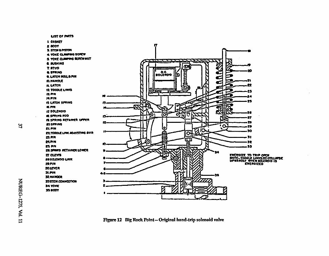
IUST of PAMTI 0*gSgi2 MOTa sTEMS ISTONs4 Ica( Oa"'G ScwWa Tm~ CAMP" "LrEWMira SMINGn2 STuoa Spon'sS EATCVIROL&PIWn"ftmAWIn. LATCIIIt Too= SIVINSno"PI14FIN
I? 9OLCROIDasPNWS oDmS snpins OETAINER IPrmInsPmiNft pin521001.1 u'm ADRISTV00 *A*211P111ftPIRn Plft98 WVM RETAWN~ LOWERV CLEM'E.a~ff LOW
22PIN313UWER31.101"mnZwA"=339MMUMN00rnoi54 TooE359OU?
tNwOITE TO I~COTE- TOGGLE =~l n02)CO-J.WXUPAROi.Y Vffll SvOWWO IS
(NE OtTED6
NC)
LA
0
Figure 12 Big Rock Point- Original hand-trip solenoid valve
actions. For the short term, depending on theschedule, the licensee would either replace theHTS with a refurbished one or replace theHTS with another valve of a simpler typebefore power ascension (see Figure 13). Forthe long term, the licensee considered modify-ing the manifold block that housed the HTSto allow another valve to be added in parallelto the HTS. The extra valve would precludeanother HTS failure from tripping the turbine.
5.3.3 Big Rock Point Long-TermUnavailability of EmergencyGovernor Exerciser
The emergency governor exerciser (EGE) is abackup overspeed trip that is integrated intothe turbine control system. It is designed totrip the turbine if a condition requiring aturbine trip occurs while the plant is on lineand the turbine's overspeed protection systemis being tested. (During testing, the turbine'soverspeed protection system is bypassed.)
In Inspection Report 50-155/92-020 (Ref. 19),NRC inspectors noted that the licensee per-formed a special test of the EGE indicatinglights which were not reparable during theAugust 1992 outage. The inspectors also notedthat the EGE has not been operable and hasnot been used for several years. Consequently,for several years, the licensee has not testedthe overspeed protection system while theplant was at power. GE strongly recommendsthat for the 1800 rpm turbines, the overspeedcontrol systems be periodically tested duringpower operation (see Section 4.4). The3600 rpm Big Rock Point main turbine has abackup overspeed device (the EGE), which, ifoperable, would provide protection duringperiodic tests of the TOPS during poweroperation.
5.4 Palisades Common-ModeFailure of Six Steam AdmissionValves
The Palisades plant has one 730 MWe CEreactor with a _W turbine and generator. OnSeptember 20, 1992, during startup testing, theplant performed a trip test of the main tur-bine. Six of 16 quick-acting steam admission
valves, four intercept valves, and two reheatstop valves performed sluggishly. The valves,which are supposed to close within 1 sec-ondiSa, took almost 2 minutes to close. Themanagement at both Palisades and W turbinedivision were sensitive to the problem. Thelicensee's position was that the plant wouldnot be restarted until the problem was fixed.The licensee initiated an aggressive programto determine the root cause of the problemand followed up by taking prompt correctiveaction.
The problem was suspected to be caused byflow anomalies in the EHC system or possiblymalfunctions of the DEH control systemcomputer or its software.
Initial troubleshooting pointed toward "toomuch flow" in the trip header or possibly arestriction in a drain line. There was concernthat the ET-20 might have stuck in anintermediate position.
In addition to the R site representatives, sev-eral 3N field service engineers were dispatchedto the site. Subsequently, _W brought specialequipment 19 to the plant to measure EHCsystem flows and measure system pressures.Assistance was also provided by W personnelat W turbine division headquarters (Orlando,FL). _W personnel performed computer simu-lator analyses of the Palisades turbine's con-trol system. On September 23, 1992, the Wsite representative stated that overall about150 people for the licensee and 3Y were work-ing on the problem, including 20 engineers pershift plus 4 engineers at Orlando20.
The W site representative noted that the EHCsystem had been reasonably well maintainedat Palisades. The system was clean. It hadbeen flushed in March 1992, and the ET-20and 20/AG SOVs (equivalent to OPC 20) had
1'8a Palmisano, Consumers Power Company Employee Com-munication, memorandum, 'Drbine Outage Update,"October 1, 199Z
196 ft x 8 ft x 8 ft EHC system flow analyzer.2•slephone discussion, R. Hunneke, Westinghouse Palisades
Site Representative, and H. LOrnstein, NIRC, Septem-ber 23, 1992.
NUREG-1275, Vol. 11 38

• '1 Name of Part
1 Body
2 Stem
3 Piston
4 Spring
6 Spring Retainr Et Pin
6 Piston Shaft Tube
7 Piston Shaft "0" Ring
8 Stem Guide Bushing
9 Stem Guide Bushing "0" Ring
10 Stem Gulde Bushing Screws
24 Solenoid Assembly
:3 Solenoid Housing Gasket
34 Soleno~d Housing Capscrew37 Adapter
38 Adapter "0" Ring39 Adapter Capsorew
40 Adapter Capscrew
Adapter Proetor
Figure 13 Big Rock Point--Replacement hand-trip solenoid valve
39 NUREG-1275, Vol. 11

been refurbished by the manufacturer, ParkerHannifin. However, about 3 weeks before theevent, the EHC system developed a leak andlost about 50 gallons of fluid. In addition, anSOV in the reheat stop valve controls failed.
The troubleshooting found EHC flow distri-bution anomalies, but did not find any spe-cific component problem. On the basis of thetesting and computer analyses, more EHCfluid drain lines and orifice plates were addedto enhance turbine control valve operation.Postmaintenance testing demonstrated sig-nificant improvement in the performance ofthe valves that had exhibited sluggishbehavior. The repairs were completed onSeptember 27, 1992, and the plant came online the next day.
In a communication to station employees2°a,the plant outage manager noted the positiveaspects of how the turbine problems werehandled. He noted that the turbine testing wasdesigned "to verify that important turbinesystems are operational and the testing dididentify the problem." Furthermore, he notedthat it was fortunate that the problem wascorrected before the plant was on line. "If theproblem had occurred and been undetected,we could have had a turbine overspeed on asubsequent trip."
5.5 Comanche Peak Unit 1Inadequate Followup to TurbineOverspeed Protection SystemTest Failure (May 16, 1992)
On May 16, 1992, while the reactor was at 100percent power, the licensee was performingTOPS testing with the ATI (see Section 4.7for additional information on the ATr). TheATI indicated six faults emanating primarilyfrom pressure and vacuum switches. Thelicensee concluded that there was a problemwith the AT. 21 Since surveillance testingcould not be completed with the AIT, TOPSsurveillance testing was then performed satis-
OT Palmisano, Consumers Power Company Employee Com-munication, memorandum, ruIrbine Outage Update,"October 1, 1992.
21Form STA 515-1 regarding May 16, 1992, event recorded asLER 445/92-021 (Ref. 22).
factorily in the manual mode. Two weeks lateron May 30, 1992 (as required by TS), thelicensee again tried to perform the TOPS sur-veillance testing with the ATI1 and the samesix faults were indicated again. The TOPSsurveillance tests were then conducted satis-factorily in the manual mode. As noted in aletter from Siemens2la and Section 4.7 of thisreport, manual testing of the TOPS bypassesthe TOPS and puts the responsibility foravoiding a destructive overspeed solely on theoperator.
On June 3, 1992, the plant experienced ascram which was unrelated to the turbinesystems. During the outage, turbine controlsystem troubleshooting found the problem tobe not the vacuum switch, but a loose wire inthe turbine-generator control cabinet. A sec-ond loose wire was found in the turbine-generator control cabinet (Ref. 22). After theterminals were tightened, the vacuum switchand the ATIr worked satisfactorily.
Three months later, on September 11, 1992, asystems engineer determined that one of theloose wires on the turbine-generator controlcabinet had disabled one train of the P-4interlock actuation relay (which trips theturbine on a reactor scram) and the sametrain of the P-14 interlock actuation relay(which trips the turbine on high steam gener-ator level). The disabled P4 and P-14 inter-lock actuation relays are listed in the ESFAStables of the Comanche Peak TSs as havingallowable outage times of 48 and 12 hours,respectively.
Although the manufacturer's assessment ofthe Comanche Peak TOPS indicates that adestructive overspeed is unlikely, failure of theoperators at Comanche Peak (as at Salem) toimmediately determine the root cause of aTOPS testing anomaly placed the plant in avulnerable position, bypassing the TOPSleaving only manual action available to pre-vent a destructive overspeed.
In response to AEOD questions about whichequipment was affected by the second looseterminal, the licensee traced the wiring. In a21
27- Racie, Siemens Power Corporation, letter to R. T Jenkins,T U. Electric, March 19,1992.
NUREG-1275, Vol. 11 40

May 27, 1993, telephone discussion2, thelicensee informed AEOD that the secondloose wire in the turbine control cabinetaffected one train (train A) of the generatorlockout relay. This relay sends a trip signal tothe turbine control system when the generatoroutput is disconnected from the grid. (Failureto trip the main turbine when the generator isdisconnected from the grid could lead to anoverspeed condition.)
It is also important to note that the looseterminals on the turbine-generator controlcabinet were essentially degradations ofESFAS. Although the loose terminal, whichwas discussed in an LER (Ref. 22), onlyaffected the A train, the LER also noted thatthere was another loose wire in the samecabinet. In the LER, the licensee noted thatcause of the loose wiring was unknown, andthat it was a generic concern. Furthermore,the licensee noted 22a that the loose wire caus-ing the inoperable main turbine trip event"could have been a precursor to a criticallyconsequential event."
6 FINDINGS
6.1 Complacency Toward TurbineOverspeed
Until November 9, 1991, the likelihood thatmissiles from a main turbine overspeed eventcould penetrate the turbine casing at a U.S.nuclear plant was considered to be very low:10-4 to 10-5 per turbine-year according toNRC evaluation criteria (Ref. 5) and I105 to10-9 per turbine-year according to manu-facturers' analyses22b,2.
Inherent in these analyses were low estimatesfor main turbine overspeed events which gen-
22Telephone discussion, M. Hanson, Comanche Peak, andH. LOrnstein, NRC, May 27, 1993
22-E U. Electric, STA-515-1, Category Analysis Worksheet,October 21, 1992.
22bGeneral Electric Company, lhrbine Department, "MemoReport--Hypothetical Turbine Missiles-Probability ofOccurrence, March 14, 1973.
22cWestinghouse Electric Corporation, (westinghouse Proprie-tary Class 2) Report wCA-11525, Proba flistic Evaluationof Reduction in'rbne Valve 1Test Frequency," June 1987.
erated missiles. These analyses took credit fordiversity and redundancy in the overspeedprotection systems and did not consider theloss of diversity that may occur when theoverspeed protection devices are disabled fortesting or because of operator error. Theseanalyses also did not assess correctlycommon-mode failures of the overspeedprotection system from contaminated oilsystems or degraded SOVs and did notrecognize that redundancy could be lostbecause surveillance testing practices couldnot detect individual failures of redundantcomponents (SOVs).
It is interesting to note that some turbineoperating manuals did not notify the turbineowners of any specific maintenance orreplacement requirements for the SOVs of theoverspeed protection system. With thepossible exception of steam dump valvefailures, the estimates of the failures of theindividual components assumed independence(no coupling or common-mode contributions).The analyses implicitly assumed that thedegradation or failure of an individual SOVwould be detected and that the SOV would bereplaced or repaired to an as-good-as-newcondition before experiencing a similar failureor degradation of its redundant backup. Thisreport found industry practice to be incon-sistent with many of these assumptions.
6.2 Testing That Defeats DiversityMany plants defeat redundant overspeedprotective devices when testing turbines andTOPS at power. By design, Salem's monthlytesting of the turbine's mechanical protectivedevices required bypassing most of the auto-matic turbine trip features and deactivatingthe turbine's mechanical overspeed trip.During the tests, overspeed protection reliedonly on three SOVs (OPC 20-1, OPC 20-2Zand ET-20).
Until the Salem overspeed event, the concernfor disabling some of the main turbine's pro-tective devices did not appear to be a signifi-cant one. However, the event raised theindustry's awareness of this issue (see Chap-ter 4). Discussion with some utilities indicateda preference for resolving the concern by
41 NUREG-1275, Vol. 11
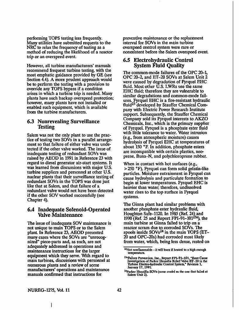
performing TOPS testing less frequently.Many utilities have submitted requests to theNRC to relax the frequency of testing as amethod of reducing the likelihood of a reactortrip or an overspeed event.
However, all turbine manufacturers' manualsrecommend frequent turbine testing, with themost emphatic guidance provided by GE (seeSection 4.4). A more prudent approach wouldbe to perform the testing with a provision tooverride any TOPS bypass if a conditionarises in which a turbine trip is needed. Manyplants have such backup overspeed protection;however, many plants have not installed orenabled such equipment, which is availablefrom the turbine manufacturers.
6.3 Nonrevealing SurveillanceTesting
Salem was not the only plant to use the prac-tice of testing two SOVs in a parallel arrange-ment so that failure of either valve was unde-tected if the other valve worked. The issueofinadequate testing of redundant SOVs wasraised by AEOD in 1991 in Reference 23 withregard to diesel generator air-start systems. Itwas learned from discussions with major U.S.turbine suppliers and personnel at other U.S.nuclear plants that their surveillance testing ofredundant SOVs in the TOPS was done justlike that at Salem, and that failure of aredundant valve would not have been detectedif the other SOV worked successfully (seeChapter 4).
6.4 Inadequate Solenoid-OperatedValve Maintenance
The issue of inadequate SOV maintenance isnot unique to main TOPS or to the Salemplant. In Reference 23, AEOD presentedmany cases where the SOVs are "unrecog-nized" piece-parts and, as such, are notadequately addressed in operations andmaintenance instructions for the largerequipment which they serve. With regard tomain turbines, discussions with personnel atnumerous plants and a review of somemanufacturers' operations and maintenancemanuals confirmed that instructions for
preventive maintenance or the replacementinterval for SOVs in the main turbineoverspeed control system were rare ornonexistent before the Salem overspeed event.
6.5 Electrohydraulic ControlSystem Fluid Quality
The common-mode failures of the OPC 20-1,OPC 20-2, and ET-20 SOVs at Salem Unit 2were caused by degradation of Fyrquel EHCfluid. Most other U.S. LWRs use the sameEHC fluid; therefore they are vulnerable tosimilar degradations and common-mode fail-ures. Fyrquel EHC is a fire-resistant hydraulicfluid23 developed by Stauffer Chemical Com-pany with Electric Power Research Institutesupport. Subsequently, the Stauffer ChemicalCompany sold its Fyrquel interests to AKZOChemicals, Inc., which is the primary supplierof Fyrquel. Fyrquel is a phosphate ester fluidwith little tolerance to water. Water intrusion(e.g., from atmospheric moisture) causeshydrolysis of Fyrquel EHC at temperatures ofabout 150 *F In addition, phosphate estersare incompatible with certain plastics, neo-prene, Buna-N, and polychloroprene rubber.
When in contact with hot surfaces (e.g.,> 250 *F), Fyrquel can form solid gelatin-likeparticles. Moisture entrainment in Fyrquel cancause hydrolysis and particulate formation tobegin at lower temperatures. Fyrquel EHC isheavier than water; therefore, undissolvedwater rises to the top surface in Fyrquelsystems.
The Ginna plant had similar problems withanother phosphate ester hydraulic fluid,Houghton Safe-1120. In 1985 (Ret 24)_and1990 (Ref. 25 and Report FPI-91-101l3a), themain turbine at Ginna failed to trip on areactor scram due to corroded SOVs. Thespools inside SOVs24 in the main TOPS (ET-20 and OPC-20s) had corroded most likelyfrom water, which, being less dense, rested on
23Not nonflammable--it will burn if heated to a high enoughtemperature.
23&Failure Prevention, Inc., Report FPI-91-101, "Roo' CauseInvestigation of Parker Hannifin Relief Valve ET-20 in the"nrbine Electro-hydraulic Control System," Revision 1,January 17, 1991.
24Parker Hannifin SOVs (same model as the one that failed atSalem Unit 2).
NUREG-1275, Vol. 11 42
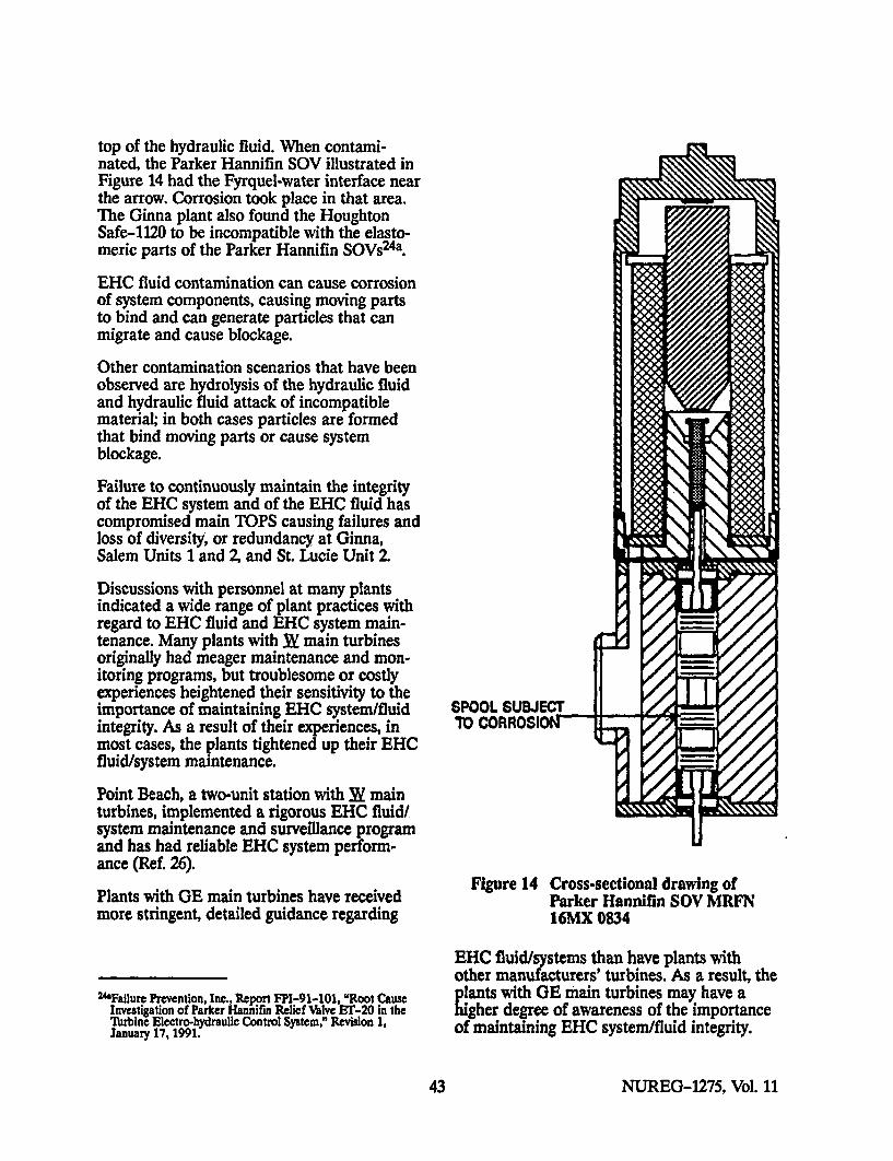
top of the hydraulic fluid. When contami-nated, the Parker Hannifin SOV illustrated inFigure 14 had the Fyrquel-water interface nearthe arrow. Corrosion took place in that area.The Ginna plant also found the HoughtonSafe-1120 to be incompatible with the elasto-meric parts of the Parker Hannifin SOVs24a.
EHC fluid contamination can cause corrosionof system components, causing moving partsto bind and can generate particles that canmigrate and cause blockage.
Other contamination scenarios that have beenobserved are hydrolysis of the hydraulic fluidand hydraulic fluid attack of incompatiblematerial; in both cases particles are formedthat bind moving parts or cause systemblockage.
Failure to continuously maintain the integrityof the EHC system and of the EHC fluid hascompromised main TOPS causing failures andloss of diversity, or redundancy at Ginna,Salem Units 1 and Z and St. Lucie Unit 2.
Discussions with personnel at many plantsindicated a wide range of plant practices withregard to EHC fluid and EHC system main-tenance. Many plants with _W main turbinesoriginally had meager maintenance and mon-itoring programs, but troublesome or costlyexperiences heightened their sensitivity to theimportance of maintaining EHC system/fluid SPOOL SUBJECTintegrity. As a result of their experiences, in TO CORROSION .most cases, the plants tightened up their EHCfluid/system maintenance.
Point Beach, a two-unit station with _W mainturbines, implemented a rigorous EHC fluid/system maintenance and surveillance programand has had reliable EHC system perform-ance (Ref. 26).
Figure 14 Cross-sectional drawing ofPlants with GE main turbines have received Parker Hannifin SOV MRFNmore stringent, detailed guidance regarding 16MX 0834
EHC fluid/systems than have plants withother manufacturers' turbines. As a result, the
24Failure Prevention, Inc., Report FPI-91-101, "Root Cause plants with GE main turbines may have anvesigation of Parker Hannifin Relief Valve ET-20 in the higher degree of awareness of the importance
lbrbine Electro-hydraulic Control System," Revision 1, of maintaining EHC system/fluid integrity.January 17, 1991.
43 NUREG-1275, Vol. 11

However, discussions with turbine engineersduring a visit to a site with GE turbinesrevealed that they were performing minimummaintenance on the EHC system and had notyet observed any problems. It should be notedthat the EHC systems of GE turbines andnewer W systems have certain design featuresthat help retain EHC fluid integrity (e.g., des-iccant air dryers on the air inlet and full-flowfilters that the turbine manufacturer recom-mends be changed out quarterly). The impor-tance of maintaining the EHC system fluid isspelled out very clearly in many operationsmanuals and technical letters that GE hasprovided to the turbine purchasers. Forexample, Technical Information Letter 796-2,circa 1975 24b, states:
The EHC fluid must [sic] be keptfree of both solid particles as well aschemical impurities to insure thefree operation of critical controloverspeed protection devices.
Technical Information Letter 877, circa
197824, states:
EHC Fluid Quality
Fluid quality, which encompassessolid particle cleanliness as well asproper chemical makeup is of utmostimportance. Solid particle contami-nation may lead to one or morecontrol devices malfunctioning. Ineither of these cases, this can lead toa possible overspeed event. This hasbeen previously brought to yourattention in our Technical Informa-tion Letter (TIL) 769, 'EHC FluidSystems Valve Tests' dated March1975 and TIL 796, 'Water Contami-nation of EHC Fluid Through EHCCoolers' dated December 1975.
24bGenrlni Electric, Technical Information Letter 796-2,"Water Contamination of EHC Fluid Through the EHCCoolers," Attachment I.
24General Electric, Technical Information Letter 877, "EHCHydraulic Power Unit."
W has provided some documents to owners ofits main turbines, and its service bulletinshave provided information about EHC systemexperiences. However, a complete review ofthe W turbine operations and maintenancemanuals at the St. Lucie station indicated thatthe W manuals did not alert the turbine ownerto the seriousness of the consequences ofdegraded EHC system fluids.
6.6 Electrohydraulic ControlSystem Fluid Incompatibility
The EHC fluids most widely used for mainturbine control systems are aggressive phos-phate esters, and are incompatible with manycommonly used elastomers. Laboratoryanalysis of the Parker Hannifin SOVs thatfailed at Salem found that the Fyrquel EHCfluid had attacked the Buna-N O-rings, thatpieces of the O-rings had been dislodged, andthat this debris caused the SOVs spool piecesto bind24d.
Similarly, the failure of the main turbine totrip at Ginna in 1985 and 1990 involved fail-ures of ET-20. In both events, ET-20 wascorroded. The 1990 failure was caused in partby debris from a degraded rubber gasket. Thedebris lodged between the SOV's spool pieceand its housing, helping to bind the spoolpiece. The gasket material, a chlorinatedrubber, was "chemically attacked" by theEHC fluid, Houghton Safe-1120, which likeFyrquel EHC is also a phosphate ester fluid.Failure Prevention Inc. notede that theParker Hannifin SOVs (MRFN 16MX 0834)used at Ginna contained chlorinated rubbergaskets which were not compatible with phos-phate ester hydraulic fluids. Note that theParker Hannifin SOVs that had failed atSalem (MRFN 16MX 0834) were designatedas ET-20, OPC 20-1, and OPC 20-2 and werethe same model valve as the ones that had24dPublic Service Electric and Gas Company, Significant Event
ResmensTmER Report No. SSR 91-06, "SalemUnt 2 ReactorfTurbine Trip and TIrbine/Generator Failureof November 9, 1991," December 20, 1991, p. 19.
24eFailure Prevention, Inc., Report FPI-91-101, "Root CauseInvestigation of Parker Hannifin Relief Valve ET-20 in theT1irbine Electro-hydraulic Control System," Revision 1,January 17, 1991.
NUREG-1275, Vol. 11 44
failed at Ginna. (At Ginna, they were referredto as ET-20, 20/AG-1, and 20/AG-2.)
6.7 Human Factors Deficiencies
The procedures for testing the turbine over-speed control systems at Salem on Novem-ber 9, 1991, suffered from several humanfactors deficiencies. One of the most obviousdeficiencies was that the front standard paneldesign required an operator to hold theoverspeed trip test lever in an awkward posi-tion for a long period of time during testing(20 to 30 minutes). As noted in Section 3A.6,the Salem SERT report did not rule out thepossibility that the operator at the frontstandard was fatigued and he could possiblyhave triggered the overspeed event by allowingthe test lever to move slightly. Moving the testlever by about I inch or less could haveresulted in an AST pressure perturbationwhich could have initiated the event. The frontstandard at Salem (and all other plants withW turbines visited by the author) had noconvenient detent or locking mechanism toshow the operator that the trip lever was inthe correct position or also allow the operatorto switch hands if one hand got tired withoutrisking a turbine trip. Failure to keep the leverin the proper position would also result in areactor trip. The front standard at Salem (andat all other plants with W turbines visited bythe author) had prominent signs emphasizingthe trip vulnerability associated with the testlever.
Another human factors deficiency, the ab-sence of a tachometer visible to the operatorat the front standard could have affected theSalem overspeed event. The presence of afunctioning tachometer visible to the operatorat the front standard could have warned theoperator to release the trip lever to activatethe mechanical overspeed trip. (The SERTreport estimated that, during the event, theturbine accelerated by s 100 rpm/second. Atachometer would have provided several sec-onds during which the operator could haveterminated the overspeed condition.)
It is interesting to note that the 3Y TOPS, likethe Siemens/Allis Chalmers TOPS during
manual testing, requires an operator to holdthe trip lever during overspeed trip testing toprevent a reactor trip. In contrast, the testingof the GE TOPS does not require an operatorto hold a trip lever to prevent a reactor trip.On GE systems and some newer W systems,the operators perform overspeed trip testingfrom the control room using simple panelswitches.
6.8 Surveillance Testing Requiredby Plant TechnicalSpecifications
The turbine overspeed events reported inSpencer Bush's study (Ref. 1) focused NRCattention on steam admission valve failures asthe weakest link in the TOPS. As a result theTOPS surveillance testing requirements, whichwere included in many (but not all) plant TSs,were limited to verification of steam ad-mission valve motion, on the premise thatsuccessful motion of the admission valves wasindicative of TOPS operability. It was notrecognized that common-mode failures of theEHC system and its redundant componentscould prevent the TOPS from performing itsprotective function. Consequently, TSs do notrequire surveillance testing or detailed exam-ination of the TOPS control system andassociated piece part components.
7 CONCLUSIONS
7.1 MissilesNRC GDC 4 of Appendix A to 10 CFR Part50 (Ref. 4) requires, in part, that "structures,systems and components important to safetyshall ... [be] appropriately protected againstdynamic effects, including the effects ofmissiles, pipe whipping, and discharging fluidsthat may result from equipment failures ....Regulatory Guide 1.115 (Ref. 3) states that"failures that could occur in large steamturbines of main turbine-generator sets havethe potential for producing large high-energymissiles." In addressing turbine missiles, theNRC has accepted probabilistic analyses thatshowed the probability of unacceptabledamage from turbine missiles to be less thanor equal to I chance in 10 million per plant-
45 NUREG-1275, Vol. 11
year25. Operating experience has shown thatmany utilities are not operating, maintaining,or testing their turbine-generators in accord-ance with the reliability and safety analysesthat had been accepted by the NRC as thebases for meeting GDC 4. Because ofdeficiencies in operation, maintenance, andtesting, the TOPSs may be several orders ofmagnitude less reliable than estimated by W.and as a result, the likelihood for having aturbine overspeed event and, therefore, therisks from turbine overspeed may have beenunderestimated.
7.2 Fires, Explosions, FloodingNRC's concerns about turbine hazards hadbeen primarily focused on large, high-energymissiles. The Salem Unit 2 overspeed eventdemonstrated for the first time at a U.S.nuclear plant that discharges of hydrogen andlubrication oil during a turbine overspeedevent can result in explosions and fires. Itappears that risks from explosions, fires, andcollateral flooding were not considered in anintegrated manner in previous licensee analy-ses and NRC reviews of turbine overspeedevents. Acknowledging the Salem overspeedevent, its precursors, and the subsequentoperating events described in Chapter 5, andrecognizing that the hazards of "dischargingof fluids" such as hydrogen and lubrication oilfrom turbine-generators are hazards specific-ally noted in GDC 4, it appears that this issueneeds to be addressed further. Examination ofmany plants' licensing documents and safetyanalyses indicates that the concomitanthazards have not been addressed. The issue ofturbine building hazards is the subject ofanother AEOD special study which iscurrently under way.
7.3 Common-Mode FailurePrecursors
Main turbines are usually protected fromoverspeed by redundant systems: a primarymechanical device, usually supplemented byredundant electromechanical or electrohy-draulic devices. Consequently, common-mode
2=RC guidance regarding turbine missiles and turbine systemreliability criteria are deacribcd in Section 2.
failure mechanisms leading to simultaneousfailures are the most likely contributors toturbine overspend events. Chapter 2 describescommon-mode precursor events prior to theSalem overspeed event and Chapter 5describes recent common-mode events. Thesimilarities of the events in Chapters 2 and 5indicate that despite the efforts of industrygroups to communicate the lessons of theSalem turbine overspeed event, correctiveactions by some licensees have not eliminatedthese avoidable events. Common-mode factorsidentified in this report which could contrib-ute to the potential for turbine overspeedinclude:
(1) testing methods which do not detect exist-ing failures of pressure switches andredundant SOVs
(2) degraded EHC and lube oil which canprevent proper operation of TOPS SOVs,turbine control valves, TSVs, etc.
(3) system design with a single pressureswitch, failure of which defeats redundantbackup overspeed protection
(4) lack of a replacement program for SOVswhich may fail due to material incom-patibility, fluid contamination, etc.
(5) lack of a replacement program forpressure switches which may fail due toaging effects
(6) steam admission valves identified bylicensees as exhibiting common-modefailure characteristics
7.4 Industry Response to the SalemUnit 2 Overspeed Event
7.4.1 Overview
The Salem Unit 2 overspeed event resulted insignificant financial losses to the utility and itsinsurers. However, the event had the positiveeffect of making the nuclear community moreaware of TOPSs, which, at many plants, hadpreviously been taken for granted (seeSections 4.Z 4.6, and 4.7).
NUREG-1275, Vol. 11 46

7.4.2 Turbine Manufacturer Actions
As a result of the Salem Unit 2 overspeedevent, the major U.S. turbine manufacturersreexamined their TOPS. They provided theircustomers with recommendations for hard-ware testing and for maintenance modifi-cations or improvements to minimize thelikelihood of similar overspeed events (seeSections 4.3 and 4.4). However, some of themanufacturers' recommendations areincomplete (see Sections 4.4 and 5.1.1).
7.4.3 Nuclear Utility Actions
On the basis of information received from theNRC, the Institute of Nuclear Power Opera-tions, the turbine manufacturers, and theinsurers, U.S. LWR owners reviewed theSalem Unit 2 overspeed event and its implica-tions for their plants. In many cases, theutilities did a conscientious job of evaluatingtheir plants. Most of the plants canvassedhave changed their TOPS testing and mainte-nance practices. Many plants have initiatedactions to make hardware modifications.However, in the sample examined, the reviewsdone by two utilities were less detailed andproblems remained (see Sections 5.3.2, 5.3.3,and 5.5.1).
In the past, both W and GE have issuedrecommendations for operations and main-tenance to improve TOPS reliability. Based ona review of those recommendations and thelessons learned from operating experience,individual manufacturer's recommendationsmay be lacking in the following specific areas:
(1)' individual testing of redundant valves andother components
(2) purification and monitoring practices forEHC fluid
(3) replacement and refurbishment recom-* mendations for vulnerable components
(4) methods to achieve effective operabilityof TOPS during system tests
(5) guidance for control room and equipmentoperators to respond to test anomalies
Implementation of selected improvements tooperations and maintenance practices forTOPS could provide a cost-effective means toachieve higher system reliability and improvedcapacity factor.
7.5 Trip Test Lever Human FactorsDeficiency
The overspeed trip test lever on the frontstandard panel of W turbines is difficult tohold in position during testing and has beenidentified as a contributing causal factor forthe Salem turbine overspeed event. Inadvert-ent movement of the test lever has also beenidentified as the cause of an inadvertentreactor trip at Diablo Canyon Unit 2. Basedon those findings, the Salem and DiabloCanyon licensees have modified the testhandle to prevent inadvertent movement ofthe test lever. Although this appears to be aninexpensive and effective modification toreduce the likelihood of a turbine transientduring TOPS testing, we are not aware thatthis simple modification has been adopted byother licensees.
7.6 Overestimate of Design Life ofTurbine Overspeed ProtectionSystem Components
Operating experience shows that the 63/ASTpressure switches used in W turbine controlsystems may require periodic replacementrather than just the periodic adjustmentsuggested by W in AIB 9301. Three turbineoverspeed events support this conclusion: (1)Salem Unit Z November 9, 1991; (2) St. LucieUnit 2, April 21, 1992 (Section 5.2.1); and (3)Diablo Canyon Unit 1, September 12, 1992(Section 5.1.1). Data in the W topical reporton turbine overspeed, WCAP-1152525a,indicates that pressure switch 631AST had thehighest failure frequency of any part in the _WTOPS.
2Westinghouse Electric Corporation, (Westinghouse Proprie-tary Class 2) Report WCAP-11525, "Probabilistic Evalua-tion of Reduction in Tkrbine Valve Test Frequency," June1987.
47 NUREG-1275, Vol. 11

7.7 Nonconservative ProbabilisticAssessments
For many plants, turbine manufacturers' rec-ommendations for TOPS testing intervals26and turbine inspection intervals include intheir basis the probabilistic analyses of over-speed events (Chapter 2). The Salem Unit 2overspeed event and other recent operatingevents demonstrate that the analysis is notconservative when compared with the actualoperating experience.
For Salem Unit 2 (assuming monthly valveexercise tests as presented in WCAP-11525and shown in Figure 1 of this report), Westimated the probability of a missile ejectionto be about 2 x 10⁻⁷ per year. The pointestimate for a missile ejection from a Wturbine at a U.S. nuclear plant is 1.25 x 10⁻³per year (with a 90 percent confidence intervalhaving a 5.9 x 10⁻³ upper bound and a 6.4 x10⁻⁵ lower bound). The estimate is based onthe Salem Unit 2 overspeed event with anexperience base of about 800 turbine years atU.S. nuclear plants with W turbines. Thus theWCAP-11525 estimate is lower by a factor ofabout 6 x 10³ (it is 1/300th of the 90 percentconfidence interval lower bound).
As noted in Chapter 6, some of the reasonsfor the nonconservatism are the utilities'operating, testing, and maintenance practices.The probabilistic analyses assume soundmaintenance, operation, and testing of theturbine control systems. The analyses do notaccount for common-mode failures resultingfrom inadequate maintenance of the EHC andAST systems, pressure switches, and SOVs;inadequate testing which could not revealequipment failures which had resulted in lossof redundancy, loss of diversity caused bytesting deficiencies; human errors such asfailing to believe unfavorable test results;inadequate procedures which do not provideguidance about actions to be taken uponobserving a failure; and failure to restoredegraded or used components to "as-good-as
2ftS requirements addressing frequency of exercising steamadmission valves.
new condition" when they are found to havefailed or are in a degraded condition.
7.8 Trends in Tbrbine OverspeedProtection System Testing
Testing to verify TOPS operability which de-tects existing component failures while main-taining effective overspeed protection duringthe test would reduce the likelihood of anoverspeed event leading to turbine destruc-tion and its potential safety consequences.However, current plant testing focuses on theTS requirement to test steam admission valvemotion. Some licensees have enhanced theirtesting practices following the Salem event;others have not.
Hardware modifications would be necessary,in most cases, to establish the facility to testindividual SOVs in the TOPS. FPL (St. Lucieplant), in cooperation with M has modifiedtheir TOPS by installing a test and mainte-nance block to facilitate testing of individualSOVs. Subsequent St. Lucie SOV testingcaused a spurious turbine trip as a result ofshort-duration EHC system pressure spikes;the test and maintenance block has beenfurther modified to eliminate such spurioustrips.
7.9 Procedures for Shutting OffSteam Supply
Several events before and after the SalemUnit 2 event indicate the value of plantshaving clear, written procedures and operatorsbeing trained to assure that the steam supplyis cut off to the main turbine before thegenerator output breakers are opened (BigRock Point, Section 5.3.2; St. Lucie Unit 2Overspeed Event, Section 5.2.1). In addition,premature relatching can cause certainturbine control systems to reopen the steamadmission valves (Diablo Canyon Unit 1,Section 5.1.1).
7.10 SummaryBased on the Salem destructive overspeedevent and other precursor events, the fre-quency of overspeed events is much higherthan that generally assumed in vendor
NUREG-1275, Vol. 11 48

analyses which were used to show compliancewith Regulatory Guide 1.115 and GDC 4. Adestructive turbine overspeed event has thepotential to cause damage because of turbinemissiles, fires, explosions, and consequentialflooding. These concomitant effects have notreceived attention. However, compliance withGDC 4 may be accomplished in other waysthan preventing a destructive turbine over-speed. For example, if the turbine buildingcontains no equipment needed for safe shut-down and the surrounding structures can beshown to be protected from missiles, fires,explosions, and flooding from a destructiveoverspeed event, then compliance with GDC 4would be achieved. In such a case, the issue ofthe quality of the TOPS is primarily a com-mercial issue. However, failure of the TOPScould result in challenges to plant safetysystems.
AEOD currently is performing a study of tur-bine building hazards. That study will evaluatethe hazards from hydrogen, lubricating oils,and flammable EHC fluids associated with aturbine failure. Potential flooding of importantequipment by water used for fire suppressionand water used for cooling turbine-generatorsubsystems will be included. Effects of smokewill also be considered.
It was generally believed that GDC 4 was metbased on the low frequency of destructive tur-bine overspeed events. That belief contributedin part to past regulatory decisions. This studydoes not, by itself, negate those decisions,because GDC 4 may still be met due to otherconsiderations such as the physical arrange-ment of the plant. The need for NRC andlicensees to readdress their bases for com-pliance with GDC 4 will be addressed afterthe study of turbine hazards has beencompleted.
Beyond the issue of GDC 4, the implementa-tion of efforts to address the concerns raisedin this report can result in enhanced operationof the TOPS and will likely result in largefinancial benefits because of improved systemoperation.
8 REFERENCES
1. Spencer H. Bush, "Probability of Damageto Nuclear Components Due to TuirbineFailure," Nuclear Safety, Vol. 14, No. 3,May-June 1973.
2. U.S. Nuclear Regulatory Commission,NUREG-0800, Standard Review Plan10.2, Revision 2, "Turbine Generator,"July 1981.
3. U.S. Nuclear Regulatory Commission,Regulatory Guide 1.115, "ProtectionAgainst Low-Trajectory TurbineMissiles," Revision 1, July 1977.
4. U.S. Code of Federal Regulations, Title 10,"Energy," U.S. Government PrintingOffice, Washington, D.C., revisedperiodically.
5. U.S. Nuclear Regulatory Commission,letter from C.E. Rossi to J.A. Martin,Westinghouse Electric Corporation,"Approval for Referencing of LicensingTIbpical Reports WSTG-1-P, May 1981,'Procedures for Estimating the Proba-bility of Steam Turbine Disc RuptureFrom Stress Corrosion Cracking,' March1974, Analysis of the Probability of theGeneration and Strike of Missiles From aNuclear Turbine,' WSTG-2-P, May 1981,'Missile Energy Analysis Methods forNuclear Steam Turbines,' and WSTG-3-P,July 1984, Analysis of the Probability of aNuclear Thrbine Reaching DestructiveOverspeed,"' February 2, 1987.
6. U.S. Nuclear Regulatory Commission,Inspection Report 50-311/91-81, SalemNuclear Generating Station Unit ZJanuary 7, 1992.
7. T T Martin, U.S. Nuclear RegulatoryCommission, memorandum to T E.Murley, "Consideration of Generic IssuesResulting From AIT Findings Relative tothe Catastrophic Failure of the SalemUnit 2 lTrbine-Generator," January 27,1992.
49 NUREG-1275, Vol. 11

8. U.S. Nuclear Regulatory Commission,Information Notice 91-83, "Solenoid-Operated Valve Failures Resulted inTurbine Overspeed," December 20, 1991.
9. J. G. Partlow, U.S. Nuclear RegulatoryCommission, memorandum to T TMartin, "Region I Request for NRREvaluation of Generic Issues Relating tothe Salem Unit 2 Turbine OverspeedEvent (TAC No. M82696)," February 25,1992.
10. Pacific Gas and Electric Company,Licensee Event Report 50-0275/92-018,Revision 1, Diablo Canyon Unit 1,February 8, 1993.
11. Pacific Gas and Electric Company,Licensee Event Report 50-323/92-003,Diablo Canyon Unit 2, April 20, 1992.
12. Pacific Gas and Electric Company,Licensee Event Report 50-323/92-W03,Revision 1, Diablo Canyon Unit 2,March 10, 1993.
13. Westinghouse Electric Corporation,(nonproprietary) Report WCAP-11529,"Probabilistic Evaluation of Reduction inTiurbine Valve Test Frequency," June 1987.
14. U.S. Nuclear Regulatory Commission,Region V, Daily Report, February 1, 1993.
15. Florida Power and light Company,licensee Event Report 50-389/92-001,Revision 1, St. Lucie Unit 2, June 29, 1992
16. Florida Power and light Company,Licensee Event Report 50-389/92-005, St.Lucie Unit 2, August 7, 1992.
17. Consumers Power Company, licenseeEvent Report 50-155/89-009, Big RockPoint Plant, January 9, 1990.
18. Consumers Power Company, LicenseeEvent Report 50-155/92-010, Big RockPoint Plant, July 2, 1992.
19. U.S. Nuclear Regulatory Commission,Inspection Report 50-155/92-020, BigRock Point Nuclear Plant, September 18,1992.
20. U.S. Nuclear Regulatory Commission,Region III Daily Report, October 5, 1992.
21. U.S. Nuclear Regulatory Commission,Region III Daily Report, March 1, 1993.
22. TU. Electric, Licensee Event Report50-445/92-021, Comanche Peak SteamElectric Station Unit 1, October 12, 1992.
23. U.S. Nuclear Regulatory Commission,NUREG-1275, "Operating ExperienceFeedback Report-Solenoid OperatedValve Problems," Vol. 6, February 1991.
24. Rochester Gas and Electric Company,Licensee Event Report 50-244/85-007,R. E. Ginna Nuclear Power Plant, May 6,1985.
25. Rochester Gas and Electric Company,licensee Event Report 50-244/90-012,R. E. Ginna Nuclear Power Plant,October 26, 1990.
26. Gene Wellenstein, "The Picture ofHealth," The Nuclear Professional, Vol. 7,No. 4, Fall 1992.
NUREG-1275, Vol. 11 50

APPENDIX A
LIST OF PLANTS BY SUPPLIER--REACTOR, TURBINE, GENERATOR


APPENDIX ALIST OF PLANTS BY SUPPLIER-REACTOR, TURBINE, GENERATOR
REACTOR TURBINE GENERATORPLANT SUPPLIER SUPPLIER SUPPLIER
ANO UNIT I B&W W W
ANO UNIT 2 C-E GE GE
BEAVER VALLEY UNIT 1 W 3 y
BEAVER VALLEY UNIT 2 W W W
BIG ROCK POINT GE GE GE
BRAIDWOOD UNIT 1 W 3y w
BRAIDWOOD UNIT 2 W 3y _w
BROWNS FERRY UNIT 1 GE GE GE
BROWNS FERRY UNIT 2 GE GE GE
BROWNS FERRY UNIT 3 GE GE GE
BRUNSWICK UNIT 1 GE GE GE
BRUNSWICK UNIT 2 GE GE GE
BYRON UNIT 1 W 3y W
BYRON UNIT 2 W 3y R
CALLAWAY R GE GE
CALVERT CLIFFS UNIT 1 C-E GE GE
CALVERT CUFFS UNIT 2 C-E GE GE
CATAWBA UNIT 1 W GE GE
CATAWBA UNIT 2 W GE GE
CLINTON GE GE GE
COMANCHE PEAK UNIT 1 W A-S A-S
COMANCHE PEAK UNIT 2 W A-S A-S
COOK UNIT 1XV GE GE
COOK UNIT 2 W BB BB
COOPER GE W W
CRYSTAL RIVER UNIT 3 B&W W W
A-1 NUREG-1275, Vol. 11

REACTOR TURBINE GENERATORPLANT SUPPLIER SUPPLIER SUPPLIER
DAVIS BESSE B&W GE GE
DIABLO CANYON UNIT 1 W W W
DIABLO CANYON UNIT 2 W W
DRESDEN UNIT 2 GE GE GE
DRESDEN UNIT 3 GE GE GE
DUANE ARNOLD GE GE GE
FARLEY UNIT 1 W W W
FARLEY UNIT 2 W W W
FERMI GE GEC GEC
FITZPATRICK GE GE GE
FORT CALHOUN C-E GE GE
GINNA W 3y
GRAND GULF GE A-S A-S
HADDAM NECK W w w
HATCH UNIT I GE GE GE
HATCH UNIT 2 GE GE GE
HOPE CREEK GE GE GE
HARRIS A
INDIAN POINT UNIT 2 GE
INDIAN POINT UNIT 3
KEWAUNEE RW
LA SALLE UNIT 1 GE GE GE
LA SALLE UNIT 2 GE GE GE
LIMERICK UNIT 1 GE GE GE
LIMERICK UNIT 2 GE GE GE
MAINE YANKEE C-E
MC GUIRE UNIT 1
MC GUIRE UNIT 2
NUREG-1275, Vol. 11 A-2
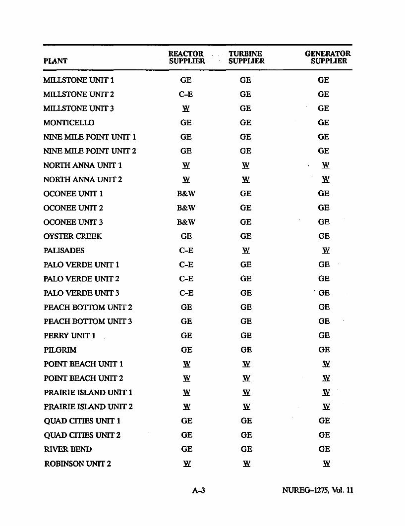
REACTOR TURBINE GENERATORPLANT SUPPLIER SUPPLIER SUPPLIER
MILLSTONE UNIT 1 GE GE GE
MILLSTONE UNIT 2 C-E GE GE
MILLSTONE UNIT 3 3y GE GE
MONTICELLO GE GE GE
NINE MILE POINT UNIT 1 GE GE GE
NINE MILE POINT UNIT 2 GE GE GE
NORTH ANNA UNIT 1 WW w
NORTH ANNA UNIT 2 W W W
OCONEE UNIT 1 B&W GE GE
OCONEE UNIT 2 B&W GE GE
OCONEE UNIT 3 B&W GE GE
OYSTER CREEK GE GE GE
PALISADES C-E 3y XW
PALO VERDE UNIT 1 C-E GE GE
PALO VERDE UNIT 2 C-E GE GE
PALO VERDE UNIT 3 C-E GE GE
PEACH BOTTOM UNIT 2 GE GE GE
PEACH BOTTOM UNIT 3 GE GE GE
PERRY UNIT 1 GE GE GE
PILGRIM GE GE GE
POINT BEACH UNIT 1 W W W
POINT BEACH UNIT 2 y W W
PRAIRIE ISLAND UNIT 1 y W W
PRAIRIE ISLAND UNIT 2 y W W
QUAD CITIES UNIT 1 GE GE GE
QUAD CITIES UNIT 2 GE GE GE
RIVER BEND GE GE GE
ROBINSON UNIT 2 XW W XW
A-3 NUREG-1275, Vol. 11
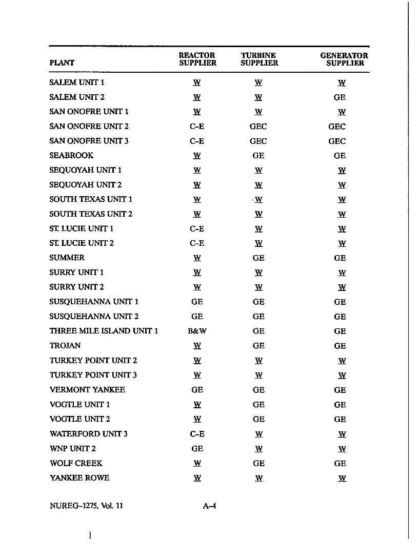
REACTOR TURBINE GENERATORPLANT SUPPLIER SUPPLIER SUPPLIER
SALEM UNIT 1 W W -w
SALEM UNIT 2 -w -w GE
SAN ONOFRE UNIT 1 W W -w
SAN ONOFRE UNIT 2 C-E GEC GEC
SAN ONOFRE UNIT 3 C-E GEC GEC
SEABROOK -w GE GE
SEQUOYAH UNIT 1 W -w W
SEQUOYAH UNIT 2 W W Xw
SOUTH TEXAS UNIT 1 W -W W
SOUTH TEXAS UNIT 2 W W W
ST LUCIE UNIT 1 C-E W W
ST LUCIE UNIT 2 C-E W W
SUMMER Xw GE GE
SURRY UNIT 1 W W Xw
SURRY UNIT 2 W W W
SUSQUEHANNA UNIT 1 GE GE GE
SUSQUEHANNA UNIT 2 GE GE GE
THREE MILE ISLAND UNIT 1 B&W GE GE
TROJAN W GE GE
TURKEY POINT UNIT 2 W W Xw
TURKEY POINT UNIT 3 W Xw W
VERMONT YANKEE GE GE GE
VOGTLE UNIT 1 W GE GE
VOGTLE UNIT 2 W GE GE
WATERFORD UNIT 3 C-E W Xw
WNP UNIT 2 GE W W
WOLF CREEK Xw GE GE
YANKEE ROWE W W Xw
NUREG-1275, Vol. 11 A-4

REACTOR TURBINE GENERATORPLANT SUPPLIER SUPPLIER SUPPLIER
ZION UNIT 1 WW 3with BB 3ylow pressureturbine stages
ZION UNIT 2 -W 3XVwith BB 3ylow pressure
turbine stages
A-S AMis-Chalmers/Siemens
BB Brown Boveri
B&W Babcock & Wilcox
C-E Combustion Engineering
GE General Electric
GEC English Electric
XW Westinghouse
A-5 NUREG-1275, Vol. 11


APPENDIX B
SUMMARY OF SERT REPORT RECOMMENDATIONS


SUMMARY OF SERT REPORT RECOMMENDATIONS*
1. Plant Design
a. Evaluate the turbine protectionsystems for design enhancements.
b. Complete detailed root-causeassessment of solenoid failures andimplement corrective actions toprevent recurrence.
c. Determine source of orifice foreignmaterial and implement appropri-ate corrective actions.
d. Evaluate the need for designchanges to the front standard toaddress identified human factorsdeficiencies, and initiate asrequired.
e. Finalize engineering analysis todetermine all origins of steam flowenergy which resulted in the turbineoverspeed event, and place finalreport of this analysis in the SERTfile for this event.
f. Evaluate the AST pressure switchsettings for adequacy for protectionas well as control functions.
2. Programs
a. Perform a matrix review of turbinemulti-trip and other secondaryplant components to assure ade-quate testing.
b. Establish and complete routinecalibration cycles for AST pressureswitches.
c. Review Administrative Controls forcommitment tracking and reviseapplicable administrative proce-
*Dire .quotations from Public Service Electric and Gas Com-in, S-.ificant Event RTe e 7Iam (SERT) Report No.
Gen 9126,alem Unit 2":cltorfthrbine 'lMip and "Thrbine/Generator Failure of November 9, 1991," December 20, 1991.
dure(s). Address identified short-comings associated with failure toimplement the 1990 LER commit-ment to change out the Unit 2solenoid valves (e.g., require docu-mentation of commitmentmodifications).
d. Implement independent full func-tional, hydraulic operationalperiodic testing of the four turbineprotection solenoid valves.
e. Review present priority of plans forRCM to address the Salem mainturbine and support systems inlight of this event, and makechanges as necessary.
f. Evaluate the need for a LicenseChange Request to clarify TechnicalSpecification 3/4.3.4 "TIrbineOverspeed Protection."
g. Review technical specification sur-veillance testing methodologies toensure no other instances of failureto test components independentlyexist, which could involve TechnicalSpecification violations or reduc-tions in protective functionsredundancy.
h. Review the process of Technicalspecification license changerequests to determine why LCO3/4.3.4 was not clarified when it waslast amended. Identify actions toprevent recurrence.
i. Re-evaluate the basis for 30 dayfront standard testing as specifiedby vendor; implement less frequenttesting if justifiable.
j. Work with Operations and Com-puter Engineering to implement aprogram to save an optimal set ofSPDS and P-250 data for future
B-1 NUREG-1275, Vol. 11

use during event evaluation, sep-arate from the AD-16 program.
k. Revise the turbine front standardtest procedure (OP 111-1.3.7), priorto the next test performance foreither Unit. Review for inclusionHuman Factors Report comments.
1. Incorporate discussion of operationof Steam Dumps, MS10s and EHCduring Unit THp Events into opera-tor training.
m. Re-emphasize to all Emergencycoordinators that EP proceduresand Attachments are not standalone documents.
n. Assess AOP-Fire-1 guidance con-cerning operation of equipmentinvolved in or contributing to a fire,and revise as needed.
o. Enhance training on de-escalatingevents and use of procedure EPIP405.
p. Revise ECG Attachments 1, 2and 3 with recommendedenhancements.
q. Revise AOP-Fire-1, FRS-1-001,EPIP 202 and EGG Attachment 8to better address offsite assistancerequests.
r. Revise the Initial Contact MessageForm Attachments 2 and 3 toenhance guidance in terminatingevents.
s. Provide refresher training on pageractivation to primary andsecondary communicators.
t. Communicate the inadequateprioritization of turbine failure to
trip industry events, and otherlessons learned, to the nuclearindustry via INPO.
u. Evaluate 10 CFR Part 21notification for solenoid valvefailures.
v. Continue implementation ofNuclear Department programsincluding:
- Reaching Our Vision
- Commitment Management
- Reliability CenteredMaintenance
- Salem Revitalization
- Work Standards Practices
3. Personnel
a. Plant Management is to assurebehaviors/actions during the10/20/91 startup are understoodand appropriate corrective actionstaken.
b. Reinforce and clarify StandingNight Order Book Policies with allSROs on shift.
c. Review the decision-makingassociated with the deferral of theUnit 1 LER commitment to replaceUnit 2 solenoid valves "during thenext outage of sufficient duration,"and take corrective actions asappropriate.
d. Develop and present a communi-cations program on this event,emphasizing lessons learned.
NUREG-1275, Vol. 11 B-.2

APPENDIX C
CUSTOMER ADVISORY LETTER 92-02,"OPERATION, MAINTENANCE, TESTING OF, AND SYSTEM
EHNANCEMENTS TO TURBINE OVERSPEEDPROTECTION SYSTEM"*
*Reprinted with permission of Westinghouse Electric Corporation.


DISCLAIMER OF WARRANTIESAND UMITATION OF LIABILITY
THERE ARE NO UNDERSTANDINGS, AGREEMENTS, REPRESENTATIONS, ORWARRANTIES, EXPRESS OR IMPLIED, INCLUDING WARRANTIES OFMERCHANTABILITY OR FITNESS FOR A PARTICULAR PURPOSE, OTHER THANTHOSE SPECIFICALLY SET OUT IN ANY EXISTING CONTRACT BETWEEN THEPARTIES REGARDING THIS EQUIPMENT. ANY SUCH CONTRACT STATES THEENTIRE OBLIGATION OF SELLER. THE CONTENTS OF THIS DOCUMENT SHALL NOTBECOME PART OF OR MODIFY ANY PRIOR OR EXISTING AGREEMENT,COMMITMENT, OR RELATIONSHIP.
The Information recommendations and descriptions In this document aer based onWestinghouse's experience and judgment with respect to this equipment's operationand maintenance. THIS INFORMATION SHOULD NOT BE CONSIDERED AS ALLINCLUSIVE OR COVERING ALL CONTINGENCIES. If further Information Is required,Westinghouse Electric Corporation should be consulted.
NO WARRANTIES, EXPRESS OR IMPLIED, INCLUDING WARRANTIES OF FITNESSFOR A PARTICULAR PURPOSE OR MERCHANTABILITY, OR WARRANTIES ARISINGFROM THE COURSE OF DEALING OR USAGE OF TRADE, ARE MADE REGARDINGTHE INFORMATION, RECOMMENDATIONS, OR DESCRIPTIONS CONTAINED HEREIN.In no event will Westinghouse be responsible to the user In contract, In tort (includingnegligence), strict liability or otherwise for any special, Indirect, Incidental, orconsequential damage or loss whatsoever, Including but not limited to damage to orloss of use of equipment, plant, or power system; cost or capital; loss of profits orrevenues; cost of replacement power, additional expenses In the use of existingpower facilities; or claims against the user by Its customers, resulting from use of theInformation, recommendations, or descriptions contained herein.
C-iii NUREG-1275, Vol. 11

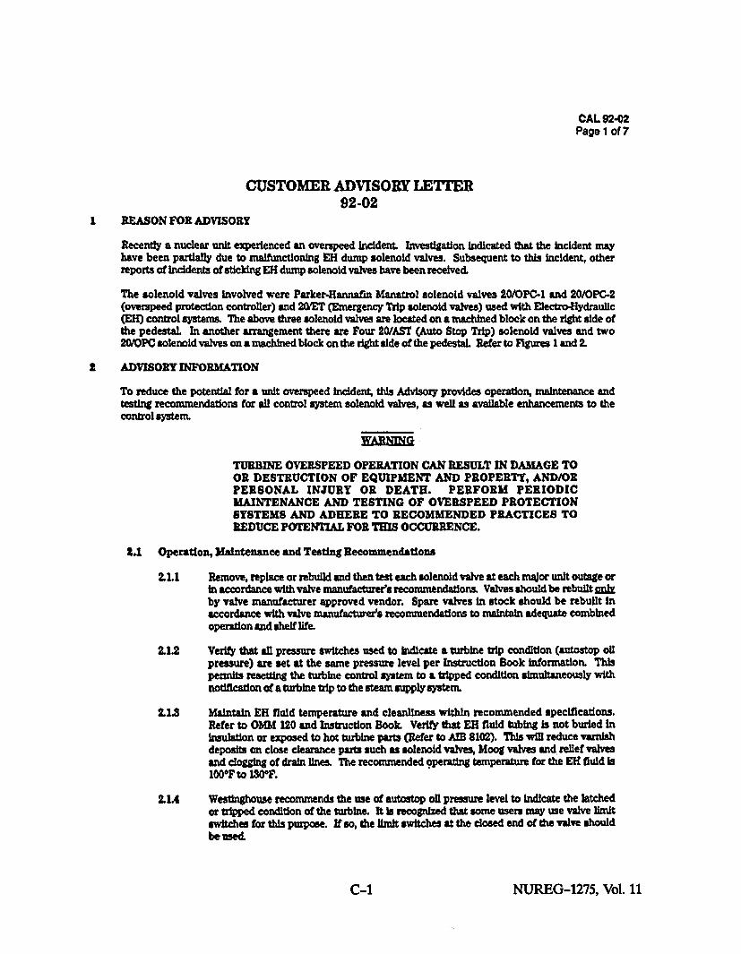
CAL 92-02Page 1 of 7
CUSTOMER ADVISORY LETFER92-02
REASON FOR ADVISORY
Recently a nuclear unit experienced an overspeed Incident. Investigation Indicated that the incident mayhave been partially due to malfunctioning EH dump solenoid valves. Subsequent to this incident, otherreports of Incidents of sticking EH dump solenoid valves have been received.
The solenoid valves Involved were Parker-Hannafin Manatrol solenoid valves 20/OPC-I and 20/OPC-2(overspeed protection controller) and 20/ET (Emergency Trip solenoid valves) used with Electro-Hydraullc(Eli) control systems. The above three solenoid valves are located on a machined block on the right side ofthe pedestal. In another arrangement there are Four 20/AST (Auto Stop Trip) solenoid valves and two20/PC solenoid valves on a machined block on the right side of the pedestal. Refer to Figures I and 2.
ADVISORY INFORMATION
To reduce the potential for a unit overspeed Incidenrt this Advisory provides operation, maintenance andtesting recommendations for all control system solenoid valves, as well as available enhancements to thecontrol system.
WARNIN
TURBINE OVERSPEED OPERATION CAN RESULT IN DAMAGE TOOR DESTRUCTION OF EQUIPMENT AND PROPERTY, AND/ORPERSONAL INJURY OR DEATH. PERFORM PERIODICMAINTENANCE AND TESTING OF OVERSPEED PROTECTIONSYSTEMS AND ADHERE TO RECOMMENDED PRACTICES TOREDUCE POTENTIAL FOR THIS OCCURRENCE.
2.1 Operation, Maintenance and Testing Recommendations
2.1.1 Remove, replace or rebuild and then test each solenoid valve at each major unit outage orIn accordance with valve manufacturer's recommendations. Valves should be rebuilt wnlyby valve manufacturer approved vendor. Spare valves in stock should be rebuilt Inaccordance with valve manufactutres recommendations to maintain adequate combinedoperation and shelf life.
2.1.2 Verify that all pressure switches used to indicate a turbine trip condition (antostop oilpressure) are set at the same pressure level per Instruction Book information. Thispermits resetting the turbine control system to a tripped condition simultaneously withnotification of a turbine trip to the steam supply system.
2.1.3 Maintain EH fluid temperature and cleanliness within recommended specifications.Refer to OMM 120 and Instruction Book. Verify that EH fluid tubing Is not buried InInsulation or exposed to hot turbine parts (Refer to AM 8102). This will reduce varnishdeposits on close clearance parts such as solenoid valves, Moog valves and relief valvesand clogg"n of drain lines. The recommended operating temperature for the ER fluid Is100F to 1W0E.
.1.4 Westinghouse recommends the use of autostop oil pressure level to Indicate the latchedor tripped condition of the turbine. It Is recognized that some users may use valve limitswitches for this purpose. If so, the limit switches at the closed end of the valve shouldbewed.
C-1 NUREG-1275, Vol. 11
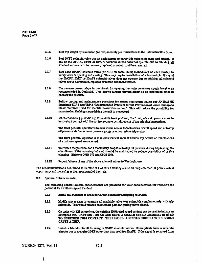
CAL 92-02Page 2 of 7
2.1.5 Test tip weight by simulation (oil test) monthly per instructions in the unit Instruction Book.
2.1.8 Test 2MiET solenoid valve tip on each startup to verify this valve is opening and closing Ifany of the 20/OPC, 20/ET or 20/AST solenoid valves does not operate due to sticklng, alsolenoid valves are to be removed, replaced or rebuilt and then retested.
2.1.7 Test each 20/OPC solenoid valve (or AGO on some units) Individually on each startup tover* valve Is opening and closing. This may require installation of a test switch. If any ofthe 20/OPC, 20YET or 20/AST solenoid valves does not operate due to sticking, all solenoidvalves are to be removed, replaced or rebuilt and then retested.
2.L8 Use reverse power relays in the circuit for opening the main generator circuit breaker asrecommended in OMM092. This allows turbine driving steam to be dissipated prior toopening the breaker.
2.1.9 Follow testing and maintenance practices for steam non-return valves per ANSIASMEStandards TDP-l and TDP-2 *Recommended Practices for the Prevention of Water Damage toSteam Turbines Used for Electric Power Generation.' This will reduce the possibility foruncontrolled flashing steam driving the unit to overspeed.
2.1.10 When conducting periodic trip tests at the front pedestal, the front pedestal operator must beIn constant contact with the control room to permit receipt of any tripping irwructions.
The f-ont pedestal operator is to have visual access to indications of unit speed and autostopoil pressure via tachometer pressure pauge or other turbine trip status.
The ftr pedestal operator Is to release the test valve If turbine trip occurs or if indicationsof a unit overspeed are received.
2.1.11 To reduce the potential for a momentary drop In autostop oil pressure during trip testing, thecleanliness of the autostop lube oil should be maintained to reduce possibility of orificeclog•gin (Refer to OMM 072 and OMM 106).
2.1.12 Report failures of any of the above solenoid valves to Westinghouse.
The recommendations contained In Section 2.1 of this Advisory are to be implemented at your earliestopportunity and thereafter at the recommended intervals.
2.2 System Enhancements
The following control system enhancements are provided for your consideration for reducing thepotential for a unit overspeed incidenL
2.1 Install coil monitors to check for circuit continuity of tripping solenoids.
2±= Modify trip system to energize all available valve test solenoids simultaneously with tripsolenoids. This would provide an alternate path for gettng valves closed.
2.L3 On units with ZH controllers, the existing 11096 rated speed contact can be used to Initiate anoverspeed tip. CAUTION - ON AN AEH UNIT, A SINGLE SPEED CHANNEL IS USEDTO ENERGIZE THIS CONTACT. THEREFORE, A SINGLE HIGH FAILURE COULDCAUSE A TRIP.
2.2.4 Install a latch-in circuit to energize 20/ET solenoid valves. Some plants have a separateelectric trip to energize 20/ET other than that used for 20/AST. If the signal Is removed from
NUREG-1275, Vol. 11 C-2

CAL 92-02Page 3 of 7
the 20/ET solenoid valve, the 20/ET will allow reestablishing the high pressure fluid. Ifthe parallel path which energizes the 20/AST did not function, the steam valves couldreopen creating a potential for overspeed. To maintain the unit In a tripped conditionfrom an external signal to the 200rT, a latch-in relay Is recommended.
2U5 On units with mechanical trip systems, one 20/AST Is standard. During trip testing at thefront pedestal, this solenoid Is made ineffective. A second 20/AST (style 387A995002) canbe installed on the HP oil supply side of the test handle to allow electrical trips to beeffective even when the test handle is held. Refer to Figure 3.
2,2.6 Install a pressure switch (style 889C416015) In the main (shaft) oil pump discharge todetect an overspeed condition. This feature would be most beneficial for customers whodesire an alternate electrical overspeed protection channel This pressure switch couldbe set at a level equivalent to 112% rated speed tonitiate a turbine trip. To avoid anInadvertent trip, a2 out of 3 scheme should be used.
2.2.7 On 1509 and 3009 systems, add a load drop anticipator system to immediately close thegovernor and interceptor valves on breaker opening. The valves would stay closed untilthe steam flow drops to a relatively low level
2.2.8 To reduce the possibility of tripping the unit during testing of the trips at the frontpedestal, Install a pressure gauge on the trip block side (mechanical trip system) of thetest handle. See Flgures 3 and 4. The operator should verify that autostop pressure hasbeen re-establlshed before releasing the test handle..
The recommendations contained In Section 2.2 can be Implemented at the next opportunity to complete thescope.
The recommendations contained in sections 2.2.1, 2.2.2, 2.2.6 and 2.2.8 apply to all units. Therecommendations In 2.2.3 and 2.2.4 apply to Eli systems. The recommendation contained in 2.2.6 applies to300# EH systems with M3-1 trip supplied prior to 1962.
If additional Information relative to or clarification of these recommendations is required, contact yourlocal Technical Service Manager or Generation Specialist
C-3 NUREG-1275, Vol. 11

CAL 92-02Page 4 of 7
EMERGENCY AND OVERSPEEDPROTECTION CONTROLLER
SYSTEM(EXISTING)
[•83
TURBINE ASTTRIPBLOCK INTEFACEI
SUPPP
LUBE OIL
SYSTEM) ICovERsPE. -
PROTECTION ICCNTRCLLER---------- s20-2.. . ..-. OPC F
LOGIC O PC
FIGURE 1
VALVE
"EADER
NUREG-1275, Vol. 11 C-4
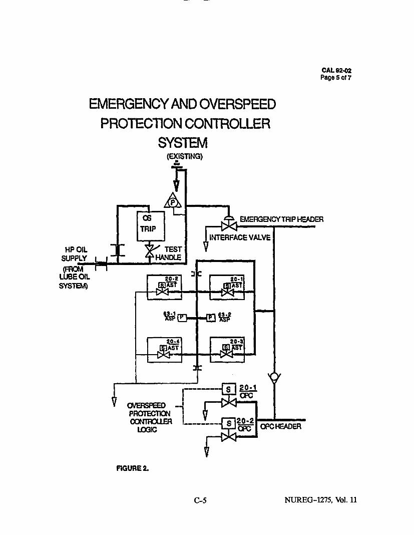
CAL 92-02Page 5 of 7
EMERGENCY AND OVERSPEED
PROTECTION CONTROLLERSYSTEM
(EXISTING)
P
06 EMERGENCY TRIP HEADERTRIP
HP OLINTERFACE VALVE
suPPLY -HANDLE(FROM r-
LUBEOIL 20.2 3[ 2-i
F200,ASTI
-
VSPROTECTION1CONROER'2- p
LOGIC ccOOHAE
FIGURE 2.
C-5 NUREG-1275, Vol. 11
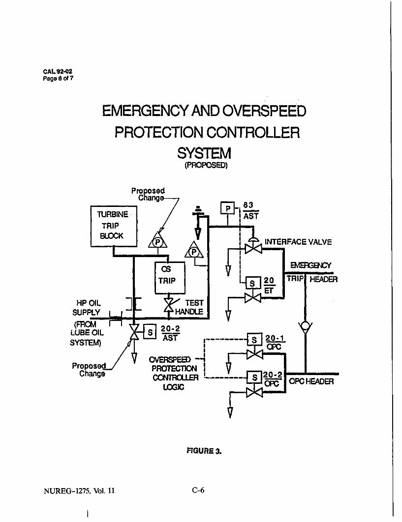
CAL 92-02Page 6 of 7
EMERGENCY AND OVERSPEEDPROTECTION CONTROLLER
SYSTEM(PROPOSED)
INTERFACE VALVE
FIGURE 3.
NUREG-1275, Vol. 11 C-6
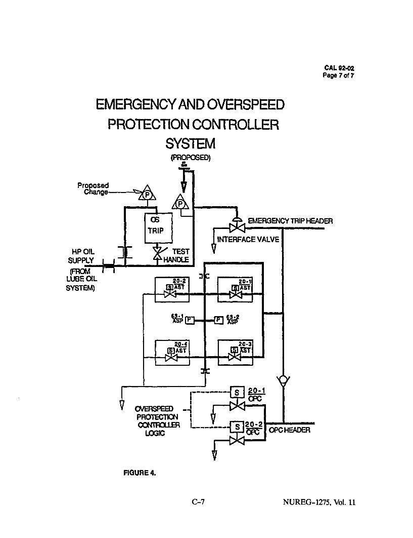
Pro~
HP OILSUPPLY
CAL 92.02Page 7 of 7
EMERGENCY AND OVERSPEEDPROTECTION CONTROLLER
SYSTEM(PROPOSED)
osednge
P
Os EMERGENCY TRIP HEADERTRIP
INTERFACE VALVE
TEST r-r- _-HANDLE __
L 20-2201
2 A- 2-3
PROTECTION I
LOGIC 4.
FIGURE 4.
SYSTEM)
C-7 NUREG-1275, Vol. 11

APPENDIX D
AVAILABILITY IMPROVEMENT BULLETIN 9301,"SYSTEM TURBINE OVERSPEED PROTECTION SYSTEM"*
*Reprinted with permission of Westinghouse Electric Corporation.


DISCLAIMER OF WARRANTIESAND LIMITATION OF LIABILITY
THERE ARE NO UNDERSTANDINGS, AGREEMENTS, REPRESENTATIONS, ORWARRANTIES, EXPRESS OR IMPLIED, INCLUDING WARRANTIES OFMERCHANTABILITY OR FITNESS FOR A PARTICULAR PURPOSE, OTHER THANTHOSE SPECIFICALLY SET OUT IN ANY EXISTING CONTRACT BETWEEN THEPARTIES REGARDING THIS EQUIPMENT. ANY SUCH CONTRACT STATES THEENTIRE OBLIGATION OF SELLER. THE CONTENTS OF THIS DOCUMENT SHALL NOTBECOME PART OF OR MODIFY ANY PRIOR OR EXISTING AGREEMENT,COMMITMENT, OR RELATIONSHIP.
The Information recommendations and descriptions In this document are based onWestinghouse's experience and judgment with respect to this equipment's operationand maintenance. THIS INFORMATION SHOULD NOT BE CONSIDERED AS ALLINCLUSIVE OR COVERING ALL CONTINGENCIES. If further Information Is required,Westinghouse Electric Corporation should be consulted.
NO WARRANTIES, EXPRESS OR IMPLIED, INCLUDING WARRANTIES OF FITNESSFOR A PARTICULAR PURPOSE OR MERCHANTABILITY, OR WARRANTIES ARISINGFROM THE COURSE OF DEAUNG OR USAGE OF TRADE, ARE MADE REGARDINGTHE INFORMATION, RECOMMENDATIONS, OR DESCRIPTIONS CONTAINED HEREIN.In no event will Westinghouse be responsible to the user In contract, In tort (includingnegligence), strict liability or otherwise for any special, Indirect, Incidental, orconsequential damage or loss whatsoever, Including but not limited to damage to orloss of use of equipment, plant, or power system; cost or capital; loss of profits orrevenues; cost of replacement power; additional expenses In the use of existingpower facilities; or claims against the user by Its customers, resulting from use of theInformation, recommendations, or descriptions contained herein.
D-iii NUREG-1275, Vol. 11

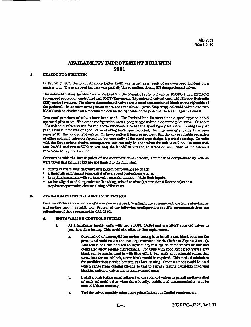
AAB 9301Page 1 of 16
AVAILABILITY IMPROVEMENT BULLETIN9301
I. REASON FOR BULLETIN
In February 1I92, Customer Advisory Letter 92-02 was issued as a result of an overspeed incident on anuclear unit. The overspeed Incident was partially due to malfumctioning EH dump solenoid valves.
The solenoid valves involved were Parker-Hannifin Manatrol solenoid valves 20/OPC-l and 20/OPG-2(overspeed protection controller) and 20/ET (Emergency Trip solenoid valves) used with Electro-Hydraullc(EH) control systems. The above three solenoid valves are located on a machined block on the right side ofthe pedestal. In another arrangement there are four 20/AST (Auto Stop Trip) solenoid valves and two20/OPC solenoid valves on a machined block on the right side of the pedestal. Refer to FIgures 1 and 2.
Two configurations of valvi. have been used. The Parker-Hannifin valves use a spool type solenoidoperated pilot valve. The other configuration uses a poppet type solenoid operated pilot valve. Of about1000 solenoid valves in use for the above functions, 40% use the spool type pilot valve. During the pastyear, several Incidents of spool valve sticking have been reported. No incidents of sticking have beenreported for the poppet type valves. On Investigation It became apparent that the key to reliable operationof either solenoid valve configuration, but especially of the spool type design, is periodic testing. On unitswith the three solenoid valve arrangement, this can only be done when the unit Is off-line. On units withfour 20/AST and two 20/OPC valves, only the 20/AST valves can be tested on-line. None of the solenoidvalves can be replaced on-line.
Concurrent with the investigation of the aforementioned Incident; a number of complementary actionswere taken that included but are not limited to the following:
" Survey of users soliciting valve and system performance feedback" A thorough engineering reappraisal of overspeed protection systems." In depth discussions with variousvalve manufacturers to obtain their inputs." An Investigation of dump valve orifice sizig related to slow (greater than 0.5 seconds) reheat
stopAnterceptor valve closure during offline tests.
2. AVAILBILITY IMPROVEMENT INFORMATION
Because of the serious nature of excessive overspeed, Westinghouse recommends system redundanciesand on-line testing capabilities. Several of the following configuration specific recommendations arereiterations of those contained in CAL 92M-2M
A. UNITS WITH EH CONTROL SYSTEMS
1. As a minimum, modify units with two 20/OPC (AGG) and one 20/ET solenoid valves topermit on-line testn This could also allow on-line replacement.
a. One method of accomplishing on-line testing Is to Install a test block between thepresent solenoid valves and the large machined block. (Refer to FIgures 3 and 4).This test block can be used to individually test the solenoid valves on-line andcould also allow on-line maintenance. For units with spool type pilot valves, thisblock can be sandwiched In with little effort. For units with solenoid valves thatscrew into the main block, a new block would be required. This method minimizesthe modifications needed but requires local testing. Other methods could be usedwhich range from coming off-ine to test to remote testing capability involvingblocking solenoid valves and pressure transducers.
b. Install a push button panel adjacent to the solenoid valves to permit on-line testingof each solenoid valve when done locally. Additional instrumentation will beneeded if done remotely.
C. Test the valves monthly using appropriate Instruction Leaflet requirements.
D-1 NUREG-1275, Vol. 11

AIB 9301Page 2 ef 16
2. As a minimum, modify units with an electrical trip system and having two 20/OPC and four20/AST solenoid valves to allow for on-line testing of 20OlPC valves. This could also allowon-line replacement of valves.
a. One method of accomplishing on-line testing Is to install a test block between thepresent 20/OPC solenoid valves and the large machined block. (Refer to Figures 3and 4 ). This test block can be used to individually test the solenoid valves on-lineand could also allow on-line maintenance. For units with spool type pilot valves,this block can be sandwiched in with little effort. For units with solenoid valvesthat screw Into the main block, a new block would be required. This methodminimizes the modifications needed but requires local testing. Other methodscould be used which range from coming off-line to test to remote testing capabilityinvolving blocking solenoid valves and pressure transducers. Test the valvesmonthly using appropriate Instruction Leaflet requirements.
b. Install a push button panel adjacent to the solenoid valves to permit testing eachsolenoid valve when done locally. Additional Listrumentation will be needed ifdone remotely.
c. The four 20/AS? solenoid valves can presently be tested in pairs, not Individually.Install a push button panel adjacent to the solenoid valves to allow individualtesting of these valves. It is suggested that a test block be installed for eachsolenoid valve to allow on-line maintenance of these valves. Test the valvesmonthly using appropriate Instruction Leaflet requirements.
3. Remove, replace or rebuild and then test each OPC, ET and AST solenoid valve in the EHlines at each major unit outage in accordance with valve manufacturer's recommendations.Spare valves in stock for five years or more should be rebuilt prior to being placed Inoperation. Valves should be rebuilt only by valve manufacturer approved vendor.
4. Verify that all pressure switches used to indicate a turbine trip condition (autostop oilpressure) are set at the same pressure level per Instruction Book Information. Thispermits resetting the turbine control system to a tripped condition simultaneously withnotification of a turbine trip to the steam supply system.
5& Maintain EH fluid temperature and cleanliness within recommended specifications. (Referto OMM 120 and Instruction Book). Verf that Eli fluid tubing is not buried in insulationor exposed to hot turbine parts (Refer to AIB 8102). This will reduce varnish deposits onclose clearance parts such as solenoid valves, Moog valves and relief valves and cloggingof drain lines. The recommended operating temperature for the EH fluid Is 100*F to 130"F.Refer to IL. 1250-4290 Care, Handling & Application of Control System Fluid' forappropriate safety precautions.
61 Install a latch-in (seal-in) circuit to energize 2MYEr solenoid valves. (Refer to Figure 5).Some plants have a separate electric trip to energize 2M other than that used for 20/AST.If the signal is removed from the 20/ET solenoid valve, the 20/ET will allow re-establishilngthe high pressure fluid. If the parallel path which energizes the 20/AST did not flmctlon,the steam valves could reopen creating a potential for overspeed. A latch-in circuit willmaintain the unit in a tripped condition when the 20/ET solenoid receives an externalsignal.
7. Test each 20/OPC (or AGG) and each 20/AS? or 2M solenoid valve individually on eachstartup. If any valve does not operate due to sticking, all solenoid valves should beremoved, replaced or rebuilt and then retested.
8. For all valve actuators equipped with a three inch dump valve, Inspect the orifice whichlimits the flow of fluid from the high pressure header to the emergency trip header to verifythat the diameter is 0.031 inches or less. Other valve actuators, equipped with the 7/8 Inchdump valve, do not requre this Inspection as they do not have this orifice. Figure 6 shows
NUREG-1275, Vol. 11 D-2

AIB 9301Page 8 of 16
a fluid diagram for actuators equipped with both tes of dump valves. Figures 7 and 8show an exploded outline of typical valve actuators equipped with the 7/8 and 3 Inch dumpvalves (respectvely).
The orifice to be inspected (on valve actuators equipped with the three Inch dump valve) islocated most commonly In the orifice plate that Is sandwiched between the machinedblock and the test solenoid valve, as shown in Figure & If the orifice diameter is greaterthan 0.031 Inches, It is recommended that It be replaced with another having the 0.031 Inchdiameter. Some valve actuators equipped with the three Inch dmp valve do not hve anorifice plate and instead the orifice was drilled Into the machined block underneath thetest solenoid valve; for this configuration, If the orifice diameter Is greater than 0.031Inches, it Is recommended that an orifice plate be added having an orifice diameter of 0.031Inches, as shown in Figures (the drilled orifice In the machined block should be left as Is).
9. Inspect and verify that the vented drain line(s), which return fluid to the ER Reservoirfrom the emergency trip header interface diaphragm valve and emergency trip controlblock connections (located at the governor pedestal), are of the proper size, 1.00 Inch ODby 0.120 Inch wall thickness tubing.
Also verify that the vented drain line(s) are located and adequately protected against apossible mishap which could cause a reduction In the flow capacity of these line(sl Itshould be noted that current Westinghouse practice calls for two Independent, fullcapacity vented drain lines to be run to the ER Reservoir In parallel In order to helpminhmize this risk. Additionally, a cross-te between the two vented drain lines near theirconnections to the interface diaphragm valve and emergency trip control block is alsorecommended.
10. Poppet type solenoid valves will be furnished when replacementfspare solenoid valves areordered. They are a direct replacement for the spool type valves with regards to form, fitand functlon and will mount directly in place of spool type valves. (Refer to Figure 4).Westinghouse Style #822A84S001 is replaced by 807J9400
B. UNITS WITH MECHANICAL TRIP SYSTEMS
L On units with mechanical trip systems, one 20/1AST Is standard. During trip testing at thefront pedestal, this solenoid is made Ineffective. A second 20A1SF should be installed onthe HP oil supply side of the test handle to allow electrical trips to be effective even whenthe test handle is held. (Refer to Figure 9).
2. In addition to testing the low bearing oil, low vacumu end hig thrust trips, devies an amonthly basis, the trip solenoid 20/AST In the mechanical trip device assembly should betested monthly using appropriate Instruction Leaflet requirements. Caution should beexercised when making this test to assure that other plant tripping circuits are notInvolved.
2 At each major outage, visually Inspect and manually manipulate the trip assemblymechanism to detect any worn parts, loose pins, ruptured bellows or sticking mechanismRepair as needed.
C. UNITS WITH MECHANICAL HYDRAUUIC CONTROL SYSTEMS
It Is recommended that these units have as a minimunm
L An auxiliary governor which will take action to arrest turbine speed to a value below thetrip set point This function may be called a preemergency governor.
D-3 NUREG-1275, Vol. 11
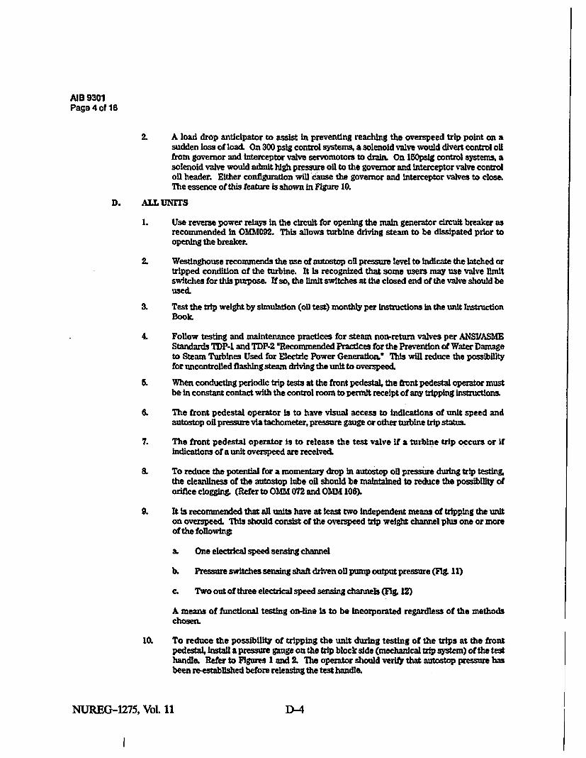
AIB 9301Page 4 of 16
2. A load drop anticipator to assist in preventing reaching the overspeed trip point on asudden loss of load. On 300 pslg control systems, a solenoid valve would divert control oilfrom governor and Interceptor valve servomotors to drain. On 150psig control systems, asolenoid valve would admit high pressure oil to the governor and interceptor valve controloil header. Either configuration will cause the governor and interceptor valves to close.The essence of this feature is shown in Figure 10.
D. ALL UNITS
1. Use reverse power relays in the circuit for opening the main generator circuit breaker asrecommended In OMM092. This allows turbine driving steam to be dissipated prior toopening the breaker.
2. Westinghouse recommends the use of autostop oil pressure level to indicate the latched ortripped condition of the turbine. It Is recognized that some users may use valve limitswitches for this purpose. If so, the limit switches at the closed end of the valve should beused.
3. Test the trip weight by simulation (oil test) monthly per Instructions In the unit InstructionBook.
4. Follow testing and maintenance practices for steam non-return valves per ANSIIASMEStandards TDP. and TDP-2 "Recommended Practices for the Prevention of Water Damageto Steam Turbines Used for Electric Power Generation." This will reduce the possibilityfor uncontrolled flashing steam driving the unit to overspeed.
5. When conducting periodic trip tests at the front pedestal, the front pedestal operator mustbe in constant contact with the control room to permit receipt of any tripping instructions.
6. The front pedestal operator Is to have visual access to indications of unit speed andautostop oil pressure via tachometer, pressure gauge or other turbine trip status.
7. The front pedestal operator is to release the test valve If a turbine trip occurs or Ifindications of a unit overspeed are received.
8. To reduce the potential for a momentary drop in autostop oil pressure during trip testing.the cleanliness of the autostop lube oil should be maintained to reduce the possibility oforifice clogging. (Refer to OMM 072 and OMM 106).
9. It is recommended that all units have at least two independent means of tripping the uniton overspeed. This should consist of the overspeed trip weight channel plus one or moreof the folowing
a. One electrical speed sensing channel
b. Pressure switches sensing shaft driven oil pump output pressure (FIg. 11)
C. Two out of three electrical speed sensing channels (FIg. 12)
A means of functional testing on-line is to be Incorporated regardless of the methodschosen,
10. To reduce the possibility of tripping the unit during testing of the trips at the frontpedestal, Install a pressure gauge on the trip block side (mechanical trip system) of the testhandle. Refer to Figures I and2. The operator should verify that autostop pressure hasbeen rmestablished before releasing the test handle.
NUREG-1275, Vol. 11 D-4

AIB 9301Page sof 15
EMERGENCY AND OVERSPEEDPROTECTION CONTROLLER
SYSTEM
63AST
INTERFACE VALVE
HEADER
HP OILSUPPLY
SYST94
PONROTECTOLWGI
OPO HEAflER
FIGURE 1
D-5 NUREG-1275, Vol. 11
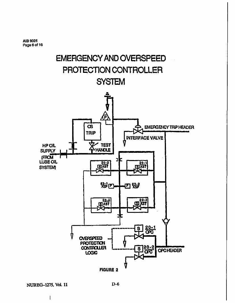
AIB 9301Page 6 of 16
EMERGENCY AND OVERSPEEDPROTECTION CONTROLLER
SYSTEM
TRIPINTERFACE VALVE
HP OIL TSTSUPLY" ' HCILE __
LUBE OIL 2o.aSYSTEM Asl AS
MSA
FIGURE 2
TRIP HEADER
H-EADER
NUREG-1275, Vol. 11 D-6

AIB 9301Page 7 of 16
SOLENOID VALVE ADAPTER
SPRING RETURNI LOCALmmIAL VALVE TESTSUTTON EXISTING
ORIFICE CIRCUIT
20101'C ORE?
OI'C OR ETS OVALVE
LiDRAIN
L This arrangement does not apply to:
L Manifold blocks with cartridge valves mounted directly in the block. For theseunits, a new manifold block and solenoid valves are required.
b. The solenoid valves designated 20/AST on manifold blocks with 6 valves.Presently, 20-1/AST thorough 20-4/AST valves can be tested online but notreplaced online. New solenoid valves and an alteration to the manifold wouldbe required in order to permit on line replacement.
EL For remote testing, a variation of the above arrangement could be made by.
a. Replacing the manual valve with a normally open solenoid valve.
b. Adding a pressure transmitter and receiver to read the gauge pressure.
c. Adding a solenoid valve test panel in the control room.
FIGURE 3
D-7 NUREG-1275, Vol. 11

AIB 9301Page 8 of 16
SOLENOID VALVE ADAPTER
PARKER-HANNIFINSOLENOID VALVE
REMOVE EXISTING PLUGREPLACE WITH ROOT VALVE
AND GAUGE
SOLENOID BLOCK
L OR
SPRING RETURNNORMALLY OPEN
BALL VALVE
DRAINHIGH PRESSURE-
EXISTINO MANIFOLD BLOCK
FIGURE 4
NUREG-1275, Vol. 11 D-8

AIB 9301Page 9 of 16
LATCH IN OF 20/ET
63/AST
63/AST - CLOSES ON LOSS OF AUTIOSTOP OIL PRESSURE
20/ET - OPENS TO DUMP HIGH PRESSURE DKERGENCY TRIP LINE
The original intent of the 63/AST-20/ET circuit was to provide a redundant path to thediaphragm valve. Practice has indicated that many utilities energize 20/ET directly as aredundant path to 20/AST. As presently configured, ther is no'latch in circuit to keep 20/ETenergized. The circuit above is recommended to keep 20= energized until an operorpurposely resets the circuit.
FIGURE 8
D-9 NUREG-1275, Vol. 11

A18 9301Page 10 of 11
VALVE ACTUATOR WITH 7IV DUMP VALVE(not affected; for refe'ence only)
tRIP PtLOTVALVE
MR[EAT STOPVAL V
NPFLUSUPPLY
ORm
VALVE ACTUATOR WITH 30 DUMP VALVE
HP PLUSSUP,'.
FIGURE 8
NUTREG-1275, Vol. 11 D1D-10

AI 9301Page 11 of 16,
VALVE ACTUATOR WITH 7/8" DUMP VALVE(not affected; for reference only)
MACHIP4COBLOCK
LVDT.
SHUTOFF,VALVa T199MANDLE CYLINI•R
FIGURE 7
D-11 D-11NUREc-1275, Vol. 11
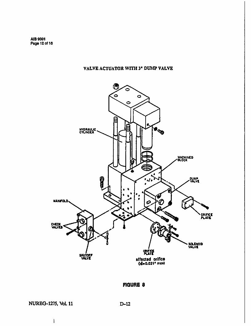
MIB 9301Page 12 of 16
VALVE ACTUATOR WITH 30 DUMP VALVE
ORIFMICPLATIC
CHECKX
SLVEOIDVAILV6
affected orifice(d=0.03V m64
FIGURE 8
NUREG-1275, VoL 11 D-12

AIB 9301Page 13 of 16
MECHANICAL TRIP SYSTEM
TRIP ITUBIN VALVE CLOSURE SYSTE•
HP OIL
20-2AST
Pi
FIGURE 9
D-13 NUREG-1275, Vol. 11

AIB 9301Page 14 of 16
LOAD DROP ANTICIPATOR
5
CONTROL OILSOLENIOIDVALVE
Installaionz
1. Install a pressure switch to use as a measure of steam flow. A convenient location is in thecrossover pipe. Calibrate the pressure switch to close at a pressure equivalent to 30% orgreater of rated flow.
2. Install a solenoid valve in the control fluid line.
QOration
1. Unit operating above 30% load with drop anticipator (WDA) pressure switch closed and themain breaker contact open.
2. Main breaker opens closing contract B. LDA contact remains closed.
3. Relay RI picks up and energizes control oil solenoid valve. This in turn closes governorand interceptor valves.
4. Steam flow reduces and WDA pressure switch opens.
5. Control oil pressure restored and normal governing function controls speed.
FIGURE 10
NUREG-1275, Vol. 11 D-14

AB 9301Page 15 of 16
OIL FRESSURE SWITCH ARXANGEKENT
- E-Y-
BLOCK &BLEED
lal 2al. la
2& 1i 3&1 3aITTTRIPSOLENOID
I
lb 2b_ ,t4L 3 b
DIDI
SUMAF DRIVEN OILPUMP OUTLET
One relatively easy way to add a backup overspeed protection circuit is to take advantage of theshaft driven oil pump pressure variation with shaft speed. Using 2 out of 3 logic reduces thechance of tripping due to a single switch failure.
Due to variations from unit to unit, the output pressure needs to be checked for each unit at theoverspeed trip level.
A normally closed contact from each pressure switch can be set to open above 95% speed andused to indicate a switch failure in the closed direction.
The pressure switches can be isolated and removed for calibration checking while online.Calibration should be done a minimum of once a year using a dead weight tester.
FIGURE 11
D-15 DNIEG-1275, Vol. 11
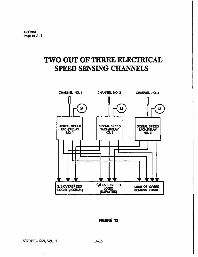
AIB 9301Page 18 of 18
TWO OUT OF THREE ELECTRICALSPEED SENSING CHANNELS
CHANNEL NO. 1 CHANNEL NO. 2 CHANNEL NO.3
FIGURE 12
NUREG-1275, Vol. 11 D-16

APPENDIX E
HAMMER VALVE


HAMMER VALVE
As noted in Section 4.3., the author of thisstudy examined an SOV which is used inEuropean fossil-unit TOPS systems. The valveundergoes long periods of inactivity but mustfunction properly when called upon to dumpEHC system hydraulic fluid. The enclosedtechnical articles; "Herion Directional ControlValve Type 5203468 for Hydraulic SafetyControl Systems Inoperative for Long PeriodsUnder Pressure," by A. Hoeger, and "'-ip
Control for Compact Drives for TurbineValves," by E. Kloster, explain in detail howthe valve works. In response to the author'sinquiries about the hammer valve's reliability,the enclosed June 10, 1993, letter fromN. Schauki of Siemens Nuclear PowerServices, Inc., notes that the hammer valve hasfunctioned on demand with 100-percentsuccess. However, some minor flange leakageshad been recorded.
E--1 NUREG-1275, Vol. 11

HERION directional control valve type 5203468for hydraulic safety control systems inoperativefor long periods under pressure* • •off Hoeger
Spool or scat-typO direcdonal controlvavejsbjcctdtohrulepsuefor l dengthy eidycdntu•f ros m
piston sticking. This means thax it isno longer possible to change the state
of the valve, because the s'witchngforces are not sufficient to free theJammed piston. This Is particularlycritica If switching Is performed bya•
spring o hydraulic pressure, as theseare agents which exert a static force onthe piston. Tests and case historieshave shown that a blow with a ham-met on the casing o a valve with ajammed piston Is enough to free thepiston, a feat which static force alonecould not accomplish.
In Safety Control sstems, the Safetyd onal control valve must beswitched by the return spring Ifpowerfalls. [ere must be no question of thepistonjamming.
The HERION type 5203468 valve wasdeveloped for reliable switching evenwhen the piston Isjammeddaftera longperiod of Inoperatlon.
A device designed to jerk the stickingpiston free Is mounted on the elcc-tromagnetically actuated spool valvewith return spring.
This device consists of a magnetic coil,a solenoid armature and a compres-sion spring. The armature Is of a de-sg which recIrculates the oIl whenthe valve Is switched.
If the impact solenoid (a) Isenergized,the piston moves aginst the force ofthe return spring to position (a).When the solenoid ) i de.ner-Szd, the return g pushes thepston bak to position ¶b). That Is themethod Fe operation hen the pistondoes not stc In the "soenoid (a)entersgize position.
Solenoid (a) and solenoid (b) am botheaergized at the same tinme. nhe arms-tam of solenoid (b) pretensions thespring tn solenoid (b). When solenoid(a) Is do-energized, solenoid (b) Isalso de-energized. In this way, the ar-mature is pushed toward position (a)by the spring In solenoid (b). As Itmoves, the armature travels throughthe space A and strukes the controlpiston If it ha stuck.
This "hammer action" frees the con-trol piston., the return spring can move
the piston to position (b). The sole
function of the armature in solenod(b) Is tolschar the brakaway im-
TA PU
HEFlON valve eaype 5203468
*Reprinted with permission of Herion-Werke KG.
NUREG-1275, Vol. 11 E--2
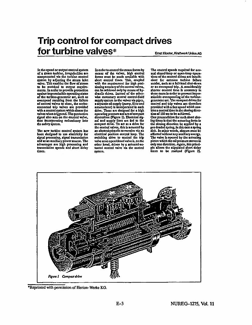
Trip control for compact drivesfor turbine valves* Ernst Kloster. Kraftwerc U~nion AG
in the speed or output controlsystcmof a steam turbine, I•rregularities arecompensated via the turbine controlsys=cm by adjusting the steam inletvalve. This enables the flow of steamto be matched to output require-merts. In order to provide protectionagainst Impermissible operating statesof the turbine-gencrator set, such asoverspeed resulting from the failureof control valves to dose, the series-connected trip valves are providedwith a control system which closes thevalves when triggered. The protectivesignal also acts on the control valve,thus incorporating redundancy intothe safety system.
The new turbine control system hasbeen designed to use electricity forsignal procesing, signal transmlssionand as an auxiliary power source. Theadvantages are high processing andtransmission speeds and short delaytimes.
In order to control the steam forces bymeans of the valves, high controlforces must be made available withshort control times. This, coupledwith the requirement for high posi-tioning accuracy of the control valves.can be achieved only by means of hy-draulic drives. Instead of the other-wise customary central control-fluidsupply system to the valves via pipes,a separate oil supply (pump. flterandaccumulator) Is incorporated in eachdrive. These are designed for a highoperating pressure and are of compactdimensions (Figure 1). Electrical sig-nal and supply lines are fed to thecompact drive. To act as a drive forthe control valves, this is actuated byan electrohydraulic servovalvc via anelectrical position control loop. Theswitching drive to control the tripvalve as an open/losed valve is. on theother hand, driven by a solenoid-ac-tuated control valve via the controlsyslem.
The control speeds required for nor-mal closed4oop or open4oop opera-tions of the control drives are insufl'ident for extrcme turbine failuremodes, such as a full-load shut-downor an overspeed trip. A considerablyshorter control time is necessary Inthese -ce in order to prevent Imper-missible overspeeding of the turbine-generator set. The compact drives forcontrol and trip vatvcs are thereforeprovided with a fast speed which ens-bles•a control time In the dosing direc-tion of ISO ms to be addceved.One precondition for such short dos-ing times is that the actuating forb inthe dosing direction be applied by apre-loaded spring, in this case aspringdisk. In other words, closure must beeffected without any auidliary energy.The valve Is opened by the actuatingpiston which the oil pressure moves inonly one direction. Again, this princi-ple allows the stipulated short delaytimes to be realized (Figure 2).
*Reprinted with permission of Herion-Werke KO.
E--3 NUREG-1275, Vol. 11
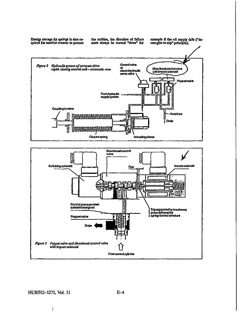
Enae tor by sings is also to-quhred for another reason: to protect
the turbine, the direction of failuremust always be toward -dose for
eape it the oil scTPIy falls ("de.tagi to We pfincapl).
Comolpressourwhen
Poppetvalve
Fiure3 Poppet ve vand diretiaocnrol valvewith bnpadtsolenoid
Tep~~birrakaayPfte by
ftOwnontrsudcYlndr
NUREG-1275, Vol. 11 E-4

To initiate the trip procedure, prps-sure beneath the piston must be se-duced and the volume of oil driven byspring tomce Into the oil reservoir. ThisIs attained by the rapid opening of anintegrated control system (Figure 3).When these valves open foratrip, theyconnect the cylinder with the reservoirparallel to the electrohydraulic servo-valve (control drive) or electro-magnetic control valve (openldoseddrive).As shown above, a failure, which Is tosay, the non-closure ofa control valve,leads to overspeed. Redundancy istherefore required, i.e. trip andcontrol valves are connected in pairs inseries in a valve combination. Furtherredundancy is achieved by the parallelconnection of two Integrated controlsystems (Figure 2).
Each of these is able to handle thedosing operation by virtue of the factthat, with over-dimensioned valvesand large duct cross-sections, theseries-connected orifice is dimen-sioned for the short closing time.The hydraulic fluid reaches each pop-pet valve separately via a directionalcontrol valve actuated electrically bythe control system (Figure 2). Thepoppet valves arc standard-Installa-don elements with piston guide.known as two-way poppet valves orcartridge valves. With the control oropen/dosed drive open and cylinderpressure applied beneath the valvecone, they are held dosed by the con-trol pressure which the solenoid valvebuilds up above the cone. The so[-enoids are energized in operation, do-energized for a trip, the control pres-sure is dissipated, the poppet valvesare opened by cylinder pressure. Thede-energize to dose principle appliesto the solenoid valvcs aIs well, in otherwords, if the electrical supply falls theturbine valves dose.The solenoid valves selected are ofslide design, in order to ensure that nosealing problems are encounteredduring Long periods in service. Slidevalves are subjected to frictionalforces and also adhesive forces If theyremain for considerable pesiods Inone position. The HERION solenoidvalves have been developed to cnsurethat they can be tripped reliably byspring force, even after a longstandstill period. To increase the re-liability of the dosing action evenwhen unexpected adhesive forces are
present, a second solenoid valve is fit-ted to the opposite side; when trippedby spring force, the armature of thissolenoid strikes against the controlslide (wimpact solenoid"). Ths Impactproduces an additional breakawaypulse (Figure3).Even with high ambient temperaturesand wide voltage tolerances, direc-tional control valves with impact sol-enoids 1"hammer valves") haveadequately large reserves of actuatingforce in the closing direction, shortdosing times with small tolerancesand low leakage-oil rates. This Is at-tained by precise balancing of thedose-tolerance springs with the sol-enoids and simdlarly dose tolerancesin clearance.
Like all the parts In the control s"stemof the compact drive, the solenoid val-ves are also subject to particularlyhigh cleanliness requirements.
The trip procedure is executed at in-tervals of approx. 14 days in thecourse of the testing of the turbineprotection system by an automatictest system.
Figure 4shows graphs fora trip proce-dure, measured with an experimentaldrive. These show trip signals, controlpressure downstream of the Impactsolenoid, control fluid pressure, thepressure belowthe control piston, andthe control piston travel as a functionof time.
I
Figur 4 Gnaphs of aqu ick dasur
E-5 NUREG-1275, Vol. 11

SIEMENS
June 10, 1993
National Regulatory CommissionMail Stop 9715Washington, DC 20555
Attention: Dr. Ornstein
Dear Dr. Ornstein:
Subject: Experience with "Hammer Solenoids Valvesw from Herion
According to the information we received from Mr. Gebauer at Siemens - KWU in MGIhelm,there were no functional problems encountered with the "Hammer Solenoid Valves, fromHerion. In some cases minor flange leakages were observed. The leakage was overcome byreplacing the gaskets at scheduled maintenance. The functionability of the "Hammer SolenoidValves" has been 100% ensured to date (April 93).
Attached to this letter please find a fax to S-KWU with the above statement and a referencelist showing the power plants which have the "Hammer Solenoid Valves', the start-up dateand the number of installed mHammer Solenoids." As far as I was Informed, some informationabout the valves has already been sent to you last year. If you have any questions, pleasecall me at 615/499-1718.
Best regards,
AI /VýZJ 721-Dr. Nabil SchaukiManager, • eering and Valve Services
NS: 0177.#g
Attachments
Siemens Nuclear Power Services, Inc.
5959 Shalowiord Road. Suite 531 Chattarooga, TN 37421 TEL: (615) 499-0961 FAX: (615) 894.2456
NUREG-1275, Vol. 11 E-6

TELEFAX / TELECOPY v D
A/Iro van (From__,_____.___! .. . 1UNI_+,a,,-,W,,, (Q 1 455Jss. ?d(
Airma SlennaAo~moany cus m,/LJ4 )mss G KWU
Abwhang AbDepartment ._,,__ _ __•t_ _I
Ism/ cumflir .. _•______ z D-43230 Malholm a.d. Rdhr
-- j1 4 ,__ _ __---_--_ __.. ...
Tolton-M 4; Ninth:. (OO) 66 28 *
_ ,, a 6 " k -- %JT %J . , m. -
.!)rn 1en aw__
.. .. .. .. tl -.i. 1
8 -9?_ I j Fl I iaz n iiii i%
E,-7 NUREG-1275, Vol. 11

REFERENCE LIST
for
Harlon - 412 "Hammer Solenoid Valves"
Selonold Tyope El146.. __NG
Power Plant Commercial Number of Number ofOperation Actuators "Hammer Solenoids"
Start
KW Hoyden 4 04.87 24 48
Kendal 1 04.88 24 48
Kendal 2 10.89 24 48
Kendal 3 10.90 24 48
Kendal 4 09.91 24 49
Kendal 5 Under 24 48
Kendal 8 Construction 24 48
KW Walsum 81.9 05.88 14 28
Megalopolis 4 09.91 14 28
Steag KW Heme 4 07.89 12 24
SWM KW Nord 81.2 08.91 12 24
HKW Moabtt Block A 11.89 12 24
FVnsvaerket Block 7 04.91 8 18
Haapavesl 08.89 8 16
Simmering 3 04.92 8 18
Total: 232 484
NUREG-1275, Vol. 11 E-8
APPENDIX F
OPERATION & MAINTENANCE MEMO 108,"MAINTENANCE OF MAIN STOP VALVES & REHEAT STOP VALVES"*
*Reprinted with permission of Westinghouse Electric Corporation.

DISCLAIMER OF WARRANTIESAND LIMITATION OF LIABILITY
THERE ARE NO UNDERSTANDINGS, AGREEMENTS, REPRESENTATIONS& OR WARRANTIES.
EXPRESS OR IMPLIED, INCLUDING WARRANTIES OF MERCHANTABILITY OR FITNESS FOR A
PARTICULAR PURPOSE, OTHER THAN THOSE SPECIFICALLY SET OUT IN ANY EXISTING
CONTRACT BETWEEN THE PARTIES REGARDING THIS EQUIPMENT. ANY SUCH CONTRACTSTATES THE ENTIRE OBLIGATION OF SELLER. THE CONTENTS OF THIS DOCUMENT SHALL
NOT BECOME PART OF OR MODIFY ANY PRIOR OR EXISTING AGREEMENT, COMMITMENT,
OR RELATIONSHIP.
The Information recommendations and descriptions In this document are based on Westinghouse'sexperience and Judgment with respect to this equipment's operation and maintenance. THIS
INFORMATION SHOULD NOT BE CONSIDERED AS ALL INCLUSIVE OR COVERING ALL
CONTINGENCIES. If further information Is required, Westinghouse Electric Corporation sbould beconsulted.
NO WARRANTIES, EXPRESS OR IMPLIED, INCLUDING WARRANTIES OF FITNESS FOR A
PARTICULAR PURPOSE OR MERCHANTABILITY, OR WARRANTIES ARISING FROM THE
COURSE OF DEALING OR USAGE OF TRADE, ARE MADE REGARDING THE INFORMATION,
RECOMMENDATIONS, OR DESCRIPTIONS CONTAINED HEREIN. In no event will Westinghouse
be responsible to the user In contract, in tort (Including negligence), strict Ilahnbty or otherwise for any
special, Indirect, incidenial, or consequential damage or loss whatsoever, including but not limited to
damage to or loss of use of equipment, plant, or power system; cost or. capital; loss of profits or
revenues; cost of replacement power, additional expenses in the use of existing power facilities; or
claims against the user by Its customers, resulting from use of the Information, recommendations, or
descriptions contained herein.
F-iii NUREG-1275, Vol. 11


Pag 1 of 4
OPERATION & MAINTENANCE MEMO108
1 REASON FOR MEMO
Incidents of clappers of main steam stop valves having come loose and separating fromthe clapper arm have been reported. This occurrence completely disarms the safetybackup feature of the stop valve.
High levels of vibration of the clapper valve resulting from Improper back seat of theclapper to the internal stop, combined with inadequate staking (peening) of the retainingpins, can provide the conditions which may result In the pins coming out and eventualclapper separation. Engineering evaluation of the few incidents compared to thethousands of years of successful operating history of this type of valve and evaluation ofthe assembly requirements confirms that proper assembly and maintenance of thesevalves is essential to the performance of their function as a safety backup valve in theinlet features.
2 OPERATION AND MAINTENANCE INFORMATION
Implementation of the following recommendations, consisting of verifying the conditon ofthe stop valve and, where required, instituting corrective action, should minimize thepotential for separation of the clapper from the clapper arm due to loose and vibratingparts. These recommendations should be implemented In compliance with the stopvalve assembly procedures.
2.1 Verification of Stake, Nut to Retaining Pins
Remove the stop valve cover and inspect the stake (peening) of the clapper valvenut over the retaining pins. Requirements for position of pins and location andamount of staking are shown on Figure 1. If necessary, take corrective action toestablish proper staking. Staking (peening) is to be done hot (500°F min- 10000Fmax) with a peening tool having a 0.12 inch spherical radius tip.
Contact your Westinghouse Representative for further details of the Inspectionprocedures, of the peening requirements/acceptance criteria and, if restaking Isnecessary, of the staking procedures.
2.2 Verification of Back Seat
Verify that the clapper valve stem properly back seats against the Internal stopwhen the servo motor (or actuator) Is in the prescribed wide-open, full-strokeposition. Refer to Figure 2. Verification of proper back seat should be establishedby the 0blue" method, If required, corrective action should be Instituted per ReheatStop Valve Assembly Procedures Drawing to establish proper valve stem back seatand recheck by the blue method.
2.3 Verify Belleville Washer Setting
Proper setting of the Belleville washer is critical to the proper operation of the valve.Following the field setting instructions provided in Figure 2, reset the Bellevillewashers to the required position while the valve is hot.
1F-1 NUREG-1275, Vol. 11

OMM 108Page 2 of 4
2.4 Document the results of the verification checks and actions taken per Paragraphs2.1, 2.2, and 2.3.
Contact your local Technical Services Manager if additional Information relative to orclarification of the recommendations In this Memo is required.
NUREG-1275, Vol. 11 F-2
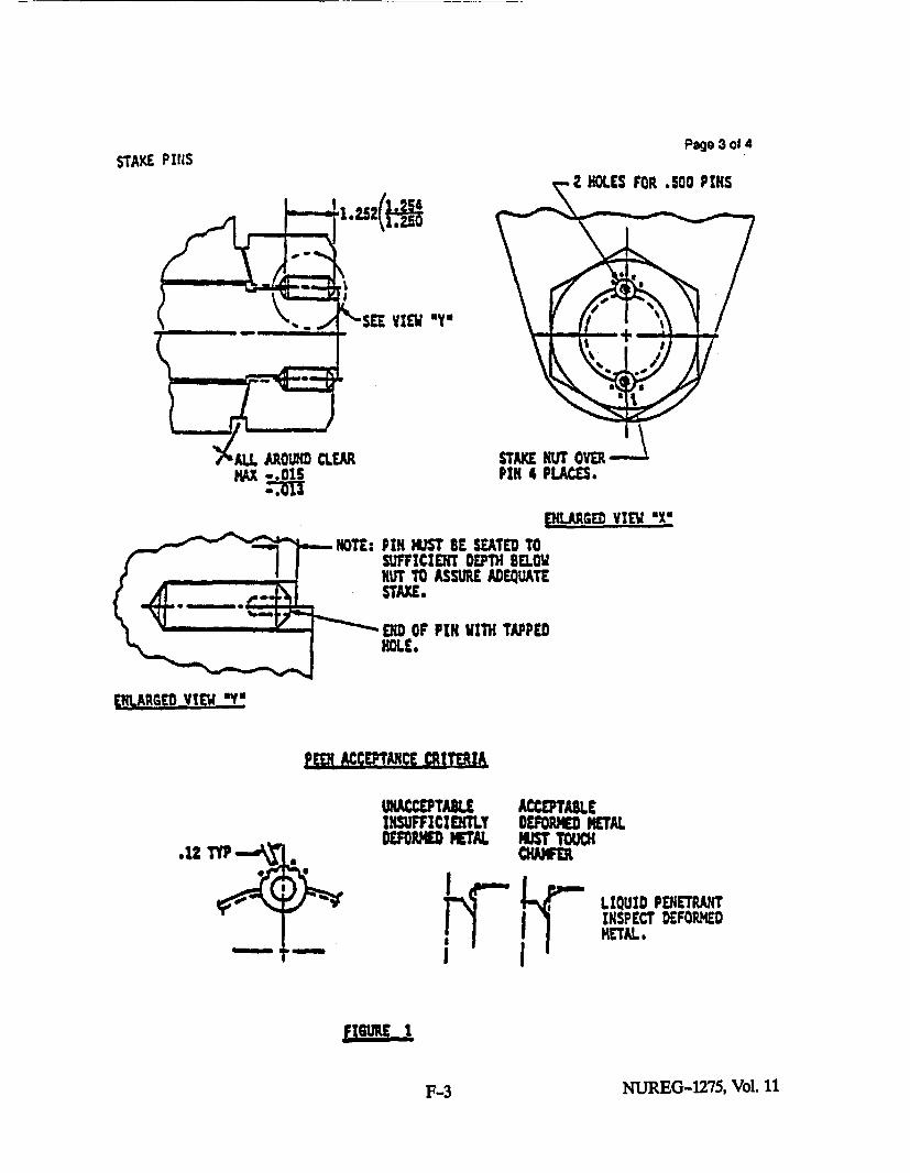
STAKE PINiSPage 3 ot 4
2 HOLES FOR .500 PFIS
VIEW "Y"
STAKE NUT OVER --PIN 4 PLACES.
ENUJGED VIEW "%*
PIN MUST' BE SEATED TOSUFFICIENT DEPTH BELOWNOT TO ASSURE ADEQUATESTAKE.
-END OF PIN WITH TAPPEDHOLE.
ENARGID VtEW_ s~'f
.12
PMI ACCEPACE -CRITERIA
LNACCEPTADLE ACCEPTABLEINLUFFIN C IlLY OEOSiG METALDEFORNME[ METAL MUST TOUCH
INSPNETJ
110 PENETRANT[ECT DEFORMED9.
uw-ww &•
flow I
F-3 NUREG-1275, Vol. 11

OMM 108Page 4 of 4
5152
BELLVILLEWASHERS
PEEN TO RETAIN 53
55
WITH STOP VALVE HOT AND WIDE OPEN. COMPRESS,BELLEVILLE WASHERS (IT. 34) BY USE OF ADJUSTINGSCREW (IT. SO) UNTIL STOP VALVE JUST STARTS TOMOVE IN THE CLOSED DIRECTION, THEN BACK OFFADJUSTING SCREW 60* LOXK WITH HUT (IT. 52)
0BACKSEAT
AT ASSEI4BLY CHECK THAT CLAPPER VALVE IS BACK-SEATEDAGAINST STOP WIEN IN OPEN POSITION AND THAT SERVO
-CLAPPER VALVE ABOVESTEAM FLOW WHEN
FIGURE 2
NUREG-1275, Vol. 11 F-4

NRC FORM 335 U.S. NUCLEAR REGULATORY COMMISSION 1. REPORT NUMBER(2-) (Assigned by NRC, Add Vol.,NRCM 1102, 8upp., Rev., and Addendum Num-
3201, 3202 BIBLIOGRAPHIC DATA SHEET bre, If any.)
(Sag Instructions on the reverse) NUREG-1275, Vol. 112.TITLE AND SUBTITLE
Operating Experience Feedback Report--Trbine-Generator Overspeed 3. DATE REPORT PUBLISHED
Protection Systems MONTH YEAR
Com eria PwerRectrsApril 1995Commercial Power Reactors 4. FIN OR GRANT NUMBER
•. AUTHOR(S) 6. TYPE OF REPORT
H. L Ornstein Technical
7. PERIOD COVERED (Inclusive Dates)
1950-1994
8. PERFORMING ORGANIZATION - NAME AND ADDRESS (If NRC, provide Division, Office or Region, U.S. Nuclear Regulatory CommlssIon, and
mailing address; If contractor, provide name and mailing address.)
Safety Programs DivisionOffice for Analysis and Evaluation of Operational DataU.S. Nuclear Regulatory CommissionWashington, DC 20555-0001
9. SPONSORING ORGANIZATION - NAME AND ADDRESS (If NRC, type "Same as above"; If contractor, provide NRC Division, Office or Region,
U. S. Nuclear Regulatory Commission, and mailing address,)
Same as 8 above.
10. SUPPLEMENTARY NOTES
11. ABSTRACT (200 words or less)
The report presents the results of the U.S. Nuclear Regulatory Commission's Office for Analysis and Evaluation of Opera-tional Data (AEOD) review of operating experience of main turbine-generator overspeed and overspeed protection sys-tems. AEOD's study provides insight into the shortcomings in the design, operation, maintenance, testing, and human fac-tors associated with turbine overspeed protection systems. It includes an indepth examination of the turbine overspeed eventthat occurred on November 9, 1991, at the Salem Unit 2 Nuclear Power Plant. It also provides information concerning ac-tions taken by other utilities and the turbine manufacturers as a result of the Salem overspeed event. AEOD's study re-viewed operating procedures and plant practices. It noted differences between turbine manufacturer designs and recom-mendations for operations, maintenance, and testing, and also identified significant variations in the manner that individualplants maintain and test their turbine overspeed protection systems.
12. KEY WORDSIDESCRIPTORS (List words or phrases that will assist researchers In locating the report.) 13. AVAILABILITY STATEMENT
Turbine, overspeed (OPC), electrohydraulic system, EHC, missile, control system, Unlimited
Regulatory Guide 1.115, RG 1.115, General Design Criterion 4, GDC 4, turbine- 14. SECURITY CLASSIFICATION
generator, Salem-2, solenoid valve, solenoid operated valve, SOV, common mode (This Page)
failure, admission valve, bypass valve, OPC, ET, governor, hammer, AST, SERT, Unclassifiedfront standard, hand trip, precursor, TIL, fire, flood, vibration, A1T, CAL, AIB (This Report)
Unclassified15. NUMBER OF PAGES
16. PRICE
NRC FORM 335 (2-89)


Federal Recycling Program

NUREG-1275, Vol. 11 OPERATING EXPERIENCE FEEDBACK REPORT-TURBINE-GENERATOROVERSPEED PROTECTION SYSTEMS
UNITED STATESNUCLEAR REGULATORY COMMISSION
WASHINGTON, D.C. 20555-0001
APRIL 1995
1PECgIAL, EouTI~T-1-rASS PATEPOSTAGEA,!ND FEES PAID
USNRCPEWMrt~q. ",7
OFFICIAL BUSINESSPENALTY FOR PRIVATE USE, $300
I