research of the cnc lathes with adjustable positioning ... · the numerical control lathe with...
TRANSCRIPT

Research of the CNC Lathes with Adjustable Positioning Support Device
Jin Kui Dalian Vocational & Technical College, China, 116037
Keywords: Adjustable device design; Positioning accuracy; Install the efficiency
Abstract: The inaccurate of workpiece positioning, processing precision is not high enough as expected and low production efficiency are the main problems in batch processing of long axis parts. Due to these problems, this paper has designed an adjustable positioning device for CNC lathe and it has been proved to be able to solve the above problems in practical application.
1. Introduction As the rapid development of science and technology nowadays, human civilization has an
unprecedented leap. Mechanization replaces manual production has become a global trend. All walks of life in society, including transportation, agriculture and animal husbandry, petroleum, chemical, coal, electric power, textile, electronics, communications, medical, military and so on, are inseparable from kinds of machinery and equipment, which are provided by the mechanical manufacturing industry. In the knowledge system of mechanical manufacture field, mechanical manufacturing technology focuses on the research on the technology in the process of manufacturing. And machine tool fixture design focuses on: work piece clamping in the machine tool. Compared with large and medium-sized enterprises, small and medium-sized enterprises can take the advantage of using the cheapest cost of production to create the highest profits to survive and develop, which has a crucial link with craft process in products manufacturing. Through the reasonable arrangement process route and the use of combination fixture to improve the production efficiency and reduce the production cost is the most direct and effective method.
Through the long and medium axis in the use of assistive devices to complete processing, this article illustrates the reasonable use of assistive devices can not only improve the product processing precision and the production efficiency, but also greatly reduce the labor intensity of the practitioner.
2. The Traditional Processing Form of Long and Medium Axis In the field of mechanical processing, to achieve the aim of improving production efficiency,
numerical control lathe usually adopts turning soft claw to complete each of the clamping work pieces positioning when processes bulk short axis artifacts. However, in the batch processing of long and medium axial parts, (for shape for turning 10 < length to diameter ratio < 15 minimum diameter, work piece is greater than 20 mm blank for forgings, bar or cold drawn material), the clamping part needs to extend into the hollow shaft mouth due to the size of work piece is too long. Therefore, by processing the soft claw into steps claw to complete the clamping position of work piece each time can't satisfy the processing requirements of work piece. The length of the short three jaw clamping work piece is 5 ~ 20 mm. Due to the size of the production produced by program is relatively the same to the machine origin, after each clamping in order to guarantee the correct length size, reduce the axial error of work piece, the operator usually measures position with caliper or ruler during processing, which greatly increases the labor intensity and reduces the production efficiency The same problem also exists in the engine lathe (Fig. 1).
2018 7th International Conference on Advanced Materials and Computer Science (ICAMCS 2018)
Published by CSP © 2018 the Authors 52

Figure 1 The traditional processing form of long and medium axis
According to the above problems in the existing technology, the purpose of this paper is to study and design a new type of the positioning supporting device in numerical control lathe to solve the existing problem in the existing technology: inaccurate positioning in batch processing, defects in machining accuracy and position on batch processing of long and medium axial work piece, low production efficiency, is very necessary.
3. The Structure of Adjustable Positioning Support Device: The numerical control lathe with adjustable positioning support device in this paper, is made up
of the floating axis 1, 2, and guide screw spindle and tailstock taper hole with the sleeve of 3, 4 of cylindrical helical spring lock the socket head cap screw, rear cover 5, 6, positioning column 7 (Fig. 2).
The characteristics: the back cover five fixed by threaded connection with the main shaft and the tailstock taper hole on the backend of sleeve 3 matched;1, 4, floating axis of cylindrical helical spring according to the sequence in the cooperate with spindle and tailstock taper hole of the sleeve 3 hole, then positioning feature column load floating shaft taper hole 1.1 7.1;Floating shaft and sleeve 3 holes for clearance fit, twisting back cover 5 under the effect of elastic cylindrical spiral compression spring 4 allows floating shaft extension forward, guide screw 2 cooperate with floating straight groove on the shaft 1, straight flute has played a guiding role, the lock on the socket head cap screw 6 and floating axis 1 straight groove cooperates, straight flute had fixed lock effect, limiting the floating shaft length.
Figure 2 The structure of adjustable positioning support device
4. The Use of Adjustable Positioning Device In this paper, processing, long axial parts in bulk, device used to role positioning: positioning
function first column 7 by mating surface load floating shaft taper hole 1.1 7.1, according to the work piece clamping length adjust floating shaft 1 scale length, let lock on the socket head cap screw 6 and floating axis 1 straight groove cooperates, straight flute had fixed lock effect, limit of the floating axis 1 scale length. Then will locate support device and the main shaft and the tailstock taper hole with the sleeve of 3 by Morse taper sleeve, sleeve into the headstock hollow spindle taper
53

hole so that it is fixed inside the spindle. Finally into the work piece, the work piece reference face and positioning column 7 joint positioning surface. Solve the problem of the accurate positioning of the work piece.
When processing finished work after the end, based on face after processing, measuring the depth of work pieces, according to the floating shaft 1 scale adjustment scale length, clamping socket head cap screw 6, limit floating shaft length. So as to solve the measurement of work piece axis dimension is difficult problem. At the same time solve the problem of the two end face parallelism (Fig. 3).
Figure 3 The use of adjustable positioning device
5. Examples On the basis of the above design, with the threaded shaft rod as the processing object, the
application of the adjustable positioning support device on the NC lathe is used to verify the actual processing.
As shown in Figure 4, the threaded shaft rod is mass production, both ends of the threaded shaft need to be machined. Although the MM Outer Circle Dimension Tolerance is strict and the surface roughness is ra1.6m, but the real difficulty which is needed to be considered in the processing is how to ensure that the total length of the thread shaft is 205±0.02mm, and repeated positioning problem in second clamping processing of each threaded shaft. Because the base of the wheelbase is far away, so that the operator will generally use caliper or ruler to measure positioning after each clamping of the workpiece, in order to ensure that the length of the correct size, reduce the axial error. The thread shaft bar itself has a 205±0.02 size, which makes the product processing quality difficult to Guarantee.
Figure 4 threaded shaft rod
Through the analysis of the structure of the machining and the parts themselves, we believe that the main cause of the 205±0.02 size instability of the screw shaft rod is that the positioning error is not accurate during each clamping process. The difference in the position of the two threads is the result of inconsistent positioning of each clamping and the second Turn-around clamping. 5.1 Key Issue One: Workpiece Positioning Method.
The device is used for positioning when the threaded shaft rod is processed in bulk. First, put the positioning function column through the mating surface into the floating shaft cone hole, and then adjust the length of the floating shaft extension according to the workpiece clamping length, and
54
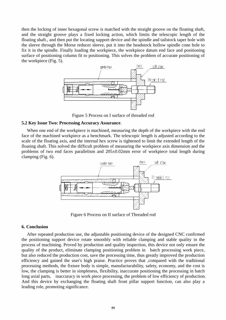
then the locking of inner hexagonal screw is matched with the straight groove on the floating shaft, and the straight groove plays a fixed locking action, which limits the telescopic length of the floating shaft., and then put the locating support device and the spindle and tailstock taper hole with the sleeve through the Morse reducer sleeve, put it into the headstock hollow spindle cone hole to fix it in the spindle. Finally loading the workpiece, the workpiece datum end face and positioning surface of positioning column fit to positioning. This solves the problem of accurate positioning of the workpiece (Fig. 5).
Figure 5 Process on I surface of threaded rod
5.2 Key Issue Two: Processing Accuracy Assurance. When one end of the workpiece is machined, measuring the depth of the workpiece with the end
face of the machined workpiece as a benchmark. The telescopic length is adjusted according to the scale of the floating axis, and the internal hex screw is tightened to limit the extended length of the floating shaft. This solved the difficult problem of measuring the workpiece axis dimension and the problems of two end faces parallelism and 205±0.02mm error of workpiece total length during clamping (Fig. 6).
Figure 6 Process on II surface of Threaded rod
6. Conclusion After repeated production use, the adjustable positioning device of the designed CNC confirmed
the positioning support device rotate smoothly with reliable clamping and stable quality in the process of machining. Proved by production and quality inspection, this device not only ensure the quality of the product, eliminate clamping positioning problem in batch processing work piece, but also reduced the production cost, save the processing time, thus greatly improved the production efficiency and gained the user's high praise. Practice proves that ,compared with the traditional processing methods, the fixture body is simple, manufacturability, safety, economy, and the cost is low, the clamping is better in simpleness, flexibility, inaccurate positioning the processing in batch long axial parts, inaccuracy in work piece processing, the problem of low efficiency of production. And this device by exchanging the floating shaft front pillar support function, can also play a leading role, promoting significance.
55

References [1] Xu Hao. Mechanical Design Manual [K]. Mechanical Industry Publishing House, 2014. [2] Liu Shouyong. Mechanical Manufacturing Technology and Machine Tool Fixture [M]. Mechanical Industry Publishing House, 2008. [3] Li Changnian. Machine Tool Fixture Design and Manufacturing [M]. Beijing: Mechanical Industry Press, 2007. [4] Lin Wenhuan. Machine Tool Fixture Design [M]. Beijing: National Defense Industry Press, 2010. [5] Amritsar, Mechanical Design Parts and Utility Atlas [M]. Mechanical Industry Press, 2013.
56