residual life concepts applied to hv sf6-gas insulated ... · -hv switch gear. ¾. maintenance...
TRANSCRIPT

Copyright© Siemens AGEnergy Sector – Power Transmission High Voltage SubstationsPeter Glaubitz
Residual life concepts applied to HV SF6-gas insulated switchgear considering tightness
EPA‘s 2009 Workshop on SF6-emission reduction strategies Phoenix, Arizona; February 4-5, 2009

Page 2Copyright© Siemens AG
Energy Sector - Power Transmission High Voltage SubstationsPeter Glaubitz
Introduction
Determinant factors for SF6-tightness in the past and today
Aged equipment and residual life-time
SF6-monitoring
Characteristics of SF6-leaks
Maintenance strategies
Maintenance activities
User experience
SF6-GIS concepts regarding tightness
Conclusion
Content

Page 3Copyright© Siemens AG
Energy Sector - Power Transmission High Voltage SubstationsPeter Glaubitz
IntroductionMore than 40 years of operational life-time experience
The equipment is gastight
Since more than 40 years in serviceBerlin, UW Wittenau, Vattenfall Europe, 123 kV, 31.5 kA
1968
State-of-the-art 145 kV, 40kA GIS
2009

Page 4Copyright© Siemens AG
Energy Sector - Power Transmission High Voltage SubstationsPeter Glaubitz
DesignMaterial Type testingProduction and installation/commissioning Operation, maintenance, serviceInternational standards
......and trained people for the development of following generation of new equipment as well as experienced people, because of the expected long life-time of the electric power equipment
Determinant factors for SF6-gas tightness and therefore a major factor for residual life of electric power equipment

Page 5Copyright© Siemens AG
Energy Sector - Power Transmission High Voltage SubstationsPeter Glaubitz
Equipment design – materialSF6-Tightness of aluminium vessels
Best qualityDecade-long tightness
State-of-the-art productionProcess optimizationReliable partner
Machining PaintingCasting Design
state-of-the-art software
Beside requirements on SF6-tightness, pressure vessel regulations apply as well

Page 6Copyright© Siemens AG
Energy Sector - Power Transmission High Voltage SubstationsPeter Glaubitz
Automatic integral gas tightness routine test of complete switchgear vesselswith Helium (instead of SF6) guarantees the highest tightness
Equipment SF6-tightness Routine testing of vessels

Page 7Copyright© Siemens AG
Energy Sector - Power Transmission High Voltage SubstationsPeter Glaubitz
O-ring MaterialO-ring Level of filling / pressingSealing- / groove surface High quality of the surfaceFlange surface Corrosion protection
Sealing systems like this assure the tightness of the GIS for decades. However, especially for outdoor equipment this must be supported by an effective corrosion protection
1 Sealing- / groove surface 2 Pressure vessel3 Flange with sealing surface4 Bolt hole 5 O-ring6 Flange with sealing groove
Sealing systemsDesign and material
Static SF6-sealing systems

Page 8Copyright© Siemens AG
Energy Sector - Power Transmission High Voltage SubstationsPeter Glaubitz
1 Bearing 2 Bearing 3 Radial sealing packages
Radial sealing packages are an import factor for SF6-tightness of the GIS
1
23
Dynamic SF6-sealing systems
Sealing systems Design and material

Page 9Copyright© Siemens AG
Energy Sector - Power Transmission High Voltage SubstationsPeter Glaubitz
8DN92
High voltage GIS Type testing on SF6-tightness
Tightness tests of complete GIS and also components according to IEC are part of the quality assurance process (closed pressure systems)
The tightness of SF6-GIS can be confirmed nowadays during type testing (integral measuring process with state-of-the-art measurement devices) in the range of <0,01%/year/gas compartment compared with the required <0,5%/year/gas compartment in the relevant standards

Page 10Copyright© Siemens AG
Energy Sector - Power Transmission High Voltage SubstationsPeter Glaubitz
Component design development Cast-Resin partitions
Beside „external“ SF6-tightness „internal“ SF6-tightness
(between 2 gas compartments) has to be assured as well
Production and testing in the factory (including gas permissible
partitions and other insulating parts)

Page 11Copyright© Siemens AG
Energy Sector - Power Transmission High Voltage SubstationsPeter Glaubitz
Production, installation & commissioningSF6-Leakage detection
In the factoryAll assembled connectionsAssured leakage rate of <0,5%/a/gascompartment
On siteAll made connections Assured leakage rate of <0,5%/a/gas compartment
Special care has to be taken during transportation from the factory to the site
Page 12Copyright© Siemens AG
Energy Sector - Power Transmission High Voltage SubstationsPeter Glaubitz
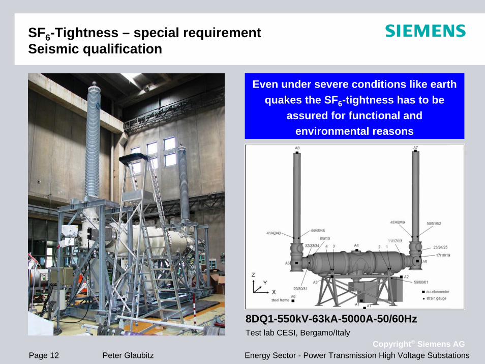
SF6-Tightness – special requirement Seismic qualification
8DQ1-550kV-63kA-5000A-50/60HzTest lab CESI, Bergamo/Italy
Even under severe conditions like earth quakes the SF6-tightness has to be
assured for functional and environmental reasons

Page 13Copyright© Siemens AG
Energy Sector - Power Transmission High Voltage SubstationsPeter Glaubitz
SF6/N2 Tightness – special requirement Gas Insulated Lines
Experience on SF6-tightness in
various solutions for GIL transmission
projects
Inside the GIL for example: 80% N2 & 20% SF6

Page 14Copyright© Siemens AG
Energy Sector - Power Transmission High Voltage SubstationsPeter Glaubitz
Aged equipmentSF6-Tightness and residual life-time of equipment
40
Refurbishment
SF6-
leak
s (n
umbe
r)
*) Usually transportation issues and handling irregularities on site
Installation/commissioning*
Maintenance*
0
Today
Time of operation (years)
Currently we do not know this moment
0 2010 30 50
Date for a systematical change of tightness is not known yet Refurbishment might extent the life-time of the equipment
Today all installed equipment is still gas tight

Page 15Copyright© Siemens AG
Energy Sector - Power Transmission High Voltage SubstationsPeter Glaubitz
SF6-Monitoring
The alarm values are based on the electrical functionality of the equipment andused for SF6-leakage indications as well
A SF6-gas monitoring system can be used for early leakage detection and trend analysis of leakage size
conventionally not monitored area
density [g/l]
pres
sure
[bar
abs
.]
temperature [°C]
1 Operating pressure: 5,5 bar abs.2 „Loss of SF6“: 4,7 bar abs.3 „General lockout SF6„: 4,5 bar abs.
(all values at +20°C)
1
2
3
SF6-gas monitoring area(between blue line and line 2 )
1 SF6-density line
2 1. Stage alarm
3 2. Stage alarm
Operational clearance zone (between line 1 and blue line)

Page 16Copyright© Siemens AG
Energy Sector - Power Transmission High Voltage SubstationsPeter Glaubitz
SF6-Gas monitoring systemDensity, trend curves, trend forecast
Hardware-structure (example)
(Optional: density calculation of pressure and temperature)
...... Example:Analogue inputs 4…20mA for 366 gas compartments
Trend forecast value
Stations Control Unit
Coupling Elements
Analogue Input Elements
HMIControl Unit
HMI+ trend curves (example)

Page 17Copyright© Siemens AG
Energy Sector - Power Transmission High Voltage SubstationsPeter Glaubitz
Characteristics of SF6-leaks (appear seldom)
Processing usually very slow (individual cases like wrong mounted O-ring, cast aluminium vessel)
Enough time to react before 1st stage or 2nd stage alarm appears
Processing very fast (individual case) as component failure, ambient circumstances, malicious damage
Pressure inside gas compartment drops to ambient pressure level
Due to corrosion in case of insufficient protective measures during installation (outdoor)
Can process as a little or big leak
Due to „ageing“At this moment in time not reached
Regardless the type of SF6-leak, it has to be repaired as soon as possible after detection

Page 18Copyright© Siemens AG
Energy Sector - Power Transmission High Voltage SubstationsPeter Glaubitz
Maintenance strategies in general forSF6-HV switch gear
Maintenance steps:Inspection: determining and assessing the actual conditionServicing: preserving the desired conditionRepair: restoring the desired conditionReplacement: replacing equipment or systems which are no longer usable
Several maintenance strategies are used in electrical systems:Corrective Time-basedCondition-basedReliability-centeredRisk-based
Aim of all maintenance activities: maintenance costs should be minimized, the intervals between maintenance enlarged, the availability of the equipment increased, environmental issues considered SF6

Page 19Copyright© Siemens AG
Energy Sector - Power Transmission High Voltage SubstationsPeter Glaubitz
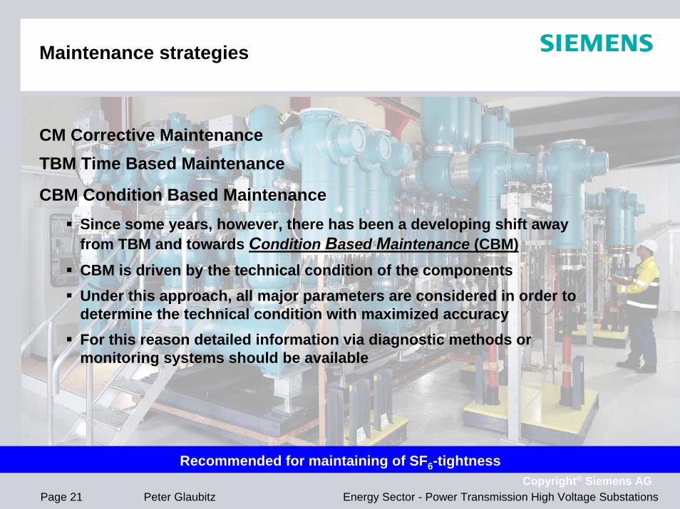
Maintenance strategies
CM Corrective Maintenance
In a Corrective Maintenance (CM) strategy, replacement or repair is performed only if a failure occurred
In case where equipment investment costs are low and a fault will have only a minor effect, this procedure may result in the lowest overall costs
This strategy will be mainly used in systems with lower voltages
Only severe failure on certain type of equipment will influence the procedure
Not recommended for maintaining of SF6-tightness

Page 20Copyright© Siemens AG
Energy Sector - Power Transmission High Voltage SubstationsPeter Glaubitz
Maintenance strategies
CM Corrective MaintenanceTBM Time Based Maintenance
A Time Based Maintenance (TBM) strategy featuring predefined intervals rooted in empirical feedback, where components are replaced after a specified period of use, has been practiced as the usual maintenance strategy in electrical power systems for many yearsThis approach generally produces satisfactory resultsIt will not, however, be the most cost-effective option in all cases, since the components will usually not remain in operation up to the end of the life-time which is possible
Partly recommended for maintaining of SF6-tightness
Page 21Copyright© Siemens AG
Energy Sector - Power Transmission High Voltage SubstationsPeter Glaubitz
Maintenance strategies
CM Corrective MaintenanceTBM Time Based Maintenance
CBM Condition Based MaintenanceSince some years, however, there has been a developing shift away from TBM and towards Condition Based Maintenance (CBM) CBM is driven by the technical condition of the components Under this approach, all major parameters are considered in order to determine the technical condition with maximized accuracy For this reason detailed information via diagnostic methods or monitoring systems should be available
Recommended for maintaining of SF6-tightness

Page 22Copyright© Siemens AG
Energy Sector - Power Transmission High Voltage SubstationsPeter Glaubitz
Maintenance strategies
CM Corrective MaintenanceTBM Time Based Maintenance
CBM Condition Based Maintenance
RCM Reliability-Centered MaintenanceA fourth strategy, which additionally include a reliability-based component, is in use The aim of this approach is to include the influence on the importance of the equipment in the network and the actual condition of the equipment
A maintenance strategy is referred to as Reliability-Centered Maintenance (RCM) and it has to be noticed that this RCM-method is different considering other RCM applications which consider equipment only
Partly recommended for maintaining of SF6-tightness

Page 23Copyright© Siemens AG
Energy Sector - Power Transmission High Voltage SubstationsPeter Glaubitz
Maintenance strategies
CM Corrective MaintenanceTBM Time Based Maintenance
CBM Condition Based Maintenance
RCM Reliability-Centered Maintenance
RCM is based on experiences and consequences of failures
failure causes and failure modes for each component have to be identified and than to be subjected to a failure mode effective analyses (FMEA) advantage of this method is expected to have cost savings in preventive maintenance and that the costs of implementation willprovide a pay back within one year (according EPRI) method depends on the correct judgment of failures with FMEA
Partly recommended for maintaining of SF6-tightness

Page 24Copyright© Siemens AG
Energy Sector - Power Transmission High Voltage SubstationsPeter Glaubitz
Maintenance strategies
CM Corrective MaintenanceTBM Time Based Maintenance
CBM Condition Based Maintenance
RCM Reliability-Centered Maintenance
RBM Risk Based Maintenance
Motto: “operate until it breaks”Measure for this method is the Life Cycle Cost LCCLCC = Acquisition Cost + Ownership Cost + Disposal CostSaving money for maintenanceSaving money for diagnosis/monitoringHowever… risk of failure, risk of cost for unplanned unavailability, outage cost and risk of SF6-emission
Not recommended for maintaining of SF6-tightness

Page 25Copyright© Siemens AG
Energy Sector - Power Transmission High Voltage SubstationsPeter Glaubitz
Maintenance strategy to assure SF6-tightness and to extend the life-time of the equipment
Implementation of maintenance strategy for the equipment -in general- and tightness in particular Gives guidance to end of life decision and has a significant impact on the life cycle cost of the assets
Favourite regarding tightness under environmental aspects

Page 26Copyright© Siemens AG
Energy Sector - Power Transmission High Voltage SubstationsPeter Glaubitz
To be checked quantitatively: SF6-pressure gauge, SF6-dew point, SF6-acidity, SF6-density/pressure switch settings, SF6-trend analysis monitoring
To be checked visually: bursting disks, any type of SF6-gas piping, corrosion at bolted flange enclosure joints and other SF6-related components, particularly on outdoor equipment, damaged or degraded seals, adherence of dust or other foreign material to seals, porosity in enclosure castings or welds, painting
Avoid openings, take care when opening measuring connections or gas compartments (e.g. for filter material change)
Use original spare parts only
Contact OEM for further information/clarification
Maintenance activities to assure SF6-tightness

Page 27Copyright© Siemens AG
Energy Sector - Power Transmission High Voltage SubstationsPeter Glaubitz
The continuous life-time extension of GIS equipment regarding SF6-tightness and a very low SF6-emission was and can be reached by:
Identifying of small SF6-leaks and immediate repair (any type of monitoring)
Fingerprint of equipment (can be done together with OEM)
Improvement of maintenance strategy (less openings)
continuous training of staff
using state-of-the-art equipment and measuring devices (observing permanently the market)
User experience

Page 28Copyright© Siemens AG
Energy Sector - Power Transmission High Voltage SubstationsPeter Glaubitz
SF6-GIS-concepts for life-time extension regarding tightness and low SF6-emission
Since the implementation of the GIS-technology almost 5 decades ago, manufactures have supported theextension of the life time of installed equipment and continuously improve the design of the GIS
State-of-the-art GIS technologyIn the past

Page 29Copyright© Siemens AG
Energy Sector - Power Transmission High Voltage SubstationsPeter Glaubitz
Implementation of adequatemaintenance strategy for aged equipment
Evaluation of each SF6-leakagefor systematical or individual failure
Gas tight equipment and low SF6-emission reduce life-cycle costs
Residual Life of equipment goesin line with low SF6-emission
For end-of-life procedures, SF6has to be kept in a closed cycle
Conclusion

Page 30Copyright© Siemens AG
Energy Sector - Power Transmission High Voltage SubstationsPeter Glaubitz
Peter GlaubitzTel. +49 9131 7 35010eMail [email protected]
Thank you for your attention!
GIS Lead-Factory Berlin, Germany