rexroth indracontrol edition 02 vdp 08.3/40.3 operator
TRANSCRIPT

Project Planning Manual
Electric Drivesand Controls Pneumatics Service
Linear Motion and Assembly TechnologiesHydraulics
Rexroth IndraControlVDP 08.3/40.3Operator Terminal
R911328472Edition 02

Rexroth IndraControlVDP 08.3/40.3Operator Terminal
Project Planning Manual
DOK-SUPPL*-VDP*08.3***-PR02-EN-P
RS-330926ae6b58670e0a6846a001cc849a-2-en-US-8
This documentation describes the operator terminals IndraControl VDP 08.3and IndraControl VDP 40.3 and the Y repeater available as accessories.
Edition Release Date Notes
120-2101-B310/EN -01 05.2009 First edition120-2101-B310/EN -02 02.2010 Second edition
Copyright © Bosch Rexroth AG 2009Copying this document, giving it to others and the use or communication of thecontents thereof without express authority, are forbidden. Offenders are liablefor the payment of damages. All rights are reserved in the event of the grant ofa patent or the registration of a utility model or design (DIN 34-1).
Validity The specified data is for product description purposes only and may not bedeemed to be guaranteed unless expressly confirmed in the contract. All rightsare reserved with respect to the content of this documentation and the availa‐bility of the product.
Published by Bosch Rexroth AGBgm.-Dr.-Nebel-Str. 2 ■ 97816 Lohr am Main, GermanyPhone +49 (0)93 52/ 40-0 ■ Fax +49 (0)93 52/ 40-48 85http://www.boschrexroth.com/Dept. DCC/EAY2 (CS)Dept. DCC/EAP1 (HB/CS)
Note This document has been printed on chlorine-free bleached paper.
Title
Type of Documentation
Document Typecode
Internal File Reference
Purpose of Documentation
Record of Revision
Bosch Rexroth AG DOK-SUPPL*-VDP*08.3***-PR02-EN-P Rexroth IndraControl VDP 08.3/40.3 Operator Terminal
Table of ContentsPage
1 System Presentation...................................................................................................... 51.1 Brief Description of the VDP 08.3/40.3 Operator Terminals ................................................................. 51.2 Variants................................................................................................................................................... 51.2.1 Characteristic Features....................................................................................................................... 51.2.2 Displays with Touch Screen and Keys................................................................................................ 51.2.3 VDP 08.3 ............................................................................................................................................ 61.2.4 VDP 40.3............................................................................................................................................. 71.3 Accessories............................................................................................................................................ 71.4 Commissioning....................................................................................................................................... 7
2 Important Instructions on Use ....................................................................................... 92.1 Appropriate Use ..................................................................................................................................... 92.1.1 Introduction.......................................................................................................................................... 92.1.2 Areas of Use and Application.............................................................................................................. 92.2 Inappropriate Use................................................................................................................................. 10
3 Safety Instructions for Electric Drives and Controls .................................................... 113.1 Definitions of Terms.............................................................................................................................. 113.2 General Information.............................................................................................................................. 123.2.1 Using the Safety Instructions and Passing Them on to Others......................................................... 123.2.2 Requirements for Safe Use............................................................................................................... 123.2.3 Hazards by Improper Use.................................................................................................................. 133.3 Instructions with Regard to Specific Dangers....................................................................................... 143.3.1 Protection Against Contact with Electrical Parts and Housings......................................................... 143.3.2 Protective Extra-Low Voltage as Protection Against Electric Shock ................................................ 153.3.3 Protection Against Dangerous Movements....................................................................................... 153.3.4 Protection Against Magnetic and Electromagnetic Fields During Operation and Mounting.............. 173.3.5 Protection Against Contact With Hot Parts........................................................................................ 173.3.6 Protection During Handling and Mounting......................................................................................... 173.3.7 Battery Safety.................................................................................................................................... 183.3.8 Protection Against Pressurized Systems........................................................................................... 183.4 Explanation of Signal Words and the Safety Alert Symbol................................................................... 19
4 Technical Data............................................................................................................. 214.1 General Information.............................................................................................................................. 214.2 Voltage Supply...................................................................................................................................... 214.3 Ambient Conditions............................................................................................................................... 224.4 Standards............................................................................................................................................. 224.4.1 Used Standards................................................................................................................................. 224.4.2 CE Marking........................................................................................................................................ 23
Declaration of Conformity .............................................................................................................. 23Note for the Machine Manufacturer................................................................................................ 24
4.4.3 UL/CSA Certified............................................................................................................................... 24
DOK-SUPPL*-VDP*08.3***-PR02-EN-P Rexroth IndraControl VDP 08.3/40.3 Operator Terminal
Bosch Rexroth AG I/81
Table of Contents
Page
4.5 Wear Parts............................................................................................................................................ 254.6 Compatibility Test................................................................................................................................. 25
5 Dimensions, Installation and Wiring............................................................................. 275.1 Housing Dimensions............................................................................................................................. 275.1.1 General Information........................................................................................................................... 275.1.2 Housing Dimensions VDP 08.3......................................................................................................... 275.1.3 Housing Dimensions VDP 40.3......................................................................................................... 305.2 Mounting............................................................................................................................................... 325.2.1 Installation Notes............................................................................................................................... 325.2.2 Mounting............................................................................................................................................ 335.2.3 Attachment to a Standardized VESA Bracket................................................................................... 355.2.4 VESA Bracket.................................................................................................................................... 365.3 Electrical Wiring.................................................................................................................................... 37
6 Display and Operating Components............................................................................ 416.1 Backlight Switch-off.............................................................................................................................. 416.1.1 General Information........................................................................................................................... 416.2 Operating and Error Displays............................................................................................................... 416.3 Operation.............................................................................................................................................. 436.3.1 Key Positions..................................................................................................................................... 436.4 Touch Screen....................................................................................................................................... 43
7 Interfaces..................................................................................................................... 457.1 View on the Connector Panel............................................................................................................... 457.2 Interfaces at the VDP............................................................................................................................ 457.2.1 General Information........................................................................................................................... 457.2.2 Overview............................................................................................................................................ 457.2.3 S1 DIP Switch.................................................................................................................................... 46
Overview......................................................................................................................................... 46Operation Modes............................................................................................................................ 46
7.2.4 DC 24 V Voltage Supply.................................................................................................................... 477.2.5 XUSB Interfaces................................................................................................................................ 487.2.6 XSER Interfaces and XVID Interfaces............................................................................................... 49
CDI Interface.................................................................................................................................. 49XVID and XSER Assignment.......................................................................................................... 50XVID and XSER Markings.............................................................................................................. 50
7.3 Connection Keypad.............................................................................................................................. 507.3.1 Keypad.............................................................................................................................................. 507.3.2 Connection Scheme of the Keypad................................................................................................... 527.3.3 Pin Assignment of the Keypad.......................................................................................................... 52
8 Maintenance................................................................................................................ 558.1 General Information.............................................................................................................................. 558.2 LCD Display.......................................................................................................................................... 55
Bosch Rexroth AG DOK-SUPPL*-VDP*08.3***-PR02-EN-P Rexroth IndraControl VDP 08.3/40.3 Operator Terminal
II/81
Table of Contents
Page
9 Software....................................................................................................................... 579.1 Touch Screen Software........................................................................................................................ 579.2 M-Key-UpperClassFilter....................................................................................................................... 579.2.1 General Information........................................................................................................................... 579.2.2 Activation and Deactivation of the M-Key-UpperClassFilter.............................................................. 57
10 Y-Repeater................................................................................................................... 5910.1 General Information.............................................................................................................................. 5910.2 Housing Dimensions of the Y-Repeater............................................................................................... 5910.3 Switching Times Y-Repeater................................................................................................................ 6010.3.1 General Information........................................................................................................................... 6010.3.2 Switching Times without Devices on the USB Connections.............................................................. 6110.3.3 Switching Times with Devices on the USB Connections................................................................... 6110.4 Interfaces on the Y-Repeater................................................................................................................ 6110.4.1 View on the Connector Panel............................................................................................................ 6110.4.2 Description of the Interfaces.............................................................................................................. 6310.4.3 CDI Interfaces.................................................................................................................................... 6310.4.4 Cable connections and cable types allowed...................................................................................... 6310.4.5 24 V Supply Voltage and Digital 24 V Input ...................................................................................... 6410.5 Display Elements on the Y-Repeater.................................................................................................... 6510.5.1 LEDs on the Y-Repeater................................................................................................................... 6510.6 Connection of the Y-Repeater.............................................................................................................. 6610.6.1 Connection of the Y-Repeater (block diagram)................................................................................. 6610.6.2 Pin Assignment on the Y-Repeater................................................................................................... 6610.6.3 Connection of Two Operator Displays via the Y-Repeater................................................................ 6610.6.4 Connection of Four Operator Displays via Three Y-Repeaters......................................................... 67
11 Environmental Protection and Disposal ...................................................................... 6911.1 Environmental Protection...................................................................................................................... 6911.2 Disposal................................................................................................................................................ 69
12 Ordering Information.................................................................................................... 7112.1 Type Designation Code........................................................................................................................ 7112.1.1 General Information........................................................................................................................... 7112.1.2 VDP 08.3........................................................................................................................................... 7112.1.3 VDP 40.3........................................................................................................................................... 7212.2 Accessories.......................................................................................................................................... 7212.2.1 Y-Repeater........................................................................................................................................ 7212.2.2 External 24 V Power Supply Unit...................................................................................................... 7312.2.3 Uninterruptible Power Supply............................................................................................................ 7312.2.4 Connecting Cable for CDI Interface................................................................................................... 7312.2.5 Connecting Cable for USB Interface................................................................................................. 7412.2.6 USB Connecting Cables with Increased Noise Immunity.................................................................. 7412.2.7 Cable Grommets (Mounting/Sealing Kit)........................................................................................... 74
DOK-SUPPL*-VDP*08.3***-PR02-EN-P Rexroth IndraControl VDP 08.3/40.3 Operator Terminal
Bosch Rexroth AG III/81
Table of Contents

Page
13 Service and Support.................................................................................................... 77
Index............................................................................................................................ 79
Bosch Rexroth AG DOK-SUPPL*-VDP*08.3***-PR02-EN-P Rexroth IndraControl VDP 08.3/40.3 Operator Terminal
IV/81
Table of Contents

1 System Presentation1.1 Brief Description of the VDP 08.3/40.3 Operator Terminals
The VDP 08.3/40.3 operator terminals are passive operator and visualizationterminals. They form a PC based operator terminal when used with a controlcabinet PC equipped with a CDI interface. Currently, the VSB 40.3 and theVPB 40.3 devices are available as control cabinet PCs. The VDP 08.3/40.3operator terminals can be attached to a bracket with a VESA adapter, whereasthe control cabinet PC can be installed e.g. into a control cabinet. The datatransmission between control cabinet PC and a VDP 08.3/40.3 operator termi‐nal is carried out via the CDI interface. VDP 08.3/40.3 devices consist of arobust and single metal housing.
Y-Repeater A Y-repeater is an accessory to connect VDP devices to a control cabinet PC(see chapter 1.3 "Accessories" on page 7). The Y-repeater can be used toconnect two VDP devices to a control cabinet PC.The Y-repeater is described in chapter 10 "Y-Repeater" on page 59.
1.2 Variants1.2.1 Characteristic Features
The operator terminals are available in different variants, see type designationcode in chapter 12 "Ordering Information" on page 71. They differ in thedisplay size.
VDP 08.3 DP
Display 213.36 mm TFT (8.4")
Touch screen Yes
3 × keys1 x emergency stop button
Yes
Fig.1-1: Features VDP 08.3 device
VDP 40.3 DI
Display 381 mm TFT (15")
Touch screen Yes
3 × keys1 x emergency stop button
Yes
Fig.1-2: Features VDP 40.3 device
1.2.2 Displays with Touch Screen and KeysThe front panel with touch screen also consists of a 5 mm thick aluminum panelwith beveled edges. The front panel is integrated. The application software isoperated via the touch-sensitive interface of the display.
Danger of destruction of the touch screen ifoperated with inappropriate objects (e.g.screwdriver).
NOTICE
Operate the touch screen only with your finger or with a touch pen.
DOK-SUPPL*-VDP*08.3***-PR02-EN-P Rexroth IndraControl VDP 08.3/40.3 Operator Terminal
Bosch Rexroth AG 5/81
System Presentation
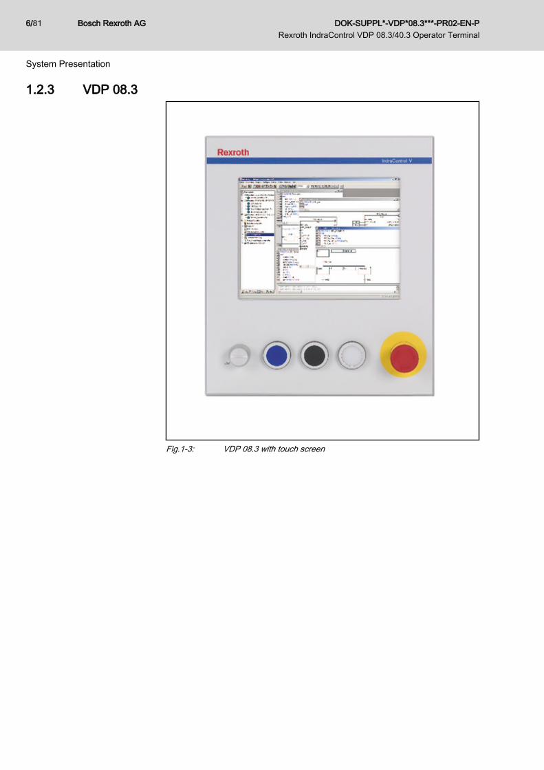
1.2.3 VDP 08.3
Fig.1-3: VDP 08.3 with touch screen
Bosch Rexroth AG DOK-SUPPL*-VDP*08.3***-PR02-EN-P Rexroth IndraControl VDP 08.3/40.3 Operator Terminal
6/81
System Presentation

1.2.4 VDP 40.3
Fig.1-4: VDP 40.3 with touch screen
1.3 AccessoriesUsing the Y-repeater (order code VAC01.1S-YD1-NNNN) that is provided asaccessories, two VDPs can be connected to a control cabinet PC. The Y-re‐peater can be cascaded. Therefore, three or more VDPs can be connected toa control cabinet PC. See also chapter 10 "Y-Repeater" on page 59.
1.4 CommissioningMount the device properly, see also chapter 5.2 "Mounting" on page 32.Connect the device to the control cabinet PC and apply the 24 V supply voltage.
DOK-SUPPL*-VDP*08.3***-PR02-EN-P Rexroth IndraControl VDP 08.3/40.3 Operator Terminal
Bosch Rexroth AG 7/81
System Presentation

Bosch Rexroth AG DOK-SUPPL*-VDP*08.3***-PR02-EN-P Rexroth IndraControl VDP 08.3/40.3 Operator Terminal
8/81
2 Important Instructions on Use2.1 Appropriate Use2.1.1 Introduction
Rexroth products represent state-of-the-art developments and manufacturing.They are tested prior to delivery to ensure operational safety and reliability.
Physical injury and material damage might re‐sult from an inappropriate use of the products!
WARNING
The products are designed for the use in an industrial environment and maytherefore only be used for the intended purpose. If they are not used as inten‐ded, situations causing personal injury as well as material damage can occur.
Bosch Rexroth disclaims as manufacturer any warranty, liability ordamages occurring due to inappropriate use of the products. Fur‐thermore, Bosch Rexroth is not paying any compensation. The useris responsible for any risks resulting from inappropriate use of theproducts.
Before using Rexroth products, the following requirements must be met to en‐sure appropriate use of the products:● Anyone handling one of the Rexroth products in any way has to read and
understand the respective safety-related guidelines as well as the instruc‐tions on appropriate use.
● Hardware products have to remain in their original state, i. e. no modifi‐cation regarding the design is allowed. Software products must not bedecompiled and their source codes must not be modified.
● Damaged or faulty products must not be implemented or put into opera‐tion.
● It must be ensured that the products are installed as specified in the doc‐umentation.
2.1.2 Areas of Use and ApplicationThe Rexroth VDP 08.3/40.3 displays are passive operating and visualizationterminals forming a PC-based machine operating terminal when used with anindustrial PC.
Danger of destruction of the device if not ex‐pressly stated accessories, add-on compo‐nents and other components, cables, conduits,software and firmware is used.
NOTICE
The VDP 08.3/40.3 displays may exclusively be used with the accessories andadd-on components specified in this documentation. Components not namedexpressly mentioned must neither be mounted nor connected. The same ap‐plies to cables and conduits.The products may only be operated with the expressly stated configurationsand component combinations as well as with the software and firmware whichis given and specified in the respective functional description.
Typical areas of application of the VDP 08.3/40.3 are:
DOK-SUPPL*-VDP*08.3***-PR02-EN-P Rexroth IndraControl VDP 08.3/40.3 Operator Terminal
Bosch Rexroth AG 9/81
Important Instructions on Use
● Handling systems and assembly systems● Packaging and food processing machines● Printing machines and paper converting machines● Machine tools● Wood processing machinesThe VDP 08.3/40.3 operator displays may only be operated under the assemblyconditions and installation conditions, in the specified position of applicationand under the specified ambient conditions (temperature, degree of protection,humidity, EMC etc.) given in this documentation.
2.2 Inappropriate UseThe application of VDP 08.3/40.3 that are not whithin the specicified areas ofapplication or under operating conditions deviating from the operating condi‐tions and technical data specified in the documentation are considered as"inappropriate".VDP 08.3/40.3 must not be used if ...● it is exposed to operating conditions that do not fulfill the ambient condi‐
tions specified. For instance, operation under water, in case of extremevariations of temperature or in extreme maximum temperatures is not al‐lowed.
● the intended applications have not expressly been allowed by Rexroth. Itis imperative that you also note the information given in the general noteson safety!
Bosch Rexroth AG DOK-SUPPL*-VDP*08.3***-PR02-EN-P Rexroth IndraControl VDP 08.3/40.3 Operator Terminal
10/81
Important Instructions on Use

3 Safety Instructions for Electric Drives and Controls 3.1 Definitions of Terms
Application Documentation Application documentation comprises the entire documentation used to informthe user of the product about the use and safety-relevant features for config‐uring, integrating, installing, mounting, commissioning, operating, maintaining,repairing and decommissioning the product. The following terms are also usedfor this kind of documentation: User Guide, Operation Manual, CommissioningManual, Instruction Manual, Project Planning Manual, Application Manual, etc.
Component A component is a combination of elements with a specified function, which arepart of a piece of equipment, device or system. Components of the electric driveand control system are, for example, supply units, drive controllers, mainschoke, mains filter, motors, cables, etc.
Control System A control system comprises several interconnected control components placedon the market as a single functional unit.
Device A device is a finished product with a defined function, intended for users andplaced on the market as an individual piece of merchandise.
Electrical Equipment Electrical equipment encompasses all devices used to generate, convert, trans‐mit, distribute or apply electrical energy, such as electric motors, transformers,switching devices, cables, lines, power-consuming devices, circuit board as‐semblies, plug-in units, control cabinets, etc.
Electric Drive System An electric drive system comprises all components from mains supply to motorshaft; this includes, for example, electric motor(s), motor encoder(s), supplyunits and drive controllers, as well as auxiliary and additional components, suchas mains filter, mains choke and the corresponding lines and cables.
Installation An installation consists of several devices or systems interconnected for a de‐fined purpose and on a defined site which, however, are not intended to beplaced on the market as a single functional unit.
Machine A machine is the entirety of interconnected parts or units at least one of whichis movable. Thus, a machine consists of the appropriate machine drive ele‐ments, as well as control and power circuits, which have been assembled fora specific application. A machine is, for example, intended for processing,treatment, movement or packaging of a material. The term "machine" also cov‐ers a combination of machines which are arranged and controlled in such a waythat they function as a unified whole.
Manufacturer The manufacturer is an individual or legal entity bearing responsibility for thedesign and manufacture of a product which is placed on the market in the in‐dividual's or legal entity's name. The manufacturer can use finished products,finished parts or finished elements, or contract out work to subcontractors.However, the manufacturer must always have overall control and possess therequired authority to take responsibility for the product.
Product Examples of a product: Device, component, part, system, software, firmware,among other things.
Project Planning Manual A project planning manual is part of the application documentation used tosupport the sizing and planning of systems, machines or installations.
Qualified Persons In terms of this application documentation, qualified persons are those personswho are familiar with the installation, mounting, commissioning and operationof the components of the electric drive and control system, as well as with thehazards this implies, and who possess the qualifications their work requires. Tocomply with these qualifications, it is necessary, among other things,
DOK-SUPPL*-VDP*08.3***-PR02-EN-P Rexroth IndraControl VDP 08.3/40.3 Operator Terminal
Bosch Rexroth AG 11/81
Safety Instructions for Electric Drives and Controls

1) to be trained, instructed or authorized to switch electric circuits and devicessafely on and off, to ground them and to mark them2) to be trained or instructed to maintain and use adequate safety equipment3) to attend a course of instruction in first aid
User A user is a person installing, commissioning or using a product which has beenplaced on the market.
3.2 General Information3.2.1 Using the Safety Instructions and Passing Them on to Others
Do not attempt to install and operate the components of the electric drive andcontrol system without first reading all documentation provided with the product.Read and understand these safety instructions and all user documentation priorto working with these components. If you do not have the user documentationfor the components, contact your responsible Bosch Rexroth sales partner. Askfor these documents to be sent immediately to the person or persons respon‐sible for the safe operation of the components.If the component is resold, rented and/or passed on to others in any other form,these safety instructions must be delivered with the component in the officiallanguage of the user's country.Improper use of these components, failure to follow the safety instructions inthis document or tampering with the product, including disabling of safety de‐vices, could result in property damage, injury, electric shock or even death.
3.2.2 Requirements for Safe UseRead the following instructions before initial commissioning of the componentsof the electric drive and control system in order to eliminate the risk of injuryand/or property damage. You must follow these safety instructions.● Bosch Rexroth is not liable for damages resulting from failure to observe
the safety instructions.● Read the operating, maintenance and safety instructions in your language
before commissioning. If you find that you cannot completely understandthe application documentation in the available language, please ask yoursupplier to clarify.
● Proper and correct transport, storage, mounting and installation, as wellas care in operation and maintenance, are prerequisites for optimal andsafe operation of the component.
● Only qualified persons may work with components of the electric drive andcontrol system or within its proximity.
● Only use accessories and spare parts approved by Bosch Rexroth.● Follow the safety regulations and requirements of the country in which the
components of the electric drive and control system are operated.● Only use the components of the electric drive and control system in the
manner that is defined as appropriate. See chapter "Appropriate Use".● The ambient and operating conditions given in the available application
documentation must be observed.● Applications for functional safety are only allowed if clearly and explicitly
specified in the application documentation "Integrated Safety Technolo‐gy". If this is not the case, they are excluded. Functional safety is a safety
Bosch Rexroth AG DOK-SUPPL*-VDP*08.3***-PR02-EN-P Rexroth IndraControl VDP 08.3/40.3 Operator Terminal
12/81
Safety Instructions for Electric Drives and Controls
concept in which measures of risk reduction for personal safety dependon electrical, electronic or programmable control systems.
● The information given in the application documentation with regard to theuse of the delivered components contains only examples of applicationsand suggestions.The machine and installation manufacturers must– make sure that the delivered components are suited for their individ‐
ual application and check the information given in this applicationdocumentation with regard to the use of the components,
– make sure that their individual application complies with the appli‐cable safety regulations and standards and carry out the requiredmeasures, modifications and complements.
● Commissioning of the delivered components is only allowed once it is surethat the machine or installation in which the components are installedcomplies with the national regulations, safety specifications and standardsof the application.
● Operation is only allowed if the national EMC regulations for the applica‐tion are met.
● The instructions for installation in accordance with EMC requirements canbe found in the section on EMC in the respective application documenta‐tion.The machine or installation manufacturer is responsible for compliancewith the limit values as prescribed in the national regulations.
● The technical data, connection and installation conditions of the compo‐nents are specified in the respective application documentations and mustbe followed at all times.
National regulations which the user must take into account● European countries: In accordance with European EN standards● United States of America (USA):
– National Electrical Code (NEC)– National Electrical Manufacturers Association (NEMA), as well as
local engineering regulations– Regulations of the National Fire Protection Association (NFPA)
● Canada: Canadian Standards Association (CSA)● Other countries:
– International Organization for Standardization (ISO)– International Electrotechnical Commission (IEC)
3.2.3 Hazards by Improper Use● High electrical voltage and high working current! Danger to life or serious
injury by electric shock!● High electrical voltage by incorrect connection! Danger to life or injury by
electric shock!● Dangerous movements! Danger to life, serious injury or property damage
by unintended motor movements!● Health hazard for persons with heart pacemakers, metal implants and
hearing aids in proximity to electric drive systems!● Risk of burns by hot housing surfaces!
DOK-SUPPL*-VDP*08.3***-PR02-EN-P Rexroth IndraControl VDP 08.3/40.3 Operator Terminal
Bosch Rexroth AG 13/81
Safety Instructions for Electric Drives and Controls

● Risk of injury by improper handling! Injury by crushing, shearing, cutting,hitting!
● Risk of injury by improper handling of batteries!● Risk of injury by improper handling of pressurized lines!
3.3 Instructions with Regard to Specific Dangers3.3.1 Protection Against Contact with Electrical Parts and Housings
This section concerns components of the electric drive and controlsystem with voltages of more than 50 volts.
Contact with parts conducting voltages above 50 volts can cause personaldanger and electric shock. When operating components of the electric driveand control system, it is unavoidable that some parts of these componentsconduct dangerous voltage. High electrical voltage! Danger to life, risk of injury by electric shock or seriousinjury!● Only qualified persons are allowed to operate, maintain and/or repair the
components of the electric drive and control system.● Follow the general installation and safety regulations when working on
power installations.● Before switching on, the equipment grounding conductor must have been
permanently connected to all electric components in accordance with theconnection diagram.
● Even for brief measurements or tests, operation is only allowed if theequipment grounding conductor has been permanently connected to thepoints of the components provided for this purpose.
● Before accessing electrical parts with voltage potentials higher than 50 V,you must disconnect electric components from the mains or from the pow‐er supply unit. Secure the electric component from reconnection.
● With electric components, observe the following aspects:Always wait 30 minutes after switching off power to allow live capacitorsto discharge before accessing an electric component. Measure the elec‐trical voltage of live parts before beginning to work to make sure that theequipment is safe to touch.
● Install the covers and guards provided for this purpose before switchingon.
● Never touch electrical connection points of the components while poweris turned on.
● Do not remove or plug in connectors when the component has been pow‐ered.
● Under specific conditions, electric drive systems can be operated at mainsprotected by residual-current-operated circuit-breakers sensitive to uni‐versal current (RCDs/RCMs).
● Secure built-in devices from penetrating foreign objects and water, as wellas from direct contact, by providing an external housing, for example acontrol cabinet.
Bosch Rexroth AG DOK-SUPPL*-VDP*08.3***-PR02-EN-P Rexroth IndraControl VDP 08.3/40.3 Operator Terminal
14/81
Safety Instructions for Electric Drives and Controls
High housing voltage and high leakage current! Danger to life, risk of injury byelectric shock!● Before switching on and before commissioning, ground or connect the
components of the electric drive and control system to the equipmentgrounding conductor at the grounding points.
● Connect the equipment grounding conductor of the components of theelectric drive and control system permanently to the main power supply atall times. The leakage current is greater than 3.5 mA.
● Establish an equipment grounding connection with a copper wire of across section of at least 10 mm2 (8 AWG) or additionally run a secondequipment grounding conductor of the same cross section as the originalequipment grounding conductor.
3.3.2 Protective Extra-Low Voltage as Protection Against Electric Shock Protective extra-low voltage is used to allow connecting devices with basic in‐sulation to extra-low voltage circuits.On components of an electric drive and control system provided by BoschRexroth, all connections and terminals with voltages between 5 and 50 voltsare PELV ("Protective Extra-Low Voltage") systems. It is allowed to connectdevices equipped with basic insulation (such as programming devices, PCs,notebooks, display units) to these connections. Danger to life, risk of injury by electric shock! High electrical voltage by incorrectconnection!If extra-low voltage circuits of devices containing voltages and circuits of morethan 50 volts (e.g., the mains connection) are connected to Bosch Rexrothproducts, the connected extra-low voltage circuits must comply with the re‐quirements for PELV ("Protective Extra-Low Voltage").
3.3.3 Protection Against Dangerous MovementsDangerous movements can be caused by faulty control of connected motors.Some common examples are:● Improper or wrong wiring or cable connection● Operator errors● Wrong input of parameters before commissioning● Malfunction of sensors and encoders● Defective components● Software or firmware errorsThese errors can occur immediately after equipment is switched on or evenafter an unspecified time of trouble-free operation.The monitoring functions in the components of the electric drive and controlsystem will normally be sufficient to avoid malfunction in the connected drives.Regarding personal safety, especially the danger of injury and/or property dam‐age, this alone cannot be relied upon to ensure complete safety. Until theintegrated monitoring functions become effective, it must be assumed in anycase that faulty drive movements will occur. The extent of faulty drive move‐ments depends upon the type of control and the state of operation.
DOK-SUPPL*-VDP*08.3***-PR02-EN-P Rexroth IndraControl VDP 08.3/40.3 Operator Terminal
Bosch Rexroth AG 15/81
Safety Instructions for Electric Drives and Controls
Dangerous movements! Danger to life, risk of injury, serious injury or propertydamage!A risk assessment must be prepared for the installation or machine, with itsspecific conditions, in which the components of the electric drive and controlsystem are installed.As a result of the risk assessment, the user must provide for monitoring func‐tions and higher-level measures on the installation side for personal safety. Thesafety regulations applicable to the installation or machine must be taken intoconsideration. Unintended machine movements or other malfunctions are pos‐sible if safety devices are disabled, bypassed or not activated.To avoid accidents, injury and/or property damage:● Keep free and clear of the machine’s range of motion and moving machine
parts. Prevent personnel from accidentally entering the machine’s rangeof motion by using, for example:– Safety fences– Safety guards– Protective coverings– Light barriers
● Make sure the safety fences and protective coverings are strong enoughto resist maximum possible kinetic energy.
● Mount emergency stopping switches in the immediate reach of the oper‐ator. Before commissioning, verify that the emergency stopping equip‐ment works. Do not operate the machine if the emergency stopping switchis not working.
● Prevent unintended start-up. Isolate the drive power connection by meansof OFF switches/OFF buttons or use a safe starting lockout.
● Make sure that the drives are brought to safe standstill before accessingor entering the danger zone.
● Additionally secure vertical axes against falling or dropping after switchingoff the motor power by, for example,– mechanically securing the vertical axes,– adding an external braking/arrester/clamping mechanism or– ensuring sufficient counterbalancing of the vertical axes.
● The standard equipment motor holding brake or an external holding brakecontrolled by the drive controller is not sufficient to guarantee personalsafety!
● Disconnect electrical power to the components of the electric drive andcontrol system using the master switch and secure them from reconnec‐tion ("lock out") for:– Maintenance and repair work– Cleaning of equipment– Long periods of discontinued equipment use
● Prevent the operation of high-frequency, remote control and radio equip‐ment near components of the electric drive and control system and theirsupply leads. If the use of these devices cannot be avoided, check themachine or installation, at initial commissioning of the electric drive andcontrol system, for possible malfunctions when operating such high-fre‐quency, remote control and radio equipment in its possible positions ofnormal use. It might possibly be necessary to perform a special electro‐magnetic compatibility (EMC) test.
Bosch Rexroth AG DOK-SUPPL*-VDP*08.3***-PR02-EN-P Rexroth IndraControl VDP 08.3/40.3 Operator Terminal
16/81
Safety Instructions for Electric Drives and Controls
3.3.4 Protection Against Magnetic and Electromagnetic Fields During Oper‐ation and Mounting
Magnetic and electromagnetic fields generated by current-carrying conductorsor permanent magnets of electric motors represent a serious danger to personswith heart pacemakers, metal implants and hearing aids.Health hazard for persons with heart pacemakers, metal implants and hearingaids in proximity to electric components!● Persons with heart pacemakers and metal implants are not allowed to
enter the following areas:– Areas in which components of the electric drive and control systems
are mounted, commissioned and operated.– Areas in which parts of motors with permanent magnets are stored,
repaired or mounted.● If it is necessary for somebody with a heart pacemaker to enter such an
area, a doctor must be consulted prior to doing so. The noise immunity ofimplanted heart pacemakers differs so greatly that no general rules canbe given.
● Those with metal implants or metal pieces, as well as with hearing aids,must consult a doctor before they enter the areas described above.
3.3.5 Protection Against Contact With Hot PartsHot surfaces of components of the electric drive and control system. Risk ofburns!● Do not touch hot surfaces of, for example, braking resistors, heat sinks,
supply units and drive controllers, motors, windings and laminated cores!● According to the operating conditions, temperatures of the surfaces can
be higher than 60 °C (140 °F) during or after operation.● Before touching motors after having switched them off, let them cool down
for a sufficient period of time. Cooling down can require up to 140 mi‐nutes! The time required for cooling down is approximately five times thethermal time constant specified in the technical data.
● After switching chokes, supply units and drive controllers off, wait 15 mi‐nutes to allow them to cool down before touching them.
● Wear safety gloves or do not work at hot surfaces.● For certain applications, and in accordance with the respective safety reg‐
ulations, the manufacturer of the machine or installation must take meas‐ures to avoid injuries caused by burns in the final application. Thesemeasures can be, for example: Warnings at the machine or installation,guards (shieldings or barriers) or safety instructions in the applicationdocumentation.
3.3.6 Protection During Handling and MountingRisk of injury by improper handling! Injury by crushing, shearing, cutting, hitting!● Observe the relevant statutory regulations of accident prevention.● Use suitable equipment for mounting and transport.● Avoid jamming and crushing by appropriate measures.
DOK-SUPPL*-VDP*08.3***-PR02-EN-P Rexroth IndraControl VDP 08.3/40.3 Operator Terminal
Bosch Rexroth AG 17/81
Safety Instructions for Electric Drives and Controls
● Always use suitable tools. Use special tools if specified.● Use lifting equipment and tools in the correct manner.● Use suitable protective equipment (hard hat, safety goggles, safety shoes,
safety gloves, for example).● Do not stand under hanging loads.● Immediately clean up any spilled liquids from the floor due to the risk of
slipping.
3.3.7 Battery SafetyBatteries consist of active chemicals in a solid housing. Therefore, improperhandling can cause injury or property damage.Risk of injury by improper handling!● Do not attempt to reactivate low batteries by heating or other methods (risk
of explosion and cauterization).● Do not attempt to recharge the batteries as this may cause leakage or
explosion.● Do not throw batteries into open flames.● Do not dismantle batteries.● When replacing the battery/batteries, do not damage the electrical parts
installed in the devices.● Only use the battery types specified for the product.
Environmental protection and disposal! The batteries contained inthe product are considered dangerous goods during land, air, andsea transport (risk of explosion) in the sense of the legal regulations.Dispose of used batteries separately from other waste. Observe thenational regulations of your country.
3.3.8 Protection Against Pressurized SystemsAccording to the information given in the Project Planning Manuals, motors andcomponents cooled with liquids and compressed air can be partially suppliedwith externally fed, pressurized media, such as compressed air, hydraulics oil,cooling liquids and cooling lubricants. Improper handling of the connected sup‐ply systems, supply lines or connections can cause injuries or property damage.Risk of injury by improper handling of pressurized lines!● Do not attempt to disconnect, open or cut pressurized lines (risk of explo‐
sion).● Observe the respective manufacturer's operating instructions.● Before dismounting lines, relieve pressure and empty medium.● Use suitable protective equipment (safety goggles, safety shoes, safety
gloves, for example).● Immediately clean up any spilled liquids from the floor due to the risk of
slipping.
Bosch Rexroth AG DOK-SUPPL*-VDP*08.3***-PR02-EN-P Rexroth IndraControl VDP 08.3/40.3 Operator Terminal
18/81
Safety Instructions for Electric Drives and Controls
Environmental protection and disposal! The agents (e.g., fluids)used to operate the product might not be environmentally friendly.Dispose of agents harmful to the environment separately from otherwaste. Observe the national regulations of your country.
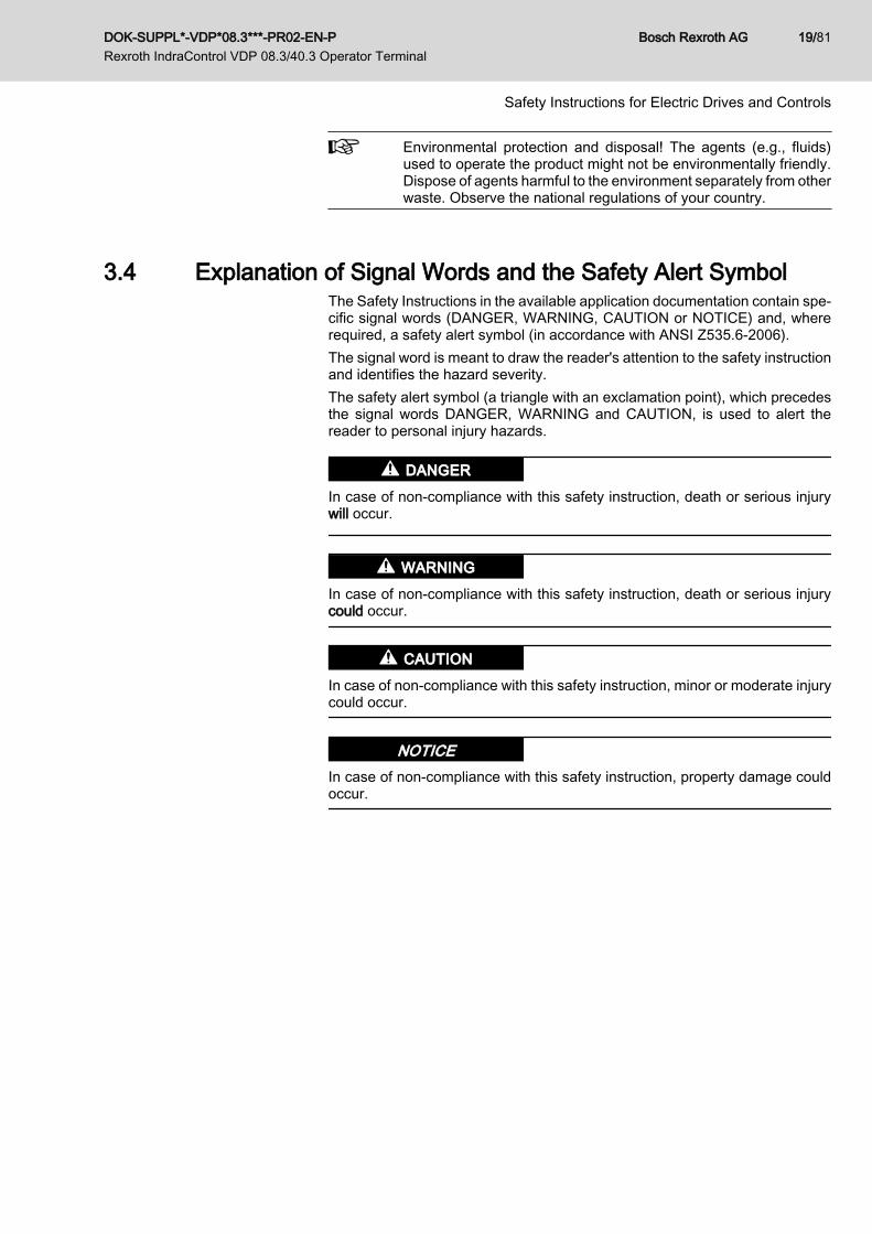
3.4 Explanation of Signal Words and the Safety Alert SymbolThe Safety Instructions in the available application documentation contain spe‐cific signal words (DANGER, WARNING, CAUTION or NOTICE) and, whererequired, a safety alert symbol (in accordance with ANSI Z535.6-2006).The signal word is meant to draw the reader's attention to the safety instructionand identifies the hazard severity.The safety alert symbol (a triangle with an exclamation point), which precedesthe signal words DANGER, WARNING and CAUTION, is used to alert thereader to personal injury hazards.
DANGER
In case of non-compliance with this safety instruction, death or serious injurywill occur.
WARNING
In case of non-compliance with this safety instruction, death or serious injurycould occur.
CAUTION
In case of non-compliance with this safety instruction, minor or moderate injurycould occur.
NOTICEIn case of non-compliance with this safety instruction, property damage couldoccur.
DOK-SUPPL*-VDP*08.3***-PR02-EN-P Rexroth IndraControl VDP 08.3/40.3 Operator Terminal
Bosch Rexroth AG 19/81
Safety Instructions for Electric Drives and Controls

Bosch Rexroth AG DOK-SUPPL*-VDP*08.3***-PR02-EN-P Rexroth IndraControl VDP 08.3/40.3 Operator Terminal
20/81

4 Technical Data4.1 General Information
VDP 08.3
Display 213.36 mm TFT (8.4"), 800 × 600 pixels, 256,000colors
Operation Touch screen operation
Surface − Front panel Color RAL 7035Light gray
Degree of protection, front panel Front panel IP 65 according to DIN EN 60 529Front type 1 according to NEMA (UL)
Degree of protection, total device IP 54
Interface USB connection,Cover degree pf protection IP 65
Weight 3.5 kg
Fig.4-1: Technical data, front of the VDP 08.3
VDP 40.3DI
Display 381 mm TFT (15"), 1024 × 768 pixels, 256,000 col‐ors
Operation Touch screen operation
Surface − Front panel Color RAL 7035Light gray
Degree of protection, front panel Front panel IP 65 according to DIN EN 60 529Front type 1 according to NEMA (UL)
Degree of protection, total device IP 54
Interface USB connection,Cover degree pf protection IP 65
Weight 7.6 kg
Fig.4-2: Technical data, front VDP 40.3
4.2 Voltage SupplyThe VDP operator display is supplied with DC 24 V. The maximum power con‐sumption is 2 A.The power consumption of the VDP 08.3 devices is 20 W, and the power con‐sumption of the VDP 40.3 devices is 35 W.
DOK-SUPPL*-VDP*08.3***-PR02-EN-P Rexroth IndraControl VDP 08.3/40.3 Operator Terminal
Bosch Rexroth AG 21/81
Technical Data
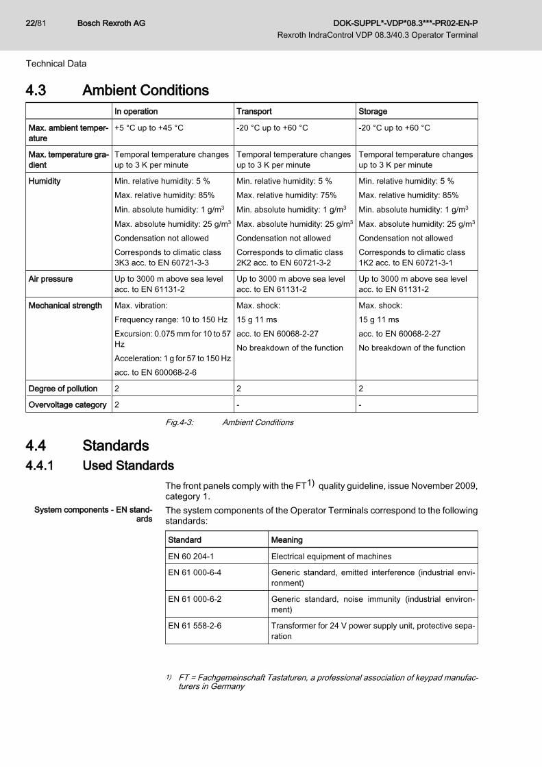
4.3 Ambient Conditions In operation Transport Storage
Max. ambient temper‐ature
+5 °C up to +45 °C -20 °C up to +60 °C -20 °C up to +60 °C
Max. temperature gra‐dient
Temporal temperature changesup to 3 K per minute
Temporal temperature changesup to 3 K per minute
Temporal temperature changesup to 3 K per minute
Humidity Min. relative humidity: 5 %Max. relative humidity: 85%Min. absolute humidity: 1 g/m3
Max. absolute humidity: 25 g/m3
Condensation not allowedCorresponds to climatic class3K3 acc. to EN 60721-3-3
Min. relative humidity: 5 %Max. relative humidity: 75%Min. absolute humidity: 1 g/m3
Max. absolute humidity: 25 g/m3
Condensation not allowedCorresponds to climatic class2K2 acc. to EN 60721-3-2
Min. relative humidity: 5 %Max. relative humidity: 85%Min. absolute humidity: 1 g/m3
Max. absolute humidity: 25 g/m3
Condensation not allowedCorresponds to climatic class1K2 acc. to EN 60721-3-1
Air pressure Up to 3000 m above sea levelacc. to EN 61131-2
Up to 3000 m above sea levelacc. to EN 61131-2
Up to 3000 m above sea levelacc. to EN 61131-2
Mechanical strength Max. vibration:Frequency range: 10 to 150 HzExcursion: 0.075 mm for 10 to 57HzAcceleration: 1 g for 57 to 150 Hzacc. to EN 600068-2-6
Max. shock:15 g 11 msacc. to EN 60068-2-27No breakdown of the function
Max. shock:15 g 11 msacc. to EN 60068-2-27No breakdown of the function
Degree of pollution 2 2 2
Overvoltage category 2 - -
Fig.4-3: Ambient Conditions
4.4 Standards4.4.1 Used Standards
The front panels comply with the FT1) quality guideline, issue November 2009,category 1.
System components - EN stand‐ards
The system components of the Operator Terminals correspond to the followingstandards:
Standard Meaning
EN 60 204-1 Electrical equipment of machines
EN 61 000-6-4 Generic standard, emitted interference (industrial envi‐ronment)
EN 61 000-6-2 Generic standard, noise immunity (industrial environ‐ment)
EN 61 558-2-6 Transformer for 24 V power supply unit, protective sepa‐ration
1) FT = Fachgemeinschaft Tastaturen, a professional association of keypad manufac‐turers in Germany
Bosch Rexroth AG DOK-SUPPL*-VDP*08.3***-PR02-EN-P Rexroth IndraControl VDP 08.3/40.3 Operator Terminal
22/81
Technical Data
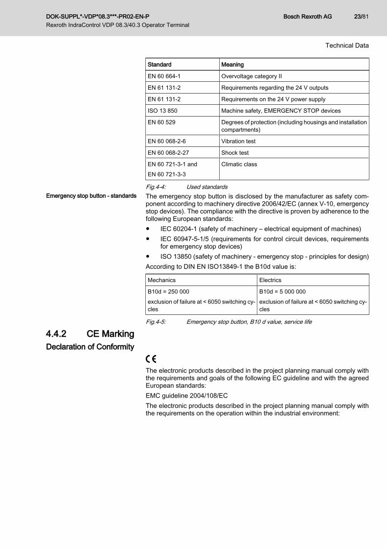
Standard Meaning
EN 60 664-1 Overvoltage category II
EN 61 131-2 Requirements regarding the 24 V outputs
EN 61 131-2 Requirements on the 24 V power supply
ISO 13 850 Machine safety, EMERGENCY STOP devices
EN 60 529 Degrees of protection (including housings and installationcompartments)
EN 60 068-2-6 Vibration test
EN 60 068-2-27 Shock test
EN 60 721-3-1 andEN 60 721-3-3
Climatic class
Fig.4-4: Used standardsEmergency stop button - standards The emergency stop button is disclosed by the manufacturer as safety com‐
ponent according to machinery directive 2006/42/EC (annex V-10, emergencystop devices). The compliance with the directive is proven by adherence to thefollowing European standards:● IEC 60204-1 (safety of machinery – electrical equipment of machines)● IEC 60947-5-1/5 (requirements for control circuit devices, requirements
for emergency stop devices)● ISO 13850 (safety of machinery - emergency stop - principles for design)According to DIN EN ISO13849-1 the B10d value is:
Mechanics Electrics
B10d = 250 000exclusion of failure at < 6050 switching cy‐cles
B10d = 5 000 000exclusion of failure at < 6050 switching cy‐cles
Fig.4-5: Emergency stop button, B10 d value, service life
4.4.2 CE MarkingDeclaration of Conformity
The electronic products described in the project planning manual comply withthe requirements and goals of the following EC guideline and with the agreedEuropean standards:EMC guideline 2004/108/ECThe electronic products described in the project planning manual comply withthe requirements on the operation within the industrial environment:
DOK-SUPPL*-VDP*08.3***-PR02-EN-P Rexroth IndraControl VDP 08.3/40.3 Operator Terminal
Bosch Rexroth AG 23/81
Technical Data
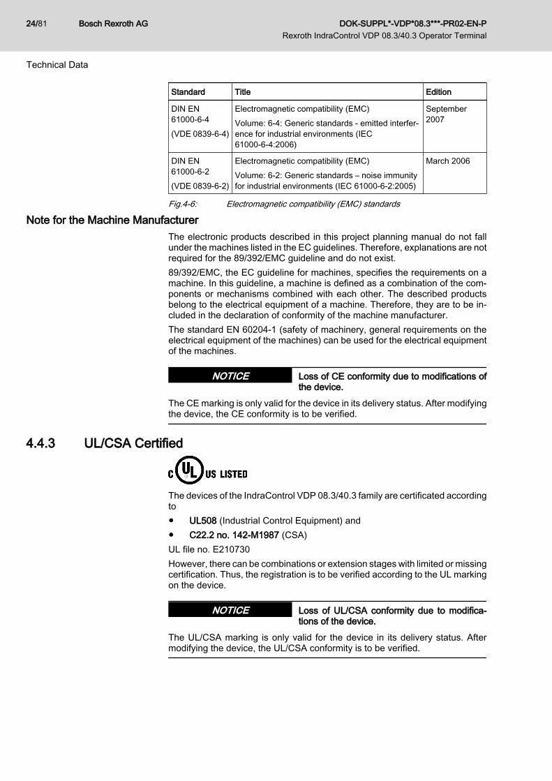
Standard Title Edition
DIN EN61000-6-4(VDE 0839-6-4)
Electromagnetic compatibility (EMC)Volume: 6-4: Generic standards - emitted interfer‐ence for industrial environments (IEC61000-6-4:2006)
September2007
DIN EN61000-6-2(VDE 0839-6-2)
Electromagnetic compatibility (EMC)Volume: 6-2: Generic standards – noise immunityfor industrial environments (IEC 61000-6-2:2005)
March 2006
Fig.4-6: Electromagnetic compatibility (EMC) standards
Note for the Machine ManufacturerThe electronic products described in this project planning manual do not fallunder the machines listed in the EC guidelines. Therefore, explanations are notrequired for the 89/392/EMC guideline and do not exist.89/392/EMC, the EC guideline for machines, specifies the requirements on amachine. In this guideline, a machine is defined as a combination of the com‐ponents or mechanisms combined with each other. The described productsbelong to the electrical equipment of a machine. Therefore, they are to be in‐cluded in the declaration of conformity of the machine manufacturer.The standard EN 60204-1 (safety of machinery, general requirements on theelectrical equipment of the machines) can be used for the electrical equipmentof the machines.
Loss of CE conformity due to modifications ofthe device.
NOTICE
The CE marking is only valid for the device in its delivery status. After modifyingthe device, the CE conformity is to be verified.
4.4.3 UL/CSA Certified
The devices of the IndraControl VDP 08.3/40.3 family are certificated accordingto● UL508 (Industrial Control Equipment) and● C22.2 no. 142-M1987 (CSA)UL file no. E210730However, there can be combinations or extension stages with limited or missingcertification. Thus, the registration is to be verified according to the UL markingon the device.
Loss of UL/CSA conformity due to modifica‐tions of the device.
NOTICE
The UL/CSA marking is only valid for the device in its delivery status. Aftermodifying the device, the UL/CSA conformity is to be verified.
Bosch Rexroth AG DOK-SUPPL*-VDP*08.3***-PR02-EN-P Rexroth IndraControl VDP 08.3/40.3 Operator Terminal
24/81
Technical Data

4.5 Wear PartsThe wear parts as well as their service life are described in this section. Wearparts are not subject to any warranty.
Backlight The service life of the backlight is limited. After this time has been exceeded,the backlight will produce only 50 % of its original brightness. This time is 50,000hours if the surrounding air temperature is 25 °C.The backlight can be exchanged only be the Bosch Rexroth Service, see chap‐ter 13 "Service and Support" on page 77.
4.6 Compatibility TestAll Rexroth controls and drives are developed and tested according to the lateststate-of-the-art of technology.As it is impossible to follow the continuing development of all materials (e. g.lubricants in machine tools) which may interact with our controls and drives, itcannot be completely ruled out that any reactions with the materials used byBosch Rexroth might occur.For this reason, before using the respective material a compatibility test has tobe carried out for new lubricants, cleaning agents etc. and our housings / ourhousing materials.
DOK-SUPPL*-VDP*08.3***-PR02-EN-P Rexroth IndraControl VDP 08.3/40.3 Operator Terminal
Bosch Rexroth AG 25/81
Technical Data

Bosch Rexroth AG DOK-SUPPL*-VDP*08.3***-PR02-EN-P Rexroth IndraControl VDP 08.3/40.3 Operator Terminal
26/81

5 Dimensions, Installation and Wiring5.1 Housing Dimensions5.1.1 General Information
All values in the illustrations are given in mm.
5.1.2 Housing Dimensions VDP 08.3Housing dimensions VDP 08.3
Fig.5-1: Dimensions, front panel of the VDP 08.3 devices
DOK-SUPPL*-VDP*08.3***-PR02-EN-P Rexroth IndraControl VDP 08.3/40.3 Operator Terminal
Bosch Rexroth AG 27/81
Dimensions, Installation and Wiring

Fig.5-2: VDP 08.3, top view
Fig.5-3: VDP 08.3, left view
Bosch Rexroth AG DOK-SUPPL*-VDP*08.3***-PR02-EN-P Rexroth IndraControl VDP 08.3/40.3 Operator Terminal
28/81
Dimensions, Installation and Wiring

Fig.5-4: VDP 08.3, rear view
DOK-SUPPL*-VDP*08.3***-PR02-EN-P Rexroth IndraControl VDP 08.3/40.3 Operator Terminal
Bosch Rexroth AG 29/81
Dimensions, Installation and Wiring

5.1.3 Housing Dimensions VDP 40.3Housing dimensions VDP 40.3
Fig.5-5: Dimensions, front panel of the VDP 40.3DI devices
Fig.5-6: VDP 40.3 DI, top view
Bosch Rexroth AG DOK-SUPPL*-VDP*08.3***-PR02-EN-P Rexroth IndraControl VDP 08.3/40.3 Operator Terminal
30/81
Dimensions, Installation and Wiring
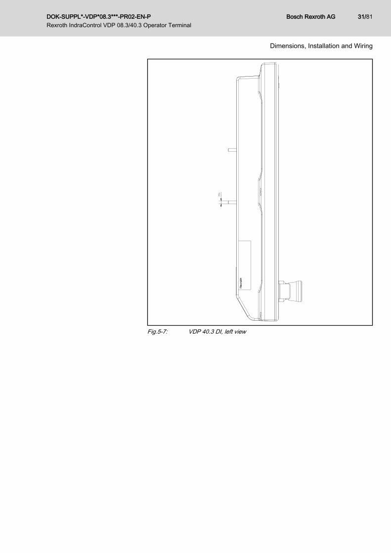
Fig.5-7: VDP 40.3 DI, left view
DOK-SUPPL*-VDP*08.3***-PR02-EN-P Rexroth IndraControl VDP 08.3/40.3 Operator Terminal
Bosch Rexroth AG 31/81
Dimensions, Installation and Wiring
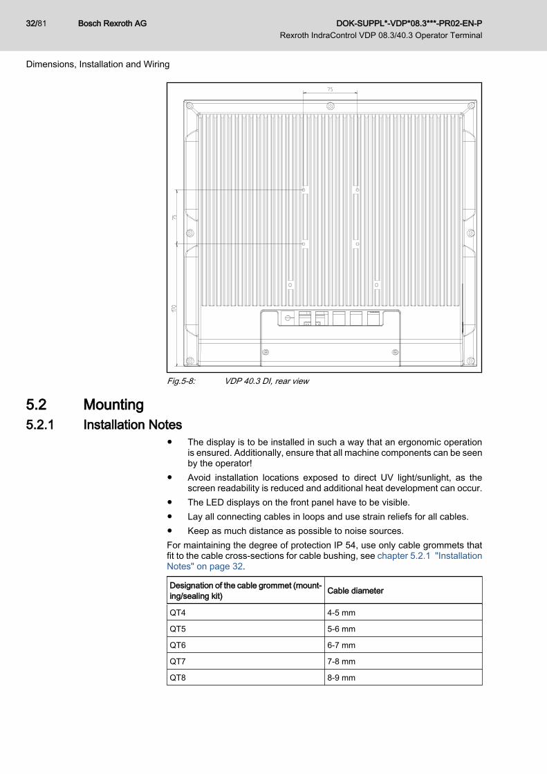
Fig.5-8: VDP 40.3 DI, rear view
5.2 Mounting5.2.1 Installation Notes
● The display is to be installed in such a way that an ergonomic operationis ensured. Additionally, ensure that all machine components can be seenby the operator!
● Avoid installation locations exposed to direct UV light/sunlight, as thescreen readability is reduced and additional heat development can occur.
● The LED displays on the front panel have to be visible.● Lay all connecting cables in loops and use strain reliefs for all cables.● Keep as much distance as possible to noise sources.For maintaining the degree of protection IP 54, use only cable grommets thatfit to the cable cross-sections for cable bushing, see chapter 5.2.1 "InstallationNotes" on page 32.
Designation of the cable grommet (mount‐ing/sealing kit) Cable diameter
QT4 4-5 mm
QT5 5-6 mm
QT6 6-7 mm
QT7 7-8 mm
QT8 8-9 mm
Bosch Rexroth AG DOK-SUPPL*-VDP*08.3***-PR02-EN-P Rexroth IndraControl VDP 08.3/40.3 Operator Terminal
32/81
Dimensions, Installation and Wiring
Designation of the cable grommet (mount‐ing/sealing kit) Cable diameter
QT11 11-12 mm
QT12 12-13 mm
QTB Blind grommet
Fig.5-9: Cable diameter and corresponding cable grommet
The cables, which are lead through a cable grommet, are to be provided witha strain relief. This can be realized e.g. with a cable wrap behind the grommet.
5.2.2 Mounting
Loss of IP degree of protection due to wrongsize and/or wrong mounting of the cable grom‐met and damaged and/or wrongly mounted ornot sufficiently fastened covers.
NOTICE
A cable grommet fitting to the cable diameter is to be used and to be mountedproperly. The sealing of the cover must not be damaged. The cover is to bemounted properly and is to be fastened with the correct mounting torque, seealso fig. 5-15 "Mounting torques" on page 35.
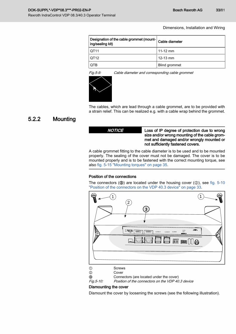
Position of the connectionsThe connectors (③) are located under the housing cover (②), see fig. 5-10"Position of the connectors on the VDP 40.3 device" on page 33.
211
OnOff
S1XVID XSER XUSB1/2 XUSB3/4 XUSBIN
X1S124V
3
1 2
① Screws② Cover③ Connectors (are located under the cover)Fig.5-10: Position of the connectors on the VDP 40.3 deviceDismounting the coverDismount the cover by loosening the screws (see the following illustration).
DOK-SUPPL*-VDP*08.3***-PR02-EN-P Rexroth IndraControl VDP 08.3/40.3 Operator Terminal
Bosch Rexroth AG 33/81
Dimensions, Installation and Wiring

x
Openings for cable grommets
Fig.5-11: Dismounting the coverUsing the cable grommet● Select the corresponding cable grommet from the table, see fig. 5-9 "Cable
diameter and corresponding cable grommet" on page 32.● The cable grommets and the connector for connecting the keypad are in
the delivered accessories kit.● Lay the cable grommet around the cable, see fig. 5-12 "Laying the cable
grommet around the cable" on page 34.
cable
Select cable grommetaccording to the table
Fig.5-12: Laying the cable grommet around the cable
● Plug the cable grommet into the housing, see fig. 5-13 "Plugging the cablegrommet into the housing" on page 34.
housing
cable grommet
flat surface
Fig.5-13: Plugging the cable grommet into the housing● The cables, which are lead through a cable grommet, are to be provided
with a strain relief, see fig. 5-14 "Strain relief realized by a cable wrap" onpage 35.
Bosch Rexroth AG DOK-SUPPL*-VDP*08.3***-PR02-EN-P Rexroth IndraControl VDP 08.3/40.3 Operator Terminal
34/81
Dimensions, Installation and Wiring
cable grommet
cable wrapcable
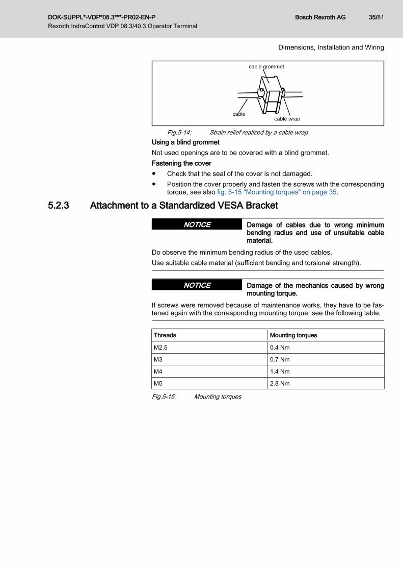
Fig.5-14: Strain relief realized by a cable wrapUsing a blind grommetNot used openings are to be covered with a blind grommet.Fastening the cover● Check that the seal of the cover is not damaged.● Position the cover properly and fasten the screws with the corresponding
torque, see also fig. 5-15 "Mounting torques" on page 35.
5.2.3 Attachment to a Standardized VESA Bracket
Damage of cables due to wrong minimumbending radius and use of unsuitable cablematerial.
NOTICE
Do observe the minimum bending radius of the used cables.Use suitable cable material (sufficient bending and torsional strength).
Damage of the mechanics caused by wrongmounting torque.
NOTICE
If screws were removed because of maintenance works, they have to be fas‐tened again with the corresponding mounting torque, see the following table.
Threads Mounting torques
M2.5 0.4 Nm
M3 0.7 Nm
M4 1.4 Nm
M5 2.8 Nm
Fig.5-15: Mounting torques
DOK-SUPPL*-VDP*08.3***-PR02-EN-P Rexroth IndraControl VDP 08.3/40.3 Operator Terminal
Bosch Rexroth AG 35/81
Dimensions, Installation and Wiring

1
2
① VESA attachment with four M4 threaded bolts (75 mm × 75 mm)② Cable bushings, appropriate for ready-made cablesFig.5-16: Position of VESA fastening screws and cable bushings
5.2.4 VESA BracketThe operator terminals can be attached to a standardized VESA bracket, whichis offered by different manufacturers.
Fig.5-17: VESA bracket
Bosch Rexroth AG DOK-SUPPL*-VDP*08.3***-PR02-EN-P Rexroth IndraControl VDP 08.3/40.3 Operator Terminal
36/81
Dimensions, Installation and Wiring

5.3 Electrical WiringWiring 230 V
PE
PE PE
PEPE
PE
PE(1)
6 mm² (green/yellow)16 mm² (green/yellow)
min. 16 mm² (green/yellow)
all housing parts (functional earth)to the deviceto the housing of the control cabinet
PE neutral point
230V
400V 4 mm² (green/yellow)
16 mm² (green/yellow)
4 mm² (green/yellow
Fuses, better: protective motor switches
category III
category II
Transformer
Terminals in e.g. drives
W1 NV1
U1
L1 L2 L3 N
leads
L1.1
L2.1
L3.1
N PE
PE N U2
PE N1
U2
4 mm² (green/yellow)
24 VDC
Length max. 4 m
Power unitVAP01.1H-W23024-010-NN
+24 V
0 V
24 VDC
Overvoltage
Overvoltage
acc. to EN60742
isolated arrangement
N-conductor:Use only with permission ofthe operator!
230 V power supplyoperator terminalsservice plug receptacle(s)
category IOvervoltage
PE bars are to be installed preferably on the mounting plate.In case of isolated PE bars, both ends must be connected to the mounting plateby means of copper strips with a maximum length of 20 cm.The cross-section of the copper strips has to be at least equal to that of the incoming mains cable.
(1)
Fig.5-18: Wiring 230 V
High electrical voltage! Danger to life and riskof injury caused by electric shock or bodilyharm caused by net voltage on the protectiveextra-low voltage (e.g. +24V)! Connection ofpower supply units, which cause protective ex‐tra-low voltage, to net voltages, for which theyare not designed.
DANGER
Power supply units, whose net connection is designed for overvoltage categoryII, are to be connected to a net voltage with overvoltage category II, see "Wiring230 V" on page 37.
DOK-SUPPL*-VDP*08.3***-PR02-EN-P Rexroth IndraControl VDP 08.3/40.3 Operator Terminal
Bosch Rexroth AG 37/81
Dimensions, Installation and Wiring
Wiring 400 V
PE
PE PE
PEPE
PE
PE(1)
6 mm² (green/yellow)16 mm² (green/yellow)
min. 16 mm² (green/yellow)
all housing parts (functional earth)to the deviceto the housing of the control cabinet
L1.1
L2.1
L3.1
PE
PE neutral point
230V
400V 4 mm² (green/yellow)
16 mm² (green/yellow)
4 mm² (green/yellow)
Fuses, better: protective motor switchesOvervoltage
Transformer
Terminals in isolated arrangement
e.g.drives
W1 NV1
U1
L1 L2 L3 N
leads
L1.1
L2.1
L3.1
N PE
PE N U2
PE N1
U2
4 mm² (green/yellow)
230 V supply
= 24 VDC
Power unit
+24 V
24 VDC
category III
acc. to EN 60742
Overvoltagecategory II
Overvoltagecategory I
operator terminalsservice plug receptacle(s)
N conductor:Use only withpermission of the operator!
0 V
PE bars are to be installed preferably on the mounting plate.In case of isolated PE bars, both ends must be connected to the mounting plateby means of copper strips with a maximum length of 20 cm.The cross-section of the copper strips has to be at least equal to that of the incoming mains cable.
(1)
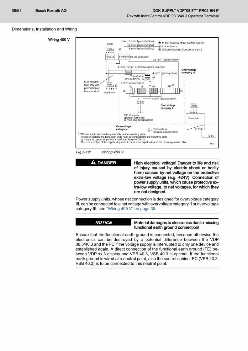
Fig.5-19: Wiring 400 V
High electrical voltage! Danger to life and riskof injury caused by electric shock or bodilyharm caused by net voltage on the protectiveextra-low voltage (e.g. +24V)! Connection ofpower supply units, which cause protective ex‐tra-low voltage, to net voltages, for which theyare not designed.
DANGER
Power supply units, whose net connection is designed for overvoltage categoryIII, can be connected to a net voltage with overvoltage category II or overvoltagecategory III, see "Wiring 400 V" on page 38.
Material damages to electronics due to missingfunctional earth ground connection!
NOTICE
Ensure that the functional earth ground is connected, because otherwise theelectronics can be destroyed by a potential difference between the VDP08.3/40.3 and the PC if the voltage supply is interrupted to only one device andestablished again. A direct connection of the functional earth ground (FE) be‐tween VDP xx.3 display and VPB 40.3, VSB 40.3 is optimal. If the functionalearth ground is wired at a neutral point, also the control cabinet PC (VPB 40.3,VSB 40.3) is to be connected to this neutral point.
Bosch Rexroth AG DOK-SUPPL*-VDP*08.3***-PR02-EN-P Rexroth IndraControl VDP 08.3/40.3 Operator Terminal
38/81
Dimensions, Installation and Wiring
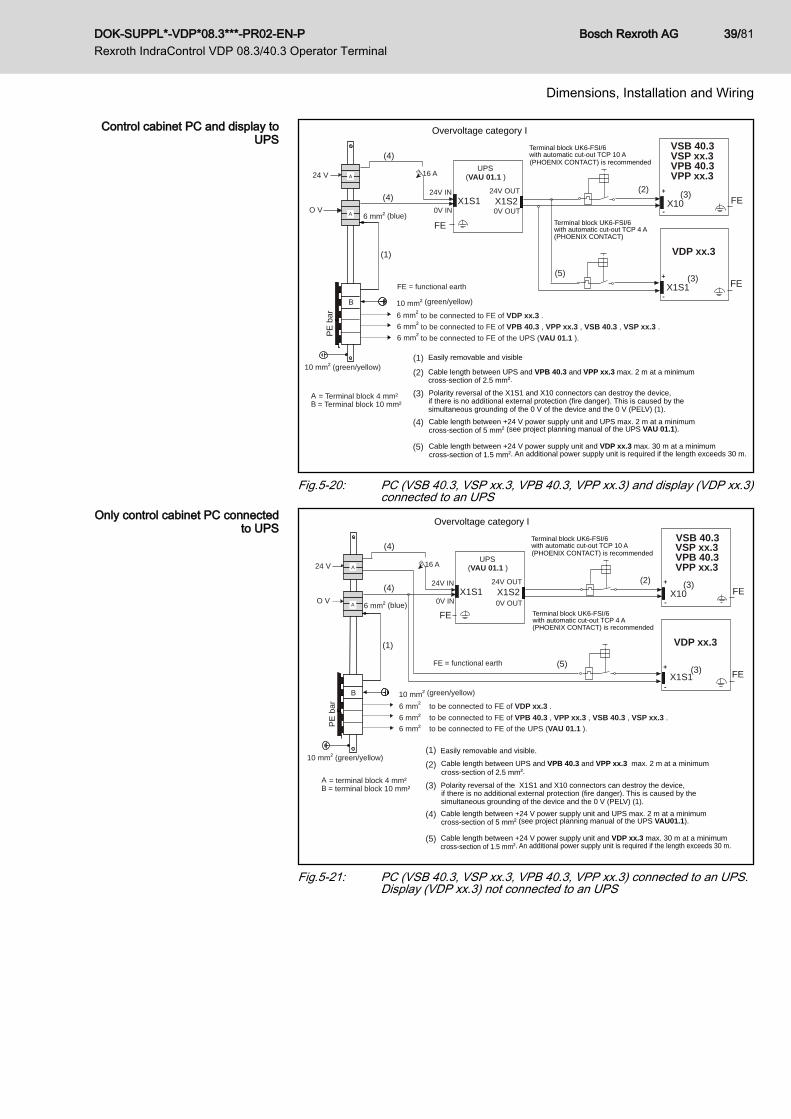
Control cabinet PC and display toUPS
10 mm² (green/yellow)
6 mm² (blue)
PE
bar
A
B
A
Overvoltage category I
(4)
to be connected to FE of VDP xx.3 .to be connected to FE of VPB 40.3 , VPP xx.3 , VSB 40.3 , VSP xx.3 .to be connected to FE of the UPS (VAU 01.1 ).
X1S2
UPS
FE = functional earth
(VAU 01.1 )
0V OUT
24V OUTX1S1
0V IN
24V IN
VDP xx.3
X1S1+
-
FE
X10
VPB 40.3
+
-FE
(2)
+24V
O V
10 mm² (green/yellow)
A = Terminal block 4 mm²B = Terminal block 10 mm²
(1)(2)
(3)
(4)
(5)
(1)
(4) (3)
(3)(5)
16 A24 V VPP xx.3
Terminal block UK6-FSI/6with automatic cut-out TCP 10 A(PHOENIX CONTACT) is recommended
Terminal block UK6-FSI/6with automatic cut-out TCP 4 A(PHOENIX CONTACT)
Easily removable and visible
FE
Cable length between UPS and VPB 40.3 and VPP xx.3 max. 2 m at a minimumcross-section of 2.5 mm².
Polarity reversal of the X1S1 and X10 connectors can destroy the device,if there is no additional external protection (fire danger). This is caused by the
Cable length between +24 V power supply unit and UPS max. 2 m at a minimum cross-section of 5 mm² (see project planning manual of the UPS VAU 01.1).
Cable length between +24 V power supply unit and VDP xx.3 max. 30 m at a minimumcross-section of 1.5 mm². An additional power supply unit is required if the length exceeds 30 m.
VSP xx.3VSB 40.3
simultaneous grounding of the 0 V of the device and the 0 V (PELV) (1).
6 mm²
6 mm²
6 mm²
Fig.5-20: PC (VSB 40.3, VSP xx.3, VPB 40.3, VPP xx.3) and display (VDP xx.3)connected to an UPS
Only control cabinet PC connectedto UPS
10 mm² (green/yellow)
6 mm² (blue)
PE
bar
A
B
A
Overvoltage category I
(4)
6 mm² a to be connected to FE of VDP xx.3 .
6 mm² a to be connected to FE of the UPS (VAU 01.1 ).
X1S2
UPS(VAU 01.1 )
0V OUT
24V OUTX1S1
0V IN
24V IN
VDP xx.3
X1S1+
-
FE
+
-FE
(2)
+24V
O V
10 mm² (green/yellow)
A = terminal block 4 mm²B = terminal block 10 mm²
(1)
(4)
(3)(5)
16 A24 V
Terminal block UK6-FSI/6with automatic cut-out TCP 10 A(PHOENIX CONTACT) is recommended
Terminal block UK6-FSI/6with automatic cut-out TCP 4 A(PHOENIX CONTACT) is recommended
FE
VPB 40.3VPP xx.3
VSP xx.3VSB 40.3
X10(3)
6 mm² a to be connected to FE of VPB 40.3 , VPP xx.3 , VSB 40.3 , VSP xx.3 .
FE = functional earth
(1)(2)
(3)
(4)
(5)
Easily removable and visible.
cross-section of 2.5 mm².
Cable length between +24 V power supply unit and UPS max. 2 m at a minimum cross-section of 5 mm² (see project planning manual of the UPS VAU01.1).
Cable length between +24 V power supply unit and VDP xx.3 max. 30 m at a minimumcross-section of 1.5 mm². An additional power supply unit is required if the length exceeds 30 m.
Polarity reversal of the X1S1 and X10 connectors can destroy the device, if there is no additional external protection (fire danger). This is caused by the simultaneous grounding of the device and the 0 V (PELV) (1).
Cable length between UPS and VPB 40.3 and VPP xx.3 max. 2 m at a minimum
Fig.5-21: PC (VSB 40.3, VSP xx.3, VPB 40.3, VPP xx.3) connected to an UPS.Display (VDP xx.3) not connected to an UPS
DOK-SUPPL*-VDP*08.3***-PR02-EN-P Rexroth IndraControl VDP 08.3/40.3 Operator Terminal
Bosch Rexroth AG 39/81
Dimensions, Installation and Wiring

Bosch Rexroth AG DOK-SUPPL*-VDP*08.3***-PR02-EN-P Rexroth IndraControl VDP 08.3/40.3 Operator Terminal
40/81

6 Display and Operating Components6.1 Backlight Switch-off6.1.1 General Information
The service life of the backlight of the display is limited (see chapter 4.5 "WearParts" on page 25).To extend the service life of the LCD backlight, the flat screen display is provi‐ded with a backlight switch-off. This function "darkens" the display when nooperation of the panel PC occurred for a certain period of time. The length ofthe time interval can be specified in the Windows Control Panel under "PowerOptions" (see fig. 6-1 "Setting the darkening mode of the display in the WindowsControl Panel" on page 41).
Fig.6-1: Setting the darkening mode of the display in the Windows Control Panel
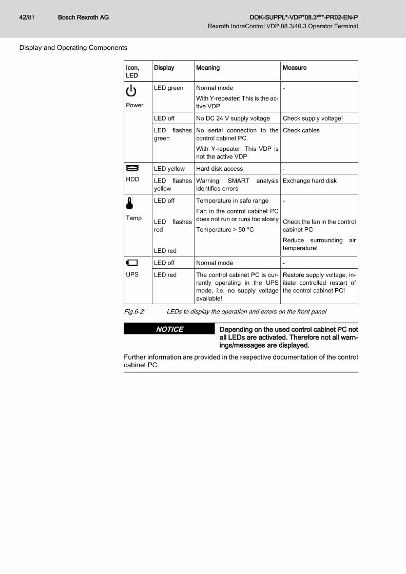
6.2 Operating and Error Displays4 LEDs are provided in the upper part of the front panel to display the devicestatuses and errors of the connected control cabinet PC. Start the measuresspecified in the following table if one of the succeeding LEDs displays an erroror a note.
DOK-SUPPL*-VDP*08.3***-PR02-EN-P Rexroth IndraControl VDP 08.3/40.3 Operator Terminal
Bosch Rexroth AG 41/81
Display and Operating Components
Icon,LED
Display Meaning Measure
Power
LED green Normal modeWith Y-repeater: This is the ac‐tive VDP
-
LED off No DC 24 V supply voltage Check supply voltage!
LED flashesgreen
No serial connection to thecontrol cabinet PC.With Y-repeater: This VDP isnot the active VDP
Check cables
HDDLED yellow Hard disk access -
LED flashesyellow
Warning: SMART analysisidentifies errors
Exchange hard disk
Temp
LED off LED flashesred LED red
Temperature in safe rangeFan in the control cabinet PCdoes not run or runs too slowlyTemperature > 50 °C
- Check the fan in the controlcabinet PCReduce surrounding airtemperature!
UPS
LED off Normal mode -
LED red The control cabinet PC is cur‐rently operating in the UPSmode, i.e. no supply voltageavailable!
Restore supply voltage, in‐itiate controlled restart ofthe control cabinet PC!
Fig.6-2: LEDs to display the operation and errors on the front panel
Depending on the used control cabinet PC notall LEDs are activated. Therefore not all warn‐ings/messages are displayed.
NOTICE
Further information are provided in the respective documentation of the controlcabinet PC.
Bosch Rexroth AG DOK-SUPPL*-VDP*08.3***-PR02-EN-P Rexroth IndraControl VDP 08.3/40.3 Operator Terminal
42/81
Display and Operating Components

6.3 Operation6.3.1 Key Positions
Fig.6-3: Position of the keys on the VDP 08.3 and VDP 40.3The keys are located below the screen.
6.4 Touch ScreenThe application software is operated via the touch-sensitive interface of thedisplay.Start the calibration via the preinstalled "IPCMnt.exe" maintenance program.The program is to be found under Start ▶ ProgramFiles ▶ Bosch Rexroth.The icons available on the touch screen depend on the used application soft‐ware.
Danger of touch screen desctruction causedby operating the touch screen with inappropri‐ate objects (e.g. with a screwdriver)!
NOTICE
Operate the touch screen only with a touch pen or your finger.
DOK-SUPPL*-VDP*08.3***-PR02-EN-P Rexroth IndraControl VDP 08.3/40.3 Operator Terminal
Bosch Rexroth AG 43/81
Display and Operating Components

Bosch Rexroth AG DOK-SUPPL*-VDP*08.3***-PR02-EN-P Rexroth IndraControl VDP 08.3/40.3 Operator Terminal
44/81
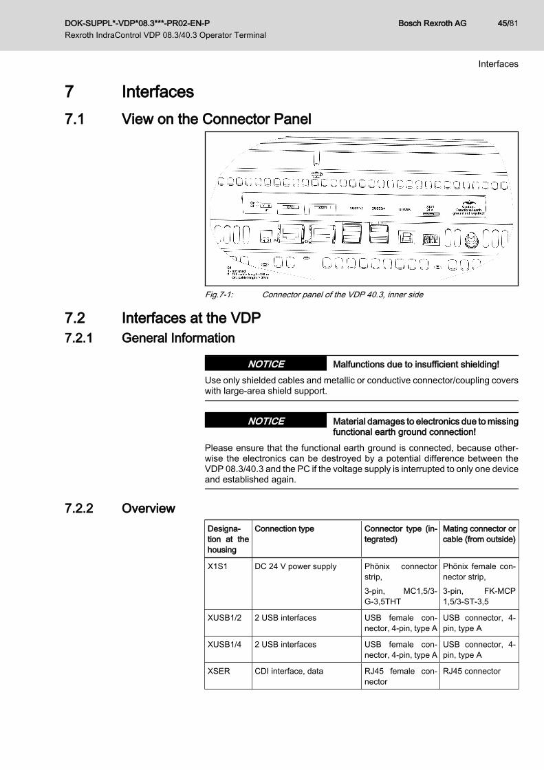
7 Interfaces7.1 View on the Connector Panel
Fig.7-1: Connector panel of the VDP 40.3, inner side
7.2 Interfaces at the VDP7.2.1 General Information
Malfunctions due to insufficient shielding!NOTICEUse only shielded cables and metallic or conductive connector/coupling coverswith large-area shield support.
Material damages to electronics due to missingfunctional earth ground connection!
NOTICE
Please ensure that the functional earth ground is connected, because other‐wise the electronics can be destroyed by a potential difference between theVDP 08.3/40.3 and the PC if the voltage supply is interrupted to only one deviceand established again.
7.2.2 OverviewDesigna‐tion at thehousing
Connection type Connector type (in‐tegrated)
Mating connector orcable (from outside)
X1S1 DC 24 V power supply Phönix connectorstrip,3-pin, MC1,5/3-G-3,5THT
Phönix female con‐nector strip,3-pin, FK-MCP1,5/3-ST-3,5
XUSB1/2 2 USB interfaces USB female con‐nector, 4-pin, type A
USB connector, 4-pin, type A
XUSB1/4 2 USB interfaces USB female con‐nector, 4-pin, type A
USB connector, 4-pin, type A
XSER CDI interface, data RJ45 female con‐nector
RJ45 connector
DOK-SUPPL*-VDP*08.3***-PR02-EN-P Rexroth IndraControl VDP 08.3/40.3 Operator Terminal
Bosch Rexroth AG 45/81
Interfaces

Designa‐tion at thehousing
Connection type Connector type (in‐tegrated)
Mating connector orcable (from outside)
XVID CDI interface, screen RJ45 female con‐nector
RJ45 connector
XUSBIN USB2.0 connection to thecontrol cabinet PC. Length 5m max.Only high-speed USB2.0 ca‐bles are to be used (seechapter 12 "Ordering Infor‐mation" on page 71)
USB female con‐nector, 4-pin, type B
USB connector, 4-pin, type B
X2 Connection keypad Phönix male con‐nector strip, 6-pin,MCV 1.5/6- G-3.5
Phönix female con‐nector strip, 6-pin,FK-MCP 1.5/6-ST-3.5
X3 Connection keypad Phönix male con‐nector strip, 10-pin,MCV 1.5/10-G-3.5
Phönix female con‐nector strip, 10-pin,FK-MCP 1.5/10-ST-3.5
Fig.7-2: Interfaces on the VDP 08.3 and VDP 40.3
7.2.3 S1 DIP SwitchOverview
Designation at thehousing
Switch type Function
S1/switch 1 DIP switch Without function
S1/switch 2 DIP switch OFF: Cable length to the control cabinet PC <30 mON: Cable length to the control cabinet PC >30 m
Fig.7-3: DIP switch on the VDP
Operation ModesCable length between control cabi‐net PC and VDP is 5 m maximum
If the cable length to the control cabinet PC does not exceed 5 m, the USBconnection to the VDP can be executed in the USB 2.0 mode (High Speed,max. 480 Mb/s) by using an additional USB 2.0 cable. The S1 switch 2 mustbe in the "OFF" position. If the cable is not plugged, the USB connection isexecuted in USB-1.1 (max. data rate at Full Speed: 12 Mb/s).
Cable length between control cabi‐net PC and VDP max. 30 m (stand‐
ard USB mode)
The USB connection is executed in the USB1.1 mode. The S1 switch 2 mustbe in the "OFF" position.
Malfunctions in the standard USB modecaused by strokes!
NOTICE
No internal strokes are to be integrated into the connected USB device (be‐cause of the additional runtime) so that the standard USB mode works with acable length of up to 30 m!
Bosch Rexroth AG DOK-SUPPL*-VDP*08.3***-PR02-EN-P Rexroth IndraControl VDP 08.3/40.3 Operator Terminal
46/81
Interfaces

Cable length between control cabi‐net PC and VDP greater than 30 m
(extended USB mode)
The USB connection is performed in the limited full speed mode. Only key‐boards and mice can be connected to the VDP. No internal HUBs are to beintegrated into these USB devices. Other USB devices, such as memory sticks,are not supported. The S1 switch 2 must be in the "ON" position.For information about the cable lengths related to the display resolution, seechapter 10.4.4 "Cable connections and cable types allowed" on page 63.
7.2.4 DC 24 V Voltage Supply
Fig.7-4: Interface to the control cabinet PC
Pin Function
1 Supply voltage +24 V
2 Supply voltage 0 V
3 n. c.
A standard 24 V industrial power supply unit can be used for the voltage supply.
If the distance between VDP and control cabi‐net PC exceeds 50 m, equalizing currents mayflow when using a non-isolated power supplyunit because pin 2 is internally connected tothe housing.
NOTICE
In this case an isolated power supply unit is to be used.
There are two possibilities to connect the external VDP 08.3/40.3 operator dis‐play to the 24 V voltage supply:● Connection to the 24 V Out of the external UPS (if available).
For this variant, the display and the control cabinet PC are switched off atthe same time by the UPS. The user can carry out actions manually whenthere is a power failure of 24 V or if the control cabinet PC is switched offwhile the PC is shut down.
● Direct connection to the 24 V supply voltage.If there is no supply voltage of 24 V, the operator display immediatelydarkens. The user cannot execute any actions via the operator displayduring the shutdown of the control cabinet PC.
DOK-SUPPL*-VDP*08.3***-PR02-EN-P Rexroth IndraControl VDP 08.3/40.3 Operator Terminal
Bosch Rexroth AG 47/81
Interfaces

X10
control cabinet PCUPS230 V → 24 V
24 V
24 V
24 V230 V ~ +
+
U
+
+
12
3
USB connectiontype B
USB connection
USB cable
X1S1/2 (0 V)X1S1/1 (24 VDC)
XSER
XVID
XSER
XVID
operator display
XUSBINXUSB1..6
XUSB1...4
Front USB connection
for USB2.0
External Out
In
type A
–
–
–
–
1
VDP xx.3
(as option)
power supply unit
① See chapter "Operation Modes" on page 46 section "Distance betweencontrol cabinet PC and VDP max. 5 m".
Fig.7-5: Voltage supply and optional USB2.0 port
7.2.5 XUSB InterfacesThe devices are provided with four USB interfaces on the connector panel(XUSB1/2 and XUSB3/4) and - depending on the variant - one USB interfaceon the front panel.
Switching off of the VDP power supply unit ifthe total current of all USB female connectorsexceeds 1 A.
NOTICE
The maximum power consumption of one USB connector must not exceed 500mA. The total current of all USB female connectors must not exceed 1 A.
Fig.7-6: USB interfaces XUSB1/2 and XUSB3/4Operating the USB connections on
the VDP 16.3/40.3 in the USB2.0mode
The USB connections on the VDP 08.3/40.3 only support USB1.1 because thedata is transferred to the control cabinet PC by using the XSER interface. TheXUSB1 to XUSB6 connection on the control cabinet PC support USB2.0. IfUSB2.0 is also required on the VDP 08.3/40.3, it can be implemented by con‐necting the XUSBIN connection to the VDP 08.3/40.3 to one USB connection(XUSB1 up to XUSB6) of the control cabinet PC by using an USB cable (seefig. 7-5 "Voltage supply and optional USB2.0 port" on page 48). The USB cablecan be ordered as accessory, see chapter 12.2.5 "Connecting Cable for USBInterface" on page 74.
Bosch Rexroth AG DOK-SUPPL*-VDP*08.3***-PR02-EN-P Rexroth IndraControl VDP 08.3/40.3 Operator Terminal
48/81
Interfaces
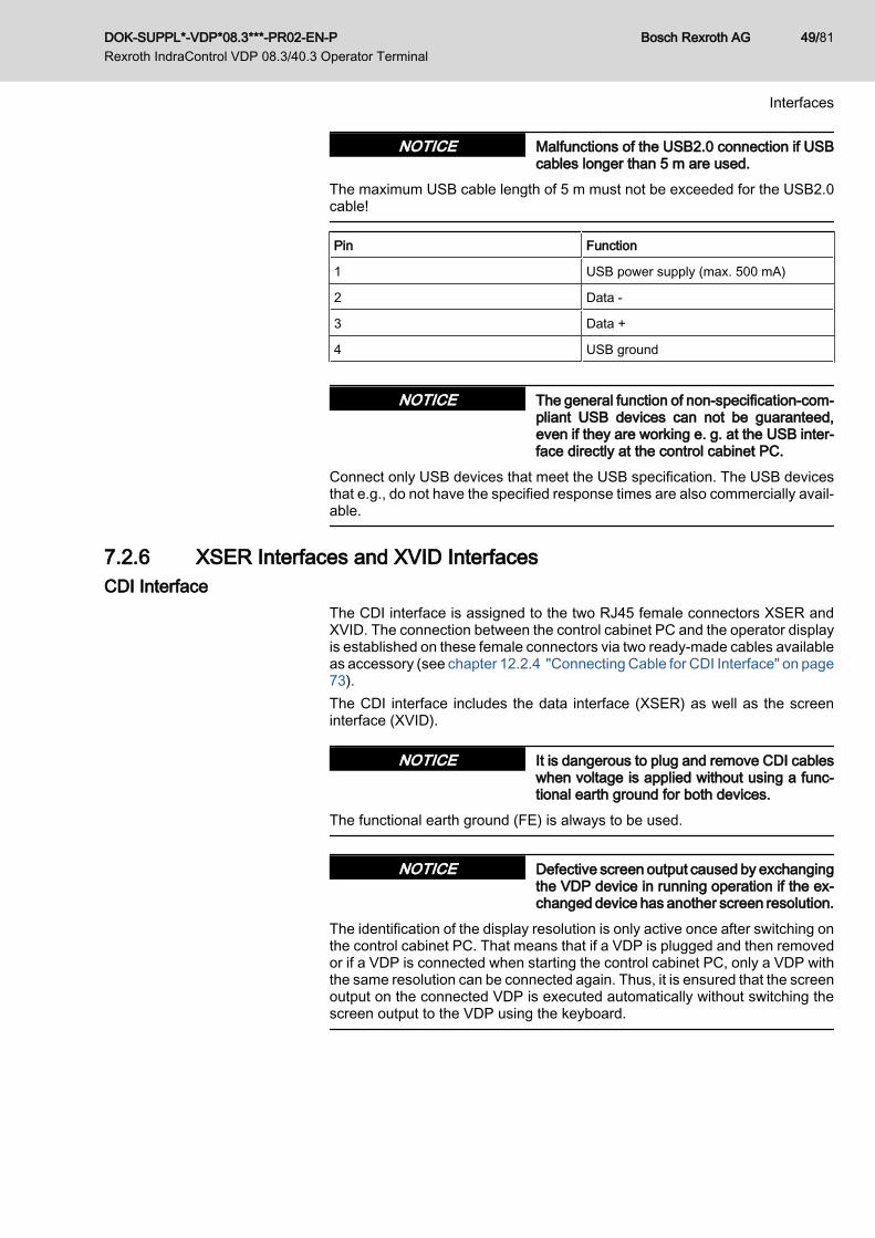
Malfunctions of the USB2.0 connection if USBcables longer than 5 m are used.
NOTICE
The maximum USB cable length of 5 m must not be exceeded for the USB2.0cable!
Pin Function
1 USB power supply (max. 500 mA)
2 Data -
3 Data +
4 USB ground
The general function of non-specification-com‐pliant USB devices can not be guaranteed,even if they are working e. g. at the USB inter‐face directly at the control cabinet PC.
NOTICE
Connect only USB devices that meet the USB specification. The USB devicesthat e.g., do not have the specified response times are also commercially avail‐able.
7.2.6 XSER Interfaces and XVID InterfacesCDI Interface
The CDI interface is assigned to the two RJ45 female connectors XSER andXVID. The connection between the control cabinet PC and the operator displayis established on these female connectors via two ready-made cables availableas accessory (see chapter 12.2.4 "Connecting Cable for CDI Interface" on page73).The CDI interface includes the data interface (XSER) as well as the screeninterface (XVID).
It is dangerous to plug and remove CDI cableswhen voltage is applied without using a func‐tional earth ground for both devices.
NOTICE
The functional earth ground (FE) is always to be used.
Defective screen output caused by exchangingthe VDP device in running operation if the ex‐changed device has another screen resolution.
NOTICE
The identification of the display resolution is only active once after switching onthe control cabinet PC. That means that if a VDP is plugged and then removedor if a VDP is connected when starting the control cabinet PC, only a VDP withthe same resolution can be connected again. Thus, it is ensured that the screenoutput on the connected VDP is executed automatically without switching thescreen output to the VDP using the keyboard.
DOK-SUPPL*-VDP*08.3***-PR02-EN-P Rexroth IndraControl VDP 08.3/40.3 Operator Terminal
Bosch Rexroth AG 49/81
Interfaces
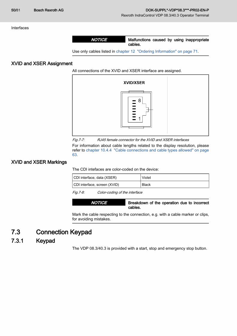
Malfunctions caused by using inappropriatecables.
NOTICE
Use only cables listed in chapter 12 "Ordering Information" on page 71.
XVID and XSER AssignmentAll connections of the XVID and XSER interface are assigned.
Fig.7-7: RJ45 female connector for the XVID and XSER interfacesFor information about cable lengths related to the display resolution, pleaserefer to chapter 10.4.4 "Cable connections and cable types allowed" on page63.
XVID and XSER MarkingsThe CDI intefaces are color-coded on the device:
CDI interface, data (XSER) Violet
CDI interface, screen (XVID) Black
Fig.7-8: Color-coding of the interface
Breakdown of the operation due to incorrectcables.
NOTICE
Mark the cable respecting to the connection, e.g. with a cable marker or clips,for avoiding mistakes.
7.3 Connection Keypad7.3.1 Keypad
The VDP 08.3/40.3 is provided with a start, stop and emergency stop button.
Bosch Rexroth AG DOK-SUPPL*-VDP*08.3***-PR02-EN-P Rexroth IndraControl VDP 08.3/40.3 Operator Terminal
50/81
Interfaces

Fig.7-9: Keypad of the VDP
Death or serious injury caused by wrong han‐dling.
WARNING
● The emergency stop button can be used as operating element in an emer‐gency stop circuit.
● The emergency stop circuit is to be designed by the machine manufac‐turer.
● Only qualified persons may connect the emergency stop button and checkit afterwards.
● The button is to be connected according to the connection scheme chapter7.3.2 "Connection Scheme of the Keypad" on page 52.
● The max. load current is 500 mA.
The emergency stop button is disclosed by the manufacturer as safety com‐ponent according to machinery directive 2006/42/EC (annex V-10, emergencystop devices). The compliance with the directive is proven by adherence to thefollowing European standards:● IEC 60204-1 (safety of machinery – electrical equipment of machines)● IEC 60947-5-1/5 (requirements for control circuit devices, requirements
for emergency stop devices)● ISO 13850 (safety of machinery - emergency stop - principles for design)According to DIN EN ISO13849-1 the B10d value is:
Mechanics Electrics
B10d = 250 000exclusion of failure at < 6050 switching cy‐cles
B10d = 5 000 000exclusion of failure at < 6050 switching cy‐cles
Fig.7-10: Emergency stop button, B10 d value, service life
DOK-SUPPL*-VDP*08.3***-PR02-EN-P Rexroth IndraControl VDP 08.3/40.3 Operator Terminal
Bosch Rexroth AG 51/81
Interfaces

7.3.2 Connection Scheme of the Keypad
S1emergency stop
LED2 LED4
X3 X2
S2 S3 S4
Fig.7-11: Connection Scheme of the Keypad
7.3.3 Pin Assignment of the KeypadPin Function
1 S1 (emergency stop) NC contact 1
2 S1 (emergency stop) NC contact 1
3 S1 (emergency stop) NC contact 2
4 S1 (emergency stop) NC contact 2
5 S2 (white key) NO/NC contact
6 S2 (white key) NO contact
7 S2 (white key) NC contact
8 S3 (black key) NO/NC contact
9 S3 (black key) NO contact
10 S3 (black key) NC contact
Fig.7-12: Pin assignment keypad X3
Pin Function
1 S4 (blue key) NO/NC contact
2 S4 (blue key) NO contact
3 S4 (blue key) NC contact
4 LED2 in S2 (white key) +24 V
5 LED4 in S4 (blue key) +24 V
6 LED2/LED4 -0V
Fig.7-13: Pin assignment keypad X2
Bosch Rexroth AG DOK-SUPPL*-VDP*08.3***-PR02-EN-P Rexroth IndraControl VDP 08.3/40.3 Operator Terminal
52/81
Interfaces

Destruction of screw terminals, insufficientcontact and loss of UL/CSA certification if nocopper wire is used and/or wrong tighteningtorque.
NOTICE
For terminal connectors use copper wire only. Tighten the screws of the screwterminals with a torque of 2.25 lb in (0.25 Nm).
Connector X2, X3 The X2 and X3 connectors are located behind the housing cover, see fig.7-14 "Connector X2, X3 on the VDP 40.3" on page 53.
X3 X2
PIN 1
Fig.7-14: Connector X2, X3 on the VDP 40.3
DOK-SUPPL*-VDP*08.3***-PR02-EN-P Rexroth IndraControl VDP 08.3/40.3 Operator Terminal
Bosch Rexroth AG 53/81
Interfaces

Fig.7-15: Connector X2, X3 on the VDP08.3 - CG device
Fig.7-16: Connector X2, X3 on the VDP 40.3 - CG device
Bosch Rexroth AG DOK-SUPPL*-VDP*08.3***-PR02-EN-P Rexroth IndraControl VDP 08.3/40.3 Operator Terminal
54/81
Interfaces
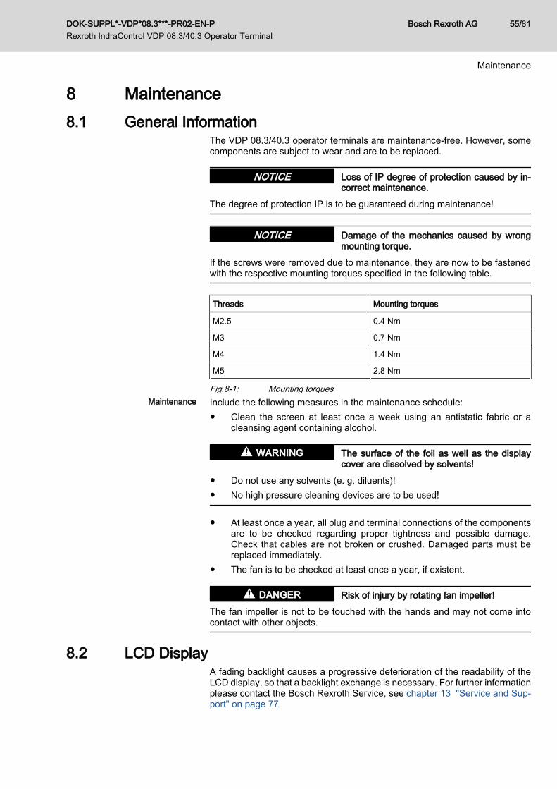
8 Maintenance8.1 General Information
The VDP 08.3/40.3 operator terminals are maintenance-free. However, somecomponents are subject to wear and are to be replaced.
Loss of IP degree of protection caused by in‐correct maintenance.
NOTICE
The degree of protection IP is to be guaranteed during maintenance!
Damage of the mechanics caused by wrongmounting torque.
NOTICE
If the screws were removed due to maintenance, they are now to be fastenedwith the respective mounting torques specified in the following table.
Threads Mounting torques
M2.5 0.4 Nm
M3 0.7 Nm
M4 1.4 Nm
M5 2.8 Nm
Fig.8-1: Mounting torquesMaintenance Include the following measures in the maintenance schedule:
● Clean the screen at least once a week using an antistatic fabric or acleansing agent containing alcohol.
The surface of the foil as well as the displaycover are dissolved by solvents!
WARNING
● Do not use any solvents (e. g. diluents)!● No high pressure cleaning devices are to be used!
● At least once a year, all plug and terminal connections of the componentsare to be checked regarding proper tightness and possible damage.Check that cables are not broken or crushed. Damaged parts must bereplaced immediately.
● The fan is to be checked at least once a year, if existent.
Risk of injury by rotating fan impeller!DANGER
The fan impeller is not to be touched with the hands and may not come intocontact with other objects.
8.2 LCD DisplayA fading backlight causes a progressive deterioration of the readability of theLCD display, so that a backlight exchange is necessary. For further informationplease contact the Bosch Rexroth Service, see chapter 13 "Service and Sup‐port" on page 77.
DOK-SUPPL*-VDP*08.3***-PR02-EN-P Rexroth IndraControl VDP 08.3/40.3 Operator Terminal
Bosch Rexroth AG 55/81
Maintenance

Bosch Rexroth AG DOK-SUPPL*-VDP*08.3***-PR02-EN-P Rexroth IndraControl VDP 08.3/40.3 Operator Terminal
56/81
9 Software9.1 Touch Screen Software
In the VDP 08.3DB and VDP 40.3DI operator displays a touch screen is inte‐grated allowing the operation via the touch-sensitive surface of the display.The touch screen controller communicates with the control cabinet PC via theCDI interface using the USB interface internally in the control cabinet PC.No driver software is to be installed. For more detailed information, please referto the respective documentation of the Rexroth control cabinet PC.
9.2 M-Key-UpperClassFilter9.2.1 General Information
From firmware version 02VRS and higher of the operating system on the controlcabinet PC, the M-Key-UpperClassFilter driver is installed and active ex works.The M-Key-UpperClassFilter driver is used for maintaining the downward com‐patibility of the M-Key-Code when existing software products are used ondevices of the V xx.3 generation. The incoming keyboard data stream is ana‐lyzed and as soon as a M-key-code (F13-F24,...) is detected, the correspondingCtrl-LRShift-Alt-<n> code is inserted into the data stream. This is done in thekernel level of the operating system.
Breakdown of the operation of the USB specialkeyboard due to activated M-Key-UpperClassFilter.
NOTICE
If a USB special keyboard is used, it may be required to deactivate the M-Key-UpperClassFilter, see chapter 9.2 "M-Key-UpperClassFilter" on page 57.
9.2.2 Activation and Deactivation of the M-Key-UpperClassFilterTo activate and to deactivate the filter, the both batch files mkeyfilter-ac-tivate.cmd and mkeyfilter-deactivate.cmd are to be used. The sys‐tem restarts after the execution of the batch files. The batch files are filed in thedirectory Support ▶ MKey-Filter Driver.
DOK-SUPPL*-VDP*08.3***-PR02-EN-P Rexroth IndraControl VDP 08.3/40.3 Operator Terminal
Bosch Rexroth AG 57/81
Software

Bosch Rexroth AG DOK-SUPPL*-VDP*08.3***-PR02-EN-P Rexroth IndraControl VDP 08.3/40.3 Operator Terminal
58/81

10 Y-Repeater10.1 General Information
This chapter describes the functions and the application of the Y-repeater. Twooperator displays can be connected to one control cabinet PC using a Y-re‐peater. It cascades up to four operator displays. All operator displays show thesame screen. The operation is only enabled at one operator display at a time.Use the changeover input for switching to the operation by the other operatordisplay.
10.2 Housing Dimensions of the Y-RepeaterThe Y-repeater is provided for rear panel mounting.
Fig.10-1: Dimensions of the Y-repeater - rear panel
DOK-SUPPL*-VDP*08.3***-PR02-EN-P Rexroth IndraControl VDP 08.3/40.3 Operator Terminal
Bosch Rexroth AG 59/81
Y-Repeater

Fig.10-2: Dimensions of the Y-repeater - side view
Loss of UL compliance if operated without UL-registered housing.
NOTICE
To guarantee an UL-compliant operation, the Y-repeater is to be operated onlywithin an UL-registered housing.
10.3 Switching Times Y-Repeater10.3.1 General Information
If an active operator terminal is disabled it takes some seconds until the enabledscreen can be operated. The time interval is the so-called "switching time". Thisswitching time depends on whether USB devices are connected to "XUSBx"connections and on the used USB mode.In order to get faster values in the standard USB mode, all connected VDPsare to be connected in the standard USB mode. The standard USB mode canbe used up to a cable length of 30 m, see also chapter 7.2.3 "S1 DIP switch".The values specified in this chapter are valid for devices from index 201 andhigher (see type plate of the Y-repeater).
Bosch Rexroth AG DOK-SUPPL*-VDP*08.3***-PR02-EN-P Rexroth IndraControl VDP 08.3/40.3 Operator Terminal
60/81
Y-Repeater

10.3.2 Switching Times without Devices on the USB ConnectionsSwitching condition Switching time in standard
USB modeSwitching time in extendedUSB mode
Switching to an other oper‐ator terminal
Up to 5 seconds. Up to 10 seconds.
Fig.10-3: Switching times without devices connected to the USB connections
10.3.3 Switching Times with Devices on the USB ConnectionsSwitching condition Switching time in standard
USB modeSwitching time in extendedUSB mode
Switching to an operatorterminal to which only al‐ready known USB devicesare connected on the sameUSB port.
Up to 5 seconds. Up to 10 seconds.
Switching to an operatorterminal to which already anew USB device has beenconnected.
Up to 30 seconds.(time until the USB deviceis correctly installed byWindows)
Up to 30 seconds.(time until the USB device iscorrectly installed by Win‐dows)
Fig.10-4: Switching times with devices connected to the USB connections
Incorrect operation at the VDP possible whenswitching the Y-repeater.
NOTICE
The devices connected to the XUSBx USB connections can be operated up tothree seconds at the disabled VDP. The key operation and touch operation ofthe deselected VDP is immediately disabled.
10.4 Interfaces on the Y-Repeater10.4.1 View on the Connector Panel
The connections are located at the front panel of the Y-repeater.
DOK-SUPPL*-VDP*08.3***-PR02-EN-P Rexroth IndraControl VDP 08.3/40.3 Operator Terminal
Bosch Rexroth AG 61/81
Y-Repeater
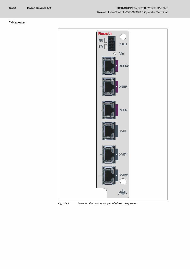
Fig.10-5: View on the connector panel of the Y-repeater
Bosch Rexroth AG DOK-SUPPL*-VDP*08.3***-PR02-EN-P Rexroth IndraControl VDP 08.3/40.3 Operator Terminal
62/81
Y-Repeater

10.4.2 Description of the InterfacesDesignationat the housing
Connection type Connector type (inte‐grated)
Mating connector orcable from outside
X1S1 24 V voltage supplyDigital 24 V input
Phönix connector strip,4-pin, MC1,5/4-G-3,5THT
Phönix female connec‐tor strip,4-pin, FK-MCP 1,5/4-ST-3,5
XSERXVID
CDI interface to thecontrol cabinet PC
Two RJ45 female con‐nectors
Two RJ45 connectors
XSER1XVID1
CDI interface to theVDP 08.3/40.3 no. 1
Two RJ45 female con‐nectors
Two RJ45 connectors
XSER2XVID2
CDI interface to theVDP 08.3/40.3 no. 2
Two RJ45 female con‐nectors
Two RJ45 connectors
Fig.10-6: Connections on the Y-repeater
10.4.3 CDI InterfacesThe Y-repeater is connected to the control cabinet PC and to two operator dis‐plays via the CDI interfaces (XSER, XVID, XSER1, XVID1, XSER2, XVID2).
Connection Function
XSER, XVID CDI interface to the control cabinet PC
XSER1, XVID1 CDI interface to the VDP 08.3/40.3 no. 1
XSER2, XVID2 CDI interface to the VDP 08.3/40.3 no. 2
Fig.10-7: Assignment of the three CDI interfaces
10.4.4 Cable connections and cable types allowedThe chapter "Ordering Information" contains connecting cables of differentlenghts.The cable lengths allowed at the Y-repeater depend on the display resolutionset (depends on the VDP).A cable length of 100 m max. (from control cabinet to VDP) is possible whenusing a XGA resolution. Also refer to the different operation modes of the CDIinterface.
Cable lengths The cables on the Y-repeaters may not exceed the following lengths:
Cable lengthsSVGA800 × 600 pix‐els
XGA1024 × 768 pixels
SXGA1280 × 1024 pix‐els
Cable lengths between thecontrol cabinet PC and theVDPwithout Y-repeater
< 80 meters < 70 meters < 60 meters
Cable lengths between con‐trol cabinet PC and Y-repeat‐er
< 80 meters < 70 meters < 60 meters
DOK-SUPPL*-VDP*08.3***-PR02-EN-P Rexroth IndraControl VDP 08.3/40.3 Operator Terminal
Bosch Rexroth AG 63/81
Y-Repeater

Cable lengthsSVGA800 × 600 pix‐els
XGA1024 × 768 pixels
SXGA1280 × 1024 pix‐els
Cable lengths between Y-re‐peater and VDP
< 80 meters < 70 meters < 60 meters
Total cable length betweencontrol cabinet PC and VDPwith Y-repeater
< 100 meters < 100 meters < 100 meters
Fig.10-8: Cable lengths allowed for VAC01.1S-YD1-NNNN
Malfunctions if the total of all cable lengths ex‐ceeds 100 m.
NOTICE
The total of all cable lengths between the control cabinet PC and the operatorVDP may not exceed 100 m.
If the total of all cable lengths between control cabinet PC and operator displayexceeds 30 m, the data transmission for USB devices connected to the VDP islimited. See also chapter 7.2.3 "S1 DIP switch".
Fig.10-9: Maximum cable length between operator display and control cabinet PCFurther cable lengths on request.
10.4.5 24 V Supply Voltage and Digital 24 V Input The power consumption of the Y-repeater is 4 W.
Fig.10-10: Assignment of the digital 24 V input
Bosch Rexroth AG DOK-SUPPL*-VDP*08.3***-PR02-EN-P Rexroth IndraControl VDP 08.3/40.3 Operator Terminal
64/81
Y-Repeater
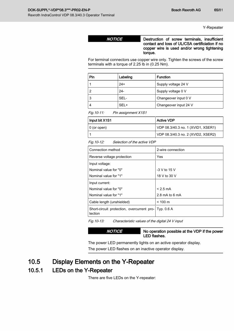
Destruction of screw terminals, insufficientcontact and loss of UL/CSA certificiation if nocopper wire is used and/or wrong tighteningtorque.
NOTICE
For terminal connectors use copper wire only. Tighten the screws of the screwterminals with a torque of 2.25 lb in (0.25 Nm).
Pin Labeling Function
1 24+ Supply voltage 24 V
2 24- Supply voltage 0 V
3 SEL- Changeover input 0 V
4 SEL+ Changeover input 24 V
Fig.10-11: Pin assignment X1S1
Input bit X1S1 Active VDP
0 (or open) VDP 08.3/40.3 no. 1 (XVID1, XSER1)
1 VDP 08.3/40.3 no. 2 (XVID2, XSER2)
Fig.10-12: Selection of the active VDP
Connection method 2-wire connection
Reverse voltage protection Yes
Input voltage:Nominal value for "0"Nominal value for "1"
-3 V to 15 V18 V to 30 V
Input current:Nominal value for "0"Nominal value for "1"
< 2.5 mA2.8 mA to 6 mA
Cable length (unshielded) < 100 m
Short-circuit protection, overcurrent pro‐tection
Typ. 0.6 A
Fig.10-13: Characteristic values of the digital 24 V input
No operation possible at the VDP if the powerLED flashes.
NOTICE
The power LED permanently lights on an active operator display.The power LED flashes on an inactive operator display.
10.5 Display Elements on the Y-Repeater10.5.1 LEDs on the Y-Repeater
There are five LEDs on the Y-repeater:
DOK-SUPPL*-VDP*08.3***-PR02-EN-P Rexroth IndraControl VDP 08.3/40.3 Operator Terminal
Bosch Rexroth AG 65/81
Y-Repeater
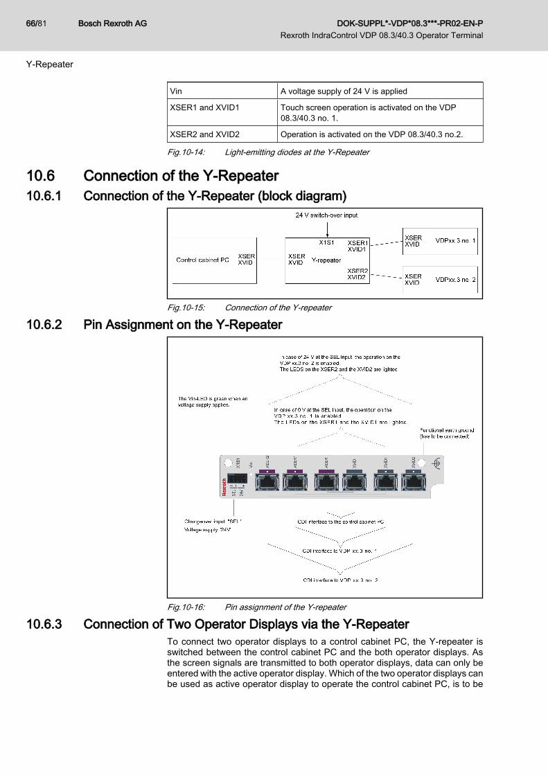
Vin A voltage supply of 24 V is applied
XSER1 and XVID1 Touch screen operation is activated on the VDP08.3/40.3 no. 1.
XSER2 and XVID2 Operation is activated on the VDP 08.3/40.3 no.2.
Fig.10-14: Light-emitting diodes at the Y-Repeater
10.6 Connection of the Y-Repeater10.6.1 Connection of the Y-Repeater (block diagram)
Fig.10-15: Connection of the Y-repeater
10.6.2 Pin Assignment on the Y-Repeater
Fig.10-16: Pin assignment of the Y-repeater
10.6.3 Connection of Two Operator Displays via the Y-RepeaterTo connect two operator displays to a control cabinet PC, the Y-repeater isswitched between the control cabinet PC and the both operator displays. Asthe screen signals are transmitted to both operator displays, data can only beentered with the active operator display. Which of the two operator displays canbe used as active operator display to operate the control cabinet PC, is to be
Bosch Rexroth AG DOK-SUPPL*-VDP*08.3***-PR02-EN-P Rexroth IndraControl VDP 08.3/40.3 Operator Terminal
66/81
Y-Repeater

selected with a 24 V signal, see chapter 10.4.5 "24 V Supply Voltage and Digital24 V Input " on page 64.
Missing screen output or incorrect screen res‐olution if VDPs with different resolution areconnected.
NOTICE
Only VDP devices with the same resolution may be connected to a Y-repeater.
Missing screen output or incorrect screen res‐olution if the Y-repeater is switched duringbooting.
NOTICE
While booting the control cabinet PC, switching from one to another operatordisplay is not permitted since the display resolution will be wrong or not beidentified.
Missing screen output or incorrect screen res‐olution if the voltage supply of the VDP isswitched on after switching on the control cab‐inet PC.
NOTICE
The operator displays are to be supplied with voltage either before or at leastat the same time as the control cabinet PC.
10.6.4 Connection of Four Operator Displays via Three Y-RepeatersY-repeaters can be used in a cascaded way: Maximum two further Y-repeaterscan be connected to a Y-repeater. Thus, four operator displays can be con‐nected to one control cabinet PC. As the screen signals are transmitted to allthe operator displays, data can only be entered using the active operator dis‐play. Which of the four operator displays can be used as active operator displayto operate the control cabinet PC is to be selected with a 24 V signal. For theswitching, please refer to fig. 10-17 "Connection of the Y-repeater with fouroperator displays" on page 67.
Fig.10-17: Connection of the Y-repeater with four operator displays
SEL1 SEL2 Operator display selected
0 V 0 V VDP 08.3/40.3 no. 1
0 V 24 V VDP 08.3/40.3 no. 2
24 V 0 V VDP 08.3/40.3 no. 3
24 V 24 V VDP 08.3/40.3 no. 4
Fig.10-18: 24 V input signal circuit in case of four Y-repeaters
DOK-SUPPL*-VDP*08.3***-PR02-EN-P Rexroth IndraControl VDP 08.3/40.3 Operator Terminal
Bosch Rexroth AG 67/81
Y-Repeater

Bosch Rexroth AG DOK-SUPPL*-VDP*08.3***-PR02-EN-P Rexroth IndraControl VDP 08.3/40.3 Operator Terminal
68/81
11 Environmental Protection and Disposal11.1 Environmental Protection
Production Processes The products are made with energy- and resource-optimized production pro‐cesses which allow re-using and recycling the resulting waste. We regularly tryto replace pollutant-loaded raw materials and supplies by more environment-friendly alternatives.
No Release of Hazardous Substan‐ces
Our products do not contain any hazardous substances which may be releasedin the case of appropriate use. Normally, our products will not have any negativinfluences on the environment.
Significant Components Basically, out products contain the following components:Electronic devices Motors∙ steel ∙ steel∙ aluminum ∙ aluminum∙ copper ∙ copper∙ synthetic materials ∙ brass∙ electronic components and modules ∙ magnetic materials ∙ electronic components and modules
11.2 DisposalReturn of Products Our products can be returned to our premises free of charge for disposal. It is
a precondition, however, that the products are free of oil, grease or other dirt.Furthermore, the products returned for disposal must not contain any undueforeign material or foreign components.Send the products ”free domicile” to the following address: Bosch Rexroth AG Electric Drives and Controls Buergermeister-Dr.-Nebel-Strasse 2 97816 Lohr am Main, Germany
Packaging The packaging materials consist of cardboard, wood and polystyrene. Thesematerials can be recycled anywhere without any problem.For ecological reasons, please refrain from returning the empty packages tous.
Recycling Most of the products can be recycled due to their high content of metal. In orderto recycle the metal in the best possible way, the products must be disassem‐bled into individual modules.Metals contained in electric and electronic modules can also be recycled bymeans of special separation processes.Products made of plastics can contain flame retardants. These plastic parts arelabeled according to EN ISO 1043. They have to be recycled separately ordisposed of according to the valid legal requirements.If the products contain batteries or accumulators, remove them before recyclingand dispose of them separately.
DOK-SUPPL*-VDP*08.3***-PR02-EN-P Rexroth IndraControl VDP 08.3/40.3 Operator Terminal
Bosch Rexroth AG 69/81
Environmental Protection and Disposal

Bosch Rexroth AG DOK-SUPPL*-VDP*08.3***-PR02-EN-P Rexroth IndraControl VDP 08.3/40.3 Operator Terminal
70/81

12 Ordering Information12.1 Type Designation Code12.1.1 General Information
The VDP 08.3 and VDP 40.3 displays are available as different variants ac‐cording to the following type designation codes.
12.1.2 VDP 08.3
1 2 3 4 6 7 8 91 05 1 2 3 4 6 7 8 9
2 05 1 2
Example:column
V D P 0 8 . 3 D P N - D 1 - N N - N N
ProductVDP. . . . . . . . = VDP
Line08 . . . . . . . . . . . . . . . = 08
Design3 . . . . . . . . . . . . . . . . . . . . . . = 3
Front panel and display Rexroth Design8.4" touch screen with
touch screen with
Additional option. . . . . . . . . . . . . . . . . . . . .= N
Control panel interfaceCDI. . . . . . . . . . . . . . . . . . . . . . . . . . . . . = D1
Interface. . . . . . . . . . . . . . . . . . . . . . . . . . . . . . = NN
Other design. . . . . . . . . . . . . . . . . . . . . . . . . . =
NoteOther design "CG" is only available with front panel "DP".
1
1
switching elements8.4"
Without
Without
In the system housingWithout
Abbrev.
front USB
DP
EF
CG
. . . . . . . .
. . . . . . . . . . . . . .
. . . . . . . . NN. . . . . . . . . . . . . . . . . . . . . . . . . . . . . =
=
=
Fig.12-1: Type designation code VDP 08.3
DOK-SUPPL*-VDP*08.3***-PR02-EN-P Rexroth IndraControl VDP 08.3/40.3 Operator Terminal
Bosch Rexroth AG 71/81
Ordering Information

12.1.3 VDP 40.3
Fig.12-2: Type designation code VDP 40.3
12.2 Accessories12.2.1 Y-Repeater
Connection unit to connect two operating units (VDP 08.3/40.3) with the sameresolution and of the same design with a control cabinet PC (VSB 40.3 orVPB 40.3).
Bosch Rexroth AG DOK-SUPPL*-VDP*08.3***-PR02-EN-P Rexroth IndraControl VDP 08.3/40.3 Operator Terminal
72/81
Ordering Information

Order code Parts number Description
VAC01.1S-YD1-NNNN R911171187 Y-repeater for the CDI interface
Fig.12-3: Y-Repeater
12.2.2 External 24 V Power Supply UnitExternal 24 V power supply unit for VDP 08.3/40.3.
Order code Parts number Description
VAP01.1H-W23-024-010-NN R911171065 External 24 V power supply unit for the IndraControl V de‐vices
Fig.12-4: External 24 V power supply unit for VDP 08.3/40.3
12.2.3 Uninterruptible Power SupplyOrder code Parts number Description
VAU01.1U-024-024-240-NN R911171024 Uninterruptible Power Supply (UPS)DC 24 V, 240 watt with USB interface
Fig.12-5: UPS
12.2.4 Connecting Cable for CDI InterfaceConnecting cable for the connection between control cabinet PC and operatordisplay (VDP 08.3/40.3).
Order code Parts number Description
RKB0008/000,5 (*******-*******-*******) R911171484 Length: 0.5 m
RKB0008/001,0 (*******-*******-*******) R911171485 Length: 1 m
RKB0008/002,5 (*******-*******-*******) R911170151 Length: 2.5 m
RKB0008/005,0 (*******-*******-*******) R911170152 Length: 5 m
RKB0008/010,0 (*******-*******-*******) R911170153 Length: 10 m
RKB0008/015,0 (*******-*******-*******) R911171183 Length: 15 m
RKB0008/020,0 (*******-*******-*******) R911171184 Length: 20 m
RKB0008/025,0 (*******-*******-*******) R911170154 Length: 25 m
RKB0008/030,0 (*******-*******-*******) R911171381 Length: 30 m
RKB0008/035,0 (*******-*******-*******) R911171369 Length: 35 m
RKB0008/040,0 (*******-*******-*******) R911171382 Length: 40 m
RKB0008/050,0 (*******-*******-*******) R911171383 Length: 50 m
Fig.12-6: Connecting cables to control cabinet PC, panel PC and to operator dis‐play
Further cable lengths on request.
No operation or no screen output if only onecable is used.
NOTICE
Two cables are always required to establish a connection between the VxB andthe VDP.
DOK-SUPPL*-VDP*08.3***-PR02-EN-P Rexroth IndraControl VDP 08.3/40.3 Operator Terminal
Bosch Rexroth AG 73/81
Ordering Information
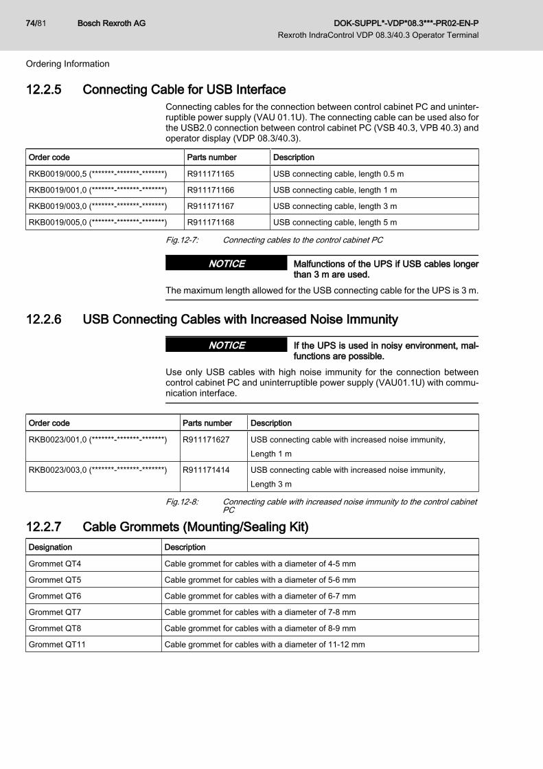
12.2.5 Connecting Cable for USB InterfaceConnecting cables for the connection between control cabinet PC and uninter‐ruptible power supply (VAU 01.1U). The connecting cable can be used also forthe USB2.0 connection between control cabinet PC (VSB 40.3, VPB 40.3) andoperator display (VDP 08.3/40.3).
Order code Parts number Description
RKB0019/000,5 (*******-*******-*******) R911171165 USB connecting cable, length 0.5 m
RKB0019/001,0 (*******-*******-*******) R911171166 USB connecting cable, length 1 m
RKB0019/003,0 (*******-*******-*******) R911171167 USB connecting cable, length 3 m
RKB0019/005,0 (*******-*******-*******) R911171168 USB connecting cable, length 5 m
Fig.12-7: Connecting cables to the control cabinet PC
Malfunctions of the UPS if USB cables longerthan 3 m are used.
NOTICE
The maximum length allowed for the USB connecting cable for the UPS is 3 m.
12.2.6 USB Connecting Cables with Increased Noise Immunity
If the UPS is used in noisy environment, mal‐functions are possible.
NOTICE
Use only USB cables with high noise immunity for the connection betweencontrol cabinet PC and uninterruptible power supply (VAU01.1U) with commu‐nication interface.
Order code Parts number Description
RKB0023/001,0 (*******-*******-*******) R911171627 USB connecting cable with increased noise immunity,Length 1 m
RKB0023/003,0 (*******-*******-*******) R911171414 USB connecting cable with increased noise immunity,Length 3 m
Fig.12-8: Connecting cable with increased noise immunity to the control cabinetPC
12.2.7 Cable Grommets (Mounting/Sealing Kit)Designation Description
Grommet QT4 Cable grommet for cables with a diameter of 4-5 mm
Grommet QT5 Cable grommet for cables with a diameter of 5-6 mm
Grommet QT6 Cable grommet for cables with a diameter of 6-7 mm
Grommet QT7 Cable grommet for cables with a diameter of 7-8 mm
Grommet QT8 Cable grommet for cables with a diameter of 8-9 mm
Grommet QT11 Cable grommet for cables with a diameter of 11-12 mm
Bosch Rexroth AG DOK-SUPPL*-VDP*08.3***-PR02-EN-P Rexroth IndraControl VDP 08.3/40.3 Operator Terminal
74/81
Ordering Information

Designation Description
Grommet QT12 Cable grommet for cables with a diameter of 12-13 mm
Grommet QTB Blind grommet
Fig.12-9: Cable grommets for VDP 08.3/40.3
DOK-SUPPL*-VDP*08.3***-PR02-EN-P Rexroth IndraControl VDP 08.3/40.3 Operator Terminal
Bosch Rexroth AG 75/81
Ordering Information

Bosch Rexroth AG DOK-SUPPL*-VDP*08.3***-PR02-EN-P Rexroth IndraControl VDP 08.3/40.3 Operator Terminal
76/81

13 Service and SupportOur service helpdesk at our headquarters in Lohr, Germany and our worldwideservice will assist you with all kinds of enquiries. You can reach us around theclock - even on weekend and on holidays.
HelpdeskService HotlineWorldwide
Phone +49 (0) 9352 40 50 60 Outwith Germany please con‐tact our sales/service office inyour area first.For hotline numbers refer tothe sales office addresses onthe Internet.
Fax +49 (0) 9352 40 49 41
E-mail [email protected]
Internethttp://www.boschrexroth.comYou will also find additional notes regarding service, mainte‐nance (e.g. delivery addresses) and training.
Preparing Information For quick and efficient help please have the following information ready:● Detailed description of the fault and the circumstances● Information on the type plate of the affected products, especially type co‐
des and serial numbers● Your phone, fax numbers and e-mail address so we can contact you in
case of questions.
DOK-SUPPL*-VDP*08.3***-PR02-EN-P Rexroth IndraControl VDP 08.3/40.3 Operator Terminal
Bosch Rexroth AG 77/81
Service and Support

Bosch Rexroth AG DOK-SUPPL*-VDP*08.3***-PR02-EN-P Rexroth IndraControl VDP 08.3/40.3 Operator Terminal
78/81

IndexSymbols24 V power supply unit........................................ 73
AAccessories..................................................... 7, 72
Cable grommets ........................................... 75Ambient conditions
Ambient conditions ....................................... 22Appropriate use..................................................... 9
Use cases ...................................................... 9
BB10d value.......................................................... 23Backlight....................................................... 25, 41Backlight switch-off............................................. 41
CCable grommet................................................... 34Cable grommets.................................................. 74Cable types on the Y-repeater............................ 63CDI interface....................................................... 49CDI interfaces on the Y-repeater........................ 63CE marking......................................................... 23Changeover input.......................................... 64, 65Connecting cable to control cabinet PC, panelPC and operator display..................................... 73Connector panel.................................................. 45Connector X2, X3................................................ 53Contained substances
see "Significant components" ....................... 69Cover
Dismounting ................................................. 33Fastening ..................................................... 35
DDC 24 V voltage supply...................................... 47Declaration of conformity.................................... 23Digital 24 V input................................................. 64Dimensions......................................................... 27
Housing dimensions VDP 08.3 .................... 27Housing dimensions VDP 40.3 .................... 30Installation notes .......................................... 32
DIP switch S1...................................................... 46Display and operating components..................... 41Disposal.............................................................. 69Drive system....................................................... 11
EElectrical wiring................................................... 37Electric drive system........................................... 11Environmental protection.................................... 69Extended USB mode.......................................... 47
EExternal 24 V power supply unit......................... 73
FFour displays on the Y-repeater.......................... 67Front panel.......................................................... 21
HHazardous substances....................................... 69Housing dimensions............................................ 27
IInappropriate use................................................ 10
Consequences, exclusion of liability .............. 9Installation..................................................... 27, 32Interface
XVID interface .............................................. 49Interfaces............................................................ 45
XUSB interfaces ........................................... 48XVID interface .............................................. 49
Interfaces on the Y-repeater............................... 61CDI interface ................................................ 63Changeover input ......................................... 64Digital input .................................................. 64
KKeyboard............................................................. 57Keypad................................................................ 50
Pin assignment ............................................. 52Key positions....................................................... 43
LLEDs
Displays on the Y-repeater ........................... 65Operating and error displays on the VDP ... . 41
LEDs on the Y-repeater...................................... 65
MMaintenance....................................................... 55
General information ...................................... 55LCD display .................................................. 55
M-Key-UpperClassFilter...................................... 57Mounting....................................................... 27, 32Mounting/sealing kit............................................ 74Mounting torques................................................ 35
OOperating and error displays............................... 41Operation............................................................ 43Operation modes................................................ 46Ordering information........................................... 71
DOK-SUPPL*-VDP*08.3***-PR02-EN-P Rexroth IndraControl VDP 08.3/40.3 Operator Terminal
Bosch Rexroth AG 79/81
Index

PPackaging........................................................... 69PELV................................................................... 15Pin assignment keypad....................................... 52Pin assignment on the Y-repeater...................... 66Position of the keys............................................. 43Production processes......................................... 69Protective extra-low voltage................................ 15
RRecycling............................................................ 69Return of products.............................................. 69
SS1 DIP switch...................................................... 46Safety instructions for electric drives and con‐trols..................................................................... 11Significant components....................................... 69Software.............................................................. 57Standards............................................................ 22Standard USB mode........................................... 46State-of-the-art ..................................................... 9Support
see Service Hotline ...................................... 77Switching times................................................... 60Switch-off of the backlight................................... 41System presentation............................................. 5
Brief description ............................................. 5Commissioning ............................................... 7Variants .......................................................... 5
TTechnical data............................................... 21, 22
Front panel ................................................... 21Used standards ............................................ 22Voltage supply .............................................. 21Wear parts .................................................... 25
Touch screen...................................................... 43Touch screen software........................................ 57Two displays on the Y-repeater.......................... 66Type designation code........................................ 71
UUL/CSA certified................................................. 24
UUninterrruptible power supply............................. 73UPS..................................................................... 73UPS wiring.......................................................... 39Use
Appropriate use .............................................. 9Inappropriate use ......................................... 10
Used standards................................................... 23
VVDP 08.3............................................................... 6VDP 40.3............................................................... 7VESA bracket................................................ 35, 36Voltage supply.................................................... 21Voltage supply (DC 24 V)................................... 47
WWear parts.......................................................... 25Wiring 230 V....................................................... 37Wiring 400 V....................................................... 38
XX1S1
Pin assignment ............................................. 65XUSB interfaces............................................ 48, 49
YY-repeater........................................... 5, 59, 72, 73
Cable types .................................................. 63Connecting two operator displays ................ 66Connection ................................................... 66Connection of four operator displays ........... 67Connector panel ........................................... 61Housing dimensions ..................................... 59Interfaces ..................................................... 61LEDs ............................................................ 65Pin assignment ............................................. 66Switching times ............................................ 60UL ................................................................. 60
Bosch Rexroth AG DOK-SUPPL*-VDP*08.3***-PR02-EN-P Rexroth IndraControl VDP 08.3/40.3 Operator Terminal
80/81
Index
P

Notes
DOK-SUPPL*-VDP*08.3***-PR02-EN-P Rexroth IndraControl VDP 08.3/40.3 Operator Terminal
Bosch Rexroth AG 81/81

Printed in GermanyDOK-SUPPL*-VDP*08.3***-PR02-EN-PR911328472
Bosch Rexroth AGElectric Drives and ControlsP.O. Box 13 5797803 Lohr, GermanyBgm.-Dr.-Nebel-Str. 297816 Lohr, GermanyTel. +49 (0)93 52-40-0Fax +49 (0)93 52-48 85www.boschrexroth.com