rexroth indracontrol · rexroth indracontrol vcp 20 industrial hydraulics electric drives and...
TRANSCRIPT
Rexroth IndraControl VCP 20
IndustrialHydraulics
Electric Drivesand Controls
Linear Motion and Assembly Technologies Pneumatics
ServiceAutomation
MobileHydraulics
Rexroth IndraControlIndraLogic L40System Description
R911309372Edition 01
Operating and Programming Guide
About this Documentation IndraLogic L40
DOK-CONTRL-IC*L40*****-AW01-EN-P
Rexroth IndraControl
IndraLogic L40
System Description
Operating and Programming Guide
DOK-CONTRL-IC*L40*****-AW01-EN-P
Document Number, 120-0401-B322-01/EN
This documentation gives an overview of the system componentsbelonging to the control IndraLogic L40 and describes its projecting andprogramming.
Description ReleaseDate
Notes
120-0401-B322-01/EN 11/04 First Edition
2004, Bosch Rexroth AG
Copying this document, giving it to others and the use or communicationof the contents thereof without express authority, are forbidden. Offendersare liable for the payment of damages. All rights are reserved in the eventof the grant of a patent or the registration of a utility model or design(DIN 34-1).
The specified data is for product description purposes only and may notbe deemed to be guaranteed unless expressly confirmed in the contract.All rights are reserved with respect to the content of this documentationand the availability of the product.
Bosch Rexroth AGBgm.-Dr.-Nebel-Str. 2 • D-97816 Lohr a. Main
Telephone +49 (0)93 52/40-0 • Tx 68 94 21 • Fax +49 (0)93 52/40-48 85
http://www.boschrexroth.com/
Dept. BRC/EPY (NH)
This document has been printed on chlorine-free bleached paper.
Title
Type of Documentation
Document Typecode
Internal File Reference
Purpose of Documentation
Record of Revisions
Copyright
Validity
Published by
Note
IndraLogic L40 Contents I
DOK-CONTRL-IC*L40*****-AW01-EN-P
Contents
1 System Overview 1-1
1.1 Components ................................................................................................................................. 1-1
1.2 Further Documentation ................................................................................................................. 1-1
2 Important Directions for Use 2-1
2.1 Appropriate Use............................................................................................................................ 2-1
Introduction .............................................................................................................................. 2-1
Areas of Use and Application .................................................................................................. 2-2
2.2 Inappropriate Use ......................................................................................................................... 2-2
3 Safety Instructions for Electric Drives and Controls 3-1
3.1 Introduction ................................................................................................................................... 3-1
3.2 Explanations ................................................................................................................................. 3-1
3.3 Hazards by Improper Use............................................................................................................. 3-2
3.4 General Information ...................................................................................................................... 3-3
3.5 Protection Against Contact with Electrical Parts........................................................................... 3-4
3.6 Protection Against Electric Shock by Protective Low Voltage (PELV) ......................................... 3-5
3.7 Protection Against Dangerous Movements .................................................................................. 3-6
3.8 Protection Against Magnetic and Electromagnetic Fields During Operation andMounting ....................................................................................................................................... 3-8
3.9 Protection Against Contact with Hot Parts.................................................................................... 3-9
3.10 Protection During Handling and Mounting.................................................................................... 3-9
3.11 Battery Safety ............................................................................................................................. 3-10
3.12 Protection Against Pressurized Systems.................................................................................... 3-10
4 Projecting and Programming 4-1
4.1 Overview....................................................................................................................................... 4-1
4.2 Projecting with IndraWorks........................................................................................................... 4-1
Start IndraWorks...................................................................................................................... 4-1
Create New IndraLogic L40 Project......................................................................................... 4-2
Inputs in the Wizard................................................................................................................. 4-4
Configure Onboard I/O ............................................................................................................ 4-7
Projecting Inline Modules ........................................................................................................ 4-9
Configuring Profibus DP ........................................................................................................ 4-11
4.3 PLC Programming with IndraLogic............................................................................................. 4-19
Overview................................................................................................................................ 4-19
Target Settings ...................................................................................................................... 4-20
Task Configuration................................................................................................................. 4-21
PLC Configuration ................................................................................................................. 4-22
II Contents IndraLogic L40
DOK-CONTRL-IC*L40*****-AW01-EN-P
Library Manager..................................................................................................................... 4-23
Create a PLC Program .......................................................................................................... 4-24
Save IndraLogic Project Data................................................................................................ 4-24
4.4 Download and Commissioning ................................................................................................... 4-25
Load Configurations and PLC Program in the Control .......................................................... 4-25
Online Functions.................................................................................................................... 4-25
5 Further Functions 5-1
5.1 Firmware Management................................................................................................................. 5-1
5.2 Import IndraLogic Project File....................................................................................................... 5-1
5.3 IndraLogic Functions .................................................................................................................... 5-2
6 Libraries 6-1
6.1 Overview....................................................................................................................................... 6-1
6.2 BuepE_Client................................................................................................................................ 6-2
General .................................................................................................................................... 6-2
BuepE_Client........................................................................................................................... 6-2
6.3 IL_VCP_DP................................................................................................................................... 6-5
Overview.................................................................................................................................. 6-5
VCP_PBS16_A4096................................................................................................................ 6-5
VCP_PBS32_A4096................................................................................................................ 6-6
VCP_PBS32_A65536.............................................................................................................. 6-7
6.4 RIL_L40_Util ................................................................................................................................. 6-8
Overview.................................................................................................................................. 6-8
IL_GetStateFan ....................................................................................................................... 6-8
IL_GetTemp............................................................................................................................. 6-8
IL_GetTempWarning ............................................................................................................... 6-9
6.5 RIL_ProfibusDP .......................................................................................................................... 6-10
Overview................................................................................................................................ 6-10
Slave Diagnostic Data According to the Profibus DP Standard ............................................ 6-11
General Field Bus Diagnosis ................................................................................................. 6-13
Data Types ............................................................................................................................ 6-14
Function Blocks ..................................................................................................................... 6-18
Functions ............................................................................................................................... 6-27
7 Display and Operating Components 7-1
7.1 Display and Operator Keys........................................................................................................... 7-1
7.2 Reset Button and Light-Emitting Diode ........................................................................................ 7-2
7.3 Display Possibilities ...................................................................................................................... 7-3
Default and Status Displays .................................................................................................... 7-3
Default Menu ........................................................................................................................... 7-5
PLC Menu................................................................................................................................ 7-8
Inline Menu .............................................................................................................................. 7-9
PROFIBUS DP Menu .............................................................................................................. 7-9
Special Cases.......................................................................................................................... 7-9
IndraLogic L40 Contents III
DOK-CONTRL-IC*L40*****-AW01-EN-P
8 Technical Data 8-1
8.1 Equipment..................................................................................................................................... 8-1
8.2 Power Data ................................................................................................................................... 8-1
9 List of Figures 9-1
10 Index 10-1
11 Service & Support 11-1
11.1 Helpdesk..................................................................................................................................... 11-1
11.2 Service-Hotline ........................................................................................................................... 11-1
11.3 Internet........................................................................................................................................ 11-1
11.4 Vor der Kontaktaufnahme... - Before contacting us... ................................................................ 11-1
11.5 Kundenbetreuungsstellen - Sales & Service Facilities ............................................................... 11-2

IV Contents IndraLogic L40
DOK-CONTRL-IC*L40*****-AW01-EN-P
IndraLogic L40 System Overview 1-1
DOK-CONTRL-IC*L40*****-AW01-EN-P
1 System Overview
1.1 Components
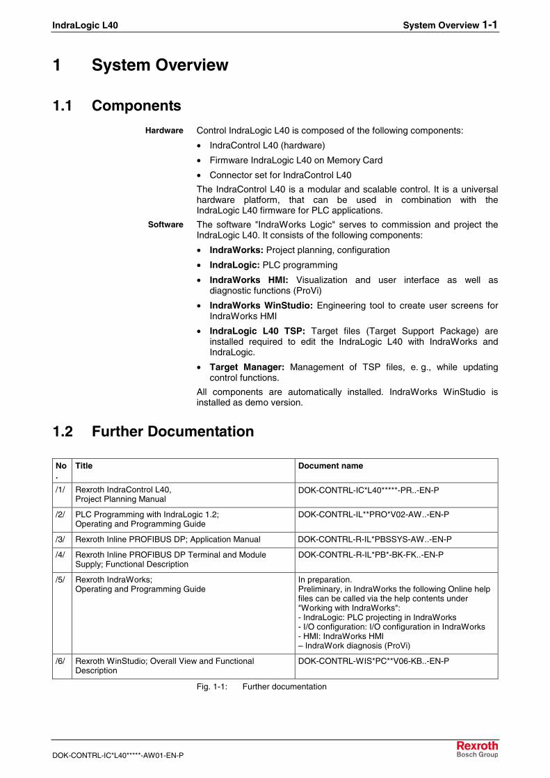
Control IndraLogic L40 is composed of the following components:
• IndraControl L40 (hardware)
• Firmware IndraLogic L40 on Memory Card
• Connector set for IndraControl L40
The IndraControl L40 is a modular and scalable control. It is a universalhardware platform, that can be used in combination with theIndraLogic L40 firmware for PLC applications.
The software "IndraWorks Logic" serves to commission and project theIndraLogic L40. It consists of the following components:
• IndraWorks: Project planning, configuration
• IndraLogic: PLC programming
• IndraWorks HMI: Visualization and user interface as well asdiagnostic functions (ProVi)
• IndraWorks WinStudio: Engineering tool to create user screens forIndraWorks HMI
• IndraLogic L40 TSP: Target files (Target Support Package) areinstalled required to edit the IndraLogic L40 with IndraWorks andIndraLogic.
• Target Manager: Management of TSP files, e. g., while updatingcontrol functions.
All components are automatically installed. IndraWorks WinStudio isinstalled as demo version.
1.2 Further Documentation
No.
Title Document name
/1/ Rexroth IndraControl L40,Project Planning Manual
DOK-CONTRL-IC*L40*****-PR..-EN-P
/2/ PLC Programming with IndraLogic 1.2;Operating and Programming Guide
DOK-CONTRL-IL**PRO*V02-AW..-EN-P
/3/ Rexroth Inline PROFIBUS DP; Application Manual DOK-CONTRL-R-IL*PBSSYS-AW..-EN-P
/4/ Rexroth Inline PROFIBUS DP Terminal and ModuleSupply; Functional Description
DOK-CONTRL-R-IL*PB*-BK-FK..-EN-P
/5/ Rexroth IndraWorks;Operating and Programming Guide
In preparation.Preliminary, in IndraWorks the following Online helpfiles can be called via the help contents under"Working with IndraWorks":- IndraLogic: PLC projecting in IndraWorks- I/O configuration: I/O configuration in IndraWorks- HMI: IndraWorks HMI– IndraWork diagnosis (ProVi)
/6/ Rexroth WinStudio; Overall View and FunctionalDescription
DOK-CONTRL-WIS*PC**V06-KB..-EN-P
Fig. 1-1: Further documentation
Hardware
Software

1-2 System Overview IndraLogic L40
DOK-CONTRL-IC*L40*****-AW01-EN-P
IndraLogic L40 Important Directions for Use 2-1
DOK-CONTRL-IC*L40*****-AW01-EN-P
2 Important Directions for Use
2.1 Appropriate Use
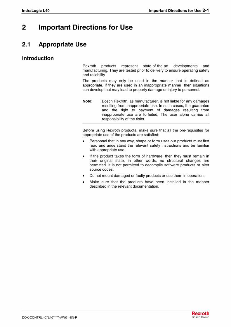
IntroductionRexroth products represent state-of-the-art developments andmanufacturing. They are tested prior to delivery to ensure operating safetyand reliability.
The products may only be used in the manner that is defined asappropriate. If they are used in an inappropriate manner, then situationscan develop that may lead to property damage or injury to personnel.
Note: Bosch Rexroth, as manufacturer, is not liable for any damagesresulting from inappropriate use. In such cases, the guaranteeand the right to payment of damages resulting frominappropriate use are forfeited. The user alone carries allresponsibility of the risks.
Before using Rexroth products, make sure that all the pre-requisites forappropriate use of the products are satisfied:
• Personnel that in any way, shape or form uses our products must firstread and understand the relevant safety instructions and be familiarwith appropriate use.
• If the product takes the form of hardware, then they must remain intheir original state, in other words, no structural changes arepermitted. It is not permitted to decompile software products or altersource codes.
• Do not mount damaged or faulty products or use them in operation.
• Make sure that the products have been installed in the mannerdescribed in the relevant documentation.
2-2 Important Directions for Use IndraLogic L40
DOK-CONTRL-IC*L40*****-AW01-EN-P
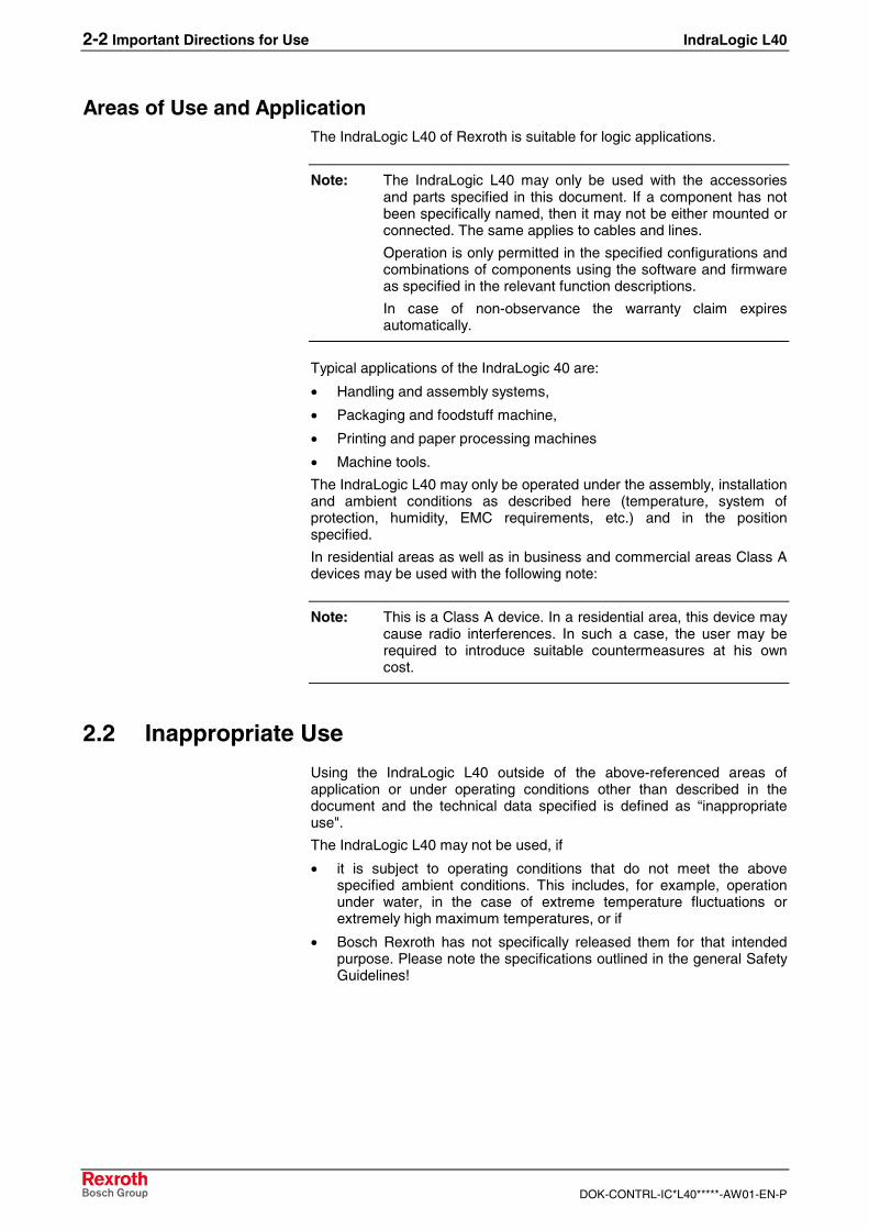
Areas of Use and ApplicationThe IndraLogic L40 of Rexroth is suitable for logic applications.
Note: The IndraLogic L40 may only be used with the accessoriesand parts specified in this document. If a component has notbeen specifically named, then it may not be either mounted orconnected. The same applies to cables and lines.
Operation is only permitted in the specified configurations andcombinations of components using the software and firmwareas specified in the relevant function descriptions.
In case of non-observance the warranty claim expiresautomatically.
Typical applications of the IndraLogic 40 are:
• Handling and assembly systems,
• Packaging and foodstuff machine,
• Printing and paper processing machines
• Machine tools.
The IndraLogic L40 may only be operated under the assembly, installationand ambient conditions as described here (temperature, system ofprotection, humidity, EMC requirements, etc.) and in the positionspecified.
In residential areas as well as in business and commercial areas Class Adevices may be used with the following note:
Note: This is a Class A device. In a residential area, this device maycause radio interferences. In such a case, the user may berequired to introduce suitable countermeasures at his owncost.
2.2 Inappropriate Use
Using the IndraLogic L40 outside of the above-referenced areas ofapplication or under operating conditions other than described in thedocument and the technical data specified is defined as “inappropriateuse".
The IndraLogic L40 may not be used, if
• it is subject to operating conditions that do not meet the abovespecified ambient conditions. This includes, for example, operationunder water, in the case of extreme temperature fluctuations orextremely high maximum temperatures, or if
• Bosch Rexroth has not specifically released them for that intendedpurpose. Please note the specifications outlined in the general SafetyGuidelines!
IndraLogic L40 Safety Instructions for Electric Drives and Controls 3-1
DOK-CONTRL-IC*L40*****-AW01-EN-P
3 Safety Instructions for Electric Drives and Controls
3.1 Introduction
Read these instructions before the initial startup of the equipment in orderto eliminate the risk of bodily harm or material damage. Follow thesesafety instructions at all times.
Do not attempt to install or start up this equipment without first reading alldocumentation provided with the product. Read and understand thesesafety instructions and all user documentation of the equipment prior toworking with the equipment at any time. If you do not have the userdocumentation for your equipment, contact your local Bosch Rexrothrepresentative to send this documentation immediately to the person orpersons responsible for the safe operation of this equipment.
If the equipment is resold, rented or transferred or passed on to others,then these safety instructions must be delivered with the equipment.
WARNING
Improper use of this equipment, failure to followthe safety instructions in this document ortampering with the product, including disablingof safety devices, may result in materialdamage, bodily harm, electric shock or evendeath!
3.2 Explanations
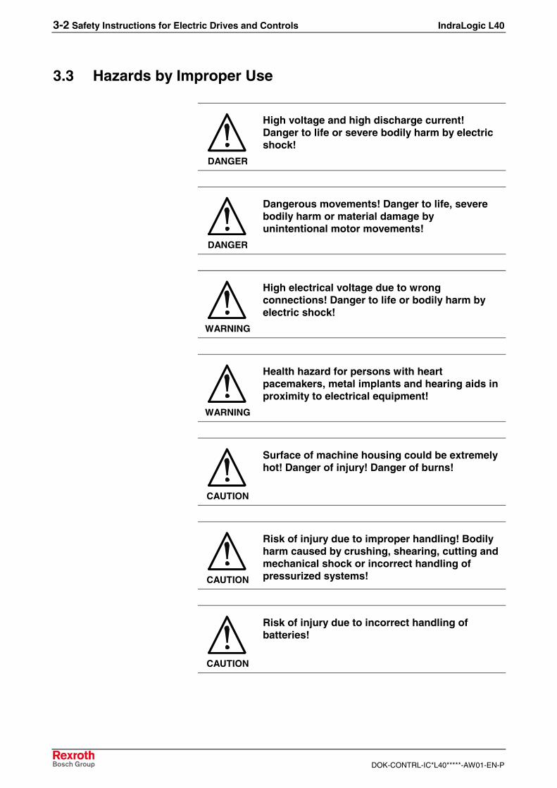
The safety instructions describe the following degrees of hazardseriousness in compliance with ANSI Z535. The degree of hazardseriousness informs about the consequences resulting from non-compliance with the safety instructions.
Warning symbol with signalword
Degree of hazard seriousness accordingto ANSI
DANGER
Death or severe bodily harm will occur.
WARNING
Death or severe bodily harm may occur.
CAUTION
Bodily harm or material damage may occur.
Fig. 3-1: Hazard classification (according to ANSI Z535)
3-2 Safety Instructions for Electric Drives and Controls IndraLogic L40
DOK-CONTRL-IC*L40*****-AW01-EN-P
3.3 Hazards by Improper Use
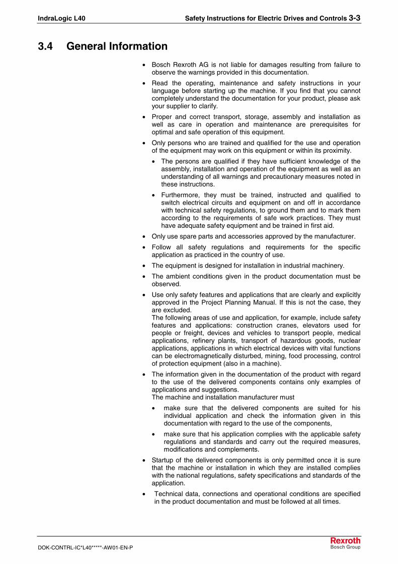
DANGER
High voltage and high discharge current!Danger to life or severe bodily harm by electricshock!
DANGER
Dangerous movements! Danger to life, severebodily harm or material damage byunintentional motor movements!
WARNING
High electrical voltage due to wrongconnections! Danger to life or bodily harm byelectric shock!
WARNING
Health hazard for persons with heartpacemakers, metal implants and hearing aids inproximity to electrical equipment!
CAUTION
Surface of machine housing could be extremelyhot! Danger of injury! Danger of burns!
CAUTION
Risk of injury due to improper handling! Bodilyharm caused by crushing, shearing, cutting andmechanical shock or incorrect handling ofpressurized systems!
CAUTION
Risk of injury due to incorrect handling ofbatteries!
IndraLogic L40 Safety Instructions for Electric Drives and Controls 3-3
DOK-CONTRL-IC*L40*****-AW01-EN-P
3.4 General Information
• Bosch Rexroth AG is not liable for damages resulting from failure toobserve the warnings provided in this documentation.
• Read the operating, maintenance and safety instructions in yourlanguage before starting up the machine. If you find that you cannotcompletely understand the documentation for your product, please askyour supplier to clarify.
• Proper and correct transport, storage, assembly and installation aswell as care in operation and maintenance are prerequisites foroptimal and safe operation of this equipment.
• Only persons who are trained and qualified for the use and operationof the equipment may work on this equipment or within its proximity.
• The persons are qualified if they have sufficient knowledge of theassembly, installation and operation of the equipment as well as anunderstanding of all warnings and precautionary measures noted inthese instructions.
• Furthermore, they must be trained, instructed and qualified toswitch electrical circuits and equipment on and off in accordancewith technical safety regulations, to ground them and to mark themaccording to the requirements of safe work practices. They musthave adequate safety equipment and be trained in first aid.
• Only use spare parts and accessories approved by the manufacturer.
• Follow all safety regulations and requirements for the specificapplication as practiced in the country of use.
• The equipment is designed for installation in industrial machinery.
• The ambient conditions given in the product documentation must beobserved.
• Use only safety features and applications that are clearly and explicitlyapproved in the Project Planning Manual. If this is not the case, theyare excluded.The following areas of use and application, for example, include safetyfeatures and applications: construction cranes, elevators used forpeople or freight, devices and vehicles to transport people, medicalapplications, refinery plants, transport of hazardous goods, nuclearapplications, applications in which electrical devices with vital functionscan be electromagnetically disturbed, mining, food processing, controlof protection equipment (also in a machine).
• The information given in the documentation of the product with regardto the use of the delivered components contains only examples ofapplications and suggestions.The machine and installation manufacturer must
• make sure that the delivered components are suited for hisindividual application and check the information given in thisdocumentation with regard to the use of the components,
• make sure that his application complies with the applicable safetyregulations and standards and carry out the required measures,modifications and complements.
• Startup of the delivered components is only permitted once it is surethat the machine or installation in which they are installed complieswith the national regulations, safety specifications and standards of theapplication.
• Technical data, connections and operational conditions are specifiedin the product documentation and must be followed at all times.
3-4 Safety Instructions for Electric Drives and Controls IndraLogic L40
DOK-CONTRL-IC*L40*****-AW01-EN-P
• Operation is only permitted if the national EMC regulations for theapplication are met.The instructions for installation in accordance with EMC requirementscan be found in the documentation "EMC in Drive and ControlSystems".The machine or installation manufacturer is responsible forcompliance with the limiting values as prescribed in the nationalregulations.
3.5 Protection Against Contact with Electrical Parts
Note: This section refers to equipment and drive components withvoltages above 50 Volts.
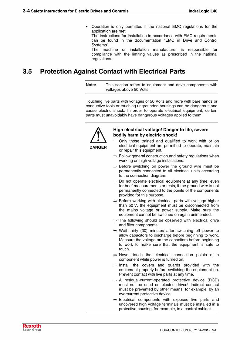
Touching live parts with voltages of 50 Volts and more with bare hands orconductive tools or touching ungrounded housings can be dangerous andcause electric shock. In order to operate electrical equipment, certainparts must unavoidably have dangerous voltages applied to them.
DANGER
High electrical voltage! Danger to life, severebodily harm by electric shock!⇒ Only those trained and qualified to work with or on
electrical equipment are permitted to operate, maintainor repair this equipment.
⇒ Follow general construction and safety regulations whenworking on high voltage installations.
⇒ Before switching on power the ground wire must bepermanently connected to all electrical units accordingto the connection diagram.
⇒ Do not operate electrical equipment at any time, evenfor brief measurements or tests, if the ground wire is notpermanently connected to the points of the componentsprovided for this purpose.
⇒ Before working with electrical parts with voltage higherthan 50 V, the equipment must be disconnected fromthe mains voltage or power supply. Make sure theequipment cannot be switched on again unintended.
⇒ The following should be observed with electrical driveand filter components:
⇒ Wait thirty (30) minutes after switching off power toallow capacitors to discharge before beginning to work.Measure the voltage on the capacitors before beginningto work to make sure that the equipment is safe totouch.
⇒ Never touch the electrical connection points of acomponent while power is turned on.
⇒ Install the covers and guards provided with theequipment properly before switching the equipment on.Prevent contact with live parts at any time.
⇒ A residual-current-operated protective device (RCD)must not be used on electric drives! Indirect contactmust be prevented by other means, for example, by anovercurrent protective device.
⇒ Electrical components with exposed live parts anduncovered high voltage terminals must be installed in aprotective housing, for example, in a control cabinet.
IndraLogic L40 Safety Instructions for Electric Drives and Controls 3-5
DOK-CONTRL-IC*L40*****-AW01-EN-P
To be observed with electrical drive and filter components:
DANGER
High electrical voltage on the housing!High leakage current! Danger to life, danger ofinjury by electric shock!⇒ Connect the electrical equipment, the housings of all
electrical units and motors permanently with the safetyconductor at the ground points before power isswitched on. Look at the connection diagram. This iseven necessary for brief tests.
⇒ Connect the safety conductor of the electricalequipment always permanently and firmly to thesupply mains. Leakage current exceeds 3.5 mA innormal operation.
⇒ Use a copper conductor with at least 10 mm² crosssection over its entire course for this safety conductorconnection!
⇒ Prior to startups, even for brief tests, always connectthe protective conductor or connect with ground wire.Otherwise, high voltages can occur on the housingthat lead to electric shock.
3.6 Protection Against Electric Shock by Protective LowVoltage (PELV)
All connections and terminals with voltages between 0 and 50 Volts onRexroth products are protective low voltages designed in accordance withinternational standards on electrical safety.
WARNING
High electrical voltage due to wrongconnections! Danger to life, bodily harm byelectric shock!⇒ Only connect equipment, electrical components and
cables of the protective low voltage type (PELV =Protective Extra Low Voltage) to all terminals andclamps with voltages of 0 to 50 Volts.
⇒ Only electrical circuits may be connected which aresafely isolated against high voltage circuits. Safeisolation is achieved, for example, with an isolatingtransformer, an opto-electronic coupler or whenbattery-operated.
3-6 Safety Instructions for Electric Drives and Controls IndraLogic L40
DOK-CONTRL-IC*L40*****-AW01-EN-P
3.7 Protection Against Dangerous Movements
Dangerous movements can be caused by faulty control of the connectedmotors. Some common examples are:
• improper or wrong wiring of cable connections
• incorrect operation of the equipment components
• wrong input of parameters before operation
• malfunction of sensors, encoders and monitoring devices
• defective components
• software or firmware errors
Dangerous movements can occur immediately after equipment isswitched on or even after an unspecified time of trouble-free operation.
The monitoring in the drive components will normally be sufficient to avoidfaulty operation in the connected drives. Regarding personal safety,especially the danger of bodily injury and material damage, this alonecannot be relied upon to ensure complete safety. Until the integratedmonitoring functions become effective, it must be assumed in any casethat faulty drive movements will occur. The extent of faulty drivemovements depends upon the type of control and the state of operation.
IndraLogic L40 Safety Instructions for Electric Drives and Controls 3-7
DOK-CONTRL-IC*L40*****-AW01-EN-P
DANGER
Dangerous movements! Danger to life, risk ofinjury, severe bodily harm or material damage!⇒ Ensure personal safety by means of qualified and
tested higher-level monitoring devices or measuresintegrated in the installation. Unintended machinemotion is possible if monitoring devices are disabled,bypassed or not activated.
⇒ Pay attention to unintended machine motion or othermalfunction in any mode of operation.
⇒ Keep free and clear of the machine’s range of motionand moving parts. Possible measures to preventpeople from accidentally entering the machine’s rangeof motion:
- use safety fences
- use safety guards
- use protective coverings
- install light curtains or light barriers
⇒ Fences and coverings must be strong enough toresist maximum possible momentum, especially ifthere is a possibility of loose parts flying off.
⇒ Mount the emergency stop switch in the immediatereach of the operator. Verify that the emergency stopworks before startup. Don’t operate the machine if theemergency stop is not working.
⇒ Isolate the drive power connection by means of anemergency stop circuit or use a starting lockout toprevent unintentional start.
⇒ Make sure that the drives are brought to a safestandstill before accessing or entering the dangerzone. Safe standstill can be achieved by switching offthe power supply contactor or by safe mechanicallocking of moving parts.
⇒ Secure vertical axes against falling or dropping afterswitching off the motor power by, for example:
- mechanically securing the vertical axes
- adding an external braking/ arrester/ clampingmechanism
- ensuring sufficient equilibration of the vertical axes
The standard equipment motor brake or an externalbrake controlled directly by the drive controller arenot sufficient to guarantee personal safety!
⇒ Disconnect electrical power to the equipment using amaster switch and secure the switch againstreconnection for:
- maintenance and repair work
- cleaning of equipment
- long periods of discontinued equipment use
⇒ Prevent the operation of high-frequency, remotecontrol and radio equipment near electronics circuitsand supply leads. If the use of such equipment cannotbe avoided, verify the system and the installation forpossible malfunctions in all possible positions ofnormal use before initial startup. If necessary, performa special electromagnetic compatibility (EMC) test onthe installation.
3-8 Safety Instructions for Electric Drives and Controls IndraLogic L40
DOK-CONTRL-IC*L40*****-AW01-EN-P
3.8 Protection Against Magnetic and Electromagnetic FieldsDuring Operation and Mounting
Magnetic and electromagnetic fields generated near current-carryingconductors and permanent magnets in motors represent a serious healthhazard to persons with heart pacemakers, metal implants and hearingaids.
WARNING
Health hazard for persons with heartpacemakers, metal implants and hearing aids inproximity to electrical equipment!⇒ Persons with heart pacemakers, hearing aids and
metal implants are not permitted to enter the followingareas:
- Areas in which electrical equipment and parts aremounted, being operated or started up.
- Areas in which parts of motors with permanentmagnets are being stored, operated, repaired ormounted.
⇒ If it is necessary for a person with a heart pacemakerto enter such an area, then a doctor must beconsulted prior to doing so. Heart pacemakers thatare already implanted or will be implanted in thefuture, have a considerable variation in their electricalnoise immunity. Therefore there are no rules withgeneral validity.
⇒ Persons with hearing aids, metal implants or metalpieces must consult a doctor before they enter theareas described above. Otherwise, health hazards willoccur.
IndraLogic L40 Safety Instructions for Electric Drives and Controls 3-9
DOK-CONTRL-IC*L40*****-AW01-EN-P
3.9 Protection Against Contact with Hot Parts
CAUTION
Housing surfaces could be extremely hot!Danger of injury! Danger of burns!⇒ Do not touch housing surfaces near sources of heat!
Danger of burns!⇒ After switching the equipment off, wait at least ten (10)
minutes to allow it to cool down before touching it.⇒ Do not touch hot parts of the equipment, such as
housings with integrated heat sinks and resistors.Danger of burns!
3.10 Protection During Handling and Mounting
Under certain conditions, incorrect handling and mounting of parts andcomponents may cause injuries.
CAUTION
Risk of injury by incorrect handling! Bodilyharm caused by crushing, shearing, cutting andmechanical shock!⇒ Observe general installation and safety instructions
with regard to handling and mounting.⇒ Use appropriate mounting and transport equipment.⇒ Take precautions to avoid pinching and crushing.⇒ Use only appropriate tools. If specified by the product
documentation, special tools must be used.⇒ Use lifting devices and tools correctly and safely.⇒ For safe protection wear appropriate protective
clothing, e.g. safety glasses, safety shoes and safetygloves.
⇒ Never stand under suspended loads.⇒ Clean up liquids from the floor immediately to prevent
slipping.
3-10 Safety Instructions for Electric Drives and Controls IndraLogic L40
DOK-CONTRL-IC*L40*****-AW01-EN-P
3.11 Battery Safety
Batteries contain reactive chemicals in a solid housing. Inappropriatehandling may result in injuries or material damage.
CAUTION
Risk of injury by incorrect handling!⇒ Do not attempt to reactivate discharged batteries by
heating or other methods (danger of explosion andcauterization).
⇒ Never charge non-chargeable batteries (danger ofleakage and explosion).
⇒ Never throw batteries into a fire.⇒ Do not dismantle batteries.⇒ Do not damage electrical components installed in the
equipment.
Note: Be aware of environmental protection and disposal! Thebatteries contained in the product should be considered ashazardous material for land, air and sea transport in the senseof the legal requirements (danger of explosion). Disposebatteries separately from other waste. Observe the legalrequirements in the country of installation.
3.12 Protection Against Pressurized Systems
Certain motors and drive controllers, corresponding to the information inthe respective Project Planning Manual, must be provided withpressurized media, such as compressed air, hydraulic oil, cooling fluidand cooling lubricant supplied by external systems. Incorrect handling ofthe supply and connections of pressurized systems can lead to injuries oraccidents. In these cases, improper handling of external supply systems,supply lines or connections can cause injuries or material damage.
CAUTION
Danger of injury by incorrect handling ofpressurized systems !⇒ Do not attempt to disassemble, to open or to cut a
pressurized system (danger of explosion).⇒ Observe the operation instructions of the respective
manufacturer.⇒ Before disassembling pressurized systems, release
pressure and drain off the fluid or gas.⇒ Use suitable protective clothing (for example safety
glasses, safety shoes and safety gloves)⇒ Remove any fluid that has leaked out onto the floor
immediately.
Note: Environmental protection and disposal! The media used in theoperation of the pressurized system equipment may not beenvironmentally compatible. Media that are damaging theenvironment must be disposed separately from normal waste.Observe the legal requirements in the country of installation.
IndraLogic L40 Projecting and Programming 4-1
DOK-CONTRL-IC*L40*****-AW01-EN-P
4 Projecting and Programming
4.1 Overview
To project an IndraLogic L40 the installation of "IndraWorks Logic" isrequired. The installation program is available on CD-ROM. During theinstallation also the required target information (Target Support Package)of the IndraLogic L40 are transferred to the target computer.
The project planning process is divided into the following steps:
• Project planning and I/O configuration with IndraWorks
• PLC program generation with IndraLogic
• Download and commissioning
• Operation, visualization and diagnosis with IndraWorks HMI andIndraWorks WinStudio, see /5/.
4.2 Projecting with IndraWorks
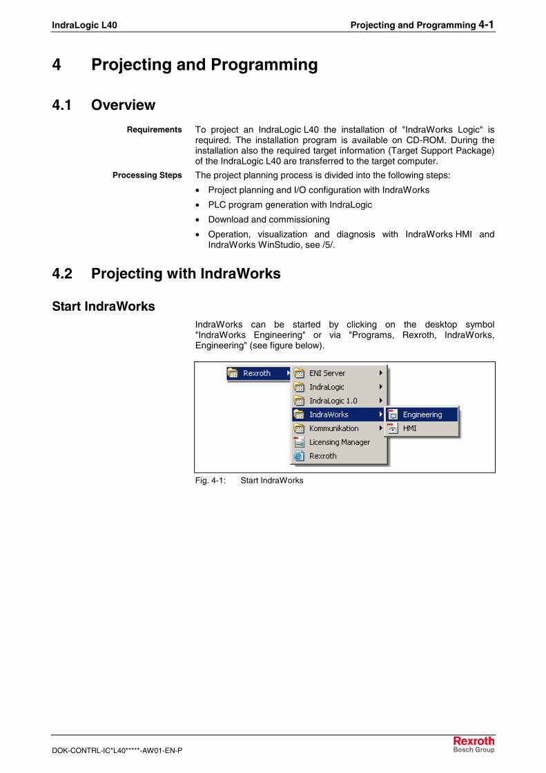
Start IndraWorksIndraWorks can be started by clicking on the desktop symbol"IndraWorks Engineering" or via "Programs, Rexroth, IndraWorks,Engineering" (see figure below).
Fig. 4-1: Start IndraWorks
Requirements
Processing Steps
4-2 Projecting and Programming IndraLogic L40
DOK-CONTRL-IC*L40*****-AW01-EN-P
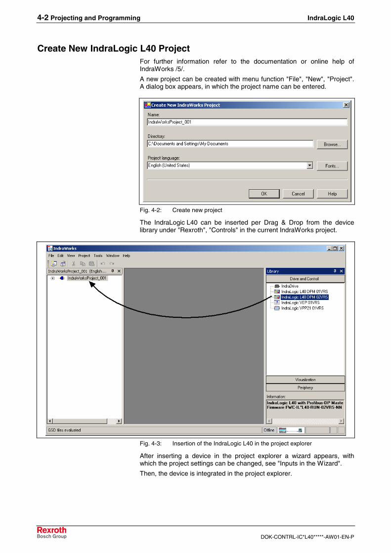
Create New IndraLogic L40 ProjectFor further information refer to the documentation or online help ofIndraWorks /5/.
A new project can be created with menu function "File", "New", "Project".A dialog box appears, in which the project name can be entered.
Fig. 4-2: Create new project
The IndraLogic L40 can be inserted per Drag & Drop from the devicelibrary under "Rexroth", "Controls" in the current IndraWorks project.
Fig. 4-3: Insertion of the IndraLogic L40 in the project explorer
After inserting a device in the project explorer a wizard appears, withwhich the project settings can be changed, see "Inputs in the Wizard".
Then, the device is integrated in the project explorer.
IndraLogic L40 Projecting and Programming 4-3
DOK-CONTRL-IC*L40*****-AW01-EN-P
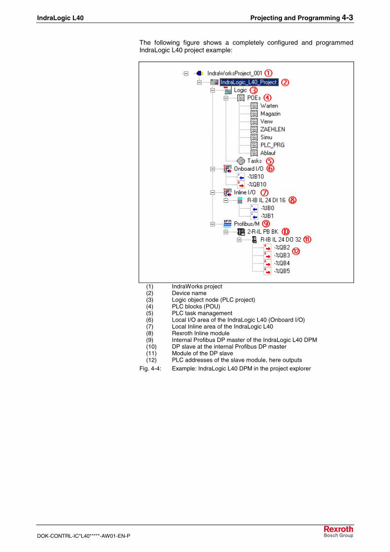
The following figure shows a completely configured and programmedIndraLogic L40 project example:
(1) IndraWorks project(2) Device name(3) Logic object node (PLC project)(4) PLC blocks (POU)(5) PLC task management(6) Local I/O area of the IndraLogic L40 (Onboard I/O)(7) Local Inline area of the IndraLogic L40(8) Rexroth Inline module(9) Internal Profibus DP master of the IndraLogic L40 DPM(10) DP slave at the internal Profibus DP master(11) Module of the DP slave(12) PLC addresses of the slave module, here outputs
Fig. 4-4: Example: IndraLogic L40 DPM in the project explorer
4-4 Projecting and Programming IndraLogic L40
DOK-CONTRL-IC*L40*****-AW01-EN-P
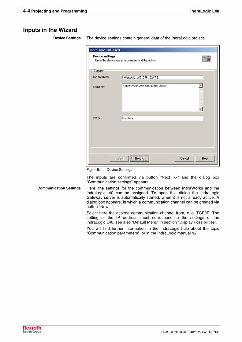
Inputs in the WizardThe device settings contain general data of the IndraLogic project.
Fig. 4-5: Device Settings
The inputs are confirmed via button "Next >>" and the dialog box"Communication settings" appears.
Here, the settings for the communication between IndraWorks and theIndraLogic L40 can be assigned. To open this dialog the IndraLogicGateway server is automatically started, when it is not already active. Adialog box appears, in which a communication channel can be created viabutton "New...".
Select here the desired communication channel from, e. g. TCP/IP. Thesetting of the IP address must correspond to the settings of theIndraLogic L40, see also "Default Menu" in section "Display Possibilities".
You will find further information in the IndraLogic help about the topic"Communication parameters", or in the IndraLogic manual /2/.
Device Settings
Communication Settings
IndraLogic L40 Projecting and Programming 4-5
DOK-CONTRL-IC*L40*****-AW01-EN-P
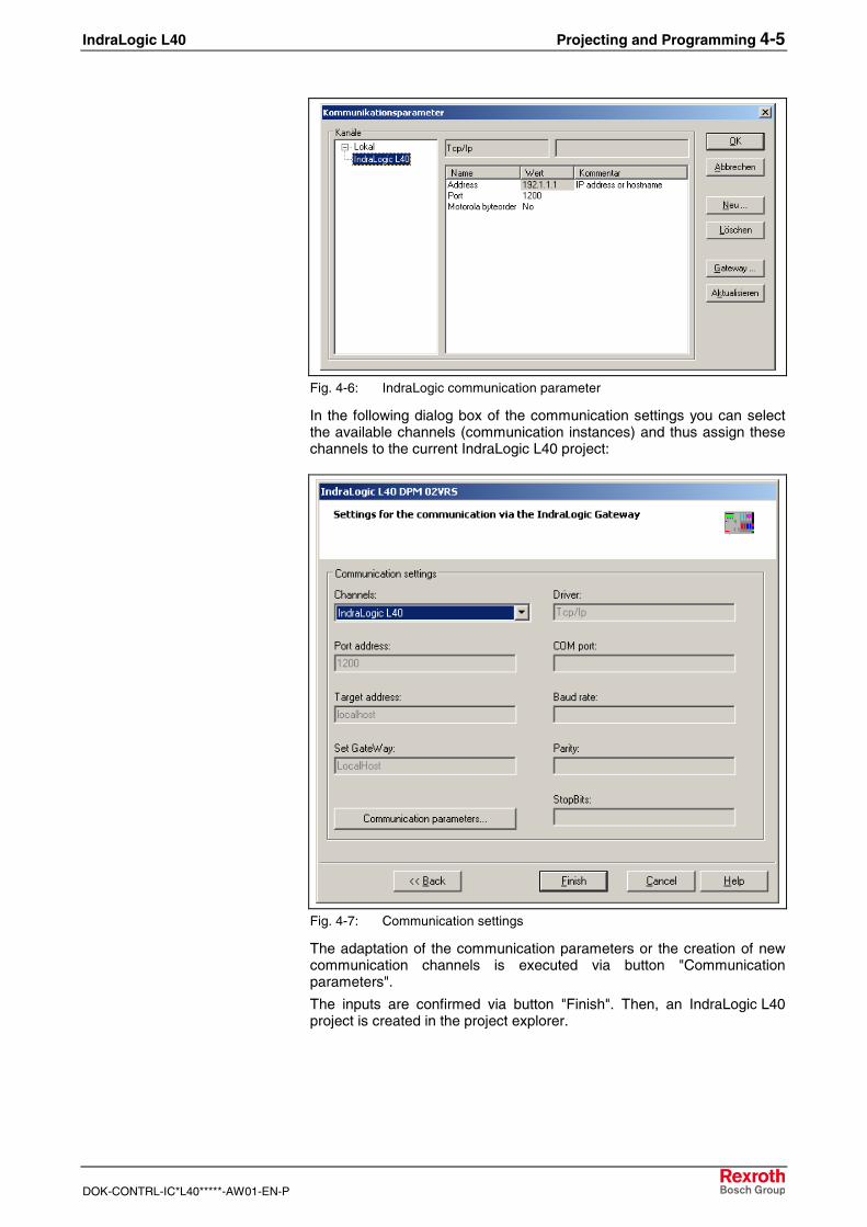
Fig. 4-6: IndraLogic communication parameter
In the following dialog box of the communication settings you can selectthe available channels (communication instances) and thus assign thesechannels to the current IndraLogic L40 project:
Fig. 4-7: Communication settings
The adaptation of the communication parameters or the creation of newcommunication channels is executed via button "Communicationparameters".
The inputs are confirmed via button "Finish". Then, an IndraLogic L40project is created in the project explorer.
4-6 Projecting and Programming IndraLogic L40
DOK-CONTRL-IC*L40*****-AW01-EN-P
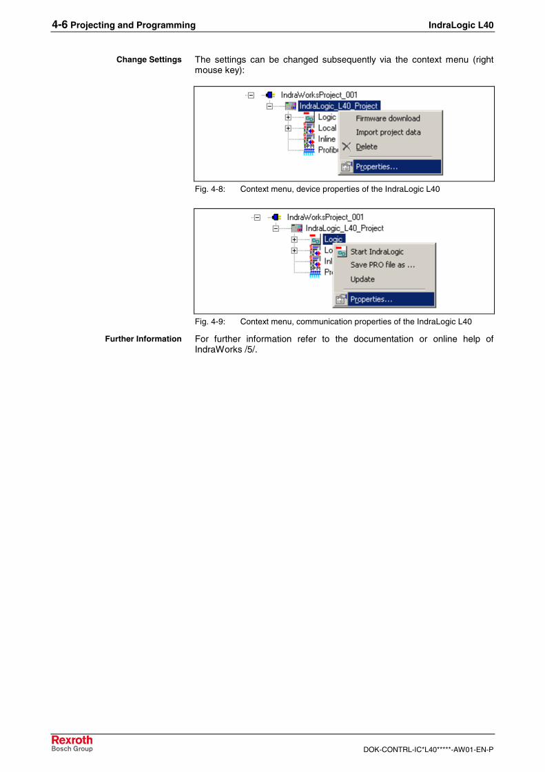
The settings can be changed subsequently via the context menu (rightmouse key):
Fig. 4-8: Context menu, device properties of the IndraLogic L40
Fig. 4-9: Context menu, communication properties of the IndraLogic L40
For further information refer to the documentation or online help ofIndraWorks /5/.
Change Settings
Further Information
IndraLogic L40 Projecting and Programming 4-7
DOK-CONTRL-IC*L40*****-AW01-EN-P
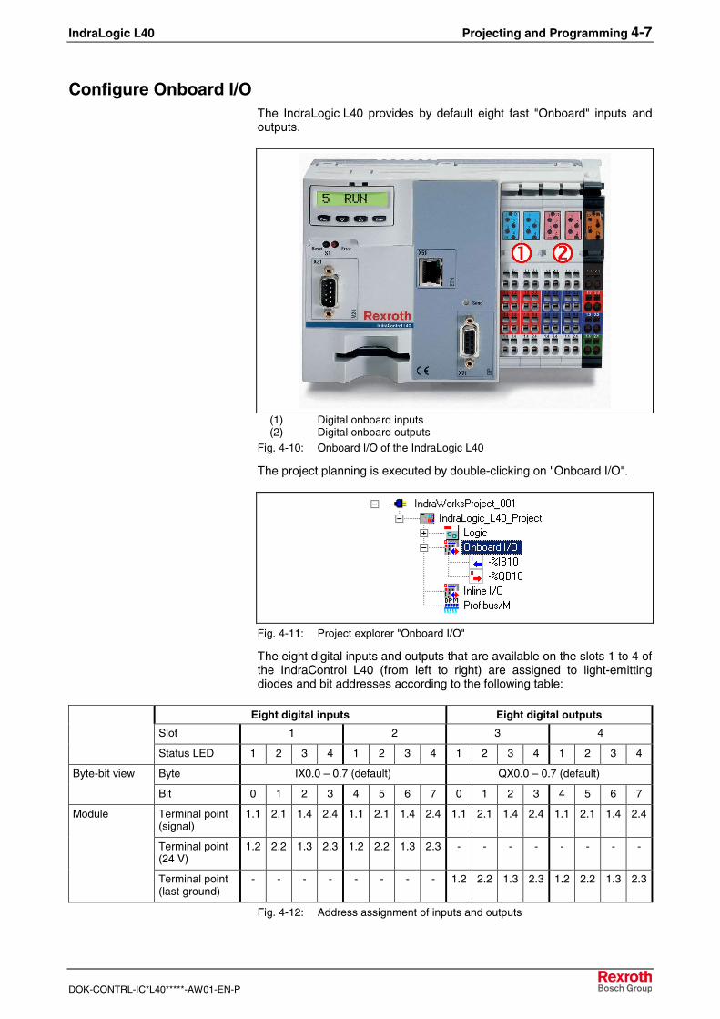
Configure Onboard I/OThe IndraLogic L40 provides by default eight fast "Onboard" inputs andoutputs.
(1) Digital onboard inputs(2) Digital onboard outputs
Fig. 4-10: Onboard I/O of the IndraLogic L40
The project planning is executed by double-clicking on "Onboard I/O".
Fig. 4-11: Project explorer "Onboard I/O"
The eight digital inputs and outputs that are available on the slots 1 to 4 ofthe IndraControl L40 (from left to right) are assigned to light-emittingdiodes and bit addresses according to the following table:
Eight digital inputs Eight digital outputs
Slot 1 2 3 4
Status LED 1 2 3 4 1 2 3 4 1 2 3 4 1 2 3 4
Byte IX0.0 – 0.7 (default) QX0.0 – 0.7 (default)Byte-bit view
Bit 0 1 2 3 4 5 6 7 0 1 2 3 4 5 6 7
Terminal point(signal)
1.1 2.1 1.4 2.4 1.1 2.1 1.4 2.4 1.1 2.1 1.4 2.4 1.1 2.1 1.4 2.4
Terminal point(24 V)
1.2 2.2 1.3 2.3 1.2 2.2 1.3 2.3 - - - - - - - -
Module
Terminal point(last ground)
- - - - - - - - 1.2 2.2 1.3 2.3 1.2 2.2 1.3 2.3
Fig. 4-12: Address assignment of inputs and outputs
4-8 Projecting and Programming IndraLogic L40
DOK-CONTRL-IC*L40*****-AW01-EN-P
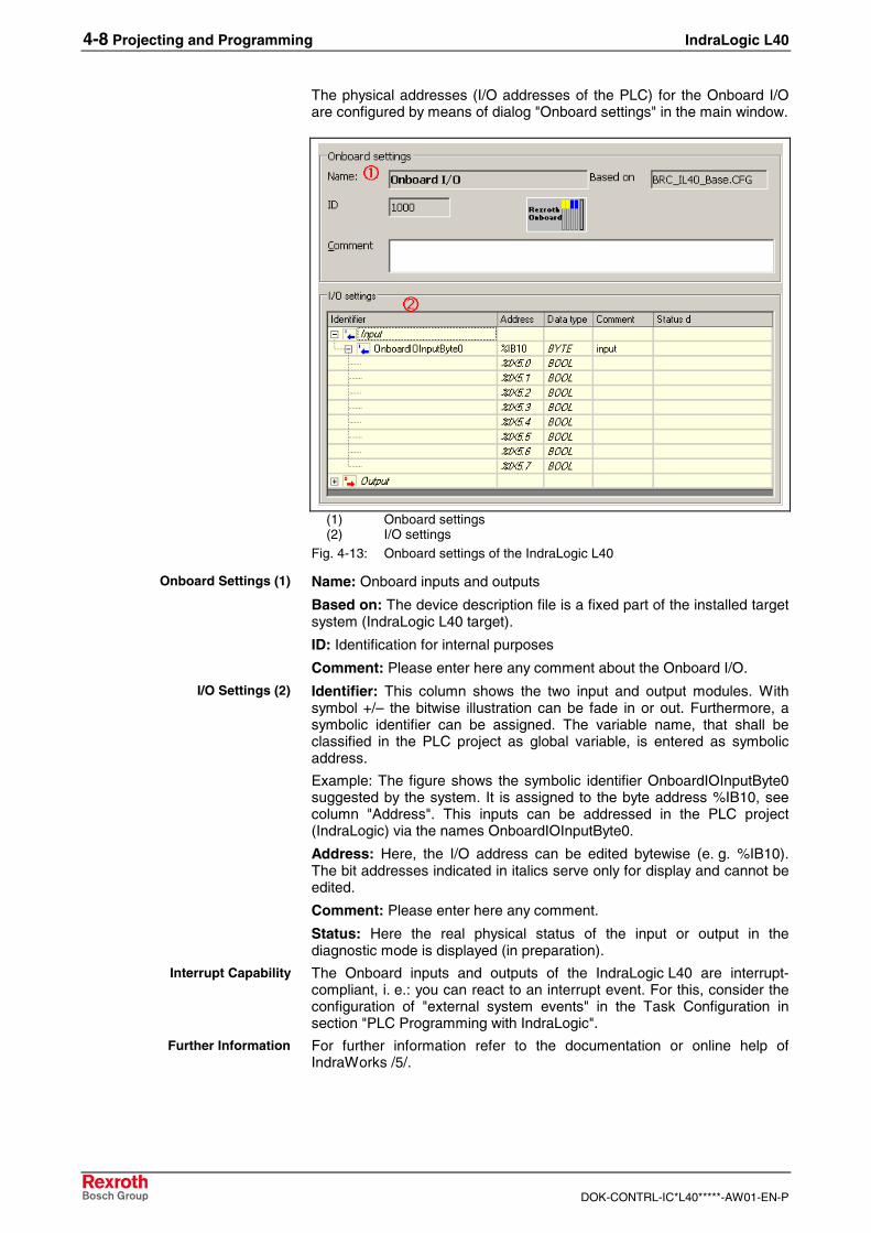
The physical addresses (I/O addresses of the PLC) for the Onboard I/Oare configured by means of dialog "Onboard settings" in the main window.
(1) Onboard settings(2) I/O settings
Fig. 4-13: Onboard settings of the IndraLogic L40
Name: Onboard inputs and outputs
Based on: The device description file is a fixed part of the installed targetsystem (IndraLogic L40 target).
ID: Identification for internal purposes
Comment: Please enter here any comment about the Onboard I/O.
Identifier: This column shows the two input and output modules. Withsymbol +/– the bitwise illustration can be fade in or out. Furthermore, asymbolic identifier can be assigned. The variable name, that shall beclassified in the PLC project as global variable, is entered as symbolicaddress.
Example: The figure shows the symbolic identifier OnboardIOInputByte0suggested by the system. It is assigned to the byte address %IB10, seecolumn "Address". This inputs can be addressed in the PLC project(IndraLogic) via the names OnboardIOInputByte0.
Address: Here, the I/O address can be edited bytewise (e. g. %IB10).The bit addresses indicated in italics serve only for display and cannot beedited.
Comment: Please enter here any comment.
Status: Here the real physical status of the input or output in thediagnostic mode is displayed (in preparation).
The Onboard inputs and outputs of the IndraLogic L40 are interrupt-compliant, i. e.: you can react to an interrupt event. For this, consider theconfiguration of "external system events" in the Task Configuration insection "PLC Programming with IndraLogic".
For further information refer to the documentation or online help ofIndraWorks /5/.
Onboard Settings (1)
I/O Settings (2)
Interrupt Capability
Further Information
IndraLogic L40 Projecting and Programming 4-9
DOK-CONTRL-IC*L40*****-AW01-EN-P
Projecting Inline ModulesThe locally available I/O units can be extended by the Rexroth Inline I/Osystem, just by simply mounting the components at the right side of theIndraLogic L40.
• Such modules permit extension of the local I/O unit to up to 32-byteinputs and 32-byte outputs.
• The maximum number of Rexroth Inline modules that can beconnected is 63.
• The modules can be connected in any order.
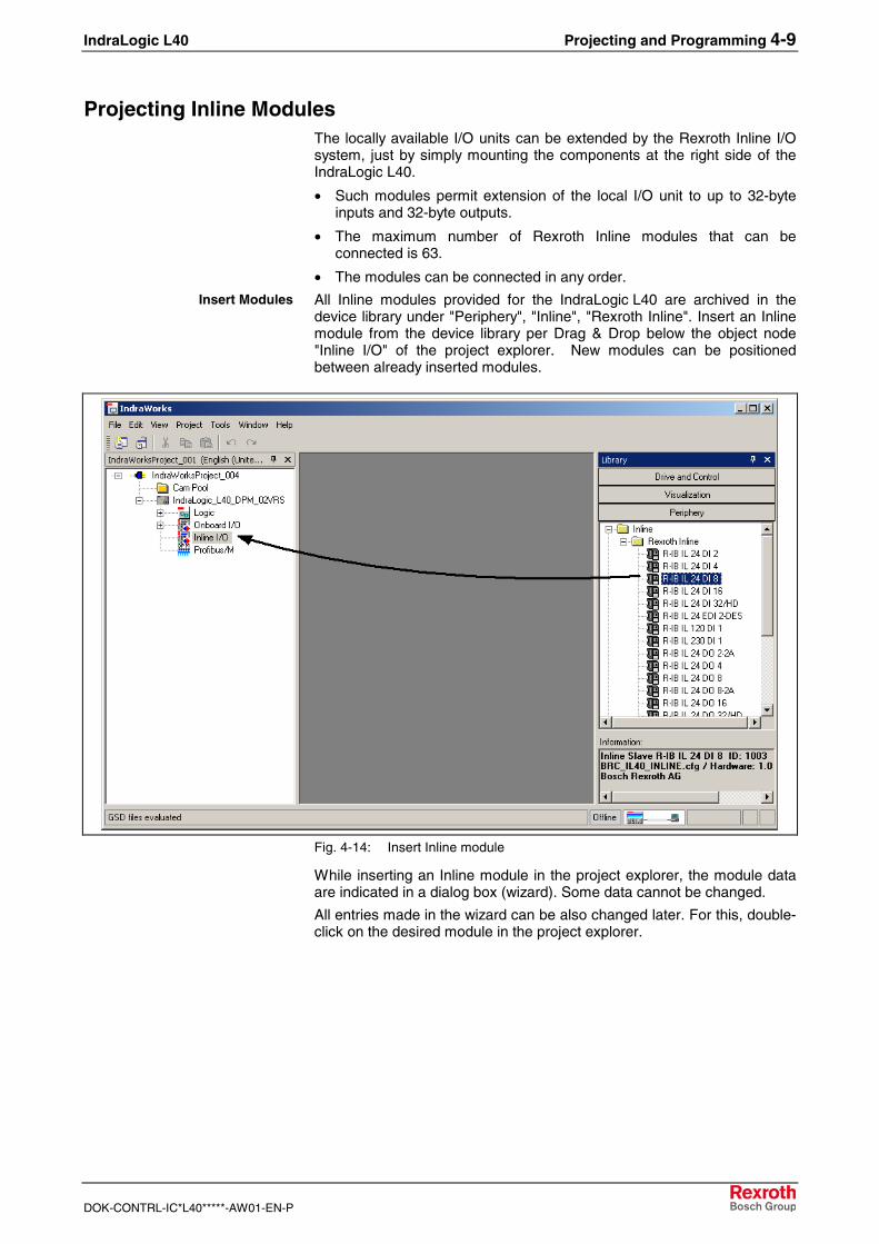
All Inline modules provided for the IndraLogic L40 are archived in thedevice library under "Periphery", "Inline", "Rexroth Inline". Insert an Inlinemodule from the device library per Drag & Drop below the object node"Inline I/O" of the project explorer. New modules can be positionedbetween already inserted modules.
Fig. 4-14: Insert Inline module
While inserting an Inline module in the project explorer, the module dataare indicated in a dialog box (wizard). Some data cannot be changed.
All entries made in the wizard can be also changed later. For this, double-click on the desired module in the project explorer.
Insert Modules
4-10 Projecting and Programming IndraLogic L40
DOK-CONTRL-IC*L40*****-AW01-EN-P
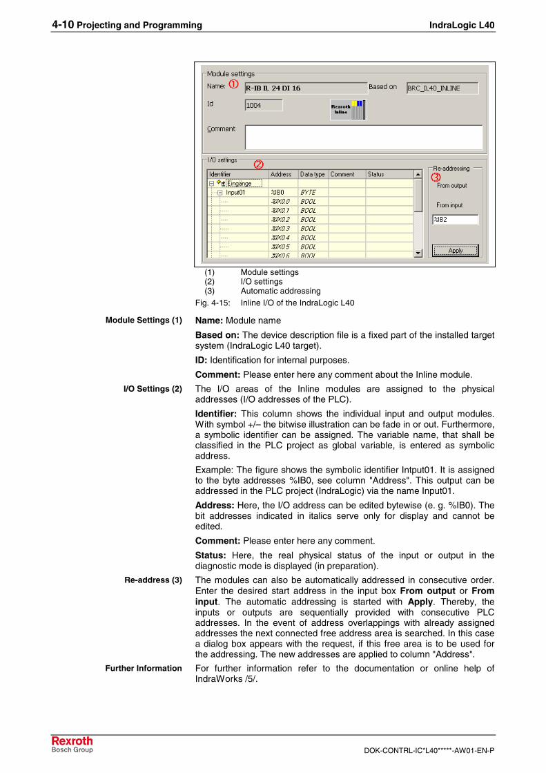
(1) Module settings(2) I/O settings(3) Automatic addressing
Fig. 4-15: Inline I/O of the IndraLogic L40
Name: Module name
Based on: The device description file is a fixed part of the installed targetsystem (IndraLogic L40 target).
ID: Identification for internal purposes.
Comment: Please enter here any comment about the Inline module.
The I/O areas of the Inline modules are assigned to the physicaladdresses (I/O addresses of the PLC).
Identifier: This column shows the individual input and output modules.With symbol +/– the bitwise illustration can be fade in or out. Furthermore,a symbolic identifier can be assigned. The variable name, that shall beclassified in the PLC project as global variable, is entered as symbolicaddress.
Example: The figure shows the symbolic identifier Intput01. It is assignedto the byte addresses %IB0, see column "Address". This output can beaddressed in the PLC project (IndraLogic) via the name Input01.
Address: Here, the I/O address can be edited bytewise (e. g. %IB0). Thebit addresses indicated in italics serve only for display and cannot beedited.
Comment: Please enter here any comment.
Status: Here, the real physical status of the input or output in thediagnostic mode is displayed (in preparation).
The modules can also be automatically addressed in consecutive order.Enter the desired start address in the input box From output or Frominput. The automatic addressing is started with Apply. Thereby, theinputs or outputs are sequentially provided with consecutive PLCaddresses. In the event of address overlappings with already assignedaddresses the next connected free address area is searched. In this casea dialog box appears with the request, if this free area is to be used forthe addressing. The new addresses are applied to column "Address".
For further information refer to the documentation or online help ofIndraWorks /5/.
Module Settings (1)
I/O Settings (2)
Re-address (3)
Further Information
IndraLogic L40 Projecting and Programming 4-11
DOK-CONTRL-IC*L40*****-AW01-EN-P
Configuring Profibus DPThe IndraLogic L40 DPM provides a PROFIBUS DP interface with busmaster functionality according to DIN EN 50170, Part 2. The Profibusconfiguration provides the following features
• Slave configuration
• Processing of vendor-specific data
• Modifying bus-specific settings
After finishing the Profibus configuration the data are transferred to thetarget device with the help of IndraLogic.
Note: Modified settings are only activated with the next download inthe PLC, see section "Download and Commissioning"!
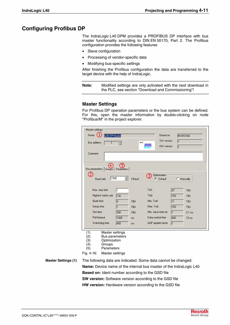
Master SettingsFor Profibus DP operation parameters or the bus system can be defined.For this, open the master information by double-clicking on node"Profibus/M" in the project explorer.
(1) Master settings(2) Bus parameters(3) Optimization(4) Groups(5) Parameters
Fig. 4-16: Master settings
The following data are indicated. Some data cannot be changed:
Name: Device name of the internal bus master of the IndraLogic L40
Based on: Ident number according to the GSD file
SW version: Software version according to the GSD file
HW version: Hardware version according to the GSD file
Master Settings (1)
4-12 Projecting and Programming IndraLogic L40
DOK-CONTRL-IC*L40*****-AW01-EN-P
Bus address: Here, bus address 1 (FDL address) is automaticallyentered. The address can be overwritten or modified by means of key"...". Address 0 is reserved for engineering devices and cannot be usedhere.
Note: Always use for the master bus addresses being as low aspossible, as for high bus addresses the bus performance(concerning the token ring management) deteriorates.
Comment: Please enter here any comment about the master.
The bus parameters important for the operation of the Profibus DP areindicated here. If the Optimization (3) is set to Default, only the boxes"Baud rate" and "Max. retry limit" can be edited. All other parameters aredefault values, that are optimized to the current baud rate. These defaultvalues correspond to a recommendation of the Profibus user organizationand is suitable for the majority of the applications. Only for specialexceptional cases it is necessary to modify a few parameters manually.For this, activate the Optimization: Manually (in preparation).
CAUTION
Modifications of the default bus parameters cancause an unpredictable behavior of theProfibus DP!⇒ The bus parameters may only be modified by
instructed Profibus DP specialists, who are aware ofthe effects of this modifications!
With groups sync and freeze commands of the master can be assigned tocertain slave groups.
Here, vendor-specific parameters of the master can be displayed oredited.
The parameter "EnableDiags" of the IndraLogic L40 has no function.
Note: Modified settings are only activated in the PLC with the nextdownload, see section "Download and Commissioning"!
For further information refer to the documentation or online help ofIndraWorks /5/.
Bus Parameters (2)(3)
Groups (4)
Parameters (5)
Further Information
IndraLogic L40 Projecting and Programming 4-13
DOK-CONTRL-IC*L40*****-AW01-EN-P
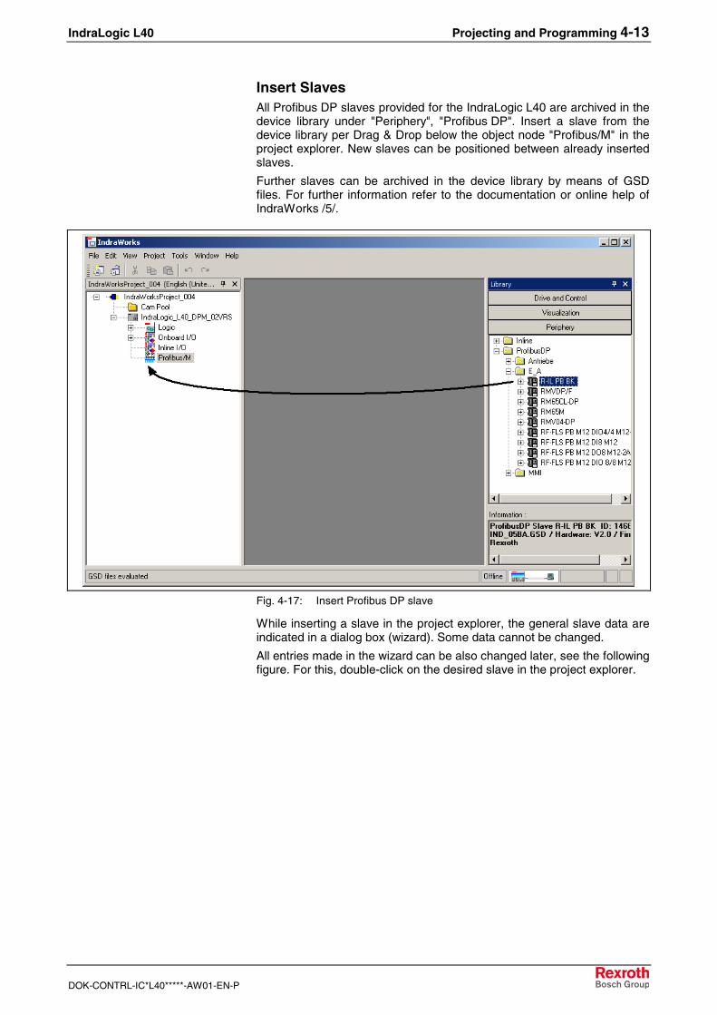
Insert SlavesAll Profibus DP slaves provided for the IndraLogic L40 are archived in thedevice library under "Periphery", "Profibus DP". Insert a slave from thedevice library per Drag & Drop below the object node "Profibus/M" in theproject explorer. New slaves can be positioned between already insertedslaves.
Further slaves can be archived in the device library by means of GSDfiles. For further information refer to the documentation or online help ofIndraWorks /5/.
Fig. 4-17: Insert Profibus DP slave
While inserting a slave in the project explorer, the general slave data areindicated in a dialog box (wizard). Some data cannot be changed.
All entries made in the wizard can be also changed later, see the followingfigure. For this, double-click on the desired slave in the project explorer.
4-14 Projecting and Programming IndraLogic L40
DOK-CONTRL-IC*L40*****-AW01-EN-P
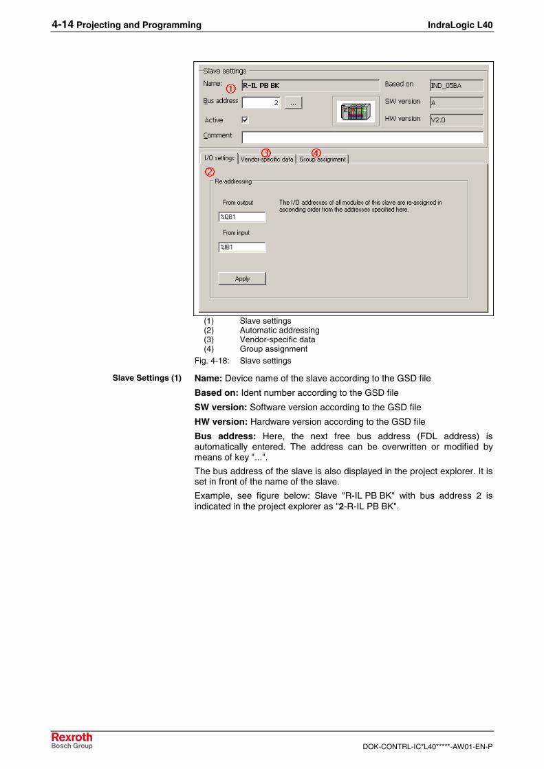
(1) Slave settings(2) Automatic addressing(3) Vendor-specific data(4) Group assignment
Fig. 4-18: Slave settings
Name: Device name of the slave according to the GSD file
Based on: Ident number according to the GSD file
SW version: Software version according to the GSD file
HW version: Hardware version according to the GSD file
Bus address: Here, the next free bus address (FDL address) isautomatically entered. The address can be overwritten or modified bymeans of key "...".
The bus address of the slave is also displayed in the project explorer. It isset in front of the name of the slave.
Example, see figure below: Slave "R-IL PB BK" with bus address 2 isindicated in the project explorer as "2-R-IL PB BK".
Slave Settings (1)
IndraLogic L40 Projecting and Programming 4-15
DOK-CONTRL-IC*L40*****-AW01-EN-P
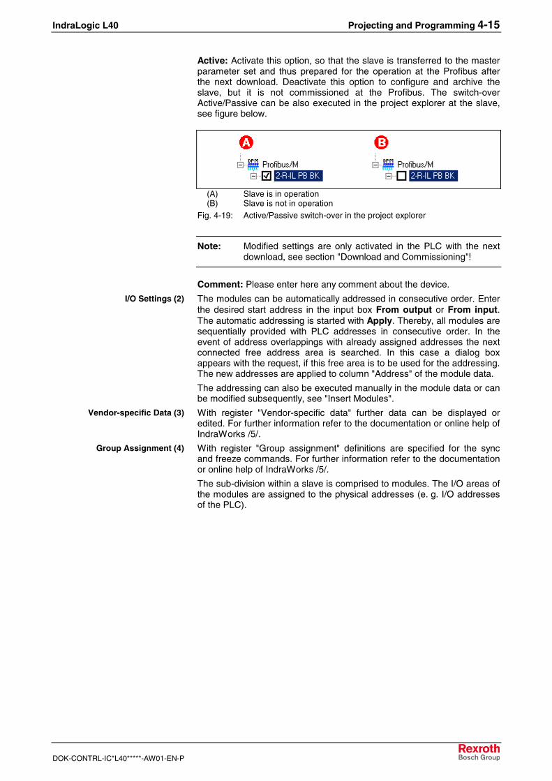
Active: Activate this option, so that the slave is transferred to the masterparameter set and thus prepared for the operation at the Profibus afterthe next download. Deactivate this option to configure and archive theslave, but it is not commissioned at the Profibus. The switch-overActive/Passive can be also executed in the project explorer at the slave,see figure below.
(A) Slave is in operation(B) Slave is not in operation
Fig. 4-19: Active/Passive switch-over in the project explorer
Note: Modified settings are only activated in the PLC with the nextdownload, see section "Download and Commissioning"!
Comment: Please enter here any comment about the device.
The modules can be automatically addressed in consecutive order. Enterthe desired start address in the input box From output or From input.The automatic addressing is started with Apply. Thereby, all modules aresequentially provided with PLC addresses in consecutive order. In theevent of address overlappings with already assigned addresses the nextconnected free address area is searched. In this case a dialog boxappears with the request, if this free area is to be used for the addressing.The new addresses are applied to column "Address" of the module data.
The addressing can also be executed manually in the module data or canbe modified subsequently, see "Insert Modules".
With register "Vendor-specific data" further data can be displayed oredited. For further information refer to the documentation or online help ofIndraWorks /5/.
With register "Group assignment" definitions are specified for the syncand freeze commands. For further information refer to the documentationor online help of IndraWorks /5/.
The sub-division within a slave is comprised to modules. The I/O areas ofthe modules are assigned to the physical addresses (e. g. I/O addressesof the PLC).
I/O Settings (2)
Vendor-specific Data (3)
Group Assignment (4)
4-16 Projecting and Programming IndraLogic L40
DOK-CONTRL-IC*L40*****-AW01-EN-P
Insert ModulesProfibus DP distinguishes between two slave types:
• Compact: A compact slave has a firmly defined module structure.
• Modular: However, for a modular slave the modules can beindividually assigned depending on the fitting specification.
After inserting a slave in the project explorer (see "Insert Slaves") themodules below the slave object node are already completely available formodules in compact design. However, for modular slaves the moduleshave to be manually assigned.
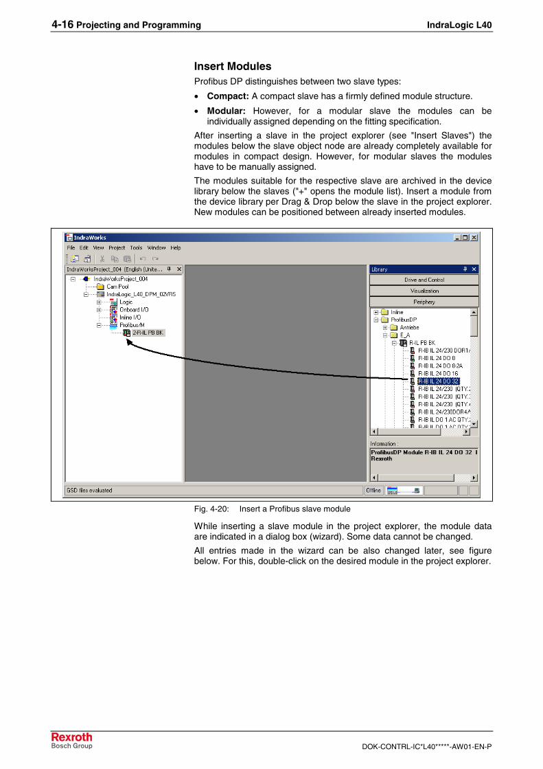
The modules suitable for the respective slave are archived in the devicelibrary below the slaves ("+" opens the module list). Insert a module fromthe device library per Drag & Drop below the slave in the project explorer.New modules can be positioned between already inserted modules.
Fig. 4-20: Insert a Profibus slave module
While inserting a slave module in the project explorer, the module dataare indicated in a dialog box (wizard). Some data cannot be changed.
All entries made in the wizard can be also changed later, see figurebelow. For this, double-click on the desired module in the project explorer.
IndraLogic L40 Projecting and Programming 4-17
DOK-CONTRL-IC*L40*****-AW01-EN-P
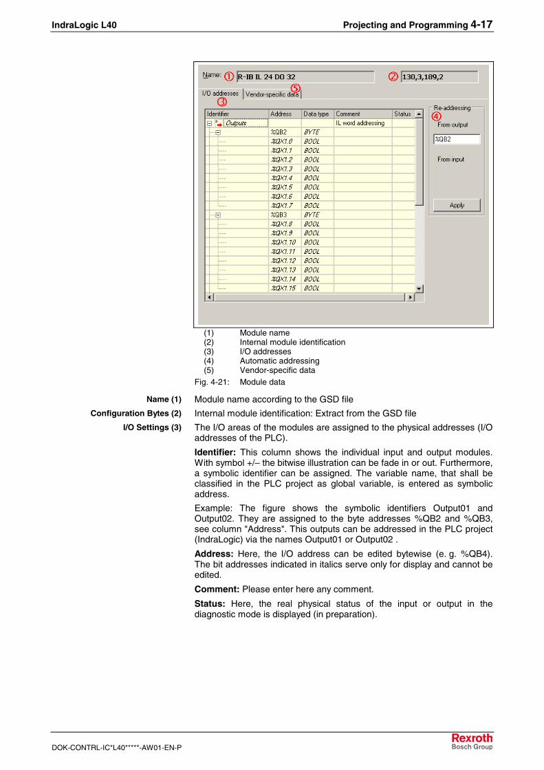
(1) Module name(2) Internal module identification(3) I/O addresses(4) Automatic addressing(5) Vendor-specific data
Fig. 4-21: Module data
Module name according to the GSD file
Internal module identification: Extract from the GSD file
The I/O areas of the modules are assigned to the physical addresses (I/Oaddresses of the PLC).
Identifier: This column shows the individual input and output modules.With symbol +/– the bitwise illustration can be fade in or out. Furthermore,a symbolic identifier can be assigned. The variable name, that shall beclassified in the PLC project as global variable, is entered as symbolicaddress.
Example: The figure shows the symbolic identifiers Output01 andOutput02. They are assigned to the byte addresses %QB2 and %QB3,see column "Address". This outputs can be addressed in the PLC project(IndraLogic) via the names Output01 or Output02 .
Address: Here, the I/O address can be edited bytewise (e. g. %QB4).The bit addresses indicated in italics serve only for display and cannot beedited.
Comment: Please enter here any comment.
Status: Here, the real physical status of the input or output in thediagnostic mode is displayed (in preparation).
Name (1)
Configuration Bytes (2)
I/O Settings (3)
4-18 Projecting and Programming IndraLogic L40
DOK-CONTRL-IC*L40*****-AW01-EN-P
The modules can also be automatically addressed in consecutive order.Enter the desired start address in the input box From output or Frominput. The automatic addressing is started with Apply. Thereby, allmodules are sequentially provided with PLC addresses in consecutiveorder. In the event of address overlappings with already assignedaddresses the next connected free address area is searched. In this casea dialog box appears with the request, if this free area is to be used forthe addressing. The new addresses are applied to column "Address".
With register "Vendor-specific data" further data can be displayed oredited. For further information refer to the documentation or online help ofIndraWorks /5/.
Sync and Freeze FunctionsAs of version 02VRS, the IndraLogic L40 supports the Sync and Freezefunction of Profibus DP. Using the Sync function, e. g. the outputs ofseveral drives (e. g. Rexroth EcoDrive) can be synchronized.
To be able to execute the sync and freeze functions with theIndraLogic L40, function block DP_SYCFR in library RIL_ProfibusDP isprovided, see corresponding section.
When using Sync or Freeze in the project explorer, an assignment of thegroups at the master and the corresponding slaves must be set. Forfurther information refer to the documentation or online help ofIndraWorks /5/.
Re-addressing (4)
Vendor-specific Data (5)
IndraLogic L40 Projecting and Programming 4-19
DOK-CONTRL-IC*L40*****-AW01-EN-P
4.3 PLC Programming with IndraLogic
OverviewFor the PLC project planning the following functions can be executed viathe program integrated in IndraWorks:
• Target Settings: Settings of the IndraLogic L40
• Task Configuration: Control of the program execution
• PLC Configuration: The PLC configuration is not generated withinIndraLogic, but in IndraWorks.
• Library Manager: Manage PLC block libraries
• Create a PLC Program: Create blocks in PLC programminglanguages.
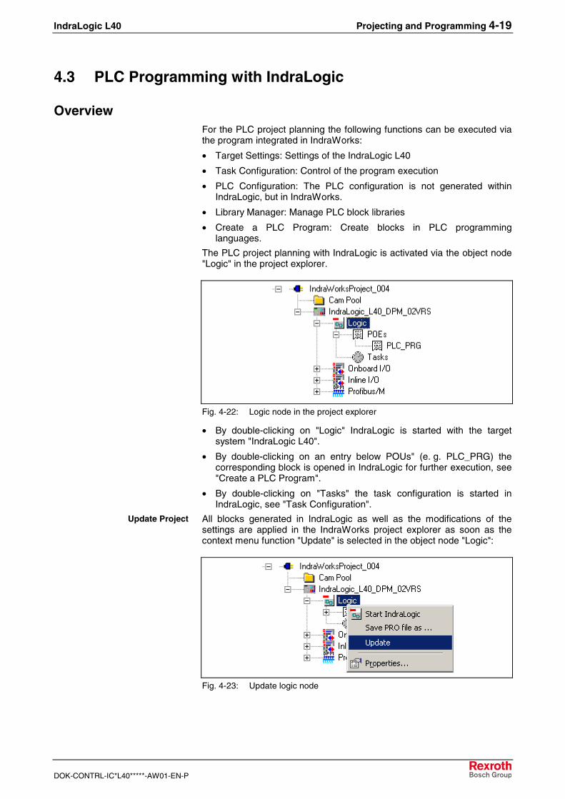
The PLC project planning with IndraLogic is activated via the object node"Logic" in the project explorer.
Fig. 4-22: Logic node in the project explorer
• By double-clicking on "Logic" IndraLogic is started with the targetsystem "IndraLogic L40".
• By double-clicking on an entry below POUs" (e. g. PLC_PRG) thecorresponding block is opened in IndraLogic for further execution, see"Create a PLC Program".
• By double-clicking on "Tasks" the task configuration is started inIndraLogic, see "Task Configuration".
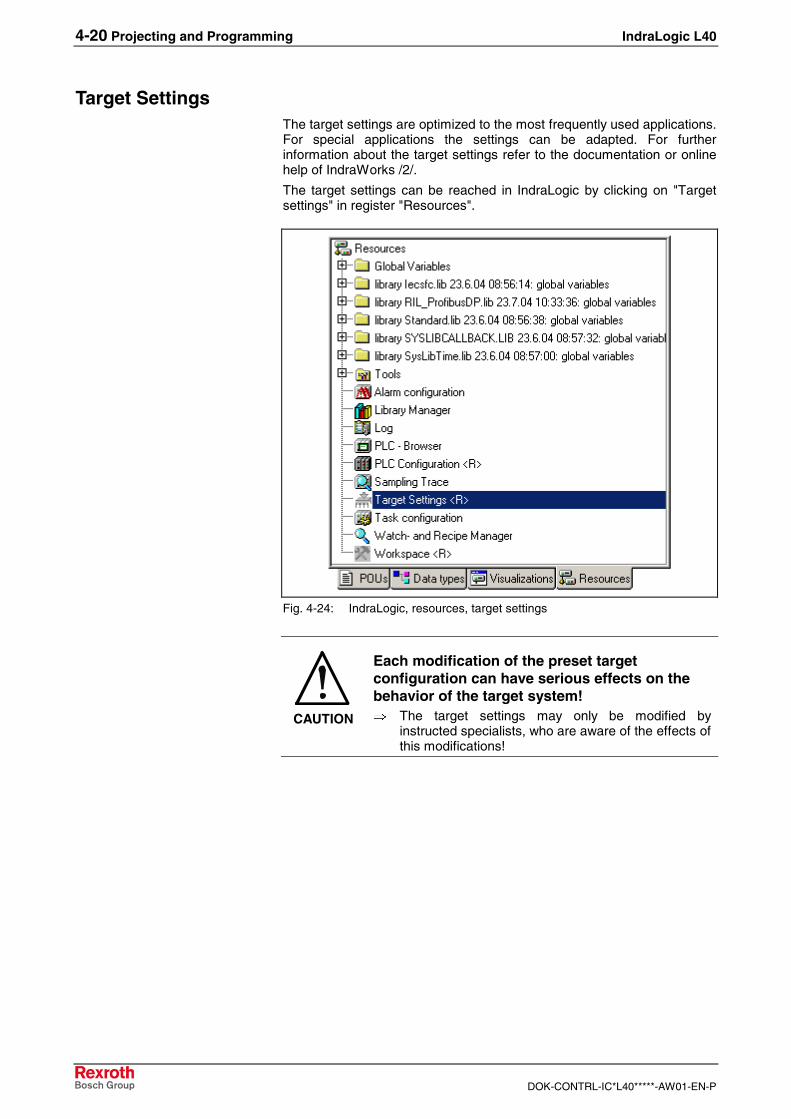
All blocks generated in IndraLogic as well as the modifications of thesettings are applied in the IndraWorks project explorer as soon as thecontext menu function "Update" is selected in the object node "Logic":
Fig. 4-23: Update logic node
Update Project
4-20 Projecting and Programming IndraLogic L40
DOK-CONTRL-IC*L40*****-AW01-EN-P
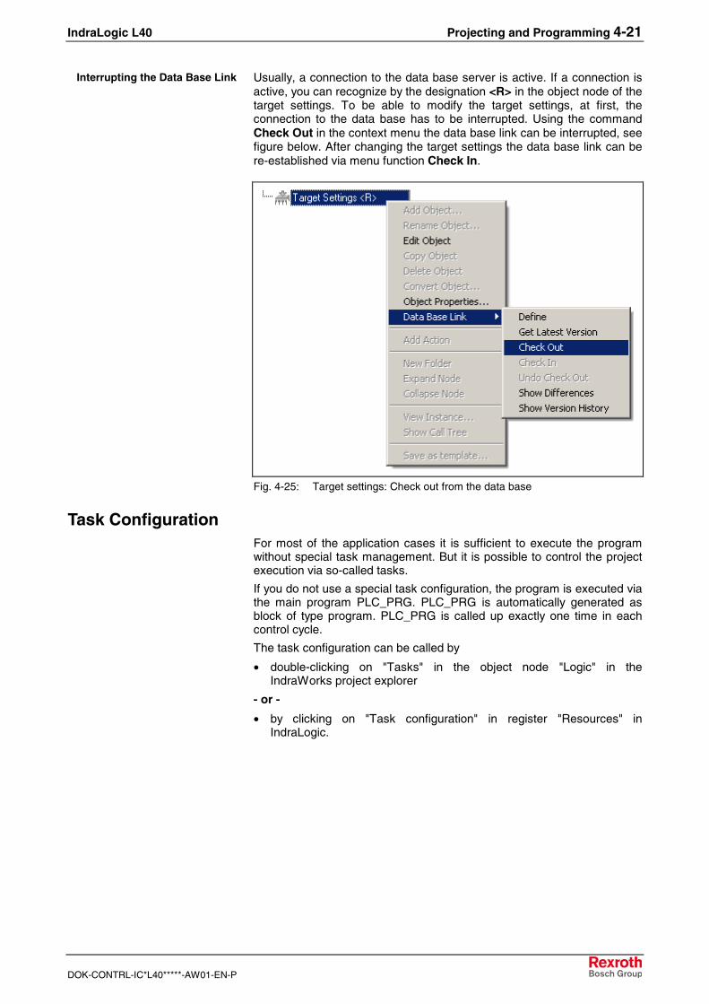
Target SettingsThe target settings are optimized to the most frequently used applications.For special applications the settings can be adapted. For furtherinformation about the target settings refer to the documentation or onlinehelp of IndraWorks /2/.
The target settings can be reached in IndraLogic by clicking on "Targetsettings" in register "Resources".
Fig. 4-24: IndraLogic, resources, target settings
CAUTION
Each modification of the preset targetconfiguration can have serious effects on thebehavior of the target system!⇒ The target settings may only be modified by
instructed specialists, who are aware of the effects ofthis modifications!
IndraLogic L40 Projecting and Programming 4-21
DOK-CONTRL-IC*L40*****-AW01-EN-P
Usually, a connection to the data base server is active. If a connection isactive, you can recognize by the designation <R> in the object node of thetarget settings. To be able to modify the target settings, at first, theconnection to the data base has to be interrupted. Using the commandCheck Out in the context menu the data base link can be interrupted, seefigure below. After changing the target settings the data base link can bere-established via menu function Check In.
Fig. 4-25: Target settings: Check out from the data base
Task ConfigurationFor most of the application cases it is sufficient to execute the programwithout special task management. But it is possible to control the projectexecution via so-called tasks.
If you do not use a special task configuration, the program is executed viathe main program PLC_PRG. PLC_PRG is automatically generated asblock of type program. PLC_PRG is called up exactly one time in eachcontrol cycle.
The task configuration can be called by
• double-clicking on "Tasks" in the object node "Logic" in theIndraWorks project explorer
- or -
• by clicking on "Task configuration" in register "Resources" inIndraLogic.
Interrupting the Data Base Link
4-22 Projecting and Programming IndraLogic L40
DOK-CONTRL-IC*L40*****-AW01-EN-P
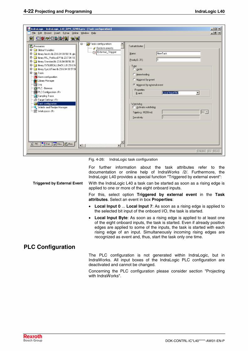
Fig. 4-26: IndraLogic task configuration
For further information about the task attributes refer to thedocumentation or online help of IndraWorks /2/. Furthermore, theIndraLogic L40 provides a special function "Triggered by external event":
With the IndraLogic L40 a task can be started as soon as a rising edge isapplied to one or more of the eight onboard inputs.
For this, select option Triggered by external event in the Taskattributes. Select an event in box Properties:
• Local Input 0 ... Local Input 7: As soon as a rising edge is applied tothe selected bit input of the onboard I/O, the task is started.
• Local Input Byte: As soon as a rising edge is applied to at least oneof the eight onboard inputs, the task is started. Even if already positiveedges are applied to some of the inputs, the task is started with eachrising edge of an input. Simultaneously incoming rising edges arerecognized as event and, thus, start the task only one time.
PLC ConfigurationThe PLC configuration is not generated within IndraLogic, but inIndraWorks. All input boxes of the IndraLogic PLC configuration aredeactivated and cannot be changed.
Concerning the PLC configuration please consider section "Projectingwith IndraWorks".
Triggered by External Event
IndraLogic L40 Projecting and Programming 4-23
DOK-CONTRL-IC*L40*****-AW01-EN-P
Library ManagerFor further information about the library manager refer to thedocumentation or online help of IndraWorks /2/.
For information about the libraries of the IndraLogic L40 refer to section"Libraries".
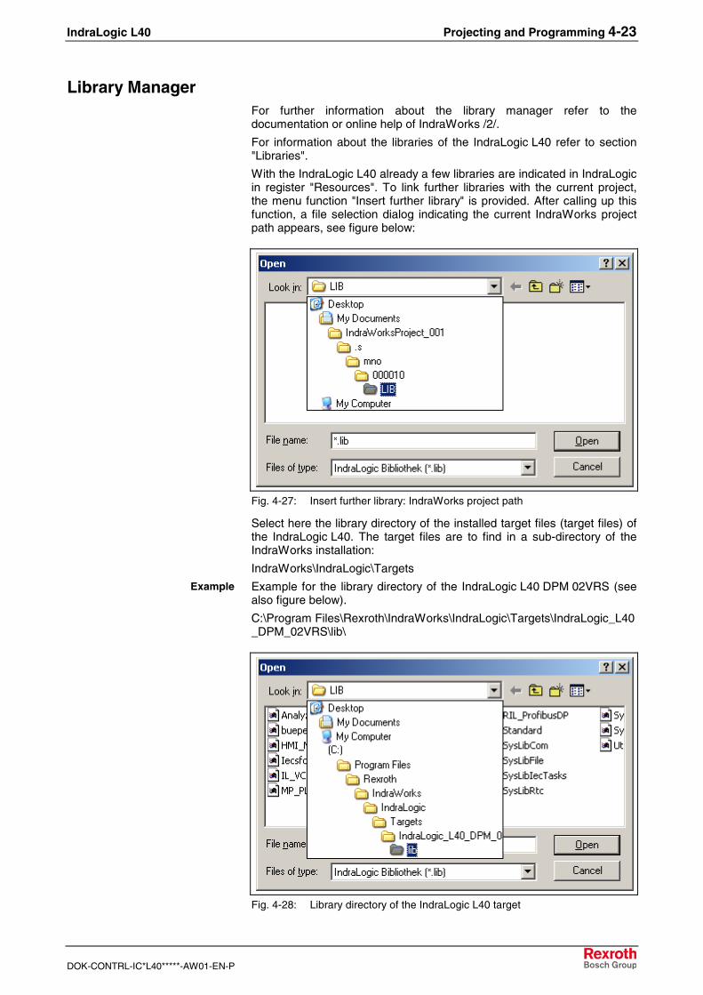
With the IndraLogic L40 already a few libraries are indicated in IndraLogicin register "Resources". To link further libraries with the current project,the menu function "Insert further library" is provided. After calling up thisfunction, a file selection dialog indicating the current IndraWorks projectpath appears, see figure below:
Fig. 4-27: Insert further library: IndraWorks project path
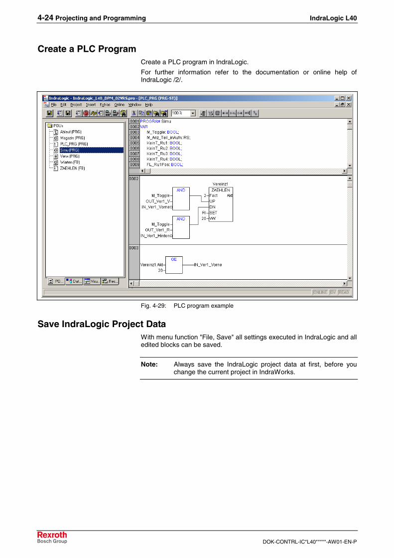
Select here the library directory of the installed target files (target files) ofthe IndraLogic L40. The target files are to find in a sub-directory of theIndraWorks installation:
IndraWorks\IndraLogic\Targets
Example for the library directory of the IndraLogic L40 DPM 02VRS (seealso figure below).
C:\Program Files\Rexroth\IndraWorks\IndraLogic\Targets\IndraLogic_L40_DPM_02VRS\lib\
Fig. 4-28: Library directory of the IndraLogic L40 target
Example
4-24 Projecting and Programming IndraLogic L40
DOK-CONTRL-IC*L40*****-AW01-EN-P
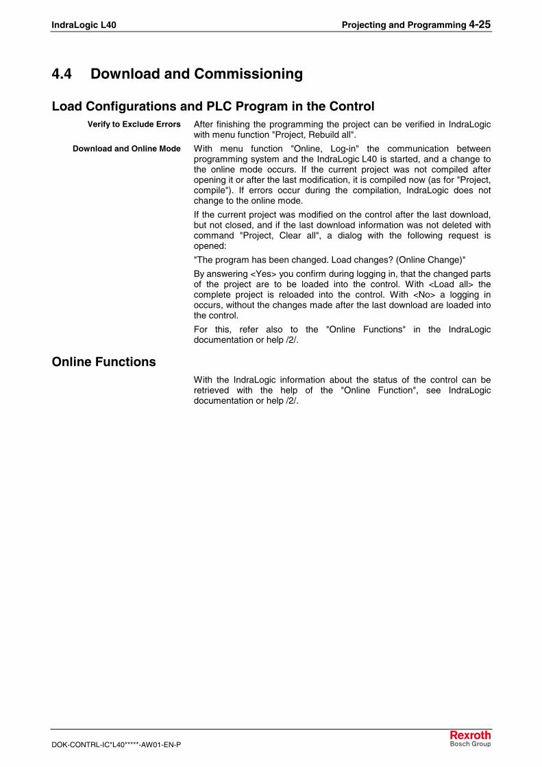
Create a PLC ProgramCreate a PLC program in IndraLogic.
For further information refer to the documentation or online help ofIndraLogic /2/.
Fig. 4-29: PLC program example
Save IndraLogic Project DataWith menu function "File, Save" all settings executed in IndraLogic and alledited blocks can be saved.
Note: Always save the IndraLogic project data at first, before youchange the current project in IndraWorks.
IndraLogic L40 Projecting and Programming 4-25
DOK-CONTRL-IC*L40*****-AW01-EN-P
4.4 Download and Commissioning
Load Configurations and PLC Program in the ControlAfter finishing the programming the project can be verified in IndraLogicwith menu function "Project, Rebuild all".
With menu function "Online, Log-in" the communication betweenprogramming system and the IndraLogic L40 is started, and a change tothe online mode occurs. If the current project was not compiled afteropening it or after the last modification, it is compiled now (as for "Project,compile"). If errors occur during the compilation, IndraLogic does notchange to the online mode.
If the current project was modified on the control after the last download,but not closed, and if the last download information was not deleted withcommand "Project, Clear all", a dialog with the following request isopened:
"The program has been changed. Load changes? (Online Change)"
By answering <Yes> you confirm during logging in, that the changed partsof the project are to be loaded into the control. With <Load all> thecomplete project is reloaded into the control. With <No> a logging inoccurs, without the changes made after the last download are loaded intothe control.
For this, refer also to the "Online Functions" in the IndraLogicdocumentation or help /2/.
Online FunctionsWith the IndraLogic information about the status of the control can beretrieved with the help of the "Online Function", see IndraLogicdocumentation or help /2/.
Verify to Exclude Errors
Download and Online Mode
4-26 Projecting and Programming IndraLogic L40
DOK-CONTRL-IC*L40*****-AW01-EN-P
IndraLogic L40 Further Functions 5-1
DOK-CONTRL-IC*L40*****-AW01-EN-P
5 Further Functions
5.1 Firmware Management
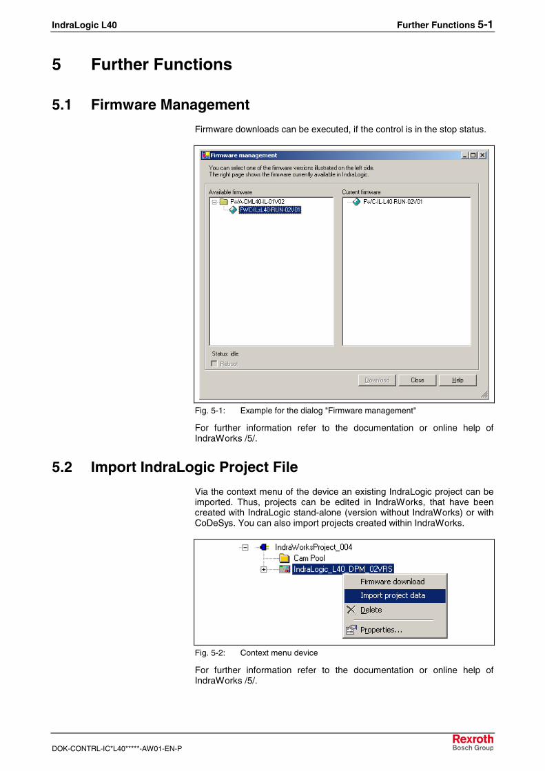
Firmware downloads can be executed, if the control is in the stop status.
Fig. 5-1: Example for the dialog "Firmware management"
For further information refer to the documentation or online help ofIndraWorks /5/.
5.2 Import IndraLogic Project File
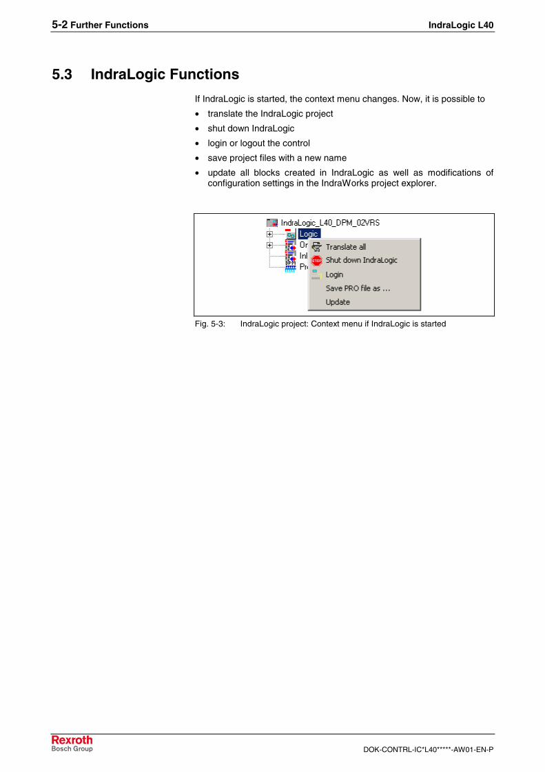
Via the context menu of the device an existing IndraLogic project can beimported. Thus, projects can be edited in IndraWorks, that have beencreated with IndraLogic stand-alone (version without IndraWorks) or withCoDeSys. You can also import projects created within IndraWorks.
Fig. 5-2: Context menu device
For further information refer to the documentation or online help ofIndraWorks /5/.
5-2 Further Functions IndraLogic L40
DOK-CONTRL-IC*L40*****-AW01-EN-P
5.3 IndraLogic Functions
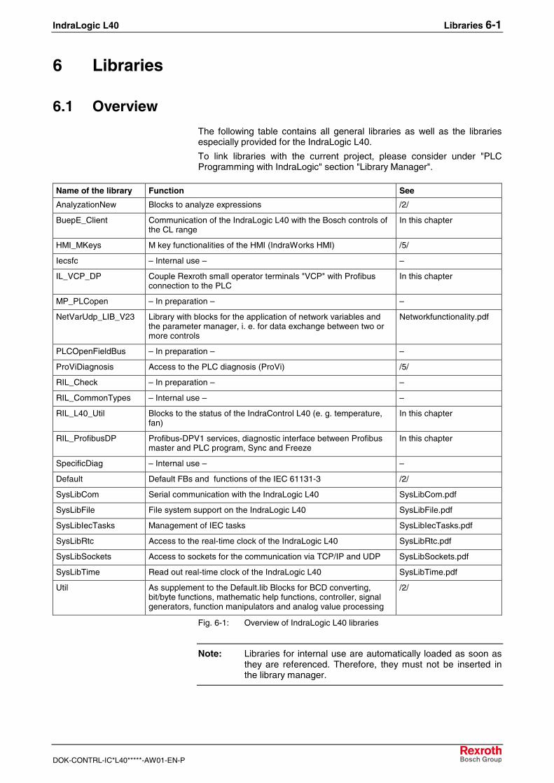
If IndraLogic is started, the context menu changes. Now, it is possible to
• translate the IndraLogic project
• shut down IndraLogic
• login or logout the control
• save project files with a new name
• update all blocks created in IndraLogic as well as modifications ofconfiguration settings in the IndraWorks project explorer.
Fig. 5-3: IndraLogic project: Context menu if IndraLogic is started
IndraLogic L40 Libraries 6-1
DOK-CONTRL-IC*L40*****-AW01-EN-P
6 Libraries
6.1 Overview
The following table contains all general libraries as well as the librariesespecially provided for the IndraLogic L40.
To link libraries with the current project, please consider under "PLCProgramming with IndraLogic" section "Library Manager".
Name of the library Function See
AnalyzationNew Blocks to analyze expressions /2/
BuepE_Client Communication of the IndraLogic L40 with the Bosch controls ofthe CL range
In this chapter
HMI_MKeys M key functionalities of the HMI (IndraWorks HMI) /5/
Iecsfc – Internal use – –
IL_VCP_DP Couple Rexroth small operator terminals "VCP" with Profibusconnection to the PLC
In this chapter
MP_PLCopen – In preparation – –
NetVarUdp_LIB_V23 Library with blocks for the application of network variables andthe parameter manager, i. e. for data exchange between two ormore controls
Networkfunctionality.pdf
PLCOpenFieldBus – In preparation – –
ProViDiagnosis Access to the PLC diagnosis (ProVi) /5/
RIL_Check – In preparation – –
RIL_CommonTypes – Internal use – –
RIL_L40_Util Blocks to the status of the IndraControl L40 (e. g. temperature,fan)
In this chapter
RIL_ProfibusDP Profibus-DPV1 services, diagnostic interface between Profibusmaster and PLC program, Sync and Freeze
In this chapter
SpecificDiag – Internal use – –
Default Default FBs and functions of the IEC 61131-3 /2/
SysLibCom Serial communication with the IndraLogic L40 SysLibCom.pdf
SysLibFile File system support on the IndraLogic L40 SysLibFile.pdf
SysLibIecTasks Management of IEC tasks SysLibIecTasks.pdf
SysLibRtc Access to the real-time clock of the IndraLogic L40 SysLibRtc.pdf
SysLibSockets Access to sockets for the communication via TCP/IP and UDP SysLibSockets.pdf
SysLibTime Read out real-time clock of the IndraLogic L40 SysLibTime.pdf
Util As supplement to the Default.lib Blocks for BCD converting,bit/byte functions, mathematic help functions, controller, signalgenerators, function manipulators and analog value processing
/2/
Fig. 6-1: Overview of IndraLogic L40 libraries
Note: Libraries for internal use are automatically loaded as soon asthey are referenced. Therefore, they must not be inserted inthe library manager.
6-2 Libraries IndraLogic L40
DOK-CONTRL-IC*L40*****-AW01-EN-P
Concerning the system and firmware libraries please also consider theonline help of IndraLogic. The documentation about the system libraries(SysLibXXX.pdf) you will find in a sub-directory of IndraLogic, e. g.:
C:/Program Files/Rexroth/IndraWorks/IndraLogic/Documents/German
6.2 BuepE_Client
GeneralLibrary BuepE_Client serves for the communication of the IndraLogic L40with the Bosch controls of the CL range.
The IndraLogic L40 maps the Client functionality. The CL controlrepresents always the server.
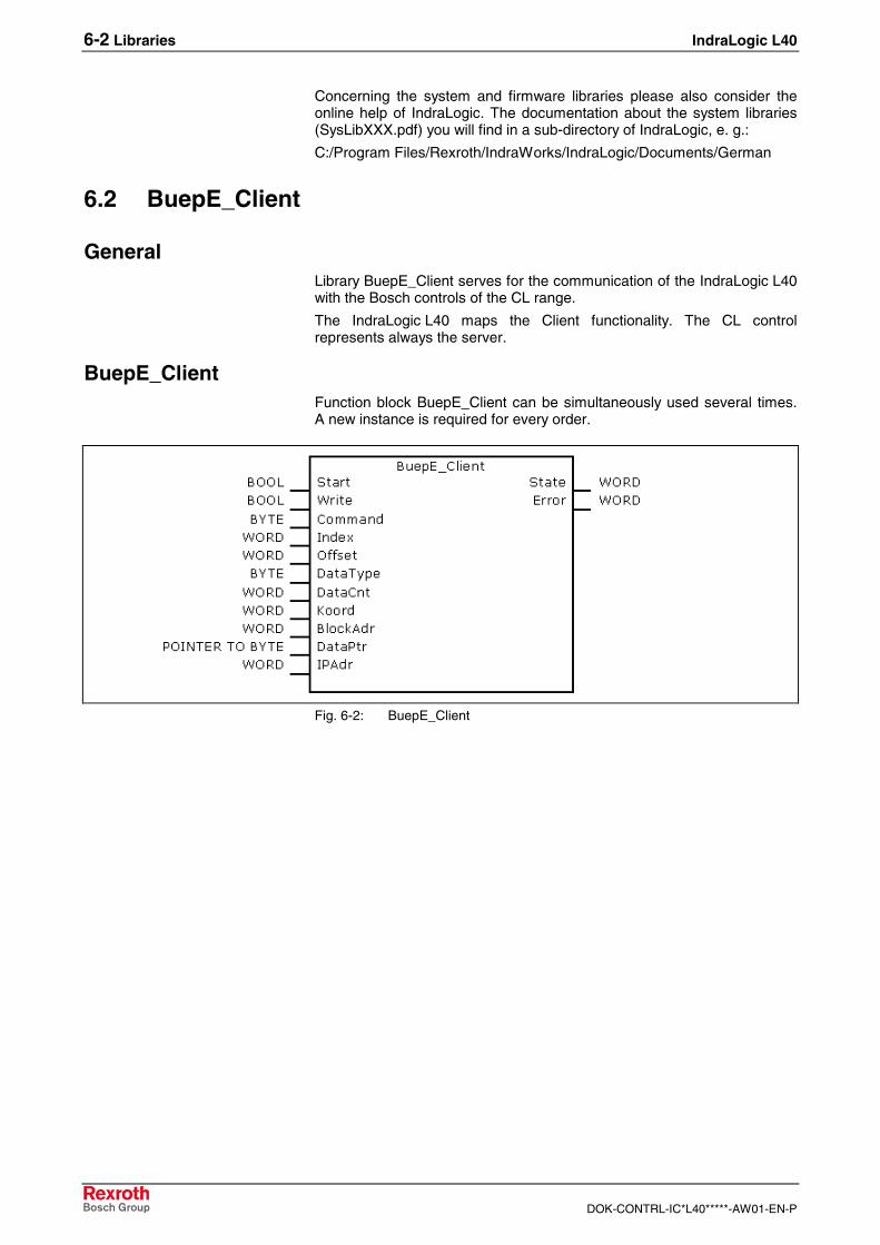
BuepE_ClientFunction block BuepE_Client can be simultaneously used several times.A new instance is required for every order.
Fig. 6-2: BuepE_Client
IndraLogic L40 Libraries 6-3
DOK-CONTRL-IC*L40*****-AW01-EN-P
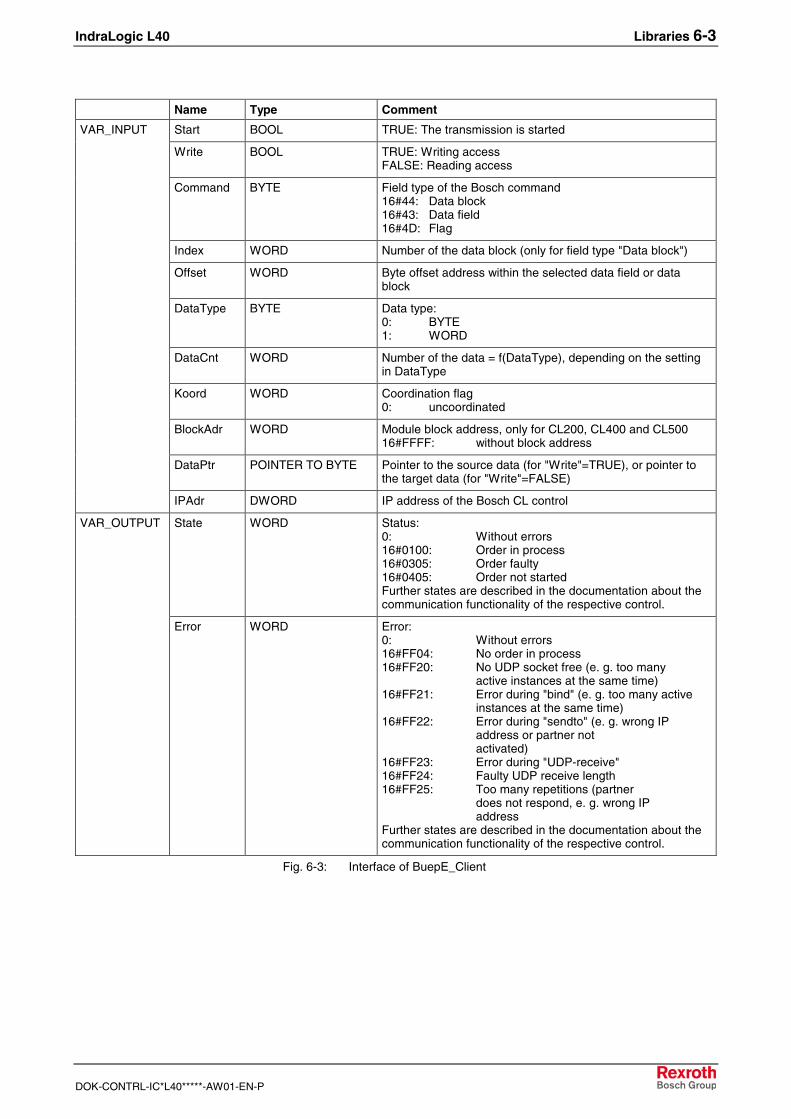
Name Type Comment
Start BOOL TRUE: The transmission is started
Write BOOL TRUE: Writing accessFALSE: Reading access
Command BYTE Field type of the Bosch command16#44: Data block16#43: Data field16#4D: Flag
Index WORD Number of the data block (only for field type "Data block")
Offset WORD Byte offset address within the selected data field or datablock
DataType BYTE Data type:0: BYTE1: WORD
DataCnt WORD Number of the data = f(DataType), depending on the settingin DataType
Koord WORD Coordination flag0: uncoordinated
BlockAdr WORD Module block address, only for CL200, CL400 and CL50016#FFFF: without block address
DataPtr POINTER TO BYTE Pointer to the source data (for "Write"=TRUE), or pointer tothe target data (for "Write"=FALSE)
VAR_INPUT
IPAdr DWORD IP address of the Bosch CL control
State WORD Status:0: Without errors16#0100: Order in process16#0305: Order faulty16#0405: Order not startedFurther states are described in the documentation about thecommunication functionality of the respective control.
VAR_OUTPUT
Error WORD Error:0: Without errors16#FF04: No order in process16#FF20: No UDP socket free (e. g. too many
active instances at the same time)16#FF21: Error during "bind" (e. g. too many active
instances at the same time)16#FF22: Error during "sendto" (e. g. wrong IP
address or partner notactivated)
16#FF23: Error during "UDP-receive"16#FF24: Faulty UDP receive length16#FF25: Too many repetitions (partner
does not respond, e. g. wrong IPaddress
Further states are described in the documentation about thecommunication functionality of the respective control.
Fig. 6-3: Interface of BuepE_Client
6-4 Libraries IndraLogic L40
DOK-CONTRL-IC*L40*****-AW01-EN-P
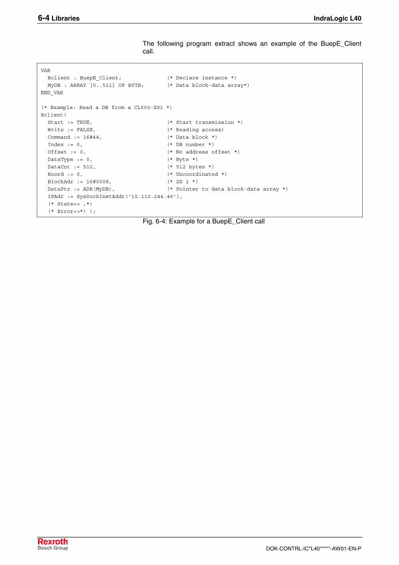
The following program extract shows an example of the BuepE_Clientcall.
VAR
Bclient : BuepE_Client; (* Declare instance *)
MyDB : ARRAY [0..511] OF BYTE; (* Data block-data array*)
END_VAR
(* Example: Read a DB from a CL500-ZS1 *)
Bclient(
Start := TRUE, (* Start transmission *)
Write := FALSE, (* Reading access)
Command := 16#44, (* Data block *)
Index := 0, (* DB number *)
Offset := 0, (* No address offset *)
DataType := 0, (* Byte *)
DataCnt := 512, (* 512 bytes *)
Koord := 0, (* Uncoordinated *)
BlockAdr := 16#0008, (* ZS 1 *)
DataPtr := ADR(MyDB), (* Pointer to data block-data array *)
IPAdr := SysSockInetAddr('10.110.244.46'),
(* State=> ,*)
(* Error=>*) );
Fig. 6-4: Example for a BuepE_Client call
IndraLogic L40 Libraries 6-5
DOK-CONTRL-IC*L40*****-AW01-EN-P
6.3 IL_VCP_DP
OverviewWith this library the small operator terminals "VCP of Rexroth withProfibus connection are coupled to the PLC. For this, three functionblocks can be alternatively used:
• VCP_PBS16_A4096
• VCP_PBS32_A4096
• VCP_PBS32_A65536
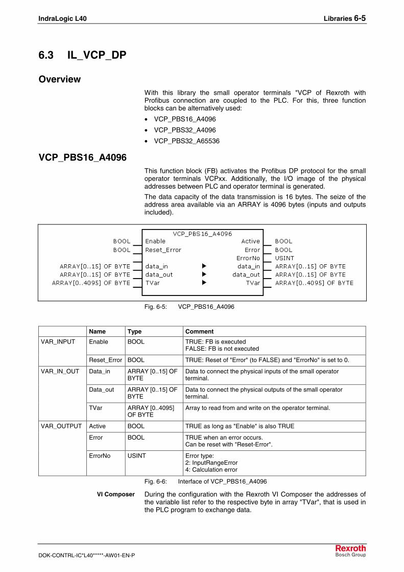
VCP_PBS16_A4096This function block (FB) activates the Profibus DP protocol for the smalloperator terminals VCPxx. Additionally, the I/O image of the physicaladdresses between PLC and operator terminal is generated.
The data capacity of the data transmission is 16 bytes. The seize of theaddress area available via an ARRAY is 4096 bytes (inputs and outputsincluded).
Fig. 6-5: VCP_PBS16_A4096
Name Type Comment
Enable BOOL TRUE: FB is executedFALSE: FB is not executed
VAR_INPUT
Reset_Error BOOL TRUE: Reset of "Error" (to FALSE) and "ErrorNo" is set to 0.
Data_in ARRAY [0..15] OFBYTE
Data to connect the physical inputs of the small operatorterminal.
Data_out ARRAY [0..15] OFBYTE
Data to connect the physical outputs of the small operatorterminal.
VAR_IN_OUT
TVar ARRAY [0..4095]OF BYTE
Array to read from and write on the operator terminal.
Active BOOL TRUE as long as "Enable" is also TRUE
Error BOOL TRUE when an error occurs.Can be reset with "Reset-Error".
VAR_OUTPUT
ErrorNo USINT Error type:2: InputRangeError4: Calculation error
Fig. 6-6: Interface of VCP_PBS16_A4096
During the configuration with the Rexroth VI Composer the addresses ofthe variable list refer to the respective byte in array "TVar", that is used inthe PLC program to exchange data.
VI Composer
6-6 Libraries IndraLogic L40
DOK-CONTRL-IC*L40*****-AW01-EN-P
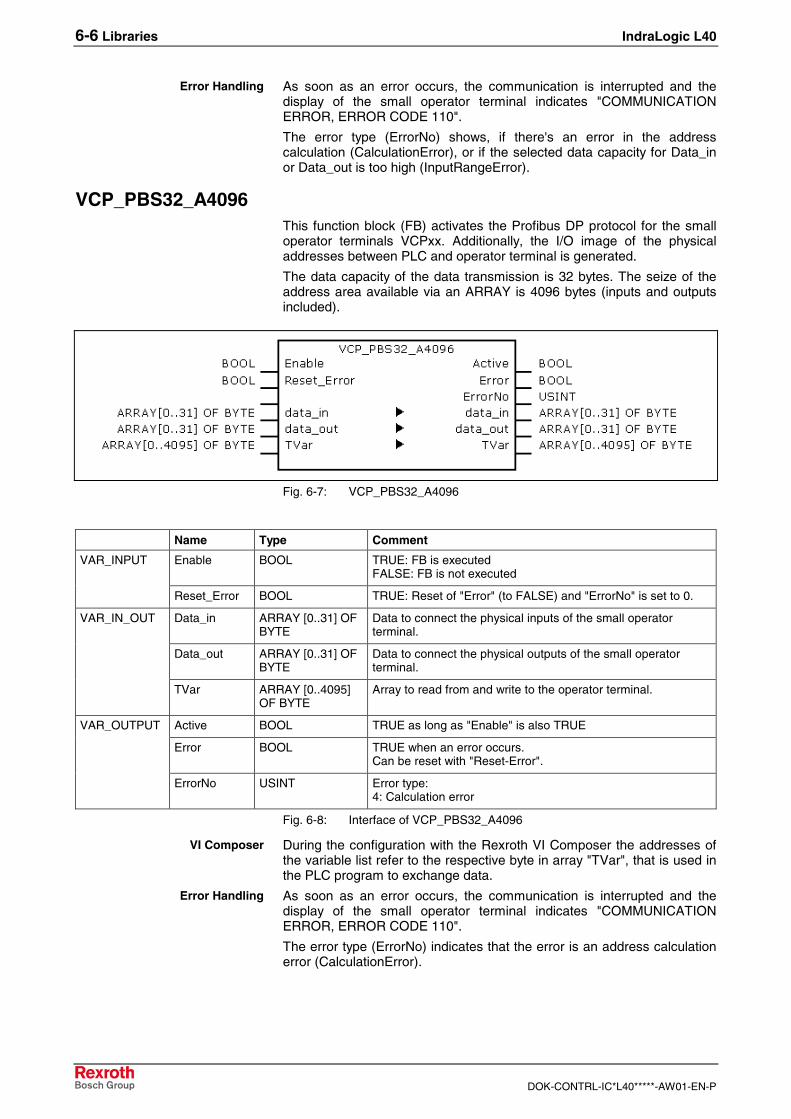
As soon as an error occurs, the communication is interrupted and thedisplay of the small operator terminal indicates "COMMUNICATIONERROR, ERROR CODE 110".
The error type (ErrorNo) shows, if there's an error in the addresscalculation (CalculationError), or if the selected data capacity for Data_inor Data_out is too high (InputRangeError).
VCP_PBS32_A4096This function block (FB) activates the Profibus DP protocol for the smalloperator terminals VCPxx. Additionally, the I/O image of the physicaladdresses between PLC and operator terminal is generated.
The data capacity of the data transmission is 32 bytes. The seize of theaddress area available via an ARRAY is 4096 bytes (inputs and outputsincluded).
Fig. 6-7: VCP_PBS32_A4096
Name Type Comment
Enable BOOL TRUE: FB is executedFALSE: FB is not executed
VAR_INPUT
Reset_Error BOOL TRUE: Reset of "Error" (to FALSE) and "ErrorNo" is set to 0.
Data_in ARRAY [0..31] OFBYTE
Data to connect the physical inputs of the small operatorterminal.
Data_out ARRAY [0..31] OFBYTE
Data to connect the physical outputs of the small operatorterminal.
VAR_IN_OUT
TVar ARRAY [0..4095]OF BYTE
Array to read from and write to the operator terminal.
Active BOOL TRUE as long as "Enable" is also TRUE
Error BOOL TRUE when an error occurs.Can be reset with "Reset-Error".
VAR_OUTPUT
ErrorNo USINT Error type:4: Calculation error
Fig. 6-8: Interface of VCP_PBS32_A4096
During the configuration with the Rexroth VI Composer the addresses ofthe variable list refer to the respective byte in array "TVar", that is used inthe PLC program to exchange data.
As soon as an error occurs, the communication is interrupted and thedisplay of the small operator terminal indicates "COMMUNICATIONERROR, ERROR CODE 110".
The error type (ErrorNo) indicates that the error is an address calculationerror (CalculationError).
Error Handling
VI Composer
Error Handling

IndraLogic L40 Libraries 6-7
DOK-CONTRL-IC*L40*****-AW01-EN-P
VCP_PBS32_A65536This function block (FB) activates the Profibus DP protocol for the smalloperator terminals VCPxx. Additionally, the I/O image of the physicaladdresses between PLC and operator terminal is generated.
The data capacity of the data transmission is 32 bytes. The seize of theaddress area available via an ARRAY is 65536 bytes (inputs and outputsincluded).
Fig. 6-9: VCP_PBS32_A65536
Name Type Comment
Enable BOOL TRUE: FB is executedFALSE: FB is not executed
VAR_INPUT
Reset_Error BOOL TRUE: Reset of "Error" (to FALSE) and "ErrorNo" is set to 0.
Data_in ARRAY [0..31] OFBYTE
Data to connect the physical inputs of the small operatorterminal.
Data_out ARRAY [0..31] OFBYTE
Data to connect the physical outputs of the small operatorterminal.
VAR_IN_OUT
TVar ARRAY [0..65535]OF BYTE
Array to read from and write to the operator terminal.
Active BOOL TRUE, as long as "Enable" is also TRUE
Error BOOL TRUE when an error occurs.Can be reset with "Reset-Error".
VAR_OUTPUT
ErrorNo USINT Error type:4: Calculation error
Fig. 6-10: Interface of VCP_PBS32_A65536
During the configuration with the Rexroth VI Composer the addresses ofthe variable list refer to the respective byte in array "TVar", that is used inthe PLC program to exchange data.
As soon as an error occurs, the communication is interrupted and thedisplay of the small operator terminal indicates "COMMUNICATIONERROR, ERROR CODE 110".
The error type (ErrorNo) indicates that the error is an address calculationerror (CalculationError).
VI Composer
Error Handling
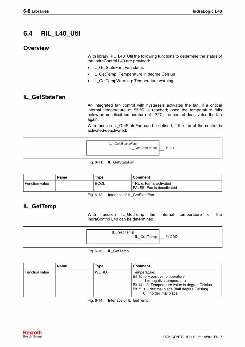
6-8 Libraries IndraLogic L40
DOK-CONTRL-IC*L40*****-AW01-EN-P
6.4 RIL_L40_Util
OverviewWith library RIL_L40_Util the following functions to determine the status ofthe IndraControl L40 are provided:
• IL_GetStateFan: Fan status
• IL_GetTemp: Temperature in degree Celsius
• IL_GetTempWarning: Temperature warning
IL_GetStateFanAn integrated fan control with hysteresis activates the fan, if a criticalinternal temperature of 55 °C is reached; once the temperature fallsbelow an uncritical temperature of 42 °C, the control deactivates the fanagain.
With function IL_GetStateFan can be defined, if the fan of the control isactivated/deactivated.
Fig. 6-11: IL_GetStateFan
Name Type Comment
Function value BOOL TRUE: Fan is activatedFALSE: Fan is deactivated
Fig. 6-12: Interface of IL_GetStateFan
IL_GetTempWith function IL_GetTemp the internal temperature of theIndraControl L40 can be determined.
Fig. 6-13: IL_GetTemp
Name Type Comment
Function value WORD Temperature:Bit 15: 0 = positive temperature 1 = negative temperatureBit 14 – 8: Temperature value in degree CelsiusBit 7: 1 = decimal place (half degree Celsius) 0 = no decimal place
Fig. 6-14: Interface of IL_GetTemp
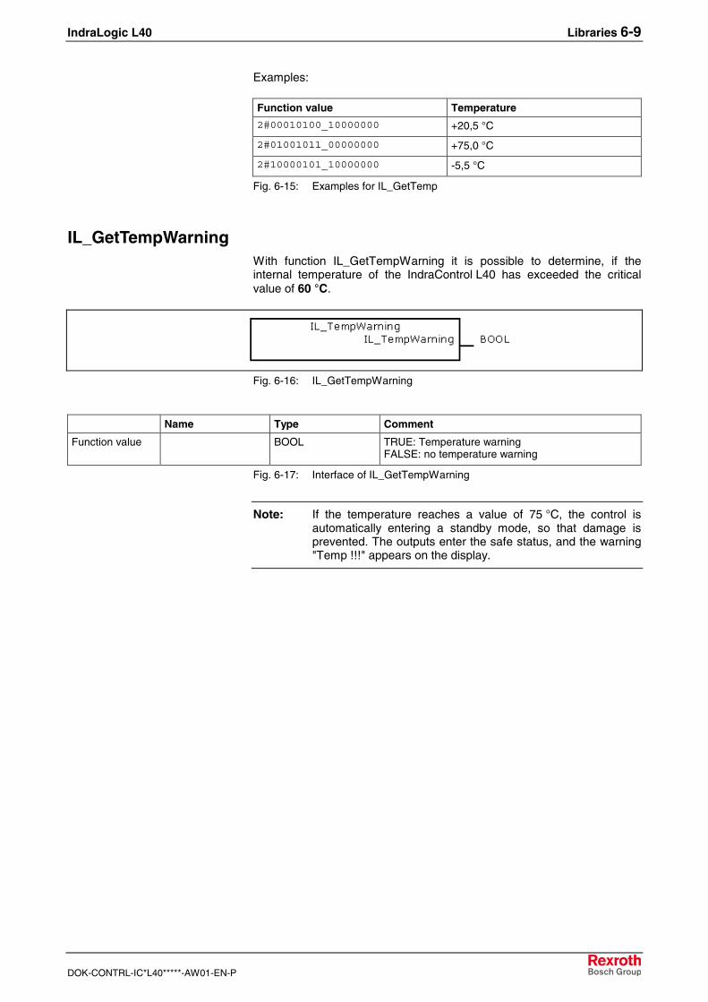
IndraLogic L40 Libraries 6-9
DOK-CONTRL-IC*L40*****-AW01-EN-P
Examples:
Function value Temperature
2#00010100_10000000 +20,5 °C
2#01001011_00000000 +75,0 °C
2#10000101_10000000 -5,5 °C
Fig. 6-15: Examples for IL_GetTemp
IL_GetTempWarningWith function IL_GetTempWarning it is possible to determine, if theinternal temperature of the IndraControl L40 has exceeded the criticalvalue of 60 °C.
Fig. 6-16: IL_GetTempWarning
Name Type Comment
Function value BOOL TRUE: Temperature warningFALSE: no temperature warning
Fig. 6-17: Interface of IL_GetTempWarning
Note: If the temperature reaches a value of 75 °C, the control isautomatically entering a standby mode, so that damage isprevented. The outputs enter the safe status, and the warning"Temp !!!" appears on the display.
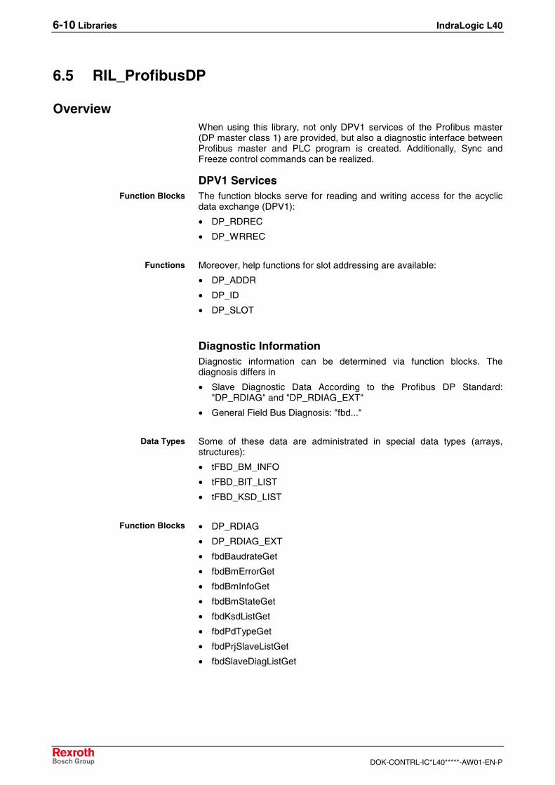
6-10 Libraries IndraLogic L40
DOK-CONTRL-IC*L40*****-AW01-EN-P
6.5 RIL_ProfibusDP
OverviewWhen using this library, not only DPV1 services of the Profibus master(DP master class 1) are provided, but also a diagnostic interface betweenProfibus master and PLC program is created. Additionally, Sync andFreeze control commands can be realized.
DPV1 ServicesThe function blocks serve for reading and writing access for the acyclicdata exchange (DPV1):
• DP_RDREC
• DP_WRREC
Moreover, help functions for slot addressing are available:
• DP_ADDR
• DP_ID
• DP_SLOT
Diagnostic InformationDiagnostic information can be determined via function blocks. Thediagnosis differs in
• Slave Diagnostic Data According to the Profibus DP Standard:"DP_RDIAG" and "DP_RDIAG_EXT"
• General Field Bus Diagnosis: "fbd..."
Some of these data are administrated in special data types (arrays,structures):
• tFBD_BM_INFO
• tFBD_BIT_LIST
• tFBD_KSD_LIST
• DP_RDIAG
• DP_RDIAG_EXT
• fbdBaudrateGet
• fbdBmErrorGet
• fbdBmInfoGet
• fbdBmStateGet
• fbdKsdListGet
• fbdPdTypeGet
• fbdPrjSlaveListGet
• fbdSlaveDiagListGet
Function Blocks
Functions
Data Types
Function Blocks
IndraLogic L40 Libraries 6-11
DOK-CONTRL-IC*L40*****-AW01-EN-P
Moreover, help functions for slot addressing are available:
• DP_ADDR
• DP_ID
• DP_SLOT
Sync and FreezeControl commands to synchronize inputs or outputs.
• DP_SYCFR
Moreover, help functions for slot addressing are available:
• DP_ADDR
• DP_ID
• DP_SLOT
Slave Diagnostic Data According to the Profibus DP StandardProfibus-specific diagnostic information according to the Profibus DPstandard can be read via the following function blocks:
• DP_RDIAG
• DP_RDIAG_EXT
The slave diagnostic data are available with the parameters DINFO orDINFO_PTR. While for "DINFO" all diagnostic data are archived in anarray, "DINFO_PTR" is a pointer to the diagnostic data.
The slave diagnostic data are subdivided into two parts:
• general part with a fixed length of 6 bytes
• extended diagnosis (slave-specific, with variable length)
Offset Type Designation Description
0 BYTE Station status_1 See below
1 BYTE Station status_2 See below
2 BYTE Station status_3 See below
3 BYTE Master_Add Bus address of the master havingparameterized the slave
4 WORD Ident_Number Ident_Number of the slave
6 – 243 Ext_Diag_Data Extended slave diagnosisaccording to Profibus DP standard
Fig. 6-18: Slave diagnostic data
The following description of the station status 1 to 3 is an extract from theProfibus DP standard.
Functions
Functions
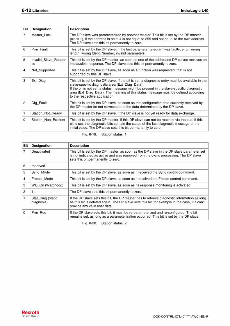
6-12 Libraries IndraLogic L40
DOK-CONTRL-IC*L40*****-AW01-EN-P
Bit Designation Description
7 Master_Lock The DP slave was parameterized by another master. This bit is set by the DP master(class 1), if the address in octet 4 is not equal to 255 and not equal to the own address.The DP slave sets this bit permanently to zero.
6 Prm_Fault This bit is set by the DP slave, if the last parameter telegram was faulty, e. g., wronglength, wrong Ident_Number, invalid parameters.
5 Invalid_Slave_Response
This bit is set by the DP master, as soon as one of the addressed DP slaves receives animplausible response. The DP slave sets this bit permanently to zero.
4 Not_Supported This bit is set by the DP slave, as soon as a function was requested, that is notsupported by this DP slave.
3 Ext_Diag This bit is set by the DP slave. If the bit is set, a diagnostic entry must be available in theslave-specific diagnostic area (Ext_Diag_Data).If the bit is not set, a status message might be present in the slave-specific diagnosticarea (Ext_Diag_Data). The meaning of this status message must be defined accordingto the respective application.
2 Cfg_Fault This bit is set by the DP slave, as soon as the configuration data currently received bythe DP master do not correspond to the data determined by the DP slave.
1 Station_Not_Ready This bit is set by the DP slave, if the DP slave is not yet ready for data exchange.
0 Station_Non_Existent This bit is set by the DP master, if this DP slave can not be reached via the bus. If thisbit is set, the diagnostic bits contain the status of the last diagnostic message or theinitial value. The DP slave sets this bit permanently to zero.
Fig. 6-19: Station status_1
Bit Designation Description
7 Deactivated This bit is set by the DP master, as soon as the DP slave in the DP slave parameter setis not indicated as active and was removed from the cyclic processing. The DP slavesets this bit permanently to zero.
6 reserved -
5 Sync_Mode This bit is set by the DP slave, as soon as it received the Sync control command.
4 Freeze_Mode This bit is set by the DP slave, as soon as it received the Freeze control command.
3 WD_On (Watchdog) This bit is set by the DP slave, as soon as its response monitoring is activated.
2 1 The DP slave sets this bit permanently to zero.
1 Stat_Diag (staticdiagnosis)
If the DP slave sets this bit, the DP master has to retrieve diagnostic information as longas this bit is deleted again. The DP slave sets this bit, for example in the case, if it can'tprovide any valid user data.
0 Prm_Req If the DP slave sets this bit, it must be re-parameterized and re-configured. The bitremains set, as long as a parameterization occurred. This bit is set by the DP slave.
Fig. 6-20: Station status_2
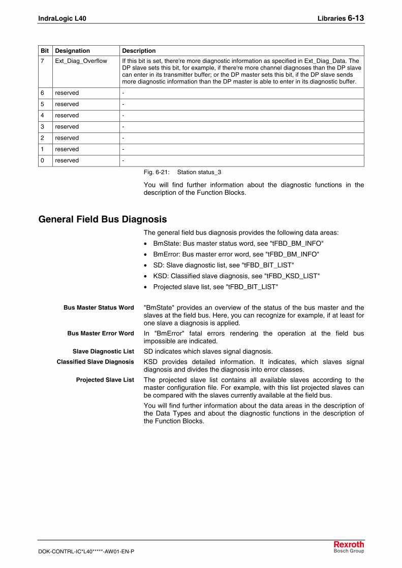
IndraLogic L40 Libraries 6-13
DOK-CONTRL-IC*L40*****-AW01-EN-P
Bit Designation Description
7 Ext_Diag_Overflow If this bit is set, there're more diagnostic information as specified in Ext_Diag_Data. TheDP slave sets this bit, for example, if there're more channel diagnoses than the DP slavecan enter in its transmitter buffer; or the DP master sets this bit, if the DP slave sendsmore diagnostic information than the DP master is able to enter in its diagnostic buffer.
6 reserved -
5 reserved -
4 reserved -
3 reserved -
2 reserved -
1 reserved -
0 reserved -
Fig. 6-21: Station status_3
You will find further information about the diagnostic functions in thedescription of the Function Blocks.
General Field Bus DiagnosisThe general field bus diagnosis provides the following data areas:
• BmState: Bus master status word, see "tFBD_BM_INFO"
• BmError: Bus master error word, see "tFBD_BM_INFO"
• SD: Slave diagnostic list, see "tFBD_BIT_LIST"
• KSD: Classified slave diagnosis, see "tFBD_KSD_LIST"
• Projected slave list, see "tFBD_BIT_LIST"
"BmState" provides an overview of the status of the bus master and theslaves at the field bus. Here, you can recognize for example, if at least forone slave a diagnosis is applied.
In "BmError" fatal errors rendering the operation at the field busimpossible are indicated.
SD indicates which slaves signal diagnosis.
KSD provides detailed information. It indicates, which slaves signaldiagnosis and divides the diagnosis into error classes.
The projected slave list contains all available slaves according to themaster configuration file. For example, with this list projected slaves canbe compared with the slaves currently available at the field bus.
You will find further information about the data areas in the description ofthe Data Types and about the diagnostic functions in the description ofthe Function Blocks.
Bus Master Status Word
Bus Master Error Word
Slave Diagnostic List
Classified Slave Diagnosis
Projected Slave List
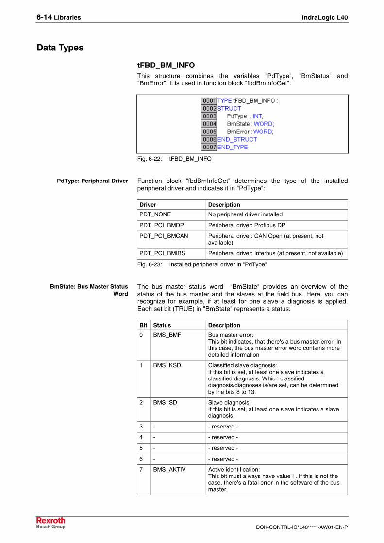
6-14 Libraries IndraLogic L40
DOK-CONTRL-IC*L40*****-AW01-EN-P
Data Types
tFBD_BM_INFOThis structure combines the variables "PdType", "BmStatus" and"BmError". It is used in function block "fbdBmInfoGet".
Fig. 6-22: tFBD_BM_INFO
Function block "fbdBmInfoGet" determines the type of the installedperipheral driver and indicates it in "PdType":
Driver Description
PDT_NONE No peripheral driver installed
PDT_PCI_BMDP Peripheral driver: Profibus DP
PDT_PCI_BMCAN Peripheral driver: CAN Open (at present, notavailable)
PDT_PCI_BMIBS Peripheral driver: Interbus (at present, not available)
Fig. 6-23: Installed peripheral driver in "PdType"
The bus master status word "BmState" provides an overview of thestatus of the bus master and the slaves at the field bus. Here, you canrecognize for example, if at least for one slave a diagnosis is applied.Each set bit (TRUE) in "BmState" represents a status:
Bit Status Description
0 BMS_BMF Bus master error:This bit indicates, that there's a bus master error. Inthis case, the bus master error word contains moredetailed information
1 BMS_KSD Classified slave diagnosis:If this bit is set, at least one slave indicates aclassified diagnosis. Which classifieddiagnosis/diagnoses is/are set, can be determinedby the bits 8 to 13.
2 BMS_SD Slave diagnosis:If this bit is set, at least one slave indicates a slavediagnosis.
3 - - reserved -
4 - - reserved -
5 - - reserved -
6 - - reserved -
7 BMS_AKTIV Active identification:This bit must always have value 1. If this is not thecase, there's a fatal error in the software of the busmaster.
PdType: Peripheral Driver
BmState: Bus Master StatusWord
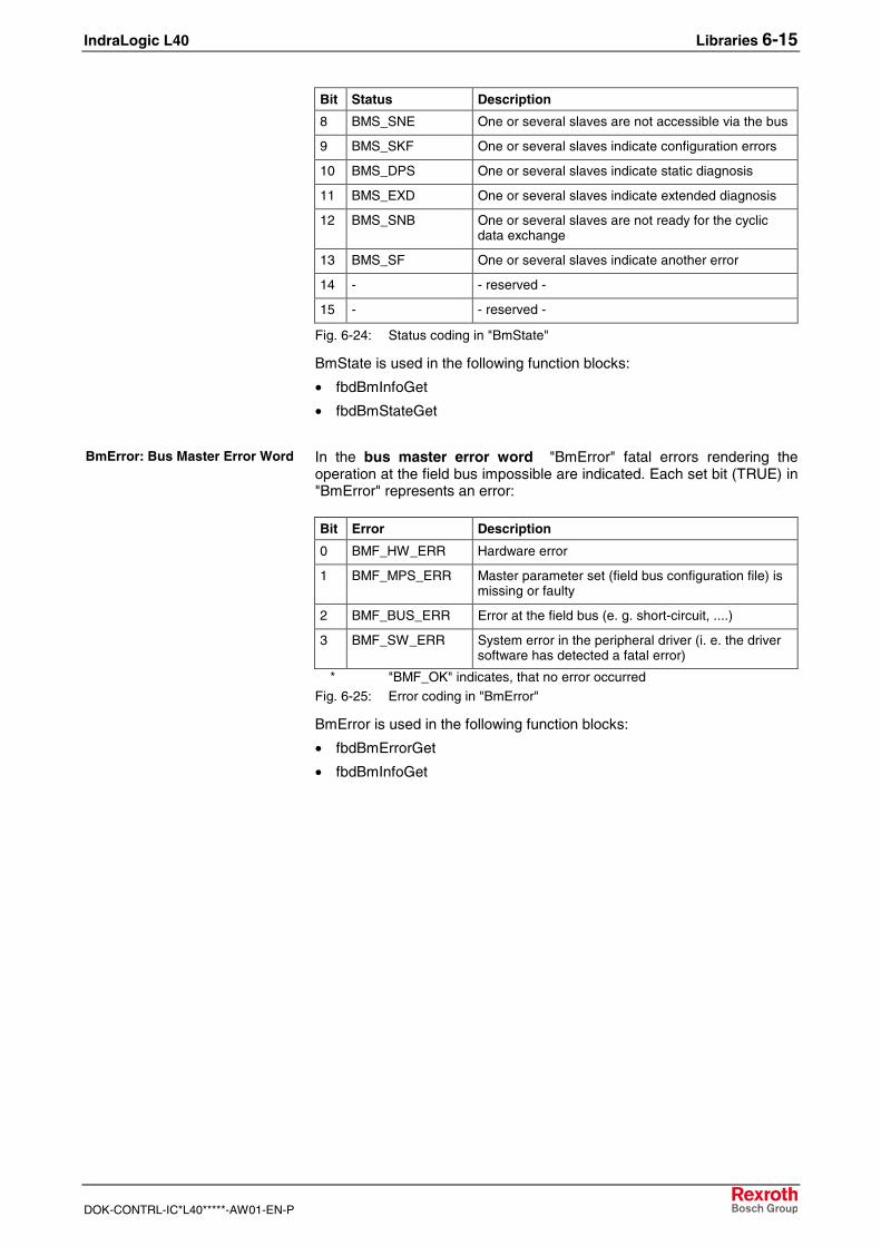
IndraLogic L40 Libraries 6-15
DOK-CONTRL-IC*L40*****-AW01-EN-P
Bit Status Description
8 BMS_SNE One or several slaves are not accessible via the bus
9 BMS_SKF One or several slaves indicate configuration errors
10 BMS_DPS One or several slaves indicate static diagnosis
11 BMS_EXD One or several slaves indicate extended diagnosis
12 BMS_SNB One or several slaves are not ready for the cyclicdata exchange
13 BMS_SF One or several slaves indicate another error
14 - - reserved -
15 - - reserved -
Fig. 6-24: Status coding in "BmState"
BmState is used in the following function blocks:
• fbdBmInfoGet
• fbdBmStateGet
In the bus master error word "BmError" fatal errors rendering theoperation at the field bus impossible are indicated. Each set bit (TRUE) in"BmError" represents an error:
Bit Error Description
0 BMF_HW_ERR Hardware error
1 BMF_MPS_ERR Master parameter set (field bus configuration file) ismissing or faulty
2 BMF_BUS_ERR Error at the field bus (e. g. short-circuit, ....)
3 BMF_SW_ERR System error in the peripheral driver (i. e. the driversoftware has detected a fatal error)
* "BMF_OK" indicates, that no error occurredFig. 6-25: Error coding in "BmError"
BmError is used in the following function blocks:
• fbdBmErrorGet
• fbdBmInfoGet
BmError: Bus Master Error Word
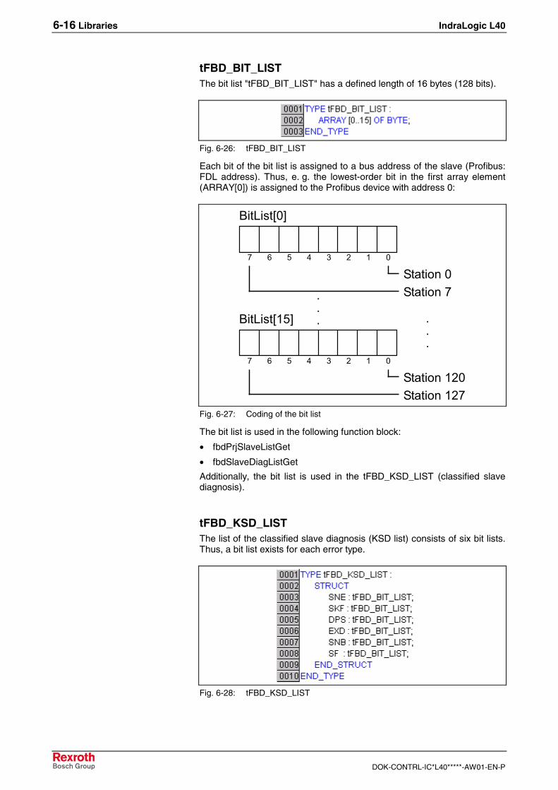
6-16 Libraries IndraLogic L40
DOK-CONTRL-IC*L40*****-AW01-EN-P
tFBD_BIT_LISTThe bit list "tFBD_BIT_LIST" has a defined length of 16 bytes (128 bits).
Fig. 6-26: tFBD_BIT_LIST
Each bit of the bit list is assigned to a bus address of the slave (Profibus:FDL address). Thus, e. g. the lowest-order bit in the first array element(ARRAY[0]) is assigned to the Profibus device with address 0:
�������������������������������������������������
��� ������ ����
� �� ����
�������������������������������������������������
��� �������� ������
� �� ������
��� �
��
Fig. 6-27: Coding of the bit list
The bit list is used in the following function block:
• fbdPrjSlaveListGet
• fbdSlaveDiagListGet
Additionally, the bit list is used in the tFBD_KSD_LIST (classified slavediagnosis).
tFBD_KSD_LISTThe list of the classified slave diagnosis (KSD list) consists of six bit lists.Thus, a bit list exists for each error type.
Fig. 6-28: tFBD_KSD_LIST
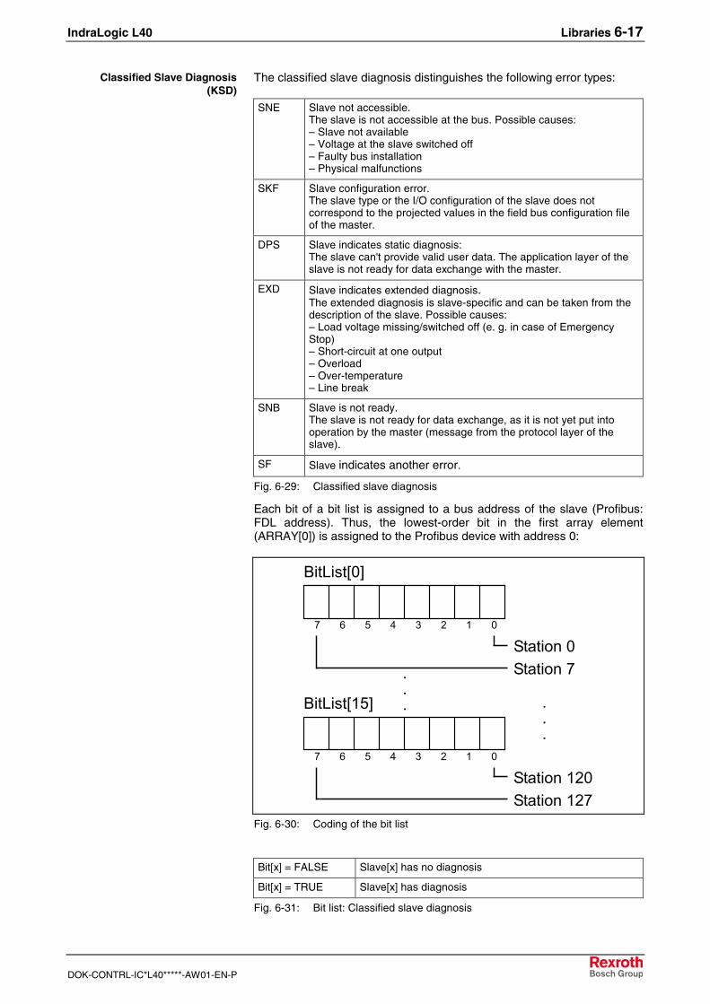
IndraLogic L40 Libraries 6-17
DOK-CONTRL-IC*L40*****-AW01-EN-P
The classified slave diagnosis distinguishes the following error types:
SNE Slave not accessible.The slave is not accessible at the bus. Possible causes:– Slave not available– Voltage at the slave switched off– Faulty bus installation– Physical malfunctions
SKF Slave configuration error.The slave type or the I/O configuration of the slave does notcorrespond to the projected values in the field bus configuration fileof the master.
DPS Slave indicates static diagnosis:The slave can't provide valid user data. The application layer of theslave is not ready for data exchange with the master.
EXD Slave indicates extended diagnosis.The extended diagnosis is slave-specific and can be taken from thedescription of the slave. Possible causes:– Load voltage missing/switched off (e. g. in case of EmergencyStop)– Short-circuit at one output– Overload– Over-temperature– Line break
SNB Slave is not ready.The slave is not ready for data exchange, as it is not yet put intooperation by the master (message from the protocol layer of theslave).
SF Slave indicates another error.
Fig. 6-29: Classified slave diagnosis
Each bit of a bit list is assigned to a bus address of the slave (Profibus:FDL address). Thus, the lowest-order bit in the first array element(ARRAY[0]) is assigned to the Profibus device with address 0:
�������������������������������������������������
��� ������ ����
� �� ����
�������������������������������������������������
��� �������� ������
� �� ������
��� �
��
Fig. 6-30: Coding of the bit list
Bit[x] = FALSE Slave[x] has no diagnosis
Bit[x] = TRUE Slave[x] has diagnosis
Fig. 6-31: Bit list: Classified slave diagnosis
Classified Slave Diagnosis(KSD)
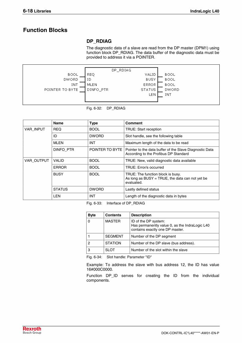
6-18 Libraries IndraLogic L40
DOK-CONTRL-IC*L40*****-AW01-EN-P
Function Blocks
DP_RDIAGThe diagnostic data of a slave are read from the DP master (DPM1) usingfunction block DP_RDIAG. The data buffer of the diagnostic data must beprovided to address it via a POINTER.
Fig. 6-32: DP_RDIAG
Name Type Comment
REQ BOOL TRUE: Start reception
ID DWORD Slot handle, see the following table
MLEN INT Maximum length of the data to be read
VAR_INPUT
DINFO_PTR POINTER TO BYTE Pointer to the data buffer of the Slave Diagnostic DataAccording to the Profibus DP Standard
VALID BOOL TRUE: New, valid diagnostic data available
ERROR BOOL TRUE: Error/s occurred
BUSY BOOL TRUE: The function block is busy.As long as BUSY = TRUE, the data can not yet beevaluated.
STATUS DWORD Lastly defined status
VAR_OUTPUT
LEN INT Length of the diagnostic data in bytes
Fig. 6-33: Interface of DP_RDIAG
Byte Contents Description
0 MASTER ID of the DP system:Has permanently value 0, as the IndraLogic L40contains exactly one DP master.
1 SEGMENT Number of the DP segment
2 STATION Number of the DP slave (bus address).
3 SLOT Number of the slot within the slave
Fig. 6-34: Slot handle: Parameter "ID"
Example: To address the slave with bus address 12, the ID has value16#000C0000.
Function DP_ID serves for creating the ID from the individualcomponents.
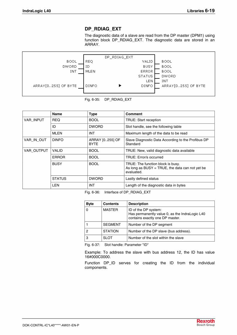
IndraLogic L40 Libraries 6-19
DOK-CONTRL-IC*L40*****-AW01-EN-P
DP_RDIAG_EXTThe diagnostic data of a slave are read from the DP master (DPM1) usingfunction block DP_RDIAG_EXT. The diagnostic data are stored in anARRAY.
Fig. 6-35: DP_RDIAG_EXT
Name Type Comment
REQ BOOL TRUE: Start reception
ID DWORD Slot handle, see the following table
VAR_INPUT
MLEN INT Maximum length of the data to be read
VAR_IN_OUT DINFO ARRAY [0..255] OFBYTE
Slave Diagnostic Data According to the Profibus DPStandard
VALID BOOL TRUE: New, valid diagnostic data available
ERROR BOOL TRUE: Error/s occurred
BUSY BOOL TRUE: The function block is busy.As long as BUSY = TRUE, the data can not yet beevaluated.
STATUS DWORD Lastly defined status
VAR_OUTPUT
LEN INT Length of the diagnostic data in bytes
Fig. 6-36: Interface of DP_RDIAG_EXT
Byte Contents Description
0 MASTER ID of the DP system:Has permanently value 0, as the IndraLogic L40contains exactly one DP master.
1 SEGMENT Number of the DP segment
2 STATION Number of the DP slave (bus address).
3 SLOT Number of the slot within the slave
Fig. 6-37: Slot handle: Parameter "ID"
Example: To address the slave with bus address 12, the ID has value16#000C0000.
Function DP_ID serves for creating the ID from the individualcomponents.
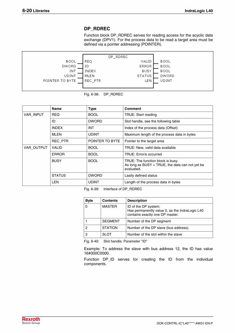
6-20 Libraries IndraLogic L40
DOK-CONTRL-IC*L40*****-AW01-EN-P
DP_RDRECFunction block DP_RDREC serves for reading access for the acyclic dataexchange (DPV1). For the process data to be read a target area must bedefined via a pointer addressing (POINTER).
Fig. 6-38: DP_RDREC
Name Type Comment
REQ BOOL TRUE: Start reading
ID DWORD Slot handle, see the following table
INDEX INT Index of the process data (Offset)
MLEN UDINT Maximum length of the process data in bytes
VAR_INPUT
REC_PTR POINTER TO BYTE Pointer to the target area
VALID BOOL TRUE: New, valid data available
ERROR BOOL TRUE: Error/s occurred
BUSY BOOL TRUE: The function block is busy.As long as BUSY = TRUE, the data can not yet beevaluated.
STATUS DWORD Lastly defined status
VAR_OUTPUT
LEN UDINT Length of the process data in bytes
Fig. 6-39: Interface of DP_RDREC
Byte Contents Description
0 MASTER ID of the DP system:Has permanently value 0, as the IndraLogic L40contains exactly one DP master.
1 SEGMENT Number of the DP segment
2 STATION Number of the DP slave (bus address).
3 SLOT Number of the slot within the slave
Fig. 6-40: Slot handle: Parameter "ID"
Example: To address the slave with bus address 12, the ID has value16#000C0000.
Function DP_ID serves for creating the ID from the individualcomponents.
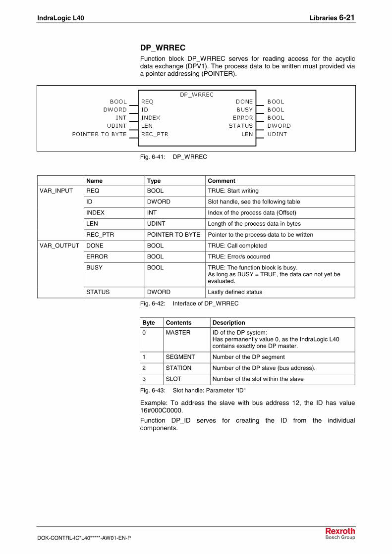
IndraLogic L40 Libraries 6-21
DOK-CONTRL-IC*L40*****-AW01-EN-P
DP_WRRECFunction block DP_WRREC serves for reading access for the acyclicdata exchange (DPV1). The process data to be written must provided viaa pointer addressing (POINTER).
Fig. 6-41: DP_WRREC
Name Type Comment
REQ BOOL TRUE: Start writing
ID DWORD Slot handle, see the following table
INDEX INT Index of the process data (Offset)
LEN UDINT Length of the process data in bytes
VAR_INPUT
REC_PTR POINTER TO BYTE Pointer to the process data to be written
DONE BOOL TRUE: Call completed
ERROR BOOL TRUE: Error/s occurred
BUSY BOOL TRUE: The function block is busy.As long as BUSY = TRUE, the data can not yet beevaluated.
VAR_OUTPUT
STATUS DWORD Lastly defined status
Fig. 6-42: Interface of DP_WRREC
Byte Contents Description
0 MASTER ID of the DP system:Has permanently value 0, as the IndraLogic L40contains exactly one DP master.
1 SEGMENT Number of the DP segment
2 STATION Number of the DP slave (bus address).
3 SLOT Number of the slot within the slave
Fig. 6-43: Slot handle: Parameter "ID"
Example: To address the slave with bus address 12, the ID has value16#000C0000.
Function DP_ID serves for creating the ID from the individualcomponents.
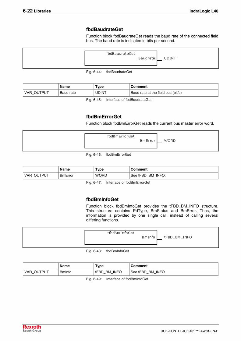
6-22 Libraries IndraLogic L40
DOK-CONTRL-IC*L40*****-AW01-EN-P
fbdBaudrateGetFunction block fbdBaudrateGet reads the baud rate of the connected fieldbus. The baud rate is indicated in bits per second.
Fig. 6-44: fbdBaudrateGet
Name Type Comment
VAR_OUTPUT Baud rate UDINT Baud rate at the field bus (bit/s)
Fig. 6-45: Interface of fbdBaudrateGet
fbdBmErrorGetFunction block fbdBmErrorGet reads the current bus master error word.
Fig. 6-46: fbdBmErrorGet
Name Type Comment
VAR_OUTPUT BmError WORD See tFBD_BM_INFO.
Fig. 6-47: Interface of fbdBmErrorGet
fbdBmInfoGetFunction block fbdBmInfoGet provides the tFBD_BM_INFO structure.This structure contains PdType, BmStatus and BmError. Thus, theinformation is provided by one single call, instead of calling severaldiffering functions.
Fig. 6-48: fbdBmInfoGet
Name Type Comment
VAR_OUTPUT BmInfo tFBD_BM_INFO See tFBD_BM_INFO.
Fig. 6-49: Interface of fbdBmInfoGet
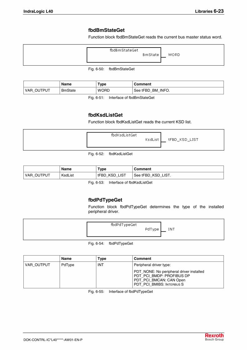
IndraLogic L40 Libraries 6-23
DOK-CONTRL-IC*L40*****-AW01-EN-P
fbdBmStateGetFunction block fbdBmStateGet reads the current bus master status word.
Fig. 6-50: fbdBmStateGet
Name Type Comment
VAR_OUTPUT BmState WORD See tFBD_BM_INFO.
Fig. 6-51: Interface of fbdBmStateGet
fbdKsdListGetFunction block fbdKsdListGet reads the current KSD list.
Fig. 6-52: fbdKsdListGet
Name Type Comment
VAR_OUTPUT KsdList tFBD_KSD_LIST See tFBD_KSD_LIST.
Fig. 6-53: Interface of fbdKsdListGet
fbdPdTypeGetFunction block fbdPdTypeGet determines the type of the installedperipheral driver.
Fig. 6-54: fbdPdTypeGet
Name Type Comment
VAR_OUTPUT PdType INT Peripheral driver type:
PDT_NONE: No peripheral driver installedPDT_PCI_BMDP: PROFIBUS DPPDT_PCI_BMCAN: CAN OpenPDT_PCI_BMIBS: INTERBUS S
Fig. 6-55: Interface of fbdPdTypeGet
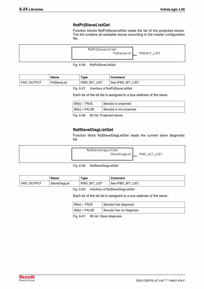
6-24 Libraries IndraLogic L40
DOK-CONTRL-IC*L40*****-AW01-EN-P
fbdPrjSlaveListGetFunction blocks fbdPrjSlaveListGet reads the list of the projected slaves.The list contains all available slaves according to the master configurationfile.
Fig. 6-56: fbdPrjSlaveListGet
Name Type Comment
VAR_OUTPUT PrjSlaveList tFBD_BIT_LIST See tFBD_BIT_LIST.
Fig. 6-57: Interface of fbdPrjSlaveListGet
Each bit of the bit list is assigned to a bus address of the slave:
Bit[x] = TRUE Slave[x] is projected
Bit[x] = FALSE Slave[x] is not projected
Fig. 6-58: Bit list: Projected slaves
fbdSlaveDiagListGetFunction block fbdSlaveDiagListGet reads the current slave diagnosticlist.
Fig. 6-59: fbdSlaveDiagListGet
Name Type Comment
VAR_OUTPUT SlaveDiagList tFBD_BIT_LIST See tFBD_BIT_LIST.
Fig. 6-60: Interface of fbdSlaveDiagListGet
Each bit of the bit list is assigned to a bus address of the slave:
Bit[x] = TRUE Slave[x] has diagnosis
Bit[x] = FALSE Slave[x] has no diagnosis
Fig. 6-61: Bit list: Slave diagnosis
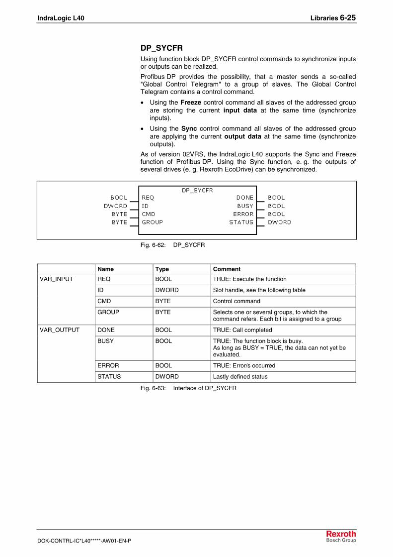
IndraLogic L40 Libraries 6-25
DOK-CONTRL-IC*L40*****-AW01-EN-P
DP_SYCFRUsing function block DP_SYCFR control commands to synchronize inputsor outputs can be realized.
Profibus DP provides the possibility, that a master sends a so-called"Global Control Telegram" to a group of slaves. The Global ControlTelegram contains a control command.
• Using the Freeze control command all slaves of the addressed groupare storing the current input data at the same time (synchronizeinputs).
• Using the Sync control command all slaves of the addressed groupare applying the current output data at the same time (synchronizeoutputs).
As of version 02VRS, the IndraLogic L40 supports the Sync and Freezefunction of Profibus DP. Using the Sync function, e. g. the outputs ofseveral drives (e. g. Rexroth EcoDrive) can be synchronized.
Fig. 6-62: DP_SYCFR
Name Type Comment
REQ BOOL TRUE: Execute the function
ID DWORD Slot handle, see the following table
CMD BYTE Control command
VAR_INPUT
GROUP BYTE Selects one or several groups, to which thecommand refers. Each bit is assigned to a group
DONE BOOL TRUE: Call completed
BUSY BOOL TRUE: The function block is busy.As long as BUSY = TRUE, the data can not yet beevaluated.
ERROR BOOL TRUE: Error/s occurred
VAR_OUTPUT
STATUS DWORD Lastly defined status
Fig. 6-63: Interface of DP_SYCFR
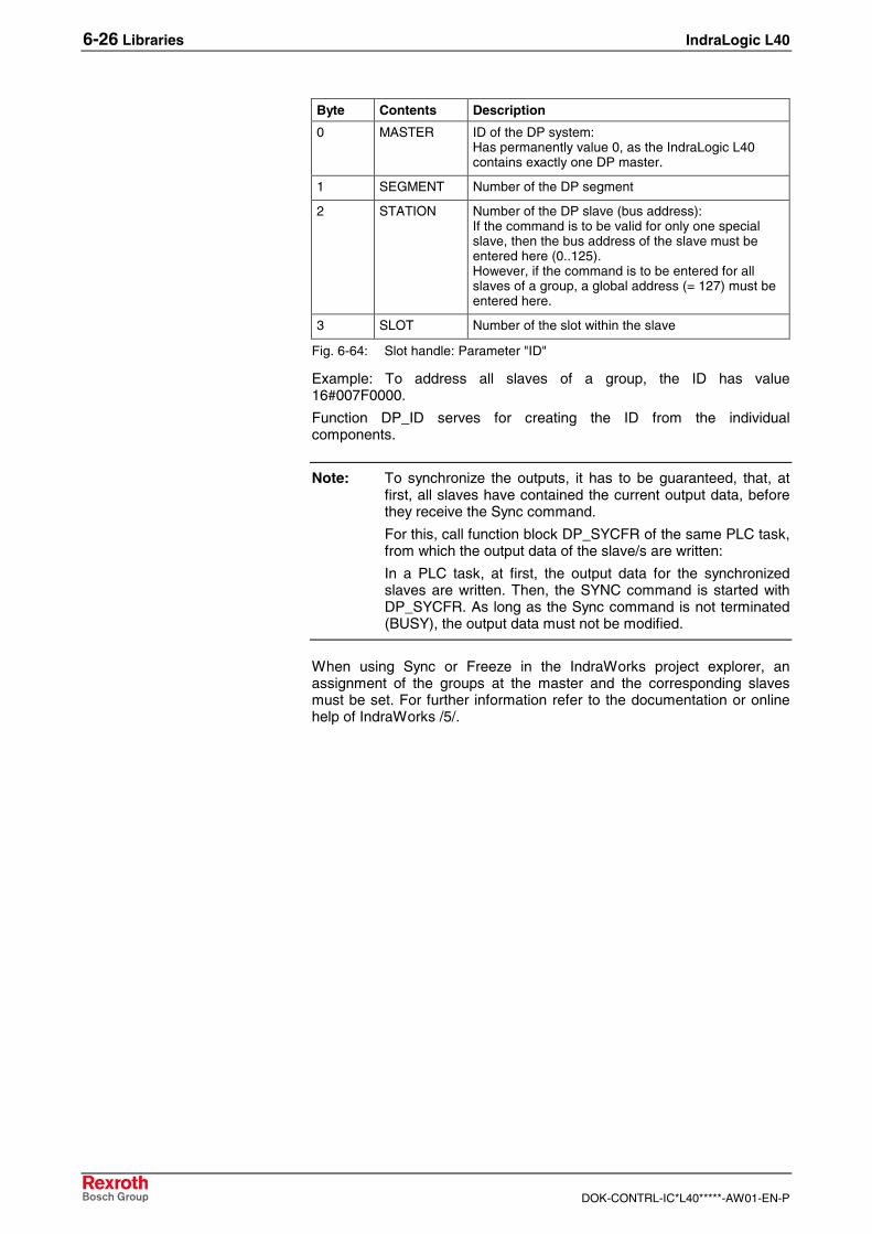
6-26 Libraries IndraLogic L40
DOK-CONTRL-IC*L40*****-AW01-EN-P
Byte Contents Description
0 MASTER ID of the DP system:Has permanently value 0, as the IndraLogic L40contains exactly one DP master.
1 SEGMENT Number of the DP segment
2 STATION Number of the DP slave (bus address):If the command is to be valid for only one specialslave, then the bus address of the slave must beentered here (0..125).However, if the command is to be entered for allslaves of a group, a global address (= 127) must beentered here.
3 SLOT Number of the slot within the slave
Fig. 6-64: Slot handle: Parameter "ID"
Example: To address all slaves of a group, the ID has value16#007F0000.
Function DP_ID serves for creating the ID from the individualcomponents.
Note: To synchronize the outputs, it has to be guaranteed, that, atfirst, all slaves have contained the current output data, beforethey receive the Sync command.
For this, call function block DP_SYCFR of the same PLC task,from which the output data of the slave/s are written:
In a PLC task, at first, the output data for the synchronizedslaves are written. Then, the SYNC command is started withDP_SYCFR. As long as the Sync command is not terminated(BUSY), the output data must not be modified.
When using Sync or Freeze in the IndraWorks project explorer, anassignment of the groups at the master and the corresponding slavesmust be set. For further information refer to the documentation or onlinehelp of IndraWorks /5/.
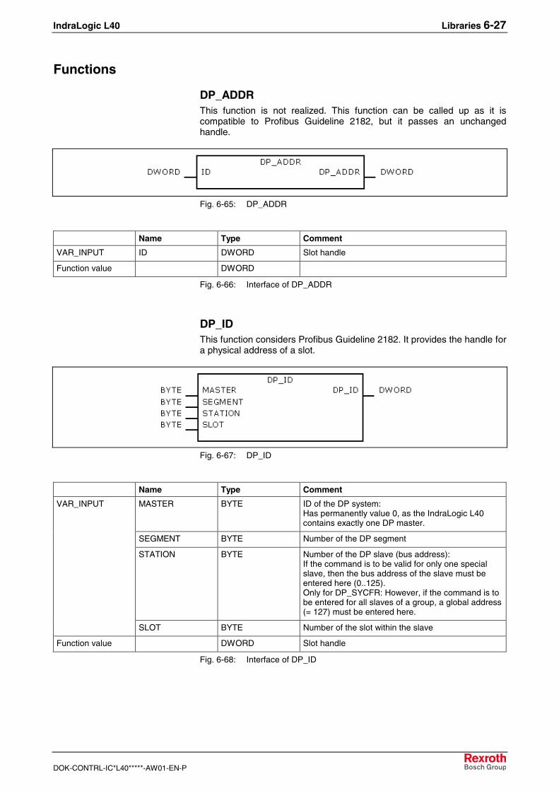
IndraLogic L40 Libraries 6-27
DOK-CONTRL-IC*L40*****-AW01-EN-P
Functions
DP_ADDRThis function is not realized. This function can be called up as it iscompatible to Profibus Guideline 2182, but it passes an unchangedhandle.
Fig. 6-65: DP_ADDR
Name Type Comment
VAR_INPUT ID DWORD Slot handle
Function value DWORD
Fig. 6-66: Interface of DP_ADDR
DP_IDThis function considers Profibus Guideline 2182. It provides the handle fora physical address of a slot.
Fig. 6-67: DP_ID
Name Type Comment
MASTER BYTE ID of the DP system:Has permanently value 0, as the IndraLogic L40contains exactly one DP master.
SEGMENT BYTE Number of the DP segment
STATION BYTE Number of the DP slave (bus address):If the command is to be valid for only one specialslave, then the bus address of the slave must beentered here (0..125).Only for DP_SYCFR: However, if the command is tobe entered for all slaves of a group, a global address(= 127) must be entered here.
VAR_INPUT
SLOT BYTE Number of the slot within the slave
Function value DWORD Slot handle
Fig. 6-68: Interface of DP_ID
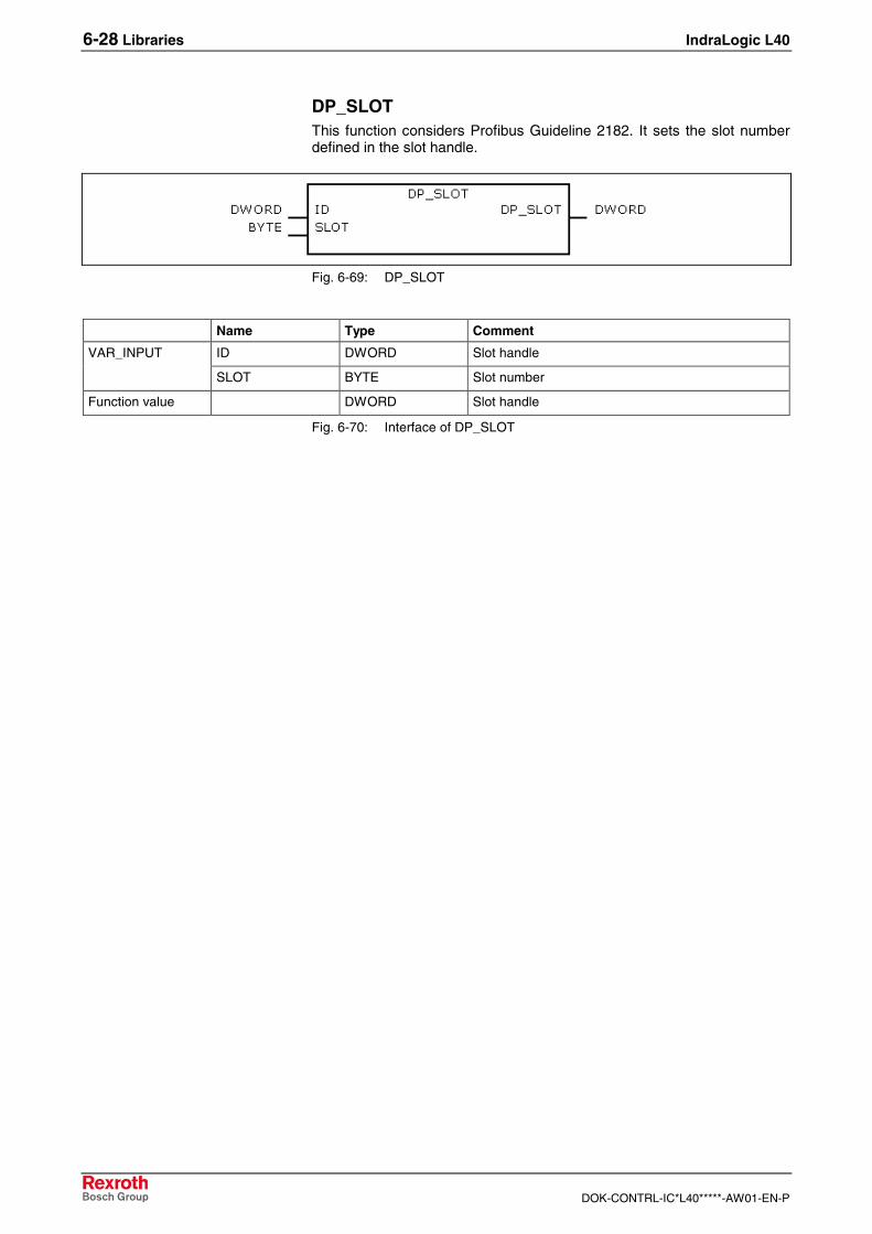
6-28 Libraries IndraLogic L40
DOK-CONTRL-IC*L40*****-AW01-EN-P
DP_SLOTThis function considers Profibus Guideline 2182. It sets the slot numberdefined in the slot handle.
Fig. 6-69: DP_SLOT
Name Type Comment
ID DWORD Slot handleVAR_INPUT
SLOT BYTE Slot number
Function value DWORD Slot handle
Fig. 6-70: Interface of DP_SLOT
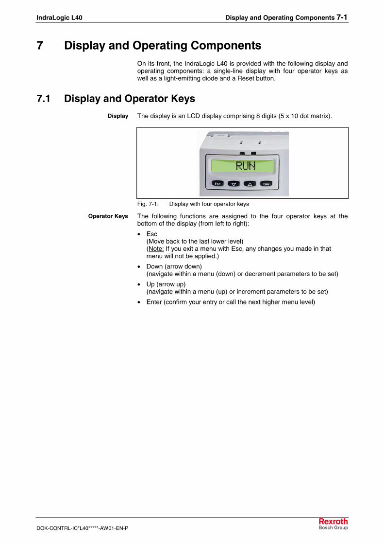
IndraLogic L40 Display and Operating Components 7-1
DOK-CONTRL-IC*L40*****-AW01-EN-P
7 Display and Operating ComponentsOn its front, the IndraLogic L40 is provided with the following display andoperating components: a single-line display with four operator keys aswell as a light-emitting diode and a Reset button.
7.1 Display and Operator Keys
The display is an LCD display comprising 8 digits (5 x 10 dot matrix).
Fig. 7-1: Display with four operator keys
The following functions are assigned to the four operator keys at thebottom of the display (from left to right):
• Esc(Move back to the last lower level)(Note: If you exit a menu with Esc, any changes you made in thatmenu will not be applied.)
• Down (arrow down)(navigate within a menu (down) or decrement parameters to be set)
• Up (arrow up)(navigate within a menu (up) or increment parameters to be set)
• Enter (confirm your entry or call the next higher menu level)
Display
Operator Keys
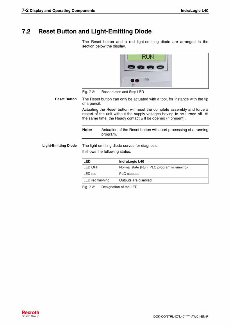
7-2 Display and Operating Components IndraLogic L40
DOK-CONTRL-IC*L40*****-AW01-EN-P
7.2 Reset Button and Light-Emitting Diode
The Reset button and a red light-emitting diode are arranged in thesection below the display.
Fig. 7-2: Reset button and Stop LED
The Reset button can only be actuated with a tool, for instance with the tipof a pencil.
Actuating the Reset button will reset the complete assembly and force arestart of the unit without the supply voltages having to be turned off. Atthe same time, the Ready contact will be opened (if present).
Note: Actuation of the Reset button will abort processing of a runningprogram.
The light emitting diode serves for diagnosis.
It shows the following states:
LED IndraLogic L40
LED OFF Normal state (Run, PLC program is running)
LED red PLC stopped
LED red flashing Outputs are disabled
Fig. 7-3: Designation of the LED
Reset Button
Light-Emitting Diode
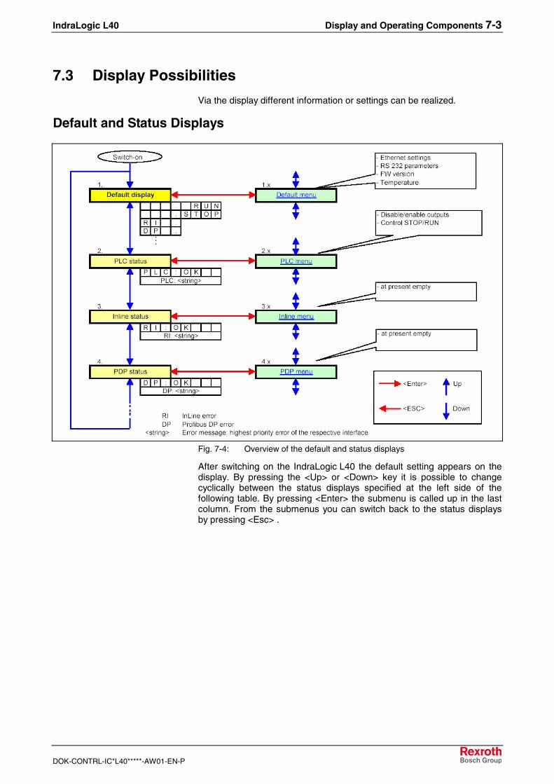
IndraLogic L40 Display and Operating Components 7-3
DOK-CONTRL-IC*L40*****-AW01-EN-P
7.3 Display Possibilities
Via the display different information or settings can be realized.
Default and Status Displays
Fig. 7-4: Overview of the default and status displays
After switching on the IndraLogic L40 the default setting appears on thedisplay. By pressing the <Up> or <Down> key it is possible to changecyclically between the status displays specified at the left side of thefollowing table. By pressing <Enter> the submenu is called up in the lastcolumn. From the submenus you can switch back to the status displaysby pressing <Esc> .
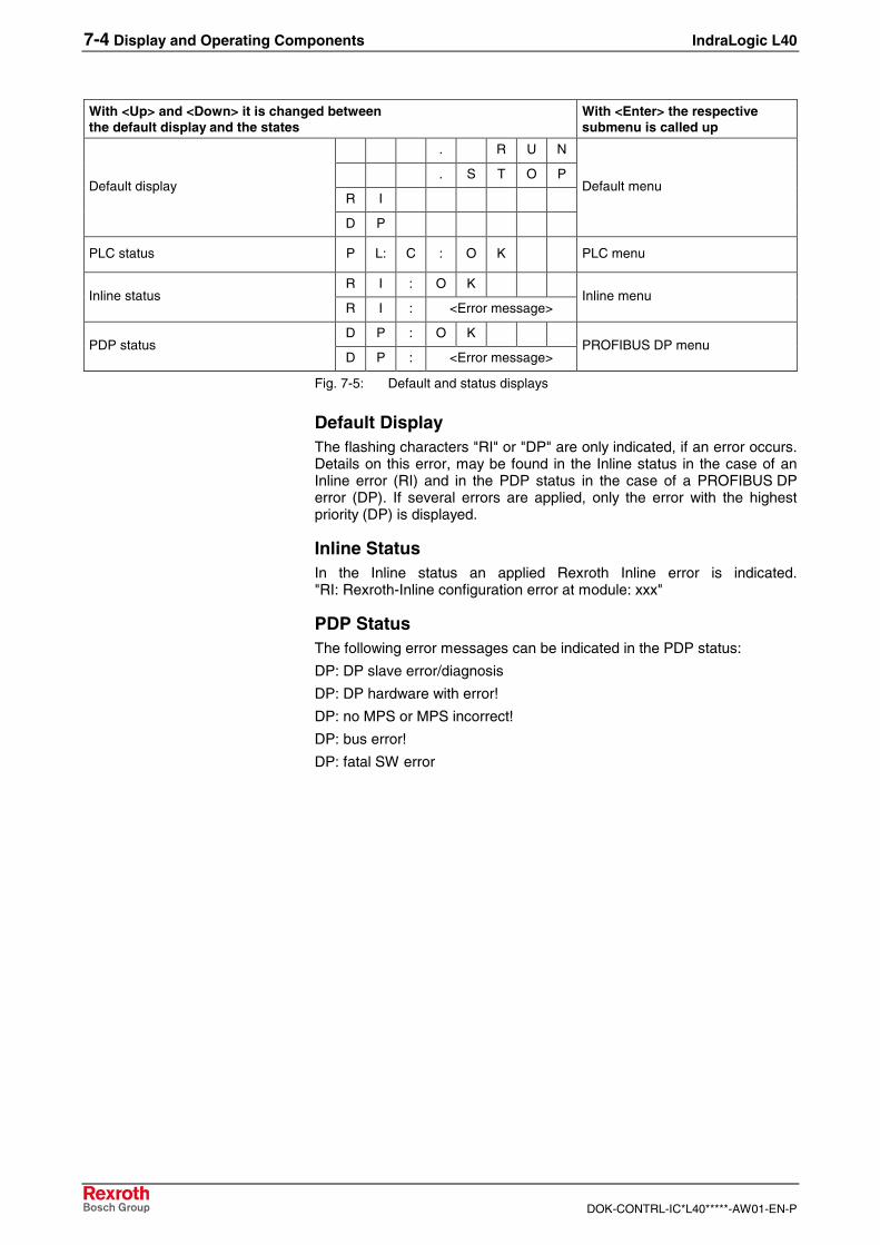
7-4 Display and Operating Components IndraLogic L40
DOK-CONTRL-IC*L40*****-AW01-EN-P
With <Up> and <Down> it is changed betweenthe default display and the states
With <Enter> the respectivesubmenu is called up
. R U N
. S T O P
R IDefault display
D P
Default menu
PLC status P L: C : O K PLC menu
R I : O KInline status
R I : <Error message>Inline menu
D P : O KPDP status
D P : <Error message>PROFIBUS DP menu
Fig. 7-5: Default and status displays
Default DisplayThe flashing characters "RI" or "DP" are only indicated, if an error occurs.Details on this error, may be found in the Inline status in the case of anInline error (RI) and in the PDP status in the case of a PROFIBUS DPerror (DP). If several errors are applied, only the error with the highestpriority (DP) is displayed.
Inline StatusIn the Inline status an applied Rexroth Inline error is indicated."RI: Rexroth-Inline configuration error at module: xxx"
PDP StatusThe following error messages can be indicated in the PDP status:
DP: DP slave error/diagnosis
DP: DP hardware with error!
DP: no MPS or MPS incorrect!
DP: bus error!
DP: fatal SW error
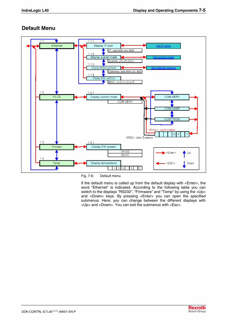
IndraLogic L40 Display and Operating Components 7-5
DOK-CONTRL-IC*L40*****-AW01-EN-P
Default Menu
Fig. 7-6: Default menu
If the default menu is called up from the default display with <Enter>, theword "Ethernet" is indicated. According to the following table you canswitch to the displays "RS232", "Firmware" and "Temp" by using the <Up>and <Down> keys. By pressing <Enter> you can open the specifiedsubmenus. Here, you can change between the different displays with<Up> and <Down>. You can exit the submenus with <Esc>.
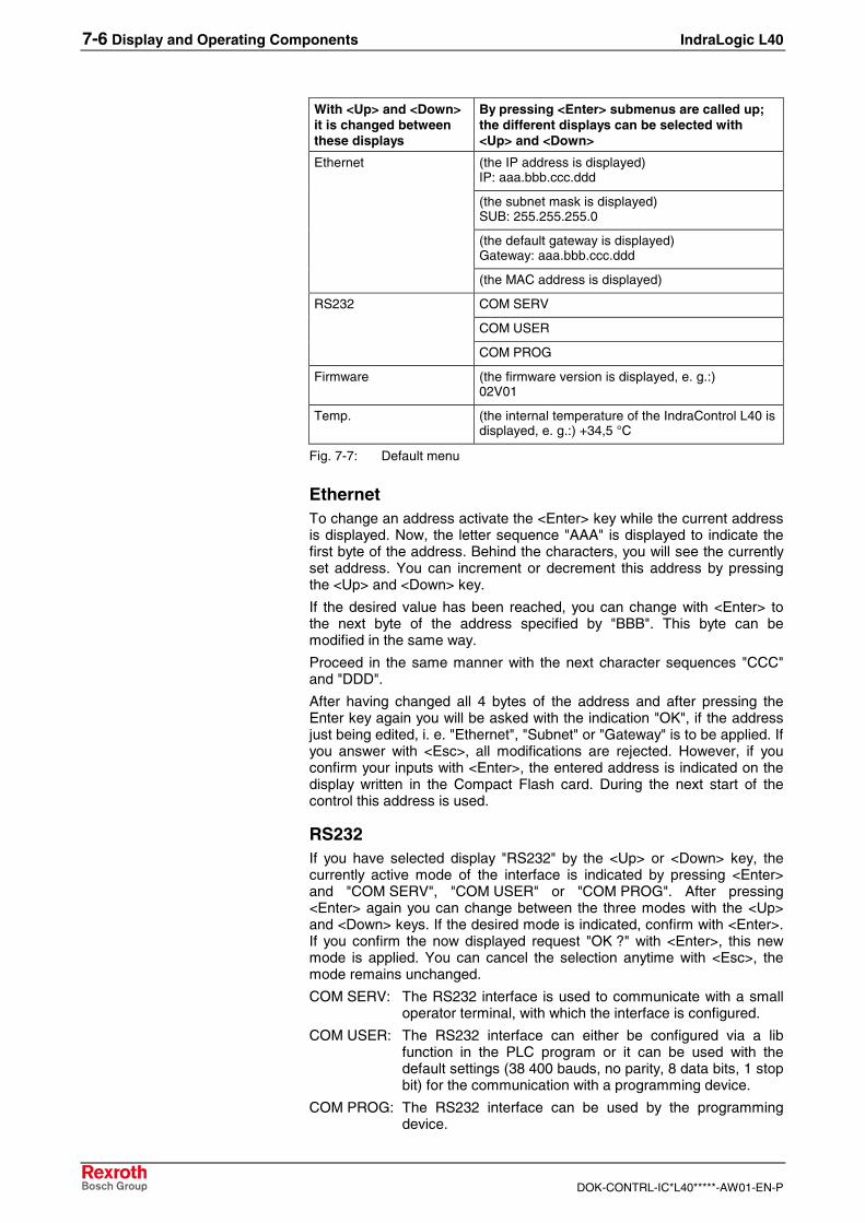
7-6 Display and Operating Components IndraLogic L40
DOK-CONTRL-IC*L40*****-AW01-EN-P
With <Up> and <Down>it is changed betweenthese displays
By pressing <Enter> submenus are called up;the different displays can be selected with<Up> and <Down>
(the IP address is displayed)IP: aaa.bbb.ccc.ddd
(the subnet mask is displayed)SUB: 255.255.255.0
(the default gateway is displayed)Gateway: aaa.bbb.ccc.ddd
Ethernet
(the MAC address is displayed)
COM SERV
COM USER
RS232
COM PROG
Firmware (the firmware version is displayed, e. g.:)02V01
Temp. (the internal temperature of the IndraControl L40 isdisplayed, e. g.:) +34,5 °C
Fig. 7-7: Default menu
EthernetTo change an address activate the <Enter> key while the current addressis displayed. Now, the letter sequence "AAA" is displayed to indicate thefirst byte of the address. Behind the characters, you will see the currentlyset address. You can increment or decrement this address by pressingthe <Up> and <Down> key.
If the desired value has been reached, you can change with <Enter> tothe next byte of the address specified by "BBB". This byte can bemodified in the same way.
Proceed in the same manner with the next character sequences "CCC"and "DDD".
After having changed all 4 bytes of the address and after pressing theEnter key again you will be asked with the indication "OK", if the addressjust being edited, i. e. "Ethernet", "Subnet" or "Gateway" is to be applied. Ifyou answer with <Esc>, all modifications are rejected. However, if youconfirm your inputs with <Enter>, the entered address is indicated on thedisplay written in the Compact Flash card. During the next start of thecontrol this address is used.
RS232If you have selected display "RS232" by the <Up> or <Down> key, thecurrently active mode of the interface is indicated by pressing <Enter>and "COM SERV", "COM USER" or "COM PROG". After pressing<Enter> again you can change between the three modes with the <Up>and <Down> keys. If the desired mode is indicated, confirm with <Enter>.If you confirm the now displayed request "OK ?" with <Enter>, this newmode is applied. You can cancel the selection anytime with <Esc>, themode remains unchanged.
COM SERV: The RS232 interface is used to communicate with a smalloperator terminal, with which the interface is configured.
COM USER: The RS232 interface can either be configured via a libfunction in the PLC program or it can be used with thedefault settings (38 400 bauds, no parity, 8 data bits, 1 stopbit) for the communication with a programming device.
COM PROG: The RS232 interface can be used by the programmingdevice.
IndraLogic L40 Display and Operating Components 7-7
DOK-CONTRL-IC*L40*****-AW01-EN-P
Note: After having changed this setting you have to deactivate andthen activate the IndraLogic L40 again, so that the settings areapplied.
FirmwareIn this submenu the version number of the installed firmware is displayed.
Temperature DisplayHere, the internal temperature of the IndraLogic L40 is indicated.
DANGER
Danger of destruction by overheating⇒ Ensure an ambient temperature of less than 45 °C.⇒ If the ambient temperature exceeds 45 °C, the
optionally available fan must be used.Also if the internal temperature exceeds 60 °C, thefan must be used.An integrated fan control with hysteresis activatesthe fan if a critical internal temperature is reached;once the temperature falls below uncritical values,the control deactivates the fan again.
⇒ If the temperature reaches a value of 75 °C, thecontrol is automatically entering a standby mode sothat damage is prevented. The outputs enter the safestatus, and the warning "Temp !!!" appears on thedisplay.
⇒ By means of a lib function, the application programcan read the internal temperature of theIndraLogic L40, in order to trigger further reactions.
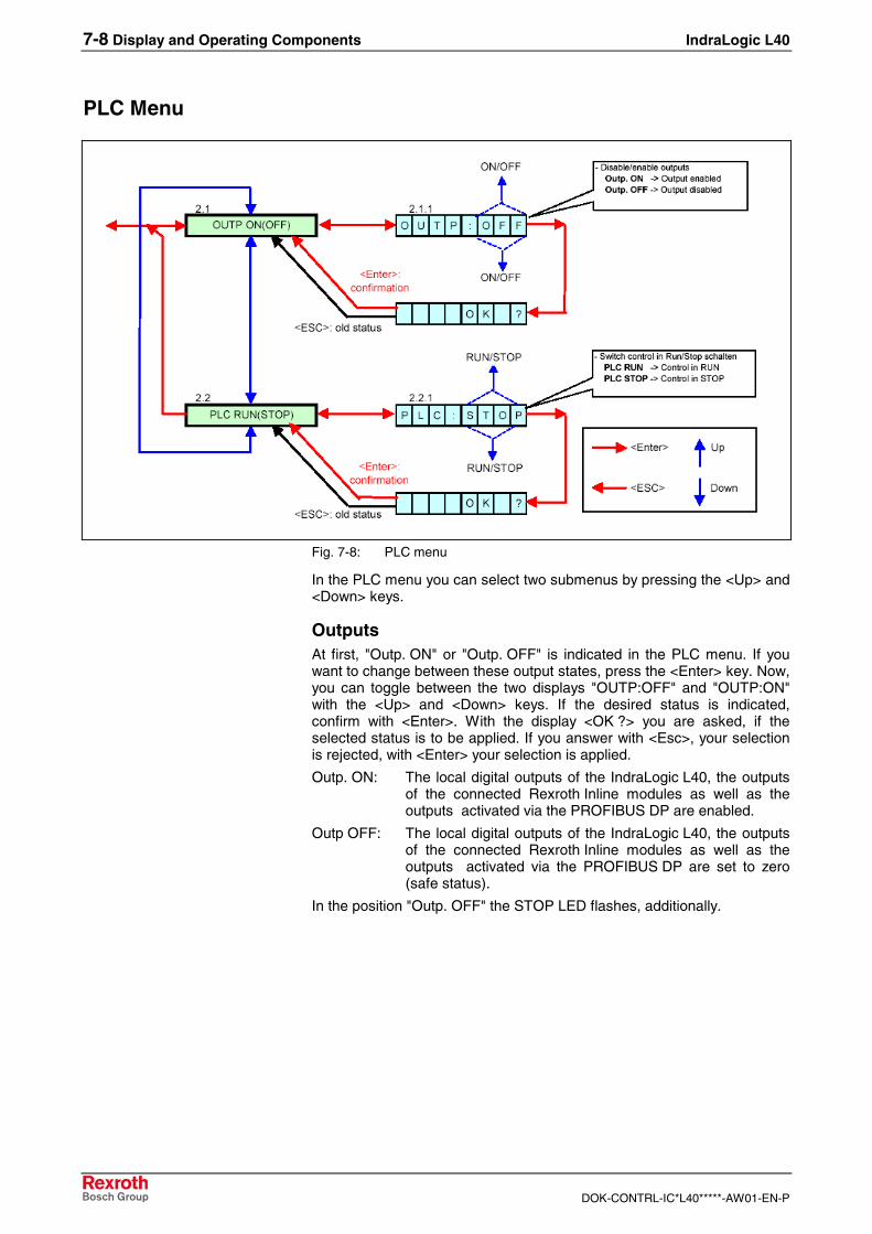
7-8 Display and Operating Components IndraLogic L40
DOK-CONTRL-IC*L40*****-AW01-EN-P
PLC Menu
Fig. 7-8: PLC menu
In the PLC menu you can select two submenus by pressing the <Up> and<Down> keys.
OutputsAt first, "Outp. ON" or "Outp. OFF" is indicated in the PLC menu. If youwant to change between these output states, press the <Enter> key. Now,you can toggle between the two displays "OUTP:OFF" and "OUTP:ON"with the <Up> and <Down> keys. If the desired status is indicated,confirm with <Enter>. With the display <OK ?> you are asked, if theselected status is to be applied. If you answer with <Esc>, your selectionis rejected, with <Enter> your selection is applied.
Outp. ON: The local digital outputs of the IndraLogic L40, the outputsof the connected Rexroth Inline modules as well as theoutputs activated via the PROFIBUS DP are enabled.
Outp OFF: The local digital outputs of the IndraLogic L40, the outputsof the connected Rexroth Inline modules as well as theoutputs activated via the PROFIBUS DP are set to zero(safe status).
In the position "Outp. OFF" the STOP LED flashes, additionally.
IndraLogic L40 Display and Operating Components 7-9
DOK-CONTRL-IC*L40*****-AW01-EN-P
PLC RUN and PLC STOPBy pressing the <Up> or <Down> key you reach a display "PLC RUN" or"PLC STOP". If you want to change between these states, press the<Enter> key. Now, you can toggle between the two displays "PLC:STOP"and "PLC:RUN" with the <Up> and <Down> keys. If the desired status isindicated, confirm with <Enter>. With the display <OK ?> you are asked, ifthe selected status is to be applied. If you answer with <Esc>, yourselection is rejected, with <Enter> your selection is applied.
PLC RUN: Activate outputs and start the PLC program.
PLC STOP: Set the outputs into the safe status and stop the PLCprogram.
Note: The same functions are activated by "Start" and "Stop" by aconnected programming device, so that e. g. the commandPLC STOP entered via the IndraLogic L40 can be canceled bythe programming device and vice versa.
Inline MenuAt present, this menu is empty.
PROFIBUS DP MenuAt present, this menu is empty.
Special CasesIf during the startup of the control the <ESC> key is pressed as long as"INIT" appears on the display, the boot project saved on the CompactFlash card is deleted corresponding to the IndraLogic function "Reset(origin).
Note: This function should only be used in exceptional cases, e. g. ifthe control does not start because of a faulty boot project.
If the control switches off because of an over-temperature, the string"TEMP !!!" is indicated.
7-10 Display and Operating Components IndraLogic L40
DOK-CONTRL-IC*L40*****-AW01-EN-P
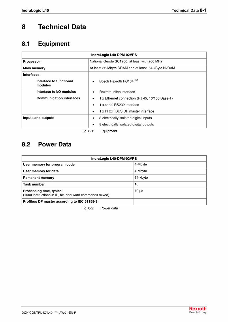
IndraLogic L40 Technical Data 8-1
DOK-CONTRL-IC*L40*****-AW01-EN-P
8 Technical Data
8.1 Equipment
IndraLogic L40-DPM-02VRS
Processor National Geode SC1200, at least with 266 MHz
Main memory At least 32-Mbyte DRAM and at least. 64-kByte NvRAM
Interfaces:
Interface to functionalmodules
• Bosch Rexroth PC104Plus
Interface to I/O modules • Rexroth Inline interface
Communication interfaces • 1 x Ethernet connection (RJ 45, 10/100 Base-T)
• 1 x serial RS232 interface
• 1 x PROFIBUS DP master interface
Inputs and outputs • 8 electrically isolated digital inputs
• 8 electrically isolated digital outputs
Fig. 8-1: Equipment
8.2 Power Data
IndraLogic L40-DPM-02VRS
User memory for program code 4-Mbyte
User memory for data 4-Mbyte
Remanent memory 64-kbyte
Task number 16
Processing time, typical(1000 instructions in IL, bit- and word commands mixed)
70 µs
Profibus DP master according to IEC 61158-3
Fig. 8-2: Power data

8-2 Technical Data IndraLogic L40
DOK-CONTRL-IC*L40*****-AW01-EN-P
IndraLogic L40 List of Figures 9-1
DOK-CONTRL-IC*L40*****-AW01-EN-P
9 List of FiguresFig. 1-1: Further documentation 1-1
Fig. 3-1: Hazard classification (according to ANSI Z535) 3-1
Fig. 4-1: Start IndraWorks 4-1
Fig. 4-2: Create new project 4-2
Fig. 4-3: Insertion of the IndraLogic L40 in the project explorer 4-2
Fig. 4-4: Example: IndraLogic L40 DPM in the project explorer 4-3
Fig. 4-5: Device Settings 4-4
Fig. 4-6: IndraLogic communication parameter 4-5
Fig. 4-7: Communication settings 4-5
Fig. 4-8: Context menu, device properties to the IndraLogic L40 4-6
Fig. 4-9: Context menu, communication properties to the IndraLogic L404-6
Fig. 4-10: Onboard I/O of the IndraLogic L40 4-7
Fig. 4-11: Project explorer "Onboard I/O" 4-7
Fig. 4-12: Address assignment of inputs and outputs 4-7
Fig. 4-13: Onboard settings of the IndraLogic L40 4-8
Fig. 4-14: Insert Inline module 4-9
Fig. 4-15: Inline I/O of the IndraLogic L40 4-10
Fig. 4-16: Master settings 4-11
Fig. 4-17: Insert Profibus DP slave 4-13
Fig. 4-18: Slave settings 4-14
Fig. 4-19: Active/Passive switch-over in the project explorer 4-15
Fig. 4-20: Insert a Profibus slave module 4-16
Fig. 4-21: Module data 4-17
Fig. 4-22: Logic node in the project explorer 4-19
Fig. 4-23: Update logic node 4-19
Fig. 4-24: IndraLogic, resources, target settings 4-20
Fig. 4-25: Target settings: Check out from the data base 4-21
Fig. 4-26: IndraLogic task configuration 4-22
Fig. 4-27: Insert further library: IndraWorks project path 4-23
Fig. 4-28: Library directory of the IndraLogic L40 target 4-23
Fig. 4-29: PLC program example 4-24
Fig. 5-1: Example for the dialog "Firmware management" 5-1
Fig. 5-2: Context menu device 5-1
Fig. 5-3: IndraLogic project: Context menu if IndraLogic is started 5-2
Fig. 6-1: Overview of IndraLogic L40 libraries 6-1
Fig. 6-2: BuepE_Client 6-2
Fig. 6-3: Interface of BuepE_Client 6-3
Fig. 6-4: Example for a BuepE_Client call 6-4
Fig. 6-5: VCP_PBS16_A4096 6-5
Fig. 6-6: Interface of VCP_PBS16_A4096 6-5
Fig. 6-7: VCP_PBS32_A4096 6-6
9-2 List of Figures IndraLogic L40
DOK-CONTRL-IC*L40*****-AW01-EN-P
Fig. 6-8: Interface of VCP_PBS32_A4096 6-6
Fig. 6-9: VCP_PBS32_A65536 6-7
Fig. 6-10: Interface of VCP_PBS32_A65536 6-7
Fig. 6-11: IL_GetStateFan 6-8
Fig. 6-12: Interface of IL_GetStateFan 6-8
Fig. 6-13: IL_GetTemp 6-8
Fig. 6-14: Interface of IL_GetTemp 6-8
Fig. 6-15: Examples for IL_GetTemp 6-9
Fig. 6-16: IL_GetTempWarning 6-9
Fig. 6-17: Interface of IL_GetTempWarning 6-9
Fig. 6-18: Slave diagnostic data 6-11
Fig. 6-19: Station status_1 6-12
Fig. 6-20: Station status_2 6-12
Fig. 6-21: Station status_3 6-13
Fig. 6-22: tFBD_BM_INFO 6-14
Fig. 6-23: Installed peripheral driver in "PdType" 6-14
Fig. 6-24: Status coding in "BmState" 6-15
Fig. 6-25: Error coding in "BmError" 6-15
Fig. 6-26: tFBD_BIT_LIST 6-16
Fig. 6-27: Coding of the bit list 6-16
Fig. 6-28: tFBD_KSD_LIST 6-16
Fig. 6-29: Classified slave diagnosis 6-17
Fig. 6-30: Coding of the bit list 6-17
Fig. 6-31: Bit list: Classified slave diagnosis 6-17
Fig. 6-32: DP_RDIAG 6-18
Fig. 6-33: Interface of DP_RDIAG 6-18
Fig. 6-34: Slot handle: Parameter "ID" 6-18
Fig. 6-35: DP_RDIAG_EXT 6-19
Fig. 6-36: Interface of DP_RDIAG_EXT 6-19
Fig. 6-37: Slot handle: Parameter "ID" 6-19
Fig. 6-38: DP_RDREC 6-20
Fig. 6-39: Interface of DP_RDREC 6-20
Fig. 6-40: Slot handle: Parameter "ID" 6-20
Fig. 6-41: DP_WRREC 6-21
Fig. 6-42: Interface of DP_WRREC 6-21
Fig. 6-43: Slot handle: Parameter "ID" 6-21
Fig. 6-44: fbdBaudrateGet 6-22
Fig. 6-45: Interface of fbdBaudrateGet 6-22
Fig. 6-46: fbdBmErrorGet 6-22
Fig. 6-47: Interface of fbdBmErrorGet 6-22
Fig. 6-48: fbdBmInfoGet 6-22
Fig. 6-49: Interface of fbdBmInfoGet 6-22
Fig. 6-50: fbdBmStateGet 6-23
Fig. 6-51: Interface of fbdBmStateGet 6-23
IndraLogic L40 List of Figures 9-3
DOK-CONTRL-IC*L40*****-AW01-EN-P
Fig. 6-52: fbdKsdListGet 6-23
Fig. 6-53: Interface of fbdKsdListGet 6-23
Fig. 6-54: fbdPdTypeGet 6-23
Fig. 6-55: Interface of fbdPdTypeGet 6-23
Fig. 6-56: fbdPrjSlaveListGet 6-24
Fig. 6-57: Interface of fbdPrjSlaveListGet 6-24
Fig. 6-58: Bit list: Projected slaves 6-24
Fig. 6-59: fbdSlaveDiagListGet 6-24
Fig. 6-60: Interface of fbdSlaveDiagListGet 6-24
Fig. 6-61: Bit list: Slave diagnosis 6-24
Fig. 6-62: DP_SYCFR 6-25
Fig. 6-63: Interface of DP_SYCFR 6-25
Fig. 6-64: Slot handle: Parameter "ID" 6-26
Fig. 6-65: DP_ADDR 6-27
Fig. 6-66: Interface of DP_ADDR 6-27
Fig. 6-67: DP_ID 6-27
Fig. 6-68: Interface of DP_ID 6-27
Fig. 6-69: DP_SLOT 6-28
Fig. 6-70: Interface of DP_SLOT 6-28
Fig. 7-1: Display with four operator keys 7-1
Fig. 7-2: Reset button and Stop LED 7-2
Fig. 7-3: Designation of the LED 7-2
Fig. 7-4: Overview of the default and status displays 7-3
Fig. 7-5: Default and status displays 7-4
Fig. 7-6: Default menu 7-5
Fig. 7-7: Default menu 7-6
Fig. 7-8: PLC menu 7-8
Fig. 8-1: Equipment 8-1
Fig. 8-2: Power data 8-1

9-4 List of Figures IndraLogic L40
DOK-CONTRL-IC*L40*****-AW01-EN-P
IndraLogic L40 Index 10-1
DOK-CONTRL-IC*L40*****-AW01-EN-P
10 Index
AAppropriate use
Introduction 2-1Uses 2-2
BBmError 6-15BMF_BUS_ERR 6-15BMF_HW_ERR 6-15BMF_MPS_ERR 6-15BMF_SW_ERR 6-15BMS_AKTIV 6-14BMS_BMF 6-14BMS_DPS 6-15BMS_EXD 6-15BMS_KSD 6-14BMS_SD 6-14BMS_SF 6-15BMS_SKF 6-15BMS_SNB 6-15BMS_SNE 6-15BmState 6-14Bosch controls of the CL range 6-2BuepE_Client 6-2Bus master error word 6-15, 6-22Bus master status word 6-14, 6-23
CCL control 6-2Classified slave diagnosis 6-17
DDiagnostic information 6-10Displays of the IndraLogic L40 7-3DP_ADDR 6-27DP_ID 6-27DP_RDIAG 6-18DP_RDIAG_EXT 6-19DP_RDREC 6-20DP_SLOT 6-28DP_SYCFR 6-25DP_WRREC 6-21DPV1 services 6-10
FfbdBaudrateGet 6-22fbdBmErrorGet 6-22fbdBmInfoGet 6-22fbdBmStateGet 6-23fbdKsdListGet 6-23fbdPdTypeGet 6-23fbdPrjSlaveListGet 6-24fbdSlaveDiagListGet 6-24Freeze 6-11Further documentation 1-1
10-2 Index IndraLogic L40
DOK-CONTRL-IC*L40*****-AW01-EN-P
IIL_GetStateFan 6-8IL_GetTemp 6-8IL_GetTempWarning 6-9IL_VCP_DP 6-5Inappropriate use 2-2
Consequences, Discharge of liability 2-1IndraControl L40 1-1IndraLogic 1-1IndraLogic L40
Commissioning 4-25Communication settings 4-4Create a PLC program 4-24Create project 4-2Display 7-1Download 4-25Equipment 8-1Field bus configuration 4-11Field bus diagnosis 6-13Firmware management 5-1Freeze 4-18Gateway server 4-4Import IndraLogic Project File 5-1Inline modules 4-9Insert modules 4-9, 4-16Insert slaves 4-13Keys 7-1Libraries 6-1Library manager 4-23Log-in 4-25Module settings 4-10Onboard I/O 4-7, 4-22Online functions 4-25Operator keys 7-1PLC configuration 4-22PLC Programming 4-19Power Data 8-1Profibus configuration 4-11Project explorer 4-2Projecting and Programming 4-1Reset button 7-2Slave Diagnosis 6-11Stop LED 7-2Sync 4-18Synchronize drives 4-18Target settings 4-20Task configuration 4-21Technical data 8-1
IndraWorks 1-1IndraWorks HMI 1-1
KKSD 6-17
PPDT_NONE 6-14, 6-23PDT_PCI_BMCAN 6-14, 6-23PDT_PCI_BMDP 6-14, 6-23PDT_PCI_BMIBS 6-14, 6-23Profibus
Diagnostic information 6-10Master 6-10Sync and freeze 6-11
IndraLogic L40 Index 10-3
DOK-CONTRL-IC*L40*****-AW01-EN-P
RRIL_L40_Util 6-8RIL_ProfibusDP 6-10
SSafety Instructions for Electric Drives and Controls 3-1Small operator terminals 6-5Sync 6-11System overview 1-1
TTarget Manager 1-1Target Support Package 1-1Target system files 1-1tFBD_BIT_LIST 6-16tFBD_BM_INFO 6-14tFBD_KSD_LIST 6-16TSP 1-1
UUse See appropriate use and inappropriate use
VVCP_PBS16_A4096 6-5VCP_PBS32_A4096 6-6VCP_PBS32_A65536 6-7VI Composer 6-5, 6-6, 6-7
WWinStudio 1-1

10-4 Index IndraLogic L40
DOK-CONTRL-IC*L40*****-AW01-EN-P
IndraLogic L40 Service & Support 11-1
DOK-CONTRL-IC*L40*****-AW01-EN-P
11 Service & Support
11.1 Helpdesk
Unser Kundendienst-Helpdesk im Hauptwerk Lohram Main steht Ihnen mit Rat und Tat zur Seite.Sie erreichen uns
Our service helpdesk at our headquarters in Lohr amMain, Germany can assist you in all kinds of inquiries.Contact us
- telefonisch - by phone: +49 (0) 9352 40 50 60über Service Call Entry Center Mo-Fr 07:00-18:00- via Service Call Entry Center Mo-Fr 7:00 am - 6:00 pm
- per Fax - by fax: +49 (0) 9352 40 49 41
- per e-Mail - by e-mail: [email protected]
11.2 Service-Hotline
Außerhalb der Helpdesk-Zeiten ist der Servicedirekt ansprechbar unter
After helpdesk hours, contact our servicedepartment directly at
+49 (0) 171 333 88 26
oder - or +49 (0) 172 660 04 06
11.3 Internet
Unter www.boschrexroth.com finden Sieergänzende Hinweise zu Service, Reparatur undTraining sowie die aktuellen Adressen *) unsererauf den folgenden Seiten aufgeführten Vertriebs-und Servicebüros.
Verkaufsniederlassungen
Niederlassungen mit Kundendienst
Außerhalb Deutschlands nehmen Sie bitte zuerst Kontakt mitunserem für Sie nächstgelegenen Ansprechpartner auf.
*) Die Angaben in der vorliegenden Dokumentation könnenseit Drucklegung überholt sein.
At www.boschrexroth.com you may findadditional notes about service, repairs and trainingin the Internet, as well as the actual addresses *)of our sales- and service facilities figuring on thefollowing pages.
sales agencies
offices providing service
Please contact our sales / service office in your area first.
*) Data in the present documentation may have becomeobsolete since printing.
11.4 Vor der Kontaktaufnahme... - Before contacting us...
Wir können Ihnen schnell und effizient helfen wennSie folgende Informationen bereithalten:
1. detaillierte Beschreibung der Störung und derUmstände.
2. Angaben auf dem Typenschild derbetreffenden Produkte, insbesondereTypenschlüssel und Seriennummern.
3. Tel.-/Faxnummern und e-Mail-Adresse, unterdenen Sie für Rückfragen zu erreichen sind.
For quick and efficient help, please have thefollowing information ready:
1. Detailed description of the failure andcircumstances.
2. Information on the type plate of the affectedproducts, especially type codes and serialnumbers.
3. Your phone/fax numbers and e-mail address,so we can contact you in case of questions.
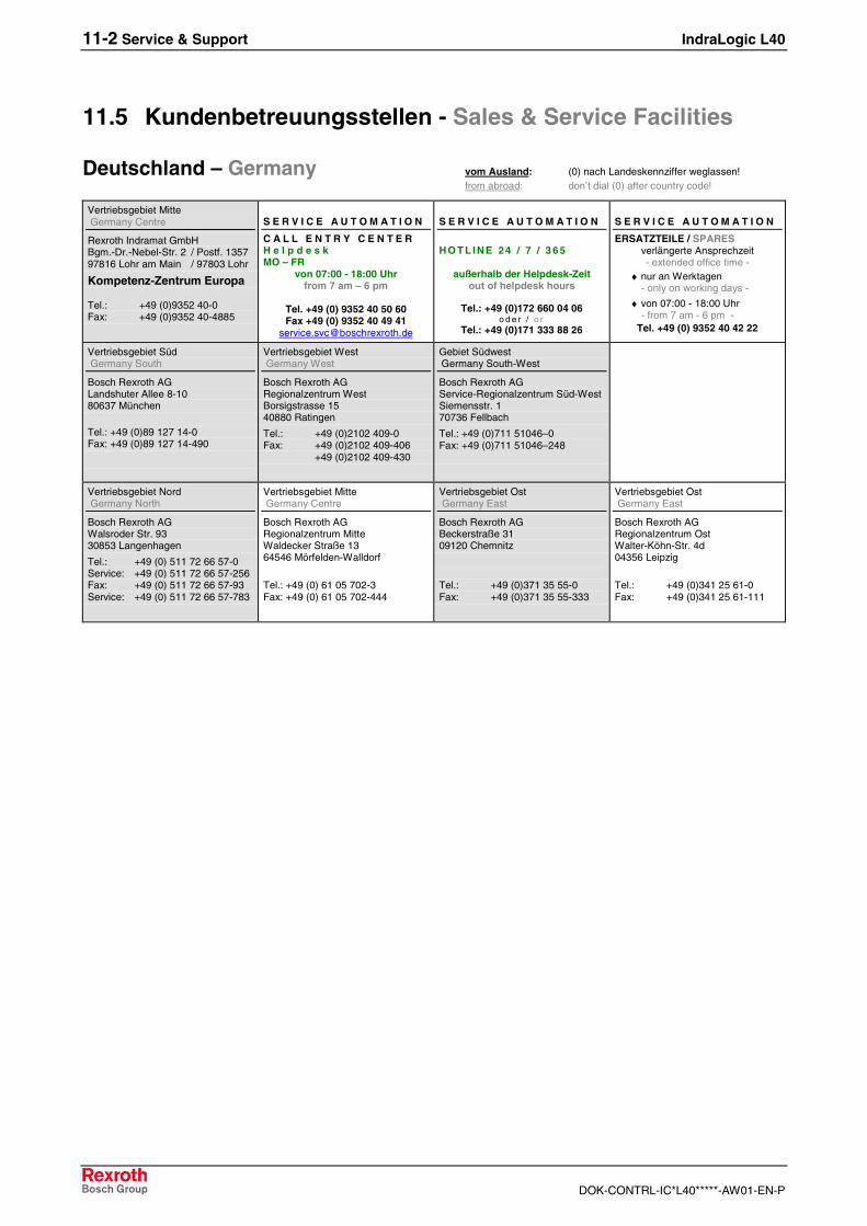
11-2 Service & Support IndraLogic L40
DOK-CONTRL-IC*L40*****-AW01-EN-P
11.5 Kundenbetreuungsstellen - Sales & Service Facilities
Deutschland – Germany vom Ausland: (0) nach Landeskennziffer weglassen!from abroad: don’t dial (0) after country code!
Vertriebsgebiet Mitte Germany Centre
Rexroth Indramat GmbHBgm.-Dr.-Nebel-Str. 2 / Postf. 135797816 Lohr am Main / 97803 Lohr
Kompetenz-Zentrum Europa
Tel.: +49 (0)9352 40-0Fax: +49 (0)9352 40-4885
S E R V I C E A U T O M A T I O N
C A L L E N T R Y C E N T E RH e l p d e s kMO – FR
von 07:00 - 18:00 Uhrfrom 7 am – 6 pm
Tel. +49 (0) 9352 40 50 60Fax +49 (0) 9352 40 49 41
S E R V I C E A U T O M A T I O N
HO T L INE 24 / 7 / 3 6 5
außerhalb der Helpdesk-Zeitout of helpdesk hours
Tel.: +49 (0)172 660 04 06o d e r / o r
Tel.: +49 (0)171 333 88 26
S E R V I C E A U T O M A T I O N
ERSATZTEILE / SPARESverlängerte Ansprechzeit- extended office time -
♦ nur an Werktagen- only on working days -
♦ von 07:00 - 18:00 Uhr- from 7 am - 6 pm -
Tel. +49 (0) 9352 40 42 22
Vertriebsgebiet Süd Germany South
Bosch Rexroth AGLandshuter Allee 8-1080637 München
Tel.: +49 (0)89 127 14-0Fax: +49 (0)89 127 14-490
Vertriebsgebiet West Germany West
Bosch Rexroth AGRegionalzentrum WestBorsigstrasse 1540880 Ratingen
Tel.: +49 (0)2102 409-0Fax: +49 (0)2102 409-406
+49 (0)2102 409-430
Gebiet Südwest Germany South-West
Bosch Rexroth AGService-Regionalzentrum Süd-WestSiemensstr. 170736 Fellbach
Tel.: +49 (0)711 51046–0Fax: +49 (0)711 51046–248
Vertriebsgebiet Nord Germany North
Bosch Rexroth AGWalsroder Str. 9330853 Langenhagen
Tel.: +49 (0) 511 72 66 57-0Service: +49 (0) 511 72 66 57-256Fax: +49 (0) 511 72 66 57-93Service: +49 (0) 511 72 66 57-783
Vertriebsgebiet Mitte Germany Centre
Bosch Rexroth AGRegionalzentrum MitteWaldecker Straße 1364546 Mörfelden-Walldorf
Tel.: +49 (0) 61 05 702-3Fax: +49 (0) 61 05 702-444
Vertriebsgebiet Ost Germany East
Bosch Rexroth AGBeckerstraße 3109120 Chemnitz
Tel.: +49 (0)371 35 55-0Fax: +49 (0)371 35 55-333
Vertriebsgebiet Ost Germany East
Bosch Rexroth AGRegionalzentrum OstWalter-Köhn-Str. 4d04356 Leipzig
Tel.: +49 (0)341 25 61-0Fax: +49 (0)341 25 61-111
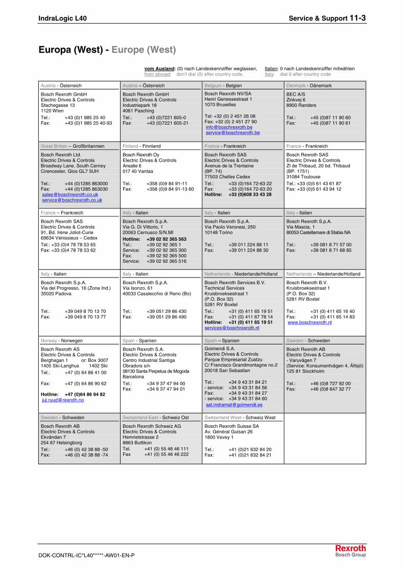
IndraLogic L40 Service & Support 11-3
DOK-CONTRL-IC*L40*****-AW01-EN-P
Europa (West) - Europe (West)
vom Ausland: (0) nach Landeskennziffer weglassen, Italien: 0 nach Landeskennziffer mitwählenfrom abroad: don’t dial (0) after country code, Italy: dial 0 after country code
Austria - Österreich
Bosch Rexroth GmbHElectric Drives & ControlsStachegasse 131120 Wien
Tel.: +43 (0)1 985 25 40Fax: +43 (0)1 985 25 40-93
Austria – Österreich
Bosch Rexroth GmbHElectric Drives & ControlsIndustriepark 184061 Pasching
Tel.: +43 (0)7221 605-0Fax: +43 (0)7221 605-21
Belgium - Belgien
Bosch Rexroth NV/SAHenri Genessestraat 11070 Bruxelles
Tel: +32 (0) 2 451 26 08Fax: +32 (0) 2 451 27 90 [email protected] [email protected]
Denmark - Dänemark
BEC A/SZinkvej 68900 Randers
Tel.: +45 (0)87 11 90 60Fax: +45 (0)87 11 90 61
Great Britain – Großbritannien
Bosch Rexroth Ltd.Electric Drives & ControlsBroadway Lane, South CerneyCirencester, Glos GL7 5UH
Tel.: +44 (0)1285 863000Fax: +44 (0)1285 863030 [email protected] [email protected]
Finland - Finnland
Bosch Rexroth OyElectric Drives & ControlsAnsatie 6017 40 Vantaa
Tel.: +358 (0)9 84 91-11Fax: +358 (0)9 84 91-13 60
France - Frankreich
Bosch Rexroth SASElectric Drives & ControlsAvenue de la Trentaine(BP. 74)77503 Chelles Cedex
Tel.: +33 (0)164 72-63 22Fax: +33 (0)164 72-63 20Hotline: +33 (0)608 33 43 28
France - Frankreich
Bosch Rexroth SASElectric Drives & ControlsZI de Thibaud, 20 bd. Thibaud(BP. 1751)31084 Toulouse
Tel.: +33 (0)5 61 43 61 87Fax: +33 (0)5 61 43 94 12
France – Frankreich
Bosch Rexroth SASElectric Drives & Controls91, Bd. Irène Joliot-Curie69634 Vénissieux – CedexTel.: +33 (0)4 78 78 53 65Fax: +33 (0)4 78 78 53 62
Italy - Italien
Bosch Rexroth S.p.A.Via G. Di Vittorio, 120063 Cernusco S/N.MIHotline: +39 02 92 365 563Tel.: +39 02 92 365 1Service: +39 02 92 365 300Fax: +39 02 92 365 500Service: +39 02 92 365 516
Italy - Italien
Bosch Rexroth S.p.A.Via Paolo Veronesi, 25010148 Torino
Tel.: +39 011 224 88 11Fax: +39 011 224 88 30
Italy - Italien
Bosch Rexroth S.p.A.Via Mascia, 180053 Castellamare di Stabia NA
Tel.: +39 081 8 71 57 00Fax: +39 081 8 71 68 85
Italy - Italien
Bosch Rexroth S.p.A.Via del Progresso, 16 (Zona Ind.)35020 Padova
Tel.: +39 049 8 70 13 70Fax: +39 049 8 70 13 77
Italy - Italien
Bosch Rexroth S.p.A.Via Isonzo, 6140033 Casalecchio di Reno (Bo)
Tel.: +39 051 29 86 430Fax: +39 051 29 86 490
Netherlands - Niederlande/Holland
Bosch Rexroth Services B.V.Technical ServicesKruisbroeksestraat 1(P.O. Box 32)5281 RV BoxtelTel.: +31 (0) 411 65 19 51Fax: +31 (0) 411 67 78 14Hotline: +31 (0) 411 65 19 [email protected]
Netherlands – Niederlande/Holland
Bosch Rexroth B.V.Kruisbroeksestraat 1(P.O. Box 32)5281 RV Boxtel
Tel.: +31 (0) 411 65 16 40Fax: +31 (0) 411 65 14 83 www.boschrexroth.nl
Norway - Norwegen
Bosch Rexroth ASElectric Drives & ControlsBerghagan 1 or: Box 30071405 Ski-Langhus 1402 SkiTel.: +47 (0) 64 86 41 00
Fax: +47 (0) 64 86 90 62
Hotline: +47 (0)64 86 94 82 [email protected]
Spain - Spanien
Bosch Rexroth S.A.Electric Drives & ControlsCentro Industrial SantigaObradors s/n08130 Santa Perpetua de MogodaBarcelona
Tel.: +34 9 37 47 94 00Fax: +34 9 37 47 94 01
Spain – Spanien
Goimendi S.A.Electric Drives & ControlsParque Empresarial ZuatzuC/ Francisco Grandmontagne no.220018 San Sebastian
Tel.: +34 9 43 31 84 21- service: +34 9 43 31 84 56Fax: +34 9 43 31 84 27- service: +34 9 43 31 84 60 [email protected]
Sweden - Schweden
Bosch Rexroth ABElectric Drives & Controls- Varuvägen 7(Service: Konsumentvägen 4, Älfsjö)125 81 Stockholm
Tel.: +46 (0)8 727 92 00Fax: +46 (0)8 647 32 77
Sweden - Schweden
Bosch Rexroth ABElectric Drives & ControlsEkvändan 7254 67 HelsingborgTel.: +46 (0) 42 38 88 -50Fax: +46 (0) 42 38 88 -74
Switzerland East - Schweiz Ost
Bosch Rexroth Schweiz AGElectric Drives & ControlsHemrietstrasse 28863 ButtikonTel. +41 (0) 55 46 46 111Fax +41 (0) 55 46 46 222
Switzerland West - Schweiz West
Bosch Rexroth Suisse SAAv. Général Guisan 261800 Vevey 1
Tel.: +41 (0)21 632 84 20Fax: +41 (0)21 632 84 21
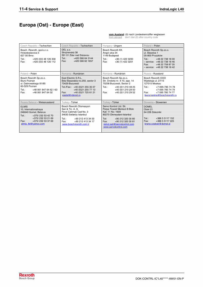
11-4 Service & Support IndraLogic L40
DOK-CONTRL-IC*L40*****-AW01-EN-P
Europa (Ost) - Europe (East)
vom Ausland: (0) nach Landeskennziffer weglassen from abroad: don’t dial (0) after country code
Czech Republic - Tschechien
Bosch -Rexroth, spol.s.r.o.Hviezdoslavova 5627 00 Brno
Tel.: +420 (0)5 48 126 358Fax: +420 (0)5 48 126 112
Czech Republic - Tschechien
DEL a.s.Strojírenská 38591 01 Zdar nad SázavouTel.: +420 566 64 3144Fax: +420 566 62 1657
Hungary - Ungarn
Bosch Rexroth Kft.Angol utca 341149 Budapest
Tel.: +36 (1) 422 3200Fax: +36 (1) 422 3201
Poland – Polen
Bosch Rexroth Sp.zo.o.ul. Staszica 105-800 Pruszków
Tel.: +48 22 738 18 00– service: +48 22 738 18 46Fax: +48 22 758 87 35– service: +48 22 738 18 42
Poland – Polen
Bosch Rexroth Sp.zo.o.Biuro Poznanul. Dabrowskiego 81/8560-529 Poznan
Tel.: +48 061 847 64 62 /-63Fax: +48 061 847 64 02
Romania - Rumänien
East Electric S.R.L.Bdul Basarabia no.250, sector 373429 Bucuresti
Tel./Fax:: +40 (0)21 255 35 07+40 (0)21 255 77 13
Fax: +40 (0)21 725 61 21 [email protected]
Romania - Rumänien
Bosch Rexroth Sp.zo.o.Str. Drobety nr. 4-10, app. 1470258 Bucuresti, Sector 2
Tel.: +40 (0)1 210 48 25+40 (0)1 210 29 50
Fax: +40 (0)1 210 29 52
Russia - Russland
Bosch Rexroth OOOWjatskaja ul. 27/15127015 Moskau
Tel.: +7-095-785 74 78+7-095 785 74 79
Fax: +7 095 785 74 77 [email protected]
Russia Belarus - Weissrussland
ELMIS10, Internationalnaya246640 Gomel, BelarusTel.: +375/ 232 53 42 70
+375/ 232 53 21 69Fax: +375/ 232 53 37 69 [email protected]
Turkey - Türkei
Bosch Rexroth OtomasyonSan & Tic. A..S.Fevzi Cakmak Cad No. 334630 Sefaköy Istanbul
Tel.: +90 212 413 34 00Fax: +90 212 413 34 17 www.boschrexroth.com.tr
Turkey - Türkei
Servo Kontrol Ltd. Sti.Perpa Ticaret Merkezi B BlokKat: 11 No: 160980270 Okmeydani-Istanbul
Tel: +90 212 320 30 80Fax: +90 212 320 30 81 [email protected] www.servokontrol.com
Slowenia - Slowenien
DOMELOtoki 2164 228 Zelezniki
Tel.: +386 5 5117 152Fax: +386 5 5117 225 [email protected]
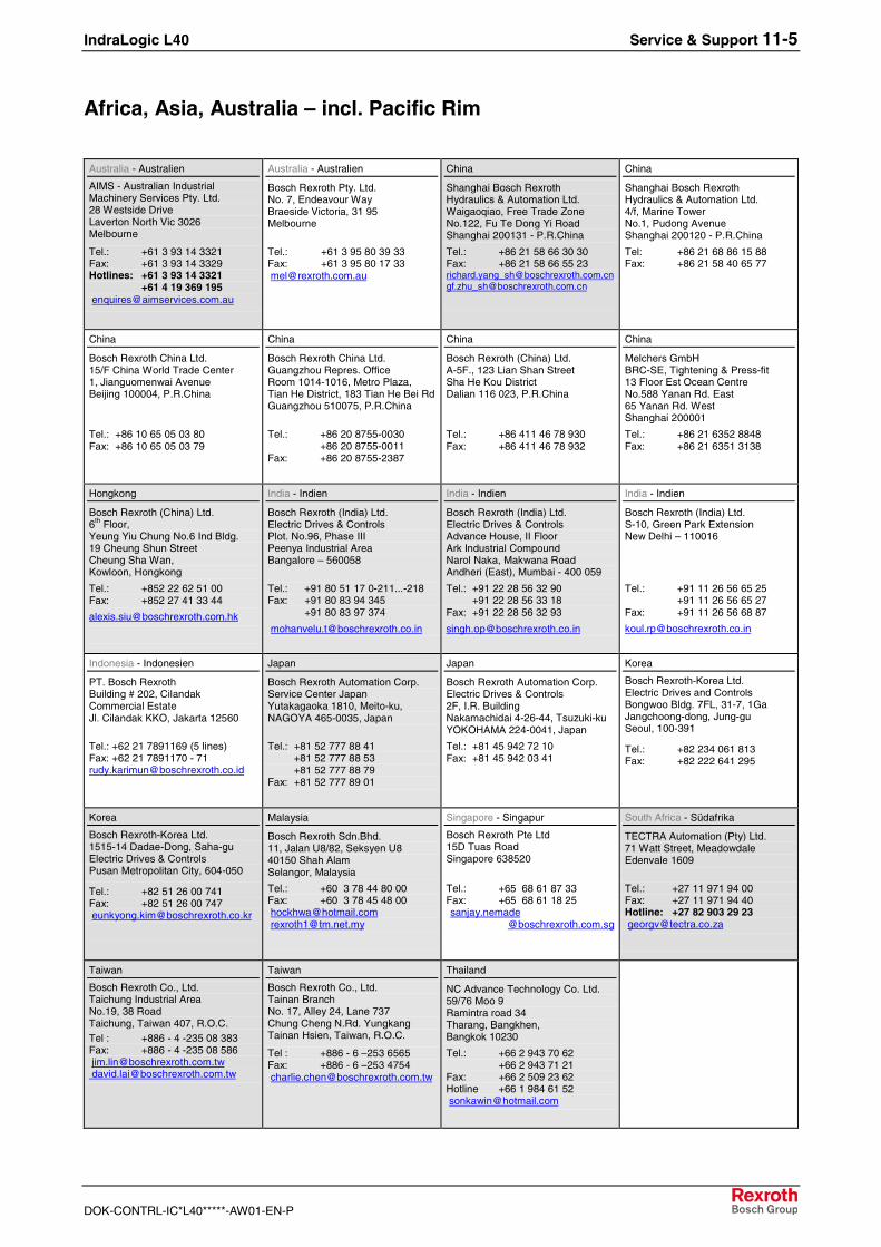
IndraLogic L40 Service & Support 11-5
DOK-CONTRL-IC*L40*****-AW01-EN-P
Africa, Asia, Australia – incl. Pacific Rim
Australia - Australien
AIMS - Australian IndustrialMachinery Services Pty. Ltd.28 Westside DriveLaverton North Vic 3026Melbourne
Tel.: +61 3 93 14 3321Fax: +61 3 93 14 3329Hotlines: +61 3 93 14 3321
+61 4 19 369 195 [email protected]
Australia - Australien
Bosch Rexroth Pty. Ltd.No. 7, Endeavour WayBraeside Victoria, 31 95Melbourne
Tel.: +61 3 95 80 39 33Fax: +61 3 95 80 17 33 [email protected]
China
Shanghai Bosch RexrothHydraulics & Automation Ltd.Waigaoqiao, Free Trade ZoneNo.122, Fu Te Dong Yi RoadShanghai 200131 - P.R.China
Tel.: +86 21 58 66 30 30Fax: +86 21 58 66 55 [email protected][email protected]
China
Shanghai Bosch RexrothHydraulics & Automation Ltd.4/f, Marine TowerNo.1, Pudong AvenueShanghai 200120 - P.R.China
Tel: +86 21 68 86 15 88Fax: +86 21 58 40 65 77
China
Bosch Rexroth China Ltd.15/F China World Trade Center1, Jianguomenwai AvenueBeijing 100004, P.R.China
Tel.: +86 10 65 05 03 80Fax: +86 10 65 05 03 79
China
Bosch Rexroth China Ltd.Guangzhou Repres. OfficeRoom 1014-1016, Metro Plaza,Tian He District, 183 Tian He Bei RdGuangzhou 510075, P.R.China
Tel.: +86 20 8755-0030+86 20 8755-0011
Fax: +86 20 8755-2387
China
Bosch Rexroth (China) Ltd.A-5F., 123 Lian Shan StreetSha He Kou DistrictDalian 116 023, P.R.China
Tel.: +86 411 46 78 930Fax: +86 411 46 78 932
China
Melchers GmbHBRC-SE, Tightening & Press-fit13 Floor Est Ocean CentreNo.588 Yanan Rd. East65 Yanan Rd. WestShanghai 200001
Tel.: +86 21 6352 8848Fax: +86 21 6351 3138
Hongkong
Bosch Rexroth (China) Ltd.6th Floor,Yeung Yiu Chung No.6 Ind Bldg.19 Cheung Shun StreetCheung Sha Wan,Kowloon, Hongkong
Tel.: +852 22 62 51 00Fax: +852 27 41 33 44
India - Indien
Bosch Rexroth (India) Ltd.Electric Drives & ControlsPlot. No.96, Phase IIIPeenya Industrial AreaBangalore – 560058
Tel.: +91 80 51 17 0-211...-218Fax: +91 80 83 94 345
+91 80 83 97 374
India - Indien
Bosch Rexroth (India) Ltd.Electric Drives & ControlsAdvance House, II FloorArk Industrial CompoundNarol Naka, Makwana RoadAndheri (East), Mumbai - 400 059
Tel.: +91 22 28 56 32 90+91 22 28 56 33 18
Fax: +91 22 28 56 32 93
India - Indien
Bosch Rexroth (India) Ltd.S-10, Green Park ExtensionNew Delhi – 110016
Tel.: +91 11 26 56 65 25+91 11 26 56 65 27
Fax: +91 11 26 56 68 87
Indonesia - Indonesien
PT. Bosch RexrothBuilding # 202, CilandakCommercial EstateJl. Cilandak KKO, Jakarta 12560
Tel.: +62 21 7891169 (5 lines)Fax: +62 21 7891170 - [email protected]
Japan
Bosch Rexroth Automation Corp.Service Center JapanYutakagaoka 1810, Meito-ku,NAGOYA 465-0035, Japan
Tel.: +81 52 777 88 41+81 52 777 88 53+81 52 777 88 79
Fax: +81 52 777 89 01
Japan
Bosch Rexroth Automation Corp.Electric Drives & Controls2F, I.R. BuildingNakamachidai 4-26-44, Tsuzuki-kuYOKOHAMA 224-0041, Japan
Tel.: +81 45 942 72 10Fax: +81 45 942 03 41
Korea
Bosch Rexroth-Korea Ltd.Electric Drives and ControlsBongwoo Bldg. 7FL, 31-7, 1GaJangchoong-dong, Jung-guSeoul, 100-391
Tel.: +82 234 061 813Fax: +82 222 641 295
Korea
Bosch Rexroth-Korea Ltd.1515-14 Dadae-Dong, Saha-guElectric Drives & ControlsPusan Metropolitan City, 604-050
Tel.: +82 51 26 00 741Fax: +82 51 26 00 747 [email protected]
Malaysia
Bosch Rexroth Sdn.Bhd.11, Jalan U8/82, Seksyen U840150 Shah AlamSelangor, Malaysia
Tel.: +60 3 78 44 80 00Fax: +60 3 78 45 48 00 [email protected] [email protected]
Singapore - Singapur
Bosch Rexroth Pte Ltd15D Tuas RoadSingapore 638520
Tel.: +65 68 61 87 33Fax: +65 68 61 18 25 sanjay.nemade
@boschrexroth.com.sg
South Africa - Südafrika
TECTRA Automation (Pty) Ltd.71 Watt Street, MeadowdaleEdenvale 1609
Tel.: +27 11 971 94 00Fax: +27 11 971 94 40Hotline: +27 82 903 29 23 [email protected]
Taiwan
Bosch Rexroth Co., Ltd.Taichung Industrial AreaNo.19, 38 RoadTaichung, Taiwan 407, R.O.C.Tel : +886 - 4 -235 08 383Fax: +886 - 4 -235 08 586 [email protected] [email protected]
Taiwan
Bosch Rexroth Co., Ltd.Tainan BranchNo. 17, Alley 24, Lane 737Chung Cheng N.Rd. YungkangTainan Hsien, Taiwan, R.O.C.
Tel : +886 - 6 –253 6565Fax: +886 - 6 –253 4754 [email protected]
Thailand
NC Advance Technology Co. Ltd.59/76 Moo 9Ramintra road 34Tharang, Bangkhen,Bangkok 10230
Tel.: +66 2 943 70 62 +66 2 943 71 21Fax: +66 2 509 23 62Hotline +66 1 984 61 52 [email protected]
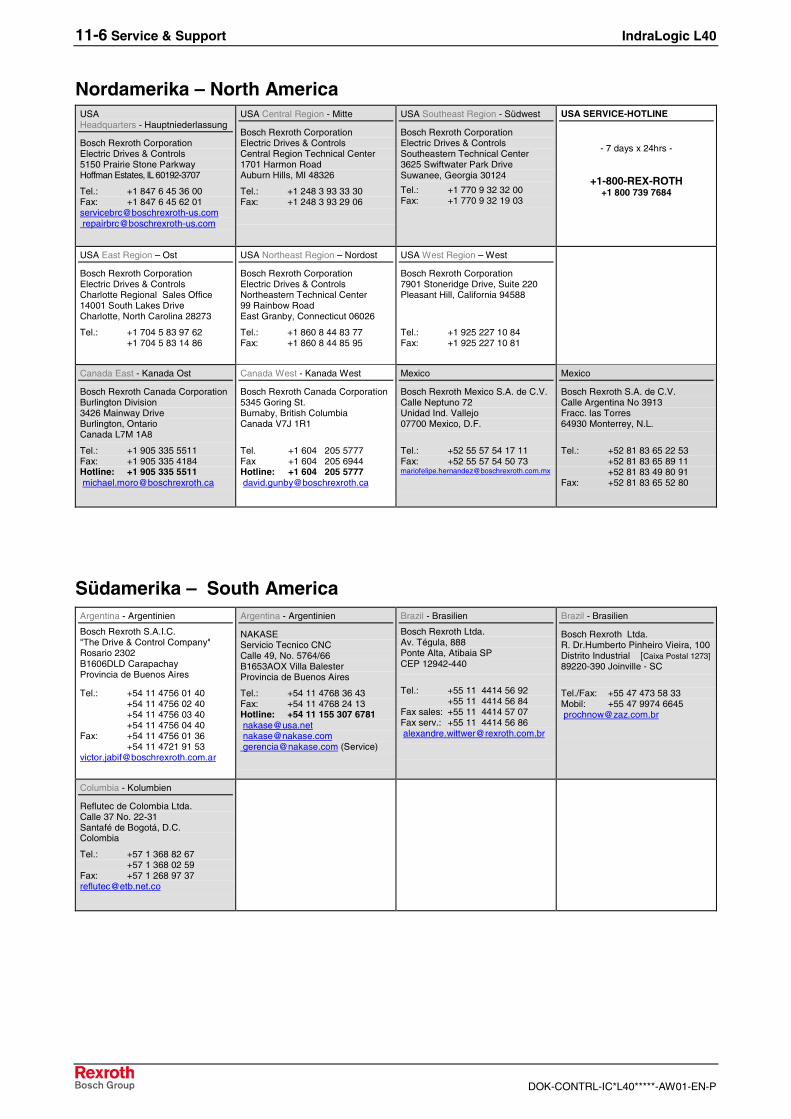
11-6 Service & Support IndraLogic L40
DOK-CONTRL-IC*L40*****-AW01-EN-P
Nordamerika – North AmericaUSAHeadquarters - Hauptniederlassung
Bosch Rexroth CorporationElectric Drives & Controls5150 Prairie Stone ParkwayHoffman Estates, IL 60192-3707
Tel.: +1 847 6 45 36 00Fax: +1 847 6 45 62 [email protected] [email protected]
USA Central Region - Mitte
Bosch Rexroth CorporationElectric Drives & ControlsCentral Region Technical Center1701 Harmon RoadAuburn Hills, MI 48326
Tel.: +1 248 3 93 33 30Fax: +1 248 3 93 29 06
USA Southeast Region - Südwest
Bosch Rexroth CorporationElectric Drives & ControlsSoutheastern Technical Center3625 Swiftwater Park DriveSuwanee, Georgia 30124
Tel.: +1 770 9 32 32 00Fax: +1 770 9 32 19 03
USA SERVICE-HOTLINE
- 7 days x 24hrs -
+1-800-REX-ROTH+1 800 739 7684
USA East Region – Ost
Bosch Rexroth CorporationElectric Drives & ControlsCharlotte Regional Sales Office14001 South Lakes DriveCharlotte, North Carolina 28273
Tel.: +1 704 5 83 97 62+1 704 5 83 14 86
USA Northeast Region – Nordost
Bosch Rexroth CorporationElectric Drives & ControlsNortheastern Technical Center99 Rainbow RoadEast Granby, Connecticut 06026
Tel.: +1 860 8 44 83 77Fax: +1 860 8 44 85 95
USA West Region – West
Bosch Rexroth Corporation7901 Stoneridge Drive, Suite 220Pleasant Hill, California 94588
Tel.: +1 925 227 10 84Fax: +1 925 227 10 81
Canada East - Kanada Ost
Bosch Rexroth Canada CorporationBurlington Division3426 Mainway DriveBurlington, OntarioCanada L7M 1A8
Tel.: +1 905 335 5511Fax: +1 905 335 4184Hotline: +1 905 335 5511 [email protected]
Canada West - Kanada West
Bosch Rexroth Canada Corporation5345 Goring St.Burnaby, British ColumbiaCanada V7J 1R1
Tel. +1 604 205 5777Fax +1 604 205 6944Hotline: +1 604 205 5777 [email protected]
Mexico
Bosch Rexroth Mexico S.A. de C.V.Calle Neptuno 72Unidad Ind. Vallejo07700 Mexico, D.F.
Tel.: +52 55 57 54 17 11Fax: +52 55 57 54 50 [email protected]
Mexico
Bosch Rexroth S.A. de C.V.Calle Argentina No 3913Fracc. las Torres64930 Monterrey, N.L.
Tel.: +52 81 83 65 22 53+52 81 83 65 89 11+52 81 83 49 80 91
Fax: +52 81 83 65 52 80
Südamerika – South AmericaArgentina - Argentinien
Bosch Rexroth S.A.I.C."The Drive & Control Company"Rosario 2302B1606DLD CarapachayProvincia de Buenos Aires
Tel.: +54 11 4756 01 40+54 11 4756 02 40+54 11 4756 03 40+54 11 4756 04 40
Fax: +54 11 4756 01 36+54 11 4721 91 53
Argentina - Argentinien
NAKASEServicio Tecnico CNCCalle 49, No. 5764/66B1653AOX Villa BalesterProvincia de Buenos Aires
Tel.: +54 11 4768 36 43Fax: +54 11 4768 24 13Hotline: +54 11 155 307 6781 [email protected] [email protected] [email protected] (Service)
Brazil - Brasilien
Bosch Rexroth Ltda.Av. Tégula, 888Ponte Alta, Atibaia SPCEP 12942-440
Tel.: +55 11 4414 56 92+55 11 4414 56 84
Fax sales: +55 11 4414 57 07Fax serv.: +55 11 4414 56 86 [email protected]
Brazil - Brasilien
Bosch Rexroth Ltda.R. Dr.Humberto Pinheiro Vieira, 100Distrito Industrial [Caixa Postal 1273]89220-390 Joinville - SC
Tel./Fax: +55 47 473 58 33Mobil: +55 47 9974 6645 [email protected]
Columbia - Kolumbien
Reflutec de Colombia Ltda.Calle 37 No. 22-31Santafé de Bogotá, D.C.Colombia
Tel.: +57 1 368 82 67+57 1 368 02 59
Fax: +57 1 268 97 [email protected]


Bosch Rexroth AGElectric Drives and ControlsP.O. Box 13 5797803 Lohr, GermanyBgm.-Dr.-Nebel-Str. 297816 Lohr, GermanyPhone +49 (0)93 52-40-50 60Fax +49 (0)93 52-40-49 [email protected]
Printed in GermanyDOK-CONTRL-IC*L40*****-AW01-EN-PR911309372