rfcd 202: introduction to w-cdmabbs.hwrf.com.cn/downpeef/w-cdma介绍.pdf · page: 2 benefits of...
TRANSCRIPT

Page: 1
RFCD 202: Introduction to W-CDMA
Technical data is subject to changeCopyright@2003 Agilent Technologies’Printed on Dec. 4, 2002 5988-8504ENA
This paper examines the core concepts of one operating mode of the IMT-2000 world wide system: 3GPP WCDMA. This system is based on the WCDMA system developed in Japan and Europe. While this standard is a part of the harmonized worldwide standard, it will continue to be developed by the 3GPP standards body that originally developed it. This paper covers the standard as found in the Release 99 version completed in December 1999. A number of features of the 3GPP system have been omitted in the Release 99 standard in order to meet the time schedule. These omitted features, as well as new services, will be added in a second release of the standard to be completed at the end of 2000.The physical aspects of the air interface are examined as well as enough of the upper protocol layers required to gain a general understanding of the system’s operating principles. This paper assumes that the reader has a basic understanding of the principles of direct sequence, spread spectrum communications.

Page: 2
Benefits of 3GPP WCDMA
Higher Capacity - about 2X IS-95, 7X GSMAbility to Send up to 384 kbps High Speed Data while Moving (Internet, video, multimedia, etc.)
Up to 2 Mbps Throughput for Fixed Applications5 MHz Bandwidth is more Immune to FadingNo Accurate Base Station Synchronization NeededSupport for Hand-off To and From GSM
The 3GPP system is seen as the next generation replacement for PDC in Japan and for GSM in many parts of the world. 3GPP WCDMA offers much greater capacity for voice relative to either PDC or GSM. In addition, it supports packet data at all of the rates required to meet the IMT-2000 goals. This will allow many next generation applications to come to the markets currently served by GSM and PDC. One unique feature of 3GPP WCDMA is that it requires no special synchronization between cells. Most other direct spread CDMA systems require synchronization to operate (usually relying on GSP satellite timing information to synchronize each cell in the system). 3GPP’s unsynchronized nature makes placing base stations in underground subways, inside buildings, and in tunnels much simpler. To aid in the transition from GSM, the 3GPP system provides for handoffs between GSM and 3GPP. Thus, dual mode phones will allow users to freely roam between the large areas covered by GSM and new 3GPP coverage areas.

Page: 3
3GPP Frame StructurePhysical Channels Have a Two Layer Structure:
• Radio frame: 10 ms frame consisting of 15 timeslots• Timeslot: 667 usec slot consisting of a number of Symbols
Symbols are Defined as:• One Symbol Consists of a Number of Chips .• The Number of Chips per Coded Symbol is Equal to the Spread Factor of the Physical
Channel• Chip is a Bit at the Final Spreading Rate of 3.84 Mchips/s
The frame structure for 3GPP is based on the concept of Super frames, which consist of 72, 10 ms radio frames. Each radio frame is further broken down into 15, 667 usec timeslots. Each timeslot is composed of a number of symbols which varies according to the type of service used. A symbol consists of a variable number of chips. The number of chips per symbol is equal to the spreading factor for that channel. For example, a low rate service has 256 chips per symbol which means that the spreading factor is 256 times. A chip, in direct sequence, spread spectrum system is defined as the bit period at the final spreading rate. For the 3GPP system, the final spreading rate is fixed to 3,840,000 chips per second. Thus a chip for the 3GPP system has a period of .26042 micro seconds.
Page: 4
3GPP Timing OptionsThe 3GPP System has Two Timing Modes:
• Asynchronous Operation - Original Mode• GPS Synchronized - Added after Harmonization
Asynchronous Mode:• Eliminates need for GPS Satellite Receivers• Allows Operation in Tunnels, Buildings, and Subways Where Satellite Reception is Difficult• Requires Greater Search Time, More Difficult Handoffs
GPS Synchronized Mode:• Simpler, Faster Searching to Ease Soft Handoffs• Requires Base Station to Receive GPS Satellite Signals
As mentioned earlier, the 3GPP system operates in an unsynchronized mode. However, after global harmonization, an optional second timing mode was added: GPS synchronized operation. The synchronized mode of operation will allow 3GPP WCDMA to be smoothly implemented in those locations that currently use the TIA/EIA-95B CDMA system (GPS synchronized). The accurate synchronization of the GPS locked mode allows mobiles and base stations to search over short, well known time intervals when acquiring signals. This lowers the processing requirements in the mobile stations and reduces the complexity of soft handoffs. However, to achieve this synchronization, the GPS satellite system (or some other method) must be used as the master timing source. This requires that each base station must have a clear line-of-sight antenna to the GPS satellites. However, when operating the in asynchronous mode, the 3GPP system has no such requirement. This does make system access more difficult and increases search time. Great effort has been applied to the 3GPP system to reduce these effects. The benefits of asynchronous mode are: it eliminates the cost of the GPS receiver, and it eliminates the requirement that the base station be physically located so that GPS satellite reception is possible. The asynchronous mode allows simple installations is such location as tunnels and subways where GPS satellite reception is problematic.

Page: 5
Network Layer
Data Link Layer
Physical Layer
Layer 3RRC
Medium Access Control
Layer 2
Layer 1
Transport Channels
Logical Channels
MAC
RLCRadio Link Control
Physical Channels
Radio Resource Control
3GPP Protocol Structure
The protocol structure of the 3GPP system closely follows the industry standard 7 layer model. The Network Layer (Layer 3) is responsible for connecting services from the Network to User Equipment. The Radio Resource Control (RRC) block at layer three handles the connection, configuration and release of bearer services and the required corresponding radio resources. The data Link Layer (Layer 2) is composed of two main functional blocks: the Radio Link Control (RLC) and Medium Access Control (MAC) blocks. The RLC block is responsible for: transfer of user data, error correction, flow control, protocol error detection and recovery, and ciphering. The error correction function of the RLC includes such functions as Selective Repeat and Go-Back-N retransmission for lost data. The Ciphering function uses encryption technology to prevent unwanted interception of transmitted data. The MAC function at layer 2 is responsible for mapping between logical channels and transport channels as well as providing the multiplexing/de-multiplexing function of various logical channels efficiently onto the same transport channel. The Physical Layer (Layer 1) maps the transport channels on to the physical channels and performs all of the RF functions necessary to make the system work. These functions includes such operations as: frequency and time synchronization, rate matching, spreading and modulation, power control, and soft handoff.

Page: 6
3GPP Network SupportDesigned to Work with Two Networks:
• MAP Network:• GSM Network
• ANSI-41 Network:• U.S. Standard
Required to Produce a 3G “World Phone”
One of the outcomes of the harmonization efforts was the incorporation of two different network options. These two network options are the MAP network used in many GSM systems, and the ANSI-41 Network commonly used in North America. The dual network option was adopted to allow the future manufacture of “world phones”. The Release 99 version of the standard only supports the MAP network option. A future release will define the ANSI-41 option that will allow future 3GPP phones to roam from Europe or the Far East to the Americas. Given the pressure to rollout the individual systems around the world, the dual network 3GPP phone may not be produced for quite some time.

Page: 7
Sent Over the Air
Multiplexing
Physical Channel
TransportChannel 1
TransportChannel 2
TransportChannel 3
UpperLayers
Transport vs. Physical Channels
3GPP Supports the Concept of Multiple Services Sharing a Physical Connection
The Concept of “Transport” Channels is used to Support these Services
Adds an Extra Layer Where Transport Channel are Multiplexed together Prior to Transmission on a Physical Channel
The 3GPP system introduces the concept of “transport” channels to support sharing physical resources between multiple services. Each service, such as data, fax, voice, or signaling are routed into different transport channels by the upper signaling layers. These services may have different data rates and error control mechanisms. These transport channels are then multiplexed as required prior to transmission via one or more physical channels. High data rate services or a combination of lower rates transport channels may be multiplexed into several physical channels. This flexibility allows numerous transport channels (services) of varying data rates to be efficiently allocated to physical channels. By multiplexing these transport channels efficiently, system capacity is optimized. For example, if the aggregate data rate of three transport channels exceeds the maximum of a single physical channel, then the data can be routed to two lower rate physical channels that closely match the total required data rate.

Page: 8
Downlink Physical ChannelsCPICH (Common Pilot Channel). P-CCPCH (Primary Common Control Physical Channel).S-CCPCH (Secondary Common Control Physical Chan). SCH (Synchronization Channel). DPCH (Dedicated Physical Channel).PDSCH (Physical Downlink Shared Channel).AICH (Acquisition Indication Channel).PICH (Page Indication Channel).
The 3GPP downlink is composed of a number of physical channels. The Common Pilot Channel (CPICH) is used as a timing and frequency reference by mobile stations. The Primary Common Control Physical Channel (P-CCPCH) carries a transport channel called the Broadcast Channel (BCH). The BCH carries the system overhead information. The Secondary Common Control Physical Channel (S-CCPCH) can carry the Forward Access Channel or the Paging Channel (FACH or PCH, both of which are transport channels). To aid mobile synchronization to the network, each base station also transmits the Sync Channel (SCH). The main building block of the downlink is the Dedicated Physical Channel (DPCH) that carries the Dedicated Channel (DCH, which is a transport channel). The DPCH is composed of two sub-channels: the Dedicated Physical Data Channel (DPDCH) and the Dedicated Physical Control Channel (DPCCH). Other downlink channels include the Physical Downlink Shared Channel (PDSCH) which can carry information to multiple mobiles at the same time. The Acquisition Indication Channel (AICH) is used to indicate to a mobile that the base station has acquired the mobile’s attempt to contact the network. The Page Indication Channel (PICH) informs mobiles when pages directed to that mobile will be sent in an future Paging Channel slot.

Page: 9
Pilot Structure3GPP Uses Two Types of Pilot Channels:
• Code Based Pilot (CPICH - Common Pilot Channel)• Used To Broadcast Timing Information to All Mobile Stations Operating in a Cell or Sector
• Embedded Pilot Signals:• Some Downlink Channels also Included Embedded Pilot Information• Pilot Data is Time Multiplexed into the Channel• Used by Mobiles to Send Timing Information to Base Stations
After harmonization, the 3GPP WCDMA system has adopted two types of pilot channel structures: the code based pilot channel and the embedded pilot channel. In the downlink, the 3GPP system uses a single common pilot channel (CPICH) that is assigned a unique spreading code. This allows all mobiles in that cell to decode the pilot channel and use it as a timing reference. The 3GPP system also uses an embedded pilot in some of the downlink physical channels. The pilot consists of a known pattern of data bits that is multiplexed into the channel’s data stream. This known pattern can then be decoded by the receiver and used as an additional timing reference signal. Depending upon the structure of a given physical channel, the number of pilot channel data bits per frame changes. The CPICH allows mobile stations to use coherent detection to increase demodulation performance.

Page: 10
Downlink CPICHCommon Pilot Channels (CPICH):
• Primary CPICH:• Modulated with 1+j pattern• Always Uses the 256 bit OVSF Spreading Code 0• Always Uses the Cell’s Primary Scrambling Code• One Per Cell and is Broadcast Over the Entire Cell
• Secondary CPICH:• Same as the Primary CPICH Except -• Assigned Arbitrary 256 bit OVSF Spreading Code• Can use the Primary or a Secondary Scrambling Code• There can be Any Number of Them
The downlink uses a Common Pilot Channel (CPICH) to send timing information to mobile stations. Mobile stations use the pilot data to maintain synchronization with the base station and as a coherent reference to perform synchronous demodulation. The 3GPP WCDMA system has several types of Common Pilot Channels. Every cell has one and only one Primary CPICH. This channel is unmodulated (1+j pattern on the I and Q channels) and is spread with a 256 bit OVSF code that is fixed: all cells use the same 256 bit code - which is code number 0 (more on OVSF codes in a minute). The Primary CPICH is always scrambled by the base station’s primary scrambling code.A Secondary CPICH is similar to a Primary CPICH except that they are free to be assigned any 256 bit OOVSF spreading code and can use either the primary or any of the secondary scrambling codes for the associated base station. There can be any number of SecondaryCPICHs. The primary use of the Secondary CPICH will be in the future when beam formed antennas are implemented. These beam formed antennas will transmit base station signals to individual mobile stations to reduce overall interference levels while maintaining a quality link. Beam formed reception antennas will allow base stations to track the location a mobile to maintain signal quality. In these cases, a secondary CPICH channel is needed so that the mobile station can decode the beam formed signal that is directed to it.

Page: 11
Downlink P-CCPCHThe P-CCPCH (Primary Common Control Physical Channel) Transmits the BCH (Broadcast Channel) Transport Channel.
Sends Cell Information.Rate Is Fixed to 27 kbps.Broadcast over the Entire Cell.The P-CCPCH Does Not Contain Pilot, Power Control, or Rate Information.
Every Cell Uses OVSF Code 1 (256 bit).
The P-CCPCH physical channel carries the BCH transport channel. The BCH transmits cell specific information that mobiles need to communicate with the network. The BCH is always fixed to a data rate of 27 ksps. The P-CCPCH is transmitted to the entire cell or sector. The P-CCPCH is always spread with the same 256 bit OVSF code - which is code 1.
Page: 12
P-CCPCHData
18 bits
OFF
2 bits
One Timeslot = 667 usec
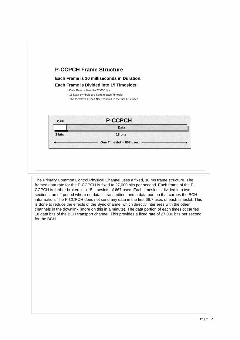
P-CCPCH Frame StructureEach Frame is 10 milliseconds in Duration.Each Frame is Divided into 15 Timeslots:
• Data Rate is Fixed to 27,000 bps• 18 Data symbols are Sent in each Timeslot• The P-CCPCH Does Not Transmit in the first 66.7 usec
The Primary Common Control Physical Channel uses a fixed, 10 ms frame structure. The framed data rate for the P-CCPCH is fixed to 27,000 bits per second. Each frame of the P-CCPCH is further broken into 15 timeslots of 667 usec. Each timeslot is divided into two sections: an off period where no data is transmitted, and a data portion that carries the BCH information. The P-CCPCH does not send any data in the first 66.7 usec of each timeslot. This is done to reduce the effects of the Sync channel which directly interferes with the other channels in the downlink (more on this in a minute). The data portion of each timeslot carries 18 data bits of the BCH transport channel. This provides a fixed rate of 27,000 bits per second for the BCH.

Page: 13
BCH Block
Repeated Data
Channel Coding
1/2 Conv. Encoder
Rate Matching
96 Data Bits 12 Bits
CRC8 Bits
Tail12 Bits
SFN
96 Data Bits
BCH Transport Block
9.6 kbps
12.8 kbps
25.6 kbps
27 kbps
256 Data Bits
256 Data Bits 14 Bits
Interleaving 270 Data Bits 27 kbps10 ms Frame
P-CCPCH Channel Coding
The channel coding of the P-CCPCH begins with a block of data from the BCH transport channel. This block of data carries the actual message portion of the BCH (system information). Several other data blocks are added to the BCH data. First, the System Frame Number (SFN) is carried by 12 bits of data. The SFN is used by the mobile to align data received from various cells during soft handoff. A twelve bit CRC is also added to allow the mobile to verify the received data. Eight tail bits are also added to reset the initial state of theconvolutional encoder to all zeroes so as to be ready for the next frame of data. At this point, the combined data is passed through a one-half rate convolutional encoder that doubles the data rate to 25.6 kbps. Rate matching is performed to bring the final rate up to 27 kbps.

Page: 14
Downlink Sync ChannelThe Primary SCH is:
• An unmodulated, 256 bit Gold Code • The Code is Sent at the Beginning of each Timeslot • All Base Station use the Same, 256 bit Gold Code
The Secondary SCH is:• A Sequence of 15, unmodulated, 256 bit Gold Codes• The Pattern is Sent using the first 256 bits of each Timeslot (15 )• The Pattern of Codes (64 total) correspond to the Scrambling Code (Long Code) Group
being used by the Base Station
Both Channels are Orthogonal to Each Other, but are NOT Orthogonal to the Other Channels.
The Synchronization channel is composed of two individual channels: the Primary SCH and Secondary SCH. The purpose of these two channels is to: provide an indentifying signal for each base station, and as a timing reference for each base station. The Primary Sync transmits an unmodulated, 256 bit Gold Code pattern at the 3.84 Mcps rate. The 256 bits are sent once in the first 10% of each timeslot (256 bits at 3.84 Mcps = 66.7 usec, each timeslot is 667 usec). This Gold code is the same for every base station. Mobiles search for this pattern when looking for suitable base stations to use. The Secondary Sync channel provides a “hint” to the mobile of which scramble code the base station is using. Instead of using a single 256 bit code, the Secondary Sync uses a specific sequence of 15, 256 bit codes in each frame. There are 64 patterns of codes for the Secondary Sync channel. The pattern used by the Secondary Sync channel indicates the scramble code group that the base station is using. In each scramble code group, there are 8 possible scramble codes. Once the mobile reads the Secondary Sync channel and determines the pattern it is using, the mobile then searches for the primary scramble code from the indicated group. It is important to realize that the Primary and Secondary Sync channels are orthogonal to each other, but are not orthogonal to the other channels in the cell.

Page: 15
One Frame = 10 ms
Primary Sync: Sends same Code in each Slot
One Timeslot = 667 usec
Slot 0 Slot 1 Slot 2 Slot 3 Slot 4 Slot 5 Slot 6 Slot 7 Slot 8 Slot 9 Slot 10 Slot 11 Slot 12 Slot 13 Slot 14
Secondary Sync: Sends a Pattern of Codes in each Frame
Code 1 Code1 Code 2 Code 8 Code 9 Code 10 Code 15 Code 8 Code 10 Code 16 Code 2 Code 7 Code 15 Code 7 Code 16
This Pattern of 256 bit Codes is Scrambling Group 1
Slot 0 Slot 1 Slot 2 Slot 3 Slot 4 Slot 5 Slot 6 Slot 7 Slot 8 Slot 9 Slot 10 Slot 11 Slot 12 Slot 13 Slot 14
Sync Frame Structure
For each 10 ms frame, both the Primary and Secondary Sync channels only transmit in the first 10% of each of the 15 timeslots. The codes sent by these two channels are taken from a set of 256 bit long codes. The Primary Sync channel sends the same 256 bit code in each timeslot. Every base station uses the same 256 bit code for the Primary Sync Channel. The Secondary Sync channel sends a pattern of 256 bit long codes in each frame taken from a set of 64 code patterns. There are 16 unique codes used to form these 64 code patterns. This pattern is repeated in each frame. In this example, the Secondary Sync channel is sending the Scramble Group 1 pattern. This means that the base station sends the following 256 bit codes in the 15 timeslots of each frame: code 1, 1, 2, 8, 9, 10, 15, 8, 10, 16, 2, 7, 15, 7, 16. Once the mobile reads this pattern, it knows which scramble code group contains the scramble code being used by the cell. The mobile must then search through the 8 scramble codes in this group to find which scramble code (called the primary scramble code) the cell is using. The mobile cannot communicate with the base station until it has identified the exact primary scramble code being used.

Page: 16
Q
I
S -P
Code 1Code 2Code 3Code 4Code 5Code 6Code 7Code 8Code 9Code 10Code 11Code 12Code 13Code 14Code 15Code 16
256 Chip GoldCode
Generator
3840 kbps
3840 kbps
All 1’sSecondary SCH
One of 64Code
Patterns
I
Q
256 Chip Gate Timer
Switch
Switch
Q
I
S -P 256 Chip GoldCode Generator
3840 kbps
3840 kbps
All 1’sPrimary SCH
Same Codeon all BaseStations
Q
I
Primary & Secondary Sync
The overall block diagram of the Sync channel shows that the Primary and Secondary Sync channels are summed at I and Q and then transmitted (sent directly to the I/Q modulator) without any further coding. The gating nature of these channels is depicted as an output switch that only connects these signals to the I/Q modulator during the first 256 chips of each timeslot. As shown here, there are 16, 256 bit gold codes that are used for the Secondary Sync Channel. Remember that there are 64 possible patterns of these codes that are sent on the Secondary Sync channel. In each frame, there are only 15 timeslots, so in any one frame, only 15 codes are sent. These 15 codes are selected from the 16 available for each pattern.

Page: 17
Downlink S-CCPCH The S-CCPCH (Secondary Common Control Physical Channel) Sends the FACH (Forward Access Channel) and the PCH (Paging Channel) Transport Channels.
• The FACH is Pages Mobiles when Their Location is Known.• The PCH is Pages Mobiles when Their Location is Not Known.
• The FACH and PCH Can be Combined on one SCCPCH or Sent on Separate SCCPCH Channels.
The S-CCPCH Has No Power Control Data, but Optionally Carries Rate Information.
The Rate is Fixed in a Cell but Can Be Different between Cells Depending on Cell Loading.
The Secondary Common Control Physical Channel (S-CCPCH) transmits one of two transport channels: the Forward Access Channel (FACH) and the Paging Channel (PCH). The FACH is used to page mobiles when their location is known. The PCH is used to page mobiles when their location in the system is not known. If both transport channels are used in a cell, they can be combined into one S-CCPCH channel or be sent on independent S-CCPCH channels. Like the P-CCPCH, the S-CCPCH has no associated power control data. However, the S-CCPCH can optionally carry rate information (TFCI). In all cases, the framed bit rate of an S-CCPCH is fixed in a cell, but can vary between different cells to accommodate differing levels of loading (number of pages that need to be sent in a cell). One option for the FACH is the use of highly directional transmit antennas to transmit the FACH in a narrow lobe. These beam formed antennas track the location of the receiving mobile station. Using steered, narrow beam antennas reduces the overall level of interference. Reduced interference translates directly into an increase in the cell’s capacity.

Page: 18
S-CCPCHData
10 bits 8 bits
TFCI
2 bits
One Timeslot = 667 usec
Pilot
Optional
S-CCPCH Frame StructureEach Frame is 10 milliseconds in Duration.Each Frame is Divided into 15 Timeslots:
• Pilot Data is Optional • TFCI information (Transport Format Combination Indicator) is Optional
The S-CCPCH frame structure is also based upon 10 ms frames. Unlike the P-CCPCH, the S-CCPCH transmits data continuously in all portions of each timeslot. Optionally, TFCI information can be sent at the beginning of each timeslot. When TFCI is present, the rate of the S-CCPCH is variable. With or without the TFCI, the data rate of the message portion of the S-CCPCH goes from 15 kbps up to 1,844 kbps In this example, the S-CCPCH is running at 30,000 bits per second (message portion at 15 kbps) with 2 bits allocated in each timeslot for the optional TFCI information and 8 bits in each timeslot for the pilot information. The pilot data is also optional on the S-CCPCH.

Page: 19
TFCI FunctionTransport Format Combination Indicator is an Optional Field that Describes the Services in Use.
The TFCI Message is Ten Bits in Length.Message Is Reed-Muller Coded (32,10) and Punctured Down to 30,10.Is Sent as Two Bits per Slot - Equals 30 Bits per Frame.Allows the Receiver to Perform Explicit Rate Detection.If Not Used, the Receiver Must Perform Blind Rate Detection.
The optional Transport Format Combination Indicator (TFCI) is used to convey the number of bits in each service for each frame. The TFCI word has ten information bits (per frame). This means that there are a maximum of 210 = 1024 possible combinations of service and bit rates. The purpose of the TFCI is to help the receiver determine the active services and number of bits in each service. When TFCI is not used, the receiver must “blind detect” the number of services and the bit rate for each. To ensure that the TFCI information is reliably transmitted, additional error correction is applied to the TFCI data prior to transmission. The ten bits of the TFCI word are encoded with Reed-Muller second order coding that increases the length of the TFCI word to 32 bits. Since each timeslot sends two TFCI bits, the coded TFCI information must be punctured down to 30,10 coding. Thus two bits are sent in each of the 15 timeslots to transmit the entire 30 bits in each frame.

Page: 20
Paging Indicator Channel (PICH)Designed to Increase Battery Life for “Sleep Mode”.Each Phone is Assigned:
• A Paging Slot to Check for Paging Messages on the S-CCPCH (Paging Channel)• An Associated Paging Indicator Position on the PICH
The PICH is Aligned to Transmit Ahead of the Associated Paging Slot on the S-CCPCH
Mobile Decodes the PICH Channel:• Active Indicator Tells Mobile that a Page is Coming• No Indicator Tells Mobile to Return to Sleep Mode without Reading the Paging Channel Slot
To provide the longest possible battery life, 3GPP uses a slotted paging scheme that allows phones to enter a low power “sleep” mode. The mobiles only “wakes-up” from the sleep mode at discrete times (timeslots) to check for a page. The wake up times are negotiated during registration for each mobile. To facilitate this sleep operation, the Paging Indicator Channel (PICH) is used to inform each mobile if there will be a page for it in its next assigned paging slot. The PICH is aligned so that the indicators are transmitted before the associated paging slot on the S-CCPCH. When a mobiles comes out of sleep mode, it must first decode the paging indicator (PI) on the PICH that is associated with its paging slot to determine if a page is contained in the upcoming page message. If the PI is equal to 1, then the phone must stay awake and decode the Paging channel. If the PI is equal to 0, then the mobile may return to sleep mode until its next assigned paging slot.

Page: 21
PICH StructurePICH Uses 10 ms FramesAlways is Associated with an S-CCPCH that carries the PCH Transport Channel
300 bits per frame:• 288 Bits Usable for Paging Indicators• 12 Bits not Used
Carries a Variable Number of Paging Indicators:• 18 Indicators per Frame• 36 Indicators per Frame• 72 Indicators per Frame• 144 Indicators per Frame
The PICH uses a 10 ms frame structure. The PICH is always associated with a S-CCPCH that carries its associated PCH transport channel. The PICH transmits data at 30 kbps which means that in each 10 ms frame there are 300 bits. Only the first 288 bits in each frame are used for transmitting Paging Indicators. The last 12 bits of each frame are not used. The PICH can be configured to carry either 18, 36, 72, or 144 Paging Indicators in each frame.

Page: 22
10 ms
7680 Chips
Common Pilot ChannelCPICH
S-CCPCH S-CCPCH
Primary SCH
Secondary SCH
PICH PICH
Primary Common Control Physical Channel
Paging Indicator Timing
10 ms
The PICH is transmitted so that all of the Page Indicators are transmitted 1/5th of a frame before the beginning of the associated S-CCPCH that carries the associated Paging Channel. Thus, the end of the PICH frame is 7680 chips from the beginning of the associated S-CCPCH. This allows enough time for the mobile to decode the PICH and determine if it needs to remain awake to decode the S-CCPCH.

Page: 23
Downlink DPCHThe Transport DCH (Dedicated Channel) is Carried on the DPCH(Dedicated Physical Channel)
The DPCH Consists of the DPDCH (Dedicated Physical Data Channel) and the DPCCH (Dedicated Physical Control Channel).
The DPDCH and DPCCH are Time Multiplexed together into one Physical Channel.
The DPDCH Carries the User Data.The DPCCH Carries the Control Information for the Physical Layer.
The main type of downlink physical channel in the 3GPP system is the Dedicated Physical Channel. The DPCH is composed of the Dedicated Physical Data Channel (DPDCH) and the Dedicated Physical Control Channel (DPCCH). These channels carry the Dedicated transport channel. The DPDCH and the DPCCH are time multiplexed together to form a single channel. The DPDCH carries the user data for one or more services while the DPCCH carries the control information for the physical layer. This control information includes embedded pilot data, transmit power control bits to control the closed loop transmit power of the mobile, and optionally, Transport Format Combination Information (TFCI).
Page: 24
S -P
30 ksps
30 kspsPilot, PowerControl and TFCI
18 kbps
Time Multiplexer60 kbps
OVSFCodeGen
3840 kcps
3840 kcps
I 3840 kcps
Q
218 ComplexScramble Code
Generator
Q
I+
+
+
-10 ms segment
Spreading42 kbps
Qscramble
Iscramble
SF=128
Iscramble
Add CRC & Tail Bits
268 bits244 bits1/3 Rate
Conv. Coder
804 bits 688 bits 344 bits688 bitsFrame
SegmentTrCHMux
DTCHData Bits
42 kbps
120 bits96 bits 360 bits 304 bits 76 bits304 bits
20 ms Frames
40 ms Frames
10 ms Frames34.4 kbps
Add CRC & Tail Bits
1/3 RateConv. Coder
7.6 kbps
Segment& Match
DCCHData Bits
DPCCH
RateMatching
RateMatching
1stInterleaver
1stInterleaver
DPDCH
Frame Segment
Downlink DPCH Coding
CCTrCH
2ndInterleaver
ComplexScrambling
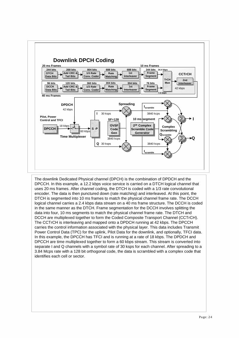
The downlink Dedicated Physical channel (DPCH) is the combination of DPDCH and the DPCCH. In this example, a 12.2 kbps voice service is carried on a DTCH logical channel that uses 20 ms frames. After channel coding, the DTCH is coded with a 1/3 rate convolutionalencoder. The data is then punctured down (rate matching) and interleaved. At this point, the DTCH is segmented into 10 ms frames to match the physical channel frame rate. The DCCH logical channel carries a 2.4 kbps data stream on a 40 ms frame structure. The DCCH is coded in the same manner as the DTCH. Frame segmentation for the DCCH involves splitting the data into four, 10 ms segments to match the physical channel frame rate. The DTCH and DCCH are multiplexed together to form the Coded Composite Transport Channel (CCTrCH). The CCTrCH is interleaving and mapped onto a DPDCH running at 42 kbps. The DPCCH carries the control information associated with the physical layer. This data includes Transmit Power Control Data (TPC) for the uplink, Pilot Data for the downlink, and optionally, TFCI data. In this example, the DPCCH has TFCI and is running at a rate of 18 kbps. The DPDCH and DPCCH are time multiplexed together to form a 60 kbps stream. This stream is converted into separate I and Q channels with a symbol rate of 30 ksps for each channel. After spreading to a 3.84 Mcps rate with a 128 bit orthogonal code, the data is scrambled with a complex code that identifies each cell or sector.
Page: 25
244 Data Bits
+
12.2 kbps Speech
16 Bits CRC
268 Bits/20 ms = 13,400 bps
8 Bits Tail=
20 ms/frame
+
268 Data Bits
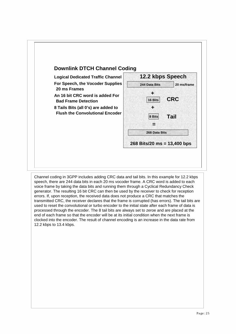
Downlink DTCH Channel CodingLogical Dedicated Traffic ChannelFor Speech, the Vocoder Supplies 20 ms Frames
An 16 bit CRC word is added For Bad Frame Detection
8 Tails Bits (all 0’s) are added to Flush the Convolutional Encoder
Channel coding in 3GPP includes adding CRC data and tail bits. In this example for 12.2 kbps speech, there are 244 data bits in each 20 ms vocoder frame. A CRC word is added to each voice frame by taking the data bits and running them through a Cyclical Redundancy Check generator. The resulting 16 bit CRC can then be used by the receiver to check for reception errors. If, upon reception, the received data does not produce a CRC that matches the transmitted CRC, the receiver declares that the frame is corrupted (has errors). The tail bits are used to reset the convolutional or turbo encoder to the initial state after each frame of data is processed through the encoder. The 8 tail bits are always set to zeroe and are placed at the end of each frame so that the encoder will be at its initial condition when the next frame is clocked into the encoder. The result of channel encoding is an increase in the data rate from 12.2 kbps to 13.4 kbps.

Page: 26
Data In13.4 kbps
Data Out13.4 kbps
Data Out13.4 kbps
+D D DD D DD D
++ Data Out
13.4 kbps
Downlink Convolutional EncoderUses either a 1/2 or 1/3 Rate CoderOptionally can use no Encoder
Convolutional encoding is used to provide increased error detection and correction capabilities for the receiver. The BCH, PCH, and FACH use a one half rate convolutional encoder that double the bit rate of the input data stream. The DPCH uses a one third rate or one half rateconvolutional encoder for lower rate services and a one third rate turbo encoder for higher data rate services. In this example, a one third rate convolutional encoder is used. The encoder generates three output streams at the same rate as the input data stream. These output streams are multiplexed together to produce a single stream three times as fast as the original data stream. The unique redundancy of the output stream allow efficient Viterbi decoding that can correct many reception errors. The error correction encoders are feed the input data on a per frame basis. The last eight bits of each frame are the 8 tail bits (all zeroes). Since these are the last bits clocked into the encoder, the state of the 8 “D” flip flops in the encoder are set to zero. Thus, when the next frame of data is clocked into the encoder, it starts out each new frame at the zeroed out condition.
Page: 27
Turbo Coding OptionNew Error Correction Codes Have Been Developed That Out Perform Convolutional Encoders for High Rate Data Transmissions: Turbo Codes
Unlike Convolutional Codes, Turbo Codes cannot be Described in Closed Mathematical Form:
• “Trial and Error” Development
Can Yield up to 0.5 dB Performance Improvement in Required S/N
To lower the transmit power required for data transmissions (and thus lower the interference and raise capacity), new error correction and detection encoding schemes have been developed. These encoders are designed to replace the convolutional encoders and have better correction performance while maintaining the same data rate. Turbo encoders are one class of these new encoders. Turbo encoders do not have a closed mathematically description. They must be developed on a trial and error basis. First claims of better performance for Turbo coders than convolutional encoders were met with widespread doubt as mathematicians believed such performance was impossible. Testing has shown that turbo coders do indeed improve the error rate performance of a transmission system. Turbo coders provide a reduction of transmit power up to 0.5 dB for the same error rate performance when compared againstconvolutional encoders.

Page: 28
Turbo Coder Example
Uses the Same Coder for Both Parity Generators
Second Parity Generator Input is Interleaved
Yields 0.5 dB Improvement Relative to Convolution Encoder for High Speed Data
Interleaver
+D D D
++
+
64 kbpsOutput
64 kbpsOutput64 kbps
Input
D D D
++
+ + 64 kbpsOutput
Systematic Path
Parity Path
Parity Path
This slide shows the general Turbo Coder specified by 3GPP for high speed data transmissions. Here in this example, data is input to the encoder at a rate of 64 kbps. One path in the Turbo Coder simply sends the original data through to the output without modification. This path is known as the Systematic Path. A second path adds redundancy by clocking the data through a feedback shift register system that modifies the data in a predictable manner. The output of this path is also at a rate 64 kbps. This coded path is called a Parity Path. The third path uses the same coder as the first Parity Path except that the input data is passed through an interleaver. The output of the interleaved Parity Path also runs at 64 kbps. The three resulting data streams are then multiplexed together to form a single stream that runs at three times the original rate. The net result is that the Turbo Coder has 0.5 dB better performance than the convolutional encoder.

Page: 29
DTCH at 40,200 bps804 Bits per 20 ms Frame
Data Punctured 15.4% = 34,400 bps688 Bits per 20 ms Frame
Rate MatchingUnequal Repeat or Puncture:
• Data is Punctured to a Lower Rate if: 0.8 < Ratio < 1• Otherwise the Data is Repeated up to the Next Rate
In this Example, the DTCH Data is Punctured from 804 bits/frame to 688 bits/frame (40,200 bps to 34,400 bps)
Rate matching in 3GPP is accomplished by unequal repeating of the bits to match the next higher system rate or by puncturing the bits down the next lower system rate. The rules for rate matching are: if the next lower system bit rate is greater than 80% of the input bit rate and less than 100% of the input bit rate, then the input data is punctured. Otherwise, the input data in unequally repeated up to match the nxt higher system rate. The goal is to have the CCTrCH(which may contain several transport channel) match one of the acceptable system symbols rates (after bit to I/Q symbol conversion): 7.5 ksps, 15 ksps, 30 ksps, 60 ksps, 120 ksps, 240 ksps, 480 ksps, and 960 ksps. All services must be rate matched to one of these system symbol rates. In this example, the logical DTCH has a bit rate of 40.2 kbps after convolutional encoding. The logical DCCH has a bit rate of 9 kbps after coding. The DTCH is punctured down to 34.4 kbps because it results in the next lower rate while preserving at least 80% of the original data. The DCCH is also punctured down from 9 kbps to 7.6 kbps in this case. After frame segmenting, the multiplexed DTCH and DCCH sum to form a CCTrCH of 42 kbps. After mapping onto a physical channel, the DPDCH is multiplexed with a DPCCH running at 18 kbps. The result is a 60 kbps stream, which after I/Q symbol mapping, exactly matches one of the available system symbols rates of 30 ksps.

Page: 30
Frame Segmentation & Interleaving
688 bits 344 bits688 bitsFrame
Segment
2ndInter-leaver
DTCH Logical Channel
42 kbps20 ms Frames10 ms Frames
34.4 kbps
7.6 kbps
RateMatching
1stInterleaver
304 bits 76 bits304 bitsFrame
Segment
DCCH Logical Channel
40 ms Frames
RateMatching
1stInterleaver
DCH Transport Channel
The Logical Channels are:• Individually Interleaved• Converted to 10 ms Frame Structures• Interleaved Together to Form a Dedicated Channel (Transport Channel)
After rate matching, the logical channels are independently interleaved. Once interleaved, each logical channel must be segmented to match the 10 ms frame structure used by the physical layer. In this example, the DTCH is a voice channel that operates with 20 ms frames. Frame segmentation for this logical channel splits each 20 ms frame of data into two 10 ms frames. The DCCH logical channel uses a 40 ms frame structure. Frame segmentation for the DCCH splits each 40 ms frame of data into four 10 ms frames of data. The frame segmentation process results in 10 ms frames for each channel. In this case, the DTCH has a data rate of 34.4 kbps and the DCCH has a data rate of 7.6 kbps. At this point the DTCH and DCCH are interleaved together to form the CCTrCH. The data rate of the CCTrCH is 42 kbps. Other combinations of logical services are possible. This example is just one possibility that illustrates the process.

Page: 31
DPCCH = DPDCH =
20 bits6
One Timeslot = 667 usec
4
Data 1
2
Data 2TPC
bits
Pilot
8 bits
Downlink DPDCH & DPCCH Time MultiplexingDPDCH and DPCCH are:
• Time Multiplexed Together each Timeslot• Power Control Bits are Repeated to Improve Reception• Power Control Update Rate is 1,500 bps • This Example is for a 60 kbps DPCH
TFCI
Once the CCTrCH transport channel is built, it must be mapped onto a physical channel. TheCCtrCH is mapped into the DPDCH. The physical channel is formed by time multiplexing the DPDCH and DPCCH together each timeslot. In this example, the DPDCH is running at a rate of 42 kbps and the DPCCH is running at a rate of 18 kbps. The two channels are multiplexed such that the TFCI data occupies the first two bits of the timeslot, followed by four DPDCH bits, then two bits of Transmit Power Control (TPC), 24 more bits of DPDCH data, and finally 8 bits of Pilot data. The TPC bits are repeated at least twice per timeslot to improve reception quality. Some timeslot formats transmit four or eight TPC bits. In any case, the update rate of the actual transmit power control commands is always 1500 bps:
2 TPC bits / timeslot = 1 Transmit Power Control Command / timeslot1 TPCC / timeslot * 15 timeslots / frame * 100 frames / second = 1500 commands per
second

Page: 32
Sample Downlink Configurations
SlotFormat
DPDCHBit Rate
DPCCHBit Rate
TFCII nfo ?
DPCHBit Rate
I /Q SymbolRate
OVSFLength
0 6 kbps 9 kbps No 15 kbps 7.5 ksps 512
2 24 kbps 6 kbps No 30 kbps 15 ksps 256
8 51 kbps 9 kbps No 60 kbps 30 ksps 128
11 42 kbps 18 kbps Yes 60 kbps 30 ksps 128
12 90 kbps 30 kbps Yes 120 kbps 60 ksps 64
13 210 kbps 30 kbps Yes 240 kbps 120 ksps 32
14 432 kbps 48 kbps Yes 480 kbps 240 ksps 16
15 912 kbps 48 kbps Yes 960 kbps 480 ksps 8
16 1872 kbps 48 kbps Yes 1920 kbps 960 ksps 4
A number of different configurations of the DPDCH and DPCCH are possible in the 3GPP system. The data rates for these combinations vary according to the input rate and the data that is carried on the DPCCH (such as optional TFCI data). This table shows some of the available combinations. The table show the slot format (denoted by a number), the data rate of the DPDCH after error coding and rate matching, the data rate of the DPCCH, TFCI information, the combined physical channel data rate, the symbol rate after I/Q conversion, and the spread factor (OVSF code length). To achieve higher throughput rates, multiple DPDCHsare used (remember, that the DPDCH rates shown are after error coding and rate matching).

Page: 33
DPCCH = DPDCH =
20 bits6
One Timeslot = 667 usec
4
Data 1
2
Data 2
TPC
bits
Pilot
8 bits
DPDCH & DPCCH GainDPDCH and DPCCH can Have Independent Gain Settings
TFCI
To increase the reliability of the control information, the power of the DPCCH can be adjusted relative to the power of the DPDCH. Reception errors in the TFCI, TPC or Pilot data can have large negative effects on system performance. By raising the power in these symbols, the error rate can be keep to acceptable levels. It is important to remember that the TPC and Pilot data are not convolutionally encoded and so do not have the same robustness as the DPDCH symbols or the TFCI symbols.

Page: 34
Q
ISerial toParallel
Converter
S -P
Time MultiplexedDPDCH and DPCCH
Data Stream
101101001000110
Downlink Serial to Parallel ConversionTime Multiplexed DPDCH/DPCCH Data Stream is Converted into 2 bit Wide Parallel Data (Symbols)
Provides True QPSK Modulation format
Since the 3GPP system uses true QPSK modulation in the downlink, the data stream is serial to parallel converted after the DPDCH and DPCCH are multiplexed together. The result is two data streams that run at half of the original input data rate. One branch is designated as the I (in phase) channel data stream while the other is designated as the Q (quadrature) channel data stream.
Page: 35
1 1 1 1 1 1 1 1
1 1 1 1 -1 -1 -1 -1
1 1 -1 -1
1 1 1 1
1 1
1 -1
1 -1 1 -1
1 -1 -1 1
1 1 -1 1 -1 1 -1 1 -1
1 -1 1 -1 -1 1 -1 11 -1 -1 1 1 -1 -1 1
1 -1 -1 1 -1 1 1 -1
1 1 -1 -1 -1 -1 1 1
1 1 -1 -1 1 1 -1 -1
SF=1 SF=2 SF=4 SF=8
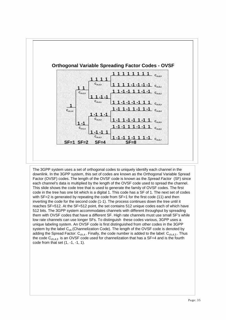
Orthogonal Variable Spreading Factor Codes - OVSF
Cch,1,0
Cch,2,0
Cch,2,1
Cch,4,0
Cch,4,1
Cch,4,2
Cch,4,3
Cch,8,0
Cch,8,1
Cch,8,2
Cch,8,3
Cch,8,4
Cch,8,5
Cch,8,6
Cch,8,7
The 3GPP system uses a set of orthogonal codes to uniquely identify each channel in the downlink. In the 3GPP system, this set of codes are known as the Orthogonal Variable Spread Factor (OVSF) codes. The length of the OVSF code is known as the Spread Factor (SF) since each channel’s data is multiplied by the length of the OVSF code used to spread the channel. This slide shows the code tree that is used to generate the family of OVSF codes. The first code in the tree has one bit which is a digital 1. This code has a SF of 1. The next set of codes with SF=2 is generated by repeating the code from SF=1 for the first code (11) and then inverting the code for the second code (1-1). The process continues down the tree until it reaches SF=512. At the SF=512 point, the set contains 512 unique codes each of which have 512 bits. The 3GPP system accommodates channels with different throughput by spreading them with OVSF codes that have a different SF. High rate channels must use small SF’s while low rate channels can use longer SFs. To distinguish these codes various, 3GPP uses a unique labeling system. An OVSF code is first distinguished from other codes in the 3GPP system by the label Cch (Channelization Code). The length of the OVSF code is denoted by adding the Spread Factor: Cch,4 . Finally, the code number is added to the label: Cch,4,3 . Thus the code Cch,4,3 is an OVSF code used for channelization that has a SF=4 and is the fourth code from that set (1, -1, -1, 1).

Page: 36
SF=16SF=2 SF=4 SF=81 1 1 1 1 1 1 1
1 1 1 1 -1 -1 -1 -1
1 1 -1 -1
1 1 1 1
1 1
1 -1
1 -1 1 -1
1 -1 -1 1
1
1 -1 1 -1 1 -1 1 -1
1 -1 1 -1 -1 1 -1 1
1 -1 -1 1 1 -1 -1 1
1 -1 -1 1 -1 1 1 -1
1 1 -1 -1 -1 -1 1 1
1 1 -1 -1 1 1 -1 -1
1 1 1 1 1 1 1 1 1 1 1 1 1 1 1 11 1 1 1 1 1 1 1 -1 -1 -1 -1 -1 -1 -1 -1
1 1 1 1 -1 -1 -1 -1 1 1 1 1 -1 -1 -1 -11 1 1 1 -1 -1 -1 -1 -1 -1 -1 -1 1 1 1 1
1 1 -1 -1 1 1 -1 -1 1 1 -1 -1 1 1 -1 -11 1 -1 -1 1 1 -1 -1 -1 -1 1 1 -1 -1 1 1
1 1 -1 -1 -1 -1 1 1 1 1 -1 -1 -1 -1 1 11 1 -1 -1 -1 -1 1 1 -1 -1 1 1 1 1 -1 -1
1 -1 1 -1 1 -1 1 -1 1 -1 1 -1 1 -1 1 -11 -1 1 -1 1 -1 1 -1 -1 1 -1 1 -1 1 -1 1
1 -1 1 -1 -1 1 -1 1 1 -1 1 -1 -1 1 -1 11 -1 1 -1 -1 1 -1 1 -1 1 -1 1 1 -1 1 -1
1 -1 -1 1 1 -1 -1 1 1 -1 -1 1 1 -1 -1 11 -1 -1 1 1 -1 -1 1 -1 1 1 -1 -1 1 1 -1
1 -1 -1 1 -1 1 1 -1 1 -1 -1 1 -1 1 1 -11 -1 -1 1 -1 1 1 -1 -1 1 1 -1 1 -1 -1 1
Using Shorter OVSF Codes Precludes Using all Longer Codes Derived from the Original
Shorter Codes on a Branch map into Longer Codes
Effects of Variable OVSF Codes
A key point is that every code at a given SF is orthogonal to any other code at the same SF. In addition, codes with a different SF that are not on the same branch are also orthogonal. However, codes that are on the same branch with different SF are NOT orthogonal. The effects of this becomes clear when using high data rate channels (short OVSF codes). If, for example, a channel uses an OVSF with spread factor equal to four, then all OVSF codes derived from that code ( on the same branch) cannot be used by the base station. This is because all of the longer OVSF codes on that branch are derived from the parent code (they are NOT orthogonal). In this example, the SF=4 OVSF code is: 1 1 -1 -1. If we compare this code to the first code at the SF=8 level, we find that this code is: 1 1 -1 -1 1 1 -1 -1 ( it is simply the SF=4 code repeated twice). If a receiver decodes a channel and receives the 1 1 -1 -1 1 1 -1 -1 bit pattern, there is no way to tell if the modulating data was -1 (SF=8) or -1 -1 (SF=4). This means that a base station must carefully allocate OVSFD codes to assure that all channels remain orthogonal. It also means that as more high rate channels are allocated, the number of available OVSF codes for the system to use is greatly reduced.

Page: 37
1 1 1 1 1 1 1 1
1 -1 -1 1 1 -1 -1 1
OVSF Codes with SF=8
Matches = 4
Mismatches = 4
Net Correlation = 0
Match? Y N N Y Y N N Y
Code
Code
Orthogonality of OVSF Codes
Like Walsh Codes Used in IS-95 CDMA, OVSF codes are :
• Orthogonal with each Other and Their Inverses:• Orthogonality = Equal Number of Matches and
Mismatches
Voice Channels Uses the OVSF Code with a SF (spread factor) of 128
These are essentially the same codes as the Walsh codes used by the IS-95 CDMA system. OVSF codes are orthogonal to each other because they always have a net correlation of zero. For a digital sequence, such as the OVSF codes, a simple test for orthogonality is to compare the number of matches and mismatches (read by columns). Orthogonal codes will have have equal number of matches and mismatches for a net correlation of 0. Orthogonal code sets are always orthogonal to all other codes in the set of the same spread factor and their inverses (1 changed to -1 and -1 to 1). However, as was discussed in the previous slide, orthogonality is not guaranteed for codes of different spread factor.
Page: 38
Q
ISerial toParallel
Converter
S -P 128 bit OVSFGenerator
3840 kcps
3840 kcps
3840 kcps
3840 kcps
30 ksps
30 ksps
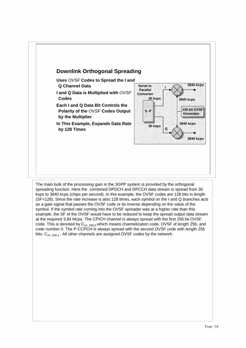
Downlink Orthogonal SpreadingUses OVSF Codes to Spread the I and Q Channel Data
I and Q Data is Multiplied with OVSFCodes
Each I and Q Data Bit Controls the Polarity of the OVSF Codes Output by the Multiplier
In This Example, Expands Data Rate by 128 Times
The main bulk of the processing gain in the 3GPP system is provided by the orthogonal spreading function. Here the combined DPDCH and DPCCH data stream is spread from 30ksps to 3840 kcps (chips per second). In this example, the OVSF codes are 128 bits in length (SF=128). Since the rate increase is also 128 times, each symbol on the I and Q branches acts as a gate signal that passes the OVSF code or its inverse depending on the value of the symbol. If the symbol rate coming into the OVSF spreader was at a higher rate than this example, the SF of the OVSF would have to be reduced to keep the spread output data stream at the required 3.84 Mcps. The CPICH channel is always spread with the first 256 bit OVSFcode. This is denoted by Cch, 256,0 which means channelization code, OVSF of length 256, and code number 0. The P-CCPCH is always spread with the second OVSF code with length 256bits: Cch, 256,1 . All other channels are assigned OVSF codes by the network. .

Page: 39
Downlink Scrambling
Each Cell Uses a Different CodeUse a 10 ms segment of a 218-1 Gold Code (38400 Chips)
Q Code is Offset 131,072 chipsTotal Number of Codes =262,143Use only 8,192 Codes
• Broken into 512 Sets of Codes• Each Set has 1 Primary Code with 15
Secondary Codes• Primary Codes are Further Broken into 64
Code Groups, Each with 8 Primary Codes
3840 kcps
3840 kcps
ComplexScrambling
131,072Chip Offset Q
I+
+
+
-
10 ms segment
218-1I Channel
Scramble CodeGenerator
A complex scrambling code is used to “cover” the channels that use the OVSF codes forchannelization. Without the scrambling, each adjacent cell would be using the same OVSF codes, which would result in high interference. The complex scrambling code also provides a method to distinguish one base station or sector from another. These complex scrambling codes are 10 ms segments of 218-1 Gold Codes (38400 chips). The I and Q codes use the same generator but are separated in time by 131,072 chips. This offset produces I and Q sequences that are sufficiently independent to be uncorrelated. There are 262,143 possible scramble codes in the 3GPP WCDMA system. The 262,143 codes are broken into 512 groups. Each group is identified by a Primary code and includes 15 Secondary codes that are associated with that groups’ Primary code. Every base station or sector of a base station isassigned one of the Primary scramble codes. The P-CCPCH always uses the Primary scramble code. Optionally, other channels may be scrambled using the Secondary codes associated with the Primary code. The 512 Primary codes are further divided into 64 groups with each group containing having 8 scramble codes. These groups directly correspond to the 64 possible Secondary Sync Channel code patterns. When the mobile determines the Secondary Sync Channel code pattern, the mobile then knows which of the 64 Primary scramble codes groups to search to find the exact Primary scramble code of the base station (8 possible codes).

Page: 40
Shift Register 1
Shift Register 217 16 15 14 13 12 11 10 9 8 7 6 5 4 3 2 1 0
17 16 15 14 13 12 11 10 9 8 7 6 5 4 3 2 1 0
I
Q
DL Scramble Code Generator218 Gold Code Generator Clocked at 3.84 Mcps
• Initial State: Desired Code in Reg. 1 & all 1’s into Reg. 2• Pattern resets after 10 ms (38400 chips)
The downlink complex scramble code generator is a 218-1 Gold Code generator. The complex scramble code generator is clocked at the chip rate of 3.84 Mcps. Gold Code generators have two pseudo random, feedback shift register based on different polynomials. Each feedback shift register has feedback taps at different points. The feedback location indicates a factor in the polynomial: x18 + x7 + 1 for the top generator and x18 + x10 + x7 + x5 + 1 for the lower generator. The final I channel code is the XOR of the two feedback shift register’s outputs. The final Q code is generated by tapping the generators at different locations and then doing a XOR on the two outputs. To start the gold code sequence, the upper generator is loaded with the desired code and the lower generator is loaded with all 1’s. After running for 10 ms, the two generators are reset to the initial conditions and restarted. Thus the complex scramble pattern for a given code repeats every 10 ms. The complex scramble code (either the primary or one of the associated secondary codes) is applied to all down link channels except for the Sync channel. Of course, the 512 possible codes must be used in cells spaced far enough apart to preclude interference. This requires some code planning, but present no major obstacle.
Page: 41
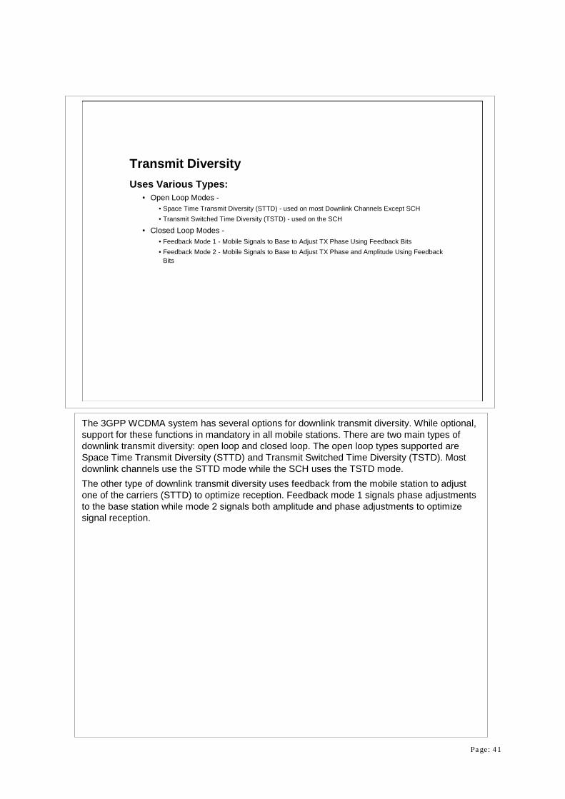
Transmit DiversityUses Various Types:
• Open Loop Modes -• Space Time Transmit Diversity (STTD) - used on most Downlink Channels Except SCH• Transmit Switched Time Diversity (TSTD) - used on the SCH
• Closed Loop Modes -• Feedback Mode 1 - Mobile Signals to Base to Adjust TX Phase Using Feedback Bits• Feedback Mode 2 - Mobile Signals to Base to Adjust TX Phase and Amplitude Using Feedback
Bits
The 3GPP WCDMA system has several options for downlink transmit diversity. While optional, support for these functions in mandatory in all mobile stations. There are two main types of downlink transmit diversity: open loop and closed loop. The open loop types supported are Space Time Transmit Diversity (STTD) and Transmit Switched Time Diversity (TSTD). Most downlink channels use the STTD mode while the SCH uses the TSTD mode.The other type of downlink transmit diversity uses feedback from the mobile station to adjust one of the carriers (STTD) to optimize reception. Feedback mode 1 signals phase adjustments to the base station while mode 2 signals both amplitude and phase adjustments to optimize signal reception.
Page: 42
Antenna1
Antenna2TSTD Switch
256 chips per Timeslot
Primary GoldCode
PrimarySCH
SecondarySCH
Secondary GoldCode Pattern
Each 256 chip Burstis Alternated BetweenAntenna A and Antenna B
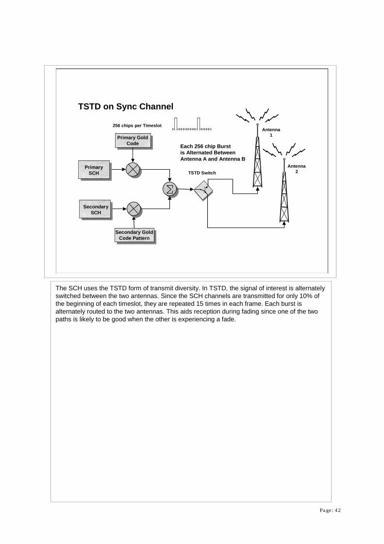
TSTD on Sync Channel
The SCH uses the TSTD form of transmit diversity. In TSTD, the signal of interest is alternately switched between the two antennas. Since the SCH channels are transmitted for only 10% of the beginning of each timeslot, they are repeated 15 times in each frame. Each burst is alternately routed to the two antennas. This aids reception during fading since one of the two paths is likely to be good when the other is experiencing a fade.
Page: 43
Antenna1
Primary Pilot OVSF Code
PrimaryCPICH
DPDCHData
Diversity Pilot OVSF Code
Antenna2DPCCH
Data
Multiplexer
DiversityCPICH
STTD Encoder
S1, S2
S1, S2
-S2, S1
Scramble Code
DPCH OVSF Code
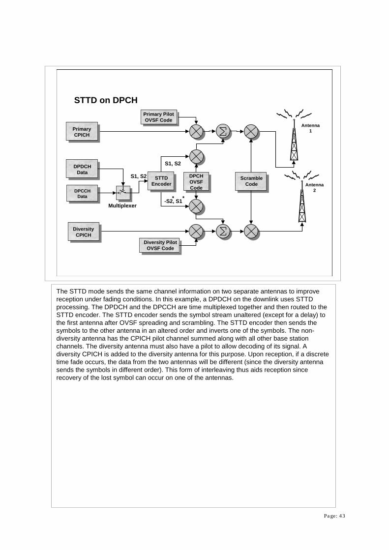
STTD on DPCH
**
The STTD mode sends the same channel information on two separate antennas to improve reception under fading conditions. In this example, a DPDCH on the downlink uses STTD processing. The DPDCH and the DPCCH are time multiplexed together and then routed to the STTD encoder. The STTD encoder sends the symbol stream unaltered (except for a delay) to the first antenna after OVSF spreading and scrambling. The STTD encoder then sends the symbols to the other antenna in an altered order and inverts one of the symbols. The non-diversity antenna has the CPICH pilot channel summed along with all other base station channels. The diversity antenna must also have a pilot to allow decoding of its signal. A diversity CPICH is added to the diversity antenna for this purpose. Upon reception, if a discrete time fade occurs, the data from the two antennas will be different (since the diversity antenna sends the symbols in different order). This form of interleaving thus aids reception since recovery of the lost symbol can occur on one of the antennas.

Page: 44
SSDT During Soft HandoffSite Selection Diversity Transmit Power Control (SSDT) is:
• An Optional Method to Improve Capacity During Soft Handoff• Each Base Station is Given a Temporary ID• Uses Mobile’s FBI (Feedback) Bits to Select the Best Base Station to Transmit (Sends
Temp ID)• Mobile Monitors CPICH Strength of all Cells and Sends new ID when Another Base
Station Becomes Stronger
Another form of transmit diversity used in the 3GPP WCDMA system during soft handoff conditions is called Site Selection Diversity Transmit Power Control (SSDT). In this case, each base station is assigned a temporary ID. The mobile then measures all nearby base stations and determines which has the best signal. The mobile then selects this base station as the primary transmitter. This information is quickly carried back to the base station using the feedback bits in each timeslot. The primary cell then transmits to the mobile while all other cells turn off their channel directed to that particular mobile station. If the mobile detects that one of the other cells has a better signal, it sends the feedback bits back to select this cell as the new primary transmitter. This is accomplished without higher layers of protocol and so provides an efficient method of reducing interference while preserving the benefits of soft handoff.

Page: 45
Acquisition Indication ChannelAICH Provides an Indicator to the Mobile that a PRACH or PCPCH from the Mobile has been Detected
Uses 1.33 ms Access Slots (15 slots per 20ms)Each Access Slot Provides 16 Access Indicators for 16 Mobiles inthe 1.067 ms Transmission Period
No Data is Sent Last 4 Symbols of Each SlotUses the Same Physical Channel Structure as DPDCH/DPCCH
The Acquisition Indication Channel (AICH) is used by the base station to signal a mobile that it has received a valid Physical Random Access Channel or a Physical Common Packet Channel transmission from a mobile. When the mobile receives an indication on the AICH in response to a PRACH, it then reads the BCH to determine system properties. The AICH is transmitted in 1.33 msec access slots (5120 chips). Each access slot can carry up to 16 access indicators (AI) allowing the base station to indicate reception of access attempts from 16 different mobile stations. Each of the 16 AI’s directly corresponds to one of the 16 signature codes sent by a mobile PRACH or PCPCH .The access indicators are transmitted in the first 1.067 ms of each slot. No data is sent during the last four symbols of each slot. The spreading and modulation of the AICH is very similar to that of the DPDCH/DPCCH .

Page: 46
AICH Timing10 ms
7680 Chips
Common Pilot ChannelCPICH
S-CCPCH S-CCPCH
Primary SCH
Secondary SCH
PICH PICH
Primary Common Control Physical Channel
10 ms
AICHSlot#0
Slot#1
Slot#2
Slot#3
Slot#4
Slot#5
Slot#6
Slot#7
Slot#8
Slot#9
Slot#10
Slot#11
Slot#12
Slot#13
Slot#14
The AICH is time aligned to the frame timing of the P-CCPCH.

Page: 47
Frame 1 Frame 2
15 timeslots active 10 timeslots active15 timeslots active 15 timeslots active 15 timeslots active
Frame 4 Frame 5
Frame 3 CompressedTransmitted Power
Compressed Mode OperationDownlink Compresses and Bursts the DPDCH/DPCCHAllows “Off” Reception Times for Mobile to Make Measurements on Other Frequencies
Two Methods:• Reduce Spread Factor by 2 (Shorter OVSF)• Puncture Coder (1/3 rate to 1/2 rate)
To allow mobiles to have time to measure the signal strength of other frequencies in use in a 3GPP system, a compressed mode of operation is defined. This compressed mode transmits the data in a frame at a faster rate to allow the downlink to temporarily turn off. There are two defined methods for achieving faster transmission: first by reducing the spread factor by 2, and secondly by puncturing the convolutional encoder to a lower rate. In both cases, the data is transmitted in fewer timeslots in a frame. In the first method, the data is spread with a shorter OVSF that reduces the processing gain but increases the channel data rate. In the second technique, the coder is punctured to a lower rate which reduces the number of symbols to be transmitted. In either case, the downlink then transmits the data without using all of the available timeslots. Either method reduces the processing gain applied to the channel. To compensate for the reduced processing gain, the downlink transmits the compressed timeslots with a higher power. During the unused timeslots, the mobile can tune its receiver to another frequency and measure its signal quality.

Page: 48
Physical Uplink Channels
PRACH (Physical Random Access Channel).• Carries the RACH (Random Access Channel)• Used for System Access
PCPCH (Physical Common Packet Channel)• Carries the CPCH (Common Packet Channel)• Used to Carry Small to Medium Packets and Support Contention Resolution
DPCH (Dedicated Physical Channel) Composed of:• DPDCH (Dedicated Physical Data Channel).• DPCCH (Dedicated Physical Control Channel).
The Uplink (transmissions from mobile to base) in the 3GPP system is quite different from the Downlink. There are just three types of physical channels that can be transmitted by mobile station: the Physical Random Access Channel (PRACH), the Physical Common Packet Channel (PCPCH), and the combination of the Dedicated Physical Data Channel (DPDCH) and the Dedicated Physical Control Channel (DPCCH). The PRACH carries the Random Access Channel (RACH), which is a transport channel. The PCPCH carries the Common Packet Channel (CPCH), which is a transport channel. The DCH transport channel is carried by the DPDCH/DPCCH combination.

Page: 49
Message Burst10 ms
1.33 ms Access Slots
1.067 msPreamble
1.067 msPreamble
1.067 msPreamble
Uplink PRACHSends Signaling Information to the Base StationIs Composed of Two Parts:
• One or More 1.067 ms Duration Preambles which the Base Station Searches for to Acquire PRACH channels
• A 10 ms Message Section
PRACH uses a Slotted-Aloha Approach:• Mobile Is Allowed to Transmit in 1.33 ms Access Slots
The Uplink PRACH is used to make initial contact with a base station and then to convey signaling messages to the network when the mobile is not on a DPDCH/DPCCH. A PRACH is composed of two distinct parts: a number of preambles and a message portion. The PRACH preambles are 1.067 ms bursts (4096 chips) of a complex signature consisting of 16 symbols that are scrambled with a cell specific, 4096 chip long segment of a 225 Complex Gold Code generator. There are 16 available complex signatures. Adjacent cells must use different scrambling codes to eliminate confusion as to which cell the mobile station is trying to contact. More than one scrambling code may be used by a cell if loading demands it. The preambles are transmitted in predefined access slot of 1.333 ms duration. This means that there are 15 access slots every two frames (15 * 1.33 = 20 ms). The preambles are repeated until the base station acknowledges receiving the preamble on the AICH. Once the mobile receives a reception indication on the AICH, it transmits the message portion of the PRACH. The message portion is 10 ms in length and uses a modulation scheme that is very similar to that of the combined DPDCH/DPCCH. The Physical Common Packet Channel (PCPCH) used a very similar scheme with the exception that a collision resolution preamble is sent once the base station responds on the AICH. A 10 ms power control preamble is then sent followed by the message packet.

Page: 50
15 014 13 12 11 10 9 8 7 6 5 4 3 2 1
16 Bit Signature Sequence
PRACH Preamble (1.067 ms)
Plays the sequence 256 times
4096 Bit Segmentof a 225 Gold Code
3.84 Mcps
PRACH PreamblePreamble data is 1 of 16 Hadamard Sequences Repeated 256 Times (called a Signature)
Each Signature has a Length of 16 bitsPreamble is Scrambled with a 4096 chip Segment of a 3.84 McpsComplex Long Code
The PRACH signature (modulating data) is a Hadamard sequence with 16 symbols of data. There are 16 possible signature patterns. These patterns are repeated 256 times in every 1.067 ms preamble. All signature codes are orthogonal to each other. The signature data is then scrambled against a 4096 chip long segment of a 225 Complex Gold Code generator. Only the first 4,096 of the possible 16,777,216 possible codes are used (only 224 codes are used). The scrambling code and preamble signature codes run at the 3.84 Mcps rate which means that the signature code is repeated 256 times during the preamble (256 codes * 16 chips/code *0.2604 usec/chip = 1.067 msec) . After scrambling, the data is transmitted using QPSK modulation. The base station transmits which of the 256 scrambling codes should be used for the preambles on the Broadcast Channel.

Page: 51
PRACH MessagePreamble Signature Points to a Node on the OVSF Code Tree at Spread Factor 16
Data Brach is Spread with Upper Branch OVSF:• Spread Factor is Variable from SF 32 to SF 256)
Control Branch is Spread with Lowest OVSF:• Always Spread with a 256 Bit OVSF
Scramble Code is a 10 ms Segment of a Complex Gold Code Sequence of Length 25
Uses Scramble Codes 4,096 to 42,495 for PRACH Messages:• Codes Correspond to the Preamble Spreading Code
The significance of the of the preamble signature is that it provides an aid to the base station in determining what OVSF codes will be used to spread the message portion of the PRACH. Since there are 16 possible signatures, the preamble signature points to a node on the OVSF code tree at SF=16. The message portion of the PRACH is transmitted using the I branch of the modulator for the message data and the Q branch for the control data (pilot bits and TFCI). The I branch (message data) is spread with an OVSF code that is on the upper branch of the OVSF tree at SF=16 that is derived from the node indicated by the preamble signature. The exact spread factor used on the I branch will vary with the data rate transmitted on the message portion of the PRACH. The Q branch is always spread with the SF=256 code that lies at the bottom of the branch of the OVSF tree at SF=16 indicated by the preamble signature. The following slide graphically illustrates this concept. Following OVSF spreading, the message portion of the PRACH is scrambled with a 10 ms segment of a complex gold code sequence of length 25. Scramble codes 4,096 to 42,495 are used for the message portion of the PRACH and they directly correspond to the scramble codes that spread the preamble portion of the PRACH. These codes are cell specific to prevent interference from adjacent cells.
Page: 52
Signature Sequence 1.........
Signature Sequence 16
SF = 16SF = 32
SF = 64 SF = 128 SF = 256
SF = 16SF = 32
SF = 64 SF = 128 SF = 256
Control OVSF
Control OVSF
Data OVSF
Data OVSF
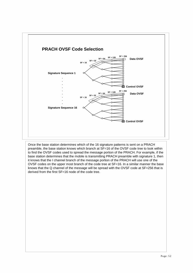
PRACH OVSF Code Selection
Once the base station determines which of the 16 signature patterns is sent on a PRACH preamble, the base station knows which branch at SF=16 of the OVSF code tree to look within to find the OVSF codes used to spread the message portion of the PRACH. For example, if the base station determines that the mobile is transmitting PRACH preamble with signature 1, then it knows that the I channel branch of the message portion of the PRACH will use one of the OVSF codes on the upper most branch of the code tree at SF=16. In a similar manner the base knows that the Q channel of the message will be spread with the OVSF code at SF=256 that is derived from the first SF=16 node of the code tree.

Page: 53
3840 kcps
Control OVSFGenerator
SF=256
Data OVSFGenerator
3840 kcps
SF=32 to 256
Message DataI
QPilot, & TFCI
ComplexScrambling
I+
+
+
-OVSF 2Generator
1,-1
Deciby 2
3840 kcps
225 ComplexScramble Code
Generator
3840 kcpsQ
PRACH Message Coding
The spreading of the PRACH channel uses the appropriate OVSF for the message portion and spreads the data to the final 3.84 Mcps. This spread data is applied to the I channel path. The control information associated with the physical channel is spread with a 256 bit OVSF to bring the data rate up to the final 3.84 Mcps. The spread control information is applied to the Q channel path. The spread I and Q paths are then scrambled by a mobile station specific long code. This scramble code is based on a 225 length gold code generator with a complex output. The gold code generator is capable of generating 224 unique codes since the MSB of the 225
generator is always set to 1. The scramble code generator is reset every frame to its initial condition to create a unique pattern that lasts one frame. HPSK scrambling is used to lower the peak to average ratio of the modulation. HPSK is explained further in this paper. Scramble codes 4,096 to 42,495 are reserved for the message portion of the PRACH and they have a one to one correspondence with the scrambling code used on the preamble portion of the PRACH. The exact codes are specified by the serving base station. The other available scramble codes are used to uniquely identify DPDCH/DPCCH uplink channels.

Page: 54
Add CRC & Tail Bits
268 bits
Pilot, Power Control, &TFCI
DPCCHData Bits
15 kbps3840 kcps SF=256
Data OVSFGenerator
3840 kcpsSF=64
244 bits1/3 Rate
Conv. Coder
804 bits1st
Interleaver
804 bitsRate
Matching
490 bits
Gain = - 6 dB
Gain
ComplexScrambling
I+
+
+
-OVSF 2Generator
1,-1
Deciby 2
I 3840 kcps
225
Scramble CodeGenerator
Q 3840 kcpsQ
402 bitsFrame
Segment
60 kbps
Control OVSFGeneratorCch,256,0
Cch,64,16
I Scramble Code
I Scramble Code
Q
Q
DTCHData Bits
60 kbps120 bits96 bits 360 bits 360 bits 110 bits90 bits
DPDCHData Bits
20 ms Frames
40 ms Frames
10 ms Frames49 kbps
Add CRC & Tail Bits
1/3 RateConv. Coder
1stInterleaver
RateMatching
11 kbps
Segment& Match
DCCHData Bits
Uplink Data Channel Air Interface
TrCHMux
60 kbps
CCTrCH2nd
Interleaver
The spreading and scrambling used on the uplink DPDCH/DPCCH differs from the downlink in two key areas: I/Q multiplexing of the DPDCH and the DPCCH, and the use of the scrambling codes as the channelization. In this example, the logical DTCH carries a 12.2 kbps voice channel and the logical DCCH carries a 2.4 kbps signaling channel. Each of these logical channels are channel coded, convolutionaly (or turbo) coded, and interleaved. The DTCH uses 20 msec frames. At the frame segmentation point, the DTCH is split into two parts to conform with the physical layer’s 10 ms frame structure. The DCCH, which operates with 40 ms frames, is split into 4 parts so that each signaling frame is spread over four 10 ms radio frames. These channels are then rate matched and multiplexed together prior to spreading. The multiplexed data at this point is called the Coded Composite Transport Channel (CCtrCH). After a second interleaving, the CCTrCH is mapped onto a DPDCH running at 60 kbps. The DPDCH is spread with an OVSF code with spread factor equal to 64 to reach the desired 3.84 Mcps. After gain scaling (to adjust the transmission power for the varying spread factor), the spread DPDCH is applied to the I channel. The DPCCH data is spread with an OVSF code with SF=256 to reach the 3.84 Mcps rate and is gain scaled in this example to be -6 dB relative to the DPDCH. The DPCCH is then applied to the Q channel. The scramble code generator is used to provide the unique channelization required for each mobile station.

Page: 55
Uplink Logical & Transport Channel Processing
Channel Coding:• Adds 16 bit CRC, 8 Tail Bits
Uses the 1/2 or 1/3 Rate Convolutional or Turbo Encoder1st Interleave on Individual Logical ChannelsFrame Segmentation (Order is Different than Downlink)
Rate Matching (Order is Different than Downlink)
Transport Channel Multiplexing to form CCTrCHSecond Interleave of CCTrCHMapping of CCTrCH onto a Physical Channel
The processing of logical and transport channels in the uplink is very similar to that of the downlink. The channel coding, convolutional or turbo coding, and interleaving processes for the uplink are the same as those in the downlink. The order of the next operations is slightly modified in the uplink. Each transport channel stream is segmented into 10 ms frames and then rate matched. Transport channel streams are them multiplexed to form a Coded Composite Transport Channel (CCTrCH). The CCTrCH is then interleaved and then mapped onto one or more physical channels.

Page: 56
Uplink DPDCH & DPCCHDPDCH carries the DataDPCCH carrier the Layer 1 Control InformationUnlike the Downlink, These Channels are I/Q Multiplexed (BPSK Modulation)
For Higher Data Rate Services, Additional DPDCHs are Added to Both the I and Q Branches
Link the downlink, the DPDCH and its associated DPCCH are the primary carriers of data in the uplink. The DPDCH carries the data while the DPCCH carries the layer 1 control information (pilot data, TPC, feedback, and optionally TFCI). Although similar in function to the DPDCH and DPCCH on the downlink, the uplink versions of these channels are coded in a different manner. The DPDCH and DPCCH on the uplink are not time multiplexed together but are code multiplexed onto the I and Q channels. Thus the DPDCH and the DPCCH use BPSK modulation. The resulting complex constellation looks like QPSK since each channel BPSK modulates the I and Q channels respectively. If a service requires data throughput that cannot be handled by a single DPDCH, then additional DPDCHs are code multiplexed onto the I and Q channels.

Page: 57
DPCCH at 15 ksps
DPDCH at 60 ksps
40 bits
2 bits5 bits
One Timeslot = 667 usec
1 bit
Data
Pilot FBI
2 bits
TFCI
I
Q
DPDCH & DPCCH Framing
TPC
The uplink channels use the same 10ms frame structure with 15 timeslots as found in the downlink. A typical DPDCH running at 60 ksps has 40 data bits in each 667 usec timeslot. A typical configuration for the associated DPCCH runs at 15 ksps with 10 bits in each timeslot. In this example, 5 bits are allocated for the embedded pilot channel, two bits for transmit power control, one for feedback information, and two for the optional TFCI. The feedback bit is used for closed loop transmit diversity or to select the downlink base station when in soft handoff conditions (SSDT - Site Selection Diversity transmission). For closed loop transmit diversity, the feedback bit is used to tell the base station to adjust the phase and/or amplitude of the of two carriers to optimize performance.
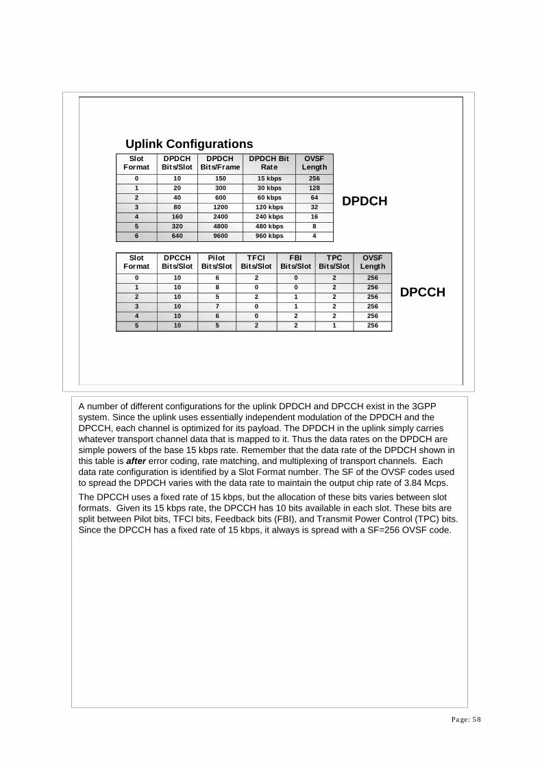
Page: 58
Uplink ConfigurationsSlot
FormatDPDCHBits/Slot
DPDCHBits/Frame
DPDCH BitRate
OVSFLength
0 10 150 15 kbps 2561 20 300 30 kbps 1282 40 600 60 kbps 643 80 1200 120 kbps 324 160 2400 240 kbps 165 320 4800 480 kbps 86 640 9600 960 kbps 4
DPDCH
SlotFormat
DPCCHBits/Slot
PilotBits/Slot
TFCIBits/Slot
FBIBits/Slot
TPCBits/Slot
OVSFLength
0 10 6 2 0 2 2561 10 8 0 0 2 2562 10 5 2 1 2 2563 10 7 0 1 2 2564 10 6 0 2 2 2565 10 5 2 2 1 256
DPCCH
A number of different configurations for the uplink DPDCH and DPCCH exist in the 3GPP system. Since the uplink uses essentially independent modulation of the DPDCH and the DPCCH, each channel is optimized for its payload. The DPDCH in the uplink simply carries whatever transport channel data that is mapped to it. Thus the data rates on the DPDCH are simple powers of the base 15 kbps rate. Remember that the data rate of the DPDCH shown in this table is after error coding, rate matching, and multiplexing of transport channels. Each data rate configuration is identified by a Slot Format number. The SF of the OVSF codes used to spread the DPDCH varies with the data rate to maintain the output chip rate of 3.84 Mcps. The DPCCH uses a fixed rate of 15 kbps, but the allocation of these bits varies between slot formats. Given its 15 kbps rate, the DPCCH has 10 bits available in each slot. These bits are split between Pilot bits, TFCI bits, Feedback bits (FBI), and Transmit Power Control (TPC) bits. Since the DPCCH has a fixed rate of 15 kbps, it always is spread with a SF=256 OVSF code.

Page: 59
Uplink Gain ValuesEach Uplink Channel is Scaled by the factor βThe Maximum Value of β is 1The Channel with the Highest Power has by Definition β=1.β is Quantized into four bits (16 levels):
• 1.0, 0.9333, 0.666, 0.8• 0.7333, 0.6667, 0.6, 0.5333• 0.4667, 0.4, 0.3333, 0.2667• 0.2, 0.1333, 0.0667, 0ff
Each uplink channel is scaled by a Gain Factor (β) depending on its processing gain. If the channel is running with a long OVSF (high processing gain), then it can be scaled lower in level. Channels that are sending high speed data (short OVSF spreading code) must be scaled higher to compensate for their reduced processing gain. A channel can be shut off by selecting the lowest β value. The channel with the highest power is always defined to have β =1. All other channels must be scaled with values of β≤1. The gain steps are quantized into four bits of data which yield sixteen discrete gain settings.

Page: 60
DPCCHData Bits
Pilot, Power Control,& Rate Info
3840 kcps
Control OVSFGenerator
I Branch
Data OVSFGenerator
3840 kcps
Channel CodedDPDCH Data Bits
Q Branch
Traffic Data
SF=256
SF=64
15 ksps
60 ksps
Cch,256,0
Cch,64,16
Uplink Orthogonal SpreadingThe DPDCH & DPCCH are Spread with Different OVSF Codes (independent Channels)
Produces BPSK Spreading on I and Q channels
For Higher Rate Transmissions, Additional DPDCH’s can be Modulated on I or Q using Additional OVSK Codes
The uplink does not multiplex the DPDCH and DPCCH together like downlink. Rather, each channel is independently spread with different OVSF codes. The DPDCH is assigned to the I channel branch and the DPCCH is assigned to the Q channel branch. This arrangement produces BPSK spreading on the I and on the Q branches (1 bit per symbol). When moreDPDCHs are required, these are alternately added to the I and Q branches as needed. The DPCCH is always spread with the first OVSF code of length 256 (Cch, 256,0). If only one DPDCH is used, then it is assigned the OVSF code that equals the spread factor divided by four. In the case of SF=64, as in this example, the DPDCH is spread with OVSF code number 16 (Cch,
64,16). If more than one DPDCH is used (multi-code operation for higher rate services), then each are spread with a 4 bit OVSF code (Cch, 4,k).
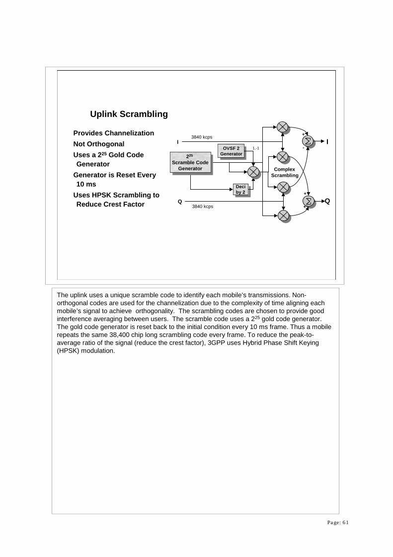
Page: 61
ComplexScrambling
I+
+
+
-OVSF 2Generator
1,-1
Deciby 2
I3840 kcps
225
Scramble CodeGenerator
Q3840 kcps
Q
Uplink Scrambling
Provides ChannelizationNot OrthogonalUses a 225 Gold Code Generator
Generator is Reset Every 10 ms
Uses HPSK Scrambling to Reduce Crest Factor
The uplink uses a unique scramble code to identify each mobile’s transmissions. Non-orthogonal codes are used for the channelization due to the complexity of time aligning each mobile’s signal to achieve orthogonality. The scrambling codes are chosen to provide good interference averaging between users. The scramble code uses a 225 gold code generator. The gold code generator is reset back to the initial condition every 10 ms frame. Thus a mobile repeats the same 38,400 chip long scrambling code every frame. To reduce the peak-to-average ratio of the signal (reduce the crest factor), 3GPP uses Hybrid Phase Shift Keying (HPSK) modulation.
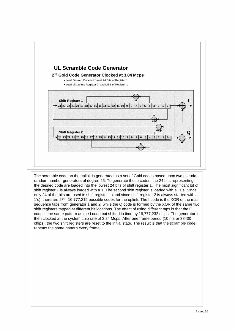
Page: 62
Shift Register 1
Shift Register 224 23 22 21 20 19 18 17 16 15 14 13 12 11 10 9 8 7 6 5 4 3 2 1 0
24 23 22 21 20 19 18 17 16 15 14 13 12 11 10 9 8 7 6 5 4 3 2 1 0I
Q
UL Scramble Code Generator225 Gold Code Generator Clocked at 3.84 Mcps
• Load Desired Code in Lowest 24 Bits of Register 1• Load all 1’s into Register 2, and MSB of Register 1
The scramble code on the uplink is generated as a set of Gold codes based upon two pseudo-random number generators of degree 25. To generate these codes, the 24 bits representing the desired code are loaded into the lowest 24 bits of shift register 1. The most significant bit of shift register 1 is always loaded with a 1. The second shift register is loaded with all 1’s. Since only 24 of the bits are used in shift register 1 (and since shift register 2 is always started with all 1’s), there are 224= 16,777,215 possible codes for the uplink. The I code is the XOR of the main sequence taps from generator 1 and 2, while the Q code is formed by the XOR of the same two shift registers tapped at different bit locations. The affect of using different taps is that the Q code is the same pattern as the I code but shifted in time by 16,777,232 chips. The generator is then clocked at the system chip rate of 3.84 Mcps. After one frame period (10 ms or 38400 chips), the two shift registers are reset to the initial state. The result is that the scramble code repeats the same pattern every frame.
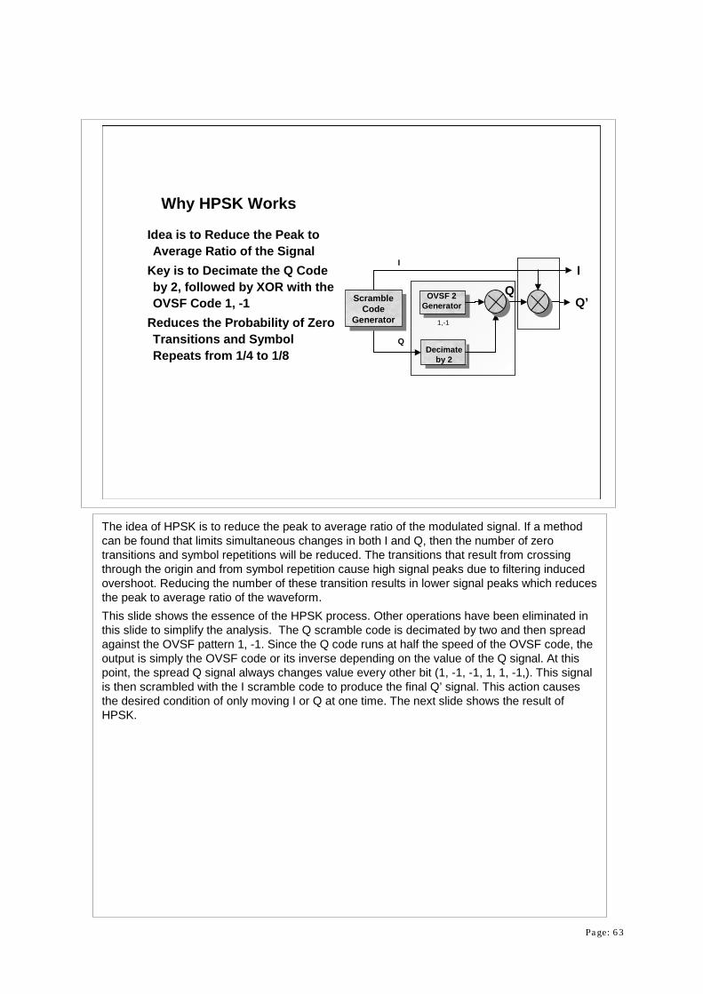
Page: 63
Q
OVSF 2Generator
1,-1
Decimateby 2
I
Scramble Code
Generator
Q’
I
Why HPSK Works
Idea is to Reduce the Peak to Average Ratio of the Signal
Key is to Decimate the Q Code by 2, followed by XOR with the OVSF Code 1, -1
Reduces the Probability of Zero Transitions and Symbol Repeats from 1/4 to 1/8
Q
The idea of HPSK is to reduce the peak to average ratio of the modulated signal. If a method can be found that limits simultaneous changes in both I and Q, then the number of zero transitions and symbol repetitions will be reduced. The transitions that result from crossing through the origin and from symbol repetition cause high signal peaks due to filtering induced overshoot. Reducing the number of these transition results in lower signal peaks which reduces the peak to average ratio of the waveform. This slide shows the essence of the HPSK process. Other operations have been eliminated in this slide to simplify the analysis. The Q scramble code is decimated by two and then spread against the OVSF pattern 1, -1. Since the Q code runs at half the speed of the OVSF code, theoutput is simply the OVSF code or its inverse depending on the value of the Q signal. At this point, the spread Q signal always changes value every other bit (1, -1, -1, 1, 1, -1,). This signal is then scrambled with the I scramble code to produce the final Q’ signal. This action causes the desired condition of only moving I or Q at one time. The next slide shows the result of HPSK.

Page: 64
Result of HPSK Coding
In Each Symbol Change, Zero Crossings and Symbol Repeats Are NOT Allowed !
Next Two Bit Pair Has a 1/4 Chance of Zero Crossing or Symbol Repeat
I
QI
Possibilities Q
Possibilities Q
Patterns Q'
Patterns I/Q' Pairs
1 1, -1 1, -1 1, 1 ; 1, -11, 1 -1 -1, 1 -1, 1 1, 1 ; -1, 11 1, -1 -1, 1 -1, -1 ; -1, 1-1, -1 -1 -1, 1 1, -1 -1, 1 ; -1, -11 1, -1 1, 1 1, 1 ; -1, 11, -1 -1 -1, 1 -1, -1 1, -1 ; -1, -11 1, -1 -1, -1 -1, -1 ; 1, -1-1, 1 -1 -1, 1 1, 1 -1, 1 ; 1, 1
1
1
-1
-1
Q
OVSF 2Generator
1,-1
Decimateby 2
IScramble
Code Generator
Q’
I
Q
This slide shows the possible combination of the I and Q’ scramble codes after HPSK processing. The easiest method to analyze HPSK , is to examine the possibilities in groups of two bits. The first column in the table shows all four of the possible I scramble code patterns. For each pair of bits, the Q scramble code after OVSF spreading will always be either 1, -1, or -1, 1. The second column shows these two Q pattern possibilities. The third column then shows the final Q’ patterns for both Q cases after multiplying them by the I pattern. The final column shows the I/Q pairs that can result. If you analyze the transitions for each case, you will find that zero crossings and symbol repetitions are not allowed (to achieve minimum overshoot). As you can see, either only I or Q changes which produces the minimum energy change.However, on the boundary with the next two bit group, zero crossings or symbol repetitions can occur. In this case, a zero crossing or symbol repetition with random data has a one out of four probability. Thus HPSK eliminates the zero crossings and symbol repetitions for every other symbol change.

Page: 65
HPSK OVSF Code RequirementsTo Preserve the Benefits of HPSK:
• OVSF Codes Must be Used that Do NOT Have Single Bit Value Changes• Examples that Meet Criteria:
• 1, 1, 1, 1, -1, -1, -1, -1• 1, 1, -1, -1
• Examples that Do NOT Meet Criteria:• 1, -1
In order to preserve the reduction in zero crossings and reduced peaks provided by HPSK, the OVSF codes selected for the various mobile channels must have certain bit patterns. The basic requirement is that the OVSF codes must have patterns that repeat bits at least twice before changing value. For example, the OVSF code 1, 1, -1, -1 works since it repeats values twice before changing. This repetition preserves the benefits of HPSK.

Page: 66
Shift Register 103 2 14567
2
03 2 14567
2
Shift Register 2 Mod 4
Shift Suspend afterevery 256-th Chipcycle
03 2 14567Shift Register 3
-+3 -+3
-+2-+3
Uplink Short Code ScramblerOptionally, Short Codes can Replace the Long CodesEnables Joint Detection in the Base Station
An alternative approach is to use short uplink scrambling codes instead of the long uplink scrambling codes. These codes are used when the base station is equipped with a joint detection receiver. These codes are designed to provide more stable cross correlation properties between individual mobiles on the uplink than the long scramble codes provide. These codes are 256 chips in length. The initial state of the three shift registers is the same 24 bit code word defined as the initial state of the long scramble code generator. Shift register 1 uses the 8 most significant bits of the 24 bit code word and shift register 2 uses the middle 8 bit of the 24 bit code word. Shift register 3 uses the least 8 significant bits of the 24 bit code word which are then transformed into a different 8 bits by multiplying the value by two and then performing modulo 4 division.

Page: 67
Joint DetectionUplink Link is Non-Orthogonal Which Increases InterferenceJoint Detection:
• Base Station Decodes All Possible Channels for That Cell• Base Station Then Subtracts Interference from All Users Other Than the Desired Channel
Reduces Interference and Raises System CapacityVery High Computing Power Required
The idea with using the short scramble codes is to allow joint detection at the base station. Since the uplink mobiles all interfere with each other, a method to increase capacity is to somehow cancel out the power from all other mobiles except for the one being decoded. Joint detection is a method to perform such interference cancellation. The idea is to simultaneously detect all mobile signals in the base station and then subtract the energy of all of the unwanted channels when decoding a given channel. The short scramble codes are designed to have relatively stable cross correlation properties to enable this interference cancellation. As you can imagine, joint detection requires massive processing power. The benefit for this high hardware cost is increased capacity on the uplink (which is usually the limiting factor in system total capacity).

Page: 68
I
Q
SF=4
DPDCH3Data Bits
OVSFGenerator
3840 kcps
DPDCH1Data Bits
OVSFGenerator
3840 kcps
SF=4
SF=4
DPDCH2Data Bits
OVSFGenerator
3840 kcps
DPCCHData Bits
OVSFGenerator
3840 kcps
SF=256
Q
Gain
Q
Gain
Gain
I
Gain
ComplexScrambling
I
+
+
+
-OVSF 2Generator
1,-1
Deciby 2
3840 kcps
225
Scramble CodeGenerator
Q 3840 kcps
Q
Up to 6 DPDCHs are Allowed
Uplink Higher Rate Configuration
If the total data rate of the transport channels in use exceeds the capacity of a single DPDCH, then additional DPDCHs can be added to accommodate the required data rate. These additional DPDCHs are allocated to the I and Q branches so as to balance the loaded on each branch. The maximum number of DPDCHs allowed on a single mobile is 6. If more than one DPDCHs are used, then all DPDCHs use a OVSF code with its spread factor equal to 4. At first this seems impossible, since up to 6 DPDCHs are allowed and at SF=4 there are only four codes. However, since these 6 channels are alternately placed on the I or Q branches (remember the I and Q channels are orthogonal), the OVSF codes can be reused on I and Q without creating interference. A single DPCCH is used no matter how many DPDCHs may be in use. Of course, adding many high data rate channels will quickly consume the total capacity of the uplink.

Page: 69
OVSF Code Tree
S.F. = 16
S.F. = 1 1
1,-1 1, 1S.F. = 2
S.F. = 4
S.F. = 8
1,-1, 1, -11,-1, -1, 1 1, 1, 1, 11, 1,- 1, -1
If this Code is Used,all Others Below itCannot Be Used
Multi-Rate Orthogonal Codes
The uplink is also subject to the limitations of usable OVSF codes as the Spread Factor is changed. If a very high rate DPDCH is operating, then the higher S.F. OVSF codes lower on the code code on that branch cannot be used. Remember that a further constraint is that OVSF codes with alternating bit patterns cannot be used since they remove the benefits of HPSK modulation. Fortunately, in most cases there are sufficient OVSF codes to handle multipleDPDCHs.

Page: 70
Call ProcessingMobile SynchronizationRead Broadcast ChannelMobile Initial Access:
• Base Station Page, Mobile Response• Mobile Initiated Call
Move to DPDCH/DPCCHSoft Handoff
To assist understanding of how the 3GPP system will function in actual use, the final section of this paper walks through a number of common systems procedures. This will include mobile synchronization, reading system parameters, initial mobile network access, DPDCH/DPCCH assignment, and soft handoff.

Page: 71
One Timeslot = 625 usec
PCCPCH
P-SCH
S-SCH PCCPCH
P-SCH
S-SCH PCCPCH
P-SCH
S-SCHBase 1
PCCPCH PCCPCH
P-SCH
S-SCH PCCPCH
P-SCH
S-SCH
P-SCH
S-SCHBase 2
PCCPCH
P-SCH
S-SCH PCCPCH
P-SCH
S-SCHPCCPCHBase 3
Mobile Searcher
Base 1
Base 2
Base 3
Mobile Initial Search
When a 3GPP mobile is powered on, it must find and synchronize to the most appropriate base station before it can receive pages or place mobile initiated calls. The first task for the mobile is to find all receivable primary SCH channels. At this point the mobile station has no timing reference at all. The mobile searches for the Primary Sync channel code which is transmitted during the first 10% of each timeslot. Since the 3GPP system is completely unsynchronized, the Primary SCH signal from each base station will be received at arbitrary time offsets. Once all of the receivable primary SCHs have been located, the mobile selects the strongest assuming that it probably is the closest base station. In this example, the mobile would select Base Station 1 since it provides the strongest signal.

Page: 72
Mobile SynchronizationFind and Time Sync to Primary SCH Chip RateFind and Decode Secondary SCH
• Determine Which of the 64 Possible Code Patterns the Secondary SCH is Sending
Begin Search for which of the 8 Possible Scrambling Codes the Base Station is Using Within the Code Group Defined by the Secondary SCH
Once the strongest cell is selected, the mobile time synchronizes to the primary SCH to align to the 3.84 Mcps chip rate and the 10 ms frame clock. Once this basic timing is established, the mobile can then search for the secondary SCH. To find the secondary SCH, the mobile must find which of the 64 possible code patterns the secondary SCH is transmitting. Once the pattern is found, the mobile can begin the search process to find which of the 8 possible scrambling codes the base station is using. Remember that the secondary SCH code pattern reduces the search down to the 8 scrambling codes that are associated with the secondary SCH code pattern. The mobile station searches for this scrambling code on the Primary C-CPICH that carries the BCH (Broadcast Channel).

Page: 73
Read Broadcast ChannelOnce Scrambling Code is Determined, Decode the Broadcast Channel (BCH)
BCH Messages Provide System Specific Information and Cell Parameters Required for Proper Operation
Cell May Require RegistrationOnce Complete, Mobile Enters Sleep ModeReads PICH to Determine if it Needs to Read PCHMonitors the PCH or FACH for Page
At this point, once the mobile has found the scrambling code, it can begin to decode channels from that base station. The mobile uses this timing information to decode the BCH. The BCH transmits the system specific information and cell specific information needed by the mobile to successfully access the system. For example, some of this information includes which signature and scramble code to use for the PRACH preamble, the scramble code to use for the PRACH message, and the timing of the access slots. The BCH may also indicate if the mobile needs to register with the network. After registration, the mobile then enters sleep mode to conserve battery life. In sleep mode, the mobile station powers down its receiver until specific times when a page from the base station for that mobile will occur. Just before the next active slot for a given mobile, the mobile first reads the PICH (Page Indicator) to determine if the next paging slot contains a page. If the indicator is positive, the mobile must remain awake to read the next paging slot. If the indicator is negative, the mobile station returns to sleep mode until the next slot.

Page: 74
Message Burst10 ms
1.33 ms Access Slots
1.067 msPreamble
1.067 msPreamble
Mobile onUplink
Base onDownlink
1.067 msAICH
1/2 Slot Offset0.667 ms
Mobile Initiated CallSends PRACH Preamble, Waits for AICH ResponseSends PRACH MessageResponse on PCH To Get DPDCH/DPCCH Assignment
If the user decides to place a call, the mobile sends a PRACH preamble that uses the proper signature and spreading code for that base station. Depending on the access slot timing of the cell, the mobile will continue sending preambles until it detects a response from the base station on the AICH (Acquisition Indication Channel). When the base station detects a preamble that matches its designated signature and scramble code, the base station transmits the AICH. The AICH indicates to the mobile that it’s PRACH was heard and that it is allowed to send the message portion of the PRACH. The mobile then transmits the message portion of the PRACH to the base station. The message part of the PRACH contains the signaling data required to establish the call. The PRACH uses the same construct of 15 slots every 20 ms as the AICH. The PRACH slots are timed to precede the PRACH slots by 1/2 slot (0.667 ms). The spacing of successive preambles, the spacing of the AICH from a preamble, and the spacing of the beginning of the last preamble to the message portion of a PRACH is set by the AICH Transmission Timing parameter:
∆T between preambles ∆T Preamble to AICH ∆Τ Last Preamble to Message AICH_Transmission_Timing = 0 at least 3 slots 1.5 slots 3 slots. AICH_Transmission_Timing = 1 at least 4 slots 2.5 slots
4 slots.

Page: 75
Soft HandoffMobile Searches for Other Cells - looks for Sync ChannelReports Candidate Cells to SystemReceives Assignment for Soft Handoff from NetworkMust Determine System Frame Number from Each Cell to Properly Time Align Each Cell’s Transmissions
The mobile searches for other cells by looking for the Primary and Secondary Sync channels. Once any found cells exceed a certain threshold, the mobile reports their level back to the system. The network then initiates a soft handoff if resources are available. One complication for the 3GPP system is that cells may be running with different system frame numbers (unsynchronized operation). Some mechanism is required to give the mobile knowledge of the system frame number so that data received from each base station can be correctly summed together from the rake receivers. The System Frame Number (SFN) is multiplexed with the BCH transport channel and is carried over-the-air on the P-CCPCH.

Page: 76
Conclusions3GPP is a Complex, CDMA Based Wireless SystemOffers Increased Capacity over GSMSupports Packet Data up to High RatesWill Enable a Myriad of New, Data Based Wireless Applications
As the standard evolves, the 3GPP WCDMA system will expand its capabilities including operation on the IS-41 networks used in North America. The 3GPP WCDMA system is complex and offers many new features not found in second generation or even 2.5 generation digital wireless systems. It has higher capacity than existing systems like GSM and supports true packet operation up to fairly high data rates. These capabilities will allow 3GPP WCDMA to support a myriad of new services that will continue to propel the expansion of wireless communication for years to come.

专注于微波、射频、天线设计人才的培养 易迪拓培训 网址:http://www.edatop.com
射 频 和 天 线 设 计 培 训 课 程 推 荐
易迪拓培训(www.edatop.com)由数名来自于研发第一线的资深工程师发起成立,致力并专注于微
波、射频、天线设计研发人才的培养;我们于 2006 年整合合并微波 EDA 网(www.mweda.com),现
已发展成为国内最大的微波射频和天线设计人才培养基地,成功推出多套微波射频以及天线设计经典
培训课程和 ADS、HFSS 等专业软件使用培训课程,广受客户好评;并先后与人民邮电出版社、电子
工业出版社合作出版了多本专业图书,帮助数万名工程师提升了专业技术能力。客户遍布中兴通讯、
研通高频、埃威航电、国人通信等多家国内知名公司,以及台湾工业技术研究院、永业科技、全一电
子等多家台湾地区企业。
易迪拓培训课程列表:http://www.edatop.com/peixun/rfe/129.html
射频工程师养成培训课程套装
该套装精选了射频专业基础培训课程、射频仿真设计培训课程和射频电
路测量培训课程三个类别共 30 门视频培训课程和 3 本图书教材;旨在
引领学员全面学习一个射频工程师需要熟悉、理解和掌握的专业知识和
研发设计能力。通过套装的学习,能够让学员完全达到和胜任一个合格
的射频工程师的要求…
课程网址:http://www.edatop.com/peixun/rfe/110.html
ADS 学习培训课程套装
该套装是迄今国内最全面、最权威的 ADS 培训教程,共包含 10 门 ADS
学习培训课程。课程是由具有多年 ADS 使用经验的微波射频与通信系
统设计领域资深专家讲解,并多结合设计实例,由浅入深、详细而又
全面地讲解了 ADS 在微波射频电路设计、通信系统设计和电磁仿真设
计方面的内容。能让您在最短的时间内学会使用 ADS,迅速提升个人技
术能力,把 ADS 真正应用到实际研发工作中去,成为 ADS 设计专家...
课程网址: http://www.edatop.com/peixun/ads/13.html
HFSS 学习培训课程套装
该套课程套装包含了本站全部 HFSS 培训课程,是迄今国内最全面、最
专业的HFSS培训教程套装,可以帮助您从零开始,全面深入学习HFSS
的各项功能和在多个方面的工程应用。购买套装,更可超值赠送 3 个月
免费学习答疑,随时解答您学习过程中遇到的棘手问题,让您的 HFSS
学习更加轻松顺畅…
课程网址:http://www.edatop.com/peixun/hfss/11.html
`

专注于微波、射频、天线设计人才的培养 易迪拓培训 网址:http://www.edatop.com
CST 学习培训课程套装
该培训套装由易迪拓培训联合微波 EDA 网共同推出,是最全面、系统、
专业的 CST 微波工作室培训课程套装,所有课程都由经验丰富的专家授
课,视频教学,可以帮助您从零开始,全面系统地学习 CST 微波工作的
各项功能及其在微波射频、天线设计等领域的设计应用。且购买该套装,
还可超值赠送 3 个月免费学习答疑…
课程网址:http://www.edatop.com/peixun/cst/24.html
HFSS 天线设计培训课程套装
套装包含 6 门视频课程和 1 本图书,课程从基础讲起,内容由浅入深,
理论介绍和实际操作讲解相结合,全面系统的讲解了 HFSS 天线设计的
全过程。是国内最全面、最专业的 HFSS 天线设计课程,可以帮助您快
速学习掌握如何使用 HFSS 设计天线,让天线设计不再难…
课程网址:http://www.edatop.com/peixun/hfss/122.html
13.56MHz NFC/RFID 线圈天线设计培训课程套装
套装包含 4 门视频培训课程,培训将 13.56MHz 线圈天线设计原理和仿
真设计实践相结合,全面系统地讲解了 13.56MHz线圈天线的工作原理、
设计方法、设计考量以及使用 HFSS 和 CST 仿真分析线圈天线的具体
操作,同时还介绍了 13.56MHz 线圈天线匹配电路的设计和调试。通过
该套课程的学习,可以帮助您快速学习掌握 13.56MHz 线圈天线及其匹
配电路的原理、设计和调试…
详情浏览:http://www.edatop.com/peixun/antenna/116.html
我们的课程优势:
※ 成立于 2004 年,10 多年丰富的行业经验,
※ 一直致力并专注于微波射频和天线设计工程师的培养,更了解该行业对人才的要求
※ 经验丰富的一线资深工程师讲授,结合实际工程案例,直观、实用、易学
联系我们:
※ 易迪拓培训官网:http://www.edatop.com
※ 微波 EDA 网:http://www.mweda.com
※ 官方淘宝店:http://shop36920890.taobao.com
专注于微波、射频、天线设计人才的培养
官方网址:http://www.edatop.com 易迪拓培训 淘宝网店:http://shop36920890.taobao.com