rmx508dfx - quickstart guide - v1 - altoproaudio.com - quickstart g… · 3 box contents y...
TRANSCRIPT
RMX508DFX
QUICKSTART GUIDE ENGLISH


3
BOX CONTENTS RMX508DFX Power cable Quickstart Guide Safety Instructions & Warranty Information booklet
CONNECTION DIAGRAM
PREPRE
AUXAUXSENDSEND
+10dB-
POSTPOST
- +10dB
LEVELLEVEL- +10dB
PREPRE
AUXAUXSENDSEND
+10dB-
2 F XPOSTPOST
- +10dB
LEVELLEVEL- +10dB
PREPRE
AUXAUXSENDSEND
+10dB-
2 F XPOSTPOST
- +10dB
LEVELLEVEL- +10dB
PREPRE
AUXAUXSENDSEND
+10dB-
2 F XPOSTPOST
- +10dB
LEVELLEVEL- +10dB
PREPRE
AUXAUXSENDSEND
+10dB-
2 F XPOSTPOST
- +10dB
LEVELLEVEL- +10dB
PREPRE
AUXAUXSENDSEND
+10dB-
2 F XPOSTPOST
- +10dB
LEVELLEVEL- +10dB
LINELINEBALBAL
MICMICBALBAL
LINELINEBALBAL
MICMICBALBAL
MICMICBALBAL
LINELINEBALBAL
MICMICBALBAL
LINELINEBALBAL
LINELINEBALBAL
LINELINEBALBAL
MICMICBALBAL
HIHI12kHz12kHz
-15
MIDMID2.5kHz2.5kHz
-15
LOWLOW80Hz80Hz
-15
LOWLOW80Hz80Hz
-15
-15
MIDMID2.5kHz2.5kHz
LOWLOW80Hz80Hz
-15
MIDMID2.5kHz2.5kHz
-15
HIHI12kHz12kHz
-15 -15
HIHI12kHz12kHz
HIHI12kHz12kHz
-15
MIDMID2.5kHz2.5kHz
-15
LOWLOW80Hz80Hz
-15
LOWLOW80Hz80Hz
-15
MIDMID2.5kHz2.5kHz
-15
MIDMID2.5kHz2.5kHz
LOWLOW80Hz80Hz
-15
-15
HIHI12kHz12kHz
-15
HIHI12kHz12kHz
-15
MICMICBALBAL
MICMICBALBAL
MICMICBALBAL STEREO RTNSTEREO RTN
AUX OUTAUX OUT
FOOTSWITCHFOOTSWITCH
HIHI12kHz12kHz
-15
MIDMID2.5kHz2.5kHz
-15
-15
HIHI12kHz12kHz
-15
MIDMID2.5kHz2.5kHz
-15
-15
100FX TO MAINFX TO MAIN
100
POWERPOWER
FEEDBACKFEEDBACKTERMINATORTERMINATOR
PHANTOMPHANTOM
+10+10
0dB0dB
-10-10
-30-30
1515
9
0
9
1515
10dB10dB
PREPRE
AUXAUXSENDSEND
+10dB-
PREPRE
AUXAUXSENDSEND
+10dB-
2 F XPOSTPOST
- +10dB
2 F XPOSTPOST
- +10dB
LEVELLEVEL- +10dB
LEVELLEVEL- +10dB
1515
9
0
9
1515
5050 100100 250250 500500 1K1K 2K52K5 5K5K 8K8K 16K16K
1515
9
0
9
1515
1515
9
0
9
1515
5050 100100 250250 500500 1K1K 2K52K5 5K5K 8K8K 16K16K
+ +
-10-10
-30-30
+10+10
10dB10dB
-20dB PAD-20dB PAD -20dB PAD-20dB PAD -20dB PAD-20dB PAD -20dB PAD-20dB PAD -20dB PAD-20dB PAD -20dB PAD-20dB PAD -20dB PAD-20dB PAD-20dB PAD-20dB PAD
LEFTLEFT RIGHTRIGHT
BALBALBALBAL
LEFTLEFT RIGHTRIGHT
PANPAN
LEFTLEFT RIGHTRIGHT
PANPAN
LEFTLEFT RIGHTRIGHT
PANPAN
LEFTLEFT RIGHTRIGHT
PANPAN
LEFTLEFT RIGHTRIGHT
PANPAN
LEFTLEFT RIGHTRIGHT
PANPAN
LEFTLEFT RIGHTRIGHT
1
NEW
1
NEW
1
NEW
1
NEW
1
NEW
1
NEW
1
NEW
1
NEW
INSTALLATION AND CONNECTION Follow the procedure below to have a signal processed for each channel: 1. Turn down all Input and output gain controls. 2. Connect phantom powered microphones before switching on the +48 Volt phantom power switch. 3. Set the output level of your RMX508DFX at no more than 75%. 4. Set the MAIN level at no more than 50%. In this way you will be able to hear the signal by connecting a
pair of headphones or powered speakers. 5. Position EQ controls on the middle position. 6. Position panoramic (PAN) control on center position. 7. Increase the input gain properly for maintaining the good headroom and ideal dynamic range. 8. Depending on the actual application, slowly turn the input and output level controls to obtain the
maximum gain before distortion. 9. Repeat the same sequence for all input channels. The main LED meter may move up into the red LED
section. If this is the case, adjust the overall output level using the MAIN control to avoid this.
Notes: Microphones, monitors, amplifier, speakers, cables, etc. are not included. To reduce electrical hum at high gain settings, keep the mixer's power supply away from your guitar cable and
the mixer's channel inputs. To use an external effects rack unit, compressor, etc., use a Y-cable (1/4" stereo to two 1/4" mono) to connect
the AUX OUT to the left and right inputs your external device. Connect the outputs of your external device to the mixers Stereo Return.
4
FRONT PANEL
PREPRE
AUXAUXSENDSEND
+10dB-
POSTPOST
- +10dB
LEVELLEVEL- +10dB
PREPRE
AUXAUXSENDSEND
+10dB-
2 F XPOSTPOST
- +10dB
LEVELLEVEL- +10dB
PREPRE
AUXAUXSENDSEND
+10dB-
2 F XPOSTPOST
- +10dB
LEVELLEVEL- +10dB
PREPRE
AUXAUXSENDSEND
+10dB-
2 F XPOSTPOST
- +10dB
LEVELLEVEL- +10dB
PREPRE
AUXAUXSENDSEND
+10dB-
2 F XPOSTPOST
- +10dB
LEVELLEVEL- +10dB
PREPRE
AUXAUXSENDSEND
+10dB-
2 F XPOSTPOST
- +10dB
LEVELLEVEL- +10dB
LINELINEBALBAL
MICMICBALBAL
LINELINEBALBAL
MICMICBALBAL
MICMICBALBAL
LINELINEBALBAL
MICMICBALBAL
LINELINEBALBAL
LINELINEBALBAL
LINELINEBALBAL
MICMICBALBAL
HIHI12kHz12kHz
-15
MIDMID2.5kHz2.5kHz
-15
LOWLOW80Hz80Hz
-15
LOWLOW80Hz80Hz
-15
-15
MIDMID2.5kHz2.5kHz
LOWLOW80Hz80Hz
-15
MIDMID2.5kHz2.5kHz
-15
HIHI12kHz12kHz
-15 -15
HIHI12kHz12kHz
HIHI12kHz12kHz
-15
MIDMID2.5kHz2.5kHz
-15
LOWLOW80Hz80Hz
-15
LOWLOW80Hz80Hz
-15
MIDMID2.5kHz2.5kHz
-15
MIDMID2.5kHz2.5kHz
LOWLOW80Hz80Hz
-15
-15
HIHI12kHz12kHz
-15
HIHI12kHz12kHz
-15
MICMICBALBAL
MICMICBALBAL
MICMICBALBAL STEREO RTNSTEREO RTN
AUX OUTAUX OUT
FOOTSWITCHFOOTSWITCH
HIHI12kHz12kHz
-15
MIDMID2.5kHz2.5kHz
-15
-15
HIHI12kHz12kHz
-15
MIDMID2.5kHz2.5kHz
-15
-15
100FX TO MAINFX TO MAIN
100
POWERPOWER
FEEDBACKFEEDBACKTERMINATORTERMINATOR
PHANTOMPHANTOM
+10+10
0dB0dB
-10-10
-30-30
1515
9
0
9
1515
10dB10dB
PREPRE
AUXAUXSENDSEND
+10dB-
PREPRE
AUXAUXSENDSEND
+10dB-
2 F XPOSTPOST
- +10dB
2 F XPOSTPOST
- +10dB
LEVELLEVEL- +10dB
LEVELLEVEL- +10dB
1515
9
0
9
1515
5050 100100 250250 500500 1K1K 2K52K5 5K5K 8K8K 16K16K
1515
9
0
9
1515
1515
9
0
9
1515
5050 100100 250250 500500 1K1K 2K52K5 5K5K 8K8K 16K16K
+ +
-10-10
-30-30
+10+10
10dB10dB
-20dB PAD-20dB PAD -20dB PAD-20dB PAD -20dB PAD-20dB PAD -20dB PAD-20dB PAD -20dB PAD-20dB PAD -20dB PAD-20dB PAD -20dB PAD-20dB PAD-20dB PAD-20dB PAD
LEFTLEFT RIGHTRIGHT
BALBALBALBAL
LEFTLEFT RIGHTRIGHT
PANPAN
LEFTLEFT RIGHTRIGHT
PANPAN
LEFTLEFT RIGHTRIGHT
PANPAN
LEFTLEFT RIGHTRIGHT
PANPAN
LEFTLEFT RIGHTRIGHT
PANPAN
LEFTLEFT RIGHTRIGHT
PANPAN
LEFTLEFT RIGHTRIGHT
1
NEW
1
NEW
1
NEW
1
NEW
1
NEW
1
NEW
1
NEW
1
NEW
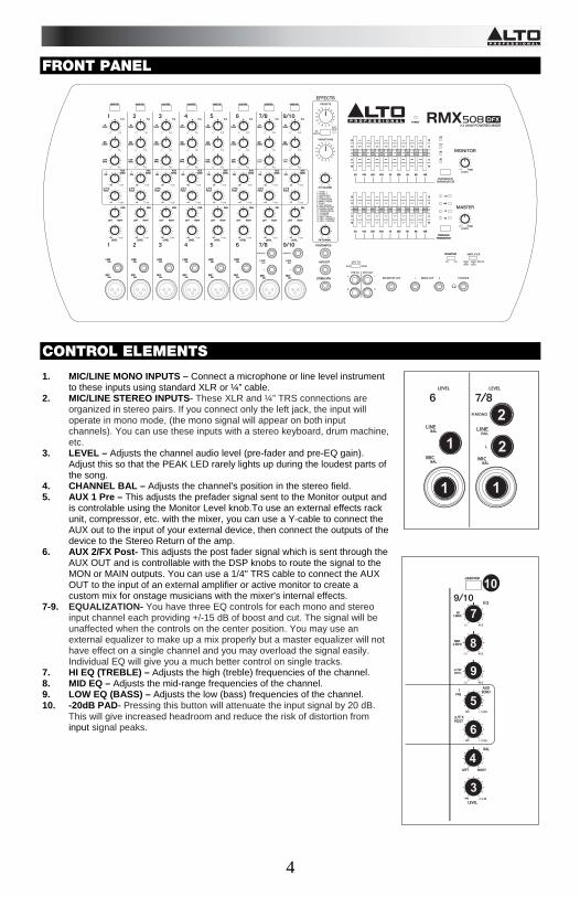
CONTROL ELEMENTS 1. MIC/LINE MONO INPUTS – Connect a microphone or line level instrument
to these inputs using standard XLR or ¼” cable. 2. MIC/LINE STEREO INPUTS- These XLR and ¼” TRS connections are
organized in stereo pairs. If you connect only the left jack, the input will operate in mono mode, (the mono signal will appear on both input channels). You can use these inputs with a stereo keyboard, drum machine, etc.
3. LEVEL – Adjusts the channel audio level (pre-fader and pre-EQ gain). Adjust this so that the PEAK LED rarely lights up during the loudest parts of the song.
4. CHANNEL BAL – Adjusts the channel's position in the stereo field. 5. AUX 1 Pre – This adjusts the prefader signal sent to the Monitor output and
is controlable using the Monitor Level knob.To use an external effects rack unit, compressor, etc. with the mixer, you can use a Y-cable to connect the AUX out to the input of your external device, then connect the outputs of the device to the Stereo Return of the amp.
6. AUX 2/FX Post- This adjusts the post fader signal which is sent through the AUX OUT and is controllable with the DSP knobs to route the signal to the MON or MAIN outputs. You can use a 1/4" TRS cable to connect the AUX OUT to the input of an external amplifier or active monitor to create a custom mix for onstage musicians with the mixer’s internal effects.
7-9. EQUALIZATION- You have three EQ controls for each mono and stereo input channel each providing +/-15 dB of boost and cut. The signal will be unaffected when the controls on the center position. You may use an external equalizer to make up a mix properly but a master equalizer will not have effect on a single channel and you may overload the signal easily. Individual EQ will give you a much better control on single tracks.
7. HI EQ (TREBLE) – Adjusts the high (treble) frequencies of the channel. 8. MID EQ – Adjusts the mid-range frequencies of the channel. 9. LOW EQ (BASS) – Adjusts the low (bass) frequencies of the channel. 10. -20dB PAD- Pressing this button will attenuate the input signal by 20 dB.
This will give increased headroom and reduce the risk of distortion from input signal peaks.
HIHI12kHz12kHz
-15
MIDMID2.5kHz2.5kHz
-15
-15
PREPRE
AUXAUXSENDSEND
+10dB-
2 F XPOSTPOST
- +10dB
LEVELLEVEL- +10dB
-20dB PAD-20dB PAD
LEFTLEFT RIGHTRIGHT
BALBAL
10
7
8
9
5
6
4
3
LEVELLEVEL
LINELINEBALBAL
MICMICBALBAL
MICMICBALBAL
LEVELLEVEL
1
NEW
1
NEW
1
1 1
2
2
5
18
20 2021 222323
2424
25
26
27
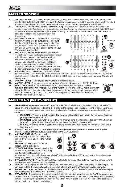
MASTER SECTION
11. STEREO GRAPHIC EQ: There are two graphic EQs each with 9 adjustable bands; one is for the MAIN mix
and the other is for the MONITOR mix. With the faders you can boost or cut the selected frequency by +/-15 dB at the indicated frequencies. When all faders are at the center position, the equalizer is disabled.
12. FEEDBACK TERMINATOR Button (MONITOR mix)- This button activates the feedback detection in the monitor signal path. Feedback will be identified at a certain frequency when the corresponding fader LED lights up. Feedback produces an unpleasant speaker "howling" or "whistling". In order to eliminate feedback, turn down the corresponding fader until feedback disappears.
13. MONITOR LEVEL LED Display- This LED display will show you the monitor output level. Make sure that the +10 LED only lights up occasionally. The optimal level is between -10 and 0 on the LED. If only the -30 LED lights up or doesn't come on, your S/N ratio will be degraded.
14. FEEDBACK TERMINATOR Button (MAIN mix)- This button activates the feedback detection function in the Main mix signal path. Feedback will be identified at a certain frequency when the corresponding fader LED lights up. Feedback produces an unpleasant speaker "howling" or "whistling". In order to eliminate feedback, turn down the corresponding fader until feedback disappears.
15. MAIN mix LEVEL LED Display- This LED display will show you the Main mix output level. Make sure that the +10 LED only lights up occasionally. The optimal level is between -10 and 0 on the LED. If only the -30 LED lights up or doesn't not come on your S/N ratio will be degraded.
16. MONITOR LEVEL – This adjusts the volume of the Monitor output. 17. MASTER LEVEL- This adjusts the overall volume of the MAIN output and HEADPHONE out. 18. PHANTOM POWER – This switch activates and deactivates phantom power. When
activated, phantom power supplies +48V to the XLR mic inputs and the LED above the switch will be lit. Please note that most dynamic microphones do not require phantom power, while most condenser microphones do. Consult your microphone’s documentation to find out whether it needs phantom power.
MASTER I/O (INPUT/OUTPUT) 19. AMPLIFIER Mode Switch- This switch provides three modes: MAIN/MAIN, MAIN/MONITOR and BRIDGE.
Select any one of these modes to route the signals to the corresponding jacks according to the speaker panel connection. This switch only affects the rear panel outputs. The front panels outputs are unaffected by this switch.
• MAIN/MAIN- When the switch is set to this, the amp will send the main mix to the rear panel Speakon jacks or the rear panel ¼” jacks.
• MAIN/MON- When the switch is set to this, the amp will send the main mix to the OUTPUT 1 Speakon jack and 1/4'”jack. The monitor mix will be sent to the OUTPUT 2 Speakon jack.
• BRIDGE- When the switch is set to this, the amp will send the main mix to the rear panel OUTPUT 2 Speakon jack.
20. MAIN OUTPUTS – These 1/4" line level outputs can be connected to powered speakers or an amplifier system. The level of these outputs is controlled by the Main Level knob.
21. MONITOR OUTPUT- This line level balanced output is used to connect the input of an external amplifier or powered speaker.
22. PHONES – Connect your 1/4" stereo headphones to this output.
23. 2-TRACK INPUTS – Connect these to the outputs of an external sound source using standard stereo RCA cables (sold separately). You can send this to channels 9/10 (using the 2-TRACK to 9/10 switch) or to the main outputs (using the 2-TRACK TO MAIN switch).
24. 2-TRACK OUTPUTS – You may connect these outputs to the inputs of an external recording device using a standard stereo RCA cable (sold separately).
25. AUX OUT- This outputs the line level signal sent from a channel’s AUX1 Pre knob to the Monitor Output. You can use it to feed the inputs of another stereo multi-effects unit (using a Y-type cable sold separately).
26. STEREO RETURN- This stereo jack is used to route a stereo signal to the Main, Monitor and Phones outputs by adjusting the FX TO MAIN and FX TO MON knobs.
27. 2-TRACK TO– If you position this switch to the left you will route the signal fed into the TAPE IN sockets into CH9~10 path, and the signal will be affected by channel level control, channel EQ, DSP send, and MAIN level control. Positioning this switch to the right will route the TAPE IN signal into Main mix bus. In this case signal will be affected only by Main level control.
11
11
12
13
14
15
16
17
6
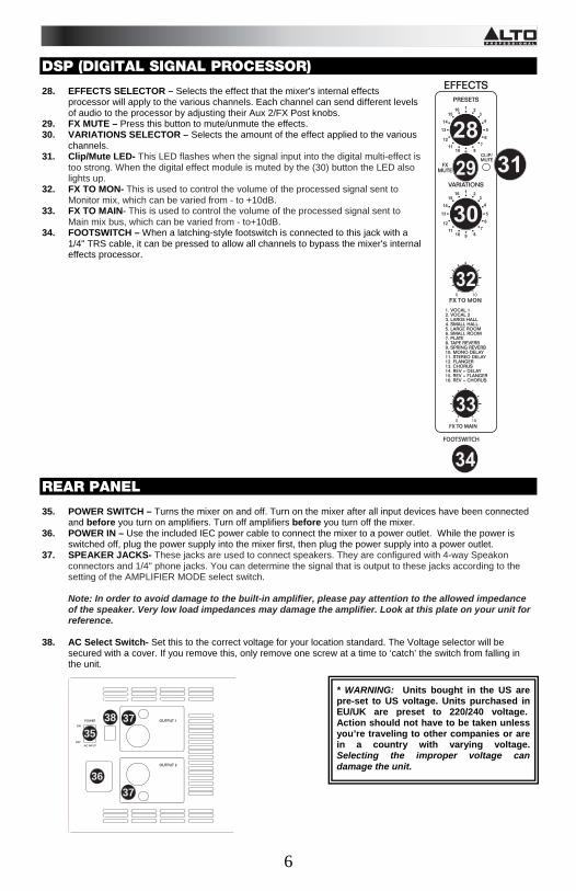
DSP (DIGITAL SIGNAL PROCESSOR)
28. EFFECTS SELECTOR – Selects the effect that the mixer's internal effects
processor will apply to the various channels. Each channel can send different levels of audio to the processor by adjusting their Aux 2/FX Post knobs.
29. FX MUTE – Press this button to mute/unmute the effects. 30. VARIATIONS SELECTOR – Selects the amount of the effect applied to the various
channels. 31. Clip/Mute LED- This LED flashes when the signal input into the digital multi-effect is
too strong. When the digital effect module is muted by the (30) button the LED also lights up.
32. FX TO MON- This is used to control the volume of the processed signal sent to Monitor mix, which can be varied from - to +10dB.
33. FX TO MAIN- This is used to control the volume of the processed signal sent to Main mix bus, which can be varied from - to+10dB.
34. FOOTSWITCH – When a latching-style footswitch is connected to this jack with a 1/4" TRS cable, it can be pressed to allow all channels to bypass the mixer's internal effects processor.
REAR PANEL
35. POWER SWITCH – Turns the mixer on and off. Turn on the mixer after all input devices have been connected and before you turn on amplifiers. Turn off amplifiers before you turn off the mixer.
36. POWER IN – Use the included IEC power cable to connect the mixer to a power outlet. While the power is switched off, plug the power supply into the mixer first, then plug the power supply into a power outlet.
37. SPEAKER JACKS- These jacks are used to connect speakers. They are configured with 4-way Speakon connectors and 1/4" phone jacks. You can determine the signal that is output to these jacks according to the setting of the AMPLIFIER MODE select switch. Note: In order to avoid damage to the built-in amplifier, please pay attention to the allowed impedance of the speaker. Very low load impedances may damage the amplifier. Look at this plate on your unit for reference.
38. AC Select Switch- Set this to the correct voltage for your location standard. The Voltage selector will be secured with a cover. If you remove this, only remove one screw at a time to ‘catch’ the switch from falling in the unit.
* WARNING: Units bought in the US are pre-set to US voltage. Units purchased in EU/UK are preset to 220/240 voltage. Action should not have to be taken unless you’re traveling to other companies or are in a country with varying voltage. Selecting the improper voltage can damage the unit.
37
37
3835
36
FOOTSWITCHFOOTSWITCH
100FX TO MAINFX TO MAIN
100
28
3129
30
32
33
34

7
EFFECTS TO HEAR THE EFFECTS ON A CHANNEL: Use the Effects Selector to choose one of the effects below, adjust the parameter with the Variations Selector, then turn up the Aux 2/FX Post knob for that channel.
# PRESET DESCRIPTION PARAMETER RANGE
1 VOCAL 1 Reverb, simulating a room with a small delay time. Decay time Pre-delay
0.8~1.1s 0~79ms
2 VOCAL 2 Reverb, simulating a small space with a small delay time.
Decay time Pre-delay
0.8~2.5s 0~79ms
3 LARGE HALL Reverb, simulating a large acoustic space. Decay time Pre-delay 3.6~5.4s
23~55ms
4 SMALL HALL Reverb, simulating the acoustics of a stage space. Decay time Pre-delay
1.0~2.9s 20~45ms
5 LARGE ROOM Reverb, simulating a studio with many early reflections. Decay time Pre-delay 2.9~4.5s
23~55ms
6 SMALL ROOM Reverb, simulating a bright studio room. Decay time Pre-delay
0.7~2.1s 20~45ms
7 PLATE Simulates bright plate reverb. Decay time Pre-delay 0.6~6.1s
10ms
8 TAPE REVERB Simulates classic tape delay created by multiple playback heads.
Decay time Pre-delay
1.3~5.4 0~84ms
9 SPRING REVERB Simulates the lightly stretched sound of spring reverb from analog transducers.
Decay time Pre-delay 1.3~5.4s
0~84ms
10 MONO DELAY Reproduces the signal after a small period of time. Delay period 60~650ms
11 STEREO DELAY Reproduces the signal after a small period of time with a slight difference between the two stereo channels.
Delay period Feedback
210~400ms 37~73%
12 FLANGER Classic stereo flanging effect, similar to a jet plane taking off. Rate 0.16~2.79Hz
13 CHORUS Simulates the full, complex, watery sound of several instruments playing the same thing. Rate 0.5~5Hz
14 REVERB+DELAY Delay effect with room reverb. Delay period Reverse decay time
211~375ms 1.0~2.9s
15 REVERB+FLANGER Stereo flanger effect with room reverb. Flanger rate Reverse decay time 0.16~2.52Hz
16 REVERB+CHORUS Stereo chorus effect with room reverb. Chorus rate Reverse decay time
0.5~4.74Hz 1.5~2.9s

8
AUDIO LINE/MIC CONNECTIONS You can connect unbalanced equipment to balanced inputs and outputs. Simply follow these schematics.
! Caution: Do not connect the rear panel speaker level ¼” outputs to anything other than a passive
loudspeaker. Connecting this output to a line line/Mic level input may damage your equipment.
9
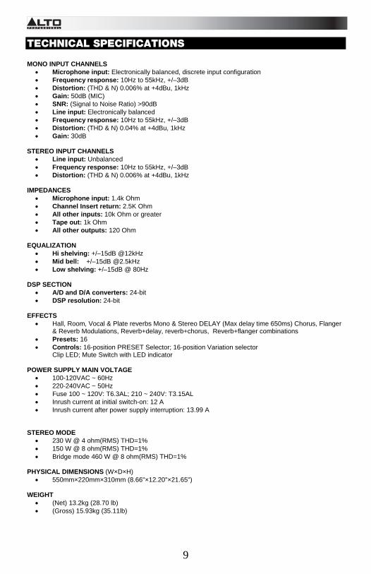
TECHNICAL SPECIFICATIONS MONO INPUT CHANNELS
• Microphone input: Electronically balanced, discrete input configuration • Frequency response: 10Hz to 55kHz, +/–3dB • Distortion: (THD & N) 0.006% at +4dBu, 1kHz • Gain: 50dB (MIC) • SNR: (Signal to Noise Ratio) >90dB • Line input: Electronically balanced • Frequency response: 10Hz to 55kHz, +/–3dB • Distortion: (THD & N) 0.04% at +4dBu, 1kHz • Gain: 30dB
STEREO INPUT CHANNELS
• Line input: Unbalanced • Frequency response: 10Hz to 55kHz, +/–3dB • Distortion: (THD & N) 0.006% at +4dBu, 1kHz
IMPEDANCES
• Microphone input: 1.4k Ohm • Channel Insert return: 2.5K Ohm • All other inputs: 10k Ohm or greater • Tape out: 1k Ohm • All other outputs: 120 Ohm
EQUALIZATION
• Hi shelving: +/–15dB @12kHz • Mid bell: +/–15dB @2.5kHz • Low shelving: +/–15dB @ 80Hz
DSP SECTION
• A/D and D/A converters: 24-bit • DSP resolution: 24-bit
EFFECTS
• Hall, Room, Vocal & Plate reverbs Mono & Stereo DELAY (Max delay time 650ms) Chorus, Flanger & Reverb Modulations, Reverb+delay, reverb+chorus, Reverb+flanger combinations
• Presets: 16 • Controls: 16-position PRESET Selector; 16-position Variation selector
Clip LED; Mute Switch with LED indicator POWER SUPPLY MAIN VOLTAGE
• 100-120VAC ~ 60Hz • 220-240VAC ~ 50Hz • Fuse 100 ~ 120V: T6.3AL; 210 ~ 240V: T3.15AL • Inrush current at initial switch-on: 12 A • Inrush current after power supply interruption: 13.99 A
STEREO MODE
• 230 W @ 4 ohm(RMS) THD=1% • 150 W @ 8 ohm(RMS) THD=1% • Bridge mode 460 W @ 8 ohm(RMS) THD=1%
PHYSICAL DIMENSIONS (W×D×H)
• 550mm×220mm×310mm (8.66"×12.20"×21.65") WEIGHT
• (Net) 13.2kg (28.70 lb) • (Gross) 15.93kg (35.11lb)


www.altoprofessional.com
MANUAL VERSION 1.2