robotic arm skate for stroke...
TRANSCRIPT
Robotic Arm Skate for Stroke Rehabilitation
Chee Kit Wong, Kimberlee Jordan and Marcus King Industrial Research Limited
New Zealand
Abstract— Upper limb paresis after stroke greatly affects the performance of Activities of Daily Living (ADL). Unfortunately, rehabilitation for upper limb impairment can have poor results. The current robot-assisted devices are expensive and not readily accessible for homecare. This paper presents the development of a low-cost tabletop robotic device for upper limb rehabilitation. Conceptually, patients perform computer-based goal-directed tasks using the robotic platform. Their progress is monitored and intervention, in the form of assistance or resistance, is introduced accordingly. A prototype platform is described. Experiments demonstrate the ability of the device to provide the necessary forces during movement exercises, in relation to task completion progress, device and target location. Appropriate exercises need to be developed before clinical trials can proceed.
Keywords-arm skate; augmented reality; stroke; rehabilitation; computer game; robot
I. INTRODUCTION The hand is the principal means by which an individual
interacts with objects and the environment, so the effect of loss of hand function on day to day activities is severe. Loss of hand function as a result of upper limb paresis after a stroke greatly reduces the probability that an individual can return home and to premorbid activities [1, 2]. Strength of the paretic upper limb is strongly related to measures of activity, although grip strength showed a moderate relationship with measures of activity and was not able to explain poor performance in ADL [3]. Unfortunately, the outcome of rehabilitation for an impaired upper limb is generally poor: fifty percent of stroke survivors have impairment of upper limb function, and of these only 15% can expect to regain function from a “traditional” physiotherapy program [4].
From the point of view of neuroplasticity, sensorimotor cortical representations and other signs of reorganization are most likely to accompany rewarded, goal-directed, task-specific practice [5]. Robotic-assisted therapy devices provide autonomous training where patients can engage in repeated and intense practice of goal-directed tasks, through computer-based virtual reality environments, leading to improvements in motor function [6-8]. Results of clinical trials using these systems to rehabilitate the upper limb are positive, with motor gains that correlate to clinical motor impairment scales such as the Fugl-Meyer [9], although improvement in ability to perform activities of daily living has yet to be shown [8].
However, there is a need to improve the cost-to-benefit ratio of robot-assisted therapy strategies and their effectiveness in extending motor gains to increased functional use of the impaired arm [10]. The rehabilitation interventions described
[8] require patient time on the devices of an average of 48 minutes per day for 8 weeks. A 6-axis robot can be expected to cost about US$60,000 and deployment (e.g. training, programming, adding tools etc.) may cost another US$200,000 [11]. Such a capital item, with a depreciation rate of say 15%, operating 40 hours per week, would need to be charged at US$19/hour, meaning that robotic arm treatment of one patient’s rehabilitation program will cost US$800 in capital depreciation alone, regardless of maintenance, running or therapist costs. If a low-cost (under US$1000) peripheral device for a personal computer (PC) can supply a beneficial therapy, the cost-effectiveness of such therapies would be significantly improved and clinical uptake will be expedited.
This study investigated a cost effective method for stroke survivors to exercise their upper limbs while interacting with a computer game which provides a rewarded, goal-directed task. Peattie et al. 2009 [12] described the effectiveness of the resistive arm skate as a tool for upper limb rehabilitation. However, that device required the patient to have ability to move their arm against a resistance. Even when resistive forces are not applied, this can be difficult or impossible for patients with weak upper limb. Hence, it is a natural progression to develop a device that has the ability to provide both assistance and resistance to enable patients with all abilities to reap the benefits of using this device.
This paper describes the development surrounding a robot which could potentially be used in a home situation, coupled to a personal computer (PC).
II. ASSISTIVE ARM SKATE DEVELOPMENT
A. Conceptual Design The assistive arm skate is a table top exercise device, using
a PC, to encourage patients to carry out different types of upper limb movements. Depending on their progress, varying levels of resistive or assistive intervention is introduced. Patients’ abilities are monitored, to evaluate progress and customise the rehabilitation programme. The arm skate platform is to have the following specifications:
• Safe and operated with minimal supervision on a table top at home.
• Compatible with standard PC.
• Lightweight, portable, durable.
• Simple to setup, almost plug-n-play device.
• Movements must be smooth.
434
2011 IEEE International Conference on Rehabilitation Robotics Rehab Week Zurich, ETH Zurich Science City, Switzerland, June 29 - July 1, 2011
978-1-4244-9861-1/11/$26.00 ©2011 Crown

• Support an arm weight of approximately 3.5kg.
• Delivering assistance or resistance force of up to 20N.
• Move in any direction at any orientation, without the need to re-orientate;
• Able to measure patient progress and ability.
B. Mechanical Design The body of the arm skate must support for the patient’s
forearm (the topside) and house the electronic and mechanical components (the underside). It was constructed using rapid prototyping from polycarbonate (Fig. 1). The top side of the arm skate body includes an on/off switch, a support platform and three light emitting diodes for status feedback.
The underside of the body (Fig. 2(a)) houses the printed circuit board. The heaviest component, the battery pack, is mounted at the rear of the platform, near the elbow region, to minimise the impact of the weight on hand movements.
The middle of the platform houses four motors, arranged in a cross (Fig. 2(a)) allowing flexibility to perform any desired movement, at any point in time. Specifically, it is able to rotate around its axis and move in any direction without the need to first orient itself to the required direction of movement.
The arm skate platform is powered by four brushed 9VDC motors (Maxon A-max22), maximum torque 6.76mNm; each attached with a two-inch dual-row omniwheel (Kornylak FXA315) (Fig. 2(b)). A 53:1 planetary gear head is attached to each motor to magnify the torque to 358mNm and a maximum speed of 167rpm.
C. Electronics Design The electronics circuitry carries out communications, data
collection, processing, and motor actuation and is powered by a rechargeable Lithium-ion polymer battery with a capacity of 2500mAh, allowing a continuous run time of 35 minutes or about 135 minutes of exercise at an estimated 25% duty cycle.
The printed circuit board includes an 8-bit micro-processor (Atmel ATMEGA128) which communicates with the host computer via serial communications using an RS232 cable or wirelessly through Bluetooth. Both the serial and Bluetooth communications interface with the microprocessor through the onboard UART facility. The microprocessor is connected to the motor controllers through the pulse width modulated (PWM) ports. As instructions are received from the host PC, the speed and direction of each motor is controlled by varying the duty cycle of the PWM signals.
III. LOCALISATION To assist or resist user movements at the appropriate level
and at the right time, the system must track the pose (position and orientation) and hence, the movement of the arm skate.
The problem is very similar to the localisation problem in mobile robotics, but with two distinct differences: the arm skate device has a confined and much smaller workspace; and the arm skate does not have the same sensing capabilities to that of mobile robots. Hence, conventional methods for robot localisation [13-15] cannot be directly applied for the assistive arm skate platform.
Although Peattie et al. [12] used a camera to track their arm skate, setting up the equipment correctly was not simple. Hence, a new approach was needed to develop a device that is easy to setup and use.
The solution used here was to couple two computer mice for positional and rotational tracking for the following reasons:
• Seamless integration to the arm skate device;
• Small and portable;
• Not affected by environment changes such as lighting;
• Operate, on standard table top;
• No installation is required at user end;
• Low power consumption and cost effective.
Optical mouse sensors have previously been used in mobile robotics for position tracking [16-17]. However, the concept of utilising two mice to determine the orientation of an autonomous platform is novel. Marijnissen [16] has documented a number of sensors that are suitable for this purpose. The Avago ADNS-2051 was chosen for the assistive arm skate device as it can be easily found in the white Apple Pro mouse or the Apple Mighty mouse; and can be easily integrated onto the arm skate system.
The first mouse is mounted at the top of the platform, directly underneath the PCB board and the second mouse was mounted at the rear end of the platform.
(a) (b)
Figure 2. (a) Underside of the arm skate with all its components and (b) closeup view of the motor-omniwheel configuration.
(a) (b)
Figure 1. (a) CAD model of the arm skate platform and (b) the actual prototype produced using rapid prototyping.
435
A. Calculating the Pose A significant advantage of using the ADNS-2051 optical
sensor is its ease of use. The device outputs the coordinates of the mouse in the form of a counter. With a resolution of 800 counts per inch, the coordinate of the mouse in metric can be determined using the conversion (1):
coordinate(mm) = 25.4σ / 800. (1)
where σ is the coordinate in counts and 25.4 is the conversion rate of an inch to mm.
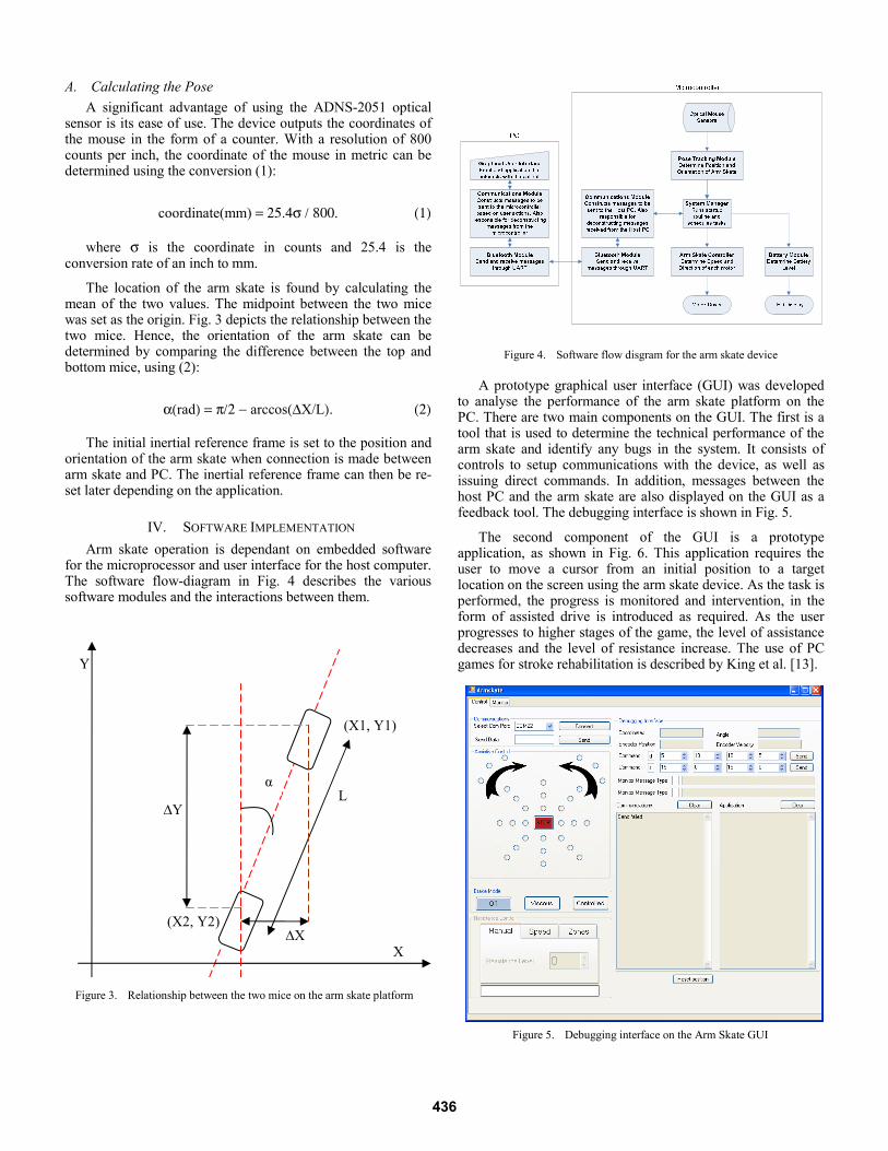
The location of the arm skate is found by calculating the mean of the two values. The midpoint between the two mice was set as the origin. Fig. 3 depicts the relationship between the two mice. Hence, the orientation of the arm skate can be determined by comparing the difference between the top and bottom mice, using (2):
α(rad) = π/2 − arccos(ΔX/L). (2)
The initial inertial reference frame is set to the position and orientation of the arm skate when connection is made between arm skate and PC. The inertial reference frame can then be re-set later depending on the application.
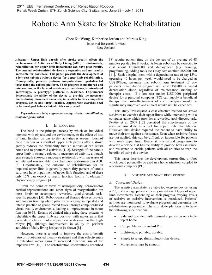
IV. SOFTWARE IMPLEMENTATION Arm skate operation is dependant on embedded software
for the microprocessor and user interface for the host computer. The software flow-diagram in Fig. 4 describes the various software modules and the interactions between them.
A prototype graphical user interface (GUI) was developed
to analyse the performance of the arm skate platform on the PC. There are two main components on the GUI. The first is a tool that is used to determine the technical performance of the arm skate and identify any bugs in the system. It consists of controls to setup communications with the device, as well as issuing direct commands. In addition, messages between the host PC and the arm skate are also displayed on the GUI as a feedback tool. The debugging interface is shown in Fig. 5.
The second component of the GUI is a prototype application, as shown in Fig. 6. This application requires the user to move a cursor from an initial position to a target location on the screen using the arm skate device. As the task is performed, the progress is monitored and intervention, in the form of assisted drive is introduced as required. As the user progresses to higher stages of the game, the level of assistance decreases and the level of resistance increase. The use of PC games for stroke rehabilitation is described by King et al. [13].
Figure 5. Debugging interface on the Arm Skate GUI
Figure 4. Software flow disgram for the arm skate device
X
L ∆Y
α
(X1, Y1)
∆X (X2, Y2)
Figure 3. Relationship between the two mice on the arm skate platform
Y
436

On the microprocessor end, the embedded software
deciphers instructions received from the host computer; perform any necessary calculations, and activates connected actuators or components as required. In addition, the embedded software is also responsible for collecting data from the various sensors that are connected to the input ports of the microcontroller. The information can then be analysed onboard and reported back to the GUI for display purposes; or sent to the host computer for more intensive processing. Whilst not currently implemented, these data can then be used to intelligently manage the behaviour of the arm skate for a more effective rehabilitation process.
V. RESULTS
A. Force testing Force testing was performed to determine if the arm skate is
able to deliver useful force to effectively assist or resist the movements of the arm skate user. To establish the maximum output force, maximum speed was applied. A load was placed on top of the arm skate and three readings were acquired using a dynamometer:
• South (reverse movement along the y-axis);
• East (movement to the right along the x-axis);
• North West (diagonal movement).
Other directions were not tested as the forces generated in those directions are symmetrical to the ones tested. Due to the configuration of the four motors, diagonal movements were expected to generate the least amount of force as only two motors are contributing to the force vector.
This was confirmed from the testing results. Furthermore, the tests revealed that the motors could produce so much force at peak output that the omniwheels slipped as there was not enough grip between the wheels and the surface of the table. The device delivered a minimum of 15N with a 2.5kg load.
Additional weight was then added to the arm skate. As a result, the minimum recorded force increased to 20N. Whilst the tests did not produce definitive figure of maximum output force, it did demonstrate the ability for the device to produce
sufficient force, and potentially more if the friction between wheels and table surface can be increased. The results are summarised in Tab. 1.
B. Localisation testing The localisation tests measured the ability to track the
location and orientation of the arm skate device. Three tests were performed to determine the accuracy and repeatability of the localisation approach. Physical markers on the bench-top were used as reference measures for the evaluation process.
1) Translational movement along the x-axis From a starting position, the arm skate was translated along
the x-axis (sideways) by a distance of 1500mm, and then moved back to the starting location. The x-coordinates were recorded at each 500mm interval, both on the outgoing and return journeys and compared to the physical measurements.
Four tests were performed and their average results are shown in Tab. 2. The experiments reveal a remarkably low error rate. After covering a distance of 3000mm, the localisation produced the maximum average error of 11.5mm which equates to an error rate of approximately 0.38%.
2) Translational movement along the y-axis Similar tests were performed along the y-axis, and the
average of the readings shown in Tab. 3. The maximum average error is 12.5mm at 1000mm, which equates to 1.2%. Whilst this is higher than the x-axis, it is still very low. Experiments were also performed by moving the arm skate along both x- and y-axes at the same time. The error rate was approximately the same as the previous results.
TABLE I. FORCES GENERATED BY THE ARM SKATE PLATFORM
Direction Force measured from arm skate (Newtons)
2.5kg Load 8kg Load
North West 15 20
South 22 33
East 23 32
Figure 6. Prototype of an activity based application that requires the movement of the arm skate to perform the required tasks
437

TABLE II. RESULTS OF DISPLACEMENT TEST TO DETERMINE THE ACCURACY OF THE MOUSE SYSTEM TO TRACK ITS POSITION ALONG THE X-AXIS
Marker location along the x-axis
(mm)
Average measured x-values (mm)
Average Error (mm)
Outgoing Return Outgoing Return
0 0 11.5 0 11.5 500 500.5 508 0.5 8 1000 999.25 1004.25 0.75 4.25 1500 1502.5 1502.5 2.5 2.5
TABLE III. RESULTS OF DISPLACEMENT TEST TO DETERMINE THE ACCURACY OF THE MOUSE SYSTEM TO TRACK ITS POSITION ALONG THE Y-AXIS
Marker location along the y-axis
(mm)
Average of measured Y-values (mm)
Average Error (mm)
Outgoing Return Outgoing Return
0 0 -10 0 10 500 495 493.75 5 6.25 1000 987.5 996 12.5 4 1500 1499.19 1499.19 0.81 0.81
3) Orientation Testing
Orientation tracking was tested by comparing recorded orientation readings with physical reference markers. Starting at 0° (platform pointing North), readings were collect at every 10° interval until the platform was at a -90° alignment. Similarly, the arm skate was then rotated clockwise until it reached an orientation of 90° (again stopping at every 10° interval), before finally rotating it counter-clockwise back to the starting orientation. Care was taken to ensure that no translational movement were introduced during rotation.
The results reveal that optical mouse has an operating range between -40° and 40°. Within this range, the arm skate is able to determine its orientation to an accuracy of +/-5°. However, when operating out of this range, device is highly erroneous or simply would not work at all. Full results are shown in Tab. 4. This limitation is due to the assumption that optical mice are used with minimal rotation i.e. in a straight line during normal operation. Under this operating condition, it is able to perform accurate coordinate measurements. However, if the mouse moves along a curve, the tracking algorithm deteriorates significantly.
TABLE IV. AVERAGE READINGS OF ARM SKATE ORIENTATION WHEN ROTATED FROM 0° TO -90° THEN TO 90°, BEFORE ROTATING BACK TO 0°
Physical angle
(degree)
Average Angle
Average Error
Physical angle
(degree)
Average Angle
Average Error
0 0.86 0.86 0 1.86 1.86 -10 -8.88 1.13 10 11.25 1.25 -20 -19.25 0.75 20 22 2 -30 -30.13 0.13 30 32.63 2.63 -40 -41.25 1.25 40 45.13 5.13 -50 -55.13 5.13 50 60.25 10.25 -60 -74.8 14.8 60 75.67 15.67 -70 0 70 70 0 70 -80 0 80 80 0 80 -90 0 90 90 0 90
Whilst this is a limitation, it may not be a big problem as the user would not need to rotate the arm skate past a certain angle. Trials will be required to determine how the arm skate is used to see if this limitation is significant. However, it is important to mention that the mouse does not completely fail when it has been rotated out of the operating range. Whilst it is beyond +/-40°, it reports nonsensical readings but as soon as rotates back into range, the data becomes accurate again, without needing to reset the system.
The final test was to determine the accuracy of orientation tracking after prolonged usage by moving the platform through sequences of random movements that included both translation and rotation. At the end of each sequence, the arm skate was orientated back to a marked reference point and an alignment of 0°; and the orientation reading was recorded. The results show that the overall tracking was quite accurate (Tab. 5). Nonetheless, it is recommended to reset the coordinate system occasionally to ensure errors do not accumulated over time.
VI. DISCUSSION This paper describes the development of a low cost robotic
device to assist rehabilitation exercises for the upper limb.
The concept is inherently safe due to the nature of the design concept. The robot is not able to overload the patient due to the relatively low force able to be transmitted through the omniwheel friction onto the work surface. However, the speed of response is still rapid.
In contrast, conventional robotic devices have a close relationship between the speed of response and the power of the actuators. Should a spastic reaction occur in the muscles of a stroke survivor during exercise a conventional robot may not be able to release the force fast enough for injury to be avoided. However, the friction connection between the work surface and the omniwheels means that the device described here has the ability to come free of the surface and so will not overload a person’s limbs.
Action observation in association with physical training can enhance the effects of motor training after stroke [19]. However, if the person cannot complete a reaching task at all then the action observation effect cannot take place.
TABLE V. ORIENTATION TRACKING AFTER SEQUENCES OF TRANSLATIONAL AND ROTATIONAL MOVEMENTS
Orientation of Arm Skate after random movements (degrees)
Test 1 Test 2 Test 3 Start 0 0 0 1st sequence 2 0 0 2nd sequence 2 1 2 3rd sequence 4 2 0 4th sequence 6 3 0 5th sequence 7 4 -1 6th sequence 5 4 -1 7th sequence 7 3 -1 8th sequence 8 3 -1 9th sequence 8 0 0 10th sequence 5 -2 -1
438

This device allows a person to undertake gravity supported exercises and successfully complete reaching tasks. The device is effectively an assistive device to allow a person to complete computer motivated reaching tasks during a gravity-supported training regime.
Although the forces able to be generated by the device are limited in comparison to other robotic systems, e.g. the MIT Manus delivers 45N [20], the arm skate device has advantages over such systems. It is smaller and therefore more portable, able to be set up in a patient’s home and be part of a homecare rehabilitation programme. The inherent safety aspects mean that supervision may not need to be as intense. If the device is easier to setup and cheaper to implement than standard 2 degree of freedom robots, then it will be more widely accepted in clinical practise than those more complex devices.
It is only essential that the device can deliver 28 N, which corresponds to the arm strength during elbow extension for a weak woman in seated position [21]. Experiments reveal that the arm skate device is more than capable in meeting this requirement. In fact, more power can be generated if the wheels have better a grip to the surface of the table. Adding weight to the arm skate device may be a solution, the other is to use a mat to introduce more friction.
The next step is to develop PC based exercise tasks to accurately test the full capabilities and usability of the arm skate system in the practical environment. Furthermore, trials are valuable to determine the optimum amount of assistive or resistive force (in strength and duration) to be applied at the correct timing so that the intervention is not perceived as a nuisance. An intelligent control system will be ideal for this situation. In addition, the patient’s progress must be monitored over a period of time, so that the effectiveness of the rehabilitation program for each individual can be assessed.
VII. CONCLUSIONS The concept of a tabletop robotic-assisted device for upper
limb rehabilitation has been successfully developed. Various experiments were performed and verified the platform’s capability of carrying the load of an arm and providing assistance and resistance to movement.
A novel localisation method was proposed and was shown to be very effective within the operating orientation of +/-40 degrees. Within this range, localisation was very accurate for both position and orientation tracking. Nonetheless, it is important to reset the coordinate system occasionally to ensure positional and orientation errors do not accumulate over time. In addition, the tests also revealed that the arm skate has a limited speed of operation. Further tests will be required to determine if these restrictions are significant with respect to the intended application.
ACKNOWLEDGMENT We thank the Foundation for Research Science and
Technology, NZ for funding this project, contract number CO8X0816.
REFERENCES [1] H. Nakayama, H. S. Jørgensen, H. O. Raaschou and T. S. H. Olsen,
“Compensation in recovery of upper extremity function after stroke: the Copenhagen Stroke Study,” Archives of Physical Medicine and Rehabilitation, vol. 75, pp. 852–857, 1994.
[2] S. M. Hunter and P. Crome, “Hand function and stroke,” Reviews in Clinical Gerontology, vol. 12, pp. 68–81, 2002.
[3] A. Sunderland, D. J. Tinson, E. L. Bradley, D. Fletcher, R. Langton Hewer and D. T. Wade, “Enhanced physical therapy improves recovery of arm function after stroke. A randomised clinical trial,” Journal of Neurology, Neurosurgery and Psychiatry, vol. 55, pp. 530–535, 1992.
[4] J. E. Harris and J. J. Eng, “Paretic upper-limb strength best explains arm activity in people with stroke,” Physical Therapy, vol. 87, pp. 88–97, 2007.
[5] B. H. Dobkin, The clinical science of neurologic rehabilitation, 2nd ed., Ocford: Oxford University Press, 2003.
[6] H. I. Krebs, B. T. Volpe and N. Hogan, “Robot-aided neurorehabilitation: from evidence-based to science-based rehabilitation,” Topics in Stroke Rehabilitation, vol. 8, pp. 54–70, 2002.
[7] S. E. Fasoli, H. I. Krebs, J. Stein, W. R. Frontera and N. Hogan, “Effects of robotic therapy on motor impairment and recovery in chronic stroke,” Arch. of Physical Medicine & Rehabilitation, vol. 84, pp. 477–82, 2003.
[8] G. Kwakkel, B. J. Kollen and H. I. Krebs, “Effects of robot-assisted therapy on upper limb recovery after stroke: A systematic review,” Neurorehabilitation and Neural Repair, vol. 22, pp. 1–11, 2007.
[9] A. R. Fugl-Meyer, L. Jaasko, I. Leyman, S. Olsson and S. Steglind, “The poststroke hemiplegic patient. 1. a method for evaluation of physical performance,” Scandinavian Journal of Rehabilitation Medicine, vol. 7, pp. 13-31, 1975.
[10] M. J. Johnson, X. Feng, L. M. Johnson and J. M. Winters, “Potential of a suite of robot/computer-assisted motivating systems for personalized, home-based, stroke rehabilitation,” Journal of NeuroEngineering and Rehabilitation, vol. 4, 2007.
[11] R. Hooper, (Retrived 2009, March 10). Learn about robots:Industrial robots [online]. Available: http://www.learnaboutrobots.com/ industrial.htm
[12] A. Peattie, A. Korevaar, J. Wilson, B. Sandilands, X. Q. Chen and M. King (2009), “Automated variable resistance system for upper limb rehabilitation,” in Australasian Conference on Robotics and Automation (ACRA), Sydney, Australia, 2009.
[13] C. K. Wong, J. Schmidt and W. K. Yeap, “Using a mobile robot for cognitive mapping,” in International Joint Conference on Artificial Intelligence (IJCAI), Hyderabad, India, 2007, pp. 2243–2248.
[14] M. E. Jefferies and W. K. Yeap (eds.), Robot and cognitive approaches to spatial mapping, Springer Tracts in Adv. Robotics, Springer, 2008.
[15] J. Borenstein, H. R. Everett, and L. Feng, Navigating mobile robots: Sensors and techniques, Wellesley, MA: A. K. Peters Ltd., 1996.
[16] M. Marijnissen (Retrieved 2010. June 14). Building a robot: Navigation [online]. Available: http://markmarijnissen.ruhosting.nl/robot/ index.php?p=navigation.
[17] V. Mattoli (Retrieved 2010, June 15). Optical displacement sensor [online]. Available: http://bdml.stanford.edu/twiki/bin/view/Rise/ OpticalDisplacementSensor.
[18] M. King, L. Hale, A. Pekkari, M. Persson, M. Gregorsson and M. Nilsson, “An affordable, computerized, table-based exercise system for stroke survivors,” Disability and Rehabilitation Assistive Technology, vol. 5, pp. 288–293, 2010.
[19] P. Celnik, B. Webster, D. M. Glasser, and L. G. Cohen, “Effects of action observation on physical training after stroke,” Stroke. vol. 39. pp. 1814–1820, 2008.
[20] H. I. Krebs, M. Ferraro, S. P. Buerger, M. J. Newbery, A. Makiyama, M. Sandmann, D. Lynch, B. T. Volpe, and N. Hogan, “Rehabilitation robotics: pilot trial of a spatial extension for MIT-Manus,” Journal of NeuroEngineering and Rehabilitation, vol. 1, 2004.
[21] N. Diffrient, A. R. Tilley and D. Harman, Humanscale 7/8/9. Cambridge, MA: MIT Press; 1981.
439